model 106 current meter operating manual
TRANSCRIPT

Model 106 Current Meter Operating Manual
Document ID MANUAL-1390768583-1 | issue: 1.1
Date: July 2021
This confidential document was prepared by the staff of Valeport Limited, the Company, and is the property of the Company, which also owns the copyright therein. All rights conferred by the law of the copyright and by virtue of international copyright conventions are reserved to the Company. This document must not be copied, reprinted or reproduced in any material form, either wholly or in part, and the contents of this document, and any method or technique available there from, must not be disclosed to any other person whatsoever without the prior written consent of the Company.
© 2021 Valeport Ltd
Valeport Ltd St Peter's Quay Totnes TQ9 5EW United Kingdom
Phone: email: Web:
+44 1803 869292 [email protected] www.valeport.co.uk
As part of our policy of continuous development, we reserve the right to alter, without prior notice, all specifications, designs, prices and conditions of supply for all our equipment
Contents
© 2021 – Valeport Ltd Page | 2
Contents 1 Introduction................................................................................................................. 4
1.1 General Description .............................................................................................................. 4
1.2 Self-Recording Mode ............................................................................................................ 4
1.2.1 Direct Reading Mode ................................................................................................................... 4
1.2.2 Configuration and Data Download ............................................................................................... 4
2 System Description ..................................................................................................... 5
2.1 Instrument - Model 106 ......................................................................................................... 5
2.1.1 Dimensions .................................................................................................................................. 6
2.2 Surface units ......................................................................................................................... 7
3 Installation .................................................................................................................. 8
3.1 Mechanical Installation ......................................................................................................... 8
3.2 Electrical Connections .......................................................................................................... 9
3.2.1 Direct RS232 - PC operation only ................................................................................................ 9
3.2.2 Digital Current Loop ................................................................................................................... 10
3.3 Serial Data Format.............................................................................................................. 10
3.4 Batteries .............................................................................................................................. 10
3.4.1 8008 - CDU ................................................................................................................................ 10
4 Operation Using 8008 CDU ...................................................................................... 11
4.1 Operating Procedure .......................................................................................................... 11
4.2 Data Replay ........................................................................................................................ 14
4.3 External Connections ......................................................................................................... 14
4.4 Printer Output...................................................................................................................... 14
4.4.1 106 Printer String ....................................................................................................................... 15
4.5 Storage Capacity ................................................................................................................ 16
5 Maintenance ............................................................................................................. 17
5.1 Battery Replacement .......................................................................................................... 17
5.2 Battery Replacement - 8008 CDU ...................................................................................... 17
5.3 Impeller ............................................................................................................................... 18
5.3.1 Cleaning:.................................................................................................................................... 18
5.3.2 Impeller Shaft: ............................................................................................................................ 18
5.3.3 Refitting the Impeller .................................................................................................................. 18
5.4 General ............................................................................................................................... 18
5.5 O-Ring Sizes ....................................................................................................................... 19
5.6 Lithium Back UP Battery ..................................................................................................... 19
6 Calibration ................................................................................................................ 20
Contents
© 2021 – Valeport Ltd Page | 3
Appendix 1 Figures ........................................................................................................ 21
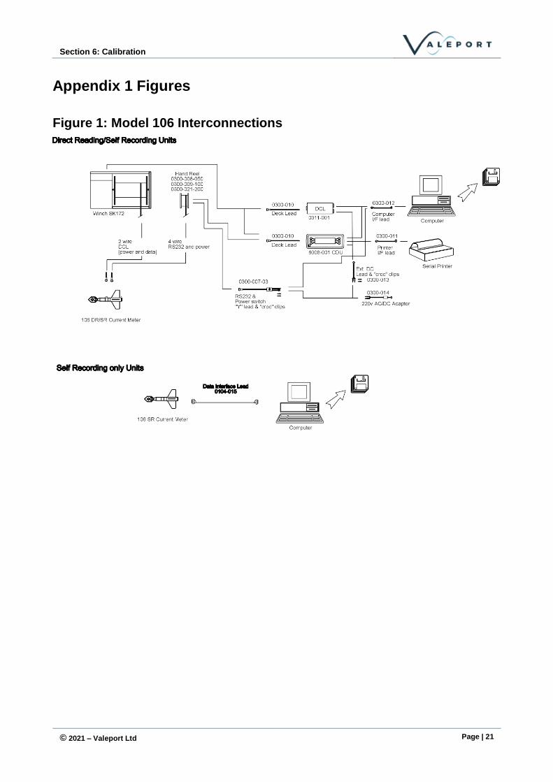
Figure 1: Model 106 Interconnections .......................................................................................... 21
Figure 2: Model 106 Sensor Layout ............................................................................................. 22
Appendix 2 Cable Wiring Schemes ................................................................................ 23
106 Fish SubConn Connector ...................................................................................................... 23
Y Lead ........................................................................................................................................... 23
8008 Comms & Power Lead (SubConn to Milspec) .................................................................... 24
Digital Current Loop / 8008 Surface Unit Connectors.................................................................. 25
DC Input ............................................................................................................................................... 25
RS232 .................................................................................................................................................. 25
Deck Lead ............................................................................................................................................ 25
Appendix 3 Operation with DataLog x2 .......................................................................... 26
Model 106 Self Recording/Direct Reading Current Meters Operating Manuel:
MANUAL-1390768583-1 | issue: 1.1
© 2021 – Valeport Ltd Page | 4
1 Introduction
This document covers the installation and operation of Model 106 Self-Recording/Direct Reading Current Meter, when used with the 8008 Control Display Unit.
It also covers general maintenance procedures, and the calibration data of the units. Operation of the Meters with Windows PC software is covered in the supplementary DataLog x2 software manual.
1.1 General Description
The Model 106 is an impeller-based meter measuring speed and direction, with optional temperature and depth parameters.
The 106 can be operated in a self-recording mode or in direct reading mode via a PC. Alternatively the Model 8008 Control Display Unit can be used for controlling Direct Reading operation:
1.2 Self-Recording Mode
Instrument setup and data extraction can be carried out using the supplied Y lead from PC to external 10 way SubConn connector.
1.2.1 Direct Reading Mode
Over short cable lengths (up to 100m) RS232 communications are possible via the external 10
Way SubConn connector and PC.
Over longer cable lengths, communications are via Digital Current Loop. The 8008 CDU has an integral current loop adapter, so direct use of the instruments with this unit is possible. If it is required to use the meters with a PC over long cable lengths, a separate Digital Current Loop Adapter will be required.
Power to the Model 106 may be taken from their internal battery, from the 8008 CDU (if used) or from a surface battery or power supply.
When power is taken from the internal battery (1.5V alkaline D cell), battery life is approximately 30 days at 10 second sampling rate, or 56 days at 5-minute sample rate.
Using a 3.6V Lithium D cell, life is approximately 90 days at 10-second sample rate, or 180 days at 5-minute sample rate.
The 106 is fitted with a 512K memory. This equates to storage of over 131000 speed and direction records (over 65000 if temperature and depth are also fitted) provided the data is stored in a single file.
The CDU is fitted with a 128K memory. This equates to storage of over 32000 speed and direction records (over 10000 if temperature and depth are also fitted).
Both 106 and CDU have a limit of 100 files.
1.2.2 Configuration and Data Download
The 106 is supplied with DataLog x2 software for setup and data offload and display with a number
of alphanumeric and graphical options.
Please see separate manual – 04008373 – DataLog x2 and Terminal x2 Operating Manual
Section 2: System Description
© 2021 – Valeport Ltd Page | 5
2 System Description
2.1 Instrument - Model 106
The instrument contains all of the measurement sensors and electronics. The current meter works on a basic 1-second cycle, during which the impeller counts are taken and a single compass heading reading is made. From this, East and North velocity vectors are calculated, which are then summed over the averaging period. The additional parameters of temperature and pressure (if
fitted) are sampled once every sample period, and averaged over the averaging period.
Note that at very low flow speeds (of the order of a few centimetres per second), it will be necessary to set a reasonably long averaging period to improve the resolution and accuracy of the flow measurements.
The Model 106 is fitted with a data acquisition micro-controller, operating at 12-bit resolution. The temperature and depth sensors operate on a basic 16 Hz sampling rate and the samples are sequential.
When in Self-Recording mode, the instrument logs raw data. In real time mode, the calibration constants in the instrument software are used to calculate the actual temperature and pressure readings within the instrument, and the 8008 Surface Unit or PC reads this data. When logged data is extracted, the raw data is transferred to the PC and then the Windows software automatically converts the data to engineering units. This operation is covered in the supplementary software manual.
Optional sensors that can be fitted are a thermistor temperature sensor and strain gauge pressure transducer. The type and range of transducer actually fitted is defined in the calibration sheet.
Model 106 Self Recording/Direct Reading Current Meters Operating Manuel:
MANUAL-1390768583-1 | issue: 1.1
© 2021 – Valeport Ltd Page | 6
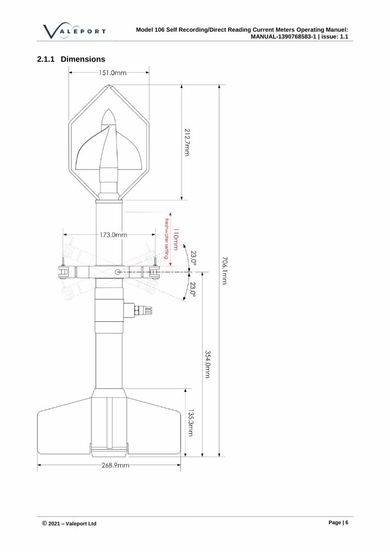
2.1.1 Dimensions

Section 2: System Description
© 2021 – Valeport Ltd Page | 7
2.2 Surface units
If operating the Model 106 via PC, it is possible to achieve direct RS232 communications over short cable lengths (up to about 50m). If longer cable lengths are being used, it will be necessary to use a Digital Current Loop Adapter (DCL). The DCL adapter enables data on power communications over a single pair of conductors.
If operation is with a Model 8008 Surface Unit, a DCL adapter will not be necessary, since the 8008 has this communication method built in, with selection defined by the cable connections.

Model 106 Self Recording/Direct Reading Current Meters Operating Manuel:
MANUAL-1390768583-1 | issue: 1.1
© 2021 – Valeport Ltd Page | 8
3 Installation
3.1 Mechanical Installation
Impeller
Impeller
Guard
SubConn
ConnectorSuspension
Assembly
Lock
Ring
Tail Fin
Assembly
The instrument is provided with a suspension assembly for users to attach to a suspension or mooring line. If the Valeport polyurethane covered multi-core cable is being used, then this has a maximum working load of 100kgf, and if a sinker weight is being used, it is important that this load is not exceeded.
For correct operation of the impeller, two procedures must be performed prior to deployment:
The inner part of the impeller should be filled with clean water
This is achieved by unscrewing the impeller nose cap, and submerging the impeller to allow water to fill the inside. While it is still underwater, refit the nose cap to seal the water inside.
The meter must be balanced so that it is suspended horizontally in the water
Due to the fact that the meter is made from materials of different densities, the balance of the meter will be slightly affected by different salinities. For this reason, the suspension assembly can be moved along the main body to compensate.
• First, tilt the assembly to expose the lock ring around the main body.
• Slightly loosen the 2.5mm socket countersunk 316 titanium screw, until the lock ring can be slipped along the surface of the body.
• Immerse the meter, and adjust the position of the suspension assembly until the unit sits horizontally in the water.
• Finally, tighten the 2.5mm screw to fix the lock ring in place. Do not over tighten.
Failure to observe these points will result in decreases in operating efficiency, accuracy and impeller life
Section 3: Installation
© 2021 – Valeport Ltd Page | 9
3.2 Electrical Connections
See also Appendix 2 for cable wiring details.
The SubConn connector version of the Model 106 no longer incorporates a seawater switch mechanism. For self-recording deployments a 10 way SubConn switch cap must be fitted or the unit will not operate
3.2.1 Direct RS232 - PC operation only
Over short lengths of cable in Direct Reading mode and for setting up recording scenario and replay of data via the 3m data/power lead in Self-Recording mode, the instrument RS232 communications can be used.
3.2.1.1 Direct Reading Mode
In Direct Reading mode, connect the instrument to the PC via the signal cable and 3m-power/data lead. The data lead should be plugged into a serial port on the PC (if the PC has no 9 pin serial port, use supplied RS232/USB adaptor). The software sets up the serial port of the PC to 4800 baud, 8 data, 1 stop, no parity.
Although the D cell battery in the fish is capable of driving the RS232 communications, battery life will be significantly reduced, and it is recommended that external power is used.
If external power is being used it must be in the range of 12 to 28V DC and the consumption is approximately 40mA depending on the parameters. The red lead should be connected to the +ve terminal and the black lead should be connected to the -ve terminal of the power supply or external
battery.
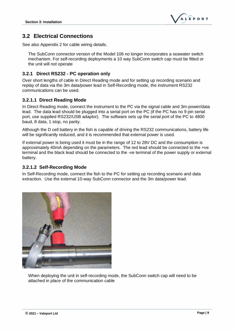
3.2.1.2 Self-Recording Mode
In Self-Recording mode, connect the fish to the PC for setting up recording scenario and data extraction. Use the external 10-way SubConn connector and the 3m data/power lead.
When deploying the unit in self-recording mode, the SubConn switch cap will need to be attached in place of the communication cable
Model 106 Self Recording/Direct Reading Current Meters Operating Manuel:
MANUAL-1390768583-1 | issue: 1.1
© 2021 – Valeport Ltd Page | 10
3.2.2 Digital Current Loop
In Direct Reading Mode, where cable lengths are in excess of 50m, it will be necessary to communicate via Digital Current Loop. This is done automatically by the Model 8008 Surface Unit, but if operation is via PC a Digital Current Loop adapter will be required. The unit requires 12-24V DC external power, and takes approximately 120 mA. Connection is via the Deck Lead to the main signal cable, and via data interface lead) to the RS232 communications port on the PC. A variety of power cables are offered as options.
3.3 Serial Data Format
The serial data format as transmitted from the 106 depends on the parameters fitted.
The serial data string below shows the data string for a 106 with all parameters fitted. If temperature and pressure are not fitted, only speed and direction are available. The data string is fixed width and padded with zeros as required - there is no delimiter.
S = s.sssD = ddd.ddP = sppp.pppT = tt.ttt<CR><LF>
Where:
S denotes Speed
D denotes Direction
P denotes Pressure
T denotes Temperature
s.sss = Speed reading
ddd.dd = Flow heading
sppp.ppp = Pressure reading where s is the sign
tt.ttt = Temperature reading
3.4 Batteries
The internal battery contains one D cell (either alkaline or Lithium), which has a capacity of 10.5 Ah if a high-grade cell is used. The overall current consumption of the unit depends on the sampling set up. Typical battery life figures are shown below.
When power is taken from the internal battery (1.5V alkaline D cell), battery life is approximately 30 days at 10 second sampling rate, or 56 days at 5-minute sample rate.
Using a 3.6V Lithium D cell, life is approximately 90 days at 10-second sample rate, or 180 days at 5-minute sample rate.
To aid the user in determining how much battery life remains, the battery voltage is displayed in DataLog x2.
3.4.1 8008 - CDU
The 8008 contains 8 "C" cells, giving an operating lifetime for the batteries in excess of 40 hours continuous use. The CDU will operate on a 12vDC external DC supply. See Section 5.2 for details of how to change the batteries.

Section 4: Operation Using 8008 CDU
© 2021 – Valeport Ltd Page | 11
4 Operation Using 8008 CDU
The 8008 CDU is of ABS construction with graphics LCD and backlight, membrane keys and integral battery compartment. The unit is sealed to IP67 (10 seconds at 0.3 metres).
The 8008 CDU is designed to allow real time display of data from an underwater unit, and to enable the setting of parameters for a Model 106. It is possible to connect the 8008 to a printer for a permanent record of the data, and it has an optional logging facility of its own. However, this does not allow uploading of logged data from the memory of the fish; a PC is required for this function.
CDU express is software supplied on a CD with the 8008 unit to allow for easy extraction of logged data from the 8008 to a PC. Please refer to the CDU express manual for details on operation
4.1 Operating Procedure
Connect the CDU to the Current Meter using the Deck Lead and cable for Direct Reading or Both
modes, or the 3m 'Y' Lead for Self-Recording mode. Then follow the procedure laid out below:
Function Description
Press ON Unit switches on with introductory display
Press any key to continue
Unit displays RUN, SETUP, TOGGLE B'LIGHT, SET TIME/DATE, CDU MEMORY
Set TIME/DATE Probably the most important as all timing references are made from this including the setting of fish time. Use INCREASE/DECREASE keys to alter figures and NEXT key to move on to next figure. EXIT will set and escape to previous menu.
TOGGLE BACK LIGHT Switches back light on or off.
CDU MEMORY Controls the logging facility on the 8008 CDU. Pressing this key reveals the CDU LOGGING MENU. Full details of this menu are covered later, but the most important function in this menu is turning the logging facility ON and OFF. This function is completely independent of the fish; i.e. it is possible to have the CDU logging but not the fish, or vice versa, or both or neither.
SET UP Allows set up of sample and averaging periods. Press SETUP key. PLEASE WAIT RESETTING FISH!! is displayed followed by INTERRUPTING FISH - PLEASE WAIT. Display will now show instrument type and serial number and prompts you to acknowledge by pressing O.K. key.
The following functions are revealed:
SET SAMPLE PERIOD Sample frequency is set using the CHANGE key to alter figures and TOGGLE key to move to next figure. The sample period can be incremented in periods of 1 second, to a maximum of 59:59 minutes. EXIT to set and return to previous menu.
Model 106 Self Recording/Direct Reading Current Meters Operating Manuel:
MANUAL-1390768583-1 | issue: 1.1
© 2021 – Valeport Ltd Page | 12
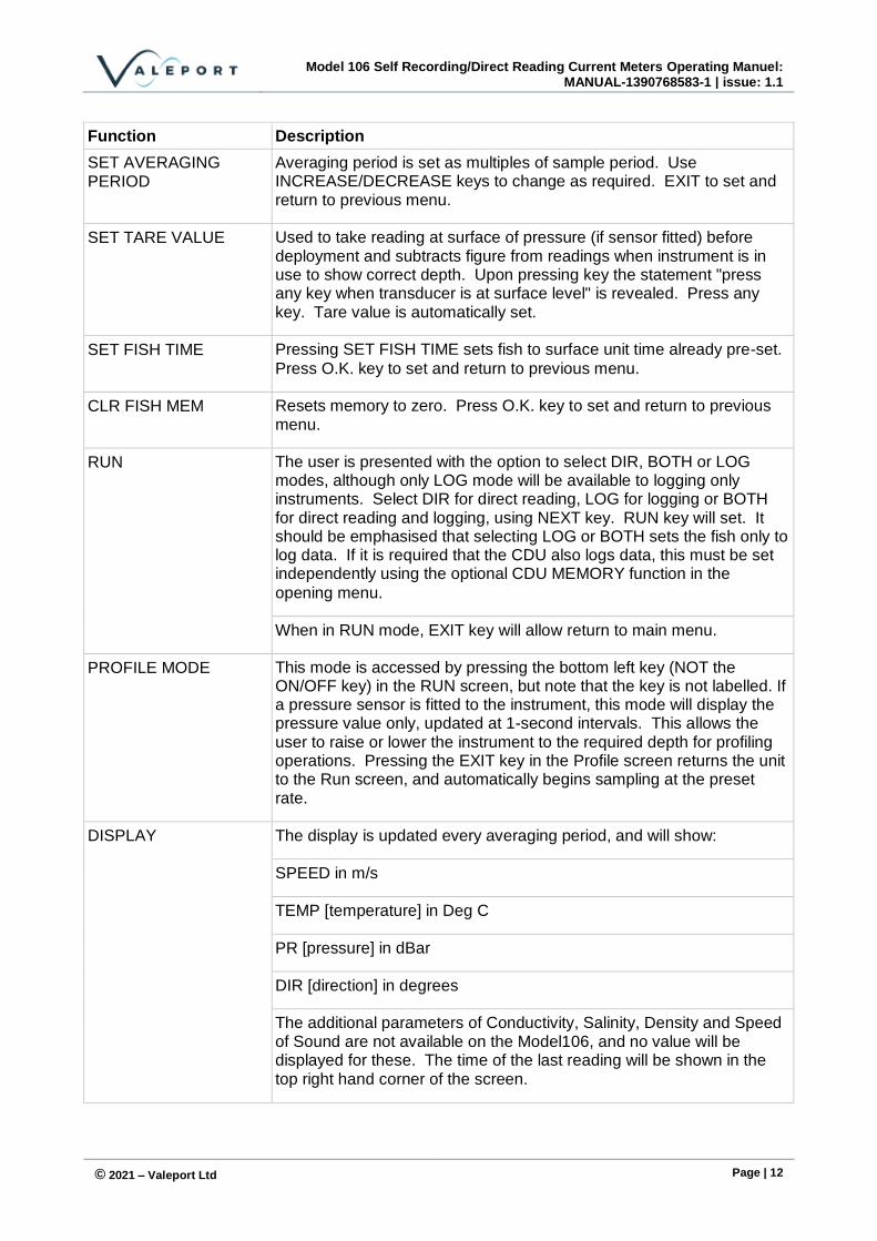
Function Description
SET AVERAGING PERIOD
Averaging period is set as multiples of sample period. Use INCREASE/DECREASE keys to change as required. EXIT to set and return to previous menu.
SET TARE VALUE Used to take reading at surface of pressure (if sensor fitted) before deployment and subtracts figure from readings when instrument is in use to show correct depth. Upon pressing key the statement "press any key when transducer is at surface level" is revealed. Press any key. Tare value is automatically set.
SET FISH TIME Pressing SET FISH TIME sets fish to surface unit time already pre-set.
Press O.K. key to set and return to previous menu.
CLR FISH MEM Resets memory to zero. Press O.K. key to set and return to previous menu.
RUN The user is presented with the option to select DIR, BOTH or LOG modes, although only LOG mode will be available to logging only instruments. Select DIR for direct reading, LOG for logging or BOTH for direct reading and logging, using NEXT key. RUN key will set. It should be emphasised that selecting LOG or BOTH sets the fish only to log data. If it is required that the CDU also logs data, this must be set independently using the optional CDU MEMORY function in the
opening menu.
When in RUN mode, EXIT key will allow return to main menu.
PROFILE MODE This mode is accessed by pressing the bottom left key (NOT the ON/OFF key) in the RUN screen, but note that the key is not labelled. If a pressure sensor is fitted to the instrument, this mode will display the pressure value only, updated at 1-second intervals. This allows the user to raise or lower the instrument to the required depth for profiling operations. Pressing the EXIT key in the Profile screen returns the unit to the Run screen, and automatically begins sampling at the preset rate.
DISPLAY The display is updated every averaging period, and will show:
SPEED in m/s
TEMP [temperature] in Deg C
PR [pressure] in dBar
DIR [direction] in degrees
The additional parameters of Conductivity, Salinity, Density and Speed of Sound are not available on the Model106, and no value will be displayed for these. The time of the last reading will be shown in the top right hand corner of the screen.

Section 4: Operation Using 8008 CDU
© 2021 – Valeport Ltd Page | 13
Function Description
If the CDU logging facility is set, the record and file number will be displayed at the top left hand corner of the screen.
If the fish is set to Log only mode, no data will be displayed on the screen during Run.
CDU MEMORY Pressing this key in the opening menu reveals the CDU LOGGING MENU, which contains: FILE TABLE, LOGGING ON/OFF, MEMORY FREE, EXTRACT CDU DATA, ERASE MEMORY, EXIT.
FILE TABLE This key reveals a display showing the total number of files stored (maximum 100), the size of each file, the sample and averaging period of the data, and the time/date of the first record in each file. A new file is created each time the unit is set to Run. To move between files, use the NEXT and LAST keys. Press EXIT to return to the previous menu.
LOGGING ON/OFF As stated previously, this key toggles between logging on and off, for the CDU only.
MEMORY FREE Displays the total unused memory space in bytes, and the number of files currently stored. Press EXIT to return to previous menu.
ERASE MEMORY Clears CDU memory. This will not affect the fish memory.
EXTRACT CDU DATA Use this key to upload data stored in the CDU to a PC. Connect the 8008 CDU to a PC using the interface lead provided and run CDU Express on the PC. For details on how to operate CDU express, please refer to the CDU express manual.
Model 106 Self Recording/Direct Reading Current Meters Operating Manuel:
MANUAL-1390768583-1 | issue: 1.1
© 2021 – Valeport Ltd Page | 14
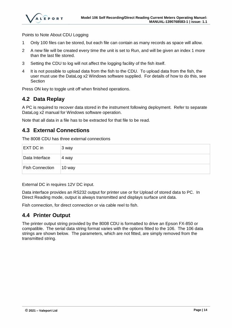
Points to Note About CDU Logging
1 Only 100 files can be stored, but each file can contain as many records as space will allow.
2 A new file will be created every time the unit is set to Run, and will be given an index 1 more than the last file stored.
3 Setting the CDU to log will not affect the logging facility of the fish itself.
4 It is not possible to upload data from the fish to the CDU. To upload data from the fish, the user must use the DataLog x2 Windows software supplied. For details of how to do this, see Section
Press ON key to toggle unit off when finished operations.
4.2 Data Replay
A PC is required to recover data stored in the instrument following deployment. Refer to separate
DataLog x2 manual for Windows software operation.
Note that all data in a file has to be extracted for that file to be read.
4.3 External Connections
The 8008 CDU has three external connections
EXT DC in 3 way
Data Interface 4 way
Fish Connection 10 way
External DC in requires 12V DC input.
Data interface provides an RS232 output for printer use or for Upload of stored data to PC. In Direct Reading mode, output is always transmitted and displays surface unit data.
Fish connection, for direct connection or via cable reel to fish.
4.4 Printer Output
The printer output string provided by the 8008 CDU is formatted to drive an Epson FX-850 or compatible. The serial data string format varies with the options fitted to the 106. The 106 data strings are shown below. The parameters, which are not fitted, are simply removed from the transmitted string.

Section 4: Operation Using 8008 CDU
© 2021 – Valeport Ltd Page | 15
4.4.1 106 Printer String
<ff>VALEPORT LTD.<cr><lf> DATE: DD/MM/YYYY <cr><lf> SAMPLE PERIOD=Xs <cr><lf> Rec no.<t>TIME<t><t>SPEED<t>DIR<t>PRESS<t>TEMP<t><cr><lf> <t><t><t>M/S<t>Deg<t>dbar<t>DegC<t><cr><lf> nnnnn<t>hh:mm:ss<t>f.fff<t>ddd.d<t>sppp.ppp<t>stt.ttt<t><cr><lf> nnnnn<t>hh:mm:ss<t>f.fff<t>ddd.d<t>sppp.ppp<t>stt.ttt<t><cr><lf> nnnnn<t>hh:mm:ss<t>f.fff<t>ddd.d<t>sppp.ppp<t>stt.ttt<t><cr><lf> : : etc for 57 Records
Where <ff> = Form feed <cr> = Carriage return <lf> = Line feed <t> = Tab DD = Day of month MM = Month of year YYYY = Year X = Sample period nnnn = Record number hh = Hour of day mm = Minute of hour ss = Second of minute f.fff = Flow reading ddd.d = Flow heading sppp.ppp = Pressure reading where s is the sign stt.ttt = Temperature reading where s is the sign
Model 106 Self Recording/Direct Reading Current Meters Operating Manuel:
MANUAL-1390768583-1 | issue: 1.1
© 2021 – Valeport Ltd Page | 16
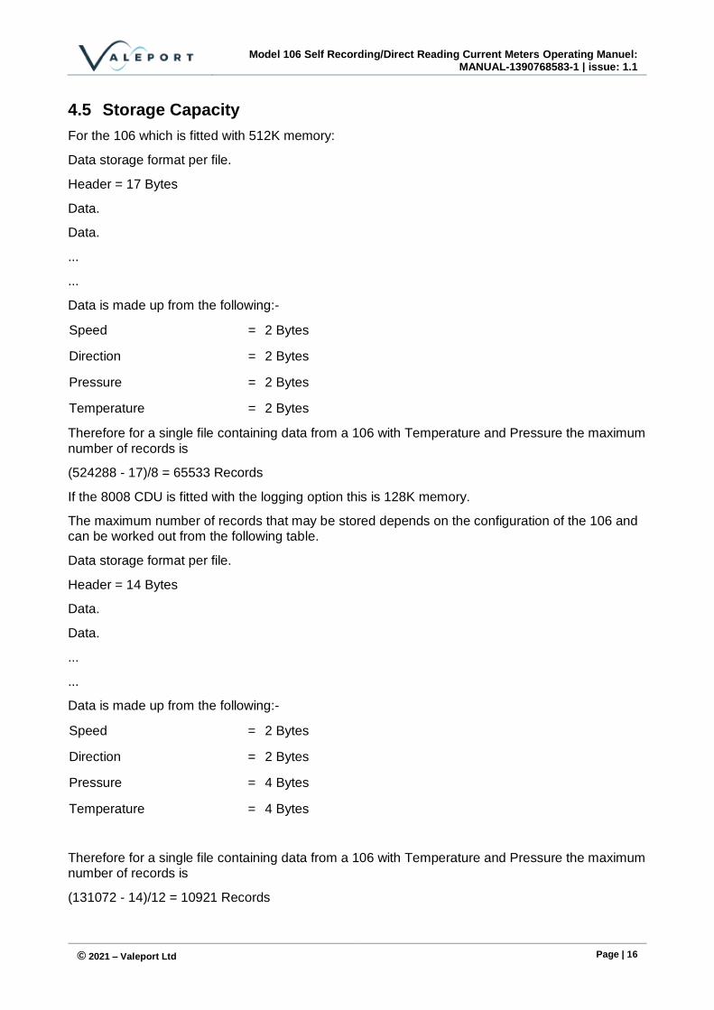
4.5 Storage Capacity
For the 106 which is fitted with 512K memory:
Data storage format per file.
Header = 17 Bytes
Data.
Data.
...
...
Data is made up from the following:-
Speed = 2 Bytes
Direction = 2 Bytes
Pressure = 2 Bytes
Temperature = 2 Bytes
Therefore for a single file containing data from a 106 with Temperature and Pressure the maximum
number of records is
(524288 - 17)/8 = 65533 Records
If the 8008 CDU is fitted with the logging option this is 128K memory.
The maximum number of records that may be stored depends on the configuration of the 106 and can be worked out from the following table.
Data storage format per file.
Header = 14 Bytes
Data.
Data.
...
...
Data is made up from the following:-
Speed = 2 Bytes
Direction = 2 Bytes
Pressure = 4 Bytes
Temperature = 4 Bytes
Therefore for a single file containing data from a 106 with Temperature and Pressure the maximum number of records is
(131072 - 14)/12 = 10921 Records
Section 5: Maintenance
© 2021 – Valeport Ltd Page | 17
5 Maintenance
5.1 Battery Replacement
The single D cell battery (alkaline or Lithium) is housed within the instrument at the front end. The procedure to replace the battery is as follows:
1. Remove the four M3 titanium countersunk screws on the impeller side of the central bulkhead.
2. Gently slide the outer housing and impeller assembly off the bulkhead, taking great care not to
scratch or damage the internal bore of the housing.
3. The battery cage accepts a single D cell. It is advisable to use an alkaline cell as this gives increased life and leakage protection. The batteries should be inserted with the contacts towards the front, making sure that the connector lead is firmly in place before clipping the battery into the holder.
4. Before replacing the housing, check the condition of the O-rings, which should be free of cuts or perishing. Also check the condition of the sealing bores of the housing which should be free of scratches. Finally smear a light coating of silicon grease on the O-rings and housing
sealing bores to aid refitting and subsequent removal.
5. Further reassembly is a reversal of the disassembly process.
Should any of the M3 countersunk screws be lost it is imperative that they are only replaced with titanium M3 x 6 countersunk screws, otherwise there is a risk that galvanic corrosion will occur
which could seriously damage the housing.
5.2 Battery Replacement - 8008 CDU
The batteries are housed within the CDU under the battery cover. The procedure for replacing these is as follows:
1. Remove the battery cover.
2. Remove the top PCB by undoing the retaining screw to reveal the battery cells.
3. The battery accepts 8 "C" cells [LR14 or equivalent]. It is advisable to use alkaline cells as this gives increased life and leakage protection. The batteries should be inserted -ve end against the spring and the top PCB should then be screwed back into place.
4. Before replacing the battery cover; check the condition of the O-rings, which should be free of cuts or perishing. Also check the condition of the sealing bores of the battery cover which should be free of scratches. Finally smear a light coating of silicon grease on the O-rings and
battery cover sealing bores to aid refitting and subsequent removal.
Model 106 Self Recording/Direct Reading Current Meters Operating Manuel:
MANUAL-1390768583-1 | issue: 1.1
© 2021 – Valeport Ltd Page | 18
5.3 Impeller
The impeller should be free to rotate. Positioning the instrument vertically and spinning the impeller can test this. Note that when the instrument is horizontal and not in water, the bearings are dry and the impeller is not neutrally buoyant, so the impeller may not rotate freely.
To Remove the Impeller:
1. Remove the impeller guard by unscrewing the guard away from the main body.
2. Remove the impeller nose cap [yellow]
3. Remove the two M3 nuts from the impeller shaft
4. Slide the impeller off the shaft
5.3.1 Cleaning:
Wash the inside of the impeller, and clean any residue from the impeller shaft.
5.3.2 Impeller Shaft:
If it is required to reset the impeller shaft, it is necessary to set its position to ensure correct operation:
1. Position the instrument with the shaft pointing upwards with the shaft in approximately the correct position
2. Without the guard fitted, replace the impeller on the shaft with the nose cone fitted
3. Unscrew the nose cone to allow the impeller to rest against the instrument body hub face
4. Lightly hold down the impeller down against the hub face, and slowly screw down the nose
cone until it tightens and thereby wants to lift the impeller away from the hub face
5. Check the clearance between nose cone and impeller end face and adjust the shaft so that the
clearance is 0.5 to 0.75mm. Ensure the shaft and lock nut are tightened and recheck the gap.
6. Refit the nose cone and impeller.
5.3.3 Refitting the Impeller
This is a reversal of removal.
5.4 General
The external parts of the meter are manufactured from titanium and polymers and are therefore corrosion resistant. The titanium will become dull in appearance with use. The sensor end should be kept clean from mud and debris to maintain accuracy of sensors. Washing off with clean water is therefore advised after use. After use the impeller should be washed, and it is recommended that the impeller assembly is removed and washed through to prevent the creation of salt deposits which will affect the subsequent performance of the impeller.
Should problems be encountered with the instrument, then Valeport Limited should be contacted immediately. Valeport will then be pleased to advise on the correct course of action.
Tel: +44(0)1803 869292
E-Mail: [email protected]
Section 5: Maintenance
© 2021 – Valeport Ltd Page | 19
5.5 O-Ring Sizes
Line connector 1 x 200-016-4470
Bulkhead connector pro-cap 1 x 200-016-4470
Bulkhead Connector/Housing 2 x 200-115-4470
End Cap, sensor end 1 x 200-128-4470 plus 1 x 128 anti-extrusion rings
Centre section/housings 2 x 200-129-4470 plus 2 x 129 anti-extrusion rings
Note that anti-extrusion backing rings are used on the sensor end O-rings and the O-rings should be placed on the pressure [seawater] side of the anti-extrusion ring.
The Dowty seal used in the temperature sensor is type 303.
5.6 Lithium Back UP Battery
The memory back-up lithium battery, (Type T047BA9, 3.6V), should be replaced at least every 5 years. If the memory and or clock settings are lost then the battery should be replaced. It is recommended that the instrument be returned to Valeport Limited for replacement of this battery, however if urgent renewal is required then the replacement procedure is as follows:
The battery is housed within the battery/internal connection part of the housing.
1. Remove the front battery housing section, as in Section 5.2 'Battery Replacement'.
2. The battery is connected to board 0104502 by wire, but is situated within the main bulkhead. It is therefore necessary to remove the board.
3. Do this by removing the screws in the two PCB support bars. This should allow the board to be gently removed, with the Lithium battery sliding out of the main bulkhead.
4. Remove the heat shrink tube around the battery, and de-solder the old cell. Fit and solder the wires to the new battery, and replace the heat shrink tube (19mm bore).
5. Reassembly is a reversal of the above procedure. Before replacing the rear tube, check the condition of the O-rings, which should be free of cuts or perishing. Also check the condition of the sealing bores of the main tube which should be free of scratches. Finally smear a light coating of silicon grease on the O-rings and rear tube sealing bores to aid refitting and
subsequent removal.
Model 106 Self Recording/Direct Reading Current Meters Operating Manuel:
MANUAL-1390768583-1 | issue: 1.1
© 2021 – Valeport Ltd Page | 20
6 Calibration
The instruments are calibrated at the factory using industry standard methods, and the calibration certificate is supplied with the instrument.
The impellers are group calibrated at HR Wallingford, allowing impellers to be changed at any time without the need for recalibration. Refer to Section 5.3 for details of how to do this.
The following is the seventh order polynomial used for the group calibration of the 106 impeller current meter:
where
a7=+7.07192656496855E-13
a6=-1.77441548834011E-10
a5=+1.23103627071919E-08
a4=-2.76434849230036E-09
a3=-2.417253365201895E-05
a2=+8.0250814202725E-04
a1=+2.80829724067969E-01
a0=+1.72164197365799E-02
If users require to recalibrate the instrument, then the calibration constants held within the instrument can be changed. Please refer to the factory regarding the method of carrying out this
procedure.
y a x a x a x a x a x a x a x a= + + + + + + +7
7
6
6
5
5
4
4
3
3
2
2
1
1
0
Section 6: Calibration
© 2021 – Valeport Ltd Page | 21
Appendix 1 Figures
Figure 1: Model 106 Interconnections
Model 106 Self Recording/Direct Reading Current Meters Operating Manuel:
MANUAL-1390768583-1 | issue: 1.1
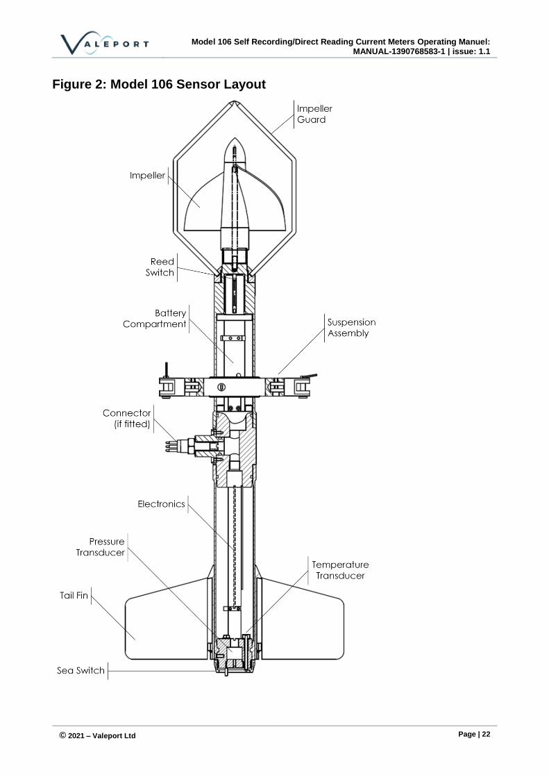
© 2021 – Valeport Ltd Page | 22
Figure 2: Model 106 Sensor Layout

Section 6: Calibration
© 2021 – Valeport Ltd Page | 23
Appendix 2 Cable Wiring Schemes
Wiring colours are correct at the time the manual was printed. However, it is advised that continuity checks are performed prior to all terminations.
106 Fish SubConn Connector
10 Way SubConn Connector Pin Function
MCBH10F +DLSA-F – Locking Sleeve
2 External Supply
8 RS232 into Fish
1 (Connect to Pin 9)
Ground
7 RS232 out of Fish
10 Sea Switch
Y Lead
End 1: SubConn MCIL10M
+DLSA-M4M
End 2:
End 3: 9 Way D Socket RS 465-362 with hood (RS 480-119)
Function Pin Pin
10 Black 4mm Plug RS 444-797 (Join in plug)
Internal Battery Enable
1 -V Supply
2 Red 4mm Plug
RS 444-832 +V Supply
3 RS422 TXA (N.C.)
4 RS422 TXB (N.C.)
5 RS422 RXA (N.C.)
6 RS422 RXB (N.C.)
7 2 RS232 TX (out of unit)
8 3 RS232 RX (in to unit)
9 1, 5, 6, 8, 9 - SHELL RS232 GND
Model 106 Self Recording/Direct Reading Current Meters Operating Manuel:
MANUAL-1390768583-1 | issue: 1.1
© 2021 – Valeport Ltd Page | 24
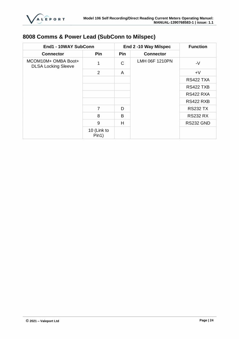
8008 Comms & Power Lead (SubConn to Milspec)
End1 - 10WAY SubConn End 2 -10 Way Milspec Function
Connector Pin Pin Connector
MCOM10M+ OMBA Boot+ DLSA Locking Sleeve
1 C LMH 06F 1210PN
-V
2 A +V
RS422 TXA
RS422 TXB
RS422 RXA
RS422 RXB
7 D RS232 TX
8 B RS232 RX
9 H RS232 GND
10 (Link to Pin1)
Section 6: Calibration
© 2021 – Valeport Ltd Page | 25
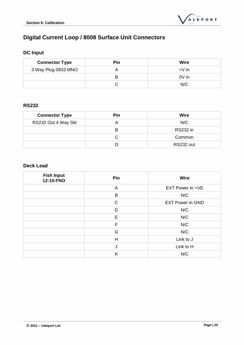
Digital Current Loop / 8008 Surface Unit Connectors
DC Input
Connector Type Pin Wire
3 Way Plug 0833 MNO A +V in
B 0V in
C N/C
RS232
Connector Type Pin Wire
RS232 Out 4 Way Skt A N/C
B RS232 in
C Common
D RS232 out
Deck Lead
Fish Input 12-10-FNO
Pin Wire
A EXT Power in +VE
B N/C
C EXT Power in GND
D N/C
E N/C
F N/C
G N/C
H Link to J
J Link to H
K N/C

Model 106 Self Recording/Direct Reading Current Meters Operating Manuel:
MANUAL-1390768583-1 | issue: 1.1
© 2021 – Valeport Ltd Page | 26
Appendix 3 Operation with DataLog x2
The 106 is supplied with DataLog x2 software for setup and data offload and display with a number of alphanumeric and graphical options.
Please see separate manual – 04008373a – DataLog x2 and Terminal x2 Operating Manual
Problems have arisen when the setup wizard is used and no changes are made, the ‘Finish’ key is not available – see below for a solution to this problem.
The final screen will show a summary of the commands that will be sent to the instrument.
If settings have not been changed, then no commands will be shown and the finish button is greyed out. Simply type a # into the command window and the Finish button will be available.
Section 6: Calibration
© 2021 – Valeport Ltd Page | 27
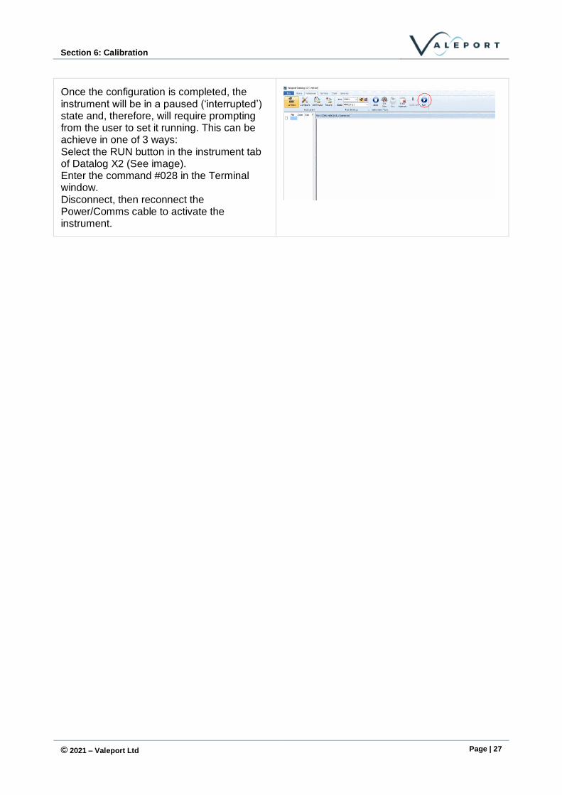
Once the configuration is completed, the instrument will be in a paused (‘interrupted’) state and, therefore, will require prompting from the user to set it running. This can be achieve in one of 3 ways: Select the RUN button in the instrument tab of Datalog X2 (See image). Enter the command #028 in the Terminal window. Disconnect, then reconnect the Power/Comms cable to activate the instrument.