model 039250-61201 copper inline audit tool, w/encoder
TRANSCRIPT

Model 039250-61201
COPPER INLINE AUDIT TOOL, W/ENCODER
Installation and Operating Manual
For assistance with the operation of this product,contact PCB Piezotronics, Inc.
Toll-free: 800-828-884024-hour SensorLine: 716-684-0001
Fax: 716-684-0987E-mail: [email protected]: www.pcb.com
The information contained in this document supersedes all similar information that
may be found elsewhere in this manual. Total Customer Satisfaction – PCB Piezotronics guarantees Total Customer Satisfaction. If, at any time, for any reason, you are not completely satisfied with any PCB product, PCB will repair, replace, or exchange it at no charge. You may also choose to have your purchase price refunded in lieu of the repair, replacement, or exchange of the product. Service – Due to the sophisticated nature of the sensors and associated instrumentation provided by PCB Piezotronics, user servicing or repair is not recommended and, if attempted, may void the factory warranty. Routine maintenance, such as the cleaning of electrical connectors, housings, and mounting surfaces with solutions and techniques that will not harm the physical material of construction, is acceptable. Caution should be observed to insure that liquids are not permitted to migrate into devices that are not hermetically sealed. Such devices should only be wiped with a dampened cloth and never submerged or have liquids poured upon them. Repair – In the event that equipment becomes damaged or ceases to operate, arrangements should be made to return the equipment to PCB Piezotronics for repair. User servicing or repair is not recommended and, if attempted, may void the factory warranty.
Calibration – Routine calibration of sensors and associated instrumentation is recommended as this helps build confidence in measurement accuracy and acquired data. Equipment calibration cycles are typically established by the users own quality regimen. When in doubt about a calibration cycle, a good “rule of thumb” is to recalibrate on an annual basis. It is also good practice to recalibrate after exposure to any severe temperature extreme, shock, load, or other environmental influence, or prior to any critical test. PCB Piezotronics maintains an ISO- 9001 certified metrology laboratory and offers calibration services, which are accredited by A2LA to ISO/IEC 17025, with full traceability to SI through N.I.S.T. In addition to the normally supplied calibration, special testing is also available, such as: sensitivity at elevated or cryogenic temperatures, phase response, extended high or low frequency response, extended range, leak testing, hydrostatic pressure testing, and others. For information on standard recalibration services or special testing, contact your local PCB Piezotronics distributor, sales representative, or factory customer service representative. Returning Equipment – Following these procedures will insure that your returned materials are handled in the most expedient manner. Before
Warranty, Service, Repair, and
Return Policies and Instructions
returning any equipment to PCB Piezotronics, contact your local distributor, sales representative, or factory customer service representative to obtain a Return Warranty, Service, Repair, and Return Policies and Instructions Materials Authorization (RMA) Number. This RMA number should be clearly marked on the outside of all package(s) and on the packing list(s) accompanying the shipment. A detailed account of the nature of the problem(s) being experienced with the equipment should also be included inside the package(s) containing any returned materials. A Purchase Order, included with the returned materials, will expedite the turn-around of serviced equipment. It is recommended to include authorization on the Purchase Order for PCB to proceed with any repairs, as long as they do not exceed 50% of the replacement cost of the returned item(s). PCB will provide a price quotation or replacement recommendation for any item whose repair costs would exceed 50% of replacement cost, or any item that is not economically feasible to repair. For routine calibration services, the Purchase Order should include authorization to proceed and return at current pricing, which can be obtained from a factory customer service representative. Warranty – All equipment and repair services provided by PCB Piezotronics, Inc. are covered by a limited warranty against defective material and workmanship for a period of one year from date of original purchase. Contact
PCB for a complete statement of our warranty. Expendable items, such as batteries and mounting hardware, are not covered by warranty. Mechanical damage to equipment due to improper use is not covered by warranty. Electronic circuitry failure caused by the introduction of unregulated or improper excitation power or electrostatic discharge is not covered by warranty. Contact Information – International customers should direct all inquiries to their local distributor or sales office. A complete list of distributors and offices can be found at www.pcb.com. Customers within the United States may contact their local sales representative or a factory customer service representative. A complete list of sales representatives can be found at www.pcb.com. Toll-free telephone numbers for a factory customer service representative, in the division responsible for this product, can be found on the title page at the front of this manual. Our ship to address and general contact numbers are: PCB Piezotronics, Inc. 3425 Walden Ave. Depew, NY14043 USA Toll-free: (800) 828-8840 24-hour SensorLineSM: (716) 684-0001 Website: www.pcb.com
E-mail: [email protected]
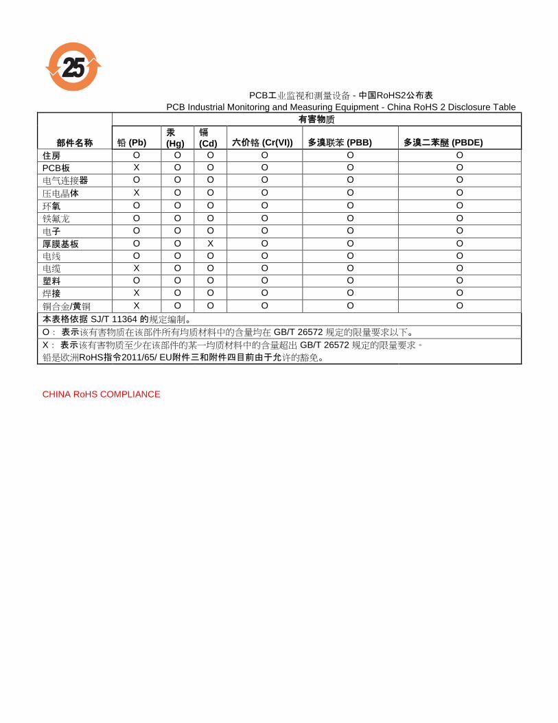
PCB工业监视和测量设备 - 中国RoHS2公布表
PCB Industrial Monitoring and Measuring Equipment - China RoHS 2 Disclosure Table
部件名称
有害物质
铅 (Pb) 汞
(Hg)
镉
(Cd) 六价铬 (Cr(VI)) 多溴联苯 (PBB) 多溴二苯醚 (PBDE)
住房 O O O O O O
PCB板 X O O O O O
电气连接器 O O O O O O
压电晶体 X O O O O O
环氧 O O O O O O
铁氟龙 O O O O O O
电子 O O O O O O
厚膜基板 O O X O O O
电线 O O O O O O
电缆 X O O O O O
塑料 O O O O O O
焊接 X O O O O O
铜合金/黄铜 X O O O O O
本表格依据 SJ/T 11364 的规定编制。
O: 表示该有害物质在该部件所有均质材料中的含量均在 GB/T 26572 规定的限量要求以下。
X: 表示该有害物质至少在该部件的某一均质材料中的含量超出 GB/T 26572 规定的限量要求。
铅是欧洲RoHS指令2011/65/ EU附件三和附件四目前由于允许的豁免。
CHINA RoHS COMPLIANCE
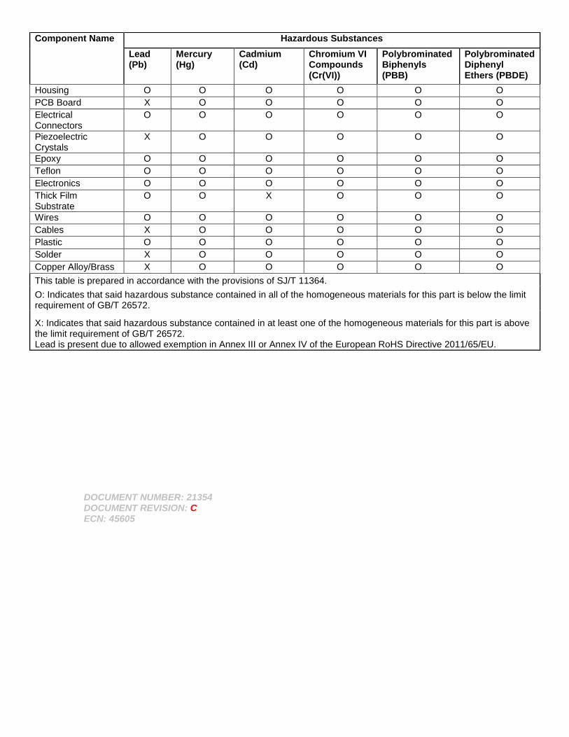
DOCUMENT NUMBER: 21354 DOCUMENT REVISION: C ECN: 45605
Component Name Hazardous Substances
Lead (Pb)
Mercury (Hg)
Cadmium (Cd)
Chromium VI Compounds (Cr(VI))
Polybrominated Biphenyls (PBB)
Polybrominated Diphenyl Ethers (PBDE)
Housing O O O O O O
PCB Board X O O O O O
Electrical Connectors
O O O O O O
Piezoelectric Crystals
X O O O O O
Epoxy O O O O O O
Teflon O O O O O O
Electronics O O O O O O
Thick Film Substrate
O O X O O O
Wires O O O O O O
Cables X O O O O O
Plastic O O O O O O
Solder X O O O O O
Copper Alloy/Brass X O O O O O
This table is prepared in accordance with the provisions of SJ/T 11364.
O: Indicates that said hazardous substance contained in all of the homogeneous materials for this part is below the limit requirement of GB/T 26572.
X: Indicates that said hazardous substance contained in at least one of the homogeneous materials for this part is above the limit requirement of GB/T 26572. Lead is present due to allowed exemption in Annex III or Annex IV of the European RoHS Directive 2011/65/EU.
Model Number
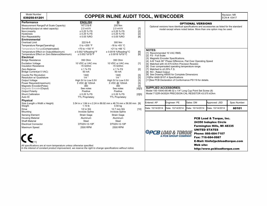
039250-61201 COPPER INLINE AUDIT TOOL, W/ENCODERRevision: NR
ECN #: 43417
Performance ENGLISH SI Measurement Range(Full Scale Capacity) 147.5 lb-ft 200 Nm
Sensitivity(output at rated capacity) 2.0 mV/V 2.0 mV/V [7]Non-Linearity ± 0.25 % FS ± 0.25 % FS [2]Hysteresis ± 0.25 % FS ± 0.25 % FS [2]
Non-Repeatability ≤ 0.05 %RO ≤ 0.05 %RO [8]
EnvironmentalOverload Limit 222 lb-ft 300 Nm
Temperature Range(Operating) 0 to +200 °F -18 to +93 °C
Temperature Range(Compensated) +70 to +150 °F +21 to +66 °C
Temperature Effect on Output(Maximum) ± 0.002 %Reading/°F ± 0.0018 %Reading/°C [6]Temperature Effect on Zero Balance(Maximum) ± 0.002 %FS/°F ± 0.0018 %FS/°C [6]
ElectricalBridge Resistance 350 Ohm 350 Ohm
Excitation Voltage 10 VDC or VAC rms 10 VDC or VAC rms [1]Insulation Resistance >5 GOhm >5 GOhm
Zero Balance ≤ 1 % FS ≤ 1 % FS [2]Bridge Current(at 5 VAC) 50 mA 50 mA
Counts Per Revolution 1440 1440 [3]Resolution w/ Quadrature 1/4 ° 1/4 ° [3]
Output Voltage High 5V to Low 0.5V High 5V to Low 0.5V [3]
Power Required(maximum) 5 VDC @ 120mA 5 VDC @ 120mA [3]Magnetic Encoder(Poles) 360 360 [3]Magnetic Encoder(Ouput) See notes See notes [4][3]
Output Polarity Positive Positive
Shunt Calibration ≤ 0.25 % FS ≤ 0.25 % FS [2][5]Auto ID TTL Proprietary TTL Proprietary
PhysicalSize (Length x Width x Height) 3.54 in x 1.84 in x 2.24 in 89.92 mm x 46.74 mm x 56.90 mm [9]Weight 1.10 lb 0.50 kg
Drive 1/2 in SQ 12.7 mm SQ [10]Mounting Involute Spline Involute Spline
Sensing Element Strain Gage Strain Gage
Housing Material Aluminum Aluminum
Shaft Material Steel Steel
Electrical Connector DT02H-12-10P DT02H-12-10P
Maximum Speed 2500 RPM 2500 RPM
All specifications are at room temperature unless otherwise specified.In the interest of constant product improvement, we reserve the right to change specifications without notice.
NOTES:[1] Recommended 10 VAC RMS.[2] FS - Full Scale.
[3] Magnetic Encoder Specifications.
[4] A-B Track 90° Phase Difference, Flat Over Operating Speed
[5] Matched with 43.575 kOhm Precision Resistor.[6] Over compensated operating temperature range.
[7] Matched to ±0.25% F.S.
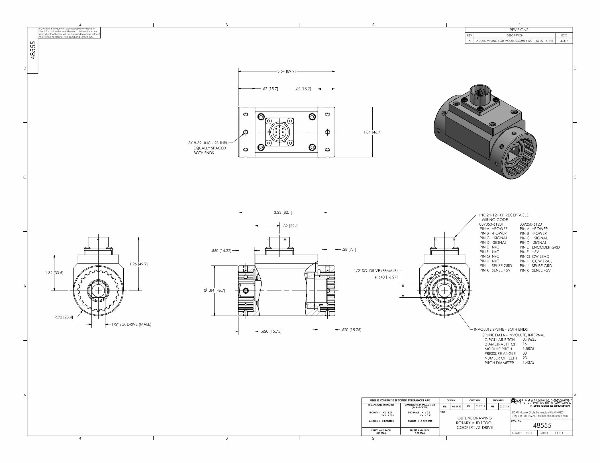
[8] RO - Rated Output.[9] See Drawing 48555 for Complete Dimensions
[10]Per ANSI B107.4 Specifications
[11]See PCB Declaration of Conformance PS119 for details.
SUPPLIED ACCESSORIES: Model 100-10043-80 #8-32 x 1/4" Long Cup Point Set Screw (8)
Model 7122R-04352A PRECISION CAL RESISTOR 43.575 kOhm
PCB Load & Torque, Inc.
24350 Indoplex Circle
Farmington Hills, MI 48335
UNITED STATES
Phone: 866-684-7107
Fax: 716-684-0987
E-Mail: [email protected]
Web site:
http://www.pcbloadtorque.com
[11]
OPTIONAL VERSIONSOptional versions have identical specifications and accessories as listed for the standard
model except where noted below. More than one option may be used.
Entered: AP Engineer: PE Sales: DM Approved: JSD Spec Number:
Date: 10/14/2014 Date: 10/14/2014 Date: 10/14/2014 Date: 10/14/2014 60101
1
1
2
2
3
3
4
4
A A
B B
C C
D D
DWG. NO.
SCALE: SHEET
DRAWN CHECKED ENGINEER
TITLE
UNLESS OTHERWISE SPECIFIED TOLERANCES ARE:
DIMENSIONS IN MILLIMETERS[ IN BRACKETS ]
ANGLES ` .5 DEGREES
24350 Indoplex Circle, Farmington Hills,MI 48335
(716) 684-0001 E-MAIL: [email protected]
DIMENSIONS IN INCHES
ANGLES ` .5 DEGREES
FILLETS AND RADII
.015 MAX
FILLETS AND RADII
0.38 MAX
OUTLINE DRAWING
485551 OF 1FULL
ROTARY AUDIT TOOL
COOPER 1/2" DRIVE
PTE 02.27.12
DECIMALS XX ±.01
XXX ±.005
DECIMALS X ± 0.3
XX ± 0.13
3.54 [89.9]
.62 [15.7].62 [15.7]
48
55
5PCB Load & Torque Inc. claims proprietary rights in
the information disclosed hereon. Neither it nor any
reproduction thereof will be disclosed to others without
the written consent of PCB Load and Torque Inc.
SPLINE DATA - INVOLUTE, INTERNAL
CIRCULAR PITCH
DIAMETRAL PITCH
MODULE PITCH
PRESSURE ANGLE
NUMBER OF TEETH
PITCH DIAMETER
0.19635
16
1.5875
30
23
1.4375
PIN A
PIN B
PIN C
PIN D
PIN E
PIN F
PIN G
PIN H
PIN J
PIN K
+POWER
-POWER
+SIGNAL
-SIGNAL
N/C
N/C
N/C
N/C
SENSE GRD
SENSE +5V
8-32 UNC - 2B8X THRU
EQUALLY SPACED
BOTH ENDS
REVISIONS
REV DESCRIPTION ECO
A ADDED WIRING FOR MODEL 039250-61201 - 09.29.14, PTE 43417
.28 [7.1]
.620 [15.75].620 [15.75]
1.84 [46.7]
n1.84 [46.7]
1/2" SQ. DRIVE (FEMALE)
x.640 [16.27]
1/2" SQ. DRIVE (MALE)
1.96 [49.9]
R.92 [23.4]
PTO2H-12-10P RECEPTACLE
- WIRING CODE -
039050-61201 039250-61201
INVOLUTE SPLINE - BOTH ENDS
1.32 [33.5]
.560 [14.22]
3.23 [82.1]
+POWER
-POWER
+SIGNAL
-SIGNAL
ENCODER GRD
+5V
CW LEAD
CCW TRAIL
SENSE GRD
SENSE +5V
PIN A
PIN B
PIN C
PIN D
PIN E
PIN F
PIN G
PIN H
PIN J
PIN K
.89 [22.6]
PTE 02.27.12 PTE 02.27.12

51678 RS Rotary Torque Transducer Manual_CE.doc 3/12/2012
Rotary Socket Wrench Torque Transducer
Installation and Operating Manual
For assistance with the operation of this product, contact:
RS Technologies Division of PCB Load & Torque, Inc.
Toll-Free in USA: 888-684-2894 24-hour SensorLineSM: 716-684-0001
Fax: 248-888-8266 E-mail: [email protected]
RS Technologies Division of PCB Load & Torque, Inc. � Toll-Free in USA 888-684-28947 � 716-684-0001 � www.pcbloadtorque.com
ROTARY SOCKET WRENCH TORQUE TRANSDUCER OPERATION MA NUAL
2
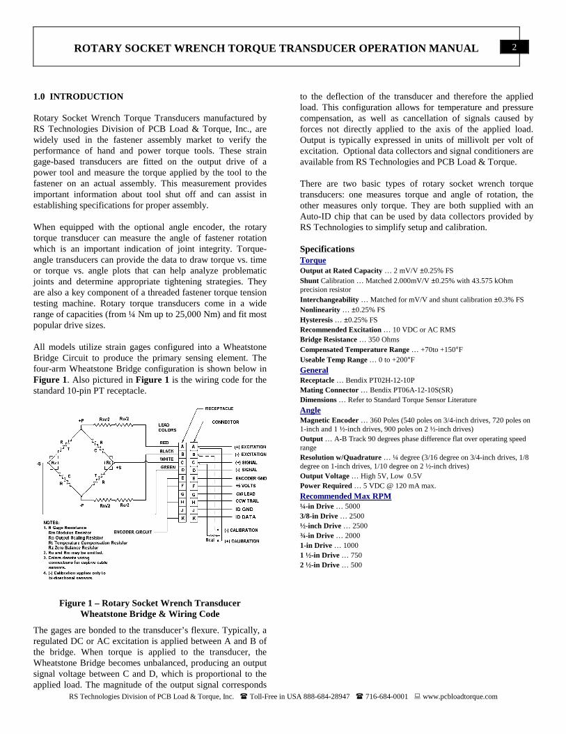
1.0 INTRODUCTION Rotary Socket Wrench Torque Transducers manufactured by RS Technologies Division of PCB Load & Torque, Inc., are widely used in the fastener assembly market to verify the performance of hand and power torque tools. These strain gage-based transducers are fitted on the output drive of a power tool and measure the torque applied by the tool to the fastener on an actual assembly. This measurement provides important information about tool shut off and can assist in establishing specifications for proper assembly. When equipped with the optional angle encoder, the rotary torque transducer can measure the angle of fastener rotation which is an important indication of joint integrity. Torque-angle transducers can provide the data to draw torque vs. time or torque vs. angle plots that can help analyze problematic joints and determine appropriate tightening strategies. They are also a key component of a threaded fastener torque tension testing machine. Rotary torque transducers come in a wide range of capacities (from ¼ Nm up to 25,000 Nm) and fit most popular drive sizes. All models utilize strain gages configured into a Wheatstone Bridge Circuit to produce the primary sensing element. The four-arm Wheatstone Bridge configuration is shown below in Figure 1. Also pictured in Figure 1 is the wiring code for the standard 10-pin PT receptacle.
Figure 1 – Rotary Socket Wrench Transducer
Wheatstone Bridge & Wiring Code
The gages are bonded to the transducer’s flexure. Typically, a regulated DC or AC excitation is applied between A and B of the bridge. When torque is applied to the transducer, the Wheatstone Bridge becomes unbalanced, producing an output signal voltage between C and D, which is proportional to the applied load. The magnitude of the output signal corresponds
to the deflection of the transducer and therefore the applied load. This configuration allows for temperature and pressure compensation, as well as cancellation of signals caused by forces not directly applied to the axis of the applied load. Output is typically expressed in units of millivolt per volt of excitation. Optional data collectors and signal conditioners are available from RS Technologies and PCB Load & Torque. There are two basic types of rotary socket wrench torque transducers: one measures torque and angle of rotation, the other measures only torque. They are both supplied with an Auto-ID chip that can be used by data collectors provided by RS Technologies to simplify setup and calibration. Specifications Torque Output at Rated Capacity … 2 mV/V ±0.25% FS Shunt Calibration … Matched 2.000mV/V ±0.25% with 43.575 kOhm precision resistor Interchangeability … Matched for mV/V and shunt calibration ±0.3% FS Nonlinearity … ±0.25% FS Hysteresis … ±0.25% FS Recommended Excitation … 10 VDC or AC RMS Bridge Resistance … 350 Ohms Compensated Temperature Range … +70to +150°F Useable Temp Range … 0 to +200°F
General Receptacle … Bendix PT02H-12-10P Mating Connector … Bendix PT06A-12-10S(SR) Dimensions … Refer to Standard Torque Sensor Literature
Angle Magnetic Encoder … 360 Poles (540 poles on 3/4-inch drives, 720 poles on 1-inch and 1 ½-inch drives, 900 poles on 2 ½-inch drives) Output … A-B Track 90 degrees phase difference flat over operating speed range Resolution w/Quadrature … ¼ degree (3/16 degree on 3/4-inch drives, 1/8 degree on 1-inch drives, 1/10 degree on 2 ½-inch drives) Output Voltage … High 5V, Low 0.5V Power Required … 5 VDC @ 120 mA max.
Recommended Max RPM ¼-in Drive … 5000 3/8-in Drive … 2500 ½-inch Drive … 2500 ¾-in Drive … 2000 1-in Drive … 1000 1 ½-in Drive … 750 2 ½-in Drive … 500
RS Technologies Division of PCB Load & Torque, Inc. � Toll-Free in USA 888-684-2894 � 716-684-0001 � www.pcbloadtorque.com
ROTARY SOCKET WRENCH TORQUE TRANSDUCER OPERATION MA NUAL
3
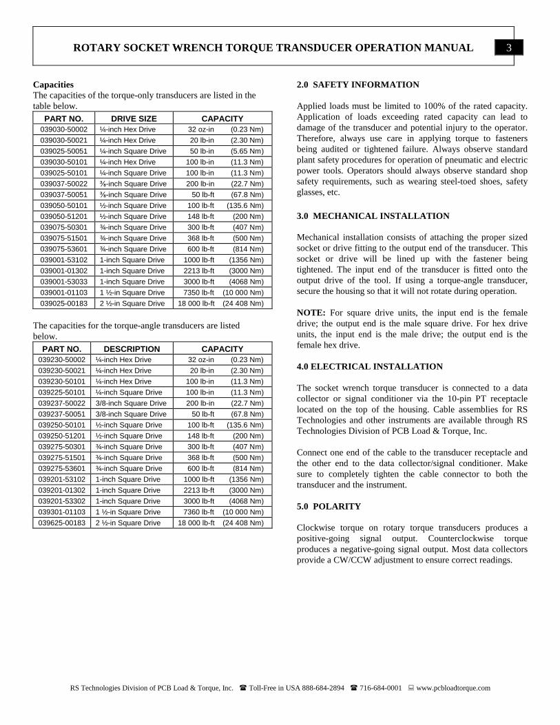
Capacities The capacities of the torque-only transducers are listed in the table below.
PART NO. DRIVE SIZE CAPACITY 039030-50002 ¼-inch Hex Drive 32 oz-in (0.23 Nm)
039030-50021 ¼-inch Hex Drive 20 lb-in (2.30 Nm)
039025-50051 ¼-inch Square Drive 50 lb-in (5.65 Nm)
039030-50101 ¼-inch Hex Drive 100 lb-in (11.3 Nm)
039025-50101 ¼-inch Square Drive 100 lb-in (11.3 Nm)
039037-50022 ⅜-inch Square Drive 200 lb-in (22.7 Nm)
039037-50051 ⅜-inch Square Drive 50 lb-ft (67.8 Nm)
039050-50101 ½-inch Square Drive 100 lb-ft (135.6 Nm)
039050-51201 ½-inch Square Drive 148 lb-ft (200 Nm)
039075-50301 ¾-inch Square Drive 300 lb-ft (407 Nm)
039075-51501 ¾-inch Square Drive 368 lb-ft (500 Nm)
039075-53601 ¾-inch Square Drive 600 lb-ft (814 Nm)
039001-53102 1-inch Square Drive 1000 lb-ft (1356 Nm)
039001-01302 1-inch Square Drive 2213 lb-ft (3000 Nm)
039001-53033 1-inch Square Drive 3000 lb-ft (4068 Nm)
039001-01103 1 ½-in Square Drive 7350 lb-ft (10 000 Nm)
039025-00183 2 ½-in Square Drive 18 000 lb-ft (24 408 Nm)
The capacities for the torque-angle transducers are listed below.
PART NO. DESCRIPTION CAPACITY 039230-50002 ¼-inch Hex Drive 32 oz-in (0.23 Nm)
039230-50021 ¼-inch Hex Drive 20 lb-in (2.30 Nm)
039230-50101 ¼-inch Hex Drive 100 lb-in (11.3 Nm)
039225-50101 ¼-inch Square Drive 100 lb-in (11.3 Nm)
039237-50022 3/8-inch Square Drive 200 lb-in (22.7 Nm)
039237-50051 3/8-inch Square Drive 50 lb-ft (67.8 Nm)
039250-50101 ½-inch Square Drive 100 lb-ft (135.6 Nm)
039250-51201 ½-inch Square Drive 148 lb-ft (200 Nm)
039275-50301 ¾-inch Square Drive 300 lb-ft (407 Nm)
039275-51501 ¾-inch Square Drive 368 lb-ft (500 Nm)
039275-53601 ¾-inch Square Drive 600 lb-ft (814 Nm)
039201-53102 1-inch Square Drive 1000 lb-ft (1356 Nm)
039201-01302 1-inch Square Drive 2213 lb-ft (3000 Nm)
039201-53302 1-inch Square Drive 3000 lb-ft (4068 Nm)
039301-01103 1 ½-in Square Drive 7360 lb-ft (10 000 Nm)
039625-00183 2 ½-in Square Drive 18 000 lb-ft (24 408 Nm)
2.0 SAFETY INFORMATION Applied loads must be limited to 100% of the rated capacity. Application of loads exceeding rated capacity can lead to damage of the transducer and potential injury to the operator. Therefore, always use care in applying torque to fasteners being audited or tightened failure. Always observe standard plant safety procedures for operation of pneumatic and electric power tools. Operators should always observe standard shop safety requirements, such as wearing steel-toed shoes, safety glasses, etc. 3.0 MECHANICAL INSTALLATION Mechanical installation consists of attaching the proper sized socket or drive fitting to the output end of the transducer. This socket or drive will be lined up with the fastener being tightened. The input end of the transducer is fitted onto the output drive of the tool. If using a torque-angle transducer, secure the housing so that it will not rotate during operation. NOTE: For square drive units, the input end is the female drive; the output end is the male square drive. For hex drive units, the input end is the male drive; the output end is the female hex drive. 4.0 ELECTRICAL INSTALLATION The socket wrench torque transducer is connected to a data collector or signal conditioner via the 10-pin PT receptacle located on the top of the housing. Cable assemblies for RS Technologies and other instruments are available through RS Technologies Division of PCB Load & Torque, Inc. Connect one end of the cable to the transducer receptacle and the other end to the data collector/signal conditioner. Make sure to completely tighten the cable connector to both the transducer and the instrument. 5.0 POLARITY Clockwise torque on rotary torque transducers produces a positive-going signal output. Counterclockwise torque produces a negative-going signal output. Most data collectors provide a CW/CCW adjustment to ensure correct readings.
RS Technologies Division of PCB Load & Torque, Inc. � Toll-Free in USA 888-684-2894 � 716-684-0001 � www.pcbloadtorque.com
ROTARY SOCKET WRENCH TORQUE TRANSDUCER OPERATION MA NUAL
4
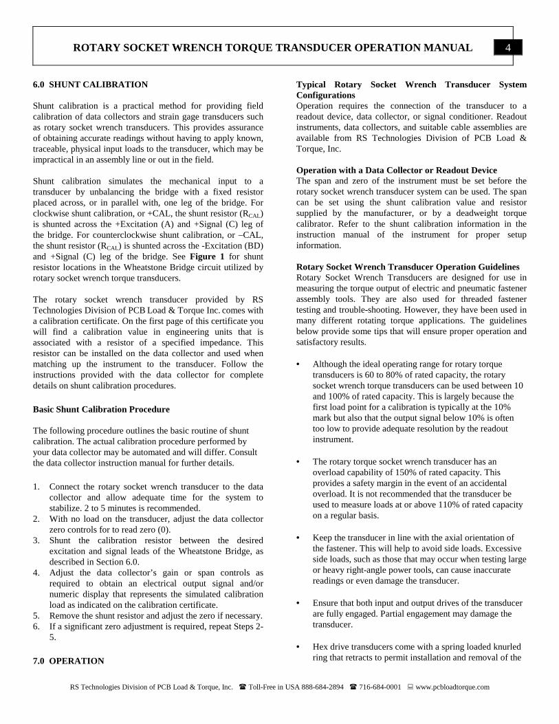
6.0 SHUNT CALIBRATION Shunt calibration is a practical method for providing field calibration of data collectors and strain gage transducers such as rotary socket wrench transducers. This provides assurance of obtaining accurate readings without having to apply known, traceable, physical input loads to the transducer, which may be impractical in an assembly line or out in the field. Shunt calibration simulates the mechanical input to a transducer by unbalancing the bridge with a fixed resistor placed across, or in parallel with, one leg of the bridge. For clockwise shunt calibration, or +CAL, the shunt resistor (RCAL) is shunted across the +Excitation (A) and +Signal (C) leg of the bridge. For counterclockwise shunt calibration, or –CAL, the shunt resistor (RCAL) is shunted across the -Excitation (BD) and +Signal (C) leg of the bridge. See Figure 1 for shunt resistor locations in the Wheatstone Bridge circuit utilized by rotary socket wrench torque transducers. The rotary socket wrench transducer provided by RS Technologies Division of PCB Load & Torque Inc. comes with a calibration certificate. On the first page of this certificate you will find a calibration value in engineering units that is associated with a resistor of a specified impedance. This resistor can be installed on the data collector and used when matching up the instrument to the transducer. Follow the instructions provided with the data collector for complete details on shunt calibration procedures.
Basic Shunt Calibration Procedure The following procedure outlines the basic routine of shunt calibration. The actual calibration procedure performed by your data collector may be automated and will differ. Consult the data collector instruction manual for further details. 1. Connect the rotary socket wrench transducer to the data
collector and allow adequate time for the system to stabilize. 2 to 5 minutes is recommended.
2. With no load on the transducer, adjust the data collector zero controls for to read zero (0).
3. Shunt the calibration resistor between the desired excitation and signal leads of the Wheatstone Bridge, as described in Section 6.0.
4. Adjust the data collector’s gain or span controls as required to obtain an electrical output signal and/or numeric display that represents the simulated calibration load as indicated on the calibration certificate.
5. Remove the shunt resistor and adjust the zero if necessary. 6. If a significant zero adjustment is required, repeat Steps 2-
5. 7.0 OPERATION
Typical Rotary Socket Wrench Transducer System Configurations Operation requires the connection of the transducer to a readout device, data collector, or signal conditioner. Readout instruments, data collectors, and suitable cable assemblies are available from RS Technologies Division of PCB Load & Torque, Inc. Operation with a Data Collector or Readout Device The span and zero of the instrument must be set before the rotary socket wrench transducer system can be used. The span can be set using the shunt calibration value and resistor supplied by the manufacturer, or by a deadweight torque calibrator. Refer to the shunt calibration information in the instruction manual of the instrument for proper setup information. Rotary Socket Wrench Transducer Operation Guidelines Rotary Socket Wrench Transducers are designed for use in measuring the torque output of electric and pneumatic fastener assembly tools. They are also used for threaded fastener testing and trouble-shooting. However, they have been used in many different rotating torque applications. The guidelines below provide some tips that will ensure proper operation and satisfactory results. • Although the ideal operating range for rotary torque
transducers is 60 to 80% of rated capacity, the rotary socket wrench torque transducers can be used between 10 and 100% of rated capacity. This is largely because the first load point for a calibration is typically at the 10% mark but also that the output signal below 10% is often too low to provide adequate resolution by the readout instrument.
• The rotary torque socket wrench transducer has an overload capability of 150% of rated capacity. This provides a safety margin in the event of an accidental overload. It is not recommended that the transducer be used to measure loads at or above 110% of rated capacity on a regular basis.
• Keep the transducer in line with the axial orientation of the fastener. This will help to avoid side loads. Excessive side loads, such as those that may occur when testing large or heavy right-angle power tools, can cause inaccurate readings or even damage the transducer.
• Ensure that both input and output drives of the transducer are fully engaged. Partial engagement may damage the transducer.
• Hex drive transducers come with a spring loaded knurled ring that retracts to permit installation and removal of the
RS Technologies Division of PCB Load & Torque, Inc. � Toll-Free in USA 888-684-2894 � 716-684-0001 � www.pcbloadtorque.com
ROTARY SOCKET WRENCH TORQUE TRANSDUCER OPERATION MA NUAL
5
drive bit. Make sure that both ends are fully engaged before use.
• When it’s necessary to use a drive adapter, use as few as possible to avoid side loads.
• When using a transducer with an angle encoder, make sure that the housing is held secure to ensure best angle measurement accuracy.
• Rotary socket wrench torque transducers are good for use with standard pneumatic tools, impulse tools, and electric power tools. Do NOT use with “impact” pneumatic tools.
8.0 TROUBLESHOOTING When having difficulty operating the rotary socket wrench transducer, refer to the following checklist. No output ����No power ����Loose or dirty connections ����Open circuit or short ����Faulty or improper wiring ����No torque applied
Erratic or Improper Readings ����Excitation voltage drift ����Electrical noise ����Loose fixturing ����Open circuit or short ����Improper load applied ����Cable too long Blinking Display ����Overload condition ����Open circuit Zero Balance ����Load applied to transducer ����Overloaded or side-loaded transducer ����Open circuit ����Improper electrical connections Zero Shift ����Fixture preload ����Faulty or improper wiring ����Improper zero taken Zero Drift ����Unconditioned power supply ����Open circuit or short ����Loose wiring ����RFI/EMI interface ����Temperature change
Damaged or Deformed Equipment ����Improper use Error Analysis PCB Load & Torque, Inc. typically supplies accuracy information on its products in the form of individual errors (see specification sheet). For rotary socket wrench transducers they are: Non-Linearity, Hysteresis, and Non-Repeatability. The customer can combine these individual errors to establish the maximum possible error for the measurement or just examine the applicable individual error. If the transducer is used for increasing torque measurement only, ignore the Hysteresis error. If the torque measurement is near the full rated capacity, the linearity error can be ignored. If the capability exists to correct the data through linearization-fit or a look-up-table, the error in the measurement can be minimized. A sophisticated user can get rid of all the errors except for the non-repeatability error in the measurement. If problems persist, contact PCB Load & Torque for technical assistance. 9.0 MAINTENANCE The rotary socket wrench transducers provided by RS Technologies Division of PCB Load & Torque Inc. are made of durable materials, and are intended for industrial use. However, routine maintenance, such as cleaning of electrical connectors, housings, and square drives with solutions and techniques that will not harm the physical material of construction is acceptable. The rotary socket wrench transducers should only be wiped with a damp cloth and never submerged or have liquids poured on them. NOTE: There are no user-serviceable components in rotary socket wrench torque transducers provided by RS Technologies division of PCB Load & Torque Inc. Removing the cover on the unit will void the warranty.
# # #

RS Technologies Division of PCB Load & Torque, Inc. � Toll-Free in USA 888-684-2894 � 716-684-0001 � www.pcbloadtorque.com
ROTARY SOCKET WRENCH TORQUE TRANSDUCER OPERATION MA NUAL
6
MANUAL NUMBER: 51678 MANUAL REVISION: NR ECN NUMBER: 38209