mode shift keying for reconfigurable mimo antennas
TRANSCRIPT
320 IEEE TRANSACTIONS ON VEHICULAR TECHNOLOGY, VOL. 68, NO. 1, JANUARY 2019
Mode Shift Keying for Reconfigurable MIMOAntennas: Performance Analysis and
Antenna DesignMehedi Hasan, Israfil Bahceci , Member, IEEE, Md. Asaduzzaman Towfiq , Tolga M. Duman , Fellow, IEEE,
and Bedri A. Cetiner , Senior Member, IEEE
Abstract—Space-shift-keying (SSK) and spatial modulation(SM) enable multiple antenna transmission systems to convey in-formation on antenna indices. While SSK/SM helps reduce thenumber of radio frequency (RF) chains, large numbers of anten-nas and low spatial correlations are required to achieve high datarates. This work investigates the use and design of multifunctionalreconfigurable antennas (MRAs) for SSK/SM based transmissionwhere a single-element MRA generates large numbers of modes.To enhance legacy SSK/SM performance while reducing RF hard-ware complexity, we propose single- and multi-carrier antennamode-shift keying (MoSK) and mode modulation (MoM) schemesfacilitated by MRAs. Based on an error probability analysis, wedetermine criteria for MRA design and mode set selection suitablefor MoSK/MoM. We also develop two MRA designs and investigatetheir performances over Rayleigh fading channels. We argue thatby creating MRA modes with low pattern correlations, channelcorrelations can be reduced to improve the detection performance.Extensive simulations demonstrate that MoSK/MoM performanceexceeds that of SSK/SM along with significant complexity reduc-tion. For instance, a single-carrier MoSK/MoM using a single MRAwith 8 modes achieves about 2 dB gain compared to legacy SSK/SMrequiring 8 antennas, and by multi-carrier MoSK/MoM using 4subcarriers, an MRA with 32 modes can attain an error rate per-formance comparable to this single-carrier system.
Index Terms—Antenna diversity, MIMO systems, reconfig-urable antennas, modulation, multipath channels.
I. INTRODUCTION
S PACE-shift-keying (SSK) [1]–[3] and spatial modulation(SM) [4], [5] are multiple antenna transmission techniques
Manuscript received March 18, 2018; revised August 8, 2018; accepted Oc-tober 3, 2018. Date of publication October 30, 2018; date of current versionJanuary 15, 2019. This work was supported in part by AFOSR under Grant FA9550-15-1-0040DEF and in part by Defense University Research Instrumen-tation Program under Grant FA9550-16-1-0352. The review of this paper wascoordinated by Prof. T. Kuerner. (Corresponding author: Israfil Bahceci.)
M. Hasan is with the Marvell Semiconductor, Santa Clara, CA 95054 USA(e-mail:,[email protected]).
I. Bahceci is with the Ericsson Canada, Inc., Kanata, ON K2K 2V6, Canada(e-mail:,[email protected]).
Md. A. Towfiq is with the i5 Technologies, Inc., Logan, UT 84341 USA(e-mail:,[email protected]).
T. M. Duman is with the Department of Electrical and Electronics En-gineering, Bilkent University, Ankara 06800, Turkey (e-mail:, [email protected]).
B. A. Cetiner is with the Department of Electrical and Computer En-gineering, Utah State University, Logan, UT 84321 USA (e-mail:, [email protected]).
Color versions of one or more of the figures in this paper are available onlineat http://ieeexplore.ieee.org.
Digital Object Identifier 10.1109/TVT.2018.2878768
that rely on modulating the spatial channel to transfer informa-tion over a wireless link. In SSK, the information bits determineone of M transmit antenna elements for transmission. With SM,the information bits determine both an antenna index and a con-stellation signal that is transmitted on the selected antenna. Thereceiver attempts to decode the information bits by recoveringthe underlying antenna index (and the constellation signal incase of SM) using the received signal’s spatial signature. Themain advantage of SSK/SM is the reduction of the number ofradio-frequency (RF) chains for multiple antenna transmissionswhile preserving the diversity gain, i.e., SSK/SM promises sim-plified hardware with only a small performance trade-off. How-ever, a number of implementation issues exist. For example, inthe case of pulse shaping with a period longer than the symboltime, one may need more RF chains to perform SSK modulation[2]. Furthermore, in order to increase the data rate, one needsto increase the number of antennas significantly. This makesSSK/SM suitable for only large units such as base stations oraccess points. In addition, high spatial correlations among thechannels from different transmit elements result in performancedegradation [1].
In this paper, we investigate and analyze the SSK and SMfor multiple input multiple output (MIMO) systems comprisingof multifunctional reconfigurable antenna (MRA) elements. Asingle MRA element, capable of dynamically changing its prop-erties (radiation pattern, polarization, frequency), a.k.a. modes,provides important degrees of freedom that can be used to sig-nificantly enhance the system performance [6]–[11]. Recently,a reconfigurable antenna (RA) based SSK solution has beenreported in the literature [12], demonstrating that SSK with po-larization reconfigurable antennas performs better than legacySSK for a line-of-sight multipath propagation model. In [12],the additional degrees of freedom have been obtained by chang-ing the Rician K-factor and the polarization correlation coef-ficient. However, for rich scattering environments where thepropagation is typically non-line of sight (NLOS), one needsto utilize additional RA properties to make use of spatial diver-sity. With this motivation, here we concentrate on both the useand design of MRAs for SSK/SM applications. Towards thisgoal, we perform a comprehensive analysis of MRAs withinthis context and present two different MRA designs. Associ-ated with each excited mode of an MRA that is selected fortransmission, a different spatial channel is created. Consideringa multipath rich scattering propagation medium, we proposeto employ radiation pattern reconfigurable antennas for whichalong with the pattern itself the polarization property over thepattern is reconfigurable, resulting in a large number of modes.
0018-9545 © 2018 IEEE. Personal use is permitted, but republication/redistribution requires IEEE permission.See http://www.ieee.org/publications standards/publications/rights/index.html for more information.

HASAN et al.: MODE SHIFT KEYING FOR RECONFIGURABLE MIMO ANTENNAS: PERFORMANCE ANALYSIS AND ANTENNA DESIGN 321
Each of the modes is designed in such a way that the associatedradiation patterns result in low spatial correlations. We namethe proposed schemes mode shift keying (MoSK) and modemodulation (MoM).
We develop union bounds on the pairwise error probability(PEP) that relates the underlying radiation patterns, i.e., modes,to the overall error rate performance. We then investigate theMRA design problem and employ the performance analysis re-sults to determine the relevant optimization criteria so as toselect the antenna modes suitable for MoSK/MoM based trans-missions. We also develop two different MRA designs basedon parasitic tuning [13]. Different from earlier MRA designs,this work aims at determining MRA architectures capable ofgenerating a large number of modes resulting in low pattern cor-relations. We note that the proposed MoSK and MoM schemesestablish a similar form of media-based modulation techniqueproposed in [14] where Khandani investigates the impact of in-tentional variation of RF properties (permittivity, resistivity, andpermeability) of a medium placed nearby the transmitter. In ourscheme, the antenna element properties are varied based on theparasitic tuning approach to create different spatial signaturesfrom the same antenna position. Note that this is not possiblewith legacy SSK schemes as the number of antennas needs tobe increased. Since PIN diodes with typical switching times onthe order of 10 nanoseconds [15] are employed for the proposedparasitic tuning, very high baud rates can be attained.
Another contribution of this work is the extension ofMoSK/MoM schemes to wideband transmissions. Even thoughSSK and SM have received a considerable attention over thelast decade [16]–[19], there are only a limited number of worksfor wideband transmissions [20]. Legacy SSK/SM proposed formulti-carrier (MC) transmission schemes assume availabilityof multiple RF chains as opposed to the single-carrier (SC)SSK schemes [21]. However, with a single RF chain, widebandSSK becomes inefficient as one would still need to increasethe number of antenna elements to improve the transmissionrates [1]. In [20], Sugiura and Hanzo propose an SC based SM-MIMO suitable for broadband communications. Although theproposed method attains a near-capacity performance with theaid of a three-stage concatenated architecture, it is still basedon SC transmissions. In our work, we propose MC based wide-band MoSK and MoM schemes. For the proposed scheme, ouranalysis on the error probability shows that, thanks to the jointmode and frequency selectivity of the channel, one can increasethe number of antenna modes, and hence, the transmission ratesover wideband channels considerably.
To summarize, the contributions of this work are threefold:(i) novel design of MRAs optimized for MoSK and MoMbased transmissions and performance analysis, (ii) feasible andefficient MoSK and MoM schemes for MC based widebandcommunications and associated performance analysis, and (iii)extensive numerical examples based on practical MRA designsin realistic settings demonstrating the advantages of the pro-posed schemes. The proposed design is suitable for a genericpropagation environment, i.e., it is not limited to LOS propaga-tion as in [12]. In addition, since the proposed MRA system cangenerate a large number of modes, in response to the underlyingpropagation medium characteristics, one can perform a modesubset selection to determine the best set of modes suitablefor MoSK and MoM. Since legacy SSK/SM schemes employMIMO systems that are fixed by design, they do not have suchflexibility, and their performance is limited by the underlyingpropagation medium and the resulting spatial channel statis-
Fig. 1. MIMO channel with M transmit and N receive MRA elements. μm :MRA-m mode, hn ,m : channel gain from antenna-m to antenna-n, sm : sig-nal from MRA-m, rn : signal received by MRA-n. Control lines enable thegeneration of the modes.
tics. Numerical examples using two different practical MRAdesigns indicate that the proposed MoSK and MoM schemesfor both narrowband and wideband transmission achieve su-perior performance compared to the legacy SSK/SM schemes.For example, with SC MoSK/MoM, our MRA designs utilizing8 modes achieve up to 2 dB SNR gains compared to legacySSK/SM schemes requiring 8 antenna elements. Furthermore,the proposed MC MoSK/MoM schemes utilizing a 32-modeMRA over 4 subcarriers achieve similar error rates compared toSC MoSK/MoM schemes with 8 modes, that is, the widebandMoSK/MoM design is effective in exploiting both frequencyand radiation pattern diversity. Note that an equivalent legacySSK/SM scheme requires 32 antenna elements to achieve thesame data rates, indicating that large reductions in complexitywith the MoSK/MoM schemes are possible.
The rest of the paper is organized as follows. In the nextsection, we describe the system and channel models for MRAsystems. In Section III, the newly proposed MoSK and MoMschemes along with analytical calculations of error probabil-ities are presented. MoSK/MoM for wideband transmission isexplained in Section IV. Section V provides details of the practi-cal MRAs designed by full-wave electromagnetic analysis [22].Simulation results for both narrowband and wideband transmis-sions are provided in Section VI. Finally, we conclude the paperin Section VII.
II. CHANNEL AND SYSTEM MODEL
A. MIMO Channel With MRAs
Let us consider a wireless MIMO channel with M trans-mit and N receive MRA elements, as illustrated in Fig. 1. Forbrevity, we assume that the receive antenna elements are fixedto some configuration state and are not varied throughout thetransmissions. Let �f(θ, φ, μ) denote the complex far-field radi-ation pattern where μ ∈ {1, 2, . . . , Lμ} represents the antennamode. For MIMO systems comprising of MRAs (MR-MIMO)with M MRA elements, the complex E-field pattern for the mthelement can be expressed as
�fm (θ, φ, μ) = fθ,m (θ, φ, μ)�eθ + fφ,m (θ, φ, μ)�eφ (1)
where fθ and fφ are the θ and φ components of the radiatedelectric field along the directions of �eθ and �eφ unit vectors,respectively. The variable μ ∈ M = {1, . . . , Lμ} denotes the
322 IEEE TRANSACTIONS ON VEHICULAR TECHNOLOGY, VOL. 68, NO. 1, JANUARY 2019
mode index of antenna-m, m = 1, . . . , M . Since each elementcan have a different configuration resulting in a different radia-tion pattern, the channel impulse response will be a function ofthe antenna radiation pattern, i.e., the mode. Assuming that thereceiver configuration is fixed, we denote the channel impulseresponse from MRA-m to MRA-n as hn,m (μ) where μ empha-sizes the dependency of the channel realization on the transmitMRA mode. Using the beamspace representation in a double-directional MIMO channel model [23], [24], one can show thatthe impact of transmit antenna pattern can be decoupled fromall other propagation related terms as follows [25]
hn,m (μ) = αHμ xn,m (2)
where αμ = [αμ,1 . . . αμ,F ] represents the F ≤ Lμ synthesiscoefficients for the radiation pattern �f(θ, φ, μ), μ = 1, . . . , Lμ ,and xn,m is the F × 1 column vector obtained by projecting thechannel gains onto the F basis patterns and represents the effectof antenna orientations, receive antenna pattern, propagationdelays, steering vectors, and the path gains. (·)H denotes theconjugate transpose.
We assume that only one of the available antennas is activatedduring the transmission at any given time. Then, we have theoverall channel as an N × 1 vector hm (μ) with m indicatingthe transmit antenna index. We define two covariance matrices:(i) the covariance matrix for a fixed mode between the channelsfrom the transmit antennas m1 and m2 to the receive antennasas
Ψm 1,m 2 = E[hm 1(μ)hm 2(μ)H ], (3)
and (ii) the covariance matrix from the transmit antenna-m tothe receive antennas for different antenna modes, μi and μj :
Υμi ,μj= E[hm (μi)hm (μj )H ]. (4)
For narrowband transmission, the input-output relation can beexpressed as
r(μ) =√
Phm (μ)s + n (5)
where r(μ) is the received signal vector r(μ) = [r1(μ) · · ·rN (μ)]T , s is the transmitted waveform normalized to unit en-ergy, P is the transmit power, and n = [n1 · · ·nN ] denotes theadditive white Gaussian noise (AWGN) with the zero-meancircularly symmetric complex Gaussian distribution having avariance of σ2/2 per dimension. Assuming the presence of alarge number of paths with no LOS components, and using thewell known central limit theorem, the channel matrix exhibitsa multivariate circularly symmetric complex Gaussian distribu-tion, i.e., in what follows, we assume that the channel undergoesspatially and temporally correlated Rayleigh fading.
B. SSK/SM With Single-Mode MIMO
Assume a legacy MIMO antenna for which μ is fixed for eachantenna-m. For SSK, the transmitted bits determine the activeantenna index m from which a waveform signal is transmitted.With SM transmission, additional information is sent using asignal from a constellation S = {s1, . . . , sQ} where Q = 2r
is the number of symbols in the constellation with r denotingthe number of bits per symbol. Hence, SM with Q = 1 ands1 denoting the waveform reduces to SSK modulation. Themaximum likelihood decoder (MLD) with ideal channel stateinformation to detect the antenna index (and also the symbol in
case of SM) is given by [4]
(m, s) = arg minm∈{1,...,M },s∈S‖r(μ) −√
Phm (μ)s‖ (6)
where ‖ · ‖ denotes the Euclidean norm. Assuming that the chan-nel is fixed for a transmitted waveform s normalized to unitenergy, Chernoff bound on the pairwise error probability (PEP)of the MLD can be expressed as [26]
P (m → m, s → s|hm (μ), s) ≤
exp(− P
4σ2‖shm (μ) − shm (μ)‖2
F
). (7)
With Q = 1, we obtain the SSK modulation for which the boundon PEP averaged over the Rayleigh fading channel statistics canbe obtained from (7) as [27]
P (m → m) ≤∣∣∣∣IN +
P
4σ2Ψm/m
∣∣∣∣−1
(8)
where
Ψm/m = Ψm,m + Ψm ,m − Ψm,m − Ψm ,m (9)
is the covariance matrix of the channel difference between an-tenna m and m.
III. MODE SHIFT KEYING AND MODE MODULATION
A. Constellation
The legacy SSK/SM schemes for a MIMO system and theproposed MoSK and MoM schemes for a single MRA systemare shown in Figs. 2(a) and 2(b), respectively. The SSK/SMscheme for which the antenna configuration is fixed and in-dependent from the transmitted information [2], [4], [5] re-quires multiple antenna elements and a single-pole multi-throwRF switch to perform antenna selection, whereas the proposedMoSK/MoM scheme requires only a single MRA elementwhere the information bits determine the antenna mode foreach channel use. The baseband part of both MoSK/MoM andlegacy SSK/SM scheme are similar to each other. The SSK/SM(MoSK/MoM) Operation Enabler block decides on the underly-ing (i) SSK/SM (MoSK/MoM) method and (ii) waveform gener-ator (SSK/MoSK)/modulator (SM/MoM), based on the channelstate information feedback and/or some system parameters. ForMoSK/MoM, by selecting La modes out of the available Lμ ,the transmitter can map R = log2(La) bits as the index of theselected modes. For ease of exposition, here, we assume thatthe La is a power of two, i.e., La = 2R , where R is an integerdenoting the number of bits transmitted per MRA mode. In Ta-ble I, we provide examples of MoSK and MoM mapping withfour selected modes. In the case of MoM, for this example, aBPSK symbol is carried on top of MoSK.
The maximum data rate for SSK/SM and MoSK/MoM canbe expressed as log2(X )+log2(Q)
Ts wwhere X = M for SSK and
X = La for MoSK, and Q = 2r is the constellation size (withr = 0 for SSK and r ≥ 1 for SM/MoM) [28]. Tsw is the switch-ing time for the single-pole multi-throw (SPMT) switches forthe SSK/SM and PIN diode control switches for MoSK/MoM.The SPMT switching time can range from 20 nanoseconds to300 micro seconds [28], [29] and it increases as the number ofantennas increase. The PIN diode switching time for MRAs canbe as low as 4 to 10 nanoseconds [30] depending on reversebias levels of the PIN driver circuitry. Hence, one would expect5 times or more throughput with MoSK/MoM when M = La .

HASAN et al.: MODE SHIFT KEYING FOR RECONFIGURABLE MIMO ANTENNAS: PERFORMANCE ANALYSIS AND ANTENNA DESIGN 323
Fig. 2. Comparison of (a) legacy SSK/SM scheme with M antenna elements where each antenna has one fixed mode, and (b) proposed MoSK/MoM schemeusing a single MRA capable of generating La ≥ M modes.
TABLE IAN EXAMPLE OF MOSK AND MOM MAPPING
For a general spatial modulation scheme with M antennas,Lμ modes per antenna, and a signal constellation with Q el-ements, the transmitted bits select the antenna index, antennamode index and constellation signal. The MLD for this schemecan be expressed as
(m, μ, s) = arg minm∈{1,...,M },μ∈{1,...,Lμ },s∈S
‖r(μ) −√
Phm (μ)s‖.(10)
Note that the transmission according to (5) with fixed μ alongwith the MLD in (10) reduces to the legacy SSK schemes em-ploying non-reconfigurable antennas as in (6). Furthermore, thecase with M = 1 and Q = 1 corresponds to MoSK while thecase with M = 1, Q > 1 corresponds to the MoM proposedabove.
B. Performance Gains With MoSK/MoM
From (8) and (9), it is seen that the performance of a legacySSK system is limited by the original MIMO design, e.g., fixedinterelement spacing and array geometry. The proposed MoSKand MoM systems create a flexible single-element antenna plat-form whose modes can be adapted to the multipath propagationmedium for improved performance. To that end, for M = La ,i.e., for SSK and MoSK schemes with identical rates, let usdefine the relative gain between the SSK and MoSK as
ζ =
∑m �=m d(m, m)−1∑
μ �=μ d(μ, μ)−1(11)
where d(m, m)−1 = |Ψm/m | and d(μ, μ)−1 = |Υμ/μ | with
Υμ/μ = Υμ,μ + Υμ ,μ − Υμ,μ − Υμ ,μ . (12)
A large ζ indicates that the performance loss of MoSK due tocorrelations among different antenna modes will be lower com-pared to that of SSK due to spatial channel correlations amongthe channels from different antenna elements. This metric isbased on an upper bound on the symbol error rates as developedin the Appendix.
C. Antenna Mode Set Construction for MoSK/MoM
With an RA system, the loss in the channel gains due tothe correlations can be reduced by selecting the RA modes forwhich d(μ, μ)−1 is minimized. This provides additional degreesof freedom for optimized designs compared to the legacy SSKschemes where the MIMO structure is fixed. Assuming that thecovariance matrices for all the modes are available, using (11),we obtain the following mode design rule
M∗a = arg min
Ma ⊆M
∑μ �=μ,(μ,μ)∈Ma
d(μ, μ)−1
s.t. M = {μ : tr(Υμ,μ) ≥ ζth} (13)
where the search space of the modes are constrained to those re-sulting in an average SNR of at least Pζth/σ2 with ζth denotinga threshold parameter. While this criterion aims to determinethe set of modes minimizing the average decoding error, thesearch is computationally complex if Lμ is large. Observingthat larger values of d(μ, μ) result in smaller error probabili-ties, we propose an iterative (greedy) mode design approach asfollows:
μ∗l = arg max
μ∈M,μ �=μk ,k=1,...,l−1
(min
i=1,...,l−1d(μi, μ)
),
s.t. μ∗1 = arg max
μ∈Mtr(Υμ,μ), (14)
where μl denotes the mode selected at iteration-l, l = 1, . . . , La ,the minimization inside the parenthesis ensures that the newlyselected antenna mode at iteration-l maximizes the smallestpossible d(μi, μ), and finally the trace condition sets the initialmode to the one achieving the highest SNR among all availablemodes.
Note that the above design approach assumes that the channelcovariance matrices are known. The impact of MRA elementradiation pattern on the channel difference covariance matrix

324 IEEE TRANSACTIONS ON VEHICULAR TECHNOLOGY, VOL. 68, NO. 1, JANUARY 2019
can be explicitly obtained by substituting the channel model in(2) to (12) and after some manipulation:
ΥΔ = (IN ⊗ (αHμ − αH
μ ))R (IN ⊗ (αμ − αμ)) (15)
where [R](n1−1)N +f1,(n2−1)N +f2= [Rn1,n2 ]f1,f2 , f1, f2 ∈ {1,
. . . , F}, n1, n2 ∈ {1, . . . , N} with Rn1,n2 = E[xn1,m xHn2,m
].Under the rich scattering assumption, the extended covariancematrix R becomes positive-definite. Using (15) in the Chernoffbound, we arrive at
P (μ → μ) ≤∣∣∣∣IN F +
P
4σ2(IN ⊗ Ξμ,μ)R
∣∣∣∣−1
(16)
where Ξμ,μ = (αμ − αμ)(αHμ − αH
μ ) is the pattern differenceproduct matrix. Observing that IN ⊗ Ξμ,μ has N nonzero iden-tical eigenvalues ‖αμ − αμ‖2, R is positive definite, and theproduct B(μ, μ) = (IN ⊗ Ξμ,μ)R has N nonzero eigenvalues,using Theorems 1 and 2 in [31], we can write
‖αμ − αμ‖2NN∏
n=1
λN F −n+1(R) ≤N∏
n=1
λn (B(μ, μ))(R)
≤ ‖αμ − αμ‖2NN∏
n=1
λn (R), (17)
where λi(A) denotes the ith largest eigenvalue of the Hermitianmatrix A. Hence, we can write a lower bound on d(μ, μ) as
d(μ, μ) ≥ ‖αμ − αμ‖2NN∏
n=1
λN F −n+1(R). (18)
Notice that the bounds decouple the impact of antenna patternfrom that of R allowing us to perform mode optimization basedonly on the radiation patterns. Thus, a suboptimal mode designbased on the optimization in (13) can be expressed as
M∗a = arg min
Ma ⊆M
∑μ �=μ,(μ,μ)∈Ma
‖αμ − αμ‖−2N (19)
s.t. M :{
μ :∫∫
R‖�f(θ, φ, μ)‖2 sin(θ)dθdφ ≥ γth
}(20)
where the set of modes in the search space M is constrained tothose having the most of the radiated power within the region{(θ, φ) ∈ R}. This region may be obtained from the knowledgeof the azimuth and elevation angle spreads of the underlyingpropagation environment.
Observing that maxμ,μ dl(μ, μ) = minμ,μ �{αHμ αμ}, the it-
erative design of (14) can be simplified to
μ∗l = arg min
μ∈M,μ �=μk ,k=1,...,l−1
(max
i=1,...,l−1�{αH
μ αμ})
,
s.t. μ1 = arg maxμ∈M
‖�f(θ0, φ0, μ)‖, (21)
for l = 1, . . . , La , where the search space M is again selectedaccording to (20). For the initial mode, (θ0, φ0) can be chosenfrom a set of direction of interest for antenna coverage. This de-sign ensures that the active antenna modes include those havingthe least correlations amongst each other while their radiationpatterns cover the angular spread region of interest.
The Chernoff bound in (16) along with the product bounds in(17) also clarify that the error performance is dominated by the
antenna mode pairs having the smallest Euclidean distance be-tween the corresponding radiation patterns. Assuming identicaltotal radiated power for each antenna mode, i.e., ‖αμ‖2 = P0,for μ = 1, . . . , Lμ , we can express the smallest Euclidean dis-tance criteria in terms of the normalized pattern correlation
ρi,j =|αH
μiαμj
|‖αμi
‖‖αμj‖ (22)
between the antenna modes μi and μj . This observation can beemployed to optimize the radiation patterns of Lμ modes result-ing from the MRA design for MoSK/MoM, where the modesof the MRA shall have as small pattern correlations as possi-ble to maximize the smallest distance between the underlyingradiation patterns.
IV. MOSK/MOM FOR WIDEBAND TRANSMISSION
5G and beyond systems heavily rely on MIMO and widebandcommunications in the form of multicarrier (MC) transmissions(e.g., MIMO-OFDM) [32], [33]. Spatial modulation is thereforecritical for various 5G applications, especially when the designcosts for MIMO systems become formidable. The MoSK/MoMschemes create cost-effective alternatives for MC systems wherethe RAs can create vector channel states (over frequency andantenna modes) and can improve the detection of the underlyingmode with almost no hardware complexity increase. To analyzethe MoSK/MoM performance for this case, let us assume awideband transmission with K subcarriers. The signal model in(5) can be extended to the MC case by stacking the K N × 1column vectors into matrices as
R(μ) =√
PH(μ)S + N (23)
where R(μ) = [r1(μ) · · · rK (μ)] is the N × K received signalmatrix, H = [h1(μ) · · ·hK (μ)] is the N × K channel matrixfor MRA mode-μ, S = diag(s, . . . , s) and N = [n1 · · ·nK ] isAWGN matrix. The Chernoff bound on the PEP for the MLDin this case can be obtained as
P (μ → μ|H(μ),H(μ))
≤ exp
(− P
4σ2
K∑k=1
‖hk (μ) − hk (μ)‖2F
). (24)
Let the subcarrier spacing be Δf Hz, and assume that the chan-nel has a coherence bandwidth of Wc = �Δf , with � denot-ing the number of subcarriers within the coherence bandwidth,while the overall transmission bandwidth, (denoted by) WB , ismuch higher than the coherence bandwidth, i.e., Wc WB .We assume that the channel is block fading such that the totaltransmission band consists of K independently fading coher-ence blocks, i.e., WB = KWc .
We consider two different transmission scenarios: (i) sub-band transmission with frequency interleaving, and (ii) whole-band transmission. For the former case, assuming a subcarriershuffling using a uniform interleaver, the subcarriers assignedto the recipient become almost independent as long as the num-ber of subcarriers in the subband is at most K. Hence, assumingthat such an interleaving is possible, the joint probability densityfunction can be expressed as the product of individual probabil-ity density functions, and the PEP upper bound averaged over

HASAN et al.: MODE SHIFT KEYING FOR RECONFIGURABLE MIMO ANTENNAS: PERFORMANCE ANALYSIS AND ANTENNA DESIGN 325
the channel statistics can be obtained as,
PSB (μ → μ) ≤K∏
k=1
∣∣∣∣IN +P
4σ2Υμ/μ,k
∣∣∣∣−1
(25)
where Υμ/μ,k is the covariance matrix of the channel differencevector at the subcarrier k. For the whole-band transmission, asimilar PEP analysis results in
PW B (μ → μ) ≤K∏
k=1
∣∣∣∣IN +P�
4σ2Υμ/μ,k
∣∣∣∣−1
(26)
where Υμ/μ,k in this case refers to the covariance matrix of thechannel for the kth coherence block. It is seen that decoding theantenna mode using a larger number of channels that are inde-pendent from each other, the PEP will become smaller, whichis expected due to the availability of the additional frequencydiversity. This implies that the number of modes to convey in-formation can be increased to achieve the same PEP, and thus,the data rates can be increased. It is also seen that if the fre-quency selectivity of the channel is higher, i.e., for smaller �,a larger number of modes can be employed for MoSK/MoM.Note that with legacy SSK schemes using legacy antennas withfixed properties, wideband transmission is very inefficient andmay be impractical as one has to increase the number of antennaelements to increase the data rate.
The PEP bound for MoM using MC transmission can simi-larly be obtained as
P (μ → μ,S → S) ≤K∏
k=1
∣∣∣∣IN +Pβ
4σ2Φμ/μ,k
∣∣∣∣−1
(27)
where S = diag(s1, . . . , sk ) and S = diag(s1, . . . , sk ) denotethe constellation signals from S transmitted on the subcarrier-k,and Φμ/μ,k is the covariance matrix of skhk (μ) − skhk (μ).In (27), β = 1 and β = � for the subband and whole-bandtransmission, respectively.
V. MRA DESIGN AND OPTIMIZATION FOR MOSK/MOM
We next develop two practical MRAs suitable forMoSK/MoM. We consider parasitic coupling based MRA tech-nology where a driven antenna element is coupled with a recon-figurable parasitic layer where the surface geometry of this layer,which consists of metallic pixels interconnected by switches, ismodified by means of on-off switching [11], [13], [34]. Us-ing low-cost PIN diode switches with 1–3 volts of actuationvoltage and switching time of less than 10 nanoseconds [15]provides a highly fast reconfigurability feature that is suitablefor MoSK/MoM requiring very short switching times. The cri-teria for the design of MRAs for MoSK/MoM scheme differfrom those of legacy MRA design in that, in addition to therequired radiation pattern directivities, one would need to en-sure that the resulting set of achievable radiation patterns are asmuch uncorrelated from each other as possible. Such a designcan be realized by the MRA design methodology reported in[35] where the antenna modes are designed such that certainpolarizations and radiation patterns can be achieved. For theMoSK/MoM, we impose additional criteria to determine the setof switch states that can create a set of radiation pattern functionsoptimizing the outcome of mode selection rules (19) or (21). Tothis end, here, two different MRA designs capable of producing
Fig. 3. A generic MRA based on parasitic layer coupling. Both active antennalayer and parasitic layer can be reconfigurable. By setting the state of theswitches [b1 . . . b7], the radiation pattern and the polarization of the antenna canbe changed as desired.
a large number of radiation patterns with various shapes andpolarizations operating in the 5 GHz band are developed. Thedifferences between the two designs are on the antenna feed cir-cuitry, and in the distribution and the number of parasitic pixelelements used.
A. Parasitic Layer Based MRAs
An MRA based on a parasitic layer reconfiguration mech-anism consists of two main parts, namely, the driven activeantenna layer and the reconfigurable parasitic layer (see Fig. 3).The parasitic layer, which is located in the reactive field regionof the driven antenna, has a surface typically comprised of elec-trically small metallic patches, i.e., pixels, interconnected byRF switches. This surface is called a reconfigurable parasiticpixel surface of which geometry can be modified by activatinga specific switch configuration. Corresponding to each recon-figurable parasitic pixel surface geometry, there exists vary-ing degree of mutual coupling taking place between the drivenand parasitic layers, which is responsible for producing eachantenna mode where each mode may have different polariza-tion, radiation pattern and resonance frequency. The parasiticlayer based reconfiguration mechanism provides some signifi-cant advantages compared to the usual approach, which relieson modifying the geometry of the driven active antenna region[6]. The interconnecting switches along with biasing networkplaced within the active antenna region pose serious designchallenges such as high RF losses and power handling prob-lems resulting from the intense currents in the switches. On theother hand, parasitic layer approach usually keeps the activeantenna region unmodified, where reconfiguration capabilitiesare provided by the reconfigurable pixel layer, which has nophysical interconnection to the active antenna region. Thus theproblems associated with high RF losses and power handlingcapabilities are alleviated. Moreover, this approach takes ad-vantage of existing antenna designs and is compatible with awide variety of antenna architectures. Additionally, it offersadvantages in terms of integration capabilities useful for de-veloping sophisticated MRA architectures with high degree ofreconfigurability.
As it is well known, multi-antenna transmission schemes suchas MoSK/MoM necessitate the correlation between legacy an-tenna elements to be small (� 0.6), which can typically beachieved by spatially separating antennas with large enoughdistances (≈ λ/2 with λ denoting the wavelength), using

326 IEEE TRANSACTIONS ON VEHICULAR TECHNOLOGY, VOL. 68, NO. 1, JANUARY 2019
co-located antennas with patterns that are orthogonal to eachother or both [1], [24]. As a single MRA element is capableof producing a large number of antenna modes, we are inter-ested in MRA designs providing highly uncorrelated modes,which has been the main design criteria adopted in develop-ing the two MRA designs explained below. The orthogonalityamong the antenna modes can be accomplished by using pat-terns that are different in terms of their polarization propertiesand the three dimensional geometrical shape of the pattern it-self. It is worth noting that the polarization property of a givenantenna mode may change significantly over its radiation pat-tern �f(θ, φ, μ). At the same time providing good impedancematching along with high realized gain values for all the modesof interest at the design frequency is required. Both our MRAdesigns are capable of providing large number of modes withthe aforementioned properties with trade-offs in the complexityof parasitic layer and the RF feed circuitry driving the activeantenna.
B. MRA Design I: Simple Driven Patch Antenna With 3 × 3Parasitic Pixels
This MRA design, Design I, consists of a driven patch an-tenna fed by a coaxial cable and a parasitic layer of whichupper surface, reconfigurable parasitic pixel surface, has a gridof 3 × 3 electrically small squared-shaped metallic pixels. Theschematic of the MRA with critical design parameters are givenin Fig. 4(a). Notice that an air layer between driven antennaand parasitic layers is employed taking advantage of its low-loss nature. This design is similar to the one presented in [36]with the main difference being in the feed circuitry (coaxialvs. microstrip) and the frequency band of operation (5 GHz vs.2.4 GHz). Also, while in [36], the MRA is designed solely toprovide beam-steering capabilities with the highest realized gainvalues in few specific directions, the main design criteria in thiswork is to provide as large number of modes as possible withthe highest degree of decorrelation among them. For example,while the design problem for the MRA in [36] is to determineonly a few modes, the current design problem is to determineseveral tens of modes. The MRA designs producing the desiredmodes is performed by the full-wave electromagnetic analy-sis tool HFSS [22], used in conjunction with multi-objectivegenetic algorithm (GA) optimization. Design I compared to thenext MRA design, Design II, given below, relies on a more com-plex parasitic layer, i.e., 3 × 3 pixels with 12 interconnecting RFswitches, while employing a much simpler RF feed circuitry,i.e., single coaxial cable, in producing the desired modes withradiation patterns of various 3-D shapes and polarizations. Wenote that this MRA design is based on the one in [36], which wasfabricated and measured with good agreement between simu-lations and measurements. Switch integration, biasing circuitryand fabrication processes are similar to the one given in [36],and thereby, omitted here.
C. MRA Design II: Polarization Agile Driven Patch With2 × 4 Pixels
The overall architecture of this MRA design, Design II, issimilar to that of Design I (see Fig. 4(b)). This design employs asimpler reconfigurable parasitic pixel surface, where 2 × 4 pix-els with only 6 interconnecting switches are used. However, toobtain a similar number of highly decorrelated modes as gen-
Fig. 4. Parasitic coupling based MRA designs for 5 GHz band, dx,p anddy ,p denote the size of rectangular metallic pixels, dx,a and dy ,a denote thesize of driven patch antenna. (a) Design I: 3 × 3 pixel elements interconnectedwith 12 switches, dm denote the separation between the pixel surface and thedriven patch antenna. This antenna can attain 4096 modes. (b) Design II: Dual-polarized MRA capable of 5 different polarizations including linear (x−, y−,the slanted linear), right hand and left hand circular polarizations. This antennacan attain 320 different modes.
erated by Design I, Design II needs to employ a more complexRF feed circuitry. This consists of two RF ports used in con-junction with a reconfigurable directional coupler circuit [37],which enables the driven antenna to generate two orthogonal lin-ear polarizations (x− and y−), slanted linear polarization, andtwo orthogonal circular polarizations (right-hand CP and left-hand CP). Therefore, with a simple parasitic layer, the desireddecorrelated modes can be obtained. The complexity is traded-off between parasitic layer and RF feed circuitry in DesignsI and II. Notice that in Design I, the coaxial-fed driven patchantenna only produces a single linear polarization. However,the complexity introduced in the parasitic layer still enables usto obtain large number of decorrelated modes due to differentpolarizations and geometrical shapes of the radiation pattern.
Depending on the targeted modes of operations and otherconstraints required by the specific application, Design I orDesign II can alternatively be used. In general, the complexityintroduced at the RF feed circuitry would result in more systemlevel cost and reduced gain due to RF losses as compared tothe case where the complexity was introduced at the parasitic

HASAN et al.: MODE SHIFT KEYING FOR RECONFIGURABLE MIMO ANTENNAS: PERFORMANCE ANALYSIS AND ANTENNA DESIGN 327
TABLE IICRITICAL DESIGN PARAMETERS (IN mm)
layer. It is also worth noting that if the design goal is limited tobeam-steering capability in a few specific directions, then theDesign II with a simple single RF feed (i.e., a single microstripfeed) can be suitable, and thus provides simplicity advantagescompared to Design I.
D. Critical Design Parameters for MoSK/MoM
The values of critical design parameters for Design I and IIare presented in Table II. The simulated reflection coefficientsof various modes of operation with common bandwidths (BWs)for both MRAs are given in Fig. 5. Maintaining a common BWwhile configuring the radiation patterns of an MRA is one of themost critical design tasks. As seen from Figs. 5(a) and 5(b), theintersections of the individual reflection coefficients indicate acommon BW of 130 MHz and 90 MHz for MRA Design I andMRA Design II, respectively.
Next, let us analyze the pattern correlation performance asdefined in (2). Let αμr
denote the synthesis coefficients of thefixed element E-field pattern �f(θ, φ, μr ), of the receive antenna.The resulting set of MRA modes shall have E-field patterns suchthat (i) |αH
μiαμr
| ≥ pth , ∀i, so that polarization mismatch, pth ,
is sufficiently low, and (ii) |αHμi
αμj| ≤ ρ so that the channel
spatial signatures to differentiate the transmitted MoSK sym-bols are as diverse as possible. Using a full-wave EM analysistool [22], several modes of operation are obtained for each of theMRA designs proposed above. For Design I, there exist 4096available modes, therefore a GA based search is performed todetermine appropriate modes for MoSK modulation. Design IIallows us to generate 5 different set of polarizations from thedriven antenna. Therefore, there exist 2v (v = 6 being the num-ber of interconnecting switches) different E-field shapes for eachpolarization type, which results in a total of 320 different modesof operations.
The empirical cumulative distribution functions (CDF) of thepairwise normalized pattern correlation between the antennamodes achieved by Designs I and II are depicted in Fig. 6(a).The figure depicts the results for two approaches: (i) randomselection of 32 modes out of all available modes, and (ii) se-lection of 32 modes minimizing the sum of pairwise patterncorrelation values. Thus, in each case, 496 different mode pairsexist. It is seen that the optimized modes of both designs includeantenna modes that can attain small correlations. For Design I,a GA based optimization is performed to determine the opti-mized modes out of all 4096 modes available. Design II hasonly 320 different modes of operation and a random searchbased optimization is performed to obtain the best 32 modes.With Design II, smaller pattern correlations have been observedeven though the number of mode pairs with lower correlationsis less than that achieved by Design I. For example, from theCDF curves indicating the number of mode pairs with a corre-lation coefficient less than some threshold, it is seen that, about60% of the associated mode pairs (e.g., 300 mode pairs) have
Fig. 5. Simulated reflection coefficients of the MRAs. (a) Design I.(b) Design II.
correlation magnitudes of less than 0.6 for Design I, while it isabout 48% (e.g., 240 pairs) for Design II.
The relationship between the pairwise-pattern correlation andthe resulting performance difference based on (11) is illustratedin Fig. 6(b). Here, the underlying set of best La ∈ {2, 4, 8}modes for MoSK are selected from the 32 optimized patternssuch that the sum of pairwise pattern correlation values is mini-mized. For La = 2, 4, an exhaustive search is performed, whilefor La = 8, a random search based optimization is employed.In the figure, ρw denotes the pairwise pattern correlation withthe highest magnitude among all
(La
2
)pairs. The values of ζ
are obtained for an urban-micro B1 channel [38] (please seeSection VI for simulation setup). It is seen from the ζ valuesthat both MRA designs provide La = 2, 4 modes with signifi-cantly improved error rate performance compared to the legacySSK scheme employing dipole arrays. For La = 8, the unionbound predicts a comparable MoSK performance with legacySSK. With 8 modes, MRA I can achieve ζ = 0.4 dB, i.e., im-plying a slightly better performance, whereas for MRA 2, wehave ζ = −3.1, i.e., a slightly worse performance compared tothe legacy SSK. Nevertheless, the MoSK scheme will require

328 IEEE TRANSACTIONS ON VEHICULAR TECHNOLOGY, VOL. 68, NO. 1, JANUARY 2019
Fig. 6. (a) The CDF of normalized correlation coefficients for MRA E-field patterns for Designs I and II. Correlation performances for two cases are depicted:(1) random design, (2) optimized design for MoSK according to the minimization of sum of pattern correlation between the selected modes for MoSK. For bothdesigns, 32 modes are determined for MoSK. (b) Relation between the pairwise pattern correlation (ρw ), M/La , and ζ [from union bound analysis in (11)].
Fig. 7. Radiation patterns for 4 modes corresponding to La = 4 case in 6(b) for MRA I.
significantly lower hardware complexity due to use of a sin-gle reconfigurable antenna element instead of M = 8 elementsalong with the complicated RF switching circuitry.
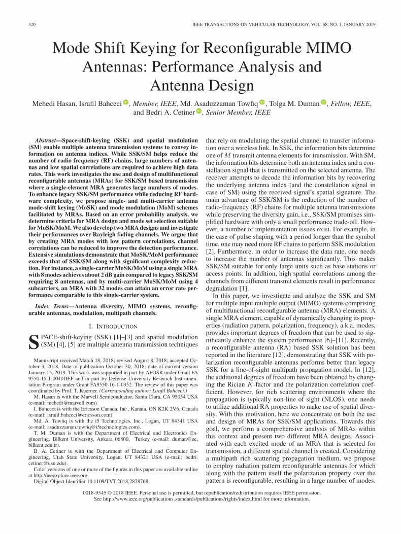
The normalized radiation patterns for the La = 4 case in 6(b)are depicted in Figs. 7 and 8 for MRA I and II, respectively.For MRA I, the low-correlation among radiation patterns aremainly achieved in the spatial domain. For MRA II, the patternin Fig. 8(a) is +x polarized while the ones in (b)–(d) are +ypolarized, thereby, resulting in very low correlation with them.The low correlation among the three +y polarized modes inFig. 8 is achieved in the spatial domain.
VI. NUMERICAL RESULTS
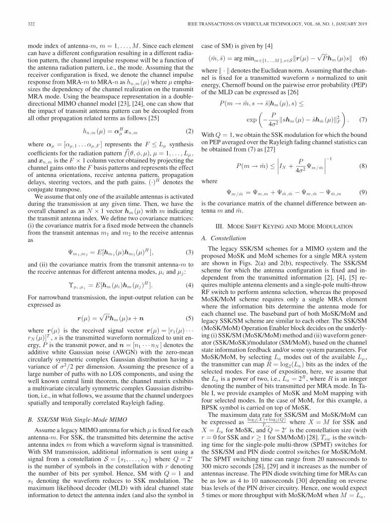
We next study the performance of proposed MoSK/MoMschemes with both MRA designs via numerical examples. Thetransmitter for legacy SSK/SM and the proposed MoSK/MoMschemes along with the receiver system that is common toboth transmission schemes are illustrated in Figs. 9(a), 9(b)and 9(c), respectively. In case of legacy SSK/SM, a MIMO an-tenna with M dipole elements separated by λ/2 are assumed(linear array) for which the antenna module occupies an area of(M − 1)λ/2 × λ/2. For the proposed MoSK/MoM schemes, asingle transmit MRA element (with a dimension of λ/2 × λ/2)
with Lμ modes is considered and the radiation patterns areobtained by full-wave EM analyses [22]. The values of the un-derlying parameters are specified for each example separately.The MIMO receiver has a 2− element crossed-dipole arraywith λ/2 interelement spacing, e.g., two ±45◦-slanted dipolesamounting to N = 4 dipole elements. As seen in Fig. 9(a), aSPMT switch is required to switch among the dipole elements.For the MoSK/MoM scheme, this SPMT is removed and PINdiode switch control is employed to switch among the differentMRA modes. The channel is modeled using a 3D double di-rectional MIMO channel [39], [40] modified for the underlyingMR-MIMO systems. For a fair comparison, the channel poweraveraged over all antenna modes is normalized to unity, e.g.,
1Lμ
∑Lμ
μ=1 E(|hm (μ)|2) = 1, and the average signal to noise ra-
tio is defined as P/σ2.
A. PEP Analysis and MRA Design for MoSK
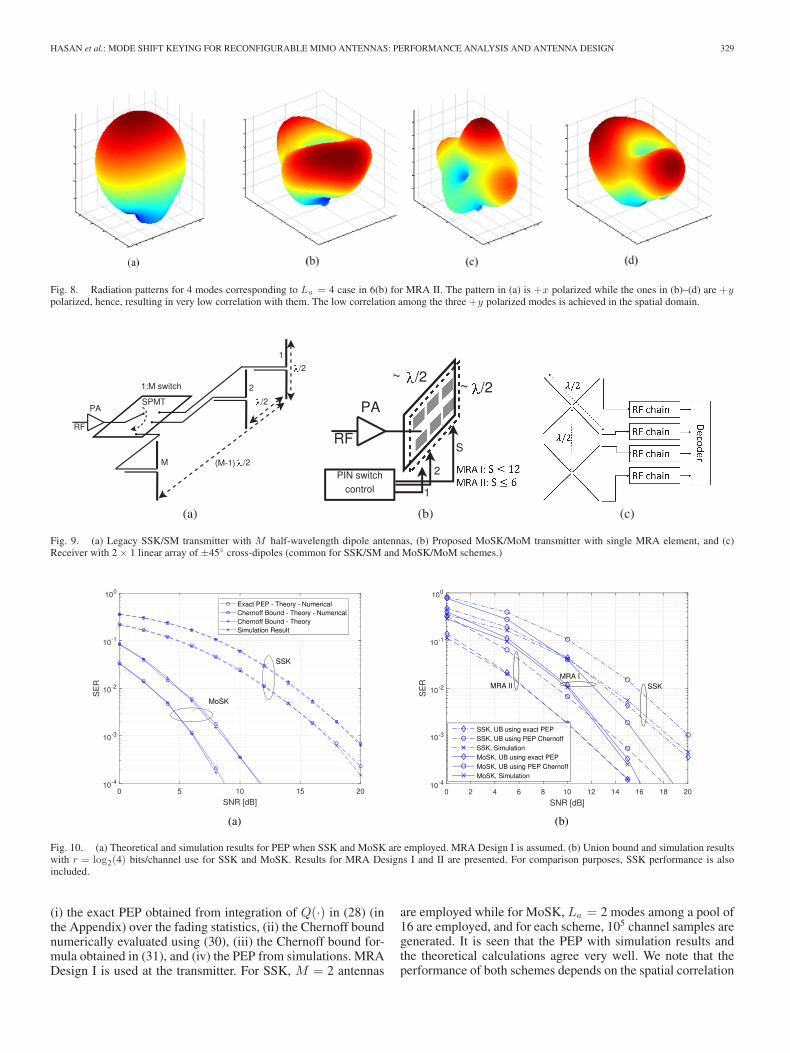
Let us first study the theoretical analysis by means of numer-ical calculations. Since the MC PEP analysis follows similarlyas the one for SC case, for brevity, we limit the discussion hereto the SC case. In Figs. 10(a) and 10(b), the PEP and the sym-bol error probability results are depicted for MoSK and SSKschemes. For both SSK and MoSK schemes, Fig. 10(a) shows
HASAN et al.: MODE SHIFT KEYING FOR RECONFIGURABLE MIMO ANTENNAS: PERFORMANCE ANALYSIS AND ANTENNA DESIGN 329
Fig. 8. Radiation patterns for 4 modes corresponding to La = 4 case in 6(b) for MRA II. The pattern in (a) is +x polarized while the ones in (b)–(d) are +ypolarized, hence, resulting in very low correlation with them. The low correlation among the three +y polarized modes is achieved in the spatial domain.
Fig. 9. (a) Legacy SSK/SM transmitter with M half-wavelength dipole antennas, (b) Proposed MoSK/MoM transmitter with single MRA element, and (c)Receiver with 2 × 1 linear array of ±45◦ cross-dipoles (common for SSK/SM and MoSK/MoM schemes.)
Fig. 10. (a) Theoretical and simulation results for PEP when SSK and MoSK are employed. MRA Design I is assumed. (b) Union bound and simulation resultswith r = log2(4) bits/channel use for SSK and MoSK. Results for MRA Designs I and II are presented. For comparison purposes, SSK performance is alsoincluded.
(i) the exact PEP obtained from integration of Q(·) in (28) (inthe Appendix) over the fading statistics, (ii) the Chernoff boundnumerically evaluated using (30), (iii) the Chernoff bound for-mula obtained in (31), and (iv) the PEP from simulations. MRADesign I is used at the transmitter. For SSK, M = 2 antennas
are employed while for MoSK, La = 2 modes among a pool of16 are employed, and for each scheme, 105 channel samples aregenerated. It is seen that the PEP with simulation results andthe theoretical calculations agree very well. We note that theperformance of both schemes depends on the spatial correlation
330 IEEE TRANSACTIONS ON VEHICULAR TECHNOLOGY, VOL. 68, NO. 1, JANUARY 2019
Fig. 11. MoSK performance with different design methods for (a) MRA Design I and (b) MRA Design II.
between the associated channels. In this example, the selectedmode pair for MoSK results in significantly lower correlationcompared to that of the SSK scheme with λ/2 interelement spac-ing between the antenna elements, thus achieving a significantSNR gain.
In Fig. 10(b), the union bound results are provided for SSKwith M = 4 transmit antennas, and for MoSK with Lμ = 4.For comparison purposes, we also plot the symbol error rates(SERs) obtained from simulations. The results for both MRAdesigns are depicted. It is again observed that the theoreticallyevaluated expressions are in line with the symbol error proba-bilities obtained from simulations. It is also seen that the unionbound using the Q-function based PEPs are very tight. Theperformance-complexity trade-off is also clear from the SERresults for MRA Designs I and II. We also note that, for lowSNR values, the SER difference between SSK and MoSK issmall. This is due to the fact that, at small SNRs, the thermalnoise (AWGN) is more dominant factor for the system perfor-mance, and hence, we see a comparatively smaller performanceimprovement. For higher SNRs, channel correlation becomesthe dominant factor and the diverse set of MRA modes can beutilized to increase the channel diversity.
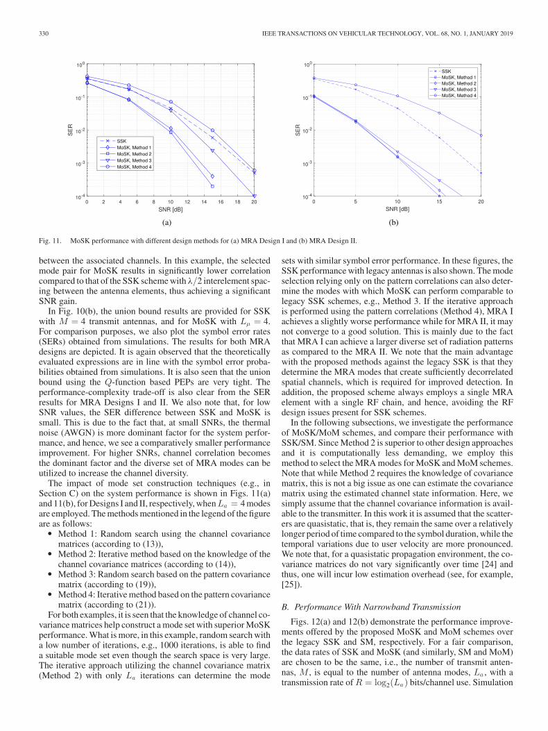
The impact of mode set construction techniques (e.g., inSection C) on the system performance is shown in Figs. 11(a)and 11(b), for Designs I and II, respectively, when La = 4 modesare employed. The methods mentioned in the legend of the figureare as follows:
� Method 1: Random search using the channel covariancematrices (according to (13)),
� Method 2: Iterative method based on the knowledge of thechannel covariance matrices (according to (14)),
� Method 3: Random search based on the pattern covariancematrix (according to (19)),
� Method 4: Iterative method based on the pattern covariancematrix (according to (21)).
For both examples, it is seen that the knowledge of channel co-variance matrices help construct a mode set with superior MoSKperformance. What is more, in this example, random search witha low number of iterations, e.g., 1000 iterations, is able to finda suitable mode set even though the search space is very large.The iterative approach utilizing the channel covariance matrix(Method 2) with only La iterations can determine the mode
sets with similar symbol error performance. In these figures, theSSK performance with legacy antennas is also shown. The modeselection relying only on the pattern correlations can also deter-mine the modes with which MoSK can perform comparable tolegacy SSK schemes, e.g., Method 3. If the iterative approachis performed using the pattern correlations (Method 4), MRA Iachieves a slightly worse performance while for MRA II, it maynot converge to a good solution. This is mainly due to the factthat MRA I can achieve a larger diverse set of radiation patternsas compared to the MRA II. We note that the main advantagewith the proposed methods against the legacy SSK is that theydetermine the MRA modes that create sufficiently decorrelatedspatial channels, which is required for improved detection. Inaddition, the proposed scheme always employs a single MRAelement with a single RF chain, and hence, avoiding the RFdesign issues present for SSK schemes.
In the following subsections, we investigate the performanceof MoSK/MoM schemes, and compare their performance withSSK/SM. Since Method 2 is superior to other design approachesand it is computationally less demanding, we employ thismethod to select the MRA modes for MoSK and MoM schemes.Note that while Method 2 requires the knowledge of covariancematrix, this is not a big issue as one can estimate the covariancematrix using the estimated channel state information. Here, wesimply assume that the channel covariance information is avail-able to the transmitter. In this work it is assumed that the scatter-ers are quasistatic, that is, they remain the same over a relativelylonger period of time compared to the symbol duration, while thetemporal variations due to user velocity are more pronounced.We note that, for a quasistatic propagation environment, the co-variance matrices do not vary significantly over time [24] andthus, one will incur low estimation overhead (see, for example,[25]).
B. Performance With Narrowband Transmission
Figs. 12(a) and 12(b) demonstrate the performance improve-ments offered by the proposed MoSK and MoM schemes overthe legacy SSK and SM, respectively. For a fair comparison,the data rates of SSK and MoSK (and similarly, SM and MoM)are chosen to be the same, i.e., the number of transmit anten-nas, M , is equal to the number of antenna modes, La , with atransmission rate of R = log2(La) bits/channel use. Simulation
HASAN et al.: MODE SHIFT KEYING FOR RECONFIGURABLE MIMO ANTENNAS: PERFORMANCE ANALYSIS AND ANTENNA DESIGN 331
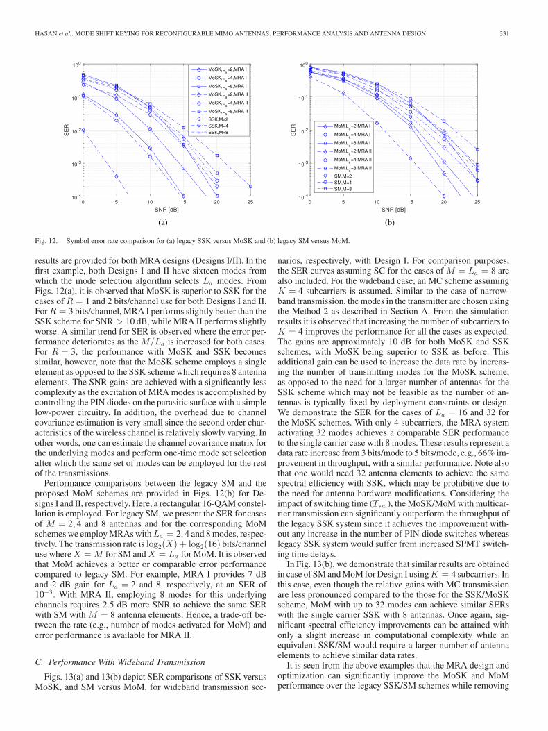
Fig. 12. Symbol error rate comparison for (a) legacy SSK versus MoSK and (b) legacy SM versus MoM.
results are provided for both MRA designs (Designs I/II). In thefirst example, both Designs I and II have sixteen modes fromwhich the mode selection algorithm selects La modes. FromFigs. 12(a), it is observed that MoSK is superior to SSK for thecases of R = 1 and 2 bits/channel use for both Designs I and II.For R = 3 bits/channel, MRA I performs slightly better than theSSK scheme for SNR > 10 dB, while MRA II performs slightlyworse. A similar trend for SER is observed where the error per-formance deteriorates as the M/La is increased for both cases.For R = 3, the performance with MoSK and SSK becomessimilar, however, note that the MoSK scheme employs a singleelement as opposed to the SSK scheme which requires 8 antennaelements. The SNR gains are achieved with a significantly lesscomplexity as the excitation of MRA modes is accomplished bycontrolling the PIN diodes on the parasitic surface with a simplelow-power circuitry. In addition, the overhead due to channelcovariance estimation is very small since the second order char-acteristics of the wireless channel is relatively slowly varying. Inother words, one can estimate the channel covariance matrix forthe underlying modes and perform one-time mode set selectionafter which the same set of modes can be employed for the restof the transmissions.
Performance comparisons between the legacy SM and theproposed MoM schemes are provided in Figs. 12(b) for De-signs I and II, respectively. Here, a rectangular 16-QAM constel-lation is employed. For legacy SM, we present the SER for casesof M = 2, 4 and 8 antennas and for the corresponding MoMschemes we employ MRAs with La = 2, 4 and 8 modes, respec-tively. The transmission rate is log2(X) + log2(16) bits/channeluse where X = M for SM and X = La for MoM. It is observedthat MoM achieves a better or comparable error performancecompared to legacy SM. For example, MRA I provides 7 dBand 2 dB gain for La = 2 and 8, respectively, at an SER of10−3. With MRA II, employing 8 modes for this underlyingchannels requires 2.5 dB more SNR to achieve the same SERwith SM with M = 8 antenna elements. Hence, a trade-off be-tween the rate (e.g., number of modes activated for MoM) anderror performance is available for MRA II.
C. Performance With Wideband Transmission
Figs. 13(a) and 13(b) depict SER comparisons of SSK versusMoSK, and SM versus MoM, for wideband transmission sce-
narios, respectively, with Design I. For comparison purposes,the SER curves assuming SC for the cases of M = La = 8 arealso included. For the wideband case, an MC scheme assumingK = 4 subcarriers is assumed. Similar to the case of narrow-band transmission, the modes in the transmitter are chosen usingthe Method 2 as described in Section A. From the simulationresults it is observed that increasing the number of subcarriers toK = 4 improves the performance for all the cases as expected.The gains are approximately 10 dB for both MoSK and SSKschemes, with MoSK being superior to SSK as before. Thisadditional gain can be used to increase the data rate by increas-ing the number of transmitting modes for the MoSK scheme,as opposed to the need for a larger number of antennas for theSSK scheme which may not be feasible as the number of an-tennas is typically fixed by deployment constraints or design.We demonstrate the SER for the cases of La = 16 and 32 forthe MoSK schemes. With only 4 subcarriers, the MRA systemactivating 32 modes achieves a comparable SER performanceto the single carrier case with 8 modes. These results represent adata rate increase from 3 bits/mode to 5 bits/mode, e.g., 66% im-provement in throughput, with a similar performance. Note alsothat one would need 32 antenna elements to achieve the samespectral efficiency with SSK, which may be prohibitive due tothe need for antenna hardware modifications. Considering theimpact of switching time (Tsw ), the MoSK/MoM with multicar-rier transmission can significantly outperform the throughput ofthe legacy SSK system since it achieves the improvement with-out any increase in the number of PIN diode switches whereaslegacy SSK system would suffer from increased SPMT switch-ing time delays.
In Fig. 13(b), we demonstrate that similar results are obtainedin case of SM and MoM for Design I using K = 4 subcarriers. Inthis case, even though the relative gains with MC transmissionare less pronounced compared to the those for the SSK/MoSKscheme, MoM with up to 32 modes can achieve similar SERswith the single carrier SSK with 8 antennas. Once again, sig-nificant spectral efficiency improvements can be attained withonly a slight increase in computational complexity while anequivalent SSK/SM would require a larger number of antennaelements to achieve similar data rates.
It is seen from the above examples that the MRA design andoptimization can significantly improve the MoSK and MoMperformance over the legacy SSK/SM schemes while removing

332 IEEE TRANSACTIONS ON VEHICULAR TECHNOLOGY, VOL. 68, NO. 1, JANUARY 2019
Fig. 13. (a) Legacy SSK versus MoSK with 4 subcarrier. (b) SM and MoM performance, for 4 subcarriers, 16-QAM.
the need for antenna switching circuitry in the RF path andintroducing a smaller number of PIN diode switches in theparasitic layer of the MRAs. The ohmic losses of the PIN diodesused are 0.1 dB. Therefore, if the number of diodes used is notexcessively large, which is one of the optimization criteria indesigning the MRAs, the diode losses do not play any significantrole on the system performance.
VII. CONCLUDING REMARKS
In this paper, we have proposed employing MRAs with dy-namically changeable modes for SSK/SM based transmission,which are referred to as mode-shift keying (MoSK) and modemodulation (MoM) schemes, and demonstrated that the pro-posed schemes can accommodate higher data rates and offer im-proved error probabilities compared to legacy SSK and SM. Wedeveloped two MRA designs that are optimized for MoSK/MoMbased transmissions. By utilizing the radiation pattern sets, i.e.,modes, resulting in low correlations among the spatial channels,which is not possible with the usual SSK/SM, decoding errorscan be reduced. We have shown that the additional flexibilityoffered by the modes of the MRAs can improve the systemperformance with a significant reduction in complexity. More-over, simulation results show that MoSK/MoM with MC basedtransmission can achieve lower symbol error rates for a giventransmit SNR compared to SC based MoSK/MoM. The flexi-bility of MRA elements allows for dynamically changing andoptimizing the number of operational modes and hence createsa very efficient spatial modulation scheme.
In this work, we have focused on the ideal performance forboth SSK/SM and MoSK/MoM schemes. Extension of the anal-ysis to evaluate the impact of the channel estimation errors onthe performance may be pursued as a further study. Alterna-tive MRA architectures that can result in radiation patterns withlower pattern correlations can also be investigated. In addi-tion, a system level design approach where MIMO transmissionschemes and MRAs are jointly designed open up other interest-ing research directions. Finally, we note that these ideas can alsobe useful for general MIMO transmission where the wirelesssystem can switch between different MIMO schemes includingprecoding, spatial multiplexing, space-time coding in additionto the SSK/SM type transmissions.
APPENDIX
PEP BOUND FOR MOSK AND MOM
For the MoSK scheme, assuming that the channel is fixed fora transmitted waveform s normalized to unit power, the PEP andthe resulting Chernoff bound for maximum likelihood decodingof the mode index can be expressed, respectively, as
P (μ → μ|hm (μ),hm (μ)) = Q
(√P‖Δm (μ, μ)‖2
F
2σ2
)
≤ exp(− P
4σ2‖Δm (μ, μ)‖2
F
)
(28)
where Δm (μ, μ) = hm (μ) − hm (μ) and ‖ · ‖F denotes theFrobenius norm. For the jointly Gaussian hm (μ) and hm (μ),the channel vector difference hm (μ) − hm (μ) becomes a zero-mean complex Gaussian vector with covariance matrix
Υμ/μ = Υμ,μ + Υμ ,μ − Υμ,μ − Υμ ,μ . (29)
By proper design of the underlying antenna modes (μ, μ), andassuming rich scattering, this covariance matrix can be madefull-rank, i.e., rank(Υμ/μ) = N. Using the characteristic func-tion of ‖x − y‖2
F derived in [27], the PEP averaged over thefading channel for the MoSK can then be obtained as
P (μ → μ) ≤ Ehm (μ),hm (μ)
{exp
(− P
4σ2‖Δm (μ, μ)‖2
F
)}
(30)
≤∣∣∣∣IN +
P
4σ2Υμ/μ
∣∣∣∣−1
. (31)
We note that this result is similar to that of space-time codingtransmission where the code-word difference matrix appearingin the case of space-time coding is replaced by the covariancematrix of the channel difference [26]. Let Ma ⊆ M denote aset of La ≤ Lμ modes selected from all available modes M.For the high-SNR regime, a union bound on the average error
HASAN et al.: MODE SHIFT KEYING FOR RECONFIGURABLE MIMO ANTENNAS: PERFORMANCE ANALYSIS AND ANTENNA DESIGN 333
probability for mode group Ma can be obtained as
P (Ma) ≤(
P
4σ2
)−N 1La
∑μ �=μ
μ,μ∈Ma
d(μ, μ)−1 (32)
where d(μ, μ) = λ1 · λ2 · · · λN , and λi > 0 are the eigenval-ues of Υμ/μ . Note that a similar union bound can be ob-tained for SSK scheme where d(μ, μ) is replaced by d(m, m) =ω1 · ω2 . . . ωN with ωi > 0 denoting the eigenvalues of Ψm/m
in (9), and La by M .For the MoM, a similar analysis can be performed to find the
PEP bound for the MLD of (μ, s) as (μ, s) as
P (μ → μ, s → s) ≤∣∣∣∣IN +
P
4σ2Φμ/μ
∣∣∣∣−1
(33)
where Φμ/μ = |s|2Υμ,μ + |s|2Υμ ,μ − ss∗Υμ,μ − s∗sΥμ ,μ .
REFERENCES
[1] M. D. Renzo and H. Haas, “Space shift keying (SSK) MIMO over corre-lated Rician fading channels: Performance analysis and a new method fortransmit-diversity,” IEEE Trans. Commun., vol. 59, no. 1, pp. 116–129,Jan. 2011.
[2] J. Jeganathan, A. Ghrayeb, L. Szczecinski, and A. Ceron, “Space shiftkeying modulation for MIMO channels,” IEEE Trans. Wireless Commun.,vol. 8, no. 7, pp. 3692–3703, Jul. 2009.
[3] J. Jeganathan, A. Ghrayeb, and L. Szczecinski, “Generalized space shiftkeying modulation for MIMO channels,” in Proc. IEEE 19th Int. Symp.Pers., Indoor Mobile Radio Commun., Sep. 2008, pp. 1–5.
[4] R. Mesleh, H. Haas, S. Sinanovic, C. W. Ahn, and S. Yun, “Spatial modula-tion,” IEEE Trans. Veh. Technol., vol. 57, no. 4, pp. 2228–2241, Jul. 2008.
[5] M. Di Renzo, H. Haas, A. Ghrayeb, S. Sugiura, and L. Hanzo, “Spatialmodulation for generalized MIMO: Challenges, opportunities, and imple-mentation,” Proc. IEEE, vol. 102, no. 1, pp. 56–103, Jan. 2014.
[6] B. Cetiner, H. Jafarkhani, J.-Y. Qian, H. J. Yoo, A. Grau, and F. DeFlaviis, “Multifunctional reconfigurable MEMS integrated antennas foradaptive MIMO systems,” IEEE Commun. Mag., vol. 42, no. 12, pp. 62–70, Dec. 2004.
[7] A. Sayeed and V. Raghavan, “Maximizing MIMO capacity in sparse mul-tipath with reconfigurable antenna arrays,” IEEE J. Sel. Topics SignalProcess., vol. 1, no. 1, pp. 156–166, Jun. 2007.
[8] D. Piazza, N. Kirsch, A. Forenza, R. Heath, and K. Dandekar, “Design andevaluation of a reconfigurable antenna array for MIMO systems,” IEEETrans. Antennas Propag., vol. 56, no. 3, pp. 869–881, Mar. 2008.
[9] A. Grau, H. Jafarkhani, and F. De Flaviis, “A reconfigurable multiple-inputmultiple-output communication system,” IEEE Trans. Wireless Commun.,vol. 7, no. 5, pp. 1719–1733, May 2008.
[10] B. Cetiner, E. Akay, E. Sengul, and E. Ayanoglu, “A MIMO systemwith multifunctional reconfigurable antennas,” IEEE Antennas WirelessPropag. Lett., vol. 5, no. 1, pp. 463–466, Dec. 2006.
[11] B. Cetiner, D. Rodrigo, and L. Jofre, “Reconfigurable antennas uti-lizing parasitic pixel layers,” WO Patent App. PCT/US2012/059,378,Jul. 18, 2013. [Online]. Available: http://www.google.com/patents/WO2013106106A2?cl=en
[12] Z. Bouida, H. El-Sallabi, A. Ghrayeb, and K. Qaraqe, “Reconfigurableantenna-based space-shift keying (SSK) for MIMO Rician channels,”IEEE Trans. Wireless Commun., vol. 15, no. 1, pp. 446–457, Jan. 2016.
[13] X. Yuan et al., “A parasitic layer-based reconfigurable antenna designby multi-objective optimization,” IEEE Trans. Antennas Propag., vol. 60,no. 6, pp. 2690–2701, Jun. 2012.
[14] A. K. Khandani, “Media-based modulation: A new approach to wirelesstransmission,” in Proc. IEEE Int. Symp. Inf. Theory, Jul. 2013, pp. 3050–3054.
[15] D. Pozar, Microwave Engineering, 4th ed. New York, NY, USA: Wiley,2011.
[16] M. Di Renzo, H. Haas, and P. M. Grant, “Spatial modulation for multiple-antenna wireless systems: A survey,” IEEE Commun. Mag., vol. 49, no. 12,pp. 182–191, Dec. 2011.
[17] M. Di Renzo and H. Haas, “Bit error probability of SM-MIMO overgeneralized fading channels,” IEEE Trans. Veh. Technol., vol. 61, no. 3,pp. 1124–1144, Mar. 2012.
[18] J. Jeganathan, A. Ghrayeb, and L. Szczecinski, “Spatial modulation: Op-timal detection and performance analysis,” IEEE Commun. Lett., vol. 12,no. 8, pp. 545–547, Aug. 2008.
[19] E. Basar, U. Aygolu, E. Panayirci, and H. Poor, “Space-time block codedspatial modulation,” IEEE Trans. Commun., vol. 59, no. 3, pp. 823–832,Mar. 2011.
[20] S. Sugiura and L. Hanzo, “Single-RF spatial modulation requires single-carrier transmission: Frequency-domain turbo equalization for dispersivechannels,” IEEE Trans. Veh. Technol., vol. 64, no. 10, pp. 4870–4875,Oct. 2015.
[21] S. Ganesan, R. Mesleh, H. Ho, C. W. Ahn, and S. Yun, “On the performanceof spatial modulation OFDM,” in Proc. 40th Asilomar Conf. Signals, Syst.Comput., Oct. 2006, pp. 1825–1829.
[22] ANSYS, “ANSYS HFSS, version 16.0,” 2016. [Online]. Available:http://www.ansys.com
[23] A. Kalis, A. Kanatas, and C. Papadias, Parasitic Antenna Ar-rays for Wireless MIMO Systems. New York, NY, USA: Springer,2013.
[24] C. Oestges and B. Clerckx, MIMO Wireless Communications: From Real-World Propagation to Space-Time Code Design. Amsterdam, The Nether-lands: Elsevier, 2010.
[25] I. Bahceci, M. Hasan, T. M. Duman, and B. A. Cetiner, “Efficient channelestimation for reconfigurable mimo antennas: Training techniques andperformance analysis,” IEEE Trans. Wireless Commun., vol. 16, no. 1,pp. 565–580, Jan. 2017.
[26] T. M. Duman and A. Ghrayeb, Coding for MIMO Communication Systems.England: John Wiley and Sons, 2007.
[27] R. Mallik, “On multivariate Rayleigh and exponential distributions,”IEEE Trans. Inf. Theory, vol. 49, no. 6, pp. 1499–1515, Jun.2003.
[28] R. Mesleh, O. Hiari, A. Younis, and S. Alouneh, “Transmitter de-sign and hardware considerations for different space modulation tech-niques,” IEEE Trans. Wireless Commun., vol. 16, no. 11, pp. 7512–7522,Nov. 2017.
[29] E. Soujeri and G. Kaddoum, “The impact of antenna switching time onspatial modulation,” IEEE Wireless Commun. Lett., vol. 5, no. 3, pp. 256–259, Jun. 2016.
[30] Hewlett-Packard, “Fast switching PIN diodes – Application note 929,”Nov. 1999. [Online]. Available: https://www.keysight.com
[31] B. Wang and F. Zhang, “Some inequalities for the eigenvalues of the prod-uct of positive semidefinite Hermitian matrices,” Linear Algebra Appl.,vol. 160, pp. 113–118, 1992.
[32] 3GPP, “TS 38.211: NR – Physical channels and modulation (rel.15),” Sep. 2017. [Online]. Available: http://www.3gpp.org/ftp//Specs/archive/38_series/38.211/38211-100.zip
[33] 3GPP, “TS 38.214: NR – Physical layer procedures for data(rel. 15),” Sep. 2017. [Online]. Available: http://www.3gpp.org/ftp//Specs/archive/38_series/38.214/38214-f00.zip
[34] Z. Li, D. Rodrigo, L. Jofre, and B. Cetiner, “A new class of antenna arraywith a reconfigurable element factor,” IEEE Trans. Antennas Propag.,vol. 61, no. 4, pp. 1947–1955, Apr. 2013.
[35] D. Rodrigo, B. Cetiner, and L. Jofre, “Frequency, radiation patternand polarization reconfigurable antenna using a parasitic pixel layer,”IEEE Trans. Antennas Propag., vol. 62, no. 6, pp. 3422–3427, Jun.2014.
[36] Z. Li, E. Ahmed, A. Eltawil, and B. Cetiner, “A beam-steering reconfig-urable antenna for WLAN applications,” IEEE Trans. Antennas Propag.,vol. 63, no. 1, pp. 24–32, Jan. 2015.
[37] F. Ferrero, C. Luxey, G. Jacquemod, R. Staraj, and V. Fusco, “A reconfig-uralbe hybrid coupler circuit for agile polarisation antenna,” in Proc. 1stEur. Conf. Antennas Propag., Nov. 2006, pp. 1–5.
[38] P. Kysti et al., “IST-4-027756 WINNER II D1.1.2 v.1.1: WIN-NER II channel models,” CELTIC/WINNER Project, Tech. Rep., Sep.2007.
[39] S. Jaeckel, K. Borner, L. Thiele, and V. Jungnickel, “A geomet-ric polarization rotation model for the 3-D spatial channel model,”IEEE Trans. Antennas Propag., vol. 60, no. 12, pp. 5966–5977,Dec. 2012.
[40] K. Maliatsos and A. Kanatas, “Modifications of the IST-WINNER channelmodel for beamspace processing and parasitic arrays,” in Proc. 7th Eur.Conf. Antennas Propag., Apr. 2013, pp. 989–993.

334 IEEE TRANSACTIONS ON VEHICULAR TECHNOLOGY, VOL. 68, NO. 1, JANUARY 2019
Mehedi Hasan received the B.Sc. degree in electricalengineering from the Bangladesh University of En-gineering and Technology, Dhaka, Bangladesh, andthe Ph.D. degree in electrical engineering from UtahState University, Logan, UT, USA, in 2018. From2013 to 2015, he was with Samsung R&D InstituteBangladesh. He is currently a Senior System Engi-neer with Marvell Semiconductor Inc., Santa Clara,CA, USA. His current research interest are in SerDessystems and signal processing for his high speed datacommunications.
Israfil Bahceci (S’01–M’06) received the B.S. de-gree in electrical engineering from Bilkent Univer-sity, Ankara, Turkey, in 1999, the M.S. degree inelectrical engineering from Arizona State University,Tempe, AZ, USA, in 2001, and the Ph.D. degree inelectrical engineering from the Georgia Institute ofTechnology, Atlanta, GA, USA, in 2005. He is cur-rently a 5G RAN Developer with Ericsson CanadaR&D, Kanata, ON, Canada. He was a PostdoctoralFellow with the University of Waterloo, Waterloo,ON, Canada, from 2005 to 2007. He worked as an
R&D Engineer with Nortel Networks, Canada (2007–2009), and Huawei Tech-nologies, Canada (2009–2011), and as an Assistant Professor with the TOBBUniversity of Economics and Technology from 2011 to 2015. From 2015 to2017, he was a Research Scientist with the Department of Electrical and Com-puter Engineering, Utah State University, Logan, UT, USA, and he acted as VicePresident for i5 Technologies, Inc., Logan, UT, USA. His current research inter-ests include systems, with a particular focus on communication and signal pro-cessing, wireless and mobile communications, distributed estimation/detection,and reconfigurable antenna systems for 5G and beyond systems.
Md. Asaduzzaman Towfiq received the B.S. de-gree in electrical and electronics engineering fromthe Bangladesh University of Engineering and Tech-nology, Dhaka, Bangladesh, in 2013, and the Ph.D.degree in electrical engineering from Utah State Uni-versity, Logan, UT, USA, in 2018. He is currentlya Senior Engineer and Vice President with the i5Technologies, Inc., Logan, UT, USA. His researchinterests include reconfigurable antenna, phased ar-ray, and mmWave antennas.
Tolga M. Duman (S’95–M’98–SM’03–F’11) re-ceived the B.S. degree from Bilkent University,Ankara, Turkey, in 1993, and the M.S. and Ph.D.degrees from Northeastern University, Boston, MA,USA, in 1995 and 1998, respectively, all in electricalengineering.
He is currently a Professor of Electrical and Elec-tronics Engineering Department, Bilkent University.Prior to joining Bilkent University in September2012, he was with the School of ECEE at ArizonaState University as an Assistant Professor from 1998
to 2004, an Associate Professor from 2004 to 2008, and a Professor after 2008.His current research interests are in systems, with particular focus on commu-nication and signal processing, including wireless and mobile communications,coding/modulation, coding for wireless communications, data storage systems,and underwater acoustic communications.
Dr. Duman was the recipient of the National Science Foundation CAREERAward and the IEEE Third Millennium Medal. He served as an Editor of theIEEE TRANSACTIONS ON WIRELESS COMMUNICATIONS from 2003 to 2008,IEEE COMMUNICATIONS SURVEYS AND TUTORIALS from 2002 to 2007, IEEETRANSACTIONS ON COMMUNICATIONS from 2007 to 2012, and Physical Commu-nication (Elsevier) from 2010 to 2016. He has been the coding and informationtheory Area Editor of IEEE TRANSACTIONS ON COMMUNICATIONS since 2011,an Editor of IEEE TRANSACTIONS ON WIRELESS COMMUNICATIONS and theEditor-in-Chief of Physical Communication (Elsevier) since 2016.
Bedri A. Cetiner (M’99–SM’18) received the Ph.D.degree in electronics and communications engi-neering from Yildiz Technical University, Istanbul,Turkey, in 1999. He was a North Atlantic Treaty Or-ganization Science Fellow with the University of Cal-ifornia at Los Angeles, Los Angeles, CA, USA from1999 to 2000. From 2000 to 2004, he was a ResearchScientist with the Electrical Engineering and Com-puter Science Department, University of Californiaat Irvine, Irvine, CA, USA. From 2004 to 2007, hewas an Assistant Professor with the Department of
Space Science and Engineering, Morehead State University, Morehead, KY,USA. In 2007, he joined Utah State University, Logan, UT, USA, where he iscurrently a Professor with the Department of Electrical Engineering. He is alsoa Founder, President, and CEO of i5 Technologies Inc., Logan, UT, USA. He isthe Principal Inventor of nine patented technologies in the area of wireless com-munications. His current research interests include the applications of micro-and nanotechnologies to a new class of microwave/millimeter-wave circuits andsystems, and intelligent wireless communications systems with an emphasis onmultifunctional reconfigurable antenna equipped MIMO systems. He is a mem-ber of the IEEE Antennas and Propagation, Microwave Theory and Techniques,and Communication Societies.