modbus protocol - nastec€¦ · modbus is a serial communication. simple and robust, it has become...
TRANSCRIPT

Modbus Protocol for VASCO, VASCO Solar and MIDA devices
manMODBUS_eng_00

2
Index
1. Modbus introduction ......................................................................................................................................................... 3
2. Modbus on Nastec devices ................................................................................................................................................ 3
3. Transmission modes .......................................................................................................................................................... 3
4. Connections ....................................................................................................................................................................... 3
5. Programming ..................................................................................................................................................................... 4
6. Index list ............................................................................................................................................................................ 5
7. Definitions ........................................................................................................................................................................13
8. Function codes .................................................................................................................................................................17

3
1. Modbus introduction Modbus is a serial communication. Simple and robust, it has become a de-facto standard communication protocol, and it is
now a commonly available means of connecting industrial electronic devices.
Modbus enables communication among many devices connected to the same network. Modbus is often used to connect a
supervisory computer with a remote terminal unit (RTU) in supervisory control and data acquisition (SCADA) systems.
The development and update of Modbus protocols is managed by the Modbus Organization, an association of users and
suppliers of Modbus compliant devices that seeks to drive the adoption and evolution of Modbus.
2. Modbus on Nastec devices Modbus communication is performed on Nastec devices using RS485 Modbus serial port (if available).
Modbus communication is based on master-slaves configuration where the central unit (PLC, PC or BMS) acts as a master in
the network and Nastec devices act as slaves. Master is thus able to monitor and program slaves sending or receiving
messages based on Modbus protocol.
3. Transmission modes Transmission mode used with Nastec devices has to be Modbus RTU.
In particular, it is possible to choose between four types of modes:
RTU N81: 1 start bit, 8 data bits, 1 stop bit, No parity
RTU N82: 1 start bit, 8 data bits, 2 stop bits, No parity
RTU E81: 1 start bit, 8 data bits, 1 stop bit, Even parity
RTU O81: 1 start bit, 8 data bits, 1 stop bit, Odd parity
4. Connections
Connections must be performed only by trained, skilled, and qualified personnel.
Before performing any connection, disconnect the device from the main power supply and do not
open it without having waited at least 5 minutes.
After connections are performed, closed the device and tight all screws on the cover with washers
before powering the device. Otherwise, there may be a failure to connect the cover to ground,
creating the risk of electric shock or even death.
Single pump application

4
Multi-pump application (COMBO mode)
5. Programming Access to “menu: connectivity” (default password 002) and set following parameters:
Parameters Default Description
1 MODBUS address from 1 to 247
9600 MODBUS baudrate from 1200 bps to 57600 bps
RTU N81
MODBUS data format: RTU N81, RTU N82, RTU E81, ETU O81
MODBUS address
XXX
MODBUS baudrate
XXXXX
MODBUS data format
XXXXX

5
6. Index list
Modbus
Index
HEX
Modbus
index
DEC
Function Menù
category Description Range (DECIMAL) Notes
33 51 03,06
Start / Stop
of the
inverter
0=OFF 1=ON
34 52 03,06 Control Set Value [0 - 999,9] (unit) 0 - 9999 (in 1/10 steps)
Sensor range
definition
dependent
35 53 03,06 Control Delta start [0 - 999,9] (unit) 0 - 9999 (in 1/10 steps)
Sensor range
definition
dependent
36 54 03,06 IN / OUT Full scale
sensor [0,1 - 999,9] (unit) 1 - 9999 (in 1/10 steps)
37 55 03,06 Motor
Rated
motor
frequency
[0 - 500] Hz
38 56 03,06 Control Operating
frequency [F_min_motor - F_max_motor] Hz
Frequency range
definition
dependent
39 57 03,06 Motor
Rated
motor
voltage
[50 - 460] V Inverter model
dependent
3A 58 03,06 Motor Voltage
boost [0 - 5,0] % 0 - 50 (in 1/10 steps)
3B 59 03,06 Motor Ramp up
time
[1,0 - 300,0] sec 10 - 3000 (in 1/10
steps)
3C 60 03,06 Motor Ramp down
time
[1,0 - 300,0] sec 10 - 3000 (in 1/10
steps)
3D 61 03,06 Motor PWM
1=2,5KHz 2=4KHz 3=6KHz
4=8KHz 5=10KHz
3E 62 03,06 Motor Ramp f min
motor [1,0 - 30,0] sec 10 - 300 (in 1/10 steps)
3F 63 03,06 Control Set Value 2 [0 - 999,9] (unit) 0 - 9999 (in 1/10 steps)
Sensor range
definition
dependent
40 64 03,06 Control Kp [1 - 9999]
41 65 03,06 Control Ki [0 - 20000]

6
Modbus
Index
HEX
Modbus
index
DEC
Function Menù
category Description Range (DECIMAL) Notes
42 66 03,06 Control Min alarm
value [0 - 999,9] (unit) 0 - 9999 (in 1/10 steps)
Sensor range
definition
dependent
43 67 03,06 Motor
Rated
motor
current
[1,0 - 93,5] A 10 - 935 (in 1/10 steps) Inverter model
dependent
44 68 03,06 Control Control
mode
0=Fix speed 1=Constant value
2=MPPT 3=Fix speed 2 values
5=External speed 7=Constant value 2
set
Inverter model
dependent
45 69 03,06 IN / OUT Offset input
1 [0 - 99,9] % 0 - 999 (in 1/10 steps)
46 70 03,06 Control Dry run
cosphy [0 - 1,00] 0 - 100 (in 1/100 steps)
47 71 03,06 Control Frequency
min control [F_min_motor - F_max_motor] Hz
Frequency range
definition
dependent
48 72 03,06 Motor Min motor
frequency [10 - F_max_motor] Hz
Frequency range
definition
dependent
49 73 03,06 Boolean
word 2 Boolean words definition reference See definitions
4A 74 03,06 Motor Max motor
frequency [10 - F_rated_motor] Hz
Frequency range
definition
dependent
4B 75 03,06 Control Operating
frequency 2 [F_min_motor - F_max_motor] Hz
Frequency range
definition
dependent
4C 76 03,06 Boolean
word 1 Boolean words definition reference See definitions
4D 77 03,06 Control Start delay
AUX [0 - 99] sec
4E 78 03,06 Control Delta stop [0 - 999,9] (unit) 0 - 9999 (in 1/10 steps)
Sensor range
definition
dependent
4F 79 03,06 Control Value set
update [1 - 99] sec
50 80 03,06 Control Stop delay [1 - 99] sec

7
Modbus
Index
HEX
Modbus
index
DEC
Function Menù
category Description Range (DECIMAL) Notes
51 81 03,06 Control Max alarm
value [0 - 999,9] (unit) 0 - 9999 (in 1/10 steps)
Sensor range
definition
dependent
52 82 03,06 Control Address
(COMBO) [0 - 7]
53 83 03,06 IN / OUT
Digital
Input
1,2,3,4
Digital inputs definition reference See definitions
54 84 03,06 IN / OUT
Digital
Input 2/3
delay
[1 - 99] sec
55 85 03,06 IN / OUT Offset input
2 [0 - 99,9] % 0 - 999 (in 1/10 steps)
56 86 03,06 IN / OUT Offset input
3 [0 - 99,9] % 0 - 999 (in 1/10 steps)
57 87 03,06 IN / OUT Offset input
4 [0 - 99,9] % 0 - 999 (in 1/10 steps)
58 88 03,06 IN / OUT Unit
0=bar 1=psi 2=atm 3=m3/h
4=l/min 5=gpm 6=°C 7=°F 8=°K
9=m 10=cm 11=in 12=ft 13=%
59 89 03,06 IN / OUT Min value
sensor [0 - 999,9] (unit) 0 - 9999 (in 1/10 steps)
5A 90 03,06 Control Control
ramp
[1,0 - 300,0] sec 10 - 3000 (in 1/10
steps)
5B 91 03,06 Motor V / f linear -
> quadratic [0 - 100] %
5C 92 03,06 Control Delta
control [0 - 999,9] (unit) 0 - 9999 (in 1/10 steps)
Sensor range
definition
dependent
5D 93 03,06 Control Restart
delay [1 - 99] min
5E 94 03,06 Control Periodic
autorun [0 - 99] h
5F 95 03,06 IN / OUT AN1, AN2
function
0=Indipendent 1=Selectable
2=Difference 1-2 3=Higher value
4=Lower value
60 96 03,06 Control Compens. [0 - 999,9] (unit) 0 - 9999 (in 1/10 steps)
Sensor range
definition
dependent
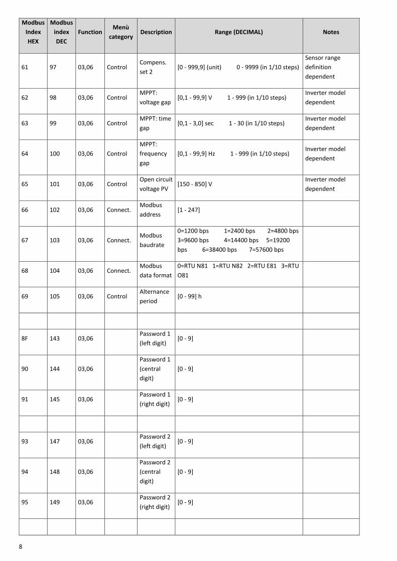
8
Modbus
Index
HEX
Modbus
index
DEC
Function Menù
category Description Range (DECIMAL) Notes
61 97 03,06 Control Compens.
set 2 [0 - 999,9] (unit) 0 - 9999 (in 1/10 steps)
Sensor range
definition
dependent
62 98 03,06 Control MPPT:
voltage gap [0,1 - 99,9] V 1 - 999 (in 1/10 steps)
Inverter model
dependent
63 99 03,06 Control MPPT: time
gap [0,1 - 3,0] sec 1 - 30 (in 1/10 steps)
Inverter model
dependent
64 100 03,06 Control
MPPT:
frequency
gap
[0,1 - 99,9] Hz 1 - 999 (in 1/10 steps) Inverter model
dependent
65 101 03,06 Control Open circuit
voltage PV [150 - 850] V
Inverter model
dependent
66 102 03,06 Connect. Modbus
address [1 - 247]
67 103 03,06 Connect. Modbus
baudrate
0=1200 bps 1=2400 bps 2=4800 bps
3=9600 bps 4=14400 bps 5=19200
bps 6=38400 bps 7=57600 bps
68 104 03,06 Connect. Modbus
data format
0=RTU N81 1=RTU N82 2=RTU E81 3=RTU
O81
69 105 03,06 Control Alternance
period [0 - 99] h
8F 143 03,06 Password 1
(left digit) [0 - 9]
90 144 03,06
Password 1
(central
digit)
[0 - 9]
91 145 03,06 Password 1
(right digit) [0 - 9]
93 147 03,06 Password 2
(left digit) [0 - 9]
94 148 03,06
Password 2
(central
digit)
[0 - 9]
95 149 03,06 Password 2
(right digit) [0 - 9]
9
Modbus
Index
HEX
Modbus
index
DEC
Function Menù
category Description Range (DECIMAL) Notes
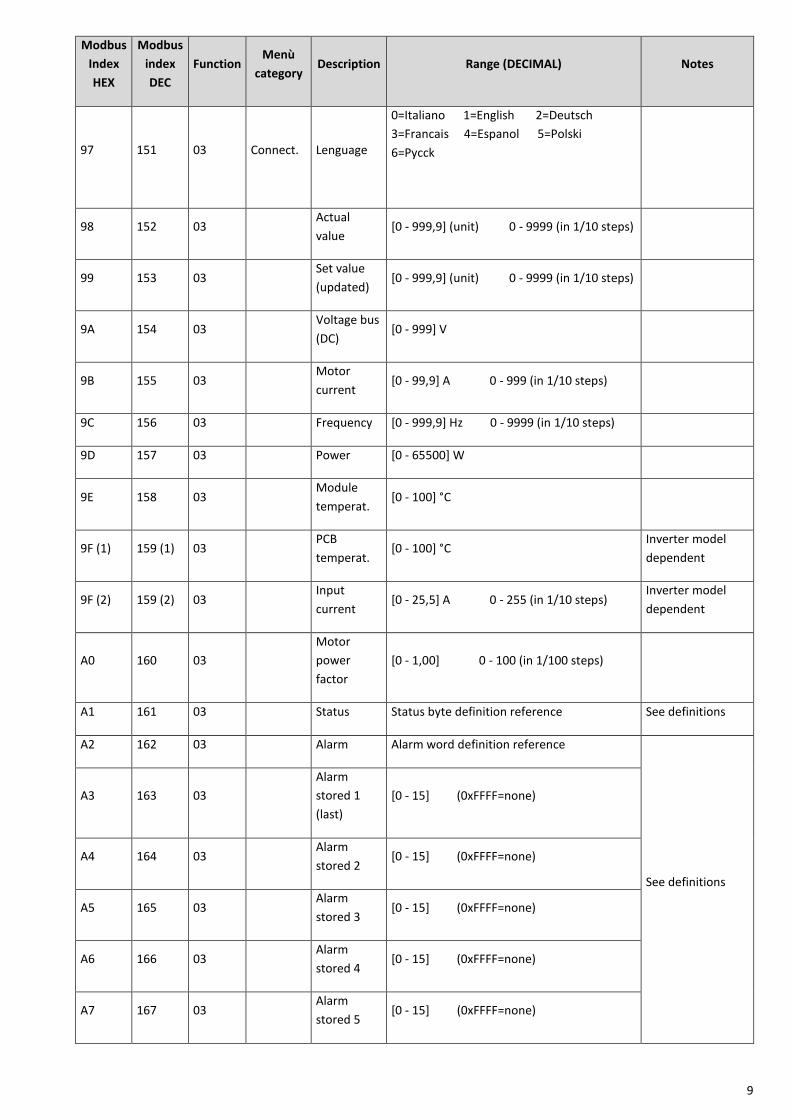
97 151 03 Connect. Lenguage
0=Italiano 1=English 2=Deutsch
3=Francais 4=Espanol 5=Polski
6=Pycck
98 152 03 Actual
value [0 - 999,9] (unit) 0 - 9999 (in 1/10 steps)
99 153 03 Set value
(updated) [0 - 999,9] (unit) 0 - 9999 (in 1/10 steps)
9A 154 03 Voltage bus
(DC) [0 - 999] V
9B 155 03 Motor
current [0 - 99,9] A 0 - 999 (in 1/10 steps)
9C 156 03 Frequency [0 - 999,9] Hz 0 - 9999 (in 1/10 steps)
9D 157 03 Power [0 - 65500] W
9E 158 03 Module
temperat. [0 - 100] °C
9F (1) 159 (1) 03 PCB
temperat. [0 - 100] °C
Inverter model
dependent
9F (2) 159 (2) 03 Input
current [0 - 25,5] A 0 - 255 (in 1/10 steps)
Inverter model
dependent
A0 160 03
Motor
power
factor
[0 - 1,00] 0 - 100 (in 1/100 steps)
A1 161 03 Status Status byte definition reference See definitions
A2 162 03 Alarm Alarm word definition reference
See definitions
A3 163 03
Alarm
stored 1
(last)
[0 - 15] (0xFFFF=none)
A4 164 03 Alarm
stored 2 [0 - 15] (0xFFFF=none)
A5 165 03 Alarm
stored 3 [0 - 15] (0xFFFF=none)
A6 166 03 Alarm
stored 4 [0 - 15] (0xFFFF=none)
A7 167 03 Alarm
stored 5 [0 - 15] (0xFFFF=none)

10
Modbus
Index
HEX
Modbus
index
DEC
Function Menù
category Description Range (DECIMAL) Notes
A8 168 03 Alarm
stored 6 [0 - 15] (0xFFFF=none)
A9 169 03 Alarm
stored 7 [0 - 15] (0xFFFF=none)
AA 170 03 Alarm
stored 8 [0 - 15] (0xFFFF=none)
AB 171 03 Electric life
(high word) [0 - 2^32] sec
AC 172 03 Electric life
(low word)
AD 173 03 Inverter life
(high word) [0 - 2^32] sec
AE 174 03 Inverter life
(low word)
AF 175 03 Motor life
(high word) [0 - 2^32] sec
B0 176 03 Motor life
(low word)
B1 177 03
Frequency
range 1
(high word) [0 - 2^32] sec
See definitions
B2 178 03
Frequency
range 1
(low word)
B3 179 03
Frequency
range 2
(high word) [0 - 2^32] sec
B4 180 03
Frequency
range 2
(low word)
B5 181 03
Frequency
range 3
(high word) [0 - 2^32] sec
B6 182 03
Frequency
range 3
(low word)
B7 183 03
Frequency
range 4
(high word)
[0 - 2^32] sec

11
Modbus
Index
HEX
Modbus
index
DEC
Function Menù
category Description Range (DECIMAL) Notes
B8 184 03
Frequency
range 4
(low word)
BD 189 03
MAC
address
(word 1,
MSW)
2 byte (ASCII characters)
BE 190 03
MAC
address
(word 2)
2 byte (ASCII characters)
BF 191 03
MAC
address
(word 3)
2 byte (ASCII characters)
C0 192 03
MAC
address
(word 4)
2 byte (ASCII characters)
C1 193 03
MAC
address
(word 5)
2 byte (ASCII characters)
C2 194 03
MAC
address
(word 6,
LSW)
2 byte (ASCII characters)
C5 197 03 Address
COMBO [0 - 7] (0x00FF=COMBO OFF)
C6 198 03 SW ctrl/LCD
version
C7 199 03 SW pw/INV
version
C8 200 03 Model code
C9 201 03
Rated
motor
voltage max
Inverter model
dependent
12
Modbus
Index
HEX
Modbus
index
DEC
Function Menù
category Description Range (DECIMAL) Notes
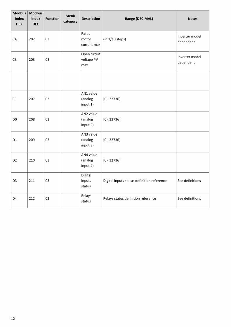
CA 202 03
Rated
motor
current max
(in 1/10 steps) Inverter model
dependent
CB 203 03
Open circuit
voltage PV
max
Inverter model
dependent
CF 207 03
AN1 value
(analog
input 1)
[0 - 32736]
D0 208 03
AN2 value
(analog
input 2)
[0 - 32736]
D1 209 03
AN3 value
(analog
input 3)
[0 - 32736]
D2 210 03
AN4 value
(analog
input 4)
[0 - 32736]
D3 211 03
Digital
inputs
status
Digital inputs status definition reference See definitions
D4 212 03 Relays
status Relays status definition reference See definitions
13
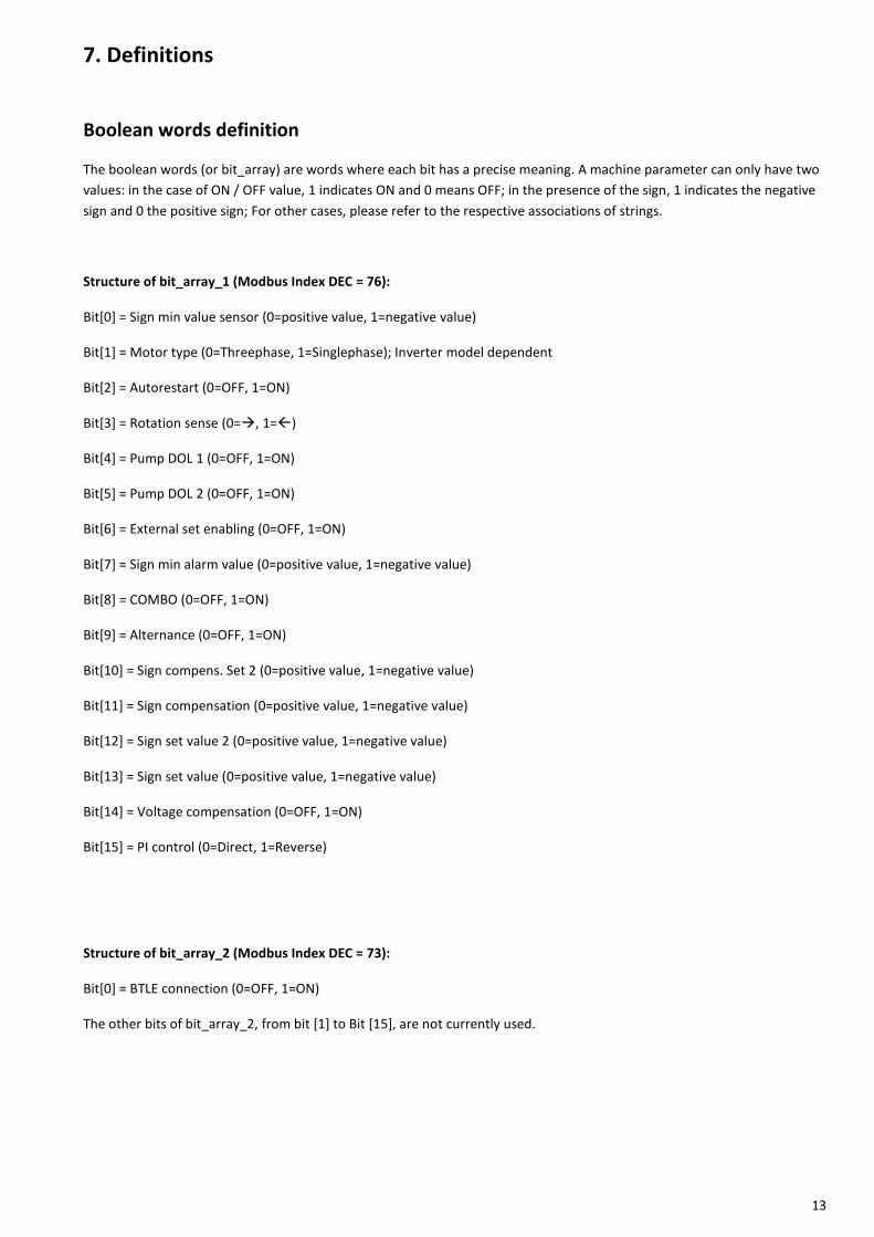
7. Definitions
Boolean words definition
The boolean words (or bit_array) are words where each bit has a precise meaning. A machine parameter can only have two
values: in the case of ON / OFF value, 1 indicates ON and 0 means OFF; in the presence of the sign, 1 indicates the negative
sign and 0 the positive sign; For other cases, please refer to the respective associations of strings.
Structure of bit_array_1 (Modbus Index DEC = 76):
Bit[0] = Sign min value sensor (0=positive value, 1=negative value)
Bit[1] = Motor type (0=Threephase, 1=Singlephase); Inverter model dependent
Bit[2] = Autorestart (0=OFF, 1=ON)
Bit[3] = Rotation sense (0=, 1=)
Bit[4] = Pump DOL 1 (0=OFF, 1=ON)
Bit[5] = Pump DOL 2 (0=OFF, 1=ON)
Bit[6] = External set enabling (0=OFF, 1=ON)
Bit[7] = Sign min alarm value (0=positive value, 1=negative value)
Bit[8] = COMBO (0=OFF, 1=ON)
Bit[9] = Alternance (0=OFF, 1=ON)
Bit[10] = Sign compens. Set 2 (0=positive value, 1=negative value)
Bit[11] = Sign compensation (0=positive value, 1=negative value)
Bit[12] = Sign set value 2 (0=positive value, 1=negative value)
Bit[13] = Sign set value (0=positive value, 1=negative value)
Bit[14] = Voltage compensation (0=OFF, 1=ON)
Bit[15] = PI control (0=Direct, 1=Reverse)
Structure of bit_array_2 (Modbus Index DEC = 73):
Bit[0] = BTLE connection (0=OFF, 1=ON)
The other bits of bit_array_2, from bit [1] to Bit [15], are not currently used.

14
Digital inputs definition
The digital inputs are configured as "Normally closed" or "Normally open" through the individual bits that make up the word
associated with the corresponding parameter.
Structure of parameters Digital input 1,2,3,4 (Modbus Index DEC = 83):
For VASCO devices:
Bit[0] = Digital input IN1 (0=Normally closed, 1=Normally open)
Bit[1] = Digital input IN2 (0=Normally closed, 1=Normally open)
Bit[2] = Digital input IN3 (0=Normally closed, 1=Normally open); Inverter model dependent
Bit[3] = Digital input IN4 (0=Normally closed, 1=Normally open); Inverter model dependent
For MIDA devices:
Bit[2] = Digital IN1 manual reset (0=Enable, 1=Disable); Inverter model dependent
Bit[3] = Digital IN2 manual reset (0=Enable, 1=Disable); Inverter model dependent
The other parameter bits, from Bit[4] to Bit[15], are not currently used.
Status byte definition
This byte allows to know in real time the machine operating status and at the same time lets you know immediately if you
are running as "Stand-alone" or if he works in a COMBO group (the top byte of the word is currently not used).
Association states (Modbus Index DEC = 161):
Parameter Related strings
Status (lower nibble) 0: Inverter OFF, Motor OFF, No alarm (Status normal)
1: Inverter OFF, Motor OFF, Alarm active
2: Inverter ON, Motor OFF, Stand-by
3: Inverter ON, Motor OFF, No water
4: Inverter ON, Motor OFF, Digital input active
5: Inverter OFF, Motor ON, Ramp down (Stop command)
6: Inverter ON, Motor ON, Run
7: Inverter OFF, Motor ON, Ramp down (Alarm active)
8: Inverter ON, Motor ON, Ramp down (Stand-by)
9: Inverter ON, Motor ON, Ramp down (No water)
10: Inverter ON, Motor ON, Ramp down (Digital input active)
Status (higher nibble) <127: Inverter stand-alone (no address)
>127: Inverter COMBO (valid address)

15
Alarm word definition
The alarm is a word where each bit indicates in real time the presence of a particular alarm, suitably associated to this bit.
Association alarm strings (Modbus Index DEC = 162):
Parameter Related strings Associated value for identification in the alarms history
Alarm bit0: Overcurrent motor
bit1: Sensor fault
bit2: Over temperature inverter
bit3: Dry run cosphy
bit4: Under voltage
bit5: Over voltage
bit6: Max value alarm
bit7: Locked rotor
bit8: Overload inverter
bit9: IGBT trip alarm
bit10: No load
bit11: Address error
bit12: No communication
bit13: Min value alarm
bit14: Keyboard fault
bit15: CPU alarm
0
1
2
3
4
5
6
7
8
9
10
11
12
13
14
15
Frequency range 1,2,3,4
The frequency intervals are four symmetrical intervals comprised between the maximum and the minimum motor frequency
set in the advanced parameters.
Example:
Max motor frequency = 50 Hz e Min motor frequency = 30 Hz
Frequency range = (Max motor frequency - Min motor frequency) / 4 = (50 – 30) / 4 = 5 Hz
Thus:
Range (1): da 30 Hz a 35 Hz
Range (2): da 35 Hz a 40 Hz
Range (3): da 40 Hz a 45 Hz
Range (4): da 45 Hz a 50 Hz

16
Digital inputs status definition
The "digital inputs status" is a word that allows to know in real time the logic state of the digital inputs of the machine,
regardless of their configuration N.C. or N.O.
Structure of Digital input status (Modbus Index DEC = 211):
Bit[0] = Digital input IN1 (0=Closed contact, 1=Open contact)
Bit[1] = Digital input IN2 (0=Closed contact, 1=Open contact)
Bit[2] = Digital input IN3 (0=Closed contact, 1=Open contact); Inverter model dependent
Bit[3] = Digital input IN4 (0=Closed contact, 1=Open contact); Inverter model dependent
The other bits of the word, from bit [4] to Bit [15], are red as 0.
Relays status definition
The relays status is a word that allows to know in real time the logic state of the digital outputs (relays).
Structure of Relays status (Modbus Index DEC = 212):
Bit[0] = Relay 1 “STATUS” (0=Disabled, 1=Active)
Bit[1] = Relay 2 “ALARM” (0=Disabled, 1=Active)
Bit[2] = Relay 3 “DOL_1” (0=Disabled, 1=Active); Inverter model dependent
Bit[3] = Relay 4 “DOL_2” (0=Disabled, 1=Active); Inverter model dependent
The other bits of the word, from bit [4] to Bit [15], are red as 0.
17
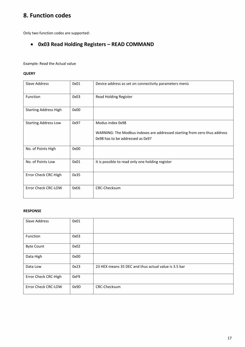
8. Function codes
Only two function codes are supported:
0x03 Read Holding Registers – READ COMMAND
Example: Read the Actual value
QUERY
Slave Address 0x01 Device address as set on connectivity parameters menù
Function 0x03 Read Holding Register
Starting Address High 0x00
Starting Address Low 0x97 Modus index 0x98
WARNING: The Modbus indexes are addressed starting from zero thus address
0x98 has to be addressed as 0x97
No. of Points High 0x00
No. of Points Low 0x01 It is possible to read only one holding register
Error Check CRC-High 0x35
Error Check CRC-LOW 0xE6 CRC-Checksum
RESPONSE
Slave Address 0x01
Function 0x03
Byte Count 0x02
Data High 0x00
Data Low 0x23 23 HEX means 35 DEC and thus actual value is 3.5 bar
Error Check CRC-High 0xF9
Error Check CRC-LOW 0x9D CRC-Checksum

18
0x06 Write Single Register – WRITE COMMAND
Example: Set the “set value” to 4.5 bar
QUERY
Slave Address 0x01 Device address as set on connectivity parameters menù.
Function 0x06 Write Single Register
Register Address High 0x00
Register Address Low 0x33 Modus index 0x34
WARNING: The Modbus indexes are addressed starting from zero thus address
0x34 has to be addressed as 0x33
Preset Data High 0x00
Preset Data Low 0x2D 2D HEX means 45 DEC and thus set the “set value” to 4.5 bar
Error Check CRC-High 0xB9
Error Check CRC-LOW 0xD8 CRC-Checksum
RESPONSE
Slave Address 0x01
Function 0x06
Register Address High 0x00
Register Address Low 0x33
Preset Data High 0x00
Preset Data Low 0x2D 2D HEX means 45 DEC and thus the “set value” is 4.5 bar
Error Check CRC-High 0xB9
Error Check CRC-LOW 0xD8 CRC-Checksum

19
NOTES
Copyright NASTEC srl Nastec reserves the right to modify informations in this manual without any notice. Nastec srl, Via della Tecnica, 8, 36024, Mossano, Vicenza, Italy, Tel. +39 0444 886289, Fax +39 0444 776099, www.nastec.eu, [email protected]