modal analysis of laminated composite plates...
TRANSCRIPT
Modal Analysis of Laminated Composite Plates Using Third Order Shear Deformation Theory
Rastgaar Aagaah M., Mahinfalah M.*, Mahmoudian N., Nakhaie Jazar G. Department of Mechanical Engineering and Applied Mechanics
North Dakota State University, Fargo, ND, 58105, USA *Corresponding author:
Tel: 701-231-8303 Fax: 701-231-8839 Email: [email protected]
ABSTRACT:
In this paper, natural frequencies of square laminated composite plates for different supports at edges are presented. Using a third order shear deformation theory of plates (TSDT), which is categorized in equivalent single layer theories, a new set of linear equations of motion for square multi-layered composite plates has been derived. Laminated plates are supposed to be either angle ply or cross ply. Moreover, FEM is used to solve the equations and find the fundamental natural frequencies. Finally some results for plates with different combination of layers and supports are reported.
KEY WORDS:
Natural frequency, third order shear deformation, laminated composite plate, TSDT, finite element method.
1- INTRODUCTION
Laminated composite plates are widely used in industry and other new fields of technology. Due to high degrees of anisotropy and low rigidity in transverse shear, Kirchhoff hypothesis as a classical theory is no longer adequate. The hypothesis states that transverse normal to the mid plane of a plate remains straight and normal after deformation because of the negligible transverse shear effects. Refined theories based on removing those restrictions of transverse normal have been recently used. As a result, the free vibration frequencies calculated by using the classical thin plate theory are higher than those obtained by Mindlin plate theory in which transverse shear and rotary inertia effects are included [1].
Most of the structural theories used up to now, characterize the behavior of composite laminates fall into the category of equivalent single layer (ESL) theories. Different techniques for analysis of free vibration of composite laminated plates have been done. Reddy and Khedeir [2] presented analytical and finite element solutions for vibration and buckling of laminated composite plates using various plate theories to prove necessity of shear deformation theories to predict the behavior of composite laminates. Khedeir and Reddy [3] obtained a complete set of linear equations of the second order theory to analyze the free vibration behavior of cross-ply and antisymmetric angle-ply laminated plates. In these theories, the material properties of the constituent layers are combined to form a hypothetical single layer whose properties are equivalent to through-the-thickness integrated sum of its constituents. This category of theories has been found to be adequate in predicting global response characteristics of laminates like maximum deflections, maximum stresses, fundamental frequencies, or critical buckling loads [4].
Third order shear deformation theory, which is one of the equivalent single layer theories, is derived. This theory is based on the same assumptions as the classical (CLPT) and first order shear deformation plate theories (FSDT), except that the assumption on the straightness and normality of the transverse normal is relaxed [4, 5, 6]. Theories higher than third order are not used because the accuracy gained is so little that the effort required to solve the equations is not justified [7]. In single-layer displacement-based theories, one single expansion for each displacement component is used through the entire thickness, and therefore, the transverse strains are continuous through the thickness, a strain state appropriate for homogeneous plates [7, 8, 9].
In the present work, Using shear deformation theory and a 7-parameter displacement field, a new set of equations of motion has been derived. Unlike the first order shear deformation theory, the higher order theory does not require shear correction factors. Equations of motion have been solved using finite elements method for a rectangular laminated composite plate. Different numbers of layers and different combinations for layers have been arranged. Both angle ply and cross ply laminates have been considered in this paper. Boundary conditions for plates are such that two of the edges, which are opposite, are always simply supported and the other two edges are used in different combinations of simply supported, free and clamped to be compared with the other reported studies. Comparisons between natural frequencies for different a/h as well as a variety of boundary conditions for several layers have been presented.
SEM X International Congress and Exposition on Experimental and Applied Mechanics, Costa Mesa, CA, June 7 – 10, 2004
2- EQUATION OF MOTION AND MATHEMATICAL TREATMENTS
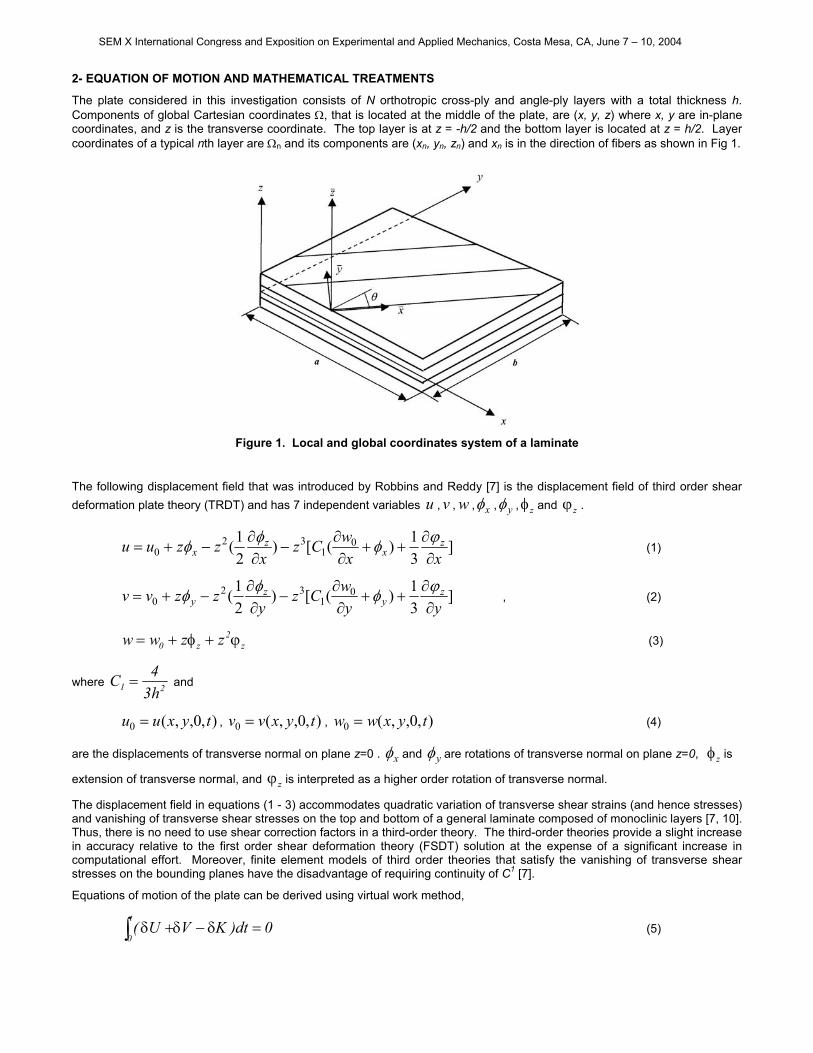
The plate considered in this investigation consists of N orthotropic cross-ply and angle-ply layers with a total thickness h. Components of global Cartesian coordinates Ω, that is located at the middle of the plate, are (x, y, z) where x, y are in-plane coordinates, and z is the transverse coordinate. The top layer is at z = -h/2 and the bottom layer is located at z = h/2. Layer coordinates of a typical nth layer are Ωn and its components are (xn, yn, zn) and xn is in the direction of fibers as shown in Fig 1.
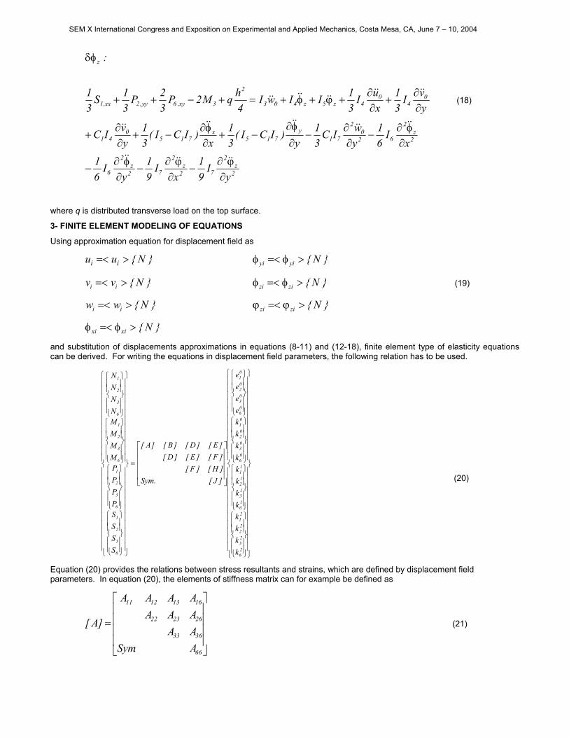
Figure 1. Local and global coordinates system of a laminate
The following displacement field that was introduced by Robbins and Reddy [7] is the displacement field of third order shear deformation plate theory (TRDT) and has 7 independent variables , v , ,u w xφ , yφ , zφ and zϕ .
]31)([)
21( 0
132
0 xxwCz
xzzuu z
xz
x ∂∂
++∂∂
−∂∂
−+=ϕφφφ (1)
]31)([)
21( 0
132
0 yywCz
yzzvv z
yz
y ∂∂
++∂∂
−∂∂
−+=ϕφφφ , (2)
z2
z0 zzww ϕ+φ+= (3)
where 21 h34C = and
),0,,(0 tyxuu = , v , w),0,,(0 tyxv= ),0,,(0 tyxw= (4)
are the displacements of transverse normal on plane z=0 . xφ and yφ are rotations of transverse normal on plane z=0, zφ is
extension of transverse normal, and is interpreted as a higher order rotation of transverse normal. zϕ
The displacement field in equations (1 - 3) accommodates quadratic variation of transverse shear strains (and hence stresses) and vanishing of transverse shear stresses on the top and bottom of a general laminate composed of monoclinic layers [7, 10]. Thus, there is no need to use shear correction factors in a third-order theory. The third-order theories provide a slight increase in accuracy relative to the first order shear deformation theory (FSDT) solution at the expense of a significant increase in computational effort. Moreover, finite element models of third order theories that satisfy the vanishing of transverse shear stresses on the bounding planes have the disadvantage of requiring continuity of C1 [7].
Equations of motion of the plate can be derived using virtual work method,
(5) 0dt)KVU(t
0=δ−δ+δ∫
SEM X International Congress and Exposition on Experimental and Applied Mechanics, Costa Mesa, CA, June 7 – 10, 2004
where U, V, and K are virtual strain energy, virtual work done by applied forces and virtual kinetic energy, respectively, and t is time.
According to displacement field equations (1 - 3) the linear strains are
)kzzkk(zee 21
211
01
011 +++=
)kzzkk(zee 22
212
02
022 +++=
)k(zee 03
033 +=
(6) 2314
044 e2)k(zee =+=
1315
055 e2)k(zee =+=
)kkk(zee 26
16
06
066 +++=
In Appendix A, the relationships between strain components (6) and displacement field equations (1 - 3) are presented.
By substitution of stresses, strains and distributed force in equation (10), the final integral equation for plate elasticity would be,
0dt)dA.dz)wwvvuu(dA)wq(
dA.dz)eeeeee((
00
0
2h
2h
6655443322
T
02h
2h 11
=δ+δ+δρ+δ−
δσ+δσ+δσ+δσ+δσ+δσ
∫ ∫∫
∫ ∫ ∫
Ω −Ω
Ω −
&&&&&&&&&&&&
(7)
where the stress-strain relation in global coordinates are presented in Appendices B and C. We define plate inertia I1…7 and stress resultants Ni, Mi, Si, Qi and Pi as follow:
(8) ∑∫=
+=N
n
zz nn
ndzzzzzzzI
1
654327...1
1 ),,,,,,1(ρ
∑∫=
+ σ=N
1n
z
z
3iiii
1n
n
dz)z,z,1()S,M,N( )6,3,2,1i( = (9)
∑∫=
+ σ=N
1n
z
z ii1n
n
dz)Q( ( )5,4i = (10)
(∑∫=
+ σ=N
1n
z
z
2ii
1n
n
dzz)P( )6,5,4,3,2,1i = (11)
where N is the number of layers. The equation of motion of the plate can be written as:
xI31IC
xwIC
xI21IuINN
:u
z4x41
041
z3x201y,6x,1
0
∂ϕ∂
−φ−∂∂
−∂φ∂
−φ+=+
δ
&&&&&&&&&&&&
(12)
yI31IC
ywIC
yI21IvINN
:v
z4y41
041
z3y201x,6y,2
0
∂ϕ∂
−φ−∂∂
−∂φ∂
−φ+=+
δ
&&&&&&&&&&&&
(13)
SEM X International Congress and Exposition on Experimental and Applied Mechanics, Costa Mesa, CA, June 7 – 10, 2004
2z
2
72z
2
7y
721
x7
212
02
7212
02
7212
z2
612z
2
61
y51
x51
041
041zz201
xy,61x,51y,41y,5y,4yy,21xx,11
0
yI31
xI31
yIC
xIC
ywIC
xwIC
yIC
21
xIC
21
yIC
xIC
yvIC
xuIC
31IwI
qSC2PC3PC3QQSCSC
:w
∂ϕ∂
−∂ϕ∂
−∂φ∂
−
∂φ∂
−∂∂
−∂∂
−∂φ∂
−∂φ∂
−
∂φ∂
+∂φ∂
+∂∂
+∂∂
+ϕ+φ+
=++−−+++
δ
&&&&&&
&&&&&&&&&&
&&&&&&&&&&&&&&
(14)
x)ICI(
31
xw)ICIC(
x)ICI(
21)ICIC2I(u)ICI(
SCMPC3QQSCM
:
z715
07
2151
z412x7
215130412
y,61y,651y,55x,11x,1
x
∂ϕ∂
+−+
∂∂
+−+∂φ∂
−+φ+−+−
=−+++−−
δφ
&&
&&&&&&&&
(15)
y)ICI(
31
yw)ICIC(
y)ICI(
21)ICIC2I(v)ICI(
SCMPC3QQSCM
:
z715
07
2151
z614y7
215130412
x,61x,641y,54x,21x,2
y
∂ϕ∂
+−+
∂∂
+−+∂φ∂
+−+φ+−+−
=−+++−−
δφ
&&
&&&&&&&&
(16)
2z
2
72z
2
72z
2
61
2z
2
6120
2
7212
02
721
y7
2151
x7
2151
041
041z3z2013xy,6yy,2xx,1
z
yI31
xI31
yIC
21
xIC
21
ywIC
xwIC
y)ICIC(
x)ICIC(
yvIC
xuICIIwI
2hqNPP
21P
21
:
∂ϕ∂
−∂ϕ∂
−∂φ∂
−
∂φ∂
−∂∂
−∂∂
−∂φ∂
−+∂φ∂
−
+∂∂
+∂∂
+ϕ+φ+=−−++
δφ
&&&&&&
&&&&&&&&&&
&&&&&&&&&& (17)
SEM X International Congress and Exposition on Experimental and Applied Mechanics, Costa Mesa, CA, June 7 – 10, 2004
2z
2
72z
2
72z
2
6
2z
2
620
2
71y
715x
7150
41
04
04z5z403
2
3xy,6yy,2xx,1
z
yI91
xI91
yI
61
xI
61
ywIC
31
y)ICI(
31
x)ICI(
31
yvIC
yvI
31
xuI
31IIwI
4hqM2P
32P
31S
31
:
∂ϕ∂
−∂ϕ∂
−∂φ∂
−
∂φ∂
−∂∂
−∂φ∂
−+∂φ∂
−+∂∂
+
∂∂
+∂∂
+ϕ+φ+=+−++
δφ
&&&&&&
&&&&&&&&&&
&&&&&&&&&& (18)
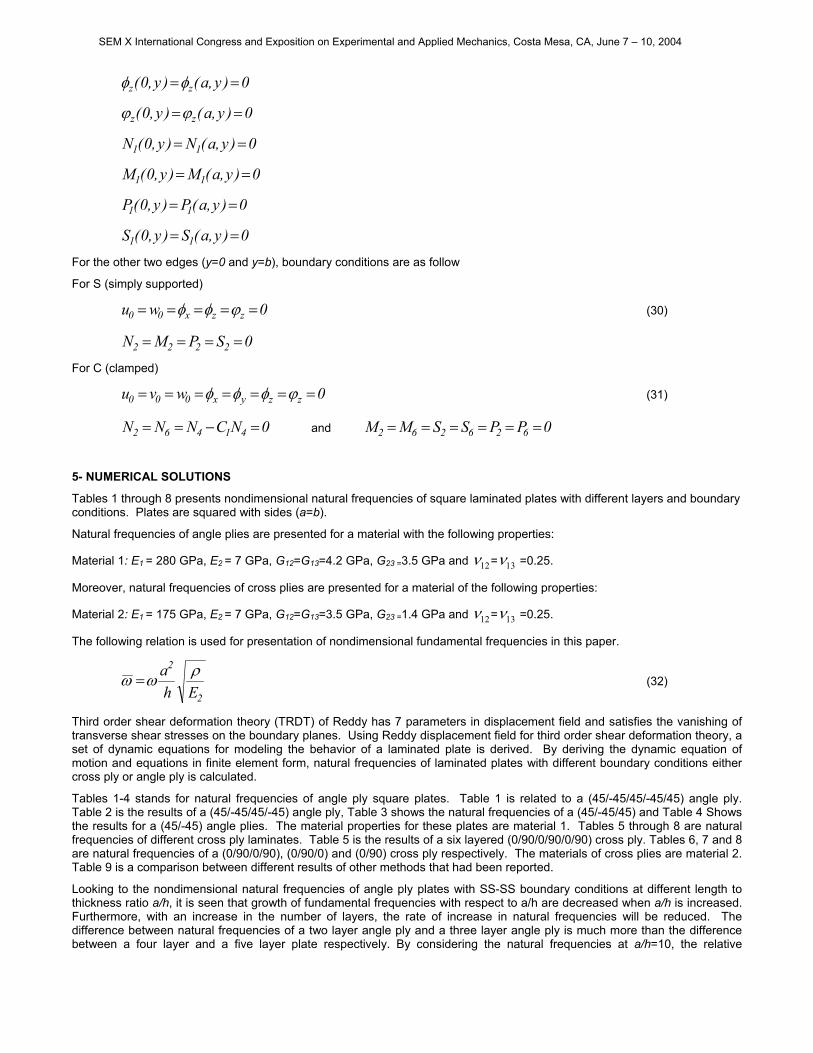
where q is distributed transverse load on the top surface.
3- FINITE ELEMENT MODELING OF EQUATIONS
Using approximation equation for displacement field as
Nuu ii >=< Nyiyi >φ=<φ
Nvv ii >=< Nzizi >φ=<φ (19)
Nww ii >=< Nzizi >ϕ=<ϕ
Nxixi >φ=<φ
and substitution of displacements approximations in equations (8-11) and (12-18), finite element type of elasticity equations t field parameters, the following relation has to be used.
can be derived. For writing the equations in displacemen
(20)
Equation (20) provides the relations between stress resu nts and strains, which are defined by displacement field
(21)
=
26
23
22
21
16
13
12
11
06
03
02
01
06
03
02
01
6
3
2
1
6
3
2
1
6
3
2
1
6
3
2
1
kkkkkkkkkkkkeeee
]J[.Sym]H[]F[]F[]E[]D[]E[]D[]B[]A[
SSSSPPPPMMMMNNNN
ltaparameters. In equation (20), the elements of stiffness matrix can for example be defined as
=
66
3633
262322
16131211
A.SymAAAAAAAAA
]A[
SEM X International Congress and Exposition on Experimental and Applied Mechanics, Costa Mesa, CA, June 7 – 10, 2004

Elements of matrices [A], [B], [D], [E], [F] and [H] are defined as follow.
dz)z,z,z,z,z,z,(Q)J,H,F,E,D,B,A(h
h ijijijijijijijij ∫−= 2
2
654321 )6,3,2,1j,i( = (22)
Stress resultants for in-plane components are defined as
(23)
=
15
14
05
04
5
4
5
4
kkee
]H[]F[]E[]D[]E[]D[]B[]A[
PPQQ
where, for example
=
55
4544
A.SymAA
]A[ (24)
and
dzzzzQEDBAh
h ijijijijij ∫−
= 2
2
32 ),,,1(),,,( )5,4j,i( = (25)
Finally, Using the finite element analysis the equations can be set up in the following form
(26) FX]K[X]M[ =+&&
4- NATURAL FREQUENCIES FOR DIFFERENT BOUNDARY CONDITIONS
Using quadratic 6 nodes triangular elements to satisfy C1-continuty of elements, and imposing the boundary conditions, governing equations can be solved to find fundamental frequencies. It is seen that the governing equations are in general dynamic form. To analyze the static behavior of the plate, the stiffness matrix and the mass vector are needed. ]K[ ]M[
For linear problems the local stiffness matrix [ is independent of element displacement and the following relation is valid for all instants of time
]K X
XX 2ω−=&& (27)
Therefore, the global matrix equations can be written as
0X])M[]K([ m2 =−ω (28)
Natural frequencies of plate can be found from the above relation, where m is equal to 7× number of elements that are used.
We assume that the plate is simply supported at two edges while the boundary conditions at the other two edges, are a combination of boundary conditions are applied. These combinations of supports are SS-SS, SS-SC, SS-CC, SS-FC, SS-FS and SS-FF, where S stands for simply support, C for clamped, and F for free boundary conditions. Primary boundary conditions that are used for displacement based finite element analysis are as follow.
For edges located at x=0 and x=a with simply support condition
0),(),0( 00 == yawyw0),(),0( 00 == yavyv
0),(),0( == yay yy φφ (29)
SEM X International Congress and Exposition on Experimental and Applied Mechanics, Costa Mesa, CA, June 7 – 10, 2004
0)y,a()y,0( zz ==φφ
0)y,a()y,0( zz ==ϕϕ
0)y,a(N)y,0(N 11 ==
0)y,a(M)y,0(M 11 ==
0)y,a(P)y,0(P 11 ==
0)y,a(S)y,0(S 11 ==
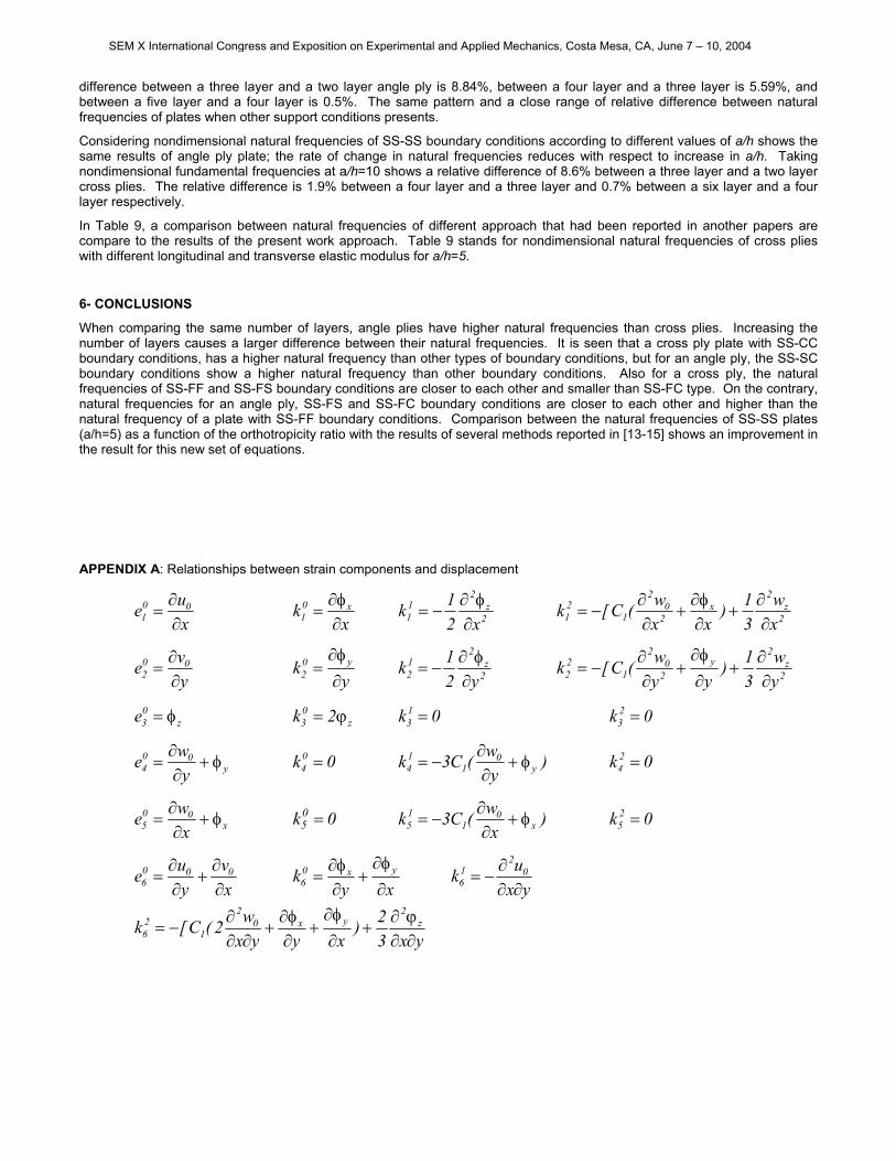
For the other two edges (y=0 and y=b), boundary conditions are as follow
For S (simply supported)
0wu zzx00 ===== ϕφφ (30)
0SPMN 2222 ====
For C (clamped)
0wvu zzyx000 ======= ϕφφφ (31)
and MM0NCNNN 41462 =−== 0PPSS 626262 ======
5- NUMERICAL SOLUTIONS
Tables 1 through 8 presents nondimensional natural frequencies of square laminated plates with different layers and boundary conditions. Plates are squared with sides (a=b).
Natural frequencies of angle plies are presented for a material with the following properties:
Material 1: E1 = 280 GPa, E2 = 7 GPa, G12=G13=4.2 GPa, G23 =3.5 GPa and 12ν = 13ν =0.25.
Moreover, natural frequencies of cross plies are presented for a material of the following properties:
Material 2: E1 = 175 GPa, E2 = 7 GPa, G12=G13=3.5 GPa, G23 =1.4 GPa and 12ν = 13ν =0.25.
The following relation is used for presentation of nondimensional fundamental frequencies in this paper.
2
2
Eha ρωω = (32)
Third order shear deformation theory (TRDT) of Reddy has 7 parameters in displacement field and satisfies the vanishing of transverse shear stresses on the boundary planes. Using Reddy displacement field for third order shear deformation theory, a set of dynamic equations for modeling the behavior of a laminated plate is derived. By deriving the dynamic equation of motion and equations in finite element form, natural frequencies of laminated plates with different boundary conditions either cross ply or angle ply is calculated.
Tables 1-4 stands for natural frequencies of angle ply square plates. Table 1 is related to a (45/-45/45/-45/45) angle ply. Table 2 is the results of a (45/-45/45/-45) angle ply, Table 3 shows the natural frequencies of a (45/-45/45) and Table 4 Shows the results for a (45/-45) angle plies. The material properties for these plates are material 1. Tables 5 through 8 are natural frequencies of different cross ply laminates. Table 5 is the results of a six layered (0/90/0/90/0/90) cross ply. Tables 6, 7 and 8 are natural frequencies of a (0/90/0/90), (0/90/0) and (0/90) cross ply respectively. The materials of cross plies are material 2. Table 9 is a comparison between different results of other methods that had been reported.
Looking to the nondimensional natural frequencies of angle ply plates with SS-SS boundary conditions at different length to thickness ratio a/h, it is seen that growth of fundamental frequencies with respect to a/h are decreased when a/h is increased. Furthermore, with an increase in the number of layers, the rate of increase in natural frequencies will be reduced. The difference between natural frequencies of a two layer angle ply and a three layer angle ply is much more than the difference between a four layer and a five layer plate respectively. By considering the natural frequencies at a/h=10, the relative
SEM X International Congress and Exposition on Experimental and Applied Mechanics, Costa Mesa, CA, June 7 – 10, 2004
difference between a three layer and a two layer angle ply is 8.84%, between a four layer and a three layer is 5.59%, and between a five layer and a four layer is 0.5%. The same pattern and a close range of relative difference between natural frequencies of plates when other support conditions presents.
Considering nondimensional natural frequencies of SS-SS boundary conditions according to different values of a/h shows the same results of angle ply plate; the rate of change in natural frequencies reduces with respect to increase in a/h. Taking nondimensional fundamental frequencies at a/h=10 shows a relative difference of 8.6% between a three layer and a two layer cross plies. The relative difference is 1.9% between a four layer and a three layer and 0.7% between a six layer and a four layer respectively.
In Table 9, a comparison between natural frequencies of different approach that had been reported in another papers are compare to the results of the present work approach. Table 9 stands for nondimensional natural frequencies of cross plies with different longitudinal and transverse elastic modulus for a/h=5.
6- CONCLUSIONS
When comparing the same number of layers, angle plies have higher natural frequencies than cross plies. Increasing the number of layers causes a larger difference between their natural frequencies. It is seen that a cross ply plate with SS-CC boundary conditions, has a higher natural frequency than other types of boundary conditions, but for an angle ply, the SS-SC boundary conditions show a higher natural frequency than other boundary conditions. Also for a cross ply, the natural frequencies of SS-FF and SS-FS boundary conditions are closer to each other and smaller than SS-FC type. On the contrary, natural frequencies for an angle ply, SS-FS and SS-FC boundary conditions are closer to each other and higher than the natural frequency of a plate with SS-FF boundary conditions. Comparison between the natural frequencies of SS-SS plates (a/h=5) as a function of the orthotropicity ratio with the results of several methods reported in [13-15] shows an improvement in the result for this new set of equations.
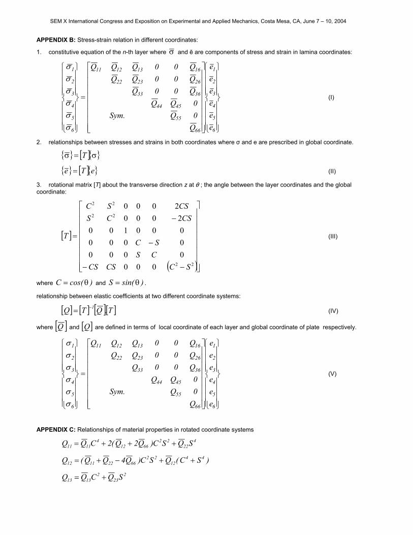
APPENDIX A: Relationships between strain components and displacement
xue 00
1 ∂∂
= x
k x01 ∂
φ∂= 2
z2
11 x2
1k∂φ∂
−= 2z
2x
20
2
121 x
w31)
xxw(C[k
∂∂
+∂φ∂
+∂∂
−=
yve 00
2 ∂∂
= y
k y02 ∂
φ∂= 2
z2
12 y2
1k∂φ∂
−= 2z
2y
20
2
122 y
w31)
yyw(C[k
∂∂
+∂φ∂
+∂∂
−=
z03e φ= k k z
03 2ϕ= 0k13 = 02
3 =
y00
4 ywe φ+∂∂
= 0k04 = )yw(C3k y0
114 φ+
∂∂
−= 0k 24 =
x00
5 xwe φ+∂∂
= 0k05 = )xw(C3k x0
115 φ+
∂∂
−= 0k 25 =
xv
yue 000
6 ∂∂
+∂∂
= xy
k yx06 ∂
φ∂+
∂φ∂
= yxuk 02
16 ∂∂
∂−=
yx3
2)xyyx
w2(C[k z2
yx02
126 ∂∂
ϕ∂+
∂φ∂
+∂φ∂
+∂∂
∂−=
SEM X International Congress and Exposition on Experimental and Applied Mechanics, Costa Mesa, CA, June 7 – 10, 2004
APPENDIX B: Stress-strain relation in different coordinates:
1. constitutive equation of the n-th layer where σ and ē are components of stress and strain in lamina coordinates:
=
6
5
4
3
2
1
66
55
4544
3633
262322
16131211
6
5
4
3
2
1
eeeeee
Q0Q.Sym0QQQ00QQ00QQQ00QQQ
σσσσσσ
(I)
2. relationships between stresses and strains in both coordinates where σ and e are prescribed in global coordinate.
[ ] σ=σ T
[ ] eTe = (II)
3. rotational matrix [T] about the transverse direction z at θ ; the angle between the layer coordinates and the global coordinate:
[ ]
( )
−−
−
−
=
22
22
22
000000000000001002000
2000
SCCSCSCSSC
CSCSCSSC
T (III)
where and . )cos(C θ= )sin(S θ=
relationship between elastic coefficients at two different coordinate systems:
[ ] [ ] [ ][ ]T.QTQ 1−= (IV)
where [Q ] and [ are defined in terms of local coordinate of each layer and global coordinate of plate respectively. ]Q
=
6
5
4
3
2
1
66
55
4544
3633
262322
16131211
6
5
4
3
2
1
eeeeee
Q0Q.Sym0QQQ00QQ00QQQ00QQQ
σσσσσσ
(V)
APPENDIX C: Relationships of material properties in rotated coordinate systems
422
226612
41111 SQSC)Q2Q(2CQQ +++=
)SC(QSC)Q4QQ(Q 4412
2266221112 ++−+=
223
21313 SQCQQ +=
SEM X International Congress and Exposition on Experimental and Applied Mechanics, Costa Mesa, CA, June 7 – 10, 2004
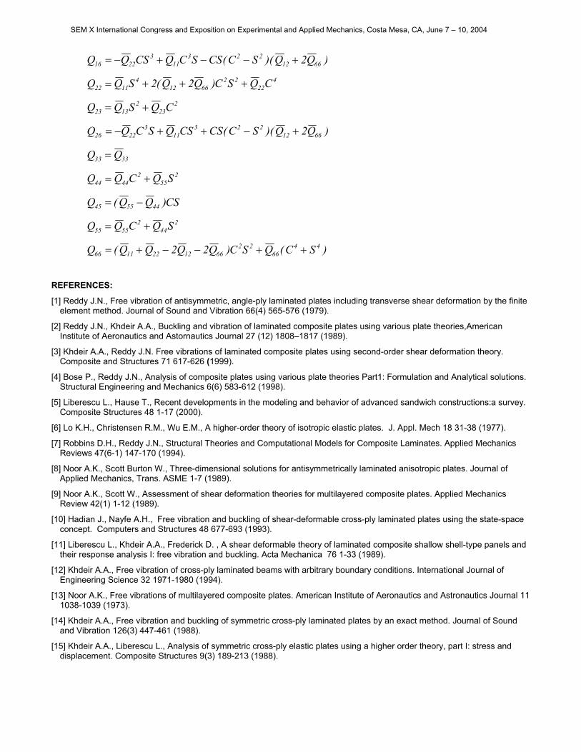
)Q2Q)(SC(CSSCQCSQQ 6612223
113
2216 +−−+−=
422
226612
41122 CQSC)Q2Q(2SQQ +++=
223
21323 CQSQQ +=
)Q2Q)(SC(CSCSQSCQQ 6612223
113
2226 +−++−=
3333 QQ =
255
24444 SQCQQ +=
CS)QQ(Q 445545 −=
244
25555 SQCQQ +=
)SC(QSC)Q2Q2QQ(Q 4466
226612221166 ++−−+=
REFERENCES:
[1] Reddy J.N., Free vibration of antisymmetric, angle-ply laminated plates including transverse shear deformation by the finite element method. Journal of Sound and Vibration 66(4) 565-576 (1979).
[2] Reddy J.N., Khdeir A.A., Buckling and vibration of laminated composite plates using various plate theories,American Institute of Aeronautics and Astornautics Journal 27 (12) 1808–1817 (1989).
[3] Khdeir A.A., Reddy J.N. Free vibrations of laminated composite plates using second-order shear deformation theory. Composite and Structures 71 617-626 (1999).
[4] Bose P., Reddy J.N., Analysis of composite plates using various plate theories Part1: Formulation and Analytical solutions. Structural Engineering and Mechanics 6(6) 583-612 (1998).
[5] Liberescu L., Hause T., Recent developments in the modeling and behavior of advanced sandwich constructions:a survey. Composite Structures 48 1-17 (2000).
[6] Lo K.H., Christensen R.M., Wu E.M., A higher-order theory of isotropic elastic plates. J. Appl. Mech 18 31-38 (1977).
[7] Robbins D.H., Reddy J.N., Structural Theories and Computational Models for Composite Laminates. Applied Mechanics Reviews 47(6-1) 147-170 (1994).
[8] Noor A.K., Scott Burton W., Three-dimensional solutions for antisymmetrically laminated anisotropic plates. Journal of Applied Mechanics, Trans. ASME 1-7 (1989).
[9] Noor A.K., Scott W., Assessment of shear deformation theories for multilayered composite plates. Applied Mechanics Review 42(1) 1-12 (1989).
[10] Hadian J., Nayfe A.H., Free vibration and buckling of shear-deformable cross-ply laminated plates using the state-space concept. Computers and Structures 48 677-693 (1993).
[11] Liberescu L., Khdeir A.A., Frederick D. , A shear deformable theory of laminated composite shallow shell-type panels and their response analysis I: free vibration and buckling. Acta Mechanica 76 1-33 (1989).
[12] Khdeir A.A., Free vibration of cross-ply laminated beams with arbitrary boundary conditions. International Journal of Engineering Science 32 1971-1980 (1994).
[13] Noor A.K., Free vibrations of multilayered composite plates. American Institute of Aeronautics and Astronautics Journal 11 1038-1039 (1973).
[14] Khdeir A.A., Free vibration and buckling of symmetric cross-ply laminated plates by an exact method. Journal of Sound and Vibration 126(3) 447-461 (1988).
[15] Khdeir A.A., Liberescu L., Analysis of symmetric cross-ply elastic plates using a higher order theory, part I: stress and displacement. Composite Structures 9(3) 189-213 (1988).
SEM X International Congress and Exposition on Experimental and Applied Mechanics, Costa Mesa, CA, June 7 – 10, 2004
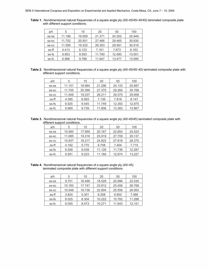
Table 1. Nondimensional natural frequencies of a square angle ply (45/-45/45/-45/45) laminated composite plate with different support conditions.
a/h 5 10 20 50 100
ss-ss 11.196 19.059 21.371 24.302 25.949 ss-sc 11.752 20.501 27.466 29.465 30.830 ss-cc 11.595 19.333 26.303 29.581 30.018 ss-ff 4.413 6.123 7.161 7.873 8.163 ss-fs 6.953 9.593 11.790 12.480 13.001 ss-fc 6.988 9.788 11.847 13.477 13.995
Table 2. Nondimensional natural frequencies of a square angle ply (45/-45/45/-45) laminated composite plate with different support conditions.
a/h 5 10 20 50 100
ss-ss 11.151 18.964 21.296 24.133 25.897 ss-sc 11.705 20.399 27.370 29.260 30.768 ss-cc 11.549 19.237 26.211 29.375 29.958 ss-ff 4.395 6.093 7.136 7.818 8.147 ss-fs 6.925 9.545 11.749 12.393 12.975 ss-fc 6.960 9.739 11.806 13.383 13.967
Table 3. Nondimensional natural frequencies of a square angle ply (45/-45/45) laminated composite plate with different support conditions.
a/h 5 10 20 50 100 ss-ss 10.560 17.959 20.167 22.854 24.524 ss-sc 11.085 19.318 25.919 27.709 29.137 ss-cc 10.937 18.217 24.822 27.818 28.370 ss-ff 4.162 5.770 6.758 7.404 7.715 ss-fs 6.558 9.039 11.126 11.736 12.287 ss-fc 6.591 9.223 11.180 12.674 13.227
Table 4. Nondimensional natural frequencies of a square angle ply (45/-45) laminated composite plate with different support conditions.
a/h 5 10 20 50 100
ss-ss 9.701 16.499 18.528 20.996 22.530 ss-sc 10.183 17.747 23.812 25.456 26.768 ss-cc 10.048 16.736 22.804 25.556 26.063 ss-ff 3.824 5.301 6.208 6.802 7.088 ss-fs 6.025 8.304 10.222 10.782 11.288 ss-fc 6.055 8.473 10.271 11.643 12.151
SEM X International Congress and Exposition on Experimental and Applied Mechanics, Costa Mesa, CA, June 7 – 10, 2004
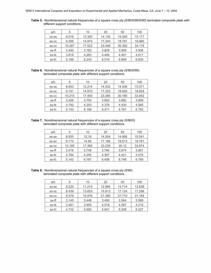
Table 5. Nondimensional natural frequencies of a square cross ply (0/90/0/90/0/90) laminated composite plate with different support conditions.
a/h 5 10 20 50 100
ss-ss 9.016 12.300 14.130 15.040 15.177 ss-sc 9.256 14.974 17.343 18.781 18.960 ss-cc 10.287 17.522 23.448 30.392 34.179 ss-ff 3.450 3.782 3.828 3.909 3.936 ss-fs 3.818 4.283 4.406 4.461 4.617 ss-fc 5.189 6.243 6.516 6.809 6.830
Table 6. Nondimensional natural frequencies of a square cross ply (0/90/0/90) laminated composite plate with different support conditions.
a/h 5 10 20 50 100 ss-ss 8.953 12.214 14.032 14.936 15.071 ss-sc 9.191 14.870 17.222 18.650 18.829 ss-cc 10.215 17.400 23.285 30.180 33.942 ss-ff 3.426 3.755 3.802 3.882 3.909 ss-fs 3.792 4.253 4.376 4.430 4.585 ss-fc 5.153 6.199 6.471 6.761 6.783
Table 7. Nondimensional natural frequencies of a square cross ply (0/90/0) laminated composite plate with different support conditions.
a/h 5 10 20 50 100 ss-ss 8.935 12.19 14.004 14.906 15.041 ss-sc 9.173 14.84 17.188 18.613 18.791 ss-cc 10.195 17.365 23.239 30.12 33.874 ss-ff 3.419 3.748 3.794 3.874 3.901 ss-fs 3.784 4.245 4.367 4.421 4.576 ss-fc 5.143 6.187 6.458 6.748 6.769
Table 8. Nondimensional natural frequencies of a square cross ply (0/90) laminated composite plate with different support conditions.
a/h 5 10 20 50 100 ss-ss 8.220 11.215 12.884 13.714 13.838 ss-sc 8.439 13.653 15.813 17.124 17.288 ss-cc 9.379 15.976 21.380 27.710 31.164 ss-ff 3.145 3.448 3.490 3.564 3.589 ss-fs 3.481 3.905 4.018 4.067 4.210 ss-fc 4.732 5.692 5.941 6.208 6.227
SEM X International Congress and Exposition on Experimental and Applied Mechanics, Costa Mesa, CA, June 7 – 10, 2004
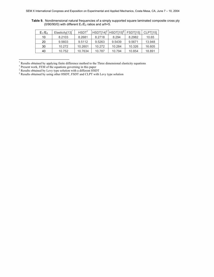
Table 9. Nondimensional natural frequencies of a simply supported square laminated composite cross ply (0/90/90/0) with different E1/E2 ratios and a/h=5.
E1 /E2 Elasticity[13]* HSDT† HSDT[14]‡ HSDT[15]§ FSDT[15] CLPT[15]
10 8.2103 8.2681 8.2718 8.294 8.2982 10.65 20 9.5603 9.5112 9.5263 9.5439 9.5671 13.948 30 10.272 10.2601 10.272 10.284 10.326 16.605 40 10.752 10.7634 10.787 10.794 10.854 18.891
* Results obtained by applying finite difference method to the Three dimensional elasticity equations † Present work, FEM of the equations governing in this paper ‡ Results obtained by Levy type solution with a different HSDT § Results obtained by using other HSDT, FSDT and CLPT with Levy type solution
SEM X International Congress and Exposition on Experimental and Applied Mechanics, Costa Mesa, CA, June 7 – 10, 2004