moca melter - trico poly systems€¦ · moca melter manual rev. g 3 safety warning – hazard of...
TRANSCRIPT
TRICO POLY SYSTEMS LLC.
60 BROWN AVE. SPRINGFIELD, NJ 07081 (973) 376-7770
MOCA MELTER
OPERATION MANUAL Rev G - February 2012
W/ 3/8 LL Probes

MOCA Melter Manual Rev. G
2
TRICO POLY SYSTEMS, LLC.
60 BROWN AVE., SPRINGFIELD, NEW JERSEY 07081, USA
Table of Contents
Safety 3
Installation 4
Power Requirements 4
General Operation 4
Loading 5
Venting Valve Assembly 5
Liquid Level Probes 7
Temperature Controllers 8
Grid Control 8
Grid Controller Calibration 9
Control Switches 9
Run Mode 10
Shut Down 11
Emptying 11
Alarms 11
PLC I/O 12
Temperature Control Settings 13
Grid Control Settings 14
Maintenance 15
Troubleshooting 16
Drawing List 18

MOCA Melter Manual Rev. G
3
SAFETY
WARNING – HAZARD OF ELECTRIC SHOCK
Any installation involving electric heaters, mechanical equipment, motors, etc. must be
effectively grounded in accordance with the national electrical code to eliminate shock hazard.
All electrical wiring to electrical equipment must be installed in accordance with the National
Electrical Code, or local electrical codes by a qualified person. For maximum equipment
protection, the National Electrical Code recommends ground fault protection be provided for
the branch circuit supplying electrical equipment.
NOTE: It is required that the end user must provide and wire a fused disconnect in close
proximity to each piece of electrical equipment provided by TRICO POLY SYSTEMS, LLC.
WARNING – MECHANICAL, AND OR CHEMICAL HAZARD
Equipment involving heaters, motors, gears, pumps, hoses, powered by air and, or fluids, in or on
equipment, provided by TRICO POLY SYSTEMS, LLC must be operated or serviced by
authorized personal only. Proper personal safety equipment, energy lock-outs, and proper tools
must be used at all times.
Proper handling, ventilation, and or, breathing apparatus may be required to operate, the
TRICO POLY SYSTEMS’ equipment if toxic chemicals are used in the manufacture of products
from this equipment.
MATERIAL SAFETY DATA SHEETS ARE TO BE MONITORED AT ALL TIMES.
WARNING – BURN RISK / PRESSURE BUILD-UP If the Melter is being shipped as a stand alone tank with a discharge line and a discharge
ball valve, there are several very important steps for shutting down the melter. A pressure
build-up and burn risk at the discharge ball valve is present if the following steps are not
taken. The scenario assumes the end of production for the day with the melter pressurized
and at processing temperature:
1. Close both the base and discharge ball valves.
2. Relieve pressure from the tank.
3. Once pressure is relieved, open only the discharge ball valve (use caution as some
residual MOCA may be present, and under pressure.
4. Turn off main power.
5. Be sure to leave the discharge ball valve open for the cool down and next start-
up/melt-out.
Note: If the discharge line is left full of MOCA and under pressure and allowed to cool;
upon remelting, extreme pressures of 500 PSI or greater can occur causing line failure and
or personal injury.

MOCA Melter Manual Rev. G
4
INSTALLATION Move the Melter to the intended permanent location. Carefully remove it from the crate.
Locate the Melter as close as possible to the machine. Check the length of the heated line
to insure proper location of the equipment. Heated lines should NOT touch the floor.
The Melter must be level and securely bolted to the floor.
Connect the air supply line from the metering machine or independent source to the top
assembly. Do not pressurize yet. See Venting Valve Assembly – page 5.
Caution: Any person operating this equipment should be aware of the potential hazards
that exist with the total chemical system your company has selected and the mechanical
environment that your company has selected to operate the equipment in. Check with your
Chemical Supplier and Safety Department prior to operating this equipment. Under no
condition should this equipment be used at elevated temperatures approaching or
exceeding the auto ignition temperature of the material stored or contained in or being
processed in the area selected by your company.
POWER REQUIREMENTS Electrical power for the control panel is brought in through the empty cord grip on the upper
right side of the enclosure. Please refer to the TPS nameplate on each respective MOCA Melter
for voltage and amperage requirements. Electrical connections should be performed by a
licensed electrician.
GENERAL OPERATION The MOCA Melter is designed to provide three main functions:
1. Melt MOCA on demand.
2. Maintain a small reservoir of liquid MOCA.
3. Maintain an optimum safe processing temperature.
Caution: MOCA violently decomposes when exposed to excessive temperatures. In no
case should MOCA ever be allowed to heat above 285°F (140°C).
The MOCA Melter is an “intelligent” tank, designed to provide liquid MOCA on demand. It is
composed of two sections separated by a heating grid. The lower portion of the tank contains a
small reservoir of liquid MOCA. Above the reservoir there is a Grid assembly that holds the
MOCA pellets in the upper part of the tank. In normal operation, the tank is under pressure. As
liquid MOCA is dispensed from the reservoir, a liquid level sensor triggers on “control” level;
which then causes the Grid to heat up and melt the pellets. As the reservoir level rises, the probe
triggers off; which then causes the Grid heater to turn off and the melting process stops. Liquid
MOCA is dispensed from a ball valve that is connected to the lower portion of an assembly
called the “base plug”.

MOCA Melter Manual Rev. G
5
LOADING MOCA is loaded by gravity through the 3 inch opening on the top of the tank. The tank holds up
to 400 lbs. of dry MOCA. Minimally, there should be 8 inches of MOCA covering the Grid.
Loading of MOCA requires the removal of the Venting Valve Assembly. This assembly has two
lock levers on either side that should be securely fastened prior to pressurization.
VENTING VALVE ASSEMBLY Once the desired amount of MOCA has been loaded, insert the Venting Valve assembly and
pressurize the tank. Typical operational pressure is between 30-40 PSI. The venting valve
assembly in installed at the top of the melter’s tank. It contains a pressure relief valve and a
filter.
NOTE: The MOCA Melter should only be pressurized with Nitrogen or dry air. Any
degree of moisture present in the MOCA Melter will have a darkening effect on the molten
MOCA.
Pressurizing
Figure 1 on the next page shows the assembly of the venting valve. Locate the fitting marked
“12” on the drawing. The melter is pressurized via this fitting.
Venting
The melter is vented via the fitting marked “19”. To vent, locate the valve marked “14” and
press its button.
Safety Aside from the standard pressure relief valve installed on the top portion of the melter’s tank,
there is a relief valve assembly composed of the following items (refer to drawing): 4, 8, 11, 13-
18, and 21.
In normal operation, both sides of the diaphragm (13) have the same pressure (from the pressure
source). In the event that the melter builds up pressure that exceeds the source’s pressure, the
pressure in the melter will cause the diaphragm to flex. This creates a path for the excess
pressure to be relieved (via the exhaust fitting – 19).
Caution: MOCA violently decomposes when exposed to excessive temperatures. In no
case should MOCA ever be allowed to heat above 285°F (140°C).
DO NOT OPERATE THE MELTER ABOVE 125°C.

MOCA Melter Manual Rev. G
6
Figure 1 – Venting Valve Assembly
MOCA Melter Manual Rev. G
7
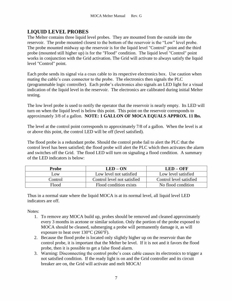
LIQUID LEVEL PROBES The Melter contains three liquid level probes. They are mounted from the outside into the
reservoir. The probe mounted closest to the bottom of the reservoir is the “Low” level probe.
The probe mounted midway up the reservoir is for the liquid level "Control" point and the third
probe (mounted still higher up) is for the "Flood" condition. The liquid level "Control" point
works in conjunction with the Grid activation. The Grid will activate to always satisfy the liquid
level "Control" point.
Each probe sends its signal via a coax cable to its respective electronics box. Use caution when
mating the cable’s coax connector to the probe. The electronics then signals the PLC
(programmable logic controller). Each probe’s electronics also signals an LED light for a visual
indication of the liquid level in the reservoir. The electronics are calibrated during initial Melter
testing.
The low level probe is used to notify the operator that the reservoir is nearly empty. Its LED will
turn on when the liquid level is below this point. This point on the reservoir corresponds to
approximately 3/8 of a gallon. NOTE: 1 GALLON OF MOCA EQUALS APPROX. 11 lbs.
The level at the control point corresponds to approximately 7/8 of a gallon. When the level is at
or above this point, the control LED will be off (level satisfied).
The flood probe is a redundant probe. Should the control probe fail to alert the PLC that the
control level has been satisfied; the flood probe will alert the PLC which then activates the alarm
and switches off the Grid. The flood LED will turn on signaling a flood condition. A summary
of the LED indicators is below:
Probe LED – ON LED – OFF
Low Low level not satisfied Low level satisfied
Control Control level not satisfied Control level satisfied
Flood Flood condition exists No flood condition
Thus in a normal state where the liquid MOCA is at its normal level, all liquid level LED
indicators are off.
Notes:
1. To remove any MOCA build up, probes should be removed and cleaned approximately
every 3 months in acetone or similar solution. Only the portion of the probe exposed to
MOCA should be cleaned, submerging a probe will permanently damage it, as will
exposure to heat over 130°C (266°F).
2. Because the flood probe is located only slightly higher up on the reservoir than the
control probe, it is important that the Melter be level. If it is not and it favors the flood
probe, then it is possible to get a false flood alarm.
3. Warning: Disconnecting the control probe’s coax cable causes its electronics to trigger a
not satisfied condition. If the ready light is on and the Grid controller and its circuit
breaker are on, the Grid will activate and melt MOCA!

MOCA Melter Manual Rev. G
8
4. Warning: Disconnecting the flood probe’s coax cable causes its electronics to trigger a no
flood condition. Therefore, if it is left disconnected and a real flood condition exists, the
PLC will not know and the alarm will not turn on!
TEMPERATURE CONTROL There are two temperature controllers on the Melter. The controllers are located in the control
panel. The pushbuttons directly below each controller turn power on/off and also reset any
temperature alarm. The reservoir temperature controller maintains temperature on the lower
portion of the Melter’s tank: the reservoir. The base controller maintains temperature on the
Melter’s “base plug”. This is an assembly that begins with the discharge ball valve (at the
bottom of Melter) and runs through the center of the reservoir up to the Grid. Each controller
has a dedicated temperature sensor. Once the setpoint is programmed in the controller, no
further adjustment is required. The nominal operating temperature should be from 115 to 125°C
(239-257°F).
An LED indicator labeled “Ready” will turn on once the reservoir reaches its setpoint. This is an
indication that the reservoir temperature sensor has reached its setpoint. This however, does not
mean that the entire reservoir has reached temperature. An additional time of approximately 30
minutes should be allowed for the reservoir to completely melt out.
GRID CONTROL The Grid controller displays the current/voltage relationship of the Grid. It does not display
temperature. This controller (although it is the same model as the other controllers) displays a
milli-volt signal.
When the Grid is powered, the current and voltage at the Grid are measured using the two
converters inside the control panel. This circuit produces a millivolt signal that is sent to the Grid
Controller. Because each customer’s facility will have a different line voltage, and the heating
element in the Grid can vary from 6.9 to 7.5 Ohms, the number displayed on the controller while
the Grid is powered will range from approximately 25 to 39.
The controller displays the Grid’s current/voltage relationship and alarms and shuts off power if
the Grid becomes too hot. As the temperature of the Grid increases, so does its resistance
(ohms). This condition occurs when the Grid is not completely covered with MOCA pellets. As
resistance increases, the current draw decreases. The Grid’s measurement circuit compares the
current and voltage signals. It subtracts the voltage signal from the current signal and the
controller displays this difference. If the current decreases then the overall signal increases
because the voltage at the Grid is constant. If the signal level rises beyond the setpoint, the
controller alarms and the PLC switches off the Grid’s power relays.
GRID CONTROLLER CALIBRATION
When the Grid is unpowered, the display will read approximately zero (no current flow). As the
liquid level of MOCA is depleted, the PLC will “activate” the Grid. This activation consists of
enabling the Grid’s power SSRs (solid state relays) thus melting the MOCA pellets on the Grid.

MOCA Melter Manual Rev. G
9
The melting pellets flow through open spaces between the spiral wrap of the Grid and fall into
the reservoir. Assuming there is a minimum of 6-8 inches of MOCA pellets on the Grid, the
controller display will rise from zero to a number between 25 and 39. This number will increase
slowly until the Grid temperature becomes stable and the melt rate of MOCA is constant.
Follow the steps for proper calibration:
1. To calibrate this controller, it must have the correct settings (see Grid controller settings).
2. All pressure must be vented from the tank.
3. The lower line must be disconnected from the discharge ball valve.
4. Place a one gallon container under the ball valve.
5. Once the Melter has at least 6-8 inches of MOCA pellets covering the Grid and the
reservoir and base are at operating temperature, the ball valve can be opened.
6. MOCA will begin to flow out and the Grid should activate. Once the number displayed
stabilizes, the setpoint can then be set. The setpoint entered should be the stabilized
number with an addition of 0.5. This effectively, is the over temperature setpoint. If for
any reason the Grid becomes exposed anywhere, the resistance of the Grid element will
rise and the display will rise and trip the setpoint. Should this occur, shut down the
Melter and investigate.
Note: Once calibration is complete, the Grid controller's alarm setpoint should never be
changed. The only time this alarm setpoint should be changed is if there is a change in
input power to the melter (from 208 to 240VAC for example) or if the Grid is replaced. If
the Grid alarm goes on, this means that some area of the Grid is exposed. You should stop
and investigate. See the troubleshooting section.
Note: As long as the Grid is completely covered with pellets and activated, the actual
temperature of the Grid will remain between 104°C to 107°C.
CONTROL SWITCHES Grid Activate Switch
The Grid Activate Switch when depressed activates the Grid circuit and powers up the
Controller. The following conditions are necessary for the Grid to turn on:
1. The Grid heater circuit breaker is on.
2. The liquid level control sensor is calling for more material.
3. The Melter reservoir is up to setpoint (“Ready” light is illuminated).
4. The Grid is not in an over-temperature condition.
Alarm Reset Switch
The Alarm Reset Switch is used to reset an alarm condition. When the alarm sounds, depress the
reset switch momentarily to silence the audible alarm. This action simply disables the audible
alarm; the operator must investigate the cause for the alarm.
Digital Temperature Controller Switches
The Temperature Controller Switches are mounted directly under each controller. When the
switch is depressed to the "ON" position, power is supplied to the controller. The switch also
functions as an "Alarm Reset" when there is an under/over temperature alarm condition.

MOCA Melter Manual Rev. G
10
RUN MODE – From a Cold Start 1. Turn on main power to the Melter by turning the main power disconnect switch to on. It
is located in the upper right corner of the control panel. Verify all circuit breakers are on.
2. Verify the Grid controller is turned off.
3. Pressurize the Melter with dry air or nitrogen at 30-40 PSI.
4. The Melter requires approximately 45 minutes to melt the entire reservoir from a cold
start. When the reservoir temperature is at setpoint, the "READY" light will illuminate.
The "READY" light indicates that the Grid heater may now activate, if necessary.
5. The base temperature controller is independent of logic control. By being independent, it
allows the operator to maintain heat on the base when the reservoir heat is not required.
For normal operation, it should be on.
6. When the "READY" light is illuminated and the initial warm up period has elapsed, the
Grid controller can be turned on. In a normal start up, the reservoir will already have
MOCA from the previous day’s production. As the reservoir temperature increases, the
MOCA will slowly melt into the liquid state. If the “READY” light is on and the
warm up period has not elapsed, DO NOT turn on the Grid controller. As the
reservoir temperature increases, the MOCA will transition from the solid to liquid
state. During this period it is possible for the control probe to falsely switch to a not
satisfied state. If the Grid controller was on and the Control probe is not satisfied,
the PLC will enable the Grid to turn on and melt MOCA. This will cause the new
MOCA to fall onto the unmelted MOCA in the reservoir and cause a flood
condition. Always wait for the “READY” light to be on and the additional warm up
period. 7. Whenever liquid level is not satisfied, the Grid will activate and melt more MOCA as
needed to satisfy the liquid level control point. The Grid will turn on/off automatically as
required. Recall that the Grid’s controller displays the Grid’s current/voltage relationship.
8. When liquid level is satisfied, the operator can open the discharge ball valve located on
the bottom of the base plug. Use caution as the base plug and ball valve are very hot. The
ball valve must have a heated material transfer line connected to it. The other end of the
line is connected to a metering pump or other process equipment. Be aware that since the
tank is under pressure, once the ball valve is opened, liquid MOCA will flow. The Grid
is capable of a melt rate of 4 lbs./minute at 240 VAC. The Reservoir holds approximately
10 lbs. of liquid MOCA.
The Melter can be run indefinitely, so long as there are pellets in the upper tank. When the time
comes for re-loading the Melter, follow the shutdown procedure.
MOCA Melter Manual Rev. G
11
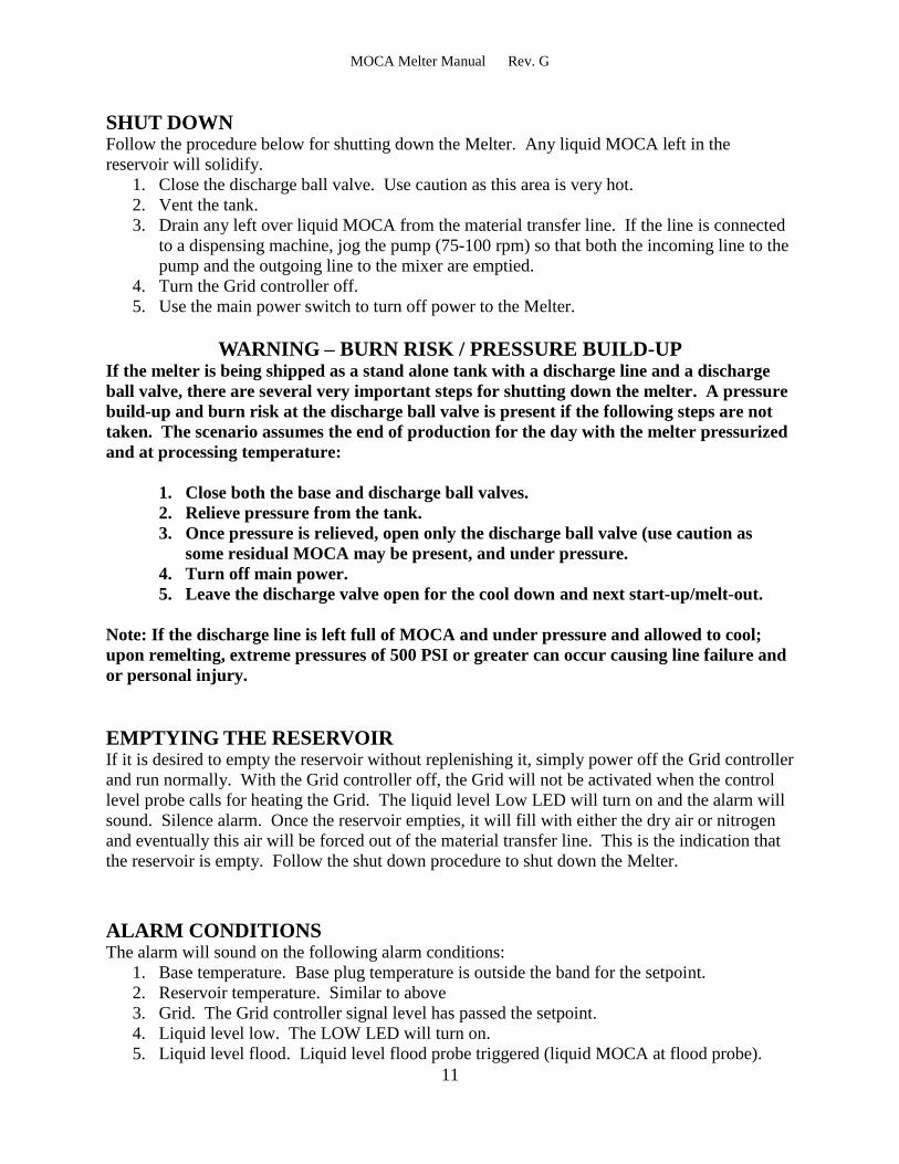
SHUT DOWN Follow the procedure below for shutting down the Melter. Any liquid MOCA left in the
reservoir will solidify.
1. Close the discharge ball valve. Use caution as this area is very hot.
2. Vent the tank.
3. Drain any left over liquid MOCA from the material transfer line. If the line is connected
to a dispensing machine, jog the pump (75-100 rpm) so that both the incoming line to the
pump and the outgoing line to the mixer are emptied.
4. Turn the Grid controller off.
5. Use the main power switch to turn off power to the Melter.
WARNING – BURN RISK / PRESSURE BUILD-UP If the melter is being shipped as a stand alone tank with a discharge line and a discharge
ball valve, there are several very important steps for shutting down the melter. A pressure
build-up and burn risk at the discharge ball valve is present if the following steps are not
taken. The scenario assumes the end of production for the day with the melter pressurized
and at processing temperature:
1. Close both the base and discharge ball valves.
2. Relieve pressure from the tank.
3. Once pressure is relieved, open only the discharge ball valve (use caution as
some residual MOCA may be present, and under pressure.
4. Turn off main power.
5. Leave the discharge valve open for the cool down and next start-up/melt-out.
Note: If the discharge line is left full of MOCA and under pressure and allowed to cool;
upon remelting, extreme pressures of 500 PSI or greater can occur causing line failure and
or personal injury.
EMPTYING THE RESERVOIR If it is desired to empty the reservoir without replenishing it, simply power off the Grid controller
and run normally. With the Grid controller off, the Grid will not be activated when the control
level probe calls for heating the Grid. The liquid level Low LED will turn on and the alarm will
sound. Silence alarm. Once the reservoir empties, it will fill with either the dry air or nitrogen
and eventually this air will be forced out of the material transfer line. This is the indication that
the reservoir is empty. Follow the shut down procedure to shut down the Melter.
ALARM CONDITIONS The alarm will sound on the following alarm conditions:
1. Base temperature. Base plug temperature is outside the band for the setpoint.
2. Reservoir temperature. Similar to above
3. Grid. The Grid controller signal level has passed the setpoint.
4. Liquid level low. The LOW LED will turn on.
5. Liquid level flood. Liquid level flood probe triggered (liquid MOCA at flood probe).

MOCA Melter Manual Rev. G
12
PLC I/O DISPLAY The front of the PLC has eight inputs. This indicates the status of the input signals at any time.
The PLC controls four outputs.
Input 1 Controller temperature alarm condition
Input 2 Alarm reset switch
Input 3 Reservoir temperature controller is calling for the PLC to energize the reservoir
solid state relay.
Input 4 Grid controller is powered ON
Input 5 Liquid Level is low – yellow indicator ON
Input 6 Liquid Level control is NOT satisfied – yellow indicator ON
Input 7 Flood condition – red indicator ON
Input 8 Reservoir temperature controller is powered ON
Output 1 Grid heater is ON (melting MOCA)
Output 2 Reservoir heater is ON
Output 3 "Ready" light is illuminated (reservoir has reached setpoint)
Output 4 Audible alarm is energized

MOCA Melter Manual Rev. G
13
TEMPERATURE CONTROL SETTINGS (RESV. & BASE)
CAL 3300 Program
LEVEL 1 LEVEL 2 LEVEL 3
Tune OFF SP1.P -- SP1.d SSd
bAnd 10 (18) bAnd OFF SP2.d rLY
int.t 5 PL.1 100 Burn uP.SC
dEr.t 25 PL.2 100 rEU.d 1r.2r
dAC 1.5 SP2.A bAnd rEU.L 1n.2n
CYC.t 20 SP2.b Lt.ho SPAn -56 (-101)
oFSt 0 diSP 1 Zero 15 (27)
SP.Lk OFF hi.SC 150 (302) ChEK Off
SPrr 0 Lo.SC 0 (32) rEAD --
SPrn OFF inPt RTD dATA CTA
SoAk -- Unit °C (°F) Ver (factory set)
Set.2 8 (14) rESET (see below)
Bnd.2 0.1 (0.2)
CYC.2 ON.OFF
LEVEL 4 - DO NOT ALTER: USE DEFAULT SETTINGS ONLY
GENERAL INFO:
1. These settings, when entered on all new units will configure both outputs properly and
calibrate the unit for the special RTD temperature control. There should be no need to
make any additional adjustments.
2. Set.2 represents the upper/lower band for alarm purposes. This input can be adjusted by
the operator for individual applications. The factory hysteresis is 8°C.
3. After setting all initial parameters and entering a setpoint, then tune at setpoint should
run, this will tune the heating and pick the new P.I.D settings for SP1.
4. For the rESET setting, “all” should only be used to completely reset the controller in the
event that a total reprogram is needed.
5. All temperature controllers have the same program and are interchangeable. Default
settings are for a temperature reading in degrees Celsius. The settings above in ( ) are for
a reading in degrees Fahrenheit.
6. To silence Alarm and reset, depress white button below Controller. Depress once to turn
Controller OFF and depress again to turn Controller ON.
7. Temperature Controllers are capable of various programs depending on customer's
application i.e. over-temperature only etc...

MOCA Melter Manual Rev. G
14
ENTERING ADJUSTMENTS
1. To enter a new setpoint, depress the * button. The unit of measure will appear first, then
the present setpoint. While depressing the * button, depress the up or down scroll button
to desired setpoint temperature.
2. To enter the program (Level 1, Level 2, Level 3), depress both scroll buttons
simultaneously for three seconds. The word " tune " will appear on the display. This is
the first entry on Level 1. To scroll to each input, depress either the up or down scroll
button. To change an input, depress the * button and scroll up/down with the scroll
buttons.
GRID CONTROL SETTINGS
CAL 3300 Program
LEVEL 1 LEVEL 2 LEVEL 3
Tune OFF SP1.P -- SP1.d SSd
bAnd 0.1 bAnd OFF SP2.d rLY
int.t OFF PL.1 100 Burn uP.SC
dEr.t 25 PL.2 100 rEU.d 1d.2r
dAC 1.5 SP2.A du.hi rEU.L 1n.2n
CYC.t ON.OFF SP2.b Ltch SPAn 20
oFSt 0 diSP 0.1 Zero 0.1
SP.Lk OFF hi.SC 50 ChEK Off
SPrr 0 Lo.SC 0.0 rEAD --
SPrn OFF inPt Lin 1 dATA CTA
SoAk -- Unit set Ver (factory set)
Set.2 0 rESET (see below)
Bnd.2 2.0
CYC.2 ON.OFF
LEVEL 4 - DO NOT ALTER: USE DEFAULT SETTINGS ONLY
Settings are entered the same way as on the temperature controllers.

MOCA Melter Manual Rev. G
15
MAINTENANCE
Liquid Level Probes
Approximately every 6 months remove the probes. Clean and inspect the probe (use an acetone
or similar solution) being careful to not get any liquid on the connector side.
Visually inspect both the probe connector and the coax cable connector and use caution when
mating the connectors (do not force them together).
Grid
Normally no maintenance is required for the Grid. However, if a Grid controller alarm occurs, it
is recommended that the melter’s tank be removed in the very near future. Remove any
remaining MOCA pellets and visually inspect the Grid. Any blackening of the Grid or any built
up MOCA should be removed and cleaned with an acetone or similar solution. Do not pour the
solution onto the Grid as it will leak through the Grid element and fall into the reservoir. Instead
dip a cloth into the solution and clean the Grid in sections. If it is necessary to remove the Grid,
follow this procedure:
1. Verify that melter is unpressurized.
2. Loosen all clamps securing the melter tank from the melter reservoir.
3. Remove melter tank. The Grid assembly is visible once the tank is removed.
Use proper protective equipment to handle any moca left on the Grid.
4. If the Grid has phenolic supports on the perimeter, remove the outside gasket.
5. Remove center cap.
6. Remove the insulation on the two connections. These are split bolt connectors.
Remove the split bolts.
7. Loosen and remove the three allen bolts securing the Grid assembly to the base
plug assembly (central aluminum support).
8. Lift off Grid assembly. This completes the procedure.
MOCA Melter Manual Rev. G
16
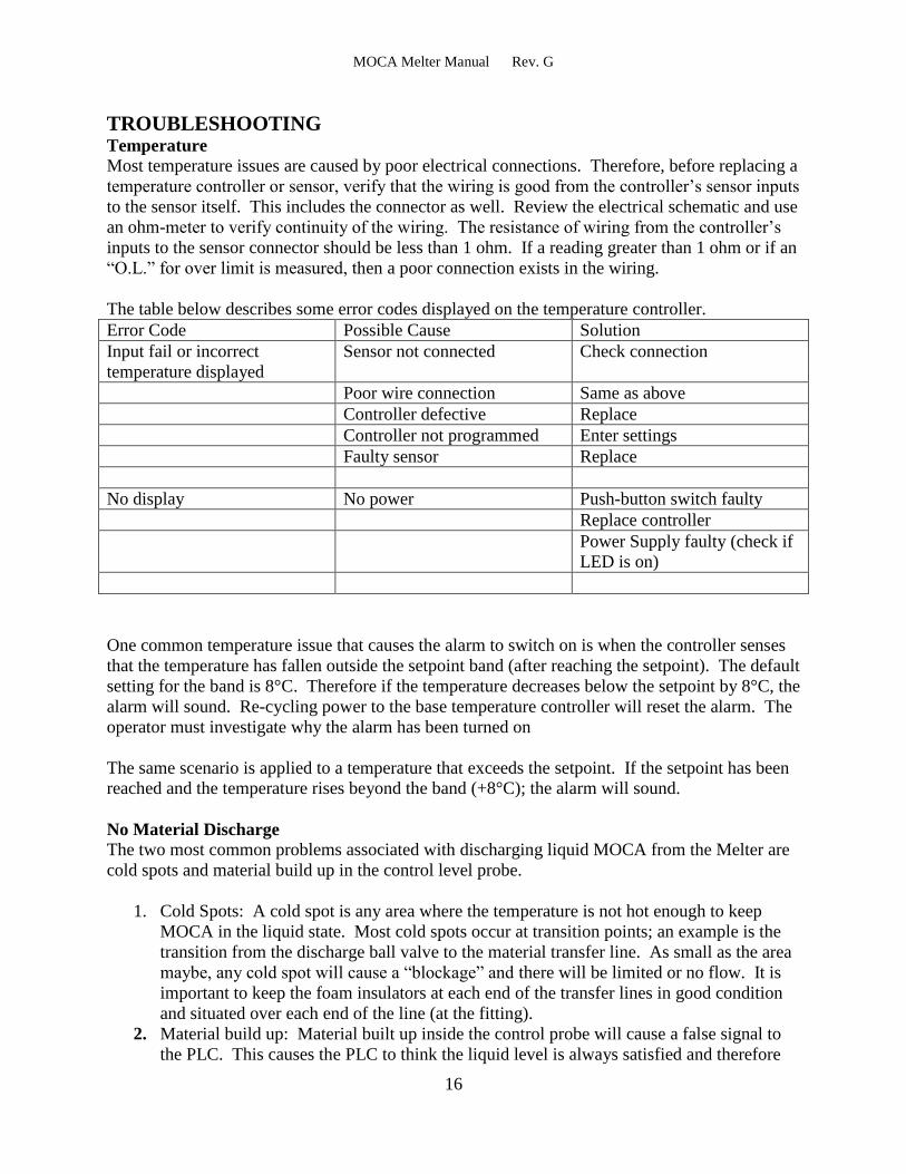
TROUBLESHOOTING Temperature
Most temperature issues are caused by poor electrical connections. Therefore, before replacing a
temperature controller or sensor, verify that the wiring is good from the controller’s sensor inputs
to the sensor itself. This includes the connector as well. Review the electrical schematic and use
an ohm-meter to verify continuity of the wiring. The resistance of wiring from the controller’s
inputs to the sensor connector should be less than 1 ohm. If a reading greater than 1 ohm or if an
“O.L.” for over limit is measured, then a poor connection exists in the wiring.
The table below describes some error codes displayed on the temperature controller.
Error Code Possible Cause Solution
Input fail or incorrect
temperature displayed
Sensor not connected Check connection
Poor wire connection Same as above
Controller defective Replace
Controller not programmed Enter settings
Faulty sensor Replace
No display No power Push-button switch faulty
Replace controller
Power Supply faulty (check if
LED is on)
One common temperature issue that causes the alarm to switch on is when the controller senses
that the temperature has fallen outside the setpoint band (after reaching the setpoint). The default
setting for the band is 8°C. Therefore if the temperature decreases below the setpoint by 8°C, the
alarm will sound. Re-cycling power to the base temperature controller will reset the alarm. The
operator must investigate why the alarm has been turned on
The same scenario is applied to a temperature that exceeds the setpoint. If the setpoint has been
reached and the temperature rises beyond the band (+8°C); the alarm will sound.
No Material Discharge
The two most common problems associated with discharging liquid MOCA from the Melter are
cold spots and material build up in the control level probe.
1. Cold Spots: A cold spot is any area where the temperature is not hot enough to keep
MOCA in the liquid state. Most cold spots occur at transition points; an example is the
transition from the discharge ball valve to the material transfer line. As small as the area
maybe, any cold spot will cause a “blockage” and there will be limited or no flow. It is
important to keep the foam insulators at each end of the transfer lines in good condition
and situated over each end of the line (at the fitting).
2. Material build up: Material built up inside the control probe will cause a false signal to
the PLC. This causes the PLC to think the liquid level is always satisfied and therefore

MOCA Melter Manual Rev. G
17
the PLC never activates the Grid. This condition empties the reservoir. Pressurized air
coming from the line with no liquid MOCA is the effect you see. It is important to
inspect the probes every 6 months. Any build up should be removed. DO NOT OVER
OR UNDER TIGHTEN THE PROBE; PERMANENT DAMAGE WILL OCCUR.
Flood Condition
A flood condition will result from several issues:
1. Material build up; this is described above.
2. Melter not being level
3. Control probe fault
4. Not waiting for the appropriate warm up time.
Since the flood probe is only slightly positioned further out on the reservoir with respect to the
control probe; any tendency for the Melter to favor the flood probe side could cause a false flood
condition. It is important to mount the Melter so that it is level.
A faulty control probe may cause the Grid to continue melting above the control level and
subsequently cause a flood condition (via flood probe). To test, see procedure on the next page.
A flood condition may also occur when the Melter’s reservoir is full and powered up from a cold
start. The Ready light is an indication that the reservoir has reached temperature, but not an
indication that the entire reservoir has melted out. When the Melter is powered up from a cold
start the control probe may initially switch to a not satisfied state. If the Grid controller is
powered on, the Grid will heat up and thus the liquid level in the reservoir will rise. This
eventually causes the flood probe to trigger a flood condition. To prevent this, keep the Grid
controller powered off until the initial warm up period has elapsed. Once the initial warm up
period has expired and both the Low and Control LEDs signal that the level is satisfied, the Grid
controller may be powered on indefinitely.
Probe Test
A test of any probe can be performed by removing the probe from the reservoir. Before
attempting this however, verify that the Melter has been vented and the reservoir is empty.
Note: Turn power off when disconnecting/connecting the probe’s connector.
With the probe out of the reservoir and connected to its coax cable; dip the tip into a cup of
water. The probe will switch and should change the state of the PLC input and LED indicator as
you submerge the probe tip into the water. Removing it from the water causes the state to
change back. See table below:
PLC Input Probe in water Probe out of water
Low – Input 5 Level satisfied – Input & LED off Level not satisfied – Input & LED on
Control – Input 6 Level satisfied – Input & LED off Level not satisfied – Input & LED on
Flood – Input 7 Flood condition – Input & LED on No flood condition – Input & LED off
If the probe does not seem to work, keep in mind that there could be a problem with the cable. If
this is suspected, test the probe with the other cable keeping in mind that the function will now

MOCA Melter Manual Rev. G
18
reverse as the control and flood inputs operate in opposite states.
Grid Controller Alarm The Grid controller will alarm when the reading reaches the alarm setpoint. This indicates that
the Grid’s resistance is increasing. There are two typical reasons for this to occur: one is that the
melter tank is empty of MOCA pellets, the second is that a MOCA bridge exists.
A MOCA bridge is an area of MOCA pellets that clumps together and prevents the pellets from
resting on the Grid. This resembles a bridge and thus exposes an area of the Grid. An exposed
area causes the Grid’s resistance to rise (while powered on). If the resistance rises, the current
drawn by the Grid will decrease and since the Grid controller measures the Grid’s
current/voltage signal (and since the voltage remains the same); the Grid controller reading will
increase and eventually reaches the alarm setpoint. This then causes the PLC to command off
the relays that route power to the Grid. A totally or partially exposed Grid (if allowed to be
powered on) will eventually overheat and damage itself.
If a MOCA bridge is suspect, turn off main power and vent the melter. Remove the venting
valve assembly and use a “soft” rod (a wooden broom handle for example) to gently feel your
way to the Grid. Move the rod slowly back and forth. A bridge will cause the rod to want to
move up. A bridge can be broken up by a gentle hammering motion. The Grid element is
robust, but it will be damaged by a rough pounding (use caution). The only way to be absolutely
sure that no bridges exist, is to remove the melter’s upper tank and visually inspect the Grid.
Grid Controller Reading As described in the Grid Control section, the controller’s reading will be 25 to 39 (Grid on).
As an example, if the controller displays 30 while melting MOCA, the setpoint alarm will be set
to 30.5. A reading higher than 30.5 indicates that there is an exposed area on the Grid (MOCA
bridge) or simply that the melter has run out of pellets. A controller reading of any number other
than 0 (Grid off) or approximately 30 (Grid on) indicates a problem. If the Grid is commanded
on and a reading of 18 is displayed, this indicates a problem with either the voltage supply
(incoming voltage less than 208-240VAC) or higher than normal Grid resistance (possibly a
wiring issue or bad contact). A controller reading of a negative number (-60 for example)
indicates a problem with the Grid’s voltage/current measurement circuit or the SSRs. If this is
left unchecked and the Grid is run until the pellet level is down to zero, there is no way for the
alarm to activate and permanent damage may be done to the Grid. In either case, it is important
to periodically check the Grid controller display and verify its reading is approximately 30.
DRAWING LIST The Melter’s control panel assembly drawing is 21273-6. Refer to the notes section for probe
and temperature sensor part numbers. The Melter’s electrical schematic drawing is H-2007.

MOCA Melter Manual Rev. G
19
(OPTIONAL) Vacuum Transfer OPERATION INSTRUCTIONS
Note: The vacuum transfer system causes to Moca Melter to become extremely top heavy.
The unit’s three legs MUST be bolted to the floor.
Loading Pellets
1. Relieve all pressure from the tank by pushing the vent button (item 14) on the Vent/
pressure assembly. The 3/8” fitting should be exhausted outside in accordance with your
local and company policies. Pull open the brass 75psi relief valve located on the top of
the tank to ensure no pressure is left and double check the pressure guage is at zero.
2. Check the pellet level by removing the Vent/Pressure valve assembly held in place by the
two cam lock levers.
3. The transfer rate is approximately 25-30 lbs per minute.
4. Open the large 3” pellet inlet valve and close the base center plug discharge ball valve.
5. Set the inlet #1 control knob to 25-27 seconds and turn power on the transfer control box.
6. The vacuum will start, and begin pulling pellets from the supply container for 25-27
seconds then dump them into the Melter for 3 to 5 seconds. This process will continue
until the desired amount of pellets have been transferred. This can be verified by looking
in the vent/pressure valve port.
7. DO NOT OVERFILL PELLETS OR THE DUMP VALVE WILL STICK OPEN AND
REQUIRE DISASSEMBLY.
8. BE SURE NOT TO SUCK IN THE BAG LINER OF THE SUPPLY DRUM IF
APPLICABLE.
9. Should the transfer rate slow over time contact TPS for filter cleaning instructions.
Repressurization
1. Close the 3” fill valve and reinstall the vent/pressure assembly.
2. If the Melter is not up to operating temperature, do so prior to pressurization.
3. Apply 35 psi nitrogen pressure to the tank by adjusting the valve and or pressure
regulator.
4. Once a stable pressure is established reopen the center base discharge valve.
5. Molten Moca will now be ready to dispense.