kicksynthes.vo.llnwd.net/o16/llnwmb8/int mobile/synthes...1.3 intended use using the system intended...
TRANSCRIPT

KICKVersion 1.2
TECHNICAL USER GUIDE
REVISION 1.0
Copyright 2015, Brainlab AG Germany. All rights reserved.


TABLE OF CONTENTS
GENERAL INFORMATION ...................................................................................................5
Contact Data and Legal Information ......................................................................................................5
Legal Information .........................................................................................................................................6
Symbols .......................................................................................................................................................7
Hardware Symbols.......................................................................................................................................8
Intended Use .............................................................................................................................................11
Training and Documentation .................................................................................................................13
Documentation...........................................................................................................................................14
SYSTEM OVERVIEW ..............................................................................................................15
System Components ...............................................................................................................................15
Monitor Cart ..............................................................................................................................................17
3rd-Party Connections ...............................................................................................................................19
LAN Connection.........................................................................................................................................21
Camera Cart ..............................................................................................................................................22
Camera Volume .........................................................................................................................................25
TROUBLESHOOTING ............................................................................................................27
Introduction ...............................................................................................................................................27
Troubleshooting: Monitor Cart..............................................................................................................28
Troubleshooting: Camera Cart..............................................................................................................29
ELECTRICAL SAFETY ..........................................................................................................31
Classification ............................................................................................................................................31
Test Requirements ...................................................................................................................................32
Testing Overview........................................................................................................................................33
Recurrent Tests..........................................................................................................................................35
Performing Tests ......................................................................................................................................37
Leakage Current ........................................................................................................................................38
Insulation Resistance .................................................................................................................................40
Test Report ................................................................................................................................................41
TABLE OF CONTENTS
Kick Ver. 1.2 / Technical User Guide Rev. 1.0 / DePuy Synthes 3

COMPLIANCES AND SPECIFICATIONS .............................................................43
Electrical Standards ................................................................................................................................43
Environmental Requirements................................................................................................................44
System Specifications ............................................................................................................................45
Technical Specifications .............................................................................................................................47
Compliances .............................................................................................................................................48
General Electromagnetic Immunity ............................................................................................................49
Electromagnetic Immunity, Kick System.....................................................................................................50
RF Communications Equipment.................................................................................................................52
Tested Cables ............................................................................................................................................53
Hospital Network........................................................................................................................................54
Power Plugs ..............................................................................................................................................55
Regional Power Plugs................................................................................................................................56
USB Flash Drives .....................................................................................................................................57
MAINTENANCE ............................................................................................................................59
Inspections ................................................................................................................................................59
Inspections.................................................................................................................................................60
Annual Inspection by Brainlab....................................................................................................................61
Air Filter Exchange ..................................................................................................................................62
Damaged Equipment ...............................................................................................................................63
INDEX ....................................................................................................................................................65
TABLE OF CONTENTS
4 Kick Ver. 1.2 / Technical User Guide Rev. 1.0 / DePuy Synthes
1 GENERAL INFORMATION
1.1 Contact Data and Legal Information
Manufacturer
This product is manufactured by Brainlab and exclusively distributed by DePuy Synthes.
Brainlab AG
Kapellenstr. 12
85622 Feldkirchen
Germany
Distributor
DePuy Synthes Sales, Inc.
325 Paramount Drive
Raynham, MA 02767
USA
Support
If you cannot find information you need in this guide, or if you have questions or problems, contact
support:
Region Telephone and Fax
United States, Canada, Central and South Ameri-
caTel: +1 (866) 473 7823
Europe, Middle East, Africa Tel: +32 2 352 16 66
Asia, Australia Tel: +65 6827 6154
Expected Service Life
Brainlab provides a minimum of eight years of service for platforms. During this period of time,
spare parts as well as field support are offered.
The Kick system lifetime is dependent on factors such as method and duration of each use, and
handling between uses. Careful functional testing and inspection of the Kick system before use is
the best method for determining the end of lifetime.
The end of lifetime is normally determined by wear and tear damage due to use. As part of
preventive service, follow the maintenance instructions.
Feedback
Despite careful review, this guide may contain errors.
Please contact us at [email protected] if you have suggestions as to how we can
improve this guide.
GENERAL INFORMATION
Kick Ver. 1.2 / Technical User Guide Rev. 1.0 / DePuy Synthes 5

1.1.1 Legal Information
Copyright
This guide contains proprietary information protected by copyright. No part of this guide may be
reproduced or translated without express written permission of Brainlab.
Brainlab Trademarks
Kick® is a trademark of Brainlab AG in Germany and/or the US.
Non-Brainlab Trademarks
Intel® is a registered trademark of Intel Corporation in the US and other countries.
CE Label
• The CE label shows that the Brainlab product complies with the essential re-
quirements of Council Directive 93/42/EEC (the "MDD").
• According to the principles set out in the MDD, Council Device Directive 93/42/
EEC, Kick is a Class IIb product.
NOTE: The validity of the CE label can only be confirmed for products manufactured by Brainlab.
Disposal Instructions
Only dispose of electrical and electronic equipment in accordance with statutory regu-
lations. For information regarding the WEEE (Waste Electrical and Electronic Equip-
ment) directive, visit:
http://www.brainlab.com/weee
Sales in the US
US federal law restricts this device to sale by or on the order of a physician.
Federal Communications Commission (FCC) Statement
This equipment has been tested and found to comply with the limits for a Class A digital device,
pursuant to part 15 of the FCC Rules. These limits are designed to provide reasonable protection
against harmful interference when the equipment is operated in a commercial environment. This
equipment generates, uses, and can radiate radio frequency energy and, if not installed and used
in accordance with the instruction manual, may cause harmful interference to radio
communications. Operation of this equipment in a residential area is likely to cause harmful
interference in which case the user will be required to correct the interference at their expense.
Any changes or modifications not expressly approved by the party responsible for
compliance could void the user’s authority to operate this equipment.
This device complies with part 15 of the FCC Rules. Operation is subject to the following two
conditions: (1) This device may not cause harmful interference, and (2) this device must accept
any interference received, including interference that may cause undesired operation.
The WLAN module included in this product cannot be accessed by end users. The FCC ID of the
WLAN module is listed on the WLAN label attached to the Monitor Cart. Please contact Brainlab
authorized support in case of any related questions.
Contact Data and Legal Information
6 Kick Ver. 1.2 / Technical User Guide Rev. 1.0 / DePuy Synthes

1.2 Symbols
Symbols Used in This Guide
Warnings
Warnings are indicated by triangular warning symbols. They contain safety-critical
information regarding possible injury, death or other serious consequences associated
with equipment misuse.
Cautions
Cautions are indicated by circular caution symbols. They contain safety-critical information
regarding possible problems with the device. Such problems include device malfunctions,
device failure, damage to device or damage to property.
Notes
NOTE: Notes are formatted in italic type and indicate additional useful hints.
GENERAL INFORMATION
Kick Ver. 1.2 / Technical User Guide Rev. 1.0 / DePuy Synthes 7
1.2.1 Hardware Symbols
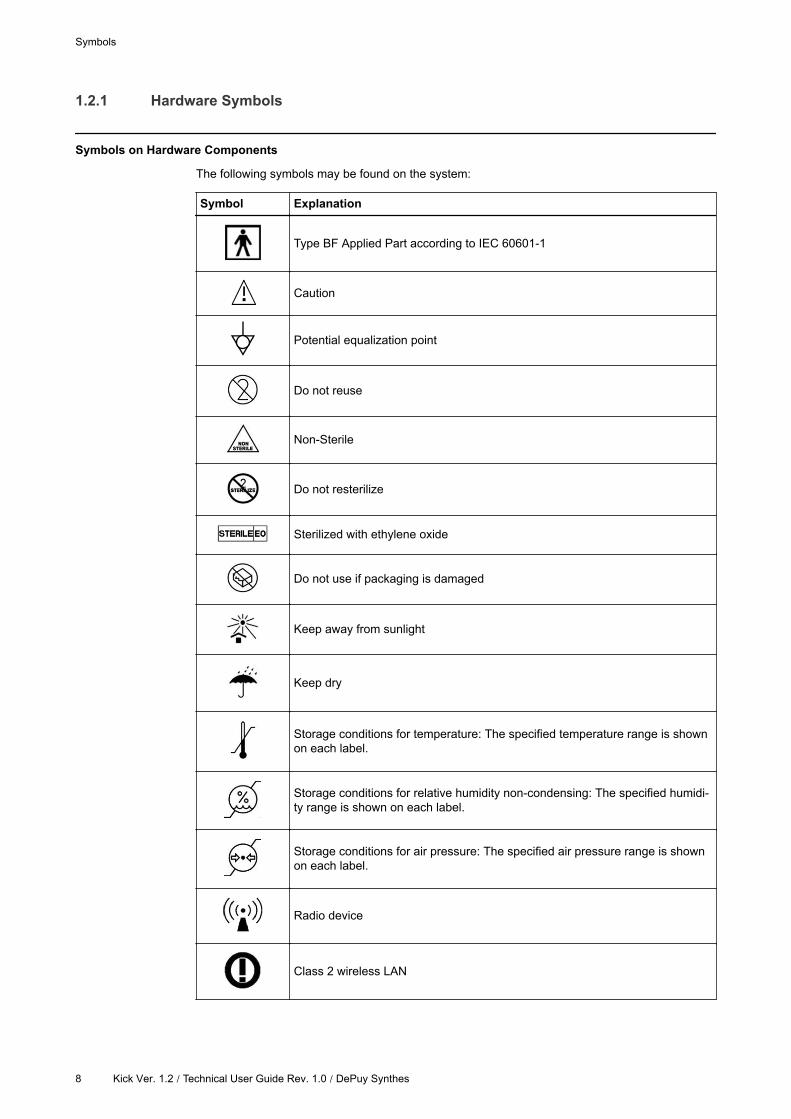
Symbols on Hardware Components
The following symbols may be found on the system:
Symbol Explanation
Type BF Applied Part according to IEC 60601-1
Caution
Potential equalization point
Do not reuse
Non-Sterile
Do not resterilize
Sterilized with ethylene oxide
Do not use if packaging is damaged
Keep away from sunlight
Keep dry
Storage conditions for temperature: The specified temperature range is shown
on each label.
Storage conditions for relative humidity non-condensing: The specified humidi-
ty range is shown on each label.
Storage conditions for air pressure: The specified air pressure range is shown
on each label.
Radio device
Class 2 wireless LAN
Symbols
8 Kick Ver. 1.2 / Technical User Guide Rev. 1.0 / DePuy Synthes

Symbol Explanation
Quantity of products in packaging
Batch number
Serial Number
Article number
Use by month YYYY
Date of manufacture
Manufacturer
Authorized representative in the European Community
IPXY
Ingress Protection according to IEC 60529
• X = Protection against ingress of solid objects
• Y = Protection against ingress of liquid
Strong magnetic field
Danger of clamping hand or other body parts in equipment
Do not look directly into the laser beam or point laser beam into the patient’s
face or eyes
Laser radiation emitted from aperture
Do not stare into beam
Class 2 laser product
max. output 1mW wavelength 635 nm
Danger of tilting: Do not move system when brakes are locked or if device is
blocked by obstacles
Standby icon
Consult the operating instructions
GENERAL INFORMATION
Kick Ver. 1.2 / Technical User Guide Rev. 1.0 / DePuy Synthes 9
Symbol Explanation
Consult accompanying documentation
Symbols
10 Kick Ver. 1.2 / Technical User Guide Rev. 1.0 / DePuy Synthes

1.3 Intended Use
Using the System
Intended System Use
The Kick system is a navigation platform used for Image Guided Surgery (IGS) incorporating:
• A tracking system
• A computer unit that runs the software
• A display unit to display the navigation, including touch functionality for the user to interact with
the software.
Technical Specifications
The technical specifications of Kick hardware components are subject to change due to technical
developments.
Careful Hardware Handling
Only trained medical personnel may operate system components and accessory
instrumentation.
System components and accessory instrumentation comprise precise mechanical parts.
Handle them carefully.
Changes to the System
Only use the system components as delivered by Brainlab. Do not modify the system in
any way. Altering the system or using it outside of its intended use may result in severe
harm to the patient, user or third-party.
MR Environment
The Kick system has not been tested in an MR environment.
Plausibility Review
Before patient treatment, review the plausibility of all information input to and output from
the system.
ME Systems
Additional equipment connected to medical electrical equipment must comply with the
respective IEC or ISO standards (e.g., IEC 60950 for data processing equipment and IEC
60601-1 for medical equipment). Furthermore, all configurations shall comply with the
requirements for medical electrical systems (see IEC 60601-1-1 or clause 16 of the 3rd
edition of IEC 60601-1, respectively). Anyone connecting additional equipment to the Kick
System configures a medical system and is therefore responsible that the system complies
with the requirements for medical electrical systems. Please note that local laws take
priority over the above-mentioned requirements. In doubt, consult your local
representative or the technical service department.
GENERAL INFORMATION
Kick Ver. 1.2 / Technical User Guide Rev. 1.0 / DePuy Synthes 11

NOTE: Unless otherwise specified, the use of multiple socket outlet(s) is not permitted.
Intended Use
12 Kick Ver. 1.2 / Technical User Guide Rev. 1.0 / DePuy Synthes

1.4 Training and Documentation
Brainlab Training
To ensure safe and appropriate use, before using the system all users should participate in a
training program held by a Brainlab authorized representative.
Supervised Support
Before using the system for surgical procedures where computer-aided navigation is considered
critical, perform a sufficient number of complete procedures with a Brainlab authorized
representative present to provide guidance where necessary.
Responsibility
This system solely provides assistance to the surgeon and does not substitute or replace
the surgeon’s experience and/or responsibility during its use.
GENERAL INFORMATION
Kick Ver. 1.2 / Technical User Guide Rev. 1.0 / DePuy Synthes 13

1.4.1 Documentation
Intended Audience
This user guide is intended for surgeons and hospital staff.
Relevant System Configurations
The information in this guide is relevant for the system configurations below:
System Configuration Art.-No. Device Art.-No.
Kick Navigation Station 18080Monitor Cart 18081
Camera Cart 18082
NOTE: All device article numbers are listed on the system plates on the back side of the Monitor
Cart.
Reading User Guides
The user guides describe complex medical devices and surgical navigation software that must be
used with care.
It is important that all users of the system, instruments and software:
• Read the user guides carefully before handling the equipment
• Have access to the user guides at all times
Disregarding information in the user guides, in particular the disregard of warning and cautions, is
considered to be abnormal use.
How to Use This Guide
The information provided in this guide will help you to determine whether your navigation system
is functioning properly.
Use this guide, in combination with assistance from Brainlab authorized support, to identify and
troubleshoot possible problems.
Do not attempt to service your system. Contact your Brainlab authorized support
representative for questions regarding repair and service.
Available User Guides
User Guide Contents
Software User Guides
• Overview of treatment planning and image-guided navigation
• Description of OR system setup
• Detailed software instructions
Instrument User Guides Detailed instructions on instrument handling
Cleaning, Disinfection and
Sterilization Guide
Detailed instructions on cleaning, disinfecting and sterilizing in-
struments
System User Guides Comprehensive information on system setup
Technical User GuideDetailed technical information on the system, including specifica-
tions and compliances
NOTE: Not all above-mentioned user guides are available or relevant for all Brainlab products.
Training and Documentation
14 Kick Ver. 1.2 / Technical User Guide Rev. 1.0 / DePuy Synthes

2 SYSTEM OVERVIEW
2.1 System Components
General Information
Kick is a touchscreen-operated planning and navigation system designed for pre- and
intraoperative use. All system components are suitable for continuous use during surgical
procedures.
The Kick system is a navigation platform used for image guided surgery, consisting of:
• A tracking system
• A computer unit that runs the software
• A display unit to display the navigation, including touch functionality for the user to interact with
the software
Optical Tracking
Optical tracking is achieved by a camera unit that emits and detects flashes of infrared light.
• Reflective elements, affixed to reference arrays on the patient and to instrumentation, reflect
the infrared signals back to the camera unit.
• Reflected signals from the reflective marker spheres and discs are captured and digitized by
each camera lens from a different angle.
• The software uses the camera input to calculate the relative three-dimensional positions of the
instruments and the patient reference arrays.
Electromagnetic Compatibility
Special precautions regarding electromagnetic compatibility (EMC) must be installed and put into
service according to the EMC information provided in this guide and the System User Guide.
SYSTEM OVERVIEW
Kick Ver. 1.2 / Technical User Guide Rev. 1.0 / DePuy Synthes 15

Components
Figure 1
No. Component
Telescopic camera post
Camera
Camera Cart
Monitor Cart
Touchscreen
Monitor post
System Components
16 Kick Ver. 1.2 / Technical User Guide Rev. 1.0 / DePuy Synthes

2.2 Monitor Cart
Monitor Cart Components
Figure 2
No. Component
Wheels
• Monitor Cart handle
• Monitor release trigger (back side of handle, not visible)
Monitor hinge
Touchscreen
Monitor cable
Cable hooks
On/off button
Monitor Cart base, containing:
• Medical computer unit
• Connection panel
SYSTEM OVERVIEW
Kick Ver. 1.2 / Technical User Guide Rev. 1.0 / DePuy Synthes 17

Monitor Components
Figure 3
No. Component
Monitor release trigger (back side of monitor handle)
Home button
NOTE: The function of this button may vary depending on the software application. See
relevant Software User Guide for more information.
USB ports (top of monitor, covered by flap)
Monitor Cart
18 Kick Ver. 1.2 / Technical User Guide Rev. 1.0 / DePuy Synthes

2.2.1 3rd-Party Connections
General Information
The 3rd-party equipment connections are located on the connection panel.
When connecting 3rd-party devices, adhere to the applicable regulations in IEC 60601-1-1,
specifically clause 16 of the 3rd edition of IEC 60601-1.
Connection Panel
Figure 4
No. Component
Mains power
Potential equalization
S-Video In
Video In
Hospital Network
Intraoperative data
USB
Tracking unit (Camera Cart)
Kolibri upgrade camera connection (covered in image)
Microscope and Video Out
NOTE: The unused tracking unit port is covered. If your tracking unit port requirements change,
contact Brainlab support.
WLAN Transmitter
The WLAN transmitter hardware deactivated in this version, but can be reactivated by service:
• The WLAN transmitter uses a frequency band for sending and receiving between 2.400 and
2.485 GHz with 19.8 Bm effective isotropic radiated power (EIRP).
SYSTEM OVERVIEW
Kick Ver. 1.2 / Technical User Guide Rev. 1.0 / DePuy Synthes 19

• The device is configured to use channel 1 to 11 (each with a channel space of 22 MHz). This
setting matches the regulatory requirements for USA, Canada, Japan, Europe, Australia, Hong
Kong and New Zealand. Contact Brainlab support or an authorized partner in case of
questions.
• The characteristic of modulation is DSSS for 802.11b,g or OFDM for 802.11n.
Monitor Cart
20 Kick Ver. 1.2 / Technical User Guide Rev. 1.0 / DePuy Synthes

2.2.2 LAN Connection
LAN Ports
The LAN ports support:
• 10 Mbps, 100 Mbps, and 1000 Mbps connections
• Automatic MDI/MDI-X configurations
Figure 5
LED Status Indication
ACT/LINK LED
Off No link
Solid orange Linked
Flashing orange Data activity
Speed LED
Off 10 Mbps connection
Orange 100 Mbps connection
Green 1 Gbps connection
Network Connection
Kick interfaces provide no means of separation according to IEC 60601-1:2005. It is
recommended to use an adequate separation device for the network (LAN) interface with a
rating of minimum 1 MOOP and a dielectric strength of minimum 1.5 kV.
Connecting Kick to a hospital network may create an ME system according to IEC
60601-1:2005. Ensure that hospital network components are compliant to the relevant IEC
standard.
SYSTEM OVERVIEW
Kick Ver. 1.2 / Technical User Guide Rev. 1.0 / DePuy Synthes 21
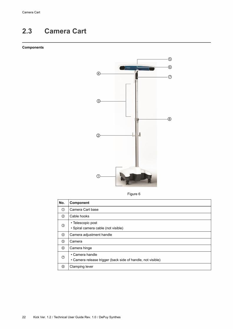
2.3 Camera Cart
Components
Figure 6
No. Component
Camera Cart base
Cable hooks
• Telescopic post
• Spiral camera cable (not visible)
Camera adjustment handle
Camera
Camera hinge
• Camera handle
• Camera release trigger (back side of handle, not visible)
Clamping lever
Camera Cart
22 Kick Ver. 1.2 / Technical User Guide Rev. 1.0 / DePuy Synthes

Camera Components
Figure 7
No. Component
Camera release trigger
Camera handle
Positioning laser
Lens
Illuminator filter
Camera adjustment handle
Laser trigger
Power Specifications
Specification Value
Voltage 18-32 Vdc
Power consumption 13.5 W
SYSTEM OVERVIEW
Kick Ver. 1.2 / Technical User Guide Rev. 1.0 / DePuy Synthes 23

Positioning Laser Specifications
The camera contains a Class II positioning laser .
Specification Value
Wavelength 635 nm
Maximum output 1 mW
Conforms to standards
• ANSI Z136.1 (2007)
• IEC 60825-1 (2007)
• FDA/CDRH 21 CFR 1040.10 and 1040.11 (except for deviations
pursuant to Laser Notice No. 50, dated June 24, 2007)
Camera Cart
24 Kick Ver. 1.2 | Technical User Guide Rev. 1.0 / DePuy Synthes

2.3.1 Camera Volume
Illustration
The camera field of view is a pyramid-shaped volume with the following dimensions:
Figure 8
No. View
Behind camera
Side
Top
How to Test the Camera Volume
Steps
1. Place an instrument with attached reflective marker spheres in the camera field of view.
2. Adjust the camera horizontally.
3. Measure the working distance.
4.
Measure the volume diameter at several distances.
NOTE: If the camera field of view is significantly decreased, the camera may need to be
repaired or exchanged.
NOTE: You can also check the camera field of view in the software as described in the Software
User Guides.
Tracking Unit Accuracy
To ensure the specified accuracy of the camera, adhere to the storage and operating
conditions (see page 44).
SYSTEM OVERVIEW
Kick Ver. 1.2 / Technical User Guide Rev. 1.0 / DePuy Synthes 25

Camera Cart
26 Kick Ver. 1.2 | Technical User Guide Rev. 1.0 / DePuy Synthes

3 TROUBLESHOOTING
3.1 Introduction
Chapter Information
The purpose of this chapter is to provide you with specific information in order to recognize
possible problems and communicate them to your Brainlab support representative.
Repair and Service
Do not attempt to service your system. Contact Brainlab authorized support for questions
regarding repair and service.
TROUBLESHOOTING
Kick Ver. 1.2 / Technical User Guide Rev. 1.0 / DePuy Synthes 27

3.2 Troubleshooting: Monitor Cart
Possible Occurrences
Power to the Monitor Cart
Occurance Possible Cause
No power to Monitor CartCheck that the mains power cabling is correctly
connected to power supply.
Touchscreen Display
There are two main functional monitor parts that affect the display:
• The display itself
• The backlight
Occurance Possible Cause
Some pixels (from which the displayed images
are constructed) may fail over time.The display may need to be replaced.
Touchscreen Functionality
Occurance Possible Cause
No touch functionality.
• The touch controller not functioning, or
• The driver that controls the mouse cursor not
functioning.
Cursor position on the screen does not corre-
spond to the part of the screen touched.
Calibration of the cursor has been lost. Contact
Brainlab support.
Troubleshooting: Monitor Cart
28 Kick Ver. 1.2 / Technical User Guide Rev. 1.0 / DePuy Synthes

3.3 Troubleshooting: Camera Cart
Possible Occurrences
Camera Occurrences
There are several possible occurrences that can be attributed to communication failures related to
the IR camera.
Occurance Symptoms Possible Causes
Decrease in cam-
era volume
• Restricted field of view
for navigation.
• LEDs in camera lens are
not on.
• Overheating
• Ageing of camera
• IR light from another device causing interfer-
ence (e.g., pulse oximeter).
• Surfaces in the OR are unintentionally re-
flecting IR light (e.g., reflective strips on
clothing).
No powerCamera does not beep
during boot-up.
• Problem with cabling
• Problem with electronics
No communicationCamera does not beep
during application start up.
• Communication error between Monitor and
Camera Carts: Check cabling
• Incorrect software configuration
Not tracking mark-
er spheres proper-
ly
Software displays uniden-
tifiable gray marker
spheres in the camera
field of view.
• IR light from another device causing interfer-
ence (e.g., pulse oximeter).
• Surfaces in the OR are unintentionally re-
flecting IR light (e.g., reflective strips on
clothing).
NOTE: If you are having problems with your camera, contact Brainlab authorized support.
TROUBLESHOOTING
Kick Ver. 1.2 / Technical User Guide Rev. 1.0 / DePuy Synthes 29

Troubleshooting: Camera Cart
30 Kick Ver. 1.2 | Technical User Guide Rev. 1.0 / DePuy Synthes

4 ELECTRICAL SAFETY
4.1 Classification
Monitor Cart and Camera Cart
The Monitor Cart and the Camera Cart are classified as Class I Equipment according to IEC
60601-1 and must be tested accordingly.
Classification Definition
Class I
Refers to equipment classification regarding protection against electric shock.
Protective means are provided for metallic accessible parts or metallic internal
parts, such as connection to PE (protective earth).
Safety Requirements
To avoid the risk of electrical shock, the Monitor Cart must only be connected to a mains
power supply with protective earth.
ELECTRICAL SAFETY
Kick Ver. 1.2 / Technical User Guide Rev. 1.0 / DePuy Synthes 31

4.2 Test Requirements
Interval
The recurrent test should be performed once annually or if the equipment is repaired or modified.
The test is mandatory for medical electrical equipment and when creating a medical electrical
system according to IEC 60601-1-1 or clause 16 of the 3rd edition of IEC 60601-1, respectively.
Repeat this test any time the medical electrical equipment or medical electrical system setup is
changed, e.g., after repair of one or all combined equipment or after the exchange of equipment
components like cables.
For sustained safety of the equipment, a yearly electrical safety test according to IEC 62353
is required. For an ME SYSTEM or permanently installed equipment, an electrical safety
test according to IEC 60601-1 may be required.
NOTE: Local regulations, national deviations and requirements that vary from these standards
take precedent.
Scope
The test must include all the items as specified starting on page 33.
Each individual equipment of the ME SYSTEM that has its own connection to supply mains, or
which can be connected/disconnected from mains supply without the use of a tool, must be tested
individually. Additionally, the ME SYSTEM must be tested as a whole to avoid that an aging
component causes unacceptable values.
If items of ME EQUIPMENT that are combined into an ME SYSTEM by functional connections
cannot be tested separately for technical reasons, test the complete ME SYSTEM.
In addition, Brainlab support or authorized partners shall regularly clean air intake filters and
exchange the battery when necessary.
Inspections by Non-Brainlab Personnel
Only qualified, trained and skilled personnel are allowed to perform electrical safety tests.
Qualification shall include training on the subject, test equipment, knowledge, experience
and acquaintance with the relevant technologies, standards and local regulations.
Personnel assessing the safety must be able to recognize possible consequences and
risks arising from non-conforming equipment.
Brainlab must be informed immediately in writing if equipment is deemed unsafe.
Inspections by Brainlab Authorized Support
• If a suitably qualified person is not available at the customer site, Brainlab support will perform
this inspection for a set fee.
• Brainlab performs an inspection at the end of the warranty at no charge.
• If you require a Brainlab support specialist, contact Brainlab support.
Test Requirements
32 Kick Ver. 1.2 | Technical User Guide Rev. 1.0 / DePuy Synthes

4.2.1 Testing Overview
Testing Precautions
ME SYSTEM test steps must be performed as described below.
• The described test only covers the Brainlab Kick equipment and not connected equipment.
• In addition, follow the directions given by the manufacturer of the connected device.
• During measurement, all devices must be in operation mode.
• Perform tests in normal condition as well as in single fault condition.
Visually inspect the ME SYSTEM to determine whether the configuration is still the same as
at the time of the last inspection, or whether units of the ME SYSTEM have been
exchanged, added or removed. Such changes must be documented, as well as any
changes to the configuration of ME SYSTEM. Any changes void the validity of previous
reference values.
Test Guidelines
When performing recurrent tests:
• Perform required test steps in the order defined below.
• All tests must be passed before the device can be considered safe.
• The calibration of the measuring device must be valid at the time of measurement.
• Measurement results measured after changes of the ME SYSTEM shall be documented as
reference values.
If a test does not pass, device must be repaired by Brainlab support.
Required Test Steps for ME EQUIPMENT
Steps
1. Visual inspection
2. Protective earth resistance
3. Equipment leakage current
4. Insulation resistance
5. Functional test
6. Report results
7. Evaluate results
8. Check and prepare for normal use
Required Test Steps for ME SYSTEMS
Steps
1.
Test each piece of equipment of the ME SYSTEM individually, according to steps 1-4 for
ME EQUIPMENT.
Report and evaluate these results.
2. Touch current
3. Functional test
4. Report results
ELECTRICAL SAFETY
Kick Ver. 1.2 / Technical User Guide Rev. 1.0 / DePuy Synthes 33

Steps
5. Evaluate results
6. Check and prepare for normal use
Test Report Form
• Use the test report form (from page 41) to enter the inspection results.
• Keep form as a record of the inspection.
Test Requirements
34 Kick Ver. 1.2 / Technical User Guide Rev. 1.0 / DePuy Synthes

4.2.2 Recurrent Tests
Test Steps to Be Performed
IEC 62353 is the basis for measurement requirements, conditions and setup.
Step Instructions and Conditions
Visual inspection
Prepare device for normal use. Use original power supply cord provided
by Brainlab.
Check all relevant cables for dents, damaged insulation and blank lines.
Move and bend the cables around your hand to slightly stretch the insula-
tion. Any visible damage is not acceptable.
Check Kick for visible damage, broken cables and blank lines. With the
exception of air vents, you should not be able to see the interior of the de-
vice. Damaged cables, blank lines or visibility of the interior are not ac-
ceptable.
Check indicator LEDs for detected errors.
If any damages are detected, place the device out of operation, mark as
such and contact Brainlab support.
Protective earth re-
sistance ( Monitor
Cart only)
Definition:
Resistance between any accessible conductive part that must, for safety
purposes, be connected to the protective earth terminal and one of the
following:
• Protective connector of the mains plug
• Protective connector of the appliance inlet, or
• Protective conductor permanently connected to the mains supply
Resistance between protective connectors at each end of a detachable
power supply cord.
Prepare device for normal use.
Measure the protective earth resistance for all measurement points indi-
cated starting on page 37.
Equipment leakage
current
Definition:
Current flowing from mains parts to earth via the protective earth conduc-
tor and accessible conductive parts of the enclosure and applied parts.
Prepare device for normal use.
If you are using an electrical safety test device, connect the Monitor Cart
to the device when testing a Kick system.
Measure the earth leakage current for all measurement points indicated
starting on page 38.
Touch current (Re-
quired for ME SYS-
TEM)
Definition:
Leakage current flowing from the enclosure or from parts thereof, exclud-
ing patient connections, accessible to any operator or patient in normal
use, through an external path other than the protective earth conductor, to
earth or to another part of the enclosure.
Prepare device for normal use.
If you are using an electrical safety test device, connect the Monitor Cart
to the device when testing a Kick system.
Connect the required functional connections to create the medical electri-
cal system and switch devices on.
Measure the touch current for all measurement points indicated starting
on page 38.
ELECTRICAL SAFETY
Kick Ver. 1.2 | Technical User Guide Rev. 1.0 / DePuy Synthes 35

Step Instructions and Conditions
Patient leakage cur-
rent
Definition:
• Leakage current flowing from the patient connections via the patient to
earth, or
• Originating from the unintended appearance of a voltage from an exter-
nal source on the patient and flowing from the patient via the patient
connections of an F-TYPE applied part to earth.
Prepare device for normal use.
Select a non-conductive surface to position the applied part.
Measure the patient leakage current as indicated on page 33.
Insulation resistance
Definition:
For Class I electrical equipment resistance of insulating material is meas-
ured at the mains supply between the live and neutral pins connected to-
gether and the protective earth pin.
Prepare device for normal use.
If you are using an electrical safety test device, connect the Monitor Cart
to the device when testing.
Measure the insulation resistance between the connected mains supply
line/neutral (L/N) and the protective earth (PE).
Functional test
Prepare device for normal use.
Power on the device.
Check that indicator LEDs do not show errors. Check for system alarms.
NOTE: For detailed information on indicator LEDs and system alarms,
see the System User Guide.
Before starting surgery, start the system, ensuring that it boots up correct-
ly and patient data is correctly loaded in the navigation application.
Report results Generate a test report.
Evaluate results Determine whether the device is safe and effective.
Check and prepare
for normal use
After testing, check that the device is restored to the conditions necessary
for normal use before being returned into service.
Remove all devices that have been connected, e.g., measurement device
with probes and lines.
Acceptable Values
Values are limited according to the standards.
Test Step Standard
Protective earth resistance
IEC 62353Equipment leakage current
Insulation resistance
Patient leakage current
Touch current IEC 60601-1
Measured Values
Required measurement points are listed starting on page 37.
A sample test report form is available starting from page 41.
Test Requirements
36 Kick Ver. 1.2 / Technical User Guide Rev. 1.0 / DePuy Synthes
4.3 Performing Tests
Protective Earth Resistance
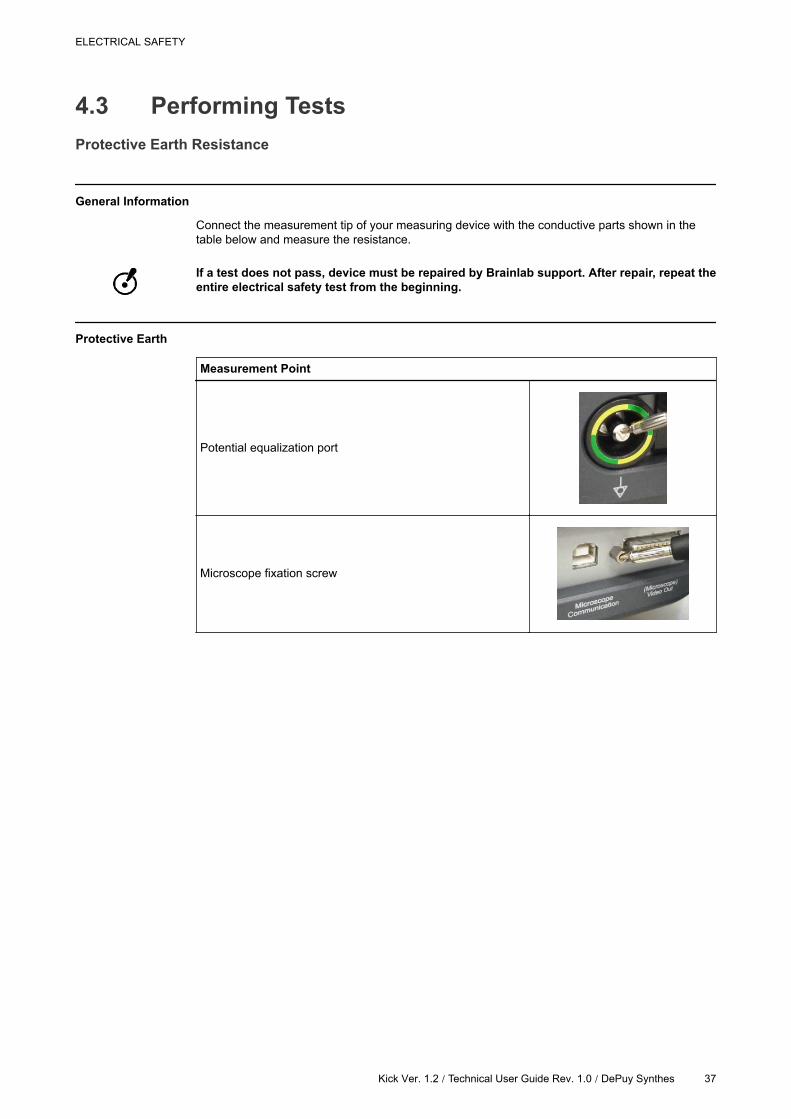
General Information
Connect the measurement tip of your measuring device with the conductive parts shown in the
table below and measure the resistance.
If a test does not pass, device must be repaired by Brainlab support. After repair, repeat the
entire electrical safety test from the beginning.
Protective Earth
Measurement Point
Potential equalization port
Microscope fixation screw
ELECTRICAL SAFETY
Kick Ver. 1.2 / Technical User Guide Rev. 1.0 / DePuy Synthes 37

4.3.1 Leakage Current
General Information
Connect the measurement tip of your measuring device with the conductive parts shown in the
table and measure the leakage current.
Equipment Leakage Current
Measurement Point
Monitor fixation screw
Monitor cart base
Camera plug at connection panel
Screw on camera hinge
Camera cart base
Performing Tests
38 Kick Ver. 1.2 | Technical User Guide Rev. 1.0 / DePuy Synthes
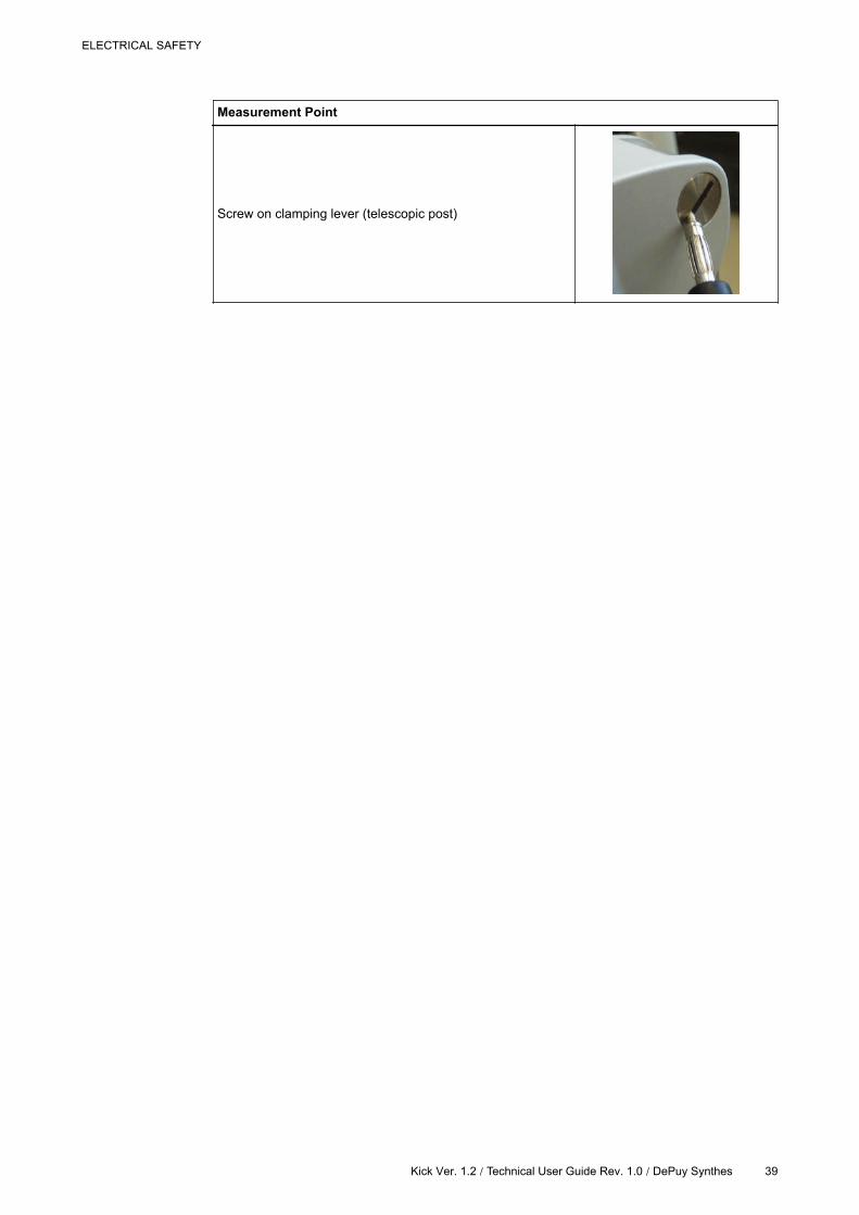
Measurement Point
Screw on clamping lever (telescopic post)
ELECTRICAL SAFETY
Kick Ver. 1.2 / Technical User Guide Rev. 1.0 / DePuy Synthes 39

4.3.2 Insulation Resistance
General Information
Connect the device to your measurement device and measure the insulation resistance.
Performing Tests
40 Kick Ver. 1.2 / Technical User Guide Rev. 1.0 / DePuy Synthes

4.4 Test Report
Test Report Form
Below is an example of test documentation with minimum specifications.
Testing organization:
Tester name:
Test before putting into service (reference val-
ue):
Recurrent test:
Test after repair:
Responsible organization:
Equipment/device tested: ID-Number:
Type: Serial number:
Manufacturer: Class of protection:Class I Class II Battery
Applied part type:
N/A
B
BF
CF
Mains connection:
Permanently installed equipment
Non-detachable power supply
cord
Detachable power supply cord
Equipment type:
ME EQUIPMENT
ME SYSTEM
Accessories:
Test
Measurement equipment (model, ID, calibration date):
Test passed?
Yes/No
Visual inspection
Measurements:Measured value Test passed?
Yes/NoNC SFC
Protective earth resistance - mΩ
Equipment leakage current - al-
ternative methodμA
Equipment leakage current - di-
rect methodμA
Equipment leakage current - dif-
ferential methodμA
Touch current (ME SYSTEM) μA
Patient leakage current (applied
parts) - alternative methodμA
Patient leakage current (mains
on applied parts) - direct meth-
od
μA
Insulation resistance - MΩ
Other
Functional test (parameters tested):
Device has been checked and is prepared for normal use
ELECTRICAL SAFETY
Kick Ver. 1.2 / Technical User Guide Rev. 1.0 / DePuy Synthes 41

Deficiency/Notes:
Overall assessment:
No safety or functional deficiencies were detected.
No direct risk, deficiencies detected may be corrected on short term.
Equipment shall be taken out of operation until deficiencies are corrected.
Equipment does not comply: Modification/exchange of components/taking out of service is
recommended.
Next recurrent test necessary in __
months:
6 12 24 36
Name: _________________________ Date / Signature: ______________________________
Test Report
42 Kick Ver. 1.2 | Technical User Guide Rev. 1.0 / DePuy Synthes

5 COMPLIANCES AND
SPECIFICATIONS
5.1 Electrical Standards
Certificates and Approvals
Certificate/Approval
Certificates
IEC 60601-1
ANSI/AAMI ES60601-1
EN60601-1
IEC 60529 IP20
Power Specifications - North America
In North America: if the unit is connected to 240 V, only connect it to a center-tapped outlet
labeled 240 V power supply.
COMPLIANCES AND SPECIFICATIONS
Kick Ver. 1.2 / Technical User Guide Rev. 1.0 / DePuy Synthes 43

5.2 Environmental Requirements
Transport/Storage and Operating Conditions
Local Restrictions
• Store and operate systems in locations that are protected against moisture, wind, sunlight,
dust, salinity and sulfur.
• Do not store systems in the close vicinity of chemical products or gas.
• Do not expose systems to direct UV light.
Altitude Considerations
• Unless stated otherwise, the system is rated for use at an altitude < 3000 meters.
• Transport or store the system at an altitude < 6000 meters.
Adaption Time
Adaption time for use after extreme storage conditions is a minimum of one hour.
Environmental Conditions - Kick
The following environmental requirements apply for the Kick system:
Specification Operating Conditions
Temperature 10°C (50°F) to 35°C (95°F)
Humidity 30% to 75% non-condensing
Pressure 700 hPa to 1060 hPa
Specification Transport/Storage Conditions
Temperature-10°C (14°F) to 45°C (113°F) (for a period of time not exceeding 15
weeks)
Humidity 10% to 90% non-condensing
Pressure 500 hPa to 1060 hPa
NOTE: Transport/storage values are valid for the system when contained in the transport cases.
Environmental Requirements
44 Kick Ver. 1.2 / Technical User Guide Rev. 1.0 / DePuy Synthes

5.3 System Specifications
Physical Characteristics
Monitor Only
Specification Value
Height 328 mm
Width 540 mm
Depth 75 mm
Weight 6.7 kg
Monitor Angle Flexibility See System User Guide.
NOTE: These values are based on the monitor without the protection cover.
Camera Only
Specification Value
Height 76 mm
Width 630 mm
Depth 115 mm
Weight 2.6 kg
NOTE: These values are based on the camera without the protection cover.
Complete Monitor Cart
Figure 9
COMPLIANCES AND SPECIFICATIONS
Kick Ver. 1.2 / Technical User Guide Rev. 1.0 / DePuy Synthes 45

Specification Value
Height 1550 mm
Footprint 500 x 500 mm
Weight 25.5 kg
Complete Camera Cart
Figure 10
Specification Value
Max. Height 2350 mm
Min. Height 1450 mm
Footprint 500 x 500 mm
Weight 19 kg
System Specifications
46 Kick Ver. 1.2 | Technical User Guide Rev. 1.0 / DePuy Synthes

5.3.1 Technical Specifications
Monitor Cart and Medical Computer Unit
Specification Value
Electrical Specifications
AC input 100 VAC - 240 VAC
Frequency 50/60 Hz
Power consumption3 A @ 100 VAC
1.5 A @ 240 VAC
CMOS Battery 3V CR2032 Lithium Battery 210 mAh
Processor Intel Core i5-520E 2.40 GHz
RAM 4 GB
Supported I/O
• 6 USB 2.0
• Potential equalization
• Camera
• S-Video In
• 2 LAN 1 GBit/s
• CVBS
• DVI-I
Mass Storage Internal Hard Disk 2.5” 160 GB
Audio• 2 W
• Speaker volume: 60-65 dB(A)
Display 21.46”, FHD resolution
Touchscreen Resistive touchscreen
Camera Cart
Specification Value
Input Voltage 18-32 Vdc
Power Consumption 13.5 W
Tracking Accuracy 0.3 mm RMS (Root Mean Square)
COMPLIANCES AND SPECIFICATIONS
Kick Ver. 1.2 / Technical User Guide Rev. 1.0 / DePuy Synthes 47

5.4 Compliances
Electromagnetic Emissions
Electromagnetic Environment
Kick systems are intended for use in the electromagnetic environment specified in the table
below.
The user is responsible ensuring that the systems are used in such an environment.
Declaration
Guidance and manufacturer’s declaration regarding electromagnetic emissions:
Emissions Test Compliance Electromagnetic Environment - Guidance
RF emissions CISPR
11Group 1
The Kick system uses RF energy only for its internal
function. Therefore, its RF emissions are very low
and are not likely to cause any interference in nearby
electronic equipment.
RF emissions CISPR
11Class A
The Kick system is suitable for use in all establish-
ments other than domestic, and may be used in do-
mestic establishments and those directly connected
to the public low-voltage power supply network that
supplies buildings used for domestic purposes, pro-
vided the warnings in this user guide are heeded.
Harmonic emissions
IEC 61000-3-2Class A
Voltage fluctuations/
flicker emissions IEC
61000-3-3
Complies
The system should not be used adjacent to, or in direct contact with other equipment. If
this cannot be avoided, normal operation must be verified in the configuration in which it
will be used.
Compliances
48 Kick Ver. 1.2 / Technical User Guide Rev. 1.0 / DePuy Synthes

5.4.1 General Electromagnetic Immunity
Electromagnetic Environment
Kick systems are intended for use in the electromagnetic environment specified in the following
sections.
The user is responsible ensuring that the systems are used in such an environment.
Electromagnetic Immunity Declaration
The tables in the following sections provide guidance according to the manufacturer’s
electromagnetic immunity declaration.
COMPLIANCES AND SPECIFICATIONS
Kick Ver. 1.2 | Technical User Guide Rev. 1.0 / DePuy Synthes 49

5.4.2 Electromagnetic Immunity, Kick System
IEC 61000-4-2, IEC 61000-4-4, IEC 61000-4-5, IEC 61000-4-8, IEC 61000-4-11
Immunity Test IEC 60601 Test Level and
Compliance Level
Electromagnetic Environment - Guidance
Electrostatic dis-
charge (ESD) IEC
61000-4-2
± 6 kV contact
± 8 kV air
Floors should be wood, concrete or ceramic
tile. If floors are covered with synthetic mate-
rial, the relative humidity should be at least
30%.
Electrical fast tran-
sient/burst IEC
61000-4-4
± 2 kV for power supply
lines
± 1 kV for input/output lines
Mains power quality should be that of a typi-
cal commercial or hospital environment.
Surge IEC
61000-4-5
± 1 kV line(s) to line(s)
± 2 kV line(s) to earth
Mains power quality should be that of a typi-
cal commercial or hospital environment.
Voltage dips, short
interruptions and
voltage variations
on power supply in-
put lines IEC
61000-4-11
<5% UT (>95% dip in UT)
for 0.5 cycle
40% UT (60% dip in UT) for
5 cycles
70% UT (30% dip in UT) for
25 cycles
<5% UT (>95% dip in UT)
for 5 s
Mains power quality should be that of a typi-
cal commercial or hospital environment. If the
Kick system user requires continued opera-
tion during power mains interruptions, it is
recommended that the Kick system be pow-
ered from an uninterruptible power supply or
a battery.
Power frequency
(50/60 Hz) magnet-
ic field IEC
61000-4-8
3 A/m
Power frequency magnetic fields should be
at levels characteristic of a typical location in
a typical commercial or hospital environment.
NOTE: UTis the AC mains voltage prior to application of the test level.
IEC 61000-4-6, IEC 61000-4-3
Immunity
Test
IEC 60601
Test Level
Compliance
Level
Electromagnetic Environment - Guidance
Conducted
RF IEC
61000-4-6-
3 Vrms 150
kHz to 80
MHz
3 V
Portable and mobile RF communications equip-
ment should be used no closer to any part of the
Kick system, including cables, than the recom-
mended separation distance calculated from the
equation applicable to the frequency of the
transmitter.
Recommended separation distance:
d 1 2 P,=
d 1 2 P,= 80 MHz to 800 MHz
d 2 3 P,= 800 MHz to 2.5 GHz
Compliances
50 Kick Ver. 1.2 / Technical User Guide Rev. 1.0 / DePuy Synthes

Immunity
Test
IEC 60601
Test Level
Compliance
Level
Electromagnetic Environment - Guidance
Radiated RF
IEC
61000-4-3
3 V/m 80
MHz to 2.5
GHz
3 V/m
Where P is the maximum output power rating of
the transmitter in watts (W) according to the
transmitter manufacturer and d is the recom-
mended separation distance in meters (m).
Field strengths from fixed RF transmitters, as
determined by an electromagnetic site surveya
should be less than the compliance levelb in
each frequency range.
Interference may occur in the vicinity of equip-
ment marked with this symbol:
NOTE: At 80 MHz and 800 MHz, the higher frequency range applies.
NOTE: These guidelines may not apply in all situations. Electromagnetic propagation is affected
by absorption and reflection from structures, objects and people.
a Field strengths from fixed transmitters, such as base stations for radio (cellular/cordless) tele-
phones and land mobile radios, amateur radio, AM and FM radio broadcast and TV broadcast
cannot be predicted theoretically with accuracy. To assess the electromagnetic environment due
to fixed RF transmitters, an electromagnetic site survey should be considered. If the measured
field strength in the location in which the Kick system is used exceeds the applicable RF compli-
ance level above, the Kick system should be observed to verify normal operation. If abnormal
performance is observed, additional measures may be necessary, such as re-orienting or relo-
cating the Kick system.
b Over the frequency range 150 kHz to 80 MHz, field strengths should be less than 3 V/m.
COMPLIANCES AND SPECIFICATIONS
Kick Ver. 1.2 | Technical User Guide Rev. 1.0 / DePuy Synthes 51

5.4.3 RF Communications Equipment
Electromagetic Environment
Portable and mobile RF communications equipment can affect the systems.
The Kick system is intended for use in an electromagnetic environment in which radiated RF
disturbances are controlled.
The Kick system user can help prevent electromagnetic interference by maintaining a minimum
distance between portable and mobile RF communications equipment (transmitters) and the Kick
system as recommended below, according to the maximum output power of the communications
equipment.
Separation Distances
Recommended separation distances between portable and mobile RF communications equipment
and the Kick system:
Rated Maximum Out-
put Power of Trans-
mitter (W)
Separation Distance According to Frequency of Transmitter (m)
150 kHz to 80 MHz
d 1 2 P,=
80 MHz to 800 MHz
d 1 2 P,=
800 MHz to 2.5 GHz
d 2 3 P,=
0.01 0.12 0.12 0.23
0.1 0.37 0.37 0.74
1 1.2 1.2 2.3
10 3.7 3.7 7.4
100 12 12 23
For transmitters rated at a maximum output power not listed above, the recommended separa-
tion distance d in meters (m) can be determined using the equation applicable to the frequency
of the transmitter, where P is the maximum output power rating of the transmitter in watts (W)
according to the transmitter manufacturer.
NOTE: At 80 MHz and 800 MHz, the separation distance for the higher frequency range applies.
NOTE: These guidelines may not apply in all situations. Electromagnetic propagation is affected
by absorption and reflection from structures, objects and people.
Compliances
52 Kick Ver. 1.2 / Technical User Guide Rev. 1.0 / DePuy Synthes

5.4.4 Tested Cables
Use of Specified Cables
The use of accessories and cables other than those specified (with the exception of cables
sold by Brainlab as replacement parts), may result in increased emissions or decreased
immunity of the equipment.
Cable Specifications
Kick system cables that have been tested for emission and immunity conformity:
Cable Specification
Optical tracking unit cable Provided by Brainlab; 10 m long
Power cable Provided by Brainlab; 5 m long
Potential equalization cable Provided by Brainlab; 5 m long
S-Video 2 BNC coax cables, shielded, terminated, 75 Ohm; 30 m long
CVBS BNC coax cable, shielded, terminated, 75 Ohm; 30 m long
Hospital Network Provided by Brainlab; 5 m long
Intraoperative Data Provided by Brainlab; 5 m long
Microscope Provided by Brainlab; 10 m long
COMPLIANCES AND SPECIFICATIONS
Kick Ver. 1.2 / Technical User Guide Rev. 1.0 / DePuy Synthes 53

5.4.5 Hospital Network
General Information
Users must identify, analyze, evaluate and control the risks that may occur when connecting the
Kick system to a network or data coupling where other equipment is connected.
Wireless networks must comply with the definitions of the standard 802.11n.
Making changes to the network/data coupling could introduce new risks that require additional
analysis. These changes may include, but are not limited to:
• Changes in configuration
• Connection or disconnection of additional equipment
• Update or upgrade of connected equipment
Network Information Flow
For patient data transfer, the Kick system receives data from the hospital network server (e.g.,
PACS server).
For remote access, streaming or session sharing, the Kick system sends data to a streaming
client inside the hospital network.
Hospital Network Requirements
Requirement Values
Bandwidth
• Minimum: 2 Mbit/s (e.g., for data transfer)
• Recommended: 10-50 Mbit/s (e.g., for streaming and remote access)
• Optimum: 100 Mbit/s - 1Gbit/s (e.g., for session sharing)
Latency
• Maximum: ≤ 100 ms
• Recommended: ≤ 25 ms
• Optimum: ≤ 2 ms
Safety
• Only connect equipment to a secured network
• Network protected against unwanted access (e.g., user authentication,
firewall, etc.)
• Network protected against malicious software
• Internet Protocol Suite (TCP/IP)
Network Precautions
Streaming the display content of the Kick system or using session sharing may create high
traffic load on the hospital network.
When integrating the Kick system to a wireless hospital network, select an adequate
encryption (WPA2 or better) to protect patient data from unauthorized access.
Potential Hazards of Network Failure
The following hazardous situations could result if the hospital network or data coupling does not
meet the requirements listed in this section:
• Patient treated incorrectly due to:
- Network failure during patient data transfer
- Malware (e.g., viruses) causing PC to miscalculate data
• Unwanted exposure of the patient to anesthetics or radiation due to network failure during
patient data transfer
Compliances
54 Kick Ver. 1.2 / Technical User Guide Rev. 1.0 / DePuy Synthes

5.5 Power Plugs
General Information
The Kick system comes equipped with a specific power plug suitable for the region of use.
Use of Specified Power Cords
Reliable grounding can only be achieved when the system is connected to an equivalent
receptacle marked “Hospital Only” (“Hospital Grade” in North America). Only insert the
main plug into a socket outlet that is protectively earthed. Do not negate the protective
action by the use of an extension cable.
COMPLIANCES AND SPECIFICATIONS
Kick Ver. 1.2 / Technical User Guide Rev. 1.0 / DePuy Synthes 55

5.5.1 Regional Power Plugs
Power Plugs (Examples)
Power Plug Region
EU
Switzerland
UK
US
Australia
South Africa
Power Plugs
56 Kick Ver. 1.2 / Technical User Guide Rev. 1.0 / DePuy Synthes

5.6 USB Flash Drives
General Information
You can use a USB flash drive to transfer patient data between Brainlab planning and navigation
stations.
Handling USB Flash Drives
When using a USB flash drive, keep the following points in mind:
• Do not directly touch the USB connector (metal part of the USB flash drive).
• After use, replace the cover on the USB flash drive.
USB flash drives are highly sensitive to electrostatic discharge. Handle them with care to
prevent damage to the device.
COMPLIANCES AND SPECIFICATIONS
Kick Ver. 1.2 | Technical User Guide Rev. 1.0 / DePuy Synthes 57

USB Flash Drives
58 Kick Ver. 1.2 / Technical User Guide Rev. 1.0 / DePuy Synthes

6 MAINTENANCE
6.1 Inspections
Expected Service Life
Brainlab provides a minimum of eight years of service for platforms. During this period of time,
spare parts as well as field support are offered.
The Kick system lifetime is dependent on factors such as method and duration of each use, and
handling between uses. Careful functional testing and inspection of the Kick system before use is
the best method for determining the end of lifetime.
The end of lifetime is normally determined by wear and tear damage due to use. As part of
preventive service, follow the maintenance instructions.
Ensuring Safety and Functionality
Do not carry out inspections or maintenance while Kick is being used for patient treatment.
The system should be maintained and inspected on a regular basis to ensure functionality
and safety.
Interval
A detailed inspection should be performed by Brainlab support once a year (see page 61).
Authorized Persons
Only Brainlab and/or authorized partners are allowed to service the system and equipment.
Risk of electrical shock: There are no user-serviceable parts. All servicing is to be carried
out by trained technicians or referred to Brainlab.
Before Using the System
If the system has not been used for an extended period of time, verify that everything operates
normally before beginning patient treatment.
MAINTENANCE
Kick Ver. 1.2 / Technical User Guide Rev. 1.0 / DePuy Synthes 59

6.1.1 Inspections
Weekly
Component Inspection
Cabling and connectors Visual control (look for damage, twists, cracks)
Cleaning Refer to the System User Guide
Monthly
Component Inspection
General components
• Inspect for physical damage
• Marking and type plates readable
• Function of connection to 3rd-party equipment (e.g., microscope)
Wheels and brakes
( Monitor Cart and Cam-
era Cart)
Functionality
Camera
• Functionality
• Visual inspection (wear and tear)
• Both lenses are clean and not scratched or otherwise damaged
Monitor Cart
• Functionality
• Stability of the monitor fixation and scratches on the touchscreen
• Standby button
• Power LED
• USB connection
• Network connection
Monitor Cart and Cam-
era CartCheck that there are no loose or missing screws.
Inspections
60 Kick Ver. 1.2 / Technical User Guide Rev. 1.0 / DePuy Synthes

6.1.2 Annual Inspection by Brainlab
Arrangement
• If you have a service contract, Brainlab automatically performs the annual inspection.
• If you do not have a service contract, contact Brainlab support to arrange the inspection.
Scope
This inspection covers all components and functions as well as the items specified on the safety
inspection form.
Annual Inspection Points
Component Inspection
Camera Cart
• Functional test of camera
• Functional test of camera handle
• Functional test of complete cart
• Check of mechanical support system (posts, wheels and locks)
Monitor Cart
• Functional test of device
• Check of mechanical support system (posts, wheels and locks)
• Air filter exchange
System • Electrical safety test (see page 31)
MAINTENANCE
Kick Ver. 1.2 / Technical User Guide Rev. 1.0 / DePuy Synthes 61

6.2 Air Filter Exchange
Authorization
Only Brainlab, authorized partners and trained hospital technicians are allowed to exchange the
air filter.
Exchange Interval
The Monitor Cart air filter must be exchanged annually. If you have a service contract, Brainlab
automatically performs air filter exchange.
If you do not have a service contract, contact Brainlab support to request a replacement air filter.
Replacement Filters
Only use replacement air filters that are provided by Brainlab.
Replacement filters come attached to the air vent cover, i.e., the entire air vent cover is replaced.
How to Exchange Air Filter
Figure 11
Steps
1. Push down on the vent clips to remove the air vent cover.
2. Replace with new air vent cover, ensuring the vent clips click into place.
Air Filter Exchange
62 Kick Ver. 1.2 / Technical User Guide Rev. 1.0 / DePuy Synthes

6.3 Damaged Equipment
Discontinue Use
If you discover a defect:
Steps
1. Switch the system off.
2. Disconnect the system from mains power by unplugging power cable.
3. Contact Brainlab authorized support.
4. Place a notice such as “DO NOT USE” on the equipment to prevent inadvertent use.
Do not continue to use equipment that has been found to be defective during an
inspection. Using damaged equipment may cause patient injury.
Required Information
When you contact Brainlab support regarding a defect, you are asked for:
• System serial number on the Monitor Cart type plate
• Component serial number inscribed on the component (Monitor, Camera Cart components)
• A description of the problem
Repair/Replacement
Brainlab support:
• Provides you with a cost estimate for repair or replacement
• Informs you when your system is expected to be operational again (usually within 48 hours)
Return Instructions
Refer to the System User Guide.
MAINTENANCE
Kick Ver. 1.2 / Technical User Guide Rev. 1.0 / DePuy Synthes 63

Damaged Equipment
64 Kick Ver. 1.2 / Technical User Guide Rev. 1.0 / DePuy Synthes

INDEXNumerics
3rd-party connections.................................................................19
A
annual inspection....................................................................... 61
C
cables......................................................................................... 53
camera field of view....................................................................25
camera volume...........................................................................25
CE label........................................................................................6
certificates.................................................................................. 43
connection panel........................................................................ 19
contact information....................................................................... 5
D
damaged equipment...................................................................63
dielectric strength....................................................................... 40
dimensions................................................................................. 45
documentation............................................................................14
E
electrical safety
inspection interval...................................................................32
test guidelines.........................................................................33
electromagnetic emissions......................................................... 48
electromagnetic environment..................................................... 48
electromagnetic immunity...........................................................50
equipment damage.....................................................................63
F
FCC Statement.............................................................................6
feedback.......................................................................................5
functional earth resistance......................................................... 37
G
guides.........................................................................................14
H
hospital network
hazards...................................................................................54
requirements...........................................................................54
I
inspections
annual.....................................................................................61
authorized persons................................................................. 59
interval.................................................................................... 59
monthly................................................................................... 60
weekly.....................................................................................60
L
laser
camera positioning................................................................. 24
M
manuals......................................................................................14
manufacturer................................................................................ 5
medical electrical system............................................................11
monthy inspections.....................................................................60
O
optical tracking system............................................................... 15
P
positioning laser......................................................................... 24
power plugs................................................................................ 55
regional...................................................................................56
protective earth resistance......................................................... 37
R
recurrent test
guidelines............................................................................... 33
requirements...........................................................................32
revision numbers........................................................................ 11
RF communications equipment..................................................52
S
size measurements.................................................................... 45
support......................................................................................... 5
symbols
hardware.................................................................................11
user guide.................................................................................7
system components................................................................... 16
system revision numbers............................................................11
system size.................................................................................45
T
technical specifications
camera cart.............................................................................47
monitor cart.............................................................................47
training........................................................................................13
troubleshooting
camera cart.............................................................................29
monitor cart.............................................................................28
U
USB flash drives.........................................................................57
user guides.................................................................................14
W
WEEE...........................................................................................6
weekly inspection....................................................................... 60
INDEX
Kick Ver. 1.2 / Technical User Guide Rev. 1.0 / DePuy Synthes 65


DePuy Synthes Sales, Inc.
325 Paramount Drive
Raynham, MA 02767
www.depuysynthes.com
Art-No. 60915-25EN
*60915-25EN*
DS
US
/SP
N/0
615/0
920
DS
EM
/SP
N/0
615
/0315
06/1
5