mobile relays for urban rail transportation systems
TRANSCRIPT

Noname manuscript No.(will be inserted by the editor)
Mobile Relays for Urban Rail TransportationSystems
Mauricio Iturralde · Tanguy Kerdoncuff ·Thomas Galezowski · Xavier Lagrange
Received: date / Accepted: date
Abstract Assuring an uninterrupted high Quality of Service (QoS) of rail-way communications between on–board terminals and base stations createschallenges for the provider. This is partly explained by the inherent mobilityand the high penetration loss of carriages. Deploying mobile relays in pub-lic transportation is possible with a 100%-compatible LTE/EPC architecture.This effectively ensures that the electromagnetic insulation is kept to a mini-mum as QoS on board can be dramatically affected and worsened within therailway vehicles. Yet all users’ traffic congregates via the radio backhaul linkand needs to take into consideration the extra packet-overhead and signalingmessages that as a general rule get transmitted via the fixed links. The pa-per’s aim is to analyze the performance of mobile relays in loaded conditionscomparing this to the standard direct mode. We propose an analytical modelto compute the signaling rate. We parametrize it with experiments done on atestbed with real radio transmissions and show that signaling has no majorimpact on performance. We then evaluate the QoS experienced by passengersby means of simulations for two representative services: Web browsing andvoice communications. The packet loss ratio for voice communications is re-duced at the expense of a slight end-to-end latency increase thanks to mobilerelays. During the high load conditions there is a significant reduction in theload time of a Web page and the throughput is increased.
Mauricio IturraldeIMT Atlantique, IRISA, UMR CNRS 6074, F-35700 Rennes, FranceE-mail: [email protected]
Tanguy KerdoncuffIMT Atlantique, IRISA, UMR CNRS 6074, F-35700 Rennes, France
Thomas GalezowskiSociete du Grand Paris, Paris, France
Xavier LagrangeIMT Atlantique, IRISA, UMR CNRS 6074, F-35700 Rennes, France

2 Mauricio Iturralde et al.
Keywords LTE · EPC · 4G · mobile relay · QoS · signaling · handover ·mobility management · performance analysis · railways
1 Introduction
The use of wireless broadband services has risen significantly with the deploy-ment of Long Term Evolution (LTE) networks and the generalization of smartphones, tablet computers and other new mobile devices. People make intensiveuse of these devices when they are on public transport vehicles such as buses,trams, or trains.
According to Ericsson’s mobility report [14], the number of mobile broad-band subscriptions grew 10 percent year-on-year, increasing by 120 millionin Q3 2019. The number of smartphone subscriptions is forecast to reach 7.4billion in 2025, or 83 percent of all mobile subscriptions.
The quality of service in public transportation remains far from adequate.Vehicles are usually well shielded with coated windows, which leads to a ratherhigh electromagnetic penetration loss between outdoor and in-vehicle. Com-monly encountered, the User Equipments (UEs) moving within public trans-port vehicles are connected to Evolved Node B (eNB) via wireless links, inwhich the penetration loss critically attenuates the signal quality and down-grades the accomplishable data rate.
Public transportation is vital for the development of major cities, espe-cially in the context of global warming. ”Societe du Grand Paris” (SGP) willcreate 200 km of subway lines called ”Grand Paris Express”. The metros willconnect the main economic and logistical activity zones, including the threeParis airports. As part of the service, SGP would like to give an incompara-ble customer experience regarding the internet access during their trip to theexpected 2 million daily passengers. SGP is thus promoting the emergence ofinnovations to reach this goal.
Deploying mobile relays with both an outdoor antenna to communicatewith the cellular network and an indoor antenna to provide good coverage topassengers is a natural solution to provide a high Quality of Service (QoS).However, the mobile relay is like a remote base station wirelessly connectedto the network infrastructure, which should control it. Thus, there are sig-nalling exchanges between the relay and the fixed network. The question is tocheck that the capacity gain brought by mobile relays is not compromised byadditional signalling.
By performing real radio transmissions with a testbed in [22] we provedthat a mobile relay architecture can be easily implemented with standardEvolved Packet Core (EPC) and with full compatibility with 3GPP recom-mendations. We evaluated the performance of this relay architecture by meansof simulation in loaded conditions in [21]. In addition to a Voice over Inter-net Protocol (VoIP) service, we considered a simple client-server protocol. Wefound that the mobile relay architecture can improve the QoS but we did notsimulate real handovers.

Mobile Relays for Urban Rail Transportation Systems 3
Our objective in this paper is to conduct a more in-depth study of mobilerelay performance. From a general point of view, the bit rate of mobile net-works is limited by the radio interface. With mobile relays, there are two radiointerfaces: the access radio interface in the train is the same as for a standardnetwork and can provide high bit rate due to short range transmissions, whilethe backhaul radio interface is specific to the relay solution. Furthermore, itgathers the links between all terminals and the fixed network infrastructure.The backhaul is thus the bottleneck of the system. Though we consider thewhole network, we focus on the backhaul link. In addition to our previouswork [21,22], we study the signaling load on the backhaul, we consider a Webservice instead of a simple client-server exchange and we integrate handover.
Our contribution is two-fold:
– we propose a general analytical model to compute the signaling load gener-ated by terminal disconnection and re-connection due to inactivity, useableboth for standard mobile networks and networks with relays,
– we evaluate the quality improvement provided by mobile relays, with aparticular focus on the periods for which this quality is low (i.e. when themetro or the train enters a new cell).
The remainder of this paper is organized as follows: in Section 1 we presentthe state-of-the-art of mobile relay in LTE. In Section 3 we depict the architec-ture and the protocol stack when mobile relays are used. In Section 4 we studythe impact of signaling in the relay architecture. In Section 5 we describe oursimulation scenario, including the traffic models, and we present our QoS pa-rameters. In Section 6 we present and analyze the simulation results. Section7 concludes our paper.
2 State of the art on mobile relays
Several studies related to mobile relays for railways have been found inthe literature. Since there are many sub fields of research related to mobilerelays, we have classified this state-of-the-art into several families based ontheir common characteristics.2.1 Mobile Relay Architectures
The concept of mobile wireless access points was proposed in the early 90’s inthe first European projects [2]. However, there was neither real implementationnor deployment for 25 years. There has been a resurgence of interest with theadvent of LTE-EPC.
The Third Generation Partnership Project (3GPP) considered several pos-sible architectures for mobile relays in [18]. Some of the suggested solutionscompel the modification of several protocols which leads to an eminent stan-dardization effort. Nevertheless, the first alternative called Alt-1 describedin [18] is founded on two facts: nodes of the EPC, such as Mobile eNB (eNBm),

4 Mauricio Iturralde et al.
Mobile Management Entity (MME), just need Internet Protocol (IP) connec-tivity and, second, IP connectivity can be simply supplied by an LTE/EPCnetwork.
A solution based on mobile relays was studied in [39]. Parameters suchas Doppler frequency shift, penetration loss, system capacity planning andmobility management in high-speed railways were analyzed.
In [10] the relay node architectures Alt-1 and Alt-2 are studied. The au-thors provide a short analysis of Alt-1 and Alt-2 in terms of performance.The authors propose a Proxy Mobile IP (PMIP) mechanism with existingLTE Rel-10 relay architecture, in order to support mobile relay with mini-mum standardization impacts. In [15] an evaluation of the backhauling relayin LTE is performed. The backhaul is done by an LTE dongle that performsa second GPRS Tunneling Protocol (GTP) encapsulation. The authors claimthat the self-backhauling network makes it possible to extend the radio cover-age of the conventional LTE network and can improve the throughput of thenetwork.
In [6] the authors study the effect of amplify-and-forward mobile relays oncoverage under high mobility scenarios, as well as the loss in throughput for in-door UEs compared to outdoor UEs. They consider two scenarios: with mobilerelays and without mobile relays. The performance of mobile relays in terms ofcoverage is evaluated. They show that the gain of mobile relays attains 17 dBand 12 dB for Reference Signal Received Power (RSRP) and Reference SignalCode Power (RSCP), respectively. On the other hand, throughput exhibitsa large gap between outdoor and indoor UEs under the ”no mobile relay”scenario.
A carrier aggregation-supported mobile relay for railway LTE-A networks isproposed in [4]. The performance of this scheme is evaluated in terms of averageuser throughput, packet loss and outage probability. The results presented bythe authors show that better performance can be accomplished by applyingdual backhaul links with a carrier aggregation scheme.
2.2 QoS and Performance studies
The performance of multiuser Multiple-Input-Multiple-Output (MIMO) inbase stations and moving relay nodes in LTE is evaluated in [26, 27, 34]. Ac-cording to the authors, both on-train users and macro cell users get betterthroughput by deploying MIMO. In [7,8] a performance study of mobile relaysin LTE and LTE-A networks is presented for railway scenarios. The authorsinvestigate the issue of mobile relay capacity improvement for on-board trainusers and its impact on the overall network performance. The authors showthat the addition of mobile relay nodes can improve the overall cell networkperformance in the railway environment. In [11], stochastic geometry is usedto compute the throughput and the energy consumption of a network with mo-bile relays. However, the analysis is based on snapshots and does not considerthe dynamic nature of the traffic.

Mobile Relays for Urban Rail Transportation Systems 5
In [29], the authors present an experimental performance analysis in ex-treme traffic and density conditions for mobile relays. This article focuses ona load-stress test specifically designed for the two-hop architecture that en-ables on-board connectivity in high-speed trains. In [23] the authors propose amechanism to efficiently select the appropriate number of mobile relay nodesand receive antennas in relation to the throughput performance and capitalexpenses in the train. According to the authors, the use of multiple mobilerelay nodes and antennas on the high speed train enables spatial multiplexinggains and reduces the handover failure rate since multiple relay nodes will notperform handover processes at the same time. However, this method seemsto be expensive in terms of having multiple relays in trains. There is also noinformation about the user load in their experiments. In [37] a study focusingon the resource allocation problem for local users (low-mobility users) and themobile relay in a high-speed train in the same Orthogonal Frequency-DivisionMultiple Access (OFDMA) system is presented. Under this mobile relay archi-tecture, passengers communicate with base stations via a mobile relay. Thenall passengers in the train can be treated as one large user represented by themobile relay. The authors focus on the problem in two cases where perfectIntercarrier Interference (ICI) cancellation and no ICI cancellation are appliedto the mobile relay. A resource allocation for high-speed trains equipped withmultiple moving relays in OFDMA systems is studied in [20]. The authorspropose a solution to minimize the total transmit power consumption, whileserving the passengers by meeting their required throughput. According to theauthors, their proposed scheme using moving relays outperforms some previ-ously proposed algorithms, as well as direct transmission. A recent study [38]focuses its research on an asymmetric mobile relay architecture for High-SpeedTrains (HST) in 5G networks. In order to avoid high penetration losses of thedirect link between the base station and the UEs inside carriages, a mobilerelay is deployed at the HST. In the relay architecture the authors proposethe use of sub-6GHz frequency for the BS-relay link and the adoption of amillimeter wave frequency fot the relay-UE link.
2.3 Signaling Load with mobile relays
To the best knowledge of the authors, there is no study on the signaling load inwireless networks when a mobile relay is used. More generally, there are onlya few publications on signaling load in LTE/EPC. In [31], a mathematicalmodel based on queuing networks is proposed in the case of virtual MME.Though the model could be adapted for standard MME, the reading time of aWeb page is assumed to be exponentially distributed. Another close model isdefined in [30] to analyze the performance of a dynamic auto-scaling algorithmof control plane resources. The authors assume that a terminal goes back toidle mode at each reading period, which is not true when the reading time isshort.

6 Mauricio Iturralde et al.
2.4 Handovers in Mobile Relay Nodes
Several studies focus on handover performance on mobile relays. In [28] a studytackles the handover problem within a relay architecture for high-speed railin LTE-A networks. The authors propose a new handover scheme. Based onthe fact that a train travels in fixed trajectories, the proposed measurementprocedure can shorten the handover time, according to the authors. In [33] theauthors study handover performance based on dual antennas and mobile relayfor high speed railways. This work focuses on reducing the handover outageprobability.
In [24] another study focuses on minimizing handover failure and link out-age probabilities. According to the authors, the proposed mechanism can re-duce unnecessary handovers, handover failure, and link outage probability.In [9], a handover authentication mechanism based on trajectory predictionfor mobile relays is proposed. Compared with the current 3GPP standards andother related schemes, according to the authors this scheme effectively reduceshandover delays and at the same time provides strong security protection.
A handover scheme for a dual-link system architecture is proposed in [36].This mechanism aims to minimize the communication interruption during han-dover. The proposed scheme uses two antennas to prevent the communicationfrom being interrupted during handover. The authors analyze their proposedmechanism in terms of handover probability, handover failure probability andcommunication interruption probability. In [25], the authors seek to find an ap-propriate power allocation scheme to achieve a trade-off at handover betweenthe transmission rate and the delay. According to the authors, the proposedpower allocation scheme can reduce delay at the cost of slightly reduced ca-pacity.
The authors of [40] show that the communication interruption is longerthan the time to switch the processes in the physical and the Medium AccessControl (MAC) layers due to queuing mechanisms. They propose an improvedswitch mechanism in order to ensure the continuity of communication.
Although fields such as handover improvement, architecture modificationsand allocation algorithms for mobile relays are proposed among the aforemen-tioned studies, none of them has studied in detail the Alt-1 3GPP alternativein terms of signaling and quality of service. To the best of our knowledge,there are no studies related to the effect of this relay architecture on the mainservices used by passengers, such as Web browsing and VoIP calling.
3 Relay Architecture
3.1 Overview of the architecture
Our mobile relay solution is based on 3GPP Alt-1 [17]. We chose this solu-tion because the other ones (namely Alt-2 to Alt-4) need additional softwaredevelopment. Two EPC are used. The first one is called EPCt for track and
Mobile Relays for Urban Rail Transportation Systems 7
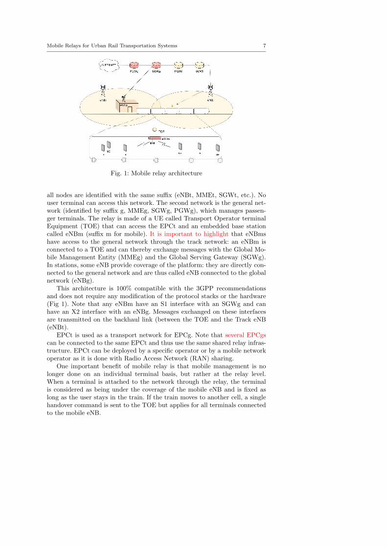
Fig. 1: Mobile relay architecture
all nodes are identified with the same suffix (eNBt, MMEt, SGWt, etc.). Nouser terminal can access this network. The second network is the general net-work (identified by suffix g, MMEg, SGWg, PGWg), which manages passen-ger terminals. The relay is made of a UE called Transport Operator terminalEquipment (TOE) that can access the EPCt and an embedded base stationcalled eNBm (suffix m for mobile). It is important to highlight that eNBmshave access to the general network through the track network: an eNBm isconnected to a TOE and can thereby exchange messages with the Global Mo-bile Management Entity (MMEg) and the Global Serving Gateway (SGWg).In stations, some eNB provide coverage of the platform: they are directly con-nected to the general network and are thus called eNB connected to the globalnetwork (eNBg).
This architecture is 100% compatible with the 3GPP recommendationsand does not require any modification of the protocol stacks or the hardware(Fig 1). Note that any eNBm have an S1 interface with an SGWg and canhave an X2 interface with an eNBg. Messages exchanged on these interfacesare transmitted on the backhaul link (between the TOE and the Track eNB(eNBt).
EPCt is used as a transport network for EPCg. Note that several EPCgscan be connected to the same EPCt and thus use the same shared relay infras-tructure. EPCt can be deployed by a specific operator or by a mobile networkoperator as it is done with Radio Access Network (RAN) sharing.
One important benefit of mobile relay is that mobile management is nolonger done on an individual terminal basis, but rather at the relay level.When a terminal is attached to the network through the relay, the terminalis considered as being under the coverage of the mobile eNB and is fixed aslong as the user stays in the train. If the train moves to another cell, a singlehandover command is sent to the TOE but applies for all terminals connectedto the mobile eNB.

8 Mauricio Iturralde et al.
S1-APIP (user)
GTP-U
UDP
IP
SCTP
IP
PDCP PDCP
RLC RLC
MAC
Physical layer (radio)
Protocol Stack onthe backhaul(TOE-eNBt)
UserData
eNBm-MME-gS1-MMEsignaling
User IPpayload
IP header
UDP header
GTP-U header
IP header
MAC/RLC/PDCPheader
S1-AP messagethat possibly
includes a NASmessage
SCTP header
IP header
MAC/RLC/PDCPheader
Headers for auser packet onthe backhaul
Headers for asignaling message
on the backhaul
6
20
8
12
20
6
20
44
bytes bytes
Fig. 2: Protocol stack and different headers on the backhaul
3.2 Analysis of the header sizes
As shown in figure 2, the counterpart of mobile relays is additional headers.Due to the use of two EPC networks there is an additional level of encapsu-lation and thus extra-headers (right part of figure 2) compared to a standardarchitecture.
In a standard radio interface, a user IP packet is transported by PacketData Convergence Protocol (PDCP) and the header size due to PDCP, RadioLink Control (RLC) and MAC is typically 6 bytes. With IPv4, the IP header is20 bytes. The header size including IP is thus 26 byte. With a relay, the tunnelis set over the radio backhaul. The following headers are thus added to eachtunneled packet: 12 bytes for GTP [16] (or 8 bytes if there is no numbering),8 bytes for User Datagram Protocol (UDP) and 20 bytes for IP. The totalheader size is thus 26 + 40 = 66 bytes.
For Radio Resource Control (RRC) signaling messages, the header is also6 bytes for a standard radio interface. Most signaling messages include a Non-Access Stratum (NAS) part and are thus exchanged between the terminaland the MME. When a mobile relay is used, they are exchanged betweenthe terminal and the MMEg through the backhaul. The additional header isdue to the use of IP, Stream Control Transmission Protocol (SCTP) and S1Application Protocol (S1-AP) protocols. The structure of SCTP messages iscomplex [35]. We assume that a message includes the standard SCTP header(12 bytes), an acknowledgement chunk (16 bytes) and a data chunk (the headeris 16 bytes), which gives a total of 44 bytes. From IP to S1-AP (excluded), thetotal header size is thus 6 + 20 + 44 = 70 bytes.

Mobile Relays for Urban Rail Transportation Systems 9
4 Signaling Analysis
4.1 Overview of the test-bed
4.1.1 General architecture
The test-bed is built on the Amarisoft solution [5], which is fully compati-ble with off-the-shelf terminals. Digital signal processing and all the protocolstacks in their entirety are pure software operations running on a standard PC.The high-frequency radio signal is generated and sampled by a radio module.We use several instances of Amarisoft: one on a PC, which acts as the eNBg;a second one with an LTE-dongle and a radio module, which acts as a relay(eNBm and ToE); and a third one, which acts as the eNBt and includes corenetwork functions (MMEt, SGWt, PGWt, MMEg, SGWg and PGWg) andwhich is connected to the local fixed network and the eNBg (see figure 3). Anadditional computer is used as a controller to have automatic tests.
Fig. 3: Implementation of the test-bed
The transmission is made in frequency division duplex mode in the 2.6GHz band. In order to avoid interference between the access and the backhaullinks, two separate carriers are used. The bandwidth for each carrier is 5-MHzto avoid processing overload in the computer.
4.1.2 Tested scenarios
Our focus is on the signaling load. The main part is due to mobility manage-ment. With mobile relay, there is only one handover for all terminals when amoving train enters a new cell. The signaling load is thus very low. Further-more, this type of handover was analyzed in our previous work [22] and we donot consider it in this paper. However, at a station there are multiple mobilityscenarios as shown in Figure 4, which should be studied.
We thus consider the following scenarios:

10 Mauricio Iturralde et al.
– a user with a terminal in idle mode enters a train,– a user with a terminal in idle mode leaves the train,– a user with an active session (terminal in connected mode) enters a train,
known as an on-boarding handover,– a user with an active session leaves the train, known as an off-boarding
handover,– a user can of course stay in the train but this does not in itself generate
specific signaling.
The sporadic nature of data flows also generates signaling between an eNBand the core network. We thus consider the following cases:
– a user does not use his/her terminal for a while and the eNBm triggers anRRC release, putting the terminal back in idle mode,
– a user uses his/her terminal after a pause and the RRC is resumed, aprocedure known as a Service Request.
4.2 Size of signaling messages
Table 1: Signaling for on-boarding handover on the S1 (example)
SourceDesti-nation
Back-haul
Proto-col
Size Name of the message
eNBg eNBm D X2AP 1128 HandoverRequesteNBm eNBg U X2AP 138 HandoverRequestAcknowledgeeNBg eNBm D X2AP 39 SNStatusTransfereNBm MMEg U S1AP 69 PathSwitchRequestMMEg eNBm D S1AP 56 PathSwitchRequestAcknowledgeeNBm eNBg U X2AP 19 UEContextReleaseeNBm MMEg U S1AP 108 Tracking area update requestMMEg eNBm D S1AP 53 Tracking area update accepteNBm MMEg U SCTP 0 SACKeNBg eNBm D SCTP 0 SACK
Total size D 1276U 334
Number of D 4AP messages U 4
We ran each procedure listed in section 4.1.2 on the testbed. We analyzedthe number of messages and the size of each message on the S1-interface be-tween the eNBm and the MMEg or on the X2-interface between the eNBm andthe eNBg. Note that we only consider messages transmitted on the backhaullink because it is the interface specific to mobile relaying. Signaling on otherinterfaces is exactly the same as that in a standard mobile network. An exam-ple is shown in table 1 for on-boarding handover. For each procedure we countthe number of S1AP and X2AP messages and the total number of bytes fordownlink and uplink. We assume that pure SCTP messages (e.g. SACK) arepiggy-backed by application messages. We thus assume that the final SACKshown in table 1 for a given UE are included in signaling messages concerning

Mobile Relays for Urban Rail Transportation Systems 11
Fig. 4: Studied signaling scenarios
other UEs. As explained in section 3.2, the additional header size from thephysical layer up to SCTP is 70 bytes. From table 1, we get a total numberof uplink signaling bytes for on-boarding handover of 334 + 4× 70 = 614 (and1276+4×70 = 1556 for downlink). The results for all procedures are computedwith the same method and are shown in table 1.
4.3 Signaling for On-boarding and Off-boarding
In this subsection, we evaluate the signaling load when passengers enter orleave a train at a station. As shown in table 2, there is far less signaling foron and off boarding for a terminal in idle state than in connected state. Wethus consider a scenario in which all passengers have a terminal in connectedstate, which is clearly a worst case scenario. Based on the estimation of SGP,the train stop was assumed to be 45 seconds. In peak hours, there are up to

12 Mauricio Iturralde et al.
Table 2: Signaling sizes for different scenarios
Downlink Uplink
ScenarioNumber
ofmessages
Totalnumber of
bytes
Numberof
messages
Totalnumber of
bytes
idle-mode on-boarding 3 399 2 233idle-mode off-boarding 0 0 0 0on-boarding handover 4 614 4 1556off-boarding handover 2 1420 3 534
RRC disconnection 2 184 1 91RRC connection 2 237 1 232
1000 passengers in a train. Up to half of the people get off at an importantstation and the same amount get on. We thus assume 500 off-boarding and500 on-boarding handovers.
The average signaling bit rate Sd in kbps on the downlink is thus (fromtable 2):
Sd = 500 × 8 × 614 + 1420
1000 × 45= 181 kbps. (1)
Similarly, the bit rate Su on the uplink is:
Su = 500 × 8 × 1556 + 534
1000 × 45= 186 kbps. (2)
An upper bound of the signaling rate due to on and off boarding is thus 190kbps both for the uplink and the downlink. This signaling is transmitted whenthe train is in a station and thus fixed. The link budget can be easily optimized.With a 20-MHz FDD radio interface and a 2×2 MIMO, the maximum bit rateis 150 Mbps. If we assume that the average capacity is 50% of the maximumbit rate, the amount of signaling is thus 0.25% of the capacity, which is quitelow.
4.4 Activity model of terminals
In this sub-section, we characterize the signaling load due to the sporadicnature of data flows: there are frequent RRC disconnections and reconnections.We first present the analytical model and then use it to compute the signalingload.
4.4.1 Source traffic model
For any positive random variable tX, let fX(t), FX(t) and FX(t) be its prob-ability density function (PDF), cumulative distribution function (CDF) andcomplementary CDF (CCDF), respectively. Note that if
∫∞0FX(t)dt exists,
then this integral gives the expectation E[tX] of tX.We consider the model inside a Web browsing session as illustrated in the
top part of figure 5 (see also figure 7). The user downloads Web pages: the time

Mobile Relays for Urban Rail Transportation Systems 13
Fig. 5: Illustration of activity and reading times
Fig. 6: Activity model with related RRC states
to download is modelled as a random variable tA (A stands for activity). Theuser then reads the page and we similarly define tR (R stands for reading). Thedistributions of tA and tR can be general. The only assumption we make isthat tR and tA are two independent variables: the value of tA has no influenceon tR.
As long as the download is progressing, an RRC connection is maintained.Just after the end of the loading phase, an inactivity timer is launched. Let TO
be the initial value of the timer. If another Web page is requested before thetimer expires, the UE stays in RRC Connected state. In other cases, a radioresource release procedure is triggered and the terminal switches to state I (foridle). As soon as a new transfer is activated, a Service Request Procedure isexecuted. An example of this scenario is given in figure 5.
A terminal can be in 3 states, namely A, B and I, as shown in figure 6.State B corresponds to at most the first TO seconds after the end of the pagetransfer. Note that the terminal is in RRC connected state for both A and B.We thus define state C as including both states A and B.
Our objective is to compute the probability for a terminal to be in idlestate and the average number of service request procedures per time unit.Note that the average number of radio resource release procedures is equal tothe average number of service request procedures at the equilibrium.
14 Mauricio Iturralde et al.
4.4.2 Idle state probability and average service request rate
We first consider a UE that switches to idle mode. When entering state I, TO
of the reading phase has already been used in state B. Thus, tI = tR − TO.Hence, by using the formula of conditional probabilities
P(tI > t) = P[tR > t+ TO/tR > TO] =FR(t+ TO)
FR(TO). (3)
For any positive random variable, the mean is the integral of the CCDF if thisintegral converges. The mean idle time is thus:
E[tI] =
∫ ∞
0
P(tI > t)dt =
∫∞TOFR(t)dt
FR(TO). (4)
We now want to determine E[tC]. A UE can stay in state C while switch-ing an unlimited number of times from state A to state B and reciprocally.The finite sate machine that corresponds to states A, B and C and the possi-ble transitions is a memoryless process. We can use renewal theory [12]: letconsider a terminal that was in idle state and for which a transmission phasestarts. The initial state is A. The expected remaining time is E[tC]. The UEmakes at least one transmission during E[tA] and then
– with probability P[tR ≥ TO] = FR(TO), the UE stays in state B during TO
and then switches to idle state,– with probability P[tR < TO] = FR(TO), it stays in addition in state B dur-
ing E[tR/tR < TO] and then switches again to state A. Thus, the expectedremaining time is E[tC].
From the above, we get:
E[tC] = E[tA] + FR(TO)TO + FR(TO) (E[tR/tR < TO] + E[tC]) . (5)
By definition, E[tR/tR < TO] =∫ TO
0tfR(t)dt/FR(TO). By integration by
parts, we get:
E[tR/tR < TO] =−FR(TO)TO +
∫ TO
0FR(t)dt
FR(TO). (6)
Combining (5) and (6) and after some elementary computational steps, weget
E[tC] =E[tA] +
∫ TO
0FR(t)dt
FR(TO). (7)
When we consider states I and C, we have a simple 2-state process wherethe terminal is alternately in one of the two states. The average number oftransitions λt per unit time from RRC idle state to RRC connected state isthus λt = 1/(E[tC] + E[tI]). From (4) and (7), we deduce
λt =FR(TO)
E[tA] + E[tR]. (8)

Mobile Relays for Urban Rail Transportation Systems 15
The probability ΠI of being in state I is E[tI]/(E[tC] + E[tI]). We get
ΠI =
∫∞TOFR(t)dt
E[tA] + E[tR]. (9)
The authors of [32] carried out a very large measurement study but onfixed computers. They found that reading time follows a log-normal distri-bution. The average reading time is 39.7 seconds and the standard deviationis 324.92 seconds. This corresponds to µ = 1.5717 and σ = 2.0541 and notto µ = −0.495204 and σ = 2.7731 as indicated in [32]. From section 6.1, weget E[tA] = 10 seconds. This value was obtained for a moderate number ofpassengers (100). If there are more passengers, E[tA] is larger and the numberof disconnections/reconnections per unit time is smaller. Hence, regarding thesignaling load, we consider the worst case.
We consider a range from 0 to 10 seconds for radio inactivity timer TO.Using (8) and (9), we compute the service request rate and the probability fora terminal to be in idle state, respectively, as shown in table 3.
Table 3: Service Request rate and idle-state probability for different timervalues when the reading time is a log-normal random variable with mean 39.7s and E[tA] = 10 s
Initial value of the timer (TO) 0 s 2 s 5 s 10 s
Idle state probability 0.79 0.76 0.73 0.69
Service Request rate (s−1) 1/50 1/75 1/101 1/138
A commonly agreed value for TO is 5 seconds. In that case, λC = 1/101service requests per second for a given terminal. For each connection request,there is a corresponding resource release procedure. For a train with 1000 pas-sengers (all using their smart phones), there are 2×1000/101 = 19.8 signalingrequests per second. The corresponding signaling bit rate is deduced from ta-ble 2. We get 1000 × 8 × (184 + 237)/101 = 33.4 kbps on the downlink and1000× 8× (91 + 232)/101 = 25.6 kbps on the uplink. Considering a a 20-MHzsystem and a 75-Mbps capacity, this represents less than 0.05 % of the bit-rate.
To conclude, if we consider both user mobility (see 4.3) and the sporadicnature of the data flows (see 4.4), the signaling load represents less than 0.3 %of the backhaul capacity. It is thus quite low and does not have a major impacton the performance of the system. We thus neglect it in section 5.
5 Performance Analysis in Loaded Conditions
In this section, we analyze and test the achievable benefits brought by thedeployment of mobile relays in loaded conditions. Our benchmark is a networkwithout any relay, which we call direct mode. We consider two representativeservices, namely Web browsing and telephony.
16 Mauricio Iturralde et al.
5.1 Transmitted Services
5.1.1 Web browsing
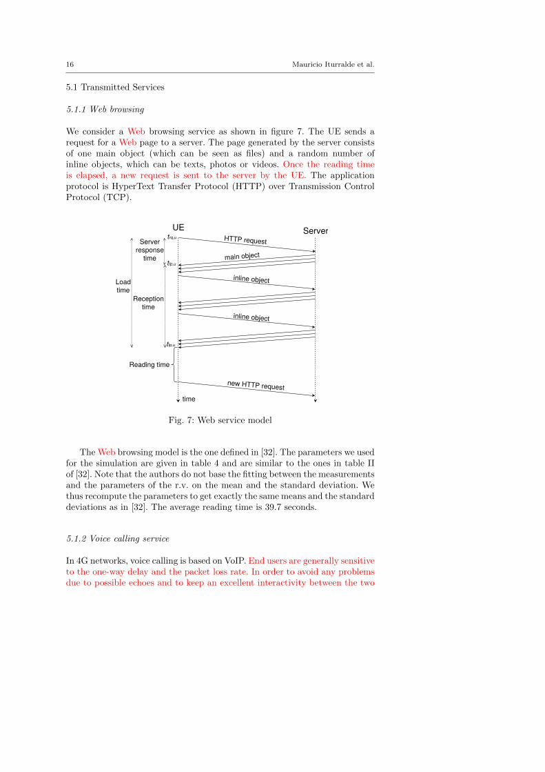
We consider a Web browsing service as shown in figure 7. The UE sends arequest for a Web page to a server. The page generated by the server consistsof one main object (which can be seen as files) and a random number ofinline objects, which can be texts, photos or videos. Once the reading timeis elapsed, a new request is sent to the server by the UE. The applicationprotocol is HyperText Transfer Protocol (HTTP) over Transmission ControlProtocol (TCP).
UE ServerHTTP request
inline object
new HTTP request
Reading time
main object
inline object
time
trq,u
tfp,u
tlp,u
Serverresponse
time
Receptiontime
Loadtime
Fig. 7: Web service model
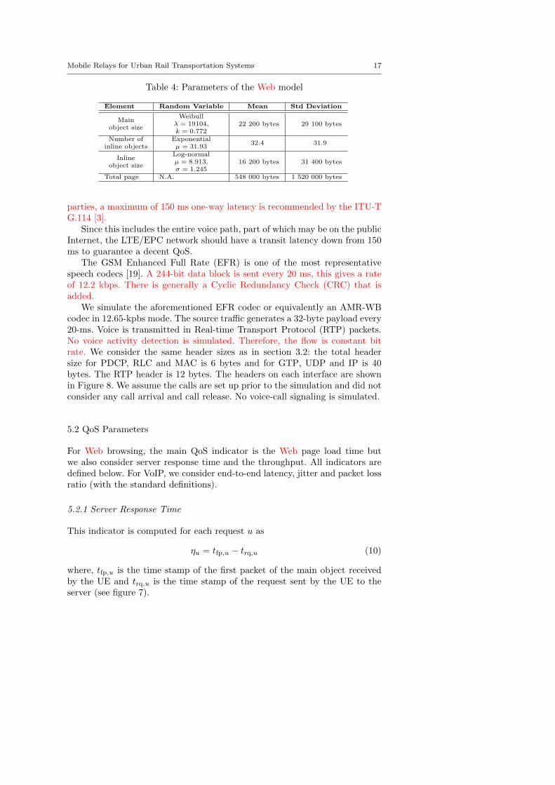
The Web browsing model is the one defined in [32]. The parameters we usedfor the simulation are given in table 4 and are similar to the ones in table IIof [32]. Note that the authors do not base the fitting between the measurementsand the parameters of the r.v. on the mean and the standard deviation. Wethus recompute the parameters to get exactly the same means and the standarddeviations as in [32]. The average reading time is 39.7 seconds.
5.1.2 Voice calling service
In 4G networks, voice calling is based on VoIP. End users are generally sensitiveto the one-way delay and the packet loss rate. In order to avoid any problemsdue to possible echoes and to keep an excellent interactivity between the two
Mobile Relays for Urban Rail Transportation Systems 17
Table 4: Parameters of the Web model
Element Random Variable Mean Std Deviation
Mainobject size
Weibullλ = 19104,k = 0.772
22 200 bytes 29 100 bytes
Number ofinline objects
Exponentialµ = 31.93
32.4 31.9
Inlineobject size
Log-normalµ = 8.913,σ = 1.245
16 200 bytes 31 400 bytes
Total page N.A. 548 000 bytes 1 520 000 bytes
parties, a maximum of 150 ms one-way latency is recommended by the ITU-TG.114 [3].
Since this includes the entire voice path, part of which may be on the publicInternet, the LTE/EPC network should have a transit latency down from 150ms to guarantee a decent QoS.
The GSM Enhanced Full Rate (EFR) is one of the most representativespeech codecs [19]. A 244-bit data block is sent every 20 ms, this gives a rateof 12.2 kbps. There is generally a Cyclic Redundancy Check (CRC) that isadded.
We simulate the aforementioned EFR codec or equivalently an AMR-WBcodec in 12.65-kpbs mode. The source traffic generates a 32-byte payload every20-ms. Voice is transmitted in Real-time Transport Protocol (RTP) packets.No voice activity detection is simulated. Therefore, the flow is constant bitrate. We consider the same header sizes as in section 3.2: the total headersize for PDCP, RLC and MAC is 6 bytes and for GTP, UDP and IP is 40bytes. The RTP header is 12 bytes. The headers on each interface are shownin Figure 8. We assume the calls are set up prior to the simulation and did notconsider any call arrival and call release. No voice-call signaling is simulated.
5.2 QoS Parameters
For Web browsing, the main QoS indicator is the Web page load time butwe also consider server response time and the throughput. All indicators aredefined below. For VoIP, we consider end-to-end latency, jitter and packet lossratio (with the standard definitions).
5.2.1 Server Response Time
This indicator is computed for each request u as
ηu = tfp,u − trq,u (10)
where, tfp,u is the time stamp of the first packet of the main object receivedby the UE and trq,u is the time stamp of the request sent by the UE to theserver (see figure 7).

18 Mauricio Iturralde et al.
Fig. 8: VoIP packet headers in relay architecture.
5.2.2 Page Reception Time
This indicator is computed as
ξu = tlp,u − tfp,u (11)
where tlp,u is the time stamp of the last packet received by the UE.
5.2.3 Web Page Load Time
The Web page load time is merely the sum of the server response time andthe page reception time:
τu = ηu + ξu (12)
5.2.4 Throughput
This parameter measures the throughput per request. Its value is obtainedwhen downloading a Web page. This parameter is computed as:
αu =Bu
tlp,u − tfp,u(13)
where Bu is the number of bytes received after request u.

Mobile Relays for Urban Rail Transportation Systems 19
5.2.5 Throughput in worst conditions
It is well known that user perception is mainly influenced by the lowest qualitythey experience. The worst case is represented by the transition from one cellto another because the received signal is weak and also because the shortinterruption due to handover may induce a reduction of the flow by TCP.We do not measure the handover duration because it is not significant initself. However, we consider the throughput only for page transmissions thatexperience a handover. Let tH0 be the time at which a handover is made. Wecompute αu with (13) only if tfp,u ≤ tH0 and tlp,u ≥ tH0.
5.3 Simulation Environment
To perform our tests we used the network simulator version 3 (ns-3) [1]. The ns-3 LTE module simulates the LTE model and the EPC model. The LTE modelincludes the LTE Radio Protocol stack (RRC, PDCP, RLC, MAC, PHY) andthe EPC model includes core network interfaces, protocols and entities. Theseentities and protocols reside within the SGW, PGW and MME nodes, andpartially within the eNB nodes. We use the standard ns-3 LTE model withdirect transmission between UEs in the train and the network as the referencemode.
We implemented the mobile relay architecture module in ns-3 based onthe classic LTE module (see Fig. 1). The encapsulation and decapsulationmechanisms are entirely simulated. We tested the performance of the mobilerelay architecture and evaluated it against a direct transmission scenario.
In our scenario a train moves in a straight line at a constant speed of 100kmph. Base stations (eNBt) are uniformly deployed along the track and havea 600-m radius. The inter-site distance is thus 1200 m. X2-based handoversare activated only for eNbts. Terminals are fixed within the train. We do notsimulate any stops at stations. This is necessary to have enough Web servicerequests in the same conditions and to guarantee the statistical significance ofthe results.
The eNbt and the eNbm transmit on different frequencies. Therefore, inter-cell interference is avoided. At each simulation the train goes through 20 eNBts.
Three in-train loads are considered : 20, 60 and 100 mobile users. 60%of the passengers browse the Web and the remaining 40% carry out VoIPcommunications. The simulation parameters are described in detail in Table5.
6 Numerical Results
In order to analyse the obtained results, several figures represent the statisticaldistribution of values by using boxplots with the upper quartile, median andlower quartile. The points which fall more than 1.5 times the interquartile

20 Mauricio Iturralde et al.
Table 5: Simulation Parameters
Parameters Value
System Type FDDTemperature 290 KSimulation Time 100 sTrain penetration loss 15 dBFor TOE and eNbt (Backhaul link)Propagation Loss Model Kun2600 MHzNumber of TOEs 1Number of eNbt 20eNbt Cell’s radius 600 meNbt Tx Power 27 dBmTOE Tx Power 23 dBmTOE Noise Figure 7 dBeNbt Noise Figure 3 dBBandwidth for eNbt 20 MHzDownlink Frequency for eNbt 2620.0 MHzUplink Frequency for eNbt 2500.0 MHzMac Scheduler Proportional FairnessHandover Algorithm Event A3 [13]For UEm and eNbm (Access link)Propagation Loss Model Friis ModelNumber of UEm 20 up to 100Number of eNbm 1eNbm Cell’s radius 100 mUEm movement speed 100 kmpheNbm Tx Power 27 dBmUEm Tx Power 23 dBmUEm Noise Figure 7 dBeNbt Noise Figure 3 dBBandwidth for eNbm 20 MHzDownlink Frequency for eNbm 2655.0 MHzUplink Frequency for eNbm 2535.0 MHzMac Scheduler Proportional Fairness
range above the third quartile or below the first quartile are known as outliers.The whiskers depict the maximum and minimum values excluding outliers
6.1 Web page load time
Figure 9 depicts the effect of the mobile relay in terms of page load time whenthe train contains 12, 36 and 60 users Web browsing (within a total of 20, 60and 100 users). For 12 users the median is less than one second for both relayand direct modes. For 36 users the median is reduced from 10 to 5 s and is thusdivided by 2. The maximum time is also divided by 2. For 60 users, the meanload time is drastically reduced from 20 to 7 s. The max value is reduced from248 to 81 s. Users are generally very sensitive to such a reduction of the loadtime. In all cases, the maximum load time is always smaller in relay mode. Aninteresting fact to highlight is that the values of 60 users in relay mode aresmaller than the direct mode with 36 users.

Mobile Relays for Urban Rail Transportation Systems 21
-2
-1.5
-1
-0.5
0
0.5
1
1.5
2
2.5
3
12 12(r) 36 36(r) 60 60(r)
Load Time [log10 of seconds]
Number of Users
directrelay(r)
Fig. 9: Boxplot of Web page load time (log scale)
6.2 Throughput
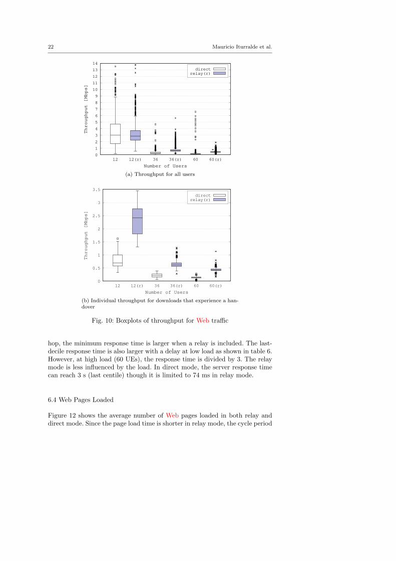
Figure 10a shows the reached throughput for Web browsing. When the traincontains 12 users, direct mode shows better performance than relay mode (e.g.3.1 Mbps vs 2.9 Mbps for median values). Nevertheless, the final user does notexperience a QoS degradation since there are enough resources to serve allusers. On the other hand, relay mode provides higher minimal throughputthan direct mode (e.g. 0.4 Mbps vs 0.2 Mbps). When the train contains 36users, relay mode shows better performance than direct mode (e.g. 3.1 Mbps vs6.5 Mbps for median values). The maximum and minimum throughput valuesare also higher in relay mode.
When the train contains 60 users, the relay mode shows better performancethan direct mode (e.g. 4.2 Mbps vs 2.1 Mbps for median values). The maxi-mum and minimum throughput values are also higher in relay mode; however,several outliers show higher throughput in direct mode. Those outliers are dueto transmissions performed when the train is very close to the eNBt.
Figure 10b depicts the throughput only for users that started the trans-mission before the handover and finished the transmission after the handover.Results show that users in relay mode reach a throughput three times as highas those in direct mode, e.g. 0.7 Mbps vs 2.41 Mbps, 0.21 Mbps vs 0.64 Mbpsand 0.15 Mbps vs 0.45 Mbps (for median values) for 12, 36 and 60 users, re-spectively. These results confirm the benefit of deploying a mobile relay on theQoS of sessions that experience a handover (see subsection 5.2.5).
6.3 Server Response Time
In order to have a better understanding of the behaviour of the system, weshow the cdf of the server response time in figure 11. Due to the additional
22 Mauricio Iturralde et al.
0
1
2
3
4
5
6
7
8
9
10
11
12
13
14
12 12(r) 36 36(r) 60 60(r)
Throughput [Mbps]
Number of Users
directrelay(r)
(a) Throughput for all users
0
0.5
1
1.5
2
2.5
3
3.5
12 12(r) 36 36(r) 60 60(r)
Throughput [Mbps]
Number of Users
directrelay(r)
(b) Individual throughput for downloads that experience a han-dover
Fig. 10: Boxplots of throughput for Web traffic
hop, the minimum response time is larger when a relay is included. The last-decile response time is also larger with a delay at low load as shown in table 6.However, at high load (60 UEs), the response time is divided by 3. The relaymode is less influenced by the load. In direct mode, the server response timecan reach 3 s (last centile) though it is limited to 74 ms in relay mode.
6.4 Web Pages Loaded
Figure 12 shows the average number of Web pages loaded in both relay anddirect mode. Since the page load time is shorter in relay mode, the cycle period

Mobile Relays for Urban Rail Transportation Systems 23
0.5
0.6
0.7
0.8
0.9
1
-2 -1.5 -1 -0.5 0 0.5 1
CDF
Server Response Time [log10 of seconds]
direct 60 UErelay 60 UE
direct 36 UErelay 36 UE
direct 12 UErelay 12 UE
Fig. 11: CDF of the http server response time (in log scale)
Direct Relay Direct Relay Direct Relay12 UE 12 UE 20 UE 20 UE 60 UE 60 UE
Last decile 19 38 20 38 139 39Last centile 61 46 285 63 3062 74
Table 6: Last decile and last centile of the http server response time (in ms)
(see figure 11) is decreased for the same reading time. Users can make a largernumber of requests (1021 vs 700 for 60 users). This reflects the fact that relaymode stimulates the use of mobile services. Our simulation results show anincrease of 45%.
0
200
400
600
800
1000
1200
12 36 60
Web Pages Loaded
Number of Users
directrelay
Fig. 12: Number of Web pages loaded

24 Mauricio Iturralde et al.
6.5 Latency of VoIP flows
Figure 13 shows the distribution of latency. Since packets have more hops inrelay architecture, it is normal to have higher latency than in direct mode.However, the latency difference between the relay and the direct mode is re-duced as the number of users increases. The difference in median latency is 5ms for 8 users, 3 ms for 24 users and 1 ms for 40 users.
Since latency is lower down 40 ms, we can assume that a good voice callinginteraction is guaranteed in view of the fact that the latency threshold is 150ms. Furthermore, a simple Proportional Fairness (PF) scheduler is used. PFdoes not give any priority to VoIP packets. By using a dedicated bearer forVoIP packets on the backhaul, it is possible to grant a higher priority to VoIPpackets and to limit the latency rise.
6.6 Jitter of VoIP flows
Figure 14 shows the jitter distribution. Relay mode demonstrates lower jitter.When the train has few users, there is not a big difference in jitter. Neverthe-less, for 24 users, jitter is reduced from 16 ms to 13 ms and for 40 users, jitteris reduced from 27 ms to 24 ms in relay mode.
6.7 Packet Loss Ratio of VoIP flows
Figure 15 shows the packet loss ratio. In all cases, relay mode shows no packetloss (RLC mode is AM). On the other hand, direct mode shows a packet losslower than 1% for 8 and 24 users, and up to 4% when the train is carrying 40users.
For VoIP flow, both the packet loss and the jitter are reduced because thelink budget is much better with a relay. In direct mode, the packet erasurerate for an individual transmission is not negligible. The retransmissions inducevariable delays and thus jitter. In some cases, the packet cannot be decodedeven after the maximum number of transmissions, which gives packet losses.
6.8 Short analysis of the handovers
Although this work does not focus on handover mechanisms in mobile relays,we noticed an important fact to highlight in addition to the presented results.Since in-train users are moving in the same direction, the direct connectionbetween the eNBt and UEs leads to an increased handover failure rate. ARandom Access (RA) procedure is performed at the beginning of the han-dover execution phase. During the preparation phase, the target cell allocatesa unique RA preamble. This uniqueness guarantees a collision-free access. Thepreamble is released once the RA procedure is finished in the target cell. Each

Mobile Relays for Urban Rail Transportation Systems 25
5
10
15
20
25
30
35
40
8 8(r) 24 24(r) 40 40(r)
Latency [ms]
Users
directrelay(r)
Fig. 13: Boxplot of latency of VoIP flows
0
5
10
15
20
25
30
8 8(r) 24 24(r) 40 40(r)
Jitter [ms]
Users
directrelay(r)
Fig. 14: Boxplot of jitter of VoIP flows
cell has 64 preambles available, but only a limited part is reserved for thiscontention-less RA. In the case of preamble starvation, handovers are queued.
When the cell is highly loaded (i.e more than 60 users), this causes aconnection drop in the worst case (long queuing) and QoS degradation due toa delay increase in the best case. In the direct-mode simulation, we increase thenumber of preambles for contention-less access to avoid drops and to comparerelay mode with the best possible direct mode.
In relay mode since all the users are grouped, the eNBt performs the han-dover only for the TOE (seen as only one user). This means that there will beonly one preamble used per train when performing the handover, no matterthe number of UEs in the train.

26 Mauricio Iturralde et al.
0
0.5
1
1.5
2
2.5
3
3.5
4
8 8(r) 24 24(r) 40 40(r)
PLR [%]
Users
directrelay(r)
Fig. 15: Boxplot of Packet Loss Ratio of VoIP flows
7 Conclusion
This paper evaluates the performance of a mobile relay architecture for publictransportation systems. We base our evaluation on a testbed with real ra-dio transmissions and consider both the signaling issue and the throughputexperienced by users. A number of conclusions can be drawn.
The additional overhead due to multiple encapsulations has no significantimpact on performance, both for data and for signaling. Signaling uses a neg-ligible part of the bandwidth. As the bit rate is dramatically increased due toa much better link budget, deploying mobile relays is a very efficient way toincrease the QoS in public transportation.
The page load time is reduced, especially in high load conditions, comparedto a direct transmission. The server response time is also shorter despite thefact that there is an additional hop. We show that these improvements lead toan increase in the number of pages visited and are thus prone to stimulate theusage of mobile services. VoIP also takes advantage of mobile relays, especiallyregarding packet losses.
The relaying architecture proposed in this article is based on tunneling,which is reused in 5G networks without major modification of GTP in the userplane. Furthermore 4G and 5G technologies can be mixed: 5G base stationscan be connected to a 4G core network, and an eNB can be connected to a 5Gcore network. The next step of our work is to study how the new features of 5Gcan be used with mobile relays to provide an unprecedented user experiencefor passengers on public transportation.
References
1. ns-3 simulator. Available at: http://www.nsnam.org/

Mobile Relays for Urban Rail Transportation Systems 27
2. Mobile network subsystems. Common Functional Specification D730 Issue B, RACE(Research in Advanced Communications in Europe) Industrial Consortium (1991)
3. One-way transmission time. ITU-T Recommendation G.114, International Telecommu-nication Union (2003)
4. Addali, K.M., BenMimoune, A., Khasawneh, F.A., Saied, A.M., Kadoch, M.: Dual-backhaul links in lte - a mobile relay system for high-speed railways. In: 2016 IEEE4th International Conference on Future Internet of Things and Cloud Workshops (Fi-CloudW), pp. 98–102 (2016)
5. Amarisoft: Amari lte 100, software lte base station on pc. Available at:http://www.amarisoft.com/
6. Berisha, T., Svoboda, P., Ojak, S., Mecklenbrauker, C.F.: Cellular network quality im-provements for high speed train passengers by on-board amplify-and-forward relays.In: 2016 International Symposium on Wireless Communication Systems (ISWCS), pp.325–329 (2016). DOI 10.1109/ISWCS.2016.7600923
7. Calle-Sanchez, J., De-Antonio-Monte, D., Molina-Garcıa, M., Alonso, J.I.: Theoreticalanalysis and performance simulation of in-band lte mobile relays in railway environ-ments. In: 2014 28th International Conference on Advanced Information Networkingand Applications Workshops, pp. 725–730 (2014). DOI 10.1109/WAINA.2014.117
8. Calle-Sanchez, J., Molina-Garcıa, M., De-Antonio-Monte, D., Alonso, J.I.: Performanceevaluation of in-band lte mobile relays in high speed railway environments. In: 201444th European Microwave Conference, pp. 139–142 (2014)
9. Cao, J., Ma, M., Li, H., Fu, Y., Niu, B., Li, F.: Trajectory prediction-based handoverauthentication mechanism for mobile relays in lte-a high-speed rail networks. In: 2017IEEE International Conference on Communications (ICC), pp. 1–6 (2017)
10. Chen, J., Mai, Y.: Relay node mobility support in the lte-advanced networks. In: 201322nd Wireless and Optical Communication Conference, pp. 293–297 (2013)
11. Chen, Y.Y., Yan, F., Lagrange, X.: Performance analysis of cellular networks with mo-bile relays under different modes. Telecommunication systems 66(2), 217–231 (2017)
12. Cox, D.: Renewal theory. London: Methuen & Co (1970)13. Dimou, K., Wang, M., Yang, Y., Kazmi, M., Larmo, A., Pettersson, J., Muller, W.,
Timner, Y.: Handover within 3gpp lte: Design principles and performance. In: IEEEVehicular Technology Conference Fall (VTC 2009-Fall), pp. 1–5 (2009)
14. Ericsson: Ericsson mobility report. https://www.ericsson.com/mobility-report (2019)15. Gamboa, J., Demirkol, I.: Softwarized lte self-backhauling solution and its evaluation.
In: 2018 IEEE Wireless Communications and Networking Conference (WCNC), pp. 1–6(2018)
16. 3rd Generation Partnership Project: General packet radio system (gprs); tunnellingprotocol user plane (gtpv1-u) (release 8). V8.5.0 Technical Specification 29.281, 3GPP(2010)
17. 3rd Generation Partnership Project: Relay architectures for e-utra (lte-advanced), (re-lease 9). V9.0.0 Technical Report 36.836, 3GPP (2010)
18. 3rd Generation Partnership Project: Evolved Universal Terrestrial Radio Access (E-UTRA); Study on mobile relay (Release 12). V12.0.0 Technical Report 36.836, 3GPP(2014)
19. 3rd Generation Partnership Project: Universal mobile telecommunications system(umts); lte; codec for enhanced voice services (evs); (release 14). V14.2.0 TechnicalSpecification 26.445, 3GPP (2018)
20. Ghazzai, H., Bouchoucha, T., Alsharoa, A., Yaacoub, E., Alouini, M., Al-Naffouri, T.Y.:Transmit power minimization and base station planning for high-speed trains with mul-tiple moving relays in ofdma systems. IEEE Transactions on Vehicular Technology66(1), 175–187 (2017)
21. Iturralde, M., Galezowski, T., Lagrange, X.: Performance of mobile relays in loaded con-ditions for railway transportation. In: 2018 16th International Conference on IntelligentTransportation Systems Telecommunications (ITST) (2018)
22. Kerdoncuff, T., Galezowski, T., Lagrange, X.: Mobile relay for lte: proof of concept andperformance measurements. In: Vehicular Technology Conference (VTC Spring), 2018IEEE 87th (accepted paper). IEEE (2018)

28 Mauricio Iturralde et al.
23. Laiyemo, A.O., Pennanen, H., Pirinen, P., Latva-aho, M.: Effective deployment of co-operative moving relay nodes in a high speed train. In: 2016 Wireless Days (WD), pp.1–6 (2016). DOI 10.1109/WD.2016.7461448
24. Liu, Z., Fan, P.: An effective handover scheme based on antenna selection inground–train distributed antenna systems. IEEE Transactions on Vehicular Technology63(7), 3342–3350 (2014)
25. Liu, Z., Zhou, E., Fan, P., Hao, L.: Tradeoff of capacity and handover performance inhigh speed railway wireless communications. In: 2016 IEEE 83rd Vehicular TechnologyConference (VTC Spring), pp. 1–5 (2016). DOI 10.1109/VTCSpring.2016.7504508
26. Oliva, D., Alonso, J.I.: A two-hop mimo relay architecture using lte and millimeter wavebands in high speed trains. In: 2018 IEEE Wireless Communications and NetworkingConference (WCNC), pp. 1–6 (2018). DOI 10.1109/WCNC.2018.8377369
27. Oliva Sanchez, J.D., Alonso, J.I.: A two-hop mimo relay architecture using lte andmillimeter wave bands in high-speed trains. IEEE Transactions on Vehicular Technology68(3), 2052–2065 (2019)
28. Pan, M., Lin, T., Chen, W.: An enhanced handover scheme for mobile relays in lte-ahigh-speed rail networks. IEEE Transactions on Vehicular Technology 64(2), 743–756(2015). DOI 10.1109/TVT.2014.2322374
29. Parichehreh, A., Spagnolini, U., Marini, P., Fontana, A.: Load-stress test of massivehandovers for lte two-hop architecture in high-speed trains. IEEE CommunicationsMagazine 55(3), 170–177 (2017)
30. Prados-Garzon, J., Laghrissi A.and Bagaa, M., Taleb, T.: A queuing based dynamic autoscaling algorithm for the lte epc control plane. In: 2018 IEEE Global CommunicationsConference (GLOBECOM 2018), Abu Dhabi, UAE (2018)
31. Prados-Garzon, J., Ramos-Munoz, J., Ameigeiras, P., Andres-Maldonado, P., Lopez-Soler, J.: Modeling and dimensioning of a virtualized mme for 5g mobile networks.IEEE Transactions on Vehicular Technology 66(5), 4383–4395 (2017)
32. Pries, R., et al.: An http web traffic model based on the top one million visited webpages. In: Euro-NF Conference in Next Generation Internet (NGI), 2012 IEEE 8th, pp.133–139. IEEE (2012)
33. Qian, X., Wu, H., Meng, J.: A dual-antenna and mobile relay station based handoverin distributed antenna system for high-speed railway. In: 2013 Seventh InternationalConference on Innovative Mobile and Internet Services in Ubiquitous Computing, pp.585–590 (2013). DOI 10.1109/IMIS.2013.103
34. Sanz-Gomara, A., Marın-Garcıa, J.A., Alonso, J.I.: Performance evaluation of mimoarchitectures with moving relays in high-speed railways. In: 2018 48th European Mi-crowave Conference (EuMC), pp. 716–719 (2018). DOI 10.23919/EuMC.2018.8541728
35. Stewart, R.R.: Stream control transmission protocol. RFC 4960, RFC Editor (2007).URL https://rfc-editor.org/rfc/rfc4960.txt
36. Tian, L., Li, J., Huang, Y., Shi, J., Zhou, J.: Seamless dual-link handover scheme inbroadband wireless communication systems for high-speed rail. IEEE Journal on Se-lected Areas in Communications 30(4), 708–718 (2012)
37. Zhang, C., Fan, P.: Providing services for the high-speed train and local users in thesame ofdma system: Resource allocation in the downlink. IEEE Transactions on WirelessCommunications 15(2), 1018–1030 (2016). DOI 10.1109/TWC.2015.2481431
38. Zhang, J., Du, H., Zhang, P., Cheng, J., Yang, L.: Performance analysis of 5g mobilerelay systems for high-speed trains. IEEE Journal on Selected Areas in Communicationspp. 1–13 (2020)
39. Zhu, X., Chen, S., Hu, H., Su, X., Shi, Y.: Tdd-based mobile communication solutionsfor high-speed railway scenarios. IEEE Wireless Communications 20(6), 22–29 (2013).DOI 10.1109/MWC.2013.6704470
40. Zufang, D., Suoping, L., Jaafar, G., Xiaokai, C.: Improvement and queuing analysis ofthe handover mechanism in the high-speed railway communication. TelecommunicationSystems 73(3), 383–395 (2020). DOI 10.1007/s11235-019-00651-y