mobile network evolution - startseite tu ilmenau network... · mobile network evolution andreas...
TRANSCRIPT

Mobile Network Evolution Andreas Mitschele-Thiel 1
Integrated Communication Systems Group
Mobile Network Evolution -
From GSM to LTE
Andreas Mitschele-Thiel
Mobile Network Evolution Andreas Mitschele-Thiel 2
Integrated Communication Systems Group
Outline
• Evolution from GSM to UMTS – Architecture – Packet handling – Resource management – Comparison with 802.11
• LTE + SAE = EPS – Features and requirements – Architecture – Protocols – Packet handling and resource management – Mobility management and HO – Self-organization
• Conclusions • References • Abbreviations
Mobile Network Evolution Andreas Mitschele-Thiel 3
Integrated Communication Systems Group
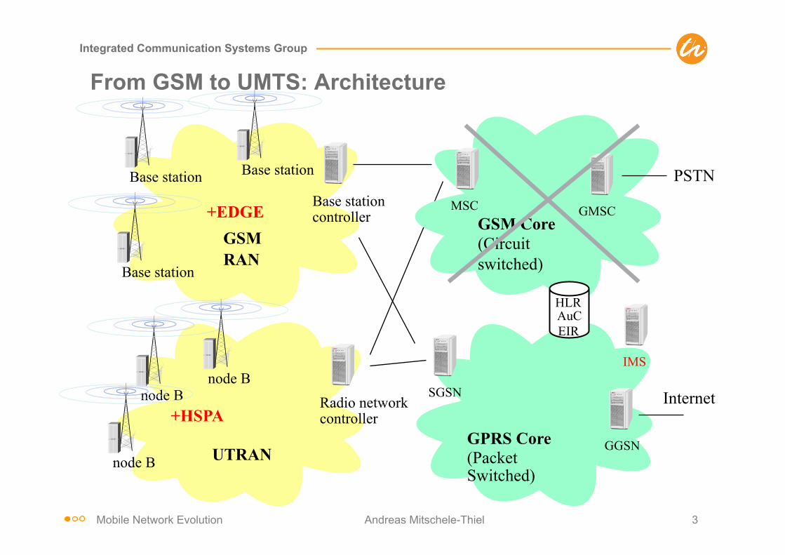
From GSM to UMTS: Architecture
GPRS Core (Packet Switched)
SGSN
GGSN
Internet
GSM RAN
Base station Base station controller
Base station
Base station
UTRAN
Radio network controller
node B node B
node B
MSC
PSTN
GSM Core (Circuit switched)
HLR AuC EIR
GMSC
IMS
+HSPA
+EDGE

Mobile Network Evolution Andreas Mitschele-Thiel 4
Integrated Communication Systems Group
From Circuit Switched to Packet Switched Communication
Connection (e.g. voice, CS data) => principle for GSM & UMTS RAN • clearly defined start and end times • no burstiness => dedicated channels
minutes
connection setup
connection release
Packet session => supported by GPRS core, IMS, SAE, HSPA, LTE • packet arrival times are typically unknown to the system • traffic is highly bursty => shared channels & packet scheduling
hours
seconds
Mobile Network Evolution Andreas Mitschele-Thiel 5
Integrated Communication Systems Group
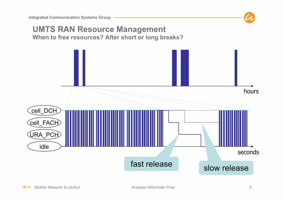
UMTS RAN Resource Management When to free resources? After short or long breaks?
hours
seconds
cell_DCH
URA_PCH
cell_FACH
idle
fast release slow release
Mobile Network Evolution Andreas Mitschele-Thiel 6
Integrated Communication Systems Group
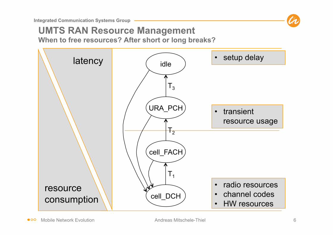
resource consumption
latency
• radio resources • channel codes • HW resources
• setup delay
• transient resource usage
cell_DCH
URA_PCH
cell_FACH
idle
T1
T2
T3
UMTS RAN Resource Management When to free resources? After short or long breaks?

Mobile Network Evolution Andreas Mitschele-Thiel 7
Integrated Communication Systems Group
slow release
fast release
+ reduced fixed cost – increase of transitive
cost
cell_DCH
URA_PCH
cell_FACH
idle
T1
T2
T3
– increase of fixed cost
+ decrease of transitive cost
+ decrease of mean call setup times
UMTS RAN Resource Management When to free resources? After short or long breaks?

Mobile Network Evolution Andreas Mitschele-Thiel 8
Integrated Communication Systems Group
UMTS Resource Management (control plane) A sophisticated QoS architecture
Transl. Transl.
Adm.Contr
.Adm.Contr
.Adm.Contr
.Adm.Contr
.Adm.Contr
.
RAB Manager
UMTS BS Manager
UMTS BS Manager
UMTS BS Manager
Subscr. Control
Adm./Cap. Control
MT Gateway CN EDGE UTRAN
Ext. Service Control
Local Service Control
Iu BS Manager
Radio BS Manager
Iu NS Manager
UTRA ph. BS M
Radio BS Manager
UTRA ph. BS M
Local BS Manager
Adm./Cap. Control
Adm./Cap. Control
Adm./Cap. Control
Iu BS Manager
Iu NS Manager
CN BS Manager
Ext. BS Manager
CN BS Manager
service primitive interface protocol interface
BB NS Manager
BB NS Manager
TE Ext. Netw.

Mobile Network Evolution Andreas Mitschele-Thiel 9
Integrated Communication Systems Group
UMTS Resource Management (user plane)
ResourceManager
Mapper
Classif.
Cond.
ResourceManager
ResourceManager
Mapper
ResourceManager
Mapper
ResourceManager
ResourceManager
Cond.
Classif.
Cond.
MT GatewayCN EDGEUTRAN
BB network serviceIu network serviceUTRA phys. BS
data flow with indication of direction
TE Ext.Netw.
Local BS External BS

Mobile Network Evolution Andreas Mitschele-Thiel 10
Integrated Communication Systems Group
Compare to 802.11 Resource Management
t
busy
boe
station1
station2
station3
station4
station5
packet arrival at MAC
DIFS boe
boe
boe
busy
elapsed backoff time
bor residual backoff time
busy medium not idle (frame, ack etc.)
bor
bor DIFS
boe
boe
boe bor DIFS
busy
busy
DIFS boe busy
boe
boe
bor
bor
Distributed Coordination Function (DCF) with Exponential Backoff
Mobile Network Evolution Andreas Mitschele-Thiel 11
Integrated Communication Systems Group
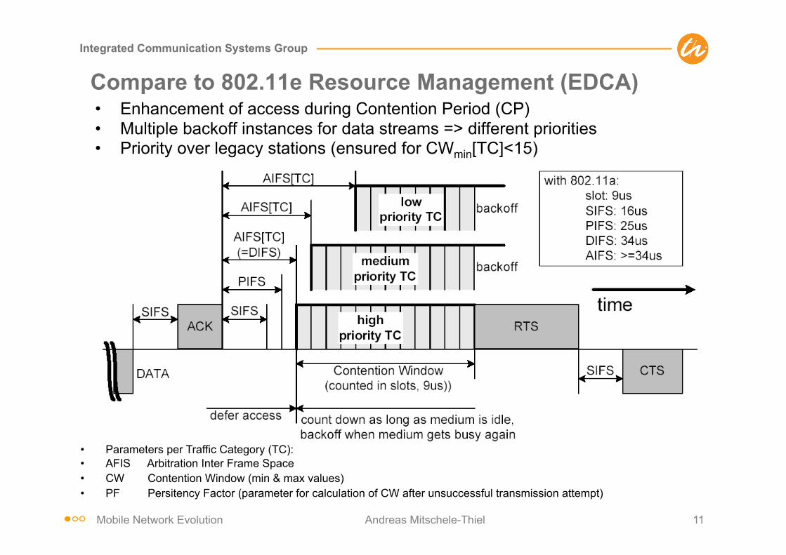
Compare to 802.11e Resource Management (EDCA) • Enhancement of access during Contention Period (CP) • Multiple backoff instances for data streams => different priorities • Priority over legacy stations (ensured for CWmin[TC]<15)
• Parameters per Traffic Category (TC): • AFIS Arbitration Inter Frame Space • CW Contention Window (min & max values) • PF Persitency Factor (parameter for calculation of CW after unsuccessful transmission attempt)
Mobile Network Evolution Andreas Mitschele-Thiel 12
Integrated Communication Systems Group
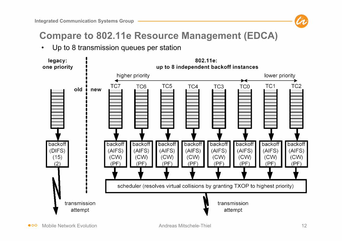
Compare to 802.11e Resource Management (EDCA) • Up to 8 transmission queues per station

Mobile Network Evolution Andreas Mitschele-Thiel 14
Integrated Communication Systems Group
UMTS vs. 802.11 system operation UMTS:
– pros: • full control of radio spectrum • wide-area coverage • full fledged and individual QoS control (similar to IntServ)
– cons: high initial overhead to set up business • high equipment cost • licence cost and spectrum availability • limited bandwidth • high administrative overhead to establish as a operator • acquisition of antenna locations
802.11: – pros: small cost to set up a business (in very dense areas)
• no license needed • ample spectrum • widely available handsets (though not very mobile) • simple authentication and accounting (credit cards) • no long-term contracting with users
– cons: • no control of radio spectrum (risk of investments in public areas) • limited coverage • limited QoS support (similar to DiffServ) • high installation cost (backhaul) in case of small traffic per area (use of mesh
networks to minimize backhaul cost) • no long-term binding of users to provider

Mobile Network Evolution Andreas Mitschele-Thiel 15
Integrated Communication Systems Group
From GSM to LTE/SAE: Protocols and Channels
GSM: voice-dominated, dedicated channels, heavy states GPRS: add support for packet data on shared channels; add IP-
based core network EDGE: increased packet data capacity for GSM systems UMTS: separate voice and packet data support; focus on dedicated
channels and heavy states, complicated RAN architecture and protocols due to macro diversity and QoS requirements
HSPA: improved support for packet data; emphasis on shared channels
IMS: support for IP-based services, e.g. voice (VoIP) LTE: strong packet data support (latency, throughput, control
overhead), limited state; simplified protocols; PS only, i.e. no CS core network

Mobile Network Evolution Andreas Mitschele-Thiel 16
Integrated Communication Systems Group
3GPP Evolution towards LTE/SAE – Background (1/3)
Discussion started in December 2004 State of the art then: • The HSPA extension for UMTS provides very efficient packet
data transmission capabilities, but UMTS should continue to be evolved to meet the ever increasing demand of new applications and user expectations
• 10 years have passed since the initiation of the 3G program and it is time to initiate a new program to evolve 3G which will lead to a 4G technology
Mobile Network Evolution Andreas Mitschele-Thiel 17
Integrated Communication Systems Group
3GPP Evolution towards LTE/SAE – Background (2/3)
• From the application/user perspectives, the UMTS evolution should target at significantly higher data rates and throughput, lower network latency and support of always-on connectivity
• From the operator perspectives, an evolved UMTS will make business sense if it: - provides significantly improved power and bandwidth
efficiencies - facilitates the convergence with other networks/technologies - reduces transport network cost - limits additional complexity

Mobile Network Evolution Andreas Mitschele-Thiel 18
Integrated Communication Systems Group
3GPP Evolution towards LTE/SAE – Background (3/3)
• Evolved-UTRA is a packet only network - there is no support for circuit-switched services (no MSC)
• Evolved-UTRA starts on a clean state - everything is up for discussion including the system architecture and the split of functionality between RAN and CN
• Led to 3GPP Study Item (Study Phase: 2005-4Q2006) • „3G Long-term Evolution (LTE)” for new Radio Access and • “System Architecture Evolution” (SAE) for Evolved Network
Mobile Network Evolution Andreas Mitschele-Thiel 19
Integrated Communication Systems Group
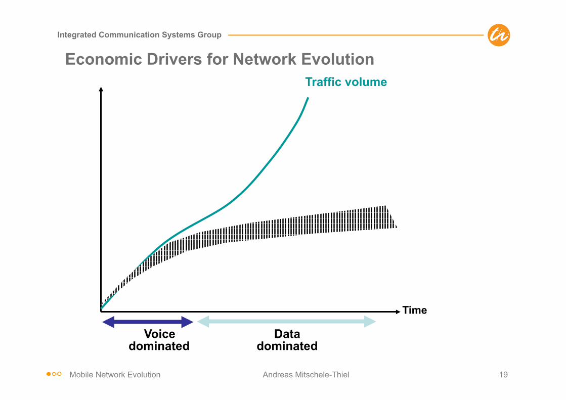
Economic Drivers for Network Evolution
Voice dominated
Data dominated
Traffic volume
Time
Profit
Network cost (existing technologies)
Network cost (LTE)
Decouple network cost from traffic volume!
Revenue

Mobile Network Evolution Andreas Mitschele-Thiel 20
Integrated Communication Systems Group
LTE Requirements and Performance Targets
Mobile Network Evolution Andreas Mitschele-Thiel 21
Integrated Communication Systems Group
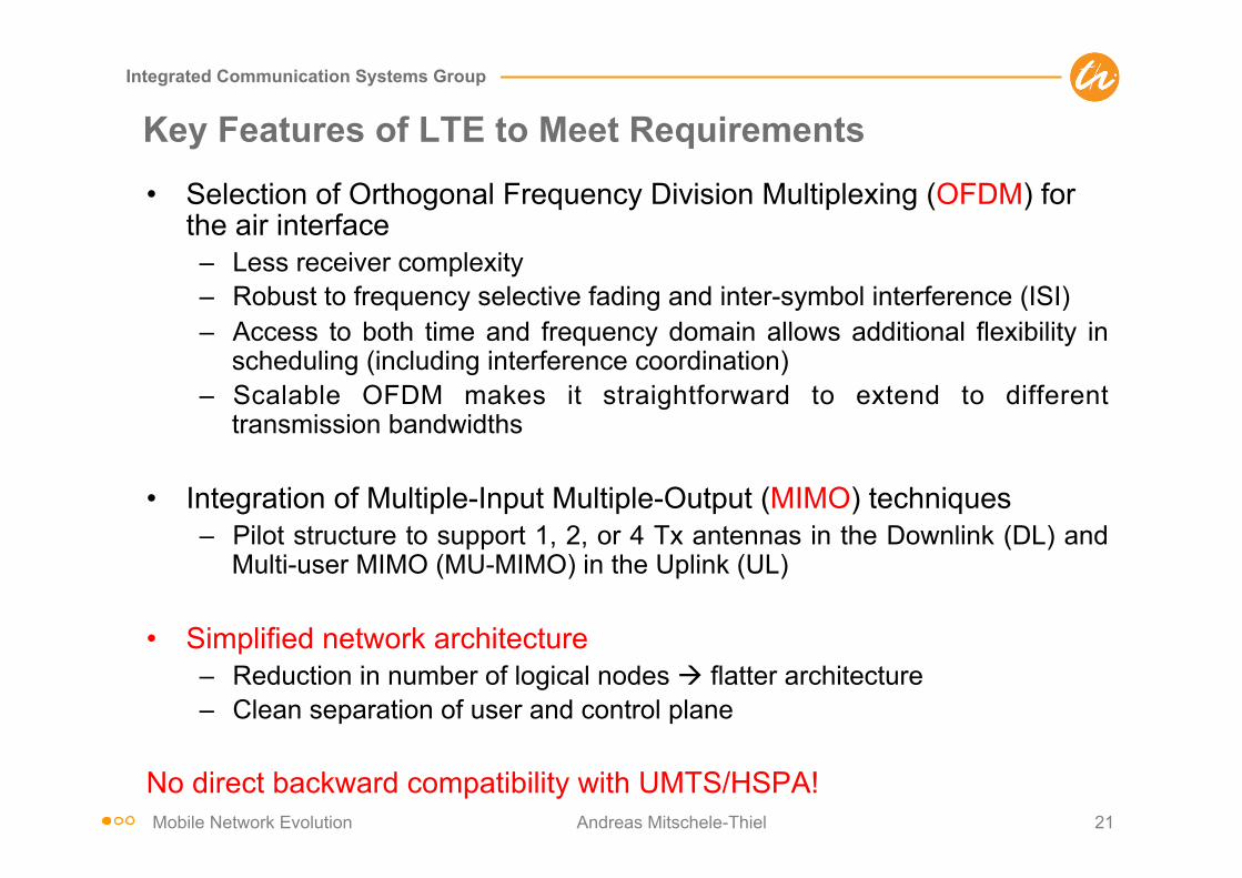
Key Features of LTE to Meet Requirements
• Selection of Orthogonal Frequency Division Multiplexing (OFDM) for the air interface – Less receiver complexity – Robust to frequency selective fading and inter-symbol interference (ISI) – Access to both time and frequency domain allows additional flexibility in
scheduling (including interference coordination) – Scalable OFDM makes it straightforward to extend to different
transmission bandwidths
• Integration of Multiple-Input Multiple-Output (MIMO) techniques – Pilot structure to support 1, 2, or 4 Tx antennas in the Downlink (DL) and
Multi-user MIMO (MU-MIMO) in the Uplink (UL)
• Simplified network architecture – Reduction in number of logical nodes à flatter architecture – Clean separation of user and control plane
No direct backward compatibility with UMTS/HSPA!
Mobile Network Evolution Andreas Mitschele-Thiel 22
Integrated Communication Systems Group
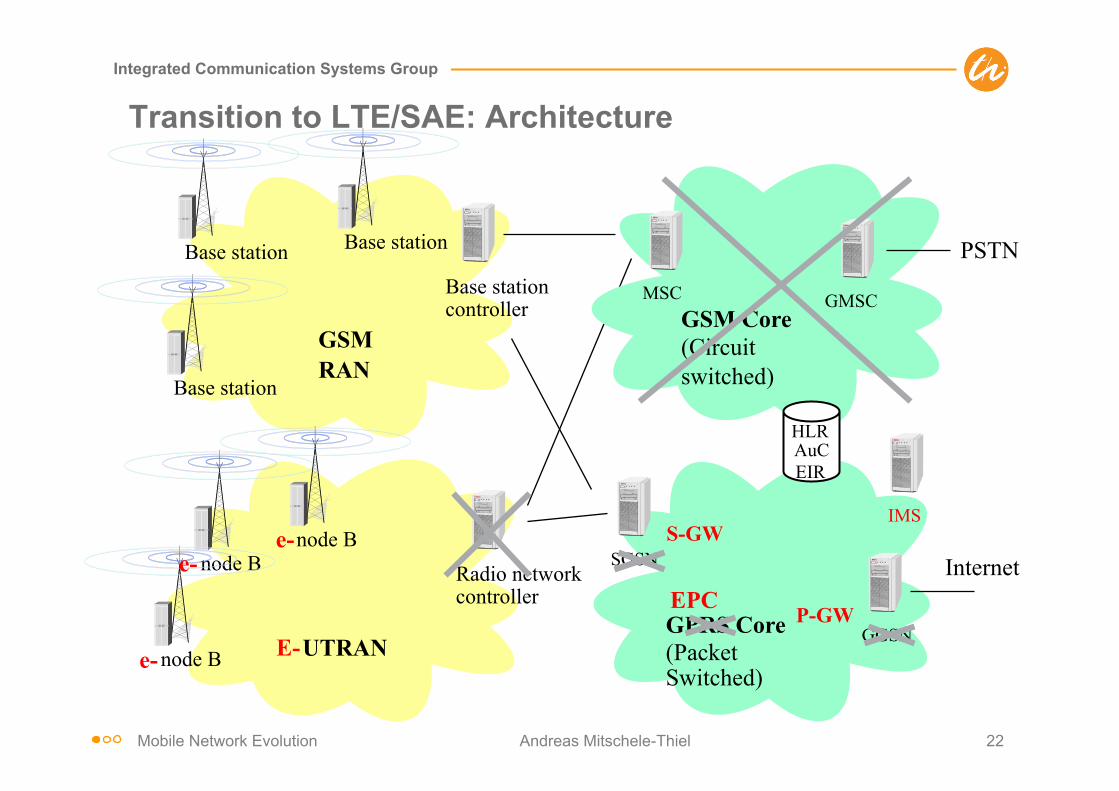
Transition to LTE/SAE: Architecture
GPRS Core (Packet Switched)
SGSN
GGSN
Internet
GSM RAN
Base station Base station controller
Base station
Base station
UTRAN
Radio network controller
node B node B
node B
MSC
PSTN
GSM Core (Circuit switched)
HLR AuC EIR
GMSC
E- e-
e- e- S-GW
P-GW
IMS
EPC

Mobile Network Evolution Andreas Mitschele-Thiel 23
Integrated Communication Systems Group
Network Simplification: From 3GPP to 3GPP LTE
• 3GPP architecture – 4 functional entities on the
control plane and user plane – 3 standardized user plane
and control plane interfaces
S-GW: Access Server Gateway MME: Mobility Management Entity eNodeB: Evolved NodeB
• 3GPP LTE architecture – 2 functional entities on the user
plane: eNodeB and S-GW – SGSN control plane functions =>
S-GW & MME – Less interfaces, some functions
will disappear • 4 layers into 2 layers
– Evolve GGSN à integrated S-GW
– Moving SGSN functionalities to S-GW
– RNC evolutions to RRM on a IP distributed network for enhancing mobility management
– Part of RNC mobility function being moved to S-GW & eNodeB
!"#$%&'()*+,- ./01+'2-%"3(-45'6'7#53'68%9'0-%":4,'05'3;% &*<=%>?@@
&'()*+,%$3;A63B342(3*0C%D+*;%EFGG%(*%EFGG%H#I
EFGG%2+453('4(J+'K%BJ04(3*026%'0(3(3'-%*0%(5'%4*0(+*6%A620'%201%J-'+%A620'E%-(2012+13L'1%J-'+%A620'%M%4*0(+*6%A620'%30('+B24'-
EFGG%H#I%2+453('4(J+'>%BJ04(3*026%'0(3(3'-%*0%(5'%J-'+%A620'C%'&*1'N%201%$7FO$F$&%4*0(+*6%A620'%BJ04(3*0-%$7FO%M%""I
H'--%30('+B24'-8%-*;'%BJ04(3*0-%)366%13-2AA'2+
K%62P'+-%30(*%>%62P'+-I<*6<'%FF$&% 30('Q+2('1%$7FO%"*<30Q%$F$&%BJ04(3*0263(3'-%(*%$7FO=%R&S%'<*6J(3*0-%(*%RR"%*0%2%TG%13-(+3UJ('1%0'()*+,%B*+%'0520430Q%;*U363(P%;202Q';'0(=G2+(%*B%R&S%;*U363(P%BJ04(3*0%U'30Q%;*<'1%(*%$7FO%M%'&*1'N
GGSN
SGSN
RNC
NodeB
ASGW
eNodeB
MMFGGSN
SGSN
RNC
NodeB
Control plane User plane
ASGW
eNodeB
MMF
S-GW
eNodeB
MME
Control plane User plane
$7FOC%$'+<30Q%F2(')2P""IC%"*U363(P%"202Q';'0(%I0(3(P
'&*1'NC%I<*6<'1%&*1'N

Mobile Network Evolution Andreas Mitschele-Thiel 24
Integrated Communication Systems Group
Evolved Packet System (EPS) Architecture
eNB
eNB
eNB
MME/S-GW MME/S-GW
X2
EPC E
-UTR
AN
S1
S1
S1 S1
S1 S1
X2
X2
EPC = Evolved Packet Core
Key elements of network architecture
– No more RNC – RNC layers/functionalities
moves in eNB – X2 interface for seamless
mobility (i.e. data/context forwarding) and interference management
Note: Standard only defines logical structure!
Mobile Network Evolution Andreas Mitschele-Thiel 25
Integrated Communication Systems Group
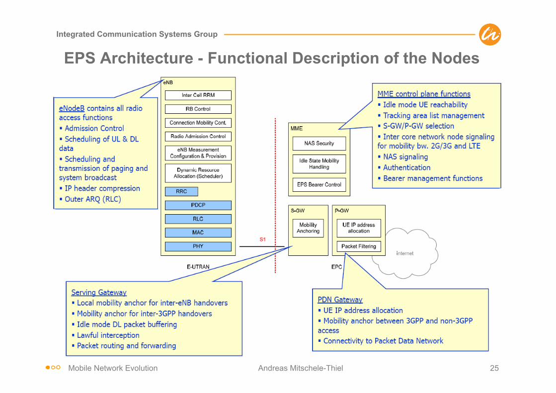
EPS Architecture - Functional Description of the Nodes

Mobile Network Evolution Andreas Mitschele-Thiel 26
Integrated Communication Systems Group
EPS Architecture - Control Plane Layout over S1
eNB
PHY
UE
PHY
MAC
RLC
MAC
MME
RLC
NAS NAS
RRC RRC
PDCP PDCP
UE eNode-B MME
RRC sub-layer performs: § Broadcasting § Paging § Connection Mgt § Radio bearer control § Mobility functions § UE measurement reporting & control
PDCP sub-layer performs: § Integrity protection & ciphering
NAS sub-layer performs: § Authentication § Security control § Idle mode mobility handling § Idle mode paging origination
Mobile Network Evolution Andreas Mitschele-Thiel 27
Integrated Communication Systems Group
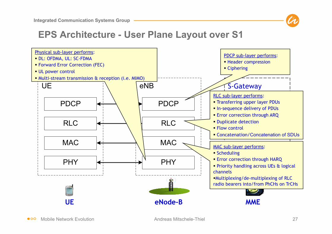
EPS Architecture - User Plane Layout over S1
eNB
PHY
UE
PHY
MAC
RLC
MAC
PDCPPDCP
RLC
S-Gateway RLC sub-layer performs: § Transferring upper layer PDUs § In-sequence delivery of PDUs § Error correction through ARQ § Duplicate detection § Flow control § Concatenation/Concatenation of SDUs
PDCP sub-layer performs: § Header compression § Ciphering
MAC sub-layer performs: § Scheduling § Error correction through HARQ § Priority handling across UEs & logical channels § Multiplexing/de-multiplexing of RLC radio bearers into/from PhCHs on TrCHs
Physical sub-layer performs: § DL: OFDMA, UL: SC-FDMA § Forward Error Correction (FEC) § UL power control § Multi-stream transmission & reception (i.e. MIMO)
UE eNode-B MME
Mobile Network Evolution Andreas Mitschele-Thiel 28
Integrated Communication Systems Group
LTE Key Features (Release 8)
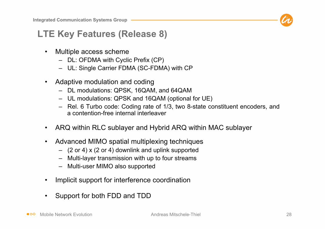
• Multiple access scheme – DL: OFDMA with Cyclic Prefix (CP) – UL: Single Carrier FDMA (SC-FDMA) with CP
• Adaptive modulation and coding – DL modulations: QPSK, 16QAM, and 64QAM – UL modulations: QPSK and 16QAM (optional for UE) – Rel. 6 Turbo code: Coding rate of 1/3, two 8-state constituent encoders, and
a contention-free internal interleaver
• ARQ within RLC sublayer and Hybrid ARQ within MAC sublayer
• Advanced MIMO spatial multiplexing techniques – (2 or 4) x (2 or 4) downlink and uplink supported – Multi-layer transmission with up to four streams – Multi-user MIMO also supported
• Implicit support for interference coordination
• Support for both FDD and TDD
Mobile Network Evolution Andreas Mitschele-Thiel 29
Integrated Communication Systems Group
Multi-antenna Solutions
IEEE Communications Magazine • April 200948
ple-input multiple-output [MIMO], as well asmulti-user MIMO) with up to four antennas, andbeamforming. Which of the schemes (or whichcombination of the schemes) to use depends onthe scenario (Fig. 5). In the uplink, both open-and closed-loop transmit-antenna selection aresupported as optional features.
LTE transmit diversity is based on so-calledspace-frequency block coding (SFBC), comple-mented with frequency-switched transmit diversi-ty (FSTD) in the case of four transmit antennas[1]. Transmit diversity is primarily intended forcommon downlink channels to provide addition-al diversity for transmissions for which channel-dependent scheduling is not possible. However,transmit diversity also can be applied to user-data transmission, for example, to voice-over-IP(VoIP), where the relatively low user-data ratesmay not justify the additional overhead associat-ed with channel-dependent scheduling.
In case of spatial multiplexing, multiple anten-nas at both the transmitter (base station) andthe receiver (terminal) side are used to providesimultaneous transmission of multiple, paralleldata streams, also known as layers, over a singleradio link, thereby significantly increasing thepeak data rates that can be provided over theradio link. As an example, with four base-stationtransmit antennas and a corresponding set of (atleast) four receive antennas at the terminal side,up to four data streams can be transmitted inparallel over the same radio link, effectivelyincreasing the data rate by a factor of four.
LTE multi-stream transmission is pre-coderbased. A number of transmission layers aremapped to up to four antennas by means of aprecoder matrix of size NA!NL, where the num-ber of layers NL, also known as the transmissionrank, is less than or equal to the number ofantennas NA. The transmission rank, as well asthe exact precoder matrix, can be selected by thenetwork, based on channel-status measurementsperformed and reported by the terminal, alsoknown as closed-loop spatial multiplexing.
In the case of spatial multiplexing, by select-ing rank-1 transmission, the precoder matrix,which then becomes an NA!1 precoder vector,performs a (single-layer) beamforming function.More specifically, this type of beamforming canbe referred to as codebook-based beamforming
as the beamforming can be done only accordingto a limited set of pre-defined beamforming(precoder) vectors.
In addition to the codebook-based beam-forming as a special case of the LTE spatial mul-tiplexing, LTE also supports more generalnon-codebook-based beamforming. In contrast tocodebook-based beamforming, in the case ofnon-codebook-based beamforming, the terminalmust make an estimate of the overall beam-formed channel. To enable this, LTE providesthe possibility for the transmission of user equip-ment (UE)-specific reference symbols, transmit-ted using the same beamforming as the userdata, and enabled for the terminal to estimatethe overall beamformed channel.
POWER CONTROL ANDINTER-CELL INTERFERENCE COORDINATION
LTE provides (intra-cell) orthogonality betweenusers in both uplink and downlink, that is, atleast in the ideal case, no interference betweentransmissions within the same cell but only inter-ference between cells. Hence, LTE performancein terms of spectrum efficiency and availabledata rates is, relatively speaking, more limited byinterference from other cells (inter-cell interfer-ence) compared to WCDMA/HSPA, especiallyfor users at the cell edge. Therefore, the meansto reduce or control the inter-cell interferencepotentially can provide substantial benefits toLTE performance, especially in terms of the ser-vice (data rates, etc.) that can be provided tousers at the cell edge.
Uplink power control is one of the mecha-nisms in LTE used for this purpose. It is used tocontrol not only the received signal strength inthe intended cell, but also to control the amountof interference in neighboring cells. LTE uplink-power control supports fractional path-loss com-pensation, implying that users close to the cellborder use relatively less transmit power, andthus generate relatively less interference toneighbor cells. However, LTE provides moreadvanced interference-handling schemes as well.
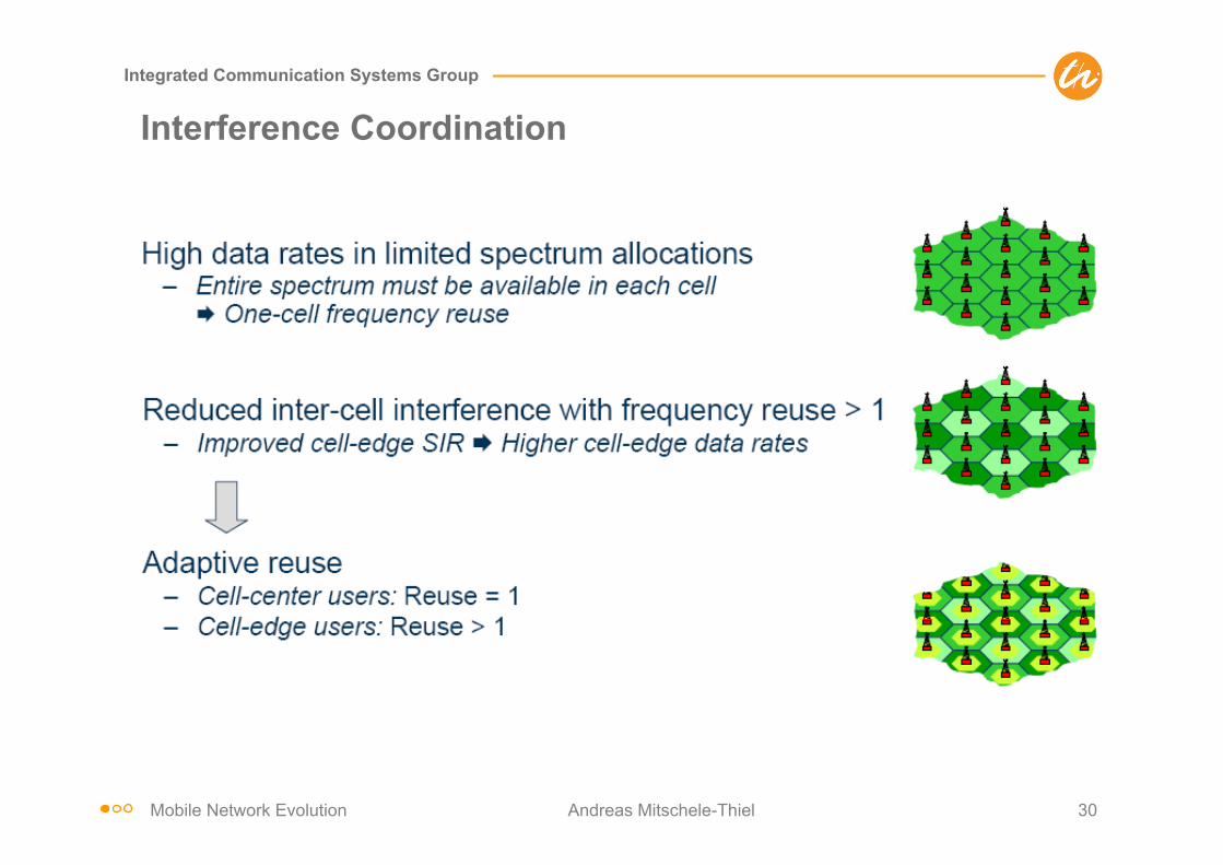
Inter-cell interference coordination (ICIC) isin essence a scheduling strategy used to limit theinter-cell interference. A simple method toimprove cell-edge data rates is to restrict theusage of parts of the bandwidth statically, forexample, through a reuse larger than one. Suchschemes improve the signal-to-interference ratiosof the used frequencies. However, the loss due toreduced bandwidth availability is typically largerthan the corresponding gain due to higher signal-to-interference ratio, leading to an overall loss ofefficiency. Therefore, the LTE standard providestools for dynamic inter-cell-interference coordina-tion of the scheduling in neighbor cells such thatcell-edge users in different cells preferably arescheduled on complementary parts of the spec-trum when required. Note that a major differencefrom static reuse schemes is that LTE still allowsfor the total available spectrum to be used in allcells. Bandwidth restrictions are applied onlywhen motivated by traffic and radio conditions.
Interference coordination can be applied toboth uplink and downlink, although with somefundamental differences between the two links. In
!!
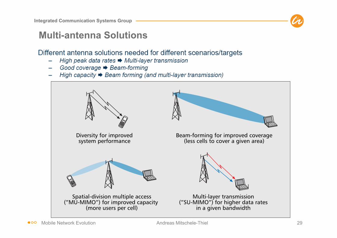
Figure 5. Multiple-antenna techniques in LTE.
Diversity for improvedsystem performance
Beam-forming for improved coverage(less cells to cover a given area)
Spatial-division multiple access(”MU-MIMO”) for improved capacity
(more users per cell)
Multi-layer transmission(”SU-MIMO”) for higher data rates
in a given bandwidth
PARKVALL LAYOUT 3/25/09 2:17 PM Page 48
Mobile Network Evolution Andreas Mitschele-Thiel 30
Integrated Communication Systems Group
Interference Coordination

Mobile Network Evolution Andreas Mitschele-Thiel 31
Integrated Communication Systems Group
Downlink Peak Rates
Assumptions: 64QAM, code rate =1, 1OFDM symbol for L1/L2, ignores subframes with P-BCH, SCH

Mobile Network Evolution Andreas Mitschele-Thiel 32
Integrated Communication Systems Group
Uplink Peak Rates
Assumptions: code rate =1, 2PRBs reserved for PUCCH (1 for 1.4MHz), no SRS, ignores subframes with PRACH, takes into account highest prime-factor restriction

Mobile Network Evolution Andreas Mitschele-Thiel 33
Integrated Communication Systems Group
Scheduling and Resource Allocation (1/2)
• LTE uses a scheduled, shared channel on both the uplink (UL-SCH) and the downlink (DL-SCH)
• Normally, there is no concept of an autonomous transmission; all transmissions in both uplink and downlink must be explicitly scheduled
• LTE allows "semi-persistent" (periodical) allocation of resources, e.g. for VoIP

Mobile Network Evolution Andreas Mitschele-Thiel 34
Integrated Communication Systems Group
Scheduling and Resource Allocation (2/2)
• Basic unit of allocation is called a Resource Block (RB) – 12 subcarriers in frequency (= 180 kHz) – 1 sub-frame in time (= 1 ms, = 14 OFDM symbols) – Multiple resource blocks can be allocated to a user in a given subframe
• The total number of RBs available depends on the operating bandwidth

Mobile Network Evolution Andreas Mitschele-Thiel 35
Integrated Communication Systems Group
LTE Handover (1/2)
• LTE uses UE-assisted network controlled handover – UE reports measurements; network decides when to handover and to which
cell – Relies on UE to detect neighbor cells à no need to maintain and broadcast
neighbor lists - Allows "plug-and-play" capability; saves BCH resources
– For search and measurement of inter-frequency neighboring cells only carrier frequency need to be indicated
• X2 interface used for handover preparation and data forwarding – Target eNB prepares handover by sending required information to UE
transparently through source eNB as part of the Handover Request Acknowledge message - New configuration information needed from system broadcast - Accelerates handover as UE does not need to read BCH on target cell
– Buffered and new data is transferred from source to target eNB until path switch à prevents data loss
– UE uses contention-free random access to accelerate handover
Mobile Network Evolution Andreas Mitschele-Thiel 36
Integrated Communication Systems Group
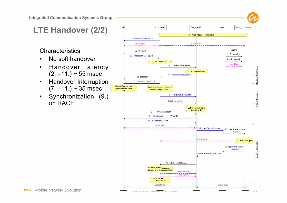
LTE Handover (2/2)
Characteristics • No soft handover • Handover latency
(2. –11.) ~ 55 msec • Handover Interruption
(7. –11.) ~ 35 msec • Synchronization (9.)
on RACH

Mobile Network Evolution Andreas Mitschele-Thiel 37
Integrated Communication Systems Group
Tracking Area
Tracking Area Identifier (TAI) sent over Broadcast Channel BCH Tracking Areas can be shared by multiple MMEs
Mobile Network Evolution Andreas Mitschele-Thiel 38
Integrated Communication Systems Group
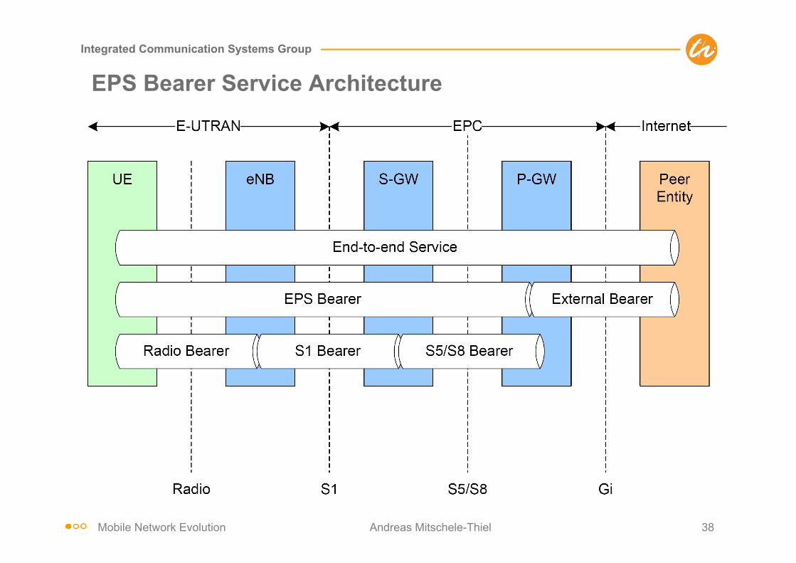
EPS Bearer Service Architecture
Mobile Network Evolution Andreas Mitschele-Thiel 39
Integrated Communication Systems Group
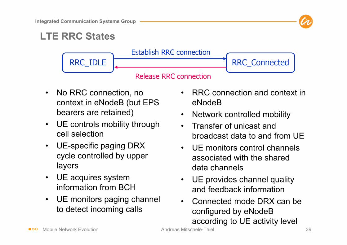
LTE RRC States
• No RRC connection, no context in eNodeB (but EPS bearers are retained)
• UE controls mobility through cell selection
• UE-specific paging DRX cycle controlled by upper layers
• UE acquires system information from BCH
• UE monitors paging channel to detect incoming calls
• RRC connection and context in eNodeB
• Network controlled mobility • Transfer of unicast and
broadcast data to and from UE • UE monitors control channels
associated with the shared data channels
• UE provides channel quality and feedback information
• Connected mode DRX can be configured by eNodeB according to UE activity level
Mobile Network Evolution Andreas Mitschele-Thiel 40
Integrated Communication Systems Group
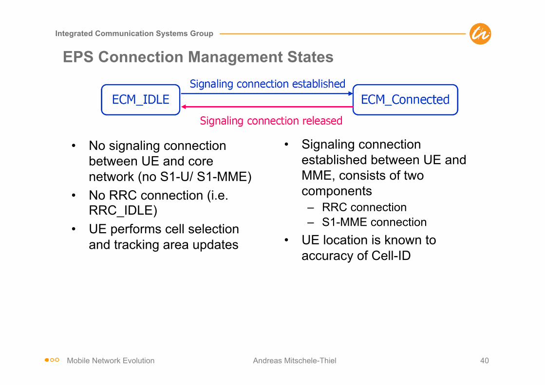
EPS Connection Management States
• No signaling connection between UE and core network (no S1-U/ S1-MME)
• No RRC connection (i.e. RRC_IDLE)
• UE performs cell selection and tracking area updates
• Signaling connection established between UE and MME, consists of two components – RRC connection – S1-MME connection
• UE location is known to accuracy of Cell-ID
Mobile Network Evolution Andreas Mitschele-Thiel 41
Integrated Communication Systems Group
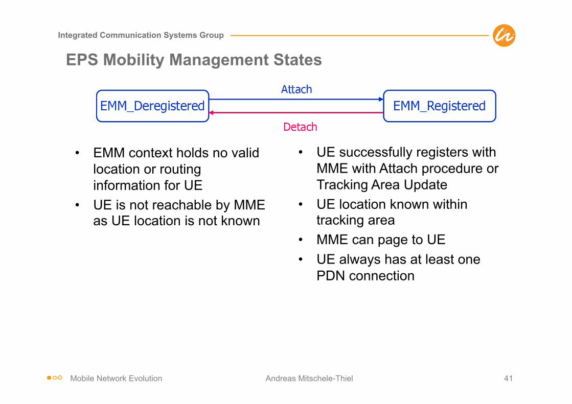
EPS Mobility Management States
• EMM context holds no valid location or routing information for UE
• UE is not reachable by MME as UE location is not known
• UE successfully registers with MME with Attach procedure or Tracking Area Update
• UE location known within tracking area
• MME can page to UE • UE always has at least one
PDN connection
Mobile Network Evolution Andreas Mitschele-Thiel 42
Integrated Communication Systems Group
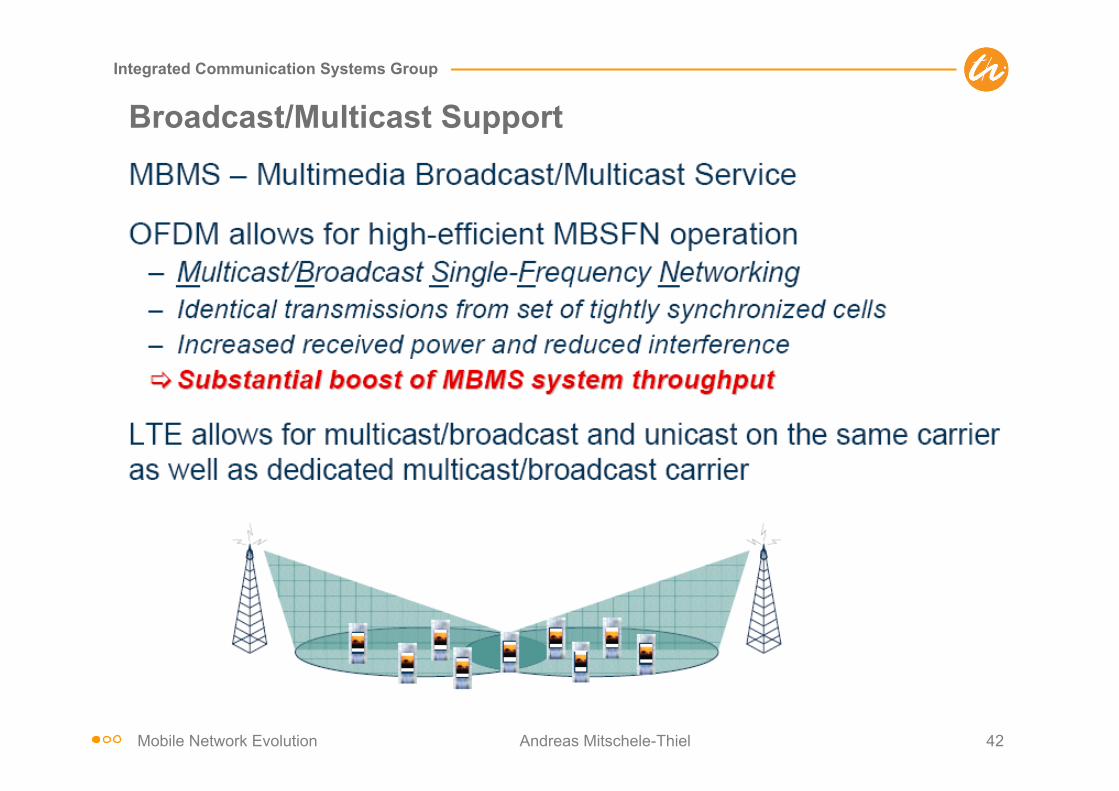
Broadcast/Multicast Support

Mobile Network Evolution Andreas Mitschele-Thiel 43
Integrated Communication Systems Group
LTE vs. WiMax vs. 3GPP2
IMS
• Authenticator • Paging Controller • Page buffering
WiMAX
Access Point
CAP-C FA/Router
• Handover Control • Radio Resource
Management • ARQ/MAC/PHY • L2 Ciphering • Classification/
ROHC
E-Node B
MME Serv GW
HSS
IMS
• Authenticator • Paging Controller • Session setup
• Handover Control • Radio Resource
Management • ARQ/MAC/PHY • L2 Ciphering • ROHC
3GPP/LTE
PDN GW
• Local mobility • Page buffering
• Local mobility • Session setup • Bearer mapping
eBTS
SRNC Access GW
AAA
IMS
• Authenticator • Paging
Controller
• Handover Control • Radio Resource
Management • ARQ/MAC/PHY • L2 Ciphering • ROHC
3GPP2/UMB
HA
PCRF
IETF-centric architecture IETF-centric architecture IETF-friendly, but still some flavor of UMTS/
GPRS – GTP, etc
• Bearer mapping
PCRF
• Local mobility • Session setup • Bearer mapping
AAA HA
Mobile Network Evolution Andreas Mitschele-Thiel 44
Integrated Communication Systems Group
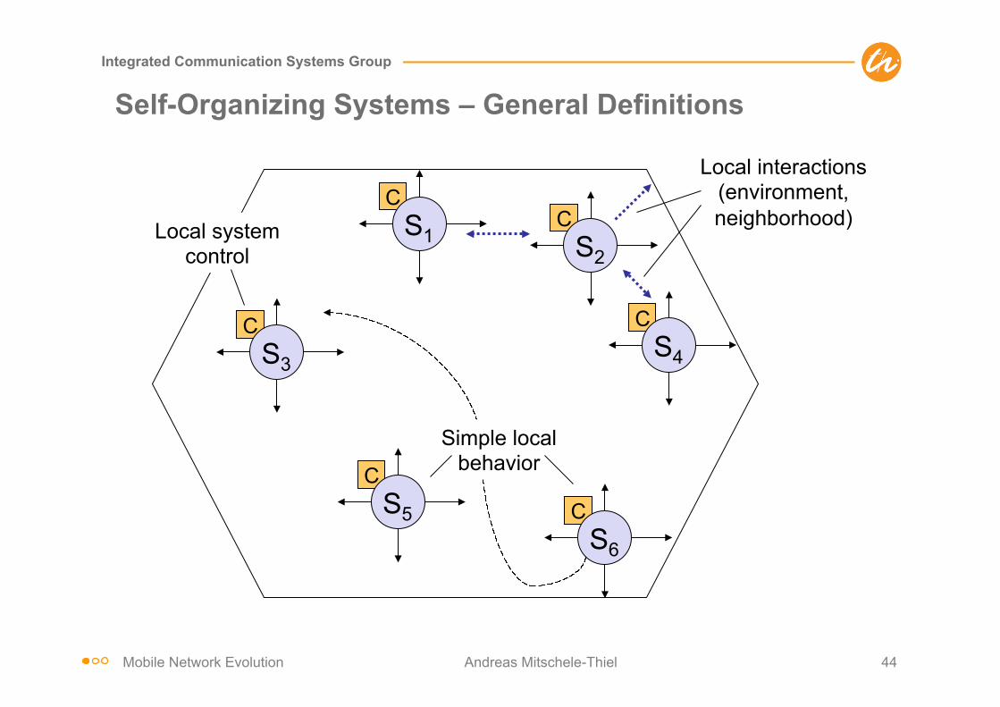
C S3
C S5
C S1
C S4
C S2
Local interactions (environment, neighborhood) Local system
control
Simple local behavior
C S6
Self-Organizing Systems – General Definitions

Mobile Network Evolution Andreas Mitschele-Thiel 45
Integrated Communication Systems Group
Property Description
No central control No global control system No global information Subsystems perform completely autonomous
Emerging structures Global behavior or functioning of the system emerges in form of observable pattern or structures
Resulting complexity Even if the individual subsystems can be simple as well as their basic rules, the resulting overall system becomes complex and often unpredictable
High scalability
No performance degradation if more subsystems are added to the system System performs as requested regardless of the number of subsystems
Self-Organizing Systems – General Properties

Mobile Network Evolution Andreas Mitschele-Thiel 46
Integrated Communication Systems Group
Self-organization in LTE
Motivation and drivers • Multitude of re-configurable parameters, e.g. transmit powers,
control channel powers, handover parameters etc. • Huge number of eNBs expected with the introduction of Home
eNB concept • Home eNB
– Small Coverage Area – Small number of users per cell – May be switched off by user – Not physically accessible for operators
• Self-organization (SO) is driven by operators to reduce Operational Expenses (OPEX)
• Main push of Self-Optimizing Networks (SON) by NGMN alliance (www.ngmn.org)
Mobile Network Evolution Andreas Mitschele-Thiel 47
Integrated Communication Systems Group
SO Functionality in LTE (1/5)
SO functionality includes • Self-configuration • Self-optimization • Self-healing and self-repair
Mobile Network Evolution Andreas Mitschele-Thiel 48
Integrated Communication Systems Group
SO Functionality in LTE (2/5)
Self-Configuration • Objective is to have plug-n-play enabled nodes • Works in pre-operational state, which starts when the node is
powered up and has backbone connectivity until the RF transmitter is switched on
• Automatic installation procedures for newly deployed nodes • Automatic creation of the logical associations (interfaces) with the
network and establishment of the necessary security contexts • Download of configuration files from a configuration server • Performing a self-test to determine if everything is working as
intended • Finally, switching to active service

Mobile Network Evolution Andreas Mitschele-Thiel 49
Integrated Communication Systems Group
SO Functionality in LTE (3/5)
Self-optimization • Uses UE & eNB measurements and performance statistics to
auto-tune the network • Works in operational state, which starts when the RF interface is
switched on

Mobile Network Evolution Andreas Mitschele-Thiel 50
Integrated Communication Systems Group
SO Functionality in LTE (4/5)
Self-optimization process includes • Neighbor list optimization
– Reconfigures the neighbor list to have the minimum set of cells necessary for handover
• Coverage and capacity optimization – Maximizes the system capacity while ensuring an appropriate
overlapping area between the adjacent cells • Mobility robustness optimization
– Adjusts the handover thresholds to avoid unnecessary handovers • Mobility load balancing optimization
– Automatically handover some UEs at the edge of a congested cell to neighboring less congested cells
• Energy Saving – Autonomously switching off some of the resources or the complete
node during the times of low network demand

Mobile Network Evolution Andreas Mitschele-Thiel 51
Integrated Communication Systems Group
SO Functionality in LTE (5/5)
Self-healing and self-repair • Detects equipment faults, identifies the root causes and takes
recovery actions such as – Reducing transmit power in case of temperature alarm – Fallback to the previous software version – Switching to backup units
• If the fault can not be resolved locally by the above measures, the affected cell and the neighboring cells take cooperative actions to minimize QoS degradation
• Results in a reduced failure recovery time and a more efficient allocation of maintenance personnel
Mobile Network Evolution Andreas Mitschele-Thiel 52
Integrated Communication Systems Group
SON Architecture (1/4)
• Based on the location of SO functionality three architectural approaches are possible – Centralized – Distributed – Hybrid
Mobile Network Evolution Andreas Mitschele-Thiel 53
Integrated Communication Systems Group
SON Architecture (2/4)
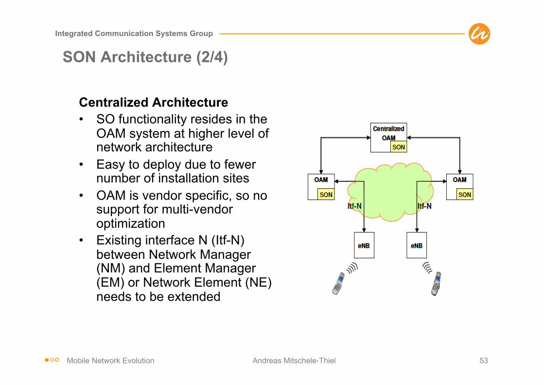
Centralized Architecture • SO functionality resides in the
OAM system at higher level of network architecture
• Easy to deploy due to fewer number of installation sites
• OAM is vendor specific, so no support for multi-vendor optimization
• Existing interface N (Itf-N) between Network Manager (NM) and Element Manager (EM) or Network Element (NE) needs to be extended

Mobile Network Evolution Andreas Mitschele-Thiel 54
Integrated Communication Systems Group
SON Architecture (3/4)
Distributed Architecture • SO functionality resides in the
eNB at the lower level of network architecture
• Difficult to deploy because of large number of installation sites
• Difficult to perform complex optimizations involving large number of eNBs
• Better performance for less complex optimizations involving a small number of eNBs
• X2 interface between the eNBs needs to be extended
Mobile Network Evolution Andreas Mitschele-Thiel 55
Integrated Communication Systems Group
SON Architecture (4/4)
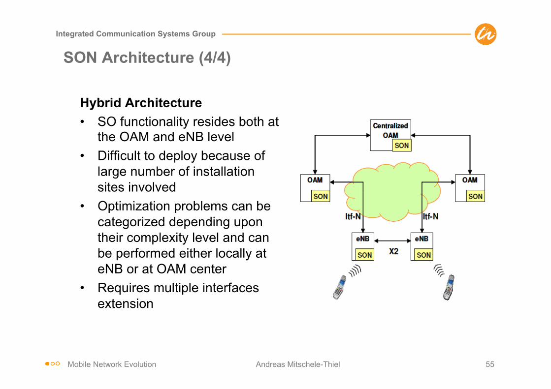
Hybrid Architecture • SO functionality resides both at
the OAM and eNB level • Difficult to deploy because of
large number of installation sites involved
• Optimization problems can be categorized depending upon their complexity level and can be performed either locally at eNB or at OAM center
• Requires multiple interfaces extension

Mobile Network Evolution Andreas Mitschele-Thiel 56
Integrated Communication Systems Group
Conclusions
• LTE is a new air interface with no backward compatibility to WCDMA – Combination of OFDM, MIMO and Higher-Order Modulation
• SAE/EPS realizes a flatter IP-based network architecture with less complexity
– eNodeB, S-GW, P-GW • Some procedures/protocols are being reused from UMTS
– Protocol stack – Concept of Logical, Transport and Physical Channels
• Complexity is significantly reduced – Reduced UE state space – Most transmission uses shared channels
• LTE standard (Rel. 8) is stable – Enhancements are discussed for Rel. 10 under LTE+
- Support of wider spectrum bandwidth (up to 100 MHz) - Spatial multiplexing in UL and DL - Beamforming and Higher-order MIMO in DL - Coordinated multipoint transmission and reception - Repeater (L1) and relaying (L3) functionality

Mobile Network Evolution Andreas Mitschele-Thiel 57
Integrated Communication Systems Group
References
LTE/SAE • A. Toskala et al, “UTRAN Long-Term Evolution,” Chapter 16 in Holma/ Toskala: WCDMA for UMTS, Wiley
2007 • E. Dahlman et al, “3G Evolution, HSPA and LTE for Mobile Broadband,” Elsevier Journal, 2007 • Special Issue on LTE/ WIMAX, Nachrichtentechnische Zeitung, pp. 12–24, 1/2007 • 3rd Generation Partnership Project Long Term Evolution (LTE), official website:
http://www.3gpp.org/Highlights/LTE/LTE.htm • Technical Paper, “UTRA-UTRAN Long Term Evolution (LTE) and 3GPP System Architecture Evolution (SAE)”,
last update October 2006, available at: ftp://ftp.3gpp.org/Inbox/2008_web_files/LTA_Paper.pdf Standards • TS 36.xxx series, RAN Aspects • TS 36.300, “E-UTRAN; Overall description; Stage 2” • TR 25.912, “Feasibility study for evolved Universal Terrestrial Radio Access (UTRA) and Universal Terrestrial
Radio Access Network (UTRAN)” • TR 25.814, “Physical layer aspect for evolved UTRA” • TR 23.882, “3GPP System Architecture Evolution: Report on Technical Options and Conclusions”
Self-organizing networks and LTE • Self-organizing networks and LTE, http://www.lightreading.com/document.asp?doc_id=158441 • NGMN Recommendation on SON and O&M Requirements, Dec. 5, 2008, NGMN, http://www.ngmn.org/
uploads/media/NGMN_Recommendation_on_SON_and_O_M_Requirements.pdf
Mobile Network Evolution Andreas Mitschele-Thiel 58
Integrated Communication Systems Group
Abbreviations
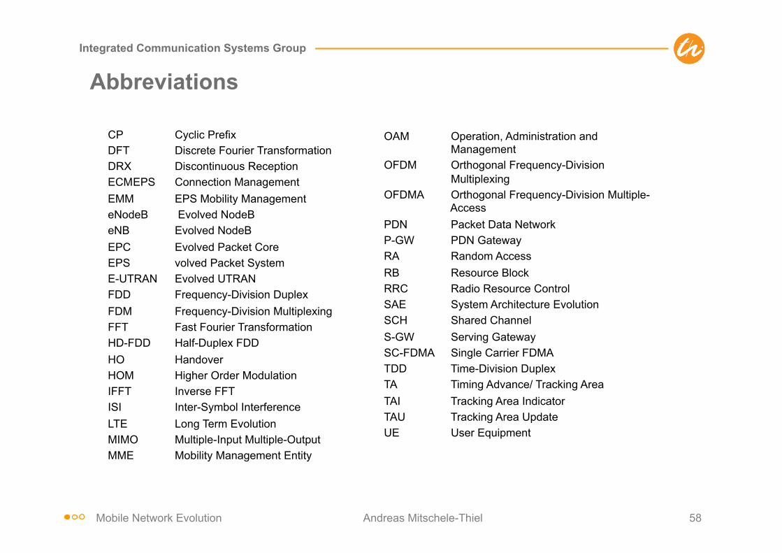
CP Cyclic Prefix DFT Discrete Fourier Transformation DRX Discontinuous Reception ECM EPS Connection Management EMM EPS Mobility Management eNodeB Evolved NodeB eNB Evolved NodeB EPC Evolved Packet Core EPS volved Packet System E-UTRAN Evolved UTRAN FDD Frequency-Division Duplex FDM Frequency-Division Multiplexing FFT Fast Fourier Transformation HD-FDD Half-Duplex FDD HO Handover HOM Higher Order Modulation IFFT Inverse FFT ISI Inter-Symbol Interference LTE Long Term Evolution MIMO Multiple-Input Multiple-Output MME Mobility Management Entity
OAM Operation, Administration and Management
OFDM Orthogonal Frequency-Division Multiplexing
OFDMA Orthogonal Frequency-Division Multiple- Access
PDN Packet Data Network P-GW PDN Gateway RA Random Access RB Resource Block RRC Radio Resource Control SAE System Architecture Evolution SCH Shared Channel S-GW Serving Gateway SC-FDMA Single Carrier FDMA TDD Time-Division Duplex TA Timing Advance/ Tracking Area TAI Tracking Area Indicator TAU Tracking Area Update UE User Equipment