mobile digital video recorder - hikvision€¦ · mobile digital video recorder user manual 2...
TRANSCRIPT
Mobile Digital Video Recorder
User Manual UD.6L0204D1113A01
Mobile Digital Video Recorder User Manual
1
User Manual
COPYRIGHT ©2015 Hangzhou Hikvision Digital Technology Co., Ltd.
ALL RIGHTS RESERVED.
Any and all information, including, among others, wordings, pictures, graphs are the properties of Hangzhou Hikvision
Digital Technology Co., Ltd. or its subsidiaries (hereinafter referred to be “Hikvision”). This user manual (hereinafter
referred to be “the Manual”) cannot be reproduced, changed, translated, or distributed, partially or wholly, by any means,
without the prior written permission of Hikvision. Unless otherwise stipulated, Hikvision does not make any warranties,
guarantees or representations, express or implied, regarding to the Manual.
About this Manual
This Manual is applicable to Mobile Digital Video Recorder.
The Manual includes instructions for using and managing the product. Pictures, charts, images and all other information
hereinafter are for description and explanation only. The information contained in the Manual is subject to change, without
notice, due to firmware updates or other reasons. Please find the latest version in the company website
(http://overseas.hikvision.com/en/).
Please use this user manual under the guidance of professionals.
Trademarks Acknowledgement
and other Hikvision’s trademarks and logos are the properties of Hikvision in various jurisdictions. Other
trademarks and logos mentioned below are the properties of their respective owners.
Legal Disclaimer
TO THE MAXIMUM EXTENT PERMITTED BY APPLICABLE LAW, THE PRODUCT DESCRIBED, WITH ITS
HARDWARE, SOFTWARE AND FIRMWARE, IS PROVIDED “AS IS”, WITH ALL FAULTS AND ERRORS, AND
HIKVISION MAKES NO WARRANTIES, EXPRESS OR IMPLIED, INCLUDING WITHOUT LIMITATION,
MERCHANTABILITY, SATISFACTORY QUALITY, FITNESS FOR A PARTICULAR PURPOSE, AND
NON-INFRINGEMENT OF THIRD PARTY. IN NO EVENT WILL HIKVISION, ITS DIRECTORS, OFFICERS,
EMPLOYEES, OR AGENTS BE LIABLE TO YOU FOR ANY SPECIAL, CONSEQUENTIAL, INCIDENTAL, OR
INDIRECT DAMAGES, INCLUDING, AMONG OTHERS, DAMAGES FOR LOSS OF BUSINESS PROFITS,
BUSINESS INTERRUPTION, OR LOSS OF DATA OR DOCUMENTATION, IN CONNECTION WITH THE USE OF
THIS PRODUCT, EVEN IF HIKVISION HAS BEEN ADVISED OF THE POSSIBILITY OF SUCH DAMAGES.
REGARDING TO THE PRODUCT WITH INTERNET ACCESS, THE USE OF PRODUCT SHALL BE WHOLLY AT
YOUR OWN RISKS. HIKVISION SHALL NOT TAKE ANY RESPONSIBILITES FOR ABNORMAL OPERATION,
PRIVACY LEAKAGE OR OTHER DAMAGES RESULTING FROM CYBER ATTACK, HACKER ATTACK, VIRUS
INSPECTION, OR OTHER INTERNET SECURITY RISKS; HOWEVER, HIKVISION WILL PROVIDE TIMELY
TECHNICAL SUPPORT IF REQUIRED.
SURVEILLANCE LAWS VARY BY JURISDICTION. PLEASE CHECK ALL RELEVANT LAWS IN YOUR
JURISDICTION BEFORE USING THIS PRODUCT IN ORDER TO ENSURE THAT YOUR USE CONFORMS THE
APPLICABLE LAW. HIKVISION SHALL NOT BE LIABLE IN THE EVENT THAT THIS PRODUCT IS USED WITH
ILLEGITIMATE PURPOSES.
IN THE EVENT OF ANY CONFLICTS BETWEEN THIS MANUAL AND THE APPLICABLE LAW, THE LATER
PREVAILS.
Mobile Digital Video Recorder User Manual
2
Regulatory Information
FCC Information
Please take attention that changes or modification not expressly approved by the party responsible for compliance could
void the user’s authority to operate the equipment.
Note: This product has been tested and found to comply with the limits for a Class B digital device, pursuant to Part 15 of
the FCC Rules. These limits are designed to provide reasonable protection against harmful interference in a residential
installation. This product generates, uses, and can radiate radio frequency energy and, if not installed and used in accordance
with the instructions, may cause harmful interference to radio communications. However, there is no guarantee that
interference will not occur in a particular installation. If this product does cause harmful interference to radio or television
reception, which can be determined by turning the equipment off and on, the user is encouraged to try to correct the
interference by one or more of the following measures:
—Reorient or relocate the receiving antenna.
—Increase the separation between the equipment and receiver.
—Connect the equipment into an outlet on a circuit different from that to which the receiver is connected.
—Consult the dealer or an experienced radio/TV technician for help.
FCC Conditions
This device complies with part 15 of the FCC Rules. Operation is subject to the following two conditions:
1. This device may not cause harmful interference.
2. This device must accept any interference received, including interference that may cause undesired operation.
EU Conformity Statement
This product and - if applicable - the supplied accessories too are marked with "CE" and comply therefore with
the applicable harmonized European standards listed under the EMC Directive 2004/108/EC, the RoHS
Directive 2011/65/EU, the R&TTE Directive 1999/5/EC.
2012/19/EU (WEEE directive): Products marked with this symbol cannot be disposed of as unsorted municipal
waste in the European Union. For proper recycling, return this product to your local supplier upon the purchase
of equivalent new equipment, or dispose of it at designated collection points. For more information see:
www.recyclethis.info
2006/66/EC (battery directive): This product contains a battery that cannot be disposed of as unsorted municipal
waste in the European Union. See the product documentation for specific battery information. The battery is
marked with this symbol, which may include lettering to indicate cadmium (Cd), lead (Pb), or mercury (Hg).
For proper recycling, return the battery to your supplier or to a designated collection point. For more information see:
www.recyclethis.info
Industry Canada ICES-003 Compliance
This device meets the CAN ICES-3 (B)/NMB-3(B) standards requirements.
This device complies with Industry Canada licence-exempt RSS standard(s). Operation is subject to the following two
conditions:
(1) this device may not cause interference, and
(2) this device must accept any interference, including interference that may cause undesired operation of the device.
Mobile Digital Video Recorder User Manual
3
Le présent appareil est conforme aux CNR d'Industrie Canada applicables aux appareils radioexempts de licence.
L'exploitation est autorisée aux deux conditions suivantes :
(1) l'appareil ne doit pas produire de brouillage, et
(2) l'utilisateur de l'appareil doit accepter tout brouillage radioélectrique subi, même si le brouillage est susceptible d'en
compromettre le fonctionnement.
Under Industry Canada regulations, this radio transmitter may only operate using an antenna of a type and maximum (or
lesser) gain approved for the transmitter by Industry Canada. To reduce potential radio interference to other users, the
antenna type and its gain should be so chosen that the equivalent isotropically radiated power (e.i.r.p.) is not more than that
necessary for successful communication.
Conformément à la réglementation d'Industrie Canada, le présent émetteur radio peut
fonctionner avec une antenne d'un type et d'un gain maximal (ou inférieur) approuvé pour l'émetteur par Industrie Canada.
Dans le but de réduire les risques de brouillage radioélectrique à l'intention des autres utilisateurs, il faut choisir le type
d'antenne et son gain de sorte que la puissance isotrope rayonnée équivalente (p.i.r.e.) ne dépasse pas l'intensité nécessaire à
l'établissement d'une communication satisfaisante.
Mobile Digital Video Recorder User Manual
4
Safety Instruction
These instructions are intended to ensure that user can use the product correctly to avoid danger or property loss.
The precaution measure is divided into “Warnings” and “Cautions”
Warnings: Serious injury or death may occur if any of the warnings are neglected. Cautions: Injury or equipment damage may occur if any of the cautions are neglected.
Warnings
● Proper configuration of all passwords and other security settings is the responsibility of the installer and/or end-user.
● In the use of the product, you must be in strict compliance with the electrical safety regulations of the nation and region.
Please refer to technical specifications for detailed information.
● Input voltage should meet both the SELV (Safety Extra Low Voltage) and the Limited Power Source with +8 to +36
VDC according to the IEC60950-1 standard. Please refer to technical specifications for detailed information.
● Do not connect several devices to one power adapter as adapter overload may cause over-heating or a fire hazard.
● Please make sure that the plug is firmly connected to the power socket.
● If smoke, odor or noise rise from the device, turn off the power at once and unplug the power cable, and then please
contact the service center.
Warnings Follow these safeguards to
prevent serious injury or death.
Cautions Follow these precautions to
prevent potential injury or material
damage.
Mobile Digital Video Recorder User Manual
5
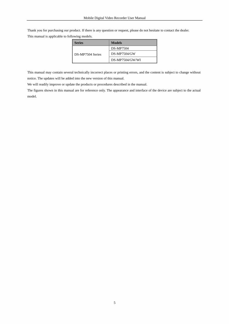
Thank you for purchasing our product. If there is any question or request, please do not hesitate to contact the dealer.
This manual is applicable to following models.
Series Models
DS-MP7504 Series
DS-MP7504
DS-MP7504/GW
DS-MP7504/GW/WI
This manual may contain several technically incorrect places or printing errors, and the content is subject to change without
notice. The updates will be added into the new version of this manual.
We will readily improve or update the products or procedures described in the manual.
The figures shown in this manual are for reference only. The appearance and interface of the device are subject to the actual
model.
Mobile Digital Video Recorder User Manual
6
Safety Instructions
Read, keep and follow these instructions.
Professional automobile assembly manufacturers or automakers are required for the system installation. And place the
device at a well-ventilated position inside the automobile.
Please make yourself be familiar with the power connection before installation.
Install antennas of wireless networks and satellite positioning in place with good signal and away from lightning,
avoiding the coverage or shielding of other objects. Keep the master and slave antennas upright in a distance of at least
20cm if both of them are installed.
The system is made of sophisticated electronics and do not disassemble the device by yourself.
Contact the qualified technician from Hikvision or authorized dealer if there is any question or request.
Mobile Digital Video Recorder User Manual
7
Product Key Features
General
User-friendly GUI providing easy and flexible operations.
Each channel supporting up to 4CIF resolution with high-efficient and flexible H.264 encoding technology.
Two HDDs/SSDs are connectable.
Hard disk box with fan and USB interface supporting intelligent temperature control and data export.
Built-in 3G (WCDMA) and WI-FI modules providing flexible data transmission solutions.
Power-off protection avoiding key data from loss.
Backup recording on HDD/SSD ensures the completeness of video files; Event triggered recording can be stored on
the HDD/SSD simultaneously to protect the key data.
Built-in GNSS (Global Navigation Satellite System) module precisely positioning the vehicle via the satellite and
recording the location information in the stream.
Information collection interfaces collecting driving information such as left/right turn, braking, backing up, etc.
Multiple extension interfaces supporting display terminal of alarm and status, external G-sensor, etc.
Specialized aviation connectors ensuring signal stability.
Ignition startup, Delay (0 to 6h) shutdown and 24-hour scheduled startup/shutdown.
Wide-range power input (+8 to +36 VDC).
Tensile aluminum chassis well adaptable to working environment.
Software-based firewall supported.
Local Monitoring
1/4-division live view and adjustable display sequence of screens.
Shielding designated live view channel.
Motion detection, tamper-proof, video exception alarm and video loss alarm.
Privacy mask.
Hard Disk Management
Supports two HDDs/SSDs with 64G capacity for each.
Record and Playback
Cycle recording and non-cycle recording supported.
Three types of compression parameters including main stream (normal), main stream (event) and sub-stream.
Multiple recording types: normal, alarm, motion, motion | alarm, motion & alarm.
Up to 8 time periods configurable for different recording types.
Pre-record and post-record for motion or alarm triggered recording.
Search and play back record files by camera No., recording type, start/end time, etc.
Supporting pause, fast forward, slow forward, skip forward, skip backward and mute when playback.
Backup
Export video data by USB device.
Export video data by pluggable hard disk.
Management and maintenance of backup devices.
Mobile Digital Video Recorder User Manual
8
Alarm and Exception
Management of alarm input/output.
Management of video loss alarm, motion detection alarm, video tampering alarm.
Configurable arming schedule of alarm input/output.
Alarm for video loss, motion detection, video tampering, video signal exception, video input/output standard mismatch,
illegal login, network disconnected, IP confliction, hard disk error, and hard disk full.
Multiple alarm linkage actions including full screen monitoring, audible warning and alarm output. Motion detection
and alarm can trigger recording and full screen monitoring. Exception can trigger audible warning and alarm output.
Automatic restore when system is abnormal.
Supporting alarm and status display terminal.
Other Local Functions
Two-level user management; admin user is allowed to configure the parameters and create many operators.
Supporting record and search the logs of operation, alarm, exceptions and information.
Upgrade system via USB, network or RS-232 interface.
Import/export of device configuration file.
Network Functions
1 self-adaptive 10M/100M network interface.
WCDMA supported.
Wi-Fi supported.
Remote configuration and operation by iVMS platform.
TCP/IP, DHCP, DNS, NTP, and SADP supported.
Remote search, playback, download of record files.
Remote parameters setup; remote import/export of device parameters.
Remote viewing of the device status, system logs and alarm status.
Remote hard disk formatting, program upgrading and system restart.
RS-232, RS-485 transparent channel transmission.
Development Scalability
SDK for Windows and Linux system.
Development support and training for application system.
The Wi-Fi function is only supported by the “/WI” devices.
The 3G dialing function is only supported by the “/GW” devices.
Mobile Digital Video Recorder User Manual
9
TABLE OF CONTENTS Safety Instructions .................................................................................................................................................. 6
Product Key Features .............................................................................................................................................. 7
Chapter 1 Introduction ...................................................................................................................................... 11
1.1 Front Panel ................................................................................................................................................. 11
1.2 Rear Panel .................................................................................................................................................. 11
1.3 IR Remote Control Operations .................................................................................................................. 12
1.4 Starting Up and Shutting Down the Device ............................................................................................... 14
1.4.1 Vehicle Ignition Startup and Time-delay Shutdown ......................................................................... 15
1.4.2 Timing On/Off .................................................................................................................................. 16
1.5 Alarm Input / Output Connection .............................................................................................................. 17
1.5.1 Alarm Input Connection ................................................................................................................... 17
1.5.2 Alarm Output Connection ................................................................................................................ 17
1.6 SIM Card Installation ................................................................................................................................ 17
Chapter 2 Basic Operations............................................................................................................................... 21
2.1 Setting Admin Password ............................................................................................................................ 21
2.2 Main Page .................................................................................................................................................. 21
2.3 User Management ...................................................................................................................................... 22
2.4 Display Settings ......................................................................................................................................... 23
2.5 Camera Settings ......................................................................................................................................... 25
2.6 Preview Settings ........................................................................................................................................ 27
Chapter 3 Record Settings ................................................................................................................................. 29
3.1 Configuring Encoding Parameters ............................................................................................................. 29
3.1.1 Initializing the HDD ......................................................................................................................... 29
3.1.2 Configuring Record Settings ............................................................................................................ 29
3.2 Configuring Motion Detection Record ...................................................................................................... 31
3.3 Configuring Alarm Triggered Record ........................................................................................................ 33
3.4 Searching Record Files .............................................................................................................................. 33
Chapter 4 PTZ Controls .................................................................................................................................... 35
4.1 Configuring PTZ Settings .......................................................................................................................... 35
4.2 PTZ Control Panel ..................................................................................................................................... 35
Chapter 5 Wireless Network Settings ............................................................................................................... 37
5.1 Dialing Settings ......................................................................................................................................... 37
5.2 Wi-Fi Settings ............................................................................................................................................ 38
Chapter 6 Platform Settings .............................................................................................................................. 41
6.1 Accessing by iVMS Platform .................................................................................................................... 41
Mobile Digital Video Recorder User Manual
10
6.2 Accessing by Push Mode Platform ............................................................................................................ 41
Chapter 7 Mobile Specified Functions.............................................................................................................. 43
7.1 Configuring Startup and Shutdown ............................................................................................................ 43
7.2 Configuring Satellite Positioning ............................................................................................................... 44
7.3 Configuring G-Sensor Alarm ..................................................................................................................... 45
7.4 Configuring Sensor-In ............................................................................................................................... 46
Chapter 8 Other Functions ................................................................................................................................ 47
8.1 Local Network Settings ............................................................................................................................. 47
8.2 Alarm Settings ........................................................................................................................................... 48
8.2.1 Configuring Alarm Input .................................................................................................................. 48
8.2.2 Configuring Alarm Output ............................................................................................................... 50
8.2.3 Configuring Video Tampering Alarm ............................................................................................... 51
8.2.4 Configuring Video Loss Alarm ......................................................................................................... 52
8.2.5 Handling Exceptions ........................................................................................................................ 53
8.2.6 Configuring Alarm Terminal ............................................................................................................ 54
8.3 Firewall Settings ........................................................................................................................................ 54
8.4 Serial Port Settings .................................................................................................................................... 56
Chapter 9 Device Maintenance ......................................................................................................................... 57
9.1 Checking Status ......................................................................................................................................... 57
9.2 Management and Maintenance .................................................................................................................. 57
9.2.1 Upgrading the System ...................................................................................................................... 57
9.2.2 Searching & Exporting Log files ...................................................................................................... 59
9.2.3 Restoring Default Settings ................................................................................................................ 60
9.2.4 Importing/Exporting Configuration Files ......................................................................................... 60
9.2.5 Viewing System Information ............................................................................................................ 61
9.2.6 Backup Device ................................................................................................................................. 61
9.2.7 Rebooting DVR ................................................................................................................................ 62
Chapter 10 Appendix ........................................................................................................................................... 63
10.1 Glossary ..................................................................................................................................................... 63
10.2 FAQ ........................................................................................................................................................... 64
Mobile Digital Video Recorder User Manual
11
Chapter 1 Introduction
1.1 Front Panel
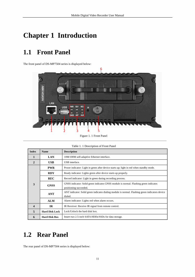
The front panel of DS-MP7504 series is displayed below:
1 2 3 4 5
6
Figure 1. 1 Front Panel
Table 1. 1 Description of Front Panel
Index Name Description
1 LAN 10M/100M self-adaptive Ethernet interface.
2 USB USB interface.
3
PWR Power indicator: Light in green after device starts up; light in red when standby mode.
RDY Ready indicator: Lights green after device starts up properly.
REC Record indicator: Light in green during recording process.
GNSS GNSS indicator: Solid green indicates GNSS module is normal. Flashing green indicates
positioning succeeded.
ANT ANT indicator: Solid green indicates dialing module is normal. Flashing green indicators device
dialed.
ALM Alarm indicator: Lights red when alarm occurs.
4 IR IR Receiver: Receive IR signal from remote control.
5 Hard Disk Lock Lock/Unlock the hard disk box.
6 Hard Disk Box Insert two 2.5-inch SATA HDDs/SSDs for data storage.
1.2 Rear Panel
The rear panel of DS-MP7504 series is displayed below:
Mobile Digital Video Recorder User Manual
12
1 2 3 4 5
6 7 8 9 10 11
12
13
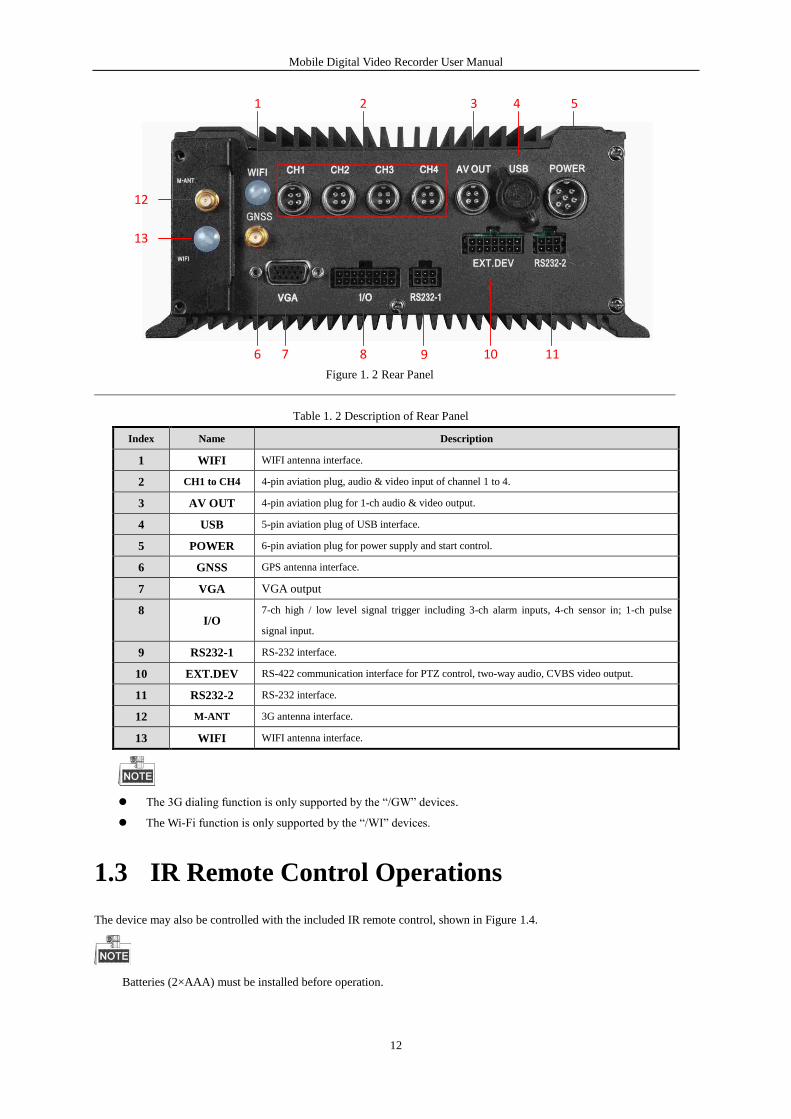
Figure 1. 2 Rear Panel
Table 1. 2 Description of Rear Panel
Index Name Description
1 WIFI WIFI antenna interface.
2 CH1 to CH4 4-pin aviation plug, audio & video input of channel 1 to 4.
3 AV OUT 4-pin aviation plug for 1-ch audio & video output.
4 USB 5-pin aviation plug of USB interface.
5 POWER 6-pin aviation plug for power supply and start control.
6 GNSS GPS antenna interface.
7 VGA VGA output
8 I/O
7-ch high / low level signal trigger including 3-ch alarm inputs, 4-ch sensor in; 1-ch pulse
signal input.
9 RS232-1 RS-232 interface.
10 EXT.DEV RS-422 communication interface for PTZ control, two-way audio, CVBS video output.
11 RS232-2 RS-232 interface.
12 M-ANT 3G antenna interface.
13 WIFI WIFI antenna interface.
The 3G dialing function is only supported by the “/GW” devices.
The Wi-Fi function is only supported by the “/WI” devices.
1.3 IR Remote Control Operations
The device may also be controlled with the included IR remote control, shown in Figure 1.4.
Batteries (2×AAA) must be installed before operation.
Mobile Digital Video Recorder User Manual
13
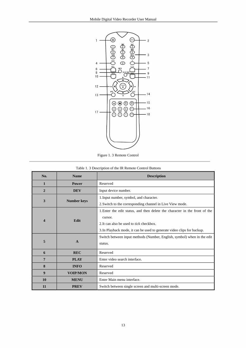
Figure 1. 3 Remote Control
Table 1. 3 Description of the IR Remote Control Buttons
No. Name Description
1 Power Reserved
2 DEV Input device number.
3 Number keys 1. Input number, symbol, and character.
2. Switch to the corresponding channel in Live View mode.
4 Edit
1. Enter the edit status, and then delete the character in the front of the
cursor.
2. It can also be used to tick checkbox.
3. In Playback mode, it can be used to generate video clips for backup.
5 A
Switch between input methods (Number, English, symbol) when in the edit
status.
6 REC Reserved
7 PLAY Enter video search interface.
8 INFO Reserved
9 VOIP/MON Reserved
10 MENU Enter Main menu interface.
11 PREV Switch between single screen and multi-screen mode.
Mobile Digital Video Recorder User Manual
14
12
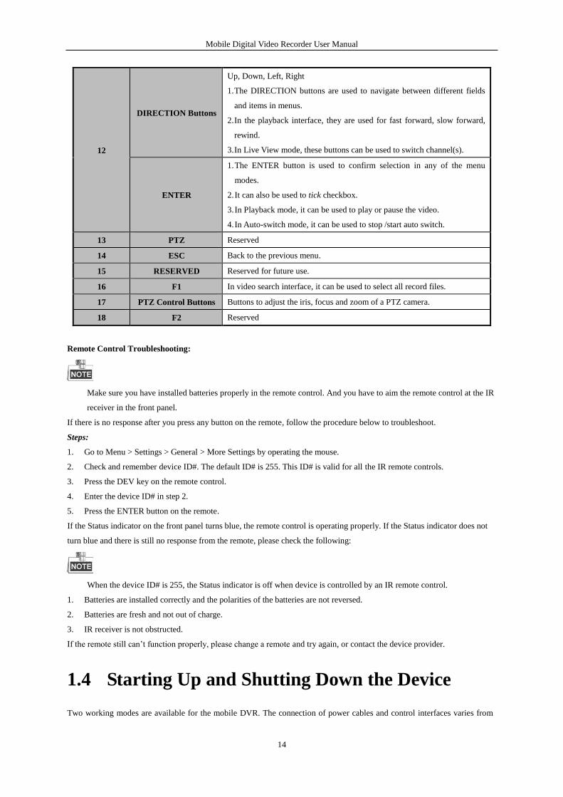
DIRECTION Buttons
Up, Down, Left, Right
1. The DIRECTION buttons are used to navigate between different fields
and items in menus.
2. In the playback interface, they are used for fast forward, slow forward,
rewind.
3. In Live View mode, these buttons can be used to switch channel(s).
ENTER
1. The ENTER button is used to confirm selection in any of the menu
modes.
2. It can also be used to tick checkbox.
3. In Playback mode, it can be used to play or pause the video.
4. In Auto-switch mode, it can be used to stop /start auto switch.
13 PTZ Reserved
14 ESC Back to the previous menu.
15 RESERVED Reserved for future use.
16 F1 In video search interface, it can be used to select all record files.
17 PTZ Control Buttons Buttons to adjust the iris, focus and zoom of a PTZ camera.
18 F2 Reserved
Remote Control Troubleshooting:
Make sure you have installed batteries properly in the remote control. And you have to aim the remote control at the IR
receiver in the front panel.
If there is no response after you press any button on the remote, follow the procedure below to troubleshoot.
Steps:
1. Go to Menu > Settings > General > More Settings by operating the mouse.
2. Check and remember device ID#. The default ID# is 255. This ID# is valid for all the IR remote controls.
3. Press the DEV key on the remote control.
4. Enter the device ID# in step 2.
5. Press the ENTER button on the remote.
If the Status indicator on the front panel turns blue, the remote control is operating properly. If the Status indicator does not
turn blue and there is still no response from the remote, please check the following:
When the device ID# is 255, the Status indicator is off when device is controlled by an IR remote control.
1. Batteries are installed correctly and the polarities of the batteries are not reversed.
2. Batteries are fresh and not out of charge.
3. IR receiver is not obstructed.
If the remote still can’t function properly, please change a remote and try again, or contact the device provider.
1.4 Starting Up and Shutting Down the Device
Two working modes are available for the mobile DVR. The connection of power cables and control interfaces varies from
Mobile Digital Video Recorder User Manual
15
the device working mode.
Vehicle ignition startup and time-delay shutdown
The mobile DVR starts up when the vehicle ignites and shuts down according to the pre-defined delay time after the vehicle
is off. The startup and shutdown of the device depend on the vehicle ignition signal.
Timing on/off
The mobile DVR starts up or shuts down automatically according to the pre-defined time and the device works separately
from the running status of the vehicle.
1.4.1 Vehicle Ignition Startup and Time-delay Shutdown
The vehicle ignition startup and time-delay shutdown are realized by the vehicle ignition switch, which includes positive
pole ignition switch (providing high level signal when the switch closes) and negative pole ignition switch (providing low
level signal when the switch closes). The wire connection of the device varies from different vehicle ignition switch.
For detailed time settings of time-delay shutdown, see Chapter 6.1
Please contact the vehicle manufacturer for the connection information of starting switch.
The vehicle ignition switch, also called car key, controls the startup and shutdown of the vehicle. Most of the cars
adopts positive pole ignition switch currently.
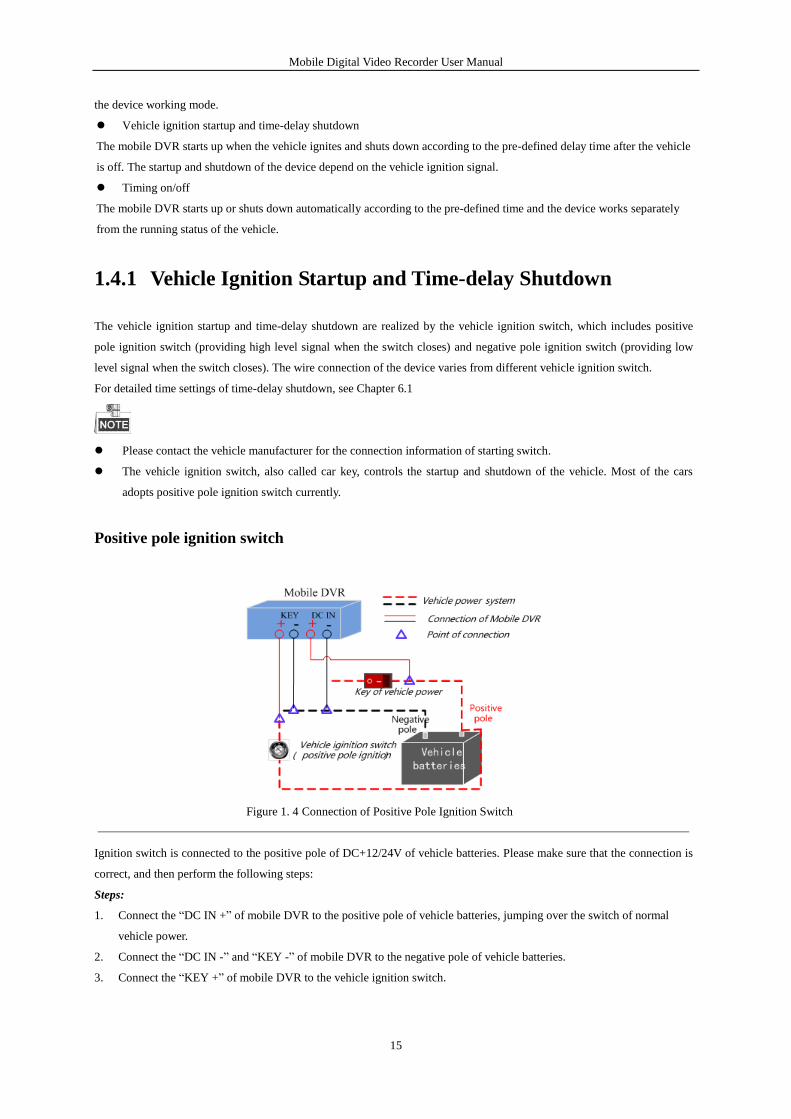
Positive pole ignition switch
Figure 1. 4 Connection of Positive Pole Ignition Switch
Ignition switch is connected to the positive pole of DC+12/24V of vehicle batteries. Please make sure that the connection is
correct, and then perform the following steps:
Steps:
1. Connect the “DC IN +” of mobile DVR to the positive pole of vehicle batteries, jumping over the switch of normal
vehicle power.
2. Connect the “DC IN -” and “KEY -” of mobile DVR to the negative pole of vehicle batteries.
3. Connect the “KEY +” of mobile DVR to the vehicle ignition switch.
Mobile Digital Video Recorder User Manual
16
The normal vehicle power refers to the main power of the vehicle power supply system. After the vehicle is off, the
normal vehicle power still provides direct-current source for the other devices inside and generally a main switch is
used to turn on/off it.
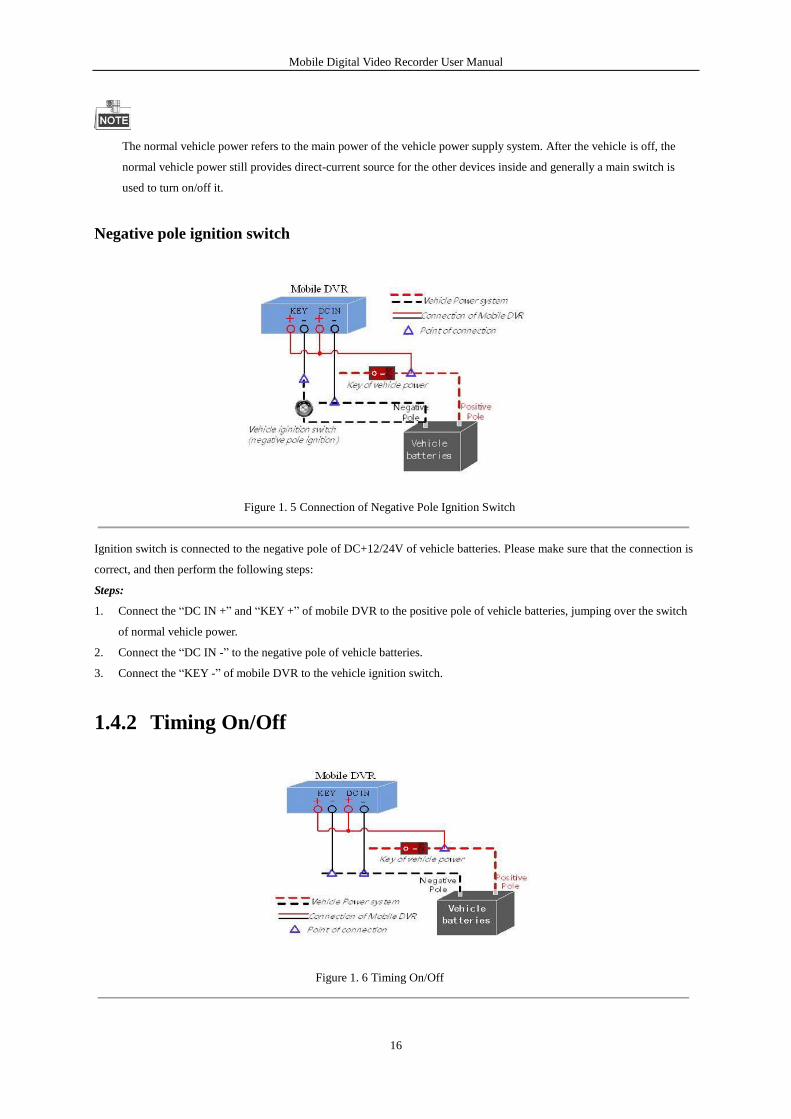
Negative pole ignition switch
Figure 1. 5 Connection of Negative Pole Ignition Switch
Ignition switch is connected to the negative pole of DC+12/24V of vehicle batteries. Please make sure that the connection is
correct, and then perform the following steps:
Steps:
1. Connect the “DC IN +” and “KEY +” of mobile DVR to the positive pole of vehicle batteries, jumping over the switch
of normal vehicle power.
2. Connect the “DC IN -” to the negative pole of vehicle batteries.
3. Connect the “KEY -” of mobile DVR to the vehicle ignition switch.
1.4.2 Timing On/Off
Figure 1. 6 Timing On/Off
Mobile Digital Video Recorder User Manual
17
Steps:
1. Connect the “DC IN +” and “KEY +” of mobile DVR to the positive pole of vehicle batteries.
2. Connect the “DC IN -” and “KEY -” of mobile DVR to the negative pole of vehicle batteries.
For detailed time settings of time-delay shutdown, see Chapter 6.1
1.5 Alarm Input / Output Connection
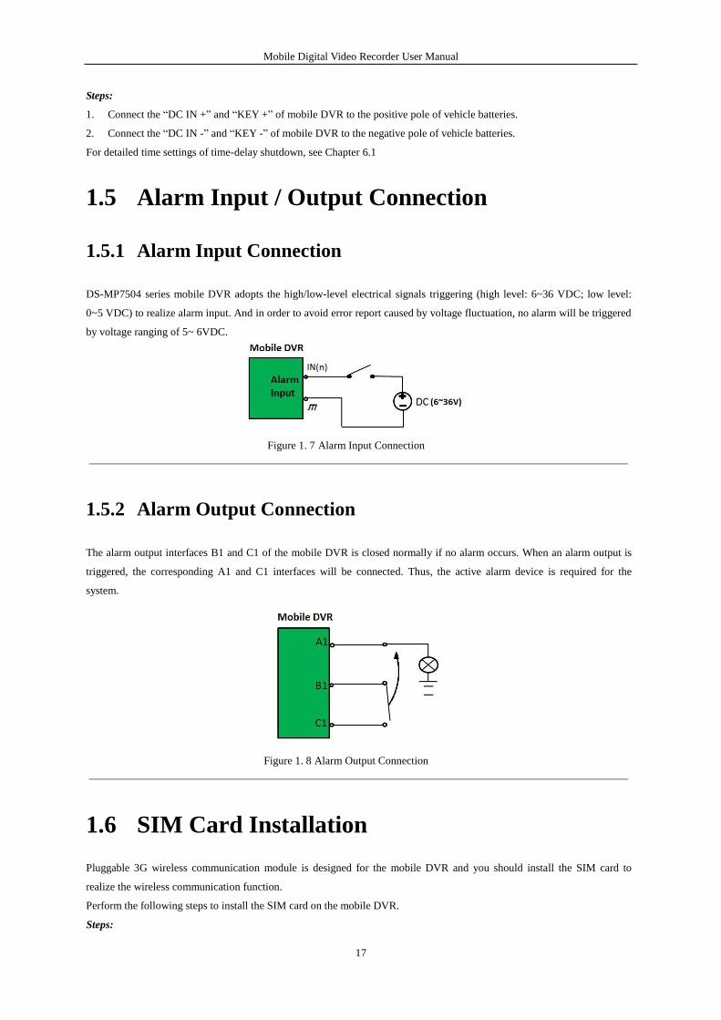
1.5.1 Alarm Input Connection
DS-MP7504 series mobile DVR adopts the high/low-level electrical signals triggering (high level: 6~36 VDC; low level:
0~5 VDC) to realize alarm input. And in order to avoid error report caused by voltage fluctuation, no alarm will be triggered
by voltage ranging of 5~ 6VDC.
Figure 1. 7 Alarm Input Connection
1.5.2 Alarm Output Connection
The alarm output interfaces B1 and C1 of the mobile DVR is closed normally if no alarm occurs. When an alarm output is
triggered, the corresponding A1 and C1 interfaces will be connected. Thus, the active alarm device is required for the
system.
Figure 1. 8 Alarm Output Connection
1.6 SIM Card Installation
Pluggable 3G wireless communication module is designed for the mobile DVR and you should install the SIM card to
realize the wireless communication function.
Perform the following steps to install the SIM card on the mobile DVR.
Steps:
Mobile Digital Video Recorder User Manual
18
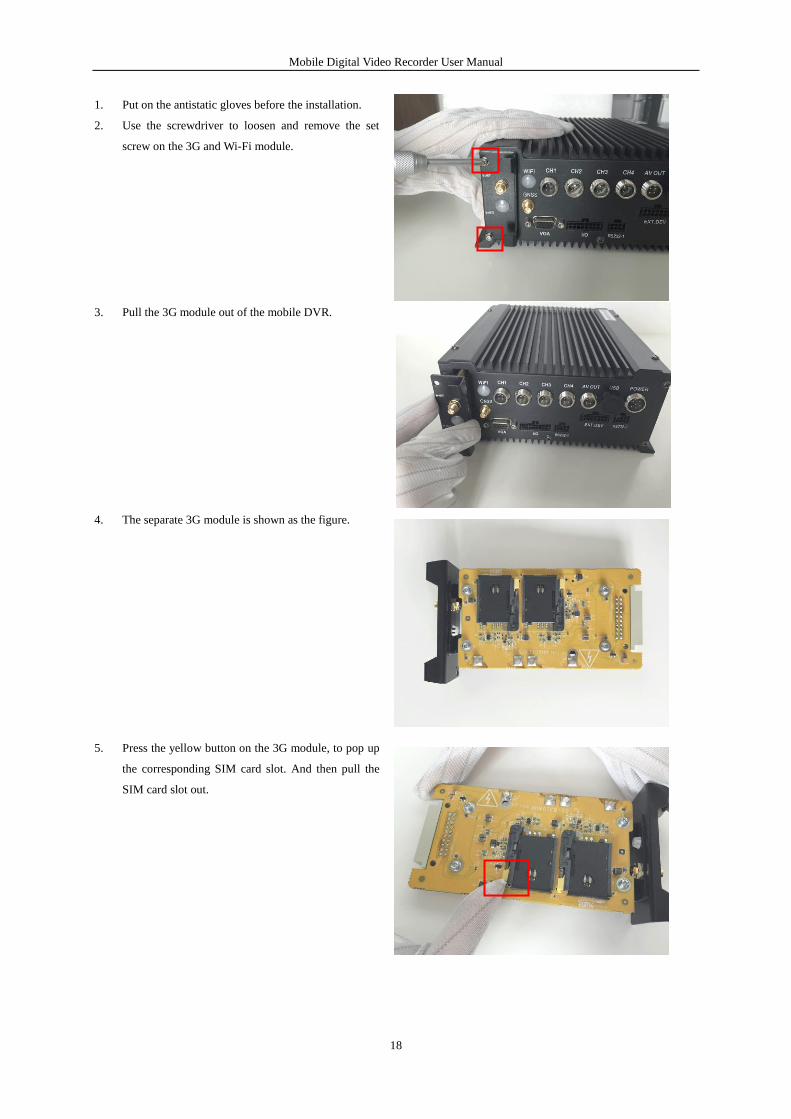
1. Put on the antistatic gloves before the installation.
2. Use the screwdriver to loosen and remove the set
screw on the 3G and Wi-Fi module.
3. Pull the 3G module out of the mobile DVR.
4. The separate 3G module is shown as the figure.
5. Press the yellow button on the 3G module, to pop up
the corresponding SIM card slot. And then pull the
SIM card slot out.
Mobile Digital Video Recorder User Manual
19
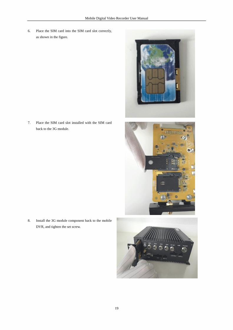
6. Place the SIM card into the SIM card slot correctly,
as shown in the figure.
7. Place the SIM card slot installed with the SIM card
back to the 3G module.
8. Install the 3G module component back to the mobile
DVR, and tighten the set screw.
Mobile Digital Video Recorder User Manual
20
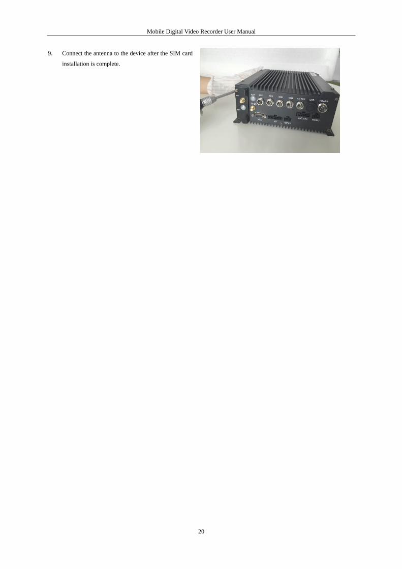
9. Connect the antenna to the device after the SIM card
installation is complete.
Mobile Digital Video Recorder User Manual
21
Chapter 2 Basic Operations
2.1 Setting Admin Password
Purpose:
For the first-time access, you need to activate the device by setting an admin password. No operation is allowed before
activation.
Steps:
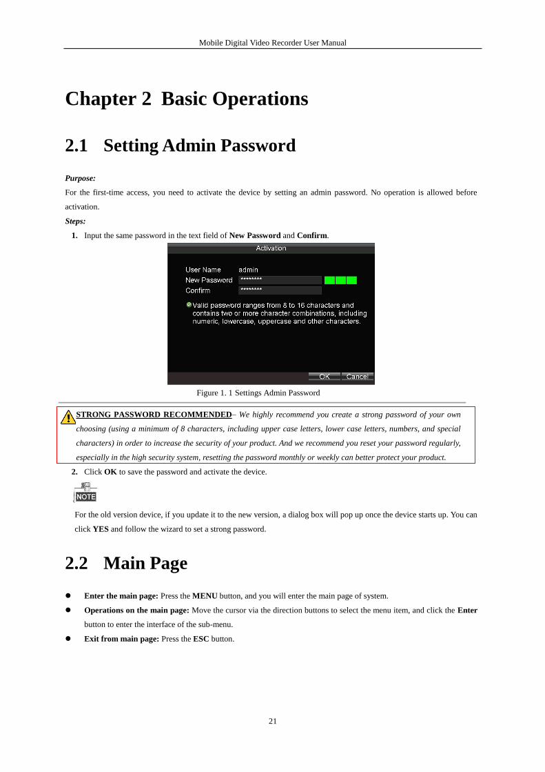
1. Input the same password in the text field of New Password and Confirm.
Figure 1. 1 Settings Admin Password
STRONG PASSWORD RECOMMENDED– We highly recommend you create a strong password of your own
choosing (using a minimum of 8 characters, including upper case letters, lower case letters, numbers, and special
characters) in order to increase the security of your product. And we recommend you reset your password regularly,
especially in the high security system, resetting the password monthly or weekly can better protect your product.
2. Click OK to save the password and activate the device.
For the old version device, if you update it to the new version, a dialog box will pop up once the device starts up. You can
click YES and follow the wizard to set a strong password.
2.2 Main Page
Enter the main page: Press the MENU button, and you will enter the main page of system.
Operations on the main page: Move the cursor via the direction buttons to select the menu item, and click the Enter
button to enter the interface of the sub-menu.
Exit from main page: Press the ESC button.
Mobile Digital Video Recorder User Manual
22
Figure 2. 1 Main Page
2.3 User Management
The admin user has all the operation permissions of the device.
Steps:
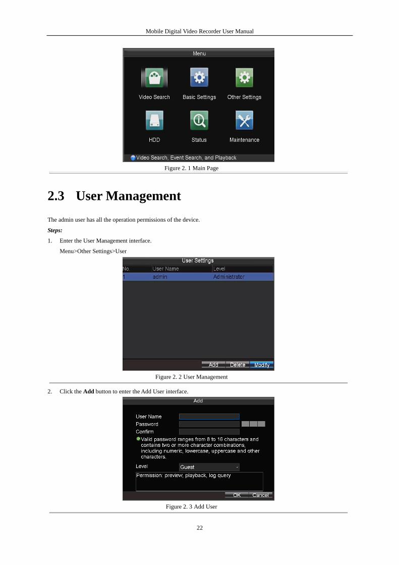
1. Enter the User Management interface.
Menu>Other Settings>User
Figure 2. 2 User Management
2. Click the Add button to enter the Add User interface.
Figure 2. 3 Add User
Mobile Digital Video Recorder User Manual
23
3. Input the information of the new user, including user name, password and confirm password.
STRONG PASSWORD RECOMMENDED– We highly recommend you create a strong password of your own
choosing (using a minimum of 8 characters, including upper case letters, lower case letters, numbers, and special
characters) in order to increase the security of your product. And we recommend you reset your password regularly,
especially in the high security system, resetting the password monthly or weekly can better protect your product.
4. Select the user level from the drop-down list.
Operator: The operator has permissions of Preview, Playback, Backup, Log Search and Parameters Settings.
Guest: The Guest has permission of Preview, Playback, Backup and Log Search.
5. Click the OK button to save the settings and go back to the User Management interface.
6. You can click the Delete button to delete the selected user and click the Modify button to modify the user information.
2.4 Display Settings
Purpose:
You can set the system time, select the CVBS output standard, enable the password, configure the DST settings, etc.
Steps:
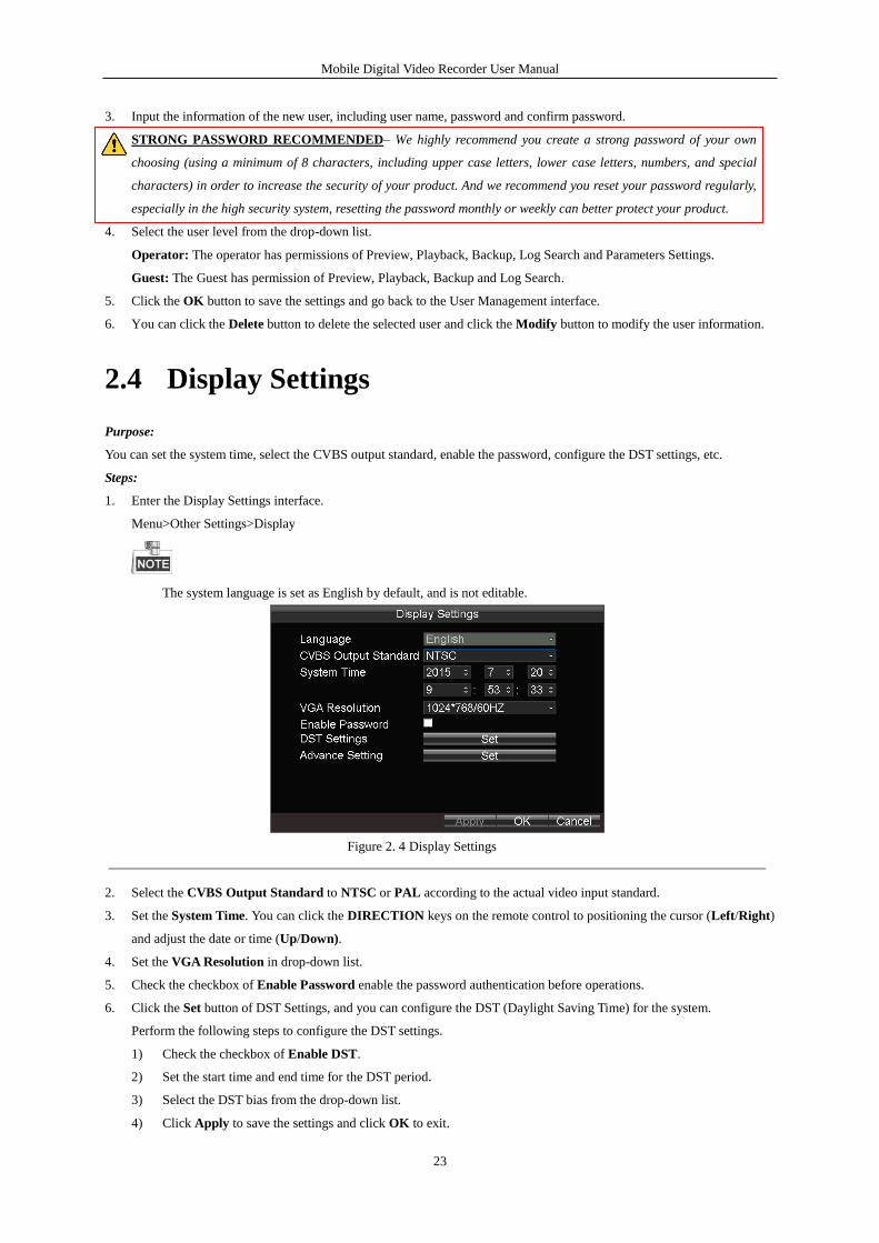
1. Enter the Display Settings interface.
Menu>Other Settings>Display
The system language is set as English by default, and is not editable.
Figure 2. 4 Display Settings
2. Select the CVBS Output Standard to NTSC or PAL according to the actual video input standard.
3. Set the System Time. You can click the DIRECTION keys on the remote control to positioning the cursor (Left/Right)
and adjust the date or time (Up/Down).
4. Set the VGA Resolution in drop-down list.
5. Check the checkbox of Enable Password enable the password authentication before operations.
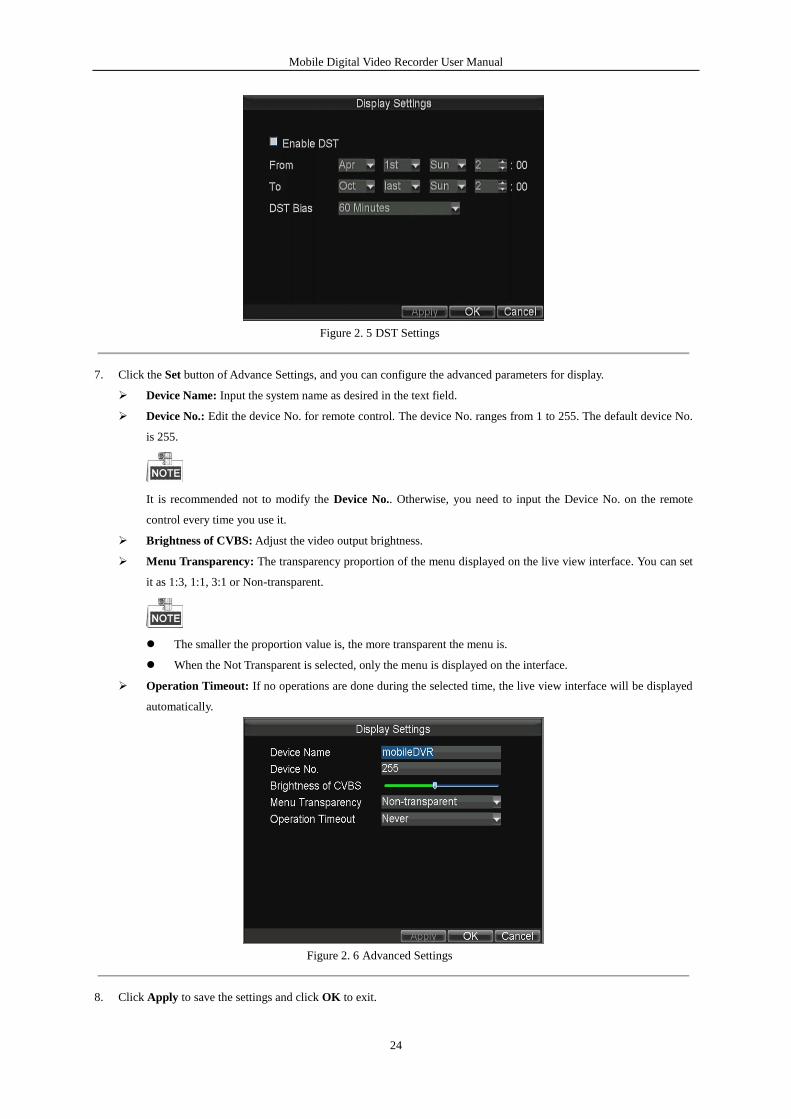
6. Click the Set button of DST Settings, and you can configure the DST (Daylight Saving Time) for the system.
Perform the following steps to configure the DST settings.
1) Check the checkbox of Enable DST.
2) Set the start time and end time for the DST period.
3) Select the DST bias from the drop-down list.
4) Click Apply to save the settings and click OK to exit.
Mobile Digital Video Recorder User Manual
24
Figure 2. 5 DST Settings
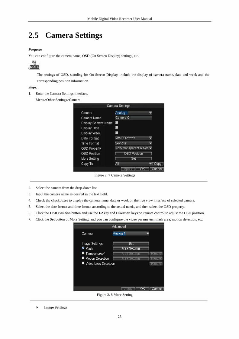
7. Click the Set button of Advance Settings, and you can configure the advanced parameters for display.
Device Name: Input the system name as desired in the text field.
Device No.: Edit the device No. for remote control. The device No. ranges from 1 to 255. The default device No.
is 255.
It is recommended not to modify the Device No.. Otherwise, you need to input the Device No. on the remote
control every time you use it.
Brightness of CVBS: Adjust the video output brightness.
Menu Transparency: The transparency proportion of the menu displayed on the live view interface. You can set
it as 1:3, 1:1, 3:1 or Non-transparent.
The smaller the proportion value is, the more transparent the menu is.
When the Not Transparent is selected, only the menu is displayed on the interface.
Operation Timeout: If no operations are done during the selected time, the live view interface will be displayed
automatically.
Figure 2. 6 Advanced Settings
8. Click Apply to save the settings and click OK to exit.
Mobile Digital Video Recorder User Manual
25
2.5 Camera Settings
Purpose:
You can configure the camera name, OSD (On Screen Display) settings, etc.
The settings of OSD, standing for On Screen Display, include the display of camera name, date and week and the
corresponding position information.
Steps:
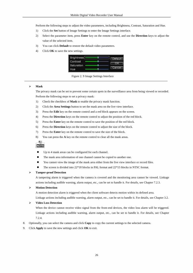
1. Enter the Camera Settings interface.
Menu>Other Settings>Camera
Figure 2. 7 Camera Settings
2. Select the camera from the drop-down list.
3. Input the camera name as desired in the text field.
4. Check the checkboxes to display the camera name, date or week on the live view interface of selected camera.
5. Select the date format and time format according to the actual needs, and then select the OSD property.
6. Click the OSD Position button and use the F2 key and Direction keys on remote control to adjust the OSD position.
7. Click the Set button of More Setting, and you can configure the video parameters, mask area, motion detection, etc.
Figure 2. 8 More Setting
Image Settings
Mobile Digital Video Recorder User Manual
26
Perform the following steps to adjust the video parameters, including Brightness, Contrast, Saturation and Hue.
1) Click the Set button of Image Settings to enter the Image Settings interface.
2) Select the parameter item, press Enter key on the remote control, and use the Direction keys to adjust the
value of the selected item.
3) You can click Default to restore the default video parameters.
4) Click OK to save the new settings.
Figure 2. 9 Image Settings Interface
Mask
The privacy mask can be set to prevent some certain spots in the surveillance area from being viewed or recorded.
Perform the following steps to set a privacy mask:
1) Check the checkbox of Mask to enable the privacy mask function.
2) Click the Area Settings button to set the mask area on the live view interface.
3) Press the Edit key on the remote control and a red block appears on the screen.
4) Press the Direction keys on the remote control to adjust the position of the red block.
5) Press the Enter key on the remote control to save the position of the red block.
6) Press the Direction keys on the remote control to adjust the size of the block.
7) Press the Enter key on the remote control to save the size of the block.
8) You can press the A key on the remote control to clear all the mask areas.
Up to 4 mask areas can be configured for each channel.
The mask area information of one channel cannot be copied to another one.
You cannot view the image of the mask area either from the live view interface or record files.
The screen is divided into 22*18 blocks in PAL format and 22*15 blocks in NTSC format.
Tamper-proof Detection
A tampering alarm is triggered when the camera is covered and the monitoring area cannot be viewed. Linkage
actions including audible warning, alarm output, etc., can be set to handle it. For details, see Chapter 7.2.3.
Motion Detection
A motion detection alarm is triggered when the client software detects motion within its defined area.
Linkage actions including audible warning, alarm output, etc., can be set to handle it. For details, see Chapter 3.2.
Video Loss Detection
When the device cannot receive video signal from the front-end devices, the video loss alarm will be triggered.
Linkage actions including audible warning, alarm output, etc., can be set to handle it. For details, see Chapter
7.2.4.
8. Optionally, you can select the camera and click Copy to copy the current settings to the selected camera.
9. Click Apply to save the new settings and click OK to exit.
Mobile Digital Video Recorder User Manual
27
2.6 Preview Settings
Purpose:
You can configure the dwell time of live view window, set the camera order, enable/disable the audio preview, etc.
Steps:
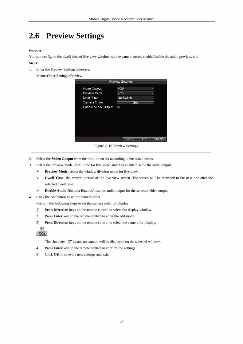
1. Enter the Preview Settings interface.
Menu>Other Settings>Preview
Figure 2. 10 Preview Settings
2. Select the Video Output from the drop-down list according to the actual needs.
3. Select the preview mode, dwell time for live view, and then enable/disable the audio output.
Preview Mode: select the window division mode for live view.
Dwell Time: the switch interval of the live view screen. The screen will be switched to the next one after the
selected dwell time.
Enable Audio Output: Enables/disables audio output for the selected video output.
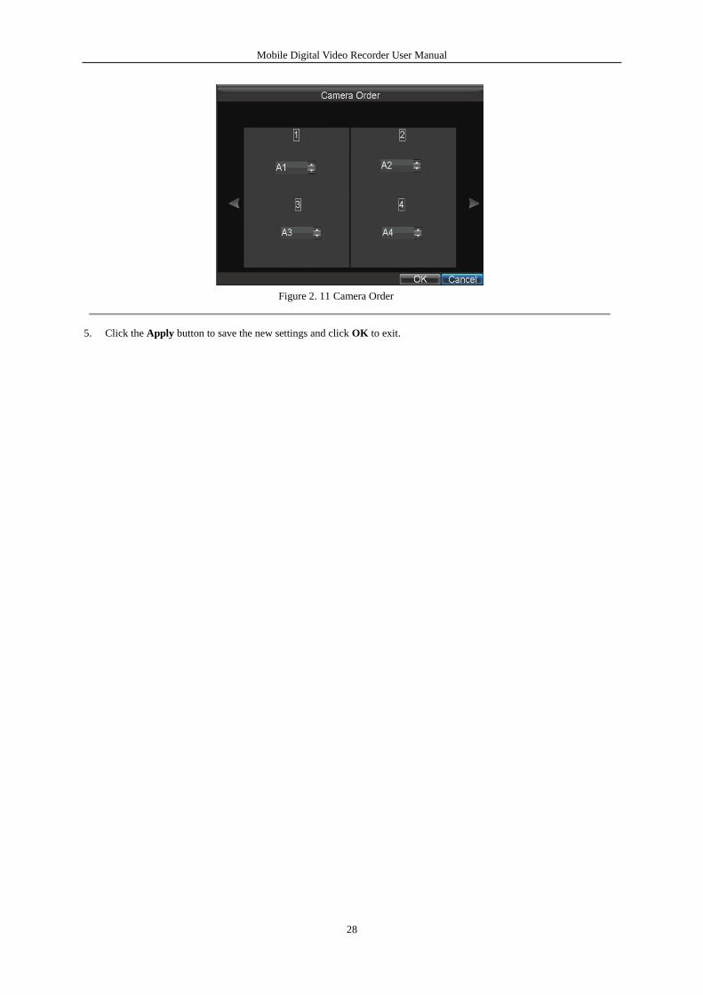
4. Click the Set button to set the camera order.
Perform the following steps to set the camera order for display:
1) Press Direction keys on the remote control to select the display window.
2) Press Enter key on the remote control to enter the edit mode.
3) Press Direction keys on the remote control to select the camera for display.
The character “X” means no camera will be displayed on the selected window.
4) Press Enter key on the remote control to confirm the settings.
5) Click OK to save the new settings and exit.
Mobile Digital Video Recorder User Manual
28
Figure 2. 11 Camera Order
5. Click the Apply button to save the new settings and click OK to exit.
Mobile Digital Video Recorder User Manual
29
Chapter 3 Record Settings
3.1 Configuring Encoding Parameters
3.1.1 Initializing the HDD
Before you start:
Install at least one HDD card on the mobile DVR for video data storage.
Steps:
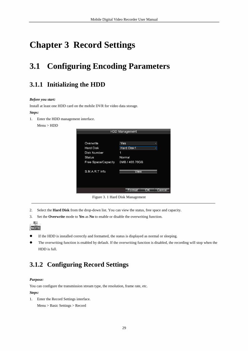
1. Enter the HDD management interface.
Menu > HDD
Figure 3. 1 Hard Disk Management
2. Select the Hard Disk from the drop-down list. You can view the status, free space and capacity.
3. Set the Overwrite mode to Yes as No to enable or disable the overwriting function.
If the HDD is installed correctly and formatted, the status is displayed as normal or sleeping.
The overwriting function is enabled by default. If the overwriting function is disabled, the recording will stop when the
HDD is full.
3.1.2 Configuring Record Settings
Purpose:
You can configure the transmission stream type, the resolution, frame rate, etc.
Steps:
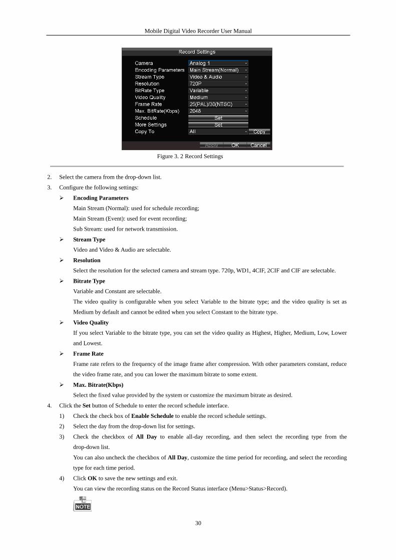
1. Enter the Record Settings interface.
Menu > Basic Settings > Record
Mobile Digital Video Recorder User Manual
30
Figure 3. 2 Record Settings
2. Select the camera from the drop-down list.
3. Configure the following settings:
Encoding Parameters
Main Stream (Normal): used for schedule recording;
Main Stream (Event): used for event recording;
Sub Stream: used for network transmission.
Stream Type
Video and Video & Audio are selectable.
Resolution
Select the resolution for the selected camera and stream type. 720p, WD1, 4CIF, 2CIF and CIF are selectable.
Bitrate Type
Variable and Constant are selectable.
The video quality is configurable when you select Variable to the bitrate type; and the video quality is set as
Medium by default and cannot be edited when you select Constant to the bitrate type.
Video Quality
If you select Variable to the bitrate type, you can set the video quality as Highest, Higher, Medium, Low, Lower
and Lowest.
Frame Rate
Frame rate refers to the frequency of the image frame after compression. With other parameters constant, reduce
the video frame rate, and you can lower the maximum bitrate to some extent.
Max. Bitrate(Kbps)
Select the fixed value provided by the system or customize the maximum bitrate as desired.
4. Click the Set button of Schedule to enter the record schedule interface.
1) Check the check box of Enable Schedule to enable the record schedule settings.
2) Select the day from the drop-down list for settings.
3) Check the checkbox of All Day to enable all-day recording, and then select the recording type from the
drop-down list.
You can also uncheck the checkbox of All Day, customize the time period for recording, and select the recording
type for each time period.
4) Click OK to save the new settings and exit.
You can view the recording status on the Record Status interface (Menu>Status>Record).
Mobile Digital Video Recorder User Manual
31
5 recording types are selectable: Normal, Motion Detection, Alarm, Motion | Alarm and Motion & Alarm.
Up to 8 time periods can be set for each day and each of the time periods cannot be overlapped.
Figure 3. 3 Record Schedule Settings
5. Click the Set button of More Settings to configure the pre-record and post-record time.
Pre-record: Normally used for the event (motion or alarm) triggered record, when you want to record before the
event happens. For example, when an alarm occurs at 10:00, if the pre-record time is set as 5 seconds, the camera
records the alarm at 9:59:55.
Post-record: After the event finished, the video can also be recorded for a certain time. For example, when an
alarm ends at 11:00, if the post-record time is set as 5 seconds, the camera records till 11:00:05.
6. Optionally, you can select the camera and click Copy to copy the current settings to the selected camera.
7. Click Apply to save the settings and click OK to exit.
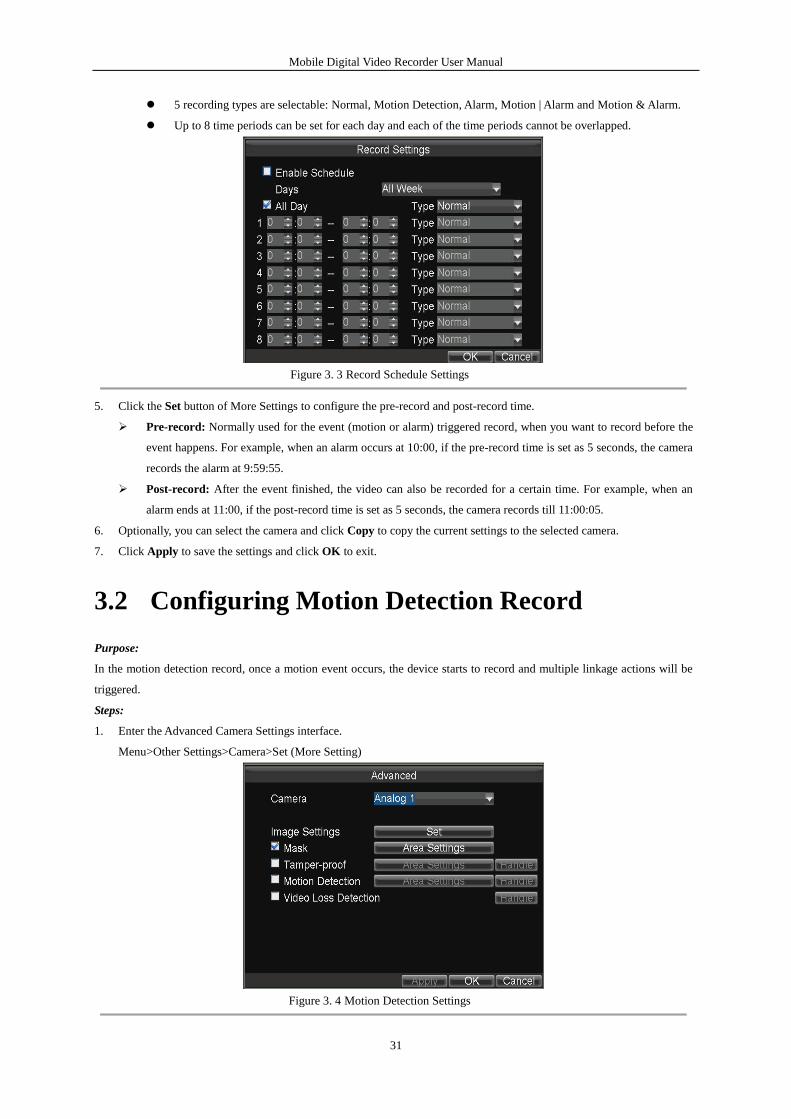
3.2 Configuring Motion Detection Record
Purpose:
In the motion detection record, once a motion event occurs, the device starts to record and multiple linkage actions will be
triggered.
Steps:
1. Enter the Advanced Camera Settings interface.
Menu>Other Settings>Camera>Set (More Setting)
Figure 3. 4 Motion Detection Settings
Mobile Digital Video Recorder User Manual
32
2. Check the checkbox of Motion Detection to enable the motion detection function.
3. Click the Area Settings button to set the area for motion detection.
Perform the following steps to set a specified area for motion detection:
1) Press the Edit key on the remote control and a red block appears on the screen.
2) Press the Direction keys on the remote control to adjust the position of the red block.
3) Press the Enter key on the remote control to save the position of the red block.
4) Press the Direction keys on the remote control to adjust the size of the block.
5) Press the Enter key on the remote control to save the size of the block.
6) Press the Menu key on the remote control to set the detection sensitivity. You can set the level as 1~6 or off. Click
OK to save the settings.
7) You can press the A key on the remote control to clear all the mask areas.
8) Press the Enter key on the remote control to save the settings and then press Esc key to exit.
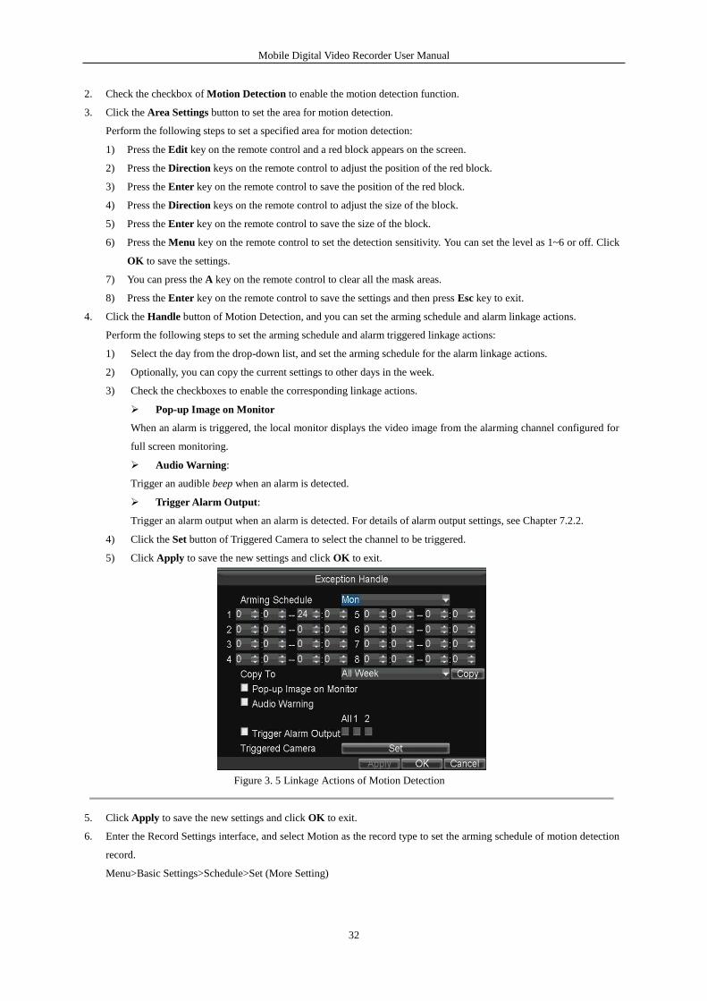
4. Click the Handle button of Motion Detection, and you can set the arming schedule and alarm linkage actions.
Perform the following steps to set the arming schedule and alarm triggered linkage actions:
1) Select the day from the drop-down list, and set the arming schedule for the alarm linkage actions.
2) Optionally, you can copy the current settings to other days in the week.
3) Check the checkboxes to enable the corresponding linkage actions.
Pop-up Image on Monitor
When an alarm is triggered, the local monitor displays the video image from the alarming channel configured for
full screen monitoring.
Audio Warning:
Trigger an audible beep when an alarm is detected.
Trigger Alarm Output:
Trigger an alarm output when an alarm is detected. For details of alarm output settings, see Chapter 7.2.2.
4) Click the Set button of Triggered Camera to select the channel to be triggered.
5) Click Apply to save the new settings and click OK to exit.
Figure 3. 5 Linkage Actions of Motion Detection
5. Click Apply to save the new settings and click OK to exit.
6. Enter the Record Settings interface, and select Motion as the record type to set the arming schedule of motion detection
record.
Menu>Basic Settings>Schedule>Set (More Setting)
Mobile Digital Video Recorder User Manual
33
3.3 Configuring Alarm Triggered Record
Purpose:
Follow the procedure to configure alarm triggered recording.
Steps:
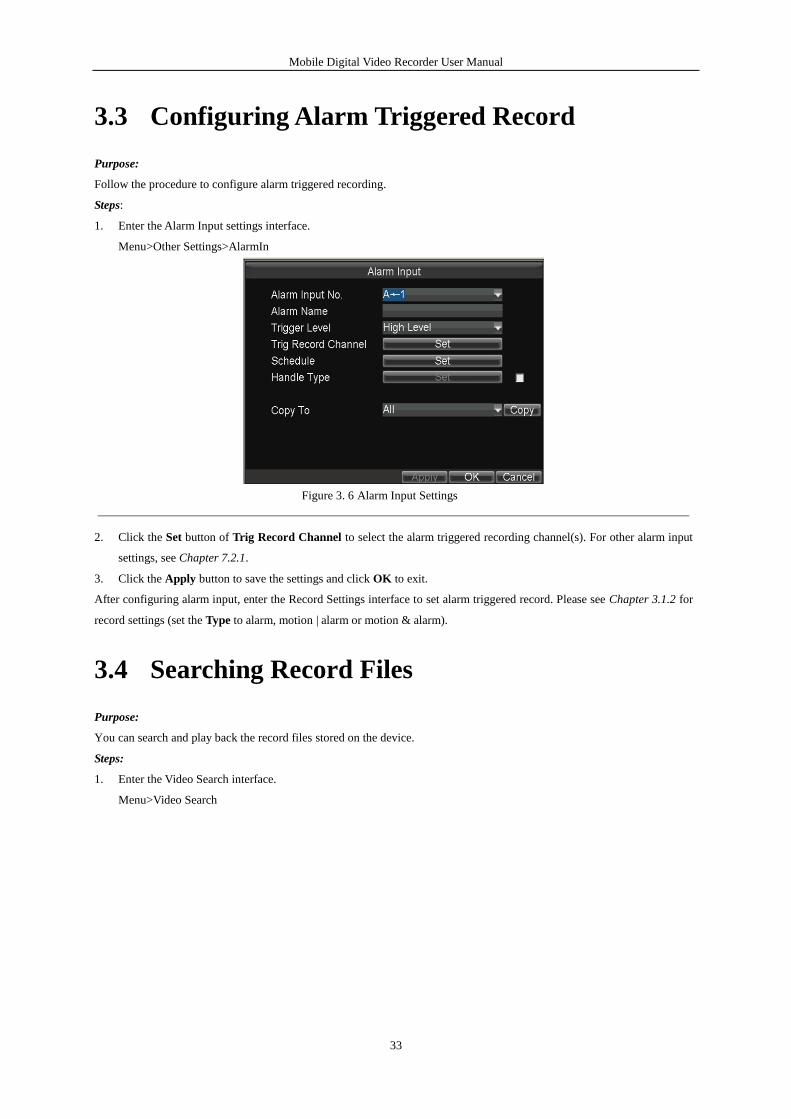
1. Enter the Alarm Input settings interface.
Menu>Other Settings>AlarmIn
Figure 3. 6 Alarm Input Settings
2. Click the Set button of Trig Record Channel to select the alarm triggered recording channel(s). For other alarm input
settings, see Chapter 7.2.1.
3. Click the Apply button to save the settings and click OK to exit.
After configuring alarm input, enter the Record Settings interface to set alarm triggered record. Please see Chapter 3.1.2 for
record settings (set the Type to alarm, motion | alarm or motion & alarm).
3.4 Searching Record Files
Purpose:
You can search and play back the record files stored on the device.
Steps:
1. Enter the Video Search interface.
Menu>Video Search
Mobile Digital Video Recorder User Manual
34
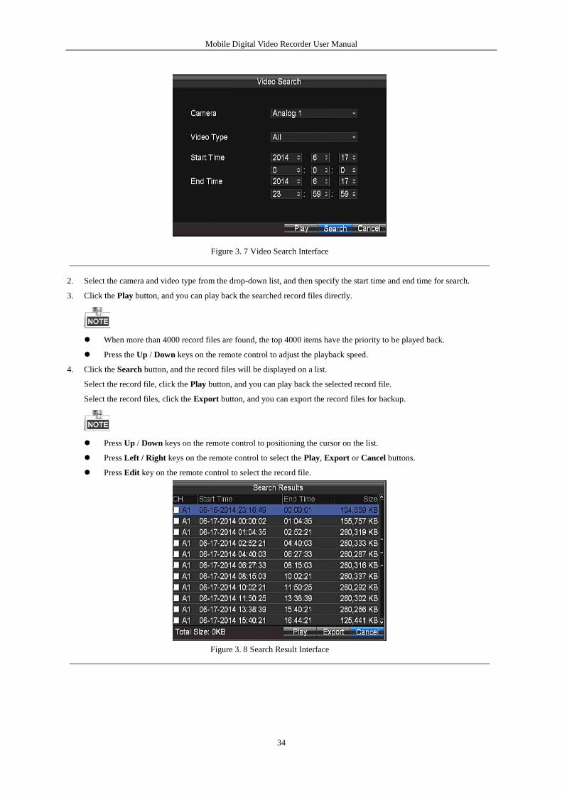
Figure 3. 7 Video Search Interface
2. Select the camera and video type from the drop-down list, and then specify the start time and end time for search.
3. Click the Play button, and you can play back the searched record files directly.
When more than 4000 record files are found, the top 4000 items have the priority to be played back.
Press the Up / Down keys on the remote control to adjust the playback speed.
4. Click the Search button, and the record files will be displayed on a list.
Select the record file, click the Play button, and you can play back the selected record file.
Select the record files, click the Export button, and you can export the record files for backup.
Press Up / Down keys on the remote control to positioning the cursor on the list.
Press Left / Right keys on the remote control to select the Play, Export or Cancel buttons.
Press Edit key on the remote control to select the record file.
Figure 3. 8 Search Result Interface
Mobile Digital Video Recorder User Manual
35
Chapter 4 PTZ Controls
4.1 Configuring PTZ Settings
Purpose:
Follow the procedure to set the parameters for PTZ. The configuring of the PTZ parameters should be done before you
control the PTZ camera.
Before you start:
Connect the RS-485 cables of PTZ camera to EXT.DEV interface of the mobile DVR.
Steps:
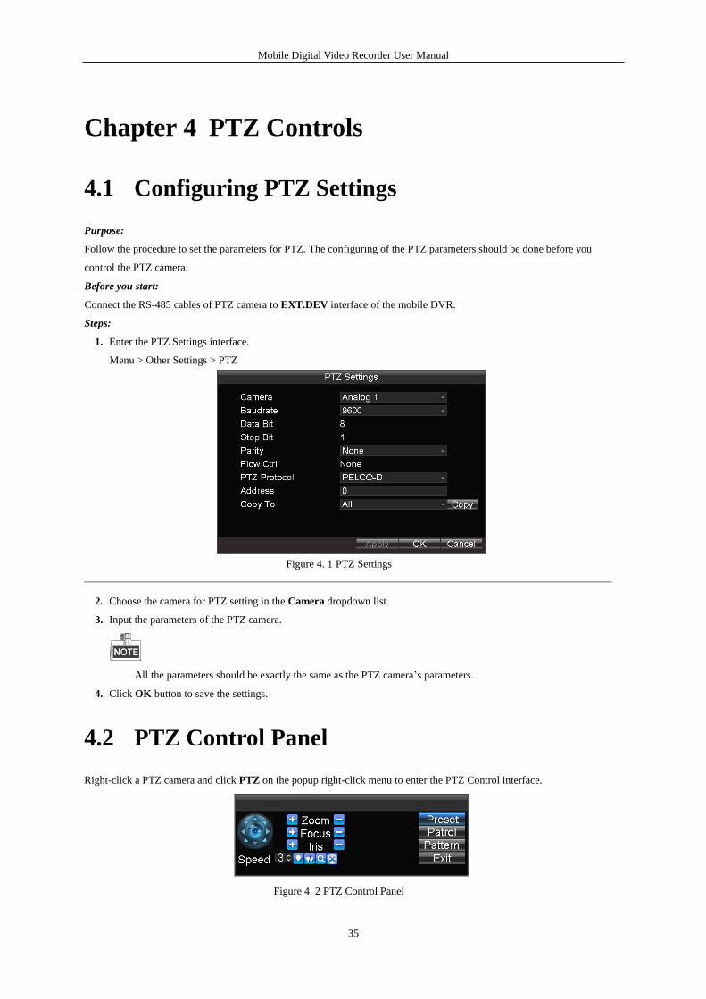
1. Enter the PTZ Settings interface.
Menu > Other Settings > PTZ
Figure 4. 1 PTZ Settings
2. Choose the camera for PTZ setting in the Camera dropdown list.
3. Input the parameters of the PTZ camera.
All the parameters should be exactly the same as the PTZ camera’s parameters.
4. Click OK button to save the settings.
4.2 PTZ Control Panel
Right-click a PTZ camera and click PTZ on the popup right-click menu to enter the PTZ Control interface.
Figure 4. 2 PTZ Control Panel
Mobile Digital Video Recorder User Manual
36
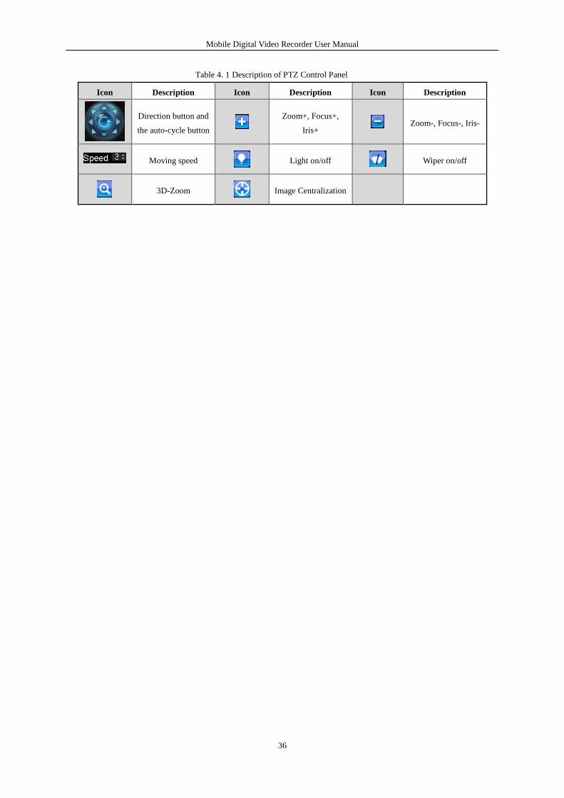
Table 4. 1 Description of PTZ Control Panel
Icon Description Icon Description Icon Description
Direction button and
the auto-cycle button
Zoom+, Focus+,
Iris+ Zoom-, Focus-, Iris-
Moving speed
Light on/off Wiper on/off
3D-Zoom
Image Centralization
Mobile Digital Video Recorder User Manual
37
Chapter 5 Wireless Network Settings
5.1 Dialing Settings
Before you start:
Install a 3G SIM card on the mobile DVR.
Dialing function is only supported by DS-MP7504/GW and DS- MP7504/GW/WI series.
Steps:
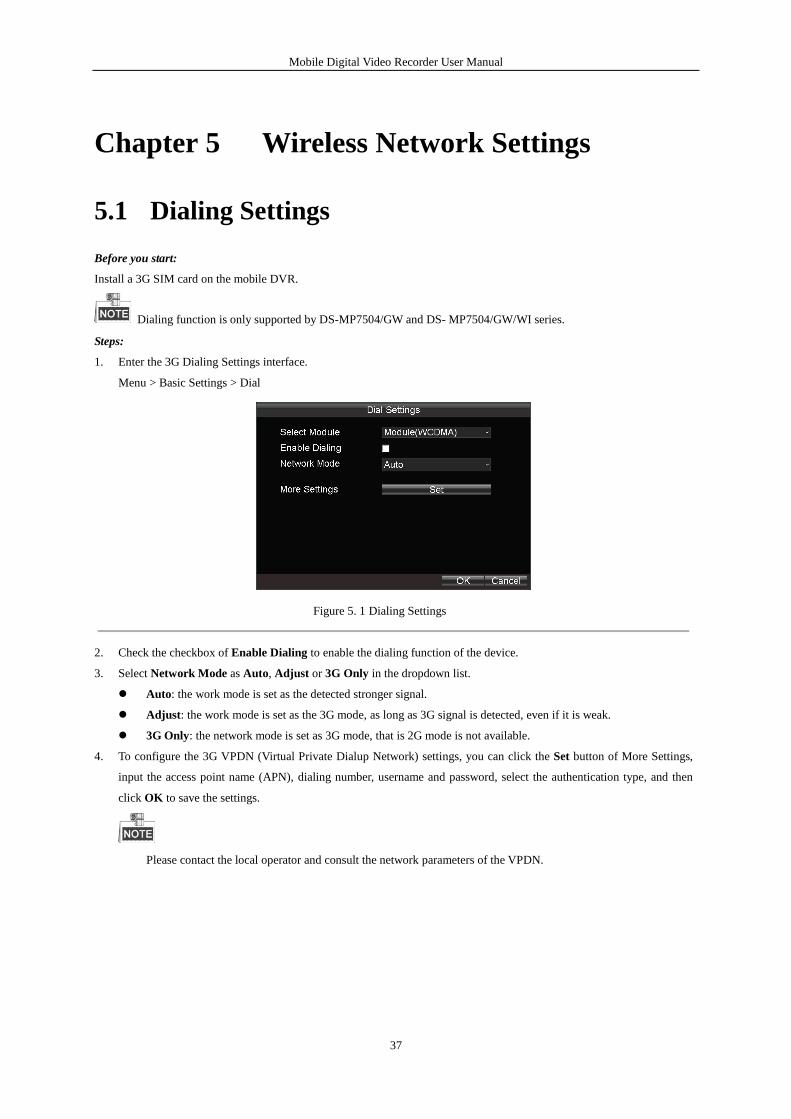
1. Enter the 3G Dialing Settings interface.
Menu > Basic Settings > Dial
Figure 5. 1 Dialing Settings
2. Check the checkbox of Enable Dialing to enable the dialing function of the device.
3. Select Network Mode as Auto, Adjust or 3G Only in the dropdown list.
Auto: the work mode is set as the detected stronger signal.
Adjust: the work mode is set as the 3G mode, as long as 3G signal is detected, even if it is weak.
3G Only: the network mode is set as 3G mode, that is 2G mode is not available.
4. To configure the 3G VPDN (Virtual Private Dialup Network) settings, you can click the Set button of More Settings,
input the access point name (APN), dialing number, username and password, select the authentication type, and then
click OK to save the settings.
Please contact the local operator and consult the network parameters of the VPDN.
Mobile Digital Video Recorder User Manual
38
Figure 5. 2 Private Network Settings
5. Click OK and reboot the device to activate the new settings.
You can view the dialing status on the Dialing Status interface (Menu>Status>Dial).
The PIN management function is reserved.
5.2 Wi-Fi Settings
Purpose:
You can connect the device to the Wi-Fi networks and transmit the data via the Wi-Fi.
Wi-Fi function is only supported by DS-MP7504/GW/WI series.
Steps:
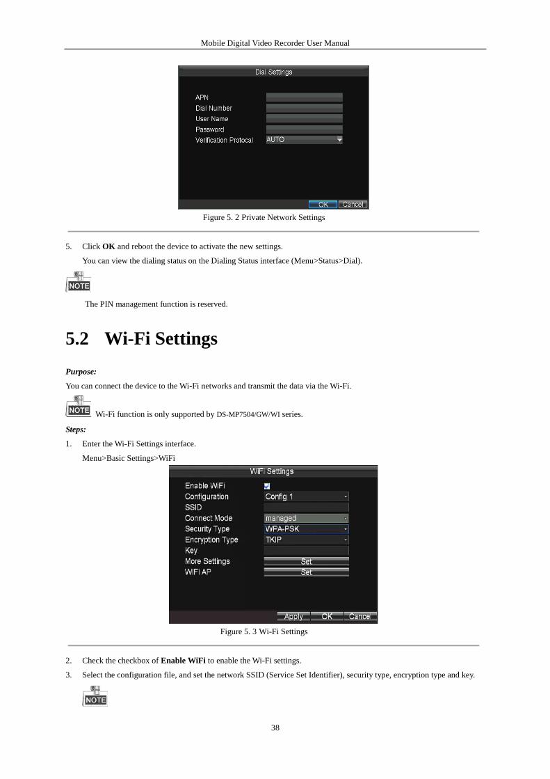
1. Enter the Wi-Fi Settings interface.
Menu>Basic Settings>WiFi
Figure 5. 3 Wi-Fi Settings
2. Check the checkbox of Enable WiFi to enable the Wi-Fi settings.
3. Select the configuration file, and set the network SSID (Service Set Identifier), security type, encryption type and key.
Mobile Digital Video Recorder User Manual
39
5 configuration files are available and only one SSID can be set for each file.
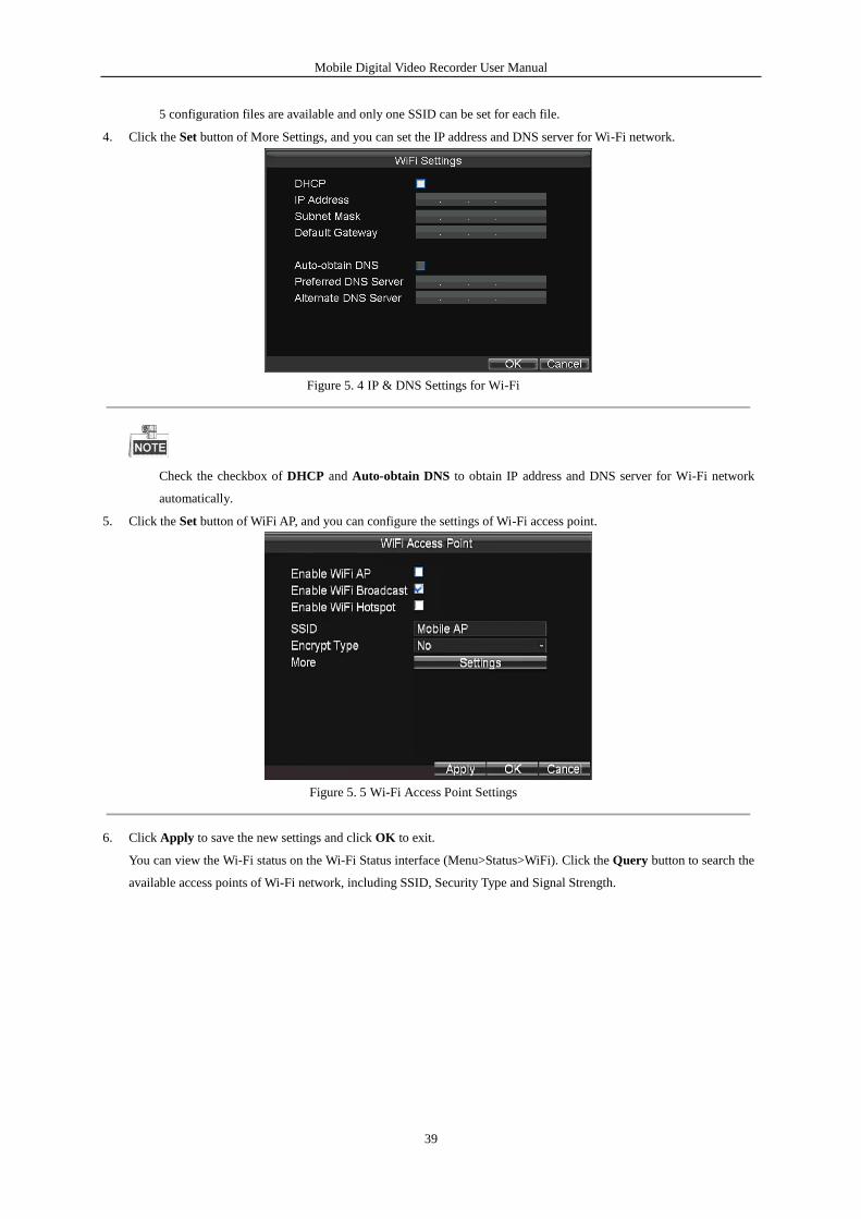
4. Click the Set button of More Settings, and you can set the IP address and DNS server for Wi-Fi network.
Figure 5. 4 IP & DNS Settings for Wi-Fi
Check the checkbox of DHCP and Auto-obtain DNS to obtain IP address and DNS server for Wi-Fi network
automatically.
5. Click the Set button of WiFi AP, and you can configure the settings of Wi-Fi access point.
Figure 5. 5 Wi-Fi Access Point Settings
6. Click Apply to save the new settings and click OK to exit.
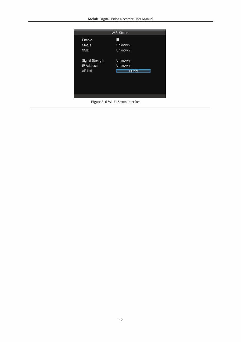
You can view the Wi-Fi status on the Wi-Fi Status interface (Menu>Status>WiFi). Click the Query button to search the
available access points of Wi-Fi network, including SSID, Security Type and Signal Strength.
Mobile Digital Video Recorder User Manual
40
Figure 5. 6 Wi-Fi Status Interface
Mobile Digital Video Recorder User Manual
41
Chapter 6 Platform Settings
The Mobile DVR can be remotely accessed via 2 platforms: iVMS platform and Push Mode platform. Make sure the
parameters configured are valid for the platform you select for login.
6.1 Accessing by iVMS Platform
Before you start:
Create the device ID of mobile DVR on the iVMS platform.
Steps:
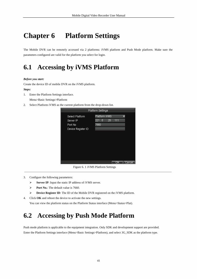
1. Enter the Platform Settings interface.
Menu>Basic Settings>Platform
2. Select Platform iVMS as the current platform from the drop-down list.
Figure 6. 1 iVMS Platform Settings
3. Configure the following parameters:
Server IP: Input the static IP address of iVMS server.
Port No.: The default value is 7660.
Device Register ID: The ID of the Mobile DVR registered on the iVMS platform.
4. Click OK and reboot the device to activate the new settings.
You can view the platform status on the Platform Status interface (Menu>Status>Plat).
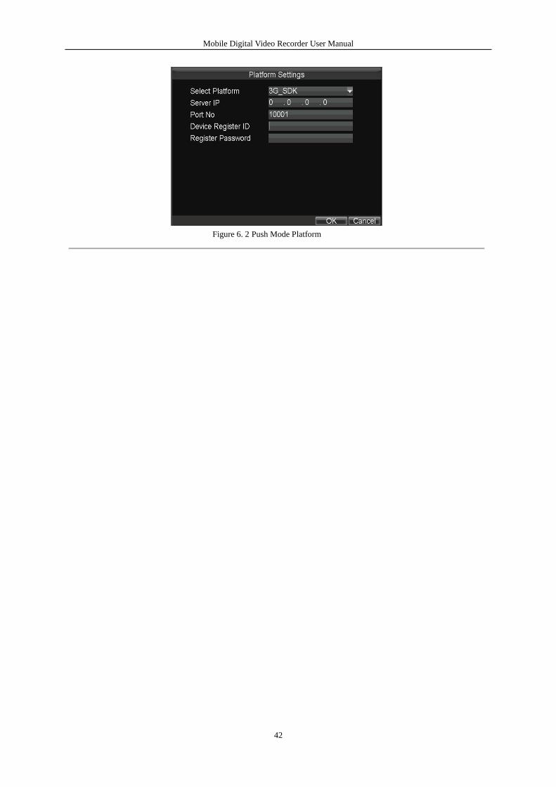
6.2 Accessing by Push Mode Platform
Push mode platform is applicable to the equipment integration. Only SDK and development support are provided.
Enter the Platform Settings interface (Menu>Basic Settings>Platform), and select 3G_SDK as the platform type.
Mobile Digital Video Recorder User Manual
42
Figure 6. 2 Push Mode Platform
Mobile Digital Video Recorder User Manual
43
Chapter 7 Mobile Specified Functions
7.1 Configuring Startup and Shutdown
Purpose:
You can set the shutdown delay time (Vehicle Ignition Startup and Shutdown) or specify the startup/shutdown time (Timing
On/Off) for the mobile DVR.
For Vehicle Ignition Startup and Shutdown
Steps:
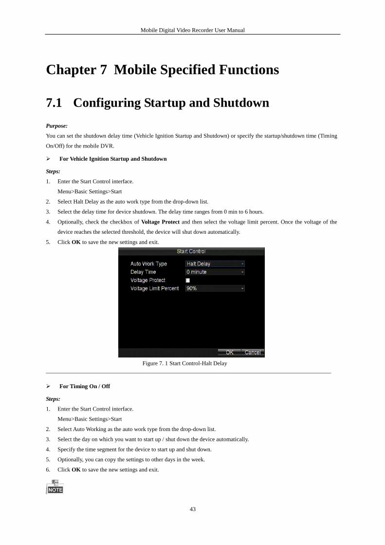
1. Enter the Start Control interface.
Menu>Basic Settings>Start
2. Select Halt Delay as the auto work type from the drop-down list.
3. Select the delay time for device shutdown. The delay time ranges from 0 min to 6 hours.
4. Optionally, check the checkbox of Voltage Protect and then select the voltage limit percent. Once the voltage of the
device reaches the selected threshold, the device will shut down automatically.
5. Click OK to save the new settings and exit.
Figure 7. 1 Start Control-Halt Delay
For Timing On / Off
Steps:
1. Enter the Start Control interface.
Menu>Basic Settings>Start
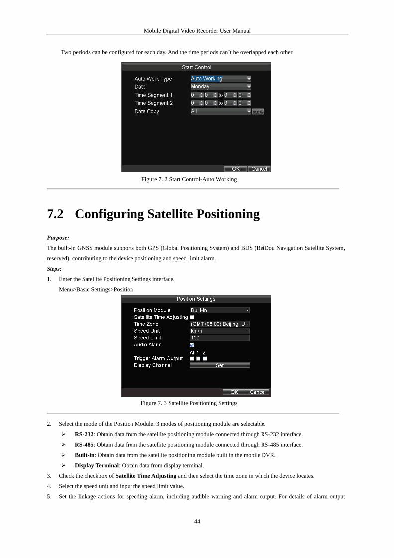
2. Select Auto Working as the auto work type from the drop-down list.
3. Select the day on which you want to start up / shut down the device automatically.
4. Specify the time segment for the device to start up and shut down.
5. Optionally, you can copy the settings to other days in the week.
6. Click OK to save the new settings and exit.
Mobile Digital Video Recorder User Manual
44
Two periods can be configured for each day. And the time periods can’t be overlapped each other.
Figure 7. 2 Start Control-Auto Working
7.2 Configuring Satellite Positioning
Purpose:
The built-in GNSS module supports both GPS (Global Positioning System) and BDS (BeiDou Navigation Satellite System,
reserved), contributing to the device positioning and speed limit alarm.
Steps:
1. Enter the Satellite Positioning Settings interface.
Menu>Basic Settings>Position
Figure 7. 3 Satellite Positioning Settings
2. Select the mode of the Position Module. 3 modes of positioning module are selectable.
RS-232: Obtain data from the satellite positioning module connected through RS-232 interface.
RS-485: Obtain data from the satellite positioning module connected through RS-485 interface.
Built-in: Obtain data from the satellite positioning module built in the mobile DVR.
Display Terminal: Obtain data from display terminal.
3. Check the checkbox of Satellite Time Adjusting and then select the time zone in which the device locates.
4. Select the speed unit and input the speed limit value.
5. Set the linkage actions for speeding alarm, including audible warning and alarm output. For details of alarm output
Mobile Digital Video Recorder User Manual
45
settings, see Chapter 7.2.2.
6. Click the Set button, check the checkboxes of display channels, and click OK to go back to upper menu. Then the
device positioning information will be displayed on the selected channels
The number of the display channels varies from the device models.
7. Click OK to save the new settings and exit.
You can view the device positioning status on the Positioning Status interface (Menu>Status>Position).
7.3 Configuring G-Sensor Alarm
Purpose:
G-Sensor detects and records the acceleration speed information in 3-axial (X, Y, Z) directions.
Before you start:
Connect an external sensor to the device for obtaining and providing the acceleration speed in 3-axial directions.
Steps:
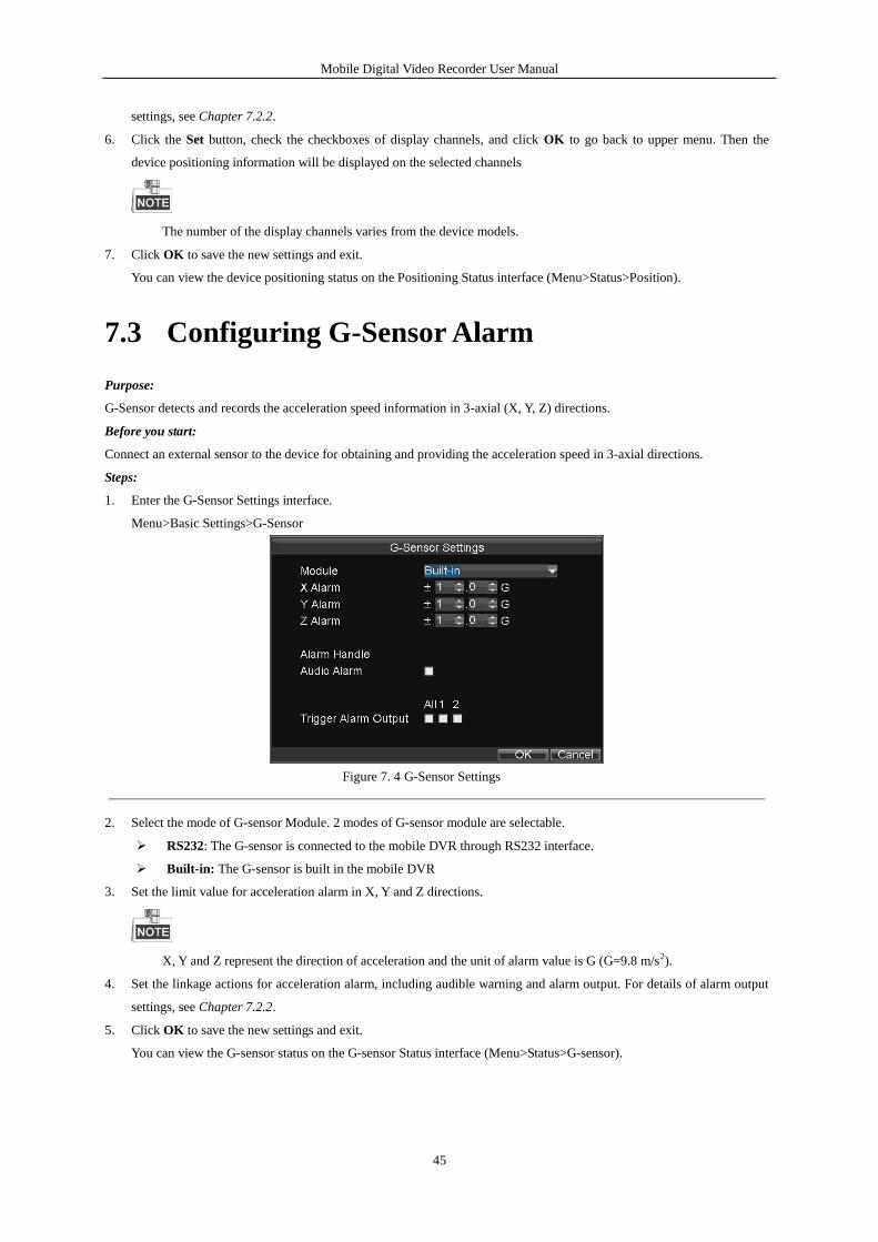
1. Enter the G-Sensor Settings interface.
Menu>Basic Settings>G-Sensor
Figure 7. 4 G-Sensor Settings
2. Select the mode of G-sensor Module. 2 modes of G-sensor module are selectable.
RS232: The G-sensor is connected to the mobile DVR through RS232 interface.
Built-in: The G-sensor is built in the mobile DVR
3. Set the limit value for acceleration alarm in X, Y and Z directions.
X, Y and Z represent the direction of acceleration and the unit of alarm value is G (G=9.8 m/s2).
4. Set the linkage actions for acceleration alarm, including audible warning and alarm output. For details of alarm output
settings, see Chapter 7.2.2.
5. Click OK to save the new settings and exit.
You can view the G-sensor status on the G-sensor Status interface (Menu>Status>G-sensor).
Mobile Digital Video Recorder User Manual
46
7.4 Configuring Sensor-In
Purpose:
Sensor-In detects and records the driving information of the vehicle, including pedal braking, turning left/right, reversing,
etc.
Steps:
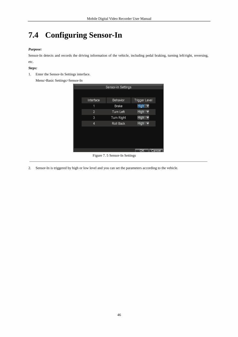
1. Enter the Sensor-In Settings interface.
Menu>Basic Settings>Sensor-In
Figure 7. 5 Sensor-In Settings
2. Sensor-In is triggered by high or low level and you can set the parameters according to the vehicle.
Mobile Digital Video Recorder User Manual
47
Chapter 8 Other Functions
8.1 Local Network Settings
Steps:
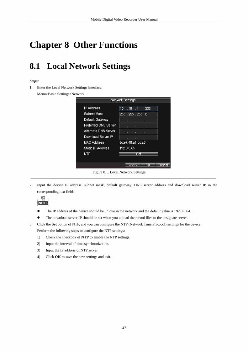
1. Enter the Local Network Settings interface.
Menu>Basic Settings>Network
Figure 8. 1 Local Network Settings
2. Input the device IP address, subnet mask, default gateway, DNS server address and download server IP in the
corresponding text fields.
The IP address of the device should be unique in the network and the default value is 192.0.0.64.
The download server IP should be set when you upload the record files to the designate server.
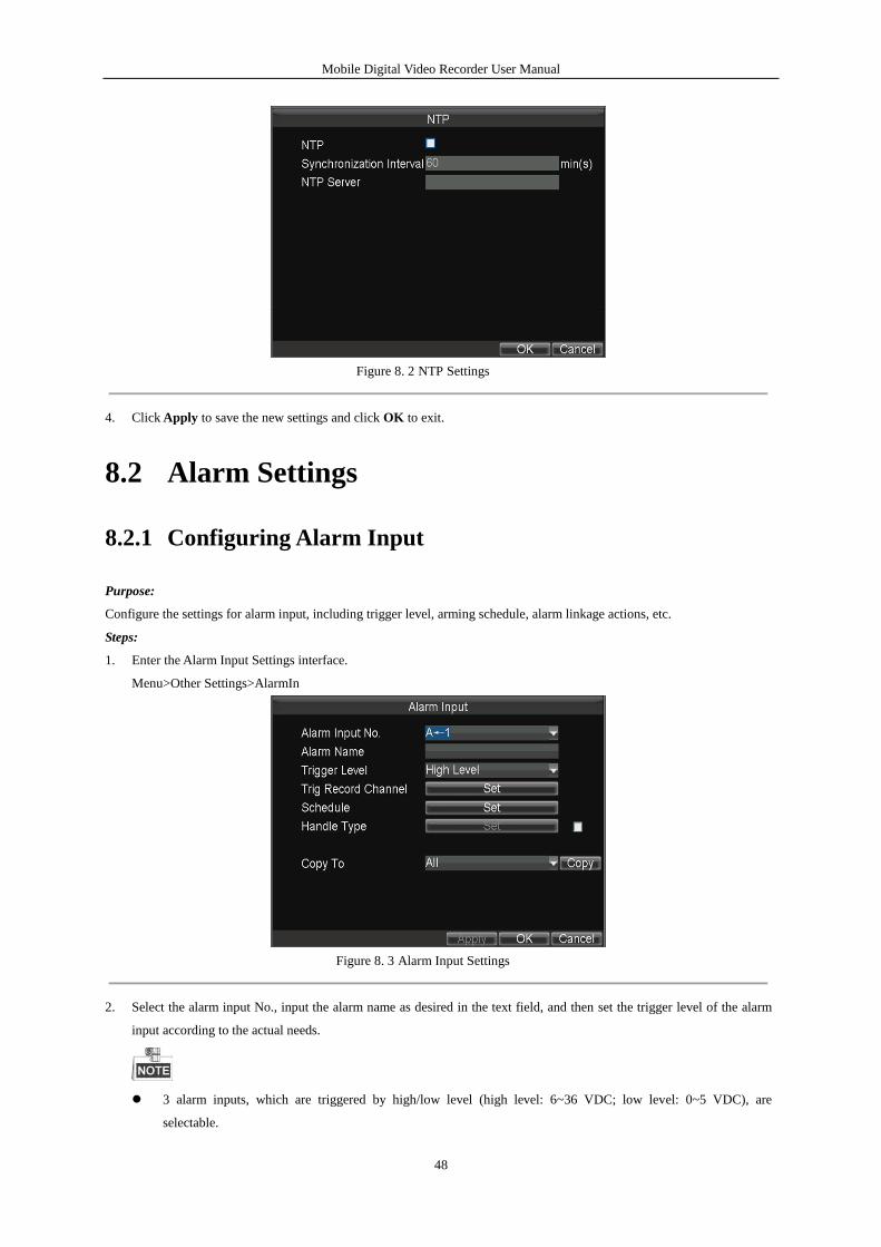
3. Click the Set button of NTP, and you can configure the NTP (Network Time Protocol) settings for the device.
Perform the following steps to configure the NTP settings:
1) Check the checkbox of NTP to enable the NTP settings.
2) Input the interval of time synchronization.
3) Input the IP address of NTP server.
4) Click OK to save the new settings and exit.
Mobile Digital Video Recorder User Manual
48
Figure 8. 2 NTP Settings
4. Click Apply to save the new settings and click OK to exit.
8.2 Alarm Settings
8.2.1 Configuring Alarm Input
Purpose:
Configure the settings for alarm input, including trigger level, arming schedule, alarm linkage actions, etc.
Steps:
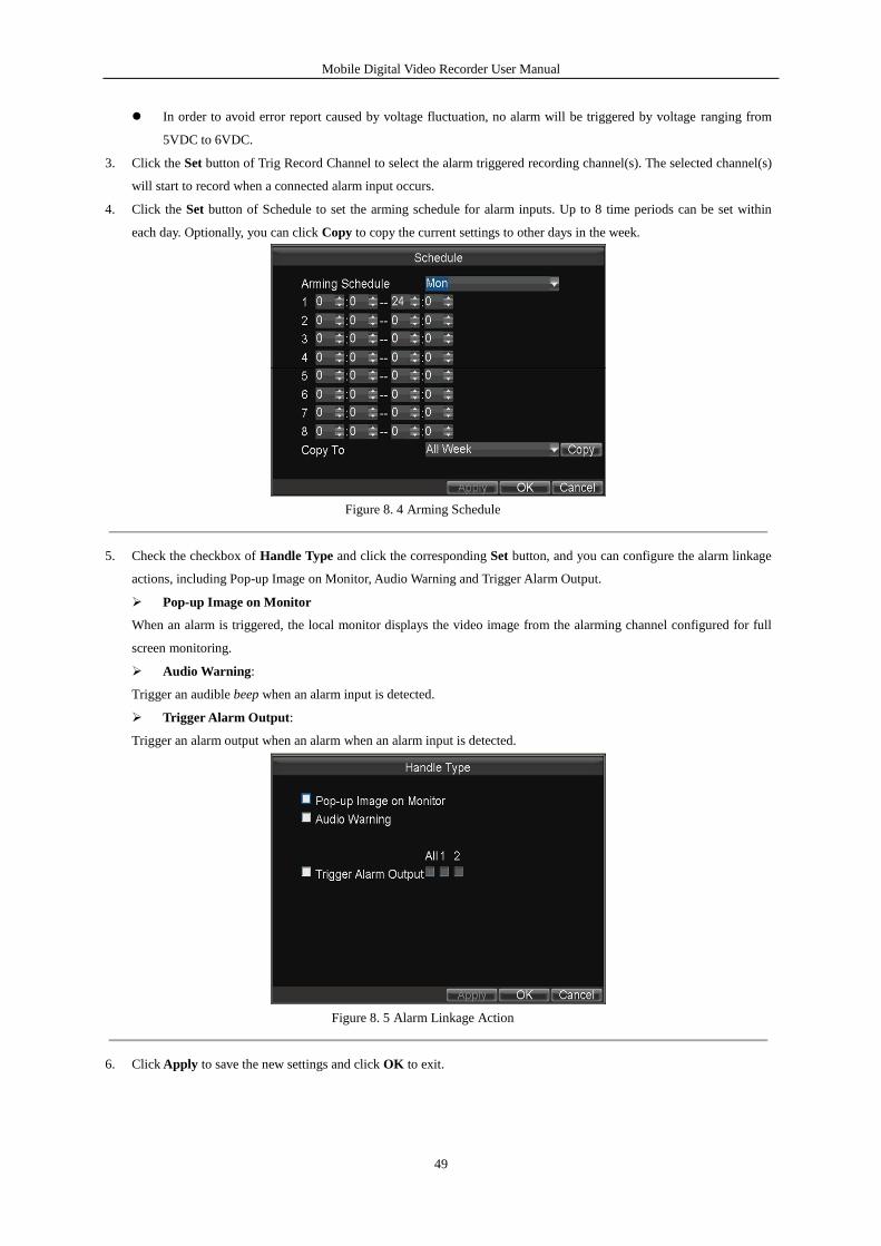
1. Enter the Alarm Input Settings interface.
Menu>Other Settings>AlarmIn
Figure 8. 3 Alarm Input Settings
2. Select the alarm input No., input the alarm name as desired in the text field, and then set the trigger level of the alarm
input according to the actual needs.
3 alarm inputs, which are triggered by high/low level (high level: 6~36 VDC; low level: 0~5 VDC), are
selectable.
Mobile Digital Video Recorder User Manual
49
In order to avoid error report caused by voltage fluctuation, no alarm will be triggered by voltage ranging from
5VDC to 6VDC.
3. Click the Set button of Trig Record Channel to select the alarm triggered recording channel(s). The selected channel(s)
will start to record when a connected alarm input occurs.
4. Click the Set button of Schedule to set the arming schedule for alarm inputs. Up to 8 time periods can be set within
each day. Optionally, you can click Copy to copy the current settings to other days in the week.
Figure 8. 4 Arming Schedule
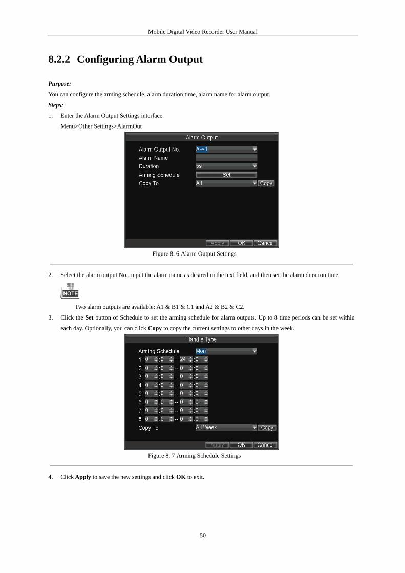
5. Check the checkbox of Handle Type and click the corresponding Set button, and you can configure the alarm linkage
actions, including Pop-up Image on Monitor, Audio Warning and Trigger Alarm Output.
Pop-up Image on Monitor
When an alarm is triggered, the local monitor displays the video image from the alarming channel configured for full
screen monitoring.
Audio Warning:
Trigger an audible beep when an alarm input is detected.
Trigger Alarm Output:
Trigger an alarm output when an alarm when an alarm input is detected.
Figure 8. 5 Alarm Linkage Action
6. Click Apply to save the new settings and click OK to exit.
Mobile Digital Video Recorder User Manual
50
8.2.2 Configuring Alarm Output
Purpose:
You can configure the arming schedule, alarm duration time, alarm name for alarm output.
Steps:
1. Enter the Alarm Output Settings interface.
Menu>Other Settings>AlarmOut
Figure 8. 6 Alarm Output Settings
2. Select the alarm output No., input the alarm name as desired in the text field, and then set the alarm duration time.
Two alarm outputs are available: A1 & B1 & C1 and A2 & B2 & C2.
3. Click the Set button of Schedule to set the arming schedule for alarm outputs. Up to 8 time periods can be set within
each day. Optionally, you can click Copy to copy the current settings to other days in the week.
Figure 8. 7 Arming Schedule Settings
4. Click Apply to save the new settings and click OK to exit.
Mobile Digital Video Recorder User Manual
51
8.2.3 Configuring Video Tampering Alarm
Purpose:
A tampering alarm is triggered when the camera is covered and the monitoring area cannot be viewed. Linkage actions
including audible warning, alarm output, etc., can be set to handle it.
Steps:
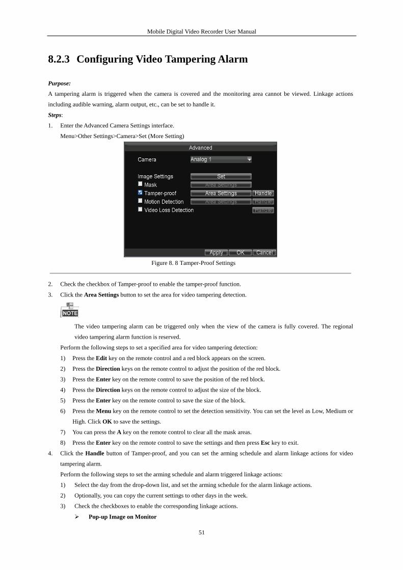
1. Enter the Advanced Camera Settings interface.
Menu>Other Settings>Camera>Set (More Setting)
Figure 8. 8 Tamper-Proof Settings
2. Check the checkbox of Tamper-proof to enable the tamper-proof function.
3. Click the Area Settings button to set the area for video tampering detection.
The video tampering alarm can be triggered only when the view of the camera is fully covered. The regional
video tampering alarm function is reserved.
Perform the following steps to set a specified area for video tampering detection:
1) Press the Edit key on the remote control and a red block appears on the screen.
2) Press the Direction keys on the remote control to adjust the position of the red block.
3) Press the Enter key on the remote control to save the position of the red block.
4) Press the Direction keys on the remote control to adjust the size of the block.
5) Press the Enter key on the remote control to save the size of the block.
6) Press the Menu key on the remote control to set the detection sensitivity. You can set the level as Low, Medium or
High. Click OK to save the settings.
7) You can press the A key on the remote control to clear all the mask areas.
8) Press the Enter key on the remote control to save the settings and then press Esc key to exit.
4. Click the Handle button of Tamper-proof, and you can set the arming schedule and alarm linkage actions for video
tampering alarm.
Perform the following steps to set the arming schedule and alarm triggered linkage actions:
1) Select the day from the drop-down list, and set the arming schedule for the alarm linkage actions.
2) Optionally, you can copy the current settings to other days in the week.
3) Check the checkboxes to enable the corresponding linkage actions.
Pop-up Image on Monitor
Mobile Digital Video Recorder User Manual
52
When an alarm is triggered, the local monitor displays the video image from the alarming channel configured for
full screen monitoring.
Audio Warning:
Trigger an audible beep when an alarm is detected.
Trigger Alarm Output:
Trigger an alarm output when an alarm is detected.
4) Click Apply to save the new settings and click OK to exit.
Figure 8. 9 Linkage Action of Tamper-proof
5. Click Apply to save the new settings and click OK to exit.
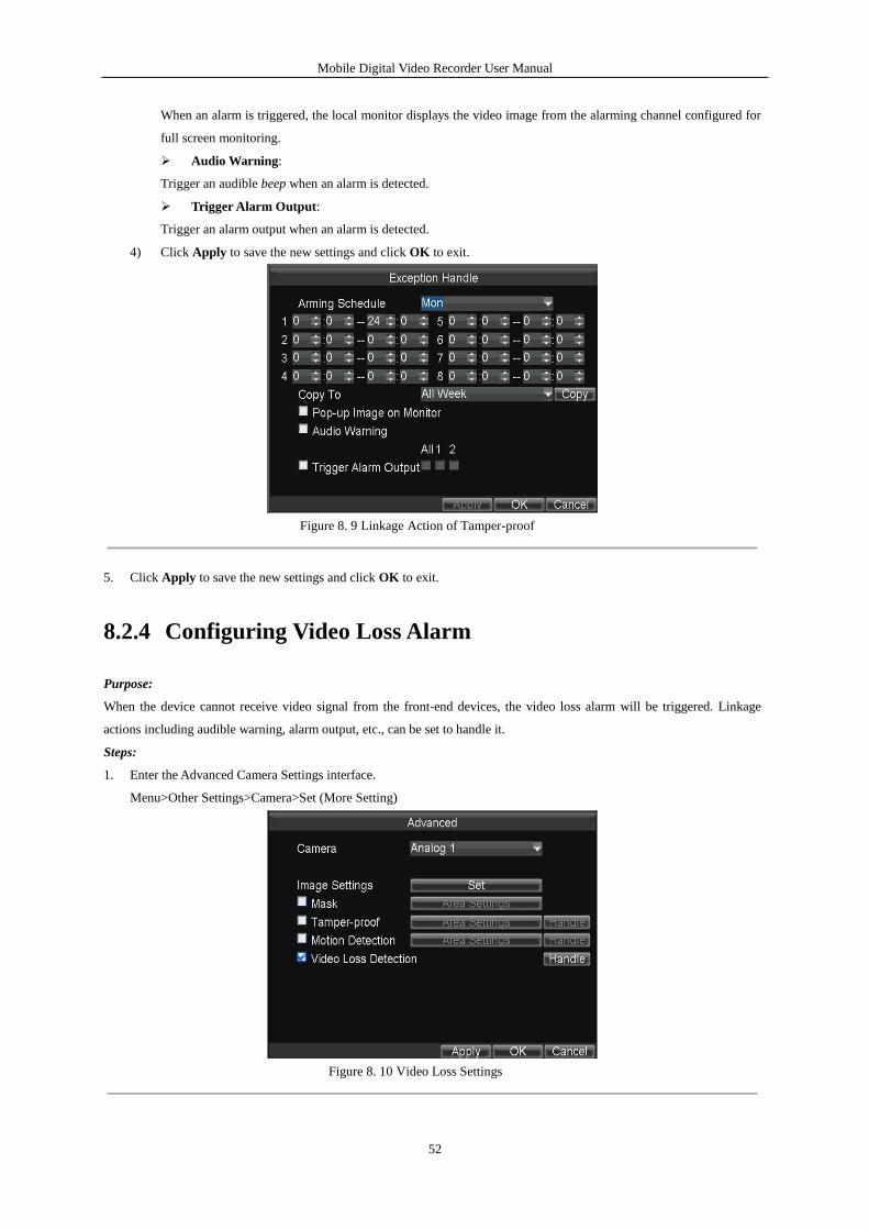
8.2.4 Configuring Video Loss Alarm
Purpose:
When the device cannot receive video signal from the front-end devices, the video loss alarm will be triggered. Linkage
actions including audible warning, alarm output, etc., can be set to handle it.
Steps:
1. Enter the Advanced Camera Settings interface.
Menu>Other Settings>Camera>Set (More Setting)
Figure 8. 10 Video Loss Settings
Mobile Digital Video Recorder User Manual
53
2. Check the checkbox of Video Loss Detection to enable the video loss detection settings.
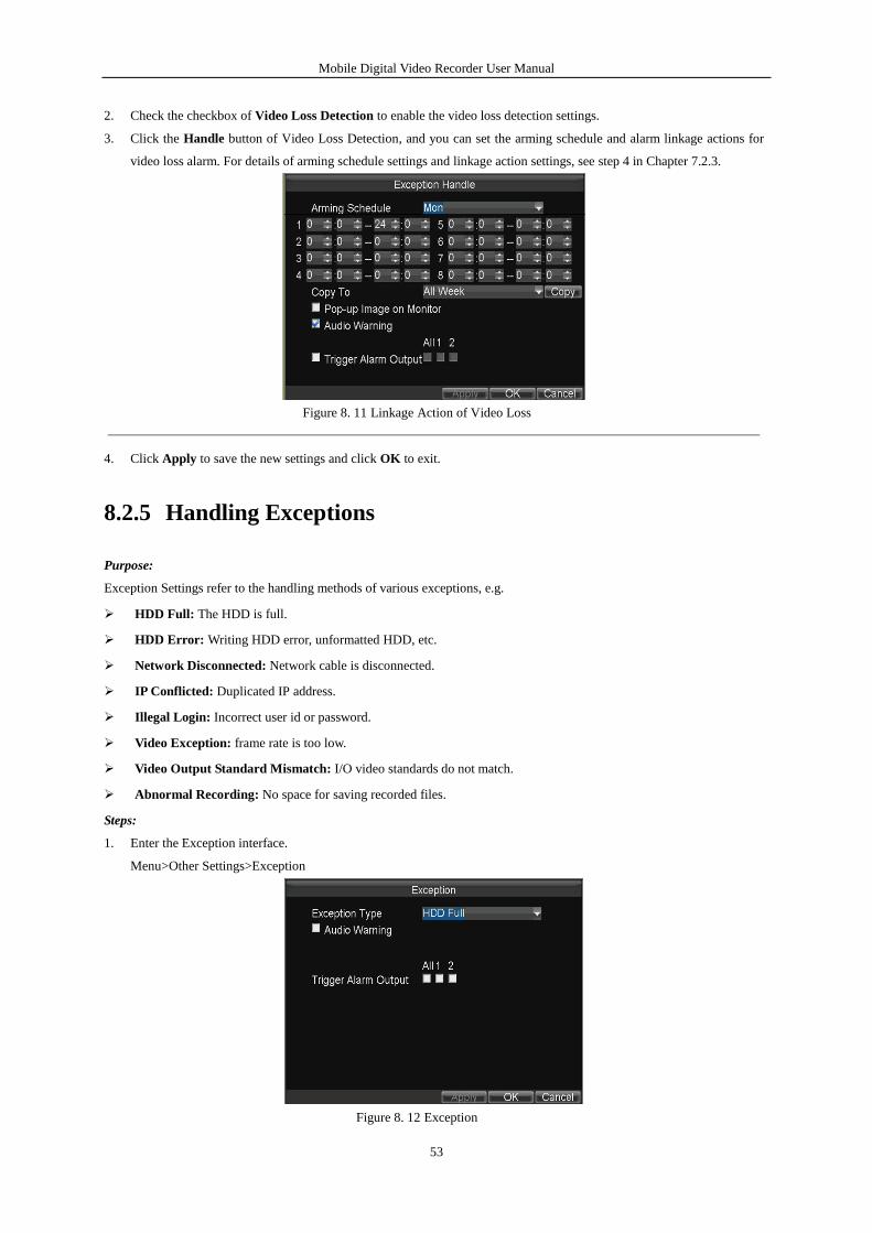
3. Click the Handle button of Video Loss Detection, and you can set the arming schedule and alarm linkage actions for
video loss alarm. For details of arming schedule settings and linkage action settings, see step 4 in Chapter 7.2.3.
Figure 8. 11 Linkage Action of Video Loss
4. Click Apply to save the new settings and click OK to exit.
8.2.5 Handling Exceptions
Purpose:
Exception Settings refer to the handling methods of various exceptions, e.g.
HDD Full: The HDD is full.
HDD Error: Writing HDD error, unformatted HDD, etc.
Network Disconnected: Network cable is disconnected.
IP Conflicted: Duplicated IP address.
Illegal Login: Incorrect user id or password.
Video Exception: frame rate is too low.
Video Output Standard Mismatch: I/O video standards do not match.
Abnormal Recording: No space for saving recorded files.
Steps:
1. Enter the Exception interface.
Menu>Other Settings>Exception
Figure 8. 12 Exception
Mobile Digital Video Recorder User Manual
54
2. Select the Exception Type and set the alarm linkage actions, including audible warning and alarm output.
3. Click Apply to save the new settings and click OK to exit.
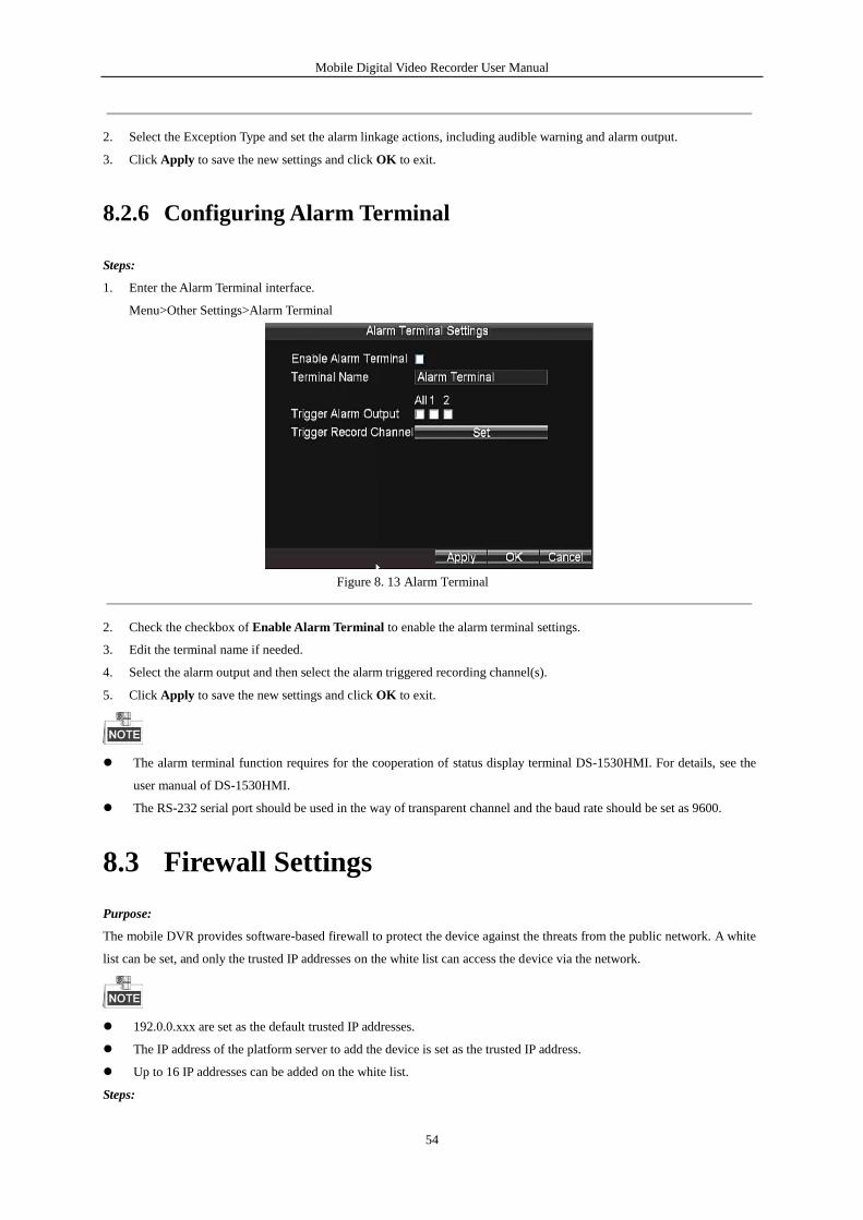
8.2.6 Configuring Alarm Terminal
Steps:
1. Enter the Alarm Terminal interface.
Menu>Other Settings>Alarm Terminal
Figure 8. 13 Alarm Terminal
2. Check the checkbox of Enable Alarm Terminal to enable the alarm terminal settings.
3. Edit the terminal name if needed.
4. Select the alarm output and then select the alarm triggered recording channel(s).
5. Click Apply to save the new settings and click OK to exit.
The alarm terminal function requires for the cooperation of status display terminal DS-1530HMI. For details, see the
user manual of DS-1530HMI.
The RS-232 serial port should be used in the way of transparent channel and the baud rate should be set as 9600.
8.3 Firewall Settings
Purpose:
The mobile DVR provides software-based firewall to protect the device against the threats from the public network. A white
list can be set, and only the trusted IP addresses on the white list can access the device via the network.
192.0.0.xxx are set as the default trusted IP addresses.
The IP address of the platform server to add the device is set as the trusted IP address.
Up to 16 IP addresses can be added on the white list.
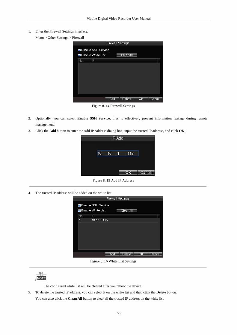
Steps:
Mobile Digital Video Recorder User Manual
55
1. Enter the Firewall Settings interface.
Menu > Other Settings > Firewall
Figure 8. 14 Firewall Settings
2. Optionally, you can select Enable SSH Service, thus to effectively prevent information leakage during remote
management.
3. Click the Add button to enter the Add IP Address dialog box, input the trusted IP address, and click OK.
Figure 8. 15 Add IP Address
4. The trusted IP address will be added on the white list.
Figure 8. 16 White List Settings
The configured white list will be cleared after you reboot the device.
5. To delete the trusted IP address, you can select it on the white list and then click the Delete button.
You can also click the Clean All button to clear all the trusted IP address on the white list.
Mobile Digital Video Recorder User Manual
56
8.4 Serial Port Settings
Purpose:
Two types of serial ports are provided: RS-232 and RS-485.
The RS-232 port can be used in two ways:
Console: Connect a PC to the DVR through the PC serial port. DVR parameters can be configured by using software
such as HyperTerminal. The serial port parameters must be the same as of the device when connecting with the PC
serial port.
Transparent Channel: Connect a serial device directly to the device. The serial device will be controlled remotely by
the PC through the network and the protocol of the serial device.
The RS-485 port can be used for transparent channel only.
Steps:
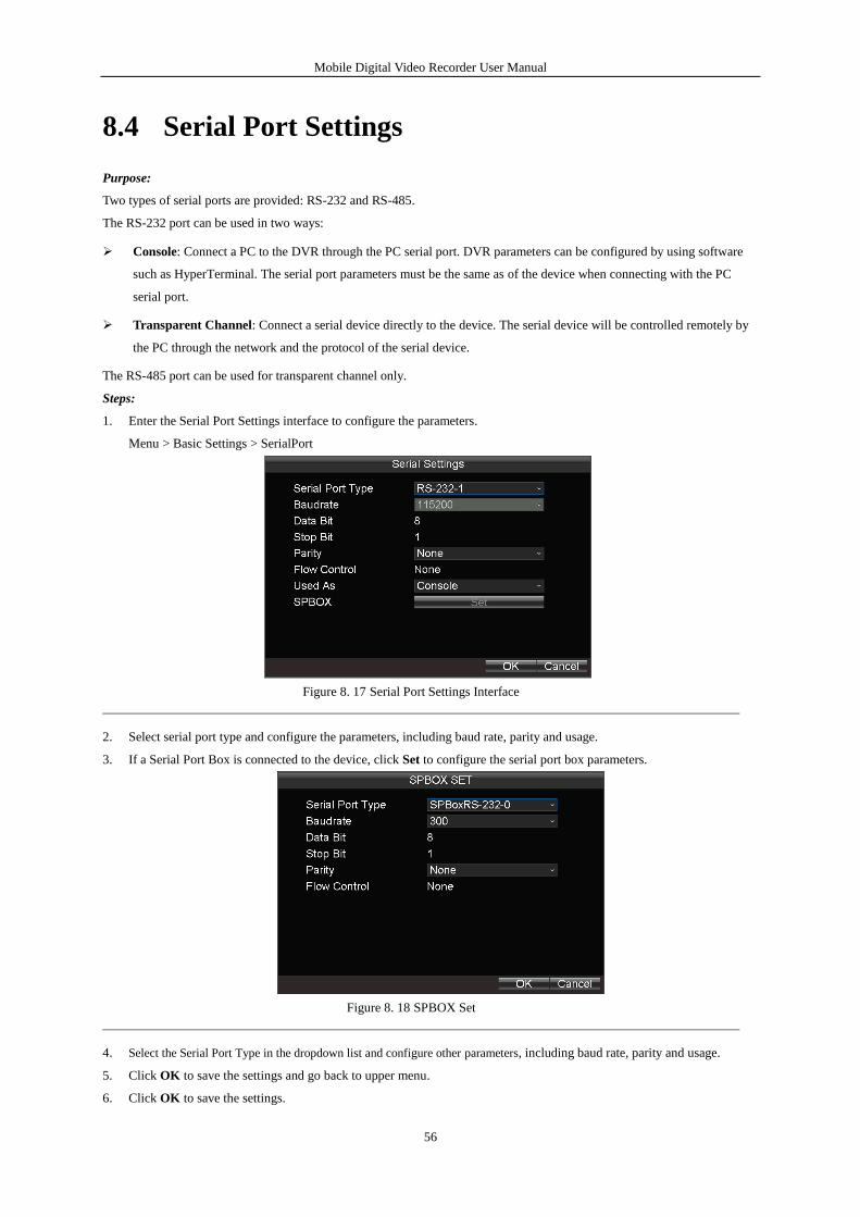
1. Enter the Serial Port Settings interface to configure the parameters.
Menu > Basic Settings > SerialPort
Figure 8. 17 Serial Port Settings Interface
2. Select serial port type and configure the parameters, including baud rate, parity and usage.
3. If a Serial Port Box is connected to the device, click Set to configure the serial port box parameters.
Figure 8. 18 SPBOX Set
4. Select the Serial Port Type in the dropdown list and configure other parameters, including baud rate, parity and usage.
5. Click OK to save the settings and go back to upper menu.
6. Click OK to save the settings.
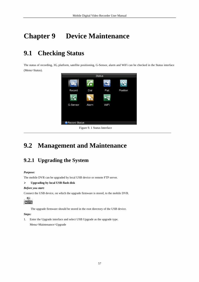
Mobile Digital Video Recorder User Manual
57
Chapter 9 Device Maintenance
9.1 Checking Status
The status of recording, 3G, platform, satellite positioning, G-Sensor, alarm and WiFi can be checked in the Status interface
(Menu>Status).
Figure 9. 1 Status Interface
9.2 Management and Maintenance
9.2.1 Upgrading the System
Purpose:
The mobile DVR can be upgraded by local USB device or remote FTP server.
Upgrading by local USB flash disk
Before you start:
Connect the USB device, on which the upgrade firmware is stored, to the mobile DVR.
The upgrade firmware should be stored in the root directory of the USB device.
Steps:
1. Enter the Upgrade interface and select USB Upgrade as the upgrade type.
Menu>Maintenance>Upgrade
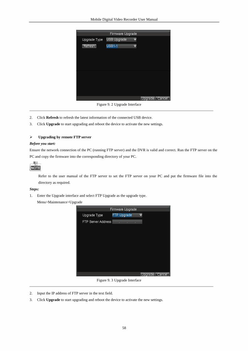
Mobile Digital Video Recorder User Manual
58
Figure 9. 2 Upgrade Interface
2. Click Refresh to refresh the latest information of the connected USB device.
3. Click Upgrade to start upgrading and reboot the device to activate the new settings.
Upgrading by remote FTP server
Before you start:
Ensure the network connection of the PC (running FTP server) and the DVR is valid and correct. Run the FTP server on the
PC and copy the firmware into the corresponding directory of your PC.
Refer to the user manual of the FTP server to set the FTP server on your PC and put the firmware file into the
directory as required.
Steps:
1. Enter the Upgrade interface and select FTP Upgrade as the upgrade type.
Menu>Maintenance>Upgrade
Figure 9. 3 Upgrade Interface
2. Input the IP address of FTP server in the text field.
3. Click Upgrade to start upgrading and reboot the device to activate the new settings.
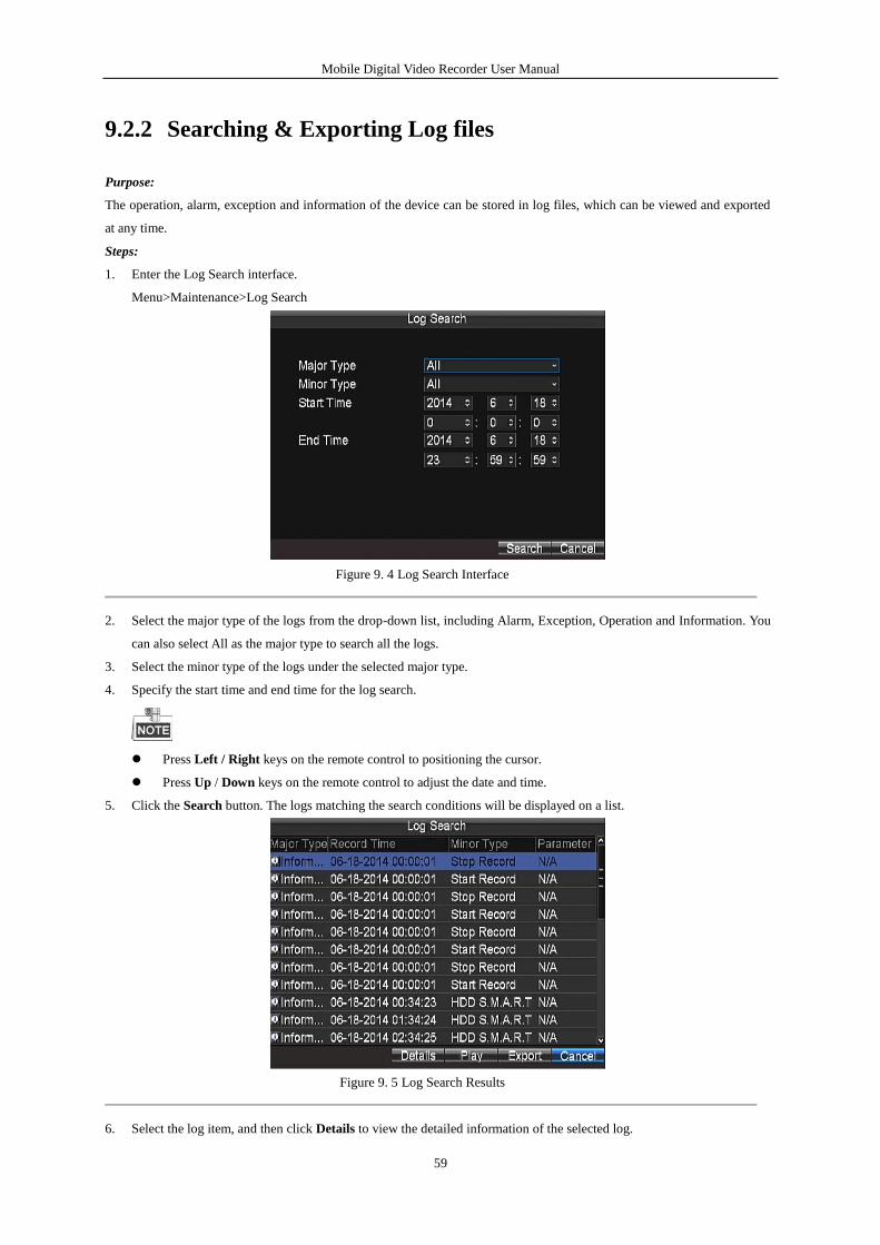
Mobile Digital Video Recorder User Manual
59
9.2.2 Searching & Exporting Log files
Purpose:
The operation, alarm, exception and information of the device can be stored in log files, which can be viewed and exported
at any time.
Steps:
1. Enter the Log Search interface.
Menu>Maintenance>Log Search
Figure 9. 4 Log Search Interface
2. Select the major type of the logs from the drop-down list, including Alarm, Exception, Operation and Information. You
can also select All as the major type to search all the logs.
3. Select the minor type of the logs under the selected major type.
4. Specify the start time and end time for the log search.
Press Left / Right keys on the remote control to positioning the cursor.
Press Up / Down keys on the remote control to adjust the date and time.
5. Click the Search button. The logs matching the search conditions will be displayed on a list.
Figure 9. 5 Log Search Results
6. Select the log item, and then click Details to view the detailed information of the selected log.
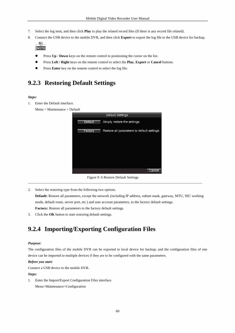
Mobile Digital Video Recorder User Manual
60
7. Select the log item, and then click Play to play the related record files (If there is any record file related).
8. Connect the USB device to the mobile DVR, and then click Export to export the log file to the USB device for backup.
Press Up / Down keys on the remote control to positioning the cursor on the list.
Press Left / Right keys on the remote control to select the Play, Export or Cancel buttons.
Press Enter key on the remote control to select the log file.
9.2.3 Restoring Default Settings
Steps:
1. Enter the Default interface.
Menu > Maintenance > Default
Figure 9. 6 Restore Default Settings
2. Select the restoring type from the following two options.
Default: Restore all parameters, except the network (including IP address, subnet mask, gateway, MTU, NIC working
mode, default route, server port, etc.) and user account parameters, to the factory default settings.
Factory: Restore all parameters to the factory default settings.
3. Click the OK button to start restoring default settings.
9.2.4 Importing/Exporting Configuration Files
Purpose:
The configuration files of the mobile DVR can be exported to local device for backup; and the configuration files of one
device can be imported to multiple devices if they are to be configured with the same parameters.
Before you start:
Connect a USB device to the mobile DVR.
Steps:
1. Enter the Import/Export Configuration Files interface.
Menu>Maintenance>Configuration
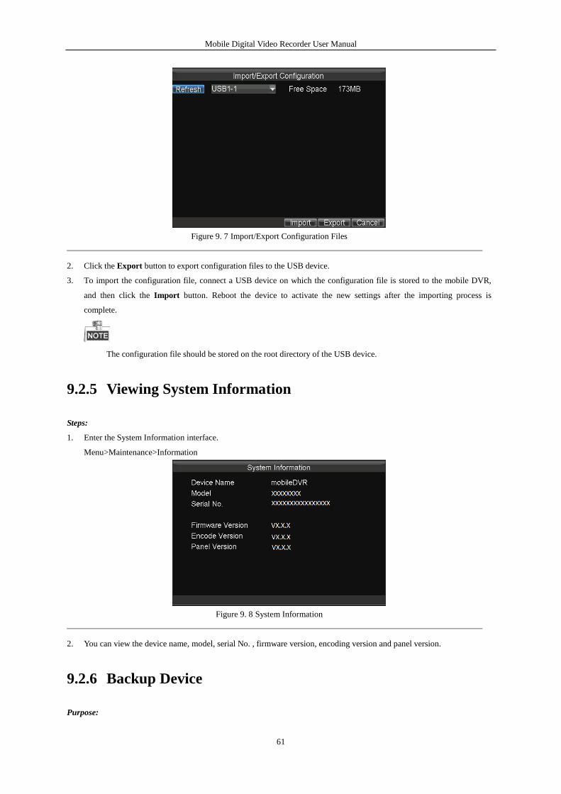
Mobile Digital Video Recorder User Manual
61
Figure 9. 7 Import/Export Configuration Files
2. Click the Export button to export configuration files to the USB device.
3. To import the configuration file, connect a USB device on which the configuration file is stored to the mobile DVR,
and then click the Import button. Reboot the device to activate the new settings after the importing process is
complete.
The configuration file should be stored on the root directory of the USB device.
9.2.5 Viewing System Information
Steps:
1. Enter the System Information interface.
Menu>Maintenance>Information
Figure 9. 8 System Information
2. You can view the device name, model, serial No. , firmware version, encoding version and panel version.
9.2.6 Backup Device
Purpose:
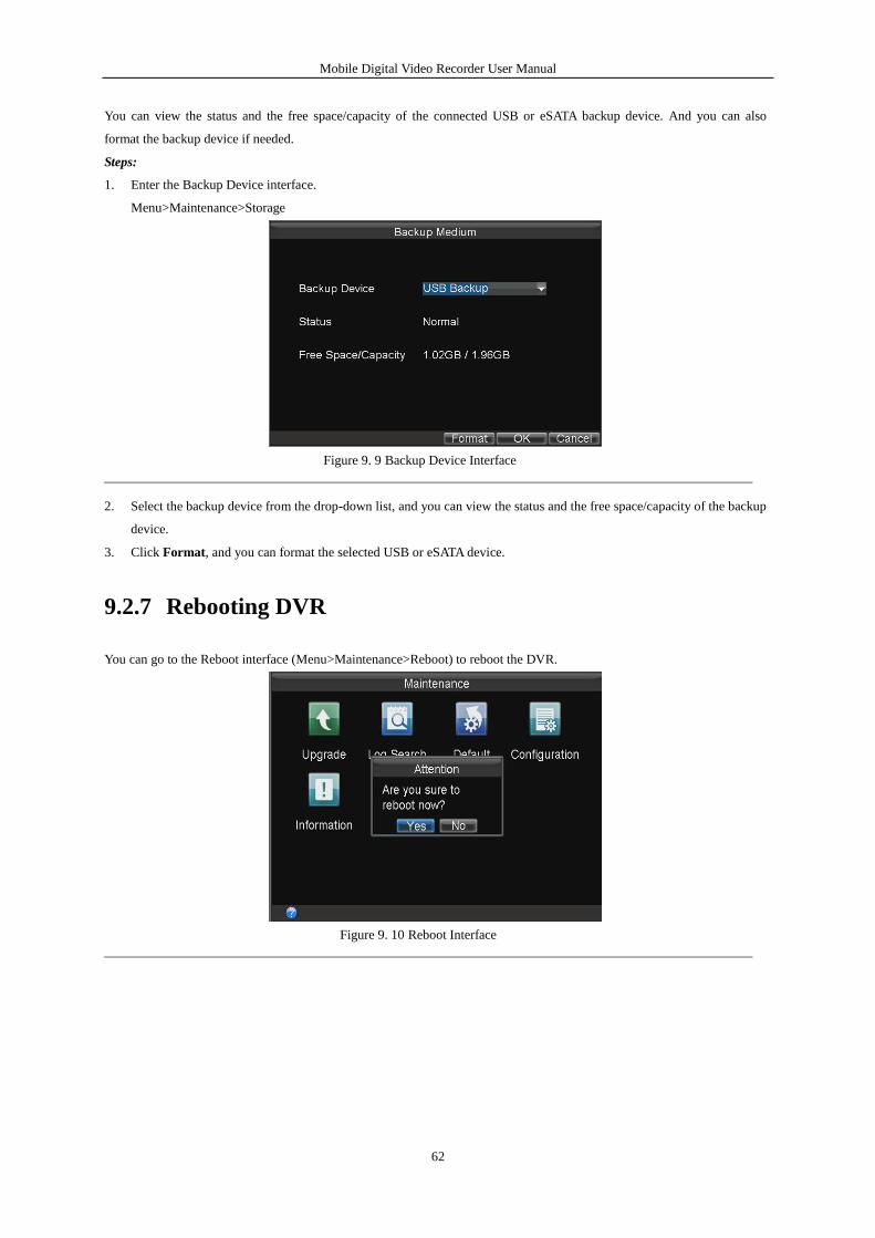
Mobile Digital Video Recorder User Manual
62
You can view the status and the free space/capacity of the connected USB or eSATA backup device. And you can also
format the backup device if needed.
Steps:
1. Enter the Backup Device interface.
Menu>Maintenance>Storage
Figure 9. 9 Backup Device Interface
2. Select the backup device from the drop-down list, and you can view the status and the free space/capacity of the backup
device.
3. Click Format, and you can format the selected USB or eSATA device.
9.2.7 Rebooting DVR
You can go to the Reboot interface (Menu>Maintenance>Reboot) to reboot the DVR.
Figure 9. 10 Reboot Interface
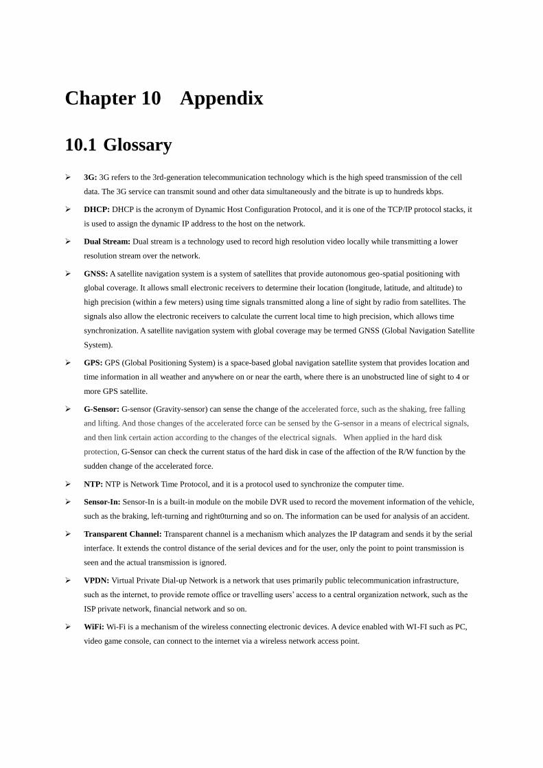
Chapter 10 Appendix
10.1 Glossary
3G: 3G refers to the 3rd-generation telecommunication technology which is the high speed transmission of the cell
data. The 3G service can transmit sound and other data simultaneously and the bitrate is up to hundreds kbps.
DHCP: DHCP is the acronym of Dynamic Host Configuration Protocol, and it is one of the TCP/IP protocol stacks, it
is used to assign the dynamic IP address to the host on the network.
Dual Stream: Dual stream is a technology used to record high resolution video locally while transmitting a lower
resolution stream over the network.
GNSS: A satellite navigation system is a system of satellites that provide autonomous geo-spatial positioning with
global coverage. It allows small electronic receivers to determine their location (longitude, latitude, and altitude) to
high precision (within a few meters) using time signals transmitted along a line of sight by radio from satellites. The
signals also allow the electronic receivers to calculate the current local time to high precision, which allows time
synchronization. A satellite navigation system with global coverage may be termed GNSS (Global Navigation Satellite
System).
GPS: GPS (Global Positioning System) is a space-based global navigation satellite system that provides location and
time information in all weather and anywhere on or near the earth, where there is an unobstructed line of sight to 4 or
more GPS satellite.
G-Sensor: G-sensor (Gravity-sensor) can sense the change of the accelerated force, such as the shaking, free falling
and lifting. And those changes of the accelerated force can be sensed by the G-sensor in a means of electrical signals,
and then link certain action according to the changes of the electrical signals. When applied in the hard disk
protection, G-Sensor can check the current status of the hard disk in case of the affection of the R/W function by the
sudden change of the accelerated force.
NTP: NTP is Network Time Protocol, and it is a protocol used to synchronize the computer time.
Sensor-In: Sensor-In is a built-in module on the mobile DVR used to record the movement information of the vehicle,
such as the braking, left-turning and right0turning and so on. The information can be used for analysis of an accident.
Transparent Channel: Transparent channel is a mechanism which analyzes the IP datagram and sends it by the serial
interface. It extends the control distance of the serial devices and for the user, only the point to point transmission is
seen and the actual transmission is ignored.
VPDN: Virtual Private Dial-up Network is a network that uses primarily public telecommunication infrastructure,
such as the internet, to provide remote office or travelling users’ access to a central organization network, such as the
ISP private network, financial network and so on.
WiFi: Wi-Fi is a mechanism of the wireless connecting electronic devices. A device enabled with WI-FI such as PC,
video game console, can connect to the internet via a wireless network access point.
Mobile Digital Video Recorder
64
10.2 FAQ
• Why does my DVR make a beeping sound after booting?
The possible reasons for the warning beep on the device are as follows:
a) There is no hard disk installed in the device.
b) The hard disk is not initialized.
c) Hard disk error
To cancel the beeping sound and use the device without any hard disks, enter the Exception Settings interface. For detailed
information, see Chapter 7.2.5 Handling Exceptions.
• DVR fails to start up after connecting the power.
Possible reasons:
a) Incorrect voltage input (6 ~ 36 VDC) and power consumption (≥ 50W).
b)The power connections are incorrect and please refer to Chapter 1.3.
c) The motherboard or power functions abnormally. In case of hardware failure, please contact the supplier of the
product.
• Fail to connect 3G.
Possible reasons for 3G connection failure are as follows:
a) Dialing is not enabled.
b)APN, dial number, user name and password should be set for 3G VPDN private network.
c) No 3G antenna connected. When both the master/slave antennas are connected, locate them vertically with above
20cm distance from each other.
d)SIM card is out of service or 3G service is not opened.
• Fail to connect to Wi-Fi.
Please check the following settings:
a) The SSID, encryption type or password are entered incorrectly.
b)AP (access point) or router works abnormally.
c) No Wi-Fi antenna connected or the antenna is not vertically located.
• The DVR cannot be accessed via platform (iVMS) after successful connection to 3G or Wi-Fi.
Possible reasons:
a) The parameters (e.g., server IP, device registered ID, etc.) of the platform are configured incorrectly.
b)The platform works abnormally.
• Fail to obtain satellite positioning information.
Possible reasons:
a) The satellite positioning antenna is not placed outdoor.
b)There is no satellite positioning module (built-in or external) available for the DVR.
Mobile Digital Video Recorder
65
c) The Position Module are configured incorrectly (please see Chapter 6.2).
• Why does the device seem unresponsive when operating with the IR remote control?
Please read Chapter 1.3, and check:
a) The batteries are installed correctly, making sure that the polarities of the batteries are not reversed.
b) The batteries are fresh and are not out of power.
c) The remote sensor is not covered or blocked by other object.
d) There are no fluorescent lamps in use nearby.
• No backup device is detected when exporting recorded files?
Possible reasons:
a) There is no backup device connected with the DVR.
b)The DVR and your backup device are not compatible.
c) Initialize the backup device before using.
d)The backup device is damaged.
0400021050807
User Manual of Mobile Digital Video Recorder
66