mobile climbing wall identification - ecievents.net manuals/climbing wall manual - low r… · this...
TRANSCRIPT

Mobile Climbing Wall Identification
Product Name: _____________________________________________________ Model: ____________________________________________________ Specialty Items: _____________________________________________ Serial Number: ______________________________________________ VIN Number: ________________________________________________ Date Manufactured: __________________________________________ Company Name: ____________________________________________ Customer Name: ____________________________________________ Phone Number: _____________________________________________ Address: ___________________________________________________ ___________________________________________________
720 West 200 South Logan, Utah 84321
888-563-0163

2
CHANGE OF OWNER/OPERATOR FORM
Original Owner of Wall: Company Name: _______________________________________________________ Contact name (s): _______________________________________________________ Bill to Address: __________________________________________________________ City: _______________________ State: ______________ Zip: _________________ Phone: ________________ Alt. Phone: _________________ Fax: _______________ Former Wall Location: ___________________________________________________ City: __________________________ State: ___________ Zip: _________________ Date Sold: _______________________________ New Owner/Operator Information: Company Name: ________________________________________________________ Contact name (s): _______________________________________________________ Bill to Address: __________________________________________________________ City: ______________________________ State: ________ Zip: _________________ Phone: _________________ Alt. Phone: _________________ Fax: ______________ Wall Location: __________________________________________________________ City: ___________________________ State: ____________ Zip: _________________ Wall Information: CND DAR Mobile Stationary 24’ 32’ Other: __________________ Serial # ______________________________ VIN # _______________________________ Year: ________________________________
*Please mail or fax to: Spectrum Sports International 720 West 200 South Logan, Utah 84321 Attn: Attn: Marsha Fax: (435) 792-3884 Phone: (888) 563-888-563-0163 (Toll Free)
3
ClimbNdangle/DropARock
Operations Manual
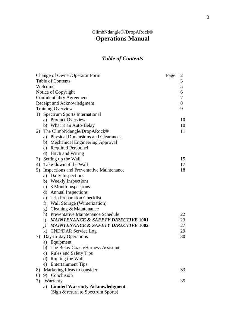
Table of Contents
Change of Owner/Operator Form Page 2 Table of Contents 3 Welcome 5 Notice of Copyright 6 Confidentiality Agreement 7 Receipt and Acknowledgment 8 Training Overview 9 1) Spectrum Sports International
a) Product Overview 10 b) What is an Auto-Belay 10
2) The ClimbNdangle/DropARock 11 a) Physical Dimensions and Clearances b) Mechanical Engineering Approval c) Required Personnel d) Hitch and Wiring
3) Setting up the Wall 15 4) Take-down of the Wall 17 5) Inspections and Preventative Maintenance 18
a) Daily Inspections b) Weekly Inspections c) 3 Month Inspections d) Annual Inspections e) Trip Preparation Checklist f) Wall Storage (Winterization) g) Cleaning & Maintenance h) Preventative Maintenance Schedule 22 i) MAINTENANCE & SAFETY DIRECTIVE 1001 23 j) MAINTENANCE & SAFETY DIRECTIVE 1002 27 k) CND/DAR Service Log 29
7) Day-to-day Operations 30 a) Equipment b) The Belay Coach/Harness Assistant c) Rules and Safety Tips d) Routing the Wall e) Entertainment Tips
8) Marketing Ideas to consider 33 6) 9) Conclusion 7) Warranty 35
a) Limited Warranty Acknowledgment (Sign & return to Spectrum Sports)

4
Appendices Appendix A CND/DAR Engineering Stamp of Approval 40
Appendix B Wiring Schematic for Breakaway Switch 41 Appendix C ASTM Recommended Injury and Illness Reporting 43 Appendix D Trouble Shooting Guide 46 Appendix E CND/DAR Accessories & Parts Order Form 48 Appendix F Wiring Schematic for Mobile Transportation 51 Appendix G Auto-Belay Cylinder Replacement Instructions 52
� Auto-Belay Diagram Appendix H Cable Replacement Instructions 55
� Cable Threading Diagram Appendix J Trailer Jack Information Sheet 58

5
Welcome It is with great pleasure that I congratulate you on your ClimbNdangle or DropARock purchase and welcome you to Spectrum Sports International (SSI). We are excited about our products and feel confident that through proper planning, placement and hard work, the ClimbNdangle/DropARock will be a rewarding and profitable purchase. Our philosophy is centered on a commitment to excellence in meeting the needs of our customers, providing a quality product that is safe, exciting and profitable. We encourage you to likewise develop a standard of quality and service that makes you the leader in supplying artificial climbing walls for the amusement, entertainment and special attractions market. Our part in making our team successful is: � Commitment to proper, effective and profitable design. Each of our products is
stamped by a certified engineer, which means that you can rest assured you have purchased a product that will be safe.
� Manufacturing to “ASTM F-24” safety standards for the amusement industry. Why is this important? Because it demonstrates our commitment to design, operations and most importantly, safety!
� Testing designs before the sale � Maximum customer throughput generating high profits � Experience in the industry, from large amusement parks to birthday rental
entrepreneurs. � All manufacturing is done in-house, which provides for exceptional Quality Control. Your part in building a successful business using Spectrum Sports International products is: � Commitment to safe operation � Consistent inspection for proper maintenance � Effective and active marketing and promotion We are looking forward to a long and prosperous relationship. Should you have any comments or questions, please do not hesitate in calling. Sincerely, Spectrum Sports Team

6
Copyright 1996 – 2004 Spectrum Sports International. Reproduction or translation of any part of this work beyond that permitted by Section 107 or 108 of the 1976 United States Copyright Act without permission of the copyright owner is unlawful. Requests for permission or further information should be addressed to Spectrum Sports International.
7
Confidentiality Agreement
This manual and the content within this manual are for the exclusive use and operation of the ClimbNdangle and DropARock product, by the owner of the respective product and its authorized personnel and for Spectrum Sports International. This manual is designed to provide accurate and authoritative information in regard to the subject matter covered. This manual may not be reproduced in whole or part in any form or by any means, without the prior written consent of Spectrum Sports International. Confidentiality
This manual contains proprietary information belonging to Spectrum Sports International. It is to be viewed only by persons employed by Spectrum Sports International and/or the ClimbNdangle or DropARock owner and authorized personnel.
Distribution
This manual is not to be distributed to any other persons other than those actively engaged in the operating and/or marketing of the ClimbNdangle/DropARock product and customers serviced by the owner of the ClimbNdangle/DropARock climbing wall.
Disposition
This manual is the property of the ClimbNdangle/DropARock owner and Spectrum Sports International and must be discarded or returned to Spectrum Sports International upon receipt of an updated manual.
Revision
Spectrum Sports International may make periodic additions, deletions and modifications to this manual at any time with out prior notification. These updates will, in the judgment of Spectrum Sports International, add to the quality of services offered.
Notice Of Changes
In the event that revisions are made to this manual, Spectrum Sports International will send the appropriate pages reflecting such changes as are deemed necessary and a revised document will be issued to the individual for replacement. Any pages that are then outdated must be destroyed and discarded.
In the event that replacement pages are sent, Spectrum Sports International will provide a cover letter outlining the revision and the effective date of any procedural changes.

8
Receipt and Acknowledgment
This Operations Manual is an important document intended to help you become acquainted with the ClimbNdangle/DropARock, Spectrum Sports International and includes guidelines as to safe and recommended operation. Please read the following statement. Respond to Spectrum Sports International in writing with any questions or if the intent of this document is unclear.
As an owner, I have received and read my copy of the ClimbNdangle or DropARock Spectrum Sports Internationa Operations Manual. I understand that the information outlined in this manual is subject to change at the sole discretion of Spectrum Sports International at any time. As an owner of the ClimbNdangle/DropARock or authorized representative, it is my responsibility to keep this manual up-to-date with any changes that are made by Spectrum Sports International.. In addition, if there is anything about the product and/or this manual that is unclear or not understood, it is my responsibility to seek clarification and not use the product until the issue is understood.
Unless informed in writing, Spectrum Sports International assumes that the customer understands the ClimbNdangle/DropARock product and that there are no questions regarding the product and/or the contents of this document. It is the customer’s sole responsibility to clarify any question or concern with Spectrum Sports International before use and/or operation.

9
Training Overview
This manual is an introduction to the ClimbNdangle/DropARock and its operation. The purpose of this manual is to provide a compilation of information that will assist you in proper and safe operation. The philosophy of Spectrum Sports International is centered on a commitment to excellence in meeting the needs of its customers and associates by providing them with the enclosed information. The manual is designed to provide the wall owner with the information, tips, and techniques that will help the owner and employees operate the wall as effectively and safely as possible. This manual is no way a total representation of all facts. Safe operation of this product is the sole responsibility of the wall owner/operator. Good and reasonable judgment must be used when traveling, promoting and/or operating the wall.

10
Product Overview
ClimbNdangle & DropARock - Welcome to the ClimbNdangle/DropARock product. As the originators and inventors of the Auto-Belay, Spectrum Sports’ products are industry leaders in innovation, safety, design and customer satisfaction. Designed for the amusement, entertainment, and recreation industries, Spectrum Sports International products are engineered with safety, customer appeal and customer throughput in mind. Complete with the first redundant Auto-Belay device, the ClimbNdangle/DropARock maximizes profit and safety. Different from other Climbing Walls, the ClimbNdangle and DropARock do not use, what is commonly termed as a belayer (a person who controls the rate of decent of a climber). The reason for this is because of the Auto-Belay devices. With the Auto-Belay devices doing all of the belay work and ensuring safety, the person(s) operating the wall act more like a coach offering encouragement and direction. The ClimbNdangle/DropARock is designed to meet ASTM F-24 standards for the Amusement Industry. In addition, upon request, each unit can be inspected by a third party C.W.I.(Certified Welding Inspector). This means that the ClimbNdangle/DropARock is designed, manufactured, tested, and supported by comprehensive quality assurance and quality control measures to ensure product reliability and safety. The enclosed information is an outline as to the procedures for safe operation and set-up of the product.
What is an Auto-Belay? The Belay - In order to understand the term Auto-Belay, we must first define the term belayer respective to traditional rock-climbing. The act of belaying can be defined as a procedure of securing a climber by the use of a rope. In recreational sport climbing there are generally two people involved in a climb. A climber, the person climbing the intended surface or structure, and the Belayer, the person who is providing the safety for the climber. The belayer’s role is to use two hands on a braking device, which controls the descent of the climber. One of the functions of the belayer is to ensure the rope is stacked carefully to prevent the rope from tangling which would result in the climber dangling. Once the climber asks to come down, it is the function of the belayer to allow the rope to pass through the braking device such that the climber descends at a rate that is not too fast or too slow. The biggest fears in manually lowering someone as a belayer, is that a belayer could drop the climber out of control, or let the end of the rope pass through the belay device such that the climber falls to the ground. Both of these mistakes have often happened, and to very experienced climbers. Auto-Belay - Spectrum Sports International is using the term “Auto-Belay” to describe its automated belaying process. Rather than a person acting as the belayer, SSI has developed an air/oil hydraulic system that automatically controls the rate of descent when a climber falls or chooses to come down off the wall. The function of the automated belaying system is to take up the climbing cable as the person climbs. As a climber

11
climbs the wall, the climber will take weight off of the cable, in which the positive air pressure in the hydraulic system causes the cable to retract or to functionally take up the cable slack. The Auto-Belay system by SSI has developed a system that automates this function. Spectrum Sports’ automated system eliminates the need to rely upon a human belayer for every climber, rather; it allows a single person (belayer) to supervise all climbers ensuring safe and proper climbing. So, with all this said, the Auto-Belay system simply allows a climber to climb the wall without the need of a human belayer. The ClimbNdangle/DropARock, with its Auto-Belay devices, allows for three/four climbers to climb the wall simultaneously with only one person acting as a belaying coach. Whereas in traditional rock climbing, every climber requires a belayer. This simple feature means that when operating a wall for profit, the ClimbNdangle/DropARock generates more profit than a wall requiring human belayers by simply reducing the amount of labor needed to operate the wall.
ClimbNdangle & DropARock The names ClimbNdangle and DropARock are the product names for each products entire system (i.e. Climbing wall and Auto-Belay safety system). The mobile units have been designed to travel down the road in a down/closed fashion. Aerodynamic because of its hallow shape, the mobile units travel relatively easy. As a reminder, please follow any and all rules established by a state or interstate highway system that you would travel in the course of conducting your business or transport of the product. Please abide by all traffic laws and warnings. There are five styles of mobile units: 1) Standard Trailer (single axle & dual axle) 2) Folding Trailer (dual axle) 3) 32’ Mobile 5th Wheel
4) 32’ Tongue-Pull Folding Trailer 5) 32’ Tongue-Pull Non-Folding Trailer
“Drop & Go” optional package (steel bracing), which can be added to either standard or folding trailers, which will make it a stationary/mobile combination Physical Dimensions – The dimensions for both the CND and DAR mobile products are: ClimbNdangle 24’ Mobile � Width – 8’ – 8” � Travel Height – 8’ – 6” � Length – 28’ – 10” � Standard Trailer when standing vertical – 9’ 7” (Width), 28’ 10” (Length), 24’ 6”
(Height) � Folding Trailer when standing vertical – 9’ 7” (Width), 15’ 8” (Length), 24’ 6”
(Height) � Standard Weight – 3,800 lbs. � Folding Trailer Weight – 4,000 lbs.
12
DropARock 24’ Mobile � Travel Width – 7’ – 6” � Travel Height – 9’ – 1” � Travel Length – 28’ – 10” � Standard Trailer when standing vertical – 9’ 7” (Width), 28’ 10” (Length), 24’ 6”
(Height) � Folding Trailer when standing vertical - 9’ 7” (Width), 15’ 8” (Length), 24’ 6”
(Height) � Standard Weight – 4,300 lbs. � Folding Trailer Weight – 4,800 lbs. * When raising a 24’ wall, a minimum ceiling height of 26’ is required due to the length of the davit at the top of the wall.
DropARock 32’ Folding Mobile � Travel Width – 7’ – 6” � Travel Height – 9’ – 1” � Travel Length – 38’ – 0” � Folding Trailer when standing vertical - 12’ (Width), 20’ 11” (Length), 32’ 5”
(Height) � Folding Trailer Weight – 7400 lbs. � 32’ Folding Trailer when standing vertical – 10’ (Width), 20’ 11” (Length), 32’ 5”
(Height) � 32’ 5th wheel option – 7,000 lbs. � 32’ Tongue Pull/Folding Tongue Trailer – 7400 lbs. * When raising a 32’ wall, a minimum ceiling height of 34’ is required due to the length of the davit at the top of the wall. *Spectrum Sports International reserves the right to change any part(s) of described products without prior customer notifications. 24’ ClimbNdangle/DropARock folding trailer options: 1. ClimbNdangle/DropARock mobile using the trailer in travel position (straight trailer).
The footprint area needed for function, is apx 28’ long and 10’ wide, with an additional 8’ – 8’ needed in front of the wall climbing surfaces for belay area (referred to as “safety zone”).
2. ClimbNdangle/DropARock mobile using the folding option; the trailer has been hydraulically raised. The footprint is 14’ long by 10’ wide, with an additional 8’ – 8’ needed in front of the wall climbing surfaces for safety zone.
3. ClimbNdangle/DropARock mobile with trailer removed. The footprint will be 9’ long/deep by 8’ wide, with an additional 8’ – 8’ needed in front of the wall climbing surfaces for safety zone.
13
24’ ClimbNdangle/DropARock non-folding trailer opti ons: 1. ClimbNdangle/DropARock mobile using the trailer in travel position (straight trailer).
The footprint area needed for function, is apx 28’ long and 10’ wide, with an additional 8’ – 8’ needed in front of the wall climbing surfaces for belay area (referred to as “safety zone”).
2. ClimbNdangle/DropARock mobile with trailer removed. The footprint will be 9’ long/deep by 8’ wide, with an additional 8’ – 8’ needed in front of the wall climbing surfaces for safety zone.
Mechanical Engineering Approval – The ClimbNdangle/DropARock have been designed and reviewed by engineers that stand behind the ClimbNdangle/DropARock design. If it is necessary that you receive a copy of the engineering analysis, SSI will provide a copy contingent upon the signing of a “non-disclosure/non-compete agreement”. Please call Spectrum Sports InternationalInternational for details and pricing. * CUSTOMER IS RESPONSIBLE FOR FINDING WHAT CURRENT CODES ARE REQUIRED TO OPERATE PRODUCT WITHIN THEIR STATE.
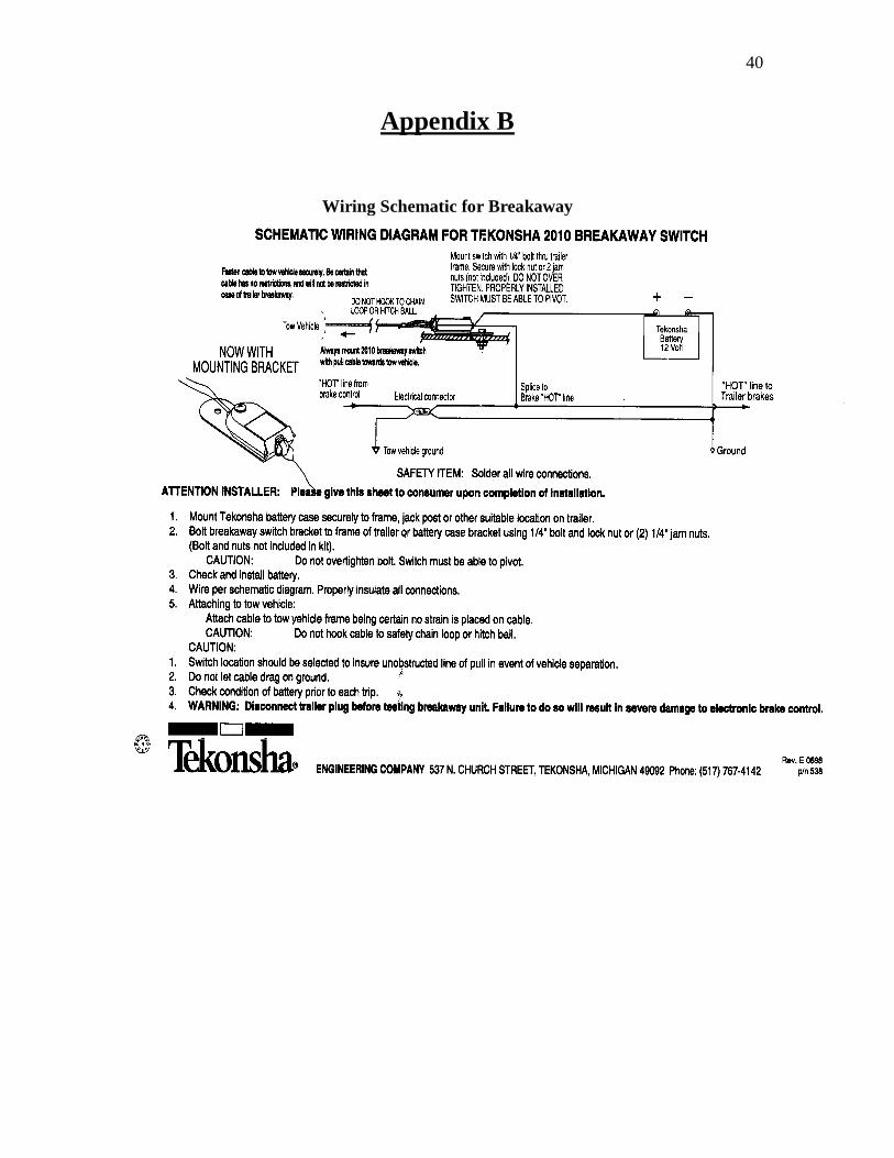
Required Personnel - The ClimbNdangle/DropARock can be operated with only one person. However, for efficient operations, SSI recommends that at least two people operate the attraction for optimal performance and safety. Spectrum Sports International recommends that one-person act as the climbing coach, supervising any one or all of the climbers and a second person to harness the climber and obtain a parental consent or hold harmless signature. The climbing coach should offer encouragement, entertain the climber and most importantly watch the belay cable to ensure that there is no excess slack in the cable or that the climber does not out climb the Auto-Belay device. The second person in charge of harnessing should ensure the harness is worn correctly. Hitch and Wiring - To pull the ClimbNdangle standard, single-axle, you will need a 2-inch ball on your vehicle and a female seven - (7) prong-wiring plug (See Appendix F) for wiring. For the DropARock or dual-axle ClimbNdangle, you will need a 2-5/16” ball and a female seven-prong-wiring plug. Remember that your tow hitch must be equipped with an electric trailer brake control. As a note, if you only use your unit for close proximity/cross town type attractions/events, it may be necessary to charge your battery with a 12 V car style battery charger. The ability to raise and lower the wall from the trailer depends upon the battery being fully charged. Short trips will NOT be sufficient to fully charge your battery off the vehicle. Not having a fully charged battery will affect the raising and lowering of the wall. In the event that there is insufficient power to raise/lower the wall, you may need to use jumper cables from a towing vehicle or some type of battery charger. Please note that your receiving “female” electrical connection on your vehicle must terminate as close to the hitch as possible. The “male” pigtail of the trailer is a perfect length for the appropriate turn radius without dragging on the ground. However, if the connection is anywhere other than next to the actual hitch, the pigtail may not be long enough to reach. Refer to Appendix B for Wiring Schematic for the Breakaway Switch.

14
Setting up the Wall
We highly recommend setting up your wall on a flat surface before your first event, to be come familiar with the set up procedure. Remove all shrink-wrap from the factory that is on the Auto-Belay cables inside and at the top of wall. Your wall can be set up on surfaces that have been compacted, blacktop, concrete, established lawns, etc. Do not set up wall if current winds exceed 35mph or a storm is approaching. Make sure the desired location is free from overhead obstacles, utility lines/cables or any other obstacle(s) as the wall is being raised. You need another 18" above the climbing wall to clear the davits as the wall is being raised.
• Check air pressure in all Auto-Belay tanks by looking at pressure gauge (see Auto-Belay Diagram). This should be the first thing to check, it’s easier to add air while the wall is horizontal.
• Disconnect trailer from towing vehicle. • Remove tie down strap from front of wall. • Pull all belay cables down the front of the wall and attach them to the anchor bolts
on the bottom of wall panel, or with one cable down you can climb up the wall and retrieve the other belay cables, one at a time.
• Pull pin and extend jacks out so the holes in trailer and jack arms align. Reinsert pin in hole.
• Pull jackleg pin so the leg drops to the ground. You may have to lift leg up for the holes to align. Reinsert pin.
• Turn the jack handle so it starts to lift the trailer and then go to another jack and repeat until the entire trailer had been raised 4" off the ground. This is to ensure that the metal base of the wall does not drag on surface while being raised. This is the most time consuming procedure but is important so the individual jack is not being side loaded, which will shear the roll pin inside.
• If you have a non-folding trailer, the use of the drop jack is necessary to keep the trailer supported as the wall is being raised. You will need shims (pieces of plywood or something similar) beneath the leg of the drop jack.
• If you have a folding trailer, you need to remove the bolts on the bottom of the trailer (under the hinged/folding area). Remove any extras that you may have added to the tongue of the trailer before raising the wall. Press the “Trailer/Tongue UP” button on the remote and hold until the tongue is at a 90° angle. Disconnect remote from trailer.
• Level the trailer from front to back and side-to-side, this is important for the base of the wall when it is vertical, if needed, add shims under the base of the wall to stabilize wall on uneven surfaces.
• Remove cover cap from pendant (remote) plug socket, which is located on the driver’s rear side of trailer. Carefully insert the yellow pendant (remote) plug end into socket; it will only go on one way. Be careful not to force plug into socket, the pins are small and can break off. Secure plug by threading black ring into plug socket.
15
• Press the “UP” button and hold it down the entire time as the wall is being raised. If you have to stop while raising the wall, wait until the wall stops moving before you restart. Once again, make sure there is proper clearance for the arc of the wall before raising the wall.
• Release the “UP” when the wall is 90 degrees to the trailer. You can make fine adjustments to the wall but wait until wall stops moving in between adjustments.
• Lower the entire trailer by the use of all the jacks so the base of the wall (steel base, not fiberglass base) is flat against the surface. Remember to rotate from jack to jack so not to put a side load onto jacklegs. The weight of the wall needs to rest on the metal triangle frame on the base of the wall.
• The use of shims might be needed to compensate for irregular surfaces. Shim ONLY the metal frame, not the fiberglass panel. This will greatly add to the stability of the wall.
• While holding onto a belay cable, unlock the carabineer and allow the cable to retract overhead (not letting go of the cable) and then pull it to the ground. This is referred to as “priming” the system to remove any air pockets or bubbles from the hydraulic hoses. Repeat this until you feel constant resistance on the down stoke. This procedure will have to be performed each time the wall is raised to eliminate air from belay cylinders. Repeat this procedure with each of the belay cables. We recommend you climb each of the routes at least once to make sure that each belay cable has constant resistance.

16
Take Down of the Wall
At the end of an event or use of the wall, please take the following steps to ensure safe and proper takedown of the wall.
• Raise the steel base of the wall off the ground 2 inches using the trailer jacks. • Connect the remote control to wall. • Ensure that it is safe to lower the wall, making sure there are no overhead
obstructions in the arc path. Press and hold the “Down “ button the entire time the wall is lowering. If you have to stop while lowering the wall, wait until the wall stops moving before you restart.
• You want to release the “Down” button when the wall is firmly on the front catch. After the wall is completely down do not continue to hold the “Down” button, it will cause the lifting cylinder to completely retract pulling the trailer and wall together.
• Attach the tie-down strap from the front of the wall to the front catch and ratchet it tight.
• Lower the trailer, making sure to rotate from jack to jack until the tires are resting on the surface. If you have a non-folding trailer, raise the drop jackleg first, in front of fenders.
• Pull jackleg pin, raise the jackleg to the highest pinhole and insert pin. Continue to fully raise the jackleg to the highest possible position. Stop turning jack handle when you feel resistances.
• Pull jack arm pin and slide in jack towards trailer. Align both holes and insert pin to hold jack during traveling.
• Attach towing vehicle to trailer and insert hitch closure pin and secure hitch. • When attaching the safety chains to towing vehicle, crisscross them to form an
“X”. • Secure trailer plug. • As always, make sure to obey all traffic laws and regulations.
17
Inspections & Preventative Maintenance Daily Inspections Please note that these inspections guidelines are a minimum. Please take caution and ensure that any and all working parts and safety related products are thoroughly inspected and that all bolts are secure before use.
� Cables must be inspected daily.
Replace cable(s) if one of the following is true. 1. A single broken wire in any strand any place on the cable 2. If the cables have been on the ride/wall for 1 year 3. If there are any twists, frays or kinks 4. If you have purchased a used wall. 5. If any of the individual wires in a strand have a flat spot than ½ the diameter
of the smallest wire. � Inspect the retraction of the cable on each Auto-Belay.
1. Mobile walls will need to be vertical 2. One operator manually extending the cable (rope tied to carabineers) to the
top of the wall while a second operator inspects the retraction of the cable to ensure there is no cable slack behind the wall panel.
� For proper Auto-Belay function make sure that the air pressure 85-90 psi. 1. Look at pressure gauge on Auto-Belay tank. 2. This is the same for a 24’ and 32’ wall.
� Inspect oil level. 1. Do this when the cable is anchored at the bottom of the wall panel. 2. Mobile walls will have to be vertical to check oil level. 3. One quart will fill up 3.5” of the tank. 4. Use ISO 32 hydraulic oil. Here is a variety of brand names that will help you
find this type of oil; Texaco Rando 32, Chevron AW-32, and Mobile DTE-24. � Make sure to check the function of each swivel and carabineer.
1. Read and understand the Petzl manual for each. � Tighten loose handholds. � Breakaway System
1. Check battery charge and switch operation before each use. Refer to Dexter Axel Operation & Maintenance Manual (included in Climbing Wall Manual).
Please note that these inspections guidelines are a minimum. Please take caution and ensure that any and all working parts and safety related products are thoroughly inspected and that all bolts are secure before use.

18
Weekly Inspections (in addition to Daily Inspections) � Maintain a fully charged battery.
This will greatly depend on the use of the wall in a week’s time. A battery charger will be required to do this. Refer to Battery Manual insert included with wall manual.
� Tire Pressure Check the pressure of all tires including the spare. Inflate to manufactures specifications.
� Inspect all pulleys. Pulleys on a mobile wall can be inspected while the wall is in the down position, ground level.
� Visual inspection Visually inspect all structural components; Wall Frame, Davits, Trailer, etc. for damage or cracking.
3 Month Inspection (in addition to Daily and Weekly Inspections) � Grease pivot zerks (located at the rear of trailer where wall and trailer connect.). � Grease all wheel bearings.
Refer to Dexter Axle operation and maintenance manual. � Grease hitch ball and trailer hitch. � Brake adjustment.
Refer to Dexter Axle operation and maintenance manual. � Wheel nuts and bolts.
Refer to Dexter Axle operation and maintenance manual. � Tire condition.
Refer to Dexter Axle operation and maintenance manual. � Oil level in hydraulic power unit .
1. With the wall in the down position, oil level should be 2”- 2 ½” from top. Do not over fill. Use ISO 32 hydraulic oil. The following are several ISO 32 oil brand names; Texaco Rando 32, Chevron AW-32 or Mobile DTE-24.
� Check all hydraulic hoses Check all hoses for external wear, cracks, splits, etc. Call if you have any questions.
Annual Inspection (in addition to Daily, Weekly and Quarterly Inspections) Replace ALL cables annually. Replace all bolts and nuts securing all pulleys on wall annually. Change oil in Auto-Belay’s annually. Re-torque all nuts and bolts on wall annually. Replace all Quick Links annually on front and back of wall.

19
Trip Preparation Checklist
1. Check hitch. Is it showing wear? Is it properly lubricated? 2. Fasten safety chains and breakaway switch actuating cable. Make certain the
breakaway battery (battery at the rear of trailer) is fully charged. 3. Make sure in-line fuse to battery is okay, not burned. 4. Inspect towing hookup for secure attachment. 5. Do not overload! Stay within your gross vehicle rated capacity. 6. Inflate tires according to manufactures specifications; inspect tires for cuts,
excessive wear, ect. 7. Check wheel-mounting nuts/bolts with a torque wrench. Torque, in proper
sequence, to levels specified in the Dexter Axle Operation and Maintenance Manual. Check and re-torque after the first 10 miles, 25 miles and again at 50 miles. Check periodically thereafter.
8. Make certain brakes are synchronized and functioning properly. 9. Check operation of all lights 10. Check that your trailer is towing in a level position and adjust hitch if required.
Wall Storage (Winterization) If your wall will not be in service for a period of 30 days or more, we recommend the following procedures to keep your wall free from defects and in optimal operating condition. � Store cables so Auto-Belay cylinders are retracted at bottom of climbing
wall). � Depressurize (release air pressure) from belay tanks. � Disconnect battery cables from battery (disconnect ground cable first).
Store battery indoors (off the ground). � Lubricate the T-nuts and handhold bolts with silicone lubrication spray
from backside of climbing wall. � Cover the horn with a plastic bag. � Remove swivels and carabineers and attach cable to bolt hanger with
quick link. � Store trailer on jacks, not tires. � Lubricate the trailer plug, hose fittings, power unit and cylinder rod on
folding trailers with silicone spray to keep from rusting. � Store entire trailer under roof or tarp. � Grease pivot pins, jacks and trailer hitch. � Refer to Dexter Axle Service Manual for axle and wheel care If you have any questions or concerns, please call Spectrum Sports International at (435) 792-3883 or toll free (888) 563-0163.


21
Cleaning and Maintenance Under no circumstances should any unqualified person(s) service the unit. Any work to the steel frame, fiberglass body, hydraulic Auto-Belay and cabling should be performed by an experienced person in the field of service who is certified, bonded, etc., to perform the work. It is the owners’ responsibility to ask for such certification and/or bonding verification. Cleaning of the unit should be similar to an automobile (i.e. car wash with spray washers and mild detergents). For harnesses, please refer to the original manufactures’ recommendations. Handhold cleaning is best performed using a “citrus degreaser” (type of detergent) and a sprayer at a local car wash.

22
ClimbNdangle/DropARock Preventative Maintenance
Schedule Inspection Date: _____________________ Inspected by: _____________________________
Daily � Auto-Belay Cable – Check every inch of cable for fraying, if frayed, replace cable
immediately. � Auto-Belay Cable Ends – Ensure that there is no broken strands by crimp. � Auto-Belay Cables are tracking along pulley’s without restriction. � Ensure there is no cable slack in front or behind the wall. � Harness Stitching – If stitching is pulling apart, send to Spectrum Sports International for
repair or replace immediately. � Air Tank Pressure – Pressure Gauge reading between 85 psi. – 90 psi. for 24’ and 32’ walls. � Carabineer – If the auto locking Carabineer is not locking positively or sticking open, replace
immediately. � Ensure the swivel turns freely. .
Weekly � Pulley Wear – Inspect pulley’s closely to ensure proper function, replace if worn. � Hydraulic Hose – Inspect for road damage and proper function. No leaks! � Tire Pressure – On mobile units, check tire for proper pressure � Lug nuts – Make sure lug nuts are secured and that they are NOT rusting into place.
Rust/corrosion will inhibit a tire change, if necessary. If needed, back off the lug nut and re-secure. You may want to use a rust inhibitor for lubricating and protection purposes. � Cable Slack – With rope; test the full length to ensure proper Auto-Belay function. Note: At a minimum, please make copies from this page and use as directed! Thank you and have Fun!
23
Issue Date: 7/18/2003 M & SD-1001
Maintenance and Safety Directive
Reference: Auto-Belay cable and hardware replacement schedule Introduction: Due to several unfortunate accidents in the climbing wall industry that have been caused by climbing cables (wire rope) and related hardware issues, Spectrum Sports International is issuing this M&SD, which is to inform owners and operators of their responsibility to maintain cables and hardware for safety reasons. It should be noted that Spectrum Sports International customers have not had a cable/hardware failure to this date. We want it to stay this way. It should be noted that the issues/accidents have not been a fault of engineering and manufacturing, but have been a result of inadequate inspection and maintenance. It is absolutely necessary to do daily inspections and regular maintenance, so no accidents! This Directive is being sent to each jurisdiction so that the jurisdiction inspectors will know the requirements for the inspection of cables and hardware and require that they be replaced per this Directive. This is for all Spectrum Sports International climbing walls, mobile and/or stationary models. It is also being sent to insurance providers so they will know what to expect of their customers. Background: Spectrum uses ¼ inch class 6 x 37 cables (wire rope) with a 4500 lb minimum rated static strength. With a 250 lb climber, the safety factor is 18. Quasi-static testing of the each spool of cable has given results of actual strength 4500 lbs to 6500 lbs and Impulse testing has given results of 3900 to 5000 lbs. The pulleys diameter provides a (D/d) of 23 which fall within the Wire Rope Corporation of America listed minimum (D/d) for 6 x 37 rope range of 20-26. Even though the cable has a good safety factor and is within the accepted ranges, it is continually being flexed under load as it moves around the pulleys. The flexing causes fatigue in the wires that make up the cable. In addition, moisture and dirt are pulled into the cable bundles and center core of the cable. This contamination causes corrosion that reduces the life of the cable. As the cable is used it wears the wires so they become damaged. The fatigue, corrosion and wear make the cable a component that has a limited time life or in other words, the cable only lasts for a limited time. It must be inspected carefully on a regular basis and replaced a minimum annually, whether the cable looks bad or not.
24
Spectrum has cycle tested the cable and has found that the cable put on SSI products will cycle an average of over 40,000 climbs before any failure occurs. Giving it some safety factor, it should be replaced at 35,000 to 40,000 climbs. If you are doing a lot of climbs, then the cables should be replaced more often than the required 12 calendar months. The cable and hardware should be replaced if the cable ever sees 40,000 climbs. Safety should be the first consideration! It should also be noted that all cable is not manufactured to the same standard. It is not recommended that you run down to the local hardware store and buy whatever ¼ inch cable they carry. Spectrum buys a specific class of cable, tests each lot to assure that the cable meets engineering requirements stated on the cable manufactures Certificate of Conformance and then makes-up the cables to meet engineering requirements. The ends of the cable are terminated with 2 each F6-Oval 1-1/4 zinc coated Copper swage sleeve connector using the correct swaging crimpier and go-no-go gages. A critical inspection point is at the junction of the cable to the swaged sleeve. The hardware associated with the cable – pulleys, pulley bolts, quick links, swivels, carabineers, bolts, pulley cart bearings, etc –are also subject to fatigue and wear and thus become time life components. Failure to do the inspection and replacement may result in a failure, which in turn results in injury or the death of a customer. If we don’t take care of safety, insurance will become so costly that there will not be climbing walls . Action: Regardless of ownership we have taken steps to inform state inspectors, insurers and/or new or old operator/owners of any of our climbing wall products of the following mandated actions:
1. NEW SPECTRUM POLICY: A warning sticker will be placed upon each new Auto-Belay device that is installed on a wall or sold to a customer stating “IT IS MANDATORY THAT EACH CABLE IS REPLACED WITH A CERTIFIED SPECTRUM SPORTS INTERNATIONALCABLE EVERY 12 CALANDER MONTHS FROM DATE OF PURCHASE. REFER TO YOUR OWNERS MANUAL”.
2. MAINTENANCE AND SAFETY DIRECTIVE: M&SD-1001, Reference: Auto-Belay cable and hardware replacement schedule has been developed and will be sent to all of SSI’s customers/Spectrum wall owners along with 3 or 4 each of the warning stickers. The warning sticker shall be attached by the customer to the Auto-Belays in a prominent place as a reminder to wall owners to replace the cables and hardware.

25
3. REPLACEMENT PARTS: Cables will be serialized starting August 1, 2003 and will have a Serialized Certificate of Conformance accompanying each cable. This means that all cables on all customer owned Spectrum climbing walls will have Serial Number tags by August 1, 2004. Any wall after August 1, 2004 that does not have serialized cables will be in violation of Spectrum Safety requirements and should be taken out of service.
4. WALL OWNERS/OPERATORS SHALL DO ONE OF THE FOLLOWING: a. NO MATTER THE AGE OF THE CABLE: The owner or operator
should replace the cable (wire rope) if any of the following conditions are true:
1. If any of the individual wires in a strand have a flat spot of more than ½ the diameter of the smallest wire.
2. If there is a single broken wire in any strand. 3. If there are 40,000 or more climbing cycles on a wall. 4. If the cables have been on the wall for 12 calendar
months. 5. If there are any twists, frays, or kinks. 6. If there is any signs of corrosion on strands or individual
wires. b. WALLS LESS THAN 12 CALENDAR MONTHS OLD: Inspect the
cables and hardware prior to each day’s use of the wall. The inspection should include a careful visual inspection of the entire cable and hardware, and a physical inspection by wrapping a rag around the cable and sliding it full length of the cable in both directions to determine if a wire strand is broken. If any single wire strand is broken, the cables should be replaced before further use. Record the inspection in the walls daily maintenance and safety log. Change the cable and hardware with Spectrum Certified parts when the wall is 12 calendar months old.
c. CABLES HAVE BEEN CHANGED LESS THAN 12 CALENDAR MONTHS AGO: Inspect the cables and hardware prior to each day’s use of the wall. The inspection should include a careful visual inspection of the entire cable and a physical inspection by wrapping a rag around the cable and sliding it full length of the cable in both directions to determine if a wire strand is broken. If any single wire strand is broken, the cables should be replaced before further use. Record the inspection in the walls daily maintenance and safety log. Change the cable and hardware with Spectrum Certified parts when the wall is 12 calendar months old.
d. CABLES HAVE BEEN IN SERVICE FOR 12 OR MORE CALENDAR MONTHS: The wall should be removed from service and the cables and hardware shall be replaced with Spectrum certified parts before any further use of the climbing walls. No exceptions! Use of cables and hardware after 12 calendar months is a violation of Spectrum’s maintenance and safety standards. No exceptions!
26
e. CABLES THAT HAVE BEEN REPLACED WITH NON-APPROVED CABLE: The wall should be removed from service and the cables and hardware shall be replaced with Spectrum certified parts before any further use of the climbing wall. No exceptions! Use of cables and
f. hardware after 12 calendar months is a violation of Spectrum’s maintenance and safety standards. No exceptions!
g. WALLS THAT HAVE CONSISTANT HEAVY USAGE: If the wall has a lot of usage every day for most of the year, it may go over 40,000 climbs in a year. Also, if the cables are exposed to high humidity (particularly close to a salty environment) they may experience excess corrosion and stress corrosion of the single wire strands. Any signs of corrosion require that the cables be replaced with Spectrum certified parts. Safety is the key issue!
5. REPLACING OF PARTS: Customers may do their own work on their walls
if they have the proper tools and equipment or they may have Spectrum trained and certified service personnel do the replacement and annual inspection. Authorized parts (serialized cables) and service should be ordered from Spectrum’s Service Manager:
Kevin Bethers, Service Manager Spectrum Sports International 1-435-792-3883 Email: [email protected]

27
Issue Date: 3/18/2004 M & SD-1002
Maintenance and Safety Directive
Reference: Carabiners Introduction: PETZL has recently issued a safety bulletin on carabiners. They have outlined the correct use of carabiners for rock climbing, commercial climbing, climbing in gyms, on mobile walls and amusement parks. Petzl’s direction should be followed by all climbers. Spectrum Sports International is mandating that the following be done immediately to prevent any possible accidents. Background: Original directive was sent by Hank Moon, Technical Information Manager, Petzl America. Portions of the directive are quoted below. Subject: IMPORTANT SAFETY BULLETIN ON CARABINERS Please read carefully and take note of the following: The best method to attach a belay rope to a climbing harness is to tie the rope directly to the harness using a rethreaded figure 8 knot. However, Petzl understands that from a practical perspective, there are times when locking carabiners may be used as a more expedient means of attachment, especially in commercial climbing operations. When locking carabiners are used to attach a belay rope to a climber’s seat harness, it is very important to remember that:
• Two (2) locking carabiners must be used with gates opposed and locked; Never use a single carabiner to attach a belay rope to a harness.
• This attachment method may be used only for top rope climbing. With no slack in the rope. For lead climbing, the rope must be tied directly to the harness with the rethreaded figure 8 knot as shown on the harness label, and in the technical notice which comes with each harness.
This information is found in Petzl harness and carabiner technical notices. Petzl technical notices are available in pdf format on Petzl’s website at www.petzl.com. It is your responsibility to ensure that the technical information that comes with
28
every Petzl product reaches the user of the product(s). In addition, we ask that you forward the information in this letter to all of your customers who may use locking carabiners to tie into a harness as described above, especially commercial climbing operations such as gyms, mobile walls, and amusement parks. Thank you for your attention to this matter and please do not hesitate to contact Petzl Customer Sales & Support (877-807-3805) with any questions. Hank Moon Technical Information Manager Petzl America SSI Action: Regardless of ownership we have taken steps to inform state inspectors and/or new or old operator/owners of any of our climbing wall types of the following mandated actions:
6. NEW SPECTRUM POLICY: All stationary or mobile climbing walls using Auto-Belays shall have a Swivel on each belay cable that will accommodate two (2) carabiners. Two (2) locking carabiners shall be used on belay cables with gates opposed and locked into the climbers harness; Never use a single carabiner to attach a belay rope or cable to a climbers harness.
7. MAINTENANCE AND SAFETY DIRECTIVE: M&SD-1002, Reference: CARABINERS has been developed and will be sent to all of SSI’s customer/Spectrum wall owners.
8. ADDITIONAL CARABINER: Carabiners may be obtained from SSI immediately (1-435-792-3883).
9. Spectrum shall notify all wall owners, operators, and governmental agency by this directive.
OWNER/OPERATOR ACTION:
1. WALL OWNER/OPERATOR SHALL DO THE FOLLOWING: Immediately install a second carabiner through the gold end of the swivel with gates opposed {two (2) carabiners on ea ch belay cable} and ensure that both carabiners with gates opposed are hooked into the climber’s harness correctly and locked before a llowing any person to climb the wall.
2. SSI recognizes that it may take a little time to comply with this policy since you may not have extra carabiners on hand. B y April 30, 2004 all owner/operators shall comply. No wall shall be used after April 30, 2004 without two (2) carabiners at the end of e ach cable. (call to order carabiners: 1-435-792-3883)
For service questions contact :
Kevin Bethers, Service Manager

29
CND and DAR Service Log
Spectrum Sports International highly recommends keeping accurate and detailed records of ALL service and maintenance performed on your climbing wall. This specific information is important for warranties; timing of suggested replacement parts and is also necessary information for Building Inspectors and/or Leasers
Date Service/Maintenance Performed By Whom

30
Day-to-Day Operations Now that the ClimbNdangle/DropARock is set-up and ready for operation and you’ve performed the appropriate inspections, its time to address the issues of proper climbing. Equipment - All climbing runs are set up with Petzl auto-locking Carabineers. We strongly recommend the Petzl, M18 auto-locking Carabineers because of the auto-locking mechanism safety feature. In addition, we recommend the Petzl Pandion Harness. This particular harness does not require a double-over requirement for securing the strap that other climbing harnesses require. Not only is the Pandion a safer harness, it is a harness that participants can secure with little help from the climbing coach because the harness is more straightforward and simpler to fasten. For children, we recommend the Petzl Ouistiti (full body) climbing harness. Any of these products can be ordered from Spectrum Sports International for apx. the same cost as any local climbing retail store. For maximum through-put, we recommend that a second person (harness assistant) other than the climbing/belay coach, make sure the climbing harnesses are tight and secure and are being worn properly. Having several climbers harnessed and ready to go ahead of time will result in maximum utilization of the wall. Belay Coach & Harness Assistant- The belay/climbing coach is responsible for proper climbing. His/her role is to ensure that the participant understands the rules and double checks the harness and equipment to check for appropriate wear and function. The belay coach is also responsible to make sure that there is NO CABLE SLACK in the climbing line. In addition, the belay coach should be the ONLY non-climbing person in the 8’ rappelling area in front of the wall. At Spectrum Sports, we refer to this area as the “Climbing Zone” and its purpose is to provide a safe area whereby a climber can rappel without fear of coming down onto another person. The belay coach has the responsibility to ensure that each climber is safely directed out of the climbing zone and back to the harness area for removal of the harness after his or her completed climb. The belay coach should offer positive words of encouragement to both climbers and spectators. The more fun the belay coach can make the experience for the climber, the more enjoyable the event will be for the participant. Happy customers result in repeat business. The belay coach will be asked questions from the crowd and should try to answer questions without taking their eyes off of the climber. In an effort to assist the belay coach, the harness assistant should try to address all questions, if possible. This will allow the belay/climbing coach to manage the climbers on the wall effectively. Harness assistant – This person’s responsibility is to make sure the harness is being worn correctly for climbing (i.e. small children in a children’s harness, a small to large person in the adult large harness, and a large adult in the adult extra large harness). In addition, the harness assistant should recite the rules to the climber such that after the belay coach reviews the rules, each climber will have heard the rules twice. The harness assistant should try to take an active role in answering all questions from the crowd so that the belay coach’s attention is with the climbers. The harness assistant should always watch the wall in an effort to assist the climbing/belay coach in proper climbing.
31
Rules and Safety Tips - First, insure the climbing coach has double-checked the wearing of the harness and has properly instructed the climber on the climbing rules; which are: 1. Climbers stay within the respective climbing route, generally marked with different
color handholds. If matching handholds, the four-foot area directly under the belay cable outlines the climbing area.
2. No swinging from side to side. 3. No stepping on the belay cable. 4. No climbing if cable does not retract. 5. Communications with the climbing coach only, no distracting other climbers with idle
conversation. 6. When rappelling, keep the kick-off distance to a minimum (apx. 2 – 3 feet from the
wall). 7. No climbing with shoes without toes or toe protection (i.e. no sandals, thongs, etc.). 8. DO NOT allow a climber to climb beyond the wall top. A climber should never
climb higher than head high to the top of the wall. 9. The weight range for the wall is 40lbs. (or minimum height of 36”) – 250lbs. It is
possible for a child weighing less than 40 lbs. to climb the wall as long as the climbing harness is properly fitted and they are 36” in height. In the event a child weighs less than 40 lbs, a climbing rope may need to be attached to the child’s harness to aid in the child being pulled down after the climb since the safety system needs apx 40 lbs of pressure to allow a child’s descent.
10. Do not allow someone to sit and bounce on the belay cable when finished rappelling. Have them rappel onto their feet.
As a note, it may be necessary for the climbing coach to climb the wall to retrieve a child who may be frozen in place, on the wall, afraid to come down after they have climbed to a specific height. By way of recommendation, as the climber climbs the wall, the belay coach should be interactive by offering positive words of encouragement and possible hand or foothold selection. As a climber rappels after having climbed to the top, make sure the area on the ground is free of any individual who could possibly get in the way of the repelling climber. The distance we recommend is apx. eight (8) feet from the front surface of the climbing wall. The only person who should be in this eight-foot area is the climbing coach. Upon the completion of a climb, the climber must wait for direction from the climbing coach before proceeding to the harness area for removal of the climbing harness. Likewise, the upcoming climber must be advised by either the climbing coach or the second person ensuring proper fitting of the harness before proceeding to climb on the wall. This will ensure that a rappelling climber will not descend onto an upcoming climber. As an additional note, although Climbing Helmets are not required, we strongly recommend their use.

32
Routing the Wall – For stationary units, this involves climbing the wall to a given area, hanging on the wall, and with the provided handhold wrench, tightening, removing or moving the handholds. For mobile units, the task of handhold adjustment will be with the wall in the down position, using a ladder, and walking along the top of the wall. Note, be very careful when climbing onto and walking on the wall. Morning dew or rain can cause the wall to be slippery. Lack of caution will cause you to fall. Entertainment Tips – Never forget that your ClimbNdangle/DropARock is a fun attraction and will draw attention. Use this unique feature to book company picnics, birthday parties, corporate promotion events, special events, public attractions, fairs and festivals, to name a few. Never forget that the wall can be equipped for corporate advertising, generating revenue up and above the charge by the climb revenue. The belay coach should be someone who enjoys people and has a positive rapport with people, making your attraction fun for the entire family. Remember that this wall was not necessarily designed for professional climbers. Route the wall for the intended market – those who have always wanted to give rock climbing a try. The ClimbNdangle/DropARock is a product designed for fun!
33
Marketing Ideas to Consider This information is in no way comprehensive. It is a dynamic list that keeps growing. However, for the purpose of brainstorming and generating ideas, the following are marketing considerations. � Corporate Sponsorship � Sports Event Marketing � Fairs � Parties � Charity Events � Graduation Parties � Tourist Attractions � Trade Shows � School Events � Amusement Park Lease � Street Festivals � Radio and Television Station promotions � Etc. Make sure to work with your local Chamber of Commerce, Convention Bureaus, Non-profit Organizations and Advertising/Public Relations Firms to ensure your wall is marketed to its fullest. In addition to marketing your wall in the above manner, remember that SSI has several theme-oriented packages that can be added to the walls, making your wall stand out from other attractions or walls. One of these themed additions is SSI’s addition of the SpeedRock package, a drag racing theme and timer system. This theme promotes additional revenue through repeat climbers engaged in a competitive challenge.
34
Conclusion This guideline has been written to assist in the proper installation and operation of the ClimbNdangle/DropARock. SSI has tried in its best effort to address relative issues; however, there may be additional information learned or situations that occur that we are unaware of at this time. Please, do not hesitate to call with any technical questions, Monday thru Friday 8:00 a.m. to 5:00 p.m. Remember, there may be questions, issues and/or concerns that may arise through the use of this product that are not listed or addressed in this manual, please call Spectrum Sports International and we will provide any additional documentation or diagrams that are needed. It is the responsibility of the owner and/or operator of this product to contact Spectrum Sports International if any questions or concerns arise. As with any amusement device, physical harm can occur and operators and participants must realize that this product is a physical activity and that proper care should be taken to ensure safety. Please exercise good common sense and good judgment while operating and transporting the ClimbNdangle/DropARock.

35
Warranty The warranty is established from the date of a signed receipt and acknowledgement along with a signed product warranty (refer to the following page). Should it be determined that the defect is due to abuse or misuse, any and all warranty rights or responsibilities are void. Spectrum Sports International reserves the right to void warranty service on any modification to product done by customer Please refer to the following pages for the Limited Warranty Acknowledgement. Warranty will NOT be effective unless registered, by completing this form and mailing to Spectrum Sports International within 15 days of purchase.

36
LIMITED LIABILITY WARRANTY Equipment manufactured by Spectrum Sports International, 720 West 200 South, Logan, UT 84321 is warranted free from defect in material and workmanship for a period of 90 days from the date of purchase. Equipment not manufactured by Spectrum Sports International is covered to the extent of warranty provided by the original manufacturer and this warranty does not cover any equipment, new or used, purchased from anyone other than Spectrum Sports International. All replacement parts shall be covered under warranty for a period of 90 days from date of purchase. SPECTRUM SPORTS INTERNATIONAL MAKES NO OTHER REPRESENTATION OF WARR ANTY OF ANY OTHER KIND, EXPRESSED OR IMPLIED, WITH RESPE CT TO THE GOODS SOLD HEREUNDER, WHETHER AS TO MERCHANTABILITY , FITNESS FOR A PARTICULAR PURPOSE, OR OTHERWISE. Spectrum Sports International’s sole obligation under this warranty shall be to repair or replace any part or parts which, to Spectrum Sports International.’s satisfaction, prove to be defective upon prepaid return to Spectrum Sports International, 720 West 200 South, Logan, UT 84321. In such a case, once the necessary repair(s) has/have been made or a replacement part secured, Spectrum Sports International will pay the cost to return the item back to the customer. This obligation does not, however, include labor to install replacement parts, nor does it cover any failure due to accident, abuse, neglect, or use in disregard of instructions furnished by Spectrum Sports International. In no event shall damages for defective goods exceed the purchase price of the goods, and SPECTRUM SPORTS INTERNATIONAL SHALL NOT BE LIABLE FOR INCIDE NTAL OR CONSEQUENTIAL DAMAGES WHATSOEVER. All claims in regard to the parts or equipment must be made within ten (10) days after Purchaser learns of the facts upon which the claim is based. Authorization must be obtained from Spectrum Sports International prior to returning any equipment, components, or parts. This warranty is voided by failure to comply with these notice requirements. Production output is dependent on feed stock, input, and many other variables beyond the control of Spectrum Sports International and therefore, Spectrum Sports International makes no guarantees expressed or implied as to production performance.
NOTICE
The warranty on Spectrum Sports International equipment remains valid only when genuine Spectrum Sports International replacement parts are employed. If purchaser defaults in making payment for any parts or equipment, this warranty shall be void and shall not apply to such parts and equipment. No late payment or cure of default in payment shall extend the warranty period provided herein.
37
Spectrum Sports International is not responsible for damage to any associated instruments, equipment or apparatus nor will Spectrum Sports International be held liable for loss of profit or other special damages for any reason. The Buyer, their employees, agents and successors in interest assume all risks and liabilities for the operation, use and/or misuse of the product(s) described herein and agree to indemnify, hold harmless and defend the seller from any and all claims and actions arising from any cause whatsoever, including sellers negligence for personal injury incurred in connection with the use of said product(s) and any and all damages proximately resulting there from.
CAUTION
Only technically qualified individuals who have fully read and understand the provided instructions should operate the equipment. The equipment should be operated only in accordance with these instructions. The operator should follow all of the warnings and cautions set forth in the manual and the operator should follow and employ all applicable standard laboratory safety procedures.
LIMITATION OF REMEDY
During the period of warranty, Spectrum Sports International, will at its option, either repair or replace defective parts or items. To obtain repair or replacement, call or fax Spectrum Sports International customer service for a return authorization number. Include the following information: name, address, date of purchase, address where the product is currently being used, office phone or mobile phone (if at an event), and your product model and VIN # for mobile products. At your expense, ship or deliver the product to Spectrum Sports International, 720 West 200 South, Logan, Utah 84321. Replaced or repaired items will be shipped back to you at no cost and will be shipped by the same manner as it was received (i.e., overnight, ground, etc.). For items that must be received before the defective part is sent to Spectrum Sports International, it is REQUIRED that a valid credit card be charged for the warranty item before Spectrum Sports International will ship. Once Spectrum Sports International receives the defective part; a credit will be issued back to the credit card.
RELEASE OF LIABILITY
I understand and am aware that the use of mobile climbing walls is a hazardous activity. I understand that I am solely responsible for safe operation, daily inspection and maintenance and customer adherence to the rules. I understand that rock climbing involves a risk of injury to any and all parts of my body and the customers who use this product. I HEREBY AGREE TO FREELY AND EXPRESSLY ASSUME AND ACCEPT ANY AND ALL RISKS OF INJURY OR DEATH TO THE USER OF THIS EQUIPMENT. Initials: _______________
38
I will agree that I will release Spectrum Sports International, its manufacturer, its distributors and retailers from any and all responsibility or liability for injuries or damages to the user of the Climbing products I am purchasing, or to any other person. I agree not to make a claim against or sue Spectrum Sports International, its manufacturers, its distributors or retailers for injuries or damages relating to use of the equipment, other than such claims as are allowed by the limited warranty set forth above. Initials: _______________
AGREEMENT
I understand how to operate the climbing product safely. This means that I do understand, but not necessarily limited to, how the Auto-Belay works on the climbing products, how to perform daily safety inspections, the rules, and in general manage crowd and staffing operational issues. Initials: ________________
ACKNOWLEDGEMENT
I have carefully read this limited warranty, limited remedy, and release of liability and fully understand its contents. I am aware that this is a release of liability and a contract between myself and Spectrum Sports International, and its manufacturers, distributors and retailers and I sign it of my own free will. Serial #: ________________ Date: ___________________ Customer’s Name: ______________________________________ Customer Business Name: ________________________________ Customer’s Signature: ___________________________________
39
Appendix A
The certified engineering documentation is a lengthy document. Any person needing a copy of this document please call Spectrum Sports International and one will be forwarded to you as soon as possible. However, be aware that a confidentiality/non-compete agreement must be signed before this document will be provided.
For additional information, please contact Spectrum Sports International 888-563-0163
40
Appendix B
Wiring Schematic for Breakaway

41
Appendix C The following documentation in this appendix defines the procedures for classifying “Injury and Illness” data related to amusement rides and devices. Should an accident or an illness occur because of participation of the ClimbNdangle/DropARock, please make sure you obtain the suggested information enclosed within this document. Spectrum Sports International highly recommends completing an Incident Report and faxing a copy to our facility for the sole purpose of reviewing incidents that may be related to the manufacturing of our products and to reduce or eliminate similar occurrences.

42
43

44
Appendix D
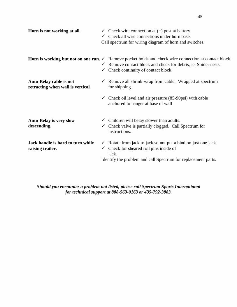
Trouble Shooting Guide
Always check the obvious things first. Some times it’s a simple fix to solve a problem. With wire connections you may have to recrimp the fitting. Please call if your problem is not listed or unable to remedy problem.
SYMPTOMS REMEDIES Light(s) not working � Check for burned out bulb(s), bulb might be loose in socket.
� Refer to Owners manual for wiring diagram of trailer and
plug. � Make sure trailer and towing vehicle plugs are compatible. Call Spectrum for complete trailer wiring diagram. Brake(s) problem
Refer to Dexter Axle Operation Maintenance Manual for specific remedies.
� Charge battery or use jumper cables to raise wall. Hydraulic Power unit not working.
� Check remote control connection to trailer. � Check continuity of motor solenoid. Call Spectrum for details.
� Remove tie-down strap from front of wall.
Hydraulic Power unit motor is working but wall will not raise.
� Check oil level in power unit reservoir tank � Check wire connection(s) to valve solenoid(s).
� If flow control(s) are closed, possible bad flow control(s). Call
Spectrum for instructions. � Check wiring from remote socket to power unit. � Check remote wiring, if loose, call Spectrum for diagram.
� Check wire connection(s) to valve solenoid(s). Hydraulic Power unit motor is working but wall will not lower. � If flow control(s) are closed, possible bad flow control. Call
Spectrum for instructions.
� Sticking valve spool. Call spectrum for
instructions.
� Check wiring from remote socket to power unit. Call Spectrum for
diagram.
� Check Pendant wiring. Loose wire. Call Spectrum for
diagram.
45
� Check wire connection at (+) post at battery. Horn is not working at all. � Check all wire connections under horn base. Call spectrum for wiring diagram of horn and switches.
� Remove pocket holds and check wire connection at contact block.
Horn is working but not on one run. � Remove contact block and check for debris, ie. Spider nests. � Check continuity of contact block.
� Remove all shrink-wrap from cable. Wrapped at spectrum for shipping
Auto-Belay cable is not retracting when wall is vertical.
� Check oil level and air pressure (85-90psi) with cable
anchored to hanger at base of wall
� Children will belay slower than adults. Auto-Belay is very slow descending. � Check valve is partially clogged. Call Spectrum for
instructions. Jack handle is hard to turn while � Rotate from jack to jack so not put a bind on just one jack. raising trailer.
� Check for sheared roll pins inside of
jack. Identify the problem and call Spectrum for replacement parts.
Should you encounter a problem not listed, please call Spectrum Sports International
for technical support at 888-563-0163 or 435-792-3883.

46
Appendix E
The following form is the ClimbNdangle/DropARock Order form for replacement or accessory needs. Please refer to the attached parts list if ordering a replacement item or with warranty questions.

47
BILL TO:Date: __________ Contact:___________________________ Company:____________________________________________Company:_________________________________________ Address:__________________________________________________
Address: ______________________________________________ _________________________________________________________
______________________________________________________ Attn:____________________________ Phone:___________________
CND _______ DAR ________ 24' ________ 32' __________Order Taken By: ___________________________________Date Order Shipped: ________________________________ Year Manufactured: ________Comments:
Quantity Unit Price Tota l
60$ 60$ 54$
Jack w/ Bolt on Plate 150$ Rear Jack Sliding Attachment 80$ FrontJack Attachment 30$
70$ Buzzer contacts 29$ Cylinder (Specify date manuf.) 225$ Cylinder Seal Kit 45$ Regular Handholds & Hardware (Each) (Specify size and color) 7$
80$ 19$
Quick Link 5$ 300$
Remote to Hydraulic Lift (non folding-2 button) 200$ Replacement Pulleys (6 inch) 19$ Certified Cable with BOTH ends crimped for 24' wall (Specify length) 120$ Certified Cable with BOTH ends crimped for 32' wall (Specify length) 150$
25$ 25$
Operator / Owners Manual (for DAR, CND or Auto-Belay's) 25$ 390$
Trailer Jack Handle Repair Kit 15$ Trailer Jack Gear Kit 16$ W all Management System (Counts number of climbs) 1,200$
Tota l Merchandise: Spectrum Sports, Inc
Shipping & Handling:
Call for specia l arrangements for international ord ers. *C.O.D. (Additiona l Charge - $8.00) $____________________
Sales Tax (on subtota l)(Utah res idents only - 6.35%)
Adult Harness Size #1 (XS-L)Description
Shipping: UPS ___ Fed Ex ___ Via: Ground _____ 3-day _____ 2-day ____ Overnight _____ Other ___________
Payment Type: C.O.D. ______ CC ______ Card #:_____________________________________ Exp Date:_______________ Name on Credit Card: ______________________________ Address on Card: ________________________________________
Swivels
Adult Harness Size #2 (M-XL)
Remote to Hydraulic Lift (folding-4 button)
Buzzer (Complete unit, includes pocket)
Child Harness
All other replacement parts available. Call for prices.
Carabineers-auto locking
W arning Sign (Each)
"Closed Sign" - Prevention Cover / DAR or CND
Rules Sign (Each)
$_____________________Please make check or money order payable to:
$_____________________
*Effective 8/1/03 $_____________________
87 East 200 North P.O. Box 58, Hyrum, Utah 84319 Spectrum Sports, Inc Accesso ries & Parts
Staionary ________ Mobile ________ Serial # _____________
PRODUCT INFORMAT ION:Phone:_____________________Fax: __________________
Te l: (888)563-0163 (435)245-3128 Fax: (435)245-0454 http://www .spectrums ports.com
SHIP T O: (If different than Bill To address, please indicate!)
Check box if you are the original owner of wall.

48
Wiring Diagram for Bargman 7 and 9 Circuit, 12V Electrical Connectors
Double Filament Stop & Left-hand Signal Bulb To Terminal #5 #1 Terminal to White Common Ground Auxiliary Ground Or Extra Auxiliary Circuit #5 Terminal to To Terminal #7 Red Stop and Left turn Electric Brake To Terminal #2 #4 Terminal to Black Battery Charge
Tail/Running #7 Auxiliary Ground
& License light Yellow or Backup light
To Terminal #3
#3 Terminal to Tail Green Running, License Light Battery Charge To Terminal #4 #6 Terminal to Stop & Common Ground Brown Right turn To Terminal #1 #2 Terminal to Electric Blue Brake Double Filament Bulb Stop & Right-hand Signal To Terminal # 6
#57 Conctr.
Green
Brown
Black
Blue
Green
Red
White
Yellow
Trailer Side
49
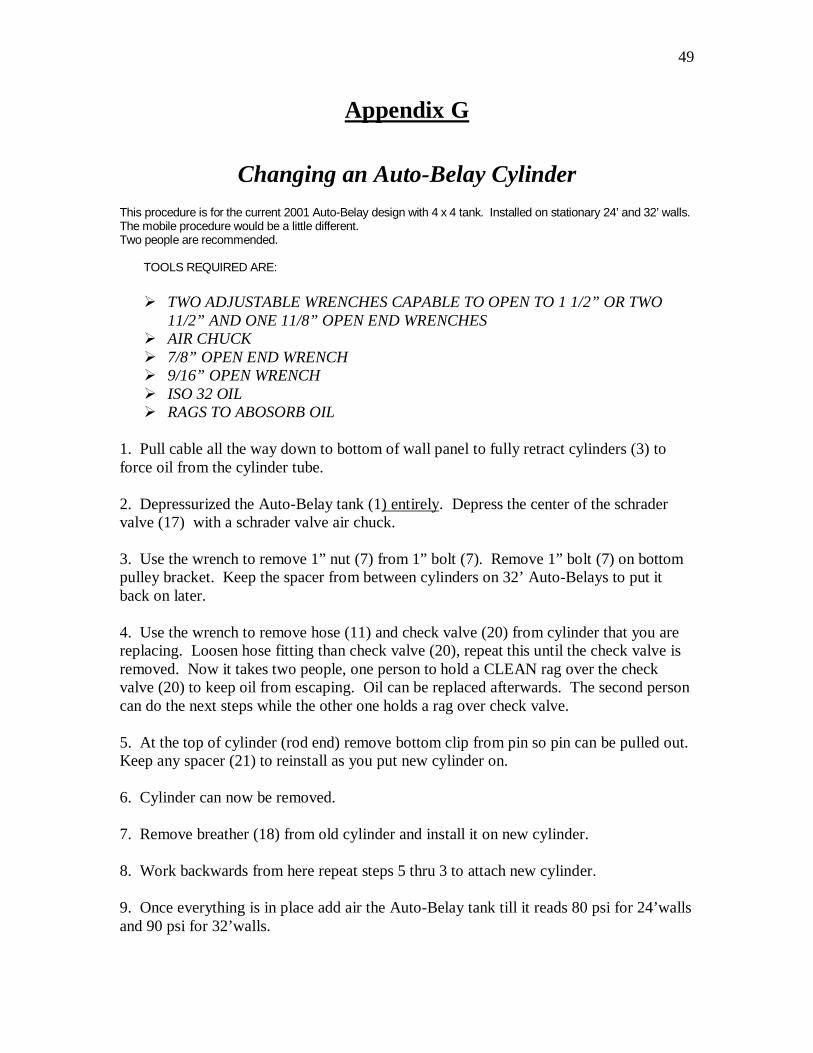
Appendix G
Changing an Auto-Belay Cylinder This procedure is for the current 2001 Auto-Belay design with 4 x 4 tank. Installed on stationary 24’ and 32’ walls. The mobile procedure would be a little different. Two people are recommended.
TOOLS REQUIRED ARE:
� TWO ADJUSTABLE WRENCHES CAPABLE TO OPEN TO 1 1/2” OR TWO 11/2” AND ONE 11/8” OPEN END WRENCHES
� AIR CHUCK � 7/8” OPEN END WRENCH � 9/16” OPEN WRENCH � ISO 32 OIL � RAGS TO ABOSORB OIL
1. Pull cable all the way down to bottom of wall panel to fully retract cylinders (3) to force oil from the cylinder tube. 2. Depressurized the Auto-Belay tank (1) entirely. Depress the center of the schrader valve (17) with a schrader valve air chuck. 3. Use the wrench to remove 1” nut (7) from 1” bolt (7). Remove 1” bolt (7) on bottom pulley bracket. Keep the spacer from between cylinders on 32’ Auto-Belays to put it back on later. 4. Use the wrench to remove hose (11) and check valve (20) from cylinder that you are replacing. Loosen hose fitting than check valve (20), repeat this until the check valve is removed. Now it takes two people, one person to hold a CLEAN rag over the check valve (20) to keep oil from escaping. Oil can be replaced afterwards. The second person can do the next steps while the other one holds a rag over check valve. 5. At the top of cylinder (rod end) remove bottom clip from pin so pin can be pulled out. Keep any spacer (21) to reinstall as you put new cylinder on. 6. Cylinder can now be removed. 7. Remove breather (18) from old cylinder and install it on new cylinder. 8. Work backwards from here repeat steps 5 thru 3 to attach new cylinder. 9. Once everything is in place add air the Auto-Belay tank till it reads 80 psi for 24’walls and 90 psi for 32’walls.
50
10. Purge the air out of cylinders by repeatedly pulling cable down and allow rising by hand until resistance is felt through out the entire down stoke. Now check oil level. 11. If oil has to be added to make oil level in middle of sight gage, repeat step 2. Remove fill plug at top of tank with a 7/8” wrench or a 5/16” Allen wrench. Add oil than tighten fill plug and repeat step 9. Check oil level again. Repeat if necessary to acquire oil level to be in the middle of sight gage.

51
+/-.030.X PROJECT
GENERALASSEMBLY
SEE DWG 22AB002 FORCARRIAGE AND CABLEASSEMBLY DIAGRAMS
12 EXPLODED FINAL ASSEMBLY24/32 AUTO BELAY
GENERAL ARRANGEMENT (5x4)
CLIMBING WALL AUTO BELAYS
SHT.
DO NOT SCALE
MACHINE FINISH
ANGLES +/- 1/2 DEG.
CAD FILE
.XXXX
.XXX
.XX
125 FLARE V & BEVEL FILL FLUSHSQUARE GROOVE = SEAL WELD
SCALE
FILLET WELDS 3/16"
2. PAINT (COLOR)
1. HOLES XXXXXØ UNO.
3. ALL WELDS UNO
+/-.0005
+/-.010
+/-.005
DRAWING NUMBER
TITLE
OF
REV
CARRIAGE PULLEY ASSEMBLIESIN LEFT & RIGHT GROUPINGSOF THE PULLEYS, SET TO ALIGNWITH DAVITS IN WALL ASSEMBLY
PRESSURE STICKER
11
TO ITEM 12
BATCH NUMBER10
STICKER
8
7
9
18
TO ITEM 11BELAY
8
9
713
14
1020
3
15
16
5
64
6
16
19
PINS & CLIPSw/CYLINDER
21
87 E. 200 N. HYRUM UTAH tel:(435)245-3128
ACTION AMUSEMENTS, INC.
HYDRAULIC FLUIDFILL RESERVOIR TUBE WITHISO 32 HYDRAULIC FLUIDUP TO MID LEVEL OF SIGHTTUBE WITH BELAY SET UPIN VERTICAL POSITION:APPROX. 7 QUARTS.
AIR PRESSURE
SEALANT MUST BE USED AT THE
DIMENSIONS IN INCHES
FRACTIONS: +/- 1/16
TOLERANCES
SPECIFIEDUNLESS OTHERWISE
FOLLOWING FITTINGS:
15
12
DECIMALS:
REV BY
11
DRAWN DATE
APPROVED
CHECKED
DATE
DATE
CLIENT
DESCRIPTION
17
AT FILTER END OF TEE
NOTE: LOCKTITE HYDRAULIC FITTING THREAD 18
17
DATE
80-90 PSI
1
2
ITEM
BILL OF MATERIAL
DESCRIPTIONQTY REMARKS
52
Appendix H
Cable Replacement Instructions (Both Ends Terminated)
This procedure will work for mobile and stationary walls equipped with the 2001 model Auto-Belay. Spectrum Sports International cannot be held liable for injuries sustained from changing out cable(s). The customer will have to use their better judgment and have the ability to perform this task safely. TOOLS REQUIRED ARE: � Two people are recommended � Two 15/16 open-end wrenches or two adjustable wrenches � Two 7/16 open-end wrenches � Air chuck � One 5/8 open-end wrench � Replacement Cable � 6’ ladder if changing one of the middle routes � 30-40 minutes per cable change out
1. To change cable(s) on a mobile wall, have the wall lying down onto trailer. For
stationary walls, the procedure is the same except the work has to be performed off the ground. You will have to let all of the air pressure out of the Auto-Belay tank. To depressurize the Auto-Belay(s), attach an air chuck onto schrader valve (#17). Pull the cable with the red hose towards the bottom of the climbing wall so the cylinders are compressed completely. This will put the pulley cart (#1) closer to the bottom pulleys.
2. Make note of which side the cable enters the Auto-Belay pulley cart and the side it
terminates to and how the cable is routed from pulley to pulley. Use a piece of tape to mark each side of the pulley cart. Refer closely to assembly diagram.
3. Use the 5/8 open-end wrenches to open the quick link (#15) so the cable end can be
removed. The quick link can remain attached to the pulley cart (#1). 4. If the cable end does not fit between the pulleys and the top of the Auto-Belay tank,
the pulley assemblies have to be disassembled. Start by removing the ¼” nuts from the ¼” bolts (#7) with the 7/16 wrench from the pulley cart and the bottom pulley assembly. Keep hardware and spacers (#6) together.

53
5. Now remove the 5/8” nut from the 5/8” bolt (#8) using 15/16 wrenches or adjustable wrenches, from pulley cart and bottom pulley assembly. Take care not to lose the spacer (#5) and spacers (#4 and #3), while removing all pulleys.
6. Now use the 15/16 wrenches to loosen the 5/8” nut from the 5/8” bolt of the bottom
pulley on the davit at the top of the wall, enough to remove cable. The upper pulley on the davit will need to be removed entirely to remove cable. A stepladder may be required if you are replacing a cable on a middle route. Once the top pulley is removed, you can then remove the old cable entirely.
7. When replacing the cable, take extreme care not to kink or pinch cable by pulling on
it when there is a loop in the cable. 8. Lay the new cable out on the ground first, to remove loops and have the red hose at
the bottom of the wall. 9. Start feeding the end of the cable through the top pulley mount on the davit and then
place pulleys grove on cable and finish remounting the pulley. Do the same to the second pulley on the davit. Tighten the 5/8” nuts to 5/8” bolts.
10. Now pull enough cable to reach pulley cart. Make sure the cable doesn’t go
underneath or behind a steel wall support while doing this. 11. This is where two people are required. Have cable enter the pulley cart, the side that
is marked with tape. Pull cable to bottom pulley area, place cable on pulley and start 5/8” bolt thru the side plate. Place the correct spacer (#4) on the 5/8” bolt; put pulley with cable on the bolt. Pull cable towards the pulley cart. Start the 5/8” bolt, place spacer (#5) on bolt, place cable on pulley, place pulley on bolt. Repeat these steps using the correct spacers until cable ends at the quick link. Place and tighten 5/8” nuts onto 5/8” bolts. Replace all ¼” bolts (#7) and ¼” nuts and spacers (#6), to keep cable on pulleys. Refer closely to assembly diagram.
12. Make sure you attach terminated cable end onto quick link and tighten quick link with
wrench. 13. Reattach carabineer, swivel and quick link to cable with the red hose that is on the
outside of the climbing wall. Attach carabineer to wall. 14. You now can repressurize the Auto-Belay to the recommended air pressure. Add air
slowly to the Auto-Belay tank so that the cylinders don’t rapidly extend and cause the cable to jam in a pulley.

54
13
5
BOTTOM CABLE TO SECOND PULLEY
BOTTOM CABLE TO THIRD PULLEY
BOTTOM CABLE T
O FOURTH PULLEY
TOP CABLE TO
FIRST PU
LLEY
TOP CA
BLE TO SECOND PULLEY
TOP CABLE TO THIRD PULLE
Y
TOP CABLE THROUGH TOP
OF CARRIAGE UP TO DAVITS
PULLEY
DEAD END BOTTO
M CABLE
TO FIRST PU
LLEY
4 2
23
3
6
7
8
1
11
10
9
11
10
9
1210
9
910
12
BOLTED-ON BEARINGARRANGEMENT WITHITEMS 9 , 10 , 11 & 12IS TYPICAL NEAR SIDEAND FAR SIDE OFCARRIAGE FRAME.
13
NOTE:THESE PULLEYS ARE LOCATED IN THE STATIONARY BRACKETSWHICH ARE PART OF THE BELAY RESERVOIR TUBE ASSEMBLYSHOWN ON DWG 22AB001. CABLE IS INSTALLED AFTER THECARRIAGE ASSEMBLY SHOWN AT RIGHT HAS BEEN ATTACHED TOTHE HYDRAULIC CYLINDERS ON THE BELAY RESERVOIR TUBE.
CABLE THREADINGDIAGRAM
ASSEMBLY DIAGRAMBELAY PULLEY CARRIAGE
CABLE SHOWN FOR THREADING PURPOSES ONLYDO NOT INSTALL UNTIL AFTER THIS CARRIAGEIS MOUNTED ON THE BELAY RESERVOIR TUBE.
NOTE:RIGHT HAND PULLEYARRANGEMENT SHOWN.LEFT HAND ARRGMTHAS SPACERS ATOPPOSITE SIDES.
THREADING SHOWN FOR RIGHT HAND CARRIAGE.LEFT HAND CARRIAGE STARTS FROM OPPOSITESIDE OF CARRIAGE.
BOTTOM CABLE TO FIFT
H PULLEY
TOP CABLE TO FOURTH PU
LLEY
2 3
7
BILL OF MATERIAL
DESCRIPTIONQTYITEM REMARKS
87 E. 200 N. HYRUM UTAH tel:(435)245-3128
PROJECT
BYREV
DECIMALS:FRACTIONS: +/- 1/16 CLIENT
DIMENSIONS IN INCHES
TOLERANCES
SPECIFIEDUNLESS OTHERWISE
DATE
DATE
DATE
APPROVED
CHECKED
DRAWN
CAD FILE
DO NOT SCALE
125MACHINE FINISH
ANGLES +/- 1/2 DEG.
+/-.010
+/-.005+/-.0005
.XXX.XXXX
.XX
SQUARE GROOVE = SEAL WELD
FLARE V & BEVEL FILL FLUSHFILLET WELDS 3/16"
2. PAINT (COLOR)
1. HOLES XXXXXØ UNO.
3. ALL WELDS UNO
TITLE
SCALE
+/-.030.X
CARRIAGE EXPLODED ASSEMBLY24/32 AUTO BELAY
GENERAL ARRANGEMENT (5x4)
CLIMBING WALL AUTO BELAYS
ACTION AMUSEMENTS, INC.
DATEDESCRIPTION
OFSHT.
REVDRAWING NUMBER
TYP 3 PL

55

56