moats and drawbridges: an isolation primitive for recon gurable
TRANSCRIPT

Moats and Drawbridges: An Isolation Primitivefor Reconfigurable Hardware Based Systems
Ted Huffmire�, Brett Brotherton†, Gang Wang†, Timothy Sherwood�,Ryan Kastner†, Timothy Levin‡, Thuy Nguyen‡, and Cynthia Irvine‡
� University of California, Santa BarbaraDepartment of Computer Science
Santa Barbara, CA 93106{huffmire,sherwood}@cs.ucsb.edu
† University of California, Santa BarbaraDepartment of Electrical and Computer Engineering
Santa Barbara, CA 93106{bbrother,wanggang,kastner}@ece.ucsb.edu
‡ Naval Postgraduate SchoolDepartment of Computer Science
Monterey, CA 93943{levin,tdnguyen,irvine}@nps.edu
Abstract
Blurring the line between software and hardware, re-configurable devices strike a balance between the raw highspeed of custom silicon and the post-fabrication flexibilityof general-purpose processors. While this flexibility is aboon for embedded system developers, who can now rapidlyprototype and deploy solutions with performance approach-ing custom designs, this results in a system developmentmethodology where functionality is stitched together froma variety of “soft IP cores,” often provided by multiple ven-dors with different levels of trust. Unlike traditional soft-ware where resources are managed by an operating system,soft IP cores necessarily have very fine grain control overthe underlying hardware. To address this problem, the em-bedded systems community requires novel security primi-tives which address the realities of modern reconfigurablehardware. We propose an isolation primitive, moats anddrawbridges, that are built around four design properties:logical isolation, interconnect traceability, secure reconfig-urable broadcast, and configuration scrubbing. Each ofthese is a fundamental operation with easily understood for-mal properties, yet maps cleanly and efficiently to a wide va-riety of reconfigurable devices. We carefully quantify the re-quired overheads on real FPGAs and demonstrate the utilityof our methods by applying them to the practical problem ofmemory protection.
1 Introduction
Reconfigurable hardware, such as a Field ProgrammableGate Array (FPGA), provides a programmable substrateonto which descriptions of circuits can be loaded and exe-cuted at very high speeds. Because they are able to providea useful balance between performance, cost, and flexibil-ity, many critical embedded systems make use of FPGAsas their primary source of computation. For example, theaerospace industry relies on FPGAs to control everythingfrom satellites to the Mars Rover. Their circuit-level flexi-bility allows system functionality to be updated arbitrarilyand remotely. Real-time and military projects, such as theJoint Strike Fighter, make frequent use of FPGAs becausethey provide both high-performance and well-defined tim-ing behavior, but they do not require the costly fabricationof custom chips.FPGA technology is now the leading design driver for
almost every single foundry1 meaning that they enjoy thebenefits of production on a massive scale (reduced cost, bet-ter yield, difficult to tamper with), yet developers are freeto deploy their own custom circuit designs by configuringthe device in the appropriate ways. This has significantlylowered the primary impediment to hardware development,cost, and as such we are now seeing an explosion of recon-figurable hardware based designs in everything from face
1A foundry is a wafer production and processing plant available on acontract basis to companies that do not have wafer fab capability of theirown

recognition systems [39], to wireless networks [42], to in-trusion detection systems [20], to supercomputers [5]. Infact it is estimated that in 2005 alone there were over 80,000different commercial FPGA designs projects started. [36]Unfortunately, while the economics of the semiconductorindustry has helped to drive the widespread adoption of re-configurable devices in a variety of critical systems, it isnot yet clear that such devices, and the design flows used toconfigure them, are actually trustworthy.
Reconfigurable systems are typically cobbled togetherfrom a collection of exiting modules (called cores) in orderto save both time and money. Although ideally each of thesecores would be formally specified, tested, and verified by ahighly trusted party, in reality, such a development modelcannot hope to keep up with the exponential increases in cir-cuit area and performance made possible by Moore’s Law.Unlike uni-processor software development, where the pro-gramming model remains fixed as transistor densities in-crease, FPGA developers must explicitly take advantage ofdenser devices through changes in their design. Given thatembedded design is driven in large part by the demand fornew features and the desire to exploit technological scalingtrends, there is a constant pressure to mix everything on asingle chip: from the most critical functionality to the latestfad. Each of these cores runs “naked” on the reconfigurabledevice (i.e., without the benefit of an operating system orother intermediate layer), and it is possible that this mixingof trust levels could be silently exploited by an adversarywith access to any point in the design flow (including de-sign tools or implemented cores). In an unrestricted designflow, even answering the question of “are these two corescapable of communication” is computationally difficult toanswer.
Consider a more concrete example, a system with twosoft-processor cores and an AES encryption engine shar-ing a single FPGA. Each of these three cores requires ac-cess to off-chip memory to store and retrieve data. Howcan we ensure that the encryption key for one of the pro-cessors cannot be obtained by the other processor by eitherreading the key from external memory or directly from theencryption core itself? There is no virtual memory on thesesystems, and after being run through an optimizing CADtool the resulting circuit is a single entangled mess of gatesand wires. To prevent the key from being read directly fromthe encryption core itself, we must find some way to iso-late the encryption engine from the other cores at the gatelevel. To protect the key in external memory, we need toimplement a memory protection module, we need to en-sure that each and every memory access goes through thismonitor, and we need to ensure that all cores are commu-nicating only through their specified interfaces. To ensurethese properties hold at even the lowest levels of implemen-tation (after all the design tools have finished their transfor-
mations), we argue that slight modifications in the designmethods and tools can enable the rapid static verificationof finished FPGA bitstreams2. The techniques presented inthis paper are steps towards a cohesive reconfigurable sys-tem design methodology that explicitly supports cores withvarying levels of trust and criticality – all sharing a singlephysical device.Specifically, we present the idea of Moats and Draw-
bridges, a statically verifiable method to provide isolationand physical interface compliance for multiple cores on asingle reconfigurable chip. The key idea of the Moat is toprovide logical and physical isolation by separating coresinto different areas of the chip with “dead” channels be-tween them that can be easily verified. Note that this doesnot require a specialized physical device; rather, this workonly assumes the use of commercially available commodityparts. Given that we need to interconnect our cores at theproper interfaces (Drawbridges), we introduce interconnecttracing as a method for verifying that interfaces carryingsensitive data have not been tapped or routed improperly toother cores or I/O pads. Furthermore, we present a tech-nique, configuration scrubbing, for ensuring that remnantsof a prior core do not linger following a partial reconfigura-tion of the system to enable object reuse. Once we have aset of drawbridges, we need to enable legal inter-core com-munication. We describe two secure reconfigurable com-munication architectures that can be easily mapped into theunused moat areas (and statically checked for isolation), andwe quantify the implementation trade-offs between themin terms of complexity of analysis and performance. Fi-nally, to demonstrate the efficacy of our techniques, we ap-ply them to a memory protection scheme that enforces thelegal sharing of off-chip memory between multiple cores.
2 Reconfigurable Systems
As mentioned in Section 1, a reconfigurable system istypically constructed piecemeal from a set of existing mod-ules (called cores) in order to save both time and money;rarely does one design a full system from scratch. Oneprime example of a module that is used in a variety of con-texts is a soft-processor. A soft-processor is simply a con-figuration of logical gates that implements the functionalityof a processor using the reconfigurable logic of an FPGA.A soft-processor, and other intellectual property (IP) cores3
such as AES implementations and Ethernet controllers, can
2bitstreams are the term for the detailed configuration files that encodethe exact implementation of a circuit on reconfigurable hardware – in manyways they are analogous to a statically linked executable on a traditionalmicroprocessor
3Since designing reconfigurable modules is costly, companies havedeveloped several schemes to protect this valuable intellectual property,which we discuss in Section 6.
be assembled together to implement the desired function-ality. Cores may come from design reuse, but more oftenthan not they are purchased from third party vendors, gen-erated automatically as the output of some design tool, oreven gathered from open source repositories. While indi-vidual cores such as encryption engines may be formallyverified [30], a malicious piece of logic or compromiseddesign tool may be able to exploit low level implementa-tion details to quietly eavesdrop on, or interfere with, trustedlogic. As a modern design may implement millions of logi-cal gates with tens of millions of interconnections, the goalof this paper is to explore design techniques that will allowthe inclusion of both trusted and untrusted cores on a singlechip, without the requirement that expensive static verifica-tion be employed over the entire finished design. Such ver-ification of a large and complex design requires reverse en-gineering, which is highly impractical because many com-panies keep details about their bit-streams proprietary.Increasingly we are seeing reconfigurable devices
emerge as the flexible and high-performance workhorsesinside a variety of high performance embedded computingsystems [4, 9, 11, 22, 35, 45], but to understand the potentialsecurity issues, we need to build on an understanding of atleast a simplified modern FPGA design flow. In this sectionwe describe a modern device, a typical design flow, and thepotential threats that our techniques are expected to handle.
2.1 Reconfigurable Hardware
FPGAs lie along a continuum between general-purposeprocessors and application-specific integrated circuits(ASICs). While general purpose processors can execute anyprogram, this generality comes at the cost of serialized ex-ecution. On the other hand, ASICs can achieve impressiveparallelism, but their function is literally hard wired into thedevice. The power of reconfigurable systems lies in theirability to flexibly customize an implementation down at thelevel of individual bits and logic gates without requiringa custom piece of silicon. This can often result in perfor-mance improvements on the order of 100x as compared to,per unit silicon, a similar microprocessor [7, 10, 50].The growing popularity of reconfigurable logic has
forced practitioners to begin to consider security implica-tions, but as of yet there is no set of best design practices toguide their efforts. Furthermore, the resource constrainednature of embedded systems is perceived to be a challengeto providing a high level of security [26]. In this paperwe describe a set of low level methods that a) allow effec-tive reasoning about high level system properties, b) can besupported with minimal changes to existing tool flows, c)can be statically verified with little effort, d) incur relativelysmall area and performance overheads, and e) can be usedwith commercial off-the-shelf parts. The advantage of de-
veloping security primitives for FPGAs is that we can im-mediately incorporate our primitives into the reconfigurabledesign flow today, and we are not dependent on the often re-luctant industry to modify the design of their silicon.
2.2 Mixed-Trust Design Flows
Figure 1 shows a few of the many different design flowsused to compose a single modern embedded system. Thereconfigurable implementation relies on a large number ofsophisticated software tools that have been created by manydifferent people and organizations. Soft IP cores, such as anAES core, can be distributed in the form of Hardware De-scription Language (HDL), netlists4 or a bitstream. Thesecores can be designed by hand, or they can be automaticallygenerated by computer programs. For example, the Xil-inx Embedded Development Kit (EDK) [53] software toolgenerates soft microprocessors from C code. Accel DSP[17] translates MATLAB [48] algorithms into HDL, logicsynthesis translates this HDL into a netlist, a synthesis tooluses a place-and-route algorithm to convert this netlist intoa bitstream, with the final result being an implementation ofa specialized signal processing core.Given that all of these different design tools produce a set
of inter-operating cores, you can only trust your final systemas much as you trust your least-trusted design path. If thereis a critical piece of functionality, e.g. a unit that protectsand operates on secret keys, there is no way to verify thatthis core cannot be snooped on or tampered without a set ofisolation strategies.The subversion of design tools could easily result in ma-
licious hardware being loaded onto the device. In fact, ma-jor design tool developers have few or no checks in placeto ensure that attacks on specific functionality are not in-cluded. However, just to be clear, we are not proposinga method that makes possible the use of subverted designtools on a trusted core. Rather, we are proposing a methodby which small trusted cores, developed with trusted tools(perhaps using in-house tools which are not fully optimizedfor performance5) can be safely combined with untrustedcores.
2.3 Motivating Examples
We have already discussed the example of a system withtwo processor cores and an encryption core. The goal of ourmethods is to prevent the encryption key for one of the pro-cessors from being obtained by the other processor by either
4Essentially a list of logical gates and their interconnections5FPGA manufacturers such as Xilinx provide signed cores that can be
trusted by embedded designers, while those freely available cores obtainedfrom sources such as OpenCores are considered to be less trustworthy. Thedevelopment of a trusted tool chain or a trusted core is beyond the scopeof this paper.

FPGA Chip SDRAM (off-chip)
DRAM
DRAM
DRAM
DRAM
DRAM
DRAM
DRAM
DRAM
DRAM
DRAM
DRAM
DRAM
SR
AM
Blo
ck
PPP
BR
AM
BR
AM
BR
AM
BR
AM
BR
AM
BR
AM
BR
AM
BR
AM
PPP
DSPSoft
AESCore
Soft
Core
µSoft
P Core µP Core
Hard
Soft
AlgorithmsMATLAB
gcc ExecutableC Code
HDL
C Code
BitstreamPlaceand
Route
NetlistLogic
Synthesis
EDKµP Core
Accel
DSPBitstream
Placeand
Route
NetlistLogic
Synthesis
HDL
MATLAB
DSP
Application
Figure 1. A Modern FPGA-based Embedded System: Distinct cores with different pedigrees andvaried trust requirements find themselves occupying the same silicon. Reconfigurable logic, hardand soft processor cores, blocks of SRAM, and other soft IP cores all share the FPGA and the sameoff-chip memory. How can we ensure that the encryption key for one of the processors cannot beobtained by the other processor by either reading the key from external memory or directly from theencryption core itself?
reading the key from external memory or directly from theencryption core itself.
Aviation – Both military and commercial sectors relyon commercial off-the-shelf (COTS) reconfigurable com-ponents to save time and money. Consider the exampleof avionics in military aircraft in which sensitive target-ing data is processed on the same device as less sensitivemaintenance data. In such military hardware systems, cer-tain processing components are “cleared” for different lev-els of data. Since airplane designs must minimize weight, itis impractical to have a separate device for every function.Our security primitives can facilitate the design of militaryavionics by providing separation of modules that must beintegrated onto a single device.
Computer Vision – In the commercial world, consider avideo surveillance system that has been designed to protectprivacy. Intelligent video surveillance systems can iden-tify human behavior that is potentially suspicious, and thisbehavior can be brought to the attention of a human op-erator to make a judgment [40] [21]. IBM’s PeopleVisionproject has been developing such a video surveillance sys-tem [46] that protects the privacy of individuals by blurringtheir faces depending on the credentials of the viewer (e.g.,
security guards vs. maintenance technicians). FPGAs area natural choice for any streaming application because theycan provide deep regular pipelines of computation, with noshortage of parallelism. Implementing such a system wouldrequire at least three cores on the FPGA: a video interfacefor decoding the video stream, a redaction mechanism forblurring faces in accordance with a policy, and a networkinterface for sending the redacted video stream to the se-curity guard’s station. Each of these modules would needbuffers of off-chip memory to function, and our methodscould prevent sensitive information from being shared be-tween modules improperly (e.g. directly between the videointerface and the network). While our techniques could notverify the correct operation of the redaction core, they couldensure that only the connections necessary for legal com-munication between cores are made.
Now that we have described a high level picture of theproblem we are attempting to address, we present our twoconcepts, moats and drawbridges, along with the details ofhow each maps to a modern reconfigurable device. In par-ticular, for each approach we specify the threats that it ad-dresses, the details of the technique and its implementation,and the overheads involved in its use. Finally, in Section 5,we show how these low-level protection mechanisms can beused in the implementation of a higher-level memory pro-

tection primitive.
3 Physical Isolation with Moats
As discussed in Section 2, a strong notion of isolationis lacking in current reconfigurable hardware design flows,yet one is needed to be certain that cores are not snoopingon or interfering with each other. Before we can preciselydescribe the problem that moats attempt to solve, we needto begin with a brief description of how routing works (andthe function it serves) in a modern FPGA.On a modern FPGA, the vast majority of the actual sili-
con area is taken up by interconnect (approximately 90%).The purpose of this interconnect is to make it easy to con-nect logical elements together so that any circuit can be re-alized. For example, the output of one NAND gate may berouted to the input of another, or the address wires from asoft-processor may be routed to an I/O pad connected to ex-ternal memory. The routing is completely static: a virtualwire is created from input to output, but that signal may berouted to many different places simultaneously (e.g., oneoutput to many inputs or vice versa).The rest of the FPGA is a collection of programmable
gates (implemented as small lookup-tables called LUTs),flip-flops for timing and registers, and I/O blocks (IOB) fortransferring data into and out of the device. A circuit canbe mapped to an FPGA by loading the LUTs and switch-boxes with a configuration, a method that is analogous tothe way a traditional circuit might be mapped to a set oflogical gates. An FPGA is programmed using a bitstream.This binary data is loaded into the FPGA to execute a partic-ular task. The bitstream contains all the information neededto provide a functional device, such as the configuration in-terface and the internal clock cycle supported by the device.Without an isolation primitive, it is very difficult to pre-
vent a connection between two cores from being estab-lished. Place-and-route software uses performance as anobjective function in its optimization strategy, which canresult in the logical elements and the interconnections oftwo cores to be intertwined. Figure 3 makes the scope ofthe problem more clear. The left hand of Figure 3 showsthe floor plan of an FPGA with two small cores (soft pro-cessors) mapped onto it. The two processors overlap sig-nificantly in several areas of the chip. Ensuring that thetwo never communicate requires that we trace every singlewire to ensure that only the proper connections are made.Such verification of a large and complex design requiresreverse engineering, which is highly impractical becausemany companies keep the necessary details about their bit-streams secret. With moats, fewer proprietary details aboutthe bitstream are needed to accomplish this verification.The difficulty of this problem is made more clear by thezoom-in on the right of Figure 3. The zoom-in shows a
single switch box, the associated LUTs (to the right of theswitch box), and all the wires that cross through that onesmall portion of the chip. A modern FPGA contains on theorder of 20,000 or more such boxes.Isolation is required in order to protect the confidential-
ity and integrity of a core’s data, and helps to prevent inter-ference with a core’s functionality. Our technique allows avery simple static check to verify that, at least at the routinglayer, the cores are sufficiently isolated.
3.1 Building Moats
Moats are a novel method of enhancing the security ofFPGA systems via the physical isolation of cores. Ourapproach involves surrounding each core with a “moat”that blocks wiring connectivity from the outside. The corecan only communicate with the outside world via a “draw-bridge”, which is a precisely defined path to the outsideworld.One straightforward way to accomplish this is to align
the routing tracks used by each of these modules and simplydisable the switches near the moat boundaries. The prob-lem with this simple approach is that, for the purposes ofimproving area and timing efficiency, modern FPGA archi-tectures often support staggered, multiple track segments.For example, the Virtex platform supports track segmentswith lengths 1, 2 and 6, where the length is determinedby measuring the number of Configuration Logic Blocks(CLBs) the segment crosses. For example, a length 6 seg-ment will span 6 CLBs, providing a more direct connec-tion by skipping unnecessary switch boxes along the rout-ing path. Moreover, many platforms such as Virtex support“longline” segments, which span the complete row or col-umn of the CLB array.Figure 4 illustrates our moat architecture. If we allow the
design tool to make use of segment lengths of one and two,the moat size must be at least two segments wide in orderto successfully isolate two cores (otherwise signals couldhop the moats because they would not require a switch boxin the moat). To statically check that a moat is sound, thefollowing properties are sufficient.
1. The target core is completely surrounded by moat ofwidth at least w
2. The target core does not make any use of routing seg-ments longer than length w
In fact, both of these properties are easy to inspect onan FPGA. We can tell if a switch box is part of a moat bysimply checking that it is completely dead (i.e., all the rout-ing transistors are configured to be disconnected). We cancheck the second property by examining all of the long lineswitch boxes to ensure that they are unused. These are easy
FPGA Chip Floor Plan
Soft
µP Core
AESCore
Soft
Soft
µP Core
FPGA Fabric
Switchbox
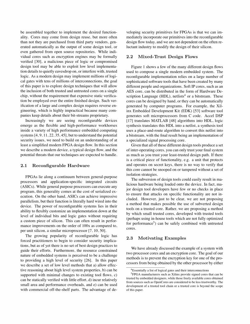
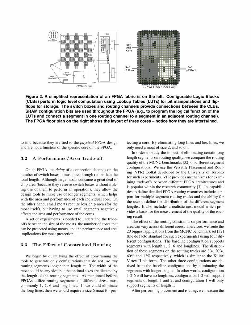
Figure 2. A simplified representation of an FPGA fabric is on the left. Configurable Logic Blocks(CLBs) perform logic level computation using Lookup Tables (LUTs) for bit manipulations and flip-flops for storage. The switch boxes and routing channels provide connections between the CLBs.SRAM configuration bits are used throughout the FPGA (e.g., to program the logical function of theLUTs and connect a segment in one routing channel to a segment in an adjacent routing channel).The FPGA floor plan on the right shows the layout of three cores – notice how they are intertwined.
to find because they are tied to the physical FPGA designand are not a function of the specific core on the FPGA.
3.2 A Performance/Area Trade-off
On an FPGA, the delay of a connection depends on thenumber of switch boxes it must pass through rather than thetotal length. Although large moats consume a great deal ofchip area (because they reserve switch boxes without mak-ing use of them to perform an operation), they allow thedesign tools to make use of longer segments, which helpswith the area and performance of each individual core. Onthe other hand, small moats require less chip area (for themoat itself), but having to use small segments negativelyaffects the area and performance of the cores.A set of experiments is needed to understand the trade-
offs between the size of the moats, the number of cores thatcan be protected using moats, and the performance and areaimplications for moat protection.
3.3 The Effect of Constrained Routing
We begin by quantifying the effect of constraining thetools to generate only configurations that do not use anyrouting segments longer than length w. The width of themoat could be any size, but the optimal sizes are dictated bythe length of the routing segments. As mentioned before,FPGAs utilize routing segments of different sizes, mostcommonly 1, 2, 6 and long lines. If we could eliminatethe long lines, then we would require a size 6 moat for pro-
tecting a core. By eliminating long lines and hex lines, weonly need a moat of size 2, and so on.In order to study the impact of eliminating certain long
length segments on routing quality, we compare the routingquality of the MCNC benchmarks [32] on different segmentconfigurations. We use the Versatile Placement and Rout-ing (VPR) toolkit developed by the University of Torontofor such experiments. VPR provides mechanisms for exam-ining trade-offs between different FPGA architectures andis popular within the research community [3]. Its capabili-ties to define detailed FPGA routing resources include sup-port for multiple segment routing tracks and the ability forthe user to define the distribution of the different segmentlengths. It also includes a realistic cost model which pro-vides a basis for the measurement of the quality of the rout-ing result.The effect of the routing constraints on performance and
area can vary across different cores. Therefore, we route the20 biggest applications from the MCNC benchmark set [32](the de facto standard for such experiments) using four dif-ferent configurations. The baseline configuration supportssegments with length 1, 2, 6 and longlines. The distribu-tion of these segments on the routing tracks are 8%, 20%,60% and 12% respectively, which is similar to the XilinxVirtex II platform. The other three configurations are de-rived from the baseline configurations by eliminating thesegments with longer lengths. In other words, configuration1-2-6 will have no longlines, configuration 1-2 will supportsegments of length 1 and 2, and configuration 1 will onlysupport segments of length 1.After performing placement and routing, we measure the

Core A Core B
small FPGA design with 2 cores
one set of logic blocks and associated routing
Core A and B significantly overlapping
long interconnects switchbox
Figure 3. A simple two-core system mapped onto a small FPGA. The zoom-in to the right showsthe wiring complexity at each and every switch-box on the chip. To statically analyze a large FPGAwith 10s of cores and millions of logical gates, we need to restrict the degrees of freedom. Staticverification of a large, complex design involving intertwined cores requires reverse engineering,which is highly impractical because many companies keep the necessary details about their bit-streams a closely guarded trade secret.
quality of the routing results by collecting the area and thetiming performance based on the critical path of the mappedapplication. To be fair, all the routing tracks are config-ured using the same tri-state buffered switches with Wiltonconnection patterns [52] within the switch box. A Wiltonswitch box provides a good trade-off between routabilityand area, and is commonly used in FPGA routing architec-tures.Figures 5 and 6 show the experimental results, where we
provide the average hardware area cost and critical path per-formance for all the benchmarks over four configurations.The existence of longlines has little impact on the final qual-ity of the mapped circuits. However, significant degradationoccurs when we eliminate segments of length 2 and 6. Thisis caused by the increased demand for switch boxes, result-ing in a larger hardware cost for these additional switch re-sources. Moreover, the signal from one pin to another pin ismore likely to pass more switches, resulting in an increasein the critical path timing. If we eliminate hex and longlines, there is a 14.9% area increase and an 18.9% increasein critical path delay, on average. If the design performanceis limited directly by the cycle time, the delay in criticalpath translates directly into slowdown.
3.4 Overall Area Impact
While the results from Figures 5 and 6 show that thereis some area impact from constraining the routing, there is
10
20
30
40
50
60
70
80
90
100
1 10 100
Eff
ecti
ve U
tilizati
on
(%
)
Number of Cores on Chip
Effective Utilization vs. Number of Cores
Moat Size = 1
Moat Size = 6
Moat Size = 2
Figure 7. The trade-off between the numberof cores, the size of the moat, and the utiliza-tion of the FPGA. An increasing number ofcores results in larger total moat area, whichreduces the overall utilization of the FPGA.Larger moat sizes also will use more area re-sulting in lower utilization.

Switchbox
MoatCore 1 Core 2FPGA Chip Floor Plan
Soft
µP Core
AESCore
Soft
Soft
µP Core
Moat
Figure 4. We use moats to physically isolate cores for security. In this example, segments can eitherspan one or two switch boxes, which requires the moat size to have a length of two. Since thedelay of a connection on an FPGA depends on the number of switch boxes it must pass through,restricting the length of segments reduces performance, but the moats can be smaller. Allowinglonger segments improves performance, but the moats must waste more area.
also a direct area impact in the form of resources requiredto implement the actual moats themselves. Assuming thatwe have a fixed amount of FPGA real estate, we really careabout how much of that area is used up by a combinationof the moats and the core inflation due to restricted routing.We can call this number the effective utilization. Specifi-cally, the effective utilization is:
Ueff =AAllRoutes
ARestrictedRoutes + AMoats
Figure 7 presents the trade-offs between the moat size,the number of isolated cores on the FPGA, and the utiliza-tion of the FPGA. The FPGA used for these calculationswas a Xilinx Virtex-4 Device which has 192 CLB rowsand 116 CLB columns. The figure examines three differ-ent moat sizes: 1, 2 and 6 for a variable number of cores onthe chip (conservatively assuming that a moat is requiredaround all cores). As the number of cores increases, the uti-lization of the FPGA decreases since the area of the moats,which is unusable space, increases. However, when a smallnumber of cores is used, a larger moat size is better becauseit allows us to make more efficient use of the non-moat partsof the chip. If you just need to isolate a single core (from theI/O pads) then a moat of width 6 is the best (consuming 12%of the chip resources). However, as the curve labeled “MoatSize = 2” in Figure 7 shows, a moat width of two has the op-timal effective utilization for designs that have between twoand 120 cores. As a point of reference, it should be notedthat a modern FPGA can hold on the order of 100 strippeddown microprocessor cores. The number of cores is heav-ily dependent on the application, and the trade-off presentedhere is somewhat specific to our particular platform, but ouranalysis method is still applicable to other designs. In fact,as FPGAs continue to grow according to Moore’s Law, the
percent overhead for moats should continue to drop. Be-cause the moats are perimeters, as the size of a core growsby a factor of n, the cost of the moat only grows byO(
√n).
3.5 Effective Scrubbing and Reuse of Re-configurable Hardware
Moats allow us to reason about isolation without anyknowledge of the inner workings of cores, which are far toocomplex to feasibly determine whether a particular elementof a core is connected to another core. Furthermore, moatsalso allow us to isolate cores designed with a less trustwor-thy tool chain from cores that are the result of a more trust-worthy tool chain. While these are both useful properties,we need to make sure we can actually implement them. Infact, a few of the latest FPGAs available have the ability tochange a selective part of their configuration, one column ata time [34]. A specialized core on the FPGA can read oneframe of the configuration, change part of this frame, andwrite the modified frame back. This core must therefore bepart of the trusted computing base of the system.Partial reconfiguration improves the flexibility of a sys-
tem by making it possible to swap cores. If the number ofpossible configurations is small, then static verification issufficient, but if the space of possible cores is infinite, thendynamic verification is necessary. For example, Baker etal. have developed an intrusion detection system based onreconfigurable hardware that dynamically swaps the detec-tion cores [2] [1]. Since the space of intrusion detectionrule sets is infinite, the space of detection cores is also in-finite. Huffmire et al. have developed a memory protec-tion scheme for reconfigurable hardware in which a recon-figurable reference monitor enforces a policy that specifiesthe legal sharing of memory [19]. Partial reconfiguration

Average Area vs. Configuration
0
2
4
6
8
10
12
14
16
18
20
Baseline 1-2-6 1-2 1
Configuration
Min
Wid
th T
ran
sis
tor
Are
as x
10
6
(Moat Size = 1)(Moat Size = 2)(Moat Size = 6)
Figure 5. Comparison of area for differentconfigurations of routing segments. Thebaseline system has segments with length 1,2, 6 and longline. The distribution is closeto that of Virtex II: 8% (1), 20% (2), 60% (6)and 12% (longline). Other configurations arecreated by eliminating one or more classesof segments. For example, configuration 1-2-6 removes the longlines and distributes themproportionally to other types of segments.
Average Timing vs. Configuration
0
2
4
6
8
10
12
14
16
Baseline 1-2-6 1-2 1
Configuration
Av
era
ge
Cri
tic
al
Pa
th T
imin
g (
10
ns
)
(Moat Size = 1)(Moat Size = 2)(Moat Size = 6)
Figure 6. Comparison of critical path timingfor different configurations of routing seg-ments. Unlike Figure 7, the graphs in Figures5 and 6 do not include the overhead of themoat itself. The error bars show one standarddeviation.
could allow the system to change the policy being enforcedby swapping in a different reference monitor. Since thespace of possible policies is infinite, the space of possiblereference monitors is also infinite. Lysaght and Levi havedevised a dynamically reconfigurable crossbar switch [33].By using dynamic reconfiguration, their 928x928 crossbaruses 4,836 CLBs compared to the 53,824 CLBs requiredwithout reconfiguration.
To extend our model of moats to this more dynamic case,we not only need to make sure that our static analysis mustbe simple enough to be performed on-line by a simple em-bedded core (which we argue it is), but we also need to makesure that nothing remains of the prior core’s logic when itis replaced with a different core. In this section, we de-scribe how we can enable object reuse through configura-tion cleansing.
By rewriting a selective portion of the configuration bitsfor a certain core, we can erase any information it has storedin memory or registers. The ICAP (Internal ConfigurationAccess Port) on Xilinx devices allows us to read, modify,and write back the configuration bitstream on Virtex II de-vices. The ICAP can be controlled by a Microblaze softcore processor or an embedded PowerPC processor if thechip has one. The ICAP has an 8-bit data port and typi-cally runs at a clock speed of 50 MHz. Configuration datais read and written one frame at a time. A frame spans theentire height of the device, and frame size varies based on
the device.
Table 1 gives some information on the size and numberof frames across several Xilinx Virtex II devices. The small-est device has 404 frames, and each frame requires 5.04 usto reconfigure, or equivalently, erase. Therefore, reconfig-uring (erasing) the entire devices takes around 2 ms.
To sanitize a core we must perform 3 steps. First we mustread in a configuration frame. The second step is to modifythe configuration frame so that the flip-flops and memoryare erased. The last step is to write back the modified con-figuration frame. The number of frames and how much ofthe frame we must modify depend on the size of the corethat is being sanitized. This process must be repeated sinceeach core will span the width of many frames. In general,the size of the core is linearly related to the time that isneeded to sanitize it.
Our object reuse technique can also disable a core if ex-treme circumstances should require it, such as tampering.Embedded devices such as cell phones are very difficult tosanitize [38]. Smart phones contain valuable personal data,and the theft or loss of a phone can result in serious conse-quences such as identity theft. Embedded devices used bythe military may contain vital secrets that must never fallinto enemy hands. Furthermore, valuable IP information ofthe cores is stored in the form of the bitstream on the FPGA.A method of disabling all or part of the device is needed toprotect important information stored on the FPGA in the

Table 1. Reconfiguration Time
Device # Frames Frame Length (32-bit words) R/W time for 1 frame (ICAP@50 Mhz)XC2V40 404 26 5.04 usXC2V500 928 86 14.64 usXC2C2000 1456 146 24.24 usXC2V8000 2860 286 46.64 us
extreme case of physical tampering.The IBM 4758 is an example of a cryptographic copro-
cessor that has been designed to detect tampering and todisable itself whenever tampering occurs [51]. The device issurrounded by specialized packaging containing wire mesh.Any tampering of the device disturbs this mesh, and the de-vice can respond by disabling itself.
4 Drawbridges: Interconnect Interface Con-formance with Tracing
In the previous section, we described an effective methodfor isolating cores using moats. Our moat methodologyeliminates the possibility for external cores to tap into theinformation contained in a core surrounded by the moat.However, cores do not work in isolation and must commu-nicate with other cores to receive and send data. Therefore,we must allow controlled entry into our core. The entry orcommunication is only allowed with prespecified transac-tions through a “drawbridge”. We must know in advancewhich cores we need to communicate with and the locationof those cores on the FPGA. Often times, it is most effi-cient to communicate with multiple cores through a sharedinterconnection (i.e., a bus). Again, we must ensure thatbus communications are received by only the intended re-cipient(s). Therefore, we require methods to ensure that 1)communication is established only with the specified coresand 2) communication over a shared medium does not re-sult in a covert channel. In this section, we present twotechniques, interconnect tracing and a bus arbiter, to handlethese two requirements.We have developed an interconnect tracing technique for
preventing unintended flows of information on an FPGA.Our method allows a designer to specify the connections ona chip, and a static analysis tool checks that each connec-tion only connects the specified components and does notconnect with anything else. This interconnect tracing tooltakes a bitstream file and a text file that defines the modulesand interconnects in a simple language which we have de-veloped. The big advantage of our tool is that it allows us toperform the tracing on the bitstream file. We do not requirea higher level description of the design of the core. Per-forming this analysis during the last stage of design allows
us to catch illegal connections that could have originatedfrom any stage in the design process including the designtools themselves.In order for the tracing to work we must know the loca-
tions of the modules on the chip and the valid connectionsto/from the modules. To accomplish this we place moatsaround the cores during the design phase. We now know thelocation of the cores and the moats, and we use this infor-mation to specify a text file that defines: all the cores alongwith their location on the chip, all I/O pins used in the de-sign, and a list of valid connections. Then our tool uses theJBits API [13] to analyze the bitstream and check to makesure there are no invalid connections in the design. The pro-cess of interconnect tracing is performed by analyzing thebitstream to determine the status of the switchboxes. Wecan use this technique to trace the path that a connection isrouted along and ensure that it goes where it is supposed to.This tracing technique allows us to ensure that the differentcores can only communicate through the channels we havespecified and that no physical trap doors have been addedanywhere in the design.Ensuring that interconnects between modules are secure
is a necessity to developing a secure architecture. This prob-lem is made more complicated by the abundance of routingresources on an FPGA and the ease with which they can bereconfigured. Our proposed interconnect tracing techniqueallows us to ensure the integrity of connections on a recon-figurable device. This tool gives us the ability to performchecking in the final design stage: right before the bitstreamis loaded onto the device.
4.1 Efficient Communication under theDrawbridge Model
In modern reconfigurable systems, cores communicatewith each other via a shared bus. Unfortunately, the sharednature of a traditional bus architecture raises several secu-rity issues. Malicious cores can obtain secrets by snoopingon the bus. In addition, the bus can be used as a covert chan-nel to leak secret data from one core to another. The easeof reconfigurability on FPGAs allows us to address theseproblems at the hardware level.To address this problem of covert channels and bus
snooping, we have developed a shared memory bus with

Arbiter
BRAM Block
M1 M2 M3 Mn
. . .
Figure 8. Architecture alternative 1. There isa single arbiter and each module has a dedi-cated connection to the arbiter.
Arbiter
BRAM Block
M1 M2 M3 Mn
. . .Arbiter Arbiter Arbiter
TimeMultiplexer
Figure 9. Architecture alternative 2. Eachmodule has its own arbiter that prevents bussnooping and a central time multiplexer thatconnects to all the arbiters.
a time division access. The bus divides the time equallyamong the modules, and each module can read/write oneword to/from the shared memory during its assigned timeslice. Our approach of arbitrating by time division elimi-nates covert channels. With traditional bus arbitration, thereis a possibility of a bus-contention covert channel to exist inany shared bus system where multiple cores or modules ac-cess a shared memory. Via this covert channel, a maliciouscore can modulate its bus references, altering the latency ofbus references for other modules. This enables the transferof information between any two modules that can access thebus [18]. This covert channel could be used to send infor-mation from a module with a high security clearance to amodule with lower security clearance (write-down), whichwould violate a Bell-LaPadula multilevel policy and can-not be prevented through the use of the reference monitor.To eliminate this covert channel, we give each module anequal share of time to use the bus, eliminating the transferof information by modulating bus contention. Since eachmodule can only use the bus during its alloted time slice,it has no way of changing the bus contention. One modulecannot even tell if any of the other modules are using thebus. While this does limit performance of the bus, it re-moves the covert channel. The only other feasible way thatwe see to remove this covert channel is to give each mod-ule a dedicated connection to all other modules. Requiringa dedicated direct connection between each set of modulesthat need to communicate would be inefficient and costly.Dedicated channels would require a worst case of O(2n)connections, where n is the number of modules in the de-sign. Our architecture requires only O(n) connections.
Bus snooping is another major concern associated with ashared bus. Even if we eliminate the covert channels thereis nothing to prevent bus snooping. For example, let us con-sider a system where we want to send data from a classifiedmodule to another and where there are unclassified modules
on the same bus. We need a way to ensure that these lesstrusted modules cannot obtain this information by snoopingthe bus. To solve this problem, we place an arbiter betweenthe module and the memory. The arbiter only allows eachmodule to read during its time share of the bus. In additiona memory monitor is required, but for this work we assumethat such a configuration can be implemented on the FPGAusing the results of Huffmire et. al.[19]
4.2 Architecture Alternatives
We devised two similar architectures to prevent snoop-ing and to eliminate covert channels on the bus. In our firstarchitecture, each module has its own separate connectionto a single arbiter, which sits between the shared memoryand the modules. This arbiter schedules access to the mem-ory equally according to a time division scheduling (Figure8). A module is only allowed to read or write during its al-loted time, and when a module reads, the data is only sent tothe module that issued the read request. The second archi-tecture is more like a traditional bus. In this design, thereis an individual arbiter that sits between each module andthe bus. These arbiters are all connected to a central timingmodule which handles the scheduling (Figure 9). The in-dividual arbiters work in the same way as the single arbiterin the first architecture to prevent snooping and to removecovert channels. To make interfacing easy, both of thesearchitectures have a simple interface so that a module caneasily read/write to the shared memory without having toworry about the timing of the bus arbiter.During the design process, we found that the first archi-
tecture seemed easier to implement, but we anticipated thatthe second architecture would be more efficient. In our firstarchitecture (Figure 8, everything is centralized, making thedesign of a centralized memory monitor and arbiter mucheasier to design and verify. In addition, a single moat could

be used to isolate this functionality. Our second architec-ture (Figure 9) intuitively should be more scalable and effi-cient since it uses a bus instead of individual connections foreach module, but the arbiters have to coordinate, the mem-ory monitor has to be split (if that is even possible), andeach arbiter need to be protected by its own moat.To test our hypotheses, we developed prototypes of both
of the architectures. The prototypes were developed inVHDL and synthesized for a Xilinx Virtex-II device in or-der to determine the area and performance of the designson a typical FPGA. We did not account for the extra moator monitor overhead, but with this assumption results of theanalysis of the two architectures, which can be seen in Ta-ble 2, were not what we first expected. During synthesis ofthe second architecture, the synthesis tool converted the tri-state buffers6 in the bus to digital logic. As a result, the sec-ond architecture used more area than the first and only hada negligible performance advantage. Contrary to what weexpected, the first architecture used roughly 15% less areaon the FPGA and is simpler to implement and verify. Sincethe peformance difference between the two was almost neg-ligible, the first architecture is the better design choice.This bus architecture allows modules to communicate se-
curely with a shared memory and prevents bus snooping andcertain covert channels. When combined with the referencemonitor this secure bus architecture provides a secure andefficient way for modules to communicate.
5 Application: Memory Policy Enforcement
Now that we have described isolation and its relatedprimitives, we provide an example of the application of iso-lation to memory protection, an even higher-level primitive.Saltzer and Schroeder identify three key elements that arenecessary for protection: “Conceptually, then, it is neces-sary to build an impenetrable wall around each distinct ob-ject that warrants separate protection, construct a door inthe wall through which access can be obtained, and post aguard at the door to control its use.” [43]. In addition, theguard must be able to identify the authorized users. In thecase of protecting cores, our moat primitive is analogous tothe wall, and our drawbridge primitive is analogous to thedoor. Our interconnect tracing and secure bus primitives actas the guard.One way of protecting memory in an FPGA system is
to use a reference monitor that is loaded onto the FPGAalong with the other cores [19]. Here, the reference monitoris analogous to the guard because it decides the legality ofevery memory access according to a policy. This requiresthat every access go through the reference monitor. Without
6tri-state buffers are gates that can output either a 0, 1, or Z – a highimpedance state in which the gate acts as if it was disconnected from thewire.
our isolation primitive, it is easy for a core to bypass thereference monitor and access memory directly. Since moatscompletely surround a core except for a small amount oflogic (the drawbridge) for communicating with the rest ofthe chip, it is much easier to prevent a core from bypassingthe reference monitor.Saltzer and Schroeder describe how protection mecha-
nisms can protect their own implementations in addition toprotecting users from each other [43]. Protecting the ref-erence monitor from attack is critical to the security of thesystem, but the fact that the reference monitor itself is re-configurable makes it vulnerable to attack by the other coreson the chip. However, moats can mitigate this problem byproviding physical isolation of the reference monitor.Our isolation primitive also makes it harder for an unau-
thorized information flow from one core to another to oc-cur. Establishing a direct connection between the two coreswould clearly thwart the reference monitor. If moats sur-round each core, it is much harder to connect two cores di-rectly without crossing the moat.As we described above, a reference monitor approach
to memory protection requires that every memory accessgo through the reference monitor. However, cores are con-nected to each other and to main memory by means of ashared bus. As we explained in Section 4.1, the data on ashared bus is visible to all cores. Our secure bus primitiveprotects the data flowing on the bus by controlling the shar-ing of the bus with a fixed time division approach.A memory protection system that allows dynamic pol-
icy changes requires an object reuse primitive. It is oftenuseful for a system to be able to respond to external events.For example, during a fire, all doors in a building shouldbe unlocked without exception (a more permissive policythan normal), and all elevators should be disabled (a lesspermissive policy than normal). In the case of an embeddeddevice, a system under attack may wish to change the policyenforced by its reference monitor. There are several ways tochange polices. One way is to overwrite the reference mon-itor with a completely different one. Our scrubbing prim-itive can ensure that no remnants of the earlier referencemonitor remain. Since cores may retain some informationin their local memory following a policy change, our scrub-bing primitive can also be used to cleanse the cores.
6 Related Work
There has always been an important relationship be-tween the hardware a system runs on and the security of thatsystem. Reconfigurable systems are no different, althoughto the best of our knowledge we are the first to address theproblem of isolation and physical interface conformance onthem. However, in addition to the related work we have al-ready mentioned, we do build on the results of prior related

Table 2. Comparison of Communication Architectures
Architecture 1 Architecture 2 Percent DifferenceSlices 146 169 15.75
Flip Flops 177 206 16.384 Input LUTs 253 305 20.55
Maximum Clock Frequency 270.93 271.297 0.14
efforts. In particular, we build on the ideas of reconfigurablesecurity, IP protection, secure update, covert channels, di-rect channels, and trap doors. While a full description of allprior work in these areas is not possible, we highlight someof the most related.
6.1 Reconfigurable Hardware Security
The closest work to ours is the work of Huffmire et. al.To provide memory protection on an FPGA, Huffmire etal. propose the use of a reconfigurable reference monitorthat enforces the legal sharing of memory among cores [19].A memory access policy is expressed in a specialized lan-guage, and a compiler translates this policy directly to a cir-cuit that enforces the policy. The circuit is then loaded ontothe FPGA along with the cores. While their work addressesthe specifics of how to construct a memory access moni-tor efficiently in reconfigurable hardware, they do not ad-dress the problem of how to protect that monitor from rout-ing interference, nor do they describe how to enforce thatall memory accesses go through this monitor. This paperdirectly supports their work by providing the fundamentalprimitives that are needed to implement memory protectionon a reconfigurable device.There appears to be little other work on the specifics
of managing FPGA resources in a secure manner. Chienand Byun have perhaps the closest work, where they ad-dressed the safety and protection concerns of enhancinga CMOS processor with reconfigurable logic [8]. Theirdesign achieves process isolation by providing a reconfig-urable virtual machine to each process, and their architec-ture uses hardwired TLBs to check all memory accesses.Our work could be used in conjunction with theirs, usingsoft-processor cores on top of commercial off-the-shelf FP-GAs rather than a custom silicon platform. In fact, we be-lieve one of the strong points of our work is that it mayprovide a viable implementation path to those that require acustom secure architecture, for example execute-only mem-ory [31] or virtual secure co-processing [29].Gogniat et al. propose a method of embedded system
design that implements security primitives such as AES en-cryption on an FPGA, which is one component of a secureembedded system containing memory, I/O, CPU, and otherASIC components [12]. Their Security Primitive Controller
(SPC), which is separate from the FPGA, can dynamicallymodify these primitives at runtime in response to the de-tection of abnormal activity (attacks). In this work, the re-configurable nature of the FPGA is used to adapt a cryptocore to situational concerns, although the concentration ison how to use an FPGA to help efficiently thwart systemlevel attacks rather than chip-level concerns. Indeed, FP-GAs are a natural platform for performing many crypto-graphic functions because of the large number of bit-leveloperations that are required in modern block ciphers. How-ever, while there is a great deal of work centered aroundexploiting FPGAs to speed cryptographic or intrusion de-tection primitives, systems researchers are just now start-ing to realize the security ramifications of building systemsaround hardware which is reconfigurable.Most of the work relating to FPGA security has been tar-
geted at the problem of preventing the theft of intellectualproperty and securely uploading bitstreams in the field. Be-cause such attacks directly impact their bottom line, indus-try has already developed several techniques to combat thetheft of FPGA IP, such as encryption [6] [23] [24], finger-printing [27], and watermarking [28]. However, establish-ing a root of trust on a fielded device is challenging becauseit requires a decryption key to be incorporated into the fin-ished product. Some FPGAs can be remotely updated inthe field, and industry has devised secure hardware updatechannels that use authentication mechanisms to prevent asubverted bitstream from being uploaded [16] [15]. Thesetechniques were developed to prevent an attacker from up-loading a malicious design that causes unintended function-ality. Even worse, the malicious design could physicallydestroy the FPGA by causing the device to short-circuit[14]. However, these authentication techniques merely en-sure that a bitstream is authentic. An “authentic” bitstreamcould contain a subverted core that was designed by a thirdparty.
6.2 Covert Channels, Direct Channels,and Trap Doors
The work in Section 4.1 directly draws upon the ex-isting work on covert channels. Exploitation of a covertchannel results in the unintended flow of information be-tween cores. Covert channels work via an internal shared

resource, such as power consumption, processor activity,disk usage, or error conditions [47] [41]. Classical covertchannel analysis involves the articulation of all shared re-sources on chip, identifying the share points, determiningif the shared resource is exploitable, determining the band-width of the covert channel, and determining whether reme-dial action can be taken [25]. Storage channels can be mit-igated by partitioning the resources, while timing channelscan be mitigated with sequential access, a fact we exploit inthe construction of our bus architecture. Examples of reme-dial action include decreasing the bandwidth (e.g., the intro-duction of artificial spikes (noise) in resource usage [44]) orclosing the channel. Unfortunately, an adversary can extracta signal from the noise, given sufficient resources [37].Of course our technique is primarily about restricting the
opportunity for direct channels and trap doors [49]. Ourmemory protection scheme is an example of that. With-out any memory protection, a core can leak secret data bywriting the data directly to memory. Another example of adirect channel is a tap that connects two cores. An uninten-tional tap is a direct channel that can be established throughluck. For example, the place-and-route tool’s optimizationstrategy may interleave the wires of two cores.
7 Conclusion
The design of reconfigurable systems is a complex pro-cess, with multiple software tool chains that may have dif-ferent trust levels. Since it is not cost-effective to develop anoptimized tool chain from scratch to meet assurance needs,only the most sensitive cores should be designed using atrusted tool chain. To meet performance needs, most corescould be designed with commodity tools that are highly op-timized but untrusted, which results in multiple cores on achip with different trust levels. Our methodology will notlead to those less trusted portions becoming more depend-able or correct, but it will isolate trusted portions from theeffects of their subversion or failure. To address this situ-ation, developers will need to build monitored or fail-safesystems on top of FPGAs to prevent the theft of critical se-crets.We have presented two low-level protection mechanisms
to address these challenges, moats and drawbridges, andwe have analyzed the trade-offs of each. Although largermoats consume more area than smaller moats, they havebetter performance because longer segments can be used.Our interconnect tracing primitive works together with ourmoat primitive in a complementary way by allowing smallermoats to be used without sacrificing performance. We havealso described how these basic primitives are useful in theimplementation of a higher-level memory protection prim-itive, which can prevent unintended sharing of informationin embedded systems.
Acknowledgments
The authors would like to thank Virgil Gligor for his in-sightful comments on this paper. We also wish to thank theanonymous reviewers for their helpful feedback. This re-search was funded in part by National Science FoundationGrant CNS-0524771, NSF Career Grant CCF-0448654, andthe SMART Defense Scholarship for Service.
References
[1] Z. Baker and V. Prasanna. Efficient architectures for intrusiondetection. In Twelfth Annual International Conference on Field-Programmable Logic and its Applications (FPL ’04), August 2004.
[2] Z. Baker and V. Prasanna. Computationally-efficient engine for flex-ible intrusion detection. October 2005.
[3] V. Betz, J. S. Rose, and A. Marqardt. Architecture and CAD fordeep-submicron FPGAs. Kluwer Academic, Boston, MA, 1999.
[4] K. Bondalapati and V. Prasanna. Reconfigurable computing systems.In Proceedings of the IEEE, volume 90(7), pages 1201–17, 2002.
[5] U. Bondhugula, A. Devulapalli, J. Fernando, P. Wyckoff, and P. Sa-dayappan. Parallel fpga-based all-pairs shortest-paths in a directedgraph. In Proceedings of the 20th IEEE International Parallel andDistributed Processing Symposium (IPDPS’06), April 2006.
[6] L. Bossuet, G. Gogniat, and W. Burleson. Dynamically configurablesecurity for SRAM FPGA bitstreams. In Proceedings of the 18th In-ternational Parallel and Distributed Processing Symposium (IPDPS’04), Santa Fe, NM, April 2004.
[7] D. Buell and K. Pocek. Custom computing machines: an introduc-tion. In Journal of Supercomputing, volume 9(3), pages 219–29,1995.
[8] A. Chien and J. Byun. Safe and protected execution for themorph/AMRM reconfigurable processor. In Seventh Annual IEEESymposium on Field-Programmable Custom Computing Machines,Napa, CA, April 1999.
[9] K. Compton and S. Hauck. Reconfigurable computing: a survey ofsystems and software. In ACM Computing Surveys, volume 34(2),pages 171–210, USA, 2002. ACM.
[10] A. DeHon. Comparing computing machines. In SPIE-Int. Soc. Opt.Eng. Proceedings of SPIE - the International Society for Optical En-gineering, volume 3526, pages 124–33, 1998.
[11] A. DeHon and J. Wawrzynek. Reconfigurable computing: what,why, and implications for design automation. In Proceedings ofthe Design Automation Conference, pages 610–15, West Point, NY,1999.
[12] G. Gogniat, T. Wolf, and W. Burleson. Reconfigurable security sup-port for embedded systems. In Proceedings of the 39th Hawaii In-ternational Conference on System Sciences, 2006.
[13] S. Guccione, D. Levi, and P. Sundararajan. Jbits: Java-based in-terface for reconfigurable computing. In Proceedings of the SecondAnnual Conference on Military and Aerospace Applications of Pro-grammable Logic Devices and Technologies (MAPLD), Laurel, MD,USA, September 1999.
[14] I. Hadzic, S. Udani, and J. Smith. FPGA viruses. In Proceedings ofthe Ninth International Workshop on Field-Programmable Logic andApplications (FPL ’99), Glasgow, UK, August 1999.
[15] S. Harper and P. Athanas. A security policy based upon hardwareencryption. In Proceedings of the 37th Hawaii International Confer-ence on System Sciences, 2004.

[16] S. Harper, R. Fong, and P. Athanas. A versatile framework for fpgafield updates: An application of partial self-reconfiguration. In Pro-ceedings of the 14th IEEE International Workshop on Rapid SystemPrototyping, June 2003.
[17] T. Hill. Acceldsp synthesis tool floating-point to fixed-point conver-sion of matlab algorithms targeting fpgas, April 2006.
[18] W.-M. Hu. Reducing timing channels with fuzzy time. In IEE Com-puter Society Symposium on Research in Security and Privacy, Oak-land, CA, May 1991.
[19] T. Huffmire, S. Prasad, T. Sherwood, and R. Kastner. Policy-drivenmemory protection for reconfigurable systems. In Proceedings ofthe European Symposium on Research in Computer Security (ES-ORICS), Hamburg, Germany, September 2006.
[20] B. Hutchings, R. Franklin, and D. Carver. Assisting network in-trusion detection with reconfigurable hardware. In Proceedings ofthe 10th Annual IEEE Symposium on Field-Programmable CustomComputing Machines (FCCM’02), 2002.
[21] A. Jain, D. Koppel, K. Kaligian, and Y.-F. Wang. Using stationary-dynamic camera assemblies for wide-area video surveillance and se-lective attention. In IEEE Conference on Computer Vision and Pat-tern Recognition, 2006.
[22] R. Kastner, A. Kaplan, and M. Sarrafzadeh. Synthesis Techniquesand Optimizations for Reconfigurable Systems. Kluwer Academic,Boston, MA, 2004.
[23] T. Kean. Secure configuration of field programmable gate arrays.In Proceedings of the 11th International Conference on Field Pro-grammable Logic and Applications (FPL ’01), Belfast, UK, August2001.
[24] T. Kean. Cryptographic rights management of FPGA intellectualproperty cores. In Tenth ACM International Symposium on Field-Programmable Gate Arrays (FPGA ’02), Monterey, CA, February2002.
[25] R. Kemmerer. Shared resource matrix methodology: An approachto identifying storage and timing channels. In ACM Transactions onComputer Systems, 1983.
[26] P. Kocher, R. Lee, G. McGraw, A. Raghunathan, and S. Ravi. Secu-rity as a new dimension in embedded system design. In Proceedingsof the 41st Design Automation Conference (DAC ’04), San Diego,CA, June 2004.
[27] J. Lach, W. Mangione-Smith, and M. Potkonjak. FPGA fingerprint-ing techniques for protecting intellectual property. In Proceedings ofthe 1999 IEEE Custom Integrated Circuits Conference, San Diego,CA, May 1999.
[28] J. Lach, W. Mangione-Smith, and M. Potkonjak. Robust FPGA in-tellectual property protection through multiple small watermarks. InProceedings of the 36th ACM/IEEE Conference on Design Automa-tion (DAC ’99), New Orleans, LA, June 1999.
[29] R. Lee, P. Kwan, J. McGregor, J. Dwoskin, and Z. Wang. Architec-ture for protecting critical secrets in microprocessors. In Proceed-ings of the 32nd International Symposium on Computer Architecture(ISCA), June 2005.
[30] J. Lewis and B. Martin. Cryptol: High assurance, retargetable cryptodevelopment and validation. In Military Communications Confer-ence (MILCOM), October 2003.
[31] D. Lie, C. Thekkath, M. Mitchell, P. Lincoln, D. Boneh, J. Mitchell,andM. Horowitz. Architectural support for copy and tamper resistantsoftware. In Proceedings of the Ninth International Conference onArchitectural Support for Programming Languages and OperatingSystems (ASPLOS-IX), Cambridge, MA, November 2000.
[32] B. Lisanke. Logic synthesis and optimization benchmarks. Technicalreport, Microelectronics Center of North Carolina, Research TrianglePark, NC, USA, January 1991.
[33] P. Lysaght and D. Levi. Of gates and wires. In Proceedings of the18th International Parallel and Distributed Processing Symposium,2004.
[34] P. Lysaght and J. Stockwood. A simulation tool for dynamically re-configurable field programmable gate arrays. IEEE Transactions onVery Large Scale Integration (VLSI) Systems, 4(3), September 1996.
[35] W. Mangione-Smith, B. Hutchings, D. Andrews, A. DeHon, C. Ebel-ing, R. Hartenstein, O. Mencer, J. Morris, K. Palem, V. Prasanna, andH. Spaanenburg. Seeking solutions in configurable computing. InComputer, volume 30(12), pages 38–43, 1997.
[36] D. McGrath. Gartner dataquest analyst gives asic, fpga markets cleanbill of health. EE Times, June 13 2005.
[37] J. Millen. Covert channel capacity. In Proceedings of the 1987 IEEESymposium on Security and Privacy, 1987.
[38] E. Nakashima. Used cellphones hold trove of secrets that can be hardto erase. Washington Post, October 21 2006.
[39] H. Ngo, R. Gottumukkal, and V. Asari. A flexible and efficient hard-ware architecture for real-time face recognition based on eigenface.In Proceedings of the IEEE Computer Society Annual Symposium onVLSI, 2005.
[40] W. Niu, J. Long, D. Han, and Y.-F. Wang. Human activity detectionand recognition for video surveillance. In Proceedings of the IEEEMultimedia and Expo Conference, Taipei, Taiwan, 2004.
[41] C. Percival. Cache missing for fun and profit. In BSDCan 2005,Ottowa, Ontario, Canada, 2005.
[42] B. Salefski and L. Caglar. Reconfigurable computing in wireless. InProceedings of the Design Automation Conference (DAC), 2001.
[43] J. Saltzer and M. Schroeder. The protection on information in com-puter systems. Communications of the ACM, 17(7), July 1974.
[44] H. Saputra, N. Vijaykrishnan, M. Kandemir, M. Irwin, R. Brooks,S. Kim, and W. Zhang. Masking the energy behavior of des encryp-tion. In IEEE DEsign Automation and Test in Europe (DATE ’03),2003.
[45] P. Schaumont, I. Verbauwhede, K. Keutzer, and M. Sarrafzadeh. Aquick safari through the reconfiguration jungle. In Proceedings ofthe Design Automation Conference, pages 172–7, 2001.
[46] A. Senior, S. Pankanti, A. Hampapur, L. Brown, Y.-L. Tian, andA. Ekin. Blinkering surveillance: Enabling video privacy throughcomputer vision. Technical Report RC22886, IBM, 2003.
[47] F. Standaert, L. Oldenzeel, D. Samyde, and J. Quisquater. Poweranalysis of FPGAs: How practical is the attack? Field-Programmable Logic and Applications, 2778(2003):701–711, Sept.2003.
[48] The Math Works Inc. MATLAB User’s Guide, 2006.
[49] K. Thompson. Reflections on trusting trust. Communications of theACM, 27(8), 1984.
[50] J. Vuillemin, P. Bertin, D. Roncin, M. Shand, H. Touati, and P. Bou-card. Programmable active memories: Reconfigurable systems comeof age. In IEEE Transactions on Very Large Scale Integration (VLSI)Systems, volume 4(1), pages 56–69, 1996.
[51] S. Weingart and S. Smith. Building a high-performance, pro-grammable secure coprocessor. Computer Networks (Special Issueon Computer Network Security), 31:831–860, April 1999.
[52] S. Wilton. Architectures and Algorithms for Field-ProgrammableGate Arrays with Embedded Memory. PhD thesis, University ofToronto, 1997.
[53] Xilinx Inc. Getting Started with the Embedded Development Kit(EDK), 2006.