mme 345 lecture 37 - bangladesh university of engineering...
TRANSCRIPT

MME 345, Lecture 37
Cast Iron Foundry Practices4. Grey iron foundry practices
Ref:
[1] Heine, Loper and Rosenthal. Principles of Metal Casting, Tata McGraw-Hill, 19670
[2] J R Brown (ed.). Foseco Ferrous Foundrymen’s Handbook, Butterworth-Heninemann, 2000
Topics to discuss today …
1. Introduction
2. Moulding practices
3. Gating and feeding
4. Inoculation
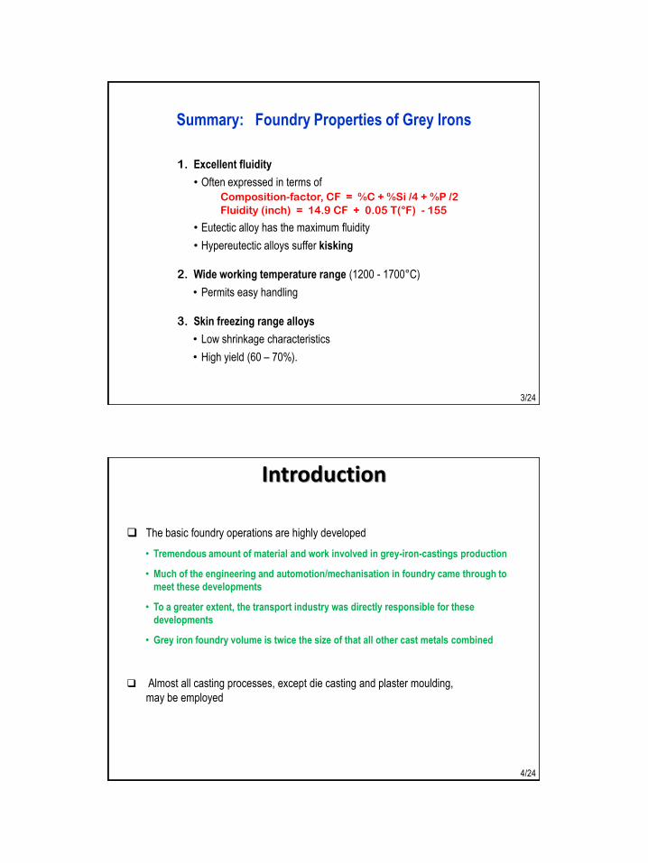
1. Excellent fluidity
• Often expressed in terms of
Composition-factor, CF = %C + %Si /4 + %P /2
Fluidity (inch) = 14.9 CF + 0.05 T(°F) - 155
• Eutectic alloy has the maximum fluidity
• Hypereutectic alloys suffer kisking
2. Wide working temperature range (1200 - 1700°C)
• Permits easy handling
3. Skin freezing range alloys
• Low shrinkage characteristics
• High yield (60 – 70%).
Summary: Foundry Properties of Grey Irons
3/24
The basic foundry operations are highly developed
• Tremendous amount of material and work involved in grey-iron-castings production
• Much of the engineering and automotion/mechanisation in foundry came through to
meet these developments
• To a greater extent, the transport industry was directly responsible for these
developments
• Grey iron foundry volume is twice the size of that all other cast metals combined
Introduction
Almost all casting processes, except die casting and plaster moulding,
may be employed
4/24

Green sand moulding is the most commonly practiced method.
In most cases, grey iron foundries are modernised and mechanised.
Moulding Practices
Some features of moulding aggregates:
• 4-mesh base sand with AFS Fineness number ~60 commonly employed.
• Thermal stability, reusability, mouldability, ease of cleaning, and surface finish is the most
important features in moulding sand mixtures.
• Sand burn-on, sand fuse-on, reaction between sand and metal usually occurred. Sea coal,
coke, graphite, pitch etc. are mixed with sand to prevent or eliminate these defects. Their
effectiveness depends on producing reducing atmosphere in the mould or preventing
oxidising reactions.
• Sea coal (2-8%) is very commonly applied to improve surface finish.
Excessive amount can cause blow defects. Pulverised coke, pitch can also be used.
• Mould coats (graphite) are also applied to improve surface finish.
5/24
Gating and Feeding
Regardless of the most favourable sand conditions and good moulding,
a bad gating practice can ruin the casting.
Certain metallurgical characteristics of grey iron require specialised practices
of gating design.
Fluidity
Important for thin sections with high surface area• misrun is difficult to avoid
• running system and the mould cavity need to be filled as soon as possible
Low fluidity resulted for• low C and Si level, low pouring temperature, hypereutectic alloy
To increase fluidity• increasing temperature rather than changing composition is preferred.
• for an increase of 0.25-0.30% C or 20°F temperature, fluidity increases by 1 in
Reduce transport• pouring of iron must be done with a minimum temperature drop
6/24

Liquid volume shrinkage is about 0.5 % per 100 deg F
• Not problematical; can be compensated by liquid flow
Shrinkage characteristics
Solidification shrinkage
DV, % = 2 (% GC – 2.80 %) GC = graphitic carbon
• White iron (with 0% GC) have about 5.6% shrinkage
• Shrinkage in grey iron can be well compensated by controlling graphitisation
• A normal soft grey iron with composition 3.5% C and 2.2% Si with 0.4-0.6% CC and 2.9-3.1% GC
will virtually expand, rather than shrink
• For ordinary grey iron castings, no feeder is needed to feed solidification shrinkage
• But low C, low Si, less graphitisable castings need feeding
Thus, feeder in grey iron is often need not be used, unless some factors other than
solidification shrinkage requires their use.
• feeder may be needed if mould enlargement occurs at some time after pouring
• solidification under feeder pressure favours sound casting 7/24
Important parameters
• Adequate pouring rate
• Use of slag traps
• Provision of feeding, if required
t = Pouring time, sec
T = Average metal thickness, inch
A = Constant (0.95 for grey iron)
B = Constant (0.835 for grey iron)
W = Weight of casting, lb
t = A + WTB
Gating design
8/24
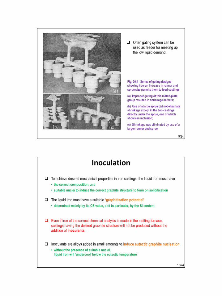
Fig. 20.4 Series of gating designs
showing how an increase in runner and
sprue size permits them to feed castings
(a) Improper gating of this match-plate
group resulted in shrinkage defects;
(b) Use of a large sprue did not eliminate
shrinkage except in the two castings
directly under the sprue, one of which
shows an inclusion;
(c) Shrinkage was eliminated by use of a
larger runner and sprue
Often gating system can be
used as feeder for meeting up
the low liquid demand.
9/24
Inoculation
To achieve desired mechanical properties in iron castings, the liquid iron must have
• the correct composition, and
• suitable nuclei to induce the correct graphite structure to form on solidification
The liquid iron must have a suitable ‘graphitisation potential’
• determined mainly by its CE value, and in particular, by the Si content
Even if iron of the correct chemical analysis is made in the melting furnace,
castings having the desired graphite structure will not be produced without the
addition of inoculants.
Inoculants are alloys added in small amounts to induce eutectic graphite nucleation.
• without the presence of suitable nuclei,
liquid iron will ‘undercool’ below the eutectic temperature
10/24

Inoculation is the process of increasing the numbers of nucleating sites
• from which eutectic graphite can grow during the solidification of flake, nodular
and compacted graphite irons
Main aim of inoculation: minimize undercooling during eutectic solidification
• to make sure that the resultant cast microstructures are completely free from
eutectic carbides
Inoculation also plays a major part in controlling eutectic graphite morphology and
distribution, and hence, the levels of pearlite and ferrite in matrix structures.
In flake graphite (grey) irons, inoculation is used to:
• prevent eutectic carbides, especially in thin sections and at corners
• ensure a uniform distribution of fine type A graphite flakes;
prevent formation of Rosette graphite
• avoid the presence of undercooled graphite and the associated soft free ferrite
in the matrix
11/24
graphite structure of (a) uninoculated grey cast iron (×100) and (b) inoculated grey cast iron (×100)
Uninoculated grey iron castings will contain:
• undercooled forms of graphite (type D/E); associated with this will be ferrite
• cementite in thin sections or close to edges and corners
Such iron is unlikely to meet tensile and hardness specifications and
will be difficult to machine.
12/24

Inoculating materials
Common inoculating materials:
1. graphite base
2. ferrosilicon base
3. calcium silicide base
Graphite itself is a powerful inoculant but it is not effective on low sulphur irons
• these microconstituents are capable of forming microinclusions of complex oxides
or oxysulphides having suitable surface and crystallographic characteristics to
heterogeneously nucleate graphite.
Ferrosilicon (45% or 75% Si) is the most commonly used inoculant.
• pure ferrosilicon is not effective as an inoculant
• it is the presence of around 5% of carefully controlled levels of minor elements
(Ba, Zr, Sr, Bi, Al, Ca, Mn) that determine the effectiveness of the product
13/24
Method of inoculation
There are many methods of inoculations based on time and type of addition.
These are generally classified into two groups:
1. Ladle additionthe inoculant is added either as the liquid iron enters the ladle or just afterwards
2. Late inoculationrefers to treatment after the metal has left the ladle, for example, as it enters the
mould (stream inoculation) or by using an insert in the mould (in-mould inoculation).
Inoculants reach maximum effectiveness immediately after treatment and
fade quickly over a period of 10–20 minutes.
It is therefore desirable to inoculate as late as possible before casting.
14/24

schematic of inoculation methods
INOCULATION
METHODS / TECHNIQUES
Ladle
Inoculation
Gravity
Feeding
Air Assisted
Injection
Injection of
Cored Wire
Late / Post
Inoculation
In-Stream Inoculation
during pouring
into the mould
Wire Injection
during pouring
into the mould
In the Mould
Inoculation
Air Assisted
Injection of Inoculant
Gravity Feeding of
Inoculant
Inoculation in the
Sprue/Runner
Inoculation in the
Pouring Basin
Solid Insert Placed
into the Sprue Well
Crushed Inoculant
Placed into the
Reaction Chamber
Inoculant Placed
onto/into the Filter
Inoculant Block
Placed into the
Pouring Basin
Floating
Inoculant in the
Pouring Basin
15/24
Ladle inoculation
Ladle inoculation should always be added to the metal stream when tapping from
furnace to ladle, or ladle to ladle.
Additions should begin when the ladle is one-quarter full and be completed when the
ladle is three-quarters full, so that the last metal merely mixes.
Never put inoculant into the bottom of the ladle and tap onto it.
The amount of inoculant needed is governed by several factors. The following rules
guide the use of inoculation:
• low carbon equivalent irons require greater amounts of inoculant
• for a given iron, the thinner the section of casting, the greater the inoculation required
• electric melted irons require more inoculation than cupola melted irons
• high steel scrap charges will require more inoculation
• higher treatment necessary if inoculated iron is held for more than a few minutes after inoculation
In general, additions of 0.1–0.5 wt.% of metal will be satisfactory for grey cast irons
Higher additions are needed for ductile (SG) irons
Over-inoculation causes shrinkage porosity problems16/24

ladle inoculation
gravity feeding
air-assisted injection
wire injection
17/24
Late stream inoculation
For foundries with mechanised moulding, melting, and pouring lines,
conventional ladle inoculation is not possible.
Metal stream inoculation is intended for use in these conditions.
It is designed to add controlled amounts of inoculant to the liquid cast iron
just before it enters the mould.
The use of late stream inoculation techniques leads to the virtual elimination of fading.
This causes
• a substantial reduction in the amount of inoculant used
• the inoculant addition thereby produces a smaller change in iron composition leading
to improved metallurgical consistency
• the cost of inoculation is also lower
18/24

Inoculant used in late stream inoculators must have a number of important features:
• It must be a powerful inoculant
• It must be finely divided to ensure free-flowing properties and rapid solution
• It must be very accurately graded, without superfine material which would blow away,
or large particles which jam the gate mechanism.
• It must dissolve rapidly and cleanly to avoid the presence of undissolved inoculant
particles in the castings
Stream inoculation is very efficient since fading is eliminated.
The normal addition rate for grey iron is from 0.03–0.20%, typically 0.1%, much
less than would be used for ladle inoculation.
For ductile iron, addition rates range from 0.06–0.3%, typically 0.2%.
19/24
in stream inoculation
20/24

Mould inoculation
There are several ways in which mould inoculation can be performed:
• powdered inoculant can be placed in the pouring bush; or
• it can be placed at the bottom of the sprue.
A more reliable method is to use sachets or precast slugs of inoculant in the
pouring bush or in the running system
• they gradually dissolve in the metal stream as the casting is poured,
giving uniform dissolution
• this ensures that inoculation takes place just before solidification of the iron
21/24
in the mould inoculation
at the sprue wellin the runner
floating inoculation block
in the pouring basinanchored inoculant block
in the pouring basin
22/24

Control Method
The wedge chill test is a simple and rapid method of assessing the degree of chill
reduction obtained by the use of inoculation in grey cast irons.
•The wedge is made in a mould
prepared from silicate or resin bonded
sand.
•After pouring, it must be allowed to
cool in the mould to a dull red heat
(600°C), after which it can be
quenched in water and fractured.
•The width at the point where clear
chill ceases, t, is measured and this
gives a good indication of the need for
inoculation and of the effectiveness of
an inoculation process.
In general, casting sections should be not less than three times the wedge reading
if chill at the edges and in thin sections is to be avoided.
the wedge chill test
23/24
Next ClassMME 345, Lecture 38
Cast Iron Foundry Practices5. Metallurgy of nodular iron