mm dynamic wt 9 05 sweden ilk.fulhack.info/tmp/wt9-manuals/maintenance manual/m… · ·...
TRANSCRIPT

LIMITED COMPANY AEROSPOOL PRIEVIDZA Airfield Prievidza 971 03 PRIEVIDZA Slovak Republic Fax: +421 46 5183 250 Tel.: +421 46 5183 200 [email protected] www.aerospool.sk
T E C H N I C A L D E S C R I P T I O N OPERATING, MAINTENANCE
AND REPAIR MANUAL FOR ULTRALIGHT AEROPLANE
WT 9 DYNAMIC
Model: Club S LW Serial Number: DY 106 /2005
Registration: SE - VPA Date of Issue: 14. 11. 2005
Owner:

The aeroplane manufacturer will highly appreciate all suggestive proposals and reminders concerning this Manual as well as an announcement of knowledge and experience found during DYNAMIC WT 9 ultralight aeroplane operation. Translation of this manual has been done by best knowledge and judgement. In any case the original in Slovak language is authoritative.

TECHNICAL DESCRIPTION, OPERATING, MAINTENANCE AND REPAIR MANUAL
S E C T I O N 0
G E N E R A L
Date: 01.03.2002 DYNAMIC WT9 Section 0 Page 0 - 1

TECHNICAL DESCRIPTION, OPERATING, MAINTENANCE AND REPAIR MANUAL 0.1. RECORD OF REVISION
Any revisions or amendments to this manual shall be issued in the form of bulletins with attached new pages. It is in the interests of every user to enter such revision into the table of revisions and to replace the existing page by the new one. The revised or corrected text shall be indicated by a vertical line on page fore-edge and the page shall bear revision number and date of its issue.
Revision Number
Affected Section
Affected Page
Date of Issue
Bulletin No.
Date of Approval
Date Inserted
Signature
Date: 01.03.2002 DYNAMIC WT9 Section 0 Page 0 - 2

TECHNICAL DESCRIPTION, OPERATING, MAINTENANCE AND REPAIR MANUAL
0.2 LIST OF EFFECTIVE PAGES
Section Page Date Section Page Date 0 0-1 01.03.2002 2 2-1 01.03.2002 0-2 01.03.2002 2-2 01.03.2002 0-3 01.03.2002 2-3 01.03.2002 0-4 01.03.2002 2-4 01.03.2002 0-5 01.03.2002 2-5 01.03.2002 2-6 01.03.2002 2-7 01.03.2002 2-8 01.03.2002
1 1-1 01.03.2002 2-9 01.03.2002 1-2 01.03.2002 2-10 01.03.2002 1-3 01.03.2002 2-11 01.03.2002 1-4 01.03.2002 2-12 01.03.2002 1-5 01.03.2002 2-13 01.03.2002 1-6 01.03.2002 2-14 01.03.2002 1-7 01.03.2002 2-15 01.03.2002 1-8 01.03.2002 2-16 01.03.2002 1-9 01.03.2002 1-10 01.03.2002 1-11 01.03.2002 1-12 01.03.2002 1-13 01.03.2002 3 3-1 01.03.2002 1-14 01.03.2002 3-2 01.03.2002 1-15 01.03.2002 3-3 01.03.2002 1-16 01.03.2002 3-4 01.03.2002 1-17 01.03.2002 3-5 01.03.2002 1-18 01.03.2002 3-6 01.03.2002 1-19 01.03.2002 3-7 01.03.2002
1-20 01.03.2002 3-8 01.03.2002 1-21 01.03.2002 3-9 01.03.2002
1-22 01.03.2002 3-10 01.03.2002 1-23 01.03.2002 3-11 01.03.2002 1-24 01.03.2002 3-12 01.03.2002 1-25 01.03.2002 3-13 01.03.2002 1-26 01.03.2002 3-14 01.03.2002 1-27 01.03.2002 3-15 01.03.2002
1-28 01.03.2002 3-16 01.03.2002 1-29 01.03.2002 3-17 01.03.2002
1-30 01.03.2002 3-18 01.03.2002 1-31 01.03.2002 3-19 01.03.2002 3-20 01.03.2002 3-21 01.03.2002 3-22 01.03.2002 3-23 01.03.2002 3-24 01.03.2002
Date: 01.03.2002 DYNAMIC WT9 Section 0 Page 0 - 3
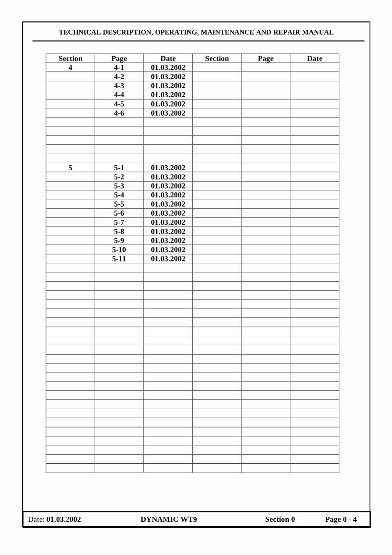
TECHNICAL DESCRIPTION, OPERATING, MAINTENANCE AND REPAIR MANUAL
Section Page Date Section Page Date 4 4-1 01.03.2002 4-2 01.03.2002 4-3 01.03.2002
4-4 01.03.2002 4-5 01.03.2002 4-6 01.03.2002
5 5-1 01.03.2002 5-2 01.03.2002 5-3 01.03.2002 5-4 01.03.2002 5-5 01.03.2002
5-6 01.03.2002 5-7 01.03.2002 5-8 01.03.2002 5-9 01.03.2002 5-10 01.03.2002 5-11 01.03.2002
Date: 01.03.2002 DYNAMIC WT9 Section 0 Page 0 - 4

TECHNICAL DESCRIPTION, OPERATING, MAINTENANCE AND REPAIR MANUAL 0.3 CONTENTS
Section
GENERAL 0
TECHNICAL DESCRIPTION 1
OPERATION 2
MAINTENANCE 3
REPAIRS 4
APPENDICES 5
Date: 01.03.2002 DYNAMIC WT9 Section 0 Page 0 - 5
TECHNICAL DESCRIPTION, OPERATING, MAINTENANCE AND REPAIR MANUAL
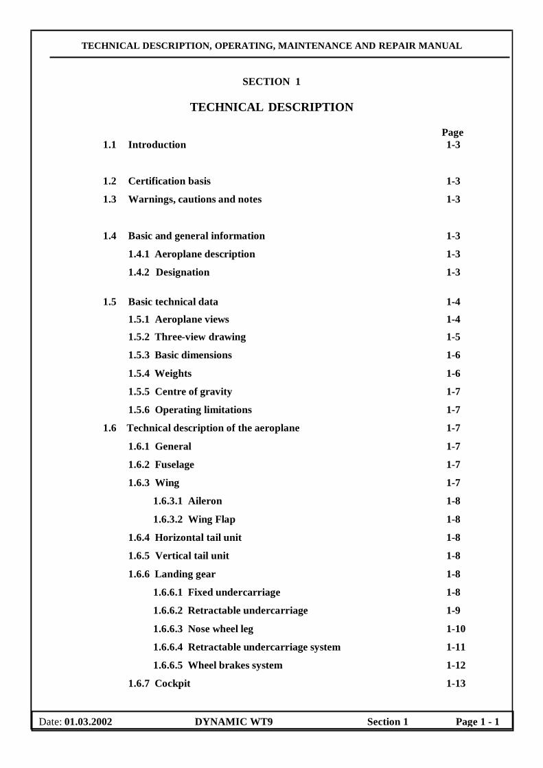
SECTION 1
TECHNICAL DESCRIPTION
Page
1.1 Introduction 1-3
1.2 Certification basis 1-3
1.3 Warnings, cautions and notes 1-3
1.4 Basic and general information 1-3
1.4.1 Aeroplane description 1-3
1.4.2 Designation 1-3 1.5 Basic technical data 1-4
1.5.1 Aeroplane views 1-4
1.5.2 Three-view drawing 1-5
1.5.3 Basic dimensions 1-6
1.5.4 Weights 1-6
1.5.5 Centre of gravity 1-7
1.5.6 Operating limitations 1-7
1.6 Technical description of the aeroplane 1-7
1.6.1 General 1-7
1.6.2 Fuselage 1-7
1.6.3 Wing 1-7
1.6.3.1 Aileron 1-8
1.6.3.2 Wing Flap 1-8
1.6.4 Horizontal tail unit 1-8
1.6.5 Vertical tail unit 1-8
1.6.6 Landing gear 1-8
1.6.6.1 Fixed undercarriage 1-8
1.6.6.2 Retractable undercarriage 1-9
1.6.6.3 Nose wheel leg 1-10
1.6.6.4 Retractable undercarriage system 1-11
1.6.6.5 Wheel brakes system 1-12
1.6.7 Cockpit 1-13
Date: 01.03.2002 DYNAMIC WT9 Section 1 Page 1 - 1
TECHNICAL DESCRIPTION, OPERATING, MAINTENANCE AND REPAIR MANUAL
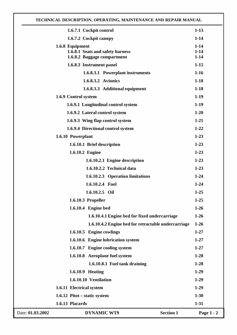
1.6.7.1 Cockpit control 1-13
1.6.7.2 Cockpit canopy 1-14
1.6.8 Equipment 1-14 1.6.8.1 Seats and safety harness 1-14
1.6.8.2 Baggage compartment 1-14
1.6.8.3 Instrument panel 1-15
1.6.8.3.1 Powerplant instruments 1-16
1.6.8.3.2 Avionics 1-18
1.6.8.3.3 Additional equipment 1-18
1.6.9 Control system 1-19
1.6.9.1 Longitudinal control system 1-19
1.6.9.2 Lateral control system 1-20
1.6.9.3 Wing flap control system 1-21
1.6.9.4 Directional control system 1-22
1.6.10 Powerplant 1-23
1.6.10.1 Brief description 1-23
1.6.10.2 Engine 1-23
1.6.10.2.1 Engine description 1-23
1.6.10.2.2 Technical data 1-23
1.6.10.2.3 Operation limitations 1-24
1.6.10.2.4 Fuel 1-24
1.6.10.2.5 Oil 1-25
1.6.10.3 Propeller 1-25
1.6.10.4 Engine bed 1-26
1.6.10.4.1 Engine bed for fixed undercarriage 1-26
1.6.10.4.2 Engine bed for retractable undercarriage 1-26
1.6.10.5 Engine cowlings 1-27
1.6.10.6 Engine lubrication system 1-27
1.6.10.7 Engine cooling system 1-27
1.6.10.8 Aeroplane fuel system 1-28
1.6.10.8.1 Fuel tank draining 1-28
1.6.10.9 Heating 1-29
1.6.10.10 Ventilation 1-29
1.6.11 Electrical system 1-29
1.6.12 Pitot – static system 1-30
1.6.13 Placards 1-31
Date: 01.03.2002 DYNAMIC WT9 Section 1 Page 1 - 2
TECHNICAL DESCRIPTION, OPERATING, MAINTENANCE AND REPAIR MANUAL
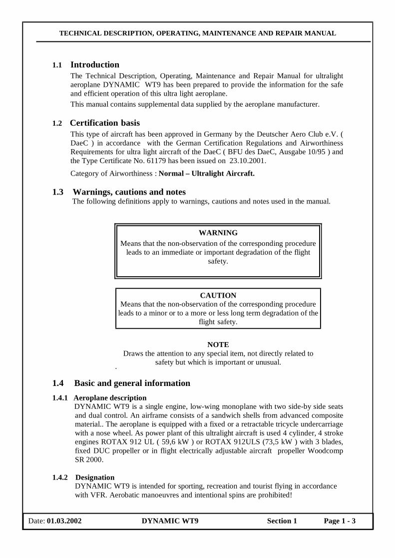
1.1 Introduction The Technical Description, Operating, Maintenance and Repair Manual for ultralight aeroplane DYNAMIC WT9 has been prepared to provide the information for the safe and efficient operation of this ultra light aeroplane. This manual contains supplemental data supplied by the aeroplane manufacturer.
1.2 Certification basis
This type of aircraft has been approved in Germany by the Deutscher Aero Club e.V. ( DaeC ) in accordance with the German Certification Regulations and Airworthiness Requirements for ultra light aircraft of the DaeC ( BFU des DaeC, Ausgabe 10/95 ) and the Type Certificate No. 61179 has been issued on 23.10.2001.
Category of Airworthiness : Normal – Ultralight Aircraft.
1.3 Warnings, cautions and notes The following definitions apply to warnings, cautions and notes used in the manual.
WARNING Means that the non-observation of the corresponding procedure
leads to an immediate or important degradation of the flight safety.
CAUTION
Means that the non-observation of the corresponding procedure leads to a minor or to a more or less long term degradation of the
flight safety.
NOTE Draws the attention to any special item, not directly related to
safety but which is important or unusual. 1.4 Basic and general information 1.4.1 Aeroplane description
DYNAMIC WT9 is a single engine, low-wing monoplane with two side-by side seats and dual control. An airframe consists of a sandwich shells from advanced composite material.. The aeroplane is equipped with a fixed or a retractable tricycle undercarriage with a nose wheel. As power plant of this ultralight aircraft is used 4 cylinder, 4 stroke engines ROTAX 912 UL ( 59,6 kW ) or ROTAX 912ULS (73,5 kW ) with 3 blades, fixed DUC propeller or in flight electrically adjustable aircraft propeller Woodcomp SR 2000.
1.4.2 Designation
DYNAMIC WT9 is intended for sporting, recreation and tourist flying in accordance with VFR. Aerobatic manoeuvres and intentional spins are prohibited!
Date: 01.03.2002 DYNAMIC WT9 Section 1 Page 1 - 3
TECHNICAL DESCRIPTION, OPERATING, MAINTENANCE AND REPAIR MANUAL
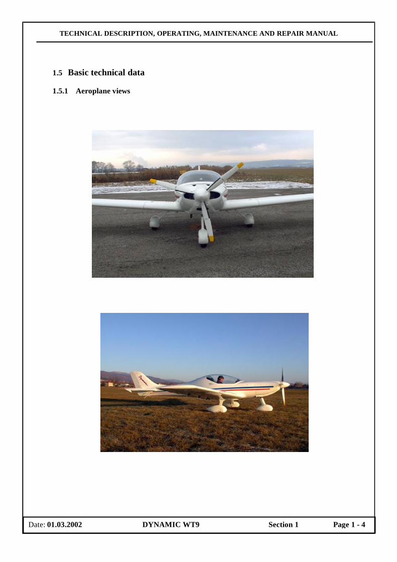
1.5 Basic technical data 1.5.1 Aeroplane views
Date: 01.03.2002 DYNAMIC WT9 Section 1 Page 1 - 4

TECHNICAL DESCRIPTION, OPERATING, MAINTENANCE AND REPAIR MANUAL
1.5.2 Three-view drawing
Date: 01.03.2002 DYNAMIC WT9 Section 1 Page 1 - 5

TECHNICAL DESCRIPTION, OPERATING, MAINTENANCE AND REPAIR MANUAL
1.5.3 Basic dimensions
Wing Wing span..…………...………………………………... 9,000 m Wing area…............................................………………. 10,300 m2 Wing aspect ratio.........................................…………… 7,82 Aerodynamic mean chord ( MAC )……...…………….. 1,185 m Aileron Aileron span………………………………….………… 1,250 m Aileron area...………………………………………….. 0,273 m2 Wing flap Flap span..……………………………………………… 2,280 m Flap area.……………………………………………….. 0,750 m2 Fuselage Length..………………………………………………… 6,400 m Width..…………………………………………………. 1,180 m Height…...……………………………………………... 2,000 m Horizontal tail unit Horizontal tail span…...………………………………... 2,400 m Horizontal tail area…………………………………….. 1,680 m2 Elevator area……………...……………………………. 0,500 m2 Vertical tail unit Height.…………...………………………………….…. 1,022 m Vertical tail area ……………………………………….. 1,020 m2 Rudder area………………..…………………………… 0,360 m2 Landing gear Wheel spacing……………………...…………………... 2,270 m Wheel base.…………………………………………….. 1,490 m Main wheel diameter ………………………………….. 0,350 m Nose wheel diameter ………………………………….. 0,320 m
1.5.4 Weights
Empty weight ( with rescue system and standard instrument equipment )
( Model Club/Tow………………………………….. 259/268 kg ( Model Speed……………………………………… 270 kg
Maximum take-off weight ……..……………………………………… 450 kg Maximum landing weight ……..……………………………………… 450 kg Fuel weight ( 75 litres )……………………………………………….. 52 kg
Date: 01.03.2002 DYNAMIC WT9 Section 1 Page 1 - 6
TECHNICAL DESCRIPTION, OPERATING, MAINTENANCE AND REPAIR MANUAL
Maximum weight in Baggage Compartment………………………… 10 kg
NOTE Actual empty weight is stated on the placard „ LOAD LIMITS „
stuck in the cockpit.
1.5.5 Centre of gravity
Empty aeroplane .….…………………………. 12 ± 2% SAT Position of C.G. in flight …………………….. 20 ÷ 30% SAT
1.5.6 Operating limitations
Refer to the Aeroplane Flight Manual ( AFM ), Section 2 for more details about the following operating limits: - Airspeed limits, - Weights limits, - C.G. range limits, - Approved manoeuvres.
1.6 Technical description of the aeroplane
1.6.1 General
An airframe consists of a sandwich shells from advanced composite material. The shell is of three layer construction. The external and internal shell layers are made of a glass and a carbon fiber fabricses, which are saturated with a resin. Between them there is a filling from a hard foam panels. The shells are formed in negative forms and they are heat treatmented 12 hours at temperature 54 °C for resin-harden.
1.6.2 Fuselage The fuselage sandwich shell is divided in the symmetry plane. The fuselage cross-section are parabolic curves. The cockpit is reinforcemented with hollow profile from advanced composite material. The back rest of the crew and the central pedestal are glued and together with the shells they create reinforcement element of the airframe. The fin is made together with the fuselage. The wing central panel is fixed at the fuselage. There is the integral tank in the forward box of the wing central panel. The back box of the wing central panel is used as room for main legs of the retractable undercarriage. There are stiffening ribs in the back box of the wing central panel for gripping of the legs of the fixed undercarriage. A rescue system with ejection of the rescue parachute through removable cover may be located behind the fire wall of the power plant (if is installed). A horizontal tail is fixed at the fuselage too. The baggage compartment is situated behind the seats. There is the frame with the access hole into the rear part of the fuselage. The Perspex canopy is glued on the composite frame. The canopy is attached to the nose section of the fuselage by pins which make it possible for the canopy to be tilted forward. For easier manipulation, the weight of the canopy is counterbalanced by two gas struts which allow it to open effortlessly. The
Date: 01.03.2002 DYNAMIC WT9 Section 1 Page 1 - 7
TECHNICAL DESCRIPTION, OPERATING, MAINTENANCE AND REPAIR MANUAL
engine section in the nose is separated from the cockpit by a firewall which the engine bed is attached to.
1.6.3 Wing A construction of the wing is two – box type ( the main spar caps are made from the carbon rods and one auxiliary girder ). A torsion box is glass fibre reinforced plastics sandwich construction. The spars of right and left wings are joined to the wing central panel spar with the help of two pins. The outer pin is inserted through the room for main legs of the retractable undercarriage ( at model SPEED ) or through the access hole on the lower wing surface ( at model CLUB). The inner pin is inserted through the hole in the cockpit below pilot seat. The third join point is the pin of the auxiliary girder. The Pitot-static head is located on the right wing leading edge.
1.6.3.1 Aileron
A construction of the aileron is the sandwich shell structure type. The aileron is attached to the upper surface of the wing shell with three hinges from advanced composite material. The movement by means of the rod is transmitted into the root rib. The control-surface weight balance is attached on the aileron tip rib. The deflections of the ailerons are differentiated 1: 1,6 .
1.6.3.2 Wing flap
The wing flap is the slotted flap type, with the low lying point of rotation. A construction of the wing flap is the sandwich shell structure type. The flap is attached to the wing with four hinges. The movement by means of the rod is transmitted into the wing flap root rib. The flap control lever has four positions: retracted, take-off with flap deflection 15°, landing position with flap deflection 24 ° and landing position with flap deflection 35°.
1.6.4 Horizontal tail unit
The horizontal tail unit consists of a stabilizer and elevator. The stabilizer consists of the sandwich shells from advanced composite material. The stabilizer is fixed at the fin. The elevator consists of two parts, which are joined together by means of the elevator control. The control-surface weight balance are attached on the tip of both parts of the elevator.
1.6.5 Vertical tail unit
The vertical tail unit consists of the fin and rudder and has trapezoidal shape. The fin is an integral part of the fuselage rear section. The rudder consists of a sandwich shells from advanced composite material with the control-surface weight balance. The ruder is attached by three hinges at the fin.
1.6.6 Landing gear DYNAMIC WT9, model Club is equipped with fixed tricycle landing gear and model Speed is equipped with retractable tricycle landing gear, which is actuated by a hydraulic system by the help of the electrical driven hydraulic pump.
1.6.6.1 Fixed undercarriage The main landing gear uses the legs, which are formed as a fibber-glass springs and are fixed in the fuselage casing under the seats on the stiffening ribs in the back box of the wing central panel. The diameter of the main wheels is 350 mm and they are covered with laminated fairings. The main wheels on both legs are equipped with hydraulic disc brakes. The main wheel are braked by hydraulic brakes with main
Date: 01.03.2002 DYNAMIC WT9 Section 1 Page 1 - 8

TECHNICAL DESCRIPTION, OPERATING, MAINTENANCE AND REPAIR MANUAL
hydraulic face ram, which is located beyond the seats. The main wheel brakes are actuated via the handle on the pedestal between the pilot seats. This handle actuates the parking brake too. Systems are actuated via the handle on the pedestal between the pilot seats. The nose wheel leg consists of the steel tube and the carbon fork, where is located nose wheel with diameter 300 mm. The nose wheel leg is supported on bearings ( upper and down ) and is controlled by means of the rods connected to the rudder pedals. The springing is carried out with rubber rope and with the flexible element, which is located in the upper nose wheel bearing. The nose wheel is covered with laminated fairing.
1.6.6.2 Retractable undercarriage Main undercarriage consists of the welded steel leg ( B ) , the arm ( R) with the wheel and the flexible element ( FB ) . The main leg is fixed into the fitting of the wing central panel main spar in front, and into the fitting of the auxiliary girder in rear. The wheel is equipped with disc brake ( SB ). The retraction of the undercarriage is carried out with help of the hydraulic face rams inside to the symmetry plane of the aeroplane. The pistons of the hydraulic face rams are connected with the drag stay, which is equipped with the spiral spring ( F ) . This spring pushes the drag stay during of the undercarriage extension into the arrested position. The emergency extension of the undercarriage is carried out by own mass with the help a three-way valve. The drag stay is arrested with help of the springs.
Main leg of the retractable undercarriage
Date: 01.03.2002 DYNAMIC WT9 Section 1 Page 1 - 9
B
F
FB
R
SB

TECHNICAL DESCRIPTION, OPERATING, MAINTENANCE AND REPAIR MANUAL
1.6.6.3 Nose wheel leg
The nose wheel leg ( B) is fixed into the engine bed. The nose wheel leg is the wheel arm towed type. The damping of the arm is carried out with the flexible elements from polyurethane, which are located in the tube of the leg ( B ). The nose undercarriage leg is retracted backwards. The drag stay ( KS ), which is connected with the piston of the hydraulic face ram provides for the movement of the nose undercarriage. The gas strut ( GF ) provides for the emergency extension of the nose undercarriage. This gas strut extrudes the drag stay into the arrested position. The control of the nose undercarriage leg is carried out with help of the control cables ( KZ ) „Cabelcraft“ type connected with the rudder pedals.
The nose wheel leg of the retractable undercarriage
Date: 01.03.2002 DYNAMIC WT9 Section 1 Page 1 - 10
B
KZ GF
KS

TECHNICAL DESCRIPTION, OPERATING, MAINTENANCE AND REPAIR MANUAL
1.6.6.4 Retractable undercarriage system
Retractable undercarriage system is hydraulic and consists of the following elements: - the electrical driven hydraulic pump ( 12 V DC ). - the three-way valve - the pressure switch - three hydraulic face rams for both main legs and for one nose wheel leg - the pressure lines - the overswitch no.1 - the overswitch no. 2
The hydraulic system schematic of the retractable undercarriage is shown in the following figure:
The power is supplied from the battery to the overswitch S1 in the up position on the instrument panel labelled “Hydraulic On”, which switch on the hydraulic pump by means of the pressure switch and the relay. The pressure switch switches off the power after reaching of desired pressure. The overswitch S1 in the down position labelled “Emergency extension of L/G” switches on the emergency extension of the undercarriage. The emergency extension of the undercarriage is carried out by own mass with the help a three-way valve. The drag stay is arrested with help of the springs. The other overswitch S2 controls the direction of the pressure fluid movement for extension or retraction of the undercarriage. The pressure fluid proceeds via the three-way valve to the one or another side of the hydraulic face ram. Both sides of the hydraulic face ram are without pressure at the emergency extension of the undercarriage.
Fig..... The hydraulic system scheme of the retractable undercarriage
Date: 01.03.2002 DYNAMIC WT9 Section 1 Page 1 - 11

TECHNICAL DESCRIPTION, OPERATING, MAINTENANCE AND REPAIR MANUAL
1.6.6.5 Wheel brake system
Both wheels on main undercarriage are equipped with the hydraulic disc brakes. The brake disc is bolted on the rim inner part with three screws. The hydraulic brake cylinders ( BZ ) are actuated with the pressure of the hydraulic fluid. The source of the pressure is the main brake hydraulic face ram ( HZ ), which is located beyond the rear frame of the baggage compartment. The main brake hydraulic face ram ( HZ ) is actuated via the handle on the pedestal between the pilot seats. The movement of the lever is transmitted with the cable. The pressure fluid is distributed through the hoses ( L ). This handle actuates the parking brake too.
Fig....Brake system scheme
1.6.7 Cockpit The side wall of the seats together with the pedestal between the seats and a back supporter of the seats are glued into the fuselage construction as the frame. The seats with a thin upholstery interior cockpit sides are covered with padded panels with pockets. The bottom of the seats are removable for the access to the aggregates, which are mounted below the seats.
Date: 01.03.2002 DYNAMIC WT9 Section 1 Page 1 - 12

TECHNICAL DESCRIPTION, OPERATING, MAINTENANCE AND REPAIR MANUAL
1.6.7.1 Cockpit control The control sticks are supported on the torsional tube. The attachments of this torsional tube are fixed to the main spar of the wing central panel. The flap control lever, elevator trim tab lever and the main wheel brakes handle are located on the pedestal between the pilot seats. The standard instrument panel arrangement is shown in the following figure. Instrument panel arrangement is described in par. 1.6.8.3.
Fig... The cockpit controls
1. Control stick/ push button of the transmission 8. Seat and safety harness. 2. Rudder pedals 9. Instrument panel 3. Elevator trim control lever 10.Ventilation sliding window 4. Brake control lever 11.Ventilation 5. Wing flaps control lever 12. Fuel cock 6. Pocket 13. Chock
7. Headset socket / jack 14. Tow cable release
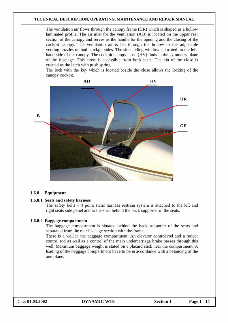
1.6.7.2 Cockpit canopy The cockpit canopy consists of one part. The Perspex canopy is glued on the composite frame. The canopy is attached to the nose section of the fuselage by two pins (B) which make it possible for the canopy to be tilted forward. For easier manipulation, the weight of the canopy is counterbalanced by two gas struts (GF) which allow it to open effortlessly. On the lower frame there are handles outside the canopy. The canopy is equipped with a lock on the upper rear section of the frame.
Date: 01.03.2002 DYNAMIC WT9 Section 1 Page 1 - 13
13 14
TECHNICAL DESCRIPTION, OPERATING, MAINTENANCE AND REPAIR MANUAL
The ventilation air flows through the canopy frame (HR) which is shaped as a hollow laminated profile. The air inlet for the ventilation (AO) is located on the upper rear section of the canopy and serves as the handle for the opening and the closing of the cockpit canopy. The ventilation air is led through the hollow to the adjustable venting nozzles on both cockpit sides. The side sliding window is located on the left-hand side of the canopy. The cockpit canopy close (HV) finds in the symmetry plane of the fuselage. This close is accessible from both seats. The pin of the close is created as the latch with push spring. The lock with the key which is located beside the close allows the locking of the canopy cockpit.
1.6.8 Equipment
1.6.8.1 Seats and safety harness The safety belts – 4 point static harness restrain system is attached to the left and right seats side panel and to the strut behind the back supporter of the seats.
1.6.8.2 Baggage compartment
The baggage compartment is situated behind the back supporter of the seats and separated from the rear fuselage section with the frame. There is a well in the baggage compartment. An elevator control rod and a rudder control rod as well as a control of the main undercarriage brake passes through this well. Maximum baggage weight is stated on a placard stick near the compartment. A loading of the baggage compartment have to be in accordance with a balancing of the aeroplane.
Date: 01.03.2002 DYNAMIC WT9 Section 1 Page 1 - 14
HR
GF
AO
B
HV

TECHNICAL DESCRIPTION, OPERATING, MAINTENANCE AND REPAIR MANUAL
1.6.8.3 Instrument panel The minimum required instrument equipment is:
- Airspeed Indicator, Altimeter, Magnetic Compass, Fuel Quantity Indicator For detail description of exact aircraft see the Flight manual.
The flight and navigation instruments are mounted as an option of the customer ( but with respect to the weight limitation and C.G. of the ultra light aircraft ). A magnetic field may be changed after an additional installation of the instruments, whereupon a compass compensation must be done.
Fig. Instrument panel
1. Landing Gear Check Light
2. Charge 3. Net Light 4. Bank Indicator 5. Airbox Temperature 6. Airspeed Indicator 7. Tachometer 8. Variometer 9. Altimeter 10. Landing Gear Control 11. Propeller Control
Constant Speed Indicator 12. Master Switch 13. Ignition 14. Starter
15. Intercom Control 16. Tow Release 17. Throttle Lever 18. Choke Lever 19. Oil Cooler Flap Lever 20. Carburettor Heat Control 21. Heating 22. Main Fuel Coke 23. Trim Control Lever 24. Flap Control Lever 25. Brake Lever 26. Control Column 27. VHF button 28. Fuel Quantity Indicator 29. Fuel Pressure 30. Manifold Pressure
31. Cylinder-Head Temperature Indicator
32. Oil Temperature Indicator
33. Oil Pressure Indicator 34. Hydraulic Pump 35. Auxiliary Electrical Fuel
Pump 36. Landing Lights Switch 37. Navigation Lights Switch 38. Wing Tip Strobe Lights
Switch 39. 12 V Stage Pocket 40. Fuses 41. Magnetic Compass 42. Rescue System Handle
Date: 01.03.2002 DYNAMIC WT9 Section 1 Page 1 - 15
42
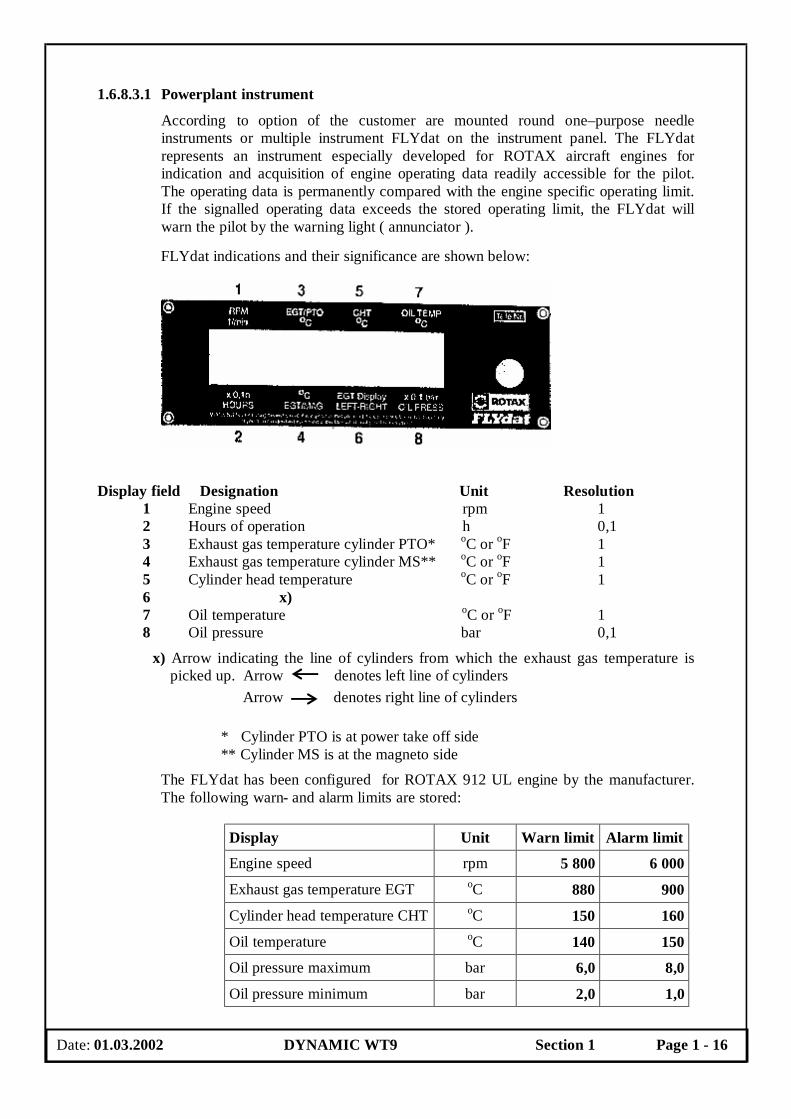
1.6.8.3.1 Powerplant instrument
According to option of the customer are mounted round one–purpose needle instruments or multiple instrument FLYdat on the instrument panel. The FLYdat represents an instrument especially developed for ROTAX aircraft engines for indication and acquisition of engine operating data readily accessible for the pilot. The operating data is permanently compared with the engine specific operating limit. If the signalled operating data exceeds the stored operating limit, the FLYdat will warn the pilot by the warning light ( annunciator ).
FLYdat indications and their significance are shown below:
Display field Designation Unit Resolution 1 Engine speed rpm 1 2 Hours of operation h 0,1 3 Exhaust gas temperature cylinder PTO* oC or oF 1 4 Exhaust gas temperature cylinder MS** oC or oF 1 5 Cylinder head temperature oC or oF 1
6 x) 7 Oil temperature oC or oF 1 8 Oil pressure bar 0,1
x) Arrow indicating the line of cylinders from which the exhaust gas temperature is picked up. Arrow denotes left line of cylinders
Arrow denotes right line of cylinders
* Cylinder PTO is at power take off side ** Cylinder MS is at the magneto side
The FLYdat has been configured for ROTAX 912 UL engine by the manufacturer. The following warn- and alarm limits are stored:
Display Unit Warn limit Alarm limit
Engine speed rpm 5 800 6 000
Exhaust gas temperature EGT oC 880 900
Cylinder head temperature CHT oC 150 160
Oil temperature oC 140 150
Oil pressure maximum bar 6,0 8,0
Oil pressure minimum bar 2,0 1,0
Date: 01.03.2002 DYNAMIC WT9 Section 1 Page 1 - 16

TECHNICAL DESCRIPTION, OPERATING, MAINTENANCE AND REPAIR MANUAL
2
The FLYdat has been configured for ROTAX 912 ULS engine by the manufacturer. The following warn- and alarm limits are stored:
Display Unit Warn limit Alarm limit
Engine speed rpm 5 800 6 000
Exhaust gas temperature EGT oC 880 900
Cylinder head temperature CHT oC 135 150
Oil temperature oC 130 145
Oil pressure maximum bar 6,0 8,0
Oil pressure minimum bar 2,0 1,0
Distinguish between three ranges of readings control:
Colour range Significance Green (standard operation )
All readings are below or above ( min. oil pressure ) the warn limits programmed.
Yellow ( exceeding of warn limits )
If one or more readings exceed the programmed warn limit, then the readings appears flashing on the display , and simultaneously the alarm output is periodically ( 0,25 sec. ) switched on and off, until no readings exceed warn limit.
Red ( exceeding of alarm limits )
If one or more readings exceed the programmed alarm limit, then the readings appear flashing on the display and simultaneously the alarm output is permanently activated until no reading exceeds the warn limit.
If one or more alarm limits have been exceed, or the reading on the meter of the operating hours has surpassed the programmed TBO, the maintenance message reads as follows: „Service !“ .
CAUTION Disregard of the warn- and alarm signals might result in injuries
or endanger the life of operator or third party. BOMBARDIER-ROTAX as manufacturer, warrants every FLYdat for a period of not more than 9 consecutive months for private use owners or 12 consecutive months from date of shipment of the manufacturer or the first 150 operation hours.
Date: 01.03.2002 DYNAMIC WT9 Section 1 Page 1 - 17
TECHNICAL DESCRIPTION, OPERATING, MAINTENANCE AND REPAIR MANUAL
3
Powerplant instrument markings and their colour code significance are shown below:
Instrument
Unit
Red Line Minimum
Limit
Green Arc Normal
Operating
Yellow Arc
Caution Range
Red Line Maximum
Limit
Tachometer rpm 1 400 1 800 – 5 500 5500–5800 5 800
Oil temperature indicator
oC 50 90 – 110 50 - 90
110 - 1401)
110 – 1302)
140 1)
130 2)
Cylinder-head temperature indicator
oC
150 1)
135 2)
Fuel-pressure indicator
bar 0,15 0,4
Oil-pressure indicator
bar 1,5 1,5 – 5 5 – 7 7
Fuel quantity indicator l
Yellow light annunciator above the fuel indicator will be illuminated with the remaining fuel of 7 litre in each fuel tank.
1) Indication is valid for ROTAX 912 UL engine 2) Indication is valid for ROTAX 912 ULS engine
1.6.8.3.2 Avionics The following avionics are mounted in the aeroplane: radios and intercom. These equipment must be connected with the headphones and with the antenna. The aeroplane might be equipped with other instruments ( GPS, transponder, or board computer ). The flight and navigation instruments are mounted as an option of the customer ( but with respect to the weight limitation of the ultra light aircraft ). Refer to the Manuals supplied with above mentioned instruments for right operation of the instruments and for more details.
1.6.8.3.3 Additional equipment The rescue system USH 52 S Speed Softpack from the company USH – záchranné systémy s.r.o Praha can be mounted as the miscellaneous equipment of the aeroplane DYNAMIC WT 9. This rescue system is designed for the ultralights aircraft with maximum weight up to 520 kg and with maximum speed of using 300 km/hour. The triconical type of parachute with 30 parachute gores and square area 105 m2 with slider is used for the rescue system. The descent rate of the opened parachute is 6,5 m/sec. The container dimension is 260 x 150 x 500 mm and the total weight is 12,5 kg. The solid fuel rocket engine UPI – PFE – 400 with total impulse of 400 N sec and time of the burning 0.85 sec is used. The life time of the rescue system is 10 years with the repacking interval is 5 years.
Date: 01.03.2002 DYNAMIC WT9 Section 1 Page 1 - 18
TECHNICAL DESCRIPTION, OPERATING, MAINTENANCE AND REPAIR MANUAL
4
1.6.9 Control system
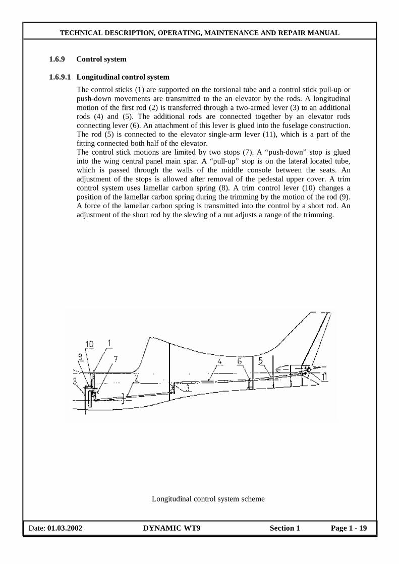
1.6.9.1 Longitudinal control system
The control sticks (1) are supported on the torsional tube and a control stick pull-up or push-down movements are transmitted to the an elevator by the rods. A longitudinal motion of the first rod (2) is transferred through a two-armed lever (3) to an additional rods (4) and (5). The additional rods are connected together by an elevator rods connecting lever (6). An attachment of this lever is glued into the fuselage construction. The rod (5) is connected to the elevator single-arm lever (11), which is a part of the fitting connected both half of the elevator. The control stick motions are limited by two stops (7). A “push-down” stop is glued into the wing central panel main spar. A “pull-up” stop is on the lateral located tube, which is passed through the walls of the middle console between the seats. An adjustment of the stops is allowed after removal of the pedestal upper cover. A trim control system uses lamellar carbon spring (8). A trim control lever (10) changes a position of the lamellar carbon spring during the trimming by the motion of the rod (9). A force of the lamellar carbon spring is transmitted into the control by a short rod. An adjustment of the short rod by the slewing of a nut adjusts a range of the trimming.
Longitudinal control system scheme
Date: 01.03.2002 DYNAMIC WT9 Section 1 Page 1 - 19

TECHNICAL DESCRIPTION, OPERATING, MAINTENANCE AND REPAIR MANUAL
5
1.6.9.2 Lateral control system
A control stick lateral motion (1) is transferred by rod (2) into a pin joint (BV), which allows a disconnection of the rod in case of a derigging of a wing. An access to this joint (BV) is allowed through an access hole at a model with a fixed undercarriage and through a main wheel well at a model with a retractable undercarriage. Long rod (3) guides from the end of the wing central panel to the two-arm lever (4), which a console with the bearings is attached at the wing main spar. This lever provides a necessary differentiation of the aileron deflections. Two-armed lever angular displacement is transferred at aileron by short rod (5). A longitudinal movement of a short rod is transferred into an aileron root rib, which a point of rotation is below a upper surface wing. The long rod (3) is guided in a sliding guide rollers (6) which are located in the wing root rib and in the wing auxiliary rib. Its guide surfaces are equipped with a riveted sliding capsulars on a rod. The range of the control stick deflection is adjusted by stops (AS) on the consoles of the torsional tube (TR). The stops are screws type with the fastening nut.
Lateral control system scheme.1- Control stick, 2- Rod in the wing central panel, 3- Rod in the wing, 4- Two-arm lever, 5- Aileron rod, 6- Sliding guide rollers,
7- Sliding bearings BV- Split pin joint, QR- Aileron
Date: 01.03.2002 DYNAMIC WT9 Section 1 Page 1 - 20
BV

TECHNICAL DESCRIPTION, OPERATING, MAINTENANCE AND REPAIR MANUAL
1.6.9.3 Wing flap control system The wing flaps are controlled by a flap control lever (1) located on the pedestal between the seats. Set flap position is locked by the deflection of the flap control lever into the appropriate recesses on the pedestal cover, where a lever is pushed by a spring. The lever deflection is transferred at a longitudinal movement of a rod (3) to the torsional tube (5), which transfers this motion symmetrically on both wing flaps. The torsional tube (5) is supported at three sliding bearings (7). Two short rods (6) with the adjustable rod ends provide for a connection of the torsional tube with the wing flaps. These adjustable rod ends allow the symmetrical deflections adjustment of both flaps. The rods (6) are jointed with the flap control lever by means of the disconnection pin, which is secured by a cotter pin. An access to this joint is allowed by the wing flap deflection into the maximum lower landing position.
Wing flap control system scheme
1- Flap control lever,2- Changing gate, 3- Rod, 4- Arm of the torsional tube, 5- Torsional tube, 6- Short rod,
7- Sliding bearing, 8- Arm joint bolt, 9- Flap arm, KL- Flap
Date: 01.03.2002 DYNAMIC WT9 Section 1 Page 1 - 21

TECHNICAL DESCRIPTION, OPERATING, MAINTENANCE AND REPAIR MANUAL
1.6.9.4 Directional control system
The rudder pedals are attached on the cockpit floor at the model with a fixed undercarriage. In case of the retractable undercarriage, due to a present of a nose wheel leg well, the control system is attached on the lateral reinforcement. For adjustment is necessary pull-up a pin (RB) pushed by spring from a pressure, slew a pedal (P) into the required position, than push the pin (RB) again into the appropriate hole. The pedal motions are transferred from the lateral torsional tubes (QR) to the rudder by means of the control cables. The control cables are guided through a polyurethane casing, which is attached into the fuselage structure. The rudder control is connected with nose wheel undercarriage control by means of two short rods or by means of control cables „Cablecraft“ type at a model with retractable undercarriage.
Adjustment of the rudder pedals
Date: 01.03.2002 DYNAMIC WT9 Section 1 Page 1 - 22
P
RB
QR

TECHNICAL DESCRIPTION, OPERATING, MAINTENANCE AND REPAIR MANUAL
1.6.10 Powerplant 1.6.10.1 Brief description
Standard powerplant consists of 4 cylinder horizontally opposed, 4-stroke engine ROTAX 912 UL with power 59,6 kW or engine ROTAX 912 ULS with power 73 kW and a three blades, fixed pitch or in flight electrically adjustable aircraft propeller DUC or SR 2000. The standard powerplant is shown on the following figure:
1.6.10.2 Engine
1.6.10.2.1 Engine description ROTAX 912 UL / 912 ULS is 4-stroke, 4 cylinder horizontally opposed, spark ignition engine, one central camshaft-push-rods-OHV. Liquid cooled cylinder heads, ram air cooled cylinders. Dry sump forced lubrication. The engine is fitted with electric starter, AC generator, mechanical fuel pump and the reduction gear with integrated shock absorber. Refer to the Operator’s Manual for all versions of ROTAX 912 for more details about versions difference.
1.6.10.2.2 Technical data Engine Manufacturer : ROTAX-Bombardier, Gunskirchen
Engine Model: Rotax 912 UL or 912 ULS
Power:
Maximum take-off: 59,6 kW/80 hp at 5800 rpm ( for ULS 73,5 kW/100 hp )
Maximum continuous: 58 kW/78 hp at 5500 rpm ( for ULS 69 kW/94 hp )
Cruising: 53 kW/71 hp at 4800 rpm
Date: 01.03.2002 DYNAMIC WT9 Section 1 Page 1 - 23
TECHNICAL DESCRIPTION, OPERATING, MAINTENANCE AND REPAIR MANUAL
1.6.10.2.3 Operation limitations 912 UL 912ULS Engine speed: Maximum take-off 5800 rpm, max. 5 min 5800 rpm, max. 5 min Maximum continuous 5500 rpm 5500 rpm Idling ≈1400 rpm ≈1400 rpm Cylinder head temperature minim. 60°C maxim.140°C (135°C) ( FLYdat CHT reading)
Oil temperature maxim. 140°C (130°C) ( FLYdat OIL TEMP reading) minim. 50° C (50° C) ( FLYdat OIL TEMP reading) optimum 90-110° C (optimum 90-110° C ) Oil pressure maxim. 7 bar ( for a short period admissible at cold start) minim. 1,5 bar (minim. 1,5 bar) normal 2,0 ÷5,0 bar ( above 3500 rpm ) (2,0 ÷ 5,0 bar ) Engine start, operating temperature: max. 50° C (max. 50° C ) min. -25° C (min. -25° C ) Fuel pressure: max. 0,4 bar (max. 0,4 bar ) min. 0,15 bar (min. 0,15 bar ) 1.6.10.2.4 Fuel
912 UL/A/F 912 ULS/S Minimum octane number 90 Minimum octane number 95 EN 228 Normal –––––––––––––––– EN 228 SUPER EN 228 SUPER EN 228 SUPER plus EN 228 SUPER plus AVGAS 100 LL AVGAS 100 LL
Due to the higher lead content in AVGAS, the wear of the valve seats, the deposits in combustion chamber and lead sediments in the lubrication system will increase. Therefore, use AVGAS only if you encounter problems with vapour lock or if the other fuel types are not available. Risk of a vapour formation if using winter fuel for summer operation.
Left tank ( l ) Right tank ( l )
The total quantity of fuel in the tank 37,5 37,5
Unusable fuel in the tank 0,5 0,5
Unusable fuel during approach 1,9 1,9
The total usable quantity of fuel in the tank 37,0 37,0
Date: 01.03.2002 DYNAMIC WT9 Section 1 Page 1 - 24
TECHNICAL DESCRIPTION, OPERATING, MAINTENANCE AND REPAIR MANUAL
1.6.10.2.5 Oil Oil grade: motorcycle oil of a registered brand with gear additives. Use only oil
with API classification „SF“ or „SG“! If using aircraft engine oil, than only blended one. Due to the high stresses in the reduction gears, oils with gear additives such as high performance motor cycle oils are required. Heavy dry 4-stroke motor cycle oils meet all the requirements. These oils are normally no mineral oils but semi- or full synthetic oils.
Oil capacity: 3,0 litre Minimum: 2,0 litre Oil consumption: max. 0,1 l/h
WARNING Never use AVGAS LB 95 with mix full synthetic engine oils.
At the selection of suitable lubricants refer to the additional information in the Operator’s Manual for all versions of ROTAX 912.
1.6.10.3 Propeller
Standard version of aeroplane is equipped with SR 2000 is the three blades, in flight electrically adjustable aircraft propeller of a mixed structure. The propeller blades are made of a wood and the leading edges are made of a wear resistant material. The angle of blades setting is adjusted by servomotor controlled from the cockpit and it can be adjusted smoothly in range from the minimum angle intended for take-off up to maximum angle. The momentary blade angle is designated by a time of displace from 16° lower blade stop ( measured at 0,75 of a propeller semi-diameter ). A speed of displace is 0,5 °/sec. Propeller control on the instrument panel consists of panel, in which there is placed the signalisation of the direction of propeller blades adjusting, together with control diodes of small and large angle and also the switch of control. The meaning of the control diodes signals is:
Yellow control diode of adjusting the fine angle: - shines after reaching the stop at 16°, i.e. min. angle - blinks when adjusting the fine angle Red control diode of adjusting the rough angle: - shines after reaching the stop at 26°, i.e. max. angle - blinks when adjusting the rough angle Propeller Technical Data: Propeller Diameter: 1700 mm Propeller Blade Angle: 16 ÷ 26° (Range of setting angles is adjustable) Max. Propeller Speed on ground: 2550 rpm Max. Propeller Speed in flight: 2600 rpm Max. Propeller Speed on testing stand: 3200 rpm Propeller Mass: 7,8 kg Time Between Overhaul (TBO): 1200 hrs or 15 years ( whichever comes first )
Date: 01.03.2002 DYNAMIC WT9 Section 1 Page 1 - 25
TECHNICAL DESCRIPTION, OPERATING, MAINTENANCE AND REPAIR MANUAL
Additional data can be found in the Operator’s Manual for electric adjustable aircraft propeller SR 2000.
WARNING Never run the engine without propeller, this inevitably causes
engine damage and is an explosion hazard.
1.6.10.4 Engine bed
The engine bed is welded from chrome-molybdenum tubes and its producing is different for an aeroplane model with a fixed undercarriage or for an aeroplane model with a retractable undercarriage.
1.6.10.4.1 Engine bed for fixed undercarriage
The engine bed is solid and attached to the firewall with 4 bolts. The bed is spring-mounted with four rubber silentblocks.
1.6.10.4.2 Engine bed for retractable undercarriage The engine bed is two-part type. A front part is attached to the engine and with a rear part is spring-connected with rubber silentblocks and 4 bolts. The rear part is attached to the firewall and this part serves for attachment of the retractable nose wheel leg.
Date: 01.03.2002 DYNAMIC WT9 Section 1 Page 1 - 26
TECHNICAL DESCRIPTION, OPERATING, MAINTENANCE AND REPAIR MANUAL
1.6.10.5 Engine cowlings There are two laminated cowlings. The disassembly of a upper cowling is easy, just release the quick-closing locks. The quick-closing locks releases by means of a suitable screwdriver with a 90° counterclockwise slewing. The releasing starts at a rear corner with the simultaneous raising of the cowling. The quick-closing locks releases have to remain over a cowling until the disassembly of a all cowling. The lower cowling is removed after unscrew the attachment screws connecting the cooler to the cowling face side, then unscrew the attachment screws connecting the cowling to the firewall border. The coolers remain connected with the inlet hoses.
1.6.10.6 Engine lubrication system
The ROTAX 912 engine is provided with a dry sump forced lubrication system. The oil pump is driven by the camshaft. The oil pump sucks the motor oil from the oil tank via the oil cooler or LAMINOVA heat exchanger and forces if through the oil filter to the points of lubrication in the engine. The surplus oil emerging from the points of lubrication accumulates on the bottom of crankcase and is forced back to the oil by the blow-by gases. The oil tank is equipped with a venting hose. The oil temperature sensor for reading of the oil inlet temperature is located on the oil pump housing. Refer to the Operator’s Manual for all versions of ROTAX 912 for additional information.
1.6.10.7 Engine cooling system The cooling system of the ROTAX 912 engine is designed for liquid cooling of the cylinder heads and ram-air cooling of the cylinder. The cooling system of the cylinder heads is a closed circuit with an expansion tank and with a overflow bottle. The coolant flow is forced by a water pump, driven from the camshaft, from the radiator to the cylinder heads and through the LAMINOVA heat exchanger (if installed). From the top of the cylinder heads the coolant passes to the expansion tank (1). Since the standard location of the radiator (2) is below engine level, the expansion tank located on top of the engine allows for coolant expansion. The expansion tank is closed by a pressure cap (3) ( with excess pressure valve and return valve ). At temperature rise of the coolant the excess pressure valve opens and the coolant will flow via a hose at atmospheric pressure to the transparent overflow bottle (4). When cooling down, the coolant will be sucked back into the cooling circuit. A direct reading of the coolant temperature is not taken. The coolant temperatures are measured by means of temperature probes installed in cylinder heads. This system allows for accurate measurement of engine temperature, even in event of fluid loss.
Fig. Engine cooling system
Date: 01.03.2002 DYNAMIC WT9 Section 1 Page 1 - 27

TECHNICAL DESCRIPTION, OPERATING, MAINTENANCE AND REPAIR MANUAL
1.6.10.8 Aeroplane fuel system The integral fuel tanks are located in the forward box of the wing central panel. The inner walls of the integral fuel tanks are paint by a special resin with a less electrical resistance. There is a bulkhead in each tanks for the preclusion of a rapid fuel flowage during the flight manoeuvres. The total fuel tankage is 75 litres. The fuel tank filler necks are placed on a wing upper surface near of the wing root. The fuel is feeded from the fuel tank into the fuel cocks ( shut-off cocks of fuel also ) through the fuel filter into the engine fuel pump. From the pump fuel passes into the two carburettors. Through a return line surplus fuel flows back to the left fuel tank. The vent pipe is outgoing from the upper part of the fuel tank, proceeds along the fire wall and the vent opening is located at a lower surface of the fuselage behind the fire wall. The electrical fuel indicator switch allows the indication of the fuel quantity in the left or the right fuel tank. Yellow light annunciator above the fuel indicator will be illuminated with the remaining fuel of 7 litres in each fuel tank. The fuel tanks are equipped with the draining outlet on the wing lower surface.
Aeroplane fuel system
1. fuel tank 2. filter 3. auxiliary electrical fuel
pump 4. non-return valve
5. fuel cock 6. engine fuel pump 7. fuel governer 8. carburettor 9. fuel pressure indicator
10. return piping 11. vent pipe 12. fire wall 13. fuel filter with
draincock
Date: 01.03.2002 DYNAMIC WT9 Section 1 Page 1 - 28
8
9
10
7
11 11
6
8
12
2b
13
5
2a2a 3
4
4
1 1

TECHNICAL DESCRIPTION, OPERATING, MAINTENANCE AND REPAIR MANUAL
1.6.10.8.1 Fuel tank draining The objective is to drain off debris absorbed in the fuel tank drain pocket. Draining procedure: 1. Place a suitable bottle below the draining outlet. 2. Open the cap of fuel tank filler neck. 3. Drain off a small quantity of fuel by pushing of drain cock shank 4. Close the drain cock.
1.6.10.9 Heating
The air for the heating is taken in at the inlet (EO), located behind a radiator (K) and passes through a casing (UM) around a muffler. Hot air is piped through the hose (SCH) to a heating flap (RKL) controlled by a cable from a cockpit.
1.6.10.10 Ventilation
There are the following cockpit ventilation systems: • A ram-air ventilation. The ram-air through a NACA catcher on a side of a cockpit
canopy blows through the canopy frame which is shaped as a hollow laminated profile to the adjustable venting nozzles on both cockpit sides..
• A side sliding window on the left-hand side of the canopy with a venting air flap. 1.6.11 Electrical system
The electric system of DYNAMIC WT9 aeroplane is single-wire type with the negative connected to the chassis. As a power source serve the single-phase generator integrated to the engine and the 12V/16Ah maintenanceless battery. The electric system has two electric buses located on the engine bed and on the instrument panel, another one for model with a retractable undercarriage is located in the cockpit below a left pilot seat. The wiring system depends on instrumentation ( FLYdat or a conventional aircraft instruments ) or other electric equipment of individual aeroplane according to a
WARNING Do not manipulate with open fire during draining.
Date: 01.03.2002 DYNAMIC WT9 Section 1 Page 1 - 29
K
UM
EO
RKL
SCH
TECHNICAL DESCRIPTION, OPERATING, MAINTENANCE AND REPAIR MANUAL
customer’s desire. See this Manual Appendices for wiring diagram of your aeroplane. The fuse box contains the fuses for following equipment:
1. Fuel Quantity Indicator 1 A 2. Lights ( landing, navigation, strobe ) 10 A 3. Radios + Intercom 6,3 A 4. Transponder + Encoder 6,3 A 5. GPS (according type) 1 A 6. Adjustable aircraft propeller 10 A 7. Retractable undercarriage control 3 A
According to a customer’s desire a protection of some consumers can be provided by the install of ETA breakers type. The electric starter switch is a keylock type. At additional installation of the instruments by the owner is necessary to take account to the weight limitation and C.G. of the ultra light aircraft and to the electromagnetic equipment compatibility. A magnetic field may be changed after an additional installation of the instruments, whereupon a compass compensation must be done.
1.6.12 Pitot – static system
The Pitot static head serving to read dynamic and static air pressure is located on the right wing leading edge. Pressure distribution to individual instruments on the instrument panel in the cockpit is done through flexible plastic hoses. Take care of the hoses from the Pitot-static tube at the rigging of the wings. They must not be twisted and the hose coupling must be properly inserted. The static pressure receivers ( small holes with diameter 1 mm ) are located on the both sides of the fuselage at distance 0,5 m behind a cockpit canopy frame. Keep the system clear and without leakage to assure its right function. Take care of these holes at the aeroplane washing, they must be without a water and clean. In case that water is inside the system disconnect the hoses from the instrument and bow into the Pitotstatic head.
WARNING Avoid the blowing into the Pitot static system before a
instrument disconnection from system. It may cause any instruments damage..
Date: 01.03.2002 DYNAMIC WT9 Section 1 Page 1 - 30
TECHNICAL DESCRIPTION, OPERATING, MAINTENANCE AND REPAIR MANUAL
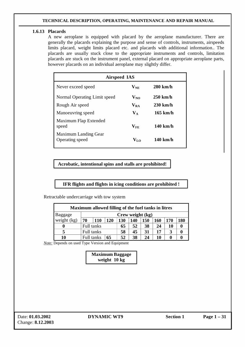
1.6.13 Placards A new aeroplane is equipped with placard by the aeroplane manufacturer. There are generally the placards explaining the purpose and sense of controls, instruments, airspeeds limits placard, weight limits placard etc. and placards with additional information.. The placards are usually stuck close to the appropriate instruments and controls, limitation placards are stuck on the instrument panel, external placard on appropriate aeroplane parts, however placards on an individual aeroplane may slightly differ.
Airspeed IAS
Never exceed speed VNE 280 km/h
Normal Operating Limit speed VNO 250 km/h
Rough Air speed VRA 230 km/h
Manoeuvring speed VA 165 km/h
Maximum Flap Extended speed VFE 140 km/h
Maximum Landing Gear Operating speed VLO 140 km/h
Acrobatic, intentional spins and stalls are prohibited!
IFR flights and flights in icing conditions are prohibited !
Retractable undercarriage with tow system
Maximum allowed filling of the fuel tanks in litres Crew weight (kg) Baggage
weight (kg) 70 110 120 130 140 150 160 170 180 0 Full tanks 65 52 38 24 10 0 5 Full tanks 58 45 31 17 3 0 10 Full tanks 65 52 38 24 10 0 0
Note: Depends on used Type Version and Equipment
Maximum Baggage weight 10 kg
Date: 01.03.2002 DYNAMIC WT9 Section 1 Page 1 – 31 Change: 8.12.2003
TECHNICAL DESCRIPTION, OPERATING, MAINTENANCE AND REPAIR MANUAL
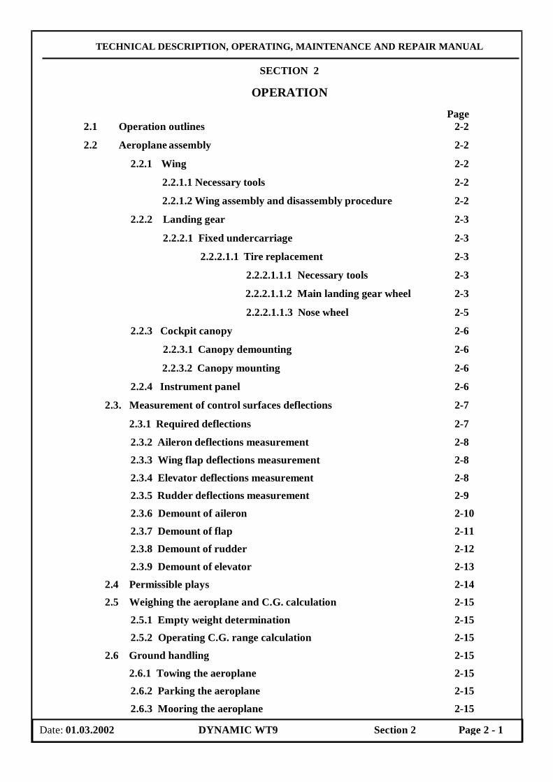
SECTION 2
OPERATION
Page 2.1 Operation outlines 2-2
2.2 Aeroplane assembly 2-2
2.2.1 Wing 2-2
2.2.1.1 Necessary tools 2-2
2.2.1.2 Wing assembly and disassembly procedure 2-2
2.2.2 Landing gear 2-3
2.2.2.1 Fixed undercarriage 2-3
2.2.2.1.1 Tire replacement 2-3
2.2.2.1.1.1 Necessary tools 2-3
2.2.2.1.1.2 Main landing gear wheel 2-3
2.2.2.1.1.3 Nose wheel 2-5
2.2.3 Cockpit canopy 2-6
2.2.3.1 Canopy demounting 2-6
2.2.3.2 Canopy mounting 2-6
2.2.4 Instrument panel 2-6
2.3. Measurement of control surfaces deflections 2-7
2.3.1 Required deflections 2-7
2.3.2 Aileron deflections measurement 2-8
2.3.3 Wing flap deflections measurement 2-8
2.3.4 Elevator deflections measurement 2-8 2.3.5 Rudder deflections measurement 2-9
2.3.6 Demount of aileron 2-10
2.3.7 Demount of flap 2-11 2.3.8 Demount of rudder 2-12
2.3.9 Demount of elevator 2-13
2.4 Permissible plays 2-14 2.5 Weighing the aeroplane and C.G. calculation 2-15
2.5.1 Empty weight determination 2-15 2.5.2 Operating C.G. range calculation 2-15
2.6 Ground handling 2-15
2.6.1 Towing the aeroplane 2-15 2.6.2 Parking the aeroplane 2-15
2.6.3 Mooring the aeroplane 2-15
Date: 01.03.2002 DYNAMIC WT9 Section 2 Page 2 - 1
TECHNICAL DESCRIPTION, OPERATING, MAINTENANCE AND REPAIR MANUAL
2.6.4 Jacking the aeroplane 2-15 2.7 Road transport 2-16
2.1 Operation outlines
During operation and maintenance of DYNAMIC WT 9 aeroplane it is very important to keep instructions stated in the aeroplane accompanying documentation:
- Technical Description, Operating, Maintenance and Repair Manual for Ultralight aeroplane DYNAMIC WT 9
- Flight Manual for Ultralight aeroplane DYNAMIC WT 9
- Operator’s Manual for all versions of ROTAX 912 engine - Operator’s Manual for electric adjustable aircraft propeller SR 2000. - Additional documents supplied with an aeroplane instruments or equipment.
The airworthiness and operational readiness of the aeroplane depend upon careful adherence to the recommended procedures and regulations. Climate, aerodrome conditions, dustiness, manner of hangaring and other factors, such as corrosive effects in industrial or seaside areas, should be considered by an aeroplane operator. The procedures given in this Manual suit coverage operational conditions, and more harsh environments may require more frequent scheduled maintenance.
2.2 Aeroplane assembly 2.2.1 Wing
There is described the rigging procedure for the right wing. The procedure for the left wing is analogous.
2.2.1.1 Necessary tools
( A screwdriver
( An adhesive tape
( Lubricant to preserve the wing suspensions
2.2.1.2 Wing assembly and disassembly procedure 1. Thoroughly clean and lubricate all the wing suspensions before wing assembly. 2. All pins easily lubricate. 3. Fit the spar end of the right wing into the spar end ( fork ) of the wing central panel and
push the wing along longitudinal axis so that a connection slot between the wing central panel and the wing root is approx. 100 mm. The person holding the wing tip lower it down at a thorax level.
4. Connect the hoses from the Pitot-static tube ( connect the position lights wires connector, if lights installed ). They must not be twisted.
5. Full push the wing into the wing central panel. Place fixation pins for connection of the wing spar end with the wing central panel . The outer pin is inserted through the room for main legs of the retractable undercarriage ( at model SPEED ) or through the access hole on the lower wing surface ( at model CLUB and TOW ). The inner pin is inserted through the hole in the cockpit below pilot seat ( slightly lift and lower the wing tip to make easy the pin insertion ). Secure both pins with splint pins.
Date: 01.03.2002 DYNAMIC WT9 Section 2 Page 2 - 2
TECHNICAL DESCRIPTION, OPERATING, MAINTENANCE AND REPAIR MANUAL
6. Insert auxiliary pin through the suspension at the auxiliary girder of the wing central panel and secure all the pins into special forks with split pin.
7. Insert the pin of the extended wing flap hinge into the suspension of the wing central panel and secure the connection.
8. A short flap rod joints with a flap arm, secure joint pin with a cotter pin. During this procedure the flap control lever in the cockpit shall be set to the rearmost position and the flap shall be deflect to maximum down position.
9. Joint the aileron control rod and secure the connection ( a castle nut secure with a cotter pin ).
10. After check the securing of the connection the connection slot between wing and the wing central panel should be glued with adhesive tape.
NOTE
Take care of pitotstatic tube when handling the right wing. Use the opposite sequence for wing disassembly procedure.
2.2.2 Landing gear
2.2.2.1 Fixed undercarriage 2.2.2.1.1 Tire replacement
2.2.2.1.1.1 Necessary tools - A screwdriver - A rubber hammer - A combination pliers - A spanner to tighten and loose M13 attaching nuts of the wheel fairing. - A spanner to tighten and loose M10 attaching nuts of the bolts which connecting left
and right part of a rim - A spanner to tighten and loose M22 main wheel axle nut
2.2.2.1.1.2 Main landing gear wheel
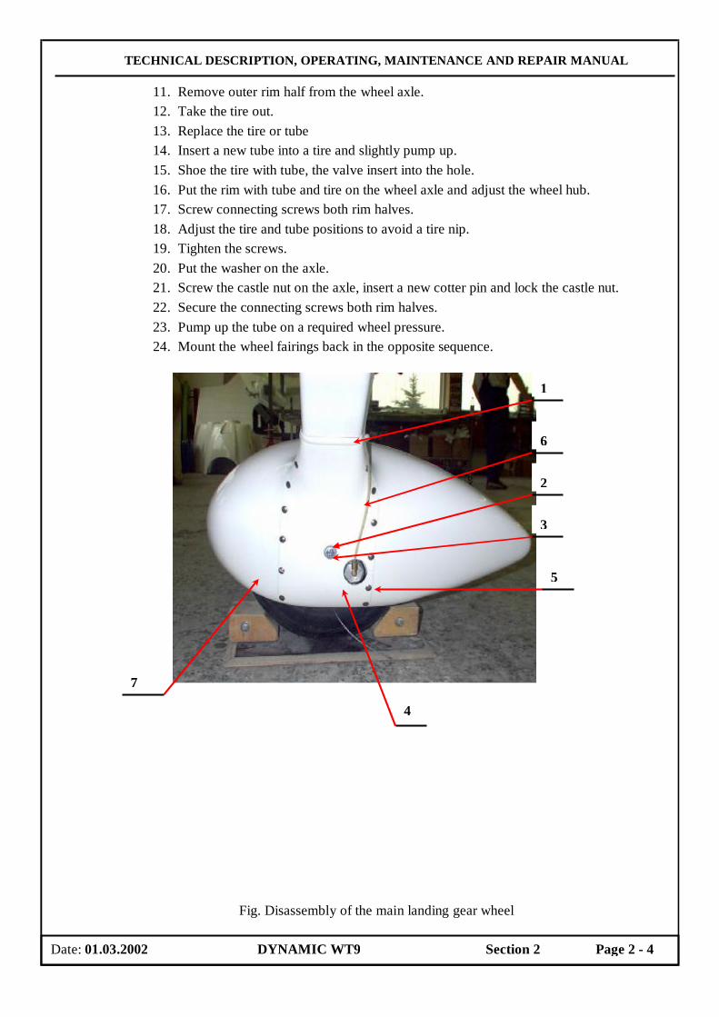
At a tire replacement of the main landing gear wheel proceed in accordance with following procedure: 1. Disconnect the contact stripes (1), which attach a brake hose on the main landing
gear leg. 2. Straighten bend small tabs (2) under screws of the wheel fairing. 3. Unscrew the screws (3) of the wheel fairing . 4. Unscrew the screws (5) of the brake hydraulic cylinder cover (4). 5. Advance a cover so that brake hose (6) passes through a slice of the cover. 6. Move up and demount the cover (7). 7. Remove the cotter pin of the main wheel axle castle nuts and unscrew the castle nut. 8. Remove the washer from the wheel axle. 9. Deflate a wheel tube.
10. Unscrew and remove the screws which joint together both rim halves.
Date: 01.03.2002 DYNAMIC WT9 Section 2 Page 2 - 3
TECHNICAL DESCRIPTION, OPERATING, MAINTENANCE AND REPAIR MANUAL
11. Remove outer rim half from the wheel axle. 12. Take the tire out. 13. Replace the tire or tube 14. Insert a new tube into a tire and slightly pump up. 15. Shoe the tire with tube, the valve insert into the hole. 16. Put the rim with tube and tire on the wheel axle and adjust the wheel hub. 17. Screw connecting screws both rim halves. 18. Adjust the tire and tube positions to avoid a tire nip. 19. Tighten the screws. 20. Put the washer on the axle. 21. Screw the castle nut on the axle, insert a new cotter pin and lock the castle nut. 22. Secure the connecting screws both rim halves. 23. Pump up the tube on a required wheel pressure. 24. Mount the wheel fairings back in the opposite sequence.
Fig. Disassembly of the main landing gear wheel
Date: 01.03.2002 DYNAMIC WT9 Section 2 Page 2 - 4
1
6
2
3
5
4
7

TECHNICAL DESCRIPTION, OPERATING, MAINTENANCE AND REPAIR MANUAL
2.2.2.1.1.3 Nose wheel At a tire replacement of the nose landing gear wheel proceed in accordance with following procedure:
1. Dismantle a nose wheel fairing ( if installed ) 2. Remove a cotter pin securing a castle nut on a wheel axle. 3. Release and unscrew the castle nut on the wheel axle. 4. Remove a washer from the wheel axle. 5. Lift the nose of the aeroplane
a) Push the rear of the fuselage down and support the aeroplane under the nose wheel leg – fuselage attachment or
b) Sling a suitable load at the rear part of fuselage near the fin ( bags with a load ) to lift the nose wheel above ground.
6. Knock the wheel axle out of the wheel fork by means of a hammer and suitable brass round.
7. Remove the nose wheel. 8. Deflate a wheel tire. 9. Release and unscrew 3 self-locking nuts from the bolts which connecting left and
right part of a rim. 10. Remove 3 bolts. 11. Take apart the rim halves. 12. Take the tire out. 13. Replace the tire or tube. 14. Insert a new tube into a tire and slightly pump up. 15. Set a half of a rim ( with valve ) on the wheel axle. 16. Shoe the tire with tube, the valve insert into the hole. 17. Set the other half of the rim on the wheel axle. 18. Adjust the tire and tube positions to avoid a tire nip. 19. Attach both half of the rim with 3 bolts. 20. Put the washers on the bolts. 21. Screw and tighten self-locking nuts. 22. Draw the wheel axle out of the rim. 23. Pump the wheel on a required pressure. 24. Insert the wheel in the fork. 25. Set and hammer the wheel axle into the fork. 26. Put the washer on the wheel axle. 27. Screw the castle nut on the axle. 28. Insert a new cotter pin and lock the castle nut. 29. Lift the aeroplane down the supports ( remove a support of the aeroplane under the
nose wheel leg or the bags from the tail ) 30. Mount the wheel fairings back ( if installed ).
CAUTION Usage of new self-locking nuts is highly recommended.
Date: 01.03.2002 DYNAMIC WT9 Section 2 Page 2 - 5

TECHNICAL DESCRIPTION, OPERATING, MAINTENANCE AND REPAIR MANUAL
2.2.3 Cockpit canopy
2.2.3.1 Canopy demounting Apply the following procedure to demount the cockpit canopy: 1. Open canopy should be supported. 2. Dismantle both gas struts. The securing shim sweep into a open position for the
releasing of the strut joint pin. 3. Unscrew self-locking nuts of the front canopy hinges which are located in the cockpit. 4. Remove the canopy attachment screws. 5. Carefully remove the canopy.
WARNING Be carefully at canopy handling on the ground of a possibility a
damage of the Perspex canopy.
2.2.3.2 Canopy mounting
The mounting procedure is opposite to the demounting one and does not require additional explanation.
2.2.4 Instrument panel The instrument panel is separated into two parts. The upper part of the instrument panel contains the flight instruments and powerplant instrument and lower part contains the powerplant controls. A sheet cover over the instrument panel removes after the releasing of the connecting screws when install or de-install the instruments. The flight and navigation instruments are mounted as an option of the customer ( but with respect to the weight limitation and C.G. of the ultra light aircraft ). Follow the instructions of an instrument manufacturer.
Date: 01.03.2002 DYNAMIC WT9 Section 2 Page 2 - 6

TECHNICAL DESCRIPTION, OPERATING, MAINTENANCE AND REPAIR MANUAL
2.3. Control surfaces 2.3.1 Required deflections
Control surfaces deflections are specified in a Control Surface Deflections Record ( see Appendices of this Manual and in the following figure:
Ailerons: Flaps: Elevator:
Rudder:
A protractor with deflecting hand is used by aeroplane manufacturer to measure deflections, the protractor is attached to a trailing edge of the control surface. There are also described procedure in the following text ( a measurement of the distance of the deflected control surface trailing edges from a neutral position ). Specified distances are present in the figure.
Date: 01.03.2002 DYNAMIC WT9 Section 2 Page 2 - 7

TECHNICAL DESCRIPTION, OPERATING, MAINTENANCE AND REPAIR MANUAL
2.3.2 Aileron deflections measurement
Measurement procedure:
1. Attach a protractor with deflection hand at upper aileron trailing edge.
2. Set the aileron in neutral position.
3. Zero the protractor – starting position for measurement.
4. Deflect the aileron fully down/up and read the deflections.
5. Compare, if measured deflections correspond with those ones specified in Control Surfaces Deflections Record.
6. If not – adjust aileron deflections according to the par 3.11.1.
If there is not a protractor at disposal, can be applied a measurement procedure of the distance of the deflected control surface trailing edges from a neutral position according to the figure.
2.3.3 Wing flap deflections measurement The wing flaps can be set in 4 positions :
- Retracted ( deflection 0° )
- Take-off (deflection 15° )
- Intermediate (deflection 24° )
- Landing ( maximum deflection 35° )
The flap control lever located on the pedestal between the seats. Set flap position is locked by the deflection of the flap control lever into the appropriate recesses A protractor measurement procedure is similar to the aileron deflection measurement procedure. If there is not a protractor at disposal, the following procedure can be applied:
1. Insert a hard drawing paper in a space between a fuselage and flap and hold the drawing paper to the wing central panel upper surface by means of the adhesive tape.
2. Trace the trailing edge of the retracted flap.
3. Extend the flap to a required position and trace the trailing edge of the set flap again.
4. Remove the drawing paper and directly measure the distances from the “Retracted“ position by means of a ruler.
5. Compare, if measured deflections correspond with those ones specified in Control Surfaces Deflections Record.
6. If not – adjust flap deflections according to the par 3.11.4 The deflection of left flap against right flap may be adjusted on the last short rod, which is attached to a flap lever.
2.3.4 Elevator deflections measurement A protractor measurement procedure is similar to the aileron deflection measurement procedure. If there is not a protractor at disposal, the following procedure can be applied:
1. Attach the drawing papers to the rudder side surfaces by means of the adhesive tape.
Date: 01.03.2002 DYNAMIC WT9 Section 2 Page 2 - 8
TECHNICAL DESCRIPTION, OPERATING, MAINTENANCE AND REPAIR MANUAL
2. Mark the neutral position of the elevator trailing edge.
3. Fully pull and push the control stick to deflect the elevator and mark the positions of deflected elevator trailing edge.
4. Measure the distances between marks at a half of the elevator on the hard drawing paper by means of a ruler.
5. Compare, if measured deflections correspond with those ones specified in Control Surfaces Deflections Record.
7. If not – adjust elevator deflections with adjustable end of rod according to the par 3.11.2 2.3.5 Rudder deflections measurement
Measurement procedure: 1. Insert a hard drawing paper in a space between a rudder and a fuselage aft part and hold
the drawing paper to the fuselage bottom below rudder by means of the adhesive tape. 2. Mark the neutral position of the lower rudder trailing edge on a hard drawing paper. 3. Fully deflect the rudder and mark the position of a deflected lower rudder trailing edge
on a hard drawing paper. 4. Measure by means of a ruler distance between the mark on a hard drawing paper. 5. Compare, if measured deflections correspond with those one in Control Surfaces
Deflections Record. Record real values into the Record.
Date: 01.03.2002 DYNAMIC WT9 Section 2 Page 2 - 9

TECHNICAL DESCRIPTION, OPERATING, MAINTENANCE AND REPAIR MANUAL
2.3.6 Demount of ailerons
1. Remove the transparent cover from inspection openinng on the wing bottom side. Cut he silicon sealing off with sharp knigfe and remove tho cover.
2. Release the self locking nuts M6 and disconnect the short aileron drive rod from the angle
arm. 3. Remove the sealing MILLAR foil; aileron-wing. 4. Disconnect the bolt LN M6 x 26 on ailerong hing, remove the cotter pin, and castle nut M6,
than remove the washer and bolt screw. 5. Remove the securing tensile hollow pin of aileron hinge (use the podger ∅ 2 mm). Follow
the same procedure on seckond aileron hinge. 6. Remove the aileron hinge pins. 7. Carefully slide out the aileron together with short aileron drive rod. 8. If required disconnect the short rod from the aileron.
The mount of ailerons is carried out in oposit order.
Bolt LN M6 x 26
Podger ∅ 2mm
Date: 01.03.2002 DYNAMIC WT9 Section 2 Page 2 - 10
TECHNICAL DESCRIPTION, OPERATING, MAINTENANCE AND REPAIR MANUAL
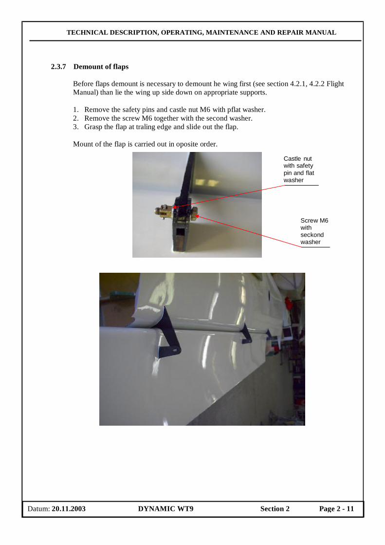
2.3.7 Demount of flaps
Before flaps demount is necessary to demount he wing first (see section 4.2.1, 4.2.2 Flight Manual) than lie the wing up side down on appropriate supports. 1. Remove the safety pins and castle nut M6 with pflat washer. 2. Remove the screw M6 together with the second washer. 3. Grasp the flap at traling edge and slide out the flap. Mount of the flap is carried out in oposite order.
Datum: 20.11.2003 DYNAMIC WT9 Section 2 Page 2 - 11
Castle nut with safety pin and flat washer
Screw M6 with seckond washer
TECHNICAL DESCRIPTION, OPERATING, MAINTENANCE AND REPAIR MANUAL
Mount openning
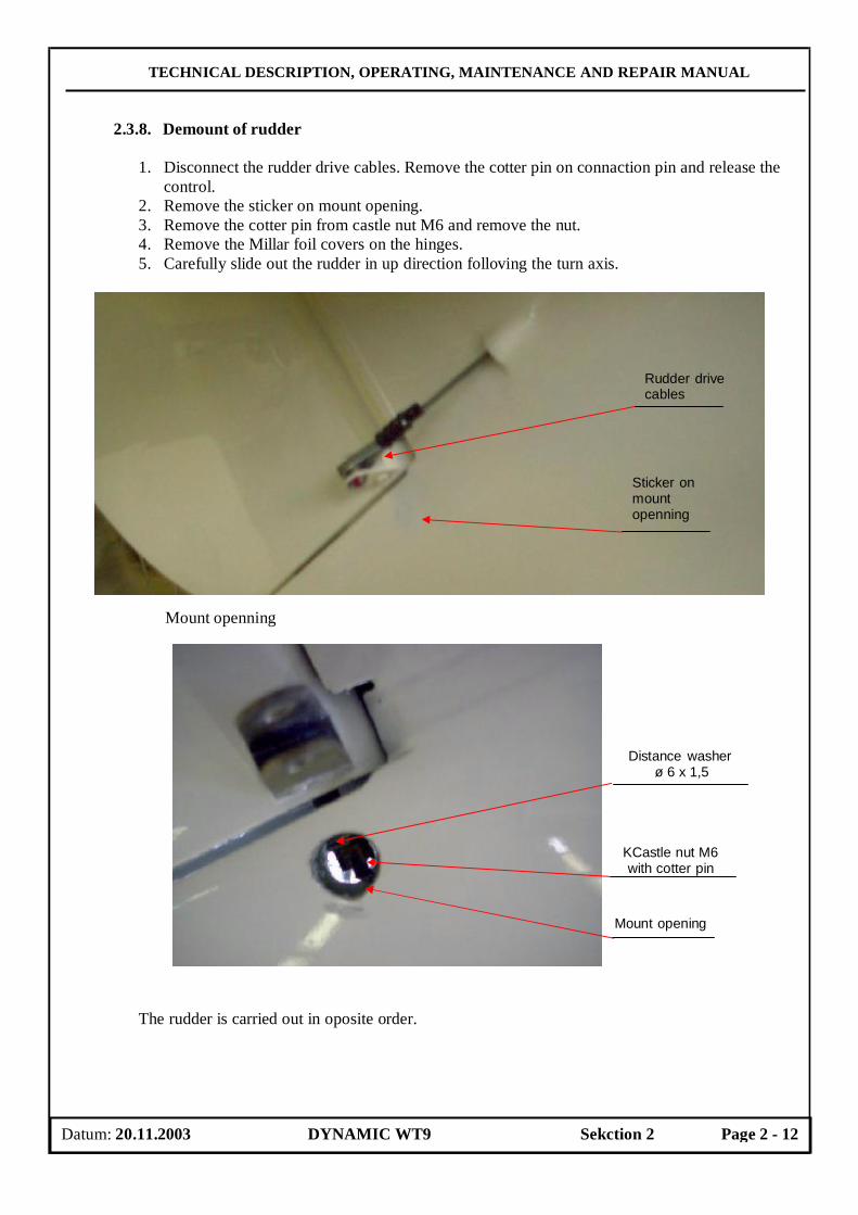
2.3.8. Demount of rudder
1. Disconnect the rudder drive cables. Remove the cotter pin on connaction pin and release the control.
2. Remove the sticker on mount opening. 3. Remove the cotter pin from castle nut M6 and remove the nut. 4. Remove the Millar foil covers on the hinges. 5. Carefully slide out the rudder in up direction folloving the turn axis.
The rudder is carried out in oposite order.
Datum: 20.11.2003 DYNAMIC WT9 Sekction 2 Page 2 - 12
Distance washer ø 6 x 1,5
KCastle nut M6 with cotter pin
Mount opening
Rudder drive cables
Sticker on mount openning

TECHNICAL DESCRIPTION, OPERATING, MAINTENANCE AND REPAIR MANUAL
2.3.9 Demount of elevator
1. Demount the rudder; see instructions in section 2.3.8 of this manual. 2. Remove the self locking nuts M6 (3 x) and washers, connecting the control surface to drive. 3. Carefully slide out the elevator.
Mount of elevator is carried out in oposite order.
Datum: 20.11.2003 DYNAMIC WT9 Section 2 Page 2 - 13
Elevator connection to drive
with 3 x nut M6
Elevator drive

TECHNICAL DESCRIPTION, OPERATING, MAINTENANCE AND REPAIR MANUAL
2.4 Permissible plays
In the following table are shown the permissible plays for most important parts of the aeroplane. These values should be not exceeded in operation.
It is expected that an operator will take steps if finds excessive plays of any other part not listed below.
System Procedure to find a play Procedure to
remedy a play Max. productplay
Max. operation play
Ailerons control system
Block ailerons up to the wing and move the control stick to the left and right to find possible plays
Check condition of bearings and replace if need be
2 mm
5 mm
Elevator control system
Block elevator up to the stabilizer, pull and push the control stick to find possible plays
Check condition of bearings and replace if need be
2 mm
5 mm
Flaps control system
Extend the flaps and then handle the flap trailing edge near the flap root, move the trailing edge up/downward to find possible plays
Check condition of a an arrest of the flap control lever in the cockpit, check condition of sliding bearings stowage and replace the worn-out joint bearings on the rod ends
2 mm
5 mm
Ruder control
The system is prestressed by means of a cylinder springs ( therefore it had not has a possible plays ). Rudder hinges ( stowage ) check by the moving of the rudder
Change bearing bushes.
Rudder hinges
1 mm
2 mm
Wing-Fuselage attachment
Move a wing tip to find possible plays in wing suspensions.
Check wing suspensions, replace pins
0 mm 2 mm at wing tip
Nose wheel Push the rear part of the fuselage down (use a weight) to lift the nose wheel, then move the wheel forward-rearward to find possible plays.
Remove the wheel, remove the rim and tire and replace the bearings bushes and bearings.
1 mm
3 mm
Main landing gear Jack the aeroplane or lift the wing tip to lift a main leg, then move the wheel forward-rearward to find possible plays in bearings or leg attachment.
Check the leg attachment, wheels attachment, replace the bearings, if necessary.
1 mm
3 mm
Date: 01.03.2002 DYNAMIC WT9 Section 2 Page 2 - 14
TECHNICAL DESCRIPTION, OPERATING, MAINTENANCE AND REPAIR MANUAL
2.5 Weighing the aeroplane and C.G. calculation
There is necessary to abide with permitted maximum take-off weight and C.G. range for any configuration of crew, fuel and baggage according to the Flight Manual. The removal or addition of equipment results in changes to the centre of gravity and empty weight of the aeroplane, and the permissible useful load is affected accordingly. In that case new weighing is necessary to determine new empty weight and centre of gravity position of empty aeroplane. New empty weight and C.G. position should be recorded in Flight Manual, Section 6., Weight and Balance Record / Permitted Payload Range and new permitted crew weight for appropriate fuelling and baggage weight must be computed and recorded, also. Then in the cockpit stuck placard “Load Limits” should be up-dated.
2.5.1 Empty weight determination
The empty weight of an aeroplane includes all operating equipment that has a fixed location and is actually installed in the aeroplane. It includes the weight of the painted aeroplane, accumulator, standard and optional equipment, full engine coolant, hydraulic fluid ( for retractable undercarriage ), brake fluid, oil. The aeroplane is weighing without crew, fuel and baggage. The following weighing procedure is recommended: 1. Remove excessive dirt, grease, moisture from aeroplane before weighing. 2. Weight the aeroplane inside a closed building to prevent error in scale due to wind. 3. Place the scales, properly calibrate zero. 4. Place the aeroplane on the scales ( use board to run on the scales or lift the aeroplane –
see aeroplane jacking ). 5. The aeroplane position for weighting has to be parallel with the horizontal plane which
passes through the side edge of the cockpit ( check by means of a spirit-level ). 6. Weight the aeroplane and record read values in Weight and Balance Record ( make a
copy of standard Record included in section 5 Appendices ). 7. Compute the weight and C.G. position according to the formulae given in the Record. 8. Compare, if computed C.G. position with those one in the Weight and Balance Record. 9. Up-date the placard “ Load Limits “ ( make a new one ) stuck in the cockpit.
2.5.2 Operating C.G. range calculation
Operating C.G. position calculation procedure is evident from the Record. The reference point ( datum point = DP ) is leading edge of wing root section ( Note: Moment from the nose wheel substitutes as a negative value ). There are the arms of the items to the DP ( fuel, crew, baggage ) in the Record for a purpose of Operating C.G. position calculation procedure. In case, that calculated C.G. position is out of C.G. range limits, is necessary change a position of any items or locate an additional ballast ( beware of maximum allowed take-off weight excess ).
Date: 01.03.2002 DYNAMIC WT9 Section 2 Page 2 - 15

TECHNICAL DESCRIPTION, OPERATING, MAINTENANCE AND REPAIR MANUAL
2.6 Ground handling 2.6.1 Towing the aeroplane
The aeroplane can be displaced by means of towing the aeroplane at a short distance by holding the blade. Handle the propeller by holding the blade root – never blade tip. For a direction motion change push rear part of a fuselage close before a fin down to lift the nose wheel, than turn the aeroplane into a required direction.
CAUTION
Avoid excessive pressure at the aeroplane control surfaces and the wing tips. The perpendicular pressure on the surface of the airframe sandwich shell thin skin layers can produce a creation of a prints. These prints can weaken a sandwich shell. During
the aeroplane towing handle the propeller by holding the blade root – never blade tip.
2.6.2 Parking the aeroplane
There is advisable to park the aeroplane inside a hangar or eventually inside other proof space. During the aeroplane parking can be used a parking brake.
CAUTION In case of a parking outside a hangar and at long term parking
to cover cockpit canopy by means of a suitable cloth dust-cover, due to preclusion of the sun effect. The sunbeams
together with the optical action of the cockpit canopy may be the source of the spot heating, which can create damage of the
cockpit area and the upholstery.
2.6.3 Mooring the aeroplane The aeroplane is usually moored in case of parking outside a hangar or if need be. By this reason the aeroplane is equipped with mooring eyes (GL) located ant wing lower surface. The aeroplane moors to the ground by means of a mooring rope passed through the mooring eyes. There is also necessary to moor the nose wheel landing gear, to shut all venting holes ( a side sliding window ), to block the control stick up e.g. by means of safety harness, to close and to cover cockpit canopy.
2.6.4 Jacking the aeroplane
Since the empty weight of this aeroplane is relatively low there is easy to lift the aeroplane without a special equipment. The aeroplane may be lifted by handling the following parts: 1. Push down the rear part of fuselage ( handle the fuselage before the fin ) to lift the nose
wheel and then support the fuselage under the firewall by means of a suitable support. 2. For a complex check of the retractable undercarriage lift the aeroplane with help of the
holders at places assigned for this purpose. These supported points (SP) are located at the wing central panel lower surface behind the auxiliary spar and at a firewall ( see figure ).
Date: 01.03.2002 DYNAMIC WT9 Section 2 Page 2 - 16
TECHNICAL DESCRIPTION, OPERATING, MAINTENANCE AND REPAIR MANUAL
If the aeroplane is supported at these points, than may be performed a operation test of the retractable undercarriage ( retracting and releasing ) with one person in the cockpit.
2.7 Road transport The aeroplane may be transported after its loading at a suitable car trailer or a lorry. Disassembly the wing according to the procedure in the par. 2.2.1.2.
The airframe surfaces should be protected by means of a light plastic foil or cloth cover against the dust. The check holes of the engine, the fuel tanks and the pitot static system should be enclosed before the transportation, due to ability of the penetration of the strange objects ( insect, birds ) by means of an adhesive tape. The landing gear latches by means of a suitable blocks. There is also necessary to moor the nose wheel landing gear to the floor of the lorry. The dismantled wings should be fastened down to ensure these parts against a possible damage ( the wing leading edges ). The control stick blocks up by means of the safety harness. The side sliding window shuts and a cockpit canopy closes and covers. The propeller blades covers by means of a special covers.
Date: 01.03.2002 DYNAMIC WT9 Section 2 Page 2 - 17
TECHNICAL DESCRIPTION, OPERATING, MAINTENANCE AND REPAIR MANUAL
SECTION 3
MAINTENANCE
Page 3.1 Overall maintenance survey 3-2
3.2 Daily inspection 3-2
3.3 Pre-flight inspection 3-2
3.4 Inter-flight inspection 3-3
3.5 Post-flight inspection 3-3
3.6 Periodical inspections 3-3
3.6.1 Periodical inspections intervals 3-3
3.6.2 Periodical inspections Sign off sheets 3-3
3.6.3 Periodical inspections – events 3-4
3.6.4 List of periodical inspections of ROTAX 912UL/ULS engine 3-12
3.7 Operating media 3-13
3.7.1 Engine oil 3-13
3.7.2 Coolant 3-14
3.7.3 Brake fluid 3-14
3.7.5 Fuel 3-14
3.7.5.1 Fuelling 3-15
3.8 Lubrication 3-15
3.8.1 Lubrication fundamentals 3-15
3.8.2 Recommended lubricants 3-15
3.8.3 Lubricating points 3-16
3.9 Mechanisms adjustments 3-17
3.9.1 Torque moments 3-17
3.9.2 Necessary maintenance tools 3-18
3.9.3 Inspection holes 3-18
3.10 Brake system 3-18
3.10.1 Brake plate replacement 3-18
3.10.2 Venting 3-19
3.10.3 Brakes adjustment 3-20
3.11 Control surfaces deflections setting 3-20
3.11.1 Aileron deflections adjustment 3-20
Date: 01.03.2002 DYNAMIC WT9 Section 3 Page 3 - 1
TECHNICAL DESCRIPTION, OPERATING, MAINTENANCE AND REPAIR MANUAL
3.11.2 Elevator deflections adjustment 3-20
3.11.3 Trimming deflections adjustment 3-20
3.11.4 Flap deflections adjustment 3-20
3.11.5 Rudder deflections adjustment 3-21
3.12 Nose wheel leg flexible polyurethane roller replacement 3-21
3.12.1 Fixed undercarriage 3-21
3.13 Tire inflating 3-22
3.14 Winter operation 3-21
3.14.1 General 3-21
3.14.2 Preparing the aeroplane for winter operation 3-21
3.14.3 Operation 3-23
3.1 Overall maintenance survey The aeroplane maintenance is a care and repairs of an aeroplane to save its airworthiness. There are performed periodical events ( periodical and pre-flight inspections ) and irregular events e.g. a repair of a damage.
3.2 Daily inspection The daily inspection must be performed before every flight day of the ultralight aeroplane. A method of the daily inspection execution is the object of a pilot training. The scope of this inspection is specified in the Flight Manual and in the additional documents supplied with an aeroplane instruments or equipment. Special attention must be devoted to the parts, which are affected by the high vibrations and high temperatures from a powerplant.
These parts are especially: - a propeller attachment
- an exhaust system ( a muffler )
- an engine attachment
- a wiring, especially an ignition system
- a lubrication system, a cooling system and a fuel system
3.3 Pre-flight inspection
This inspection is shorter than a daily inspection whereupon the pre-flight inspection should be performed before each flight. The Flight Manual presents more information about a pre-flight inspection. If any problems are found they must be corrected before flying.
Date: 01.03.2002 DYNAMIC WT9 Section 3 Page 3 - 2
TECHNICAL DESCRIPTION, OPERATING, MAINTENANCE AND REPAIR MANUAL
3.4 Inter-flight inspection
Inter-flight inspection is a visual check of aeroplane for deformations, surface damages, fuel and oil system leaks, propeller damages, released locks, covers and cowlings etc. The found damages and failures should be repaired immediately if aeroplane airworthiness is affected or when impossible the aeroplane should be put out of operation.
3.5 Post-flight inspection
Post-flight inspection is performed in the end of each flight day; the post-flight inspection events are the same as the preflight ones. Failures, damages and malfunctions should be recorded and repaired immediately, if possible by a qualified staff. It is useful to clean and/or wash the aeroplane surface. Check also fuel and oil consumption if are in normal range. Lastly record hours flown and other data in appropriate documentation of an aeroplane ( engine, propeller ).
3.6 Periodical inspections 3.6.1 Periodical inspections intervals
periods of overall checks and contingent maintenance depends on the condition of the operation and on overall condition of the aeroplane. The producer recommends to accomplish maintenance checks and periodic inspections in the following periods, at least:
1) after the first 25 ± 2 flight hours
2) after every 50 ± 3 flight hours
3) after every 100 ± 5 flight hours
Refer to the Operator’s Manual for all versions of ROTAX 912 engine and the Operator’s Manual for electric adjustable aircraft propeller SR 2000.
3.6.2 Periodical inspections Sign off sheets
The following Periodical inspections Sign off sheets are intended for copying and serve as the Maintenance Record. There is also recommended to register small repairs, damages and their remedy or replacement of parts. Some parts of the aeroplane ( engine, landing gear and propeller etc. ) may have special time limits – refer to appropriate manuals.
Date: 01.03.2002 DYNAMIC WT9 Section 3 Page 3 - 3
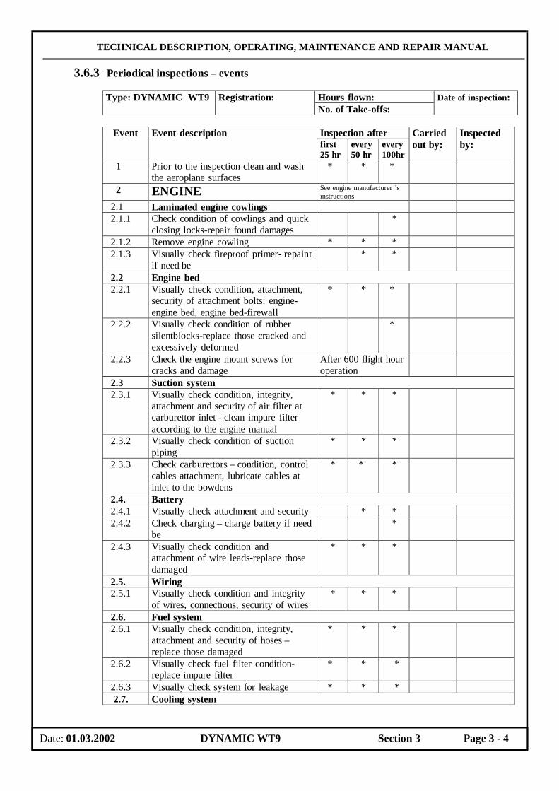
TECHNICAL DESCRIPTION, OPERATING, MAINTENANCE AND REPAIR MANUAL
3.6.3 Periodical inspections – events
Inspection after Event Event description first 25 hr
every 50 hr
every 100hr
Carried out by:
Inspected by:
1 Prior to the inspection clean and wash the aeroplane surfaces
* * *
2 ENGINE See engine manufacturer ´s instructions
2.1 Laminated engine cowlings 2.1.1 Check condition of cowlings and quick
closing locks-repair found damages *
2.1.2 Remove engine cowling * * * 2.1.3 Visually check fireproof primer- repaint
if need be * *
2.2 Engine bed 2.2.1 Visually check condition, attachment,
security of attachment bolts: engine-engine bed, engine bed-firewall
* * *
2.2.2 Visually check condition of rubber silentblocks-replace those cracked and excessively deformed
*
2.2.3 Check the engine mount screws for cracks and damage
After 600 flight hour operation
2.3 Suction system 2.3.1 Visually check condition, integrity,
attachment and security of air filter at carburettor inlet - clean impure filter according to the engine manual
* * *
2.3.2 Visually check condition of suction piping
* * *
2.3.3 Check carburettors – condition, control cables attachment, lubricate cables at inlet to the bowdens
* * *
2.4. Battery 2.4.1 Visually check attachment and security * * 2.4.2 Check charging – charge battery if need
be *
2.4.3 Visually check condition and attachment of wire leads-replace those damaged
* * *
2.5. Wiring 2.5.1 Visually check condition and integrity
of wires, connections, security of wires * * *
2.6. Fuel system 2.6.1 Visually check condition, integrity,
attachment and security of hoses – replace those damaged
* * *
2.6.2 Visually check fuel filter condition-replace impure filter
* * *
2.6.3 Visually check system for leakage * * * 2.7. Cooling system
Hours flown: Type: DYNAMIC WT9 Registration: No. of Take-offs:
Date of inspection:
Date: 01.03.2002 DYNAMIC WT9 Section 3 Page 3 - 4
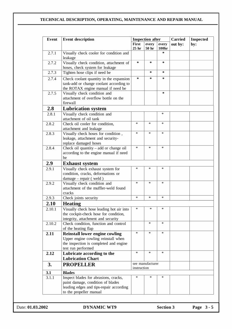
TECHNICAL DESCRIPTION, OPERATING, MAINTENANCE AND REPAIR MANUAL
Inspection after Event Event description First 25 hr
every 50 hr
every 100hr
Carried out by:
Inspected by:
2.7.1 Visually check cooler for condition and leakage
*
2.7.2 Visually check condition, attachment of hoses, check system for leakage
* * *
2.7.3 Tighten hose clips if need be * * 2.7.4 Check coolant quantity in the expansion
tank-add or change coolant according to the ROTAX engine manual if need be
* * *
2.7.5 Visually check condition and attachment of overflow bottle on the firewall
*
2.8 Lubrication system 2.8.1 Visually check condition and
attachment of oil tank *
2.8.2 Check oil cooler for condition, attachment and leakage
* * *
2.8.3 Visually check hoses for condition , leakage, attachment and security-replace damaged hoses
* * *
2.8.4 Check oil quantity – add or change oil according to the engine manual if need be
* * *
2.9 Exhaust system 2.9.1 Visually check exhaust system for
condition, cracks, deformations or damage – repair ( weld )
* * *
2.9.2 Visually check condition and attachment of the muffler-weld found cracks
* * *
2.9.3 Check joints security * * * 2.10 Heating 2.10.1 Visually check hose leading hot air into
the cockpit-check hose for condition, integrity, attachment and security
* * *
2.10.2 Check condition, function and control of the heating flap
* *
2.11 Reinstall lower engine cowling Upper engine cowling reinstall when the inspection is completed and engine test run performed
* * *
2.12 Lubricate according to the Lubrication Chart
* * *
3. PROPELLER see manufacturer instruction
3.1 Blades 3.1.1 Inspect blades for abrasions, cracks,
paint damage, condition of blades leading edges and tips-repair according to the propeller manual
* * *
Date: 01.03.2002 DYNAMIC WT9 Section 3 Page 3 - 5
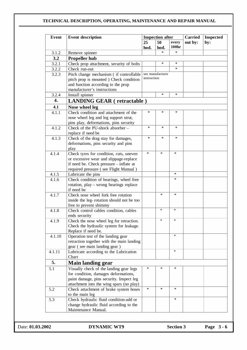
TECHNICAL DESCRIPTION, OPERATING, MAINTENANCE AND REPAIR MANUAL
Inspection after Event Event description 25 hod.
50 hod.
every 100hr
Carried out by:
Inspected by:
3.1.2 Remove spinner * * 3.2 Propeller hub
3.2.1 Check prop attachment, security of bolts * * 3.2.2 Check run-out * 3.2.3 Pitch change mechanism ( if controllable
pitch prop is mounted ) Check condition and function according to the prop manufacturer’s instructions
see manufacturer instruction
3.2.4 Install spinner * * 4. LANDING GEAR ( retractable ) 4.1 Nose wheel leg
4.1.1 Check condition and attachment of the nose wheel leg and leg support strut, pins play, deformations, pins security
* * *
4.1.2 Check of the PU-shock absorber – replace if need be
* * *
4.1.3 Check of the drag stay for damages, deformations, pins security and pins play
* * *
4.1.4 Check tyres for condition, cuts, uneven or excessive wear and slippage-replace if need be. Check pressure – inflate at required pressure ( see Flight Manual )
* * *
4.1.5 Lubricate the pins * 4.1.6 Check condition of bearings, wheel free
rotation, play – wrong bearings replace if need be
*
4.1.7 Check nose wheel fork free rotation inside the leg- rotation should not be too free to prevent shimmy
* *
4.1.8 Check control cables condition, cables ends security
* *
4.1.9 Check the nose wheel leg for retraction. Check the hydraulic system for leakage. Replace if need be.
* *
4.1.10 Operation test of the landing gear retraction together with the main landing gear ( see main landing gear )
*
4.1.11 Lubricate according to the Lubrication Chart
*
5. Main landing gear 5.1 Visually check of the landing gear legs
for condition, damages deformations, paint damage, pins security. Inspect leg attachment into the wing spars (no play)
* * *
5.2 Check attachment of brake system hoses to the main leg
* * *
5.3 Check hydraulic fluid condition-add or change hydraulic fluid according to the Maintenance Manual.
*
Date: 01.03.2002 DYNAMIC WT9 Section 3 Page 3 - 6
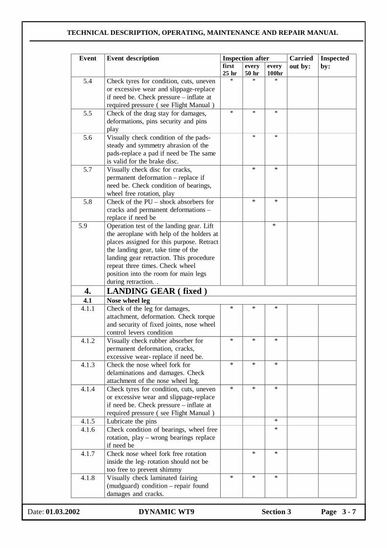
TECHNICAL DESCRIPTION, OPERATING, MAINTENANCE AND REPAIR MANUAL
Inspection after Event Event description first 25 hr
every 50 hr
every 100hr
Carried out by:
Inspected by:
5.4 Check tyres for condition, cuts, uneven or excessive wear and slippage-replace if need be. Check pressure – inflate at required pressure ( see Flight Manual )
* * *
5.5 Check of the drag stay for damages, deformations, pins security and pins play
* * *
5.6 Visually check condition of the pads-steady and symmetry abrasion of the pads-replace a pad if need be The same is valid for the brake disc.
* *
5.7 Visually check disc for cracks, permanent deformation – replace if need be. Check condition of bearings, wheel free rotation, play
* *
5.8 Check of the PU – shock absorbers for cracks and permanent deformations – replace if need be
* *
5.9 Operation test of the landing gear. Lift the aeroplane with help of the holders at places assigned for this purpose. Retract the landing gear, take time of the landing gear retraction. This procedure repeat three times. Check wheel position into the room for main legs during retraction. .
*
4. LANDING GEAR ( fixed ) 4.1 Nose wheel leg
4.1.1 Check of the leg for damages, attachment, deformation. Check torque and security of fixed joints, nose wheel control levers condition
* * *
4.1.2 Visually check rubber absorber for permanent deformation, cracks, excessive wear- replace if need be.
* * *
4.1.3 Check the nose wheel fork for delaminations and damages. Check attachment of the nose wheel leg.
* * *
4.1.4 Check tyres for condition, cuts, uneven or excessive wear and slippage-replace if need be. Check pressure – inflate at required pressure ( see Flight Manual )
* * *
4.1.5 Lubricate the pins * 4.1.6 Check condition of bearings, wheel free
rotation, play – wrong bearings replace if need be
*
4.1.7 Check nose wheel fork free rotation inside the leg- rotation should not be too free to prevent shimmy
* *
4.1.8 Visually check laminated fairing (mudguard) condition – repair found damages and cracks.
* * *
Date: 01.03.2002 DYNAMIC WT9 Section 3 Page 3 - 7

TECHNICAL DESCRIPTION, OPERATING, MAINTENANCE AND REPAIR MANUAL
Inspection after Event Event description first 25 hr
every 50 hr
every 100hr
Carried out by:
Inspected by:
4.1.9 Lubricate according to the Lubrication Chart
*
5. MAIN LANDING GEAR 5.1 Visually check of the leg for
delaminations, damages, attachment, bolts security
* * *
5.2 Visually check laminated fairing (mudguard) condition-repair found damages and cracks
* * *
5.3 Check tyres for condition, cuts, uneven or excessive wear and slippage-replace if need be. Check pressure – inflate at required pressure ( see Flight Manual )
* * *
5.4 Visually check condition of the pads-steady and symmetry abrasion of the pads-replace a pad if need be The same is valid for the brake disc.
* *
5.5 Visually check disc for cracks, permanent deformation – replace if need be. Check condition of bearings, wheel free rotation, play
* *
6. LIFTING SURFACE 6.1 Wing 6.1.1 Visually check of the wing surface for
damages, delaminations, recesses * * *
6.1.2 Check of the surface for finding out of the delaminations of the sandwich. Contact aeroplane manufacturer if are found larger areas of the delaminations.
*
6.1.3 Check plays of wing suspensions . Move the wing tip upward-downward, frontward-rearward. Contact aeroplane manufacturer if the motions are greater than 5 mm
* *
6.1.4 Check pitotstatic tube attachment at the right wing
* * *
6.2 Aileron 6.2.1 Visually check of the aileron surface for
damages, delaminations and paint damages
* * *
6.2.2 Check free movement, aileron hinge and plays
* * *
6.2.3 Check security of control rod ends * * * 6.2.4 Lubricate the bearings * 6.2.5 Check control-surface weight balance
attachment * * *
6.3 Flap 6.3.1 Visually check of the flap surface for
damages, delaminations * * *
6.3.2 Check free movement, flap hinge and plays
* * *
6.3.3 Check security of control rod ends * * *
Date: 01.03.2002 DYNAMIC WT9 Section 3 Page 3 - 8

TECHNICAL DESCRIPTION, OPERATING, MAINTENANCE AND REPAIR MANUAL
Inspection after Event Event description First 25 hr
every 50 hr
Every 100hr
Carried out by:
Inspected by:
6.3.4 Check of the flaps stops for condition at the flaps up position. Increase a prestress of the flap shaft, in case of the plays appearance.
*
7. FUSELAGE 7.1 Visually check fuselage surfaces for
delaminations and damages. Pay special attention to condition of the bottom part of the wing central panel and of the get on into cockpit zone.
* * *
7.1.2 Visually check of the room for main legs condition ( in case of the retractable landing gear )
* * *
7.1.3 Visually check of the auxiliary tail skid for attachment. Replace the auxiliary tail skid in case of a delaminations.
* * *
7.1.4 Visually check of the static pressure receivers for stoppage. ( The small opening must be clean )
* * *
7.2 Cockpit canopy 7.2.1 Visually check canopy condition for
cracks, scratches, any other damages – bore ends of cracks. Check venting windows for condition and operation.
* * *
7.2.2 Check canopy lock for condition and operation.
* * *
7.2.3 Operation test of the venting nozzles. * * * 7.2.4 Check gas struts operation – replace
those functionless * *
7.2.5 Check attached pins for condition and security
*
8. TAIL UNIT 8.1 Horizontal tail unit 8.1.1 Visually check horizontal tail unit
surfaces for delaminations and damages. Pay special attention to condition of the connection with the fin.
* * *
8.1.2 Check elevator free movement, elevator hinges and plays.
* * *
8.1.3 Check control-surface weight balance condition
* * *
8.2 Rudder 8.2.1 Visually check of the surface for
delaminations, damages. * * *
8.2.2 Check plays in the bearings and in the hinges
* * *
8.2.3 Check control cables condition * 8.2.4 Check security of control rod ends * * * 8.2.5 Check control-surface weight balance
condition in the upper ruddertip. * * *
9. COCKPIT
Date: 01.03.2002 DYNAMIC WT9 Section 3 Page 3 - 9
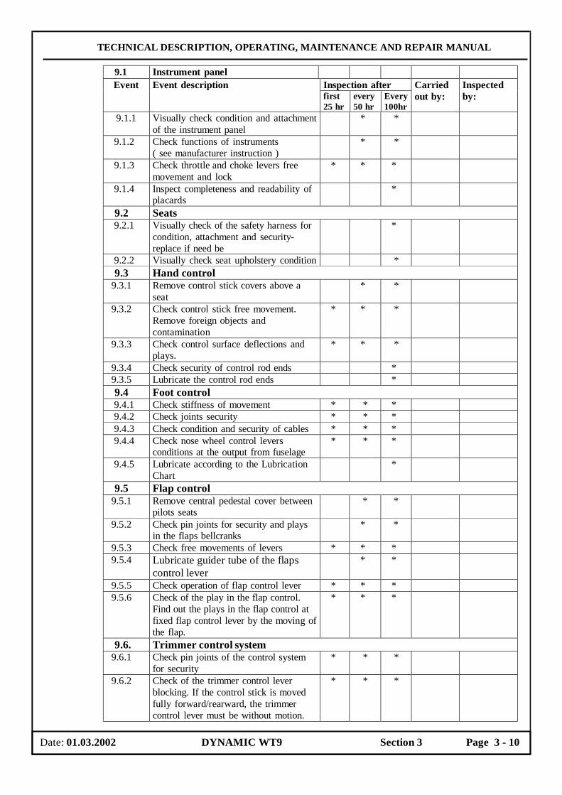
TECHNICAL DESCRIPTION, OPERATING, MAINTENANCE AND REPAIR MANUAL
9.1 Instrument panel Inspection after Event Event description first 25 hr
every 50 hr
Every 100hr
Carried out by:
Inspected by:
9.1.1 Visually check condition and attachment of the instrument panel
* *
9.1.2 Check functions of instruments ( see manufacturer instruction )
* *
9.1.3 Check throttle and choke levers free movement and lock
* * *
9.1.4 Inspect completeness and readability of placards
*
9.2 Seats 9.2.1 Visually check of the safety harness for
condition, attachment and security- replace if need be
*
9.2.2 Visually check seat upholstery condition * 9.3 Hand control 9.3.1 Remove control stick covers above a
seat * *
9.3.2 Check control stick free movement. Remove foreign objects and contamination
* * *
9.3.3 Check control surface deflections and plays.
* * *
9.3.4 Check security of control rod ends * 9.3.5 Lubricate the control rod ends * 9.4 Foot control 9.4.1 Check stiffness of movement * * * 9.4.2 Check joints security * * * 9.4.3 Check condition and security of cables * * * 9.4.4 Check nose wheel control levers
conditions at the output from fuselage * * *
9.4.5 Lubricate according to the Lubrication Chart
*
9.5 Flap control 9.5.1 Remove central pedestal cover between
pilots seats * *
9.5.2 Check pin joints for security and plays in the flaps bellcranks
* *
9.5.3 Check free movements of levers * * * 9.5.4 Lubricate guider tube of the flaps
control lever * *
9.5.5 Check operation of flap control lever * * * 9.5.6 Check of the play in the flap control.
Find out the plays in the flap control at fixed flap control lever by the moving of the flap.
* * *
9.6. Trimmer control system 9.6.1 Check pin joints of the control system
for security * * *
9.6.2 Check of the trimmer control lever blocking. If the control stick is moved fully forward/rearward, the trimmer control lever must be without motion.
* * *
Date: 01.03.2002 DYNAMIC WT9 Section 3 Page 3 - 10
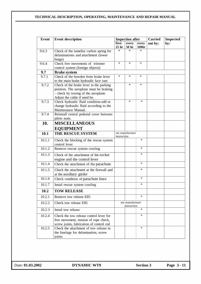
TECHNICAL DESCRIPTION, OPERATING, MAINTENANCE AND REPAIR MANUAL
Inspection after Event Event description first 25 hr
every 50 hr
every 100hr
Carried out by:
Inspected by:
9.6.3 Check of the lamellar carbon spring for delaminations and attachment (lower hinge)
* * *
9.6.4 Check free movements of trimmer control system (foreign objects)
* * *
9.7 Brake system 9.7.1 Check of the bowden from brake lever
to the main brake hydraulic face ram * * *
9.7.2 Check of the brake lever in the parking position. The aeroplane must be braking – check by towing of the aeroplane. Adjust the cable if need be.
* *
9.7.3 Check hydraulic fluid condition-add or change hydraulic fluid according to the Maintenance Manual.
* *
9.7.4 Reinstall central pedestal cover between pilots seats.
10. MISCELLANEOUS EQUIPMENT
10.1 THE RESCUE SYSTEM see manufacturer instruction
10.1.1 Check the blocking of the rescue system control lever
*
10.1.2 Remove rescue system cowling *
10.1.3 Check of the attachment of the rocket engine and the control lever
*
10.1.4 Check the attachment of the parachute *
10.1.5 Check the attachment at the firewall and at the auxiliary girder
*
10.1.6 Check condition of parachute lines *
10.1.7 Instal rescue system cowling *
10.2 TOW RELEASE
10.2.1 Remove tow release E85 *
10.2.2 Check tow release E85 see manufacturer instruction
10.2.3 Instal tow release *
10.2.4 Check the tow release control lever for free movement, tension of rope check, screw joints, lubrication of control rod
*
10.2.5 Check the attachment of tow release in the fuselage for delamination, screw joints
*
Date: 01.03.2002 DYNAMIC WT9 Section 3 Page 3 - 11
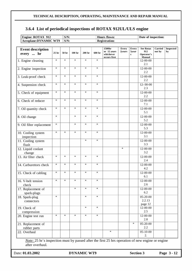
TECHNICAL DESCRIPTION, OPERATING, MAINTENANCE AND REPAIR MANUAL
3.6.4 List of periodical inspections of ROTAX 912UL/ULS engine
Engine: ROTAX 912 S/N: Hours flown: Aeroplane:DYNAMIC WT9 S/N: Registration:
Date of inspection:
Event description
every ... hr 25 hr 50 hr 100 hr 200 hr 600 hr
1500hr or 12 years whichever occurs first
Every 2years
Every5years
See Rotax 912
Operator’s Manual
Carried out by
Inspected by
1. Engine cleaning
* * * * * 12-00-00 2.1
2. Engine inspection
* * * * * 12-00-00 2.2
3. Leak-proof check
* * * * * 12-00-00 2.2
4. Suspension check
* * * * * 12- 00-00 2.3
5. Check of equipment
* * * * * 12-00-00 2.2
6. Check of reducer
* * * * * 12-00-00 7.1
7. Oil quantity check
* * * * * 12-00-00 5.1
8. Oil change
* * * * 12-00-00 5.2
9. Oil filter replacement
* * * * 12-00-00 5.3
10. Cooling system inspection
* * * * * 12-00-00 3.1
11. Cooling system flush
* * 12-00-00 3.3
12. Liquid coolant change
* 12-00-00 3.2
13. Air filter check
* * * * * 12-00-00 2.4
14. Carburettors check
* * * * * 12-00-00 4.2
15. Check of cabling
* * * * * 12-00-00 6.1
16. V-belt tension check
* * * * * 12-00-00 2.6
17. Replacement of spark-plugs
* * * 12-00-00 6.2
18. Spark-plug connectors
* * * 05-20-00 2.2.13
page 12
19. Check of compression
* * 12-00-00 2.5
20. Engine test run
* * * * * 12-00-00 2.8
21. Replacement of rubber parts
* 05-20-00 2.2
22. Overhaul
* 05-10-00 2.
Note: 25 hr`s inspection must by passed after the first 25 hrs operation of new engine or engine after overhaul.
Date: 01.03.2002 DYNAMIC WT9 Section 3 Page 3 - 12

TECHNICAL DESCRIPTION, OPERATING, MAINTENANCE AND REPAIR MANUAL
3.7 Operating media Operating media are: fuel, engine oil, liquid coolant, brake fluid. Operating media filling holes can be seen in the following Figure and they are: 1. for engine oil,
2. for liquid coolant
3.7.1 Engine oil Total oil quantity in ROTAX 912 lubricating system amount s to 3.5 litre. The oil tank is located in the engine compartment and is accessible when engine upper cowling is removed. Oil quantity is measured by wire-gage in the oil tank. The recommended oil brands are listened in the Operator’s Manual for all versions of ROTAX 912 engine. Prior to oil check, turn the propeller by hand several times to pump oil from the engine into the oil tank, or let the engine idle for 1 minute. He oil level in the oil tank should be between min. and max. mark and should not be below min. mark ( see the Operator’s Manual for all versions of ROTAX 912 engine ). For oil empying the following procedure can be applied:
- Place a suitable container for old oil below the oil tank, - Unscrew a drain screw from the bottom of the oil tank to empty oil, - Remove and replace oil filter at each oil change, - Replace a new sealing ring of the drain screw, - Fit drain screw, - Refill with approx. 3 litre of new oil.
Date: 01.03.2002 DYNAMIC WT9 Section 3 Page 3 - 13
1 2
TECHNICAL DESCRIPTION, OPERATING, MAINTENANCE AND REPAIR MANUAL
It is recommended to empty oil immediately after engine test run or a flight when is warm and better escape the engine and the oil tank. For further information see the maintenance manual for ROTAX Engine Type 912 Serie.
3.7.2 Coolant
Refer to the Operator’s Manual for all versions of ROTAX 912 engine for recommended coolant sorts. The “EVANS NPG+” is recommended by engine manufacturer. The performance of EVANs cooling liquid see www.evanscooling.com . Water or water-containing coolant must not be adedd in any case to cooling system! 3,6% water or less in the system is acceptable and may be checked with a brix scale refractometer. Residual water, if present, will vent rapidly as steam. This could further lead, by too low cooling level, in a complete failure of the cooling system. Check coolant level in expansion tank. Total coolant quantity is about 1.5 litre. The coolant level in the overflow bottle should be between min. and max. mark. In case of the coolant emptying disconnect hose leading coolant from the radiator into the pump ( on the lowest part of the cooling system ) to empty coolant into a suitable bottle. The liquid coolant fills into the expansion tank ( the highest point of the cooling system ) located in the engine compartment. In addition to that an overflow bottle is attached on the firewall to absorb coolant in case engine overheating. Run engine to operating temperature and allow engine to cool down before checking coolant level. Replenish as necessary. Oftentimes make checking coolant level during the first 10 operation hours as far as the last pneumatic blebs are removed.
3.7.3 Brake fluid Only brake fluid of J 1703c classification should be used for hydraulic brake system ( sort for middle hard or hard operation ). In general the certify automobile brake fluid meet needed requirements. Brake fluid refilling is necessary when a low brake system efficiency occurs due to fluid leak. The wheel brake system is filled with the brake fluid into the tank which is located on the main brake hydraulic face ram located beyond the rear frame of the baggage compartment. Brake fluid gets thick during aeroplane operation and absorb air humidity. This is the most important condition, which causes brake system failures. There is not possible to determine time when it occurs. The best way is to precede any troubles and change brake fluid every 2 years with new one.
3.7.4 Fuel Recommended fuel brands are introduced in the following table: Engine 912 UL/A/F Engine 912 ULS/S Minimum octane number 90 Minimum octane number 95 EN 228 Normal EN 228 Super EN 228 Super EN 228 Super plus EN 228 Super plus AVGAS 100 LL AVGAS 100 LL
For further information see the Operator’s Manual for all versions of ROTAX 912 engine.
Date: 01.03.2002 DYNAMIC WT9 Section 3 Page 3 - 14

TECHNICAL DESCRIPTION, OPERATING, MAINTENANCE AND REPAIR MANUAL
3.7.4.1 Fuelling
The total fuel tankage is 75 litre. The fuel tank filler necks are placed on a wing upper surface near of the wing root. Keep in mind maximum permitted take-off weight when tank the aeroplane.
The precaution should be kept during fuelling to prevent fire.
WARNING There is prohibited to smoke or manipulate with fire during fuelling. Under no circumstances tank with engine running. Connect the aeroplane to earth prior fuelling. No person in the cockpit during fuelling.
3.8 Lubrication 3.8.1 Lubrication fundamentals
There are some inaccessible joints and control system parts inside a wing and fuselage, which have been cleaned and lubricated during aeroplane assembly and next lubrication will be performed during a periodic inspection. On the other side there are some parts, e.g. landing gear, which are exposed to external conditions and to varying loads. Those parts would be inspected during pre-flight and periodical inspections and should be lubricated always when it necessary, but at least at intervals specified below.
3.8.2 Recommended lubricants
The manufacturer recommends to use the greases and oil without acid for the lubrication only.
Date: 01.03.2002 DYNAMIC WT9 Section 3 Page 3 - 15
TECHNICAL DESCRIPTION, OPERATING, MAINTENANCE AND REPAIR MANUAL
3.8.3 Lubricating points
Unit Lubricating point After 25hr
Every 50 hr
Every 100 hr
Lubricant
Propeller See ManufacturerManual *oil change according an engine manual
* carburettor control cable at inlet into the bowden
* * Oil the control cables
Engine
* choke control cables at inlet into the termination
* * Oil the control cables
*wheel bearings * Lubricate by grease *swing wheel fork joint pins
* * * Grease nipple Lubricate by grease
* drag stay pins * Lubricate by grease * gas strut pins * Lubricate by oil * upper and down leg pin * * Lubricate by grease
Nose wheel landing gear ( retractable undercarriage )
* swivel bearings in the cables terminations close to the nose wheel control levers
* Lubricate by grease
* wheel bearings * Lubricate by grease * upper and down leg locating bush
* * Lubricate by grease Nose wheel landing gear ( fixed undercarriage ) * joint pins of the control * * Lubricate by grease
* swing wheel fork joint pins
* * * Grease nipple Lubricate by grease
* drag stay pins * * Lubricate by grease * hydraulic face rams pins
* Lubricate by grease
Main landing gear (retractable undercarriage )
* wheel bearings * Lubricate by grease Hand control *control stick bearings
and all movable joints * Lubricate by grease
Foot control * all movable joints * Lubricate by grease *supporting bearings * * Lubricate by grease Ailerons *rod end bearings * * Lubricate by grease *sliding bearings * Lubricate by grease Rudder *rudder lever pins * * Lubricate by grease * all movable joints * * Lubricate by grease Elevator *supporting bearings * Lubricate by grease * rod sliding bearings * Lubricate by grease *rod joint pins * Lubricate by grease
at each flaps disassembly
Flaps
*Changing gate guided a flap control lever in the pedestal between the pilot seats
* * Lubricate by HHS 2000 oil (Würth Firm)
Date: 01.03.2002 DYNAMIC WT9 Section 3 Page 3 - 16
TECHNICAL DESCRIPTION, OPERATING, MAINTENANCE AND REPAIR MANUAL
3.9 Mechanisms adjustments 3.9.1 Torque moments
Strength class Metric thread 4D 5D 4S 6E 5S 5R 6S 8G 10K 12K M4 N.m
Kg.m 1,67
0,17
M5 N.m kg.m
3,45 0,35
M6 N.m kg.m
4,31 0,44
4,90 0,50
5,39 0,55
5,88 0,60
6,86 0,70
7,84 0,80
8,33 0,85
9,80 1,00
13,72 1,40
16,67 1,70
M7 N.m kg.m
5,88 0,60
7,84 0,30
8,82 0,90
9,80 1,00
10,78 1,10
11,76 1,20
12,74 1,30
14,70 1,50
20,59 2,10
25,49 2,60
M8 N.m kg.m
8,33 0,85
10,78 1,10
12,74 1,30
13,72 1,40
15,69 1,60
17,65 1,80
19,61 2,00
22,55 2,30
32,36 3,30
38,24 3,90
M10 N.m kg.m
16,18 1,65
21,57 2,20
24,51 2,50
27,45 2,80
31,38 3,20
34,32 3,50
37,26 3,80
44,12 4,50
61,78 6,30
73,54 7,50
M12 N.m kg.m
27,45 2,80
36,28 3,70
42,16 4,30
47,07 4,80
52,95 5,40
58,83 6,00
63,74 6,50
74,53 7,60
104,93 10,70
125,52 12,80
M14 N.m kg.m
43,14 4,4
58,83 6,00
66,68 6,80
73,54 7,50
78,54 8,00
93,16 9,50
98,06 10,00
117,67 12,00
164,75 16,80
196,13 20,00
M16 N.m kg.m
60,80 6,20
78,45 8,00
93,13 9,5
98,06 10,00
107,87 11,50
127,48 13,00
131,29 14,00
164,75 16,80
225,55 23,00
274,58 28,00
M18 N.m kg.m
88,25 9,00
117,67 12,0
137,29 14,00
156,90 16,00
171,61 17,50
196,13 20,00
205,93 21,00
245,16 25,00
343,23 35,00
411,87 42,00
M20 N.m kg.m
117,67 12,00
156,90 16,00
176,51 18,00
196,13 20,00
225,55 23,00
245,16 25,00
274,58 28,00
313,81 32,00
441,29 45,00
539,36 55,00
M22 N.m kg.m
147,09 15,00
196,13 20,00
225,55 23,00
245,16 25,00
284,39 29,00
313,81 32,00
33,42 34,00
392,26 40,00
558,97 57,00
676,65 69,00
M24 N.m kg.m
205,93 21,00
274,58 28,00
313,81 32,00
353,03 36,00
392,26 40,00
441,29 45,00
470,71 48,00
549,17 56,00
755,11 77,00
970,85 99,00
Ultimate strength 37 50 37 - 50 - 60 80 100 120
ϑ in % 25 22 14 - 7 - 8 12 8 8 Yield point 21 28 32 36 40 45 48 64 90 108
Torque moment formula ( valid for all bolt size ) : d . σ . S
Mkmax = 1,065 x m
Legend: Mk …………….. Torque moment kg.cm d…………... Bolt shank diameter cm
σ………….. Minimum yield point kg/cm2
m…………. Safety factor ( m = 1,25 pre σ<50 kg/mm2, m = 1,43 pre σ>50 kg/mm2 )
S.………….. Lead of helix cm
Date: 01.03.2002 DYNAMIC WT9 Section 3 Page 3 - 17

TECHNICAL DESCRIPTION, OPERATING, MAINTENANCE AND REPAIR MANUAL
3.9.2 Necessary maintenance tools
No special tools are needed for DYNAMIC WT9 maintenance. The manufacturer recommends using of the suitable piercer for dismantling of the nose wheel axle.
3.9.3 Inspection holes There are not use the special inspection holes for an access into the airframe on the ground of preservation of the smooth aeroplane surface. There is an inspection window blinded by transparent acryl glass on the wing lower surface for the inspection of the aileron two-arm lever. After opening of this small window and the finishing of the works glue it by means of a pure silicon glue again. The control elements are accessed after the pedestal cover demounting and the rear frame cover demounting behind the baggage compartment.
3.10 Brake system 3.10.1 Brake plate replacement The brake plate replacement is performed when a plate is worn-out. Apply the following
procedure to brake plate replacement: 1. Jack the aeroplane 2. Remove the cotter pin, unscrew the M22 main wheel axle nut, remove washer from
the wheel axle. 3. Bend small tabs on 3 washers and unscrew screws connecting brake disc to the rim.. 4. Remove the wheel and a distance ring from the axle. 5. Take the brake disc down ( leave the brake on a main leg ). 6. Remove the cotter pins, shift the pins out and remove the brake plates. 7. Mount a new brake plates, secure the pins with cotter pins ( diameter 2 mm, length
14 mm ). 8. Put the brake disc on the wheel. 9. Put the distance ring on the axle and then the wheel ( adjust the distance ring between
bearings ). 10. Set tab washers on the screws, apply a Loctite and screw the brake disc to the inner
part of a rim, bend the tabs of washers to secure screw heads. 11. Put the washer on the axle, screw main wheel axle nut back and secure with a cotter
pin.
List of parts necessary for Brake plate replacement procedure: 1. Brake plates 4 pcs 2. Cotter pins φ2 x 14 4 pcs 3. Cotter pins φ4 x 40 2 pcs 4. Secure Tab washers 6x2 6 pcs 5. LOCTITE ( blue ) to secure the screw heads
Date: 01.03.2002 DYNAMIC WT9 Section 3 Page 3 - 18
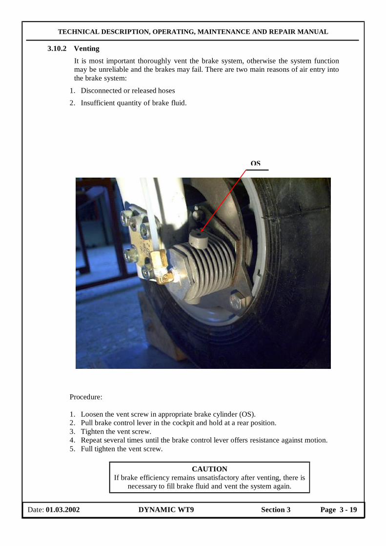
TECHNICAL DESCRIPTION, OPERATING, MAINTENANCE AND REPAIR MANUAL
3.10.2 Venting It is most important thoroughly vent the brake system, otherwise the system function may be unreliable and the brakes may fail. There are two main reasons of air entry into the brake system:
1. Disconnected or released hoses
2. Insufficient quantity of brake fluid. Procedure:
1. Loosen the vent screw in appropriate brake cylinder (OS). 2. Pull brake control lever in the cockpit and hold at a rear position. 3. Tighten the vent screw. 4. Repeat several times until the brake control lever offers resistance against motion. 5. Full tighten the vent screw.
CAUTION If brake efficiency remains unsatisfactory after venting, there is
necessary to fill brake fluid and vent the system again.
Date: 01.03.2002 DYNAMIC WT9 Section 3 Page 3 - 19
OS

TECHNICAL DESCRIPTION, OPERATING, MAINTENANCE AND REPAIR MANUAL
3.10.3 Brakes adjustment
The brakes adjustment carries out after the brake system venting and after a brake plate replacement. The main landing wheels are braked together by means of the brake control lever pulling in the cockpit. The brake effect adjustment is carried out at the brake control lever in the cockpit. Bowden cable leads from the brake control lever to the main brake hydraulic face ram, it is adjusted so that at rear detent position of the brake control lever ( a parking position ) the aeroplane is full braked.
3.11 Control surfaces deflections setting
Control surfaces deflections of a new aeroplane are set by the manufacturer. Deflections are adjusted at values specified in Control Surfaces Deflections Record enclosed in this Manual. A neutral position of control surfaces and controls is a base for adjustment of deflections.
3.11.1 Aileron deflections adjustment ( see Lateral control system scheme )
The range of the control stick deflection is adjusted by stops (AS) on the consoles of the torsional tube (TR). Aileron deflections can be adjusted with adjustable threaded end of a short rod (5). Further adjustable rode ends are located at a place a pin joint (BV), which allows a disconnection of the rod in case of a derigging of a wing. An access to this joint (BV) is allowed through an access hole at a model with a fixed undercarriage and through a main wheel well at a model with a retractable undercarriage. Deflection of the two-arm lever (4) , which a console with the bearings is attached at the wing main spar and provides a necessary differentiation of the aileron deflections, is set by the manufacturer and can not be adjusted in operation.
3.11.2 Elevator deflections adjustment ( see Longitudinal control system scheme )
The control stick motions are limited by two stops (7). A “push-down” stop is glued into the wing central panel main spar. A “pull-up” stop is on the lateral located tube, which is passed through the walls of the middle console between the seats. An adjustment of the stops is allowed after removal of the pedestal upper cover. Elevator deflections can be adjusted with adjustable threaded rod end (2).
3.11.3 Trimming deflections adjustment
A neutral position of a trim control lever can be adjusted by means of a adjustment of a length of the rod (9). An adjustable nut is accessible after removal of the pedestal upper cover between seats.
3.11.4 Flap deflections adjustment
Set flap position is locked by the deflection of the flap control lever into the appropriate recesses on the pedestal cover, where a lever is pushed by a spring. A neutral position of each flap adjusts by means of an adjustment of an adjustable short rod end (6). A common neutral position of the flaps can be adjusted by means of an adjustment of an adjustable rod end (3). An access to this joint is allowed after removal of the pedestal upper cover between seats.
Date: 01.03.2002 DYNAMIC WT9 Section 3 Page 3 - 20

TECHNICAL DESCRIPTION, OPERATING, MAINTENANCE AND REPAIR MANUAL
3.11.5 Rudder deflections adjustment The rudder deflections are set by the aeroplane manufacturer by means of corresponding length of the control cables and can not be adjusted in operation.
3.12 Nose wheel leg flexible polyurethane roller replacement 3.12.1 Fixed undercarriage
The springing is carried out by means of the gilled flexible polyurethane roller, which is located in the upper nose wheel bearing bush (1) and by means of the rubber ropes twisted around a leg (1) and bearing console pin (B). At the gilled flexible polyurethane roller replacement must be the nose wheel leg demounted. Procedure: 1. Remove both engine cowlings.
2. Disconnect both pin joints of the nose wheel control rod.
3. Loosen the screws (2) of the lower bearing bush (LG) and a part of the bearing bush together with a nose wheel leg pull read forward through a groove inside console (B).
4. Eject a leg from a upper bearing bush so that the gilled flexible polyurethane roller can be replaced.
5. Pull the gilled flexible polyurethane roller and replace new one.
6. Assemble back the nose wheel leg in inverted sequence. Fig. Nose wheel leg of the fixed undercarriage mounting
Date: 01.03.2002 DYNAMIC WT9 Section 3 Page 3 - 21
B
1
2
LG
TECHNICAL DESCRIPTION, OPERATING, MAINTENANCE AND REPAIR MANUAL
3.13 Tire inflating Main wheel pressure………………….. 250 kPa
Nose wheel pressure……………….…. 200 kPa
Wheels pressures for tires are stated on placards stuck on the aeroplane, also. A car pump or a compressor or a pressure bottle may be used to pump a wheel.
3.14 Winter operation 3.14.1 General
The aeroplane is considered as a winter one, if outside temperature falls below + 5°C , the aeroplane must be prepared for winter operation.
3.14.2 Preparing the aeroplane for winter operation Aeroplane airframe:
• Lubricate the aeroplane per Lubricating Chart, if from the last 100 hrs. Inspection did not pass more than 6 months.
• Check fuel tank venting. • Check attachment of wing, ailerons, flaps and tail units; lubricate per Lubricating
Chart. Power plant
• The cooling system of the cylinder heads is filled with the mixture of the non-freezing liquid and water, which protects the cooling system against the freezing up to – 18 ° C. If the temperature is below this value, the coolant must be drained or renewal with pure the non-freezing liquid. The coolant must be renewal after each two years. Use only coolant according to the current Operator’s Manual for engine ROTAX 912 UL / 912 ULS.
• Fill engine oil suitable for low temperatures. The required operation oil temperature and operation temperature of the coolant are not reached in the winter operation. The oil temperature must be higher than 90°C.
• Cover the oil cooler face or a part of face only. Cover a part of radiator face by means of a width adhesive tap so, that is a small 10 – 15 cm width slot for cooling and for the inlet of air for the heating. The oil tank must be isolated by means of suitable thermal insulation in case of the lower outside temperatures.
CAUTION The limit temperatures of the coolant, cylinder heads and oil
must be kept after these arrangements.
• Check electrode gap of the spar plugsand adjust as necessary or renew as required.
Date: 01.03.2002 DYNAMIC WT9 Section 3 Page 3 - 22
TECHNICAL DESCRIPTION, OPERATING, MAINTENANCE AND REPAIR MANUAL
3.14.3 Operation Preflight inspection In addition to the Pre-flight inspection events in Aeroplane Flight Manual ( AFM ) , the following would be done: • Throw down or ice from aeroplane surfaces • Check control surfaces for free movement and cleanness of slots of control surfaces
and flaps • Check cleanness and passage of the fuel tank venting before each flight • Check fuel system ( fuel filter ) for frail, if found than empty the fuel tank and refill
with new one • Check fuel for water prior filling • Drain fuel tank, deflate a small quantity of a fuel. • If the aeroplane is equipped with a tricycle type of fixed undercarriage, for the winter
operation on the frozen or harden surface of the runway is recommended to remove the spats from the wheels due to their damages.
Pre-heating engine and oil There is possible to start an engine without need of pre-heating if outside temperature is not below + 5°C. It is recommended to pre-heat the engine and oil if temperature falls below + 5°C. Use suitable air heater or a dryer.
WARNING Never use open fire to pre-heat an engine.
Blow hot air from the front into the hole around the propeller hub . Temperature of hot air should not exceed 100°C. Pre-heat until cylinder head temperature and oil temperature exceed + 20°C.
Engine starting
1. Turn the propeller by hand ( ignition switched off )
2. Open the fuel cocks
3. Set throttle lever for idle run
4. Open the choke
5. Switch on Master switch
6. Turn the key in the switch box
7. Switch on ignition switches
8. Push the starter button to start the engine
9. Adjust engine run after starting
10. Close the choke
11. Warm up the engine, check oil pressure
Date: 01.03.2002 DYNAMIC WT9 Section 3 Page 3 - 23

TECHNICAL DESCRIPTION, OPERATING, MAINTENANCE AND REPAIR MANUAL
CAUTION If cylinder heads and oil temperatures fall during parking among flights than is recommended to start and warm up engine from
time to time. Do not open choke when starting hot engine. Parking and taxiing
Check wheel brakes for freezing when parking outside and temperature is below 0°C. Check wheels free rotation prior to taxiing ( hold a propeller and tow an aeroplane ). Heat the brakes with hot air to remove freezing. Freezing should not be removed by force towing. After winter operation • Clean the aeroplane thoroughly • Lubricate the aeroplane per Lubricating Chart • Check and adjust the control system
Date: 01.03.2002 DYNAMIC WT9 Section 3 Page 3 - 24
TECHNICAL DESCRIPTION, OPERATING, MAINTENANCE AND REPAIR MANUAL
SECTION 4
REPAIRS
Page 4.1 Repair outlines 4-2
4.2 Repair classification 4-2
4.3 Construction 4-2
4.4 Materials 4-2
4.5 Repair preparation 4-3
4.6 Repair class 4 4-4
4.7 Repair class 3 4-4
4.8 Repair class 2 4-4
4.9 Repair class 1 4-6
4.10 Repairs of a metal parts 4-6
4.11 Test flight after a repair 4-6
Date: 01.03.2002 DYNAMIC WT9 Section 4 Page 4 - 1

TECHNICAL DESCRIPTION, OPERATING, MAINTENANCE AND REPAIR MANUAL
4.1 Repair outlines
Describe procedures apply to minor damages only. Major repairs can be carried out by the aeroplane manufacturer or a repair workshop approved by local Civil Aviation Authority ( CAA ). Under decscribed procedures are general. For each part are used different cloths. For repair of any damage class 3 or bigger ask the manufactuurer for cloths arrangement. The sandwich shells, from which is aeroplane made, are repaired very difficult.
4.2 Repair classification The repairs are divided according to the influence to the airworthiness of all aeroplane into following classes: Repair class 1: Large damages required a partial replacement of the airframe important
or large repairs can be carried out by the aeroplane manufacturer or a repair workshop approved by local Civil Aviation Authority.
Repair class 2: Destruction of the whole shell ( also the inner glass fiber laminate
destroyed ), however small size only. Repair class 3: Simple surface damage ( only the outer glass fiber laminate damaged )
and small damage of the foam filling. Repair class 4: The erosion damages caused by the scores and the scrapes without the
outer glass fiber laminate damage and without the breakage of the element.
4.3 Construction
DYNAMIC WT9 airframe consists of a sandwich shells from advanced composite material. The shell is of three layer construction. The external and internal shell layers are made of a carbon and glass fiber fabrics, which are saturated with a resin. Between them there is a filling from a hard foam panels ( Polyurethane foam HEREX 3 – 8 mm thick ).
4.4 Materials
The following materials apply to all advanced composite material parts:
Resin : L 285 type Manufacturer Scheufler Firm
Hardener : L 286 type Manufacturer Scheufler Firm Mixing proportions by weight : 100 resin to 38 hardener Mixing proportions by volume : 2 resin to 1 hardener
Date: 01.03.2002 DYNAMIC WT9 Section 4 Page 4 - 2

TECHNICAL DESCRIPTION, OPERATING, MAINTENANCE AND REPAIR MANUAL
The given mixing proportion of components must be observed as exactly as possible. Mixture of a resin and a hardener must be stirred thoroughly until there are no cloudiness and no bubbles in a vessel. The thickeners and the resin-fillers are added after stirring. The hardening of the mixture is 15 hours at a temperature 55 °C. The mixture reaches final properties after this time. Reinforcements: Glass clothes
INTERGLAS Style
Weave Weight g/m2
Application
91110 Crosstwill 110 Inner skins 92110 Crosstwill 163 Fuselage, wing, control
surfaces 92125 Crosstwill 285 Fuselage, wing 92145 Unidirectional 216 Fuselage, wing
Carbon clothes CF 200 Cloth 200 Fuselage CF 140 Unidirectional 140 Fuselage, stabilizer CF 80 Cloth 80 Fuselage; control surfaces CF 80 Unidirectional 80 Fuselage CF/AR 160 Cloth 160 Fuselage; cabin part
Rovings Carbon : TENAX HTA 5131 (KDU 380 =)
Glass : EC9-756 K43
Foams : HEREX C.70.55 Resin - Fillers : Aerosil, Chopped cotton wool, Microballoons
white
Lacquer : Acryl Steel : L-CM3.9 ( AISI 4130, DIN 1.7214.4 )
L-CM3.7 ( AISI 4130, DIN 1.7214.4 ) Light metals : Duralumin Z 424203.61 ( ASM 2024 )
4.5 Repair preparation
You should first inspect the damaged area to determine exactly the extent of damage, type of construction and type and density of weave concerning to main dimensions of the part. The aeroplane DYNAMIC WT9 has the first layer of the sandwich outer layers from the 92110 cloth with 45 ° diagonal weave direction to the fuselage centre line or to the wing centre line. The first step is removing all damage parts and all portion of the shell which has become delaminated from a damage area. A repair area should be washed with a soap and dried up. Then clean a repair area with carbon tetrachloride or acetone. Prepare clean vessels for stirring the mixtures of a resin and a hardener.
Date: 01.03.2002 DYNAMIC WT9 Section 4 Page 4 - 3

TECHNICAL DESCRIPTION, OPERATING, MAINTENANCE AND REPAIR MANUAL
4.6 Repair class 4
The erosion damages caused by the rain, the scores, the scrapes without the outer glass fiber laminate damage require the lacquer works only. Suitable is PE – Lackvorgelat , white No.3-69469 and PE – Hardener No. 07-20500. Mixing proportions by weight 100 parts Lackvorgelat to 10 parts hardener. The lacquer remains to gell ( appr. 30 minutes ) for filling more deep scrapes. In case of first cloth layer damage, then whole repair area cleans well and sands smooth with an abrasive paper. Lay on the cloth layer and, if the resin is dry, the repair area can be puttied and repainted with lacquer.
4.7 Repair class 3 If the outer shell receives a puncture or a fracture, tap to determine the extent of delamination from the foam. Follow by removing the lacquer with a sanding disc or block and remove from the foam the portion of the shell which has become delaminated. Around the edge of the damaged area where the shell is still firmly bonded, scarf with an abrasive block or a plane blade at least 4 cm ( for each cloth layer about 15 mm is necessary ). After scarfing the shell, blow out thoroughly the whole repair area including the pores of the foam and wash the scarf with carbon tetrachloride or acetone. Now fill the hole in the foam with microballoons and simultaneously fill the pores of the exposed foam. Then lay two patches of the 92110 cloth with diagonal weave direction ( stepwise largest patch first ) over the damaged area. The applied cloth must be dry and dust free. After hardening ( appr. 8 hrs at 20°C ) the damaged area should be smoothed, filled and painted. In smoothing take care that only the edges of the patches are sanded.
An Example - Fuselage front part
4.8 Repair class 2
If there is a through hole in the sandwich shell then the inner laminate must be repaired. We remove the outer laminate in the region of the region of the damage which is no longer bonded to the foam and enlarge the hole in the foam and inner laminate until good bonding to the foam is evidenced. Then the foam is further removed 20 mm around the hole in the inner laminate and the outer laminate scarfed as under Repair class 3.
Date: 01.03.2002 DYNAMIC WT9 Section 4 Page 4 - 4
Inner laminate
Outer laminate 1. layer 91 110 diagonal 2. layer CF 140 unidirectional
*1. layer CF 80 diagonal *2. layer CF 140 unidirectional
* layers for model LW
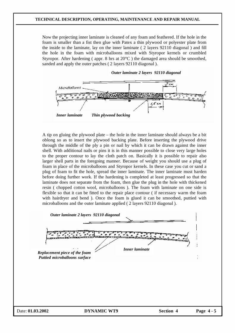
TECHNICAL DESCRIPTION, OPERATING, MAINTENANCE AND REPAIR MANUAL
Now the projecting inner laminate is cleaned of any foam and feathered. If the hole in the foam is smaller than a fist then glue with Patex a thin plywood or polyester plate from the inside to the laminate, lay on the inner laminate ( 2 layers 92110 diagonal ) and fill the hole in the foam with microballoons mixed with Styropor kernels or crumbled Styropor. After hardening ( appr. 8 hrs at 20°C ) the damaged area should be smoothed, sanded and apply the outer patches ( 2 layers 92110 diagonal ).
A tip on gluing the plywood plate – the hole in the inner laminate should always be a bit oblong so as to insert the plywood backing plate. Before inserting the plywood drive through the middle of the ply a pin or nail by which it can be drawn against the inner shell. With additional nails or pins it is in this manner possible to close very large holes to the proper contour to lay the cloth patch on. Basically it is possible to repair also larger shell parts in the foregoing manner. Because of weight you should use a plug of foam in place of the microballoons and Styropor kernels. In these case you cut or sand a plug of foam to fit the hole, spread the inner laminate. The inner laminate must harden before doing further work. If the hardening is completed at least progressed so that the laminate does not separate from the foam, then glue the plug in the hole with thickened resin ( chopped cotton wool, microballoons ). The foam with laminate on one side is flexible so that it can be fitted to the repair place contour ( if necessary warm the foam with hairdryer and bend ). Once the foam is glued it can be smoothed, puttied with microballoons and the outer laminate applied ( 2 layers 92110 diagonal ).
Date: 01.03.2002 DYNAMIC WT9 Section 4 Page 4 - 5
Outer laminate 2 layers 92110 diagonal
Inner laminate Thin plywood backing
Outer laminate 2 layers 92110 diagonal
Inner laminate Replacement piece of the foam Puttied microballoons surface

TECHNICAL DESCRIPTION, OPERATING, MAINTENANCE AND REPAIR MANUAL
4.9 Repair class 1 These repairs have serious character and can be carried out by the aeroplane manufacturer or a repair workshop approved by local Civil Aviation Authority ( CAA ). In any case contact the aeroplane manufacturer.
4.10 Repairs of a metal parts In case of a damage of any fittings, if a damage reason was not designate immediately, contact the aeroplane manufacturer. It is necessary take account to an element function, a material composition, a processing technology and etc. The aeroplane manufacturer can evaluate all these factors only. Welding should be carried out only by an approved aircraft welder. All weldments made by the aeroplane manufacturer are by the Argon-arc welding method.
4.11 Test flight after a repair
CAUTION Only qualified pilot may perform a test flight. .
The test flight should be performed above all in following cases: After repair or replace of fixed surfaces – wing, fin, stabilizer, or control surfaces – elevator, aileron or flap. Flight characteristics and aeroplane stability can be affected when above mentioned part is replaced or adjusted. Therefore a test flight should be performed to check aeroplane flight characteristics, control surfaces setting, maneuverability, stability and stall characteristics. The characteristics are check during taxiing, takeoff, climbing, cruise, descent, approach and landing. Use the Flight Test Record ( see Section 5, Appendices, of this Manual ) to record data obtained during a test flight.
Test flight flying time Test flight flying time takes about 40 minutes if the test flight is performed according to the Flight Test Record.
Aeroplane inspection before a Test flight Prior to the test flight the aeroplane should be thoroughly inspected, weighed, found faults debugged and the aeroplane should be prepared for the flight ( tank etc. ).
Test crew Only qualified persons ( test pilots ) are permitted to perform a test flight. In-flight found faults should be debugged forthwith the test flight.
Date: 01.03.2002 DYNAMIC WT9 Section 4 Page 4 - 6

TECHNICAL DESCRIPTION, OPERATING, MAINTENANCE AND REPAIR MANUAL
SECTION 5
APPENDICES
Page 5.1 List of Appendices 5-2
5.1.1 Control Surfaces Deflections Record 5-2
5.1.2 Magnetic Compass Compensation Record 5-3
5.1.3 Checking Control Surfaces Weights and Balancing 5-4
5.1.4 Flight Test Record 5-5
5.1.5 Pitot-static system for leak proof Test Record 5-6
5.1.6 Weight and Balance Record 5-7
5.1.7 Measurement Record – ZKM Encoding Altimeter 5-8
5.1.8 Measurement Record – ZKM Radio Station VHF 5-9
5.1.9 Measurement Record – ZKM Transponder 5-10
5.1.10 Delivery Record 5-11
5.1.11 Aeroplane Wiring diagrams 5-12
Date: 01.03.2002 DYNAMIC WT9 Section 5 Page 5 - 1
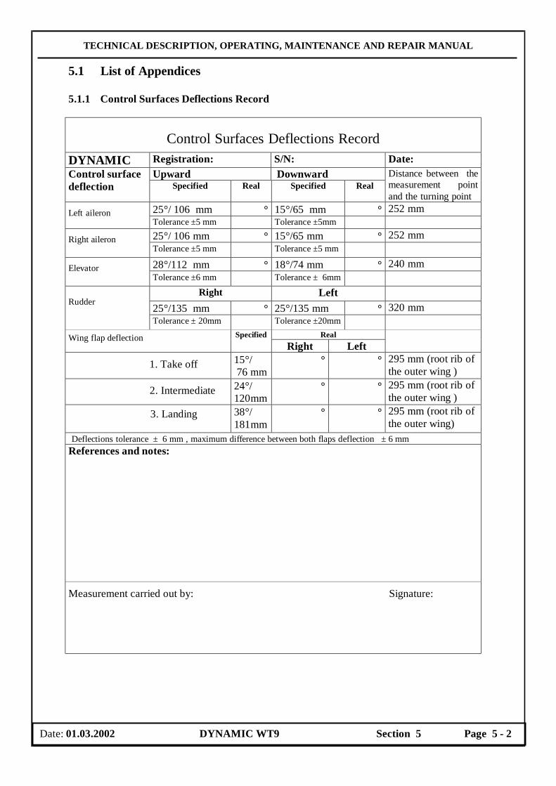
TECHNICAL DESCRIPTION, OPERATING, MAINTENANCE AND REPAIR MANUAL
5.1 List of Appendices 5.1.1 Control Surfaces Deflections Record
Control Surfaces Deflections Record DYNAMIC Registration: S/N: Date:
Upward Downward Control surface deflection Specified Real Specified Real
Distance between the measurement point and the turning point
25°/ 106 mm ° 15°/65 mm ° 252 mm Left aileron Tolerance ±5 mm Tolerance ±5mm 25°/ 106 mm ° 15°/65 mm ° 252 mm Right aileron Tolerance ±5 mm Tolerance ±5 mm 28°/112 mm ° 18°/74 mm ° 240 mm Elevator Tolerance ±6 mm Tolerance ± 6mm
Right Left 25°/135 mm ° 25°/135 mm ° 320 mm
Rudder
Tolerance ± 20mm Tolerance ±20mm Real Wing flap deflection Specified
Right Left
1. Take off 15°/ 76 mm
° ° 295 mm (root rib of the outer wing )
2. Intermediate 24°/ 120mm
° ° 295 mm (root rib of the outer wing )
3. Landing
38°/ 181mm
° ° 295 mm (root rib of the outer wing)
Deflections tolerance ± 6 mm , maximum difference between both flaps deflection ± 6 mm References and notes:
Measurement carried out by: Signature:
Date: 01.03.2002 DYNAMIC WT9 Section 5 Page 5 - 2
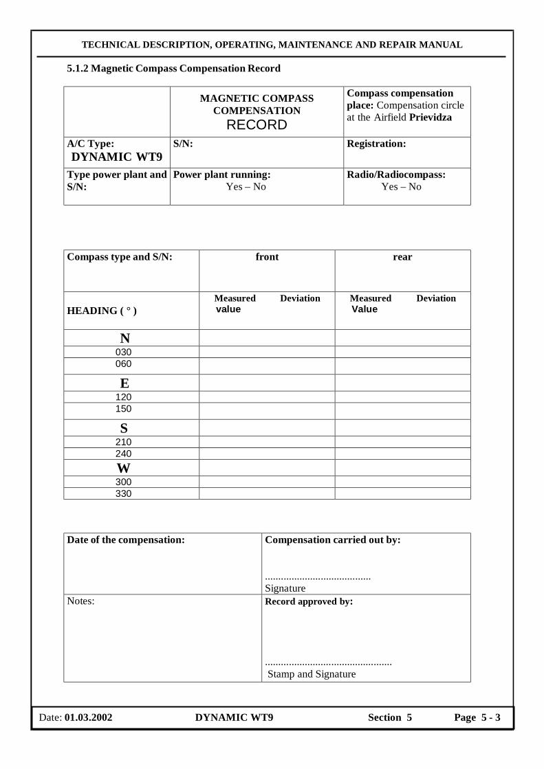
TECHNICAL DESCRIPTION, OPERATING, MAINTENANCE AND REPAIR MANUAL
5.1.2 Magnetic Compass Compensation Record MAGNETIC COMPASS
COMPENSATION RECORD
Compass compensation place: Compensation circle at the Airfield Prievidza
A/C Type: DYNAMIC WT9
S/N: Registration:
Type power plant and S/N:
Power plant running: Yes – No
Radio/Radiocompass: Yes – No
Compass type and S/N:
front rear
HEADING ( ° )
Measured Deviation value
Measured Deviation Value
N 030 060
E 120 150
S 210 240 W 300 330 Date of the compensation: Compensation carried out by:
........................................ Signature
Notes: Record approved by: ................................................ Stamp and Signature
Date: 01.03.2002 DYNAMIC WT9 Section 5 Page 5 - 3

TECHNICAL DESCRIPTION, OPERATING, MAINTENANCE AND REPAIR MANUAL
5.1.3 Checking Control Surfaces Weights and Balancing
AEROSPOOL Prievidza
CHECKING CONTROL SURFACES WEIGHTS AND BALANCING
WT 9 DYNAMIC (WT 9 DYNAMIC LW)
Registration: S/N: Date:
Without balancing With balancing Specified values Specified values Real values
Control surface
weight (kg) st. moment ( Ncm)
weight (kg) st. moment ( Ncm)
weight (kg) st. moment ( Ncm)
Aileron Right
Left
0,77- 0,95 (0,70- 0,90) 0,77- 0,95 (0,70- 0,90)
70 – 100 (70 – 100)
1,00-1,25 (0,90-1,10) 1,00-1,25 (0,90-1,10)
20-60 (10 – 46)
Arm l = 252 mm ( the distance between rotation axis of the control surface and weighting point )
Note:
Elevator Right Left
1,00-1,20 (0,80-1,00) 1,00-1,20 (0,80-1,00)
60-85 (42 – 54)
1,15-1,40 (0,95-1,15) 1,15-1,40 (0,95-1,15)
30- 68 (30- 38)
Arm l = 240 mm ( the distance between rotation axis of the control surface and weighting point ) Note:
Rudder
1,50- 1,90 (1,05- 1,30)
40- 70 (40- 80)
1,75- 2,25 (1,25-1,65)
-40 do –20 (-50 - 0 )
Arm l = 320 mm ( the distance between rotation axis of the control surface and weighting point ) Note:
Wing flap Right Left
2,50- 3,30 (1,75- 2,25) 2,50-3,30 (1,75- 2,25)
180-220 (145-180)
3,50-4,70 (2,25-2,90) 3,50-4,70 (2,25-2,90)
-20do+25 (70 – 92)
The static moment is measured on root rib at arm distance l = 320 mm. Note:
Checking static moment of the control surfaces are within the approved tolerances. Prievidza, date ........................ ..................................................... Checking carried out by
Date: 01.03.2002 DYNAMIC WT9 Section 5 Page 5 - 4

TECHNICAL DESCRIPTION, OPERATING, MAINTENANCE AND REPAIR MANUAL
5.1.4 Flight Test Record
Flight Test Record Take-off weight: Model:DYNAMIC WT9 S/N: Registration: Engine: R 912 ULS S/N: Hours flown: Propeller: SR 2000 S/N: No. of take-offs:
RESULTS: ( Airspeed are IAS ) Regime Test
On ground pressure QNH HPa On groun temperature QMU o C
Meteorological conditions
Wind direction / velocity o/ m/s Engine speed 4900±200 rpm rpm Oil temperature 50oC o C Oil pressure 1.5 – 5.0 bar bar
Full throttle
Ignition check 3850 rpm Engine speed drop max 300 rpm with either magneto switched off
L: R:
Engine check
Idling 1400 + 100 rpm rpm Engine speed max. 5500 rpm rpm Oil pressure 1.5 – 5.0 bar bar Oil temperature 130oC o C CHT 135oC o C
Take-off and climbing to 1000 m ISA ( 3300 ft ) IAS = 120 km/h ( 65 kts )
Time of climbing 300-1000 m ISA (1000-3300 ft)
min
Landing configuration (flaps fully extended) VSO = 50 km/h ( 27 kts )
km/h Stalling speed at idling
Cruise configuration VS1 = 60 km/h ( 33 kts )
km/h
Steep turns max. 45o s VNE = 270 km/h IAS ( 262 CAS )
km/h Never exceed speed
Engine speed max. 5800 rpm km/h Airspeed at 5000 rpm min. 160 km/h IAS ( 156 CAS ) 86 kts IAS ( 84 CAS )
km/h
Oil temperature 90-110oC o C
Cruising speed at engine speed: Altitude 500 m ISA ( 1650 ft ) 4800- km/h 5000- km/h 5200- km/h 5500- km/h
CHT 60-135oC o C Airspeed at 5750 rpm min. 220 km/h IAS ( 215 CAS )
km/h
Oil temperature 90-130oC o C
Maximum horizontal speed Altitude 500 m ISA ( 1650 ft )
CHT 60-135oC o C Landing Touch down speed km/h Date: Pilot´s signature: Report: Flight Test Results comply with Type Certificate.
Date: 01.03.2002 DYNAMIC WT9 Section 5 Page 5 - 5
TECHNICAL DESCRIPTION, OPERATING, MAINTENANCE AND REPAIR MANUAL
5.1.5 Pitot-static system for leak proof Test Record
Pitot - static system for leak proof Test Record A/C Type: Dynamic WT9 S/N.: Registration: Date: There is a measured decrease in the static pressure system: …........km/h per 5 min. Tested at airspeed indicator reading.....................................km/h. Carried out by:……………………………………………………. Leakage place: ................................................................................. Repair process : ............................................................................ Repair carried out by: ...................................... Signature: ......................................
Date: 01.03.2002 DYNAMIC WT9 Section 5 Page 5 - 6
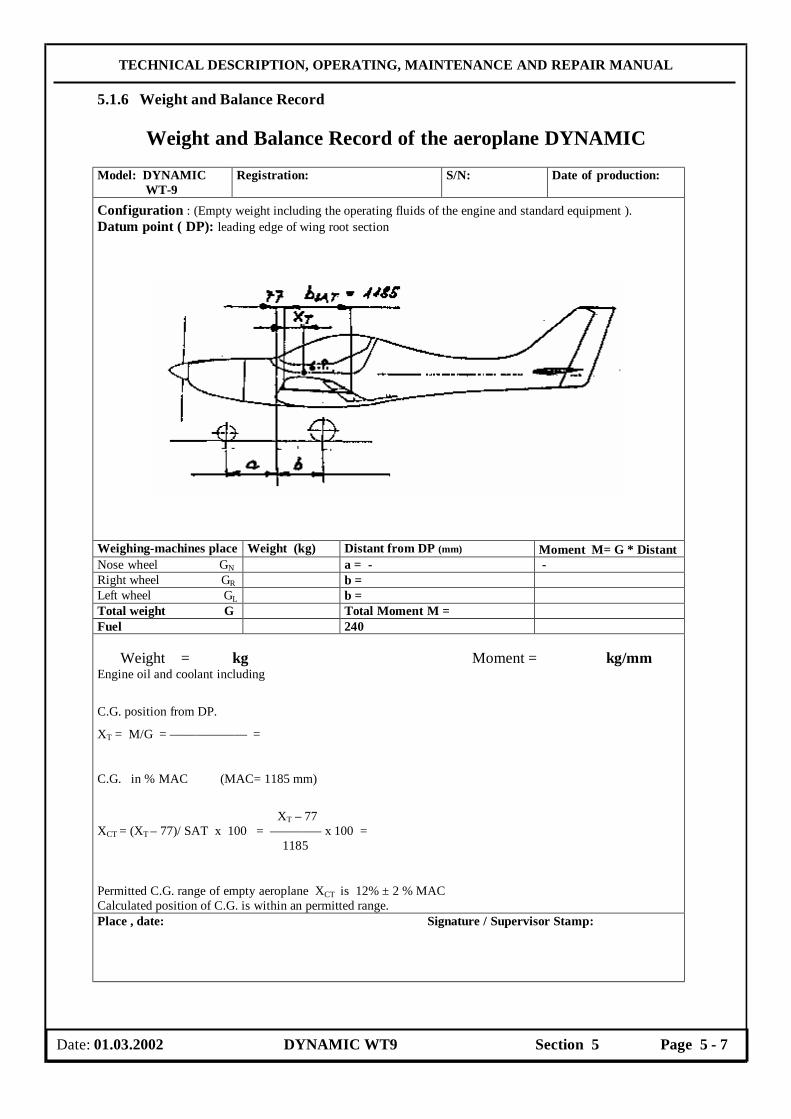
TECHNICAL DESCRIPTION, OPERATING, MAINTENANCE AND REPAIR MANUAL
5.1.6 Weight and Balance Record
Weight and Balance Record of the aeroplane DYNAMIC Model: DYNAMIC WT-9
Registration: S/N: Date of production:
Configuration : (Empty weight including the operating fluids of the engine and standard equipment ). Datum point ( DP): leading edge of wing root section
Weighing-machines place Weight (kg) Distant from DP (mm) Moment M= G ∗ Distant Nose wheel GN a = - - Right wheel GR b = Left wheel GL b = Total weight G Total Moment M = Fuel 240 Weight = kg Moment = kg/mm Engine oil and coolant including
C.G. position from DP.
XT = M/G = –––––––––––– =
C.G. in % MAC (MAC= 1185 mm)
XT – 77 XCT = (XT – 77)/ SAT x 100 = –––––––– x 100 =
1185 Permitted C.G. range of empty aeroplane XCT is 12% ± 2 % MAC Calculated position of C.G. is within an permitted range. Place , date: Signature / Supervisor Stamp:
Date: 01.03.2002 DYNAMIC WT9 Section 5 Page 5 - 7

TECHNICAL DESCRIPTION, OPERATING, MAINTENANCE AND REPAIR MANUAL
5.1.7 Measurement Record – ZKM Encoding Altimeter
MEASUREMENT RECORD – ZKM A/C Type: DYNAMIC WT9 S/N: Registration: Encoding altimeter Type: S/N:
A. Transitions of the encoder (Feet) Transition altitude
Measured error climb
Measured error descent
Allowed toleran.
Code change
Transition altitude
Measured error climb
Measured error descent
Allowed toleran.
Code change
50 50 7950 xx ± 50 750 xx “ B1 8050 xx „ 850 xx „ B1 9950 xx „ 1950 Xx „ 10050 xx „ 2050 xx „ 14750 xx „ A1 2750 “ A4 14850 xx “ A1 2850 xx “ A4 15950 xx “ 3950 Xx “ 16050 xx “ 4050 xx “ 19950 xx “ 4950 Xx “ 20050 xx “ 5050 xx “ 24950 xx “ 5950 Xx “ 25050 xx “ 6050 xx “ 29950 xx “ 6750 Xx “ A2 30050 xx “ 6850 xx A2 34950 Xx 35050 xx
Code change: comply ( yes – no ) B. OTHERS TESTS Tightness test
Allowed tolerance (measure at 4000 feet) is -100 feet
Measured deviation
C. TOTAL ASSESSMENT: comply ( yes – no ) Record elaborated by : Date:
Record approved by : Date:
Measurement carried out by: Date:
Date: 01.03.2002 DYNAMIC WT9 Section 5 Page 5 - 8

TECHNICAL DESCRIPTION, OPERATING, MAINTENANCE AND REPAIR MANUAL
5.1.8 Measurement Record – ZKM Radio Station VHF
Measurement Record
A/C Type: DYNAMIC WT9 S/N: Registration: Radio station VHF S/N: V a l u e Pos. MEASUREMENT Specified Real
1 Check function of the control knobs and the lighting
satisfy
2 Receiver sensitivity f= 118,00 MHz 126,50 MHz 136,95 MHz
3,0 uV
uV uV uV
3 Squelch f= 126,50 MHz satisfy 4 VF Transmitter power f= 118,00 MHz
Ujs - 28,5 V 126,50 MHz 136,95 MHz
7 W
W W W
5 Carrier frequency f=118,00 MHz without modulation 126,50 MHz 136,95 MHz
6 Reflected power f= 118,00 MHz 126,50 MHz 136,95 MHz
satisfy
7 Total assessment satisfy
Record elaborated by: Date:
Record approved by: Date:
Measurement carried out by: Date:
Date: 01.03.2002 DYNAMIC WT9 Section 5 Page 5 - 9

TECHNICAL DESCRIPTION, OPERATING, MAINTENANCE AND REPAIR MANUAL
5.1.9 Measurement Record – ZKM Transponder
Measurement Record A/C Type: DYNAMIC WT9 S/N: Registration: Transponder : S/N: Pos. MEASUREMENT Specified Real
Validity of the Pilot code Satisfy 1 Function of the A/C converter Satisfy
2 Transmitter power Minim.200W 3 Transmitter frequency 1090MHz+3MHz 4 Reply Min. 90%
5 SPI – Duration 25 + 5 sec Impulse position P3 - allowed 0
6
(INTER) - limited Width 0,3 - 0,6 us 7 Width and position F2 - FRAMING Position + 0,15 us
Min.72dBm/90% 8 Sensitivity in Mode - ALT - CODE Min.72dBm/90%
135,95 MHz
% Reply 0% 9 Suppression of the lateral pattern (SLS) – 9 dB Reply 90–100 %
10 Function TEST Satisfy
11 Total assessment Satisfy
Record elaborated by: Date:
Record approved by: Date:
Measurement carried out by: Date:
Date: 01.03.2002 DYNAMIC WT9 Section 5 Page 5 - 10
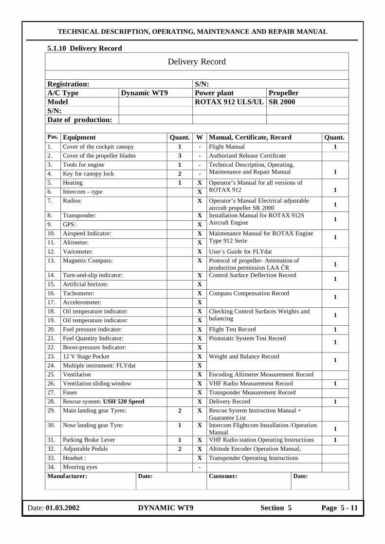
TECHNICAL DESCRIPTION, OPERATING, MAINTENANCE AND REPAIR MANUAL
5.1.10 Delivery Record
Delivery Record Registration: S/N: A/C Type Dynamic WT9 Power plant Propeller Model ROTAX 912 ULS/UL SR 2000 S/N: Date of production: Pos. Equipment Quant. W Manual, Certificate, Record Quant. 1. Cover of the cockpit canopy 1 - Flight Manual 1 2. Cover of the propeller blades 3 - Authorized Release Certificate 3. Tools for engine 1 - 4. Key for canopy lock 2 -
Technical Description, Operating, Maintenance and Repair Manual
1
5. Heating 1 X 6. Intercom – type X
Operator’s Manual for all versions of ROTAX 912
1
7. Radios: X Operator’s Manual Electrical adjustable aircraft propeller SR 2000 1
8. Transponder: X 9. GPS: X
Installation Manual for ROTAX 912S Aircraft Engine 1
10. Airspeed Indicator: X 11. Altimeter: X
Maintenance Manual for ROTAX Engine Type 912 Serie 1
12. Variometer: X User´s Guide for FLYdat 13. Magnetic Compass: X Protocol of propeller- Attestation of
production permission LAA ČR 1
14. Turn-and-slip indicator: X 15. Artificial horizon: X
Control Surface Deflection Record 1
16. Tachometer: X 17. Accelerometer: X
Compass Compensation Record 1
18. Oil temperature indicator: X 19. Oil temperature indicator: X
Checking Control Surfaces Weights and balancing 1
20. Fuel pressure indicator: X Flight Test Record 1 21. Fuel Quantity Indicator: X 22. Boost-pressure Indicator: X
Pitotstatic System Test Record 1
23. 12 V Stage Pocket X 24. Multiple instrument: FLYdat X
Weight and Balance Record 1
25. Ventilation X Encoding Altimeter Measurement Record 26. Ventilation sliding window X VHF Radio Measurement Record 1 27. Fuses X Transponder Measurement Record 28. Rescue system: USH 520 Speed X Delivery Record 1 29. Main landing gear Tyres: 2 X Rescue System Instruction Manual +
Guarantee List
30. Nose landing gear Tyre: 1 X Intercom Flightcom Installation /Operation Manual 1
31. Parking Brake Lever 1 X VHF Radio station Operating Instructions 1 32. Adjustable Pedals 2 X Altitude Encoder Operation Manual, 33. Headset : X Transponder Operating Instructions 34. Mooring eyes - Manufacturer: Date: Customer: Date:
Date: 01.03.2002 DYNAMIC WT9 Section 5 Page 5 - 11

TECHNICAL DESCRIPTION, OPERATING, MAINTENANCE AND REPAIR MANUAL
5.1.11 Aeroplane Wiring diagrams

TECHNICAL DESCRIPTION, OPERATING, MAINTENANCE AND REPAIR MANUAL

TECHNICAL DESCRIPTION, OPERATING, MAINTENANCE AND REPAIR MANUAL

TECHNICAL DESCRIPTION, OPERATING, MAINTENANCE AND REPAIR MANUAL