miwi demo kit user's guide - microchip...
TRANSCRIPT
2012 Microchip Technology Inc. DS70687A
MiWi™ Demo KitUser’s Guide

DS70687A-page 2 2012 Microchip Technology Inc.
Information contained in this publication regarding deviceapplications and the like is provided only for your convenienceand may be superseded by updates. It is your responsibility toensure that your application meets with your specifications.MICROCHIP MAKES NO REPRESENTATIONS ORWARRANTIES OF ANY KIND WHETHER EXPRESS ORIMPLIED, WRITTEN OR ORAL, STATUTORY OROTHERWISE, RELATED TO THE INFORMATION,INCLUDING BUT NOT LIMITED TO ITS CONDITION,QUALITY, PERFORMANCE, MERCHANTABILITY ORFITNESS FOR PURPOSE. Microchip disclaims all liabilityarising from this information and its use. Use of Microchipdevices in life support and/or safety applications is entirely atthe buyer’s risk, and the buyer agrees to defend, indemnify andhold harmless Microchip from any and all damages, claims,suits, or expenses resulting from such use. No licenses areconveyed, implicitly or otherwise, under any Microchipintellectual property rights.
Note the following details of the code protection feature on Microchip devices:
• Microchip products meet the specification contained in their particular Microchip Data Sheet.
• Microchip believes that its family of products is one of the most secure families of its kind on the market today, when used in the intended manner and under normal conditions.
• There are dishonest and possibly illegal methods used to breach the code protection feature. All of these methods, to our knowledge, require using the Microchip products in a manner outside the operating specifications contained in Microchip’s Data Sheets. Most likely, the person doing so is engaged in theft of intellectual property.
• Microchip is willing to work with the customer who is concerned about the integrity of their code.
• Neither Microchip nor any other semiconductor manufacturer can guarantee the security of their code. Code protection does not mean that we are guaranteeing the product as “unbreakable.”
Code protection is constantly evolving. We at Microchip are committed to continuously improving the code protection features of ourproducts. Attempts to break Microchip’s code protection feature may be a violation of the Digital Millennium Copyright Act. If such actsallow unauthorized access to your software or other copyrighted work, you may have a right to sue for relief under that Act.
Microchip received ISO/TS-16949:2009 certification for its worldwide headquarters, design and wafer fabrication facilities in Chandler and Tempe, Arizona; Gresham, Oregon and design centers in California and India. The Company’s quality system processes and procedures are for its PIC® MCUs and dsPIC® DSCs, KEELOQ® code hopping devices, Serial EEPROMs, microperipherals, nonvolatile memory and analog products. In addition, Microchip’s quality system for the design and manufacture of development systems is ISO 9001:2000 certified.
QUALITY MANAGEMENT SYSTEM CERTIFIED BY DNV
== ISO/TS 16949 ==
Trademarks
The Microchip name and logo, the Microchip logo, dsPIC, FlashFlex, KEELOQ, KEELOQ logo, MPLAB, PIC, PICmicro, PICSTART, PIC32 logo, rfPIC, SST, SST Logo, SuperFlash and UNI/O are registered trademarks of Microchip Technology Incorporated in the U.S.A. and other countries.
FilterLab, Hampshire, HI-TECH C, Linear Active Thermistor, MTP, SEEVAL and The Embedded Control Solutions Company are registered trademarks of Microchip Technology Incorporated in the U.S.A.
Silicon Storage Technology is a registered trademark of Microchip Technology Inc. in other countries.
Analog-for-the-Digital Age, Application Maestro, BodyCom, chipKIT, chipKIT logo, CodeGuard, dsPICDEM, dsPICDEM.net, dsPICworks, dsSPEAK, ECAN, ECONOMONITOR, FanSense, HI-TIDE, In-Circuit Serial Programming, ICSP, Mindi, MiWi, MPASM, MPF, MPLAB Certified logo, MPLIB, MPLINK, mTouch, Omniscient Code Generation, PICC, PICC-18, PICDEM, PICDEM.net, PICkit, PICtail, REAL ICE, rfLAB, Select Mode, SQI, Serial Quad I/O, Total Endurance, TSHARC, UniWinDriver, WiperLock, ZENA and Z-Scale are trademarks of Microchip Technology Incorporated in the U.S.A. and other countries.
SQTP is a service mark of Microchip Technology Incorporated in the U.S.A.
GestIC and ULPP are registered trademarks of Microchip Technology Germany II GmbH & Co. & KG, a subsidiary of Microchip Technology Inc., in other countries.
All other trademarks mentioned herein are property of their respective companies.
© 2012, Microchip Technology Incorporated, Printed in the U.S.A., All Rights Reserved.
Printed on recycled paper.
ISBN: 978-1-62076-575-3
MiWi™ DEMO KITUSER’S GUIDE
Table of Contents
Preface ........................................................................................................................... 5
Chapter 1. Overview1.1 MiWi™ Demo Kit Contents ............................................................................. 91.2 MiWi™ Demo Kit ............................................................................................ 9
Chapter 2. MiWi™ Demo Board2.1 MiWi™ Board Layout and Features ............................................................. 11
Chapter 3. Getting Started3.1 Hardware Requirements .............................................................................. 153.2 Demo Setup ................................................................................................. 153.3 Preprogrammed Tutorial Operation .............................................................. 15
Appendix A. MiWi™ Demo Board SchematicsA.1 Introduction .................................................................................................. 19A.2 MiWi™ Demo Board Schematics ................................................................. 19A.3 MiWi™ Demo Board PCB Layout ................................................................ 23A.4 MiWi™ Demo Board Bill of Materials (BOM) ............................................... 29
Index ............................................................................................................................. 31
Worldwide Sales and Service .................................................................................... 32
2012 Microchip Technology Inc. DS70687A-page 3
NOTES:
2012 Microchip Technology Inc. DS70687A-page 4

MiWi™ DEMO KIT
USER’S GUIDEPreface
INTRODUCTION
This chapter contains general information that will be useful to know before using the MiWi™ Demo Kit User’s Guide. Items discussed in this chapter include:
• Document Layout• Conventions Used in this Guide• Warranty Registration
• Recommended Reading• The Microchip Web Site• Development Systems Customer Change Notification Service• Customer Support
DOCUMENT LAYOUT
This user’s guide describes how to use the MiWi Demo Kit to evaluate and experiment the Microchip Wireless Solutions. This user’s guide consists of the following chapters:
• Chapter 1. “Overview” This chapter describes the MiWi Demo Kit and how it works.
• Chapter 2. “MiWi™ Demo Board” This chapter details the hardware information of the MiWi Demo Board.
• Chapter 3. “Getting Started” This chapter describes what you need to know to start using the MiWi Demo Kit.
• Appendix A. “MiWi™ Demo Board Schematics” This appendix illustrates the PCB layout and BOM, and it also includes MiWi Demo Board schematics.
NOTICE TO CUSTOMERS
All documentation becomes dated, and this manual is no exception. Microchip tools and documentation are constantly evolving to meet customer needs, so some actual dialogs and/or tool descriptions may differ from those in this document. Please refer to our web site (www.microchip.com) to obtain the latest documentation available.
Documents are identified with a “DS” number. This number is located on the bottom of each page, in front of the page number. The numbering convention for the DS number is “DSXXXXXA”, where “XXXXX” is the document number and “A” is the revision level of the document.
For the most up-to-date information on development tools, see the MPLAB® IDE online help. Select the Help menu, and then Topics to open a list of available online help files.
2012 Microchip Technology Inc. DS70687A-page 5

MiWi™ Demo Kit User’s Guide
CONVENTIONS USED IN THIS GUIDE
This manual uses the following documentation conventions:
DOCUMENTATION CONVENTIONS
Description Represents Examples
Arial font:
Italic characters Referenced books MPLAB® IDE User’s Guide
Emphasized text ...is the only compiler...
Initial caps A window the Output window
A dialog the Settings dialog
A menu selection select Enable Programmer
Quotes A field name in a window or dialog “Save project before build”
Underlined, italic text with right angle bracket
A menu path File>Save
Bold characters A dialog button Click OK
A tab Click the Power tab
Text in angle brackets < > A key on the keyboard Press <Enter>, <F1>
Courier New font:
Plain Courier New Sample source code #define START
Filenames autoexec.bat
File paths C:\mcc18\h
Keywords _asm, _endasm, static
Command-line options -Opa+, -Opa-
Bit values 0, 1
Constants (in source code) 0xFF, ‘A’
Italic Courier New A variable argument file.o, where file can be any valid filename
Square brackets [ ] Optional arguments mcc18 [options] file [options]
Curly brackets and pipe character: { | }
Choice of mutually exclusive arguments; an OR selection
errorlevel {0|1}
Ellipses... Replaces repeated text var_name [, var_name...]
Represents code supplied by user void main (void){ ...}
DS70687A-page 6 2012 Microchip Technology Inc.
Preface
WARRANTY REGISTRATION
Please complete the enclosed Warranty Registration Card and mail it promptly. Sending in the Warranty Registration Card entitles users to receive new product updates. Interim software releases are available at the Microchip web site.
RECOMMENDED READING
This user's guide describes how to use the ZENA Wireless Adapter. The following Microchip documents are available from the Microchip web site (http://www.micro-chip.com), and are recommended as supplemental reference resources.
• “MRF24J40MA 2.4 GHz IEEE Std. 802.15.4 RF Transceiver Module” (DS70329)
• “MRF89XAM8A Data Sheet 868 MHz Ultra-Low Power Sub-GHz Transceiver Module” (DS70651)
• “MRF89XAM9A Data Sheet 915 MHz Ultra-Low Power Sub-GHz Transceiver Module” (DS75017)
• “PIC18F46J50 USB Microcontroller Data Sheet” (DS39931)
• “2K SPI Bus Serial EEPROM with EUI-48TM Node Identity Data Sheet” (DS22123)
• “1 Mbit SPI Serial Flash SST25VF010A” (S725081)
• “MCP9700A/01A - Low Power Linear Active Thermistor ICs” (DS21942)
THE MICROCHIP WEB SITE
Microchip provides online support through our web site at http://www.microchip.com. This web site makes files and information easily available to customers. Accessible by most Internet browsers, the web site contains the following information:
• Product Support – Data sheets and errata, application notes and sample programs, design resources, user’s guides and hardware support documents, latest software releases and archived software
• General Technical Support – Frequently Asked Questions (FAQs), technical support requests, online discussion groups, Microchip consultant program member listings
• Business of Microchip – Product selector and ordering guides, latest Microchip press releases, listings of seminars and events; and listings of Microchip sales offices, distributors and factory representatives
2012 Microchip Technology Inc. DS70687A-page 7
MiWi™ Demo Kit User’s Guide
DEVELOPMENT SYSTEMS CUSTOMER CHANGE NOTIFICATION SERVICE
Microchip’s customer notification service helps keep customers current on Microchip products. Subscribers will receive e-mail notification whenever there are changes, updates, revisions or errata related to a specified product family or development tool of interest.
To register, access the Microchip web site at http://www.microchip.com, click Customer Change Notification and follow the registration instructions.
The Development Systems product group categories are:
• Compilers – The latest information on Microchip C compilers and other language tools. These include the MPLAB C18 and MPLAB C30 C compilers; MPASM™ and MPLAB ASM30 assemblers; MPLINK™ and MPLAB LINK30 object linkers; and MPLIB™ and MPLAB LIB30 object librarians.
• Emulators – The latest information on Microchip in-circuit emulators. This includes the MPLAB ICE 2000 and MPLAB ICE 4000.
• In-Circuit Debuggers – The latest information on the Microchip in-circuit debugger, MPLAB ICD 2.
• MPLAB IDE – The latest information on Microchip MPLAB IDE, the Windows® Integrated Development Environment for development systems tools. This list is focused on the MPLAB IDE, MPLAB SIM simulator, MPLAB IDE Project Manager and general editing and debugging features.
• Programmers – The latest information on Microchip programmers. These include the MPLAB PM3 and PRO MATE® II device programmers and the PICSTART® Plus and PICkit™ 1 development programmers.
CUSTOMER SUPPORT
Several channels are available to assist the users of Microchip products:
• Distributor or Representative
• Local Sales Office
• Field Application Engineer (FAE)
• Technical Support
Customers should contact their distributor, representative, or FAE for support. Local sales offices are also available to help customers. A list of sales offices and locations is included in the back of this document.
Technical support is available through our web site at http://support.microchip.com.
DOCUMENT REVISION HISTORY
Revision A (September 2012)
This is the initial released version of the document.
DS70687A-page 8 2012 Microchip Technology Inc.
MiWi™ DEMO KIT
USER’S GUIDEChapter 1. Overview
This chapter introduces the MiWi™ Demo Kit features and its requirements. The topic covered includes:
• MiWi™ Demo Kit Contents
• MiWi™ Demo Kit
1.1 MiWi™ DEMO KIT CONTENTS
Based on the frequency of operation selected, the MiWi Demo Kit contains any one of the following items:
• Two MiWi Demo Boards with PIC18F46J50 XLP Microcontroller with MRF24J40 MA Module
• Two MiWi Demo Boards with PIC18F46J50 XLP Microcontroller with MRF89XAM8A Module
• Two MiWi Demo Boards with PIC18F46J50 XLP Microcontroller with MRF89XAM9A Module
1.2 MiWi™ DEMO KIT
The MiWi Demo Kit enables developers to evaluate and experiment with 2.4 GHz, 868 MHz and 915 MHz RF solutions from Microchip. The MiWi Demo Kit contains two hardware nodes (MiWi Demo Boards) which can be used to create a simple two node MiWi wireless network. More hardware nodes to the same network can be added by purchasing additional MiWi Demo Kits or individual components.
The MiWi Demo Kit is preprogrammed with a wireless demo program that enables users to setup a MiWi network easily. For more information on running the preprogrammed demo program and extending the network refer to Chapter 3.“Getting Started”. The Microchip wireless stacks and additional application demo source codes can be downloaded from the Microchip web site http://www.microchip.com/wireless.
2012 Microchip Technology Inc. DS70687A-page 9
MiWi™ Demo Kit User’s Guide
NOTES:
DS70687A-page 10 2012 Microchip Technology Inc.
MiWi™ DEMO KIT
USER’S GUIDEChapter 2. MiWi™ Demo Board
This chapter describes the MiWi Demo Board hardware and the topic covers MiWi™ Board Layout and Features.
2.1 MiWi™ BOARD LAYOUT AND FEATURES
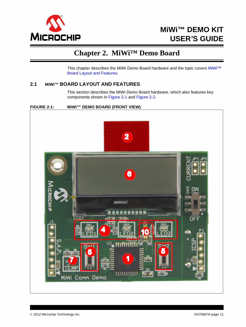
This section describes the MiWi Demo Board hardware, which also features key components shown in Figure 2-1 and Figure 2-2.
FIGURE 2-1: MiWi™ DEMO BOARD (FRONT VIEW)
2012 Microchip Technology Inc. DS70687A-page 11
MiWi™ Demo Kit User’s Guide
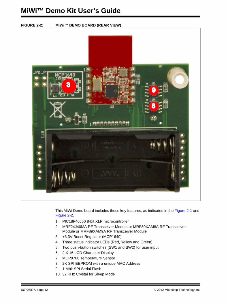
FIGURE 2-2: MiWi™ DEMO BOARD (REAR VIEW)
This MiWi Demo board includes these key features, as indicated in the Figure 2-1 and Figure 2-2.
1. PIC18F46J50 8-bit XLP microcontroller
2. MRF24J40MA RF Transceiver Module or MRF89XAM8A RF Transceiver Module or MRF89XAM9A RF Transceiver Module
3. +3.3V Boost Regulator (MCP1640)
4. Three status indicator LEDs (Red, Yellow and Green)
5. Two push-button switches (SW1 and SW2) for user input
6. 2 X 16 LCD Character Display
7. MCP9700 Temperature Sensor
8. 2K SPI EEPROM with a unique MAC Address
9. 1 Mbit SPI Serial Flash
10. 32 KHz Crystal for Sleep Mode
DS70687A-page 12 2012 Microchip Technology Inc.
MiWi™ Demo Board
Some of main blocks defined on the board are explained in detail below:
2.1.1 PIC18F46J50 Microcontroller
PIC18F46J50 microcontroller is an 8-bit XLP 44-pin microcontroller with 64K program memory.
2.1.2 RF Transceiver Module
MiWi Demo board supports MRF24J40MA, MRF89XAM8A, MRF89XAM9A RF transceiver modules. It has dedicated SPI Interface and interrupt lines between the microcontroller and the RF transceiver module.
2.1.3 Status Indicator LEDs
To indicate the status the MiWi Demo board has three LEDs: LED1(green), LED2 (yellow), and LED3 (red).
2.1.4 Push Buttons
MiWi Demo board contains two push buttons SW1 and SW2. These push buttons are assigned to the individual interrupt lines of the microcontroller. The user software must enable Port B pull-ups of the microcontroller before evaluating the push button state. Example 2-1provides a possible solution to evaluate the state of SW1 push button.
EXAMPLE 2-1: CODE EXAMPLE FOR EVALUATING THE STATE OF SW1
2.1.5 LCD Character Display
The LCD supports power saving modes. The LCD has a backlight display which can be turned on or off based on the power consumption and it supports 32 characters in two lines (16 characters in each line). It uses shared SPI interface (with SPI EEPROM and SPI Serial Flash) to communicate with the microcontroller.
2.1.6 Temperature Sensor
The temperature sensor (MCP9700A) is a low-power Linear Active Thermistor IC. To minimize power consumption, the sensor is powered from a port pin. After powering up, the sensor output can be measured after a minute. The internal AD converter of the microcontroller can be used to measure the temperature value.
// Initialize RB1 - SW1
TRISBbits.TRISB2 = 1;// RB1 is an input
ANCON1 = ANCON1 | 0x04;// RB1 is a digital pin
/*
User Code
*/
//Evaluating RB1
INTCON2bits.RBPU = 0;// Enable PORT B pull-ups for switches
If (PORTBbits.RB1 = 0 )// RB1 pushed
{
/*
RB1/SW1 push button code
*/
}
INTCON2bits.RBPU = 1;//PORTB pull-ups disabled
2012 Microchip Technology Inc. DS70687A-page 13
MiWi™ Demo Kit User’s Guide
2.1.7 EEPROM with MAC Address
The Serial EEPROM is a low-power, Microchip 25LC256 256K SPI Bus Serial EEPROM, it uses shared SPI interface with SPI Serial Flash and LCD.
2.1.8 SPI Serial Flash
MiWi Demo board features a 1Mb SPI Serial Flash for storing and retrieving network or any application specific information. The SPI Serial Flash and Serial EEPROM share the SPI bus and each has its own active low-chip select.
2.1.9 Power Supply
The MiWi Demo board uses two AAA batteries for power supply. Current consumption for the entire board can also be measured at JP1 and JP2 without disturbing it.
2.1.10 +3.3V Boost Regulator
The MCP1640 is a compact, high efficiency boost regulator. It ensures that the voltage requirements for the RF transceivers are met throughout the lifetime of the battery.
DS70687A-page 14 2012 Microchip Technology Inc.

MiWi™ DEMO KIT
USER’S GUIDEChapter 3. Getting Started
This chapter is a self paced tutorial to use the MiWi™ Demo Board. It explains in detail how to run the preprogrammed demo. The source code for the demo is available along with the MiWi stack (latest version of Microchip Applications library is available at http://www.microchip.com/MAL). After unzipping the latest version of MiWi stack, the default location for MiWi Demo Kit Out of Box Demo is "C:\Microchip Solutions\MiWi DE Demo\MiWi Demo Kit\".
For more information about MiWi stack, refer to http:// www.microchip.com/MiWi.
Topics covered include:
• Hardware Requirements
• Demo Setup
• Preprogrammed Tutorial Operation
3.1 HARDWARE REQUIREMENTS
The following hardware is required to run the preprogrammed demo application:
• Two MiWi Demo Boards
• Four AAA batteries for powering up the boards
3.2 DEMO SETUP
The MiWi Demo Board comes with a preprogrammed Demo Board. Follow these steps to set up the demo:
1. Plug in two AAA batteries on each MiWi Demo Board.
2. To power up the board, move SW3 switch from “OFF” position to the “ON” position. On powering, a splash screen will be displayed on the LCD screen.
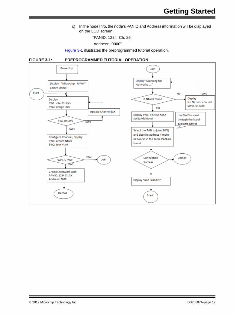
3.3 PREPROGRAMMED TUTORIAL OPERATION
1. On powering the boards, the following splash screen message will be displayed on the LCD screen for 2 seconds.
“Microchip
MiWi Demo Board”
2. The display changes to channel selection screen. Choose the channel to setup the network.
“SW1: <Sel Ch: 26>
SW2: Chnge Chnl”
2012 Microchip Technology Inc. DS70687A-page 15
MiWi™ Demo Kit User’s Guide
Press SW1 push button to select channel 26 as the operating channel or press SW2 push button to choose a different channel. For MRF24J40 Channel 11 through channel 26 are available. Using the push buttons on the board, the user can choose operating channel from channel 11 through channel 26. For MRF89XA channel 0 through channel 31 are available.
3. The LCD screen displays network setup options:
“SW1: Create Ntwk
SW2: Join Ntwk”
4. Press SW1 push button on one of the boards to create a MiWi network (PAN Coordinator) with a random PANID. After the network is created, the board will notify the user that the network is created successfully, and then display the node information such as PAN ID, Channel and Address until a node joins.
“PANID: 1234 Ch: 26
Address: 0000”
5. Press SW2 push button on the second board to join a MiWi network. The board performs a scan of nearby networks and allows the user to choose the network to join to.
“SW1: < PANID:1234>
SW2: Additional”
6. Press SW1 push button on the second board after choosing the network (PANID) to connect.
7. After the second board is joined the network, the user has the option to run any one of the these demo applications: Range Demo, Temp Demo, Node Info. The LCD screen displays this message.
“SW1: Range Demo
SW2: Other Apps”
The current Out of Box demo for MiWi Demo Kit supports all the three Range Demo, Temp Demo and Node Info applications.
a) Range Demo is used to demonstrate the range of Microchip’s MRF24J40MA and MRF89XA transceiver. It performs a range test by transmitting a packet to the remote node and displaying the Received Signal Strength Indication (RSSI) value on the LCD Display. The display will show this RSSI value after each packet is received and will notify the user the strength of the signal such as, high, medium, low, or out of range.
b) The Temp Demo uses on-board Microchip’s MCP9700A temperature sensor (Low-Power Linear Active Thermistor IC). This demo measures the temperature and displays its local temperature information in C (Celsius) and F (Fahrenheit) on the display and broadcast its reading to other nodes listening. If other nodes are connected it will then cycle through each remote node’s reading.
Note: Ensure that you select same operating channel on both the MiWi Demo Boards to enable connection with each other.
Note: If more than one node from the same network (PANID) has responded with a beacon, the user can select the node to join by using the network short address information printed on the LCD. Use SW1 and SW2 to choose the node to establish connection with in a network similar to PANID.
DS70687A-page 16 2012 Microchip Technology Inc.
Getting Started
c) In the node Info, the node’s PANID and Address information will be displayed on the LCD screen.
“PANID: 1234 Ch: 26
Address: 0000”
Figure 3-1 illustrates the preprogrammed tutorial operation.
FIGURE 3-1: PREPROGRAMMED TUTORIAL OPERATION
2012 Microchip Technology Inc. DS70687A-page 17

MiWi™ Demo Kit User’s Guide
NOTES:
DS70687A-page 18 2012 Microchip Technology Inc.
MiWi™ DEMO KIT
USER’S GUIDEAppendix A. MiWi™ Demo Board Schematics
A.1 INTRODUCTION
This appendix includes:
• MiWi™ Demo Board Schematics
• MiWi™ Demo Board PCB Layout
• MiWi™ Demo Board Bill of Materials (BOM)
A.2 MiWi™ DEMO BOARD SCHEMATICS
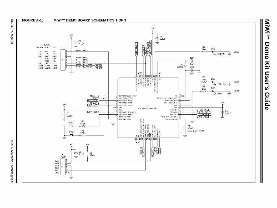
Figure A-1, Figure A-2 and Figure A-3 illustrate the MiWi Demo Board schematics.
2012 Microchip Technology Inc. DS70687A-page 19
MiW
i™ D
emo
Kit U
ser’s Gu
ide
DS
70687A-page 20
2012 M
icrochip Technolo
gy Inc.
FIGURE A-1: MiWi™ DEMO BOARD SCHEMATICS 1 OF 3

Ap
pen
dix A
2012
Microchip T
echnology Inc.D
S70687A
-page 21
F
IGURE A-2: MiWi™ DEMO BOARD SCHEMATICS 2 OF 3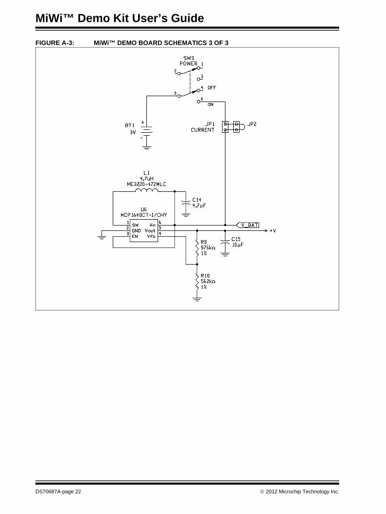
MiWi™ Demo Kit User’s Guide
FIGURE A-3: MiWi™ DEMO BOARD SCHEMATICS 3 OF 3
DS70687A-page 22 2012 Microchip Technology Inc.
Appendix A
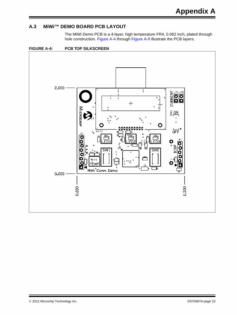
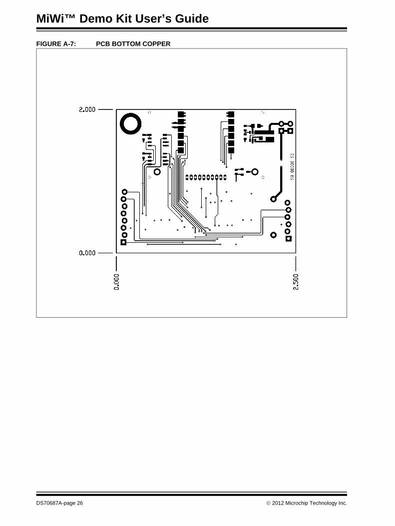
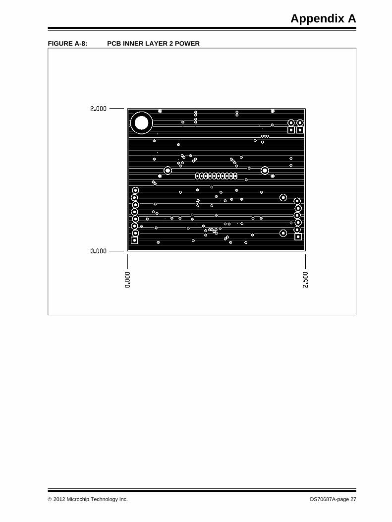
A.3 MiWi™ DEMO BOARD PCB LAYOUT
The MiWi Demo PCB is a 4-layer, high temperature FR4, 0.062 inch, plated through hole construction. Figure A-4 through Figure A-9 illustrate the PCB layers.
FIGURE A-4: PCB TOP SILKSCREEN
2012 Microchip Technology Inc. DS70687A-page 23

MiWi™ Demo Kit User’s Guide
FIGURE A-5: PCB TOP COPPER
DS70687A-page 24 2012 Microchip Technology Inc.

Appendix A
FIGURE A-6: PCB BOTTOM SILKSCREEN
2012 Microchip Technology Inc. DS70687A-page 25
MiWi™ Demo Kit User’s Guide
FIGURE A-7: PCB BOTTOM COPPER
DS70687A-page 26 2012 Microchip Technology Inc.
Appendix A
FIGURE A-8: PCB INNER LAYER 2 POWER
2012 Microchip Technology Inc. DS70687A-page 27

MiWi™ Demo Kit User’s Guide
FIGURE A-9: PCB INNER LAYER 3 GROUND
DS70687A-page 28 2012 Microchip Technology Inc.
Appendix A
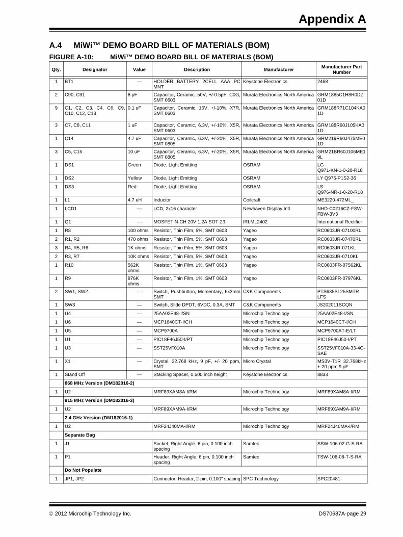
A.4 MiWi™ DEMO BOARD BILL OF MATERIALS (BOM)FIGURE A-10: MiWi™ DEMO BOARD BILL OF MATERIALS (BOM)
Qty. Designator Value Description ManufacturerManufacturer Part
Number
1 BT1 — HOLDER BATTERY 2CELL AAA PCMNT
Keystone Electronics 2468
2 C90, C91 8 pF Capacitor, Ceramic, 50V, +/-0.5pF, C0G,SMT 0603
Murata Electronics North America GRM1885C1H8R0DZ01D
9 C1, C2, C3, C4, C6, C9,C10, C12, C13
0.1 uF Capacitor, Ceramic, 16V, +/-10%, X7R,SMT 0603
Murata Electronics North America GRM188R71C104KA01D
3 C7, C8, C11 1 uF Capacitor, Ceramic, 6.3V, +/-10%, X5R,SMT 0603
Murata Electronics North America GRM188R60J105KA01D
1 C14 4.7 uF Capacitor, Ceramic, 6.3V, +/-20%, X5R,SMT 0805
Murata Electronics North America GRM219R60J475ME01D
3 C5, C15 10 uF Capacitor, Ceramic, 6.3V, +/-20%, X5R,SMT 0805
Murata Electronics North America GRM21BR60J106ME19L
1 DS1 Green Diode, Light Emitting OSRAM LGQ971-KN-1-0-20-R18
1 DS2 Yellow Diode, Light Emitting OSRAM LY Q976-P1S2-36
1 DS3 Red Diode, Light Emitting OSRAM LSQ976-NR-1-0-20-R18
1 L1 4.7 uH Inductor Coilcraft ME3220-472ML_
1 LCD1 — LCD, 2x16 character Newhaven Display Intl NHD-C0216CZ-FSW-FBW-3V3
1 Q1 — MOSFET N-CH 20V 1.2A SOT-23 IRLML2402 International Rectifier
1 R8 100 ohms Resistor, Thin Film, 5%, SMT 0603 Yageo RC0603JR-07100RL
2 R1, R2 470 ohms Resistor, Thin Film, 5%, SMT 0603 Yageo RC0603JR-07470RL
3 R4, R5, R6 1K ohms Resistor, Thin Film, 5%, SMT 0603 Yageo RC0603JR-071KL
2 R3, R7 10K ohms Resistor, Thin Film, 5%, SMT 0603 Yageo RC0603JR-0710KL
1 R10 562K ohms
Resistor, Thin Film, 1%, SMT 0603 Yageo RC0603FR-07562KL
1 R9 976K ohms
Resistor, Thin Film, 1%, SMT 0603 Yageo RC0603FR-07976KL
2 SW1, SW2 — Switch, Pushbutton, Momentary, 6x3mmSMT
C&K Components PTS635SL25SMTRLFS
1 SW3 — Switch, Slide DPDT, 6VDC, 0.3A, SMT C&K Components JS202011SCQN
1 U4 — 25AA02E48-I/SN Microchip Technology 25AA02E48-I/SN
1 U6 — MCP1640CT-I/CH Microchip Technology MCP1640CT-I/CH
1 U5 — MCP9700A Microchip Technology MCP9700AT-E/LT
1 U1 — PIC18F46J50-I/PT Microchip Technology PIC18F46J50-I/PT
1 U3 — SST25VF010A Microchip Technology SST25VF010A-33-4C-SAE
1 X1 — Crystal, 32.768 kHz, 9 pF, +/- 20 ppm,SMT
Micro Crystal MS3V-T1R 32.768kHz+-20 ppm 9 pF
1 Stand Off — Stacking Spacer, 0.500 inch height Keystone Electronics 8833
868 MHz Version (DM182016-2)
1 U2 MRF89XAM8A-I/RM Microchip Technology MRF89XAM8A-I/RM
915 MHz Version (DM182016-3)
1 U2 MRF89XAM9A-I/RM Microchip Technology MRF89XAM9A-I/RM
2.4 GHz Version (DM182016-1)
1 U2 MRF24J40MA-I/RM Microchip Technology MRF24J40MA-I/RM
Separate Bag
1 J1 Socket, Right Angle, 6 pin, 0.100 inch spacing
Samtec SSW-106-02-G-S-RA
1 P1 Header, Right Angle, 6 pin, 0.100 inch spacing
Samtec TSW-106-08-T-S-RA
Do Not Populate
1 JP1, JP2 Connector, Header, 2-pin, 0.100" spacing SPC Technology SPC20481
2012 Microchip Technology Inc. DS70687A-page 29

MiWi™ Demo Kit User’s Guide
NOTES:
DS70687A-page 30 2012 Microchip Technology Inc.
MiWi™ DEMO KITUSER’S GUIDE
2012 Microchip Technology Inc. DS70687A-page 31
BBlock Diagrams
High-level ......................................................... 23
CCustomer Change Notification Service ..................... 7Customer Support ..................................................... 7
DDocumentation
Conventions ....................................................... 5
IInternet Address ........................................................ 6
MMicrochip Internet Web Site ...................................... 6
RReadme .................................................................... 6
SSchematics
Solomon Systech SSD1926 LCD Controller 29
WWWW Address .......................................................... 6
Index
DS70687A-page 32 2012 Microchip Technology Inc.
AMERICASCorporate Office2355 West Chandler Blvd.Chandler, AZ 85224-6199Tel: 480-792-7200 Fax: 480-792-7277Technical Support: http://www.microchip.com/supportWeb Address: www.microchip.com
AtlantaDuluth, GA Tel: 678-957-9614 Fax: 678-957-1455
BostonWestborough, MA Tel: 774-760-0087 Fax: 774-760-0088
ChicagoItasca, IL Tel: 630-285-0071 Fax: 630-285-0075
ClevelandIndependence, OH Tel: 216-447-0464 Fax: 216-447-0643
DallasAddison, TX Tel: 972-818-7423 Fax: 972-818-2924
DetroitFarmington Hills, MI Tel: 248-538-2250Fax: 248-538-2260
IndianapolisNoblesville, IN Tel: 317-773-8323Fax: 317-773-5453
Los AngelesMission Viejo, CA Tel: 949-462-9523 Fax: 949-462-9608
Santa ClaraSanta Clara, CA Tel: 408-961-6444Fax: 408-961-6445
TorontoMississauga, Ontario, CanadaTel: 905-673-0699 Fax: 905-673-6509
ASIA/PACIFICAsia Pacific OfficeSuites 3707-14, 37th FloorTower 6, The GatewayHarbour City, KowloonHong KongTel: 852-2401-1200Fax: 852-2401-3431
Australia - SydneyTel: 61-2-9868-6733Fax: 61-2-9868-6755
China - BeijingTel: 86-10-8569-7000 Fax: 86-10-8528-2104
China - ChengduTel: 86-28-8665-5511Fax: 86-28-8665-7889
China - ChongqingTel: 86-23-8980-9588Fax: 86-23-8980-9500
China - HangzhouTel: 86-571-2819-3187 Fax: 86-571-2819-3189
China - Hong Kong SARTel: 852-2401-1200 Fax: 852-2401-3431
China - NanjingTel: 86-25-8473-2460Fax: 86-25-8473-2470
China - QingdaoTel: 86-532-8502-7355Fax: 86-532-8502-7205
China - ShanghaiTel: 86-21-5407-5533 Fax: 86-21-5407-5066
China - ShenyangTel: 86-24-2334-2829Fax: 86-24-2334-2393
China - ShenzhenTel: 86-755-8203-2660 Fax: 86-755-8203-1760
China - WuhanTel: 86-27-5980-5300Fax: 86-27-5980-5118
China - XianTel: 86-29-8833-7252Fax: 86-29-8833-7256
China - XiamenTel: 86-592-2388138 Fax: 86-592-2388130
China - ZhuhaiTel: 86-756-3210040 Fax: 86-756-3210049
ASIA/PACIFICIndia - BangaloreTel: 91-80-3090-4444 Fax: 91-80-3090-4123
India - New DelhiTel: 91-11-4160-8631Fax: 91-11-4160-8632
India - PuneTel: 91-20-2566-1512Fax: 91-20-2566-1513
Japan - OsakaTel: 81-66-152-7160 Fax: 81-66-152-9310
Japan - YokohamaTel: 81-45-471- 6166 Fax: 81-45-471-6122
Korea - DaeguTel: 82-53-744-4301Fax: 82-53-744-4302
Korea - SeoulTel: 82-2-554-7200Fax: 82-2-558-5932 or 82-2-558-5934
Malaysia - Kuala LumpurTel: 60-3-6201-9857Fax: 60-3-6201-9859
Malaysia - PenangTel: 60-4-227-8870Fax: 60-4-227-4068
Philippines - ManilaTel: 63-2-634-9065Fax: 63-2-634-9069
SingaporeTel: 65-6334-8870Fax: 65-6334-8850
Taiwan - Hsin ChuTel: 886-3-5778-366Fax: 886-3-5770-955
Taiwan - KaohsiungTel: 886-7-536-4818Fax: 886-7-330-9305
Taiwan - TaipeiTel: 886-2-2500-6610 Fax: 886-2-2508-0102
Thailand - BangkokTel: 66-2-694-1351Fax: 66-2-694-1350
EUROPEAustria - WelsTel: 43-7242-2244-39Fax: 43-7242-2244-393Denmark - CopenhagenTel: 45-4450-2828 Fax: 45-4485-2829
France - ParisTel: 33-1-69-53-63-20 Fax: 33-1-69-30-90-79
Germany - MunichTel: 49-89-627-144-0 Fax: 49-89-627-144-44
Italy - Milan Tel: 39-0331-742611 Fax: 39-0331-466781
Netherlands - DrunenTel: 31-416-690399 Fax: 31-416-690340
Spain - MadridTel: 34-91-708-08-90Fax: 34-91-708-08-91
UK - WokinghamTel: 44-118-921-5869Fax: 44-118-921-5820
Worldwide Sales and Service
11/29/11