mitsubishi - superior sewing machine & supply llc lt… · · 2016-09-29mitsubishi industrial...
TRANSCRIPT

MITSUBISHIIndustrial Sewing MachineTechnical information
Model LT2-250(Auto-changer)
Double-NeedleLockstitch, Needle Feed,Automatic Corner-StitchingMachine withAutomatic Undertrimmer
ET-020A
MITSUBIELECTRiCA MITSUBiSHI
From the library of: Superior Sewing Machine & Supply LLC

CONTENTS -
Specifications
Name of major parts 2
1 Sewing machine head 32 Electricals 3
Preparation for operation
• Construction of sewing machine, motor, and control panel 41 Threading with needle thread 42 Adjustment of lubrication to thread take up lever 43 Installation of solenoid-driven presser foot lifter and knee switch 54 Installation of control panel 7
5 External wiring 76 Setting of DIP switches in the control box 77 Power cable connection 8
8 Adjustment of needle bar stop position 8
Operation for automatic corner stitching
1 Setting of switches and counters on the control panel 92 Retracing of corner stitching step 103 Continuous single-needle stitching 104 Compensation stitching 10
5 Example of corner stitching patterns 106 Stitching procedure 11
Automatic corner stitching Special operation procedure
1 Corner stitching Knee switch operation 122 Corner stitching Shallow pedal heeling operation 13
How to use the sewing machine head
1 Needle bar changing mechanism 14
2 Others 14
Setting the DIP switches in control panel 14
How to use the control box
1 "1—2 POSITION" select switch operations 15
2 Adjusting the maximum stitching speed 153 Optional function 16
4 Adjusting the pedaling forces 18
Troubleshooting table 19
From the library of: Superior Sewing Machine & Supply LLC

SPECIFICATIONS
•Sewing machine head
Model LT2-250-M1ATW LT2-250-A1AT LT2-250-B1AT
Application Light to medium-heavy Medium-heavy Medium-heavy to heavy
Max. speed spm 3,500 3,000 3,000 3,000 2,500
Stitch length mm (inch) 4 (5/32) 5 (3/16) 5 (3/16) 6 (15/64) 7 (9/32)
Presser foot strokeAutomatic/manual mm (inch)
9/7 (11/32 / 9/32)
Needle
DP X 5 #14,135 X 5 #14,134 Nm 90
DP X 5 #16,135 X 5 #16,134 Nm 100
DP X 5 #18,135 X 5 #18,134 Nm 110
Hook(for thread trimmer use)
Horizontal type standardhook with bobbincase(with thread slack prevention spring)
Horizontal type large-sized hook with bobbincase(with thread slack prevention spring)
Bobbin Aluminum bobbin for thread trimmer use
Lubrication system Automatic lubrication
Compensation sewing Provided
Touchback Provided
Wiper Provided Not provided
Needle gauge mm (inch) Standard-6.4 (1/4), Optional-3.2.4.8, 8, 9.5,12.7 (1/8,3/16, 5/16, 3/8,1/2)
Note: • For feed dog, throat plate, slider plate, bobbin case and bobbin, use those for thread trimmerapplication.
• Bobbin should be of good quality that is not deformed.
•Applicable Equipment
Table TLT-A353-T3TLT-A363-T3
TLT-B353-T3TLT-B363-T3
Motor CA-Z402E CB-Z402E
Control box LE-MDF
•Auto-Changer Kit
ModelLE-CNA-KM(Standard)
LE-CNA-KA(Option)
Automaticpresser footlifter
LE-FM-2(Electromagnetic type)
LE-FA(Pneumatictype)
Control panel LE-CNA
Knee switch LE-FM-CFT
•Control Panel
Model LE-CNA
Backtacking 4-dial system (Oto 9 stitches),start and end
Number ofcorner-stitching steps
Max. 8
Number ofcorner stitches
0 to 9 stitches
Process return Possible
Continuoussingle-needlestitching
Possible for right andleft needles
-1-
From the library of: Superior Sewing Machine & Supply LLC

NAME OF MAJOR PARTS
1. Sewing machine head
(D d)® (D)®®® ®(!l)® ®® @
17 Arm shaft
18 Timing belt pulley (upper)
19 Timing belt
20 Balance wheel
21 Synchronizer
22 Arm
23 Reverse-stitch lever
24 Stitch length adjusting dial
25 Reverse-stitch solenoid
26 Timing belt pulley (lower)
27 Lubricator
1 Solenoid cover 17 Arm si
2 Needle selection solenoid 18 Timini
3 Lever (left) 19 Timing
4 Lever (right) 20 Balanc
5 Cam (left) 21 Synch
6 Cam (right) 22 Arm
7 Take-up lever 23 Revers
8 Touchback switch 24 Stitch
9 Compensation stitching switch 25 Rever;
10 Lubricant adjusting screw 26 Timini
11 Crank 27 Lubrk
12 Needle thread tension regulator 28 Filter
13 Oil tank
14 Pressure.adjusting screw
15 Pressure plate spring
16 Thread guide
29 Feed rock cam
30 Hook shaft
31 Feed rock shaft
32 Thread trimmer solenoid
33 Thread trimmer cam
34 Feed bar
35 Movable knife
36 Fixed knife
37 Bobbin case
38 Opener
39 Presser foot
40 Needle bar
41 Wiper
42 Needle bar guide
43 Wiper solenoid
44 Wiper switch
45 Presser foot lifter
46 Face plate
From the library of: Superior Sewing Machine & Supply LLC

2. Electricals
(iD
1 Sewing machine
2 Needle change solenoid
3 Touchback switch
4 Compensation stitching switch
5 Control panel (LE-CNA)
6 Balance wheel
7 Synchronizer
8 Reverse-stitch control solenoid
® ® ®
9 Thread trimmer solenoid
10 Motor
11 Drive pulley
12 Automatic presser foot lifter
(LE-FM-2)
13 Machine connector
14 Presser foot connector
15 Option 2 connector
-3-
©
B>
16 Operation box connector
17 Option 1 connector
18 Synchronizer connector
19 Pedal
20 Control box (LE-MDF)
21 Knee switch (LE-FM-CFT)
22 Phase reversing plug
23 Power switch
From the library of: Superior Sewing Machine & Supply LLC

PREPARATION FOR OPERATION
•Construction of sewing machine, motor and control panel
Control Panel(LE-CNA)
Needle Selection Solenoid
Compensation Stitching Switch
Touch Back Switch
Limi-Stop Z motor
Knee Switch
1 Threading with needle thread
Pass only the right-hand needle thread through thethread guide as shown in the right figure.For other details of threading, refer to the descriptionon page 6 of Instruction Manual of LT2-230/250.
2 Adjustment of lubrication to thread take up lever
To restrict oilingto the takeup leverand needle bar, loosen the nut shown in the right figureand turn clockwisethe lubrication adjust screw.(1) Lubrication adjust screwfully tightened Min. oilling to takeup lever(2) Lubrication adjust screw returned (counter-clockwise) by 4 turns from the fully tightened position
Max. oilling to takeup lever
Synchronizer
Power Switch
Automatic Presserfoot Lifter
Limi-Stop ZControl Box(LE-MDF)
Pedal
Thread guldeJ^LsC^Lubrication \adjust screw Nut
From the library of: Superior Sewing Machine & Supply LLC

Wood screw
tall the bracket to the table,
cd screws. (See the right figurttall the knee switch arm and
icket.
stion of solenoid-driven pressei
tall the solenoid bracket to the
ng wood screws. (See the rightmove the knee switch pad fro
ift (the lift Dad is not used).
e knee
From the library of: Superior Sewing Machine & Supply LLC

PREPARATION FOR OPERATION
(3) Loosen the special bolt used to secure the knee liftlink lever to the knee lift link shaft and remove the
spring. Then draw the knee lift link shaft backward,as shown in the right figure.
(4) Put the driven crank as shown in the right figure andpass the knee lift link shaft through the hole ofdriven crank.
(5) Set the knee lift link lever and spring in the previouspositions.
(6) Turn clockwise the stop screw of knee lift link lever
until the presser foot is about to lift.Note: Vertical movement of the presser foot shouldbe checked with the feed dog positioned lower thanthe throat plate.
(7) Turn the driven crank to about 25°, as shown in theright figure (it should be parallel with the drivecrank) and secure it in that position by tightening
the set screw.
(8) Screw each adjusting rod into the rod end of drivenand drive cranks.
(9) While drawing the two adjusting rods toward eachother, secure them with the rod clamper.
Note: When securing the rods with the rod clamper,
make sure the drive crank is in contact with the left
rubber stopper.
(10) Be sure to loosen the stop screw of knee lift linklever so that it does not come into contact with the
oil reservoir when the solenoid remains still.
Spring
Stop screw
Knee liftlink lever
Screw
Set Screw
Driven crank
Knee liftlink Shaft Special bolt
Set Screw
Driven crank
/Rod end
Driven crank
Set Screw
Rubber stopper
Rod clamper Adjusting rod
Note: While the presser foot goes up when the needles stop at DOWN position, after assembling the automaticpresser foot lifting mechanism.
Be sure that the presser foot will not contact with the needles or needle socket.
-6-
From the library of: Superior Sewing Machine & Supply LLC

PREPARATION FOR OPERATION
4 Installation of control panel
(1) Install the control panel on the top of machine head,as shown in the right figure.(To install, while lightly holding down the controlpanel on thetop of machine head toslightly compress
the rubber pads, tighten screws.)(2) Plug the needle selection solenoid cord into the
correspoinding receptacle provided in the control
panel.
(3) Bind all cords with the furnished cord holder, as
shown in the right figure.Cord holder
Rubber pad
Plug (for needleselection solenoid)
Screw
5 External wiring
Connect the automatic presser foot lifter, compensation
stitch switch, knee switch and control panel to the
control box, as shown in the right figure.
(1) The compensation stitching switch cable should beconnected to 2-pin black connector.
(2) The knee switch should be connected to 2-pin whiteconnector.
Note: Before plugging or unplugging, be sure to turn
off the power switch for safety.
Control panel
Compensation stitching(LE-CNA)
f
Knee switch(LE-FM-CFT)
white
Automaticpresser
foot lifter
SynchronizerControl
H panel Sewing machine
6 Setting of DIP switches in the control box
Set the DIP switches S4L, 82, CKD and 64P in the
control box to "ON", as shown in the right figure.
The delay control VR "PSD" should be set to theposition fully turned counter-clockwise.
DO-I -I
CO
CO CO
Clutch i
Brake
External volume
ON
SWI
PSU PSD M H
DELAY SPEED
-7-
1—2 positionselect switch
Presser foot lifter
JL_iON in (O
SW3
ON
t|SW4
ON
SW5
Q y • DCO (o I 0.
CO
ggggggBQCO (S o < Z 55 CO CD
CO g 3 H
gggggggg9Cq._JC0--_I_IQCO — UI + C011.CD
From the library of: Superior Sewing Machine & Supply LLC

PREPARATION FOR OPERATION
7 Power cable connection
1. Connector
Each connector (plug) should be completely set tothe corresponding receptacle after checking themating direction.
2. Lamp leads
(1) For installation of a work lamp to the sewingmachine, lamp leads are provided at the back ofmotor.
Remove the insulation tape and insulator from the
lamp leads and connect them to the wires of lamp.After the connection, be sure to protect the con
nected wires with insulation tape.
(2) For work lamp, use that of 6V 15—20W.(3) When lamp is not used, properly insulate two lamp
leads.
3. Power cable
Lamp leads
(The power cable connection is same as standard clutch motor cable connection.)
(1) When a three-phase motor is used, connect U phase to the red lead,V phase to the white lead,and Wphaseto the black lead. The green lead should be grounded to the "GND" terminal without fail.
(2) The power fuse shouldbethat having a rating of 1OA for three-phase powersource,and20Afor single-phasepower source.
(3) The fuse used in the control box should be that having a rating of 8A.
4. Direction of rotation
Direction of rotation of the motor can be reversed by inverting the phase reversing plug in the motor endcover (remove the plug, turn it 180® and set to the plug socketagain).For single-phasemotor, operate the switch after the motor has completely stopped (it will take about 2 min).Be sure to fully set the plug in the socket.
8 Adjustment of needle bar stop position
When the pedal is kicked down by heel, the machine stops with the timing mark positioned in line withthe first timing mark (§) on the balance wheel. All sewing machines have been factory-adjusted.However, if the timing marks deviate larger than 3mm from each to other, adjust light shielding disc positionas follows:
(Preparation for adjustment)
1. Disconnect the plug (12 pins) of cable led from the
machine head.
2. Remove the synchronizer cover.
3. Run the machine and stop with the needle at UP
position. After the completion of the preparation,start the following adjustment:
(Adjustment)
1. While holding the light shielding disc by one hand,loosen set screw A and turn the balance wheel to
bring the timing mark (|) in line with timing mark© . After the adjustment, be sure to tighten the
set screw.
2. Repeat pedaling operation (toe down and heel down)several times to make sure the needle can stopexactly at all times.
3. Then set the plug (12 pins) coming from the machinehead into the receptacle.
First timingmark
(white)
Light shielding disc
From the library of: Superior Sewing Machine & Supply LLC

OPERATION FOR AUTOMATIC CORNER STITCHING
1 Setting of switches and counters on the control panel
AUTO-CHANGER
fOWER START EMD
A B I C 0
fillI « f Imrimm I' I
unriKB • «®fT:s8£Hi
12348679
3333 I8I 23233232
START WHO t£rr/Rf6H7 SeiECTOR JUHOKT
«waja«8a8Miii)ja»tigBi4i
{1) Set the start backtacking "START" switch (?) to "ON" and set number of forward stitch "A" andbackward stitch "8" on counter (3) .
(2) Set the end backtacking "END" switch (2) to "ON" and set number of forward stitch "C" and backwardstitch "D" on counter (4) .
(3) Set the "CORNER SEWING" switch (5) to "ON".Note: When this switch is "OFF", usual doudle-needle stitching is possible.
(4) Set the "NUMBER" (number of corner stitching steps) within a range from 1 step to 8 steps on counter
o The number of the next corner stitching steps is displayed by LED.
When all preset steps are completed, the counter is reset to "1
(5) Set number of stitches to be completed with single-needle stitching in each step on counter (7)Note: When number of single-needle stitches is set to "0", deep pedal heeling down causes single-needleone stitch and, after the fabric is turned, double-needle stitching immediately starts without signle-needlestitching. (See the right figure) ' I ^
//
///.cT
Single-needlestitching
(6) Set the direction of turn at each end of corner stitching step on LEFT/RIGHT SELECTOR switch.(Maximum eight turns may be set.)• The direction of turn is displayed by LED colour
Forleftward turn (^ ), set switch red LED will light.
Forrightward turn ( |l ). set switch _ green LED will light.
From the library of: Superior Sewing Machine & Supply LLC

OPERATION FOR AUTOMATIC CORNER STITCHING
2 Retracing of corner stitching step
Every one depression of the "SUB" switch causes retracing of one corner stitching step. When steps are retraced, be sure to check the position by LED.
3 Continuous single-needle stitching
(1) Set the "SINGLE NEEDLE" switch @ to "ON".(2) To-select the left needle or the right needle, set switch .
•To stop the left needle, depress switch red LED will flicker.•To stop the right needle, depress switch green LED will flicker.
(3) Toe down the pedal to start continuous single-needle stitching.(4) To disengage continuous single-needle stitching, set the switch @ to "OFF" and toe down the pedal.
4 Compensation stitching
Compensation stitching is made before starting cornerstitching, or when one stitch is added in corner stitching.(1) By once depressing the compensation stitch
switch, one stitch can be added in the forward
direction.
(2) By depressing the compensation stitch switchwhile holding down the touchback switch, onestitch can be added in the backward direction. '
stitching switch
Touchback switch
5 Example of corner stitching patterns
Stitching pattern
NUMBER of corner stitch
ing steps
Step
Number of corner single-needle stitches
Corner stitching direction
Needle gauge 1/4"{6.4 mm)Stitch length: 3.2 mm
LEFT LEFT LEFT LEFT
-10-
57®:TT
(D
Needle gauge 1/4" (6.4 mm)Stitch length: 3.2 mm
RIGHT LEFT LEFT RIGHT LEFT
From the library of: Superior Sewing Machine & Supply LLC

OPERATION FOR AUTOMATIC CORNER STITCHING
6 Stitching procedure
(Standard specification Pedal is deeply heeleddown for corner stitching.)(1) Shallowly toe down the pedal to lift the presser
foot.
(2) Put fabrics in position.(3) For start backtacking and double-needle stitching,
toe down the pedal.(4) Corner stitching is accomplished in the order ~
(5)shown below (stitching is repeated for the presetnumber of steps).
Note: When the present number of steps is completed, the counter Is reset to "V.
(5) When the knee switch is set to "ON", end backtacking is done and the threads are trimmed.
(6) When the knee switch is held at "ON", the presserfoot goes up.
(7) Remove the fabrics.
Operation
(1) Neutral
(2) Shallow toe down (inching)(3) Deep toe down(4) Shallow heel down (presser foot goes up)(5) Deep heel down (corner stitching)
Stitching (j) Start backtacking and double needle stitching
@ Single-needlestitching withfixed number ofstitches->Pres-ser foot goesup.
@ Fabrics areturned-*Press-er foot goesdown.
® Single-needlestitching withfixed numberof stitches
Double-needlestitching
End backtacking and threadtrimming
Pedaloperation
Stitchingpattern
Pedal toe downPedal deeply.heel down
I I
(D
Continued'Neutral
Pedal toe downKnee switch"ON"
Note: Do not turn off the power during corner stitching.If the power Is turned off during corner stitching, double-needle stitching may not be resumed by toeing downthe pedal. If the power Is interrupted by mistake, start and continue single-needle stitching as In 3 on the previous page described to resume double-needle stitching.
-11-
From the library of: Superior Sewing Machine & Supply LLC

AUTOMATIC CORNER STITCHING SPECIAL OPERATION PROCEDURE
•Besides the previously described standard operation procedure, automatic corner stitching may be made in thefollowing way:
1 Corner stitching ... Knee switch operation ...
(1) For this operation, the automatic presser foot lifter,compensation stitch switch, knee switch and control
panel should be wires as shown in the right figure.
(2) Set the DIP switches "S4L", "CKD" and "64P" inthe control box to "ON" as shown in the right fi
gure.
(3) For corner stitching, perform the following operation in the following order:
Corner stitching . . . Knee switch operation
Thread trimming . . Deep pedal heeling down switchPresser lifter UP . . . Shallow pedal heeling
down
Stitching
Pedaloperation
Stitchingpattern
0 Start back-tacking and double needle stitching
Pedal toe down
0 Single-needlestitching withfixed number ofstitches-♦•Pres
ser foot goesup.
Knee switchON
I I
X!i<D
(3) Fabrics areturned Presser foot goesdown.
Continued'Neutral
Compensationstitching switch
white
Control
Automatic presserfoot lifter
8 «•rj CO K ^CO (O o CO
ayON ON
SW1 SW3Q Q Q Q
CO W
0 Single-needlestitching withfixed numberof stitches
(D Double-needlestitching
Pedal toe down
(D
<s- ^CO CO
(I) End backtack-ing and threadtrimming
Pedal deeply heeldown
-12-
From the library of: Superior Sewing Machine & Supply LLC

AUTOMATIC CORNER STITCHING SPECIAL OPERATION PROCEDURE
2 Corner stitching . . . Shallow pedal heelingoperation
(1) The wiring does not differ from that for standardcorner stitching.
(2) The DIP switches "S4L", "S3L", "S2", "S3","CKD" and "64P" in the control box should be setto "ON", as shown in the right figure.
(3) Install the foot switch (option), as shown in thenext figure. The foot switch is used to lift the pres-
ser foot in the middle of stitching.(4) For corner stitching, perform the following opera
tion in the following order:
Corner stitching . . . Shallow pedal heelingdown
Thread trimming . . Knee switch operation
Presser foot lifting at start of stitchingKnee switch operation orshallow pedal heeling
Presser foot lifting in the middle of shallow sti
tching
Foot switch operation
Stitching
Pedaloperation
Stitchingpattern
(T) Start back-tacking and double needle stitching
Pedal toe down
(2) Single-needlestitching withfixed number ofstitches -^Presser foot goesup.
Pedal shallow,heel down
I I
0
@ Fabrics areturned -»• Presser foot goesdown.
Continued -Neutral
0
Foot switch
@ Single-needlestitching withfixed numberof stitches
^ Double-needlestitching
Pedal toe down
Note: Foot switch (LE-CFT-3) Is optionally available.
-13-
nnnn
(§) End backtack-ing and threadtrimming
Knee switch "ON'
From the library of: Superior Sewing Machine & Supply LLC

HOW TO USE THE SEWING MACHINE HEAD
1 Needle bar chaning mechanism
•If chaning needle bars does not go well, remove thesolenoid cover and check the cams for their normal
position.• For regular double-needle stitching, the cams (left
and right) are to be set perpendicularly.• If they get out of position largely, loosen the set
screws; (§) on rotary solenoid shaft and (B) ondriving arm, and adjust them correctly.
Driving
arm (Left)
Screw A
Screw B
Driving arm (Right)
Lever
Cam-right
Rotary solenoid
Cam-left
2 Others
For adjusting the machine body and thread trimmer, refer to the seperate technical information LT2-230/250.
SETTING THE DIP SWITCHES IN CONTROL PANEL (LE-CNA)
As the following DIP switches are provided in the control panel LE-CNA, utilize them according to their purposes.
For reference, all these switches are turned OFF when shipped.
(1) CSH switch
When turned ON
When turned OFF
(2) RTL switch
When turned ON
When turned OFF
With the compensation sti
tching switch ON, com
pensation stitching can be
done continuously at alow speed.
With the compensation sti
tching switch ON, com
pensation stitching can be
done stitch by stitch at a
low speed.
Even if thread trimmingis done, the process ofcorner stitching remains atit stands without returningto the first step.
Used when more than one
corner stitching patterns
are applied to one stitching work.If thread trimming is done,the process of corner stitching returns to its first
stage.
-14-
Internal DIP switch
From the library of: Superior Sewing Machine & Supply LLC

HOW TO USE THE CONTROL BOX (LE-MDF)
1 "1—2 POSITION" select switch operations
Needle stop position can be switched between "1—POSITION" and "2—POSITION" by operating the selectswitch on the switch panel.
-5 • "2—POSITION" NOTE: When automatic corner stitching,the select switch must be set at
s a- "1-POSITION" "2-POSITION".
When the thread trimmer signal isON with the "1—2 POSITION" select switch set at "1—POSITION", threadis trimmed with one turn of the sewing machine.
2 Adjusting the stitching speed
1. Adjusting the maximum stitching speed (pedal fully pressed down by toe)
For setting the maximum stitching speed, two variable resistors are provided: one is in the control box,and the other on the control box panel.
The variable resistor on the control box panel permits change of the maximum stitching speed within therange preset by the other variable resistor (internal variable resistor "H").
The internal variable resistor "H" has been factory-adjusted as follows:
Internal VR "H" setting External VR setting
2 poles 3000 spm Max. speed ~ 250 spm
To change die external variable resistor setting range, the setting of internal variable resistor "H" mustbe change.
For reference, two marks (2500 rpm and 4500 rpm) are put on the internal variable resistor "H", asshown following.
When fine speed setting is required, use a tacho-meter or other suitable instrument.
CAUTION:
(1) Stitching speed faster than that set on the two variable resistors cannot be achieved by increasingmotor pulley diameter over a certain diameter.
fnTernarvp' ^500 spm 4500 spm
"M" "T"(Medium) (High) (Low) (Thread trimming)
Speed setting external VR•1-2 POSITION" select switch
» m i X X A ITie • •••
(2) Adjusting the positionning speed (low and corner stitching speed)(inching speed when the pedal is pressed down lightly.)
The positioning speed (low/ and corner stitching speed) can be adjusted by changing thesetting of internal variable resistor "L".
The speed increases when the variable resistor is turned clockwise, and decreases when turnedcounter-clockwise.
The positioning speed is adjusted within a range from 160rpm to 320spm (it has been factory-adjusted at 250 spm).
From the library of: Superior Sewing Machine & Supply LLC

HOW TO USE THE CONTROL BOX (LE-MDF)
(3) Adjusting the thread trimming speedThe thread trimming speed can be adjusted by changing the setting of internal variable resistor "T".The speed increases when the variable resistor is turned clockwise, and decreases when turned clock
wise.
It has been factory-adjusted at 200 spm.
For change of the thread trimming speed adjustment, refer to the sewing machine setting up procedure or consult with our service agency.
(4) Adjusting the backtacking speed
When an optional switch panel, LD-C4, is used for backtacking, the backtacking speed (mediumspeed) can be set on internal variable resistor "M".
3 Optional function
With DIP switches and optional external connectors, optional function can be applied to the sewing machinesfor a upright working and other automatic machines. For further details, please consult with a shop for sewingmachines.
(1) DIP switches.Set the DIP switches refering to the followingdescriptions and the right figures.
1 S4L: The switch to forbid commandingof high speed operation through ot co ^ Sthe optional connector 1. ON on
2 SSL: The switch to forbid lifting of the mpresser foot by shallow pedal , , SW3 ^ ^ ^to to yj
heeling operation.
3 S4/S3: With this switch ON, the signal ofshallow pedal heeling operation
^ COto to
s\«4rTTTTTm
comes out of Pin 9 on the optio- iwwoo(O CO o D I-
Q.nal connector 1.
4 S4/S2: With this switch ON, the signal ofdeep pedal heeling operationcomes out of Pin 9 on the optio- g —i3 + (oil!Snal connector 1. "
5 32P/64P: The switch to change over PGpulse number set on the synchronizer.
Turn it to the 64P side for the
LT2 and LU2 type machines.
6 SH/CKD: With this switch ON, the signal of needle at the lower position comes out of Pin 6 onthe optional connector 2.(Open collecter output: max. —10 mA)
7 ES: With this switch ON, a role of Pin 4 on the optional connector 2 changes to emergencystop function.
(For using it as ES switch, turn the volume PSU for time delaycounterclockwise to theend position.)
8 8, P, BR: Machine with automatic undertrimmer, changing over of timing.9 G: Gain switch (Keep it ON)
10 A: The high speed switch for upright machines. (Not necessary for the volume attachedexternally)
11 SH: The switch for one-shot function.
12 POS: 1—2 position (Thread trimming motion)
13 US: Needle lifting by the touchback switch.
14 TB: Backsolenoid motion at thread trimming.
-16-
ON
nnnm
From the library of: Superior Sewing Machine & Supply LLC

HOW TO USE THE CONTROL BOX (LE-MDF)
(2)
15 COR:
16 IL:
17 +1
18 SL
19 FL:
Compensation stitching. (High speed switch)
Releasing of interlock for thread trimming
^ Slow start switch
Releasing of automatic presser lifting by 82.
0 1 Needle 2 Needles
SL OFF ON ON
+1 OFF OFF ON
Time delay volume
PSU PSD
Ldelay-J
Internal variable resisters
The time delay volume is provided within the LE-MDF type machine to get time delay with range of0.05 ~ 3 sec.
The machine stops delaying by set time after thesignal of PSU; stop preferentially at the up positionand of PSD; at the down position, which are inputby sensing the end of clothing with a photo switchor the like. For reference, it has been turned coun
terclockwise to the end (min.) at the factory. Operation>\ Stop
Delay time(3) Option connector
Various external controls can be used by connecting external signal to the option connector.For contacts necessary for input signal, use reliable one.
® © (DSpeed
Clutch
aa.
© ®Power Brakeconnector
Option 1
Stitching(High speed) 9
Stitching(Lowsp^l 8
Variable voltage 7
Amend Hitching 6
Needle "UP" 5
Speed changecommand
4
Thread trimming 3
StitchingIMadium speed)
2
OV 1
VCl
VC2
OV
LOW
84/Sa/S2
SO
COR
82
81
POSITION"
"6
Option 1/\/\/\®®®
f®®| ®®®
@(D© ©®®
®(HXDSynchronizer ®®®
Switch pane
Option 2
© ©©©
©
© ®®®®®@
ExternalVRllOkn)
Option 28H/CED
U-CKPSD
One shot 6
UP positionsignal 5
DOWN positionSlop
4
Power supply 3
UP position stop(thread trimming) 2
OV 1
-17-
+12VMAX40mA
PSU/ES
OV
Pressure Sewing machinefoot
Presser foot
—0-
OV 1
Pressor footsignal 2
Pressor footoutput + 3
Pressor footoutput — 4
Sewing machine
Touchbacic output 12
♦ 30 V 11
OV 10
Touchbacic signal 9
+ 30 V 8
Tension release 7
Thread trimmingsafety switch 6
OV 5
Thread trimmingoutput 4
+ 30 V 3
tWifier output 2
GNO 1
—G>
87
"~0"86
oNo-
—0-
-©•-i" Sewing
machinebody
From the library of: Superior Sewing Machine & Supply LLC

HOW TO USE THE CONTROL BOX (LE-MDF)
Note: (1) Function of Pin 9 of option connector 1 and Pin 2, 6 of option connector 2 are changed overwith internal DIP switch, preffer to 3 (1)'
(2) Take care not to drive more than 40 mA from 112V power souce of option connector 2.
(4) Reverse stitch with touchback
Operation with touchback (S7) Is applicable only during running.
4 Adjusting the pedaling forces
1. Adjusting the pedal pressing down force
Force necessary to pressing down the pedal can bechanged by chaning position of the spring hookedto the lever.
Note that too faint pedal pressing down force maymake variable the lever stop position, resulting inmalfunction.
2. Adjusting the pedal kicking back force
To adjust, loosen nut "A" and turn bolt "B" toadjust the spring pressure. After the adjustment,be sure to tighten the nut "A".
Lever
'DECREASE INCREASE.
From the library of: Superior Sewing Machine & Supply LLC

TROUBLESHOOTING TABLE
Item Trouble Cause Remedy Refer to
A The motor does not run
at all while the powerIs turned on (buzz is
not heard).
The motor is not fed
with the power supply.1. Check the power
supply connection.2. Check the power
switch and phasereversing plug forcontact condition.
7 on page 8.
7 on page 8.
Motor winding is open. Replace the motor.
B The sewing machine runsthough the motor
control lever is not
operated.
Control box is trouble. Replace the control box.
C The sewing machine
does not run at ail.
The pedal switch andits lever are misaligned
and S1 is not actuated.
Adjust the pedal switchand its lever.
4 on page 18.
Clutch connector is
disconnected.
Check the clutch connector
setting.
D The motor runs in the
reverse direction.
— Remove the phase reversingplug, turn it 180® and setagain.
7 on page 8.
E Needle does not stop atDOWN position.
The pedal switch and itslever are misaligned and
S1 remains closed.
Adjust the pedal switch andits lever.
4 on page 18.
Synchronizer istrouble.
Replace the synchronizer. 8 on page 8.
F The sewing machine isnot braked, but stopsafter running with
innertia.
Brake does not work. 1. Check the brake
connector.
2. Replace the control box.
G The sewing machinestops with needle at
UP position.
82 is closed. Adjust the pedal switchand/or its lever.
4 on page 18.
Position switch is set
at •!-£• position.Set the position switch to
^ position.
1 on page 15.
Synchronizer is installed
improperly.
Adjust position of thesynchronizer.
8 on page 8.
H The pedal switch cannot
be fully pressed down
by toe.
Stopper and pedal switchare misaligned.
Properly align the stopperand pedal switch.
4 on page 18.
-19-
From the library of: Superior Sewing Machine & Supply LLC
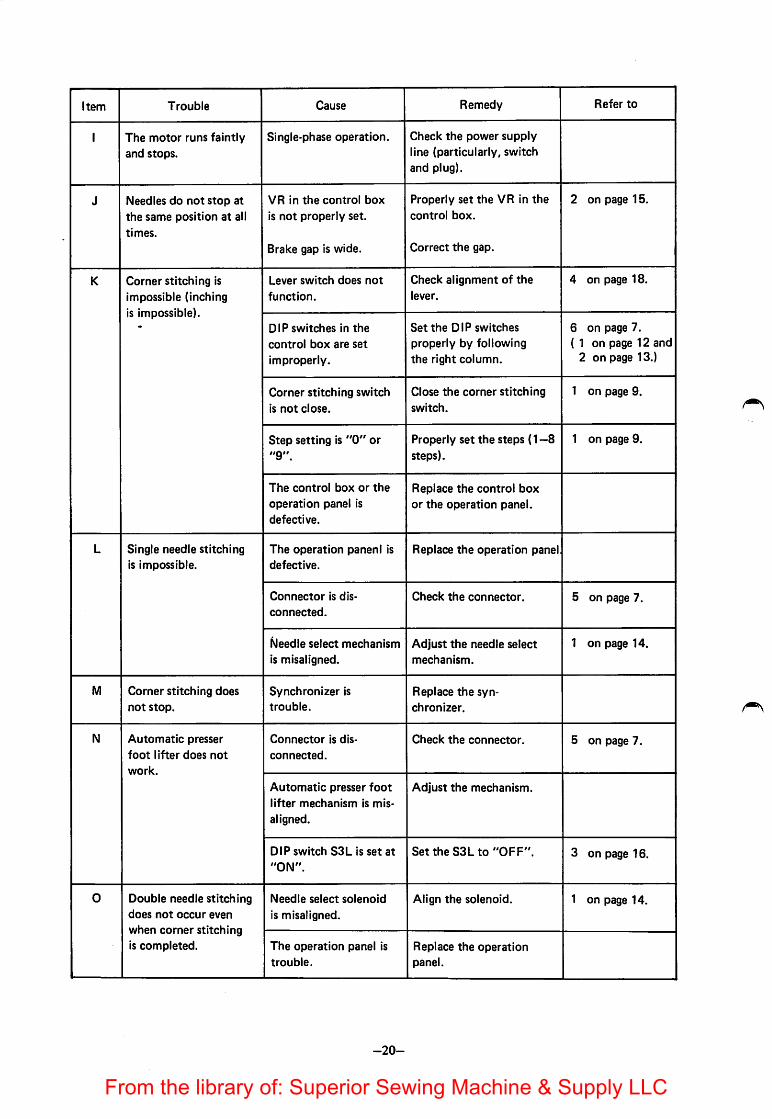
Item Trouble Cause Remedy Refer to
1 The motor runs faintlyand stops.
Single-phase operation. Check the power supplyline (particularly, switchand plug).
J Needles do not stop at
the same position at alltimes.
VR In the control box
Is not properly set.
Brake gap is wide.
Properly set the VR In thecontrol box.
Correct the gap.
2 on page 15.
K Corner stitching Is
Impossible (InchingIs Impossible).
Lever switch does not
function.
Check alignment of the
lever.
4 on page 18.
DIP switches In the
control box are set
Improperly.
Set the DIP switches
properly by following
the right column.
6 on page 7.( 1 on page 12 and
2 on page 13.)
Corner stitching switch
is not close.
Close the corner stitching
switch.
1 on page 9.
Step setting Is "0" or"9".
Properly set the steps (1 —8steps).
1 on page 9.
The control box or the
operation panel isdefective.
Replace the control boxor the operation panel.
L Single needle stitchingIs Impossible.
The operation paneni Is
defective.
Replace the operation panel
Connector Is dis
connected.
Check the connector. 5 on page 7.
Needle select mechanism
Is misaligned.Adjust the needle select
mechanism.
1 on page 14.
M Corner stitching doesnot stop.
Synchronizer Is
trouble.
Replace the synchronizer.
N Automatic presser
foot lifter does not
work.
Connector Is dis
connected.
Check the connector. 5 on page 7.
Automatic presser foot
lifter mechanism Is mis
aligned.
Adjust the mechanism.
DIP switch S3L is set at
"ON".
Set the S3Lto "OFF". 3 on page 16.
0 Double needle stitchingdoes not occur even
when corner stitchingIs completed.
Needle select solenoid
is misaligned.
Align the solenoid. 1 on page 14.
The operation panel Is
trouble.
Replace the operationpanel.
-20-
From the library of: Superior Sewing Machine & Supply LLC

Item Trouble Cause Remedy Refer to
P Single needle operationoccurs through cornerstitching is completed.
Needle select solenoid
does not return to the
original position.
Align the needle select
solenoid.
1 on page 14.
Q The sewing machine
does not stop with theneedles at UP position,but goes on running.
Synchronizer is
trouble.
Replace the synchronizer. 8 on page 8.
R The presser foot does
not goes up after the
needles stop at UP po
sition.
Refer to the description
at item N.
Operation panel istrouble.
Replace the operation
panel.
S While number of
stitches and needle
select setting are
changed, corner stitch
ing does not
correspondingly change.
Operation panel is
trouble.
Replace the operation
panel.
T Pedal heeling down isheavy.
Pedal switch lever part is
not properly adjusted.
4 on page 18.
-21-
From the library of: Superior Sewing Machine & Supply LLC

A MITSUBISHI ELECTRIC CORPORATIONHCAO OmCE:MfTSUBISKI DENKI BLOG.MARUNOUqKI. TOKYO 100 laEX: J24S32 CABLE MaCO TOKYO
(8505) ROD Printed in JapanFrom the library of: Superior Sewing Machine & Supply LLC