mitsubishi industrial robot - allied automation, inc. · · 2016-09-062012-06-05 bfp-a8006-j...
TRANSCRIPT

Mitsubishi Industrial Robot
SAFETY MANUAL
BFP-A8006-M


NOTE TO THE USER
1. AS FOR THE ASSURANCE OF SAFETY IN DESIGN AND CONSTRUCTION OF ROBOT SYSTEM, READ THIS MANUAL FIRST.
2. PLEASE MAKE SURE THAT THIS MANUAL IS DELIVERED TO END USERS FOR THEIR IMPLEMENTATION OF SAFETY.
3. DON’T USE ROBOTS IN A POTENTIALLY EXPLOSIVE ATMOSPHERE.
• ANY PART OF THIS PRINT MUST NOT BE REPRODUCED IN ANY FORM WITHOUT PER-MISSION.
•THIS PRINT IS SUBJECT TO CHANGE WITHOUT NOTICE.
Copyright(C) 1999-2014 MITSUBISHI ELECTRIC CORPORATION

Notes about the Europe new battery command (2006/66-/EC)
Note: This symbol mark is for EU countries only.This symbol mark is according to the directive 2006/66/EC Article 20 Information for end-users and Annex II.
Your MITSUBISHI ELECTRIC product is designed and manufactured with high quality materials and com-ponents which can be recycled and/or reused.
This symbol means that batteries and accumulators, at their end-of-life, should be disposed of separately from your household waste.
If a chemical symbol is printed beneath the symbol shown above, this chemical symbol means that the bat-tery or accumulator contains a heavy metal at a certain concentration. This will be indicated as follows:Hg: mercury (0,0005%), Cd: cadmium (0,002%), Pb: lead (0,004%)
In the European Union there are separate collection systems for used batteries and accumulators.
Please, dispose of batteries and accumulators correctly at your local community waste collection/recycling centre.
Please, help us to conserve the environment we live in!

Transportation Precaution
The United Nations’ Recommendations on the Transport of Dangerous Goods must be observed for trans-border transportation of lithium batteries by air, sea, and land.The lithium batteries (A6BAT, ER6, Q6BAT) used in Mitsubishi industrial robots contain less than 1 g of lith-ium and are not classified as dangerous goods. However, if the quantity of lithium batteries exceeds 24 bat-teries for storage, etc., they will be classified as Class 9: Miscellaneous dangerous substances and articles. Shipping less than 24 batteries is recommended to avoid having to carry out transport safety measures as the customer’s consignor. Note that some transportation companies may request an indication that the bat-teries are not dangerous goods be included on the invoice. For shipping requirement details, please contact your transportation company.

Waste Management
When disposing of this product, it is necessary to give consideration to the effective use of resources, waste handling and cleaning, and the collection and disposal of fluorocarbon. Please dispose of this product according to the waste management law of the country where it is used.
1. Effective Use of Resources(1) Please recycle the old product as much as possible.(2) For recycling purposes, we recommend disassembling this product into iron scrap and electrical
parts, so that they can be sold to appropriate vendors.
2. Waste Handling and Cleaning(1) Please try to sell the old product for recycling in order to reduce the amount of waste material.(2) When disposing of this product, please do so according to the requirements of the appropriate indus-
trial waste laws. Disposing of batteries and used grease by the customer will cause environment contamination.
3. Collection and Disposal of Fluorocarbon(1) Handle the coolant inside the heat radiation fins used for heat dispersion in the power supply unit
(converter unit) and the driving units (inverter unit, amplifier unit) appropriately, according to the des-ignated fluorocarbon collection and disposal regulations.
The applicable products that use fluorocarbon are the following units built in the CR4, CR7, CR8 and CR9 controllers manufactured in or before 2002.
Note: The V1 model includes the V14 and V14L modes, and the V2 model includes the V24 model.
Unit model name Charged coolant model name
MDS-B-CV-37 to 185HCFC141b
MDS-B-V1-20 to 45
MDS-B-V1-70 to 90HCFC123
MDS-B-V2-2010 to 4535


Revision history
Date Specifications No. Details of revisions
1999-06 BFP-A8006-* ・First print
2000-11 BFP-A8006-* ・Error in writing correction.
2002-10 BFP-A8006-B ・Error in writing correction.
2004-01 BFP-A8006-C ・Error in writing correction.
2004-05 BFP-A8006-D ・Robot System Safety Precautions was added.
2008-09 BFP-A8006-E ・Notes about the Europe new battery command was added.
2009-09 BFP-A8006-F ・The EC Declaration of Conformity was changed. (Correspond to the EMC directive; 2006/42/EC)
2012-03-05 BFP-A8006-G ・F series was added.
2012-03-21 BFP-A8006-H ・Notes were added to the example of safety measures. (The measure against the noise, The electric specification of the output terminal)
2012-06-05 BFP-A8006-J ・The description of "Referring to the instruction manual for each type, when connecting the external emergency stop system" was added.
2012-10-25 BFP-A8006-K ・The statement about trademark registration was added.・The wiring example 5 of the "Examples of safety protection device configuration (CR750 and
CR751 series)" was corrected. (Error in writing)
2014-03-31 BFP-A8006-M ・The grounding representation was corrected.

*Introduction
Nowadays, industrial robots have been widely introduced to many production lines and are esti-mated to increase more and more in the future. This is owing to many merits of industrial robots that conventional machines don't possess. Industrial robots, in place of human, can do elaborate jobs without saying. They can also continue to work in hazardous conditions for human without taking a rest.On the contrary, industrial robots could act peculiar hazards against human if sufficient precautions were not provided. Industrial robots may give rise to hazards of injuring operators or damaging equipment.We who have given created them must do our best to make them work safely to prevent such acci-dents. However, after they are shipped, safeguarding measures must be taken by the system inte-grators and/or the end users as well. This manual is intended to give general precautions and safeguarding to secure safety of all persons who are involved in the robots. Before introduction, installation, arrangement and so on of the robots, please read through this manual as well as the operation manual of the robot itself to be able to operate them safety and efficiently.
The fundamental idea of this manual bases on the following 'EC directive', 'International standard', and 'European norm', provisions of which are cited frequently through this manual. Refer to these documents if necessary.
• Machine directive: 89/392/EEC, 91/368/EEC, 98/37/EC, 2006/42/EC• ISO 10218 (1992): Manipulating industrial robots - Safety• BS7228 Part6 (1992): Recommendations for safety
Applicable ModelsThis manual is targeted for the following model series.
• A/S Series• T Series• SD/SQ/F Series
・ No part of this manual may be reproduced by any means or in any form, without prior consentfrom Mitsubishi.
・ The contents of this manual are subject to change without notice.・ This specifications is original.・ The ETHERNET is a registered trademark of the Xerox Corp.・ All other company names and production names in this document are the trademarks or registered
trademarks of their respective owners.
Copyright(C) 1999-2014 MITSUBISHI ELECTRIC CORPORATION

Contents
i
Page
1 Fundamental concept of safety measures ...................................................................................... 1-1
1.1 Purpose, application .................................................................................................................. 1-1
1.2 Operating environments ............................................................................................................ 1-1(1) Power supply .................................................................................................................... 1-1(2) Electromagnetic noise ...................................................................................................... 1-1(3) Static electricity ................................................................................................................. 1-1(4) Temperature, humidity ...................................................................................................... 1-1(5) Atmosphere ...................................................................................................................... 1-2(6) Liquid ................................................................................................................................ 1-2(7) Vibration .......................................................................................................................... 1-2(8) Radioactive ray ................................................................................................................. 1-2(9) Air pressure ...................................................................................................................... 1-2
1.3 Safeguarding ............................................................................................................................. 1-31.3.1 Prevention of hazards in automatic operation ...................................................................... 1-31.3.2 Safeguarding in programming .............................................................................................. 1-41.3.3 Safeguarding in maintenance and trouble shooting ............................................................. 1-41.3.4 Verification of safety before starting operation ..................................................................... 1-4
2 Safety considerations in each operation ......................................................................................... 2-5
2.1 Unpacking .................................................................................................................................. 2-5
2.2 Carrying ..................................................................................................................................... 2-5
2.3 Preparation of installation and operation ................................................................................... 2-62.3.1 Robot arm, controller and control panel ............................................................................... 2-62.3.2 Cables .................................................................................................................................. 2-62.3.3 Hands ................................................................................................................................... 2-72.3.4 Teaching pendant ................................................................................................................ 2-72.3.5 Grounding ............................................................................................................................ 2-72.3.6 Emergency stop ................................................................................................................... 2-82.3.7 Safety stop ........................................................................................................................... 2-82.3.8 Indicators ............................................................................................................................. 2-82.3.9 Isolation of power sources ................................................................................................... 2-82.3.10 Applying power ................................................................................................................... 2-8
2.4 Teaching and programming ....................................................................................................... 2-9
2.5 Program verification ................................................................................................................... 2-9
2.6 Automatic operation ................................................................................................................. 2-10
2.7 Maintenance ............................................................................................................................ 2-10
2.8 Trouble shooting ...................................................................................................................... 2-11
2.9 Modifications ............................................................................................................................ 2-11
2.10 Disposal ................................................................................................................................. 2-11
3 Safeguarding ................................................................................................................................. 3-12
3.1 Safeguard ................................................................................................................................ 3-12
3.2 Awareness means ................................................................................................................... 3-12
4 System documentation .................................................................................................................. 4-13
5 Training ......................................................................................................................................... 4-13
6 Degree of danger and damage, and indications ........................................................................... 4-13
7Examples of safety protection device configuration ...................................................................................Appendix-14
Appendix 7-1: Safety protection device configuration methods ........................................ Appendix-14(1) Stop functions .................................................................................................... Appendix-14(2) Safety protection functions ................................................................................ Appendix-14(3) Safety protection measures ............................................................................... Appendix-15
Appendix 7-2: Examples of safety protection device configuration ................................... Appendix-16

1Fundamental concept of safety measures
Purpose, application 2-1
1 Fundamental concept of safety measures
This section explains the fundamental concept of safety that should be under stood by all persons who use robots.
1.1 Purpose, applicationWe have developed industrial robots to contribute to economic activities, human health and safety by improving productivity, flexibility, and quality of manufacturing industry, as well as by securing safety in haz-ardous operation.Therefore, we request users to understand our intention and never to make use of robots for purpose against above intention.Typical applications of robots in manufacturing industry have included, for example, parts assembling, test-ing, machining, loading and unloading palletizing, sealer dispensing, painting, soldering brazing and deburr-ing. In other applications such as education, and even amusements, robots are now being used.However, applications of robots will not be limited to those above. If you make a use of a robot in a new application, particular attention should be paid in order to assess the risks on your own responsibility, because a different application may involve different hazards and different levels of risks. (e.g. handling of explosive or flammable material, harmful laser light beam, radioactive ray, poisonous chemicals, and biolog-ically harmful microbe.)
1.2 Operating environmentsThe operating environments of a robot can affect its lifetime, function, performance, and safety. If the operat-ing environments of a robot do not satisfy the following conditions, appropriate means should be taken to prevent the robot from being exposed to such undesirable conditions.
(1) Power supply1) The line voltage must be within ±10% of the rating.2) The duration period of an instantaneous power failure must be within 15 milliseconds.3) The power supply must provide enough electricity needed at the maximum consumption.
[Recommendation] ....... a larger transformer; a stabilized power supply; an UPS.
(2) Electromagnetic noise 1) The surge voltage applied to a line must be less than 1000V, and its duration period must be within
1μs.2) The robot must be isolated from a large-sized inverter, a high-frequency oscillator, a large-sized con-
tactor, and a welding machine, where intense electromagnetic is generated.[Recommendation] ....... a noise-cut transformer; a noise filter; reinforcement of ground lines and elec-
tromagnetic shields; isolation by keeping away from noise sources; reduction of noise level of emission.
(3) Static electricity1) Where static electricity exceeding 4kV could be directly applied on the robot body or controller. Or
where static electricity exceeding 8kV could be applied through airborne electrical discharge.[Recommendation] ....... prevention from storing static electricity; discharging of static electricity
(4) Temperature, humidity1) The ambient temperature must be with in the rated range. (between 0°C and 45°C for M series,
between 0°C and 40°C for E series)2) The robot must be kept away from direct sunlight and any heat source.3) The relative humidity must be within the rated range. (between 45% and 85%, non-condensing)
[Recommendation] ....... a local heating or cooling equipment; a heat-resistant jacket; isolation by keeping away from a heat source; NOTE: Countermeasure is needed against static electricity in low humidity and dewdrop in high humidity.

2-2 Operating environments
1Fundamental concept of safety measures
(5) Atmosphere1) No dust, no oil mist, and no corrosive gas must be contained in the atmosphere.2) No metal shavings and conductive material must scattered.3) No combustible and explosive gas must be contained in the atmosphere.
[Recommendation]........The oil mist proof types are recommended. Use the dust or an oil mist resis-tant jacket. NOTE: Never use robots in a combustible or explosive atmosphere. Install the controller in a shielded enclosure if used in a bad atmosphere, as the controller itself has openings for cooling.
(6) Liquid1) Water and other liquid must not splash a robot and a controller directly.2) Any portion of a robot and a controller must not be dipped in water and other liquid.
(7) Vibration1) The vibration and shock must be 3.5G at maximum during transportation.2) The vibration and shock must be 0.5G at maximum during normal use.
[Recommendation]........Enforcement of rigid packing and shock absorbing
(8) Radioactive ray1) The radioactive ray must not be more than a permitted level of ordinary person.
[Recommendation]........ isolation from and of a radioactive source
(9) Air pressure1) The height above sea level should not be more than 1000m. The robot can not work in vacuum.
[Recommendation]........giving pressure to reach to 1 atmosphere

1Fundamental concept of safety measures
Safeguarding 2-3
1.3 Safeguarding 1.3.1 Prevention of hazards in automatic operation
If the operation of an industrial robot can give rise to hazards of impact, trapping, or flying objects released by the gripper, methods for protection of person(s) must be taken using fixed guards or fences.(see Fig. 1-1) It is obvious that if an operator does not enter into a safeguarded space, no hazard of impact nor trapping will occur. Therefore, the separation of any person from any robot by creating a safeguarded space and a restricted space is one of the fundamental principles of safeguarding. In other words, the principle prohibits a person from entering the safeguarded space during automatic oper-ation. Further, the interlock must be installed so that the guard remains locked closed or opening the guard gives a stop instruction during automatic operation.In addition to a guard and a fence, a presence sensing device that detects any intrusion into a space, or awareness means that provides a signal to persons of an approaching or present hazard may be used.
Fig.1-1:Example of restricted space and safeguarded space
Definitions in above figureLimit region : Max. region limited with mechanical stoppers, etc.Max. region : Max. movement region of robot, including hand installed on end, etc.Safety protection region : Region protected with safety fence, including limit region
DoorSafeguard
Robot
Restricted space
Maximum space
Safeguarded space

2-4 Safeguarding
1Fundamental concept of safety measures
1.3.2 Safeguarding in programmingSome maintenance and programming personal are at times required to be within the restricted space while power is available to the machine actuators for teaching, program verification, maintenance, and trouble shooting.
On the other hand, it is recognized that operational characteristics of robots can be significantly different from those of other machines and equipment. Robots are capable of high energy movements through a large volume beyond the base of robots. The pattern and initiation of movement of the robot arm are difficult to predict and can vary because of variables in product and environmental conditions.
Therefore, the elimination of hazards or at least their reduction must be carried out during interventions in the safeguarded space while power is available to the machine actuators. Accordingly, a design of the robot system such as to allow the maximum number of tasks to be performed from outside the safeguarded space must be involved. However, if some task requires personnel to be within the safeguarded space, provision of compensatory means of safety must be taken instead of suspending safeguards.
If several robots are installed in a safeguarded space to constitute a certain system, each robot and device must be designed and installed so that each can be controlled independently.
An example of an interference mistake by the robot and peripheral device such as the workpiece, which may occur easily during teaching, is shown for reference in Fig. 1-2. Here, (A) is interference during move-ment with joint interpolation, (B) is interference caused by an incorrectly set movement destination position No., and (C) is interference caused by an incorrect hand grip open/close setting.
Fig.1-2:Example of work mistake during teaching
1.3.3 Safeguarding in maintenance and trouble shootingWhen entering the safeguarded space for inspection, repair, cleaning, and maintenance, be sure to stop the robot and shut down the power supply with placing a lock and/or tag on the energy isolating device to pre-vent unwilling operation. When an intervention within the safeguarded space while power is available to the robot is required, appropriate safe working procedures must be used to prevent a sudden motion of a robot and a careless operation of person.
1.3.4 Verification of safety before starting operationPrior to the use in normal operation, ensure the proper operation of the robot and the robot system. If any damage or malfunction that may lead to an accident is found, required corrections must be completed and retesting must be performed.Be sure that all system emergency stop devices remain functional.
P1
P2
P2
P1 P3
P4
(A)
(B)
(C)
Linear interpolation
Joint interpolation
Grip
Hand
Workpiece
Peripheral device
Peripheral device

2Safety considerations in each operation
Unpacking 2-5
2 Safety considerations in each operation
This section refers to the general precautions in each operation from unpacking to trouble shooting of robot system. Prior to the actual use of a robot, be sure to read relating items in the attached operation manual together with this safety manual.
2.1 Unpacking (1) The robot and the controller are packed separately in a corrugated cardboard for shipment. Be sure
to obey the unpacking procedure indicated outside the corrugated cardboard.(2) When taking the robot out of shock absorbers, never hold resin covers. If you hold these covers, they
may be damaged.(3) Keep the used corrugated cardboards and the used shock absorbers for the secondary transporta-
tion in future.
2.2 Carrying(1) Confirm the weight on the rated nameplate before transporting the robot arm.(2) If the robot arm weighs 30kg or less, two workers must carry the robot while holding the unit at the
bottom. If transportation handles are provided, use these handles when transporting. Always leave the robot arm fixing plate installed during the transportation work.
(3) When transporting the robot arm, prepare even-length wires that can sufficiently withstand the robot weight. Pass these wires through the designated eye bolts, and suspend the robot with a crane. Always leave the robot arm fixing plate installed during the transportation work.
(4) When putting the robot or the controller on an installing base or a pushcart, don't apply an excessive shock and an excessive vibration to the robot and the controller.
(5) When transporting the robot after installed, be sure to release brakes of the robot arm and from the pose the same as the shipping pose. Don't carry or transport the robot with its arm extended.
(6) When putting the robot on an installing base temporarily, fix the robot with one or more bolts to pre-vent from falling down.
(7) When transporting the open cooling structure controller, as a general rule, two workers must insert their hands into the clearance at the bottom from the front side and back side. Make sure that exces-sive force is not applied on the switches, terminal block, connectors, or heat radiating fin, etc.
(8) Many resin covers are used on the exterior surface of the robot. Never hold these parts and never apply forces to them. If you carry the robot by holding these covers, that may cause hazards of dam-aging covers and eventually dropping the robot.
(9) Before transporting the robot, the arm fixing plate must be installed.

2-6 Preparation of installation and operation
2Safety considerations in each operation
2.3 Preparation of installation and operation2.3.1 Robot arm, controller and control panel
(1) When installing the robot arm, secure the area required for the work based on the layout design before-hand. At the same time, provide a sufficient clearance so that the robot's movable sections and periphery do not catch or collide. If the robot requires the origin to be set, make sure that there is no interference with the periphery in the origin setting posture.
(2) If the limitation of range of motion is required by the plan, please consult with us in advance. Only the range of J1 axis can be limited at some fixed points. Alternative method of limiting the range of motion may be provided only if they are designed, constructed, and installed to achieve the same level of safety as the mechanical stops. This may include using the limit switches according to IEC 204-1.
(3) Install the controller and control panel starting device where the entry of operators in the safety pro-tection region (inside the safety fence) can be confirmed from the operator control position.
(4) If the working areas of robots overlap each other, provide interlock functions to prevent the robots from simultaneously entering their common area. (position detecting switches, etc.)
(5) When the safeguarding methods are not in place prior to commissioning and functional testing, interim means of designating the restricted space must be in place before proceeding.
(6) When it is intended that operators will perform manual operations associated with the robot, such as loading and unloading of parts, this must be taken into account in the arrangement of the robot sys-tem, either by providing loading devices so that the operator cannot access the hazardous area, or by providing appropriate safeguards for the manual activity.
(7) Securely fasten the robot to the robot to the specified installing surface with four fastening bolts being careful to prevent deviation of the position. The installing base requires enough stiffness to withstand the weight of the robot and the reaction force.
(8) Remove the arm fixing plate before operating the robot.(9) When using ceiling suspension or wall hanging installation methods, a jig allowing use of a standard
lift, etc., is available from Mitsubishi. Please consult with your dealer for more information.(10) Install the controller outside the safety protection region (outside the safety fence). Install the con-
troller's operation panel so that the operator can monitor the robot without facing his/her back to the robot, and at a height where the panel can be operated easily. (For maintenance workability, set the operation panel height at 0.6m or more.)
(11) Install the controller on a level surface. Be sure not to prevent the heat fin from radiating heat and the fan from ventilating hot air. The ambient temperature of the controller must be within the rated range.
(12) If the controller must be fixed to prevent dropping or movement, etc. from external vibration, always fix on the base surface. (Do not remove the rubber legs.)
(13) When installing the robot, the controller and the peripheral equipment, take mens of access into account to allow access in safety to all areas used for production, adjustment and maintenance oper-ations.
(14) Do not get on or hang from the robot.(15) Do not get on or place heavy objects on the controller.(16) Make sure that foreign matter does not enter the robot arm or controller. Entry of conductive matter
such as screws or metal pieces, or the entry of flammable matter such as oil could lead to ruptures or damage, etc.
2.3.2 Cables(1) Tighten the connectors of the cables between the robot and the controller according to the instruc-
tions of the manual.(2) Don't pull or bend the cables with force. Protect the cables with ducts or covers if necessary.(3) When installing ducts or covers, means should be taken to prevent persons from stumbling, and cau-
tion signs should be indicated necessary.(4) Keep the robot machine cables and the external I/O cable away from other cables such as power
cables and earth lines. Be sure that the external I/O cable is shielded.(5) Do not mistake the terminal connections. Failure to observe this could lead to ruptures or damage,
etc.(6) Do not mistake the polarity (+, -). Failure to observe this could lead to ruptures or damage, etc.(7) When moving the robot on a slide rail, never use standard machine cables of the robot due to the
poor resistance against bending. In this case, be sure to use flexible machine cables of the robot pre-pared as options.

2Safety considerations in each operation
Preparation of installation and operation 2-7
(8) Before connecting the power source line, be sure that the voltage of the power is within the rated range and the power switch of the controller is off. Then connected to the correct portion.
(9) Do not connect or disconnect the cables or connectors while the power is ON.
2.3.3 Hands(1) When using the optional motor-operated hand or the pneumatic hand, follow the instructions of the
manual. Be sure that the total weight including workpieces is within the rated load.(2) If necessary, attach the specially machined picking tool to the end of the hand according to the shape
of workpieces. Be sure that the tool has no sharp edges nor projections except functionally neces-sary portions.
(3) When fixing a customer-made hand, be sure that the total weight including workpieces is within the rated load. Especially, when fixing an unbalanced hand, the rated torque of the wrist axes should also be taken into account.
(4) When attaching a customer-made hand to the flange of the robot, size it securely with specified bolts. Be sure that the hand has no sharp edges nor projections except functionally necessary portions, and provide covers and other protections as necessary.
(5) If cables and hoses are connected to the hand, prevent cables and hoses from getting twisted round or damaged and from restricting the motion of the robot.
(6) When using a pneumatic hand, supply clean air which pressure is within 0.7MPa[7kgf/cm2] as the pressure higher than this may lead to a breakage of the internal pneumatic pipe in the robot arm.
(7) If there is the possibility of a hand releasing a workpiece during motion thus causing a hazardous conditions, necessary means should be taken for the gripping mechanism of the hand to prevent such hazards.
(8) The hand must be designed and constructed so that power failure does not cause release of the load or result in a hazardous condition. To keep the opening or closing state of a pneumatic hand even when the electric power fails, make use of a double solenoid to control the hand.
(9) Grasping a workpiece charged with static electricity could cause malfunctioning due to electrical-dis-charge through the hand and robot arm. Thus, always use an insulated structure for the hand and robot arm. When a charged workpiece is placed, the device on which is it placed could malfunction due to the electrical-discharge. Always structure the system so that the charged workpiece's charge is discharged with an appropriate electrical-discharge route.
(10) Power for the confirmation sensor is supplied to the hand check cable enclosed with the robot (or optional). If the cable end cannot be treated sufficiently due to this, the end could contact the periph-eral device or robot arm while the power is turned ON, and could lead to short circuit accidents. Thus, always treat the end when using the hand check cable.
2.3.4 Teaching pendant(1) Tighten the connector of the teaching pendant cable. Don't pull or bend the cable with force.(2) Determine the area where the teaching pendant is stored, and prevent the pendant from being care-
lessly dropped thus causing malfunction or damage.
2.3.5 Grounding(1) Be sure to ground the robot and the controller electrically according to the instructions of the manual.
The grounding is indispensable to prevent electric shock, to reduce electrostatic charges, to improve electric noise resistance, and to reduce electromagnetic interference.
(2) Use a wire of more than 2 mm2 in cross section, and make its length as short as possible.(3) The robot and the controller should be grounded separately. Keep the ground points away from those
of other large electric equipment.

2-8 Preparation of installation and operation
2Safety considerations in each operation
2.3.6 Emergency stop(1) Install the manual emergency stop switch near the robot where it can be operated easily. Connect it
to the external emergency stop terminal on the controller. (Always close B type contact, provided with a mechanical lock function. Complaint with IEC204-1 specifications.) When there are multiple instal-lation places, install multiple switches. Refer to the instruction manual for the electrical specifications.
(2) Install a switch on the safety protection devices, such as the safety fence door. Provide an interlock mechanism so that the robot will enter the emergency stop state if the switch is activated. (Example: The emergency stop state is entered when the safety fence door is opened during robot operation.)
(3) In the case of the complex robot system designed to work together, emergency stop devices should stop not only the robot itself but also all relating equipment if its continued operation can be danger-ous. In this case, for example, an emergency switch that has more than one contacts is desirable.
2.3.7 Safety stop(1) Install the stop switch near the robot where it can be operated easily. Connect it to the external input/
output terminal on the controller. When there are multiple installation places, install multiple switches. Refer to the instruction manual for the electrical specifications.
(2) Do not install the stop switch on the safety protection devices, such as the safety fence door. Install an emergency stop switch on the safety protection device.
(3) Do not enter the safety protection region (inside the safety fence) in the stopped state.
2.3.8 Indicators(1) Pertinent information should be provided such as clearly indicating robot working modes and display-
ing the reason for unprogrammed robot stop. For this purpose, use the dedicated I/O bits of the con-troller. (e.g. run, wait, reset, error)
(2) Where the risk may arise by a fault in the operation of unsupervised machinery, the machine must be equipped to give an appropriate acoustic or light signal as a warning.
2.3.9 Isolation of power sources(1) Each robot system must have means to isolate each of its power sources by manual operation.(2) Isolation must be either visible (visible interruption of continuity in the power supply) or visibly
ensured by permitting a check of the position of the operating control on the isolating unit, and it must be made clear which areas of the machine are isolated.
(3) If necessary, means should be taken to lock the isolation device in the 'OFF' or 'OPEN' position to prevent careless operation.
(4) When the power is shut down, the hand drops down more or less by itself because no brakes are installed in the wrist axes. If this may lead to a hazardous condition, the attitude of the wrist should turn down beforehand or the power should be shut down timely to prevent from hazardous condition.
(5) When the power to the robot is shut off, the hand, etc., may drop slightly from the time that the power is shut off to when the brakes activate. If there is any risk of interference, etc., with the peripheral devices, set the robot to a posture where a hazardous state will not be created before shutting off the power.
2.3.10 Applying power(1) Before turning on the power supply, check that there is no person within the safeguarded space and
that tools and other pieces are not left there.(2) Verify that the cables, hoses, and connectors are not damaged nor disconnected nor loose.(3) Verify that the workpiece and the peripheral equipment are positioned as specified. Also verify that
applying power to peripheral equipment does not result in hazardous motion.(4) If some sequence in applying power to peripheral equipment may cause a hazardous condition, obey
the safety sequence specified in advance. (The situation is the same as in the power shut down.)(5) After applying power, be sure to verify that emergency stop devices and other safeguards are func-
tional.(6) Verify that each axis of the robot moves functionally by job operation and is restricted in motion as
intended.(7) Do not open the cover or door of controller, after turning on the power supply.
2Safety considerations in each operation
Teaching and programming 2-9
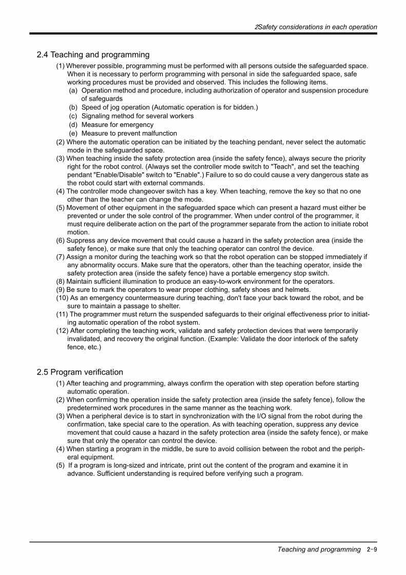
2.4 Teaching and programming(1) Wherever possible, programming must be performed with all persons outside the safeguarded space.
When it is necessary to perform programming with personal in side the safeguarded space, safe working procedures must be provided and observed. This includes the following items.(a) Operation method and procedure, including authorization of operator and suspension procedure
of safeguards(b) Speed of jog operation (Automatic operation is for bidden.)(c) Signaling method for several workers(d) Measure for emergency(e) Measure to prevent malfunction
(2) Where the automatic operation can be initiated by the teaching pendant, never select the automatic mode in the safeguarded space.
(3) When teaching inside the safety protection area (inside the safety fence), always secure the priority right for the robot control. (Always set the controller mode switch to "Teach", and set the teaching pendant "Enable/Disable" switch to "Enable".) Failure to so do could cause a very dangerous state as the robot could start with external commands.
(4) The controller mode changeover switch has a key. When teaching, remove the key so that no one other than the teacher can change the mode.
(5) Movement of other equipment in the safeguarded space which can present a hazard must either be prevented or under the sole control of the programmer. When under control of the programmer, it must require deliberate action on the part of the programmer separate from the action to initiate robot motion.
(6) Suppress any device movement that could cause a hazard in the safety protection area (inside the safety fence), or make sure that only the teaching operator can control the device.
(7) Assign a monitor during the teaching work so that the robot operation can be stopped immediately if any abnormality occurs. Make sure that the operators, other than the teaching operator, inside the safety protection area (inside the safety fence) have a portable emergency stop switch.
(8) Maintain sufficient illumination to produce an easy-to-work environment for the operators.(9) Be sure to mark the operators to wear proper clothing, safety shoes and helmets.(10) As an emergency countermeasure during teaching, don't face your back toward the robot, and be
sure to maintain a passage to shelter.(11) The programmer must return the suspended safeguards to their original effectiveness prior to initiat-
ing automatic operation of the robot system.(12) After completing the teaching work, validate and safety protection devices that were temporarily
invalidated, and recovery the original function. (Example: Validate the door interlock of the safety fence, etc.)
2.5 Program verification(1) After teaching and programming, always confirm the operation with step operation before starting
automatic operation.(2) When confirming the operation inside the safety protection area (inside the safety fence), follow the
predetermined work procedures in the same manner as the teaching work.(3) When a peripheral device is to start in synchronization with the I/O signal from the robot during the
confirmation, take special care to the operation. As with teaching operation, suppress any device movement that could cause a hazard in the safety protection area (inside the safety fence), or make sure that only the operator can control the device.
(4) When starting a program in the middle, be sure to avoid collision between the robot and the periph-eral equipment.
(5) If a program is long-sized and intricate, print out the content of the program and examine it in advance. Sufficient understanding is required before verifying such a program.

2-10 Automatic operation
2Safety considerations in each operation
2.6 Automatic operation(1) Before initiating the automatic operation, ensure that there are no exposed persons in the safe-
guarded space. If it is impossible, the control system must be designed and constructed so that an acoustic and/or visual warning signal is given whenever the machinery is about to start. The exposed person must have the time and the means to take rapid action to prevent the machinery from starting up. (e.g. installation of the emergency switches inside the safeguarded space)
(2) Before initiating the automatic operation, be sure that all peripheral equipment is functional and there is no signals indicating malfunction.
(3) Always start automatic operation outside the safety protection area (outside the safety fence). Even when resuming operation by resetting after stopping the robot with emergency stop, etc., during automatic operation, always start outside the safety protection area (outside the safety fence).
(4) Before starting automatic operation, always confirm that the work details and selected program match. Use low-speed operation, when possible, until the first cycle ends.(Use the speed override change function.)
(5) If any abnormality is observed in the robot or peripheral devices, stop the operation immediately. Note that if a new risk is posed due to the position where the robot is stopped, etc., take care to the timing for stopping the robot.
(6) If the robot stops due to an unknown cause during automatic operation, avoid approaching the stopped robot. When the robot must be approached, input the emergency stop, or turn the main power off first. When turning the main power off, make sure that there will be no new risk caused.
(7) When halting and resuming the program during automatic operation, make sure that there will be no new risk with the peripheral device when the program is started. (Adequacy of work start position, necessity of peripheral device initialization, etc.)
(8) When the modification of the program is done during the suspension, be sure to verify the program at least one time before initiating the automatic operation.
(9) When selecting a different operation speed with the speed override change function during automatic operation, make sure that there will be no new risk caused. (Risk from speed that is too fast, or too slow)
(10) If a held workpiece or other object may fly out and cause a hazard by the centrifugal force during automatic operation or by the impact force of an emergency stop, suitable means must be taken to prevent such hazard.
(11) When an emergency stop device is activated or the power is shut down, the hand drops down more or less by itself because no brakes are installed in the wrist axes. Also, when speed of the robot is fast, even the axis with a brake may not stop immediately because of its remaining power of speed. Prevent the hand from conflicting with peripheral equipment.
(12) If the robot collides with a workpiece or the peripheral equipment at high speed due to e.g. a pro-gram error, then the workpiece, the peripheral equipment, the robot arm, and the reduction system of the robot may be considerably damaged. To avoid the hazardous condition caused by the collision, particular attention should be paid to assess the risks.
2.7 Maintenance(1) Where possible, maintenance of the robot and peripheral equipment should be performed from out-
side the safeguarded space.(2) When operations from outside the safety protection area (outside the safety fence) are not possible
and the fence must be entered, as a general rule, turn the power off first. At this time, make sure that no new risk will be caused by turning the power off.
(3) When work must be carried out inside the safety protection area (inside the safety fence) without turning the power off, always secure the priority right for the robot control. (Always set the controller mode switch to "Teach", and set the teaching pendant "Enable/Disable" switch to "Enable".) Failure to so do could cause a very dangerous state as the robot could start with external commands.
(4) If the stored energy may cause a hazardous condition after shutting down the power, means must be provided for the controlled release of stored energy. This energy source may be in the from of (but not limited to) fluid pressure accumulators, capacitors, springs, counter balances, and flywheels. Appropriate label must be affixed to each stored energy source.
(5) Do not open the controller door or cover immediately after turning the power off. Wait for the time given in the controller and instruction manual before opening the door or cover.

2Safety considerations in each operation
Trouble shooting 2-11
(6) Be sure to place working notices on the power supply and start switches to prevent a third person from operating them carelessly. If necessary, provide a watchman to operate the emergency stop device immediately when the robot operators unexpectedly.
(7) Securely carry out daily and periodic inspections referring to the operation manual. Regarding to the maintenance of the robot system, observe the inspection and maintenance program of the robot sys-tem manufacturer. If a skilled operation is needed for the robot itself, consult with our service shop.
(8) When maintaining the controller, check the normal operation of the internal cooling fan by e.g. exam-ining the air flow.
(9) When the brakes are released, the robot will drop with its own weight, so make sure that there are no operators in the robot's movable range. If there is any risk of interference, etc., with the peripheral devices, set the robot to a posture where a hazardous state will not be created before releasing the brakes.
(10) A small amount of lubricating grease may ooze out of the robot arm. If the surrounding environment could be contaminated from this grease dropping, check for grease oozing during the periodic inspection. If any grease is oozing out, wipe it off before it contaminates the surrounding environ-ment.
(11) For maintenance, provide a sufficient space of working and sufficient illumination to produce an easy-to-work environment for operators.
(12) Don't modify the robot or use any unspecified parts. Be sure to prevent modifying any safety devices.
(13) When turning on the power after completing the maintenance, ensure that the restoration of the power does not result in hazardous condition.
(14) After completing the maintenance, the suspended safeguards must be returned to their original function. (e.g. interlocking guards must be functional.)
(15) Do not carry out a megger test (insulation resistance test) during the inspections.(16) Do not short-circuit, charge, heat, incinerate or disassemble the battery.
2.8 Trouble shooting(1) As with maintenance, consider whether the priority of the work can be set as (1) work outside the
safety protection region (outside the safety fence), (2) work inside the safety protection region (inside the safety fence) with the power turned off,(3) work inside the safety protection region (inside the safety fence) with automatic operation canceled. If work must be carried out inside the safety protec-tion region (inside the safety fence) always set the controller mode switch to "Teach" and set the teaching pendant "Enable/ Disable" switch to "Enable".
(2) Be sure to place working notices on the power supply and start switches to prevent a third person from operating them carelessly. If necessary, provide a watchman to operate the emergency stop device immediately when the robot operates unexpectedly.
(3) If an alarm occurs on the robot, first check the alarm number or error mode which is useful is useful for trouble shooting. Record this information and refer to the corresponding pages of the manual.
(4) If the content of trouble shooting exceeds the range of the user, consult with our service shop as far as the robot is concerned with the trouble.
2.9 Modifications(1) Avoid modifications by user-judgements, and you must use the specified maintenance parts. Never
modify the sections related to safety, such as the emergency stop.(2) Faults caused by modifications made by the user will not be covered by the warranty.
2.10 Disposal(1) Treat this unit as general industrial waste.(2) Do not disassemble the parts.(3) Dispose of batteries according to local laws.(4) Contact the Mitsubishi Service Dept. for collection of used grease. Disposal of used grease by the
user will pollute the environment.
2-12 Safeguard
3Safeguarding
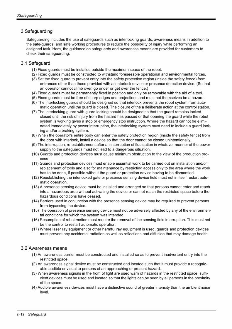
3 Safeguarding
Safeguarding includes the use of safeguards such as interlocking guards, awareness means in addition to the safe-guards, and safe working procedures to reduce the possibility of injury while performing an assigned task. Here, the guidance on safeguards and awareness means are provided for customers to check their safeguarding.
3.1 Safeguard(1) Fixed guards must be installed outside the maximum space of the robot.(2) Fixed guards must be constructed to withstand foreseeable operational and environmental forces.(3) Set the fixed guard to prevent entry into the safety protection region (inside the safety fence) from
entrances other than those provided with an interlock device or presence detection device. (So that an operator cannot climb over, go under or get over the fence.)
(4) Fixed guards must be permanently fixed in position and only be removable with the aid of a tool.(5) Fixed guards must be free of sharp edges and projections and must not themselves be a hazard.(6) The interlocking guards should be designed so that interlock prevents the robot system from auto-
matic operation until the guard is closed. The closure of the a deliberate action at the control station. (7) The interlocking guard with guard locking should be designed so that the guard remains locked
closed until the risk of injury from the hazard has passed or that opening the guard while the robot system is working gives a stop or emergency stop instruction. Where the hazard cannot be elimi-nated immediately by power interruption, the interlocking system must need to include a guard lock-ing and/or a braking system.
(8) When the operator's entire body can enter the safety protection region (inside the safety fence) from the door with interlock, install a device so that the door cannot be closed unintentionally.
(9) The interruption, re-establishment after an interruption of fluctuation in whatever manner of the power supply to the safeguards must not lead to a dangerous situation.
(10) Guards and protection devices must cause minimum obstruction to the view of the production pro-cess.
(11) Guards and protection devices must enable essential work to be carried out on installation and/or replacement of tools and also for maintenance by restricting access only to the area where the work has to be done, if possible without the guard or protection device having to be dismantled.
(12) Reestablishing the interlocked gate or presence sensing device field must not in itself restart auto-matic operation.
(13) A presence sensing device must be installed and arranged so that persons cannot enter and reach into a hazardous area without activating the device or cannot reach the restricted space before the hazardous conditions have ceased.
(14) Barriers used in conjunction with the presence sensing device may be required to prevent persons from bypassing the device.
(15) The operation of presence sensing device must not be adversely affected by any of the environmen-tal conditions for which the system was intended.
(16) Resumption of robot motion must require the removal of the sensing field interruption. This must not be the control to restart automatic operation.
(17) Where laser ray equipment or other harmful ray equipment is used, guards and protection devices must prevent any accidental radiation as well as reflections and diffusion that may damage health.
3.2 Awareness means(1) An awareness barrier must be constructed and installed so as to prevent inadvertent entry into the
restricted space.(2) An awareness signal device must be constructed and located such that it must provide a recogniz-
able audible or visual to persons of an approaching or present hazard.(3) When awareness signals in the from of light are used warn of hazards in the restricted space, suffi-
cient devices must be used and located so that the lights can be seen by all persons in the proximity of the space.
(4) Audible awareness devices must have a distinctive sound of greater intensity than the ambient noise level.

4System documentation
2-13
4 System documentation
The robot system documentation to be supplied by the robot system manufacturer shall contain the docu-ments of all the components included in the system with their identification *e.g. robot, associated equip-ment, safeguards. (It shall also as a minimum include the following:
(1) a clear, comprehensive description of the robot system and its installation including mounting and connection to external power sources;
(2) a description of foreseeable hazardous conditions and how to avoid them;(3) a description *including interconnecting diagrams (of the safeguards, interacting function, and inter-
locking of guards with hazardous conditions particularly with interacting installation;(4) any further instructions for use specific to the system.
5 Training Personal who perform maintenance or repairs on robot or robot systems must be trained in the procedures necessary to perform safely the required tasks. Therefore, the user must have an inspection and mainte-nance program and ensure those personnel are adequately trained and demonstrate competence to per-form their include, but is not limited to, the following:
(1) a review of applicable standard safety procedures and the safety recommendations of the robot man-ufacturer(s) and the robot system designers;
(2) a clear definition of assigned tasks and responsibility of each person;(3) identification and explanation of all control devices and their functions used in performing the
assigned task;(4) identification of the hazards associated with the assigned task;(5) the designated method(s) of safeguarding including the safe working procedures from the identified
hazards;(6) the method for testing or otherwise ensuring the proper functioning of the safeguards and interlocks.
6 Degree of danger and damage, and indications
Warning labels, corresponding to the degree of danger and damage (refer to Table 6-1) are attached to the robot arm and controller. Fully understand the meaning of the warning label, and take special care when handling. Do not remove, modify or contaminate the warning labels.
Table 6-1:Degree of danger and damage, and indications
Level Degree of danger and damage Caution prompting symbol and signal term
DANGERWhen there is a great risk that the operator could be
subject to fatalities or serious injuries Note1) if handling is mistaken.
Note1) Serious injury refers to injuries with after effects such as blindness, injury, burns (high temperature, low temperature), electric shocks, bone fracture, and poisoning, and to injuries requiring hospitalization or long-term medical treatment.
WARNINGWhen the operator could be subject to fatalities or seri-
ous injuries Note1) if handling is mistaken.
CAUTIONWhen the operator could be subject to injuries Note2) or
when only physical damage Note3) could occur if han-dling is mistaken.
Note2) Injury refers to injuries, burns and electric shocks that do not require hospitalization or long-term treatment.
Note3) Physical damage refers to extended damage to buildings, peripheral devices or workpieces.
DANGER
WARNING
CAUTION

Appendix-14 Safety protection device configuration methods
7Examples of safety protection device configuration
7 Examples of safety protection device configuration
Appendix 7-1: Safety protection device configuration methods(1) Stop functions
The following three methods are available for the stopping methods, a basic means of safety protection.
The other stop functions (emergency stop, temporary stop, etc.) are used to judge the input signal by the software and stop the operation. These are used to confirm the operation status, etc., but since the power is not shut off, these do not act as stop functions for safety protection.
(2) Safety protection functions
The following functions can be used for the safety protection devices.The following functions are also available as safety protection assembled in the product. These functions are already assembled in the teaching box, and will function as safety protection functions without special consideration.
(1) Hold to run .................This function starts operation only when the key, etc., is pressed. Operation stops when released.
(2) Double key pressing ..This function validates the commands only when two keys are pressed simul-taneously.
Emergency stop
The robot's drive power is directly shut off and the robot immediately stopped by the relay wire circuit "opening" operation (B contact) without passing through software or IC (Integrated Circuit.) An excessive force may be applied on the robot during high-speed operation.
Deadman stop
If the Enable/Disable switch on the teaching box is set to Enable, when the switch is released, the robot's drive power is directly shut off and the robot immediately stopped by the relay wire circuit "opening" operation (B contact) without passing through software or IC (Integrated Circuit.) An excessive force may be applied on the robot during high-speed operation.
Servo OFF
The input signal is judged by the software, the motor power is shut off, and the motor stopped. During operation, the motor will decelerate to a stop before the servo is turned OFF, so it may take some time before the stopping is com-pleted.
Safety speed limiter This sets the high-speed operation speed with the operation panel, etc. This function limits the speed to a safe speed.
Exclusive starting control
This prohibits the start command from a source other than the device being used.

7Examples of safety protection device configuration
Safety protection device configuration methods Appendix-15
(3) Safety protection measuresMeasures for safety protection using the above stop functions and safety protection functions are indicated below, together with the correspondence to Occupational Safety and Health Laws.
Measure A: Servo OFFMeasure B: State in which emergency stop can be applied immediately (teaching pendant emergency stop,
emergency stop switch inside fence, etc.)Measure C: Safety speed limiter, exclusive starting control (teaching pendant enable, manual mode, etc.)
Movable range
Operation status Drive source shut off MeasuresCorresponding
Provisions
OutsideDuring automatic operation
Not shut offSignaling of operation startProvision of fences and enclo-sures
Article 104Article 150, Clause 4.
Inside
During teaching, etc
Shut offMeasure A
Indication that work is in prog-ress
Article 150, Clause 3.
Not shut offMeasures to stop operation immediately, etc.Measure B and Measure C
Article 150, Clause 3, etc.
During inspec-tions, etc.
Shut offMeasure A
Indication that work is in prog-ress with operation stopped, etc.Indication that work is in prog-ress
Article 150, Clause 5.
Not shut offMeasures to stop operation immediately, etc.Measure B and Measure C?
Article 150, Clause 5, etc.

Appendix-16 Examples of safety protection device configuration
7Examples of safety protection device configuration
Appendix 7-2: Examples of safety protection device configurationAn example of the safety protection device configuration is shown below.Refer to the instruction manual of each type at the connection.
(1) Example of safety protection device configuration (A, S, T series)
Appendix Fig.7-1:Example of safety measures
Although not indicated in the drawing, confirmation signals are prepared for each function in the signals out-put from the robot, such as the "In emergency stop" that is output when an emergency stop is applied. Cre-ate a safe configuration by providing interlocks and displays with these signals.Input signals that are used for recovery after the safety protection device functions and the power is shut off are prepared. These include the "alarm reset" input signal and "servo ON" input signal. By considering the recovery method beforehand, the robot can be operated efficiently.
MC1 MC2
K1
K2
Emergency stop switchinside fence
When the plug is removed from the socket A and the safety fence door is opened, the external emergency stop is applied.When the plug is inserted in socket B, the external emergency stop can be canceled.Automatic operation cannot be started when the plug is not inserted into socket A.
Emergency stop switchinside fence
Socket A
Plug
Door Socket B Emergency stop switch outside fence
Socket A Door
Plug
Emergency stop switch outside fence
Socket BRobot controller
Dedicated input AUTOENA
External emer-gency stop
system 1
External emer-gency stop
system 2
Emergency stop switch outside
fence
Socket A Socket B Emergency stop switch inside
fence
Plug
2B contact specifications(2-circuit ON, always closed)
2B contact specifications(2-circuit ON, always closed)

7Examples of safety protection device configuration
Examples of safety protection device configuration Appendix-17
(2) Examples of safety protection device configuration (SQ, SD series)Two emergency-stop input circuits are prepared on the user wiring terminal block of the controller. (Appen-dix Fig. 7-2)Create a circuit as shown below for safety measures. (Appendix Fig. 7-3 to Appendix Fig. 7-6) In addition, the figure shows the normal state which is not in the emergency stop state.
Appendix Fig.7-2:External emergency stop connection (CRn controller)
EMGOUT1
EMGOUT2
Internal circuit structure(Customer) (Controller)
Warning Please do not do the withstand voltage examination. Moreover, it becomes the cause of failure if it connects incorrectly.
11A
10A
9A
8A
7A
6A
5A
4A
3A
2A
1A
EMGIN1+24V
Relay
+24V
24G
24G
24G
RA+24V
RelayRA
RelayRA
External emergency input(prepare by customer)
Door switch input(prepare by customer)
Enabling device input(prepare by customer)
TBEMG. stop
OPEMG. stop
11B
10B
9B
8B
7B
6B
5B
4B
3B
2B
1B
EMGIN2+24V
Relay
+24V
24G
24G
24G
RA+24V
RelayRA
RelayRA
6A
5A
4A
3A
2A
1A
6B
5B
4B
3B
2B
1B
Robot error output
Mode output
Add. axis contacts control output(AXMC1)
EMGIN pin arrangement
AWG#24~#18(0.2~0.75mm2)Type :2-1871940-1
EMGIN2 EMGIN111A
10A
9A
8A
7A
6A
5A
4A
3A
2A
1A
11B
10B
9B
8B
7B
6B
5B
4B
3B
2B
1B
EMGOUT pin arrangementEMGOUT2 EMGOUT1
6A
5A
4A
3A
2A
1A
6B
5B
4B
3B
2B
1B
Type :1-1871940-6
Minus driver plugAWG#24~#18(0.2~0.75mm2)Electric wire plug
(Customer)
Short
Short
Short
Short
External emergency input(prepare by customer)
Door switch input(prepare by customer)
Enabling device input(prepare by customer)
Robot error output
Mode output
Add. axis contacts control output(AXMC2)
Minus driver plug Electric wire plug
7mm <The connector connection>1) Remove the Sticker on the connector. 2) Remove the wire skin 7mm.3) Push the back spring with the small standard Tip.4) Insert the wire to the back. 5) Remove the small standard Tip. *recommended Tip size is 1.4-2.4mm.(The driver plug area of the connector is 2.5mm)
-: standard Tip

Appendix-18 Examples of safety protection device configuration
7Examples of safety protection device configuration
Appendix Fig.7-3:Example of safety measures (CRn controller: Wiring example 1)
1A/1B
2A/2B
3A/3B
4A/4B
5A/5B
6A/6B
8A/8B
9A/9B
1A/1B
2A/2B
3A/3B
4A/4B
5A/5B
6A/6B
EMGIN1/2
EMGOUT1/2
付加軸用コンタクタコントロール出力
内部非常停止回路
ロボットコントローラ
短絡(出荷時短絡済)
非常停止スイッチ(2接点タイプ)
エラー出力
モード出力
周辺装置
TB非常停止ボタン
OP非常停止ボタン
}
RA
RA
RA
短絡(出荷時短絡済)
7A/7B
}
}
10A/10B
11A/11B
ロボットコントローラ内電源 24V
ドアスイッチ入力安全柵のドア
イネーブリングデバイス
[Caution] Since we have omitted the information in part because of explanation, there is the section different from the product.
<Wiring example 1>: Connect the emergency stop switch of peripheral equipment to the robot controller. The power supply for emergency stop input uses the power supply in the robot controller.
<Operation of the emergency stop> If the emergency stop switch of peripheral equipment is pushed, the robot will also be in the emergency stop state.
*1)EMGIN1/2, and EMGOUT1/2 have the two terminals separately, and show that they are the two lines. Always connect the two lines.
*2) 1A/1B, and 2A/2B terminal of EMGIN is short-circuited at factory shipments.
*3)5A/5B, and 6A/6B terminal of EMGIN is short-circuited at factory shipments.
Notes) If "*2" and "*3" are removed, it will be in the emergency stop state.
*4) The emergency stop button of the robot controller operation panel.
*5) The emergency stop button of T/B connected to the robot controller.
*6) Emergency stop input relay.
*1)
*2)
*3)
*4)
*5) *6)
Robot controller
Short circuit (short-circuited)
Enabling device
Door switch input
Short circuit (short-circuited)
Power supply in the robot controller 24V
Emergency stop switch (2- contact type)
Peripheral equipment
Safety fence door
OPEmer-gency stop button
TBEmer-gency stop button
Internal emergency stop circuit Error output
Mode output
Contactor control output for addi-tional axes

7Examples of safety protection device configuration
Examples of safety protection device configuration Appendix-19
Appendix Fig.7-4:Example of safety measures (CRn controller: Wiring example 2)
1A/1B
2A/2B
3A/3B
4A/4B
5A/5B
6A/6B
8A/8B
9A/9B
1A/1B
2A/2B
3A/3B
4A/4B
5A/5B
6A/6B
EMGIN1/2
EMGOUT1/2
付加軸用コンタクタコントロール出力
内部非常停止回路
ロボットコントローラ
未接続
非常停止スイッチ(2接点タイプ)
エラー出力
モード出力
周辺装置
TB非常停止ボタン
OP非常停止ボタン
}
RA
RA
RA
7A/7B
}
}
10A/10B
11A/11B
ロボットコントローラ内電源 24V
ドアスイッチ入力安全柵のドア
周辺装置側電源24V
イネーブリングデバイス
<Wiring example 2>: Connect the emergency stop switch of peripheral equipment to the robot controller. The power supply for emergency stop input uses the power supply of peripheral equipment.
<Operation of the emergency stop> If the emergency stop switch of peripheral equipment is pushed, the robot will also be in the emergency stop state.
*1)EMGIN1/2, and EMGOUT1/2 have the two terminals separately, and show that they are the two lines. Always connect the two lines.
*2) 1A/1B, and 2A/2B terminal of EMGIN is short-circuited at factory shipments. Remove it, and connect the power supply of peripheral equipment.Connect the power supply of peripheral equipment by the polarity shown in the figure.
*3)5A/5B, and 6A/6B terminal of EMGIN is short-circuited at factory shipments.Remove it and connect with the power supply ground of peripheral equipment.
*4) The emergency stop button of the robot controller operation panel.
*5) The emergency stop button of T/B connected to the robot controller.
*6) Emergency stop input relay.
*1)
*4)
*5)*6)
[Caution] Since we have omitted the information in part because of explanation, there is the section different from the product.
Robot controller
Power supply in the robot controller 24V
OPEmer-gency stop button
TBEmer-gency stop button
*3)
Door switch input Safety fence door
Enabling device
Error output
Mode output
Contactor control output for addi-tional axes
Internal emergency stop circuit
Emergency stop switch (2- contact type)
Peripheral equipment
Power supply in the Peripheral equipment 24V
*2)
Not connected*2)

Appendix-20 Examples of safety protection device configuration
7Examples of safety protection device configuration
Appendix Fig.7-5:Example of safety measures (CRn controller: Wiring example 3)
1A/1B
2A/2B
3A/3B
4A/4B
5A/5B
6A/6B
8A/8B
9A/9B
1A/1B
2A/2B
3A/3B
4A/4B
5A/5B
6A/6B
EMGIN1/2
EMGOUT1/2
付加軸用コンタクタコントロール出力
内部非常停止回路
ロボットコントローラ
未接続
非常停止スイッチ(2接点タイプ)
エラー出力
モード出力
周辺装置
TB非常停止ボタン
OP非常停止ボタン
}
RA
RA
RA
7A/7B
}
}
10A/10B
11A/11B
ロボットコントローラ内電源 24V
ドアスイッチ入力安全柵のドア
イネーブリングデバイス
周辺装置側電源24V
監視
監視
周 辺 装 置 側 内 部 回 路
RA
<Wiring example 3>: Connect the emergency stop switch, door switch, and enabling device of peripheral equipment to the robot controller. The power supply for emergency stop input uses the power supply of peripheral equipment. Monitor the emergency stop state by the peripheral equipment side.
<Operation of the emergency stop> If the emergency stop switch of peripheral equipment is pushed, the robot will also be in the emergency stop state. And, if the emergency stop switch of OP or T/B is pushed in the state of the power of robot controller OFF, peripheral equipment state can be the emergency stop also.
*1)*5)
*6) *7)
*3)5A/5B, and 6A/6B terminal of EMGIN is short-circuited at factory shipments.Remove it and connect with the power supply ground of peripheral equipment.
*4) Please use a A contact type of the relay with the compulsive guide.*5) The emergency stop button of the robot controller operation panel. *6) The emergency stop button of T/B connected to the robot controller. *7) Emergency stop input relay.
[Caution] Since we have omitted the information in part because of explanation, there is the section different from the product.
*1)EMGIN1/2, and EMGOUT1/2 have the two terminals separately, and show that they are the two lines. Always connect the two lines.
*2) 1A/1B, and 2A/2B terminal of EMGIN is short-circuited at factory shipments. Remove it, and connect the emergency stop switch and power supply of peripheral equipment. Connect the power supply of peripheral equipment by the polarity shown in the figure.
Robot controller
Power supply in the robot controller 24V
OPEmer-gency stop button
TBEmer-gency stop button
*3)
Door switch input Safety fence door
Enabling device
Error output
Mode output
Contactor control output for addi-tional axes
Internal emergency stop circuit
Emergency stop switch (2- contact type)
Peripheral equipment
Not connected*2)
Power supply24V
*2)
*4)A-contact
Monitor
Monitor
Circuit

7Examples of safety protection device configuration
Examples of safety protection device configuration Appendix-21
Appendix Fig.7-6:Example of safety measures (CRn controller: Wiring example 4)
周辺装置の非常停止出力
周辺装置内部非常停止回路
周辺装置
監視
RA
1A/1B
2A/2B
3A/3B
4A/4B
5A/5B
6A/6B
8A/8B
9A/9B
1A/1B
2A/2B
3A/3B
4A/4B
5A/5B
6A/6B
EMGIN1/2
EMGOUT1/2
内部非常停止回路
ロボットコントローラ #1
TB非常停止ボタン
OP非常停止ボタン
}
RA
RA
RA
7A/7B
}
}
10A/10B
11A/11B
未接続
付加軸用コンタクタコントロール出力
エラー出力
モード出力
非常停止スイッチ(4接点タイプ)
ドアスイッチ入力
イネーブリングデバイス
安全柵のドア
ドアスイッチ出力
監視
1A/1B
2A/2B
3A/3B
4A/4B
5A/5B
6A/6B
8A/8B
9A/9B
1A/1B
2A/2B
3A/3B
4A/4B
5A/5B
6A/6B
EMGIN1/2
EMGOUT1/2
内部非常停止回路
ロボットコントローラ #1
}
RA
RA
RA
7A/7B
}
}
10A/10B
11A/11B
未接続
付加軸用コンタクタコントロール出力
エラー出力
モード出力
ドアスイッチ入力
イネーブリングデバイス
周辺装置の非常停止出力
監視
RA
TB非常停止ボタン
OP非常停止ボタン
ロボットコントローラ内電源 24V
ロボットコントローラ内電源 24V
周辺装置側電源24V
<Wiring example 4>: Connect the emergency stop switch of peripheral equipment, and the door switch to two robot controllers, and it interlocks. Connect the enabling device to the robot controller.The power supply for emergency stop input uses the power supply of peripheral equipment. Monitor the emergency stop state by the peripheral equipment side.
<Operation of the emergency stop> If the emergency stop switch of peripheral equipment is pushed, the robot will also be in the emergency stop state. And, if the emergency stop switch of OP or T/B is pushed in the state of the power of robot controller OFF, peripheral equipment state can be the emergency stop also.
*1)
*2)
*7)
*2)
*4)A-contact
*1)EMGIN1/2, and EMGOUT1/2 have the two terminals separately, and show that they are the two lines. Always connect the two lines.If necessary to stop two robots simultaneously by one emergency stop switch please use the 4 contact type emergency stop switch.
*2) 1A/1B, and 2A/2B terminal of EMGIN is short-circuited at factory shipments. Remove it, and connect the emergency stop switch and power supply of peripheral equipment. Connect the power supply of peripheral equipment by the polarity shown in the figure.
*3)5A/5B, and 6A/6B terminal of EMGIN is short-circuited at factory shipments. Remove it and connect with the power supply ground of peripheral equipment.
Notes) Please use 5A/5B and 6A/6B terminal, connected.*4) Please use a A contact type of the relay with the compulsive
guide.
*5) The emergency stop button of the robot controller operation panel.*6) The emergency stop button of T/B connected to the robot controller.*7) Emergency stop input relay.
*4)A-contact
*7)
[Caution] Since we have omitted the information in part because of explanation, there is the section different from the product.
Robot controller #1
Robot controller #1
*5)
*6)TBEmer-gency stop button
OPEmer-gency stop button
Power supply in the robot controller 24V
Power supply in the robot controller 24V
Not connected
Door switch input
Enabling device
Error output
Mode output
Contactor control output for addi-tional axes
Safety fence door
Power supply24V
Monitor
Circuit
Monitor
Monitor
Peripheral equipment
Emergency stop switch (4- contact type)
*1)
Not connected
Door switch input
Enabling device
Error output
Mode output
Contactor control output for addi-tional axes
*1)
*2)*5)
*6)TBEmer-gency stop button
OPEmer-gency stop button
Internal emergency stop circuit
Internal emergency stop circuit
*3)
*3)

Appendix-22 Examples of safety protection device configuration
7Examples of safety protection device configuration
(3) Examples of safety protection device configuration (CR750 series)Two emergency-stop input circuits are prepared on the user wiring terminal block of the controller. (Appen-dix Fig. 7-7)Create a circuit as shown below for safety measures. (Appendix Fig. 7-10 to Appendix Fig. 7-14) In addition, the figure shows the normal state which is not in the emergency stop state.
[Note] ・In the emergency-stop related wiring by the customer, if the coil (is not the contact points) of the relay prepared by the customer is connected to the controller, please be sure to implement the measure against the noise by the customer in the coil section. And, please also take the lifetime of noise suppression parts into consideration.
・Electric specification of the emergency-stop-related output terminal: 24Vdc/100mA or less
Appendix Fig.7-7:External emergency stop connection (CR750 controller)
Place the emergency stop switch in an easily operable position, and be sure to wire it to the emergency stop correctly by refer to Appendix Fig. 7-10 to Appendix Fig. 7-14.This is a necessary measure in order to ensure safe operation so that the robot can be stopped immediately by pressing the emergency stop switch in the event that the robot malfunctions.
CNUSR11
CNUSR2
内部回路構成(お客様配線側) (コントローラ側)
警告 絶縁耐圧試験は行なわないでください。また誤って接続した場合は故障の原因となります。
10
9
8
7
3
4
2
CNUSR11+24V
Relay
+24V
24G
24G
24G
RA+24V
RelayRA
RelayRA
外部非常停止入力
ドアスイッチ入力
イネーブリングデバイス入力
TB非常停止
+24V
Relay
+24V
24G
24G
24G
RA+24V
RelayRA
RelayRA
14
13
12
11
17
41
16
モード出力
非常停止出力
ロボットエラー出力外部非常停止入力
ドアスイッチ入力
イネーブリングデバイス入力
(お客様配線側)
短絡
短絡
短絡
短絡
モード出力
非常停止出力
ロボットエラー出力
CNUSR12
14
13
12
11
1
5
6
10
9
8
7
3
4
2
1
5
6
CNUSR12
OP非常停止
Please refer to the example of safety measures of "Standard Specifications Manual".
内部回路構成( コ ン ト ローラ側 )
Please do not carry out an insulation pressure test.Moreover, it becomes the cause of failure if it connects incorrectly.
CAUTION
Internal circuit structure(Controller side)(Customer) (Customer)
Mode output
Mode output
Robot error output
Robot error output
Emergency stop output
Emergency stop output
Short
External emergency stop input
Short
Door switch input
Enabling device input
Short
External emergency stop input
Short
Door switch input
Enabling device input
TB emer-gency stop
OP emer-gency stop
*1) This terminal is opened at factory shipping (unconnected). If power supply inside the controller is used, short-circuit the terminal.
*1)
*1)
*1)
*1)
[Note] In the customer's system, do not ground the + side of 24V power supply prepared by customer for connect to the con-troller. (related with emergency stop and parallel input/output) If it connects with the controller under the condition that the + side is grounded, it will lead to failure of controller.
CAUTION

7Examples of safety protection device configuration
Examples of safety protection device configuration Appendix-23
Appendix Fig.7-8:Method of wiring for external emergency stop connection (CR750 controller (CNUSR11/12))
The connector on the controller side that connects to the user wiring connector is CNUSR11 or CNUSR12. Be careful not to connect to CNUSR13 as the robot will not operate properly.
<CR750 controller>CNUSR11/12 connector
CNUSR11
CNUSR12
Driver
*Recommendation driver size: 2.5mm.
Cable fixing screw
Cable insert point
7mm
A
View A
161
Connector fixing screw
(Two places)
Pin number of connector
Connecting cable
(AWG #26-16 (0.14mm-1.5mm2))
Connection procedureInsert the connection cable into the appropriate pin of the user wiring connector that accompanies the product. Fix it securely with a screw and connect the connector to the CNUSR11/CNUSR12 connector at the back of the controller.
Please use an AWG #26 to 16 (0.14 to 1.5mm2) connector cable.
1) Prepare the user wiring connector that accompanies the product.2) Loosen the cable fixing screw at the point where the cable is to be inserted. Please use a screwdriver head
with a width of 2.5mm to loosen the screw.3) Peel the insulation of the connecting cable to 7mm, and insert it into the cable slot of the corresponding con-
nector.4) Be sure to fix the inserted cable securely by fastening a cable fixing screw.
(tightening torque of 0.22 to 0.25Nm)5) After the necessary cables save been fixed, connect the connector to the connector (CNUSR11/12) that cor-
responds with the controller. Connect so that the cable fixing screw is comes on top, and make sure to fix securely by fastening connector fixing screws in two places. A screwdriver head with a width of 2.5mm should be used to fix screws (tightening torque of 0.22 to 0.25Nm).
This concludes the connection procedure.
Connector for user wiring
Reference: CNUSR13 (Connect the encoder, when using the tracking function)
CAUTION

Appendix-24 Examples of safety protection device configuration
7Examples of safety protection device configuration
Appendix Fig.7-9:Method of wiring for external emergency stop connection (CR750 controller (CNUSR2))
When soldering please take care to only connect to the specified pin number. Connecting to a different pin number or short-circuiting with another pin will result in the robot breaking down or malfunctioning.
<CR750 controller>CNUSR2 connector
CNUSR2
3mm
A
View APlug
Connector cover
Connecting cable
(AWG #30-24 (0.05mm2-0.2mm2))
Connection procedureSolder the pins of the user wiring connector that accompanies the product, and connect the connector to the CNUSR2 connector at the back of the controller. For the connection cables, please use AWG #30 to 24 (0.05 to
0.2mm2).
1) Loosen the two fixing screws on the user wiring connector that accompanies the product, and remove the con-nector cover.
2) Peel the insulation of the connecting cable to 3mm, and solder it the appropriate connector pin number.3) After the necessary cables have been soldered, re-fix the connector cover using the same fixing screws and
make sure it is fastened securely.4) Connect the connector to the corresponding connector (CNUSR2) on the controller. With pin number 1 facing
to the upper right, insert firmly until you hear the connector’s latch click in to place.
This concludes the connection procedure.
Cover fixing screw (Two places)
Remove the connector cover
Pin number of plug25 1
50 26
SolderingConnector for user wiring
CAUTION

7Examples of safety protection device configuration
Examples of safety protection device configuration Appendix-25
Appendix Fig.7-10:Example of safety measures (CR750 controller: Wiring example 1)
<Wiring example 1>: Connect the emergency stop switch of peripheral equipment to the controller. The power supply for emergency stop input uses the power supply in the controller.<Operation of the emergency stop>
If the emergency stop switch of peripheral equipment is pushed, the robot will also be in the emergency stop state.
非常停止スイッチ(2接点タイプ)
周辺装置
安全柵のドア
1
CNUSR11/CNUSR12
CNUSR2
内部非常停止回路
非常停止出力
モード出力
OP非常停止ボタン
RA
RA
RA
}
ドアスイッチ入力
イネーブリングデバイス
2
3
4
5
6
7
8
9
10
13
14
11
12
16/17
41/42 エラー出力}
短絡
短絡
}
TB非常停止ボタン
内部電源 24V
安全リレー
*1) Each of the connectors, CNUSR11 and CNUSR12, are assigned with the same pin number, creating two systems for each terminal. It is absolutely necessary to connect the two systems.
*2) You can see in the diagram that connector CNUSR2 has two terminals and two systems (16/17 indicates two terminals at pin number 16 and pin number 17). It is absolutely necessary to connect the two systems.
Controller
*3) The T/B emergency stop button connected with the controller.*4) Emergency stop input relay.*5) Refer to Standard specification manual for the enabling device.*6) The emergency stop button of the robot controller. (Only specification with the operation panel.)*7) The emergency stop input detection relay is used the controller’s internal safety relay control. If the
emergency stop input detection relay is switched OFF, emergency stop is detected and the safety relay is also switched OFF.
Power supply in the robot controller 24V
OP Emergency stop button
TB Emergency stop button
Not connected
Door switch input
Enabling device
Mode output
Error output
Emergency stop outputSafety relay
Internal emergency stop circuit
Emergency stop switch (2- contact type)
Peripheral equipment
Safety fence door
*1)
*2)
*3)
*6) *4)
*5)
*7)
Short circuit(Short-circuited)

Appendix-26 Examples of safety protection device configuration
7Examples of safety protection device configuration
Appendix Fig.7-11:Example of safety measures (CR750 controller: Wiring example 2)
非常停止スイッチ(2接点タイプ)
周辺装置
安全柵のドア
周辺装置側電源24V
CNUSR2
内部非常停止回路
未接続
非常停止出力
モード出力
RA
RA
RA
}
ドアスイッチ入力
イネーブリングデバイス
16/17
41/42 エラー出力}
}
1
CNUSR11/CNUSR12
2
3
4
5
6
7
8
9
10
13
14
11
12
OP非常停止ボタン
TB非常停止ボタン
内部電源 24V
安全リレー
*1) Each of the connectors, CNUSR11 and CNUSR12, are assigned with the same pin number, creating 2 systems in each terminal. It is absolutely necessary to connect the 2 systems.
*2) You can see in the diagram that connector CNUSR2 has 2 terminals and 2 systems (16/17 indicates 2 terminals at pin number 16 and pin number 17). It is absolutely necessary to connect the 2 systems.
<Wiring example 2>: Connect the emergency stop switch of peripheral equipment to the controller. The power supply for emergency stop input uses the power supply of peripheral equipment. <Operation of the emergency stop>
If the emergency stop switch of peripheral equipment is pushed, the robot will also be in the emergency stop state.
Controller
*3) The T/B emergency stop button connected with the controller.*4) Emergency stop input relay.*5) Refer to Standard specification manual for the enabling device.*6) The emergency stop button of the robot controller.
(Only specification with the operation panel.)*7) The emergency stop input detection relay uses the controller’s internal safety relay control. If the
emergency stop input detection relay is switched OFF, emergency stop is detected and the safety relay is also switched OFF.
Power supply in the robot controller 24V
OP Emergency stop button
TB Emergency stop button
Not connected
Door switch input
Enabling device
Mode output
Error output
Emergency stop outputSafety relay
Internal emergency stop circuit
Emergency stop switch (2- contact type)
Peripheral equipment
Safety fence door
Power supply in the Peripheral equipment 24V
*1)
*2)
*3)
*6) *4)
*5)
*7)
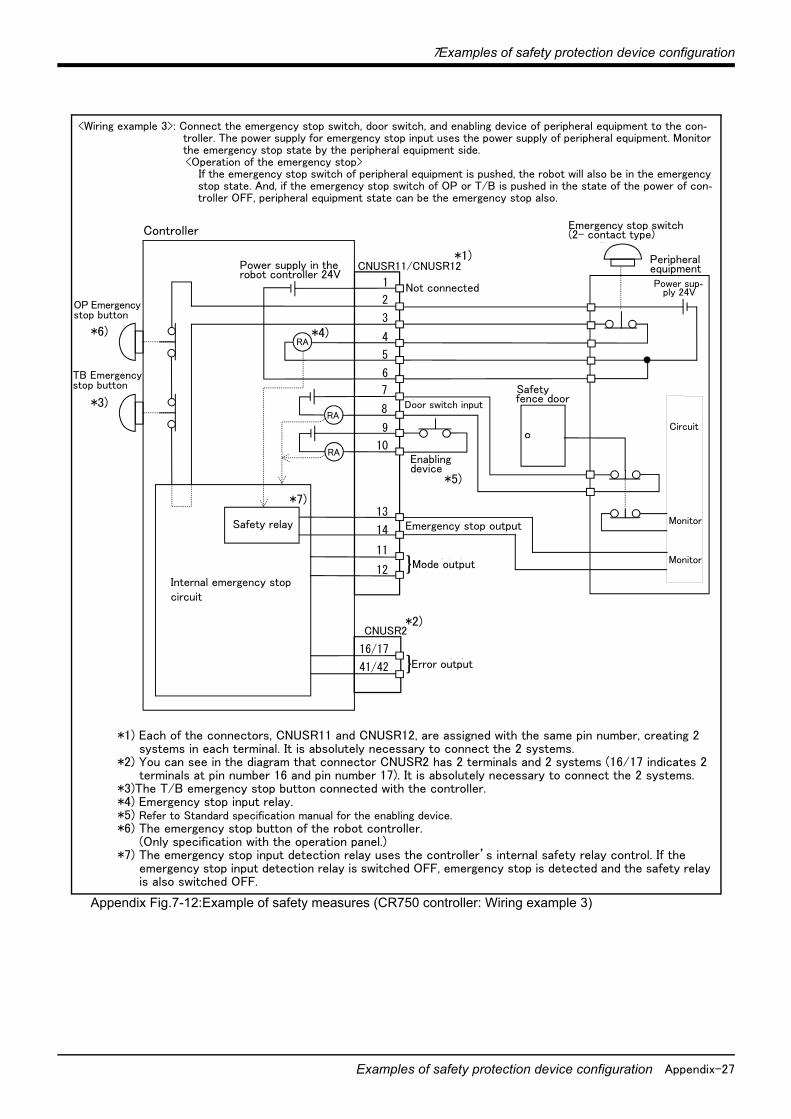
7Examples of safety protection device configuration
Examples of safety protection device configuration Appendix-27
Appendix Fig.7-12:Example of safety measures (CR750 controller: Wiring example 3)
<Wiring example 3>: Connect the emergency stop switch, door switch, and enabling device of peripheral equipment to the con-troller. The power supply for emergency stop input uses the power supply of peripheral equipment. Monitor the emergency stop state by the peripheral equipment side.<Operation of the emergency stop>
If the emergency stop switch of peripheral equipment is pushed, the robot will also be in the emergency stop state. And, if the emergency stop switch of OP or T/B is pushed in the state of the power of con-troller OFF, peripheral equipment state can be the emergency stop also.
非常停止スイッチ(2接点タイプ)
周辺装置
安全柵のドア
周辺装置側電源24V
監視
周 辺 装 置 側 内 部 回 路
CNUSR2
内部非常停止回路
未接続
非常停止出力
モード出力
RA
RA
RA
}
ドアスイッチ入力
イネーブリングデバイス
16/17
41/42 エラー出力}
監視
1
CNUSR11/CNUSR12
2
3
4
5
6
7
8
9
10
13
14
11
12
OP非常停止ボタン
TB非常停止ボタン
内部電源 24V
安全リレー
Controller
*1) Each of the connectors, CNUSR11 and CNUSR12, are assigned with the same pin number, creating 2 systems in each terminal. It is absolutely necessary to connect the 2 systems.
*2) You can see in the diagram that connector CNUSR2 has 2 terminals and 2 systems (16/17 indicates 2 terminals at pin number 16 and pin number 17). It is absolutely necessary to connect the 2 systems.
*3)The T/B emergency stop button connected with the controller.*4) Emergency stop input relay.*5) Refer to Standard specification manual for the enabling device.*6) The emergency stop button of the robot controller.
(Only specification with the operation panel.)*7) The emergency stop input detection relay uses the controller’s internal safety relay control. If the
emergency stop input detection relay is switched OFF, emergency stop is detected and the safety relay is also switched OFF.
Power supply in the robot controller 24V
OP Emergency stop button
TB Emergency stop button
Not connected
Door switch input
Enabling device
Mode output
Error output
Emergency stop outputSafety relay
Internal emergency stop circuit
Emergency stop switch (2- contact type)
Peripheral equipment
Safety fence door
Power sup-ply 24V
*1)
*2)
*3)
*6) *4)
*5)
*7)
Monitor
Monitor
Circuit

Appendix-28 Examples of safety protection device configuration
7Examples of safety protection device configuration
Appendix Fig.7-13:Example of safety measures (CR750 controller: Wiring example 4)
OP非常停止ボタン
TB非常停止ボタン
周辺装置の非常停止出力
周辺装置内部非常停止回路
周辺装置
非常停止スイッチ(4接点タイプ)
安全柵のドア
ドアスイッチ出力
監視
周辺装置の非常停止出力
周辺装置側電源24V
CNUSR2
内部非常停止回路
未接続
非常停止出力
モード出力
RA
RA
RA
}
ドアスイッチ入力
16/17
41/42 エラー出力}
監視
監視
CNUSR2
内部非常停止回路
未接続
非常停止出力
モード出力
RA
RA
RA
}
ドアスイッチ入力
16/17
41/42 エラー出力}
1
CNUSR11/CNUSR12
2
3
4
5
6
7
8
9
10
13
14
11
12
1
CNUSR11/CNUSR12
2
3
4
5
6
7
8
9
10
13
14
11
12
OP非常停止ボタン
TB非常停止ボタン
イネーブリングデバイス
イネーブリングデバイス
内部電源 24V
内部電源 24V
安全リレー
安全リレー
Controller #1
*5) Refer to Standard specification manual for the enabling device.*6) The emergency stop button of the robot controller. (Only specification with the operation panel.)*7) The emergency stop input detection relay uses the controller’s internal safety relay control. If the emergency stop input detection
relay is switched OFF, emergency stop is detected and the safety relay is also switched OFF.
Power supply in the robot controller 24V
OP Emer-gency stop button
TB Emer-gency stop button
Not connected
Enabling device
Mode output
Error output
Emergency stop outputSafety relay
Internal emergency stop circuit
Emergency stop switch (2- contact type)
Peripheral equipment
Safety fence door
Power supply 24V
*1)
*2)
*3)
*6)*4)
*5)*7)
Monitor
Monitor
Circuit
Door switch input
Not connected
<Wiring example 4>: Connect the emergency stop switch of peripheral equipment, and the door switch to two controllers, and it interlocks. Connect the enabling device to the robot controller.The power supply for emergency stop input uses the power supply of peripheral equipment. Monitor the emergency stop state by the peripheral equipment side.<Operation of the emergency stop>
If the emergency stop switch of peripheral equipment is pushed, the robot will also be in the emergency stop state. And, if the emergency stop switch of OP or T/B is pushed in the state of the power of con-troller OFF, peripheral equipment state can be the emergency stop also.
Monitor
Door switch input
Enabling device
Emergency stop output
Power supply in the robot controller 24V
Safety relay
TB Emer-gency stop button
*3)
OP Emer-gency stop button
*6)
Controller #2
*1) Each of the connectors, CNUSR11 and CNUSR12, are assigned with the same pin number, creating 2 systems in each terminal. It is absolutely necessary to connect the 2 systems.
*2) You can see in the diagram that connector CNUSR2 has 2 terminals and 2 systems (16/17 indicates 2 terminals at pin number 16 and pin number 17). It is absolutely necessary to connect the 2 systems.
*3) The T/B emergency stop button connected with the controller.*4) Emergency stop input relay.
Mode output
Error output
Internal emergency stop circuit
*1)
*2)
*7)
*4)
*5)

7Examples of safety protection device configuration
Examples of safety protection device configuration Appendix-29
Appendix Fig.7-14:Example of safety measures (CR750 controller: Wiring example 5)
OPE-stop
1
2
3
4
5
6
CNUSR11
内部リレー
TBE-stop
24G
1
2
3
4
5
624G
内部リレー
T12
T11
T22
T21
No connection
No connection
安全入力1
安全入力2
24V DC 24G
例)オムロン社 G9SX-AD
安全リレー
お客様電源(DC 24V)
A1 A2
お客様装置
24V DC
外部非常停止スイッチ
13
14
24V DC
24V DC
外部非常停止スイッチ
13
14
24V DC
安全リレー
非常停止出力
非常停止出力
CNUSR12
No connection
No connection
Controller
Safety relay
*2)
<Wiring example 5>: Connect the controller to the safety relay Use the controller’s emergency stop button command as an input to the safety relay.
Internal relay
Emergency stop output
Internal relay
External emergency stop switch
External emergency stop switch
Emergency stop output
Customer equipment
Safety relay
ex)
G9SX-AD series *OMRON
Safety input 1
Safety input 2
Customer Power Supply (DC 24V)
[Caution]
1) This product has category 3 functionality and therefore the robot’s whole unit cannot be set to category 4.2) The controller’s internal circuit has polarity. Please adhere to the polarity as detailed in the wiring examples,
particularly for emergency stop button output when using user equipment. Connect the positive side of the user equipment (24V DC) to the terminal 2 of CNUSR11/12, then connect the emergency stop button (or contact points) in the user equipment to across the terminals 3 and 4 of CNUSR11/12, and ultimately con-nect the negative side (24G).
3) When installing a safety relay to use it as an input point of the controller's emergency stop button command, use a safety relay that is activated by an input from one of the two systems (i.e. Omron’s G9S Series).
4) The emergency stop input detection relay (internal relay) uses the controller’s internal safety relay control. If the emergency stop input detection relay is switched OFF, emergency stop is detected and the safety relay is also switched OFF.
5) When connecting emergency stop button output to an external safety relay, please take note of the polarity and make sure that the electrical current flows in the same direction as indicated by the dotted arrows in the two places in the diagram. If the polarity is setup incorrectly, this function will not operate correctly. Please connect the terminal 13 of CNUSR11/12 to 24V.

Appendix-30 Examples of safety protection device configuration
7Examples of safety protection device configuration
(4) Examples of safety protection device configuration (CR751 series)Two emergency-stop input circuits are prepared on the user wiring terminal block of the controller. (Appen-dix Fig. 7-15)Create a circuit as shown below for safety measures. (Appendix Fig. 7-17 to Appendix Fig. 7-21) In addition, the figure shows the normal state which is not in the emergency stop state.
[Note] ・In the emergency-stop related wiring by the customer, if the coil (is not the contact points) of the relay prepared by the customer is connected to the controller, please be sure to implement the measure against the noise by the customer in the coil section. And, please also take the lifetime of noise suppression parts into consideration.
・Electric specification of the emergency-stop-related output terminal : 24Vdc/100mA or less
Appendix Fig.7-15:External emergency stop connection (CR751 controller)
Place the emergency stop switch in an easily operable position, and be sure to wire it to the emergency stop correctly by referencing Appendix Fig. 7-17 to Appendix Fig. 7-21.This is a necessary measure in order to ensure safe operation so that the robot can be stopped immediately by pressing the emergency stop switch in the event that the robot malfunctions.
CNUSR1
CNUSR2
内部回路構成(お客様配線側) (コントローラ側)
警告 絶縁耐圧試験は行なわないでください。また誤って接続した場合は故障の原因となります。
CNUSR1+24V
Relay
+24V
24G
24G
24G
RA+24V
RelayRA
RelayRA
外部非常停止入力
ドアスイッチ入力
イネーブリングデバイス入力
TB非常停止
+24V
Relay
+24V
24G
24G
24G
RA+24V
RelayRA
RelayRA
43
18
17
41
16
モード出力
非常停止出力
ロボットエラー出力外部非常停止入力
ドアスイッチ入力
イネーブリングデバイス入力
(お客様配線側)
短絡
短絡
短絡
短絡
モード出力
非常停止出力
ロボットエラー出力
44
19
42
17
20
45 27
28
4
29
5
30
3
2
1
26
32
33
9
34
35
8
7
6
31
10
Please refer to the example of safety measures of "Standard Specifications Manual".
Please do not carry out an insulation pressure test.Moreover, it becomes the cause of failure if it connects incorrectly.
CAUTION
Internal circuit structure(Controller side) (Customer)
Mode output
Mode output
Robot error output
Robot error output
Emergency stop output
Emergency stop output
Short
External emergency stop input
Short
Door switch input
Enabling device input
Short
External emergency stop input
Short
Door switch input
Enabling device input
TB emergency stop
(Customer)
*1) This terminal is opened at factory shipping (unconnected). If power supply inside the controller is used, short-circuit the terminal.
*1)
*1)
*1)
*1)
[Note] In the customer's system, do not ground the + side of 24V power supply prepared by customer for connect to the con-troller. (related with emergency stop and parallel input/output) If it connects with the controller under the condition that the + side is grounded, it will lead to failure of controller.
CAUTION

7Examples of safety protection device configuration
Examples of safety protection device configuration Appendix-31
Appendix Fig.7-16:Method of wiring for external emergency stop connection (CR751 controller (CNUSR1/2))
When soldering please take care to only connect to the specified pin number. Connecting to a different pin number or short-circuiting with another pin will result in the robot breaking down or malfunctioning.The connectors on the controller side are CNUSR1 (upper side) and CNUSR2 (lower side). Makes sure that there is no mistake when connecting to the target connectors. Connecting incorrectly will result in the robot breaking down or malfunctioning.
CNUSR1
CNUSR2
3mm
A
View APlugConnector cover
Connecting cable
(AWG #30 ~ #24(0.05mm ~ 0.2mm2))
Cover fixing screw (Two places)
Remove the connector cover
Pin number of plug25 1
50 26
SolderingConnector for user wiring
<CR751 controller>CNUSR1/2 connector
Connection procedureSolder the user wiring connector that accompanies the product to the corresponding pin, and connect it to the CNUSR1 or CNUSR2 connector at the back of the controller. For the connection cable, please use AWG #30 to 24
(0.05 to 0.2mm2).
1) Loosen the 2 fixing screws on the user wiring connector that accompanies the product, and remove the con-nector cover.
2) Peel the insulation of the connecting cable to 3mm, and solder it the appropriate connector pin number.3) After the necessary cable has been soldered, re-fix the connector cover sing the same fixing screws and make
sure it is fastened securely.4) Connect the connector to the corresponding connector (CNUSR1 or CNUSR2) on the controller. With pin num-
ber 1 facing to the upper right, insert firmly until you hear the connector’s latch click in to place.
This concludes the connection procedure.
CAUTION

Appendix-32 Examples of safety protection device configuration
7Examples of safety protection device configuration
Appendix Fig.7-17:Example of safety measures (CR751 controller: Wiring example 1)
非常停止スイッチ(2接点タイプ)
周辺装置
安全柵のドア
1/ 6
CNUSR1
CNUSR2
内部非常停止回路
コントローラ
非常停止出力
モード出力
TB非常停止ボタン
RA
RA
RA
}
ドアスイッチ入力
イネーブリングデバイス
26/31
2/ 7
27/32
3/ 8
28/33
4/ 9
29/34
5/10
30/35
20/19
45/44
18/17
43/42
16/17
41/42 エラー出力}
短絡
短絡
}安全リレー
内部電源 24V
<Wiring example 1>: Connect the emergency stop switch of peripheral equipment to the controller. The power supply for emergency stop input uses the power supply in the controller.<Operation of the emergency stop>
If the emergency stop switch of peripheral equipment is pushed, the robot will also be in the emergency stop state.
Controller
*1) Each of the connectors, CNUSR1 and CNUSR2, are assigned with the same pin number, creating 2 systems in each terminal. It is absolutely necessary to connect the 2 systems.
*2) The T/B emergency stop button connected with the controller.*3) Emergency stop input relay.*4) Refer to Standard specification manual for the enabling device.*5) The emergency stop input detection relay uses the controller’s internal safety relay control. If the
emergency stop input detection relay is switched OFF, emergency stop is detected and the safety relay is also switched OFF.
Power supply in the robot controller 24V
TB Emergency stop button
Not connected
Door switch input
Enabling device
Mode output
Error output
Emergency stop outputSafety relay
Internal emergency stop circuit
Emergency stop switch (2- contact type)
Peripheral equipment
Safety fence door
*1)
*1)
*4)
Short circuit(Short-circuited)
*2)
*3)
*5)
*6)

7Examples of safety protection device configuration
Examples of safety protection device configuration Appendix-33
Appendix Fig.7-18:Example of safety measures (CR751 controller: Wiring example 2)
非常停止スイッチ(2接点タイプ)
周辺装置
安全柵のドア
周辺装置側電源24V
1/ 6
CNUSR1
CNUSR2
内部非常停止回路
コントローラ
未接続
非常停止出力
モード出力
TB非常停止ボタン
RA
RA
RA
}
ドアスイッチ入力
イネーブリングデバイス
26/31
2/ 7
27/32
3/ 8
28/33
4/ 9
29/34
5/10
30/35
16/17
41/42 エラー出力}
}20/19
45/44
18/17
43/42
安全リレー
内部電源 24V
<Wiring example 2>: Connect the emergency stop switch of peripheral equipment to the controller. The power supply for emergency stop input uses the power supply of peripheral equipment. <Operation of the emergency stop>
If the emergency stop switch of peripheral equipment is pushed, the robot will also be in the emergency stop state.
Controller
Power supply in the robot controller 24V
TB Emergency stop button
Not connected
Door switch input
Enabling device
Mode output
Error output
Emergency stop outputSafety relay
Internal emergency stop circuit
Emergency stop switch (2- contact type)
Safety fence door
Power supply in the Peripheral equipment 24V
*1)
*1)
*3)
*4)
*5)
Peripheral equipment
*1) Each of the connectors, CNUSR1 and CNUSR2, are assigned with the same pin number, creating 2 systems in each terminal. It is absolutely necessary to connect the 2 systems.
*2) The T/B emergency stop button connected with the controller.*3) Emergency stop input relay.*4) Refer to Standard specification manual for the enabling device.*5) The emergency stop input detection relay uses the controller’s internal safety relay control. If the
emergency stop input detection relay is switched OFF, emergency stop is detected and the safety relay is also switched OFF.
*6) Connect the 24V power supply to 26/31 terminals.
*2)
*6)

Appendix-34 Examples of safety protection device configuration
7Examples of safety protection device configuration
Appendix Fig.7-19:Example of safety measures (CR751 controller: Wiring example 3)
非常停止スイッチ(2接点タイプ)
周辺装置
安全柵のドア
周辺装置側電源24V
監視
周 辺 装 置 側 内 部 回 路
1/ 6
CNUSR1
CNUSR2
内部非常停止回路
コントローラ
未接続
非常停止出力
モード出力
TB非常停止ボタン
RA
RA
RA
}
ドアスイッチ入力
イネーブリングデバイス
26/31
2/ 7
27/32
3/ 8
28/33
4/ 9
29/34
5/10
30/35
16/17
41/42 エラー出力}
20/19
45/44
18/17
43/42監視
安全リレー
内部電源 24V
Controller
Power supply in the robot controller 24V
TB Emergency stop button
Not connected
Door switch input
Enabling device
Mode output
Error output
Emergency stop outputSafety relay
Internal emergency stop circuit
Emergency stop switch (2- contact type)
Safety fence door
Power supply 24V
*1)
*1)
*3)
*4)
*5)
Peripheral equipment
*1) Each terminal assigned with the respectively same pin number as connector: CNUSR1 and CNUSR2 and each is dual line. Always connect the two lines.
*2) The T/B emergency stop button connected with the controller.*3) Emergency stop input relay.*4) Refer to Standard specification manual for the enabling device.*5) The emergency stop input detection relay uses the controller’s internal safety relay control. If the
emergency stop input detection relay is switched OFF, emergency stop is detected and the safety relay is also switched OFF.
*6) Connect the 24V power supply to 26/31 terminals.
*2)
*6)
<Wiring example 3>: Connect the emergency stop switch, door switch, and enabling device of peripheral equipment to the con-troller. The power supply for emergency stop input uses the power supply of peripheral equipment. Monitor the emergency stop state by the peripheral equipment side.<Operation of the emergency stop>
If the emergency stop switch of peripheral equipment is pushed, the robot will also be in the emergency stop state. And, if the emergency stop switch of OP or T/B is pushed in the state of the power of con-troller OFF, peripheral equipment state can be the emergency stop also.
Monitor
Monitor
Circuit

7Examples of safety protection device configuration
Examples of safety protection device configuration Appendix-35
Appendix Fig.7-20:Example of safety measures (CR751 controller: Wiring example 4)
周辺装置の非常停止出力
周辺装置内部非常停止回路
周辺装置
非常停止スイッチ(4接点タイプ)
安全柵のドア
ドアスイッチ出力
監視
周辺装置の非常停止出力
周辺装置側電源24V
1/ 6
CNUSR1
CNUSR2
内部非常停止回路
コントローラ #1
未接続
非常停止出力
モード出力
TB非常停止ボタン
RA
RA
RA
}
内部電源 24V
ドアスイッチ入力
イネーブリングデバイス
26/31
2/ 7
27/32
3/ 8
28/33
4/ 9
29/34
5/10
30/35
16/17
41/42 エラー出力}
監視
監視
1/ 6
CNUSR1
CNUSR2
内部非常停止回路
コントローラ #2
未接続
非常停止出力
モード出力
TB非常停止ボタン
RA
RA
RA
}
ドアスイッチ入力
イネーブリングデバイス
26/31
2/ 7
27/32
3/ 8
28/33
4/ 9
29/34
5/10
30/35
16/17
41/42 エラー出力}
20/19
45/44
18/17
43/42
20/19
45/44
18/17
43/42
安全リレー
安全リレー
内部電源 24V
Controller #1
Power supply in the robot controller 24V
TB emer-gency stop button
Not connected
Door switch input
Enabling device
Mode output
Error output
Emergency stop output
Safety relay
Internal emergency stop circuit
Emergency stop switch (2- contact type)
Safety fence door
Power supply 24V
*1)
*1)
*3)
*4)
*5)
Peripheral equipment
*3) Emergency stop input relay.*4) Refer to Standard specification manual for the enabling device.*5) The emergency stop input detection relay uses the controller’s internal safety relay control. If the emergency stop input detection
relay is switched OFF, emergency stop is detected and the safety relay is also switched OFF.
*2)
Monitor
Monitor
<Wiring example 4>: Connect the emergency stop switch of peripheral equipment, and the door switch to two controllers, and it interlocks. Connect the enabling device to the robot controller.The power supply for emergency stop input uses the power supply of peripheral equipment. Monitor the emergency stop state by the peripheral equipment side.<Operation of the emergency stop>
If the emergency stop switch of peripheral equipment is pushed, the robot will also be in the emergency stop state. And, if the emergency stop switch of OP or T/B is pushed in the state of the power of con-troller OFF, peripheral equipment state can be the emergency stop also.
*1)
*1)
Controller #2
TB emer-gency stop button
*2)
Power supply in the robot controller 24V
Not connected
Door switch input
Mode output
Error output
Safety relay
*5)
Internal emergency stop circuit
Enabling device
*4)
Emergency stop output
Circuit
Monitor
*3)
*1) Each of the connectors, CNUSR1 and CNUSR2, are assigned with the same pin number, creating 2 systems in each terminal. It is absolutely necessary to connect the 2 systems.
*2) The T/B emergency stop button connected with the controller.
*3)

Appendix-36 Examples of safety protection device configuration
7Examples of safety protection device configuration
Appendix Fig.7-21:Example of safety measures (CR751 controller: Wiring example 5)
OPE-stop
1
26
2
27
3
28
CNUSR1
内部リレー
TBE-stop
24G
6
31
7
32
8
3324G
内部リレー
T12
T11
T22
T21
No connection
No connection
安全入力1
安全入力2
24V DC 24G
例)オムロン社 G9SX-AD
安全リレー
お客様電源(DC 24V)
A1 A2
お客様装置
24V DC
外部非常停止スイッチ
20
45
24V DC
24V DC
外部非常停止スイッチ
19
44
24V DC
安全リレー
非常停止出力
非常停止出力
No connection
No connection
Controller
<Wiring example 5>: Connect the controller to the safety relay Use the controller’s emergency stop button to input safety relay.
Safety relay
Internal relay
Emergency stop output
External emergency stop switch
Customer equipment
Safety relay
ex)
G9SX-AD series *OMRON
Customer Power Supply (DC 24V)
Internal relay
Emergency stop output
External emergency stop switch
Safety input 1
Safety input 2
[Caution]
1) This product has category 3 functionality and therefore the robot’s whole unit cannot be set to category 4.2) The controller’s internal circuit has polarity. Please adhere to the polarity as detailed in the wiring examples,
particularly for emergency stop button output when using user equipment. Connect the positive side of the user equipment (24V DC) to the two terminals 26/31, then connect the emergency stop button (or contact points) in the user equipment to the 2-27 and 7-32 terminals, and ultimately connect to the negative side (24G).
3) Setup a safety relay on the user equipment, and when using to input the emergency stop button on the con-troller, please only use a safety relay that functions when connecting the input to the one end of the 2 sys-tems (i.e. Omron’s G9S Series).
4) The emergency stop input detection relay (internal relay) uses the controller’s internal safety relay control. If the emergency stop input detection relay is switched OFF, emergency stop is detected and the safety relay is also switched OFF.
5) When connecting emergency stop button output to an exterior safety relay, please take note of the polarity and make sure that the electrical current flows in the same direction as indicated by the dotted arrows in the two places in the diagram. If the polarity is setup incorrectly this function will not operate correctly. Please connect 20/19 terminal to 24V.


Mar., 2014 MEE Printed in Japan on recycled paper. Specifications are subject to change without notice.
HEAD OFFICE: TOKYO BUILDING, 2-7-3, MARUNOUCHI, CHIYODA-KU, TOKYO 100-8310, JAPANNAGOYA WORKS: 5-1-14, YADA-MINAMI, HIGASHI-KU, NAGOYA 461-8670, JAPAN
Authorised representative:
MITSUBISHI ELECTRIC EUROPE B.V. GERMANY
Gothaer Str. 8, 40880 Ratingen / P.O. Box 1548, 40835 Ratingen, Germany