mitigation of power quality issues using integrated dvr...
TRANSCRIPT
386 G Siva Rama Krishna, K Narasimha Rao
International Journal of Engineering Technology Science and ResearchIJETSR
www.ijetsr.comISSN 2394 – 3386
Volume 4, Issue 10October 2017
Mitigation of Power Quality Issues using Integrated DVR withUltra Capacitor in Distribution Grid
G Siva Rama Krishna, K Narasimha Rao,Gayatri Vidya Parishad College of Engineering (Autonomous)
Visakhapatnam, India.
ABSTRACTPower Quality is the major concern in case of sensitive loads that are present in Distribution System. DVR is one of theFACTS devices to improve power quality. The conventional DVR consist of batteries and bi-directional converter. In thisproposed work DVR’s life time is improved, by replacing battery with Ultra capacitor. Ultra Capacitors are mostsuitable for short duration of energy requirements i.e. for compensation of sags and swells. A buck-boost converterhasbeen used for integrating the Ultra Capacitor to DVR system. In this paper a Voltage feedback PI-controller has beendeveloped, for generating the gate pulses to inverter. In addition to this an average current mode controller is used forcontrolling the buck boost converter which is a robust controller for boosting and bucking the DC voltage levels. An in-phase injection method is used in DVR for compensating the voltage sags and swells.
Simulation and analysis of integrated ‘DVR with UCAP’, and ‘DVR with battery’ for different duration of voltagesags/swells are performed in PSCAD software. The corresponding active power, reactive power, voltages, and currents,are observed. From the simulation results, it is concluded that the ‘DVR with UCAP’ gives better performance than‘DVR with battery’ in terms of speed of response.Keywords
Ultra Capacitor (UCAP), Dynamic Voltage Restorer (DVR), Voltage Sag, Power Quality Issues, Distribution Grid(DG).
I. INTRODUCTIONThe percentage of sensitive loads is increasing day-by-day, which creates the need for the power quality.Faults and sudden demand variations are common in distribution system. Voltage sags and swells are one ofthe power quality issues. Faults on one feeder, the adjacent feeders experience the sags (or) swells and suddendemand variations also create the sags/swells. Which may degrade the equipment performance; sometimes itdamages the equipment’s. FACTS devices are used to improve the power quality.STATCOM and DVR are the two devices most often used in the power system network to compensate thevoltage sags and swells. Particularly for three phase sensitive loads in low voltage distribution side DVR ismost popular, because it is connected in series to the particular load, and it directly nullifies the voltageharmonics by injecting voltage into feeder.
DVR is a solid state power electronic device which is connected in series with the system. and is used tocompensate the Voltage sags, swells, and harmonics.
Principle and operation: DVR works on the principle of injecting the voltage in series with system voltage.The operation of DVR is explained in two modes Mode (1): In this mode, DVR injects voltage into system,which is opposite in- phase with the system voltage and battery/UCAP is in charging, this case will happenwhen there is swell in the system Mode (2): In this mode DVR injects the voltage into system which in- phasewith the system voltage and Inverter starts discharging the battery/UCAP, this case will happen when there asag in the system.
In this project, life time of DVR is increased by connecting the Ultra capacitor in place of battery. Sinceconventional DVR consist of battery storage with an inverter, because of battery low power density, it isslowly charging but short duration of voltage sags required fast charging and the lifecycle of battery is less. To
387 G Siva Rama Krishna, K Narasimha Rao
International Journal of Engineering Technology Science and ResearchIJETSR
www.ijetsr.comISSN 2394 – 3386
Volume 4, Issue 10October 2017
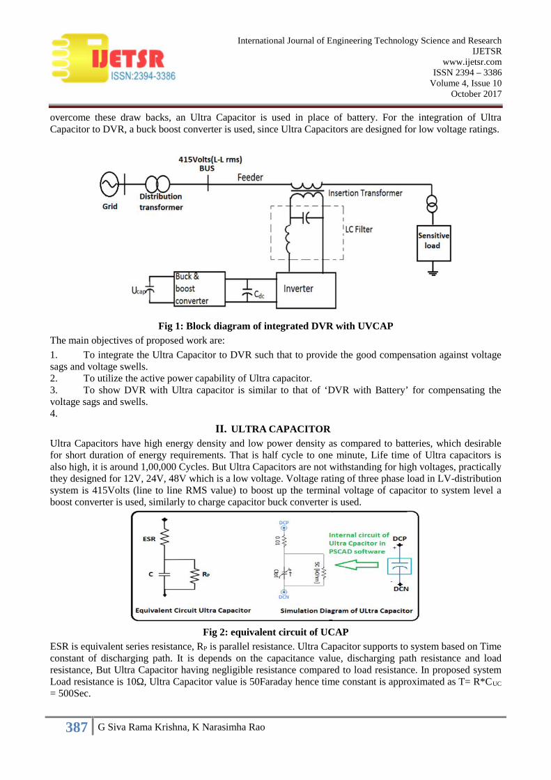
overcome these draw backs, an Ultra Capacitor is used in place of battery. For the integration of UltraCapacitor to DVR, a buck boost converter is used, since Ultra Capacitors are designed for low voltage ratings.
Fig 1: Block diagram of integrated DVR with UVCAPThe main objectives of proposed work are:
1. To integrate the Ultra Capacitor to DVR such that to provide the good compensation against voltagesags and voltage swells.2. To utilize the active power capability of Ultra capacitor.3. To show DVR with Ultra capacitor is similar to that of ‘DVR with Battery’ for compensating thevoltage sags and swells.4.
II. ULTRA CAPACITORUltra Capacitors have high energy density and low power density as compared to batteries, which desirablefor short duration of energy requirements. That is half cycle to one minute, Life time of Ultra capacitors isalso high, it is around 1,00,000 Cycles. But Ultra Capacitors are not withstanding for high voltages, practicallythey designed for 12V, 24V, 48V which is a low voltage. Voltage rating of three phase load in LV-distributionsystem is 415Volts (line to line RMS value) to boost up the terminal voltage of capacitor to system level aboost converter is used, similarly to charge capacitor buck converter is used.
Fig 2: equivalent circuit of UCAPESR is equivalent series resistance, RP is parallel resistance. Ultra Capacitor supports to system based on Timeconstant of discharging path. It is depends on the capacitance value, discharging path resistance and loadresistance, But Ultra Capacitor having negligible resistance compared to load resistance. In proposed systemLoad resistance is 10Ω, Ultra Capacitor value is 50Faraday hence time constant is approximated as T= R*CUC
= 500Sec.

388 G Siva Rama Krishna, K Narasimha Rao
International Journal of Engineering Technology Science and ResearchIJETSR
www.ijetsr.comISSN 2394 – 3386
Volume 4, Issue 10October 2017
III. BUCK BOOST CONVERTERBuck boost converter is a bidirectional device. this DC to DC to converter act as a Buck converter in onedirection and boost converter in another direction, DC link voltage designed and Maintained constant at 500volts.
This DC to DC converter operated in two modes:
Buck mode: In this mode the DC-link voltage 500volts is step down to Ultra Capacitor terminal voltage thatis 200volts. To step down the voltage, switch S2, and diode D2 will operate. The duty ratio of buck converter iscalculated as D = VUC /VDC = 200/500 = 0.4
Boost mode: In this mode Ultra capacitor voltage 200 volts is step up to DC-link voltage that is 500 volts. Tostep up the voltage switch S1 and diode D2 will operate. The duty ratio of boost converter is calculated asDBOOST = (VDC- VUC)/VDC = 0.6.
Fig 3: Circuit diagram of Buck boost converterBy considering the state variables as Inductor current (IL) and DC-link voltage (VDC) controller is developed.Hence inductor current (IL) and DC-link voltage (VDC) are the feedback parameters for the controller, and thiscontroller is an Average current mode controller which is widely explored in ref [2]. This controller consistsof Voltage compensator and followed by current compensator, which are shown in fig 3.
Fig 4: Average current mode controllerThe proportional and integral gain values of PI-controller of voltage and current compensator of Averagecurrent mode controller is explained in ref[2].
IV. BIDIRECTIONAL CONVERTERThis is a bidirectional converter, whenever Battery /UCAP charging, it will act as a rectifier and fordischarging, it will act as an Inverter. IGBT with anti-parallel body Diodes are used in the converter which isshown in fig 5 and its operational is explained in the below.

389 G Siva Rama Krishna, K Narasimha Rao
International Journal of Engineering Technology Science and ResearchIJETSR
www.ijetsr.comISSN 2394 – 3386
Volume 4, Issue 10October 2017
In fig 8 VDC is the DC-link voltage, CDC is the DC-link Capacitor which is used to remove ripple in DC-linkvoltages. In swell operation battery/UCAP is charging then converter diodes D1 to D6 will act as a rectifier.Similarly for compensation of sags, inverter will operate and injects voltage in phase with the system voltage.In this work three single phase H-bridge converters are used, it inject the voltage into system, three singlephase transformers are used, that are shown in fig 8, the turn’s ratio of these transformers is 1:1.Typical ratings of Transformers used in the Distribution system are varies between 10KVA to 100KVA.Generally these transformers are liquid cooling and made up of amorphous core.
Primary winding of series transformers connected in series with the line and secondary winding oftransformers either we connect in star or delta.
In DVR low pass filters are used to eliminate harmonics caused by converter circuit. The filter inductance andcapacitance are calculated by using the formula.
F F
1f =
2Π * L C
Where F is the design frequency that should be allowed through the filter
LF is the inductance of filter
CF is the filter capacitance
V. INVERTER CONTROLLERDifferent types controllers are used to control the DVR inverter based on the feedback, forward paths. In thisproposed work PI-controller is used to control the inverter which is robust and more versatile controller. abcto dq0 (perks transformation) conversion is used to generate the reference signals. Fig 6 shows the basic blockdiagram of proposed control scheme.
Inverter controller consists of four components, which are:
1) PLL (Phase Locked Loop)2) Reference signal generation (inverse parks-transformation)3) PI controller4) Pulse generator with SPWMPLL are used to estimate the phase angle of the source voltage signals and which is used to generate thereference signal for the controller. To generate the reference signal inverse park transformation is used; that isby considering the quadrature component Vq = 338volts direct axis component Vd = 0 volts and zero sequencecomponent directly taken from the supply phase voltages to consider the unbalances.
Fig 6: block diagram of inverter controllerInverter controller is a feedback controller which is PI controller using inverse parks transformation. Inverteroutput voltage is controlled, and then this controller is named as voltage feedback controller.
390 G Siva Rama Krishna, K Narasimha Rao
International Journal of Engineering Technology Science and ResearchIJETSR
www.ijetsr.comISSN 2394 – 3386
Volume 4, Issue 10October 2017
VI. SIMULATION OF INTEGRATED ‘DVR WITH UCAP’The simulation of the ‘DVR with UCAP’ is carried out in PSCAD (4.6v) software.System Description:Consider a Distribution system single feeder supplied by a Distribution grid through a distributiontransformer, and DVR connecting in series to the load with the series transformer with passive filter which isshown in fig 8. The design parameters of the system are presented in Table 1.
Based on rated parameters of the distribution system, voltage ripple of DC-link is set to 5% thencorresponding values of Buck boost converter is calculated.
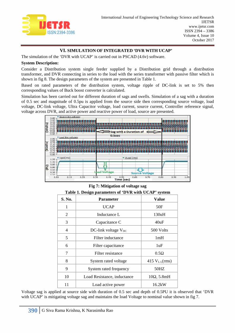
Simulation has been carried out for different duration of sags and swells. Simulation of a sag with a durationof 0.5 sec and magnitude of 0.5pu is applied from the source side then corresponding source voltage, loadvoltage, DC-link voltage, Ultra Capacitor voltage, load current, source current, Controller reference signal,voltage across DVR, and active power and reactive power of load, source are presented.
Fig 7: Mitigation of voltage sagTable 1. Design parameters of ‘DVR with UCAP’ system
S. No. Parameter Value
1 UCAP 50F
2 Inductance L 130uH
3 Capacitance C 40uF
4 DC-link voltage VDC 500 Volts
5 Filter inductance 1mH
6 Filter capacitance 1uF
7 Filter resistance 0.5Ω
8 System rated voltage 415 VL-L(rms)
9 System rated frequency 50HZ
10 Load Resistance, inductance 10Ω, 5.8mH
11 Load active power 16.2kW
Voltage sag is applied at source side with duration of 0.5 sec and depth of 0.5PU it is observed that ‘DVRwith UCAP’ is mitigating voltage sag and maintains the load Voltage to nominal value shown in fig 7.

391 G Siva Rama Krishna, K Narasimha Rao
International Journal of Engineering Technology Science and ResearchIJETSR
www.ijetsr.comISSN 2394 – 3386
Volume 4, Issue 10October 2017
Fig 9 shows the voltage across DVR, during Sag voltage across DVR is 200volts which is injected into thesystem. Fig 10 and fig 11 are the voltages of DC-link and terminal voltage of the UCAP, which are almostconstant.
Fig 8: circuit diagram of integrated ‘DVR with UCAP’
Fig 9: voltage across DVR during sag
Fig 10: DC-link voltage
392 G Siva Rama Krishna, K Narasimha Rao
International Journal of Engineering Technology Science and ResearchIJETSR
www.ijetsr.comISSN 2394 – 3386
Volume 4, Issue 10October 2017
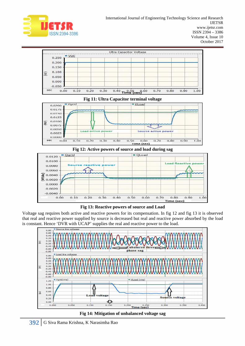
Fig 11: Ultra Capacitor terminal voltage
Fig 12: Active powers of source and load during sag
Fig 13: Reactive powers of source and LoadVoltage sag requires both active and reactive powers for its compensation. In fig 12 and fig 13 it is observedthat real and reactive power supplied by source is decreased but real and reactive power absorbed by the loadis constant. Hence ‘DVR with UCAP’ supplies the real and reactive power to the load.
Fig 14: Mitigation of unbalanced voltage sag

393 G Siva Rama Krishna, K Narasimha Rao
International Journal of Engineering Technology Science and ResearchIJETSR
www.ijetsr.comISSN 2394 – 3386
Volume 4, Issue 10October 2017
in fig 14, an Unbalanced sag is applied at PCC from 0.155sec to 0.355sec on source side, then correspondingvoltage across load is remains constant. From this figure it is observed that ‘DVR with UCAP’ is mitigatingthe Unbalanced Voltage Sag.
From the fig 15 it is observed that, voltage of the source is increased 1 to 1.5 PU but the ‘DVR with UCAP’ ismaintains the load voltage at remains at the 1.0PU.
Fig 15: Mitigation of voltage swellFig 16 shows voltage across DVR during swell, which is more compared to before and after swell, in samefigure one can see, that zoomed portion of graph shows voltage injected by DVR is an opposite In-phase tothe system voltage.
In fig 17 it is observed that the during voltage swell the active power supplied by source is more compared toload, but active power is absorbed by load is remains constant. The active power capability of DVR iscalculated by using the formula.
Fig 16: Voltage across DVR during swell

394 G Siva Rama Krishna, K Narasimha Rao
International Journal of Engineering Technology Science and ResearchIJETSR
www.ijetsr.comISSN 2394 – 3386
Volume 4, Issue 10October 2017
Fig 17: Active powers of source and Load diring swellSag applied in the simulation is having a magnitude of 0.5pu then active power supplied by DVR is PDVR = (1-0.5)16.2 = 8.1 kW this could be verified in the simulation results of ‘DVR with UCAP’.
PDVR = A*PLOAD (1)Where A is a constant that is given by:
A = (1-VS Cos (ϕ+α)/Cos (ϕ)) (2)One can neglect the phase angle jump α then
PDVR = B *PLOAD (3)Where B is a constant that is given by:
B = (1-VS) (4)Where: PDVR is the active power that can deliver or absorb by the DVR PLOAD is the active power absorbed by the load VS is the source voltage or rated System voltage on Per-Unit form Cos(ϕ) is the load power factor
α is the phase angle jump in the voltages whenever there is sag or swell and the typical value of these phaseangle jump is 150 degrees.
VII.SIMULATION OF ‘DVR WITH BATTERY’Simulation of ‘DVR with Battery’ has been performed in PSCAD (4.6v) software.
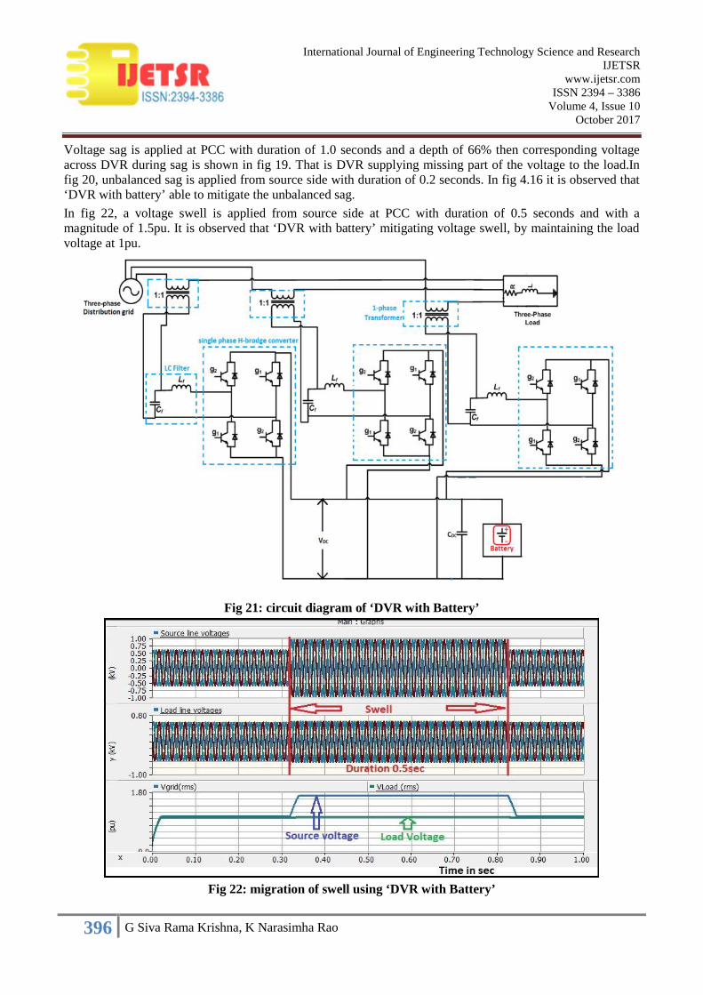
System Description: Consider a Distribution system single feeder supplied by a Distribution grid and DVR isconnected in series to the load with a series transformer and with passive filter. Table 2 shows the designparameters of the battery. Fig 21 shows the simulated model of ‘DVR with Battery’ and VDC is the DC-linkvoltage, CDC is the DC-link capacitor.
Table 2. Design parameters of ‘DVR with Battery’
S.NO: Design Parameters Values
1 Battery rating 60Amph
2 DC Capacitor CDC 3mF
3 Battery Voltage VB 480 Volts
395 G Siva Rama Krishna, K Narasimha Rao
International Journal of Engineering Technology Science and ResearchIJETSR
www.ijetsr.comISSN 2394 – 3386
Volume 4, Issue 10October 2017
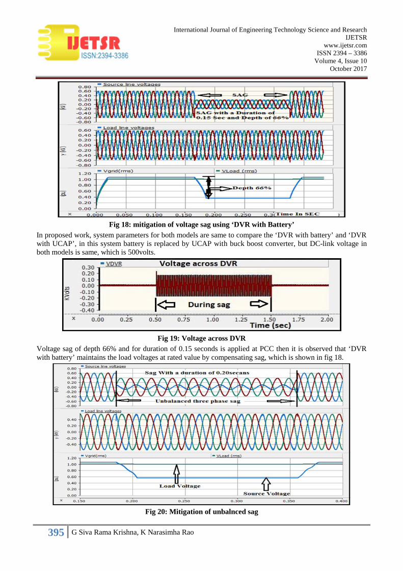
Fig 18: mitigation of voltage sag using ‘DVR with Battery’In proposed work, system parameters for both models are same to compare the ‘DVR with battery’ and ‘DVRwith UCAP’, in this system battery is replaced by UCAP with buck boost converter, but DC-link voltage inboth models is same, which is 500volts.
Fig 19: Voltage across DVRVoltage sag of depth 66% and for duration of 0.15 seconds is applied at PCC then it is observed that ‘DVRwith battery’ maintains the load voltages at rated value by compensating sag, which is shown in fig 18.
Fig 20: Mitigation of unbalnced sag
396 G Siva Rama Krishna, K Narasimha Rao
International Journal of Engineering Technology Science and ResearchIJETSR
www.ijetsr.comISSN 2394 – 3386
Volume 4, Issue 10October 2017
Voltage sag is applied at PCC with duration of 1.0 seconds and a depth of 66% then corresponding voltageacross DVR during sag is shown in fig 19. That is DVR supplying missing part of the voltage to the load.Infig 20, unbalanced sag is applied from source side with duration of 0.2 seconds. In fig 4.16 it is observed that‘DVR with battery’ able to mitigate the unbalanced sag.In fig 22, a voltage swell is applied from source side at PCC with duration of 0.5 seconds and with amagnitude of 1.5pu. It is observed that ‘DVR with battery’ mitigating voltage swell, by maintaining the loadvoltage at 1pu.
Fig 21: circuit diagram of ‘DVR with Battery’
Fig 22: migration of swell using ‘DVR with Battery’

397 G Siva Rama Krishna, K Narasimha Rao
International Journal of Engineering Technology Science and ResearchIJETSR
www.ijetsr.comISSN 2394 – 3386
Volume 4, Issue 10October 2017
Mitigation of harmonics:
Fig 23: Mitigation nonlinear voltages using ‘DVR with Battery’
Fig 24: Mitigation of nonlinear voltages using ‘DVR with UCAP’In the fig 23 it observed that ‘DVR with battery’ allows some harmonics (highlighted portion of graph withcircles shows spikes) in the load voltages. In the fig 24 it is observed that ‘DVR with UCAP’ completelyeliminates the harmonics present in PCC voltage. The performance ‘DVR with UCAP’ is better than ‘DVRwith Battery’, since load voltages are pure sinusoidal in fig 24. In case of ‘DVR with Battery’, THD of loadvoltages is 0.09% and for ‘DVR with UCAP’, THD is 0.01%.
VIII.CONCLUSIONIt is observed that ‘DVR with UCAP’ is able to mitigate both balanced and unbalanced sags (and) swells. The‘DVR with UCAP’ supplies the active and reactive powers to the load during sag and maintains the loadvoltage at the rated value (1perunit) which has been verified through simulation analysis. Similarly, it isobserved that the ‘DVR with UCAP’ absorbs the active and reactive powers during swell conditions and itmaintains the load voltage at rated value (1perunit), by injecting a voltage opposite in-phase to the systemvoltage.
It is also observed that capacitor voltage and DC-link voltage are almost constant. The ‘DVR with battery’and ‘DVR with UCAP’ are compared and observed that UCAP works similar to that of batter and for themitigation of harmonics, UCAP performs better than battery. Hence it is concluded that UCAP is one of theenergy storage device that perfectly fit for compensation of sags and swells.

398 G Siva Rama Krishna, K Narasimha Rao
International Journal of Engineering Technology Science and ResearchIJETSR
www.ijetsr.comISSN 2394 – 3386
Volume 4, Issue 10October 2017
IX. REFERENCES[1] Math H. J. Bollen,“Understanding power quality problems (voltage sags and interruptions)”, IEEE power
engineering society, e 2000 The Institute of Electrical and Electronics Engineers, INC. 3 Park Avenue, 17th Floor,New York,NY 10016-5997 Publishedby John Wiley & Sons, Inc., Hoboken, New Jersey.
[2] Deepak Somayajula, Member, IEEE, and Mariesa L. Crow, Fellow, IEEE “An Integrated Dynamic VoltageRestorer-Ultracapacitor Design for Improving Power Quality of the Distribution Grid” IEEE Transactions OnSustainable Energy, Vol. 6, No. 2, April 2015.
[3] Rakeshwri Pal, Dr. Sushma Gupta2, “State of the Art: Dynamic Voltage Restorer for Power Quality ImprovementElectrical & Computer Engineering” An International Journal (ECIJ), Volume 4, Number 2, June 2015.
[4] A. KhoshkbarSadigh, Student Member, IEEE, and K. M. Smedley, Fellow, IEEE “Review of Voltage CompensationMethods in Dynamic Voltage Restorer (DVR)” 2012 IEEE 978-1-4673-2729-9/12/$31.00 ©2012 IEEE.
[5] C. Abbey and G. Joos, “Super capacitor energy storage for wind applications”IEEE Trans. Ind. Appl., vol. 43, no.3, pp. 769–776, Jun. 2007.
[6] R. W. Erickson and D. Maksimovic, “Fundamentals of Power Electronics” 2nd ed. Norwell, MA, USA: Kluwer,2001.
[7] H. Akagi, E. H.Watanabe, and M. Aredes, “Instantaneous Reactive Power Theory and Applications to PowerConditioning”, 1st ed. Hoboken, NJ, USA: Wiley, Piscataway, NJ, USA: IEEE Press, 2007.
[8] N. H. Woodley, L. Morgan, and A. Sundaram, “Experience with an inverter-based dynamic voltage restorer,”IEEETrans. Power Del., vol. 14, no. 3, pp. 1181–1186, Jul. 1999.
[9] IEEE Standard 1159-2013, “IEEE Recommended Practices for Monitoring Electric Power Quality”. IEEEStandards Coordinating Committee 22 on Power Quality, The Institute of Electrical and Electronics Engineers, Inc.3 Park Avenue, New York, NY 10016-5997, USA
[10] P. F. Ribeiro, B. K. Johnson, M. L. Crow, A. Arsoy, and Y. Liu, “Energy storage systems for advanced powerapplications,”Proc. IEEE, vol. 89, no. 12, pp. 1744–1756, Dec. 2001
[11] Y. Li, Y. Wang, B. Zhang, and C. Mao, “Modeling and simulation of dynamic voltage restorer based onsupercapacitor energy storage”, in Proc. Int. Conf. Electric Mach. Syst. (ICEMS), 2008, pp. 2064–2066.
[12] P. R. Sanchez, E. Acha, J. E. O. Calderon, V. Feliu, and A. G. Cerrada, “A versatile control scheme for a dynamicvoltage restorer for power quality improvement,”IEEE Trans. Power Del., vol. 24, no. 1, pp. 277–284, Jan.2009.
[13] IEEE Std 519™-2014 (Revision of IEEE Std 519-1992) “IEEE Recommended Practice and Requirements forHarmonic Control in Electric Power Systems” IEEE Power and Energy Society IEEE 3 Park Avenue New York, NY10016-5997 USA
[14] IEEE Std 1250™-2011 (Revision of IEEE Std 1250-1995) “IEEE Guide for Identifying and Improving VoltageQuality in Power Systems” IEEE Power & Energy Society 3 Park Avenue New York, NY 10016-5997 USA 31March 2011.
[15] D. M. Vilathgamuwa, A. A. D. R. Perera, and S. S. Choi, “Voltage sag compensation with energy optimizeddynamic voltage restorer” IEEE Trans. Power Del., vol. 18, no. 3, pp. 928–936, Jul. 2003.