mitigating the negative impact of the stray flux on the ... · pdf filedifferential relay is...
TRANSCRIPT

Givi et al., Cogent Engineering (2016), 3: 1229087http://dx.doi.org/10.1080/23311916.2016.1229087
ELECTRICAL & ELECTRONIC ENGINEERING | RESEARCH ARTICLE
Mitigating the negative impact of the stray flux on the current transformers using flux equalizing windingsHadi Givi1*, Javad Shokrollahi Moghani1 and Haidar Samet2
Abstract: The accuracy of the current transformers (CTs) supplying the generator differential relay is essential in power plant stations. One important factor which decreases the CT accuracy is the stray flux originated from the adjacent phases. During external fault conditions, the currents of adjacent phases contain a consider-able decaying DC component. Thus, corresponding fluxes also contain a decaying DC component which cannot be counteracted by bus bar enclosure and generator shell, completely. Hence, the CT output signal deviates from the correct waveform which may lead to undesirable operation of the differential relay supplied by the CT. In fact, there is no internal fault in the generator but the differential relay trips the breaker due to negative impact of stray flux on CT accuracy. In this paper, a real power plant bus bar is modelled using three-Dimensional (3D) finite element meth-od. Then, the effect of the stray flux on the accuracy of the CTs is studied. Finally, flux equalizing windings are considered on the CT’s secondary winding. According to finite element simulation results, the negative impact of the stray flux on the CT accuracy is decreased considerably by the flux equalizing windings.
Subjects: Instrumentation; Measurement & Testing; Power Engineering; Technology
Keywords: current transformer; finite element method; generator differential protection; stray flux; flux equalizing windings
*Corresponding author: Hadi Givi, Department of Electrical Engineering, Amirkabir University of Technology, Tehran, Iran E-mail: [email protected]
Reviewing editor:Kun Chen, Wuhan University of Technology, China
Additional information is available at the end of the article
ABOUT THE AUTHORSHadi Givi received the BSc and MSc degrees in electrical power engineering from Isfahan University of Technology, Isfahan, Iran in 2010 and Amirkabir University of Technology, Tehran, Iran in 2012. Currently, he is working toward the PhD degree in electrical power engineering in Shiraz University, Shiraz, Iran. His main fields of interest are analyzing electromagnetic systems using FEM and fault diagnosis in power electronic converters.
Javad Shokrollahi Moghani is an associate professor at the Department of Electrical Engineering, Amirkabir University of Technology, Tehran, Iran. His research interests include electromagnetic system modeling and design using FEM, DC-DC converters, and electric drives.
Haidar Samet is an associate professor of School of Electrical and Computer Engineering at Shiraz University, Shiraz, Iran. His major research interests are protection and relaying, FACTS, power quality and electric arc furnaces.
PUBLIC INTEREST STATEMENTElectrical generators are considered as the main source of electrical energy in the world. As a result, different protection devices are utilized to protect them against faults. These devices are supplied by the generators’ voltage and current signals to monitor the generator status. These signals are obtained using sensors. Current transformers are the sensors utilized to measure the currents flowing in the generator conductors. However, their output signal may be affected by the stray flux which is an undesirable factor. This situation may lead to incorrect operation of the protection devices which in turn results in the generator disconnection from the electrical network. This research aims to analyze the performance of the current transformers in the presence of the stray flux. Finite element method is employed for analysis which is an efficient numerical technique. Furthermore, using flux equalizing windings is evaluated to mitigate the negative impact of the stray flux.
Received: 16 November 2015Accepted: 23 August 2016First Published: 26 August 2016
© 2016 The Author(s). This open access article is distributed under a Creative Commons Attribution (CC-BY) 4.0 license.
Page 1 of 19
Hadi Givi

Page 2 of 19
Givi et al., Cogent Engineering (2016), 3: 1229087http://dx.doi.org/10.1080/23311916.2016.1229087
1. IntroductionDue to increasing demand for electrical power, the generators in the power plants should be de-signed for high rates of power. Based on technical limitations, the generators output voltage cannot exceed 25 kV. So the rate of their output currents should be increased (Braun, 1977). These currents are measured using current transformers. The accuracy of the current transformer secondary signal under transient conditions is a challenge for protection schemes. The CT saturation and stray flux threaten correct operation of protective relays.
There have been many papers in the literature regarding transient performance of current trans-formers. The saturation of CT’s core under fault conditions has been discussed and the techniques for correction of CT transient performance have been listed (Wiszniewski, Rebizant, & Schiel, 2008). The accuracy of transformer differential protection is threatened by CT saturation since discrimination between internal fault currents and inrush current becomes difficult during saturation. An effective compensating algorithm has been proposed to reconstruct the CT distorted current by which dis-crimination between fault and inrush currents is possible (Hajipour, Vakilian, & Sanaye-Pasand, 2015). The method is simple and independent of power system topology. The effect of CT saturation on transformer differential protection has been investigated (Stanbury & Djekic, 2015). Considering the importance of CT accuracy for protection schemes, a method was proposed to tackle the problems caused by CT excitation current (Telino Meneses & Laurindo Maitelli, 2016). It was shown that the ratio and angle errors could be decreased through compensating the voltage drop in the CT second-ary by a simple control circuit. CT saturation leads to nuisance trips and it was shown that harmonic blocking achieves desirable security against these trips. Saturation detection algorithms are sensitive to noises. Employment of Savitzky–Golay (SG) filters was proposed to increase the robustness of satu-ration detection algorithms while requiring low computational burden (Schettino, Duque, & Silveira, 2016). CT saturation has been detected using multiplication of CT secondary current by its derivative (Esmail, Elkalashy, Kawady, Taalab, & Lehtonen, 2015). In case of saturation, a Kalman filter based approach has been presented to reconstruct the CT secondary current. The CT saturation could be detected by an index extracted from the current derivative signals through Newton’s backward dif-ference formula (Chothani & Bhalja, 2014). The index is compared with an adaptive threshold to de-tect saturation and appropriate filters are applied to eliminate noises. Furthermore, the secondary current of saturated CT has been reconstructed by a compensating algorithm based on Fourier trans-form. Two variance functions have been applied to a variable-length window of the CT secondary current (Hooshyar & Sanaye-Pasand, 2015). Using these functions in simulations, the CT saturation has been detected in various operating conditions. The main advantage of this method is its robust-ness to fault characteristics, CT burden, and core remanence. To avoid malfunction of protective re-lays in case of CT saturation, a detection algorithm based on first difference of low-noise Lanczos filter has been presented (Schettino, Duque, Silveira, Ribeiro, & Cerqueira, 2014). It was shown that the method achieves high detection capability for different values of CT characteristics, secondary burden, fault currents and several levels of noise. The size of protective CTs utilized in auto-reclosing schemes should be much higher than CTs employed in single-step fault clearing relays to avoid CT saturation. A low-power and cost efficient electronic device has been proposed by which the CT could be demagnetized during the dead time of reclosing scheme (Hajipour, Salehizadeh, Vakilian, & Sanaye-Pasand, 2016). Using this device, the CT size can be reduced up to 40%.
A CT saturation detector has been proposed (Rebizant & Bejmert, 2007) based on artificial neu-ral network (ANN). This saturation detector is then optimized using genetic algorithm. The use of an ANNs scheme has been proposed (Khorashadi-Zadeh & Sanaye-Pasand, 2006) to correct the CT secondary waveform distortions, where the proposed module uses samples of current signals to achieve the inverse transfer function of the CT. In order to compensate a sampled current wave-form that is distorted due to CT saturation, an adaptive network-based fuzzy inference system was proposed (Erenturk, 2009). This compensation algorithm is simple, quick, and independent of

Page 3 of 19
Givi et al., Cogent Engineering (2016), 3: 1229087http://dx.doi.org/10.1080/23311916.2016.1229087
CT’s parameters and characteristics. An effective method was presented to compensate distorted secondary current of measurement type CTs (Ozgonenel, 2013). The proposed method estimates the magnetizing current through Fröhlich hysteresis approach. A new and accurate current trans-former model has been proposed using the Preisach theory (Rezaei-Zare, Iravani, Sanaye-Pasand, Mohseni, & Farhangi, 2008). This model is appropriate for analysis of electromagnetic transients based on representation of core magnetization characteristics. The main advantage of this model over existing models is determination of hysteresis minor loops independent of hysteresis major loop which results in higher precision in modeling of core hysteresis loop. A digital simulation technique was presented to compute the current wave shapes and flux excursions for a wide range of fault current parameters which represents both hysteresis and eddy current actions for steel cores (O’Kelly, 1992).
Conductors of a power plant bus bar are connected to generator windings through terminal box of the generator. A specified number of current transformers are located on the line side and neu-tral side of the bus bar to supply different protection schemes. For each phase, two CTs, one in the line side and the other in the neutral side are utilized for supplying the generator differential relay. The accuracy of CTs is affected by the stray flux of adjacent phases especially in gas power plants, where the CTs are set up in the vicinity of each other (Kaifeng, Wei, Peng, Songling, & Bo, 2009; Pfuntner, 1951; Seely, 1970). Different solutions have been proposed to tackle this problem such as employing aluminum or copper shielding as well as utilization of shield winding (Haiyu, Yuan, & Zou, 2006).
In this paper, the conductors of a real power plant bus bar and the CTs installed on these conduc-tors are modelled using 3D finite element method (FEM). In the next step, the effect of the stray flux on the accuracy of the CTs is analyzed especially during fault conditions where the currents contain a considerable DC component. Finally, flux equalizing windings are considered on the secondary winding of the CTs. Using simulation results, it is confirmed that the negative impact of the stray flux on the CT accuracy is decreased noticeably.
2. Fault analysis on the power plant stationIn order to determine the fault currents flowing in the bus bar conductors, the proposed power plant station is simulated in PSCAD software. The configuration of the proposed substation is illustrated in Figure 1.
To obtain fault currents, it is assumed that the fault is occurred in the generator bus. This is the worst case since the fault currents in the bus bar conductors will contain the most possible DC compo-nent. The input data utilized for components of the power plant station are presented in Tables 1–4 which belong to a real power plant station.
For all possible faults in the generator bus, the power plant station has been simulated and the currents in the bus bar conductors are extracted. An example of the fault current’s waveforms is shown in Figure 2 where it is assumed that the phase A of the generator is connected to the ground denoted by G, so a single phase to ground fault is occurred, shown by A→G fault.

Page 4 of 19
Givi et al., Cogent Engineering (2016), 3: 1229087http://dx.doi.org/10.1080/23311916.2016.1229087
Figure 1. The diagram of the power plant station in PSCAD.
Table 1. Generator input data for short circuit calculationParameter Value Parameter ValuekV Nominal 15.75 Winding connection YG
Rated S [MVA] 200 R″ [p. u.] 0.009
Type Fixed Generator X″ [p. u.] 0.179
P [MW] 160 R′ [p. u.] 0.005
Q [MVAR] 120 X′ [p. u.] 0.234
Angle 0 Internal R [p. u.] 0.00238
Power factor 0.8 Internal X [p. u.] 2.38

Page 5 of 19
Givi et al., Cogent Engineering (2016), 3: 1229087http://dx.doi.org/10.1080/23311916.2016.1229087
3. Finite element modeling of the generator bus bar and its current transformersThe 3D model of the CT in finite element software is shown in Figure 3. As seen in Figure 3, the sec-ondary winding is composed of 16 parts where each part consists of 500 turns. These parts are con-nected in series. Consequently, the total turns of the secondary winding will be 8,000. Ansoft Maxwell software is utilized for simulations.
In Figure 3, the CT’s core is made of M110-23S alloy with nonlinear B-H characteristic presented in Table 5. This characteristic is defined in the finite element software as illustrated in Figure 4. The current transformer specifications are presented in Table 6.
Table 2. Transformers input data for short circuit calculationName Rated S [MVA] Primary[kV] Secondary[kV] Winding Phase shift Z1
[p. u.]11BBT01 6.5 15.7 6.6 DYG 30 0.054
11BFT01 1.6 6.6 0.42 DYG 330 0.054
11MKC01 1.15 6.6 0.52 DY 150 0.054
11BAT01 200 420 15.75 YGD 330 0.117
Table 3. Induction motors input data for short circuit calculationName kV Nominal Rated S [MVA] Speed[RPM] kW EfficiencyFUEL. P 0.4 0.2661 1,500 200.11 94
MO. L1 0.4 0.11 1,500 88.36 94.5
MO. L2 0.4 0.2 1,500 160.65 94.5
Table 4. Static loads input dataLoad name P [MW] Q [MVAR]Common loads 1.84 1.38
See load 0.8 0.6
ST. L1 0.0904 0.0626
ST. L2 0.1663 0.1111
Figure 2. The line current waveforms for the single phase fault (A→G): blue: phase A, green: phase B, red: phase C.

Page 6 of 19
Givi et al., Cogent Engineering (2016), 3: 1229087http://dx.doi.org/10.1080/23311916.2016.1229087
Figure 3. 3D finite element model of the CT.
Table 5. B-H characteristic of M110-23SH (A/m) B (T) H (A/m) B (T)0 0 22.96 1.2
5.06 0.1 28.35 1.4
11.04 0.3 48.14 1.6
16.44 0.6 88.2 1.7
18.65 0.8 274.7 1.8
20.76 1 1418 1.9
Figure 4. Defining the B-H characteristic of the core in the finite element software.

Page 7 of 19
Givi et al., Cogent Engineering (2016), 3: 1229087http://dx.doi.org/10.1080/23311916.2016.1229087
The model of the power plant bus bar with the current transformers installed on the conductors is illustrated in Figure 5. The primary conductor’s inner diameter is 138 mm while their outer diameter is 150 mm and they are made of Al-1350 alloy. The distance between the axis of two adjacent con-ductors is 100 cm.
In Figure 5, three current transformers are installed on each of the three phases in the generator line side (vertical cylindrical conductors) and three current transformers are installed on the genera-tor neutral side (horizontal cylindrical conductors). Each of these CTs is used for a special protection purpose. For example, three CTs from the generator line side and three from the generator neutral side are utilized for generator differential protection.
In order to minimize the negative impact of the stray flux originated from the adjacent phases, each of the conductors should be surrounded by an aluminum enclosure. Based on eddy effects, this enclosure decreases the effect of the stray flux on the CT accuracy. The bus bar model with the en-closure is illustrated in Figure 6 where the red parts represent the bus bar enclosures.
Table 6. Current transformer characteristicsParameter ValueInsulation level 0.72–3 kV
Allowed thermal range −22.8–50 °C
Primary nominal current 8,000 A
Secondary nominal current 1 A
Thermal current 80.1 kA/s
Dynamic current 200 kA
Nominal frequency 50 Hz
Standard IEC 60044–1
Nominal burden 30 VA
Accuracy class 5P20
Core material M110–23 S
Figure 5. The model of the bus bar and its protective CTs in finite element software.

Page 8 of 19
Givi et al., Cogent Engineering (2016), 3: 1229087http://dx.doi.org/10.1080/23311916.2016.1229087
4. Analyzing the current transformers performance under fault conditionsFor analyzing the performance of the current transformers under fault conditions, the conductors should be excited in the finite element software with the fault currents extracted from PSCAD. As an example, the conductors are excited with the currents achieved by PSCAD for single phase fault as illustrated in Figure 7.
As seen in Figure 7, the currents of the phases A and B both contain considerable positive DC com-ponents. Hence, one expects the values of the magnetic flux density in the cores to be considerable in this case. The magnetic flux density distribution of the cores (for t = 30 ms which corresponds to the peak value of the phase A current) is depicted in Figure 8 which confirms the mentioned point.
Figure 6. Bus bar model with the conductor’s enclosure in finite element software.
Figure 7. Three phase current waveforms for the single phase fault (A→G).
0.00 20.00 40.00 60.00 80.00 100.00
Time [ms]
-60000.00
-40000.00
-20000.00
0.00
20000.00
40000.00
60000.00
80000.00
Y1 [A
]
Maxwell3DDesign1XY Plot 2 ANSOFT
m1
m2
m3
Curve Info
InputCurrent(A)Setup1 : Transient
InputCurrent(B)Setup1 : Transient
InputCurrent(C)Setup1 : Transient
Name X Y
m1 30.0000 76739.0000
m2 32.0000 36064.4000
m3 35.0000 16415.0000

Page 9 of 19
Givi et al., Cogent Engineering (2016), 3: 1229087http://dx.doi.org/10.1080/23311916.2016.1229087
As seen in Figure 8(a) and (b), the magnetic flux densities of the cores have reached to 1.6 Tesla due to the DC components of the fault currents. Based on the knee point of the magnetic curve of M110-23S, (which is at B = 1.7 Tesla according to Table 5), the cores are not saturated. So one ex-pects the CTs to have correct operation in transferring their primary currents to the secondary. Figure 9 illustrates the performance of the CTs under single phase fault (A→G fault).
The differences in the CTs secondary currents are due to the effect of the stray flux generated by adjacent phases because the enclosure could not nullify this effect completely especially when there is a DC component in the currents. This is shown in Figure 9(a) and (b) for the CTs of the phases B and C under A→G fault.
Figure 8. Magnetic flux density shaded plot for the CTs cores at t = 30 ms for single phase fault (A→G): (a) Three phases with the CTs feeding the differential relay and (b) The CTs feeding the differential relay of the phase A.

Page 10 of 19
Givi et al., Cogent Engineering (2016), 3: 1229087http://dx.doi.org/10.1080/23311916.2016.1229087
The same simulations have been done for phase to phase fault (e.g. AB fault), two phases to ground fault (e.g. AB→G fault) and three phases to ground fault (namely ABC→G fault). The results of such simula-tions confirm that under all of these faults, due to the DC component of the fault currents, the enclosure could not nullify the effect of the stray flux completely and thus, the secondary current waveforms of the CTs located on the same phase are not coincided. So the difference between the secondary waveforms of the CTs feeding the generator differential relay may lead to the maloperation of this relay. As a result, a suitable strategy must be utilized to decrease the effect of the stray flux on the CTs secondary currents.
Figure 9. Secondary current waveforms of the current transformers installed on the same phase for single phase fault (A→G): (a) Phase B and (b) Phase C.
(a)
(b)
0.00 20.00 40.00 60.00 80.00 100.00
Time [ms]
-3.00
-2.00
-1.00
0.00
1.00
2.00
3.00
4.00
5.00Y1
[A]Maxwell3DDesign1XY Plot 3 ANSOFT
m1
Curve Info
Current(SB)Setup1 : Transient
Current(SB1)Setup1 : Transient
Current(SB2)Setup1 : Transient
Current(SBV)Setup1 : Transient
Current(SBV1)Setup1 : Transient
Current(SBV2)Setup1 : Transient
Name X Ym1 32.0000 4.5307
0.00 20.00 40.00 60.00 80.00 100.00
Time [ms]
-2.00
-1.50
-1.00
-0.50
0.00
0.50
1.00
1.50
2.00
2.50
Y1 [A
]
Maxwell3DDesign1XY Plot 4 ANSOFT
m1m2
Curve InfoCurrent(SC)
Setup1 : TransientCurrent(SC1)
Setup1 : TransientCurrent(SC2)
Setup1 : TransientCurrent(SCV)
Setup1 : TransientCurrent(SCV1)
Setup1 : TransientCurrent(SCV2)
Setup1 : Transient
Name X Ym1 35.0000 2.0751m2 35.0000 2.0358
Page 11 of 19
Givi et al., Cogent Engineering (2016), 3: 1229087http://dx.doi.org/10.1080/23311916.2016.1229087
5. Decreasing the stray flux impact on the CT by using flux equalizing winding
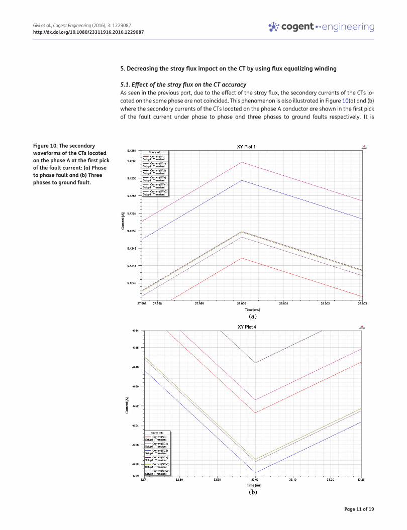
5.1. Effect of the stray flux on the CT accuracyAs seen in the previous part, due to the effect of the stray flux, the secondary currents of the CTs lo-cated on the same phase are not coincided. This phenomenon is also illustrated in Figure 10(a) and (b) where the secondary currents of the CTs located on the phase A conductor are shown in the first pick of the fault current under phase to phase and three phases to ground faults respectively. It is
Figure 10. The secondary waveforms of the CTs located on the phase A at the first pick of the fault current: (a) Phase to phase fault and (b) Three phases to ground fault.

Page 12 of 19
Givi et al., Cogent Engineering (2016), 3: 1229087http://dx.doi.org/10.1080/23311916.2016.1229087
observed that the difference between the secondary currents of the CTs feeding the generator dif-ferential relay may lead to the undesirable operation of this relay.
5.2. Using flux equalizing winding for the CTFigure 11 illustrates two possible configurations for the flux equalizing winding (Gajic, Hoist, Bonmann, & Baars, 2008). This winding always has an even number of segments. In Figure 11, it consists of four segments which have the same number of turns and are uniformly distributed around the CT core.
In the first topology shown in Figure 11(a), each two segments located on diametrically opposite sides of the core (1 and 3 or 2 and 4) are cross connected so as to prepare a path for the circulating current. This current counteracts the effect of its source namely the stray flux according to the Lenz law. Under normal operation, namely when there is no stray flux, no current flows in the winding.
In the second configuration as illustrated in Figure 11(b), all the segments are connected in paral-lel and they prepare the path for the circulating current. During the stray flux existence, this current generates a magnetic field which is opposed to the magnetic field of the stray flux. So the effect of the stray flux is diminished.
Figure 11. Two possible configurations for the flux equalizing winding.

Page 13 of 19
Givi et al., Cogent Engineering (2016), 3: 1229087http://dx.doi.org/10.1080/23311916.2016.1229087
In this paper, the first configuration is utilized for the CTs. The turn number of each segment of the flux equalizing winding is equal to 10. By increasing the turn number, the stray flux effect could be more decreased but this is in the expense of increasing the CT cost and weight. The modified CT with flux equalizing winding is depicted in Figure 12 where the violet parts are the four segments of the flux equalizing winding.
Under fault conditions, the stray flux originated from the adjacent phases decreases the CT ac-curacy. In this part, the effectiveness of the flux equalizing windings is evaluated for different types of the fault currents. For the single phase fault namely A→G fault as depicted in Figure 13, only the phase A of the conductors is excited by the corresponding fault current in the finite element soft-ware, namely no currents flow in the conductors of the phases B and C. It is obvious that under this
Figure 12. CT with flux equalizing winding.
Figure 13. Exciting the phase A primary conductor with the phase A current during the A→G fault.
0.00 20.00 40.00 60.00 80.00 100.00
Time [ms]
-60000.00
-40000.00
-20000.00
0.00
20000.00
40000.00
60000.00
80000.00
Cur
rent
[A]
XY Plot 1 ANSOFT
Curve InfoInputCurrent(AH)
Setup1 : TransientInputCurrent(AV)
Setup1 : TransientInputCurrent(BH)
Setup1 : TransientInputCurrent(BV)
Setup1 : TransientInputCurrent(CH)
Setup1 : TransientInputCurrent(CV)
Setup1 : Transient

Page 14 of 19
Givi et al., Cogent Engineering (2016), 3: 1229087http://dx.doi.org/10.1080/23311916.2016.1229087
Figure 14. Secondary currents of the two CTs of the Phase B that feed the differential relay during the phase A excitation with its current for A→G fault: (a) Without flux equalizing winding and (b) With flux equalizing winding.

Page 15 of 19
Givi et al., Cogent Engineering (2016), 3: 1229087http://dx.doi.org/10.1080/23311916.2016.1229087
Figure 15. Secondary currents of the two CTs of the Phase C that feed the differential relay during the phase A excitation with its current for A→G fault: (a) Without flux equalizing winding and (b) With flux equalizing winding.

Page 16 of 19
Givi et al., Cogent Engineering (2016), 3: 1229087http://dx.doi.org/10.1080/23311916.2016.1229087
condition, the currents induced in the CTs of the phases B and C are just due to the stray flux origi-nated from the phase A current. Then the induced currents in the CTs of the phases B and C are ex-tracted for two statues: first when these CTs are without flux equalizing winding and second when they are prepared with this winding. The results are presented in Figure 14(a) and (b); Figure 15(a) and (b). For two phases fault (like AB fault), the primary conductors of the phases A and B are excited with their corresponding currents as illustrated in Figure 16. Namely, no current flows in the phase C pri-mary conductor. Under these circumstances, the currents induced in the CTs located on the Phase C conductors are only due to the stray flux originated from the phases A and B currents. The current waveforms of these CTs are also presented for two conditions: when these CTs are without flux equalizing winding and when they are prepared with this winding. The results are given in the Figure 17(a) and (b). For more clarity, only the waveforms of the secondary currents of the CTs feeding the generator differential relay are shown.
The differential relay responses to the differential current of the CTs feeding it, namely, if the difference between the currents of the CTs feeding this relay exceeds the relay set point, it will operate. As summarized in Table 7, the maximum differential current between the two CTs feed-ing the differential relay is decreased considerably due to the flux equalizing winding utilization.
Figure 16. Exciting the phases A and B primary conductors with their currents during the AB fault.
0.00 20.00 40.00 60.00 80.00 100.00
Time [ms]
-80000.00
-60000.00
-40000.00
-20000.00
0.00
20000.00
40000.00
60000.00
80000.00
Cur
rent
[A
]
XY Plot 2 ANSOFT
Curve Info
InputCurrent(A)Setup1 : Transient
InputCurrent(B)Setup1 : Transient
InputCurrent(C)Setup1 : Transient

Page 17 of 19
Givi et al., Cogent Engineering (2016), 3: 1229087http://dx.doi.org/10.1080/23311916.2016.1229087
Table 7. Decreasing the negative impact of the stray flux on the CT using the flux equalizing windingFault type Percentage of decrease in
the maximum secondary current difference between
the CTs of the phase B
Percentage of decrease in the maximum secondary current difference between the CTs of
the phase CA→G 91.67 97.47
AB – 98.71
AB→G – 98.67
Figure 17. Secondary currents of the two CTs of the Phase C that feed the differential relay during the phases A and B excitation with their currents for AB fault: (a) Without flux equalizing winding and (b) With flux equalizing winding.
(a)
(b)
0.00 20.00 40.00 60.00 80.00 100.00
Time [ms]
-0.00010
-0.00005
0.00000
0.00005
0.00010
0.00015
0.00020
0.00025
Cur
rent
[A
]
XY Plot 4 ANSOFT
Curve Info
Current(SC2)Setup1 : Transient
Current(SCV1)Setup1 : Transient
0.00 20.00 40.00 60.00 80.00 100.00
Time [ms]
-3.00E-006
-2.50E-006
-2.00E-006
-1.50E-006
-1.00E-006
-5.00E-007
0.00E+000
5.00E-007
1.00E-006
Cur
rent
[A
]
XY Plot 4 ANSOFT
Curve Info
Current(SC2)Setup1 : Transient
Current(SCV1)Setup1 : Transient

Page 18 of 19
Givi et al., Cogent Engineering (2016), 3: 1229087http://dx.doi.org/10.1080/23311916.2016.1229087
6. DiscussionThe accuracy of output signal of the CTs utilized for differential protection may be affected by two main factors: saturation of the core and stray flux. In case of CT saturation, discrimination between internal fault currents and magnetizing inrush currents becomes difficult. On the other hand, stray flux deviates the output of the CTs from the correct waveform. Hence, the differential relay may consider this case as an internal fault and trip the breaker. The results in Section 5.1 prove that the difference between the currents of the CTs installed on the same phase of the generator may exceed the differential relay set point due to the stray flux impact. This results in the malfunction of this relay and disconnection of the generator from the power grid. To avoid this problem, one effective solution is to employ flux equalizing windings on the CT secondary to counteract the impact of the stray flux. The results presented in Section 5.2 confirm that this winding increases the CT accuracy in different fault conditions and thus improves the reliability of the differential protection scheme.
7. ConclusionThis paper is focused on modeling a typical power plant bus bar using FEM and analyzing the perfor-mance of protective current transformers installed on the conductors under fault conditions. The results confirm that during fault condition, the secondary currents of the CTs feeding the generator differential relays deviate from the correct waveforms due to the stray flux effect. This may lead to undesirable operation of this relay. In other words, the relay trips the breaker while no fault has oc-curred. To tackle this challenge, application of flux equalizing windings on the CT secondary is pro-posed to mitigate the stray flux impact. The results confirm the considerable effectiveness of this winding for reducing the negative impact of the stray flux during different fault conditions.
AcknowledgmentsThe authors wish to express their gratitude to MAPNA generator engineering and manufacturing company, PARS for presenting the required data for analysis.
FundingThe authors received no direct funding for this research.
Author detailsHadi Givi1
E-mail: [email protected] ID: http://orcid.org/0000-0001-6386-1455Javad Shokrollahi Moghani1
E-mail: [email protected] ID: http://orcid.org/0000-0001-9066-0667Haidar Samet2
E-mail: [email protected] ID: http://orcid.org/0000-0003-1367-38721 Department of Electrical Engineering, Amirkabir University of
Technology, Tehran, Iran.2 School of Electrical and Computer Engineering, Shiraz
University, Shiraz, Iran.
Citation informationCite this article as: Mitigating the negative impact of the stray flux on the current transformers using flux equalizing windings, Hadi Givi, Javad Shokrollahi Moghani & Haidar Samet, Cogent Engineering (2016), 3: 1229087.
ReferencesBraun, A. (1977). Determination of current transformer errors
at primary currents up to 100,000 A. IEEE Transactions on Instrumentation and Measurement, 26, 263–267. doi:10.1109/tim.1977.4314550
Chothani, N. G., & Bhalja, B. R. (2014). New algorithm for current transformer saturation detection and compensation based on derivatives of secondary currents and Newton’s backward difference formulae. IET Generation, Transmission & Distribution, 8, 841–850. doi:10.1049/iet-gtd.2013.0324
Erenturk, K. (2009). ANFIS-based compensation algorithm for current-transformer saturation effects. IEEE Transactions Power Delivery, 24, 195–201. doi:10.1109/tpwrd.2008.2005882
Esmail, E. M., Elkalashy, N. I., Kawady, T. A., Taalab, A.-M. I., & Lehtonen, M. (2015). Detection of partial saturation and waveform compensation of current transformers. IEEE Transactions Power Delivery, 30, 1620–1622. doi:10.1109/tpwrd.2014.2361032
Gajic, Z., Hoist, S., Bonmann, D., & Baars, D. A. W. (2008). Influence of stray flux on protection systems. IET 9th International Conference on Developments in Power Systems Protection (DPSP 2008). doi:10.1049/cp:20080075
Haiyu, Yu, Yuan, Jiansheng, & Zou, Jun (2006). Design of novel structure current transformer with shielding coils for overcoming the saturation of core. IEEE Transactions on Magnetics, 42, 1431–1434. doi:10.1109/tmag.2006.872478
Hajipour, E., Vakilian, M., & Sanaye-Pasand, M. (2015). Current-transformer saturation compensation for transformer differential relays. IEEE Transactions Power Delivery, 30, 2293–2302. doi:10.1109/tpwrd.2015.2411736
Hajipour, E., Salehizadeh, M., Vakilian, M., & Sanaye-Pasand, M. (2016). Residual flux mitigation of protective current transformers used in an autoreclosing scheme. IEEE Transactions Power Delivery, 31, 1636–1644. doi:10.1109/tpwrd.2015.2480773
Hooshyar, A., & Sanaye-Pasand, M. (2015). Waveshape recognition technique to detect current transformer saturation. IET Generation, Transmission & Distribution, 9, 1430–1438. doi:10.1049/iet-gtd.2014.1147
Khorashadi-Zadeh, H., & Sanaye-Pasand, M. (2006). Correction of Saturated current transformers secondary current using ANNs. IEEE Transactions Power Delivery, 21, 73–79. doi:10.1109/tpwrd.2005.858799
O’Kelly, D. (1992). Calculation of the transient performance of protective current transformers including core hysteresis. IEE Proceedings C Generation, Transmission and Distribution, 139, 455–460. doi:10.1049/ip-c.1992.0063

Page 19 of 19
Givi et al., Cogent Engineering (2016), 3: 1229087http://dx.doi.org/10.1080/23311916.2016.1229087
© 2016 The Author(s). This open access article is distributed under a Creative Commons Attribution (CC-BY) 4.0 license.You are free to: Share — copy and redistribute the material in any medium or format Adapt — remix, transform, and build upon the material for any purpose, even commercially.The licensor cannot revoke these freedoms as long as you follow the license terms.
Under the following terms:Attribution — You must give appropriate credit, provide a link to the license, and indicate if changes were made. You may do so in any reasonable manner, but not in any way that suggests the licensor endorses you or your use. No additional restrictions You may not apply legal terms or technological measures that legally restrict others from doing anything the license permits.
Cogent Engineering (ISSN: 2331-1916) is published by Cogent OA, part of Taylor & Francis Group. Publishing with Cogent OA ensures:• Immediate, universal access to your article on publication• High visibility and discoverability via the Cogent OA website as well as Taylor & Francis Online• Download and citation statistics for your article• Rapid online publication• Input from, and dialog with, expert editors and editorial boards• Retention of full copyright of your article• Guaranteed legacy preservation of your article• Discounts and waivers for authors in developing regionsSubmit your manuscript to a Cogent OA journal at www.CogentOA.com
Ozgonenel, O. (2013). Correction of saturated current from measurement current transformer. IET Electric Power Applications, 7, 580–585. doi:10.1049/iet-epa.2013.0105
Pfuntner, R. A. (1951). The accuracy of current transformers adjacent to heavy current buses. AIEE Transactions, 70, 1656–1661.
Qu, K., Zhao, W., Yang, P., Huang, S., & Jiang, B. (2009). Interference mechanism of external current on heavy current transformer. 2009 IEEE Instrumentation and Measurement Technology Conference. doi:10.1109/imtc.2009.5168647
Rebizant, W., & Bejmert, D. (2007). Current-transformer saturation detection with genetically optimized neural networks. IEEE Transactions Power Delivery, 22, 820–827. doi:10.1109/tpwrd.2007.893363
Rezaei-Zare, A., Iravani, R., Sanaye-Pasand, M., Mohseni, H., & Farhangi, S. (2008). An accurate current transformer model based on Preisach theory for the analysis of electromagnetic transients. IEEE Transactions Power Delivery, 23, 233–242. doi:10.1109/tpwrd.2007.905416
Schettino, B. M., Duque, C. A., Silveira, P. M., Ribeiro, P. F., & Cerqueira, A. S. (2014). A new method of current-
transformer saturation detection in the presence of noise. IEEE Transactions Power Delivery, 29, 1760–1767. doi:10.1109/tpwrd.2013.2294079
Schettino, B. M., Duque, C. A., & Silveira, P. M. (2016). Current-transformer saturation detection using Savitzky–Golay filter. IEEE Transactions Power Delivery, 31, 1400–1401. doi:10.1109/tpwrd.2016.2521327
Seely, S. (1970). Effect of stray flux on current transformers. Journal of Science & Technology, 37, 115–120.
Stanbury, M., & Djekic, Z. (2015). The Impact of current-transformer saturation on transformer differential protection. IEEE Transactions Power Delivery, 30, 1278–1287. doi:10.1109/tpwrd.2014.2372794
Telino Meneses, L., & Laurindo Maitelli, A. (2016). A proposal for improving the current transformers accuracy. IEEE Latin America Transactions, 14, 430–436. doi:10.1109/tla.2016.7437176
Wiszniewski, A., Rebizant, W., & Schiel, L. (2008). Correction of current transformer transient performance. IEEE Transactions Power Delivery, 23, 624–632. doi:10.1109/tpwrd.2008.915832