mit 6.035 conversion to low level intermediate representation unstructured flow of control and...
TRANSCRIPT
MIT 6.035Conversion to Low Level
Intermediate Representation
Unstructured Flow of Control and Instruction Flattening
Martin Rinard
Laboratory for Computer Science
Massachusetts Institute of Technology

GoalRemain Largely Machine
Independent
ButMove Closer to Standard Machine
Model (flat address space, branches)
Control Flow Graph (CFG)
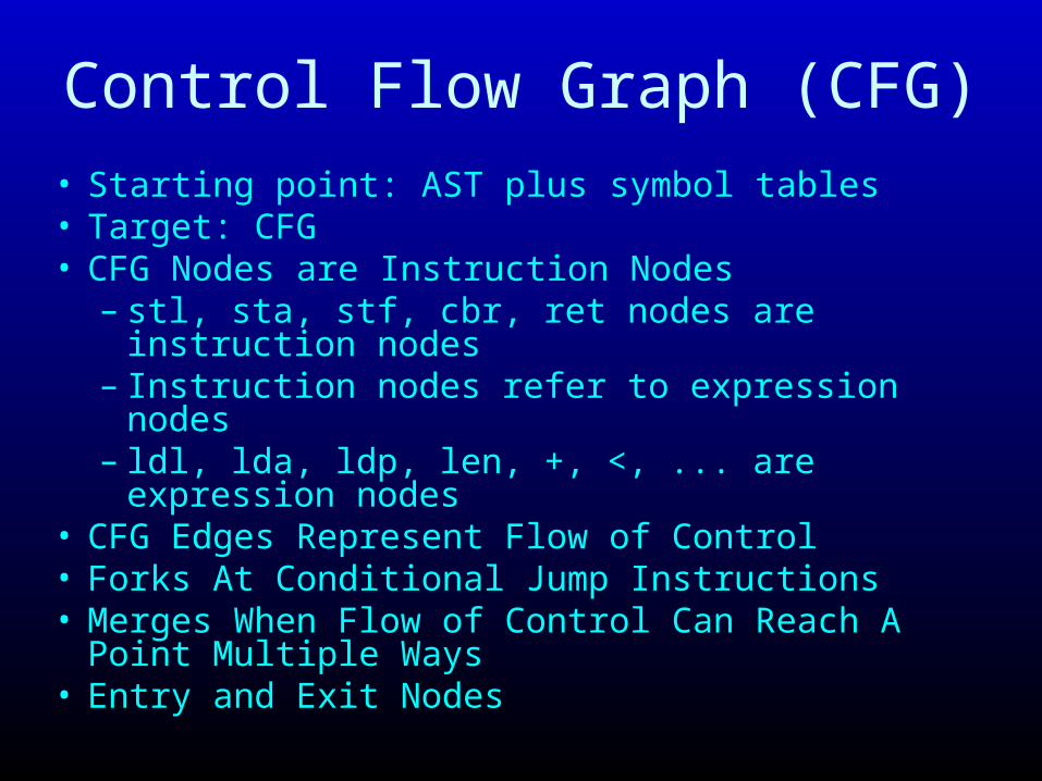
• Starting point: AST plus symbol tables• Target: CFG• CFG Nodes are Instruction Nodes
– stl, sta, stf, cbr, ret nodes are instruction nodes– Instruction nodes refer to expression nodes– ldl, lda, ldp, len, +, <, ... are expression nodes
• CFG Edges Represent Flow of Control• Forks At Conditional Jump Instructions• Merges When Flow of Control Can Reach A Point
Multiple Ways• Entry and Exit Nodes

ldl i
<
len
lda
+
ldp x
ldl i
sta
ldl i
ldf v
ldf v
ldf v
cbr
entry
exit
while (i < v.length)v[i] = v[i]+x;
Control FlowEdges
Instruction andExpression Edges
Pattern for while loop
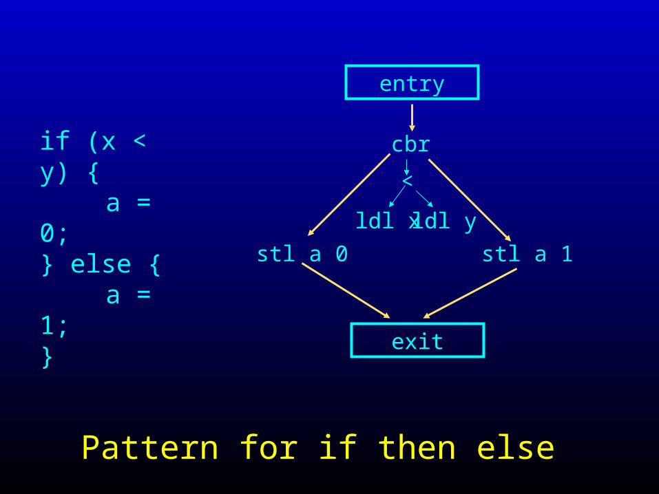
if (x < y) { a = 0;
} else { a = 1;
}
entry
ldl x ldl y
<
cbr
stl a 0 stl a 1
exit
Pattern for if then else

Short-Circuit Conditionals
• In program, conditionals have a condition written as a boolean expression((i < v.len) && (v[i] != 0)) || i > k)
• Semantics say should execute only as much as required to determine condition– Evaluate (v[i] != 0) only if (i < v.len) is true– Evaluate i > k only if ((i < v.len) && (v[i] != 0)) is
false
• Use control-flow graph to represent this short-circuit evaluation

Short-Circuit Conditionalswhile (i < v.length && v[i] != 0) {
i = i+1;}
entry
ldl i len
<
cbr
stl iexit
ldf v
lda 0
!=
cbr
ldf v ldl ildl i 1
+
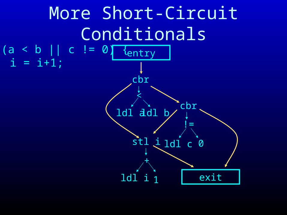
More Short-Circuit Conditionalsif (a < b || c != 0) {
i = i+1;}
entry
ldl a
<
cbr
stl i
exit
cbr
ldl i 1
+
ldl b
ldl c 0
!=

Routines for Destructuring Program Representation
destruct(n)
generates lowered form of structured code represented by n
returns (b,e) - b is begin node, e is end node in destructed form
shortcircuit(c, t, f)
generates short-circuit form of conditional represented by c
if c is true, control flows to t node
if c is false, control flows to f node
returns b - b is begin node for condition evaluation
new kind of node - nop node

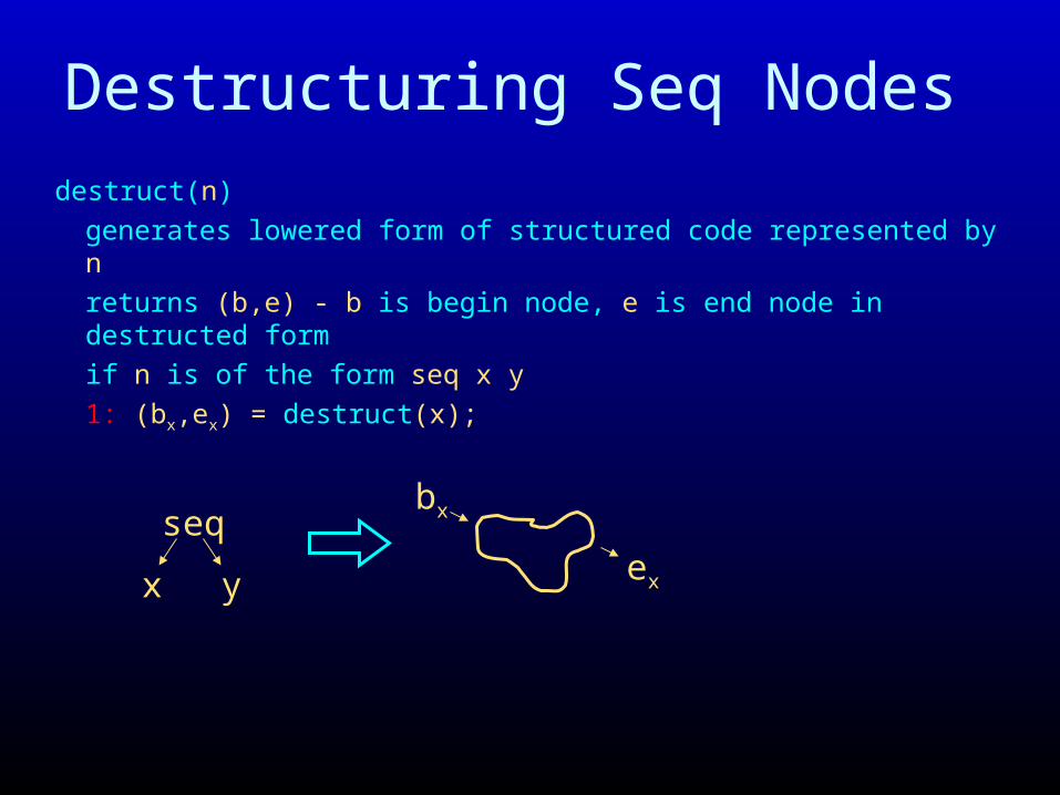
Destructuring Seq Nodes
destruct(n)
generates lowered form of structured code represented by n
returns (b,e) - b is begin node, e is end node in destructed form
if n is of the form seq x y
1: (bx,ex) = destruct(x); 2: (by,ey) = destruct(y);
3: next(ex) = by; 4: return (bx, ey);
seq
x y
bx
ex by
ey
Destructuring Seq Nodes
destruct(n)
generates lowered form of structured code represented by n
returns (b,e) - b is begin node, e is end node in destructed form
if n is of the form seq x y
1: (bx,ex) = destruct(x);
seq
x y
bx
ex

Destructuring Seq Nodes
destruct(n)
generates lowered form of structured code represented by n
returns (b,e) - b is begin node, e is end node in destructed form
if n is of the form seq x y
1: (bx,ex) = destruct(x); 2: (by,ey) = destruct(y);
seq
x y
bx
ex by
ey

Destructuring Seq Nodes
destruct(n)
generates lowered form of structured code represented by n
returns (b,e) - b is begin node, e is end node in destructed form
if n is of the form seq x y
1: (bx,ex) = destruct(x); 2: (by,ey) = destruct(y);
3: next(ex) = by;
seq
x y
bx
ex by
ey

Destructuring Seq Nodes
destruct(n)
generates lowered form of structured code represented by n
returns (b,e) - b is begin node, e is end node in destructed form
if n is of the form seq x y
1: (bx,ex) = destruct(x); 2: (by,ey) = destruct(y);
3: next(ex) = by; 4: return (bx, ey);
seq
x y
bx
ex by
ey

Destructuring If Nodes destruct(n)
generates lowered form of structured code represented by n
returns (b,e) - b is begin node, e is end node in destructed form
if n is of the form if c x y
1: (bx,ex) = destruct(x); 2: (by,ey) = destruct(y);
3: e = new nop; 4: next(ex) = e; 5: next(ey) = e;
6: bc = shortcircuit(c, bx, by); 7: return (bc, e);
if
c ybc
bx ex
ex by ey

Destructuring If Nodes destruct(n)
generates lowered form of structured code represented by n
returns (b,e) - b is begin node, e is end node in destructed form
if n is of the form if c x y
1: (bx,ex) = destruct(x);
if
c y
bx ex
x

Destructuring If Nodes destruct(n)
generates lowered form of structured code represented by n
returns (b,e) - b is begin node, e is end node in destructed form
if n is of the form if c x y
1: (bx,ex) = destruct(x); 2: (by,ey) = destruct(y);
if
c y
bx ex
x by ey

Destructuring If Nodes destruct(n)
generates lowered form of structured code represented by n
returns (b,e) - b is begin node, e is end node in destructed form
if n is of the form if c x y
1: (bx,ex) = destruct(x); 2: (by,ey) = destruct(y);
3: e = new nop;
if
c y
bx ex
ex by ey

Destructuring If Nodes destruct(n)
generates lowered form of structured code represented by n
returns (b,e) - b is begin node, e is end node in destructed form
if n is of the form if c x y
1: (bx,ex) = destruct(x); 2: (by,ey) = destruct(y);
3: e = new nop; 4: next(ex) = e; 5: next(ey) = e;
6: bc = shortcircuit(c, bx, by);
if
c ybc
bx ex
ex by ey

Destructuring If Nodes destruct(n)
generates lowered form of structured code represented by n
returns (b,e) - b is begin node, e is end node in destructed form
if n is of the form if c x y
1: (bx,ex) = destruct(x); 2: (by,ey) = destruct(y);
3: e = new nop; 4: next(ex) = e; 5: next(ey) = e;
6: bc = shortcircuit(c, bx, by); 7: return (bc, e);
if
c ybc
bx ex
ex by ey

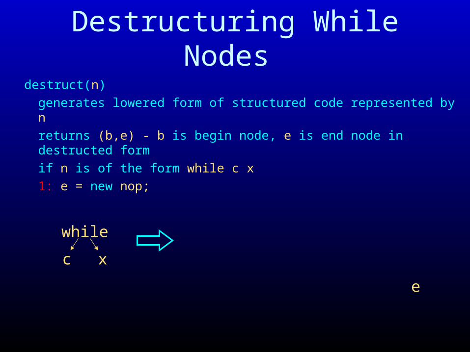
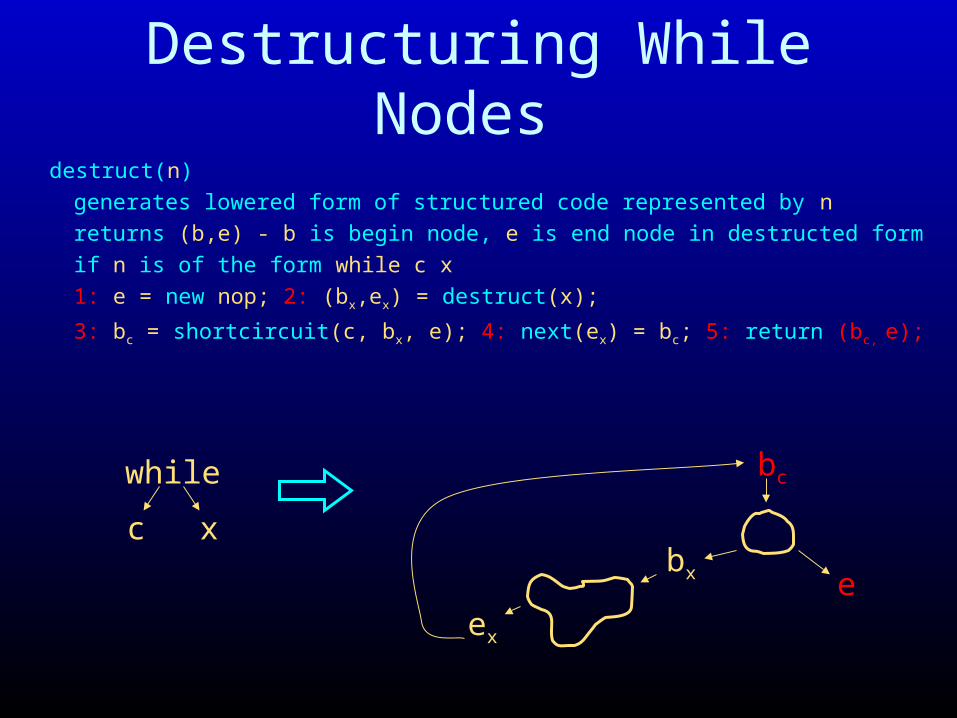
Destructuring While Nodes
destruct(n)
generates lowered form of structured code represented by n
returns (b,e) - b is begin node, e is end node in destructed form
if n is of the form while c x
1: e = new nop; 2: (bx,ex) = destruct(x);
3: bc = shortcircuit(c, bx, e); 4: next(ex) = bc; 5: return (bc, e);
while
c x
bc
ebx
ex
Destructuring While Nodes
destruct(n)
generates lowered form of structured code represented by n
returns (b,e) - b is begin node, e is end node in destructed form
if n is of the form while c x
1: e = new nop;
while
c x
e

Destructuring While Nodes
destruct(n)
generates lowered form of structured code represented by n
returns (b,e) - b is begin node, e is end node in destructed form
if n is of the form while c x
1: e = new nop; 2: (bx,ex) = destruct(x);
while
c x
ebx
ex

Destructuring While Nodes
destruct(n)
generates lowered form of structured code represented by n
returns (b,e) - b is begin node, e is end node in destructed form
if n is of the form while c x
1: e = new nop; 2: (bx,ex) = destruct(x);
3: bc = shortcircuit(c, bx, e);
while
c x
bc
ebx
ex

Destructuring While Nodes
destruct(n)
generates lowered form of structured code represented by n
returns (b,e) - b is begin node, e is end node in destructed form
if n is of the form while c x
1: e = new nop; 2: (bx,ex) = destruct(x);
3: bc = shortcircuit(c, bx, e); 4: next(ex) = bc;
while
c x
bc
ebx
ex
Destructuring While Nodes
destruct(n)
generates lowered form of structured code represented by n
returns (b,e) - b is begin node, e is end node in destructed form
if n is of the form while c x
1: e = new nop; 2: (bx,ex) = destruct(x);
3: bc = shortcircuit(c, bx, e); 4: next(ex) = bc; 5: return (bc, e);
while
c x
bc
ebx
ex

Shortcircuiting And Conditions
shortcircuit(c, t, f)
generates shortcircuit form of conditional represented by c
returns b - b is begin node of shortcircuit form
if c is of the form c1 && c2
1: b2 = shortcircuit(c2, t, f); 2: b1 = shortcircuit(c1, b2, f);
3: return (b1);
c1 && c2
b1
fb2
t

Shortcircuiting And Conditions
shortcircuit(c, t, f)
generates shortcircuit form of conditional represented by c
returns b - b is begin node of shortcircuit form
if c is of the form c1 && c2
1: b2 = shortcircuit(c2, t, f);
c1 && c2
fb2
t

Shortcircuiting And Conditions
shortcircuit(c, t, f)
generates shortcircuit form of conditional represented by c
returns b - b is begin node of shortcircuit form
if c is of the form c1 && c2
1: b2 = shortcircuit(c2, t, f); 2: b1 = shortcircuit(c1, b2, f);
c1 && c2
b1
fb2
t

Shortcircuiting And Conditions
shortcircuit(c, t, f)
generates shortcircuit form of conditional represented by c
returns b - b is begin node of shortcircuit form
if c is of the form c1 && c2
1: b2 = shortcircuit(c2, t, f); 2: b1 = shortcircuit(c1, b2, f);
3: return (b1);
c1 && c2
b1
fb2
t
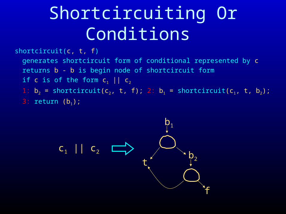
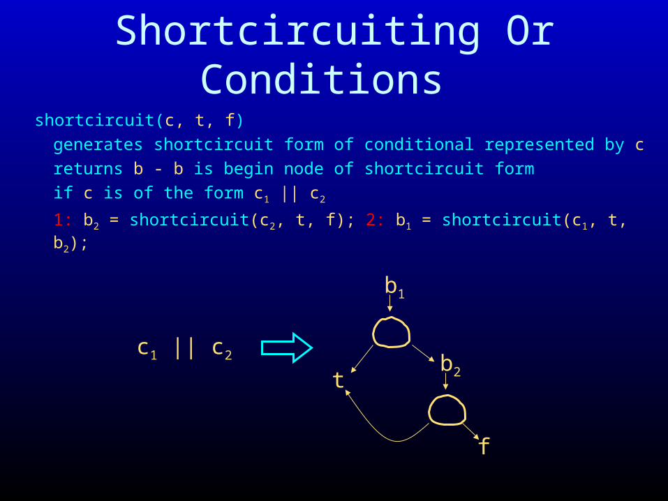
Shortcircuiting Or Conditions
shortcircuit(c, t, f)
generates shortcircuit form of conditional represented by c
returns b - b is begin node of shortcircuit form
if c is of the form c1 || c2
1: b2 = shortcircuit(c2, t, f); 2: b1 = shortcircuit(c1, t, b2);
3: return (b1);
c1 || c2
b1
f
b2t

Shortcircuiting Or Conditions
shortcircuit(c, t, f)
generates shortcircuit form of conditional represented by c
returns b - b is begin node of shortcircuit form
if c is of the form c1 || c2
1: b2 = shortcircuit(c2, t, f);
c1 || c2
f
b2t
Shortcircuiting Or Conditions
shortcircuit(c, t, f)
generates shortcircuit form of conditional represented by c
returns b - b is begin node of shortcircuit form
if c is of the form c1 || c2
1: b2 = shortcircuit(c2, t, f); 2: b1 = shortcircuit(c1, t, b2);
c1 || c2
b1
f
b2t

Shortcircuiting Or Conditions
shortcircuit(c, t, f)
generates shortcircuit form of conditional represented by c
returns b - b is begin node of shortcircuit form
if c is of the form c1 || c2
1: b2 = shortcircuit(c2, t, f); 2: b1 = shortcircuit(c1, t, b2);
3: return (b1);
c1 || c2
b1
f
b2t
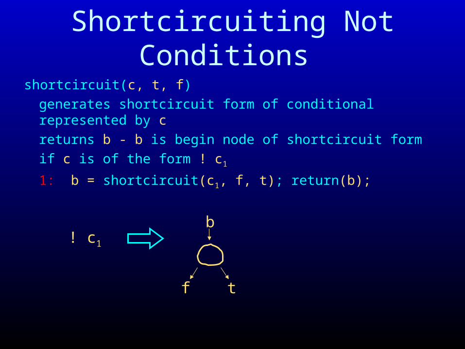
Shortcircuiting Not Conditions
shortcircuit(c, t, f)
generates shortcircuit form of conditional represented by c
returns b - b is begin node of shortcircuit form
if c is of the form ! c1
1: b = shortcircuit(c1, f, t); return(b);
b
f t
! c1

Computed Conditions
shortcircuit(c, t, f)
generates shortcircuit form of conditional represented by c
returns b - b is begin node of shortcircuit form
if c is of the form e1 < e2
1: b = new cbr(e1 < e2, t, f); 2: return (b);
e1 < e2
e1 e2
<
cbr
t f
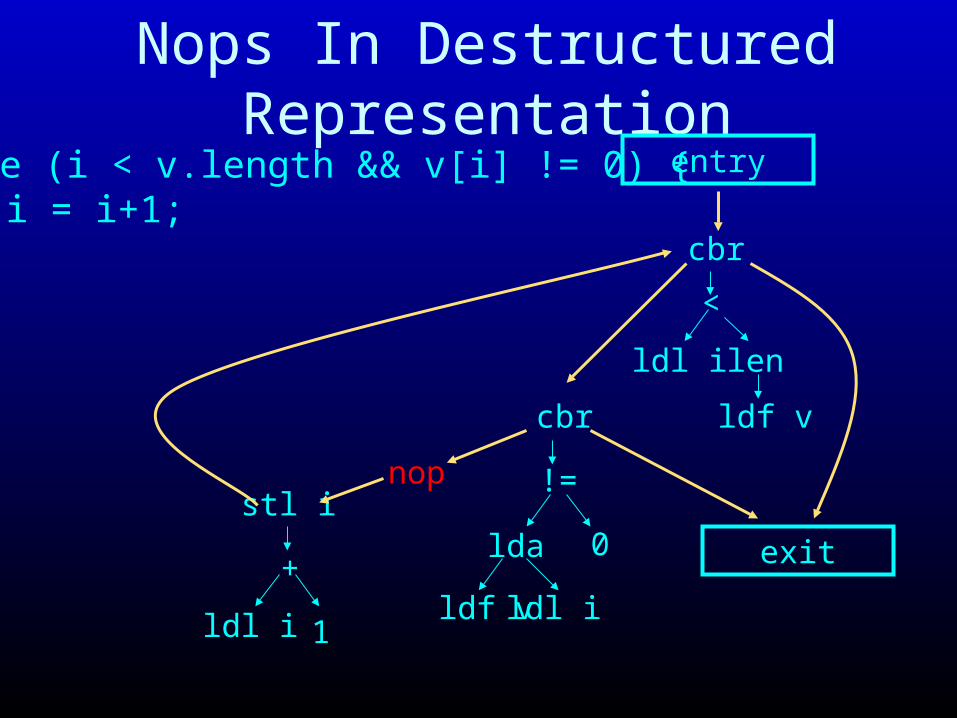
Nops In Destructured Representationwhile (i < v.length && v[i] != 0) {
i = i+1;}
entry
ldl i len
<
cbr
stl i
exit
ldf v
lda 0
!=
cbr
ldf v ldl ildl i 1
+
nop

Eliminating Nops Via Peephole Optimization
nop
... ...

Flattening Expression Trees
• Start with expression tree (- (+ (ldl i) (ldl j)) 1)• Produce flat sequence of
three-address instructions– ldl t1, i
– ldl t2, j
– add t3, t1, t2
– sub t4, t3, 1
• Facilitates translation to machine code• Facilitates optimizations and transformations• Key concept: compiler-generated temps
ldl i
+
ldl j
-
1

Handling Temps
• Each procedure has its own set of temps
• Make a temp table for the procedure
• Store information about temps in temp table

Three-Address Instructions– ldl temp, local
– ldp temp, parameter
– ldf temp, field
– lda temp, tempArray, tempIndex
– len temp, tempArray
– stl temp, local
– stp parm, temp
– stf temp, field
– sta temp, tempArray, tempIndex
– add dst, src1, src2– sub dst, src1, src2– sll dst, src1, src2– slt dst, src1, src2
dst, src1, src2all temps(or constants)
All of these have a reference to the next
instruction to execute

Conditional Branch Instructions• Two conditional branch instructions
– breqz temp, (trueIns, falseIns)– brneqz temp, (trueIns, falseIns)
• Branches have two instruction references– Next instruction if branch taken– Next instruction if branch not taken
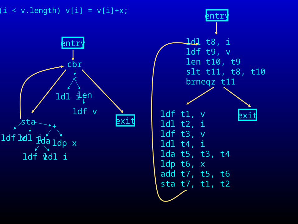
while (i < v.length) v[i] = v[i]+x;
ldl i
<
len
lda
+
ldp x
ldl i
sta
ldl i
ldf v
ldf v
ldf v
cbr
entry
exitldf t1, vldl t2, ildf t3, vldl t4, ilda t5, t3, t4ldp t6, xadd t7, t5, t6sta t7, t1, t2
ldl t8, ildf t9, vlen t10, t9slt t11, t8, t10 brneqz t11
entry
exit
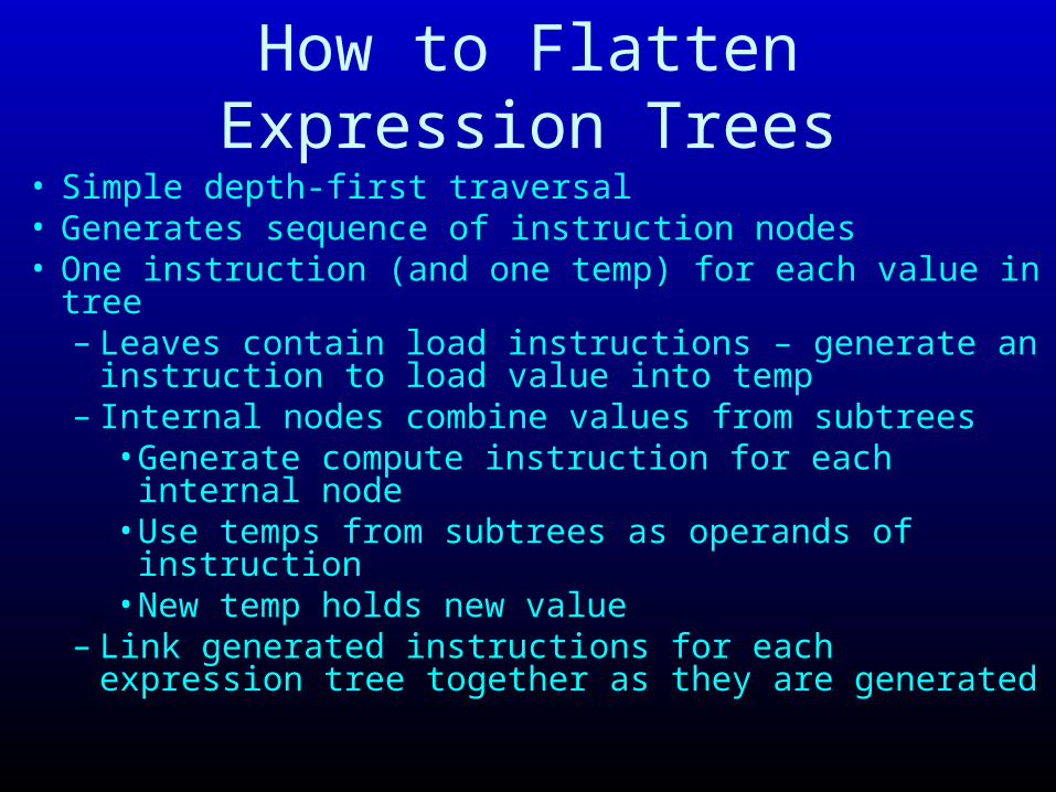
How to Flatten Expression Trees
• Simple depth-first traversal• Generates sequence of instruction nodes• One instruction (and one temp) for each value in tree
– Leaves contain load instructions – generate an instruction to load value into temp
– Internal nodes combine values from subtrees• Generate compute instruction for each internal node• Use temps from subtrees as operands of instruction• New temp holds new value
– Link generated instructions for each expression tree together as they are generated

while (i < v.length) v[i] = v[i]+x;
ldl i
<
len
lda
+
ldp x
ldl i
sta
ldl i
ldf v
ldf v
ldf v
cbr
entry
exitldf t1, v
ldl t2, i
ldf t3, vldl t4, ilda t5, t3, t4ldp t6, xadd t7, t5, t
ldl t8, Ildf t9, vlen t10, t9slt t11, t8, t10

How to Flatten Instructions
• Leverage expression tree flattening• Store instructions
– Flatten expression trees for operands of store – Generate a store instruction that uses temps from
flattened expression subtrees• Branch instructions
– Flatten condition expression– Generate a conditional branch instruction that uses
temp from flattened condition expression• Link generated instructions for each instruction
together as they are generated

while (i < v.length) v[i] = v[i]+x;
ldl i
<
len
lda
+
ldp x
ldl i
sta
ldl i
ldf v
ldf v
ldf v
cbr
entry
exitldf t1, v
ldl t2, I
ldf t3, vldl t4, ilda t5, t3, t4ldp t6, xadd t7, t5, t
ldl t8, Ildf t9, vlen t10, t9slt t11, t8, t10
sta t7, t1, t2

Reconnecting Control Flow Graph Edges
• Instruction correspondence map M– M(n) = (n1,n2)– n is a node in high-level IR– n1 is the first node in instruction sequence
resulting from the flattening of n– n2 is the last node in instruction sequence resulting
from flattening of n• M is used to reestablish control-flow links after
flattening• Typical implementation of M would be a hash table

while (i < v.length) v[i] = v[i]+x;
ldl i
<
len
lda
+
ldp x
ldl i
sta
ldl i
ldf v
ldf v
ldf v
cbr
entry
exitldf t1, vldl t2, ildf t3, vldl t4, ilda t5, t3, t4ldp t6, xadd t7, t5, t6sta t7, t1, t2
ldl t8, ildf t9, vlen t10, t9slt t11, t8, t10 brneqz t11
entry
exit
first
last
first
last

Using M to Reestablish Links• Traverse high-level IR
– Generate (low-level IR) instruction sequence for each store and branch instruction
– Record first and last generated instructions in M• Traverse high-level IR again
– Use M to link (low-level IR) instructions– For each link <n1,n2> in high-level IR
• Let (f1,l1) = M(n1) and (f2,l2) = M(n2)• Link l1 to f2 in low-level IR
• Why have M? Why not just use results of traversal?

while (i < v.length) v[i] = v[i]+x;
ldl i
<
len
lda
+
ldp x
ldl i
sta
ldl i
ldf v
ldf v
ldf v
cbr
entry
exitldf t1, vldl t2, ildf t3, vldl t4, ilda t5, t3, t4ldp t6, xadd t7, t5, t6sta t7, t1, t2
ldl t8, ildf t9, vlen t10, t9slt t11, t8, t10 brneqz t11
entry
exit
first
last
first
last
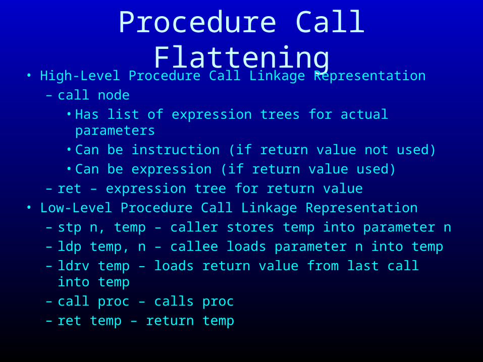
Procedure Call Flattening• High-Level Procedure Call Linkage Representation
– call node• Has list of expression trees for actual parameters• Can be instruction (if return value not used)• Can be expression (if return value used)
– ret – expression tree for return value• Low-Level Procedure Call Linkage Representation
– stp n, temp – caller stores temp into parameter n– ldp temp, n – callee loads parameter n into temp – ldrv temp – loads return value from last call into temp– call proc – calls proc– ret temp – return temp

Procedure Call Example
ldf t1, astp 0, t1call fldrv t2ldl t3, bstp 0, t3call gldrv t4add t5, t2, t3
call g
ldl b
call f
ldf a
+
f(a) + g(b)

Putting It All Together
• Generate while, if CFG patterns• Generate short-circuit conditional CFG• Flatten expression trees
– Traverse CFG to flatten each expression tree (temps hold intermediate and final values)
– Use results of expression tree flattening to produce sequence of nodes for each statement
– Store first and last node for each instruction in M– Use M to reconnect CFG edges
• Result is flattened IR

Summary
• Control-flow graph representation– Nodes represent computation– Edges represent flow of control
• Pattern-based approach for eliminating structured flow of control
• Short-circuit conditionals
• Flattening expression trees and instructions
MIT 6.035Conversion to Low Level
Intermediate Representation
Conversion to Flat Address SpaceGenerating Machine Code
Martin Rinard
Laboratory for Computer Science
Massachusetts Institute of Technology

Memory Model for Target Machine• Single flat memory
– composed of words– byte addressable
• Nodes Model Load and Store Instructions– ld temp, addr,offset - loads contents of memory at location
addr+offset into temp– li temp, num – puts num (a constant) into temp– st temp, addr, offset- stores value in temp to memory
location addr+offset– Will replace lda, ldf, ldl nodes with ld nodes– Will replace sta, stf, stl nodes with st nodes– Keep lpd, stp nodes
• Key concept: home for every value

Memory Layout
Stack
Generated Code
HeapObjects
Arrays
locals(parameters)
• When is generatedcode set up?
• When does stack grow and shrink?
• When does the heap grow and shrink?
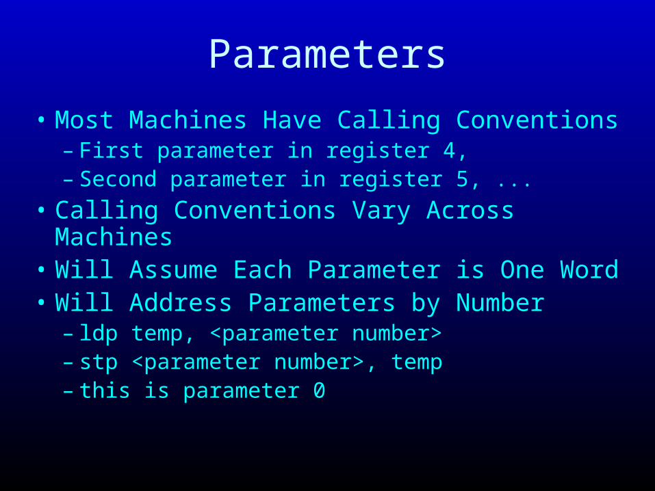
Parameters
• Most Machines Have Calling Conventions – First parameter in register 4,– Second parameter in register 5, ...
• Calling Conventions Vary Across Machines• Will Assume Each Parameter is One Word• Will Address Parameters by Number
– ldp temp, <parameter number>– stp <parameter number>, temp– this is parameter 0
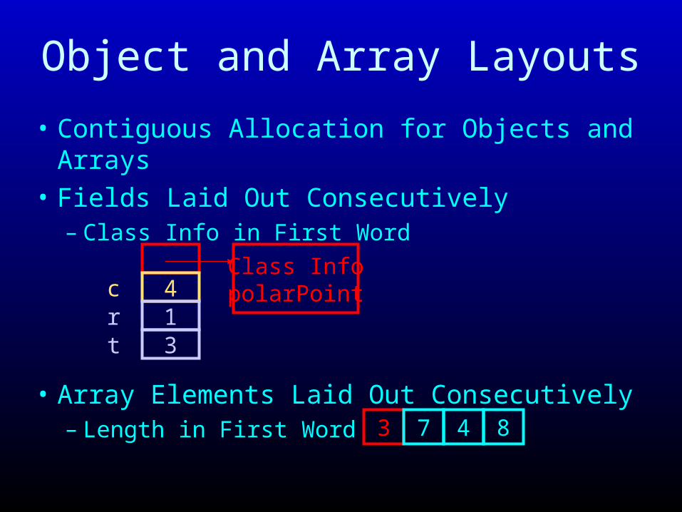
Object and Array Layouts
• Contiguous Allocation for Objects and Arrays
• Fields Laid Out Consecutively– Class Info in First Word
• Array Elements Laid Out Consecutively– Length in First Word 3 7 4 8
413
crt
Class InfopolarPoint

Accessing Fields
• Assume this points to start of object
• What is address of r field?– assume each field takes 4 bytes
• this+(2*4), or base+field offset
413
crt
this
Class InfopolarPoint

Converting ldf Nodes to ld Nodes
• Compute field offsets – traverse class hierarchy (field symbol tables)– offsets for subclass start where offsets for
superclass end– store offsets in field symbol tables
• Use offsets to replace ldf nodes with ld nodes

Cartesian Point Field Offsets
yx field descriptor for x (8)
field descriptor for y (12)
distance method descriptor for distance
c field descriptor for c (4)
getColor method descriptor for getColor
class descriptorfor point
class descriptorfor cartesianPoint
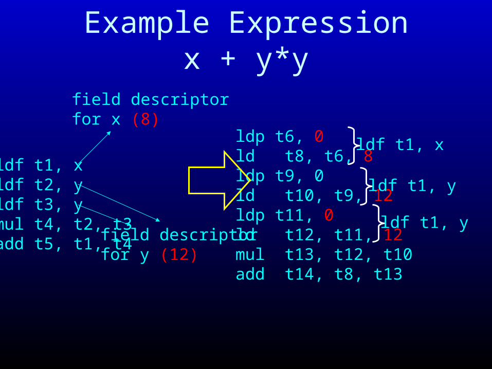
Example Expressionx + y*y
ldf t1, xldf t2, yldf t3, ymul t4, t2, t3add t5, t1, t4
field descriptor for x (8)
field descriptor for y (12)
ldp t6, 0ld t8, t6, 8ldp t9, 0ld t10, t9, 12ldp t11, 0ld t12, t11, 12mul t13, t12, t10add t14, t8, t13
ldf t1, x
ldf t1, y
ldf t1, y

Accessing Array Elements
• Assume array variable points to start of array
• Array elements stored contiguously
• Don’t forget length at front of array
• What is address of v[5]?
• Assume 4 byte integers
• (address in v) + 4 + (5*4)
• Array Base + 4 + (index * element size)

Converting lda Nodes to ld Nodes
• Compute Address of Array Element– Base + 4 + (index * element size)
• ld From that Address
• Offset of ld Node is 0
• Optimization– Put offset to skip length in ld instruction
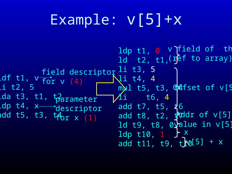
Example: v[5]+x
ldf t1, vli t2, 5lda t3, t1, t2ldp t4, xadd t5, t3, t4
field descriptor for v (4)
parameter descriptorfor x (1)
ldp t1, 0ld t2, t1, 4li t3, 5li t4, 4mul t5, t3, t4li t6, 4add t7, t5, t6add t8, t2, t7ld t9, t8, 0ldp t10, 1add t11, t9, t10
v field of this (ref to array)
Offset of v[5]
Addr of v[5]value in v[5]x
v[5] + x
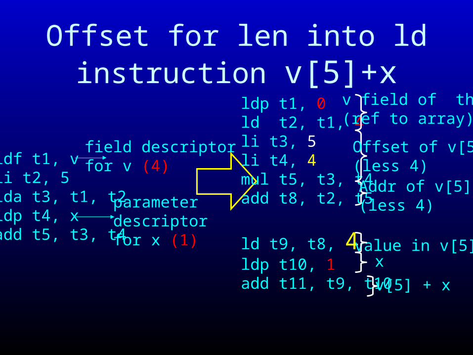
Offset for len into ld instruction v[5]+x
ldf t1, vli t2, 5lda t3, t1, t2ldp t4, xadd t5, t3, t4
field descriptor for v (4)
parameter descriptorfor x (1)
ldp t1, 0ld t2, t1, 4li t3, 5li t4, 4mul t5, t3, t4add t8, t2, t5
ld t9, t8, 4ldp t10, 1add t11, t9, t10
v field of this (ref to array)
Offset of v[5](less 4)Addr of v[5](less 4)
value in v[5]x
v[5] + x

Local Variables
• Assume are allocated on call stack
• Address using offsets from call stack pointer
• Remember, stack grows down, not up, so offsets are all positive
• Special symbol sp contains stack pointer
• Need some information about activation record format to compute offsets in call stack

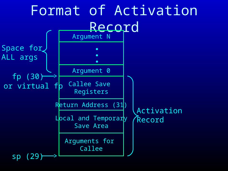
Format of Activation Record
Argument N
Argument 0
...
Return Address (31)
Callee Save Registers
Local and TemporarySave Area
Arguments for Callee
ActivationRecord
fp (30)
sp (29)
or virtual fp
Space forALL args

Actions On Method Invocation• Caller
– Save caller-save registers– Set up parameters using calling convention– Set up return address using calling convention– Jump to callee
• Callee– Allocate stack frame, set up frame pointer– Save return address, callee-save registers– Compute– Set up return value using calling convention– Deallocate stack frame, restore callee-save registers, – Return to caller
• Caller– Restore caller-save registers– Retrieve return value– Continue to compute
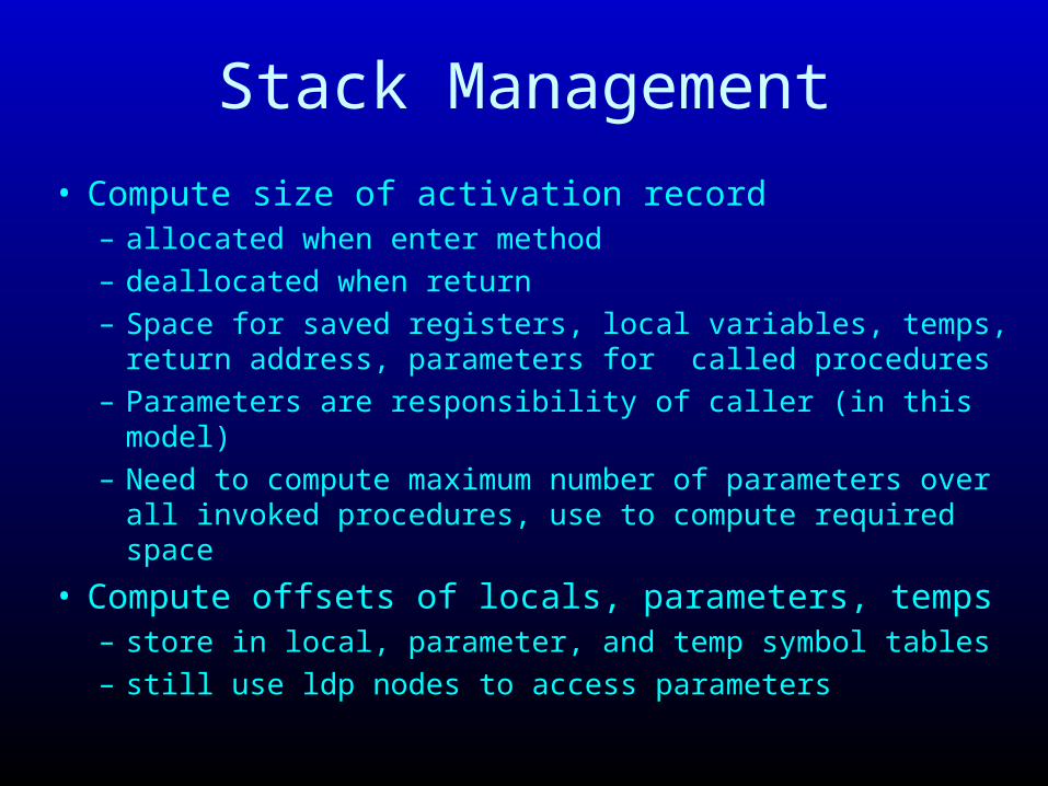
Stack Management
• Compute size of activation record– allocated when enter method
– deallocated when return
– Space for saved registers, local variables, temps, return address, parameters for called procedures
– Parameters are responsibility of caller (in this model)
– Need to compute maximum number of parameters over all invoked procedures, use to compute required space
• Compute offsets of locals, parameters, temps– store in local, parameter, and temp symbol tables
– still use ldp nodes to access parameters

Eliminating ldl Nodes
• Use offsets in local symbol table and sp • Replace ldl nodes with ld nodes• Example stack frame for add
void add(int x) {
int i;
i = 0;
while (i < v.length) {
v[i] = v[i]+x; i = i+1;
}
}
Space for local var i
Temporary Save Area (10 temps)
No Callee Save Registers
No arguments for callees
Return Address (31)
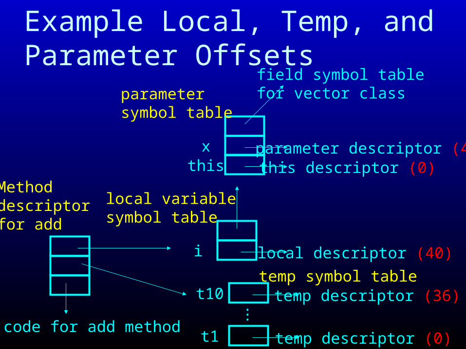
Example Local, Temp, and Parameter Offsets
this
i
this descriptor (0)
local descriptor (40)
field symbol tablefor vector class
local variablesymbol table
x
parametersymbol table
parameter descriptor (4)
code for add method
Method descriptorfor add
t1 temp descriptor (0)
temp symbol tablet10 temp descriptor (36)
..
.
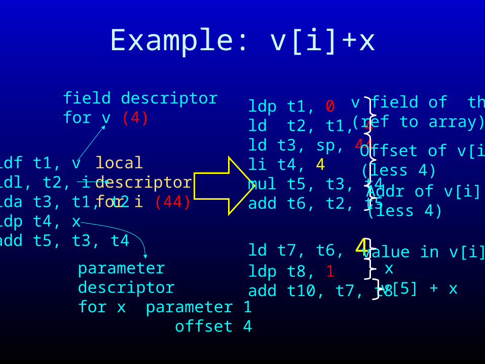
Example: v[i]+x
ldf t1, vldl, t2, i lda t3, t1, t2ldp t4, xadd t5, t3, t4
field descriptor for v (4)
parameter descriptorfor x parameter 1 offset 4
ldp t1, 0ld t2, t1, 4ld t3, sp, 44li t4, 4mul t5, t3, t4add t6, t2, t5
ld t7, t6, 4ldp t8, 1add t10, t7, t8
v field of this (ref to array)
Offset of v[i](less 4)Addr of v[i](less 4)
value in v[i]xv[5] + x
local descriptor for i (44)

Eliminating TempsUse (symbolic) registers and stack to eliminate temps
ldp t1, 0ld t2, t1, 4ld t3, sp, 44li t4, 4mul t5, t3, t4
ldp sr1, 0st sr1, sp, 0ld sr1, sp, 0ld sr2, sr1, 4st sr2, sp, 4ld sr1, sp, 44st sr1, sp, 8li sr1, 4st sr1, st, 12ld sr1, sp, 8ld sr2, sp, 12mul sr3, sr1, sr2st sr3, sp, 16t1 temp descriptor (0)
t10 temp descriptor (40)...
temp symbol table

Enter and Exit Nodes for add Method
void add(int x) {
int i;
...
}
• How big is stack frame for add? – 48 bytes (space for ra, i, 10 temps)– assuming 4 byte words
enter 48
exit 48
....

Sequence of PassesHigh Level IR
Replace Structured withUnstructured Flow of Control
Flatten Instruction Trees
Convert to Flat Address Space
Use Stack, Symbolic Registers To Eliminate Temps
Low Level IR

Low-Level IR Summary• Field Accesses Translate To ld or st nodes
– address is object pointer, offset is field offset
• Array Accesses Translate To ld or st nodes– address is array pointer + 4 + (index * element size)– Put length offset (4) in ld or st instruction
• Local Accesses Translate To ld or st nodes– address is sp, offset is local offset
• Parameter Accesses Translate To – lpd, stp instructions - specify parameter number
• Compute instructions use sr1, sr2, sr3 ONLY• Conditional branch instructions • Enter and Exit Nodes Specify Stack Frame Size• Very close to machine

Generating Machine Code
• Translate instructions in low-level IR to assembly
• Key complication: calling convention

Memory Layout
Stack
Text segment
Heap
locals, parameters, return addresses
0x7fffffff
0x400000Reserved
Data segment
dynamically allocated data (objects, arrays)
statically allocated data (global objects, arrays, variables)
code

Procedure Linkage
Standard procedure linkage
procedure p
prolog
epilog
pre-call
post-return
procedure q
prolog
epilog
Procedure has• standard prolog• standard epilog
Each call involves a• pre-call sequence• post-return sequence
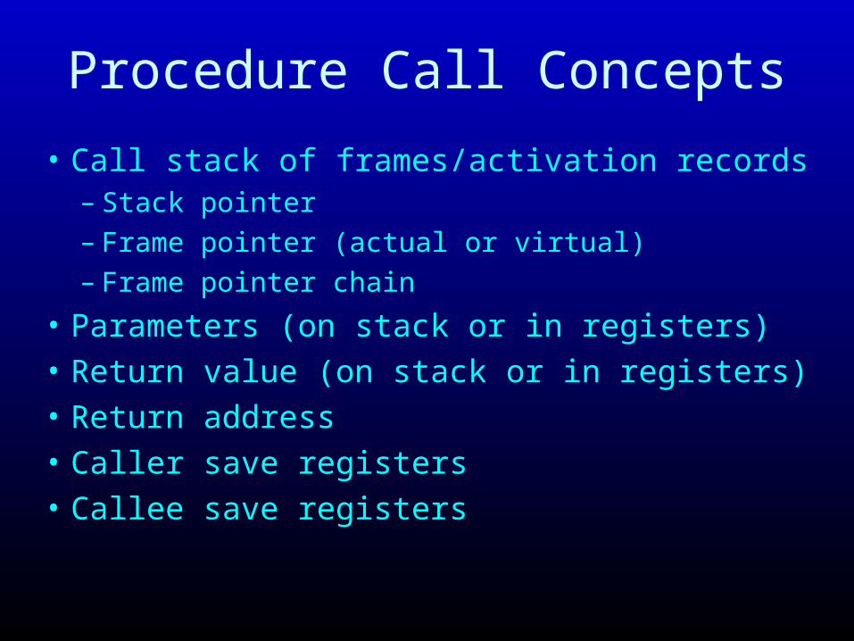
Procedure Call Concepts
• Call stack of frames/activation records– Stack pointer
– Frame pointer (actual or virtual)
– Frame pointer chain
• Parameters (on stack or in registers)• Return value (on stack or in registers)• Return address• Caller save registers• Callee save registers
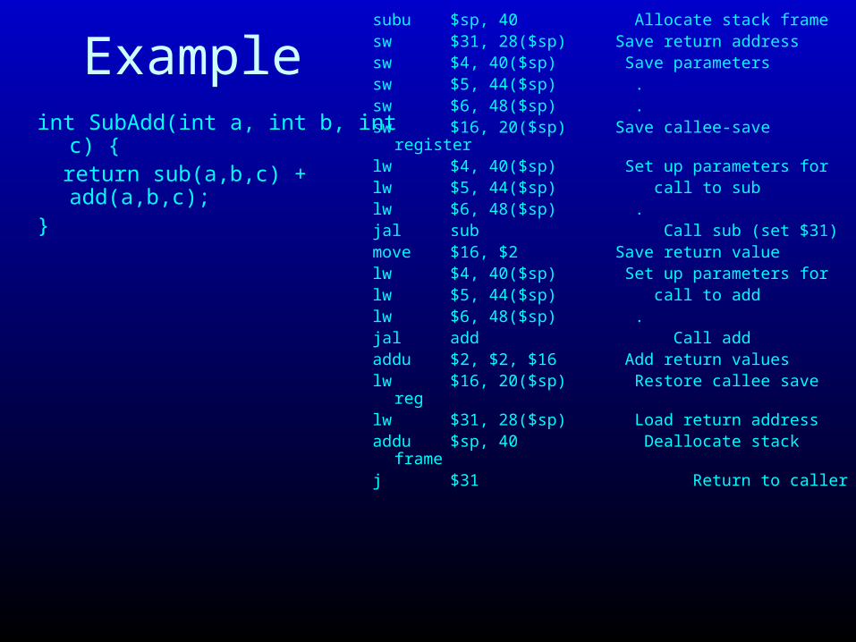
Examplesubu $sp, 40 Allocate stack framesw $31, 28($sp) Save return addresssw $4, 40($sp) Save parameterssw $5, 44($sp) .sw $6, 48($sp) .sw $16, 20($sp) Save callee-save registerlw $4, 40($sp) Set up parameters forlw $5, 44($sp) call to sublw $6, 48($sp) .jal sub Call sub (set $31)move $16, $2 Save return valuelw $4, 40($sp) Set up parameters forlw $5, 44($sp) call to addlw $6, 48($sp) .jal add Call addaddu $2, $2, $16 Add return valueslw $16, 20($sp) Restore callee save reglw $31, 28($sp) Load return addressaddu $sp, 40 Deallocate stack framej $31 Return to caller
int SubAdd(int a, int b, int c) { return sub(a,b,c) + add(a,b,c);}
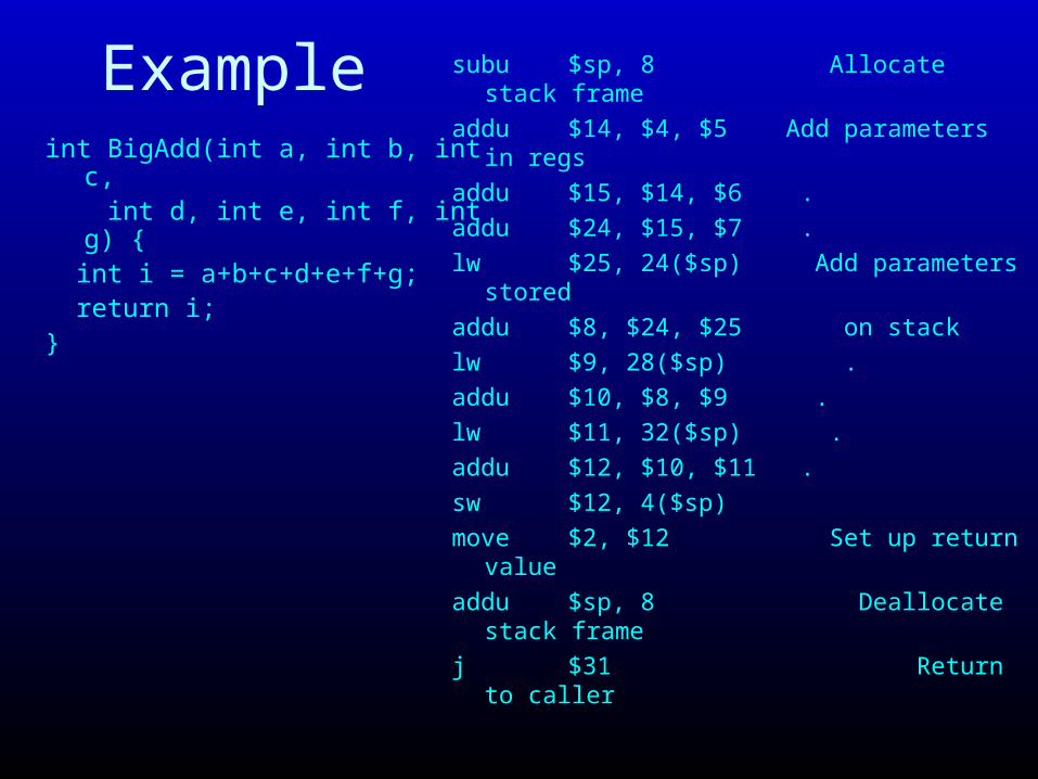
Example subu $sp, 8 Allocate stack frame
addu $14, $4, $5 Add parameters in regs
addu $15, $14, $6 .
addu $24, $15, $7 .
lw $25, 24($sp) Add parameters stored
addu $8, $24, $25 on stack
lw $9, 28($sp) .
addu $10, $8, $9 .
lw $11, 32($sp) .
addu $12, $10, $11 .
sw $12, 4($sp)
move $2, $12 Set up return value
addu $sp, 8 Deallocate stack frame
j $31 Return to caller
int BigAdd(int a, int b, int c, int d, int e, int f, int g) { int i = a+b+c+d+e+f+g; return i;}
Format of Activation RecordArgument N
Argument 0
...
Return Address (31)
Callee Save Registers
Local and TemporarySave Area
Arguments for Callee
ActivationRecord
fp (30)
sp (29)
or virtual fp
Space forALL args

Format of Activation RecordArgument N
Argument 0
...
Local and TemporarySave Area
Arguments for Callee
ActivationRecord
fp (30)
sp (29)
or virtual fp
What can compiler change?• For only one procedure?• If it compiles everything?
Space forALL args
Return Address (31)
Callee Save Registers

Procedure Call Actions• Pre-call
– Save any required caller-save registers – 8-15, 24, 25, 4-7 (args to caller)
– Set up arguments to callee – 4-7, stack arguments (space on stack for ALL arguments)
– jal or jalr – sets ra (31), jumps to callee
• Prolog– Allocate activation record - decrease sp (29)– Save any required callee-save registers - fp
(30), ra (31), 16-23– (Optional) set up frame pointer – decrease fp (30)
• Note: can eliminate fp

Procedure Call Actions• Retrieve parameters, compute result• Epilog
– Set up return value – regs 2,3– Restore callee-save registers - fp (30), ra (31), 16-23– Deallocate activation record - increase sp– Return – jr 31
• Post-return– Restore caller-save registers 8-
15, 24, 25, 4-7 (args to caller)– Retrieve result – regs 2, 3– Continue to compute

Leaf Procedure Optimizations
• Do not allocate activation record• Do not save fp, ra• Example
int sum(int a, int b) { return (a + b);}
addu $2, $4, $5 j $31
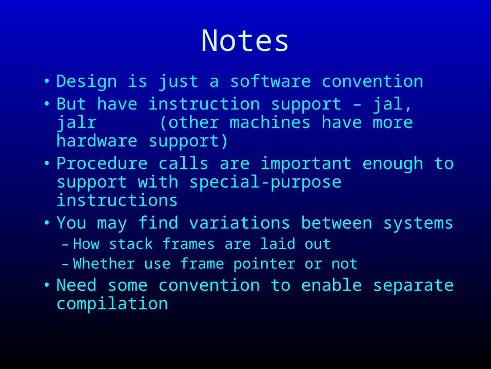
Notes• Design is just a software convention• But have instruction support – jal, jalr
(other machines have more hardware support)• Procedure calls are important enough to
support with special-purpose instructions• You may find variations between systems
– How stack frames are laid out– Whether use frame pointer or not
• Need some convention to enable separate compilation
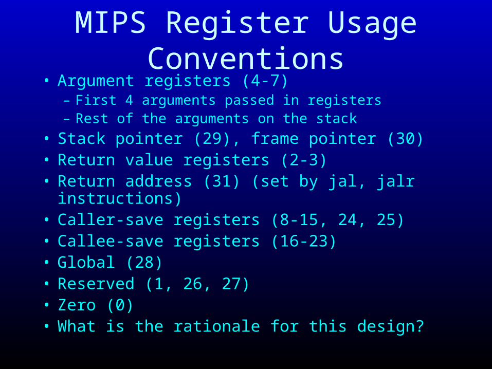
MIPS Register Usage Conventions• Argument registers (4-7)
– First 4 arguments passed in registers– Rest of the arguments on the stack
• Stack pointer (29), frame pointer (30)• Return value registers (2-3)• Return address (31) (set by jal, jalr instructions)• Caller-save registers (8-15, 24, 25)• Callee-save registers (16-23)• Global (28)• Reserved (1, 26, 27)• Zero (0)• What is the rationale for this design?

RationaleUse fp (30) for tracing stack frames for debugger Use at (1) for assembler temp – uses when generating code from assembly Have callee-save registers – caller uses these to hold values across procedure calls, if callee does not use them, eliminate saves of these registers Have caller-save registers – callee uses these first to hold temporary values if caller does not use them, eliminate saves of these registers Need both kinds for optimal code generation Arguments, return address, and return values stored in registers to avoid having to store and fetch from memory in common case Only have first four arguments in registers and rest on stack because need some bound on number of registers used for calling conventionWhy have global register gp (28)? To avoid inefficient address computations for global variables. Maybe can use immediate offsets off of gp instead Whole design is an exercise in make the common case fast
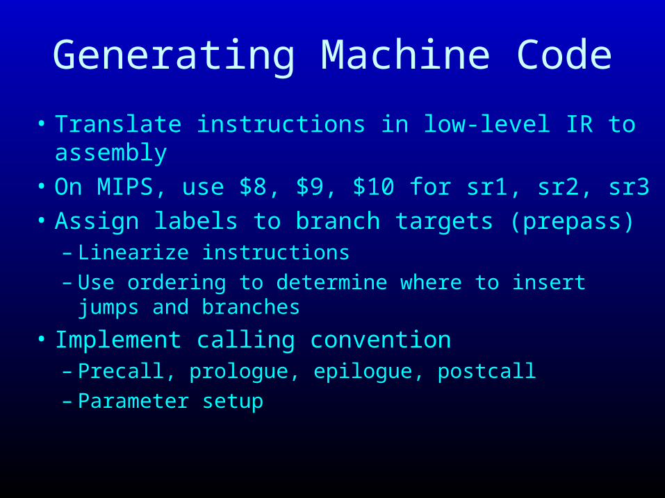
Generating Machine Code
• Translate instructions in low-level IR to assembly
• On MIPS, use $8, $9, $10 for sr1, sr2, sr3
• Assign labels to branch targets (prepass)– Linearize instructions– Use ordering to determine where to insert jumps and
branches
• Implement calling convention– Precall, prologue, epilogue, postcall– Parameter setup

Generating Machine Code
• entry nsubu $sp, n – allocate stack framesave return address ($31) on stacksave values in registers 4-7 (parameters) in stack
frame of caller
• exit nmove return values to registers 2, 3fetch return address ($31) from stackaddu $sp, n – deallocate stack framej $31 – return to caller

stp, ldp, call instructions
• stp n, sr– If 0 ≤ n ≤ 3, move sr (one of $8-$10) to $4-$7– Otherwise, store sr (one of $8-$10) to stack location
• ldp sr, n– If 0 ≤ n ≤ 3, move one of $4-$7 to sr (one of $8-$10)– Otherwise, load stack to sr (one of $8-$10)
• Call – jal to procedure• Postcall
– reload $4-$7 (parameters to caller) from stack

Ld, St, Ldrv, Compute
• Load and store instructions translate directly to– lw reg1, offset(reg2)– sw reg1, offset(reg2)
• ldrv instruction translates to a move of return value ($2,$3) to corresponding register
• Compute instructions (add, sub, mul, …) translate directly to compute instructions on machine

Branches and Jumps• Key issue: generating branches and branch target labels• Depth-first traversal
– Number nodes in a topological sort order– Will output generated instructions in that order
• Use numbering to generate label for each branch target• If a node n has successor s and label(n)+1≠label(s)
– Generate j label(s) after generate code for n • For a conditional branch br<cond> r1, (n1, n2) →
br<cond> r1, label(n1)j label(i2)
• If node n corresponds to branch target generate label(n): before generate code for n

Branches and Jumps
• Depth-first traversal to number nodes in a topological sort order
• Use numbers to generate label for each instruction• If node has single successor, jump to successor unless
successor has next number• For a conditional branch br<cond> r1, (i1, i2)
br<cond> r1, label(i1)
j label(i2) (omit if number(l2) = number + 1)
• Negating branch condition may produce better code• Branch delay slot issue

7: ldf t1, v8: ldl t2, i9: ldf t3, v10: ldl t4, i11: lda t5, t3, t412: ldp t6, x13: add t7, t5, t614: sta t7, t1, t2
2: ldl t8, i3: ldf t9, v4: len t10, t95: slt t11, t8, t10 6: brneqz t11
1: entry
15: exit
enter 48L2: ldl t8, ildf t9, vlen t10, t9slt t11, t8, t10 brneqz t11, L7j L15L7:ldf t1, vldl t2, ildf t3, vldl t4, ilda t5, t3, t4ldp t6, xadd t7, t5, t6sta t7, t1, t2j L2L15: exit 48
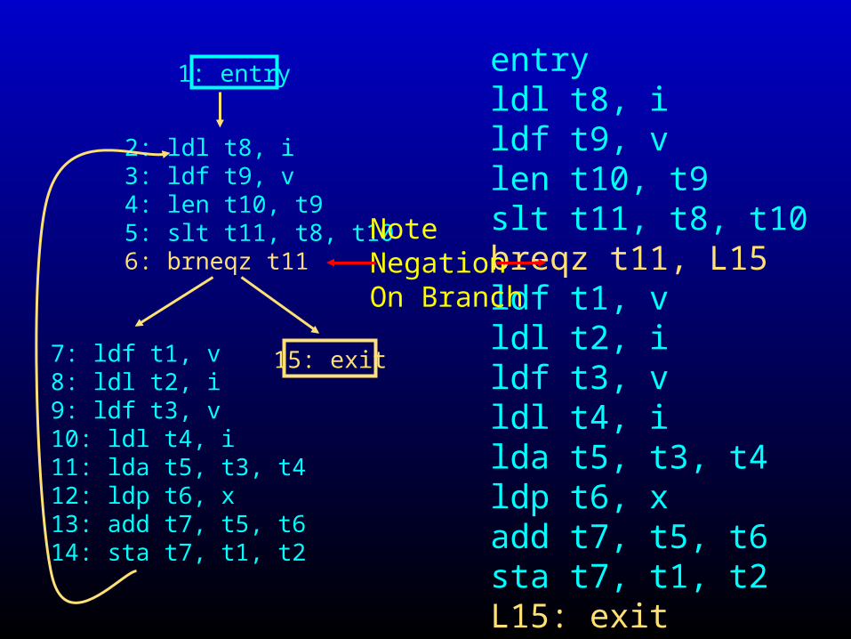
7: ldf t1, v8: ldl t2, i9: ldf t3, v10: ldl t4, i11: lda t5, t3, t412: ldp t6, x13: add t7, t5, t614: sta t7, t1, t2
2: ldl t8, i3: ldf t9, v4: len t10, t95: slt t11, t8, t10 6: brneqz t11
1: entry
15: exit
entryldl t8, ildf t9, vlen t10, t9slt t11, t8, t10 breqz t11, L15ldf t1, vldl t2, ildf t3, vldl t4, ilda t5, t3, t4ldp t6, xadd t7, t5, t6sta t7, t1, t2L15: exit
Note NegationOn Branch

Pseudo Instructions
• Look like instructions, but not in instruction set
• Expand to multiple instructions
bge reg1, reg2, offset – expands toslt $at, reg1, reg2
beqz $at, offset
li reg, value – loads value into reg, expansion depends on how big value is
less than 16 bits – ori reg, $0, value
more than 16 bits – multiple instructions

Summary• Translation from parse trees to high-level IR
– Preserves object structure– Preserves structured flow of control– Suitable for high-level analysis and optimization
• Translation from high-level IR to low-level IR– Flattens address space, eliminating object structure– Destructures flow of control constructs, replacing with
conditional branches
• Overall theme: move towards machine• Code generation: final step
– Should be straightforward if have done lowering well– Procedure calls, flow of control primary complications