miss jennifer bonesz mr. louie padilla
TRANSCRIPT

S P E C I A L R E P O R T
Sponsored by:
2009 2 www.chemicalprocessing.com
C o v e r S t o r yF l o w C o n t r o l
Inlet
OutletSupport Axis
Inlet Side
Outlet Side
Inlet Side Outlet Side
Curved Tube,No Flow
Inlet
Outlet
Twist Axis
Inlet Side
Outlet Side
Support Axis
Fluid ReacitveForce (Inlet)
Fluid ReacitveForce (Outlet)
Response to Flow
A discovery made by Gaspar Gustav de Co-riolis (1792-1843) in 1835 made possible the development of the highly accurate
dual curved-tube Coriolis flowmeter, and the more compact single straight-tube meter.
It was Napoleon who asked de Coriolis to ex-plain why his cannon balls never went straight. History doesn’t tell us whether he ever gave Na-poleon a good explanation - that phenomenon is caused by an entirely different effect - but de Co-riolis’ research led to his discovery of the Coriolis effect. A century or so later, Coriolis technology spawned a whole new family of accurate meters.
First, the weather reportMost people are familiar with the Coriolis effect on weather patterns. Because of the jet streams, the clouds tend to move east and west across the plan-et. However, the rotation of the planet creates the Coriolis effect, which deflects clouds as they move, causing them to spin or rotate. That cloud rotation causes the planet’s storms.
Applied to instrument design, Coriolis flowme-ters can measure mass flow directly, as well as volume and density. In process plants, mass is a vital measure-ment—the basis of all chemical reactions, mass and en-
ergy balances, and almost all process flow operations.Before the availability of Coriolis meters, mass
was measured by weighing liquids on a scale. This can be appropriate for batch process operations, but not for continuous processes. There, methods such as orifice plates and magnetic flow tubes measured only volumetric flow and required temperature and pressure corrections and calculations using addi-tional instruments to convert readings to mass.
Most volumetric flowmeters are affected by changes in the temperature, as well as by pres-sure, density, viscosity, and the flow profile of the process fluid. By comparison, a Coriolis flowme-ter provides a direct mass measurement that is un-affected by changing process fluid characteristics.
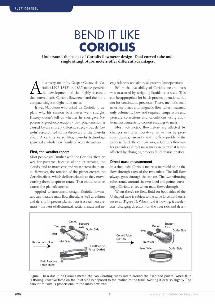
Direct mass measurement In a dual-tube Coriolis meter, a manifold splits the flow through each of the two tubes. The full flow always goes through the sensor. The two vibrating tubes rotate around the two fixed end points, creat-ing a Coriolis effect when mass flows through.
When there’s no flow, fluid on both sides of the U-shaped tube is subject to the same force, so there is no twist (Figure 1). When fluid is flowing, it acceler-ates (changing direction) on the inlet side and decel-
Bend It LIkeCoriolis
Understand the basics of Coriolis flowmeter design. Dual curved-tube and single straight-tube meters offer different advantages.
Figure 1.In a dual-tube Coriolis meter, the two vibrating tubes rotate around the fixed end points. When fluid is flowing, reactive force on the inlet side is opposed to the motion of the tube, twisting it ever so slightly. The amount of twist is proportional to the mass flow rate.

C o v e r S t o r y
www.chemicalprocessing.com 3 2009
F l o w C o n t r o l
Figure 2. To exploit the Coriolis phenomenon, a magnet is at-tached to one tube and a pickoff coil is attached to the other tube at the inlet and the outlet. Under flow conditions as the tubes twist, the generated sine waves shift apart. The instrument mea-sures the twisting, which is directly proportional to the mass flow.
TimeSensor or Signals, Response to flow
Inlet Side(C2)
TimeSensor or Signals,
No flow
OutletSide(C1)
UnibracketSupport
Flow Tubes
MagnetCoil
M M
Most volumetric flowmeters are affect-
ed by changes in the temperature, pres-
sure, density, viscosity and flow profile
of the process fluid. By comparison, a
Coriolis flowmeter provides a direct
mass measurement that is unaffected by
changing process fluid characteristics.
erates on the outlet side. As a result, reactive force on the inlet side is opposed to the motion of the tube, and reactive force on the outlet side operates in the same direction as the motion of the tube. The tube is twisted ever so slightly by these opposing forces. The amount of twist is proportional to the mass flow rate.
To exploit the Coriolis phenomenon, a magnet is attached to one tube and a pickoff coil is attached to the other tube at both the inlet and the outlet of both tubes (Figure 2). Because of vibration, the coil moves into the magnetic field and generates a sine wave proportional to that motion. Because the coils and magnets are referenced to each other (one element moves with each tube), the sine wave represents the relative velocity and position of the tubes. When the waves cross zero, the tubes are momentarily at rest before changing direction.
Under no-flow conditions, the two sine waves are in phase, or on top of each other. Under flow conditions as the tubes twist, these sine waves shift apart. The instrument measures the twisting, which is directly proportional to the mass flow.
Get it straightThe same analogy applies to a single straight-tube meter. The tube is vibrated along the center of the axis. Because the tube is fixed at the ends, the vibra-tion creates two rotating reference frames. The rota-
tion of the inlet side is in the opposite direction of the outlet side, creating the opposing Coriolis forces.
At the inlet side, the tube is rotating in one direc-tion, say upward, but the fluid is restrained by the wall and the substrate and now it is vibrating up, creating a force downward. When the fluid passes the centerline lengthwise and is rotating in the op-posite direction, the tube wall restricts the rotation, which creates a force in the opposite direction.
Figure 3 shows an exaggeration of the deflected shape. Here again, there are two forces proportional to the mass flow rate. The Coriolis effect is generated, as it is in the double curved tube, through the rotation of the tube about fixed ends. The two sine waves on the inlet and the outlet are shown as Point A and Point B in Figure 3. The inlet side lags the outlet side, which is identical for either straight or curved tubes.
Software allows designers of single straight-tube meters to ensure the response of the Coriolis signal is not affected by changes in the density or mount-ing options. The sensor element, which is relatively immune to environmental changes, takes into ac-count that the Coriolis forces are changing with fluid density at the appropriate vibration levels.

C o v e r S t o r y
2009 4 www.chemicalprocessing.com
F l o w C o n t r o l
Figure 3. The Coriolis effect is generated, as it is in the dou-ble curved tube, through the rotation of the tube about fixed ends. The two sine waves on the inlet and the outlet are shown as Point A and Point B. The inlet side lags the outlet side, which is identical for either straight or curved tubes.
Vibrating tube that has 2 axes of rotation, no flow or twist
Inlet axis ofrotation (RI)
Outlet axis ofrotation (RI)F = 0
m m
3 3
Distribution of forces, superimposed cause tube to deform
3 3F = -2m w x v
v
v
F
m
m
AB
y
t
A B
F
w w
The resulting force will cause points A and B to be out of phaseThe angle is proportional to mass flow rate
Each design has meritThere are similarities between dual, curved-tube and single, straight-tube meters, but also some significant differences. The key differences are how they behave to mounting effects, fluid density changes, and temperature changes.
The dual curved-tube meter is much more im-mune to meter-mounting variations. The two tubes are essentially identical. When they vibrate in op-position to each other, they are extremely well-balanced. All the energy is contained within these two tube sets, and nothing is transmitted out to the environment. The tubes are “unaware” of the envi-
ronment, because everything is maintained within the sensing elements themselves.
The same attributes make the dual curved-tube meter reliable despite fluid density changes. Because these two tubes are identical, when the fluid density changes within them, they respond identically.
These tubes extend from the pipeline and are relatively free to expand. Therefore, as the temperature changes, they grow in length, un-restrained, with no stresses or loads generated through expansion. A single measurement com-pensates for the effect of temperature on the modulus of the material. Dual curved-tube me-ters are also more sensitive to flow than lower profile, more compact meters.
In contrast, single straight-tube meter mount-ing presents challenges. The single-tube system was designed to be symmetric from inlet to out-let, but during vibration, the flow tube and ref-erence tube don’t vibrate to the same extent, so the single-tube meter is not inherently balanced. The reference part was designed to maintain that balance, but it responds to vibration as if no vi-bration leaked out the ends.
As fluid density changes, it only changes in a single tube, not in the reference tube. A great deal of research was invested to understand the dynamics and make these meters stable as fluid density chang-es. The design of the reference tube is vital for stable vibrations throughout the entire density range.
The most challenging design aspect of single straight-tube meters is dealing with temperature changes. Its case is fairly rigid, so it holds pipeline loads. It also holds the tube very rigidly. A fluid temperature change will change the tube, but the case will not allow it to expand.
Best useThe differences between curved tubes and straight tubes will impact user applications. Every plant or facility has a variety of needs for applications and measurement points, which often require signifi-cantly different specifications. One example would be a material balance, in which many different streams are combined. The output should be very consistent, but the error tends to increase as more streams are added together. In this case, users will
C o v e r S t o r y
www.chemicalprocessing.com 5 2009
F l o w C o n t r o l
TECHNICAL CHALLENGES Dual curved-tube meterMeter mounting effectsDual tubesMechanical filteringPipe loads through spacer
Single straight-tube meterSymmetric constructionLess mechanical filteringRigid caseAsymmetric vibrationLower sensitivity
FLUID DENSITY CHANGESDual curved-tube meterInherent well-balanced systemNo changes in tube vibration
Single straight-tube meterImposed balance systemChanges tube vibrationMass of tube changes
FLUID TEmpErATUrE CHANGESDual curved-tube meterFlow tubes not constrainedNo induced thermal stresses
Single straight-tube meterFlow tubes constrainedInduced thermal stresses
USEr NEEDSDual curved-tube meterSuperior accuracySuperior repeatabilitySuperior immunity to field effectsHigh turndownHigh and low flows sizes ( 1/10
inch to 6 inch)Optional materials of construction Gas applicationsCustody transfer
Single straight-tube meterCompactSanitarySelf-drainingInspectableNon-pluggingLow pressure dropCleanableShear sensitive fluidsSurface finishSecondary containment
Dual-TuBE vs. sTraiGhT-TuBE
The most challenging design aspect of
single straight-tube meters is dealing
with temperature changes.
want very high accuracy, because the errors will mul-tiply throughout the measurement points.
To solve this problem, the user could choose a dual curved-tube meter because of its ability to de-liver highly accurate and repeatable measurements. When blending or combining different materials, if operators are changing the amounts of materials that they are combining, they might add them at different flow rates. The dual curved-tube meter’s increased accuracy also gives it a higher rangeability, from 100 percent of flow to 2 or 3 percent of flow, with very little degradation of the measurement.
In some cases, when operators are just blending and filling, a mass measurement is required but it doesn’t need to have the same accuracy as in the material balance situation.
Despite the dual meter’s superiority, some us-ers will want to select the single straight-tube meter. If a volumetric meter is being replaced, there might be a limited amount of space to in-stall a new meter between closely spaced pipe flanges. The compactness of the straight tube might make it preferable. The straight tube is also easy to make highly sanitary.

C o v e r S t o r y
2009 6 www.chemicalprocessing.com
F l o w C o n t r o l
BoostIng BLendIngACCurACy
Optimizing operations using Coriolis technology
Coriolis flowmeters can help improve the accuracy of batch blending, dilution and continuous blending operations. These
meters sense the mass flow rate at a high degree of accuracy and sensitivity, transforming the rate into an analog, digital or frequency output.
Coriolis flowmeters offer chemical and other in-dustrial facilities on-line measurement of mass flow, density and volumetric flow. They have an accuracy of +/-0.05 percent and are capable of multivariable measurement ,” volume, mass, density and tempera-ture. Because they have no moving parts, mainte-nance requirements are reduced. They are available in a wide variety of sizes and flow capacities.
This article takes a look at some of the chal-lenges associated with batch blending, dilution and continuous blending operations, and examines how Coriolis flowmeters can improve mixing ac-curacy and cut downtime.
Batch blendingProper blending is important to many products because they need to have a specific taste, smell, texture, viscosity and/or appearance. For example, a slight error in ketchup blending can translate into dispensing problems at the dinner table.
Blending operations in the chemical indus-try produce different grades of finished products. Because many chemical facilities use the same equipment for multiple recipes, the equipment, in-strumentation and control valves must be able to operate with precision across a wide range.
Traditional batch blending, however, can ad-versely affect a chemical plant’s overall efficiencies in at least four ways.
First, the addition of one ingredient after an-other, called sequential addition, can amount to hours from the first addition to completion and transfer. Much of this time is required to expose the fluids to their reaction partners or to homog-enize a mixture.
Second, batch blending requires a great deal of valuable floor space for the large equipment.
Third, batch blending requires a larger finished-product storage area. Space must always be avail-able for the next batch transfer.
Finally, batch blending involves much more equipment than continuous blending. See Fig. 1.
The use of Coriolis meters can improve blend-ing operations, however, providing a highly accurate automated approach. In batch blending operations, the only measurement technique that can approach the accuracy of Coriolis meters is weigh cells. How-ever, for these cells to achieve a reasonable accuracy, a weighed tank must be supplied for each ingredi-ent, and concentrations of feed solutions must be ac-counted for, typically by density measurement.
Small additions cannot be accomplished accu-rately if a single large scale is used. If used, they can be expensive to maintain and keep in calibration. Agitators also affect weigh cells. Noise resulting from liquid turbulence must be filtered out. This equipment usage requires more maintenance than continuously operated smaller equipment.
Volumetric meters have a lower accuracy than coriolis meters, and some have longer ramp-up and decay periods, leading to inaccuracies, espe-cially in batching. Additional power is consumed for pumps and agitators, and more pressure and level instruments are needed.
DilutionsDilutions are a major blending application. House-hold, agricultural and other mixtures and solutions often have one or more concentrated or powerful components that are blended into an inert carrier, often high-purity water.
The reasons for dilution are many. Sodium hy-droxide and other caustics can be very viscous or even freeze in mild climates. Glacial acetic acid will freeze below 62 Degrees F. Hydrogen peroxide and other peroxides can react violently when the concentrated form is contaminated. Some reagents can be distrib-uted in more affordable piping systems when dilute. Accurate blending during dilution is important, therefore, to ensure performance and reduce cost.

C o v e r S t o r y
www.chemicalprocessing.com 7 2009
F l o w C o n t r o l
Feedlines
Feedlines
Rawmaterial
1
Rawmaterial
2
Rawmaterial
3
Pump
Pump
Pump
Rawmaterial
1
Rawmaterial
2
Rawmaterial
3
Pump
Pump
Pump Motor
Motor
Motor
Motor
Motor
Motor
Valve
Valve
Valve
Valve
Valve
Valve
Batch blending
Transferline
Pump
Productmeter
Product
Product
Stirredtank
Agitator
Continuous blending
Productmeter
(optional)In-line continuous mixer
Figure 1. Continuous blending requires smaller equipment, less floor space and a smaller product storage area than batch blending.
Somewhere, at the use points, composition is im-portant. The best place to dilute is as close to the un-loading point as possible. Using two Coriolis meters, purchased fluid, water and blended stream mass flow rates can be determined to less than 0.10 percent of rate inaccuracy, and density can be determined within 0.0005 gram per cubic centimeter (cc).
Plants potentially could handle their bills of lading and formulation needs at the same time. Plants even might be able to skip routine rail-car scale repair.
Continuous blendingReactions have many metering needs. The tradi-tional stirred batch reactor has not disappeared, but it has changed. In large part, competition has eliminated the separation stage after many reactors. It is much preferred to blend reactants precisely rather than to remove the overcharged component after reaction. Equipment and energy costs are eliminated, and the cycle often is improved.
The greater trend in reaction is continuous process-ing. With continuous blending, however, plants have only one chance to do it right. Rework is usually not an option, and co-incident precise ratios are a must.
For loop, stirred and plug flow continuous reactions, even pressure/temperature-compensated volumetric metering might not yield sufficient accuracy.
Continuous blending, measuring and mixing raw materials within the pipe as the material flows to produce exact proportions and meet specific recipe requirements, delivers the same accuracy as, or bet-ter accuracy than, batch blending.
Although continuous blending can alleviate many of the shortcomings of batch blending, some facili-ties resist the change because of their “corporate cul-ture.” Manufacturers like to stay within their comfort

C o v e r S t o r y
2009 8 www.chemicalprocessing.com
F l o w C o n t r o l
Figure 2. Coriolis meters offer volumetric flow, fluid temperature and density, and calculated density-type variables. Drawing cour-tesy of Micro Motion
zone and might be wary of an unfamiliar procedure. Moreover, many plants have invested heavily in batch blending equipment and are hesitant to replace it.
Return-on-investment (ROI) analysis could show the idled tankage could be used for surge or storage capacity. The changeover often is made after a con-tinuous expansion or de-bottlenecking has occurred.
One major benefit of continuous blending with automatic control is enhanced operator safety. The elimination of mix tanks reduces operator risk from material exposure, and eliminates both inert blan-keting of related vessels and entry permits. In addi-tion, continuous blending allows a smaller amount of hazardous materials at any one location.
Coriolis and continuous blendingOne processor of consumer products successfully in-stalled several lines of continuous blending modules. One stringent requirement of this processor is that the finished products must be perfect, with no variations in product quality. To help accomplish this, the pro-cessor decided to use only coriolis meters.
Typically, continuous blending units such as the one used by the consumer products processors are designed and shipped as pre-assembled and tested modules that measure about 12-feet (ft.) wide, 50-ft. long and 8-ft. high. Each module contains a coriolis meter and a metering valve for each ingredient, as
well as many transmitters for pressure and tempera-ture, static mixing, a control panel for the program-mable logic controller (PLC) and other instrumenta-tion. Spool pieces can be removed to make process changes or to add process analytical equipment.
Many continuous processes are in some respects batch processes in the sense that the modules could run for years without change. The consumer products processor actually has more process flexibility than that. Processing durations or operating rates can be adjusted to suit a just-in-time market; additional in-puts can be used for new ingredients or clean-in-place (CIP) fluids. The individual input line metering sys-tem can be used for detergent conservation and high-purity water.
Coriolis meters offer more than mass flow rate signals. They include volumetric flow, fluid tem-perature and density, and calculated density-type variables such as oBrix, oAPI and others. In addi-tion, a 4-20 mA direct current signal from a pres-sure transmitter can be fed into the flow transmitter and re-transmitted digitally, saving wiring. Fig. 2 shows a cutaway view of a coriolis flowmeter.
Some Coriolis meters might have “unadver-tised” capability, in the consumer product proces-sor’s case, a relative-viscosity calculated variable. Although not in standard units of poise, saybolt seconds universal (SSU) or stokes, the variable is relatively accurate and repeatable. It is an impor-tant quality variable. Any of these signals, as well as mass flow and density, can be transmitted. Hart, Modbus, Profibus PA and Foundation fieldbus are all available, depending on model selection.
ConclusionContinuous blending offers a time- and space-saving alternative to batch blending. When coriolis meters are used in an automatic-control continu-ous blending application, whether the application is an upgrade of an existing process or installation of a new process, chemical plants can:
Improve product quality.Enhance on-stream time.Optimize floor space.Reduce staffing costs.Improve safety.Improve process information from control system.Boost product delivery reliably.Minimize waste disposal.

C o v e r S t o r y
www.chemicalprocessing.com 9 2009
F l o w C o n t r o l
Process A premier global supplier of monomers, resins, and other specialty chemicals produces a wide range of coatings—more than 150 different chemical recipes, which are changed out fre-quently. The supplier runs more than a dozen lines, but this still represents more than 10 dif-ferent recipes per meter. This extreme variability places significant pressure on plant yields and profitability.
The supplier is a long-time user of Micro Motion Coriolis flow technology. They use the Coriolis flow measurement for accounting and yield calculations; they use the Coriolis density measurement for interface detection.
Challenge The supplier was using relatively older Micro Motion devices. Typically this is not a problem, because Micro Motion meters tend to be in ser-vice for many years without repair or mainte-nance requirements. However, as part of their operations, the supplier periodically steam-cleaned these meters (depending on product), so occasionally the meter would start empty. This would create a false output until the meter filled with product.
Operators were trained to watch for this false output, and would compensate by keeping flow valves shut. However, human error was on on-going problem. Inaccurate batches were result-ing in product rework, which meant lost time and money.
Furthermore, two operators normally took each meter offline for 4 to 8 hours each quarter to check
its calibration against a load cell. Raw material con-sumption was reduced by $200,000 in six months.
solution Newer Micro Motion meters are equipped with an “empty-full-empty” feature. In addition, the newer Micro Motion devices were far better at interface detection. The chemical supplier installed these new meters and observed the results for one year. They saw their yields im-prove. Raw material consumption was reduced by $200,000 in six months.
Additionally, the meter verification function of the new meters allowed the supplier to check the calibration of their meters every quarter without taking down the lines. This meant that two opera-tors were freed up for other duties, and the lines were essentially never down. The supplier believes they are saving at least $1000 per quarter due to the meter verification feature.
specIaLty chemIcaL company Upgrades mIcro motIon meters,
sAves $400,000 AnnuAlly

the rIght Flowmeter
2009 10 www.chemicalprocessing.com
It’s critical – for safety and operational ef-ficiency – to know precisely what flows through a chemical plant. Accurate monitor-
ing of what’s dosed into the reactor, transferred into the crystallizer, and at what temperature the fermentation tank is ensures the plant performs at its peak and there are no unexpected surprises. This monitoring and measuring is only as good and robust as the flowmeter technology used.
Choosing a flow measurement technology de-pends on a number of factors – cost, required ac-curacy, application, and what is being measured. No flowmeter is ideal for every application.
Volumetric flow can measured via several different principles. Differential pressure (DP) flow measure-ment is inferred by measuring the differential pressure across a restriction in the pipe. Volumetric flow can also be measured using positive displacement (PD) or turbine meters where a device rotates as a result of the flow passing over or around it. Both PD and turbine measurement devices are mechanical instruments
with moving parts that require maintenance and cali-bration checks to ensure they are working properly. In addition, both meters restrict the actual size of the internal pipe (because the meters take up room) and cause a pressure drop. DP flowmeters also require a relatively long run of straight pipe to ensure a good flow profile (10-35d).
Coriolis mass flow measurement technology uses a single principle, that when fluid is moving through an oscillating flow tube, the force causes the tube to twist. The amount of this twist is directly proportion-
al to the mass flow rate of the fluid flowing through the tube. In addition to providing direct mass flow measurement, Coriolis meters measure volume, liq-uid density and temperature – making it much more than a “flowmeter.” With no moving, internal parts, Coriolis meters require no maintenance or repair and don’t require flow conditioning or straight pipe runs.
Coriolis Measurement TechnologyEmerson’s Micro Motion introduced the first practi-cal Coriolis meter in 1977. For processes striving to maximize output, minimize waste, and reduce risk, the choice of high accuracy and reliable performance of Coriolis meters is ideal.
Two-Wire Coriolis MeasurementWhile the installations of Coriolis devices continues to expand, one area that has proved challenging is the im-plementation of Coriolis measurement in loop, or low power, applications. Historically, Coriolis meters have required four wires for operation – two wires to power the device and two for the instrument signal. Where four-wire Coriolis is ideally suited for new installation and measurement points, retrofitting a four-wire Corio-lis meter into existing, loop-powered applications has been challenging with the need to run additional cables and power to the site. That is, until now.
Emerson delivers a range of two-wire Micro Motion Coriolis measurement devices designed specifically for chemical and other process industry retrofit applications. This new platform enables the replacement and retrofit of existing two-wire flow devices with minimal effort and without incurring additional power or cabling costs. Better still, two-wire Coriolis measurement brings to processes the inherent benefits of direct mass measurement, no moving parts, online density monitoring, low pres-sure drop and no straight pipe run or flow condi-tioning required.
Micro Motion two-wire Coriolis meters are available in a range of sizes for line sizes ranging from 1/
8-in. (3mm) to 6-in. (150mm). These meters
deliver +/-0.10% liquid flow, +/-0.35% gas flow, and +/-0.0005 g/cm3 liquid density accuracy in continuous process and mass balance applications.
Learn more about 2-wire Coriolis at www.MicroMotion.com.
C o v e r S t o r yF l o w C o n t r o l
Loop-powErED, 2-wIrE CorIoLIS IDEAL For:
4-wIrE CorIoLIS opTImIzED For:
High performance basic process control
Peak performance in demanding applications
Internal accounting, allocation, mass balance
Batching from empty, applica-tions with entrained vapor/ gas
Where installation cost savings are substantial
Fiscal metering / custody transfer
Check meteringWhere on-board meter verification is needed

www.chemicalprocessing.com 11 2009
XXXXXXXXXXXXX
XXXXXXXXXXXXX
about the sponsor
Micro Motion introduced the first practical Coriolis meter for flow and density measure-ment in 1977. Since that time, our commitment to ongoing product development has enabled us to provide the highest performing measurement devices available.
Whether you have a highly demanding or a general process application, count on Micro Motion for stability, reliability and overall best performance.
Micro Motion, from Emerson Process Management, delivers a comprehensive range of flow and density measurement devices with outstanding transmitter architecture flexibility. Regard-less of the application - from precise, compact and drainable process control to large flow rate fiscal transfer - look no further than Micro Motion for the widest range of flow and density measurement solutions.
Emerson’s Micro Motion is committed to continuous improvement in its products, processes and people. This commitment is represented in everything we do. Allow your operation to ben-efit from expert field and technical application service and support made possible from more than 600,000 meters installed worldwide and over 30 years of flow and density measurement experience.
Emerson Process ManagementMicro Motion inc.
7070 Winchester CircleBoulder, Colorado 80301
800 522 6277 us & Canada+1 303 527 5200 international
www.MicroMotion.com
C o v e r S t o r yF l o w C o n t r o l
AR-001165
