mise-a-la-masse surveys at olkiluoto, 2006 - posiva · suomen malmi oy conducted mise-a-la-masse...
TRANSCRIPT

P O S I V A O Y
FI -27160 OLKILUOTO, F INLAND
Tel +358-2-8372 31
Fax +358-2-8372 3709
February 2007
Anna -Mar ia Ta rva inen
Work ing Repor t 2007 -06
Mise-a-la-Masse Surveysat Olkiluoto, 2006

February 2007
Base maps: ©National Land Survey, permission 41/MYY/07
Working Reports contain information on work in progress
or pending completion.
The conclusions and viewpoints presented in the report
are those of author(s) and do not necessarily
coincide with those of Posiva.
Anna -Mar i a Ta rva inen
Suomen Ma lm i Oy
Work ing Report 2007 -06
Mise-a-la-Masse Surveysat Olkiluoto, 2006

ABSTRACT Mise-a-la-Masse surveys at Olkiluoto, 2006 19.01.2007 Anna-Maria Tarvainen, Suomen Malmi Oy
Suomen Malmi Oy conducted Mise-a-la-Masse surveys at Olkiluoto site in
Eurajoki during November and December 2006. The surveys are a part of Posiva
Oy’s detailed investigation program for the final disposal of spent nuclear fuel.
The assignment included field work, data processing and technical raporting. The
report describes field operation, equipment as well as processing procedures and
shows the obtained results and an analysis of their quality in the appendices.
Data is delivered digitally in xyz-format.
Key words: Geophysics, borehole logging, structural geology, nuclear waste disposal

TIIVISTELMÄ Säköiset latauspotentiaalimittaukset Olkiluodossa vuonna 2006 19.01.2007 Anna-Maria Tarvainen, Suomen Malmi Oy
Suomen Malmi Oy teki latauspotentiaalmittauksia kairarei’issä K4…KR43 sekä
maanpinnalla Olkiluodon tutkimusalueella marras- ja jolukuussa 2006. Työ tehtiin
Posiva Oy:n tilauksesta osana yksityiskohtaisia kallioperätutkimuksia käytetyn
polttoaineen loppusijoitusta varten. Toimeksiantoon kuuluivat kenttätyöt,
latauspotentiaalimittausten prosessointi sekä tekninen raportointi. Raportissa on
kuvattu kenttätöiden kulku, käytetty kalusto, tuloskäsittely ja analyysi tulosten
laadusta. Tulokset on toimitettu tilaajalle digitaalisesti xyz-tiedostoina.
Avainsanat: Geofysiikka, reikämittaukset, rakennegeologia, ydinjätteen loppusijoitus

1
CONTENTS
Abstract
Tiivistelmä
Contents ............................................................................................................................1
1 Introduction ..............................................................................................................2
2 Equipment and methods ...........................................................................................3
3 Field work.................................................................................................................4
4 Conclusions ..............................................................................................................7
Preferences ...............................................................................................................8
Appendix 1: The Results of Mise-a-la-Masse measurements
Appendix 1.1 Investigation site .............................................................................10
Appendix 1.2 The Results of borehole measurements...........................................11
Appendix 1.3 The Results of surface measurements .............................................20
Appendix 2: Tool technical information
ABEM Terrameter SAS.........................................................................................25

2
1 INTRODUCTION
In 1999, Posiva Oy filled an application for a policy decision from the council of state
for a construction permit to build a final disposal facility for spent fuel at the Olkiluoto
area in the Eurajoki municipality. In December 2000, the Council of State made a
positive policy decision and in May 2001, the Parliament ratified the decision. The
policy makes it possible to concentrate the research activities at Olkiluoto.
Suomen Malmi Oy (Smoy) carried out Mise-a-la-Masse surface and borehole surveys
for Posiva Oy in November and December 2006 according to the purchase order
9140/06/TUAH. The aim of the surveys was to investigate conducting zones in
Olkiluoto investigation site, especially if these conducting zones extent to other
boreholes or to ground surface. The major zones were in boreholes KR4 and KR27, in
excavation area TK-13 and in ONKALO tunnel (PL899).
The field surveys were coordinated by geophysical foreman Antero Saukko. The data
processing and technical reporting was conducted by Anna-Maria Tarvainen. This
report describes field operation and data processing. The data interpretation is
introduced in a separate report by Tapio Lehtonen of Astrock Oy. The quality of the
results is shortly analysed and the data presented in the Appendices.

3
2 EQUIPMENT AND METHODS
Mise-a-la-Masse measurements can be carried out for example to investigate fracture,
crushed and conducting zones or ore bodies. Measurements are carried out with two
current and two potential electrodes. Both surface and borehole measurements are
possible. One current electrode is placed in contact with conducting body and another is
placed at large distance. The voltage distribution is measured around conducting body
using two electrodes of which one is fixed and another mobile.
The more specific description of Mise-a-la-Masse method can be found for example in
the previous Posiva Working Reports in relation to Mise-a-la-Masse surveys (Lehtonen,
T. and Heikkinen, E, 2004, Lehtonen, T., 2006, Paananen, M., 1996).
The borehole surveys were carried out using Smoy’s ABEM Terrameter SAS
Equipment. ABEM Terrameter SAS resistivity system consists of a transmitter-receiver
unit SAS 300 C and a separate booster SAS 2000 for the transmitter. It can be used as a
self-potential, a dipole-dipole or a Mise-a-la-Masse instrument. The output current can
be chosen from 0.2 mA to 200 mA. The input voltage range is from 0 to 500 V. More
technical information of the tool is presented in Appendix 2.

4
3 FIELD WORK
The field work was carried out within 20 working days in November and December
2006. The assignment consisted of measurements in 8 boreholes and on 15 surface
profiles. Current groundings were placed in boreholes KR4, KR27 and KR33, in trench
TK13 and ONKALO tunnel. The measurements were carried out in boreholes KR4,
KR8, KR9, KR27, KR33, KR40, KR41 and KR42 and KR43. The surface
measurements were carried out near to borehole KR27 (10 profiles) and trench TK-13
(5 profiles). The estimated total survey amount was 11 220 meters. The durations of the
field work are listed in Table 1. Table 2 and 3 shows measurement information. The
results of the measurements are presented in appendices 1.2 (borehole measurements)
and 1.3 (surface measurements). Data was processed using Gnuplot 4.0 software. Raw
data files were visualised and saved as pictures. Appendix 1.1 presents Olkiluoto
investigation site.
5
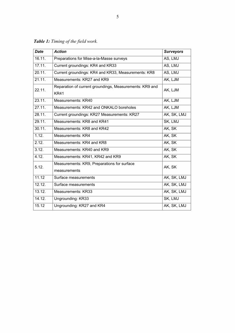
Table 1: Timing of the field work.
Date Action Surveyors
16.11. Preparations for Mise-a-la-Masse surveys AS, LMJ
17.11. Current groundings: KR4 and KR33 AS, LMJ
20.11. Current groundings: KR4 and KR33, Measurements: KR8 AS, LMJ
21.11. Measurements: KR27 and KR9 AK, LJM
22.11. Reparation of current groundings, Measurements: KR9 and
KR41 AK, LJM
23.11. Measurements: KR40 AK, LJM
27.11. Measurements: KR42 and ONKALO boreholes AK, LJM
28.11. Current groundings: KR27 Measurements: KR27 AK, SK, LMJ
29.11. Measurements: KR8 and KR41 SK, LMJ
30.11. Measurements: KR8 and KR42 AK, SK
1.12. Measurements: KR4 AK, SK
2.12. Measurements: KR4 and KR8 AK, SK
3.12. Measurements: KR40 and KR9 AK, SK
4.12. Measurements: KR41, KR42 and KR9 AK, SK
5.12. Measurements: KR9, Preparations for surface
measurements AK, SK
11.12 Surface measurements AK, SK, LMJ
12.12. Surface measurements AK, SK, LMJ
13.12. Measurements: KR33 AK, SK, LMJ
14.12. Ungrounding: KR33 SK, LMJ
15.12 Ungrounding: KR27 and KR4 AK, SK, LMJ
6
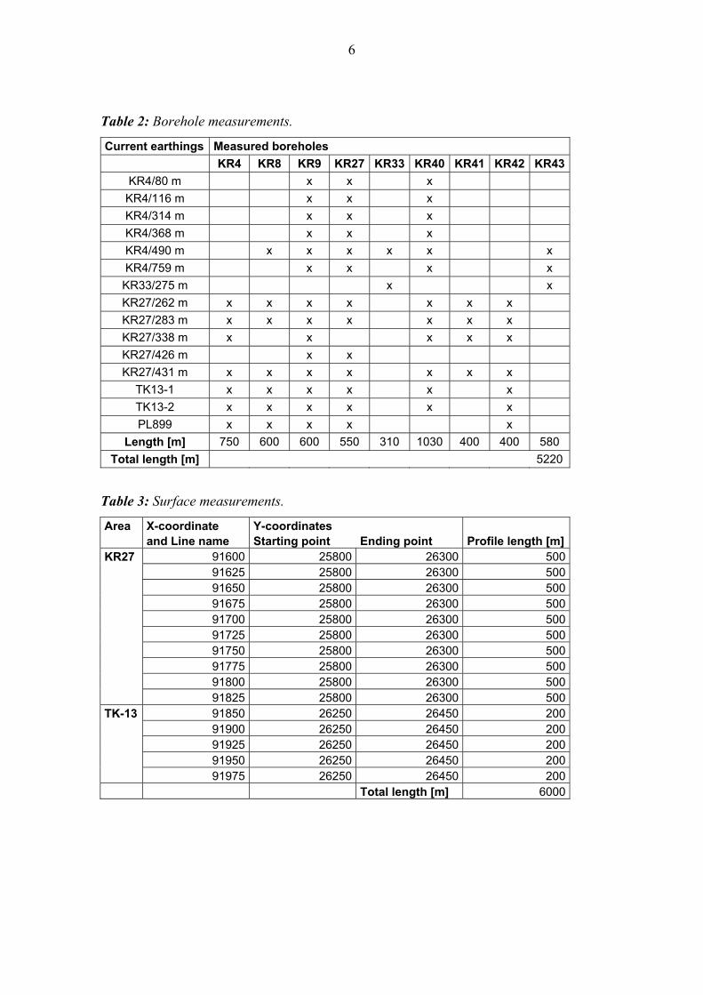
Table 2: Borehole measurements.
Current earthings Measured boreholes KR4 KR8 KR9 KR27 KR33 KR40 KR41 KR42 KR43
KR4/80 m x x x KR4/116 m x x x KR4/314 m x x x KR4/368 m x x x KR4/490 m x x x x x x KR4/759 m x x x x KR33/275 m x x KR27/262 m x x x x x x x KR27/283 m x x x x x x x KR27/338 m x x x x x KR27/426 m x x KR27/431 m x x x x x x x
TK13-1 x x x x x x TK13-2 x x x x x x PL899 x x x x x
Length [m] 750 600 600 550 310 1030 400 400 580 Total length [m] 5220
Table 3: Surface measurements.
Area X-coordinate Y-coordinates and Line name Starting point Ending point Profile length [m] KR27 91600 25800 26300 500 91625 25800 26300 500 91650 25800 26300 500 91675 25800 26300 500 91700 25800 26300 500 91725 25800 26300 500 91750 25800 26300 500 91775 25800 26300 500 91800 25800 26300 500 91825 25800 26300 500 TK-13 91850 26250 26450 200 91900 26250 26450 200 91925 26250 26450 200 91950 26250 26450 200 91975 26250 26450 200 Total length [m] 6000

7
4 CONCLUSIONS
Mise-a-la-Masse measurements in Olkiluoto were carried out during November and
December 2006. The task consisted of approximately 11 220 meters of measurements.
The results of Mise-a-la-Masse surveys are presented in Appendix 1.2 and 1.3. The
processed and interpreted data is delivered to the Client in digital format. The draft
report was compiled in January 2007.
The quality of the data widely achieves the required level. The quality was observed and
validated by client.

8
Preferences
ABEM Terrameter SAS Equipment Instruction Manual, Bromma, Sweden, Atlas Copco
AB.

9
Appendices

10
Appendix 1.1: Investigation site
Figure 1: Investigation site in Olkiluoto (red dots: boreholes K4…KR43)
11
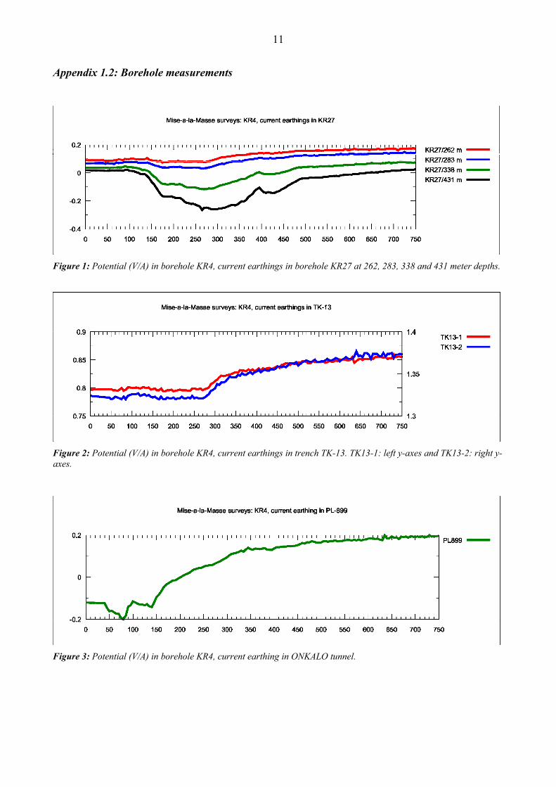
Appendix 1.2: Borehole measurements
Figure 1: Potential (V/A) in borehole KR4, current earthings in borehole KR27 at 262, 283, 338 and 431 meter depths.
Figure 2: Potential (V/A) in borehole KR4, current earthings in trench TK-13. TK13-1: left y-axes and TK13-2: right y-axes.
Figure 3: Potential (V/A) in borehole KR4, current earthing in ONKALO tunnel.

12
Figure 4: Potential (V/A) in borehole KR8, current earthing in borehole KR4 at 490 meter depth.
Figure 5: Potential (V/A) in borehole KR8, current earthing in borehole KR27 at 262, 283 and 431 meter depths.
Figure 6: Potential (V/A) in borehole KR8, current earthings in trench TK-13. TK13-1: left y-axes and TK13-2: right y-axes.
13
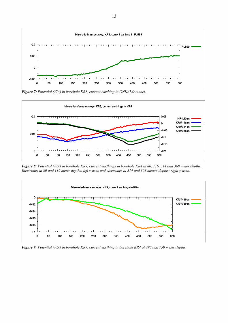
Figure 7: Potential (V/A) in borehole KR8, current earthing in ONKALO tunnel.
Figure 8: Potential (V/A) in borehole KR9, current earthings in borehole KR4 at 80, 116, 314 and 368 meter depths. Electrodes at 80 and 116 meter depths: left y-axes and electrodes at 314 and 368 meters depths: right y-axes.
Figure 9: Potential (V/A) in borehole KR9, current earthing in borehole KR4 at 490 and 759 meter depths.

14
Figure 10: Potential (V/A) in borehole KR9, current earthings in borehole KR27 at 262, 283, 338, 426 and 431 meter depths.
Figure 11: Potential (V/A) in borehole KR9, current earthings in trench TK-13. TK13-1: left y-axes and TK13-2: right y-axes.
Figure 12: Potential (V/A) in borehole KR9, current earthing in ONKALO tunnel.

15
Figure 13: Potential (V/A) in borehole KR27, current earthings in borehole KR4 at 80, 116, 314, 368, 490 and 759 meter depths.
Figure 14: Potential (V/A) in borehole KR27, current earthing in borehole KR27 at 262, 283, 426 and 431 meter depths.
Figure 15: Potential (V/A) in borehole KR27, current earthing in trench TK-13.

16
Figure 16: Potential (V/A) in borehole KR27 ,current earthing in ONKALO tunnel.
Figure 17: Potential (V/A) in borehole KR33 ,current earthings in borehole KR4 at 490 meter depth and in borehole KR33 in 275 meter depth.
Figure 18: Potential (V/A) in borehole KR40, earthing of current electrodes in borehole KR4 at 80, 116, 314 and 368 meter depths. Electrodes at 80 and 116 meter depths: left y-axes and electrodes at 314 and 368 meters depths: right y-axes.

17
Figure 19: Potential (V/A) in borehole KR40, current earthings in borehole KR4 at 490 and 759 meter depths.
Figure 20: Potential (V/A) in borehole KR40, current earthing in borehole KR27 262, 283, 338 and 431 meter depths.
Figure 21: Potential (V/A) in borehole KR40, current earthings in trench TK-13. TK13-1: left y-axes and TK13-2: right y-axes.

18
Figure 22: Potential (V/A) in borehole KR41, current earthings in borehole KR27 262, 283, 338 and 431 meter depths. 262 and 283 meter: left y-axes and 338 and 431 meter: right y-axes.
Figure 23: Potential (V/A) in borehole KR42, current earthings in trench TK-13. TK13-1: left y-axes and TK13-2: right y-axes.
Figure 24: Potential (V/A) in borehole KR42, current earthing in ONKALO tunnel.

19
Figure 25: Potential (V/A) in borehole KR43, current earthings in borehole KR4 490 and 759 meter depths.
Figure 26: Potential (V/A) in borehole KR43, current earthing in borehole KR33 at 275 meter depths.
Figure 27: Potential (V/A) in borehole ONKALO 1, current earthing in borehole KR4 at 116 meter depth.
20
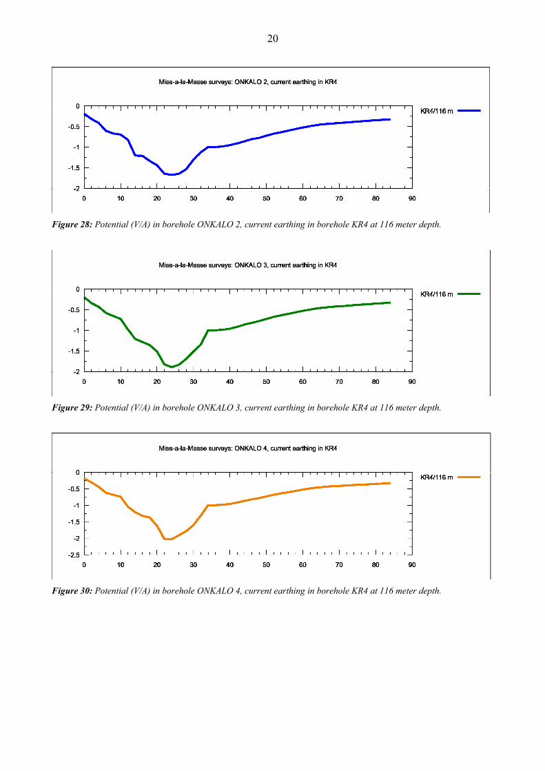
Figure 28: Potential (V/A) in borehole ONKALO 2, current earthing in borehole KR4 at 116 meter depth.
Figure 29: Potential (V/A) in borehole ONKALO 3, current earthing in borehole KR4 at 116 meter depth.
Figure 30: Potential (V/A) in borehole ONKALO 4, current earthing in borehole KR4 at 116 meter depth.

21
Appendix 1.3: Surface measurements
Figure 1: Potential (V/A) in line 91600, current earthing in borehole KR27 at 338 meter depth.
Figure 2: Potential (V/A) in line 91625, current earthing in borehole KR27 at 338 meter depth.
Figure 3: Potential (V/A) in line 91650, current earthing in borehole KR27 at 338 meter depth.

22
Figure 4: Potential (V/A) in line 91675, current earthing in borehole KR27 at 338 meter depth.
Figure 5: Potential (V/A) in line 91700, current earthing in borehole KR27 at 338 meter depth.
Figure 6: Potential (V/A) in line 91725, current earthing in borehole KR27 at 338 meter depth.

23
Figure 7: Potential (V/A) in line 91750, current earthing in borehole KR27 at 338 meter depth.
Figure 8: Potential (V/A) in line 91775, current earthing in borehole KR27 at 338 meter depth.
Figure 9: Potential (V/A) in line 91800, current earthing in borehole KR27 at 338 meter depth.

24
Figure 10: Potential (V/A) in line 91825, current earthing in borehole KR27 at 338 meter depth.
Figure 11: Potential (V/A) in line 91850, current earthings in trench TK-13.
Figure 12: Potential (V/A) in line 91900, current earthings in trench TK-13.

25
Figure 13: Potential (V/A) in line 91925, current earthings in trench TK-13.
Figure 14: Potential (V/A) in line 91950, current earthings in trench TK-13.
Figure 15: Potential (V/A) in line 91975, current earthings in trench TK-13.

26
Appendix 2: ABEM Terrameter SAS