mirrorcle technologies, inc. hardware guide
TRANSCRIPT
© 2018 Mirrorcle Technologies, Inc. Proprietary and Confidential. All rights reserved.
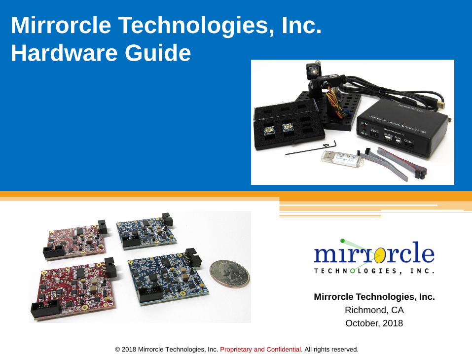
Mirrorcle Technologies, Inc.
Richmond, CA
October, 2018
Mirrorcle Technologies, Inc.
Hardware Guide

© 2018 Mirrorcle Technologies, Inc. Proprietary and Confidential. All rights reserved. 2
MTI Hardware Categories
Development Kits
MEMS Controllers
USB MEMS Controller “USB-SL MZ”
◼ Standard, boxed version
◼ OEM Version
USB MEMS Controller “OCCIE 1.x”
◼ OEM Version only (includes min. qty.)
MEMS Drivers
Digital Input – “PicoAmp”
Analog Input – “BDQ PicoAmp”

© 2018 Mirrorcle Technologies, Inc. Proprietary and Confidential. All rights reserved. 3
Layers of Abstraction in MEMS Mirror Control
Convert low voltage waveforms to
conditioned high-voltage waveforms
for MEMS driving
Receive (USB) commands and data,
buffer and output waveforms to
MEMS driver and peripherals
Prepare waveforms from user inputs
(interpolations, conditioning,
software filtering, etc), communicate
with firmware (Controller).
Deve
lop
ment
Kit
MEM
S C
ont
rolle
rM
SS
© 2018 Mirrorcle Technologies, Inc. Proprietary and Confidential. All rights reserved.
Development Kits
© 2018 Mirrorcle Technologies, Inc. Proprietary and Confidential. All rights reserved. 5
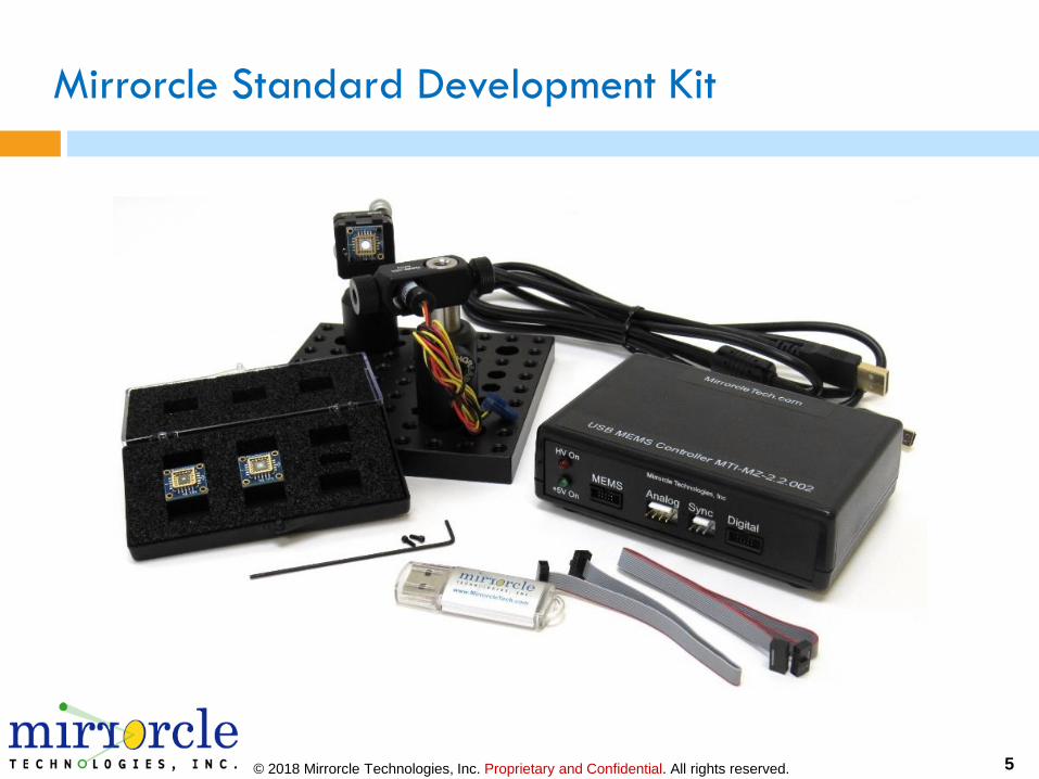
Mirrorcle Standard Development Kit
© 2018 Mirrorcle Technologies, Inc. Proprietary and Confidential. All rights reserved. 6
Standard Development Kit - Contents
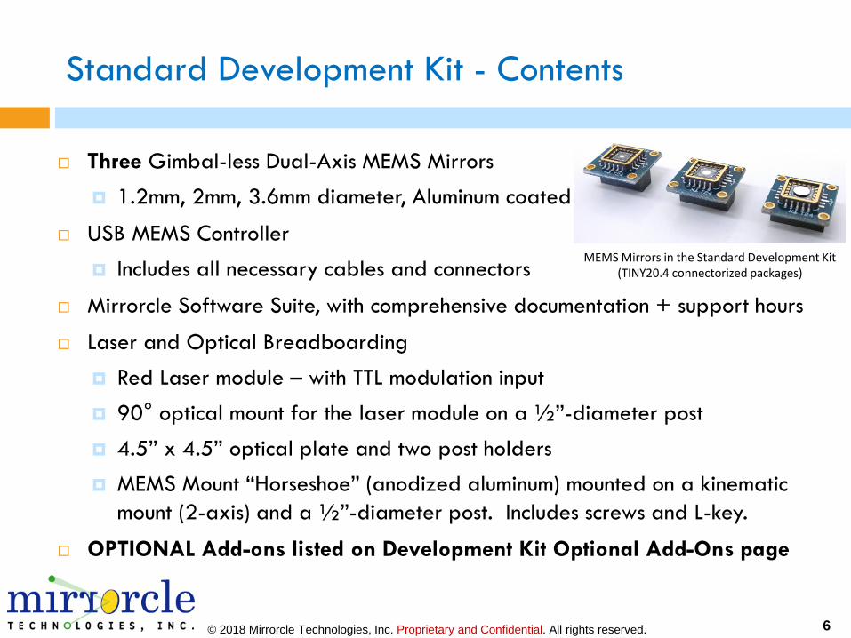
Three Gimbal-less Dual-Axis MEMS Mirrors
1.2mm, 2mm, 3.6mm diameter, Aluminum coated
USB MEMS Controller
Includes all necessary cables and connectors
Mirrorcle Software Suite, with comprehensive documentation + support hours
Laser and Optical Breadboarding
Red Laser module – with TTL modulation input
90° optical mount for the laser module on a ½”-diameter post
4.5” x 4.5” optical plate and two post holders
MEMS Mount “Horseshoe” (anodized aluminum) mounted on a kinematic
mount (2-axis) and a ½”-diameter post. Includes screws and L-key.
OPTIONAL Add-ons listed on Development Kit Optional Add-Ons page
MEMS Mirrors in the Standard Development Kit(TINY20.4 connectorized packages)
© 2018 Mirrorcle Technologies, Inc. Proprietary and Confidential. All rights reserved. 7
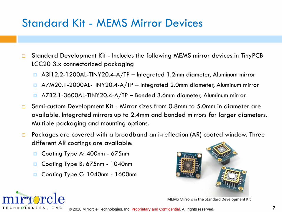
Standard Kit - MEMS Mirror Devices
Standard Development Kit - Includes the following MEMS mirror devices in TinyPCB
LCC20 3.x connectorized packaging
A3I12.2-1200AL-TINY20.4-A/TP – Integrated 1.2mm diameter, Aluminum mirror
A7M20.1-2000AL-TINY20.4-A/TP – Integrated 2.0mm diameter, Aluminum mirror
A7B2.1-3600AL-TINY20.4-A/TP – Bonded 3.6mm diameter, Aluminum mirror
Semi-custom Development Kit - Mirror sizes from 0.8mm to 5.0mm in diameter are
available. Integrated mirrors up to 2.4mm and bonded mirrors for larger diameters.
Multiple packaging and mounting options.
Packages are covered with a broadband anti-reflection (AR) coated window. Three
different AR coatings are available:
Coating Type A: 400nm - 675nm
Coating Type B: 675nm - 1040nm
Coating Type C: 1040nm - 1600nm
MEMS Mirrors in the Standard Development Kit
© 2018 Mirrorcle Technologies, Inc. Proprietary and Confidential. All rights reserved. 8
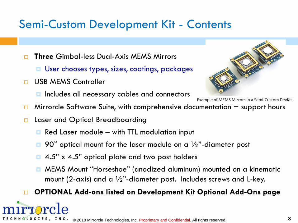
Semi-Custom Development Kit - Contents
Three Gimbal-less Dual-Axis MEMS Mirrors
User chooses types, sizes, coatings, packages
USB MEMS Controller
Includes all necessary cables and connectors
Mirrorcle Software Suite, with comprehensive documentation + support hours
Laser and Optical Breadboarding
Red Laser module – with TTL modulation input
90° optical mount for the laser module on a ½”-diameter post
4.5” x 4.5” optical plate and two post holders
MEMS Mount “Horseshoe” (anodized aluminum) mounted on a kinematic
mount (2-axis) and a ½”-diameter post. Includes screws and L-key.
OPTIONAL Add-ons listed on Development Kit Optional Add-Ons page
Example of MEMS Mirrors in a Semi-Custom DevKit
© 2018 Mirrorcle Technologies, Inc. Proprietary and Confidential. All rights reserved. 9
Development Kit – Optional Add-ons
Wireless Option – Custom designed and built afocal lens with 3 lens elements that
will magnify the optical scan-angles of the system by approximately 3X.
PSD Bundle – Includes PSD Module (with 20mm x 20mm duo-lateral Position Sensing
Device) and add-ons to the Matlab SDK for creating Look-Up-Tables, characterizing
MEMS devices, etc.
Wide-Angle-Lens – Multi-element afocal lens to magnify optical angles ~3X
Laser Tracking Bundle – Includes a photo sensor with multistage amplifier, reflective
tape, software upgrade, code examples and documentation
Android Development Kit – Includes the ‘Wireless Option’ Add-on, an Android
Tablet with preloaded sample Apps, and an Android SDK with documentation
Linux Development Kit – Includes a Raspberry Pi with MicroSD card preloaded with
Linux based OS, sample applications and a C++ SDK with documentation
Python Software Development Kit – Additional SDK for development using Python
language with the same functionality and capability of the Windows-based C++
SDK. Includes a library of functions and multiple example scripts.

© 2018 Mirrorcle Technologies, Inc. Proprietary and Confidential. All rights reserved. 10
Development Kits - MEMS Mirror Packages and Mounts
See detailed MEMS Packages and Mounts Guide:http://mirrorcletech.com/pdf/Mirrorcle_MEMS_Packages_and_Mounts_Guide.pdf
© 2018 Mirrorcle Technologies, Inc. Proprietary and Confidential. All rights reserved. 11
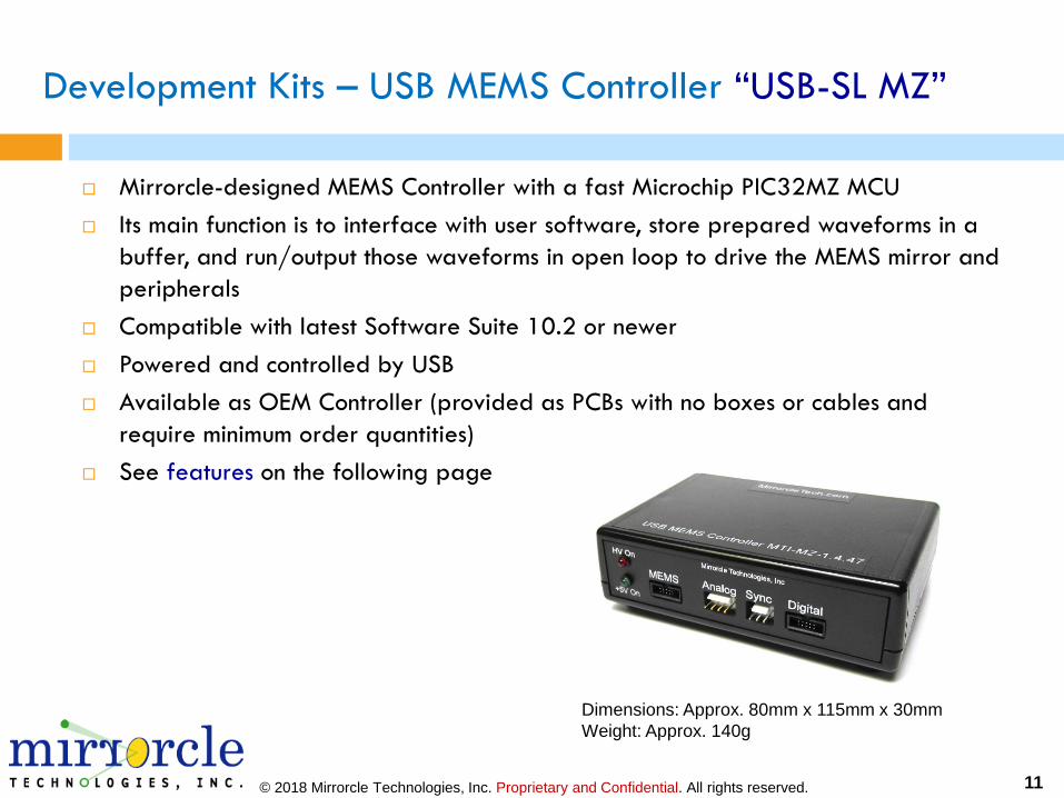
Development Kits – USB MEMS Controller “USB-SL MZ”
Mirrorcle-designed MEMS Controller with a fast Microchip PIC32MZ MCU
Its main function is to interface with user software, store prepared waveforms in a
buffer, and run/output those waveforms in open loop to drive the MEMS mirror and
peripherals
Compatible with latest Software Suite 10.2 or newer
Powered and controlled by USB
Available as OEM Controller (provided as PCBs with no boxes or cables and
require minimum order quantities)
See features on the following page
Dimensions: Approx. 80mm x 115mm x 30mm
Weight: Approx. 140g
© 2018 Mirrorcle Technologies, Inc. Proprietary and Confidential. All rights reserved. 12
USB-SL MZ - Controller Features
4x (16-bit) (0V-200V) Analog Outputs for X and Y axis control of MEMS mirrors
Programmable hardware-based low-pass filters and protection circuitry to reduce the
chances of device damage
Output bandwidth from 50Hz to 25kHz (governed by programmable filters)
8x Correlated Digital Outputs (3.3V) for controlling other components or systems
Sample Rates up to 120,000 samples per second (120 kSPS)
500kB of Onboard RAM allows up to 100,000 samples to be stored
2x (12-bit) Analog Inputs with +/- 10V input range
Flash Memory allows storage of settings and data for stand-alone operation (no PC)
Sync Port for synchronization with additional Controllers or driving of laser peripherals
<850mW Power Consumption in all modes
USB Plug and Play support
Separate analog input port for tracking photosensor (Laser Tracking Bundle Add-On)
Wireless Option Add-On allows battery-run wireless operation over Bluetooth
© 2018 Mirrorcle Technologies, Inc. Proprietary and Confidential. All rights reserved. 13
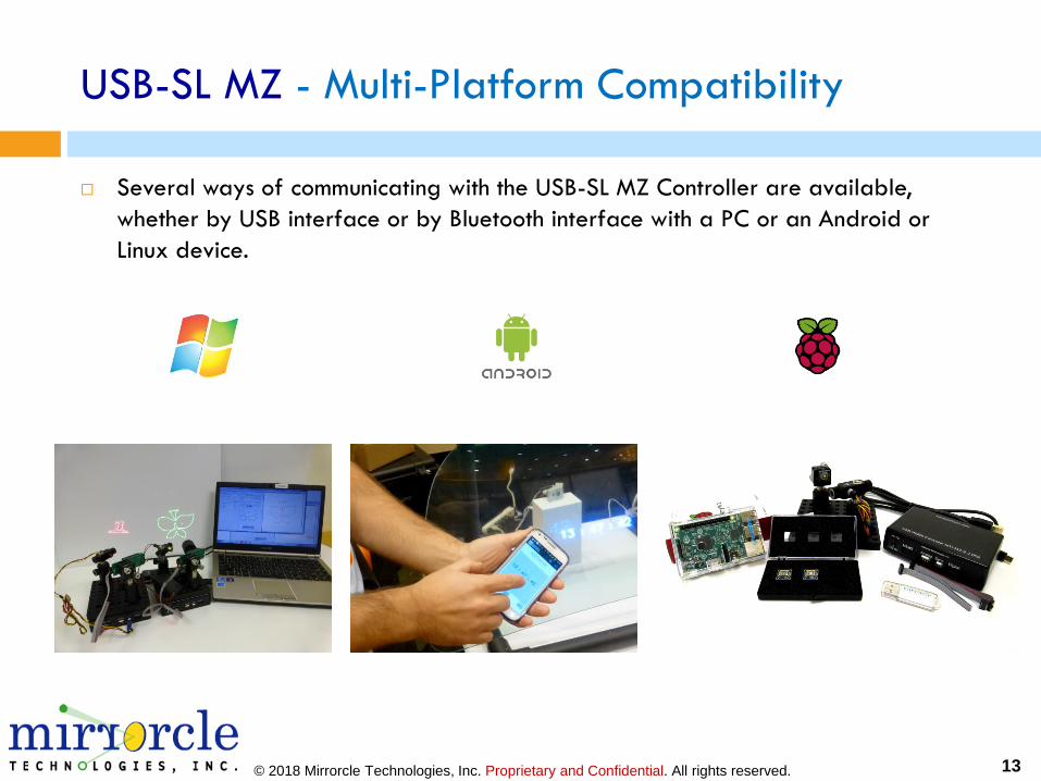
USB-SL MZ - Multi-Platform Compatibility
Several ways of communicating with the USB-SL MZ Controller are available,
whether by USB interface or by Bluetooth interface with a PC or an Android or
Linux device.
© 2018 Mirrorcle Technologies, Inc. Proprietary and Confidential. All rights reserved. 14
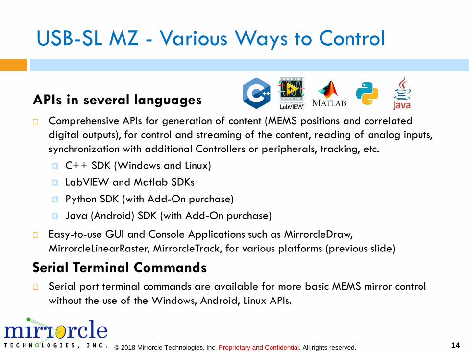
USB-SL MZ - Various Ways to Control
APIs in several languages
Comprehensive APIs for generation of content (MEMS positions and correlated
digital outputs), for control and streaming of the content, reading of analog inputs,
synchronization with additional Controllers or peripherals, tracking, etc.
C++ SDK (Windows and Linux)
LabVIEW and Matlab SDKs
Python SDK (with Add-On purchase)
Java (Android) SDK (with Add-On purchase)
Easy-to-use GUI and Console Applications such as MirrorcleDraw,
MirrorcleLinearRaster, MirrorcleTrack, for various platforms (previous slide)
Serial Terminal Commands
Serial port terminal commands are available for more basic MEMS mirror control
without the use of the Windows, Android, Linux APIs.
© 2018 Mirrorcle Technologies, Inc. Proprietary and Confidential. All rights reserved. 15
Development Kits - Mirrorcle Software Suite
The Mirrorcle Software Suite (“MSS”) comes with Windows
Applications and software development kits (SDK)
Applications:
MirrorcleDraw – Windows Application
MirrorcleLinearRaster – Windows Application
MirrorcleListDevices – Windows Application
MTIDevice-Demo – Windows Application (made from SDK example)
Development:
C++ SDK
Matlab SDK
LabView SDK
© 2018 Mirrorcle Technologies, Inc. Proprietary and Confidential. All rights reserved. 16
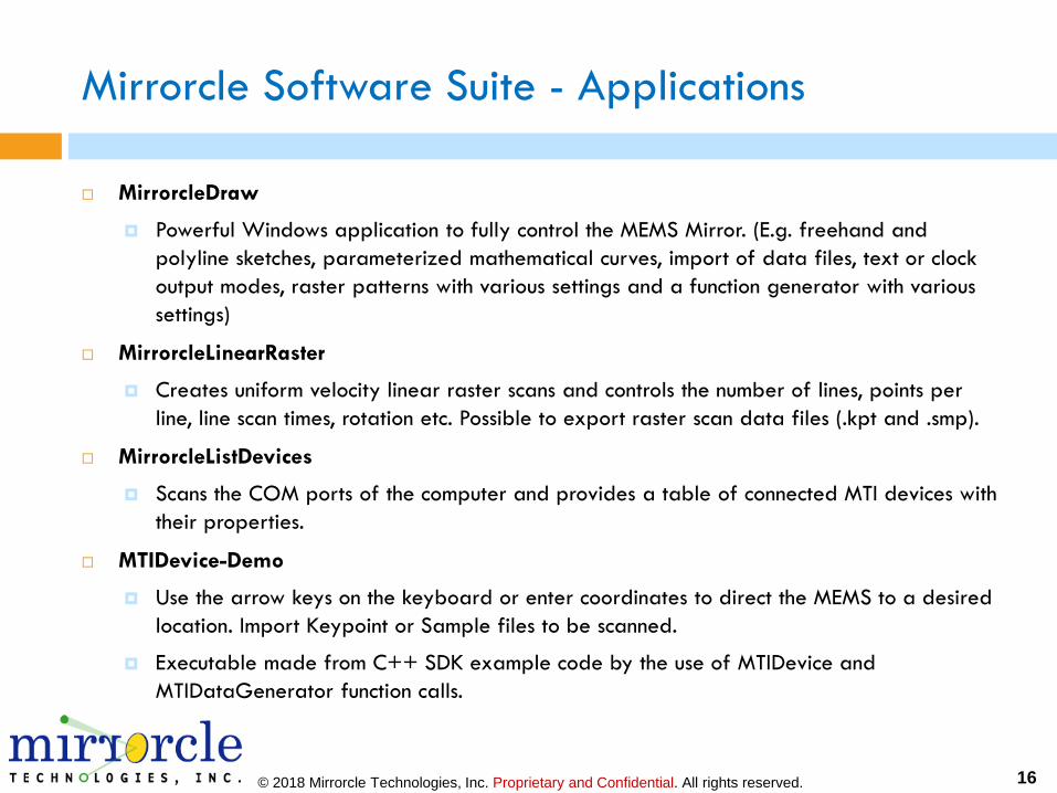
Mirrorcle Software Suite - Applications
MirrorcleDraw
Powerful Windows application to fully control the MEMS Mirror. (E.g. freehand and
polyline sketches, parameterized mathematical curves, import of data files, text or clock
output modes, raster patterns with various settings and a function generator with various
settings)
MirrorcleLinearRaster
Creates uniform velocity linear raster scans and controls the number of lines, points per
line, line scan times, rotation etc. Possible to export raster scan data files (.kpt and .smp).
MirrorcleListDevices
Scans the COM ports of the computer and provides a table of connected MTI devices with
their properties.
MTIDevice-Demo
Use the arrow keys on the keyboard or enter coordinates to direct the MEMS to a desired
location. Import Keypoint or Sample files to be scanned.
Executable made from C++ SDK example code by the use of MTIDevice and
MTIDataGenerator function calls.
© 2018 Mirrorcle Technologies, Inc. Proprietary and Confidential. All rights reserved. 17
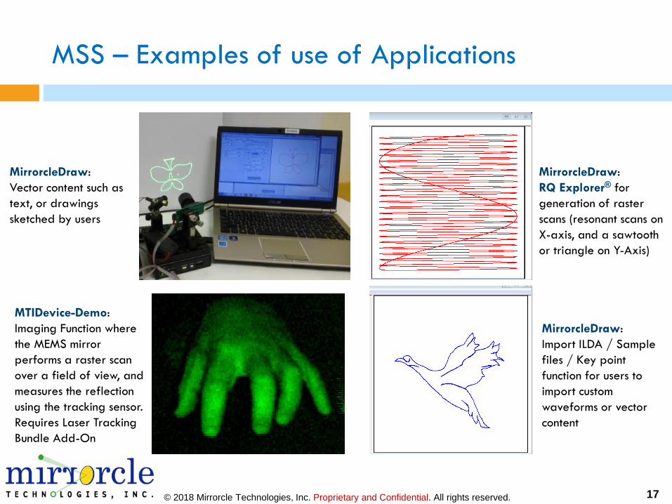
MSS – Examples of use of Applications
MirrorcleDraw:
Vector content such as
text, or drawings
sketched by users
MirrorcleDraw:
RQ Explorer® for
generation of raster
scans (resonant scans on
X-axis, and a sawtooth
or triangle on Y-Axis)
MTIDevice-Demo:
Imaging Function where
the MEMS mirror
performs a raster scan
over a field of view, and
measures the reflection
using the tracking sensor.
Requires Laser Tracking
Bundle Add-On
MirrorcleDraw:
Import ILDA / Sample
files / Key point
function for users to
import custom
waveforms or vector
content

© 2018 Mirrorcle Technologies, Inc. Proprietary and Confidential. All rights reserved. 18
Mirrorcle Software Suite - SDKs
C++ based Software Development Kit
The Software Development Kit (SDK) of the Mirrorcle Software Suite allows users
to develop their own applications.
C++ API - The interface provides classes and functions for analog output, control
of laser output, sample rate, filter settings, amplitude, device communication, etc.
An example Visual C++ project is provided to illustrate the use of the API and
several ways of driving devices in point-to-point, rastering, and other modes.
Matlab-based Software Development Kit
Similar to the C++ version, this is a Matlab-based software development kit
(SDK) allows the user the fastest and easiest route to development of
micromirror applications. Multiple examples included.
LabView-based Software Development Kit
Includes multiple examples of content generation (and content importing) and
driving of MEMS mirror devices from National Instruments LabView software.
© 2018 Mirrorcle Technologies, Inc. Proprietary and Confidential. All rights reserved. 19
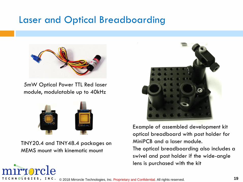
Laser and Optical Breadboarding
5mW Optical Power TTL Red laser
module, modulatable up to 40kHz
Example of assembled development kit
optical breadboard with post holder for
MiniPCB and a laser module.
The optical breadboarding also includes a
swivel and post holder if the wide-angle
lens is purchased with the kit
TINY20.4 and TINY48.4 packages on
MEMS mount with kinematic mount
© 2018 Mirrorcle Technologies, Inc. Proprietary and Confidential. All rights reserved. 20
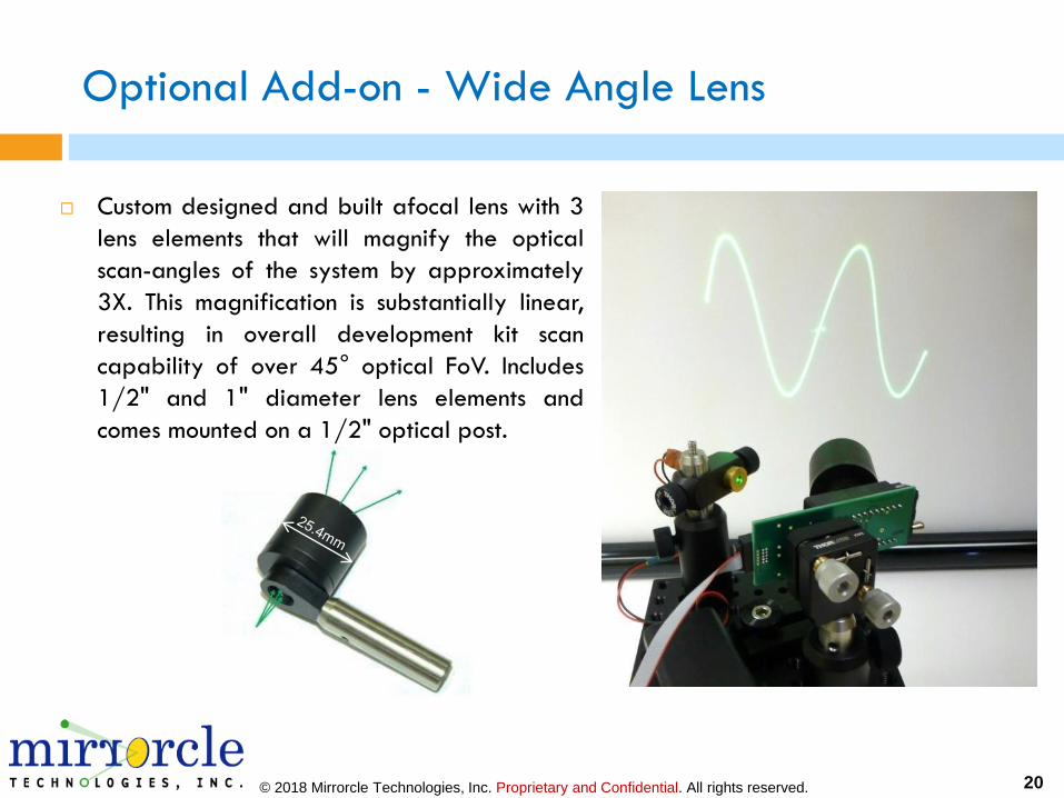
Optional Add-on - Wide Angle Lens
Custom designed and built afocal lens with 3
lens elements that will magnify the optical
scan-angles of the system by approximately
3X. This magnification is substantially linear,
resulting in overall development kit scan
capability of over 45° optical FoV. Includes
1/2" and 1" diameter lens elements and
comes mounted on a 1/2" optical post.
© 2018 Mirrorcle Technologies, Inc. Proprietary and Confidential. All rights reserved. 21
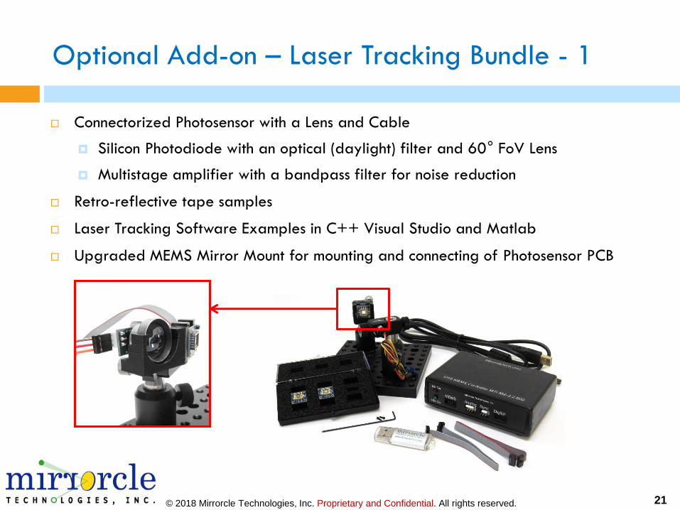
Optional Add-on – Laser Tracking Bundle - 1
Connectorized Photosensor with a Lens and Cable
Silicon Photodiode with an optical (daylight) filter and 60° FoV Lens
Multistage amplifier with a bandpass filter for noise reduction
Retro-reflective tape samples
Laser Tracking Software Examples in C++ Visual Studio and Matlab
Upgraded MEMS Mirror Mount for mounting and connecting of Photosensor PCB
© 2018 Mirrorcle Technologies, Inc. Proprietary and Confidential. All rights reserved. 22
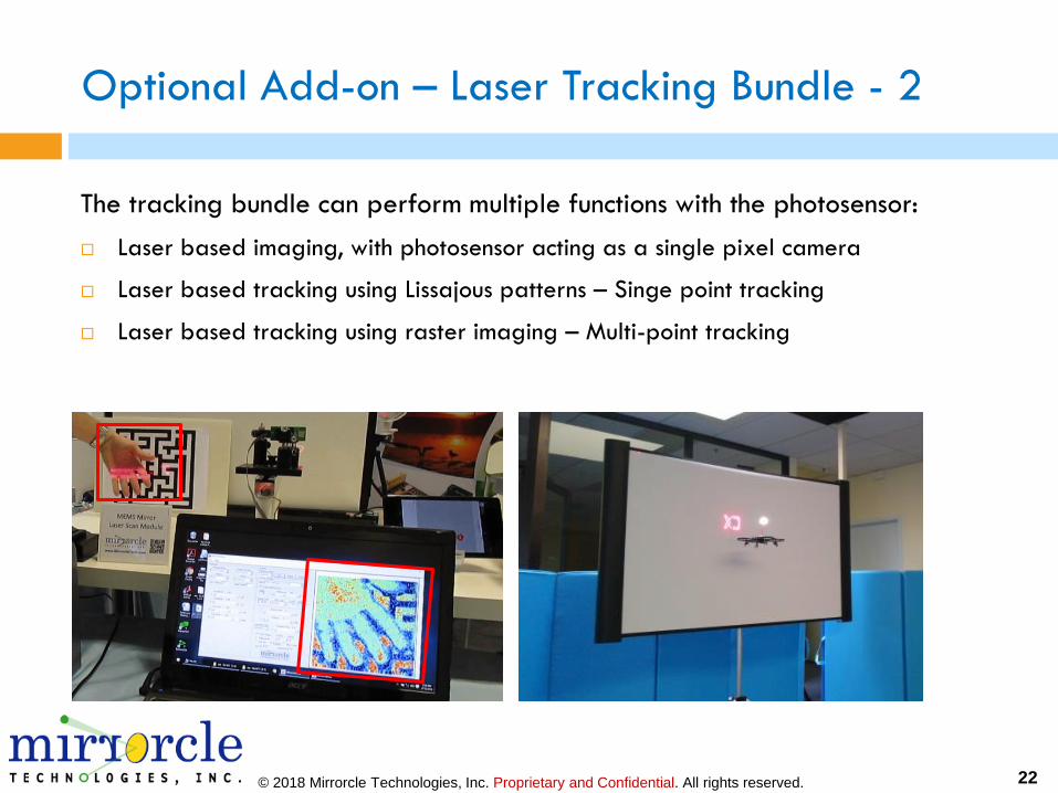
Optional Add-on – Laser Tracking Bundle - 2
The tracking bundle can perform multiple functions with the photosensor:
Laser based imaging, with photosensor acting as a single pixel camera
Laser based tracking using Lissajous patterns – Singe point tracking
Laser based tracking using raster imaging – Multi-point tracking
© 2018 Mirrorcle Technologies, Inc. Proprietary and Confidential. All rights reserved. 23
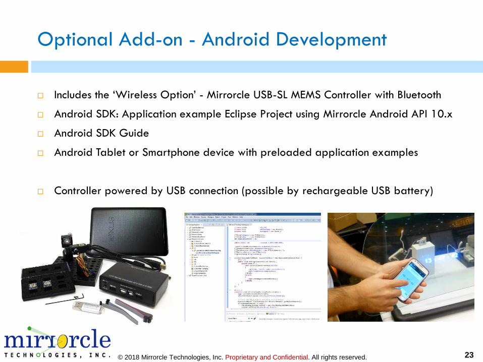
Optional Add-on - Android Development
Includes the ‘Wireless Option’ - Mirrorcle USB-SL MEMS Controller with Bluetooth
Android SDK: Application example Eclipse Project using Mirrorcle Android API 10.x
Android SDK Guide
Android Tablet or Smartphone device with preloaded application examples
Controller powered by USB connection (possible by rechargeable USB battery)

© 2018 Mirrorcle Technologies, Inc. Proprietary and Confidential. All rights reserved. 24
Optional Add-on – Linux Development
Raspberry Pi with preloaded application examples and sample code
Linux C++ SDK: Application example project using Mirrorcle C++ API 10.x from
Raspberry Pi Controller
C++ SDK Guide
Controller powered by USB connection (possible by rechargeable USB battery)

© 2018 Mirrorcle Technologies, Inc. Proprietary and Confidential. All rights reserved. 25
Optional Add-on – PSD Bundle
The PSD Bundle consists of a PSD Module, a focusable
Red Laser, and a set of Matlab scripts for use with
Mirrorcle Software Suite’s Matlab SDK for creating Look-
Up-Tables, characterizing MEMS devices Angle vs.
Vdifference responses, etc.
The PSD Module consists of a 20mm x 20mm duo-lateral
PSD (Position Sensing Device) and conditioning circuits for
powering the PSD and converting its output currents to X
and Y positions, and a CW red laser module with focusing
capability.
The entire PSD + PCB stack is enclosed in a mechanical
mount with a ½ inch diameter post for easy integration
into an optical breadboard setup.
The laser module ties into the PCB stack on the PSD for
power Mounted PSD Module
© 2018 Mirrorcle Technologies, Inc. Proprietary and Confidential. All rights reserved.
OEM MEMS Controllers
© 2018 Mirrorcle Technologies, Inc. Proprietary and Confidential. All rights reserved. 27
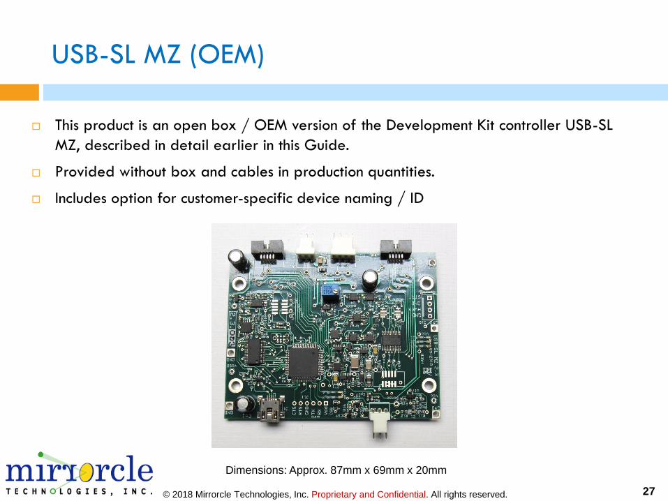
USB-SL MZ (OEM)
This product is an open box / OEM version of the Development Kit controller USB-SL
MZ, described in detail earlier in this Guide.
Provided without box and cables in production quantities.
Includes option for customer-specific device naming / ID
Dimensions: Approx. 87mm x 69mm x 20mm
© 2018 Mirrorcle Technologies, Inc. Proprietary and Confidential. All rights reserved. 28
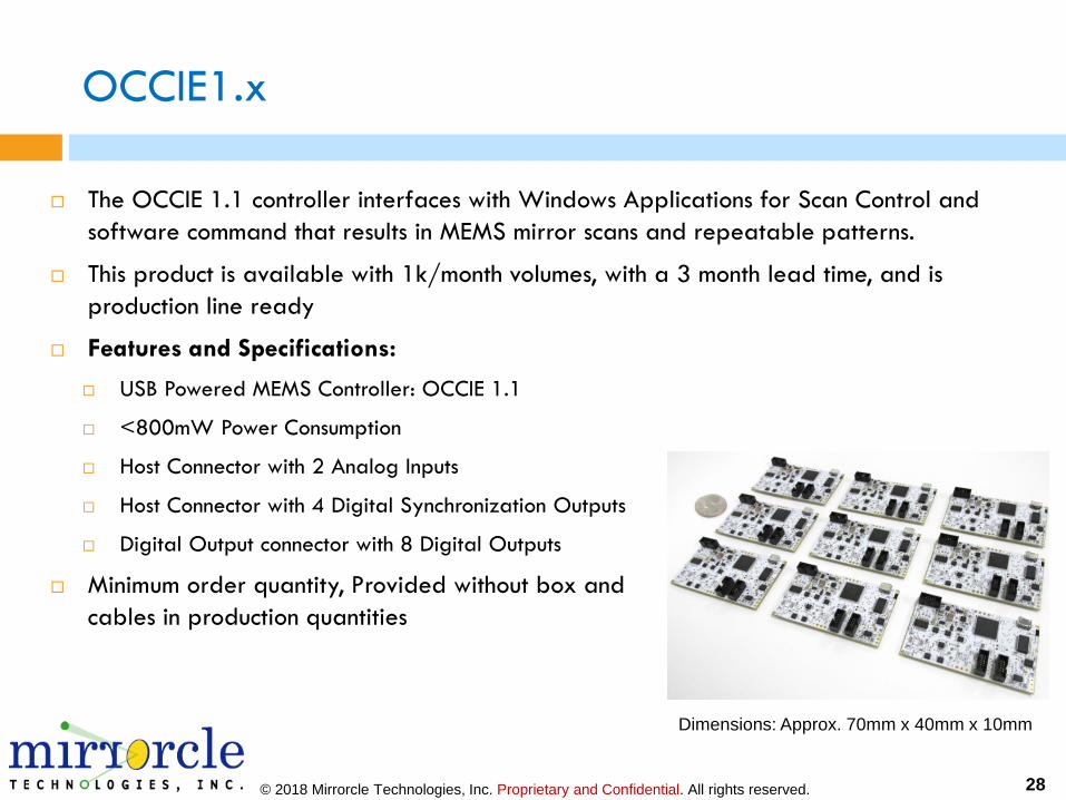
OCCIE1.x
The OCCIE 1.1 controller interfaces with Windows Applications for Scan Control and
software command that results in MEMS mirror scans and repeatable patterns.
This product is available with 1k/month volumes, with a 3 month lead time, and is
production line ready
Features and Specifications:
USB Powered MEMS Controller: OCCIE 1.1
<800mW Power Consumption
Host Connector with 2 Analog Inputs
Host Connector with 4 Digital Synchronization Outputs
Digital Output connector with 8 Digital Outputs
Minimum order quantity, Provided without box and
cables in production quantities
Dimensions: Approx. 70mm x 40mm x 10mm

© 2018 Mirrorcle Technologies, Inc. Proprietary and Confidential. All rights reserved.
OEM MEMS Drivers
© 2018 Mirrorcle Technologies, Inc. Proprietary and Confidential. All rights reserved. 30
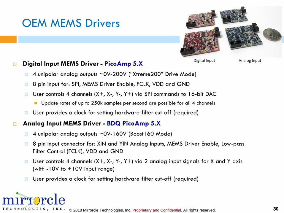
OEM MEMS Drivers
Digital Input MEMS Driver - PicoAmp 5.X
4 unipolar analog outputs ~0V-200V (“Xtreme200” Drive Mode)
8 pin input for: SPI, MEMS Driver Enable, FCLK, VDD and GND
User controls 4 channels (X+, X-, Y-, Y+) via SPI commands to 16-bit DAC
◼ Update rates of up to 250k samples per second are possible for all 4 channels
User provides a clock for setting hardware filter cut-off (required)
Analog Input MEMS Driver - BDQ PicoAmp 5.X
4 unipolar analog outputs ~0V-160V (Boost160 Mode)
8 pin input connector for: XIN and YIN Analog Inputs, MEMS Driver Enable, Low-pass
Filter Control (FCLK), VDD and GND
User controls 4 channels (X+, X-, Y-, Y+) via 2 analog input signals for X and Y axis
(with -10V to +10V input range)
User provides a clock for setting hardware filter cut-off (required)
30
Digital Input Analog Input
© 2018 Mirrorcle Technologies, Inc. Proprietary and Confidential. All rights reserved. 31
MEMS Driver 5.x Features
Low voltage supply and low power consumption (<100mW)
Four high voltage output channels (two biased differential pairs) (~0V up to 200V)
Embedded regulated DC/DC converter creates high voltage supply from the +5VDC
supply (VDD)
Four embedded Bessel low pass filters. User-provided clock sets cut-off frequency for
all four LPFs with separate control for X and Y axis.
(Optional for larger quantities) Four continuous time low pass filters.
Small form factor, approximately ½ of a credit card size: 35mm x 40mm x 9mm
Power supply monitoring with auto-shutdown
Bandwidth up to 25kHz (governed by the user-set LPFs)
Analog Input – Two analog inputs for X and Y axis drive (+/- 10V)
Digital Input – SPI digital inputs for X and Y axis drive (3VTTL)
© 2018 Mirrorcle Technologies, Inc. Proprietary and Confidential. All rights reserved. 32
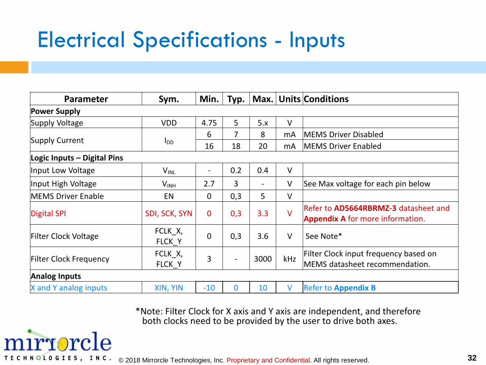
Electrical Specifications - Inputs
Parameter Sym. Min. Typ. Max. Units ConditionsPower Supply
Supply Voltage VDD 4.75 5 5.x V
Supply Current IDD6 7 8 mA MEMS Driver Disabled
16 18 20 mA MEMS Driver Enabled
Logic Inputs – Digital Pins
Input Low Voltage VINL - 0.2 0.4 V
Input High Voltage VINH 2.7 3 - V See Max voltage for each pin below
MEMS Driver Enable EN 0 0,3 5 V
Digital SPI SDI, SCK, SYN 0 0,3 3.3 VRefer to AD5664RBRMZ-3 datasheet and Appendix A for more information.
Filter Clock VoltageFCLK_X, FLCK_Y
0 0,3 3.6 V See Note*
Filter Clock FrequencyFCLK_X, FLCK_Y
3 - 3000 kHzFilter Clock input frequency based on MEMS datasheet recommendation.
Analog Inputs
X and Y analog inputs XIN, YIN -10 0 10 V Refer to Appendix B
*Note: Filter Clock for X axis and Y axis are independent, and therefore both clocks need to be provided by the user to drive both axes.
© 2018 Mirrorcle Technologies, Inc. Proprietary and Confidential. All rights reserved. 33
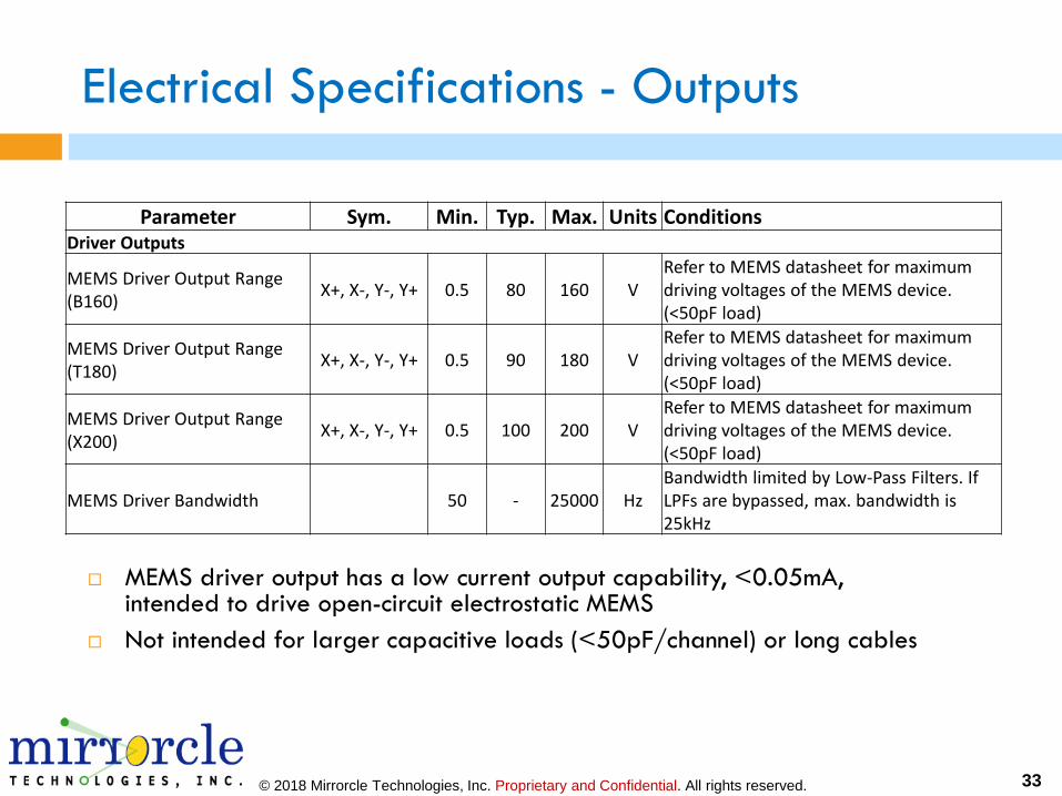
Electrical Specifications - Outputs
MEMS driver output has a low current output capability, <0.05mA, intended to drive open-circuit electrostatic MEMS
Not intended for larger capacitive loads (<50pF/channel) or long cables
Parameter Sym. Min. Typ. Max. Units ConditionsDriver Outputs
MEMS Driver Output Range (B160)
X+, X-, Y-, Y+ 0.5 80 160 VRefer to MEMS datasheet for maximum driving voltages of the MEMS device. (<50pF load)
MEMS Driver Output Range (T180)
X+, X-, Y-, Y+ 0.5 90 180 VRefer to MEMS datasheet for maximum driving voltages of the MEMS device. (<50pF load)
MEMS Driver Output Range (X200)
X+, X-, Y-, Y+ 0.5 100 200 VRefer to MEMS datasheet for maximum driving voltages of the MEMS device. (<50pF load)
MEMS Driver Bandwidth 50 - 25000 HzBandwidth limited by Low-Pass Filters. If LPFs are bypassed, max. bandwidth is 25kHz
© 2018 Mirrorcle Technologies, Inc. Proprietary and Confidential. All rights reserved. 34
Driving the Mirrors - The BDQ Principle
Bias-Differential Quad-channel (BDQ) is the proper methodology for driving
Mirrorcle MEMS Mirrors.
All four channels are biased to 80V (Vbias). This is MEMS mirror origin/rest
position.
Pairs of channels apply (biased) differential voltages from ~0V to 160V. Mirror
rotates approximately proportionally to the applied Vdifference for each axis.
Vdifference (X-axis) = HV_A – HV_B
Vdifference (Y-axis) = HV_C – HV_D
All Mirrorcle control and driving hardware should be operated in this fashion
and all Mirrorcle software supports this mode.
In the Analog Input PicoAmp, it is inherently implemented by adding a bias to
the four output channels and forcing them as differential pairs.
In the Digital Input PicoAmp this methodology should be implemented by the
user by adding a bias value to the four output channels and forcing them as
differential pairs.
34

© 2018 Mirrorcle Technologies, Inc. Proprietary and Confidential. All rights reserved. 35
Bi-directional Driving with Unipolar Outputs
HV_B is high
HV_A is low
Vdifference(X) is
negative so mirror
rotates in X- direction
HV_A is high
HV_B is low
Vdifference(X) is
positive so mirror
rotates in X+ direction
Resulting X
movement
Bi-directional driving with unipolar voltages. Direction depends on which portion of the rotator
(X+ or X-) is driven with the higher voltage. As a result each axis can move from negative
angle to positive angle from rest/normal position.
© 2018 Mirrorcle Technologies, Inc. Proprietary and Confidential. All rights reserved. 36
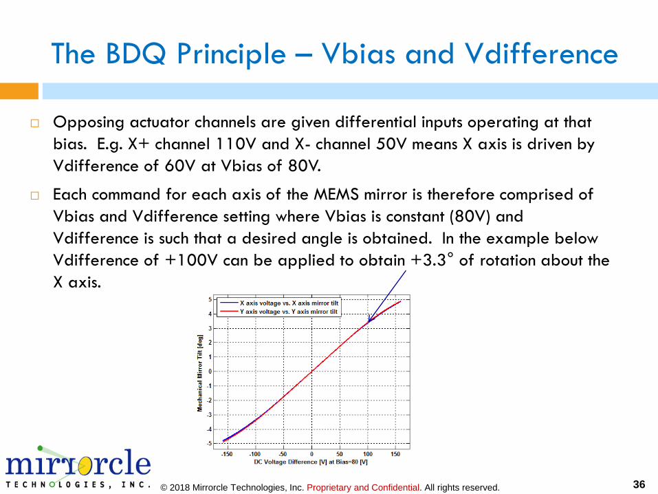
The BDQ Principle – Vbias and Vdifference
Opposing actuator channels are given differential inputs operating at that
bias. E.g. X+ channel 110V and X- channel 50V means X axis is driven by
Vdifference of 60V at Vbias of 80V.
Each command for each axis of the MEMS mirror is therefore comprised of
Vbias and Vdifference setting where Vbias is constant (80V) and
Vdifference is such that a desired angle is obtained. In the example below
Vdifference of +100V can be applied to obtain +3.3° of rotation about the
X axis.
© 2018 Mirrorcle Technologies, Inc. Proprietary and Confidential. All rights reserved. 37
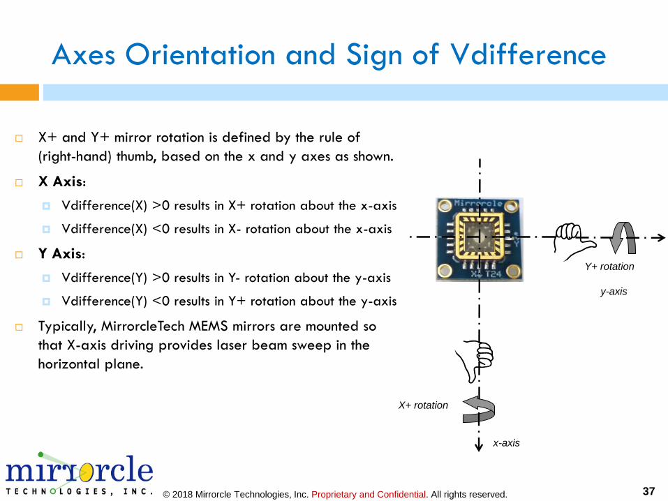
Y+ rotation
X+ rotation
Axes Orientation and Sign of Vdifference
X+ and Y+ mirror rotation is defined by the rule of
(right-hand) thumb, based on the x and y axes as shown.
X Axis:
Vdifference(X) >0 results in X+ rotation about the x-axis
Vdifference(X) <0 results in X- rotation about the x-axis
Y Axis:
Vdifference(Y) >0 results in Y- rotation about the y-axis
Vdifference(Y) <0 results in Y+ rotation about the y-axis
Typically, MirrorcleTech MEMS mirrors are mounted so
that X-axis driving provides laser beam sweep in the
horizontal plane.
x-axis
y-axis

© 2018 Mirrorcle Technologies, Inc. Proprietary and Confidential. All rights reserved. 38
Driver Connections Breakout: BRK-DRIVER 5.x
PCBA which breaks out the input connection side of both digital and analog-input MEMS
driver to easy to use terminals or test points / pins. Each pin of the 10-pin connector has
its own screw terminal, hook, and hole connection and easy to read label. Recommended
and prepared for first-time users of Mirrorcle's MEMS Drivers (Ver. 5.x). A new user
should consider purchasing this item with the first purchase of a MEMS Driver 5.x,
digital- or analog-input type.
INPUT: Screw terminals, test points, connect pins - multiple options for easy connections.
OUTPUT: 10-pin header connector (0.05", 2 rows, right angle) which can be directly
connected to MEMS Drivers (Analog and Digital) of 5.x generations.
This item is only offered with a purchase of a Mirrorcle MEMS Driver
38
Wire Terminal 5 Pin Wire Terminal 5 Pin
Wire Hooks 2 Pin Jumper and Header
10 Pin header