minus e documentation - amazon web services
TRANSCRIPT

Minus E
Documentation
Jack B. Du
April 30, 2017

Table of Contents
Preface 3
Abstract 5
The Process 7
Gallery 17
Circle 17
Black to White 18
Apple 19
Shirky’s Eye 20
Apple 21
Nicole Chan 22
WWF 23
Hand 24
Self-Portrait 25
Steve Jobs 26
Hole 27
Qian 28
WiFi 29
Wo 30
Next Step 31
Acknowledgements 32
Links 33
Web page 33
Social Media 33
1

Preface
My interest in technology can trace all the way back to my childhood, when I used a
computer for the first time at the age of six. Back then, the killer app for me, personally, is
probably Microsoft Paint, which is preinstalled in the Microsoft Windows 98 that I was
using. I loved the app and I painted everything that I can possibly imagine as a child, and
the best of all is that I can print it out, in black and white, with a dot matrix printer. Now,
after so many years, painting apps and printers have been changing and improving so
dramatically, but those old stories are still rooted in my memory, and I believe that was
when I started the journey of exploring technology and art.
My first close encounter with robot technology is in my middle school. I was so
privileged to be chosen to be part of the robot studio that was then founded. We were given
a robot kit and what we were doing was pretty preliminary, just following the instructions to
put parts together and use the code that comes with the kit. But that was still a very good
lesson for me to learn those fundamental concepts behind a robot, and the design of Minus
E is very much influenced by the robot kit that I had there, because that is where I learned
about omni wheels, which are the wheels that I used for my robot.
Fast forward to the first year of college, when I was introduced to Arduino in
Computational Media (now Interaction Lab), one of the first thing that came to my mind is to
build a robot, which was what I did for my midterm, a robot, or actually a mini car,
controlled by an IR remote.
I loved drawing and painting when I was a child, as you can see with my early
experience with computer, but I sort of quit drawing and painting when more and more
schoolworks were piled up in middle school and high school, art has been away from me
for quite a few years until my junior year in college, when I was studying away in New York
and overwhelmed by the computer science courses that I was taking in the first semester
there, I decided to take a break from computer science, and try something that are
non-major related. Naturally, I enrolled in a drawing class, and that class brought up all my
good memories I had with drawing when I was kid and the next semester, when I went to
Abu Dhabi, I decided to take four visual art classes, and I loved it. That was also when I
wrote my IMA capstone proposal and planned to make a drawing robot.
I know it has been quite a long story, but I almost cannot talk about this project
without telling the story, because these experiences have really contributed to the decisions
2

I make, which ultimately contributed to the making of this project. And I sincerely hope you
will enjoy reading about this project as well as the final results.
April 30, 2017
3

Abstract
This project is a robotic system that collaborates with me to produce large scale
drawings. The system consists of two major parts, a roomba-like mobile robot and a
webcam. The robot is powered by a Raspberry Pi, a single-board computer developed by
Raspberry Pi Foundation, that runs a server-side program to handle the movements of the
robot. A GrovePi+ is attached to the Raspberry Pi, which is connected to two motor drivers,
and those two motor drivers then control the four DC motors to rotate in either direction at
a given speed. Four omni wheels are used to make it possible for the robot to have free
movement to any direction without rotating itself. The motor drivers and the Raspberry Pi
are powered with a lithium-ion battery at different voltages. An acrylic chassis designed to
combine all these parts together in one place, and the center of which is a series of holes
that hold the marker in place when the robot draws. Moreover, there is a red ball and a blue
ball that is placed on top of the robot. One the other side, the webcam is placed on the
ceiling of the room, which is plugged into a computer that runs the client-side program.
4

For each drawing, the canvas is first cut properly and then placed right below the
webcam, where the webcam can capture the full canvas, and the robot is then placed at a
desired starting point with a permanent marker at the center. On the computer that is
connected to the webcam, an image of reference will be set as an input to the client
program, along with other parameters such canvas size, output resolution, color depth, etc.
Once the program is running, it will first convert the reference image to the output
resolution, for instance, 16 pixels by 16 pixels, then it calculates where each pixel should be
mapped on the physical canvas and reads the value (darkness) of each pixel, generating a
list of coordinates the robot need to go as well as a list of darkness corresponding to each
coordinate. The program then reads each frame taken by the webcam, analyzes it. By
tracking the blue and red ball on the robot, the program is able to position the robot and
then sends command, including the speed and direction of each motor, to the Raspberry Pi
over WiFi, and the Raspberry Pi changes the speed and direction of each motor based on
the received command. The client program will go over the whole list of coordinates, by first
sending the robot to the specified coordinate, performing proper amount of drawing based
on its darkness and then going to the next one until the end.
5

The Process
The very initial idea was to build a mobile robot that holds a human drawing
instrument and moves around on the paper, which is laid on the ground. I was trying to
avoid abstract work at the first place because, one, I don’t have a good reason to do
abstraction, two, doing abstraction for the first type of work for an artist, to me, is kind of
cheating, it is not absolutely true, but what I’m saying is that if the robot just moves
randomly and draws random stuff, I wouldn’t be satisfied, and I won’t consider the robot to
be a good artist. Yes, at that stage, I was thinking about making an artist and to question
whether or not robot can produce art independently. Some other ideas includes the robot
first moving around with its camera, which serves as an eye, to observe the world and take
multiple pictures then decide which picture or pictures to draw, cropping them and
potentially mix them then start drawing based on those references the robot picks on its
own. I was even thinking that the robot may take more pictures as it draws and blend more
pictures in the final drawing work. At that time, I was thinking about a scale that’s as large a
room and I planned to use ultrasonic rangers for localizations. However, I realized ultrasonic
rangers are not a good choice for localization and I did not figure out a way to localize the
robot, which is a headache for many different mobile robot development.
I was almost losing hope as the robot does not even know where it is. One day, I
came up with an idea that I believed is stronger than the original idea, which is to let robot
draws one pixel by another pixel. First, a grid system is very common in drawing and
painting process, where artists put a grid on the reference image as well as a grid on the
canvas, by doing that, the artist can draw grid by grid, without worrying about the overall
scale and proportional, because as long as you can create a nice drawing within each tile,
the finally work will be unified and in the right proportional. But this robot is more inspired
by the American artist Chuck Close, who uses a grid system, but he does not paint details
within one tile, what he does instead is to fill the whole tile with different layers and shapes
of color, which almost looks like an individual abstract painting in one tile, but the average
or optical color of that tile will resemble the reference image so that when all tiles are
finished, the overall painting will resemble the reference image. When viewed far away, his
paintings are almost photorealistic. One thing I have to mention about Close is that a stroke
left him paralyzed so that he is not able to hold brushes with precisions at all, but he never
stops producing more paintings and one cannot tell the difference between his work done
before and after the stroke. The moral of the story, to me, is that such a painting technique
6
does not require too much precision, which is exactly the constrains that my robot has. But
of course, it cannot navigate at all at the time, so my plan was, in the worst scenario, I will
give my robot one piece of paper, and the robot should be able to detect the edges of the
paper with the help of black lines and line finders, so that the robot can fill up one piece of
paper with the darkness of corresponding pixel in the reference image and then works on
the next one when I manually replace the paper. When I had this idea, I wanted to first test
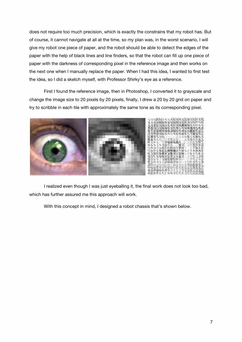
the idea, so I did a sketch myself, with Professor Shirky’s eye as a reference.
First I found the reference image, then in Photoshop, I converted it to grayscale and
change the image size to 20 pixels by 20 pixels, finally, I drew a 20 by 20 grid on paper and
try to scribble in each tile with approximately the same tone as its corresponding pixel.
I realized even though I was just eyeballing it, the final work does not look too bad,
which has further assured me this approach will work.
With this concept in mind, I designed a robot chassis that’s shown below.
7

Then I used a laser cutter to cut it on a black acrylic board:
8

When they are put together with all other parts, I got:
At this point, I was still hoping to use line finders to detect the edges and potentially
navigate through a grid of black lines. At the same time, I was also looking for Python
libraries that can track a marker. Surprisingly, none of the libraries I tried work well. So I
decided to go for color tracking. Following along this post, I figured out how to track a ball with specific color, then, by tracking two balls, it can further calculate the rotation of the
robot. After testing all different colors, I eventually chose blue and red, which, in my tests,
appeared to be the most accurate.
I was using a Raspberry Pi and its camera module to track the robot, it worked, but
the Raspberry Pi is only able to process around 2 frames per second, which is way too
slow. So I decided to use a laptop and a webcam, within a long USB cable so that the
webcam can be placed on the ceiling. With this configuration, it gives me around 10 frames
per second, which isn’t fast at all, but sufficient for this project. The program was then able
to track the position and rotation of the robot by tracking those two balls, but in order to
make it draw, I need to do transform between two coordinate systems, the system of the
9

camera, and the system of the robot itself, which is further explained in the comments of
the source code. It took me quite some time to figure out the math, but it really worth it.
When I coded that part up, I did some tests on moving in straight lines, and I found
a few bugs along the way, which I later fixed. But still, the robot is not able to go very
straight (see above), which is understandable because the motors are regular DC motors
and they are not accurate. However, the destination is fairly accurate, which means the
robot should be able to go to a specified cell, move around that particular spot and then go
to the next cell. With the hope that it will work, I switched from whiteboard to paper, and it
was 28 sheets of A3 paper. The result can be seen below. If I don’t tell you the robot is
trying to draw Professor Shirky’s eye, you would probably never tell. As you can see,
there’s an area that is completely black, which is because the robot got stuck there. But the
interesting thing is, if I stop the robot and start it again at where it is left, the robot seems to
work fine, but it got stuck again after a while, so it must have something to do with my
code. I also realized, from the console, the frame per second decreases gradually which
means somehow the program runs slower as it goes.
It turned out the program works fine when I removed the code for recording video
from the webcam, so that’s what slows the program down, but what about the recording? I
still want it to record video for my documentation, so eventually, I decided to make the
program take a picture after the robot finishes one cell, which can be later edited in
Premiere to create a timelapse.
10

At the same time, I realized it’s so inefficient to debug with the real robot drawing on
paper, it costs money and it takes time. So I wrote a quick and dirty simulation for it. I call it
quick and dirty, because it doesn’t do exactly what the robot do, but it can give an idea of
what the final drawing will look like. Here’s what the simulation did for the same reference
image.
11

So it starts to look like something, that means my code should work fine with the
real robot and here I did the test with very low contrast so as to be fast.
If you look closely, you can probably see the similarity between this one and the
simulation, but yes, it is still too light, but I was excited that it starts working. So I increased
the contrast parameter, and had the result below.
12

Although it got stuck again (for a different reason, which I fixed) and it took two
markers (so I had to stop the robot and replace the marker), it seems to work, at least
almost as good as the simulation can do. I also did a test by separating the reference image
into four pieces.
In order to avoid the marker getting dry, I had only 100 pixels on each piece,
because of which, the pixels are very isolated, which definitely provides a surprisingly
interesting style, but the final result is still not so recognizable as an eye. Finally, I think the
robot should be good at high contrast reference images, so I decided to let it draw a circle,
and the result is definitely satisfying.
13

At the same time, both to help me debug and to help visitors understand how the
grid works, I added the grid to the monitor.
Now I should probably explain a bit more about how the algorithm works. We
already knew that the client program keeps two lists, a list of coordinates the robot needs
to go, and a list of darkness values corresponding to each coordinate. When the robot
arrives at the cell with specified coordinate, the robot will starts to fill up this cell. The way it
fills is to move to a random direction, whenever the robot moves, the value will decrement
by one, and whenever the robot goes outside the cell, the client program will ask it to go
back and then move to random direction until the value for this cell meets zero, which
means enough among of lines are drawn in this one cell and moves to the next one. I know
people will question the accuracy of this algorithms, but as we can see, it is accurate
enough to draw high contrast images, and my objective of this project is not to produce an
accurate drawing machine like so many other projects have achieved, because when it is
accurate, it is more like a printer to me.
14

Later on, I started to draw on canvas and I explored some very primitive color
drawing, because the three colors the robot used are the three colors in the reference
image. And I actually manually created three separate reference images for each color, and
it basically made three drawings layer by layer on the same canvas.
15

Gallery
This is a collection of drawings the robot has created so far.
Circle
Ink on paper, 176 x 176 cm (5.8 x 5.8 ft).
16

Black to White
Ink on paper, 176 x 176 cm (5.8 x 5.8 ft).
17

Apple
Ink on paper, 176 x 176 cm (5.8 x 5.8 ft).
18

Shirky’s Eye
Ink on paper, 352 x 352 cm (11.5 x 11.5 ft).
19

Apple
Ink on paper, 176 x 176 cm (5.8 x 5.8 ft).
20

Nicole Chan
Ink on paper, 176 x 176 cm (5.8 x 5.8 ft).
21

WWF
Ink on paper, 176 x 176 cm (5.8 x 5.8 ft).
22

Hand
Ink on canvas, 176 x 176 cm (5.8 x 5.8 ft).
23

Self-Portrait
Ink on canvas, 176 x 176 cm (5.8 x 5.8 ft).
24

Steve Jobs
Ink on canvas, 250 x 176 cm (8.2 x 5.8 ft).
25

Hole
Ink on canvas, 176 x 176 cm (5.8 x 5.8 ft).
26

Qian
Ink on canvas, 176 x 176 cm (5.8 x 5.8 ft).
27

WiFi
Ink on canvas, 176 x 176 cm (5.8 x 5.8 ft).
28

Wo
Ink on canvas, 176 x 176 cm (5.8 x 5.8 ft).
29

Next Step
There are a few different things I want to further explore:
● Different Routes
For now, the robot goes zigzag and one row after the other, one interesting route
could be a spiral route, where the robot finishes the outmost cells and then goes to
the inner cells, especially with a reference image that is in spiral or circular fashion.
Further, it can goes on a more dynamic route, or even attempts a style that is not
based on grid.
● Stop Motion Animation
As Professor Belanger has suggested, one interesting experiment is to draw a few
frames of an animation and make a gif or very short animation.
● Generative Art
The drawings the robot creates now are all based on an reference image, in order to
be creative and create more original work, I can apply some generative algorithms to
produce a route/path that isn’t based on a reference image nor a grid.
● Color Drawing
The current attempt for color drawing is primitive, because it uses the three colors
from the reference, I’d like to try color drawings with CMYK to see how it will go.
That just requires me to get proper markers and separate the images into different
channels.
● Different Media
The robot draws only with regular permanent markers, even the attempt for
oil-based markers have failed. I want to explore other media, especially paints. I may
try a dripping method with acrylic paints premixed.
30

Acknowledgements
Special thanks to
Prof. Rodolfo Cossovich, for constantly providing feedback and technical help
Prof. Anna Greenspan, for teaching my session of capstone studio, and providing helpful feedback and supervision
Prof. Matthew Belanger , for having several talks with me on the project
Prof. Clay Shirky, for allowing me to use his profile picture as well as his worthy comments
Prof. Roopa Vasudevan, for signing my budget proposal
Prof. Christian Grewell, for his comments as well as lending me his long USB cable and webcam
Marcela Godoy and Jiwon Shin, for helping me with laser cutting
All other IMA faculty and classmates who have provided suggestions, inspirations, comments, questions, or even just showed their interests in my project.
Raspberry Pi Foundation, OpenCV and Seeed Studio
31

Links
Web page
Official Page: minusetheartbot.github.io
GitHub: github.com/minusetheartbot
WordPress: jackbdu.wordpress.com/category/ima-capstone/
Social Media
Instagram: @minusetheartbot
Twitter: @minusetheartbot
32