minn kota motors boating & marine installation instructions
TRANSCRIPT

WARRANTY ON MINN KOTA FRESHWATER TROLLING MOTORSJohnson Outdoors Marine Electronics, Inc. (“JOME”) extends the following limited warranty to the original retail purchaser only. Warranty coverage is nottransferable.
MINN KOTA LIMITED TWO-YEAR WARRANTY ON THE ENTIRE PRODUCT
JOME warrants to the original retail purchaser only that the purchaser’s new Minn Kota freshwater trolling motor will be materially free from defects in materialsand workmanship appearing within two (2) years after the date of purchase. JOME will (at its option) either repair or replace, free of charge, any parts found byJOME to be defective during the term of this warranty. Such repair, or replacement shall be the sole and exclusive liability of JOME and the sole and exclusiveremedy of the purchaser for breach of this warranty.
MINN KOTA LIMITED LIFETIME WARRANTY ON COMPOSITE SHAFT
JOME warrants to the original retail purchaser only that the composite shaft of the purchaser’s Minn Kota trolling motor will be materially free from defects inmaterials and workmanship appearing within the original purchaser’s lifetime. JOME will provide a new composite shaft, free of charge, to replace any compositeshaft found by JOME to be defective during the term of this warranty. Providing a new composite shaft shall be the sole and exclusive liability of JOME and thesole and exclusive remedy of the purchaser for breach of this warranty; and purchaser shall be responsible for installing, or for the cost of labor toinstall, any new composite shaft provided by JOME.
EXCLUSIONS & LIMITATIONS
This limited warranty does not apply to products that have been used in saltwater or brackish water, commercially or for rental purposes. This limited warrantydoes not cover normal wear and tear, blemishes that do not affect the operation of the product, or damage caused by accidents, abuse, alteration, modification,shipping damages, acts of God, negligence of the user or misuse, improper or insufficient care or maintenance. DAMAGE CAUSED BY THE USE OFOTHER REPLACEMENT PARTS NOT MEETING THE DESIGN SPECIFICATIONS OF THE ORIGINAL PARTS WILL NOT BE COVERED BYTHIS LIMITED WARRANTY. The cost of normal maintenance or replacement parts which are not in breach of the limited warranty are the responsibilityof the purchaser. Prior to using products, the purchaser shall determine the suitability of the products for the intended use and assumes all related risk andliability. Any assistance JOME provides to or procures for the purchaser outside the terms, limitations or exclusions of this limited warranty will not constitutea waiver of the terms, limitations or exclusions, nor will such assistance extend or revive the warranty. JOME will not reimburse the purchaser for any expensesincurred by the purchaser in repairing, correcting or replacing any defective products or parts, except those incurred with JOME’s prior written permission.JOME’S AGGREGATE LIABILITY WITH RESPECT TO COVERED PRODUCTS IS LIMITED TO AN AMOUNT EQUAL TO THE PURCHASER’SORIGINAL PURCHASE PRICE PAID FOR SUCH PRODUCT.
MINN KOTA SERVICE INFORMATION
To obtain warranty service in the U.S., the product believed to be defective, and proof of original purchase (including the date of purchase), must be presentedto a Minn Kota Authorized Service Center or to Minn Kota’s factory service center in Mankato, MN. Any charges incurred for service calls, transportation orshipping/freight to/from the Minn Kota Authorized Service Center or factory, labor to haul out, remove, re-install or re-rig products removed for warranty service,or any other similar items are the sole and exclusive responsibility of the purchaser. Products purchased outside of the U.S. must be returned prepaid withproof of purchase (including the date of purchase and serial number) to any Authorized Minn Kota Service Center in the country of purchase. Warranty servicecan be arranged by contacting a Minn Kota Authorized Service Center or by contacting the factory at 1-800-227-6433 or email [email protected] repaired or replaced will be warranted for the remainder of the original warranty period [or for 90 days from the date of repairor replacement, whichever is longer]. For any product that is returned for warranty service that JOME finds to be not covered by or notin breach of this limited warranty, there will be a billing for services rendered at the prevailing posted labor rate and for a minimum of atleast one hour.
NOTE: Do not return your Minn Kota product to your retailer. Your retailer is not authorized to repair or replace products.
THERE ARE NO EXPRESS WARRANTIES OTHER THAN THESE LIMITED WARRANTIES. IN NO EVENT SHALL ANY IMPLIEDWARRANTIES INCLUDING ANY IMPLIED WARRANTIES OF MERCHANTABILITY OR FITNESS FOR PARTICULAR PURPOSE, EXTENDBEYOND THE DURATION OF THE RELEVANT EXPRESS LIMITED WARRANTY. IN NO EVENT SHALL JOME BE LIABLE FOR PUNITIVE,INDIRECT, INCIDENTAL, CONSEQUENTIAL OR SPECIAL DAMAGES. Without limiting the foregoing, JOME assumes no responsibility forloss of use of product, loss of time, inconvenience or other damage.
Some states do not allow limitations on how long an implied warranty lasts or the exclusion or limitation of incidental or consequential damages, so the abovelimitations and/or exclusions may not apply to you. This warranty gives you specific legal rights and you may also have other legal rights which vary from stateto state.
FEATURES
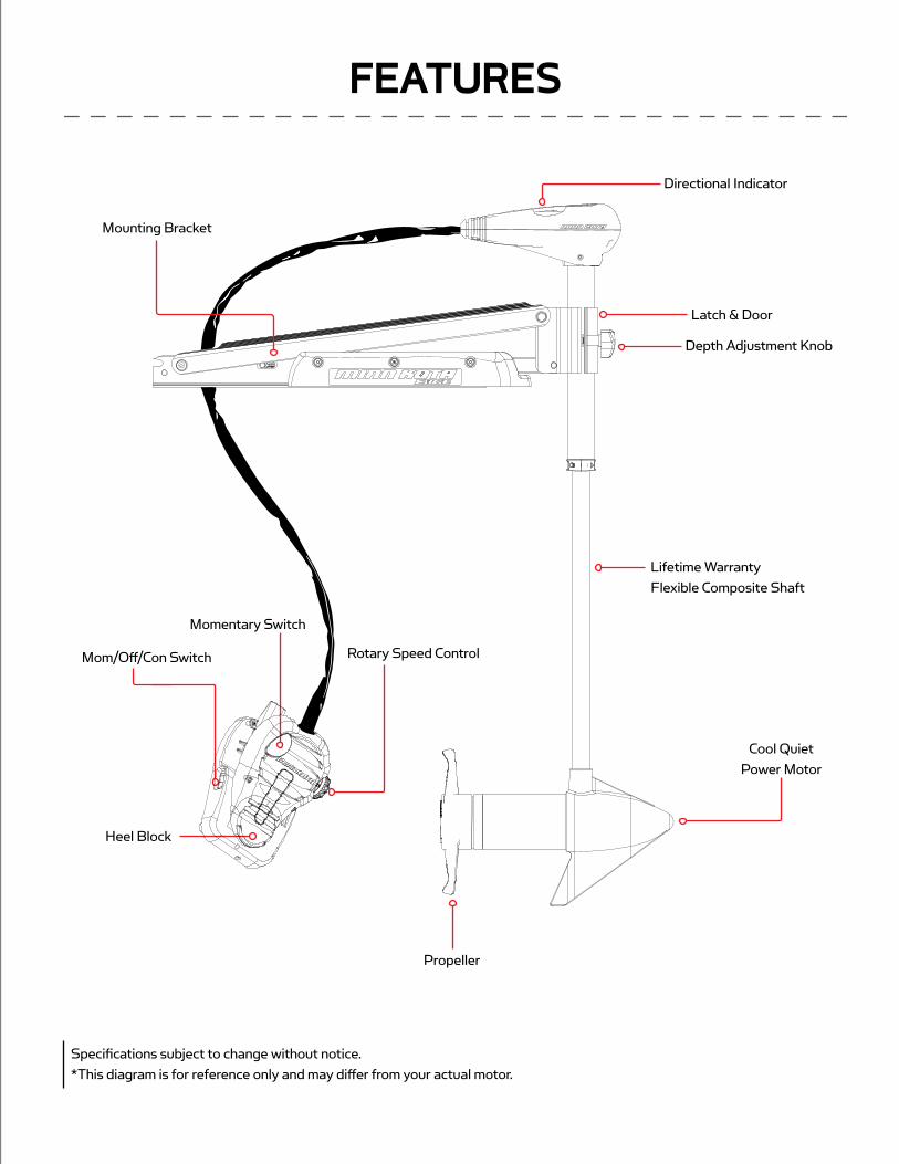
Specifications subject to change without notice.*This diagram is for reference only and may differ from your actual motor.
Latch & Door
Depth Adjustment Knob
Directional Indicator
Mounting Bracket
Lifetime Warranty Flexible Composite Shaft
Propeller
Momentary Switch
Mom/Off/Con Switch
Heel Block
Rotary Speed Control
Cool Quiet Power Motor

TOOLS AND RESOURCES REQUIRED:
• Phillips Screw Driver
• Drill
• 9/32” Drill Bit
• 7/16” Box End Wrench
• A second person to help with the installation
1. Before you proceed, determine the desired mounting location for the motor. It is recommended that the motor be mounted asclose to the center line of the boat as possible as seen below.CAUTION: Make sure the motor is mounted on a level surface and is not connected to a power source.
2. Verify the area under the chosen mounting location is clear and safe to drill through.
3. Place the motor on top of the desired mounting location while it is in the stowed position (for stow and deploy instructions,see "Stowing and Deploying the Motor" on p. 11).
4. Verify the motor rest is positioned far enough beyond the edge of the boat so that the motor clears all obstructions whiledeploying and stowing the motor.
MOUNT INSTALLATION

5. Deploy the motor and remove the motor assembly from the mount by loosening the Steering Tension Knob and opening thedoor.WARNING: When raising or lowering motor, keep fi ngers clear of all hinge and pivot points and all moving parts.
6. Position the mount again in the stowed position.
7. Temporarily remove the Phillips screws that fasten the motor rest to the mounting bracket and remove the motor rest toexpose the motor mounting hole pattern.
8. Determine the mounting hole pattern you wish to use from the illustration to the right. Using the mounting holes in the mount as your template, mark the top deckof the boat with a pencil or an erasable marker.
9. Remove the mount from the deck of the boat and drill the holes that you marked in the previous step using a 9/32” drill bit and drill. Be careful not to damage any wiring or critical features that may exist under the surface you are drilling through.
10. Place the mount on the deck of the boat again and verify the hold down strap ispositioned 15 ¾” from the front of the bow mount as shown in the diagram.
11. Fasten the mount to the deck of the boat using the supplied ¼” – 20 X 2” bolts,washers and nuts. Tighten the stainless mount hardware securely but slowly to the deck of the boat using a 7/16” box end wrench. Tightening the stainless hardware too fast may result in galling and or seizing of the bolts and nuts.
12. Reinstall the motor rest using the six original ¼” Phillips screws.
13. Reinstall the motor assembly into the mount and securely tighten the steeringtension knob.
15 3/4“
Motor Rest
MOUNT INSTALLATION
Depth Adjustment Knob
Motor Assembly

BOAT RIGGING & PRODUCT INSTALLATIONFor safety and compliance reasons, we recommend that you follow American Boat and Yacht Council (ABYC) standards when rigging your boat. Altering boat wiring should be completed by a qualifi ed marine technician. The following specifi cations are for general guidelines only:CAUTION: These guidelines apply to general rigging to support your Minn Kota motor. Powering multiple motors or additional electrical devices from the same power circuit may impact the recommended conductor gauge and circuit breaker size. If you are using wire longer than that provided with your unit, follow the conductor gauge and circuit breaker sizing table below. If your wire extension length is more than 25 feet, we recommend that you contact a qualifi ed marine technician.An over-current protection device (circuit breaker or fuse) must be used. Coast Guard requirements dictate that each ungrounded current-carrying conductor must be protected by a manually reset, trip-free circuit breaker or fuse. The type (voltage and current rating) of the fuse or circuit breaker must be sized accordingly to the trolling motor used. The table below gives recommended guidelines for circuit breaker sizing. Reference: United States Code of Federal Regulations: 33 CFR 183 – Boats and Associated EquipmentABYC E-11: AC and DC Electrical Systems on Boats
CONDUCTOR GAUGE AND CIRCUIT BREAKER SIZING TABLE
Motor Thrust / Model
Max Amp Draw Circuit BreakerWire Extension Length *
5 feet 10 feet 15 feet 20 feet 25 feet
30 lb. 3050 Amp @ 12 VDC
10 AWG 10 AWG 8 AWG 6 AWG 4 AWG
40 lb., 45 lb. 42 10 AWG 8 AWG 6 AWG 4 AWG 4 AWG
50 lb., 55 lb. 50 60 Amp @ 12 VDC 8 AWG 6 AWG 4 AWG 4 AWG 2 AWG
70 lb. 42 50 Amp @ 24 VDC 10 AWG 10 AWG 8 AWG 8 AWG 6 AWG
80 lb. 56 60 Amp @ 24 VDC 8 AWG 8 AWG 8 AWG 6 AWG 6 AWG
101 lb. 46 50 Amp @ 36 VDC 8 AWG 8 AWG 8 AWG 8 AWG 8 AWG
Engine Mount 101 50 60 Amp @ 36 VDC 8 AWG 6 AWG 4 AWG 4 AWG 2 AWG
112 lb. 52 60 Amp @ 36 VDC 8 AWG 8 AWG 8 AWG 8 AWG 8 AWG
Engine Mount 160 116 (2) x 60 Amp @ 24 VDC 2 AWG 2 AWG 2 AWG 2 AWG 2 AWG
E-Drive 40 50 Amp @ 48 VDC 10 AWG 10 AWG 10 AWG 10 AWG 10 AWG
This conductor and circuit breaker sizing table is only valid for the following assumptions:1. No more than 3 conductors are bundled together inside of a sheath or conduit outside of engine spaces.2. Each conductor has 105° C temp rated insulation.3. No more than 5% voltage drop allowed at full motor power based on published product power requirements.
*Wire Extension Length refers to the distance from the batteries to the trolling motor leads.
BATTERY WIRING & INSTALLATION

BOAT RIGGING & PRODUCT INSTALLATIONFor safety and compliance reasons, we recommend that you follow American Boat and Yacht Council (ABYC) standards whenrigging your boat. Altering boat wiring should be completed by a qualified marine technician. The following specifications are forgeneral guidelines only:CAUTION: These guidelines apply to general rigging to support your Minn Kota motor. Powering multiple motors or additionalelectrical devices from the same power circuit may impact the recommended conductor gauge and circuit breaker size. If you areusing wire longer than that provided with your unit, follow the conductor gauge and circuit breaker sizing table below. If your wireextension length is more than 25 feet, we recommend that you contact a qualified marine technician.An over-current protection device (circuit breaker or fuse) must be used. Coast Guard requirements dictate thateach ungrounded current-carrying conductor must be protected by a manually reset, trip-free circuit breaker or fuse. The type(voltage and current rating) of the fuse or circuit breaker must be sized accordingly to the trolling motor used. The table below givesrecommended guidelines for circuit breaker sizing.Reference:United States Code of Federal Regulations: 33 CFR 183 – Boats and Associated EquipmentABYC E-11: AC and DC Electrical Systems on Boats
CONDUCTOR GAUGE AND CIRCUIT BREAKER SIZING TABLE
Motor Thrust /Model
Max Amp Draw Circuit BreakerWire Extension Length *
5 feet 10 feet 15 feet 20 feet 25 feet
30 lb. 3050 Amp @ 12 VDC
10 AWG 10 AWG 8 AWG 6 AWG 4 AWG
40 lb., 45 lb. 42 10 AWG 8 AWG 6 AWG 4 AWG 4 AWG
50 lb., 55 lb. 50 60 Amp @ 12 VDC 8 AWG 6 AWG 4 AWG 4 AWG 2 AWG
70 lb. 42 50 Amp @ 24 VDC 10 AWG 10 AWG 8 AWG 8 AWG 6 AWG
80 lb. 56 60 Amp @ 24 VDC 8 AWG 8 AWG 8 AWG 6 AWG 6 AWG
101 lb. 46 50 Amp @ 36 VDC 8 AWG 8 AWG 8 AWG 8 AWG 8 AWG
Engine Mount 101 50 60 Amp @ 36 VDC 8 AWG 6 AWG 4 AWG 4 AWG 2 AWG
112 lb. 52 60 Amp @ 36 VDC 8 AWG 8 AWG 8 AWG 8 AWG 8 AWG
Engine Mount 160 116 (2) x 60 Amp @ 24 VDC 2 AWG 2 AWG 2 AWG 2 AWG 2 AWG
E-Drive 40 50 Amp @ 48 VDC 10 AWG 10 AWG 10 AWG 10 AWG 10 AWG
This conductor and circuit breaker sizing table is only valid for the following assumptions:1. No more than 3 conductors are bundled together inside of a sheath or conduit outside of engine spaces.2. Each conductor has 105° C temp rated insulation.3. No more than 5% voltage drop allowed at full motor power based on published product power requirements.
*Wire Extension Length refers to the distance from the batteries to the trolling motor leads.
CONNECTING THE BATTERIES12 VOLT SYSTEMS:
1. Make sure that the motor is switched off (speed selector on “OFF” or “0”).
2. Connect positive ( + ) red lead to positive ( + ) battery terminal.
3. Connect negative ( – ) black lead to negative ( – ) battery terminal.
4. For safety reasons do not switch the motor on until the propeller is in the water.
CAUTION:For safety reasons, disconnect the motor from the battery/batteries when the motor is not in use or while the battery/batteries are being charged.
SELECTING THE CORRECT BATTERIESThe motor will operate with any lead acid, deep cycle marine 12 volt battery/batteries. For best results, use a deep cycle, marine battery with at least a 105 ampere hour rating. Maintain battery at full charge. Proper care will ensure having battery power when you need it, and will signifi cantly improve the battery life. Failure to recharge lead-acid batteries (within 12-24 hours) is the leading cause of premature battery failure. Use a multi-stage charger to avoid overcharging. We off er a wide selection of chargers to fi t your charging needs. If you are using a crank battery to start a gasoline outboard, we recommend that you use a separate deep cycle marine battery/batteries for your Minn Kota trolling motor.
Advice Regarding Batteries:
• Never connect the (+) and the (–) terminals of the battery together. Take care that no metal object can fall onto the battery andshort the terminals. This would immediately lead to a short and extreme fi re danger.
• It is highly recommended that a circuit breaker or fuse be used with this trolling motor. Refer to “Conductor Gauge and Circuit Breaker Sizing Table” in the previous section to fi nd the appropriate circuit breaker or fuse for your motor. For motors requiringa 60-amp breaker, the Minn Kota MKR-19 60-amp circuit breaker is recommended.
CONNECTING THE BATTERIES IN SERIES(IF REQUIRED FOR YOUR MOTOR)24 VOLT SYSTEMS:
1. Make sure that the motor is switched off (speed selector on “0”).
2. Two 12 volt batteries are required.
3. The batteries must be wired in series, only as directed in wiringdiagram, to provide 24 volts.
a. Connect a connector cable to the positive ( + ) terminal ofbattery 1 and to the negative ( – ) terminal of battery 2.
b. Connect positive ( + ) red lead to positive ( + ) terminal on battery 2.
c. Connect negative ( – ) black lead to negative ( – ) terminal of battery 1.
4. For safety reasons do not switch the motor on until the propeller is in the water. If installing a leadwire plug, observe properpolarity and follow instructions in your boat owner’s manual. See wiring diagram on following pages.
CAUTION
• For safety reasons, disconnect the motor from the battery or batteries when the motor is not in use or whilethe battery/batteries are being charged.
• Improper wiring of 24/36 volt systems could cause battery explosion!
• Keep leadwire wing nut connection tight and solid to battery terminals.
• Locate battery in a ventilated compartment.
To trolling motor negative
24 Volt Connection
Battery #1 (Low Side)
Neg - Neg -Pos + Pos +
Battery #2 (High Side)
+24 Volts to trolling motor positive (or circuit breaker)
24 Volt Series Connection
BATTERY WIRING & INSTALLATION

MOTOR WIRING DIAGRAM
w
Y
AB R +MOT0R
BATTERY 1
BATTERY 1 BATTERY 2
MOM/OFF/CON SWITCH
BLA
CK
/BLU
E
RE
D+
YE
LLO
W
WH
ITE
BLACK-
FIVE SPEED SWITCH RED+
BLA
CK-
RED+
TERMINAL BLOCK
MOMENTARY SWITCHBLACK/WHITE
12v
24v
NOTE: This is a universal, multi-voltage diagram. Double-check your motor's voltage for proper connections. Over-Current Protection Devices not shown in this illustration.
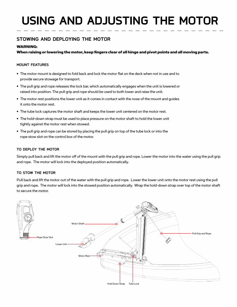
STOWING AND DEPLOYING THE MOTORWARNING: When raising or lowering the motor, keep fi ngers clear of all hinge and pivot points and all moving parts.
MOUNT FEATURES
• The motor mount is designed to fold back and lock the motor fl at on the deck when not in use and toprovide secure stowage for transport.
• The pull grip and rope releases the lock bar, which automatically engages when the unit is lowered orraised into position. The pull grip and rope should be used to both lower and raise the unit.
• The motor rest positions the lower unit as it comes in contact with the nose of the mount and guidesit onto the motor rest.
• The tube lock captures the motor shaft and keeps the lower unit centered on the motor rest.
• The hold-down strap must be used to place pressure on the motor shaft to hold the lower unittightly against the motor rest when stowed.
• The pull grip and rope can be stored by placing the pull grip on top of the tube lock or into therope stow slot on the control box of the motor.
TO DEPLOY THE MOTOR
Simply pull back and lift the motor off of the mount with the pull grip and rope. Lower the motor into the water using the pull grip and rope. The motor will lock into the deployed position automatically.
TO STOW THE MOTOR
Pull back and lift the motor out of the water with the pull grip and rope. Lower the lower unit onto the motor rest using the pull grip and rope. The motor will lock into the stowed position automatically. Wrap the hold-down strap over top of the motor shaft to secure the motor.
USING AND ADJUSTING THE MOTOR
Motor Rest
Hold Down Strap Tube Lock
Motor Shaft
Lower Unit
Rope Stow Slot
Pull Grip and Rope

Depth Adjustment Knob
Steering Tension Knob
Adjustable Depth Collar
Outer Shaft
Shaft
12” Minimum Depth
12” MinimumDepth
ADJUSTING THE DEPTH OF THE MOTORThe propeller tip must be submerged at least 12” to avoid churning or agitation of surface water.
1. With the motor deployed, fi rmly grasp the outer shaft or controlhead and hold it steady.
2. Loosen the depth adjustment knob until the shaft slides freely.
3. Raise or lower the motor to the desired depth.
4. Turn the motor control head to the desired position.
5. Tighten depth adjustment knob to secure the motor in place.
ADJUSTING THE DEPTH OF THE MOTORThe propeller tip must be submerged at least 12” to avoid churningor agitation of surface water.
1. With the motor deployed, firmly grasp the shaft or control headand hold it steady.
2. Loosen the adjustable depth collar and steering tension knobuntil the shaft slides freely.
3. Raise or lower the motor to the desired depth.
4. Turn the motor control head to the desired position.
5. Tighten the adjustable depth collar and the steering tension knobto secure the motor in place.
MANUAL EDITOR: SHOW TOP HALF OF PAGE FOR FOOT CONTROL
MANUAL EDITOR: SHOW BOTTOM HALF OF PAGE FOR HAND CONTROL
ADJUSTING THE STEERING CABLEThe steering cable tension is pre-set at the factory but will, through normal use, need occasional adjustment.
Adjust the tension of the cables by turning the cable tension adjustment screw (Phillips pan-head screw) located near the bottom of the foot pedal, just under the steering cable cover.
Turn the screw clockwise to increase tension and counter-clockwise to decrease tension.
NOTE: If the cable becomes too loose, it may disengage the wrap drum in the control box or the pulley in the foot pedal.
Cable Tension Adjustment Screw Stainless Steel Cable Cable Pulley
USING & ADJUSTING THE MOTOR

Toe End Speed Knob
Heel End
Mom/Off /Con Switch
Momentary Button
Directional Indicator
CONTROLLING SPEED & STEERING WITH THE FOOT PEDALMost controls on the foot pedal are easy to operate by either foot or hand:
TO ADJUST MOTOR SPEED
Turn the speed knob clockwise to increase speed and counter-clockwise to decrease speed.
TO OPERATE THE MOTOR IN CONTINUOUS MODE
Press the Mom/Off /Con switch on the side of the pedal to the Con position.
TO OPERATE THE MOTOR IN MOMENTARY MODE
Press the Mom/Off /Con switch on the side of the pedal to the Mom position. A toe touch to the Momentary button on the foot pedal will now turn the motor on. Removing downward force on the Momentary button will turn the motor off .
TO TURN LEFT OR RIGHT
Push the toe end of the foot pedal down to turn right and push the heel end of the foot pedal down to turn left. The indicator on the motor head shows the direction of the motor. The motor will not maintain its own heading. You must keep your foot on the pedal to control steering during operation.
TO REVERSE THE MOTOR
The motor always travels in the direction of the indicator. You can reverse the direction of the motor by turning the motor 180° from straight ahead.
CAUTION:
• Switch the mom/off /con switch to “off ” when not in use. If the motor control is left on and the propellerrotation is blocked, severe motor damage can result.
• Be sure to turn the motor off after each use.
• For safety reasons, disconnect the motor from the battery/batteries when the motor is not in use or while thebattery/batteries are being charged.
USING & ADJUSTING THE MOTOR
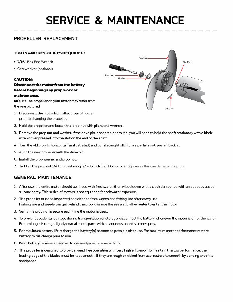
Propeller
Slot End
Drive Pin
Prop NutWasher
PROPELLER REPLACEMENT
TOOLS AND RESOURCES REQUIRED:
• 7/16” Box End Wrench
• Screwdriver (optional)
CAUTION: Disconnect the motor from the battery before beginning any prop work or maintenance.NOTE: The propeller on your motor may diff er from the one pictured.
1. Disconnect the motor from all sources of powerprior to changing the propeller.
2. Hold the propeller and loosen the prop nut with pliers or a wrench.
3. Remove the prop nut and washer. If the drive pin is sheared or broken, you will need to hold the shaft stationary with a bladescrewdriver pressed into the slot on the end of the shaft.
4. Turn the old prop to horizontal (as illustrated) and pull it straight off . If drive pin falls out, push it back in.
5. Align the new propeller with the drive pin.
6. Install the prop washer and prop nut.
7. Tighten the prop nut 1/4 turn past snug [25-35 inch lbs.] Do not over tighten as this can damage the prop.
GENERAL MAINTENANCE
1. After use, the entire motor should be rinsed with freshwater, then wiped down with a cloth dampened with an aqueous basedsilicone spray. This series of motors is not equipped for saltwater exposure.
2. The propeller must be inspected and cleaned from weeds and fi shing line after every use. Fishing line and weeds can get behind the prop, damage the seals and allow water to enter the motor.
3. Verify the prop nut is secure each time the motor is used.
4. To prevent accidental damage during transportation or storage, disconnect the battery whenever the motor is off of the water.For prolonged storage, lightly coat all metal parts with an aqueous based silicone spray.
5. For maximum battery life recharge the battery(s) as soon as possible after use. For maximum motor performance restorebattery to full charge prior to use.
6. Keep battery terminals clean with fi ne sandpaper or emery cloth.
7. The propeller is designed to provide weed free operation with very high effi ciency. To maintain this top performance, the leading edge of the blades must be kept smooth. If they are rough or nicked from use, restore to smooth by sanding with fi nesandpaper.
SERVICE & MAINTENANCE

Propeller
Slot End
Drive Pin
Prop NutWasher
PROPELLER REPLACEMENT
TOOLS AND RESOURCES REQUIRED:
• 7/16” Box End Wrench
• Screwdriver (optional)
CAUTION:Disconnect the motor from the batterybefore beginning any prop work ormaintenance.NOTE: The propeller on your motor may differ fromthe one pictured.
1. Disconnect the motor from all sources of powerprior to changing the propeller.
2. Hold the propeller and loosen the prop nut with pliers or a wrench.
3. Remove the prop nut and washer. If the drive pin is sheared or broken, you will need to hold the shaft stationary with a bladescrewdriver pressed into the slot on the end of the shaft.
4. Turn the old prop to horizontal (as illustrated) and pull it straight off. If drive pin falls out, push it back in.
5. Align the new propeller with the drive pin.
6. Install the prop washer and prop nut.
7. Tighten the prop nut 1/4 turn past snug [25-35 inch lbs.] Do not over tighten as this can damage the prop.
GENERAL MAINTENANCE
1. After use, the entire motor should be rinsed with freshwater, then wiped down with a cloth dampened with an aqueous basedsilicone spray. This series of motors is not equipped for saltwater exposure.
2. The propeller must be inspected and cleaned from weeds and fishing line after every use.Fishing line and weeds can get behind the prop, damage the seals and allow water to enter the motor.
3. Verify the prop nut is secure each time the motor is used.
4. To prevent accidental damage during transportation or storage, disconnect the battery whenever the motor is off of the water.For prolonged storage, lightly coat all metal parts with an aqueous based silicone spray.
5. For maximum battery life recharge the battery(s) as soon as possible after use. For maximum motor performance restorebattery to full charge prior to use.
6. Keep battery terminals clean with fine sandpaper or emery cloth.
7. The propeller is designed to provide weed free operation with very high efficiency. To maintain this top performance, theleading edge of the blades must be kept smooth. If they are rough or nicked from use, restore to smooth by sanding with finesandpaper.
1. Motor fails to run or lacks power:
• Check battery connections for proper polarity.
• Make sure terminals are clean and corrosion free. Use fi ne sandpaper or emery cloth to clean terminals.
• Check battery water level. Add water if needed.
2. Motor loses power after a short running time:
• Check battery charge. If low, restore to full charge.
3. Motor is diffi cult to steer:
• Check steering cables for proper tension. Adjust as necessary.
4. You experience prop vibration during normal operation:
• Remove and rotate the prop 180°. See removal instructions in the Propeller Replacement Section.
5. Experiencing interference with your fi shfi nder:
TROUBLESHOOTING & REPAIR

1
2
5
6
7
819
18
20
21
2324
15
12
10
30
3
22
4
28
25
29
27
9
63
64
65
66
67
66
68
69
71 71
7374
75
76
139140141
77
7978
80
81
82
107
113
115114
121
129
51
126
127
142
84
26
128
131
132133
41
50
40
36
3549
424455
6061
5957
56
58
14754
37
73A
62
52
48
53
70
137
72
120
85
8687
100
91
9293
94
9695 97
9899
103
105
106
108
109
110
116
118
119
122
124
125
129130
134
136
123
104
9088
135129
34
145
144
33
31
143
37
46
47
32
4543
This page provides Minn Kota® WEEE compliance disassembly instructions. For more information about where you should dispose of your waste equipment for recycling and recovery and/or your European Union member state requirements, please contact your dealer or distributor from which your product was purchased.
Tools required, but not limited to: fl at head screw driver, Phillips screw driver, socket set, pliers, wire cutters.
EDGE 7070 LBS THRU� - 24 VOLT - 45”/52” SHA�
2274997 rev F ECN 35972 7/14
PARTS DIAGRAM
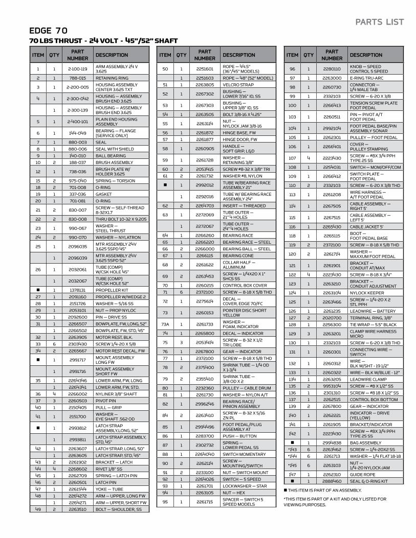
EDGE 7070 LBS THRU� - 24 VOLT - 45”/52” SHA�
ITEM QTYPART
NUMBERDESCRIPTION
1 1 2-100-119 ARM � SEMBLY 24 V 3.625
2 1 788-015 R� AINING RING
3 1 2-200-005 HOUSING � SEMBLY CENTER 3.625 TXT
4 1 2-300-042 HOUSING — � SEMBLY BRUSH END 3.625
1 2-300-139 HOUSING — � SEMBLY BRUSH END 3.625
5 1 2-400-101 P� IN END HOUSING � SEMBLY
6 1 144-049 BEARING — F� NGE [SERVICE ONLY]
7 1 880-003 SEAL
8 1 880-006 SEAL WITH SHIELD
9 1 140-010 BALL BEARING
10 2 188-037 BRUSH � SEMBLY
12 1 738-036 BRUSH P� TE W/HOLDER 3.625
15 2 975-040 SPRING — TORSION
18 2 701-008 O-RING
19 1 337-036 G� K�
20 1 701-081 O-RING
21 2 830-007 SCREW — SELF-THREAD 8-32X1.7
22 2 830-008 THRU BOLT 10-32 X 9.205
23 1 990-067 W� HER —� EEL THRU�
24 2 990-070 W� HER — NY� TRON
25 1 2096035 MTR � SEMBLY 24V 3.625 5SPD 45”
1 2096039 MTR � SEMBLY 24V 3.625 5SPD 52”
26 1 2032061 TUBE (COMP)W/� K HOLE 45”
1 2032067 TUBE (COMP)W/� K HOLE 52”
n 1 1378131 PROPELLER KIT
27 1 2091160 PROPELLER W/WEDGE 2
28 1 2151726 W� HER — 5/16 SS
29 1 2053101 NUT — PROP NYLOC
30 1 2092600 PIN — DRIVE SS
31 1 2266507 BOWP� TE, FW, LONG, 52”
1 2266502 BOWP� TE, FW, � D, 45”
32 1 2263905 MOTOR R� , BLK.
33 6 2303430 SCREW 1/4-20 X 5/8
34 2 2265667 MOTOR R� DE� L, FW
n 1 2991717 MOUNT, � SEMBLY LONG FW
1 2991716 MOUNT, � SEMBLY SHORT FW
35 1 2264346 LOWER ARM, FW, LONG
1 2264341 LOWER ARM, FW, � D.
36 4 2266002 NYLINER 3/8” SHA�
37 3 2260503 PIVOT PIN
40 1 2150405 PULL — GRIP
41 1 2151700 W� HER —EYE SHA� .562 OD
n 1 2993812 � TCH � RAP � SEMBLY,LONG, 52”
1 2993811 � TCH � RAP � SEMBLY, � D, 45”
42 1 2263607 � TCH � RAP, LONG, 50”
1 2263605 � TCH � RAP, � D, 45”
43 2 2261902 BRACK� — � TCH
44 4 2268602 RIV� 1/8” SS
45 1 2262709 SPRING — � TCH PIN
46 2 2260501 � TCH PIN
47 1 2261544 YOKE — TUBE
48 1 2264272 ARM — UPPER, LONG FW
1 2264271 ARM — UPPER, SHORT FW
49 2 2263510 BOLT — SHOULDER, SS
ITEM QTYPART
NUMBERDESCRIPTION
50 1 2251601 ROPE — 44.5”(36”/45” MODE� )
1 2251603 ROPE — 48” (52” MODEL)
51 1 2263805 VELCRO � RAP
52 1 2267302 BUSHING —LOWER 7/16” ID, SS
53 1 2267303 BUSHING —UPPER 3/8” ID, SS
54 1 2263505 BOLT 3/8-16 X 4.25”
55 1 2263114 NUT —NYLOCK JAM 3/8-16
56 1 2261872 HINGE B� E, FW
57 1 2261877 HINGE DOOR, FW
58 1 2260905 HANDLE —SO� GRIP, L&D
59 1 2261728 W� HER —R� AINING 3/8”
60 2 2053415 SCREW #8-32 X 3/8” TRI
61 2 2261732 W� HER #8, NYLON
n 1 2992012 TUBE W/BEARING RACE � SEMBLY 21”
1 2292016 TUBE W/ BEARING RACE � SEMBLY 24”
62 2 2264703 INSERT — THREADED
63 1 2272069 TUBE OUTER —21” 4 HOL�
1 2272067 TUBE OUTER —24” 4 HOL�
64 1 2266260 BEARING RACE
65 1 2266220 BEARING RACE — � EEL
66 2 2266000 BEARING BALL — � EEL
67 1 2266115 BEARING CONE
68 2 2261622 COL� R HALF —ALUMINUM
69 2 2263453 SCREW — 1/4X20 X 1” SH� SS
70 1 2260215 CONTROL BOX COVER
71 6 2372100 SCREW — 8-18 X 5/8 THD
72 1 2275614 DE� L —COVER, EDGE 70/FC
73 1 2260153 POINTER DISC SHORT YELLOW
73A 1 2261733 W� HER —FOAM, INDI� TOR
74 1 2265800 DE� L — INDI� TOR
75 3 2053414 SCREW — 8-32 X 1/2TRI LOBE
76 1 2267800 GEAR — INDI� TOR
77 1 2372100 SCREW — 8-18 X 5/8 THD
78 2 2375400 SHRINK TUBE — 1/4 OD X 1-3/4
79 2 2355410 SHRINK TUBE —3/8 OD X 2
80 1 2232360 PULLEY — � BLE DRUM
81 1 2261730 W� HER — NYLON A/T
82 1 2996246 BEARING RACE/PINION � SEMBLY
84 2 2263410 SCREW — 8-32 X 5/16 ZN PL
85 1 2994496 FOOT PEDAL/PLUG � SEMBLY AT
86 1 2283700 PUSH — BUTTON
87 1 2302732 SPRING —LOWER PEDAL SS
88 1 2264040 SWITCH MOMENTARY
90 2 2262114 SCREW —MOUNTING/SWITCH
91 2 2233100 NUT — SWITCH MOUNT
92 1 2264026 SWITCH — 5 SPEED
93 1 2261701 LOCKW� HER — � AR
94 1 2263105 NUT — HEX
95 1 2261715 SPACER — SWITCH 5 SPEED MODE�
ITEM QTYPART
NUMBERDESCRIPTION
96 1 2280110 KNOB — SPEEDCONTROL 5 SPEED
97 1 2263000 E-RING TRU-ARC
98 1 2260730 CONNE� OR —1/4 MALE TAB
99 1 2332103 SCREW — 6-20 X 3/8
100 1 2266413 TENSION SCREW P� TE FOOT PEDAL
103 1 2260511 PIN — PIVOT A/TFOOT PEDAL
104 1 2992104 FOOT PEDAL B� E/PIN � SEMBLY SONAR
105 1 2262301 PULLEY — FOOT PEDAL
106 1 2266401 COVER —PULLEY � AMPING
107 4 2223430 SCREW — #8X 3/4 PPH TYPE 25 SS
108 1 2254031 SWITCH — MOM/OFF/COM
109 1 2266412 SWITCH P� TE —FOOT PEDAL
110 2 2332103 SCREW — 6-20 X 3/8 THD
113 1 2261208 WIRE HARN� S —A/T FOOT PEDAL
114 1 2267505 � BLE � SEMBLY —RIGHT 5’
115 1 2267515 � BLE � SEMBLY —LE� 5’
116 1 2265430 � BLE JACK� 5’
118 1 2265115 BOOT —FOOT PEDAL B� E
119 2 2372100 SCREW — 8-18 X 5/8 THD
120 2 2261714 W� HER —MAXXUM FOOT PEDAL
121 1 2261901 BRACK� —CONDUIT AT/MAX
122 4 2223430 SCREW — 8-18 X 3/4”
123 1 2263210 BRACK� —CONDUIT ADJU� MENT
124 1 2263104 NYLOCK KEEPER
125 1 2263466 SCREW — 1/4-20 X 2 � L PPH
126 1 2261235 LEADWIRE — BATTERY
127 2 2020700 TERMINAL RING, 3/8”
128 1 2256300 TIE WRAP — 5.5” B� CK
129 3 2263201 C� MP WIRE HARN� S MICRO
130 1 2332103 SCREW — 6-20 X 3/8 THD
131 1 2260301 CONNE� ING WIRE — SWITCH
132 1 2260312 WIRE —BLK W/SHT - 19 1/2”
133 1 2260322 WIRE— BLK W/BLUE - 12”
134 1 2263205 LEADWIRE C� MP
135 2 9953104 SCREW — #8 X 1/2” SS
136 1 2301310 SCREW — #8 18 X 1/2” SS
137 1 2262515 CONTROL BOX BOTTOM
139 2 2267800 GEAR — INDI� TOR
140 1 2262221 INDI� TOR — DRIVE (YELLOW)
141 1 2261905 BRACK� /INDI� TOR
142 1 2223430 SCREW — #8X 3/4 PPH TYPE 25 SS
n 1 2994838 BAG � SEMBLY
*143 6 2263462 SCREW — 1/4-20X2 SS
*144 6 2261713 W� HER — 1/4 F� T 18-18
*145 6 2263103 NUT —1/4-20 NYLOCK-JAM
147 1 2262310 GUIDE ROPE
n 1 2888460 SEAL & O-RING KIT
n THIS ITEM IS PART OF AN � SEMBLY.
*THIS ITEM IS PART OF A KIT AND ONLY LI� ED FORVIEWING PURPOS� .
PARTS LIST

ENVIRONMENTAL COMPLIANCE STATEMENT:
It is the intention of JOME to be a responsible corporate citizen, operating in compliance with known and applicable environmental regulations, and a good neighbor in the communities where we make or sell our products.
WEEE DIRECTIVE:
EU Directive 2002/96/EC “Waste of Electrical and Electronic Equipment Directive (WEEE)” impacts most distributors, sellers, and manufacturers of consumer electronics in the European Union. The WEEE Directive requires the producer of consumer electronics to take responsibility for the management of waste from their products to achieve environmentally responsible disposal during the product life cycle.WEEE compliance may not be required in your location for electrical & electronic equipment (EEE), nor may it be required for EEE designed and intended as fi xed or temporary installation in transportation vehicles such as automobiles, aircraft, and boats. In some European Union member states, these vehicles are considered outside of the scope of the Directive, and EEE for those applications can be considered excluded from the WEEE Directive requirement.
This symbol (WEEE wheelie bin) on product indicates the product must not be disposed of with other household refuse. It must be disposed of and collected for recycling and recovery of waste EEE. Johnson Outdoors Inc. will mark all EEE products in accordance with the WEEE Directive. It is our goal to comply in the collection, treatment, recovery, and environmentally sound disposal of those products; however, these requirement do vary within European Union member states. For more information about where you should dispose of your waste equipment for recycling and recovery and/or your European Union member state requirements, please contact your dealer or distributor from which your product was purchased.
DISPOSAL:
Minn Kota motors are not subject to the disposal regulations EAG-VO (electric devices directive) that implements the WEEE directive. Nevertheless never dispose of your Minn Kota motor in a garbage bin but at the proper place of collection of your local town council.
Never dispose of battery in a garbage bin. Comply with the disposal directions of the manufacturer or his representative and dispose of them at the proper place of collection of your local town council.
WARNING: This product contains chemical(s) known to the state of California to cause cancer and/or reproductive toxicity.
COMPLIANCE STATEMENTS

• 60-Amp Circuit Breaker
• Mounting Brackets
• Stabilizer Kits
• Extension Handles
• Battery Connectors
• Battery Boxes
• Quick Connect Plugs
RECOMMENDED ACCESSORIES
ON-BOARD & PORTABLE BATTERY CHARGERSStop buying new batteries and start taking care of the ones you’ve got. Many chargers can actually damage your battery over time – creating shorter run times and shorter overall life. Digitally controlled Minn Kota chargers are designed to provide the fastest charge that protect and extend battery life.
TALON SHALLOW WATER ANCHORTalon deploys faster, holds stronger and runs quieter than any other shallow water anchor. Available in depths up to 12’ and bold color options, it boasts an arsenal of features and innovations that no other anchor can touch:
MINN KOTA ACCESSORIESWe offer a wide variety of trolling motor accessories, including:
MK212DMK345PC MK105P
• Vertical, multi-stage deployment
• User-Selectable Anchoring Modes
• 2x Anchoring Force
• Fast Deploy
• Auto Up/Down
• Triple Debris shields*
• Built-In Wave Absorption
• Noise Dissipation
• Versatile Adjustments
*available on 10’ and 12’ models only
Find out more about performance boat parts and hardware we have.