minipurge type z(y) cf manual ml432 - expo … type z(y) cf manual ml432 ... section 0 description...
TRANSCRIPT

ML432 | v16 08-Dec-17
MiniPurge Type Z(Y) CF Manual
ML432
This manual covers Mini-Z(Y)-Purge Continuous Flow Size: 1 & 2
Mounting Options: bp, pm, nm, ss Output Options: IS, PO CONTENTS: 1. Specification Sheet – MiniPurge Type Z(Y) Systems 2. Application Suitability 3. Installation, Operation and Maintenance for CF Systems
Section 0. Description and Principle of Operation Section 1. Installation of the System Section 2. Operation of the System Section 3. Maintenance of the System Section 4. Fault Finding - CF Systems Section 5. Annex of Options Fitted
4. Drawings 5. Certificates


ML432 | v16 Expo Technologies UK T: +44 (0) 20 8398 8011 E: [email protected]
Expo Technologies US T: +1 (440) 247 5314 E:[email protected]
Expo Technologies China T: +86 532 8906 9858 E: [email protected]
1. Specification Sheet – MiniPurge Type Z(Y) Systems
Supply Pressure 60 psi / 0.4MPa / 4 bar must be regulated at inlet.
Maximum supply pressure 115 psi / 0.8MPa / 8 bar. Compressed Air / Nitrogen
Flow & Pressure Sensor
One sensor for both “Low Pressure and Flow” : 1 "WC / 250 Pa ( 2.5 mbarg ) Spark Arrestor Unit: MiniPurge Size 1 MiniPurge Size 2 Model No SAU25 SAU40 Purge / Dilution Flow Rate 0.4 to 8 scfm / 10 to 225 Nl/min 8 to 16 scfm / 255 to 450 Nl/min
8 User selectable orifice plates 4 User selectable orifice plates Material Stainless Steel Stainless Steel
Relief Valve Model No RLV25/ss RLV36/ss
Opening Pressure 4” WC / 1 kPa (10 mbar) 4” WC / 1 kPa (10 mbarg) Material : 316L Stainless Steel,
Spark Arrestor: Stainless Steel mesh, Gasket: Neoprene
Action on “Loss of Pressure”: ALARM ONLY
Size
1 = Sub MiniPurge Purge flow rate: 4 - 8 scfm / 10 - 225 Nl / min
2 = MiniPurge Purge flow rate: 8 - 16 scfm / 255 - 450 Nl /min
Purge System Type
07 = MiniPurge
Approval / Certification
Z = Y =
Europe EN 60079-0, EN 60079-2 Sira 01ATEX1295X
0518 II 3 (2) G D 0518 II 2 (2) G D Ex [pzc] IIC T6 Gb Ex [pyb] IIC T6 Gb Ex [pzc] IIIC T85ºC Db Ex [pyb] IIIC T85ºC Db Tamb -20ºC +55ºC Tamb -20ºC +55ºC
IEC IEC 60079-0, IEC 60079-2 IECEx SIR 07.0027X Ex [pzc] IIC T6 Gb Ex [pyb] IIC T6 Gb Ex [pzc] IIIC T85ºC Db Ex [pyb] IIIC T85ºC Db Tamb -20ºC +55ºC Tamb -20ºC +55ºC
USA / Canada NFPA 496 FM 1X8A4AE Class I Div 2 Class I Div 1 Groups A, B, C & D Groups A, B, C & D Tamb = 60oC Tamb = 60oC UL E190061 Class I Div 2 Class I Div 1 Groups A, B, C & D Groups A, B, C & D Brazil INMETRO - TÜV 12.1462X Ex [pzc] IIC T6 Gb Ex [pyb] IIC T6 Gb Ex [pzc] IIIC T85ºC Db Ex [pyb] IIIC T85ºC Db Tamb -20ºC +55ºC Tamb -20ºC +55ºC For limitations and conditions of use refer to the applicable certificate at the back of this manual.
Alarm (Signals)
IS = Internal Switch ‘Alarm’ : Dry, VFC, SPST N/O Contact For Intrinsically Safe Circuits: Install to EP80-2-11 Ci = 0 Li = 0 Umax = 30 Vdc, Imax = 101 mA Umax = 19.2 Vdc, Imax = 350 Ma Hermetically Sealed Switch (ATEX/IECEx only) Ex mc IIC T5 Gc Ex mc IIIC T100ºC Dc Vmax = 254 Vac, Imax = 0.7 A
PO = Pneumatic Output “Alarm” : Loss of Pressure = No signal ”Pressurized” = at supply pressure
MiniPurge Housing
bp = Back Plate (Top/Side Mount) 316L Stainless Steel (NROB finish)
pm = Panel Mount (Side/Front Mount) 316L Stainless Steel (NROB finish)
nm = Non Metallic (Top/Side Mount) Polystyrene c/w clear cover
ss = 316L Stainless Steel (NROB finish) Neoprene “Top” Mount Gasket, loose
Purging Method
CF = Continuous Flow
Model No. (Example): 07 1 ZCF / ss / IS (Note: Not all codes are applicable)

ML432 | v16 Expo Technologies UK T: +44 (0) 20 8398 8011 E: [email protected]
Expo Technologies US T: +1 (440) 247 5314 E:[email protected]
Expo Technologies China T: +86 532 8906 9858 E: [email protected]
2. Application Suitability
MiniPurge Systems are certified for use in Hazardous Areas, where the Hazardous Area is non-mining (i.e. above ground) and the hazard is caused by flammable gasses, vapours or dust. Mini-Z-Purge Systems may be used in IECEx, ATEX Zone 2(22) - Category 3 and NEC 500 Class I, Div 2. Mini-Y-Purge Systems may be used in IECEx, ATEX Zone 1(21) - Category 2 and NEC 500 Class I, Div 1. MiniPurge systems may be used for hazards of any gas group. However, apparatus associated with the MiniPurge system, such as Non-Incendive, Intrinsically Safe signalling circuits and flameproof enclosures containing switching devices may be limited in their gas group. The certification documentation supplied with any such devices must be checked to ensure their suitability. This system is designed for use primarily with compressed air. Where other inert compressed gasses are used (Nitrogen, for example) the user must take suitable precautions so that the build up of the inert gas does not present a hazard to health. Consult the Control of Substances Hazardous to Health (COSHH) data sheet for the gas used. Where a risk of asphyxiation exists, a warning label must be fitted to the Pressurized Enclosure. The following materials are used in the construction of MiniPurge systems. If substances that will adversely affect any of these materials are present in the surrounding environment, please consult Expo for further guidance. Materials of construction:
Stainless Steel Aluminium Acrylic Mild (carbon) Steel Nylon Silicone Rubber Brass Polyurethane Neoprene

ML432 | v16 Expo Technologies UK T: +44 (0) 20 8398 8011 E: [email protected]
Expo Technologies US T: +1 (440) 247 5314 E:[email protected]
Expo Technologies China T: +86 532 8906 9858 E: [email protected]
3. Installation, Operation and Maintenance for CF Systems
This MiniPurge is designed for use under normal industrial conditions of ambient temperature, humidity and vibration. Please consult Expo before installing this equipment in conditions that may cause stresses beyond normal industrial conditions. The MiniPurge system shall be installed and operated in accordance with relevant standards, such as IEC / EN 60079-14, NEC 500, NFPA 496 and any local codes of practice that are in force. For IEC / ATEX applications, references to the NFPA 496 within the ML383, should be replaced by the equivalent clause in IEC / EN 60079-2. For IEC / ATEX applications, the "Example calculations:" in section 1.1.4 within ML383 should read:
If the PE external dimensions indicate a volume of 500 Litres then, 500 litres enclosure volume x 5 volume changes = 12 minutes purge time
225 litres/minute purge flow rate

Expo Technologies Limited Page 1 of 6 ML383 issue 5 – 04.06.15
Installation, Operation and Maintenance Manual for
MiniPurge Continuous Flow (Model CF)
conforming to NFPA 496
IMPORTANT NOTE It is essential, to ensure conformity with the standard,
that the user of the system observes the following instructions:
Please refer to the latest standard for detailed requirements and definitions.
(N.B. These instructions apply only to the Pressurizing system. It is the responsibility of the manufacturer of the Pressurized Enclosure to provide equivalent instructions for the Enclosure.)
Contents: Section 0 Description and Principle of Operation Section 1 Installation of the System Section 2 Operation of the System Section 3 Maintenance of the System Section 4 Fault Finding Section 5 Annex (if applicable)
Section 0 Description and Principle of Operation
All MiniPurge pressurization systems provide:
a) a method of pressurizing a Pressurized Enclosure (PE) while at the same time compensating for any leakage, together with
b) a method of purging the enclosure, before power is turned on, to remove any flammable gas that may have entered the enclosure while it was not pressurized.
Continuous Flow Systems, Model CF, allow air to flow through the PE continuously by having a fixed outlet aperture, which does not have any means of closure. The act of pressurizing the enclosure forces air to “leak” through the outlet aperture. The Control Unit admits sufficient air at the inlet to the PE to compensate for the air leaking out of the outlet aperture as well as from any other accidental leakage paths. The flow rate is constant both during purging and thereafter.
The Purging Flow rate is monitored by a separate “Purge Flow Sensor” located in the CU, which detects the differential pressure across the purge flow orifice located directly before the Outlet Orifice. The Purge Flow Sensor is set to operate when the desired differential pressure is exceeded. The output from the Flow Sensor is indicated on the CU and on “X” Pressurization systems, used to operate the automatic purge timer. Both Enclosure Pressure and Purge Flow have to be correct before the Purge Timer can start.
Type CF systems comprises the following major parts:
- A Control Unit (CU) containing as a minimum, for “Y” and “Z” Pressurization, a Flow Control Valve (FCV), Minimum Pressure and Purge Flow sensing devices, and a “Pressurized”/”Alarm” indicator. The CU supplies a “Pressurized” signal showing whether the PE pressure is satisfactory or not.
For Type “X” Pressurization, the CU has, in addition, a fully automatic Purging controller with a purge timer and electrical power switch interlock.
Note: For “Y” Pressurization, the electrical equipment inside the protected enclosure shall meet the requirement for Division 2 or Class 2 locations.
- A Relief Valve (RLV) fitted to the PE to provide a means of limiting the maximum pressure experienced by the enclosure during operation.
The RLV model number has suffixes giving the diameter of the valve aperture (in millimeters) and material, e.g. RLV **/cs (Carbon Steel) or /ss (Stainless Steel). All RLVs incorporate a Spark Arrestor to prevent sparks being ejected from the PE through the RLV aperture. The Relief Valve is fitted solely as a safety device and does not open in normal operation.
- An Outlet Orifice, which has been pre-calibrated so that the pressure drop at the desired flow rate is known. The Minimum Pressure Sensor within the CU will be set to the same figure as the pressure drop. When the PE pressure exceeds the calibrated pressure the Continuous Flow must be taking place.
The system is provided with one of the following types of calibrated Outlet Orifices. Please consult the system specification sheet to determine which has been supplied. The choice:
- Type SAU** where the Outlet Orifice disk is removable and can be easily changed by the user to give different flow rates according to the size of the PE and the available air supply capacity. (** denotes the metric thread size of the SAU body)
- SA** where the orifice size is fixed and the way to change the flow rate is either to change the setting of the Minimum Pressure Sensor or to replace the SA with one of another size. (** denotes the nominal thread size of the SA body)
- For low flow rates, the Outlet Orifice may be incorporated within the Relief Valve making use of the existing Spark Arrestor. The Relief Valve will then have a suffix /CF**, where ** is the orifice size in millimeters.

Expo Technologies Limited Page 2 of 6 ML383 issue 5 – 04.06.15
Section 1 Installation of the System
The installation of the MiniPurge system, the protective gas supply, any alarm device should be in accordance with the requirements of NFPA 496.
The electrical installation associated with the MiniPurge system shall conform to the local codes and the relevant clauses of NFPA 496.
All electrical parts of the MiniPurge system shall be installed in accordance with the applicable requirements of the NEC for USA and CEC for Canada.
1.1 Installation of the Expo CF System
1.1.1 The Expo system should be installed either directly on or as close as possible to the Pressurized Enclosure (PE). It should be installed so that the system indicators may be readily observed.
1.1.2 All parts of any system carry a common serial number. If installing more than one system, ensure that this commonality is maintained on each installation.
1.1.3 Any tubing, conduit and fittings used to connect to the PE should be metallic, or, if non-metallic, conform to the local codes for flammability ratings. No valve may be fitted in any tube connecting the Expo system to the PE.
1.1.4 The user or manufacturer of the PE shall determine the volume of the PE, the necessary purging volume, and the time to be allowed for purging, using the chosen Expo system purging flow rate. It is the user’s responsibility to verify or enter this data on the PE and/or Expo system nameplate. Ask Expo if in doubt.
Example calculations:
a) If the PE external dimensions give a volume of 20 cubic feet, and it is NOT a motor, multiply the volume by four to get the Purging Volume i.e. 80 cubic feet. Divide the Purging Volume by the purge rate e.g. 32 cubic feet per minute, and round up to the next even minute above, i.e. purging time would be 4 minutes.
b) If the PE is a motor, multiply the internal free volume by ten to get the Purging Volume. For the above example, the Purging time would be 8 minutes.
For Type “Y” or “Z” Pressurization, the protected equipment may be permitted to be energized immediately where 25 Pa (0.1”WC) exist in the enclosure and the enclosure is known to be below the ignitable concentration of combustible material.
1.1.5 If the PE contains an internal source of release of flammable gas or vapor, the procedures for assessment of the release as given in NFPA 496 shall be observed. User must take precaution if abnormal release of flammable gas or vapor within the enclosure can affect the external area.
1.1.7 Where a release of flammable gas or vapor within an enclosure can occur either in normal condition or abnormal operation, protection shall be provided by one of the step as specified in NFPA 496.
For more information on enclosure containing internal source of release or enclosure containing an open flame, contact Expo Technologies.
The user must verify that the specification of the Expo system e.g. pressures, continuous flow (dilution) rate and type of protective gas are correct for the specific application.
1.1.8 More than one PE can be protected by a single system. If PEs are connected and purged in “series” e.g. “Daisy Chained”, the Outlet Orifice must be fitted on the last enclosure with the Purge Inlet to the first enclosure. The Relief Valve may be fitted at any convenient location except when it has the option code /CF in which case it must be fitted on the last enclosure. The bore and length of the tube or conduit used to interconnect the enclosures is critical and will determine the maximum pressure experienced by the first enclosure in the series. Advice on sizing can be obtained from your Expo Technologies, sales office. The test pressure for all the enclosures should be 3 times the pressure inside the first enclosure when purging is taking place.
If PE’s are to be connected in parallel each enclosure must have its own Outlet Orifice/Spark Arrestor, Relief Valve, Purge Flow Sensor and Pressure Sensor. System “Models” can be mixed e.g. Model LC for one enclosure and Model CF for another. An example would be a Gas Chromatograph instrument. Expo systems with this facility have option code /TW.
1.2 Quality and Installation of the Pressurizing Air or Inert Gas Supply
1.2.1 The source of the compressed air must be in a non-classified area. Inert gas may be used as an alternative to compressed air.
1.2.2 All pipe connection for the protective gas shall be protected from mechanical damage; where the source of the compressed air intake line passes through a classified location, the construction shall be of non-combustible material, and designed to prevent leakage of flammable gases, vapours, or dust into the protective gas. It must be protected against mechanical damage and corrosion.
1.2.3 Unless a supply shut-off valve has been specially fitted within the Expo system, a valve with the same, or larger, thread size as the Control Unit (CU) inlet fitting shall be fitted externally. In addition, for "Y" and "Z" Pressurization systems, a suitable nameplate shall be provided:
Note: To conform to NFPA: Any protected enclosure that can be isolated from the protective gas supply shall be equipped with an alarm and shall have this warning:
WARNING: PROTECTIVE GAS SUPPLY VALVE This valve must be kept open unless the area atmosphere is known to be below the ignitable concentration of combustible materials or unless all equipment within the protected enclosure is de-energized.

Expo Technologies Limited Page 3 of 6 ML383 issue 5 – 04.06.15
1.2.4 The tubing and fittings used must conform to 1.1.3 above.
1.3 Provision and Installation of Alarm Devices
Expo Technologies systems have a Minimum Pressure Sensor set to a pressure of at least 0.1” WC (0.25 mbar). When the PE pressure is above this set point the Sensor produces a positive "Pressurized" signal. This is displayed on the Red/Green indicator. This signal can be used to operate an electrical contact for a remote “Alarm”. The pneumatic signal may be supplied either
a) to a pressure operated switch (MiniPurge Option Code /IS) suitable for an Intrinsically Safe circuit, in accordance with Expo drawing EP80-2-11 (or for a Non-Incendive circuit in Division 2), or
b) to a bulkhead fitting where it is available to the user (MiniPurge Option Code /PO). It can then be used to operate an external electrical switch either local e.g. explosionproof, or remote in a non-classified area, or
c) to an external terminal box (MiniPurge Option Code /PN). This option is available with an auxiliary switch(es) for signal and circuit control, assessable to user via the external junction box. This switch is suitable for use in the Hazardous Location in accordance to NEC500/505 requirements.
When the enclosure pressure falls below the set point of the Sensor, the "Pressurized" signal is removed, i.e. the absence of the signal indicates an “Alarm” ("Pressure Failure") condition. If the system “Alarm” indicator is not located in a place where it can be readily observed, the user must make use of this external alarm facility in accordance with NFPA 496 requirements.
Example: The "Pressurized" signal can be used to produce an "Alarm" action by means of a conventional "pressure switch" set to operate at around 15 psi (1 bar). The "Pressurized" signal from the CU at 30 psi (2 bar) or more will hold the switch in the operated position until the CU detects a low pressure in the PE and removes the "Pressurized" signal. The Alarm switch will reset and its contacts can be used to operate a remote electrical alarm.
If the switch is located in the hazardous area it must either be part of an Intrinsically Safe circuit, or be suitably protected e.g. explosionproof. The pressure switch should be IS or explosionproof even if it is fitted within the PE.
Expo Technologies Tip: Exception: For a “Z Purge” system fitted in a Division 2 area a non-classified switch inside the PE can be used to operate a remote Alarm provided its electrical supply comes from within the PE (i.e. NOT PROVIDING DRY CONTACTS). When the PE is in use the Alarm can operate normally in response to the pneumatic signal from the CU with option /PO. When the PE is switched off there is no need for an alarm! Ask Expo for the circuit diagram.
The Alarm switch can also be located in a nearby non-classified location. To get the best response
time the switch should be as close as possible to the CU and the maximum length of tubing between the CU and the Alarm switch should not exceed 150 feet (45 m) unless “Quick Exhaust Valves” are used (please ask Expo if in doubt.)
Note: No valves may be fitted between the Expo system and the alarm switch.
1.4 Power Supplies and their Isolation
1.4.1 All power entering the PE shall be provided with a means of isolation. This requirement also applies to any external power sources that are connected to "dry contacts" or "volt-free contacts" within the PE.
1.4.1 Electrical power for the protective gas supply shall be from a separate power source. If the same power source for the pressurized enclosure is used, it shall be power off before any service disconnects for the enclosure.
Exception: Power to Intrinsically Safe, or other apparatus, which is already suitable for the location need not be isolated by the Expo Technologies system.
Expo Technologies Tip: It is recommended to fit dry or volt-free contacts in the non-classified area or inside an explosionproof box rather than inside the PE. Please ask Expo about “MiniPurge Interface Units” (MIU).
In the case of "X" Pressurization, the isolation of the power must be controlled by the Expo system using the "Purge Complete" pneumatic signal to operate a "Power Switch" in a similar manner to that described in 1.3 above.
In the case of "Y" or "Z" Pressurization the power may be controlled manually by the operator using a local isolating switch.
1.4.2 In accordance with NFPA496; Mini-X-Purge system shall be used on protected equipment requiring automatic shutdown, such as motors or transformers that could be overloaded or equipment that can develop higher temperature than the marked Temperature Class (temperature detector devices shall be provided to detect any increase in temperature). Expo Mini-X-Purge systems can have the "Action on Pressure Failure" (normally "Alarm and Trip") adjusted by the user to "Alarm Only". In case of an alarm, it is the responsibility of the user to de-energize the protected equipment as soon as possible. The system may require the addition of an “Alarm Only Kit” (/AO) to perform this function. Please contact Expo Sales office for further details.
Exception: The power may remain connected for a short period if immediate cut-off could result in a more hazardous condition and if audible and visual alarms are provided in a constantly attended location.

Expo Technologies Limited Page 4 of 6 ML383 issue 5 – 04.06.15
1.4.3 The Power (cut-off) Switch must be approved for the location or located in a non-classified area.
1.4.4 No valves are permitted between the Power Switch and the Expo system.
1.4.5 For "X" Pressurization, the PE door shall have fasteners that can be opened only by the use of a tool or key. Otherwise the additional requirements from NFPA 496 should apply.
1.4.6 Protection equipment containing hot parts requiring a cool-down period shall require the use of key or tool for opening.
Note: The door switch provided with the Expo system (when requested) can be either pneumatic or electric.
1.5 Marking
1.5.1 The MiniPurge system carries a nameplate and a specification sheet, which give specific data such as serial and models numbers, Pressure Sensor settings, flow rates and purge time.
1.5.2 Other marking, for the PE, required by the standard includes:
“WARNING - PRESSURIZED ENCLOSURE - This enclosure shall not be opened unless the area is known to be free of flammable materials or unless all devices within have been de-energized"
"Power shall not be restored after the enclosure has been opened until the enclosure has been purged for___minutes at a flow rate of___."
Expo note: It is understood that NFPA 496 requires the de-energization of all devices that are not suitable for the hazard e.g. devices that are not Explosionproof or Intrinsically Safe. For example, an explosionproof anti-condensation heater would not have to be de-energized.
1.5.3 If Inert Gas is used as the Protective Gas and a risk of asphyxiation exists, a suitable warning plate should be fitted to the PE.
Section 2 Operation of the System
2.1 Check that the system has been installed in accordance with Section 1 of this manual.
2.2 Disconnect the supply pipe from the inlet to the Control Unit (CU) and blow clean air through for at least 5 seconds per foot of length (15 sec/metre) to remove any debris, oil and condensation.
2.3 Connect a temporary pressure gauge or liquid manometer to the PE or CU “Pressure Test Point” (on the Low Pressure Sensor, by the removal of the Red plug - 4mm OD nylon tube).
2.4 Open the supply shutoff valve. On "X" Purge systems check that the internal gauge reads 30 psi (2 bar). If not, adjust the logic pressure regulator to suit (lift the red ring to unlock the knob first.)
2.5 Adjust the Flow Control Valve (FCV) so that the enclosure pressure rises to the point where the "Pressurized" indicator turns Green.
2.6 Continue to raise the PE pressure until the Relief Valve (RLV) opens. Verify that the RLV opens at or below
the figure specified in the documentation. Repeat the test several times.
2.7 Lower the PE pressure until the "Pressurized" indicator turns Red. Verify that the indicator turns Red at or above the pressure specified in the documentation. Check the external alarm contacts (if fitted).
Note: On Expo CF systems the Minimum Pressure Sensor set point may be significantly above the minimum of 0.1"WC (0.25 mbar) since it doubles as both the Pressure and the Purge Flow Sensor Set points of 1"WC (2.5 mbar) are common. Please check the documentation for the actual setting.
2.8 Open the FCV again and set the PE pressure to a level somewhere between the Minimum Pressure Sensor set point and the RLV opening pressures. This "working" pressure is not critical. Enough pressure to keep the “Pressurized” indicator Green is sufficient.
2.9 On "X" CF Purge systems the purge timer will start as soon as the “Pressurized” indicator turns Green. Check that the time delay between the indicator turning Green and the application of power to the PE is not less than the minimum time required to purge the PE. Times in excess of the minimum are permitted and a tolerance of +25% is normally acceptable. If the time is shorter than the minimum permitted, it must be adjusted accordingly.
MiniPurge uses a pneumatic incremental timer which is adjusted by fully opening or closing one or more of five screwdriver-operated valves, arranged in a block on the control logic manifold – see GA Drawing. The opening of each valve incrementally provides a fixed number of minutes of purging time as in the following table
Valve: 1 2 3 4 5
Minutes: 2 4 8 8 16
Thus for a 12 minute purge time, valves 2 and 3 would be open and the others closed. For twenty-four minutes, 4 and 5 would be open and the others closed. At least one valve must always be open and the screws must be at the appropriate limit of travel.
2.10 On “Y” and “Z” Purge systems the purge timing and power control is performed manually by the user.
Never turn on the power without purging first, unless you have proved that the interior of the PE is gas free and checked that the “Pressurized” indicator is green!
2.11 On "X" CF Purge systems, once the purge time is completed the “Purge Complete” indicator turns Green. With both indicators Green, the power will be turned on by the CU. Using the FCV reduce the PE pressure to the point where both indicators turn Red and check that the power is automatically turned off. When the PE pressure is restored the system should

Expo Technologies Limited Page 5 of 6 ML383 issue 5 – 04.06.15
re-purge the PE before power is once again turned on.
2.12 After initial commissioning, the system is ready for normal operation:
a) “X” CF Purge systems: Turn the air supply valve On or Off to start or stop the system. After this, the Pressurizing and Purging sequence is entirely automatic.
b) “Y” and “Z” Purge systems are started and stopped in the same way as “X” Purge system but the user must close the Power Switch only after the enclosure has been pressurized and purged sufficiently to ensure that the interior of the enclosure is gas free. The power should be shut off as soon as possible after a pressure failure. This is also the user’s responsibility.
Section 3 Maintenance of the System
The maintenance recommended for the system consists of the following, supplemented by any additional local requirements imposed by the authority having jurisdiction.
3.1 Initial Maintenance
Expo recommends that the commissioning test be repeated at least every six months. They include checking the opening pressure of the Relief Valve, setting of the Minimum Pressure Sensor, the "Normal Working Pressure" of the enclosure and, for "X" Purge systems, the setting of the purge timer (as described in Section 2 of this manual).
In addition, the following checks are also recommended at that time:
- Check the RLV and any other Spark Arrestors. Remove any debris or corrosion, or replace the Spark Arrestor with a spare.
- Check the condition of the air supply filter element. Clean or replace it as necessary.
3.2 Routine Maintenance
At least every two years, the following additional checks are recommended:
- Apparatus is suitable for the Hazardous Location
- There are no unauthorised modifications
- The source of air is uncontaminated
- The interlocks and alarms function correctly
- Approval labels are legible and undamaged
- Adequate spares are carried
- The action on pressure failure is correct
Section 4 Fault Finding for CF Systems
4.1 General
If the system does not behave in the manner described above there is a fault. Some of the more likely faults are dealt with below. If a cure cannot be effected by following the procedure shown below, please call Expo (24 hour answering) or your supplier for further assistance.
The system has been designed for ease of fault finding and many of the components fitted are plug-in or sub-
base mounted. Check components by substitution only after establishing that such action is necessary. If the system is less than 12 months old, parts under warranty should be returned to Expo Technologies for investigation, with a full report of the fault and the system serial number.
As with any pneumatic system the greatest enemies are water, oil and debris in the air supply. For this reason a dust and water filter may be fitted. But debris can enter from other sources and it is vital therefore that the procedures described in Section 2 are carried out before using the system for the first time, or following any disconnection of the pipework. Failure to perform this work may cause damage which will not be covered under warranty.
Fault Finding
NOTE: Before making the following checks verify that the main supply pressure is between 60 and 115 psi (4-8 bar) at the Control Unit (CU) and, for “X” Purge systems, the regulated pressure on the logic gauge is 30 psi (2 bar)
4.2 Minimum Pressure Alarm is ON Continuously (“Pressurized” Indicator is Red)
Possible cause 1: The PE pressure is too low. Try increasing the setting of the Flow Control Valve (FCV) to raise the pressure in the PE.
Possible cause 2: Enclosure fault?
- Is the ACTUAL PE pressure below the setting of the Minimum Pressure Sensor? Check it with a manometer or gauge.
- Is the Outlet Orifice (if separate from the RLV) fitted correctly?
- Is debris stuck on the face of the Relief Valve disk, holding the valve open?
- Has the PE door been closed and all conduit/cable glands sealed?
Possible cause 3: Insufficient purging Flow due to inadequate air supply pressure. Check the air supply pressure at the inlet to the CU when flow is taking place. Excessive pressure drop in the supply pipe is a very common cause of this problem. The supply pipe must be at least as big as the CU inlet fitting, i.e. at least ½” NB.
Possible cause 4: Excessive PE leakage. Check around the PE when flow is taking place. Any significant leakage must be cured. Has a Leakage Test been done? The total leakage should not exceed 10% of the Continuous Flow rate.
Possible cause 5: PE not strong enough. Repeat the PE pressure test. FM recommend that the PE is tested to three times the Relief Valve opening pressure e.g. 12”WC (30 mbar) for standard systems. Has this test been done?
Possible cause 6: System fault?
Has the pressure sensing tube been damaged?
If checks above reveal that the PE is correct the fault probably lies in the CU. The basic operation of the
Expo Technologies Limited Page 6 of 6 ML383 issue 5 – 04.06.15
Minimum Pressure Sensor can be checked by unscrewing the 2.4” diameter diaphragm and, by using a finger, blocking the threaded hole in the top of the valve module. The valve should operate and the indicator should turn Green. If this works correctly and the enclosure pressure is above the setting of the Minimum Pressure Sensor it is likely that the Pressure Sensor diaphragm needs re-calibrating or replacing (See 4.5).
4.3 Relief Valve Opens (Continuously or Intermittently)
Possible Cause 1: The PE pressure is too high. The Flow Control Valve (FCV) is too far open. Adjust the FCV as described in Section 2 above.
Possible Cause 2: Debris on the RLV disk allowing air to leak from the valve. Remove the RLV cover and clean the valve disk. The disk and spring may be removed from the RLV without affect the calibration.
4.4 System Fails to Switch Power On after the Purge Time has Elapsed? (“X” Purge Systems Only)
Possible cause 1: Is power available? Is the power disconnect closed? Are the fuses or circuit breaker OK?
Possible cause 2: System fault? Timer not timed out?
a) Has the “Pressurized” indicator been Green for the whole of the purge time?
b) Is the logic pressure gauge at 30 psi (-0, +10%)
c) Is there pressure at the Power Switch output bulkhead and at the Power Switch itself? Is the Switch set at 15 psi?
d) Is the pipe to the Power Switch airtight? The signal to the Power Switch bulkhead has a restrictor that limits the permissible leakage from the pipe.
e) Note the timer setting and reduce the time down to a low setting to check operation on a short purge time. If it works OK, gradually increase the time until either the time is correct, or it ceases to time out at all. In the latter case, there is an air leak in the timer circuit.
If possible establish the source of the leak with soapy water and retest the system. This will involve removing the chassis from the CU –be sure this is the cause before starting the work. It is VERY unusual!!
Ensure that the timer is returned to its original setting and the purge time checked before putting the system back into service.
Possible cause 3: Faulty Power Switch. Check the operation of the Power Switch. It should close above 20 psi (1.4 bar).
4.5 Pressure Sensor Calibration If it is decided that the Minimum Pressure Sensor needs recalibrating it can either be returned to Expo Technologies for this service or it can be done by the user as follows:
Disconnect the pressure sensing pipe from the top of the diaphragm. (It is a “push-in” quick release fitting; firmly push inwards the collar surrounding the pipe where it enters the fitting and then pull the pipe outwards while maintaining the pressure on the collar). Unscrew the 2.4” (60mm) diameter diaphragm housing from the top of the Sensor. Invert it and note the brass adjusting screw in the centre. Turning the screw inwards (clockwise) will lower the setting. It is likely that the screw will be very stiff due to the locking sealant. If the screw cannot be moved the application of gentle heat in the area of the brass screw can often help. DO NOT OVERHEAT!
4.6 Filter Cleaning If the filter element needs cleaning the transparent bowl can be unscrewed and removed. The filter element also unscrews and can then be cleaned in soapy water. Do not use solvents on any part of the filter assembly.
Expo Technologies Tip: If the bowl is very tight, it is easier to remove the filter by undoing the fitting that holds the filter into the CU. On Sub-MiniPurge systems it may be necessary to remove the Minimum Pressure Sensor diaphragm first.
Section 5 Annex of Options Fitted
Refer to the annexes of this manual for any options fitted as designated by the model code of the system.
Expo Technologies Ltd Expo Technologies Inc,
Unit 2 The Summit, 9140 Ravenna Road Unit #3,
Hanworth Road, Twinsburg,
Sunbury-On-Thames, OH 44087,
TW16 5DB. UK. U.S.A.

ML432 | v16 Expo Technologies UK T: +44 (0) 20 8398 8011 E: [email protected]
Expo Technologies US T: +1 (440) 247 5314 E:[email protected]
Expo Technologies China T: +86 532 8906 9858 E: [email protected]
4. Drawings
Consult the appropriate drawings according to the selected system.
SYSTEM *ZCF /bp/IS /bp/PO /pm/IS /pm/PO /nm/IS /nm/PO /ss/IS /ss/PO XBR-8TD0-012 MZ-1CF-17-CL SD7568 XBR-8TD0-010 MZ-1CF-23-GA MZ-1CF-26-GA XBR-8TD0-014 MZ-1CF-02-GA MZ-1CF-01-CL MZ-1CF-01-CT EP80-2-11 SAU25-GA SAU40-GA XSD-ATD0-003 XSD-RTD0-001 sheet 1 XSD-RTD0-001 sheet 2
5. Certificates
For certificates refer to ML569

FLA
TNE
SS
TO
BE
LE
SS
TH
AN
0.4
mm
OV
ER
AN
Y 1
00m
m L
EN
GTH
UN
SP
EC
IFIE
DTO
LER
AN
CE
S
MA
TER
IAL
DR'W
N
APP'
D
CHK'
D
DR
AW
ING
STA
TUS
:A
PP
RO
VE
D:
MO
D. N
o:D
ATE
:
ISS
UE
:
3rd
AN
GLE
PR
OJE
CTI
ON
DIM
EN
SIO
NS
IN m
m
DO
NO
T S
CA
LE
Expo
Tec
hnol
ogie
s Li
mite
d
JOB
No:
FIN
ISH
TITL
E
CU
STO
ME
R:
SH
EE
T N
o.O
F
SU
RR
EY
TW
16 5
DB
UN
ITE
D K
ING
DO
M
DR
AW
ING
No.
SC
ALE
The
cont
ents
of t
his
draw
ing
/ doc
umen
t are
Cop
yrig
ht ã
Exp
o Te
chno
logi
es L
imite
d. T
hey
are
to b
e tre
ated
as
conf
iden
tial a
nd a
re re
turn
able
upon
requ
est.
The
y ar
e no
t to
be c
opie
d or
com
mun
icat
ed in
par
t or i
n w
hole
with
out w
ritte
n co
nsen
t fro
m E
xpo
Tech
nolo
gies
Lim
ited,
nei
ther
are
they
to b
e us
ed in
any
way
aga
inst
our
inte
rest
s.
NO
DE
C P
LAC
E ±
0.5
1 D
EC
PLA
CE
±0.
22
DE
C P
LAC
E ±
0.1
CDM
PAO
PAO
PAO
DRAW
N05
/01/
04
1
XB
R-8T
D0-0
12Z(
Y)CF
& D
P /b
p QUIC
K INS
TALL
ATION
GUID
E
11
NTS
PAO
* CO
NTRO
L
UNIT
REL
IEF
VALV
E
SEL
ECT
ORIF
ICE
SPAR
KAR
REST
OR
PRES
SURI
ZED
ENCL
OSUR
E
*
FLOW
CONT
ROL
VALV
E
244
0608
/02/
08ML
C
Qui
ck I
nsta
llatio
n G
uide
FO
R C
F or
DP
syst
ems:
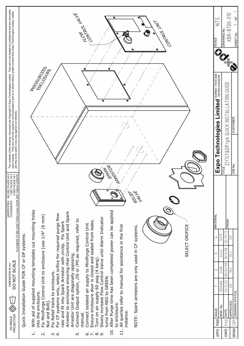
With
aid
of su
pplie
d m
ount
ing
tem
plat
e cu
t m
ount
ing
hole
s in
to t
he e
nclo
sure
.Fi
x M
iniP
urge
Con
trol
Uni
t to
enc
losu
re.
Fix
Rel
ief Val
ve t
o en
clos
ure.
For
CF
syst
ems
only
, se
lect
orific
e fo
r re
quired
pur
ge flo
w r
ate
and
fit in
to S
park
Arr
esto
r w
ith c
ircl
ip.
Fix
Spa
rk A
rres
tor
to e
nclo
sure
ens
urin
g th
at C
ontr
ol U
nit
and
Spa
rk A
rres
tor
Uni
t ar
e di
agon
ally
opp
osin
g.Con
nect
Out
put
optio
n, /
IS o
r /P
O a
s re
quired
, re
fer
to m
anua
l.Con
nect
isol
ated
air s
uppl
y to
Min
iPur
ge C
ontr
ol U
nit
Ensu
re e
nclo
sure
doo
r is
clo
sed
and
seal
ed fro
m le
aks.
Turn
on
air
supp
ly 6
0 ps
ig (
4 ba
rg).
Slo
wly
incr
ease
Flo
w C
ontr
ol V
alve
unt
il Ala
rm I
ndic
ator
tur
ns fro
m R
ED t
o G
REE
N.
Aft
er P
urge
tim
e ha
s be
en c
ompl
eted
pow
er c
an b
e ap
plie
d to
enc
losu
re.
All
quer
ies
refe
r to
man
ual f
or a
ssis
tanc
e in
the
first
inst
ance
.
NO
TE:
Spa
rk a
rres
tors
are
onl
y us
ed in
CF
syst
ems.
/P
O o
ptio
n sh
own
9. 11.
10.
5. 7. 8.6.4.2. 3.1.
344
4218
/3/0
8ML
C
459
7925
/11/
13SM

FLA
TNE
SS
TO
BE
LE
SS
TH
AN
0.4
mm
OV
ER
AN
Y 1
00m
m L
EN
GTH
UN
SP
EC
IFIE
DTO
LER
AN
CE
S
MA
TER
IAL
DR'W
N
APP'
D
CHK'
D
DR
AW
ING
STA
TUS
:A
PP
RO
VE
D:
MO
D. N
o:D
ATE
:
ISS
UE
:
3rd
AN
GLE
PR
OJE
CTI
ON
DIM
EN
SIO
NS
IN m
m
DO
NO
T S
CA
LE
Expo
Tec
hnol
ogie
s Li
mite
d
JOB
No:
FIN
ISH
TITL
E
CU
STO
ME
R:
SH
EE
T N
o.O
F
SU
RR
EY
KT7
0R
HU
NIT
ED
KIN
GD
OM
DR
AW
ING
No.
SC
ALE
The
cont
ents
of t
his
draw
ing
/ doc
umen
t are
Cop
yrig
ht ã
Exp
o Te
chno
logi
es L
imite
d. T
hey
are
to b
e tre
ated
as
conf
iden
tial a
nd a
re re
turn
able
upon
requ
est.
The
y ar
e no
t to
be c
opie
d or
com
mun
icat
ed in
par
t or i
n w
hole
with
out w
ritte
n co
nsen
t fro
m E
xpo
Tech
nolo
gies
Lim
ited,
nei
ther
are
they
to b
e us
ed in
any
way
aga
inst
our
inte
rest
s.
NO
DE
C P
LAC
E ±
0.5
1 D
EC
PLA
CE
±0.
22
DE
C P
LAC
E ±
0.1
PURG
E AIR
IN
LET
1/4"
NPT
F
IS P
RES
SU
RE
SW
ITCH
(IS
OPT
ION
)50
PLU
G 4
mm
(PE
TES
T PO
INT)
26
SEN
SO
R,
MIN
IMU
M P
RES
SU
RE
14
IND
ICATO
R "
ALA
RM
/PRES
SU
RIZ
ED"
8
FLO
W C
ON
TRO
L VALV
E17
ENCLO
SU
RE
PRES
SU
RE
1/8"
NPT
F
ENCLO
SU
RE
LOW
PRES
SU
RE
ALA
RM
/PRES
SU
RIZ
EDPU
RG
ING
IN
DIC
ATO
R
FLO
W C
ON
TRO
L VALV
E
PURG
E EN
CLO
SU
RE
OU
TLET
1/8
"NPT
F
ALA
RM
/PRES
SU
RIZ
ED O
UTP
UT
1/8
" N
PT(F
) (P
O O
PTIO
N)
NO
TES:
APP
LICABLE
MO
DEL
NU
MBER
S:
1
Z(Y
)CF/
bp/I
S
1
Z(Y
)CF/
bp/P
O
1
Z D
P/bp
/IS
1
Z D
P/bp
/PO
1
X D
P/bp
/PO
1.
50
2614
8 17

76 [
2.99
"]
127 [5"]
76 [
2.99
"]
101
[3.9
8"]
112
[4.4
1"]
10 [
0.39
"]
132
[5.1
9"]
31
[1.20"]
56 [2.19"]
55 [2.17"] 10
[0.39"]
79 [3 15/32"]
66 [
2.60
"]
91 [
3.58
"]
112
[4.4
1"]
10 [
0.39
"]9 [0.37"]
34 [1.35"]
55 [2.17"] 14 [0.54"]
FLA
TNE
SS
TO
BE
LE
SS
TH
AN
0.4
mm
OV
ER
AN
Y 1
00m
m L
EN
GTH
UN
SP
EC
IFIE
DTO
LER
AN
CE
S
MA
TER
IAL
DR'W
N
APP'
D
CHK'
D
DR
AW
ING
STA
TUS
:A
PP
RO
VE
D:
MO
D. N
o:D
ATE
:
ISS
UE
:
3rd
AN
GLE
PR
OJE
CTI
ON
DIM
EN
SIO
NS
IN m
m
DO
NO
T S
CA
LE
Expo
Tec
hnol
ogie
s Li
mite
d
JOB
No:
FIN
ISH
TITL
E
CU
STO
ME
R:
SH
EE
T N
o.O
F
SU
RR
EY
KT7
0R
HU
NIT
ED
KIN
GD
OM
DR
AW
ING
No.
SC
ALE
The
cont
ents
of t
his
draw
ing
/ doc
umen
t are
Cop
yrig
ht ã
Exp
o Te
chno
logi
es L
imite
d. T
hey
are
to b
e tre
ated
as
conf
iden
tial a
nd a
re re
turn
able
upon
requ
est.
The
y ar
e no
t to
be c
opie
d or
com
mun
icat
ed in
par
t or i
n w
hole
with
out w
ritte
n co
nsen
t fro
m E
xpo
Tech
nolo
gies
Lim
ited,
nei
ther
are
they
to b
e us
ed in
any
way
aga
inst
our
inte
rest
s.
NO
DE
C P
LAC
E ±
0.5
1 D
EC
PLA
CE
±0.
22
DE
C P
LAC
E ±
0.1
CU
TOU
T D
ETA
IL
38 [
1.50
"]
197
[7 3
/4"]
GASKET
2 O
FF ø
25 (
1")
HO
LES
4 O
FF ø
7 (9
/32"
) H
OLE
S
NO
TES:
APP
RO
X W
EIG
HT:
2kg
(4.
4 lb
s)
APP
LICABLE
MO
DEL
NU
MBER
S:
1Z(Y
)CF/
bp/I
S
1Z(Y
)CF/
bp/P
O
1Z D
P/bp
/IS
1Z D
P/bp
/PO
1X D
P/bp
/PO
1. 2.
CER
TIFI
CATI
ON
LABEL
IND
ICATO
R L
ABEL
PURG
E AIR
IN
LET
1/4"
NPT
(F)
Ex n
A-N
I O
R I
.S.
ALA
RM
PRES
SU
RE
SW
ITCH
(IS O
PTIO
N -
SEE
DRAW
ING
EP8
0-2-
11 F
ig 1
a)
ALA
RM
/PRES
SU
RIZ
EDO
UTP
UT
(PO
OPT
ION
)1/
8" N
PT(F
)FL
OW
CO
NTR
OL
VALV
E
ENCLO
SU
RE
PRES
SU
RE
1/8"
NPT
(F)
ENCLO
SU
RE
PURG
ING
IN
DIC
ATO
R:
LOW
PRES
SU
RE
ALA
RM
(RED
)PR
ESSU
RIZ
ED(G
REE
N)
PURG
E EN
CLO
SU
RE
OU
TLET
1/8"
NPT
(F)
4 O
FF M
6 SCREW
S F
OR
MO
UN
TIN
G S
YSTE
M
FLA
TNE
SS
TO
BE
LE
SS
TH
AN
0.4
mm
OV
ER
AN
Y 1
00m
m L
EN
GTH
UN
SP
EC
IFIE
DTO
LER
AN
CE
S
MA
TER
IAL
DR'W
N
APP'
D
CHK'
D
DR
AW
ING
STA
TUS
:A
PP
RO
VE
D:
MO
D. N
o:D
ATE
:
ISS
UE
:
3rd
AN
GLE
PR
OJE
CTI
ON
DIM
EN
SIO
NS
IN m
m
DO
NO
T S
CA
LE
Expo
Tec
hnol
ogie
s Li
mite
d
JOB
No:
FIN
ISH
TITL
E
CU
STO
ME
R:
SH
EE
T N
o.O
F
SU
RR
EY
TW
16 5
DB
UN
ITE
D K
ING
DO
M
DR
AW
ING
No.
SC
ALE
The
cont
ents
of t
his
draw
ing
/ doc
umen
t are
Cop
yrig
ht ã
Exp
o Te
chno
logi
es L
imite
d. T
hey
are
to b
e tre
ated
as
conf
iden
tial a
nd a
re re
turn
able
upon
requ
est.
The
y ar
e no
t to
be c
opie
d or
com
mun
icat
ed in
par
t or i
n w
hole
with
out w
ritte
n co
nsen
t fro
m E
xpo
Tech
nolo
gies
Lim
ited,
nei
ther
are
they
to b
e us
ed in
any
way
aga
inst
our
inte
rest
s.
NO
DE
C P
LAC
E ±
0.5
1 D
EC
PLA
CE
±0.
22
DE
C P
LAC
E ±
0.1
CDM
PAO PAO
PAO
DRAW
N23
/12/
03
1
XB
R-8T
D0-0
10Z(
Y)CF
&DP/
pm Q
UICK
INSTA
LLAT
ION G
UIDE
1
1
NTS
SM
REL
IEF
VALV
E
PRES
SURI
ZED
ENCL
OSUR
E
CONT
ROL
UNIT
SPAR
K
ARRE
STOR
SEL
ECT
ORIF
ICE
FLO
W
CONT
ROL
VALV
E
244
0608
/02/
08ML
C
Qui
ck I
nsta
llatio
n G
uide
FO
R C
F or
DP
syst
ems:
With
aid
of su
pplie
d m
ount
ing
tem
plat
e cu
t m
ount
ing
hole
sin
to t
he e
nclo
sure
.Fi
x M
iniP
urge
Con
trol
Uni
t to
enc
losu
re [
use
1/4"
(6
mm
)N
ut a
nd B
olt]
.Fi
x Rel
ief Val
ve t
o en
clos
ure.
For
CF
syst
ems
only
, se
lect
orific
e fo
r re
quired
pur
ge flo
wra
te a
nd fit
into
Spa
rk A
rres
tor
with
circl
ip.
Fix
Spa
rkArr
esto
r to
enc
losu
re e
nsur
ing
that
Con
trol
Uni
t an
d Spa
rkArr
esto
r U
nit
are
diag
onal
ly o
ppos
ing.
Con
nect
Out
put
optio
n, /
IS o
r /P
O a
s re
quired
, re
fer
tom
anua
l.Con
nect
isol
ated
air s
uppl
y to
Min
iPur
ge C
ontr
ol U
nit
Ensu
re e
nclo
sure
doo
r is
clo
sed
and
seal
ed fro
m le
aks.
Turn
on
air
supp
ly 6
0 ps
ig (
4 ba
rg).
Slo
wly
incr
ease
Flo
w C
ontr
ol V
alve
unt
il Ala
rm I
ndic
ator
turn
s fr
om R
ED t
o G
REE
N.
Aft
er P
urge
tim
e ha
s be
en c
ompl
eted
pow
er c
an b
e ap
plie
dto
enc
losu
re.
All
quer
ies
refe
r to
man
ual f
or a
ssis
tanc
e in
the
first
inst
ance
.
NO
TE:
Spa
rk a
rres
tors
are
onl
y us
ed in
CF
syst
ems.
1. 2. 3. 4. 5. 6. 7. 8. 9. 10.
11.
344
4218
/3/0
8ML
C
459
7925
/11/
13SM

FLA
TNE
SS
TO
BE
LE
SS
TH
AN
0.4
mm
OV
ER
AN
Y 1
00m
m L
EN
GTH
UN
SP
EC
IFIE
DTO
LER
AN
CE
S
MA
TER
IAL
DR'W
N
APP'
D
CHK'
D
DR
AW
ING
STA
TUS
:A
PP
RO
VE
D:
MO
D. N
o:D
ATE
:
ISS
UE
:
3rd
AN
GLE
PR
OJE
CTI
ON
DIM
EN
SIO
NS
IN m
m
DO
NO
T S
CA
LE
Expo
Tec
hnol
ogie
s Li
mite
d
JOB
No:
FIN
ISH
TITL
E
CU
STO
ME
R:
SH
EE
T N
o.O
F
SU
RR
EY
KT7
0R
HU
NIT
ED
KIN
GD
OM
DR
AW
ING
No.
SC
ALE
The
cont
ents
of t
his
draw
ing
/ doc
umen
t are
Cop
yrig
ht ã
Exp
o Te
chno
logi
es L
imite
d. T
hey
are
to b
e tre
ated
as
conf
iden
tial a
nd a
re re
turn
able
upon
requ
est.
The
y ar
e no
t to
be c
opie
d or
com
mun
icat
ed in
par
t or i
n w
hole
with
out w
ritte
n co
nsen
t fro
m E
xpo
Tech
nolo
gies
Lim
ited,
nei
ther
are
they
to b
e us
ed in
any
way
aga
inst
our
inte
rest
s.
NO
DE
C P
LAC
E ±
0.5
1 D
EC
PLA
CE
±0.
22
DE
C P
LAC
E ±
0.1
180
[7 3
/32"
]
240
[9 2
9/64
"]
165
[6 1
/2"]
110 [4 21/64"]
= =
114
[4 3
1/64
"]
16 [5/8"]
37 [1 29/64"]
95 [3 47/64"]
814
1715
26
PURG
E AIR
/IN
ERT
GAS
SU
PPLY
1/2
" N
PT (
F)
FLO
W C
ON
TRO
L VALV
E
SYS
TEM
BREA
THER
DO
NO
T O
BSTR
UCT
ENCLO
SU
RE
PRES
SU
RE
1/8"
NPT
(F)
PURG
E O
UTL
ET 1
/2"
NPT
(F)
5 O
FF M
4 M
OU
NTI
NG
HO
LES:
SCREW
S A
ND
SEA
LOC W
ASH
ERS S
UPP
LIED
BY
EXPO
.
ENCLO
SU
RE
LOW
PRES
SU
RE
ALA
RM
(RED
)PR
ESSU
RIZ
ED (
GREE
N)
PURG
ING
IN
DIC
ATO
R
PASSIV
E ALA
RM
/PRES
SU
RIZ
EDO
UTP
UT
1/8"
NPT
(F)
(PO
OPT
ION
)
I.S.
ALA
RM
PRES
SU
RE
SW
ITCH
(SEE
DRAW
ING
EP8
0-2-
11)
(IS O
PTIO
N)
50
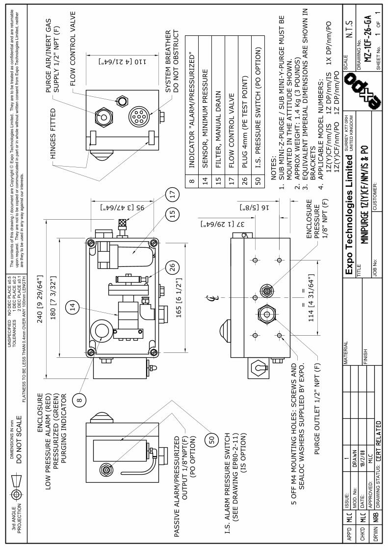
NO
TES:
SU
B M
INI-
Z-P
URG
E /
SU
B M
INI-
Y-PU
RG
E M
UST
BE
MO
UN
TED
IN
TH
E ATT
ITU
DE
SH
OW
N.
APP
RO
X W
EIG
HT:
1.4
Kg
(3 P
OU
ND
S)
EQU
IVALE
NT
IMPE
RIA
L D
IMEN
SIO
NS A
RE
SH
OW
N I
NBRACKET
SAPP
LICABLE
MO
DEL
NU
MBER
S:
1
Z(Y
)CF/
nm/I
S 1Z
DP/
nm/I
S 1
X D
P/nm
/PO
1
Z(Y
)CF/
nm/P
O 1
Z D
P/nm
/PO
8 14 15 17 26 50I.
S.
PRES
SU
RE
SW
ITCH
(PO
OPT
ION
)
PLU
G 4
mm
(PE
TES
T PO
INT)
FLO
W C
ON
TRO
L VALV
E
FILT
ER,
MAN
UAL
DRAIN
SEN
SO
R,
MIN
IMU
M P
RES
SU
RE
IND
ICATO
R "
ALA
RM
/PRES
SU
RIZ
ED"
HIN
GES
FIT
TED
C L
1. 2. 3. 4.

FLA
TNE
SS
TO
BE
LE
SS
TH
AN
0.4
mm
OV
ER
AN
Y 1
00m
m L
EN
GTH
UN
SP
EC
IFIE
DTO
LER
AN
CE
S
MA
TER
IAL
DR'W
N
APP'
D
CHK'
D
DR
AW
ING
STA
TUS
:A
PP
RO
VE
D:
MO
D. N
o:D
ATE
:
ISS
UE
:
3rd
AN
GLE
PR
OJE
CTI
ON
DIM
EN
SIO
NS
IN m
m
DO
NO
T S
CA
LE
Expo
Tec
hnol
ogie
s Li
mite
d
JOB
No:
FIN
ISH
TITL
E
CU
STO
ME
R:
SH
EE
T N
o.O
F
SU
RR
EY
TW
16 5
DB
UN
ITE
D K
ING
DO
M
DR
AW
ING
No.
SC
ALE
The
cont
ents
of t
his
draw
ing
/ doc
umen
t are
Cop
yrig
ht ã
Exp
o Te
chno
logi
es L
imite
d. T
hey
are
to b
e tre
ated
as
conf
iden
tial a
nd a
re re
turn
able
upon
requ
est.
The
y ar
e no
t to
be c
opie
d or
com
mun
icat
ed in
par
t or i
n w
hole
with
out w
ritte
n co
nsen
t fro
m E
xpo
Tech
nolo
gies
Lim
ited,
nei
ther
are
they
to b
e us
ed in
any
way
aga
inst
our
inte
rest
s.
NO
DE
C P
LAC
E ±
0.5
1 D
EC
PLA
CE
±0.
22
DE
C P
LAC
E ±
0.1
CDM
PAO PAO
PAO
DRAW
N12
/01/
04
1
XB
R-8T
D0-0
14Z(
Y)CF
& D
P/ss
QUIC
K INS
TALL
ATION
GUID
E
11
NTS
PAO
REL
IEF
VALV
E
SPAR
K
ARRE
STOR
PRES
SURI
ZED
ENCL
OSUR
E
SEL
ECT
ORIF
ICE
CONT
ROL
UNIT
Qui
ck I
nsta
llatio
n G
uide
FO
R C
F or
DP
syst
ems:
With
aid
of su
pplie
d m
ount
ing
tem
plat
e cu
t m
ount
ing
hole
s in
to t
he e
nclo
sure
.Fi
x M
iniP
urge
Con
trol
Uni
t to
enc
losu
re.
Fix
Rel
ief Val
ve t
o en
clos
ure.
For
CF
syst
ems
only
, se
lect
orific
e fo
r re
quired
pur
ge flo
w r
ate
and
fit in
to S
park
Arr
esto
r w
ith c
ircl
ip.
Fix
Spa
rk A
rres
tor
to e
nclo
sure
ens
urin
g th
at C
ontr
ol U
nit
and
Spa
rk A
rres
tor
Uni
t ar
e di
agon
ally
opp
osin
g.Con
nect
Out
put
optio
n, /
IS o
r /P
O a
s re
quired
, re
fer
to m
anua
l.Con
nect
isol
ated
air s
uppl
y to
Min
iPur
ge C
ontr
ol U
nit
Ensu
re e
nclo
sure
doo
r is
clo
sed
and
seal
ed fro
m le
aks.
Turn
on
air
supp
ly 6
0 ps
ig (
4 ba
rg).
Slo
wly
incr
ease
Flo
w C
ontr
ol V
alve
unt
il Ala
rm I
ndic
ator
tur
ns fro
m R
ED t
o G
REE
N.
Aft
er P
urge
tim
e ha
s be
en c
ompl
eted
pow
er c
an b
e ap
plie
d to
enc
losu
re.
All
quer
ies
refe
r to
man
ual f
or a
ssis
tanc
e in
the
first
inst
ance
.
NO
TE:
Spa
rk a
rres
tors
are
onl
y us
ed in
CF
syst
ems.
244
0608
/02/
08ML
C
1. 2. 3. 4. 5. 6. 7. 8. 9. 10.
11.
344
4218
/3/0
8ML
C
459
7925
/11/
13SM

Min
iPur
ge
35 [
1.38
"]
75 [2.95"]
240
[9 2
9/64
"]
77 [
3.03
"]
150
[59/
64"]
130 [5.12"]
ENCLO
SU
RE
PRES
SU
RE
1/8"
NPT
(F)
PU
RG
E O
UTL
ET 1
/2"N
PT(F
)
PURG
E AIR
/IN
ERT
GAS S
UPP
LY1/
2"N
PT(F
)
SYS
TEM
BREA
THER
-D
O N
OT
OBSTR
UCT
ENCLO
SU
RE
LOW
PRES
SU
RE
ALA
RM
(RED
)/PR
ESSU
RIZ
ED (
GREE
N)
PURG
ING
IN
DIC
ATO
RIN
DIC
ATO
R L
ABEL
180 [7 7/64"]
180
[7.0
9"]
MO
UN
TIN
G H
OLE
S
210 [8.27"]MOUNTING HOLES
230 [9.06"]
MO
UN
TIN
G B
AR
(SPE
CIA
L O
PTIO
N O
NLY
)
58 [
2.28
"]
28 [1.10"]
CABLE
EN
TRY
SU
ITABLE
FO
R M
20G
LAN
D (
GLA
ND
NO
T SU
PPLI
ED)
(IS O
PTIO
N)
6 [0
.24"
]
NO
TES:
THE
MIN
IPU
RG
E M
UST
BE
MO
UN
TED
WIT
H T
HE
PURG
E
OU
TLET
PO
INTI
NG
DO
WN
WARD
S.
APP
RO
X W
EIG
HT:
5 k
g (1
1 lb
s)
USE
DIR
ECT
MO
UN
TIN
G W
HER
EVER
PO
SSIB
LE.
WALL
MO
UN
TIN
G B
RACKET
S A
RE
OPT
ION
AL.
APP
LICABLE
MO
DEL
NU
MBER
S
1Z(Y
)CF/
ss/I
S 1
Z D
P/ss
/IS 1
X D
P/ss
/PO
1Z(Y
)CF/
ss/P
O 1Z
DP/
ss/P
O
2. 3.1.
85 [
3.35
"]
CER
TIFI
CATI
ON
LABEL
20 [
0.79
"]
65 [2.56"]
PASSIV
E ALA
RM
"PRES
URIZ
ED"
OU
TPU
T 1/
8"N
PT(F
)GAS S
UPP
LY(P
O O
PTIO
N)
4.
FLA
TNE
SS
TO
BE
LE
SS
TH
AN
0.4
mm
OV
ER
AN
Y 1
00m
m L
EN
GTH
UN
SP
EC
IFIE
DTO
LER
AN
CE
S
MA
TER
IAL
DR'W
N
APP'
D
CHK'
D
DR
AW
ING
STA
TUS
:A
PP
RO
VE
D:
MO
D. N
o:D
ATE
:
ISS
UE
:
3rd
AN
GLE
PR
OJE
CTI
ON
DIM
EN
SIO
NS
IN m
m
DO
NO
T S
CA
LE
Expo
Tec
hnol
ogie
s Li
mite
d
JOB
No:
FIN
ISH
TITL
E
CU
STO
ME
R:
SH
EE
T N
o.O
F
SU
RR
EY
TW
16 5
DB
UN
ITE
D K
ING
DO
M
DR
AW
ING
No.
SC
ALE
The
cont
ents
of t
his
draw
ing
/ doc
umen
t are
Cop
yrig
ht ã
Exp
o Te
chno
logi
es L
imite
d. T
hey
are
to b
e tre
ated
as
conf
iden
tial a
nd a
re re
turn
able
upon
requ
est.
The
y ar
e no
t to
be c
opie
d or
com
mun
icat
ed in
par
t or i
n w
hole
with
out w
ritte
n co
nsen
t fro
m E
xpo
Tech
nolo
gies
Lim
ited,
nei
ther
are
they
to b
e us
ed in
any
way
aga
inst
our
inte
rest
s.
NO
DE
C P
LAC
E ±
0.5
1 D
EC
PLA
CE
±0.
22
DE
C P
LAC
E ±
0.1
BRD
JTP
JTP
CERT
REL
ATED
JTP
DRAW
N03
/03/
1995
1
MZ
-1CF
-02-
GAMI
NIPU
RGE
1Z(Y
)CF&
DP/s
s/IS
& P
O
11
N.T.
S5
3955
01/0
3/05
HE
644
0608
/02/
08ML
C
759
5216
/10/
13SM

FLA
TNE
SS
TO
BE
LE
SS
TH
AN
0.4
mm
OV
ER
AN
Y 1
00m
m L
EN
GTH
UN
SP
EC
IFIE
DTO
LER
AN
CE
S
MA
TER
IAL
DR'W
N
APP'
D
CHK'
D
DR
AW
ING
STA
TUS
:A
PP
RO
VE
D:
MO
D. N
o:D
ATE
:
ISS
UE
:
3rd
AN
GLE
PR
OJE
CTI
ON
DIM
EN
SIO
NS
IN m
m
DO
NO
T S
CA
LE
Expo
Tec
hnol
ogie
s Li
mite
d
JOB
No:
FIN
ISH
TITL
E
CU
STO
ME
R:
SH
EE
T N
o.O
F
SU
RR
EY
KT7
0R
HU
NIT
ED
KIN
GD
OM
DR
AW
ING
No.
SC
ALE
The
cont
ents
of t
his
draw
ing
/ doc
umen
t are
Cop
yrig
ht ã
Exp
o Te
chno
logi
es L
imite
d. T
hey
are
to b
e tre
ated
as
conf
iden
tial a
nd a
re re
turn
able
upon
requ
est.
The
y ar
e no
t to
be c
opie
d or
com
mun
icat
ed in
par
t or i
n w
hole
with
out w
ritte
n co
nsen
t fro
m E
xpo
Tech
nolo
gies
Lim
ited,
nei
ther
are
they
to b
e us
ed in
any
way
aga
inst
our
inte
rest
s.
NO
DE
C P
LAC
E ±
0.5
1 D
EC
PLA
CE
±0.
22
DE
C P
LAC
E ±
0.1
PLU
G 4
mm
(PE
TE
ST
PO
INT)
FLO
W C
ON
TRO
L V
ALV
E
FILT
ER
, MA
NU
AL
DR
AIN
SE
NS
OR
, MIN
IMU
M P
RE
SS
UR
E
IND
ICA
TOR
"ALA
RM
/PR
ES
SU
RIZ
ED
"
BLA
CK
CO
LLA
R (P
LUG
GE
D)
14 15 17 267 8
DO
OR
INTE
RN
AL
EN
CLO
SU
RE
PR
ES
SU
RE
TES
T P
OIN
T
I.S. P
RE
SS
UR
E S
WIT
CH
(IS
OP
TIO
N O
NLY
)50
26
15
1714
78
50
NO
TES
:A
PP
LIC
AB
LE M
OD
EL
NU
MB
NE
RS
:1Z
(Y)C
F/ss
/IS1Z
(Y)C
F/ss
/PO
1Z D
P/s
s/IS
1Z D
P/s
s/P
O1X
DP
/ss/
PO
1.

12 3
FILT
ER
MIN
IMU
MP
RE
SS
UR
ES
EN
SO
RE
NC
LOS
UR
E P
RE
SS
UR
ETE
ST
PO
INT
(PLU
GG
ED
)
FLO
W C
ON
TRO
LV
ALV
E
MIN
IMU
M P
RE
SS
UR
E &
PU
RG
ING
IND
ICA
TOR
RE
D =
ALA
RM
GR
EE
N =
PR
ES
SU
RE
OK
PU
RG
E S
UP
PLY
AIR
OR
INE
RT
GA
S60
psi
g (4
bar
g) -
MA
X 1
15 P
SI (
8 ba
rg)
PA
SS
IVE
ALA
RM
/ P
RE
SS
UR
IZE
D" S
IGN
AL
60-1
15 P
SI (
4-8
barg
)
15
147
17
8
EN
CLO
SU
RE
PR
ES
SU
RE
PU
RG
E O
UTL
ET
TO P
RE
SS
UR
IZE
D E
NC
LOS
UR
E
ALA
RM
CO
NTA
CT
IS S
WIT
CH
50
/IS O
PTI
ON
/PO
OP
TIO
N
(OP
TIO
NA
L)
26
FLA
TNE
SS
TO
BE
LE
SS
TH
AN
0.4
mm
OV
ER
AN
Y 1
00m
m L
EN
GTH
UN
SP
EC
IFIE
DTO
LER
AN
CE
S
MA
TER
IAL
DR'W
N
APP'
D
CHK'
D
DR
AW
ING
STA
TUS
:A
PP
RO
VE
D:
MO
D. N
o:D
ATE
:
ISS
UE
:
3rd
AN
GLE
PR
OJE
CTI
ON
DIM
EN
SIO
NS
IN m
m
DO
NO
T S
CA
LE
Expo
Tec
hnol
ogie
s Li
mite
d
JOB
No:
FIN
ISH
TITL
E
CU
STO
ME
R:
SH
EE
T N
o.O
F
SU
RR
EY
KT7
0R
HU
NIT
ED
KIN
GD
OM
DR
AW
ING
No.
SC
ALE
The
cont
ents
of t
his
draw
ing
/ doc
umen
t are
Cop
yrig
ht ã
Exp
o Te
chno
logi
es L
imite
d. T
hey
are
to b
e tre
ated
as
conf
iden
tial a
nd a
re re
turn
able
upon
requ
est.
The
y ar
e no
t to
be c
opie
d or
com
mun
icat
ed in
par
t or i
n w
hole
with
out w
ritte
n co
nsen
t fro
m E
xpo
Tech
nolo
gies
Lim
ited,
nei
ther
are
they
to b
e us
ed in
any
way
aga
inst
our
inte
rest
s.
NO
DE
C P
LAC
E ±
0.5
1 D
EC
PLA
CE
±0.
22
DE
C P
LAC
E ±
0.1

(or s
uita
bly
prot
ecte
d ap
para
tus)
I.S.
Inte
rface
Uni
t
Pow
er s
uppl
y
or p
ower
con
tact
ors.
Non
-Haz
ardo
us L
ocat
ion O
utpu
ts e
.g. t
o re
lays
(or s
uita
bly
prot
ecte
d ap
para
tus)
I.S.
Inte
rface
Uni
t
Pow
er s
uppl
y
or p
ower
con
tact
ors.
Non
-Haz
ardo
us L
ocat
ion
Haz
ardo
us L
ocat
ion
Vm
ax =
30V
Imax
= 1
00m
A
Out
puts
e.g
. to
rela
ys
Fig
1a S
ingl
e ch
anne
l int
erfa
ce c
ircui
te.
g. "
Y"
or "
Z" P
ress
uriz
atio
n A
larm
circ
uit
e.g.
"X
" pr
essu
rizat
ion
Ala
rm &
Pow
er C
ontro
lFi
g 1b
Mul
ti-ch
anne
l int
erfa
ce c
ircui
t
Ci =
0
Li =
0
PC
B P
t# S
108/
*(*
= c
onfig
urat
ion)
devi
ceS
impl
e ap
para
tus
Gro
ups
A, B
, C, D
, E, F
and
GC
lass
I or
II,
Div
1 o
r 2
Not
es fo
r bot
h Fi
g 1a
and
Fig
1b
1 E
lect
rical
equ
ipm
ent c
onne
cted
to a
ssoc
iate
d ap
para
tus
shou
ld n
ot u
se o
r gen
erat
e m
ore
than
250
vol
ts2
Inst
alla
tion
shal
l be
in a
ccor
danc
e w
ith th
e m
anuf
actu
rer's
inst
ruct
ions
and
the
Nat
iona
l Ele
ctric
al C
ode
(AN
SI/N
FPA
70)
3 Fo
r gui
danc
e on
Inst
alla
tion
see
AN
SI/I
SA
RP
12.6
, (In
stal
latio
n of
IS In
stru
men
t Sys
tem
s in
Cla
ss I
Haz
ardo
us L
ocat
ions
)4
Voc
or V
t of a
ssoc
iate
d ap
para
tus
is le
ss th
an V
max
Isc
or I
t of a
ssoc
iate
d ap
para
tus
is le
ss th
an Im
ax C
i plu
s ca
paci
tanc
e of
inte
rcon
nect
ing
cabl
ing
is le
ss th
an C
a of
the
asso
ciat
ed a
ppar
atus
Li p
lus
indu
ctan
ce o
f int
erco
nnec
ting
cabl
ing
is le
ss th
an L
a of
the
asso
ciat
ed a
ppar
atus
5 "S
impl
e A
ppar
atus
" is
a d
evic
e th
at w
ill n
ot g
ener
ate
or s
tore
mor
e th
an 1
.2V
, 0.1
A, 2
5mW
or 2
0uJ
Min
iPur
ge: O
ptio
n C
ode
/ISM
iniP
urge
: Opt
ion
Cod
e /IS
Haz
ardo
us L
ocat
ion
Cla
ss I
or II
, D
iv 1
or 2
Gro
ups
A, B
, C, D
, E, F
and
G
Sim
ple
App
arat
us C
onne
ctio
n fo
r M
anua
l Ove
rrid
e Sw
itch
(dry
con
tact
)Vm
ax =
0V,
Im
ax =
0A,
Ci =
0,
Li =
0
Vm
ax =
30V
Imax
= 1
00m
ACi =
0 L
i = 0
6 Fo
r Gas
Gro
ups
A, B
per
mitt
ed Im
ax fo
r I.S
., fo
r V p
eak
= 30
V is
101
mA
A
ltern
ativ
ely:
For
Gas
Gro
up A
, B w
ith V
peak
= 1
9.2V
Imax
for I
.S. i
s 35
0mA
.
+ 1 2 0 M
REV
.M
OD
NUM
BER
APP
ROV
ED D
ATE
APP
ROV
ED
443
3013
/7/2
007
MLC
0550
7601
/11/
2010
AM
O
0652
9720
/07/
2011
AM
O
3rd
AN
GLE
PRO
JECTI
ON
DIM
ENSIO
NS I
N m
m
DO
NO
T SCALE
Exp
o Te
chno
logi
es L
imite
d
JOB N
o:
TITL
E
CU
STO
MER
:
SH
EET
No.
OF
1
SU
RR
EY
KT7
0R
HU
NIT
ED
KIN
GD
OM
DRAW
ING
No.
SCALE
The
cont
ents
of th
is d
raw
ing
/ do
cum
ent
are
Cop
yrig
ht ©
Exp
o Te
chno
logi
es L
imite
d. Th
ey a
re t
o be
tre
ated
as
conf
iden
tial
and
are
retu
rnab
le u
pon
requ
est.
Th
ey a
re n
ot t
o be
cop
ied
or c
omm
unic
ated
in p
art
or in
who
le w
ithou
t w
ritt
en c
onse
nt
from
Exp
o Te
chno
logi
es L
imite
d, n
eith
er a
re t
hey
to b
e us
ed in
any
way
aga
inst
our
inte
rest
s.
MIN
IPU
RG
E O
PTIO
N 'I
S'
EP80
-2-1
1
NTS
1
REV
: 06D
RAW
ING
STA
TUS:
APP
'DCH
K'D
DR'W
N
AM
OAM
OAM
O
13/0
7/20
07Cer
tifie
d
DRAW
N D
ATE
:TH
IS I
S A
CER
TIF
ICA
TIO
ND
OC
UM
EN
T.
A
NY
UN
AU
TH
OR
ISED
C
HA
NG
E I
NV
ALI
DA
TES
AP
PR
OV
AL.

FLA
TNE
SS
TO
BE
LE
SS
TH
AN
0.4
mm
OV
ER
AN
Y 1
00m
m L
EN
GTH
UN
SP
EC
IFIE
DTO
LER
AN
CE
S
MA
TER
IAL
DR'W
N
APP'
D
CHK'
D
DR
AW
ING
STA
TUS
:A
PP
RO
VE
D:
MO
D. N
o:D
ATE
:
ISS
UE
:
3rd
AN
GLE
PR
OJE
CTI
ON
DIM
EN
SIO
NS
IN m
m
DO
NO
T S
CA
LE
Expo
Tec
hnol
ogie
s Li
mite
d
JOB
No:
FIN
ISH
TITL
E
CU
STO
ME
R:
SH
EE
T N
o.O
F
SU
RR
EY
KT7
0R
HU
NIT
ED
KIN
GD
OM
DR
AW
ING
No.
SC
ALE
The
cont
ents
of t
his
draw
ing
/ doc
umen
t are
Cop
yrig
ht ã
Exp
o Te
chno
logi
es L
imite
d. T
hey
are
to b
e tre
ated
as
conf
iden
tial a
nd a
re re
turn
able
upon
requ
est.
The
y ar
e no
t to
be c
opie
d or
com
mun
icat
ed in
par
t or i
n w
hole
with
out w
ritte
n co
nsen
t fro
m E
xpo
Tech
nolo
gies
Lim
ited,
nei
ther
are
they
to b
e us
ed in
any
way
aga
inst
our
inte
rest
s.
NO
DE
C P
LAC
E ±
0.5
1 D
EC
PLA
CE
±0.
22
DE
C P
LAC
E ±
0.1
ø55
[2 5
/32"
]35
[1 3
/8"]
25 [1
"]
M25 x 1.5P
TO S
UIT
PA
NE
L TH
ICK
NE
SS
1.5
[1/1
6"] M
INIM
UM
9.5
[3/8
"] M
AX
IMU
M
SP
AR
K A
RR
ES
TOR
BO
DY
GA
SK
ET
OR
IFIC
E P
LATE
& C
IRC
LIP
(SE
E N
OTE
2) RE
TAIN
ING
NU
T
WA
SH
ER
PA
RT
SE
CTI
ON
TH
RU
SP
AR
K A
RR
ES
TOR
BO
DY
NO
TES
:
TO E
NS
UR
E E
FFE
CTI
VE
PU
RG
ING
TH
E S
PA
RK
AR
RE
STO
R S
HO
ULD
BE
LO
CA
TED
ON
TH
E P
RE
SS
UR
IZE
D E
NC
LOS
UR
E A
S F
AR
AW
AY
AS
PR
AC
TIC
AB
LE F
RO
M T
HE
PU
RG
E A
IR IN
LET.
FLO
W R
ATE
SE
LEC
TIO
N:
THE
FLO
W R
ATE
OF
THE
CO
NTI
NU
OU
S F
LOW
SY
STE
M M
AY
BE
CH
OS
EN
BY
TH
EU
SE
R B
Y S
ELE
CTI
NG
TH
E R
EQ
UIR
ED
OR
IFIC
E P
LATE
.FO
R R
AN
GE
OF
FLO
W R
ATE
S S
EE
TA
BLE
OF
VA
LUE
S O
PP
OS
ITE
.
AS
SE
MB
LY IN
STR
UC
TIO
NS
:
DE
CID
E U
PO
N T
HE
RE
QU
IRE
D F
LOW
RA
TE.
SE
LEC
T TH
E R
EQ
UIR
ED
OR
IFIC
E P
LATE
.IN
STA
LL T
HE
PLA
TE IN
TH
E S
PA
RK
AR
RE
STO
R B
OD
Y A
ND
RE
TAIN
WIT
H T
HE
CIR
CLI
P.
EX
PO
PA
RT
No.
SA
U25
RE
CO
MM
EN
DE
D M
OU
NTI
NG
HO
LE ø
26 [1
"]W
EIG
HT:
0.2
5kg
[0.5
5lb]
1 2 3 i ii iii
Nl/m
in =
NO
RM
AL
LITR
ES
/MIN
UTE
scfm
= S
TAN
DA
RD
CU
BIC
FE
ET/
MIN
UTE
* V
C =
VO
LUM
E C
HA
NG
ES
(BA
SE
D O
N 3
0min
PU
RG
E T
IME
)
1 2 3 4 5 6 7 8
Nl/m
in
10 25 40 65 90 135
180
225
scfm 0.4
0.9
1.4
2.3
3.2
4.8
6.4
8.0
ft³ (
4VC
*)
3.0
8.3
10.5
17.2 24 36 48 60
m³
(5V
C*)
0.06
0.15
0.24
0.39
0.54
0.81
1.08
1.35
PU
RG
E F
LOW
EN
CLO
SU
RE
VO
LUM
E
BA
SE
D O
N A
PU
RG
E S
UP
PLY
OF
4 ba
rg [6
0 ps
i]&
EN
CLO
SU
RE
PR
ES
SU
RE
OF
2.5
mba
rg [1
" WC
]O
RIF
ICE
PLA
TE N
o
SE
LEC
TIO
N O
F O
RIF
ICE
PLA
TE

FLA
TNE
SS
TO
BE
LE
SS
TH
AN
0.4
mm
OV
ER
AN
Y 1
00m
m L
EN
GTH
UN
SP
EC
IFIE
DTO
LER
AN
CE
S
MA
TER
IAL
DR'W
N
APP'
D
CHK'
D
DR
AW
ING
STA
TUS
:A
PP
RO
VE
D:
MO
D. N
o:D
ATE
:
ISS
UE
:
3rd
AN
GLE
PR
OJE
CTI
ON
DIM
EN
SIO
NS
IN m
m
DO
NO
T S
CA
LE
Expo
Tec
hnol
ogie
s Li
mite
d
JOB
No:
FIN
ISH
TITL
E
CU
STO
ME
R:
SH
EE
T N
o.O
F
SU
RR
EY
TW
16 5
DB
UN
ITE
D K
ING
DO
M
DR
AW
ING
No.
SC
ALE
The
cont
ents
of t
his
draw
ing
/ doc
umen
t are
Cop
yrig
ht ã
Exp
o Te
chno
logi
es L
imite
d. T
hey
are
to b
e tre
ated
as
conf
iden
tial a
nd a
re re
turn
able
upon
requ
est.
The
y ar
e no
t to
be c
opie
d or
com
mun
icat
ed in
par
t or i
n w
hole
with
out w
ritte
n co
nsen
t fro
m E
xpo
Tech
nolo
gies
Lim
ited,
nei
ther
are
they
to b
e us
ed in
any
way
aga
inst
our
inte
rest
s.
NO
DE
C P
LAC
E ±
0.5
1 D
EC
PLA
CE
±0.
22
DE
C P
LAC
E ±
0.1
PURG
E FL
OW
ENCLO
SU
RE
VO
LUM
E
BASED
ON
A P
URG
E SU
PPLY
OF
4 ba
rg [
60 p
si]
AN
D E
NCLO
SU
RE
PRES
SU
RE
OF
2.5
mba
rg [
1" W
C]
ORIF
ICE
PLATE
No
SEL
ECTI
ON
OF
ORIF
ICE
PLATE
FO
R C
F SYS
TEM
S
ft³
(4VC*)
scfm
Nl/
min
m³ (5
VC*)
120.
016
445
02.
7097
.513
336
52.
1975
.010
227
51.
6560
.08
122
51.
35
Nl/
min
=N
ORM
AL
LITR
ES/M
INU
TEsc
fm =
STA
ND
ARD
CU
BIC
FEE
T/M
INU
TE*
VC =
VO
LUM
E CH
AN
GES
(BASED
ON
30m
in P
URG
E TI
ME)
NO
TES:
WEI
GH
T: 0.
25kg
[0.
55lb
]
EXPO
PART
CO
DE
: M
SK-S
000-
020
TO E
NSU
RE
EFFE
CTI
VE
PURG
ING
TH
E SPA
RK A
RRES
TOR
SH
OU
LD B
E LO
CATE
D O
N T
HE
PRES
SU
RIZ
ED E
NCLO
SU
RE
AS
FAR A
WAY
AS P
RACTI
CABLE
FRO
M T
HE
PURG
E AIR
IN
LET.
RE
CO
MM
EN
DE
D M
OU
NTI
NG
HO
LE ø
41 [1
5 8" D
IA]
1. 2. 3.
(a)
(b)
(c)
ASSEM
BLY
IN
STR
UCTI
ON
S:
USE
THE
TABLE
ABO
VE
TO C
HO
OSE
THE
REQ
UIR
ED F
LOW
RATE
.
SEL
ECT
THE
REQ
UIR
ED O
RIF
ICE
PLATE
.
FIT
THE
ORIF
ICE
PLATE
IN
TH
E SPA
RK A
RRES
TOR B
OD
Y AN
D R
ETAIN
WIT
H T
HE
CIR
CLI
P.
AIR/INERT GAS EXHAUST
SPA
RK A
RRES
TOR B
OD
Y GASKET
M40
NU
T
ORIF
ICE
PLATE
AN
D C
IRCLI
P
4.
1.5
[1/1
6"]
MIN
IMU
M9.
5 [3
/8"]
MAXIM
UM
PAN
EL T
HIC
KN
ESS
17.5
[11
/16"
]60
[2
3/8"
]
19.5
[25
/32"
]
44 [1 23/32"]
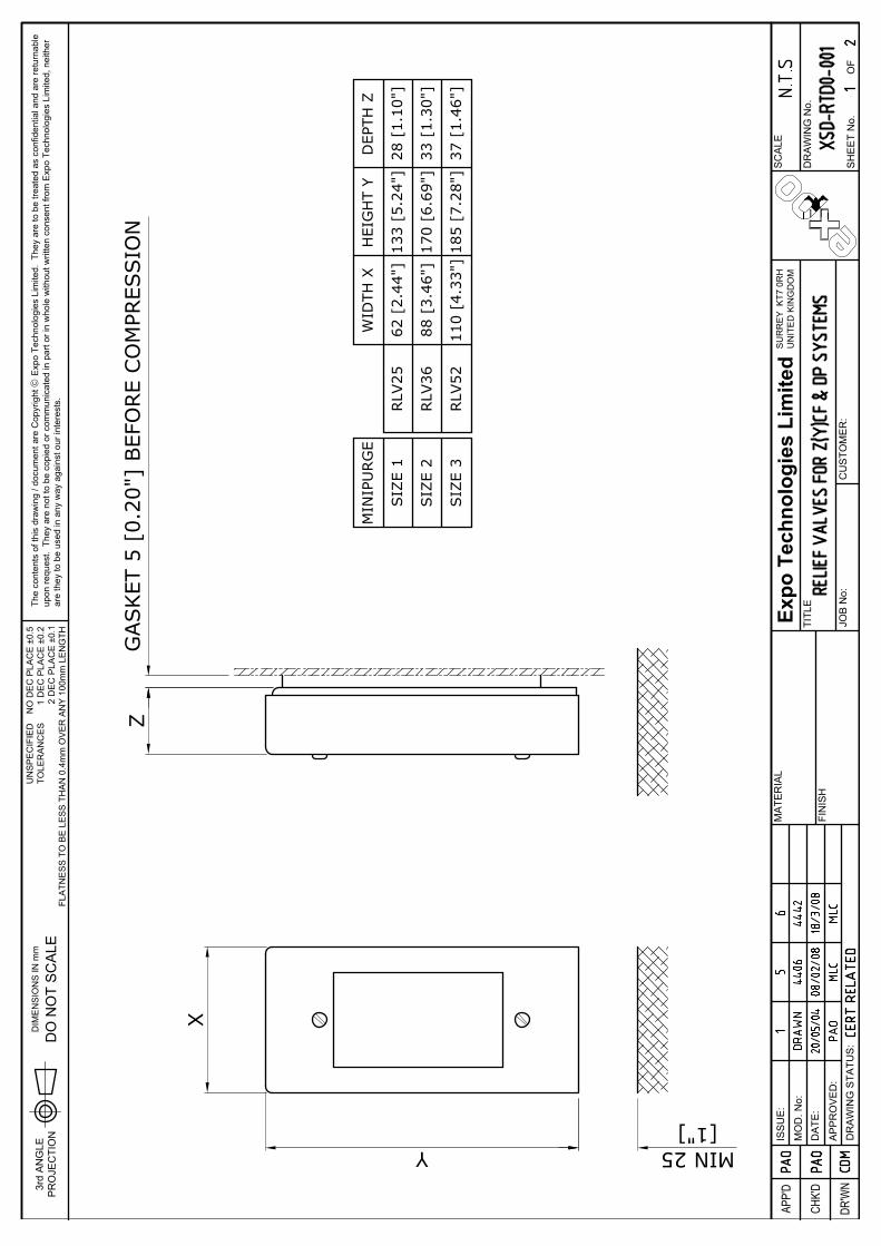
FLA
TNE
SS
TO
BE
LE
SS
TH
AN
0.4
mm
OV
ER
AN
Y 1
00m
m L
EN
GTH
UN
SP
EC
IFIE
DTO
LER
AN
CE
S
MA
TER
IAL
DR'W
N
APP'
D
CHK'
D
DR
AW
ING
STA
TUS
:A
PP
RO
VE
D:
MO
D. N
o:D
ATE
:
ISS
UE
:
3rd
AN
GLE
PR
OJE
CTI
ON
DIM
EN
SIO
NS
IN m
m
DO
NO
T S
CA
LE
Expo
Tec
hnol
ogie
s Li
mite
d
JOB
No:
FIN
ISH
TITL
E
CU
STO
ME
R:
SH
EE
T N
o.O
F
SU
RR
EY
KT7
0R
HU
NIT
ED
KIN
GD
OM
DR
AW
ING
No.
SC
ALE
The
cont
ents
of t
his
draw
ing
/ doc
umen
t are
Cop
yrig
ht ã
Exp
o Te
chno
logi
es L
imite
d. T
hey
are
to b
e tre
ated
as
conf
iden
tial a
nd a
re re
turn
able
upon
requ
est.
The
y ar
e no
t to
be c
opie
d or
com
mun
icat
ed in
par
t or i
n w
hole
with
out w
ritte
n co
nsen
t fro
m E
xpo
Tech
nolo
gies
Lim
ited,
nei
ther
are
they
to b
e us
ed in
any
way
aga
inst
our
inte
rest
s.
NO
DE
C P
LAC
E ±
0.5
1 D
EC
PLA
CE
±0.
22
DE
C P
LAC
E ±
0.1
Z
X
Y
GASKET
5 [
0.20
"] B
EFO
RE
CO
MPR
ESSIO
N
MIN
IPU
RG
E
SIZ
E 1
SIZ
E 2
SIZ
E 3
RLV
25
RLV
36
RLV
52
DEP
TH Z
28 [
1.10
"]
33 [
1.30
"]
37 [
1.46
"]
HEI
GH
T Y
133
[5.2
4"]
170
[6.6
9"]
185
[7.2
8"]
WID
TH X
62 [
2.44
"]
88 [
3.46
"]
110
[4.3
3"]
MIN 25[1"]

FLA
TNE
SS
TO
BE
LE
SS
TH
AN
0.4
mm
OV
ER
AN
Y 1
00m
m L
EN
GTH
UN
SP
EC
IFIE
DTO
LER
AN
CE
S
MA
TER
IAL
DR'W
N
APP'
D
CHK'
D
DR
AW
ING
STA
TUS
:A
PP
RO
VE
D:
MO
D. N
o:D
ATE
:
ISS
UE
:
3rd
AN
GLE
PR
OJE
CTI
ON
DIM
EN
SIO
NS
IN m
m
DO
NO
T S
CA
LE
Expo
Tec
hnol
ogie
s Li
mite
d
JOB
No:
FIN
ISH
TITL
E
CU
STO
ME
R:
SH
EE
T N
o.O
F
SU
RR
EY
KT7
0R
HU
NIT
ED
KIN
GD
OM
DR
AW
ING
No.
SC
ALE
The
cont
ents
of t
his
draw
ing
/ doc
umen
t are
Cop
yrig
ht ã
Exp
o Te
chno
logi
es L
imite
d. T
hey
are
to b
e tre
ated
as
conf
iden
tial a
nd a
re re
turn
able
upon
requ
est.
The
y ar
e no
t to
be c
opie
d or
com
mun
icat
ed in
par
t or i
n w
hole
with
out w
ritte
n co
nsen
t fro
m E
xpo
Tech
nolo
gies
Lim
ited,
nei
ther
are
they
to b
e us
ed in
any
way
aga
inst
our
inte
rest
s.
NO
DE
C P
LAC
E ±
0.5
1 D
EC
PLA
CE
±0.
22
DE
C P
LAC
E ±
0.1
= =
44[1
.73"
]
= =44
[1.73"]
= 64
[2.
52"]
=
= 64 [2.52"] =
= 76 [3.00"] =
= 76
[3.
00"]
=
46 [1.81"]
133 [5.24"]
= 62
[2.
44"]
=
RLV OU
TLIN
E
= 88
[3.
46"]
=
= 10
9 [4
.29"
] =
56 [2.20"]
170 [6.69"]
65 [2.56"]
185 [7.28"]
RLV OU
TLIN
E
RLV
25 C
UTO
UT
DET
AIL
'A'
DET
AIL
'B'
DET
AIL
'C'
RLV
36 C
UTO
UT
RLV
52 C
UTO
UT
HO
LE ø
52 -
0 +2 [
2" -
0 +0.
1 ]
4 H
OLE
Sø5
.5[7
/32"
]
4 H
OLE
Sø5
.5[7
/32"
]
HO
LE ø
36 -
0 +2
[1
1/2"
-0 +0.
1 ]
4 H
OLE
Sø5
.5[7
/32"
]
RLV OU
TLIN
E
HO
LE ø
25 -
0 +2
[1"
-0 +0.
1 ]

S:\QUALITY\CERTS\C-OF-C\SC004 Minipurge EU DoC Issue10.doc
EU-Declaration of Conformity
WithEuropeanDirectives
Issued under the sole responsibility of
Expo Technologies Ltd Unit 2, The Summit, Hanworth Road
Sunbury on Thames TW16 5DB, UK
This is to declare that “Purge Controllers: Sub-MiniPurge, MiniPurge, Super-MiniPurge, Super-MiniPurge 1800/3500/7000/7000X”
are manufactured in conformity with the following European Directives and standards:
Electromagnetic Compatibility Directive 2014/30/EU MiniPurge Systems with a /PO suffix in the type number are non-electrical and are outside the scope of the EMC Directive. MiniPurge Systems with suffices /PA or /IS incorporate one or more volt-free (“dry”) contacts which work in circuits specified by others. In normal operation these circuits are “benign” and no CE mark is appropriate. MiniPurge Systems with Electronic Timer (Option /ET) are designed to conform to the EMC Directive, in compliance with EN 61000-6-4:2007 and EN 61000-6-2:2005 (Intertek Report EM10048000). Low Voltage Directive 2014/35/EU MiniPurge Systems are intended for use in potentially explosive atmospheres (Hazardous Areas) and are therefore excluded from the Low Voltage Directive. Pressure Equipment Directive 2014/68/EU MiniPurge Systems are classified as not higher than category I under Article 13 of this Directive and intended for use in potentially explosive atmospheres (Hazardous Areas) and are therefore excluded from the Pressure Equipment Directive. MiniPurge Systems are covered under ATEX Directive 2014/34/EU. ATEX Directive 2014/34/EU Equipment for explosive atmospheres MiniPurge Systems are designed to conform to the ATEX Directive in fulfilment of the essential health and safety requirements set out in Annex II, and in compliance with: EN 60079-0: 2012 + A11:2013 EN 60079-2: 2014 MiniPurge Systems are certified by SIRA Certification Service, Hawarden Industrial Park, Hawarden CH5 3US, England, under EC Type-Examination Certificate SIRA 01ATEX1295X, in compliance with: EN 60079-0: 2012 EN 60079-2: 2014 According to the model, MiniPurge Systems are rated and shall be marked as follows:
MiniPurge, Type X & Type Y models Group II Category 2G & 2D II 2(2) GD
MiniPurge, Type Z models Group II Category 3G & 3D II 2(3) GD MiniPurge systems are manufactured under Production Quality Assurance Notification SIRA 99 ATEX M043, issued by SIRA Certification Service, Notified Body No 0518. Signed for and on behalf of Expo Technologies Ltd.,
John Paul de Beer Date 16/08/2017 Managing Director Confidential Assessment file reference SC004

[This Page Intentionally Left Blank]

[This Page Intentionally Left Blank]

[This Page Intentionally Left Blank]

Expo Technologies USAExpo Technologies Inc.
9140 Ravenna Road Unit #3Twinsburg,
OH 440878, USAT: +1 440 247 5314F: +1 330 487 0611
Expo Technologies UKExpo Technologies Ltd.
Unit 2 The Summit, Hanworth RoadSunbury-On-Thames,
TW16 5DB, UKT: +44 20 8398 8011F: +44 20 8398 8014
Expo Technologies ChinaQingdao Expo M&E Technologies Co. Ltd
329 Huashan Er LuJimo City, Qingdao,
266200 ChinaT: +86 532 8906 9858F: +86 532 8906 9858
www.expoworldwide.com