minimun equipment list - atr rev. 5
DESCRIPTION
Minimun Equipment List - ATR Rev. 5TRANSCRIPT

MINIMUM EQUIPMENT LIST ATR 42-500 / ATR 72-212A
This Minimum Equipment List was prepared using a copy of the DGAC MMEL ATR Revision: 3, Date: 31/May/2011 , thru Temporary Revision TR 05, Date: 05/April/2012. This document is applicable to the ATR 42-500 HK- 4747 MSN 526, HK-4748 MSN 522, HK-4806 MSN 513, HK-4827 MSN 532 and HK-4862 MSN 571, and the ATR 72-212A HK- 4828 MSN 521 and HK-4863 MSN 552.
Page INT-1
REVISION NO: 4 DATE: June 2012

Page: I Revision: 3 MINIMUM EQUIPMENT LIST Date: February 2012 ATR 42-500 / ATR 72-212A Table of Contents SYSTEM NO. SYSTEM PAGE
-- Cover INT-1 -- Table of Contents I -- List of Effective Normal Pages II -- Highlights of Change V -- Preamble VI -- Introduction XV -- ATA List XVI -- Glossary of Standard Nomenclature XVII 21 Air Conditioning 21-1 22 Auto Flight 22-1 23 Communications 23-1 24 Electrical Power 24-1 25 Equipment/Furnishings 25-1 26 Fire Protection 26-1 27 Flight Controls 27-1 28 Fuel 28-1 29 Hydraulic Power 29-1 30 Ice and Rain Protection 30-1 31 Indicating/Recording Systems 31-1 32 Landing Gear 32-1 33 Lights 33-1 34 Navigation 34-1 35 Oxygen 35-1 36 Pneumatic 36-1 52 Doors 52-1 56 Windows 56-1 61 Propellers 61-1 73 Engine Fuel and Control 73-1 74 Ignition 74-1 75 Air 75-1 77 Engine Indicating 77-1 79 Oil 79-1 APPENDIX 1 PBN (RNAV/RNP) Operations PBN-1

Page: II Revision: 5 MINIMUM EQUIPMENT LIST Date: December 2012 ATR 42-500 / ATR 72-212A List of Effective Normal Pages – LENP Cover Page INT-1 4 June 2012 Table of Contents I 3 February 2012 List of Effective Normal Pages II 5 December 2012 III 5 December 2012 IV 4 June 2012 Highlights of Change V 5 December 2012 Preamble VI 3 February 2012 VII 3 February 2012 VIII 3 February 2012 IX 3 February 2012 X 3 February 2012 XI 3 February 2012 XII 3 February 2012 XIII 3 February 2012 XIV 3 February 2012 Introduction XV 4 June 2012 ATA List XVI 3 February 2012 Glossary of Standard Nomenclature XVII 3 February 2 012 XVIII 3 February 2012 XIX 3 February 2012 XX 3 February 2012 21 21-1 3 February 2012 21-2 3 February 2012 21-3 3 February 2012 22 22-1 3 February 2012 22-2 3 February 2012 23 23-1 4 June 2012 23-2 4 June 2012 23-3 4 June 2012 23-4 3 February 2012 24 24-1 3 February 2012 24-2 3 February 2012 24-2A 3 February 2012 25 25-1 4 June 2012 25-2 4 June 2012 25-3 3 February 2012 25-4 4 June 2012 25-5
25-6 4 4
June 2012 June 2012
26 26-1 3 February 2012 26-2 4 June 2012
REVISED By NAME:_____________________ QUALITY CONTROL CHIEF SATENA
SIGNATURE
APPROVED By NAME:________________ UAEAC PMI SIGNATURE
NAME:________________ UAEAC POI SIGNATURE

Page: III Revision: 5 MINIMUM EQUIPMENT LIST Date: December 2012 ATR 42-500 / ATR 72-212A List of Effective Normal Pages – LENP 27 27-1
27-2 3 3
February 2012 February 2012
27-3 3 February 2012 27-3A 3 February 2012 28 28-1 3 February 2012 28-2 3 February 2012 29 29-1 3 February 2012 29-2 3 February 2012 30 30-1 3 February 2012 30-2 3 February 2012 30-3 3 February 2012 30-4 3 February 2012 31 31-1 4 June 2012 31-2 5 DECEMBER 2012 31-3 3 February 2012 31-4 3 February 2012 31-5 3 February 2012 32 32-1 3 February 2012 32-2 3 February 2012 33 33-1 3 February 2012 33-2 3 February 2012 33-3 4 June 2012 34 34-1 3 February 2012 34-2 3 February 2012 34-3 3 February 2012 34-4 3 February 2012 34-4A 3 February 2012 34-4B 3 February 2012 34-4C 3 February 2012 34-4D 3 February 2012 34-5 3 February 2012 35 35-1 4 June 2012 35-2 4 June 2012 36 36-1 3 February 2012 52 52-1 3 February 2012 52-2 3 February 2012 52-3 3 February 2012 52-4 3 February 2012 56 56-1
4 June 2012
REVISED By NAME:_____________________ QUALITY CONTROL CHIEF SATENA
SIGNATURE
APPROVED By NAME:________________ UAEAC PMI SIGNATURE
NAME:________________ UAEAC POI SIGNATURE

Page: IV Revision: 4 MINIMUM EQUIPMENT LIST Date: June 2012 ATR 42-500 / ATR 72-212A List of Effective Normal Pages – LENP 61
61-1 61-2 61-2A
3 3 3
February 2012 February 2012 February 2012
73 73-1 3 February 2012 73-2 3 February 2012 74 74-1 3 February 2012 75 75-1 3 February 2012 77 77-1 3 February 2012 79 79-1 3 February 2012 APPENDIX 1 PBN-1 4 June 2012
REVISED By NAME:_____________________ QUALITY CONTROL CHIEF SATENA
SIGNATURE
APPROVED By NAME:________________ UAEAC PMI SIGNATURE
NAME:________________ UAEAC POI SIGNATURE


Page: V Revision: 5 MINIMUM EQUIPMENT LIST Date: December 2012 ATR 42-500 / ATR 72-212A Highlights of Change REV DATE DESCRIPTION
0 August 2010 ORIGINAL ALL PAGES 1 July 2011 ALL PAGES REVISED
2 November 2011 MSN 513 INCLUDED, PAGES 23-1, 25-1, 25-2, 25-3
AND 25-4 REVISED 3 February 2012 MSN’s 532 AND 521 INCLUDED, ALL PAGES REVISED
4 June 2012
MSN’s 571 AND 552 INCLUDED, PAGES INT-1, II, III, IV, V, XV, 23-1, 23-2, 23-3, 25-1, 25-2,
25-4, 25-5, 25-6, 26-2, 31-1, 33-3, 35-1, 35-2, 56-1 AND PBN-1 REVISED.
5 December 2012 Change item 31-32-1 PAGES II, III, V, 31-2
REVISED

Page: VI Revision: 3 MINIMUM EQUIPMENT LIST Date: February 2012 ATR 42-500 / ATR 72-212A Preamble
GOALS and PRINCIPLE
I-1 – GOALS The UAEAC require that all equipment installed on a n aircraft in compliance with the Airworthiness Standards and the Operating Requirements must be operative. However, the Requir ements also permit the use of a Minimum Equipment List (MEL) where compliance with certain equipment requirements in not necessary in the inte rests of safety under all operating conditions. Experience has shown that with various levels of redundancy designed into aircraft, operation of every system or installed component may not be necessary when the r emaining operative equipment can provide an acceptable level of safety . The EASA MASTER MINIMUM EQUIPMENT LIST (MMEL), is supplied by the manufacturer ATR (the type certificate holder) TO I MPROVE AIRCRAFT UTILIZATION AND THEREBY PROVIDE MORE CONVENIENT AND ECONOMIC AIR TRANSPORTATION FOR THE PUBLIC. THE EASA MMEL INCLUD ES THOSE ITEMS OF EQUIPMENT RELATED TO AIRWORTHINESS AND OPERATING REQUIREMENTS AND OTHER ITEMS OF EQUIPMENT WHICH THE EASA FINDS MAY BE INOP ERATIVE AND YET MAINTAIN AN ACCEPTABLE LEVEL OF SAFETY BY APPROPRIATE CONDITIONS AND LIMITATIONS. The Individual Satena´s MEL must be su bmitted to the UAEAC for approval. The MMEL is the basis for development of individual Satena’s MEL, which take into consideration the Satena’s particular air craft equipment configuration and operational conditions. Equipment not required by the operation being conducted and equipment in excess o f UAEAC requirements are included in the MEL with appropriate conditions and limitations. Satena´s MEL may differ in format from the MMEL, BUT CANNOT BE LESS RESTRICTIVE THAN THE MMEL. The individual Satena’s MEL, WHEN APPROVED, permits operation of the aircraft with inoperative equipment. The MMEL MUST NOT BE USED AS A SATENA’S MEL because it does not take into account:
- Satena´s specific requirements, definitions, operat ions or regulations.
- Specific flight operations. - Equipment added or modified by Satena after manufac turer delivery
(e.g. Supplemental Type Certificate). I-2 – PRINCIPLE For the sake of brevity, the MEL does not include:
- Obviously required items such as wings, rudders, fl aps, engines, landing gear.
- Items which do not affect the airworthiness of the aircraft such as galley equipment, entertainment systems.

Page: VII Revision: 3 MINIMUM EQUIPMENT LIST Date: February 2012 ATR 42-500 / ATR 72-212A Preamble
- Passenger convenience items.
HOWEVER, IT IS IMPORTANT TO REMEMBER THAT ALL EQUIPMENT RELATED TO THE AIRWORTHINESS AND THE OPERATING REQUIREMENTS OF THE AIRCRAFT NOT LISTED IN THE MEL MUST BE OPERATIVE FOR EACH FLIGHT.
NOTE 1: Refer to AFM for dispatch without certain s tructural components
(chapter 7, Configuration Deviation List). NOTE 2: Refer to AFM for dispatch with several syst ems inoperative
(chapter 7.02.00, supplements). Suitable conditions and limitations in the form of placards, maintenance procedures, crew operating procedures and other res trictions as necessary are specified in the MEL to ensure that a n acceptable level of safety is maintained. The MEL is intended to permit operation with inoper ative items of equipment for a period of time until repairs can be accomplished. It is important that repairs be accomplished at the earli est opportunity. In order to maintain an acceptable level of safety and reliability the MEL establishes limitations on the duration of and cond itions for operation with inoperative equipment. The MEL provides for re lease of the aircraft for flight with inoperative equipment. Operators ar e to establish a controlled and sound rectification program includin g the parts, personnel, facilities, procedures and schedules to ensure timely rectification. When an item of equipment is discovered to be inope rative, it is reported by making an entry in the Aircraft Mainten ance Record/Logbook as prescribed by UAEAC. The item is then either rec tified or may be deferred per the MEL or other approval means accept able to the competent Authority prior to further operation. MEL condition s and limitations do not relieve the operator from determining that the aircraft is in condition for safe operation with items of equipmen t inoperative. Satena is responsible for exercising the necessary operational control to ensure that an acceptable level of safety is mai ntained and to evaluate the new operational capability of the airc raft. The exposure to additional failures during continued operation with inoperative systems or components must also be considered. Wherever pos sible account has been taken in this MEL of multiple inoperative item s. However, it is unlikely that all possible combinations of this nat ure have been accounted for. Therefore, when operating with multi ple inoperative items, the inter–relationships between those items and the effect on aircraft operation and crew workload must be consid ered. WHEN USING THE MEL, COMPLIANCE WITH THE STATED INTE NT OF THE PREAMBLE, DEFINITIONS AND THE CONDITIONS AND LIMITATIONS SPEC IFIED IN THE MEL IS REQUIRED.

Page: VIII Revision: 3 MINIMUM EQUIPMENT LIST Date: February 2012 ATR 42-500 / ATR 72-212A Preamble
GENERAL
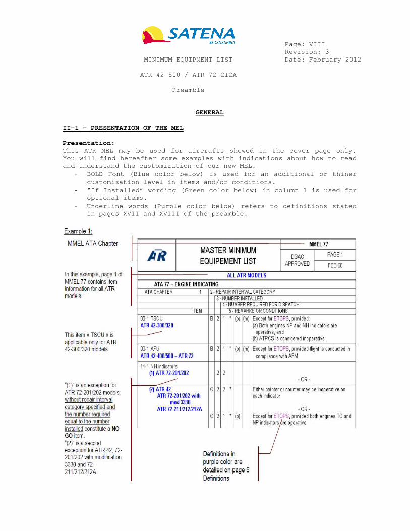
II-1 – PRESENTATION OF THE MEL Presentation: This ATR MEL may be used for aircrafts showed in th e cover page only. You will find hereafter some examples with indicati ons about how to read and understand the customization of our new MEL.
- BOLD Font (Blue color below) is used for an additio nal or thiner customization level in items and/or conditions.
- “If Installed” wording (Green color below) in colum n 1 is used for optional items.
- Underline words (Purple color below) refers to defi nitions stated in pages XVII and XVIII of the preamble.

Page: IX Revision: 3 MINIMUM EQUIPMENT LIST Date: February 2012 ATR 42-500 / ATR 72-212A Preamble
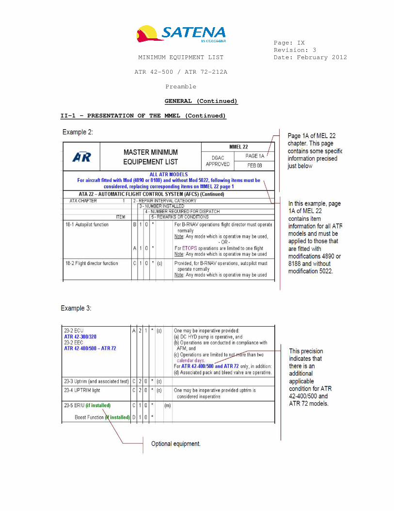
GENERAL (Continued)
II-1 – PRESENTATION OF THE MMEL (Continued)


Page: X Revision: 3 MINIMUM EQUIPMENT LIST Date: February 2012 ATR 42-500 / ATR 72-212A Preamble
GENERAL (Continued)
II-1 – PRESENTATION OF THE MMEL (Continued) Column 1: System and sequence numbers – Item Identifies the system by ATA classification and the item. It indicates the equipment, systems, components for which dispat ch conditions apply. An “ if installed ” annotation indicates that the listed item is not applicable to all models or configurations. It does not imply that the aircraft may be operated, in accordance with the MMEL, with the item removed, unless clearly indicated in the associated REMARKS or CONDITIONS column (5) of the MMEL. Column 2: Rectification interval For each applicable item, the rectification interva l column indicates the rectification interval category. Each category is defined according to the following EASA-MMEL/MEL definitions: - Category A No standard time interval is specified, however, it ems in this category shall be repaired in accordance with the conditions stated in REMARKS OR CONDITIONS (5) of the MMEL.
(i) Where a time period is specified in calendar days i t shall start at 00:01 on the calendar day following the da y of discovery.
(ii) Where a time period is specified in number of fligh t or flight hours, it shall start at the beginning of the next flight that follows the discovery.
- Category B Items in this category shall be repaired within thr ee (3) consecutive calendar days, excluding the day of discovery. For example, if it was recorded at 10 a.m. on January 26th, the three-day interval begins at midnight on January 26th, and ends at midnight the January 29th. - Category C Items in this category shall be repaired within ten (10) consecutive calendar days (240 hours), excluding the day of dis covery. - Category D Items in this category shall be repaired within one hundred and twenty (120) consecutive calendar days, excluding the day of discovery. Rectification interval extension policy: SATENA may use a procedure for the extension of the applicable rectification intervals B and C up to the same dura tion as specified in the MGM Annex L “MEL Management”.


Page: XI Revision: 3 MINIMUM EQUIPMENT LIST Date: February 2012 ATR 42-500 / ATR 72-212A Preamble
GENERAL (Continued)
II-1 – PRESENTATION OF THE MMEL (Continued) Column 3: Number installed Shows the number of installed components, it matche s with the type-certificated configuration of the aircraft. Column 4: Number required for dispatch Shows the minimum quantity of components which must be operative for a MEL dispatch, under the conditions listed in Column 5 (if any). Column 5: Remarks or exceptions Gives remarks or conditions linked to a MEL dispatc h. It indicates the suitable conditions and limitations in the form of placard, maintenance procedures, operational procedures and dispatch con ditions as necessary to ensure that an acceptable level of safety is mai ntained. - Asterisk “*” in column 5 requires inoperative components to be c learly placarded in the cockpit. - Operational and Maintenance Procedures: An inoperative equipment may refer to an operationa l (o) and/or maintenance procedure (m) in the Dispatch Deviation Guide (DDG), to ensure an acceptable level of safety. It is the operator’s responsibility to ensure that all the (o) and/or (m) refer to an appropriate operational and/or main tenance procedure, or to a procedure established by the operator and acce pted by the National Authority. Then the operator must ensure that these procedures are appropriately applied. Both (o) and (m) identifiers used singularly or in conjunction with each other, require that appropriate procedures be estab lished, published and complied with if flight is accomplished with the it em inoperative. Operational Procedures Task mark (o) in column 5 identifies an operational procedure whe n operating with the associated inoperative item. Ope rational procedures may require crew actions, limitations, performance penalties or crew awareness information to be taken into account. These procedures are normally carried out by qualif ied flight or cabin crew, but may be accomplished by other qualified, a pproved personnel. However the flight crew must always be informed of the applicable operational procedure prior to each flight under as sociated MMEL item. When flight situation occurs the operational proced ures must always be applied under the associated item (unless its perio dicity of application is clearly specified in Column 5).

Page: XII Revision: 3 MINIMUM EQUIPMENT LIST Date: February 2012 ATR 42-500 / ATR 72-212A Preamble
GENERAL (Continued)
II-1 – PRESENTATION OF THE MMEL (Continued) Maintenance Procedures Task mark (m) in column 5 identifies a maintenance procedure. The se procedures are normally carried out by maintenance personnel, but some elementary maintenance tasks may be accomplished by crew members or other qualified, approved personnel. Flight crew ca n accomplish some of these elementary (m) procedures but it remains the responsibility of the operator and under its national authority approval. However it is recommended that maintenance personne l accomplish procedures that require specialized knowledge, skil ls, or the use of tools and test equipment. The maintenance procedure s must always be performed one time before the flight under the asso ciated item and, if applicable, must be repeated at the interval specif ied in the Column 5.
- Different exceptions may be required for dispatch. They will be separated by “-OR–“ and identified by (1), (2), (3) in column 1.
- Different conditions may be required for dispatch. They will be identified by (a), (b), (c), … and separated by an “and”.
References - Another source of information must be reviewed an d associated restrictions, and/or procedures must be applied (e. g. “Refer to AFM…”). - Another ATA chapter of the MMEL must be reviewed, in order to determine the applicable item. The repair interval category the most restrictive must be applied. - References are introduced to assist the Operator in complying with MMEL requirements. However, as indicated in the PRE AMBLE, the Operator is still responsible for determining the applicable interrelationships and associated requirements.

Page: XIII Revision: 3 MINIMUM EQUIPMENT LIST Date: February 2012 ATR 42-500 / ATR 72-212A Preamble
GENERAL (Continued)
II-2 – DEFINITIONS - Inoperative : any time a system and/or component malfunctions t o the extent that it does not accomplish its intended pur pose and/or is not consistently functioning within its designed operat ing limit(s) or tolerance(s). - Considered Inoperative : must be treated as “inoperative”. Therefore the “considered inoperative” MEL item must also be recorded in the Technical log and the associated dispatch exception s must be applied, in addition to any applicable (o) and (m) procedure. T he shorter rectification interval, between the initial inopera tive item and the “considered inoperative” item, should be applied. - Day of discovery : The calendar day that the failure has been record ed in the aircraft maintenance record/logbook. - As required by regulation : The listed item must comply with applicable operational regulation. Operators may refer to the ATC regulation, and/or some local (airport) regulation. - Extended overwater flight : Refer to Chapter 2 of the UAEAC RAC item 4.2.3.2. - Flight : is defined as the period of time that begins the moment at which an aircraft begins to move by its own means i n preparation for take off, continues during take off and the applica ble flight phases, and ends when the aircraft lands and comes to a com plete stop in its parking area. - Ferry Flight : non-revenue flight with necessary flight crewmemb er to conduct a ferry flight. - Calendar days : Some MEL items are assigned a time interval in “d ays” in REMARKS OR CONDITIONS column 5. “Days” must be c onsidered as “calendar days”, not including the calendar day tha t the failure was recorded. - VMC flight conditions : atmospheric environment allows the flight to proceed under the Visual Meteorological Conditions applicable to the flight. - Icing conditions : Visible moisture in any form is present, and OAT on ground and for take off is at or below 5° or when T AT in flight is at or below 7°. Refer to the AFM 2-06.


Page: XIV Revision: 3 MINIMUM EQUIPMENT LIST Date: February 2012 ATR 42-500 / ATR 72-212A Preamble
GENERAL (Continued)
II-2 – DEFINITIONS (Continued) - Inflammable or Combustible material : material that can catch fire and burn. Where loading of inflammable or combustible m aterial is prohibited, no material may be loaded except the fo llowing: cargo handling equipment, flyaway kits (excluding e.g. ca ns of hydraulic fluid, cleaning solvents, batteries, chemical gener ators, etc) and in-flight service material (return catering-only close d catering trolleys/boxes, no newspaper, no alcohol or duty fr ee goods). - CAT 2 Automatic approach : The required equipment are listed in the AFM 7-01.03.


Page: XV Revision: 4 MINIMUM EQUIPMENT LIST Date: June 2012 ATR 42-500 / ATR 72-212A Introduction In compliance with RAC 4.2.2.7 and 4.5.9.3, a Minim um Equipment List (MEL) is published for each type of aircraft in sch eduled service. The MEL is used to determine whether an aircraft may co ntinue beyond a point of landing with a given airworthiness item out of s ervice. The design intent of the Minimum Equipment List is to allow dispatch with redundant components or items inoperative prov ided they occur in non-related systems. It must be determined prior to dispatch the net effect of multiple discrepancies to assure they do not accumulatively: (a) result in a non-acceptable level of airworthine ss, and (b) result in an undue increase in crew workload. Good judgment s hould be exercised by the users of this MEL to always assure safety exist s in all phases of flight. NOTE: To extent practical, placards should be locat ed adjacent to the control or indicator for the item affected; however , unless otherwise specified, placard wording and location will be det ermine by the operator. Every item MEL who could be deferred and who does n ot include procedures for operations and maintenance presents the form an d location of the placard below in the procedures section. Each holder of the manual as included in the distri bution list is responsible for updating and controlling MEL based on the List of Effective Normal Pages (LENP) provided. Request for MEL changes:
- Quality Director or his designee in coordination wi th Operation Director or his designee is responsible for providi ng the MEL/CDL/DDPM contents in this section of the manual . Request for changes, additions, or clarifications should be dir ected to obtain UAEAC approval.
- A vertical bar (change bar) in the margin indicates a change, addition or deletion in the adjacent text for the c urrent revision of that page only. The change bar is dropped at the next revision of the manual.
Manual distribution list:
- UAEAC. - Quality Director. - Operations Director. - Technical Information Point (PIT). - Inspectors Office. - Each ATR 42 and ATR 72 aircraft.

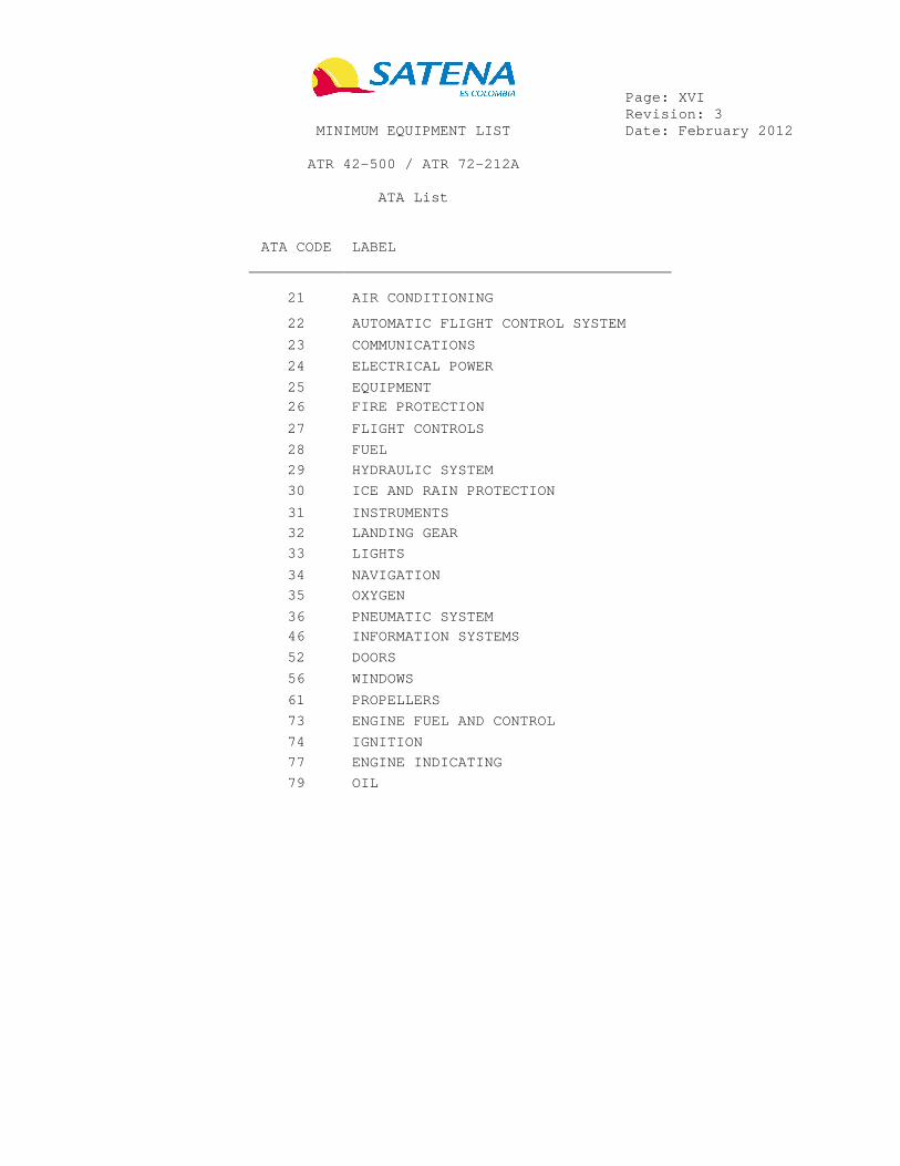
Page: XVI Revision: 3 MINIMUM EQUIPMENT LIST Date: February 2012 ATR 42-500 / ATR 72-212A ATA List
ATA CODE LABEL
21
AIR CONDITIONING
22 AUTOMATIC FLIGHT CONTROL SYSTEM
23 COMMUNICATIONS
24 ELECTRICAL POWER
25 EQUIPMENT
26 FIRE PROTECTION
27 FLIGHT CONTROLS
28 FUEL
29 HYDRAULIC SYSTEM
30 ICE AND RAIN PROTECTION
31 INSTRUMENTS
32 LANDING GEAR
33 LIGHTS
34 NAVIGATION
35 OXYGEN
36 PNEUMATIC SYSTEM
46 INFORMATION SYSTEMS
52 DOORS
56 WINDOWS
61 PROPELLERS
73 ENGINE FUEL AND CONTROL
74 IGNITION
77 ENGINE INDICATING
79 OIL

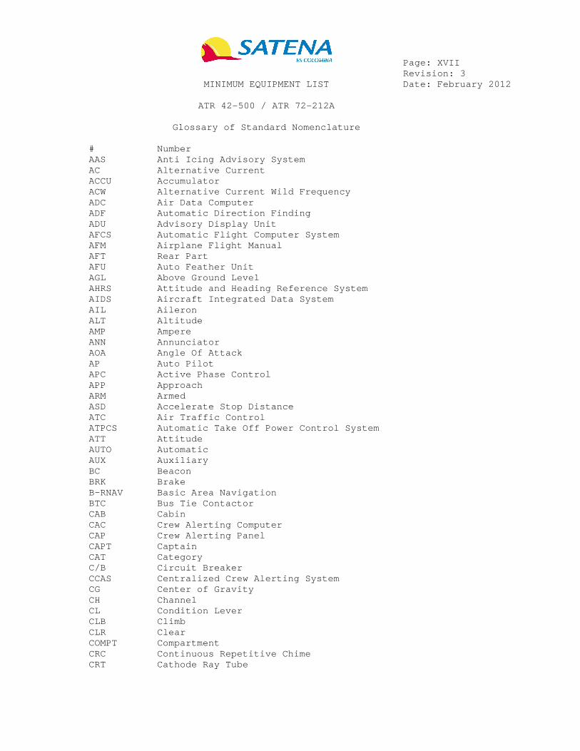
Page: XVII Revision: 3 MINIMUM EQUIPMENT LIST Date: February 2012 ATR 42-500 / ATR 72-212A Glossary of Standard Nomenclature # Number AAS Anti Icing Advisory System AC Alternative Current ACCU Accumulator ACW Alternative Current Wild Frequency ADC Air Data Computer ADF Automatic Direction Finding ADU Advisory Display Unit AFCS Automatic Flight Computer System AFM Airplane Flight Manual AFT Rear Part AFU Auto Feather Unit AGL Above Ground Level AHRS Attitude and Heading Reference System AIDS Aircraft Integrated Data System AIL Aileron ALT Altitude AMP Ampere ANN Annunciator AOA Angle Of Attack AP Auto Pilot APC Active Phase Control APP Approach ARM Armed ASD Accelerate Stop Distance ATC Air Traffic Control ATPCS Automatic Take Off Power Control System ATT Attitude AUTO Automatic AUX Auxiliary BC Beacon BRK Brake B-RNAV Basic Area Navigation BTC Bus Tie Contactor CAB Cabin CAC Crew Alerting Computer CAP Crew Alerting Panel CAPT Captain CAT Category C/B Circuit Breaker CCAS Centralized Crew Alerting System CG Center of Gravity CH Channel CL Condition Lever CLB Climb CLR Clear COMPT Compartment CRC Continuous Repetitive Chime CRT Cathode Ray Tube

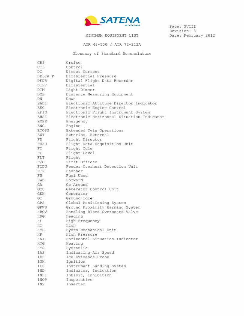
Page: XVIII Revision: 3 MINIMUM EQUIPMENT LIST Date: February 2012 ATR 42-500 / ATR 72-212A Glossary of Standard Nomenclature CRZ Cruise CTL Control DC Direct Current DELTA P Differential Pressure DFDR Digital Flight Data Recorder DIFF Differential DIM Light Dimmer DME Distance Measuring Equipment DN Down EADI Electronic Attitude Director Indicator EEC Electronic Engine Control EFIS Electronic Flight Instrument System EHSI Electronic Horizontal Situation Indicator EMER Emergency ENG Engine ETOPS Extended Twin Operations EXT Exterior, External FD Flight Director FDAU Flight Data Acquisition Unit FI Flight Idle FL Flight Level FLT Flight F/O First Officer FODU Feeder Overheat Detection Unit FTR Feather FU Fuel Used FWD Forward GA Go Around GCU Generator Control Unit GEN Generator GI Ground Idle GPS Global Positioning System GPWS Ground Proximity Warning System HBOV Handling Bleed Overboard Valve HDG Heading HF High Frequency HI High HMU Hydro Mechanical Unit HP High Pressure HSI Horizontal Situation Indicator HTG Heating HYD Hydraulic IAS Indicating Air Speed IEP Ice Evidence Probe IGN Ignition ILS Instrument Landing System IND Indicator, Indication INHI Inhibit, Inhibition INOP Inoperative INV Inverter

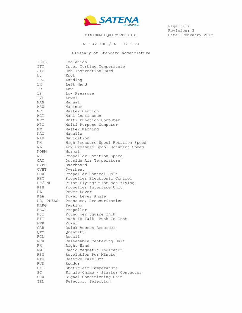
Page: XIX Revision: 3 MINIMUM EQUIPMENT LIST Date: February 2012 ATR 42-500 / ATR 72-212A Glossary of Standard Nomenclature ISOL Isolation ITT Inter Turbine Temperature JIC Job Instruction Card kt Knot LDG Landing LH Left Hand LO Low LP Low Pressure LVL Level MAN Manual MAX Maximum MC Master Caution MCT Maxi Continuous MFC Multi Function Computer MPC Multi Purpose Computer MW Master Warning NAC Nacelle NAV Navigation NH High Pressure Spool Rotation Speed NL Low Pressure Spool Rotation Speed NORM Normal NP Propeller Rotation Speed OAT Outside Air Temperature OVBD Overboard OVHT Overheat PCU Propeller Control Unit PEC Propeller Electronic Control PF/PNF Pilot Flying/Pilot non flying PIU Propeller Interface Unit PL Power Lever PLA Power Lever Angle PR, PRESS Pressure, Pressurization PRKG Parking PROP Propeller PSI Pound per Square Inch PTT Push To Talk, Push To Test PWR Power QAR Quick Access Recorder QTY Quantity RCL Recall RCU Releasable Centering Unit RH Right Hand RMI Radio Magnetic Indicator RPM Revolution Per Minute RTO Reserve Take Off RUD Rudder SAT Static Air Temperature SC Single Chime / Starter Contactor SCU Signal Conditioning Unit SEL Selector, Selection

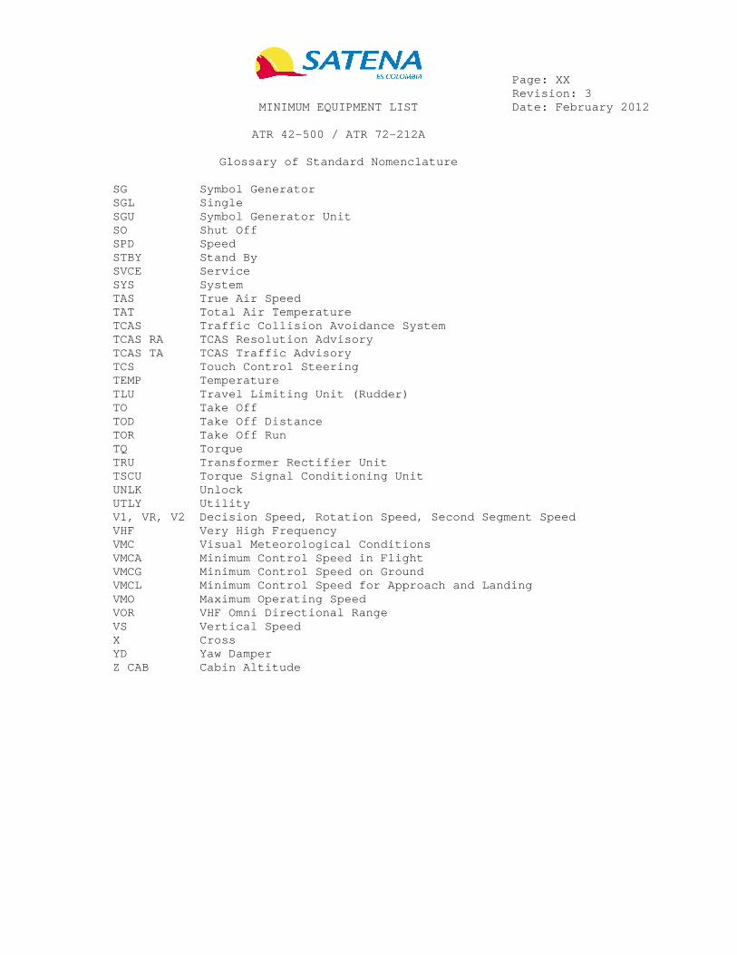
Page: XX Revision: 3 MINIMUM EQUIPMENT LIST Date: February 2012 ATR 42-500 / ATR 72-212A Glossary of Standard Nomenclature SG Symbol Generator SGL Single SGU Symbol Generator Unit SO Shut Off SPD Speed STBY Stand By SVCE Service SYS System TAS True Air Speed TAT Total Air Temperature TCAS Traffic Collision Avoidance System TCAS RA TCAS Resolution Advisory TCAS TA TCAS Traffic Advisory TCS Touch Control Steering TEMP Temperature TLU Travel Limiting Unit (Rudder) TO Take Off TOD Take Off Distance TOR Take Off Run TQ Torque TRU Transformer Rectifier Unit TSCU Torque Signal Conditioning Unit UNLK Unlock UTLY Utility V1, VR, V2 Decision Speed, Rotation Speed, Second Segment Speed VHF Very High Frequency VMC Visual Meteorological Conditions VMCA Minimum Control Speed in Flight VMCG Minimum Control Speed on Ground VMCL Minimum Control Speed for Approach and Landi ng VMO Maximum Operating Speed VOR VHF Omni Directional Range VS Vertical Speed X Cross YD Yaw Damper Z CAB Cabin Altitude


MINIMUM EQUIPMENT LIST
AIRCRAFT: REVISION NO : 3 PAGE:
ATR 42-500 / ATR 72-212A DATE: February 2012 21-1
SYSTEM & 1. SEQUENCE ITEM NUMBER
2. NUMBER INSTALLED
3. NUMBER REQUIRED FOR DISPATCH
21 – AIR CONDITIONING
4. REMARKS OR EXCEPTIONS
10-1 Flow Selector C 1 0 * Provided one mode (NORM or HIGH) is operative and used Note : some smoke procedures request to select air flow HIGH. Nevertheless associated procedures efficiency has been demonstrated with air flow NORM
22-1 Recirculation Fan C 2 0 * 23-1 Overboard Valve C 1 1 * (O)Automatic mode may be inoperative
provided manual mode is checked operative prior to each departure and flight is conducted in order to maintain ∆P ≤ 1 PSI
- OR - C 1 0 * (M)May be inoperative provided it is
deactivated, and extended overwater flight is prohibited, and flight level is limited to FL170
23-2 Underfloor Valve C 1 0 * (O)May be inoperative in closed
position provided exhaust mode is selected OVBD, and extended overwater flight is prohibited and flight level is limited to FL170
23-3 Extract Fan
(1) Passenger Configuration
C 1 0 * (O) May be inoperative provided exhaust mode is selected OVBD, and extended overwater flight is prohibited, and flight level is limited to FL170
- OR - C 1 1 * High speed may be inoperative 30-1 Pressurization
System C 1 0 (O)(M)The pressurization system
(automatic and/or manual modes) may be inoperative for a non pressurized flight provided:
(a) Extended overwater flight is prohibited.
31-1 Automatic Pressurization Control
C 1 0 * (O)May be inoperative, for a pressurized flight, provided:
(a) Manual pressurization is operative, and
(b) ALT, RATE and DIFF indications are operative

MINIMUM EQUIPMENT LIST
AIRCRAFT: REVISION NO : 3 PAGE:
ATR 42-500 / ATR 72-212A DATE: February 2012 21-2
SYSTEM & 1. SEQUENCE ITEM NUMBER
2. NUMBER INSTALLED
3. NUMBER REQUIRED FOR DISPATCH
21 - AIR CONDITIONING
4. REMARKS OR EXCEPTIONS
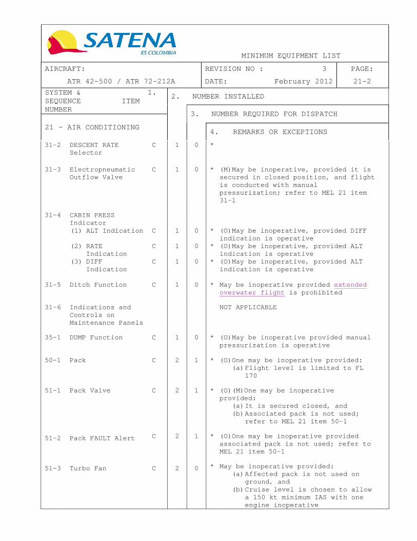
31-2 DESCENT RATE Selector
C 1 0 *
31-3 Electropneumatic
Outflow Valve C 1 0 * (M)May be inoperative, provided it is
secured in closed position, and flight is conducted with manual pressurization; refer to MEL 21 item 31-1
31-4 CABIN PRESS
Indicator
(1) ALT Indication C 1 0 * (O)May be inoperative, provided DIFF indication is operative
(2) RATE Indication
C 1 0 * (O)May be inoperative, provided ALT indication is operative
(3) DIFF Indication
C 1 0 * (O)May be inoperative, provided ALT indication is operative
31-5 Ditch Function
C 1 0 * May be inoperative provided extended
overwater flight is prohibited
31-6 Indications and
Controls on Maintenance Panels
NOT APPLICABLE
35-1 DUMP Function C 1 0 * (O)May be inoperative provided manual
pressurization is operative
50-1 Pack C 2 1 * (O)One may be inoperative provided:
(a) Flight level is limited to FL 170
51-1 Pack Valve C 2 1 * (O)(M)One may be inoperative
provided: (a) It is secured closed, and (b) Associated pack is not used;
refer to MEL 21 item 50-1
51-2 Pack FAULT Alert C 2 1 * (O)One may be inoperative provided associated pack is not used; refer to MEL 21 item 50-1
51-3 Turbo Fan C 2 0 * May be inoperative provided: (a) Affected pack is not used on
ground, and (b) Cruise level is chosen to allow
a 150 kt minimum IAS with one engine inoperative

MINIMUM EQUIPMENT LIST
AIRCRAFT: REVISION NO : 3 PAGE:
ATR 42-500 / ATR 72-212A DATE: February 2012 21-3
SYSTEM & 1. SEQUENCE ITEM NUMBER
2. NUMBER INSTALLED
3. NUMBER REQUIRED FOR DISPATCH
21 - AIR CONDITIONING
4. REMARKS OR EXCEPTIONS
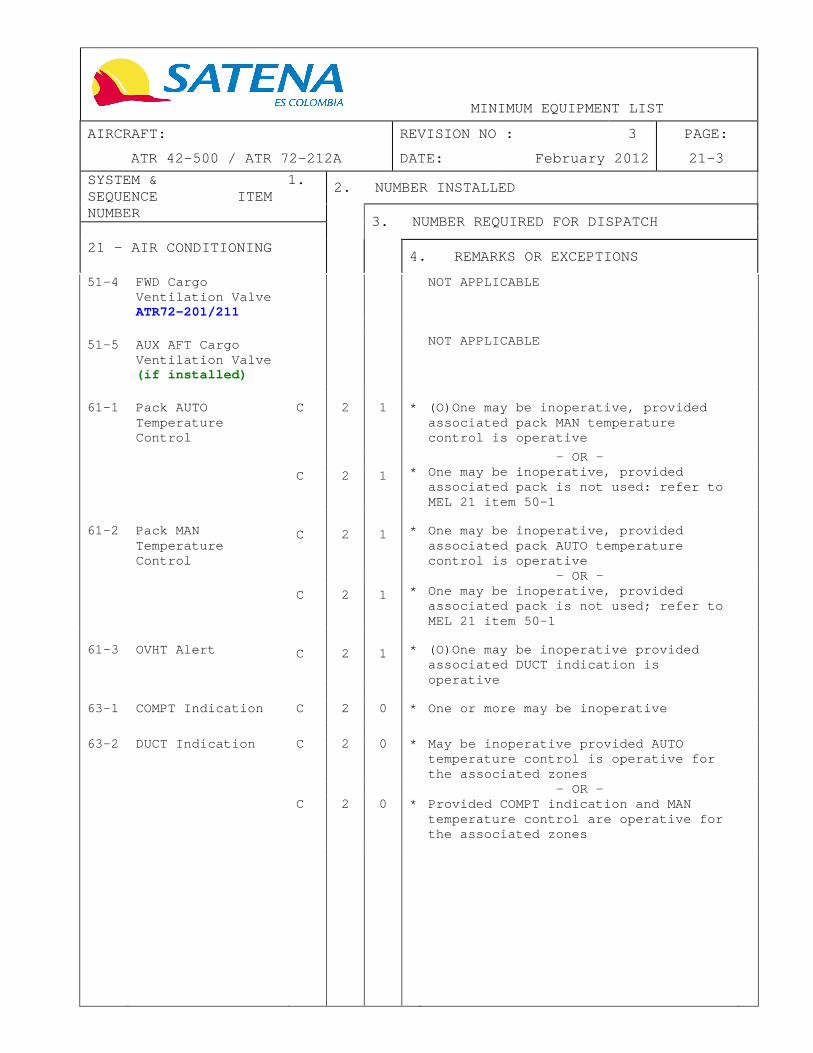
51-4 FWD Cargo Ventilation Valve ATR72-201/211
NOT APPLICABLE
51-5 AUX AFT Cargo Ventilation Valve (if installed)
NOT APPLICABLE
61-1 Pack AUTO
Temperature Control
C 2 1 * (O)One may be inoperative, provided associated pack MAN temperature control is operative
- OR -
C 2 1 * One may be inoperative, provided associated pack is not used: refer to MEL 21 item 50-1
61-2 Pack MAN
Temperature Control
C 2 1 * One may be inoperative, provided associated pack AUTO temperature control is operative
- OR -
C 2 1 * One may be inoperative, provided associated pack is not used; refer to MEL 21 item 50-1
61-3 OVHT Alert C 2 1 * (O)One may be inoperative provided
associated DUCT indication is operative
63-1 COMPT Indication C 2 0 * One or more may be inoperative 63-2 DUCT Indication C 2 0 * May be inoperative provided AUTO
temperature control is operative for the associated zones
- OR - C 2 0 * Provided COMPT indication and MAN
temperature control are operative for the associated zones


MINIMUM EQUIPMENT LIST
AIRCRAFT: REVISION NO : 3 PAGE:
ATR 42-500 / ATR 72-212A DATE: February 2012 22-1
SYSTEM & 1. SEQUENCE ITEM NUMBER
2. NUMBER INSTALLED
3. NUMBER REQUIRED FOR DISPATCH
22 - AUTOMATIC FLIGHT CONTROL SYSTEM (AFCS)
4. REMARKS OR EXCEPTIONS
15-1 Advisory Display Unit (ADU)
A 1 0 * (O)May be inoperative provided: (a) Both mode annunciators (on
EADI) are operative, and (b) Flight director only is used,
and (c) ALT SEL is not used, and (d) Operations are limited to not
more than two calendar days
16-1 Pitch Wheel C 1 0 * May be inoperative provided one TCS is
operative
16-2 Touch Control
Steering (TCS) C 2 0 * (O)One or both may be inoperative
16-3 Coupling Function
Pushbutton C 1 0 * (O)May be inoperative provided the
Pilot Flying is on the selected side
16-4 Autopilot Quick
Disconnect (Quick Release Control)
C 2 1 * (M)One may be inoperative provided the Pilot Flying side instrument is operative
- OR - B 2 0 * One or both may be inoperative
provided autopilot is considered inoperative and not used; refer to MEL 22 item 18-1
18-1 Autopilot Function B 1 0 * Any mode which is operative may be
used Note: RNAV/RNP associated item; refer to APPENDIX 1
18-2 Flight Director
Function C 1 0 * (O)Any mode which is operative may be
used Note: RNAV/RNP associated item; refer to APPENDIX 1
18-3 Yaw Damper
Function C 1 0 * May be inoperative provided RCU is
operative
- OR - A 1 0 * (O)May be inoperative provided
operations are limited to not more than two flights
36-1 Mode Annunciator
(EADI) C 2 0 *

MINIMUM EQUIPMENT LIST
AIRCRAFT: REVISION NO : 3 PAGE:
ATR 42-500 / ATR 72-212A DATE: February 2012 22-2
SYSTEM & 1. SEQUENCE ITEM NUMBER
2. NUMBER INSTALLED
3. NUMBER REQUIRED FOR DISPATCH
22 - AUTOMATIC FLIGHT CONTROL SYSTEM (AFCS)
4. REMARKS OR EXCEPTIONS
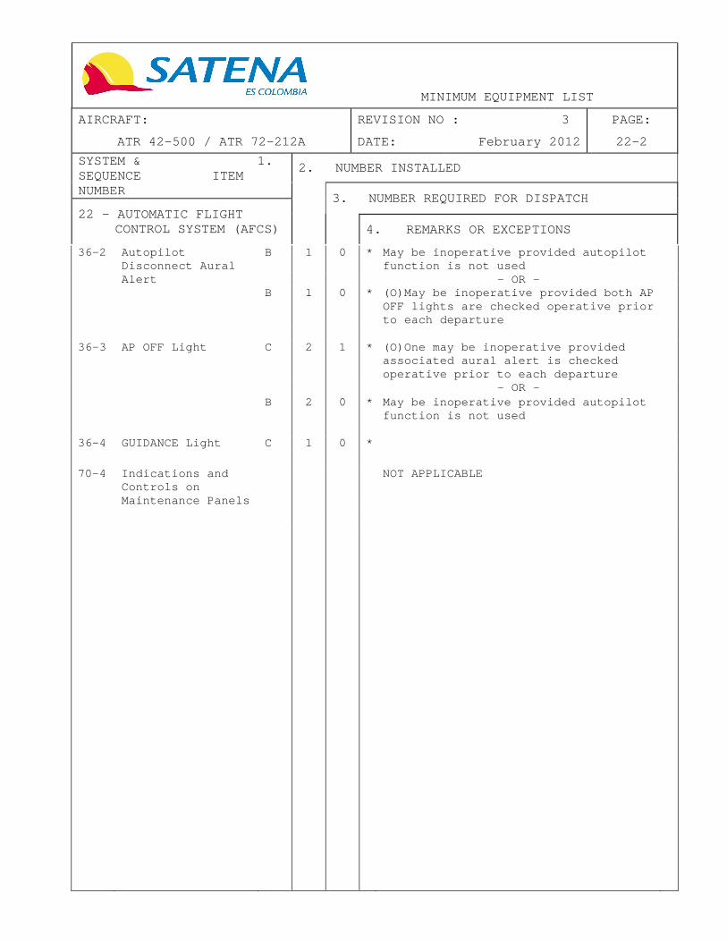
36-2 Autopilot Disconnect Aural
B 1 0 * May be inoperative provided autopilot function is not used
Alert - OR - B 1 0 * (O)May be inoperative provided both AP
OFF lights are checked operative prior to each departure
36-3 AP OFF Light C 2 1 * (O)One may be inoperative provided associated aural alert is checked operative prior to each departure
- OR - B 2 0 * May be inoperative provided autopilot
function is not used
36-4 GUIDANCE Light C 1 0 *
70-4 Indications and Controls on Maintenance Panels
NOT APPLICABLE

MINIMUM EQUIPMENT LIST
AIRCRAFT: REVISION NO : 4 PAGE:
ATR 42-500 / ATR 72-212A DATE: June 2012 23-1
SYSTEM & 1. SEQUENCE ITEM NUMBER
2. NUMBER INSTALLED
3. NUMBER REQUIRED FOR DISPATCH
23 - COMMUNICATIONS
4. REMARKS OR EXCEPTIONS
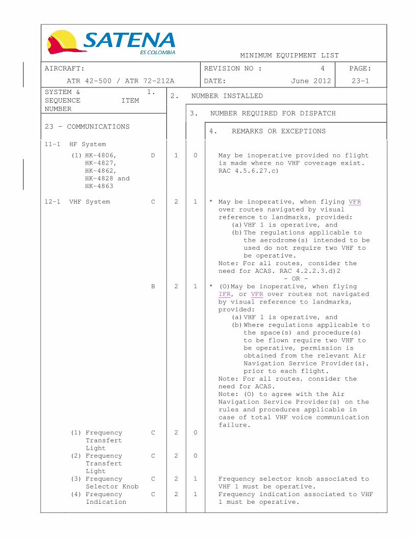
11-1 HF System
(1) HK-4806, HK-4827, HK-4862, HK-4828 and HK-4863
D 1 0 May be inoperative provided no flight is made where no VHF coverage exist. RAC 4.5.6.27.c)
12-1 VHF System C 2 1 * May be inoperative, when flying VFR over routes navigated by visual reference to landmarks, provided:
(a) VHF 1 is operative, and (b) The regulations applicable to
the aerodrome(s) intended to be used do not require two VHF to be operative.
Note: For all routes, consider the need for ACAS. RAC 4.2.2.3.d)2
- OR - B 2 1 * (O)May be inoperative, when flying
IFR , or VFR over routes not navigated by visual reference to landmarks, provided:
(a) VHF 1 is operative, and (b) Where regulations applicable to
the space(s) and procedure(s) to be flown require two VHF to be operative, permission is obtained from the relevant Air Navigation Service Provider(s), prior to each flight.
Note: For all routes, consider the need for ACAS. Note: (O) to agree with the Air Navigation Service Provider(s) on the rules and procedures applicable in case of total VHF voice communication failure.
(1) Frequency Transfert Light
C 2 0
(2) Frequency Transfert Light
C 2 0
(3) Frequency Selector Knob
C 2 1 Frequency selector knob associated to VHF 1 must be operative.
(4) Frequency Indication
C 2 1 Frequency indication associated to VHF 1 must be operative.


MINIMUM EQUIPMENT LIST
AIRCRAFT: REVISION NO : 4 PAGE:
ATR 42-500 / ATR 72-212A DATE: June 2012 23-2
SYSTEM & 1. SEQUENCE ITEM NUMBER
2. NUMBER INSTALLED
3. NUMBER REQUIRED FOR DISPATCH
23 - COMMUNICATIONS
4. REMARKS OR EXCEPTIONS
22-1 24-1
SELCAL (1) HK-4827, HK-4828 and HK-4863 ACARS (if installed)
D
1
0
*
NOT APPLICABLE
31-1 Passenger Address
System (1) Passenger
Configuration
A
1
0
*
(O)May be inoperative provided:
(a) Alternate normal, following failure and emergency procedures and/or operating restrictions are established and used, and
(b) Operations are limited to three calendar days or three flights whichever occurs first
44-1 Interphone System
(1) Ground Call Horn
C 1 0 (O)May be inoperative
(2) Flight Deck to Flight Deck
* Refer to MEL 23 page 3 items 50-1, 50-2, 50-3
(3) Flight Deck to Cabin / Cabin to Flight Deck
B 1 0 * (O)May be inoperative, provided: (a) Passenger Address operates
normally, and (b) Alternate normal, following
failure and emergency procedures are established and used.
(4) Cabin to Cabin C 1 0 * (O)May be inoperative, provided: (a) Passenger Address is operative,
and (b) Alternate normal, following
failure and emergency procedures are established and used
(5) Flight Crew to Ground / Ground to Flight Crew
C 1 0 * (O)May be inoperative, provided alternate normal, following failure and emergency procedures are established and used
(6) Alerting System
C 2 0 * Visual signal may be inoperative on the flight deck
- OR –
(Continued)


MINIMUM EQUIPMENT LIST
AIRCRAFT: REVISION NO : 4 PAGE:
ATR 42-500 / ATR 72-212A DATE: June 2012 23-3
SYSTEM & 1. SEQUENCE ITEM NUMBER
2. NUMBER INSTALLED
3. NUMBER REQUIRED FOR DISPATCH
23 - COMMUNICATIONS
4. REMARKS OR EXCEPTIONS
44-1 Interphone System (Cont'd) (6) Alerting
System
C
2
0
Both visual and aural signals may be inoperative in the cabin provided Passenger Address is operative from the flight deck
(7) Handsets C C
1
1
0
0
* *
Handsets at non-required stations may be inoperative
- OR - (O)One handset may be inoperative provided alternate procedures are established and us ed to compensate for the loss of PA and interphone function at the affected station
44-2 Cabin Chime
System: Flight Deck to Cabin, Seat Belt and Smoking Signs
C 1 0 (O)May be inoperative provided: (a) Passenger Address is operative,
and (b) Alternate normal, following
failure and emergency procedures are established and used
50-1 Audio Control
Panel C 3 2 * Provided CAPT and F/O panels are
operative except VOICE ONLY key which may be inoperative
50-2 Headset C 2 1 One may be inoperative, provide d for
each crew member on flight deck duty, associated boom set (headset function) is operative
50-3 Hand Microphone C 2 1 One may be inoperative, provided for
each crew member on flight deck duty, associated boom set is operative
50-4 Boom Set C 3 2 One may be inoperative, provided fo r
each crew member on flight deck duty, associated hand mike and headset are operative
50-5 Cockpit
Loudspeaker C 2 1 *


MINIMUM EQUIPMENT LIST
AIRCRAFT: REVISION NO : 3 PAGE:
ATR 42-500 / ATR 72-212A DATE: February 2012 23-4
SYSTEM & 1. SEQUENCE ITEM NUMBER
2. NUMBER INSTALLED
3. NUMBER REQUIRED FOR DISPATCH
23 - COMMUNICATIONS
4. REMARKS OR EXCEPTIONS
51-1 Push-To-Talk (PTT) Switch on Wheel
C 2 0 One or both may be inoperative, provided:
(a) INT/RAD switches on ACP are operative, and
(b) RAD PTT SW on Nose Wheel Steering Control Handwheel is operative, and
(c) There is no permanent/constant radio transmission
52-1 Radio Management
System For ATR MODELS “-600” version
NOT APPLICABLE
70-1 Cockpit Video Surveillance System (if installed)
C 1 0 * (O) May be inoperative provided: (a) Alternate procedures are
established and used, and (b) Interphone system is checked to
operate normally
71-1 Cockpit Voice
Recorder A 1 0 * One or more may be inoperative,
provided: (a) Operations are limited to eight
further consecutive flights or 72 hours whichever occurs first, with the cockpit voice recorder unserviceable, and
(b) Any flight data recorder required to be carried is operative. RAC PART IV APPENDIX A ITEM 4.1.5


MINIMUM EQUIPMENT LIST
AIRCRAFT: REVISION NO : 3 PAGE:
ATR 42-500 / ATR 72-212A DATE: February 2012 24-1
SYSTEM & 1. SEQUENCE ITEM NUMBER
2. NUMBER INSTALLED
3. NUMBER REQUIRED FOR DISPATCH
24 - ELECTRICAL POWER
4. REMARKS OR EXCEPTIONS
AC
21-1 Inverter A 2 1 * Inverter #2 only may be inoperative, provided:
(a) For day VMC flight only, and (b) AP use is prohibited below 1000
ft AGL, and (c) Operations are limited to not
more than two calendar days (d) TLU manual mode is operative
21-2 INV FAULT Alert C 2 0 * (O)May be inoperative provided
affected inverter is checked operative prior to each departure
21-3 AC Bus Tie Contactor
B 1 0 * May be inoperative provided DC generation Bus Tie Contactor is considered inoperative; refer to MEL 24 item 32-2
21-4 BUS OFF Alert C 2 0 *
ACW
22-1 ACW Generator Channel (Generator + Related GCU)
B 2 1 * (O)(M)One may be inoperative provided: (a) HYD AUX pump is operative, and (b) Two engines taxi is performed,
and (c) Aircraft is not operated on
narrow runways (width < 30 m (98 ft)), and
(d) Aircraft is not operated into known or forecast icing conditions, and
(e) AFM penalties are applied, and (f) Ground operations above 8500 ft
(when authorized), including taxi, do not exceed 10 minutes
22-2 ACW GEN FAULT
Alert C 2 1 * One may be inoperative provided ACW
BTC operates normally
22-3 ACW Generation Bus
Tie Contactor B 1 0 * (O)May be inoperative in the ISOL
position, provided: (a) Both ACW generator channels are
operative, and (b) HYD X FEED is operative and is
selected ON before take off, then OFF during cruise and reselected ON before landing
22-4 ACW BUS OFF Alert C 2 0 *


MINIMUM EQUIPMENT LIST
AIRCRAFT: REVISION NO : 3 PAGE:
ATR 42-500 / ATR 72-212A DATE: February 2012 24-2
SYSTEM & 1. SEQUENCE ITEM NUMBER
2. NUMBER INSTALLED
3. NUMBER REQUIRED FOR DISPATCH
24 - ELECTRICAL POWER
4. REMARKS OR EXCEPTIONS
DC 30-1 DC Generator
Channel (Generator + Related GCU) ATR42-300/320 ATR72-201/202/212
NOT APPLICABLE Refer to MEL 24 item 30-1 Page 2A
32-1 DC GEN FAULT Alert C 2 1 * Provided DC Bus Tie Contactor is
operative
32-2 DC Generation Bus Tie Contactor (BTC)
B 1 0 * (O)May be inoperative in the ISOL position, provided:
(a) Both DC generator channels are operative, and
(b) DC BUS OFF lights are operative, and
(c) Both inverters are operative, and
(d) HYD X FEED is operative and is selected ON before take off, then OFF during cruise and reselected ON before landing
32-3 SVCE & UTLY BUS
Control System C 1 0 * May be inoperative in the OFF position
32-4 DC BUS OFF Alert C 2 0 *
Miscellaneous
41-1 AC External Power Connection System
C 1 0 *
46-1 DC External Power Connection System
C 1 0 *
69-1 DC AMP Indicator (Left Hand Panel)
C 1 0
77-1 Indications and
Controls on Maintenance Panels
C 5 0

MINIMUM EQUIPMENT LIST
AIRCRAFT: REVISION NO : 3 PAGE:
ATR 42-500 / ATR 72-212A DATE: February 2012 24-2A
SYSTEM & 1. SEQUENCE ITEM NUMBER
2. NUMBER INSTALLED
3. NUMBER REQUIRED FOR DISPATCH
24 - ELECTRICAL POWER
4. REMARKS OR EXCEPTIONS
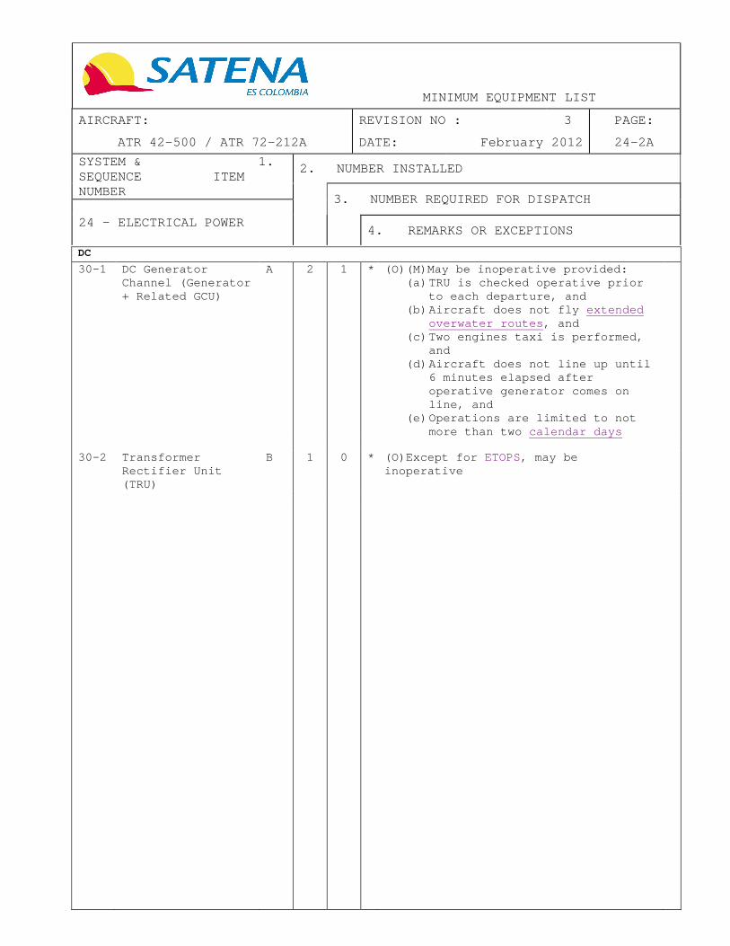
DC
30-1 DC Generator Channel (Generator + Related GCU)
A 2 1 * (O)(M)May be inoperative provided: (a) TRU is checked operative prior
to each departure, and (b) Aircraft does not fly extended
overwater routes , and (c) Two engines taxi is performed,
and (d) Aircraft does not line up until
6 minutes elapsed after operative generator comes on line, and
(e) Operations are limited to not more than two calendar days
30-2 Transformer
Rectifier Unit (TRU)
B 1 0 * (O)Except for ETOPS, may be inoperative


MINIMUM EQUIPMENT LIST
AIRCRAFT: REVISION NO : 4 PAGE:
ATR 42-500 / ATR 72-212A DATE: June 2012 25-1
SYSTEM & 1. SEQUENCE ITEM NUMBER
2. NUMBER INSTALLED
3. NUMBER REQUIRED FOR DISPATCH
25 - EQUIPMENT
4. REMARKS OR EXCEPTIONS
Note : A seat with an inoperative or missing seat belt o r harness is considered inoperative.
11-1 Flight Crew Seat B 2 2 * Vertical and recline adjustments may be inoperative provided associated seat is secured or locked in a position acceptable to the flig ht crew member Note: If an inoperative armrest will hinder an emergency evacuation or any other flight duties, it should be removed.
(1) Horizontal Adjustment
Must be operative for each flight crew member
11-2 Flight Deck Observer Seat
D 1 0 * May be inoperative provided the seat is correctly Stowed
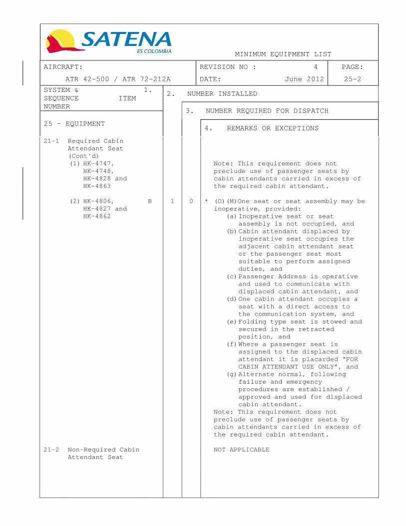
21-1 Required Cabin
Attendant Seat
(1) HK-4747, HK-4748, HK-4828 and HK-4863
B 2 0 * (O)(M)One seat or seat assembly may be inoperative, provided:
(a) Inoperative seat or seat assembly is not occupied, and
(b) Cabin attendant displaced by inoperative seat occupies the adjacent cabin attendant seat or the passenger seat most suitable to perform assigned duties, and
(c) Passenger Address is operative and used to communicate with displaced cabin attendant, and
(d) One cabin attendant occupies a seat with a direct access to the communication system, and
(e) Folding type seat is stowed and secured in the retracted position, and
(f) Where a passenger seat is assigned to the displaced cabin attendant it is placarded “FOR CABIN ATTENDANT USE ONLY”, and
(g) Alternate normal, following failure and emergency procedures are established / approved and used for displaced cabin attendant.
(Continued)

MINIMUM EQUIPMENT LIST
AIRCRAFT: REVISION NO : 4 PAGE:
ATR 42-500 / ATR 72-212A DATE: June 2012 25-2
SYSTEM & 1. SEQUENCE ITEM NUMBER
2. NUMBER INSTALLED
3. NUMBER REQUIRED FOR DISPATCH
25 - EQUIPMENT
4. REMARKS OR EXCEPTIONS
21-1 Required Cabin Attendant Seat (Cont'd)
(1) HK-4747, HK-4748, HK-4828 and HK-4863
Note: This requirement does not preclude use of passenger seats by cabin attendants carried in excess of the required cabin attendant.
(2) HK-4806, HK-4827 and HK-4862
B 1 0 * (O)(M)One seat or s eat assembly may be inoperative, provided:
(a) Inoperative seat or seat assembly is not occupied, and
(b) Cabin attendant displaced by inoperative seat occupies the adjacent cabin attendant seat or the passenger seat most suitable to perform assigned duties, and
(c) Passenger Address is operative and used to communicate with displaced cabin attendant, and
(d) One cabin attendant occupies a seat with a direct access to the communication system, and
(e) Folding type seat is stowed and secured in the retracted position, and
(f) Where a passenger seat is assigned to the displaced cabin attendant it is placarded “FOR CABIN ATTENDANT USE ONLY”, and
(g) Alternate normal, following failure and emergency procedures are established / approved and used for displaced cabin attendant.
Note: This requirement does not preclude use of passenger seats by cabin attendants carried in excess of the required cabin attendant.
21-2 Non-Required Cabin Attendant Seat
NOT APPLICABLE

MINIMUM EQUIPMENT LIST
AIRCRAFT: REVISION NO : 3 PAGE:
ATR 42-500 / ATR 72-212A DATE: February 2012 25-3
SYSTEM & 1. SEQUENCE ITEM NUMBER
2. NUMBER INSTALLED
3. NUMBER REQUIRED FOR DISPATCH
25 - EQUIPMENT
4. REMARKS OR EXCEPTIONS
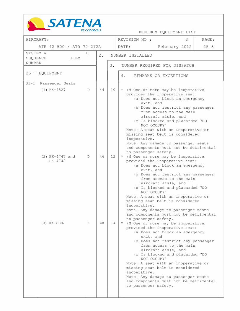
31-1 Passenger Seats
(1) HK-4827 D 44 10 * (M)One or more may be inoperative, provided the inoperative seat:
(a) Does not block an emergency exit, and
(b) Does not restrict any passenger from access to the main aircraft aisle, and
(c) Is blocked and placarded “DO NOT OCCUPY”
Note: A seat with an inoperative or missing seat belt is considered inoperative. Note: Any damage to passenger seats and components must not be detrimental to passenger safety.
(2) HK-4747 and HK-4748
D 46 12 * (M)One or more may be inoperative, provided the inoperative seat:
(a) Does not block an emergency exit, and
(b) Does not restrict any passenger from access to the main aircraft aisle, and
(c) Is blocked and placarded “DO NOT OCCUPY”
Note: A seat with an inoperative or missing seat belt is considered inoperative. Note: Any damage to passenger seats and components must not be detrimental to passenger safety.
(3) HK-4806 D 48 14 * (M)One or more may be inoperative, provided the inoperative seat:
(a) Does not block an emergency exit, and
(b) Does not restrict any passenger from access to the main aircraft aisle, and
(c) Is blocked and placarded “DO NOT OCCUPY”
Note: A seat with an inoperative or missing seat belt is considered inoperative. Note: Any damage to passenger seats and components must not be detrimental to passenger safety.

MINIMUM EQUIPMENT LIST
AIRCRAFT: REVISION NO : 4 PAGE:
ATR 42-500 / ATR 72-212A DATE: June 2012 25-4
SYSTEM & 1. SEQUENCE ITEM NUMBER
2. NUMBER INSTALLED
3. NUMBER REQUIRED FOR DISPATCH
25 - EQUIPMENT
4. REMARKS OR EXCEPTIONS
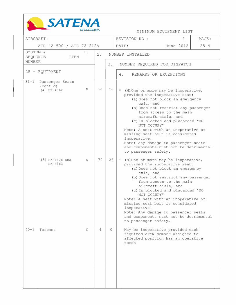
31-1 Passenger Seats (Cont'd) (4) HK-4862
D
50
16
*
(M)One or more may be inoperative, provided the inoperative seat:
(a) Does not block an emergency exit, and
(b) Does not restrict any passenger from access to the main aircraft aisle, and
(c) Is blocked and placarded “DO NOT OCCUPY”
Note: A seat with an inoperative or missing seat belt is considered inoperative. Note: Any damage to passenger seats and components must not be detrimental to passenger safety.
(5) HK-4828 and HK-4863
D 70 26 * (M)One or more may be inoperative, provided the inoperative seat:
(a) Does not block an emergency exit, and
(b) Does not restrict any passenger from access to the main aircraft aisle, and
(c) Is blocked and placarded “DO NOT OCCUPY”
Note: A seat with an inoperative or missing seat belt is considered inoperative. Note: Any damage to passenger seats and components must not be detrimental to passenger safety.
40-1 Torches C 4 0 May be inoperative provided eac h required crew member assigned to affected position has an operative torch


MINIMUM EQUIPMENT LIST
AIRCRAFT: REVISION NO : 4 PAGE:
ATR 42-500 / ATR 72-212A DATE: June 2012 25-5
SYSTEM & 1. SEQUENCE ITEM NUMBER
2. NUMBER INSTALLED
3. NUMBER REQUIRED FOR DISPATCH
25 - EQUIPMENT
4. REMARKS OR EXCEPTIONS
45-1 Portable Protective Breathing Equipment
(1) HK-4747, HK-4748, HK-4806 and HK-4862
D 2 2 * (M)Any in excess of that required may be inoperative or missing provided t he inoperative PBE is placarded inoperative, removed from the installed location, and placed out of sight so it cannot be mistaken for a functional unit
(2) HK-4862, HK-4828 and HK-4863
D 3 3 * (M)Any in excess of that required may be inoperative or missing provided t he inoperative PBE is placarded inoperative, removed from the installed location, and placed out of sight so it cannot be mistaken for a functional unit
50-1 Video System in Cabin Aircraft fitted with mod 5713
NOT APPLICABLE
60-1 ELT – Emergency locator Transmitter (1) Aircraft
Equipped With One ELT
1
1
Should be operative RAC 4.2.2.4
62-1 Megaphones (1) HK-4828 and
HK-4863 1 1
64-1 Crash Axes or
Crowbars 1 1
64-2 Lifejackets
(1) HK-4806, HK-4827 and HK-4862
C 4 0 When not flying more than 50NM en-route over water
(2) HK-4747, HK-4748, HK-4828 and HK-4863
C 5 0 When not flying more than 50NM en-route over water


MINIMUM EQUIPMENT LIST
AIRCRAFT: REVISION NO : 4 PAGE:
ATR 42-500 / ATR 72-212A DATE: June 2012 25-6
SYSTEM & 1. SEQUENCE ITEM NUMBER
2. NUMBER INSTALLED
3. NUMBER REQUIRED FOR DISPATCH
25 – EQUIPMENT
4. REMARKS OR EXCEPTIONS
70-1 SVCE PLUG Switch ATR 42-500 fitted with mod 5451+5452 or 5889+5870 ATR 72 fitted with mod 6063 +5928
NOT APPLICABLE
80-1 Separation Door
and Sliding Panels of the Partition ATR 42-500 fitted with mod 5451+5452 or 5889+5870 ATR 72 fitted with mod 6063 +5928
NOT APPLICABLE

MINIMUM EQUIPMENT LIST
AIRCRAFT: REVISION NO : 3 PAGE:
ATR 42-500 / ATR 72-212A DATE: February 2012 26-1
SYSTEM & 1. SEQUENCE ITEM NUMBER
2. NUMBER INSTALLED
3. NUMBER REQUIRED FOR DISPATCH
26 - FIRE PROTECTION
4. REMARKS OR EXCEPTIONS
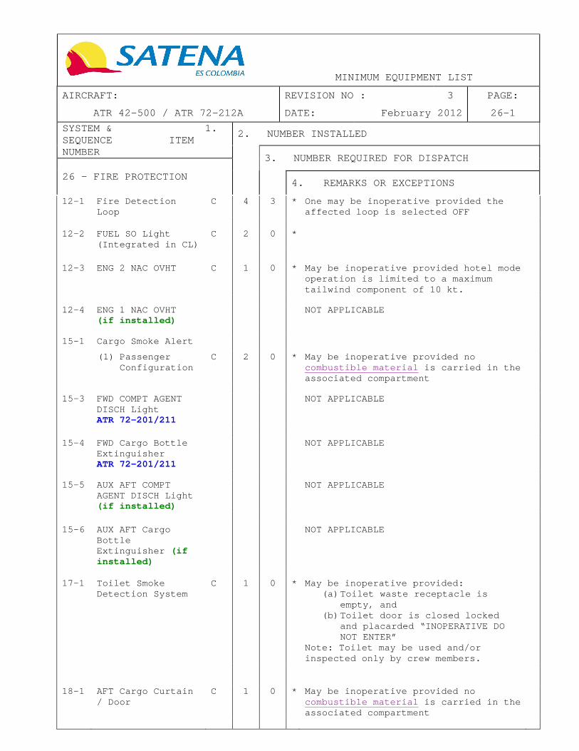
12-1 Fire Detection Loop
C 4 3 * One may be inoperative provided the affected loop is selected OFF
12-2 FUEL SO Light (Integrated in CL)
C 2 0 *
12-3 ENG 2 NAC OVHT C 1 0 * May be inoperative provided hotel mode operation is limited to a maximum tailwind component of 10 kt.
12-4 ENG 1 NAC OVHT
(if installed) NOT APPLICABLE
15-1 Cargo Smoke Alert
(1) Passenger Configuration
C 2 0 * May be inoperative provided no combustible material is carried in the associated compartment
15-3 FWD COMPT AGENT
DISCH Light ATR 72-201/211
NOT APPLICABLE
15-4 FWD Cargo Bottle Extinguisher ATR 72-201/211
NOT APPLICABLE
15-5 AUX AFT COMPT
AGENT DISCH Light (if installed)
NOT APPLICABLE
15-6 AUX AFT Cargo Bottle Extinguisher (if installed)
NOT APPLICABLE
17-1 Toilet Smoke Detection System
C 1 0 * May be inoperative provided: (a) Toilet waste receptacle is
empty, and (b) Toilet door is closed locked
and placarded “INOPERATIVE DO NOT ENTER”
Note: Toilet may be used and/or inspected only by crew members.
18-1 AFT Cargo Curtain / Door
C 1 0 * May be inoperative provided no combustible material is carried in the associated compartment

MINIMUM EQUIPMENT LIST
AIRCRAFT: REVISION NO : 4 PAGE:
ATR 42-500 / ATR 72-212A DATE: June 2012 26-2
SYSTEM & 1. SEQUENCE ITEM NUMBER
2. NUMBER INSTALLED
3. NUMBER REQUIRED FOR DISPATCH
26 - FIRE PROTECTION
4. REMARKS OR EXCEPTIONS
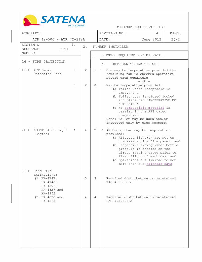
19-1 AFT Smoke Detection Fans
C 2 1 One may be inoperative provided the remaining fan is checked operative before each departure
- OR - C 2 0 May be inoperative provided:
(a) Toilet waste receptacle is empty, and
(b) Toilet door is closed locked and placarded “INOPERATIVE DO NOT ENTER”
(c) No combustible material is carried in the AFT cargo compartment
Note: Toilet may be used and/or inspected only by crew members.
21-1 AGENT DISCH Light (Engine)
A 4 2 * (M)One or two may be inoperative provided:
(a) Affected light(s) are not on the same engine fire panel, and
(b) Respective extinguisher bottle pressure is checked on the direct reading gauge prior to first flight of each day, and
(c) Operations are limited to not more than two calendar days
30-1 Hand Fire
Extinguisher
(1) HK-4747, HK-4748, HK-4806, HK-4827 and HK-4862
3 3 Required distribution is maintained RAC 4.5.6.6.c)
(2) HK-4828 and HK-4863
4 4 Required distribution is maintained RAC 4.5.6.6.c)

MINIMUM EQUIPMENT LIST
AIRCRAFT: REVISION NO : 3 PAGE:
ATR 42-500 / ATR 72-212A DATE: February 2012 27-1
SYSTEM & 1. SEQUENCE ITEM NUMBER
2. NUMBER INSTALLED
3. NUMBER REQUIRED FOR DISPATCH
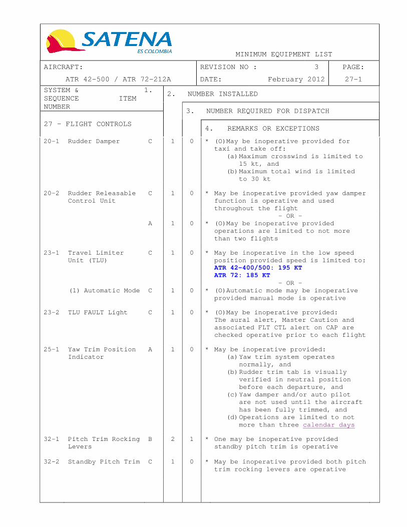
27 - FLIGHT CONTROLS
4. REMARKS OR EXCEPTIONS
20-1 Rudder Damper C 1 0 * (O)May be inoperative provided for taxi and take off:
(a) Maximum crosswind is limited to 15 kt, and
(b) Maximum total wind is limited to 30 kt
20-2 Rudder Releasable
Control Unit C 1 0 * May be inoperative provided yaw damper
function is operative and used throughout the flight
- OR - A 1 0 * (O)May be inoperative provided
operations are limited to not more than two flights
23-1 Travel Limiter
Unit (TLU) C 1 0 * May be inoperative in the low speed
position provided speed is limited to: ATR 42-400/500: 195 KT ATR 72: 185 KT
- OR - (1) Automatic Mode C 1 0 * (O)Automatic mode may be inoperative
provided manual mode is operative
23-2 TLU FAULT Light C 1 0 * (O)May be inoperative provided:
The aural alert, Master Caution and associated FLT CTL alert on CAP are checked operative prior to each flight
25-1 Yaw Trim Position
Indicator A 1 0 * May be inoperative provided:
(a) Yaw trim system operates normally, and
(b) Rudder trim tab is visually verified in neutral position before each departure, and
(c) Yaw damper and/or auto pilot are not used until the aircraft has been fully trimmed, and
(d) Operations are limited to not more than three calendar days
32-1 Pitch Trim Rocking
Levers B 2 1 * One may be inoperative provided
standby pitch trim is operative
32-2 Standby Pitch Trim C 1 0 * May be inoperative provided both pitch
trim rocking levers are operative

MINIMUM EQUIPMENT LIST
AIRCRAFT: REVISION NO : 3 PAGE:
ATR 42-500 / ATR 72-212A DATE: February 2012 27-2
SYSTEM & 1. SEQUENCE ITEM NUMBER
2. NUMBER INSTALLED
3. NUMBER REQUIRED FOR DISPATCH
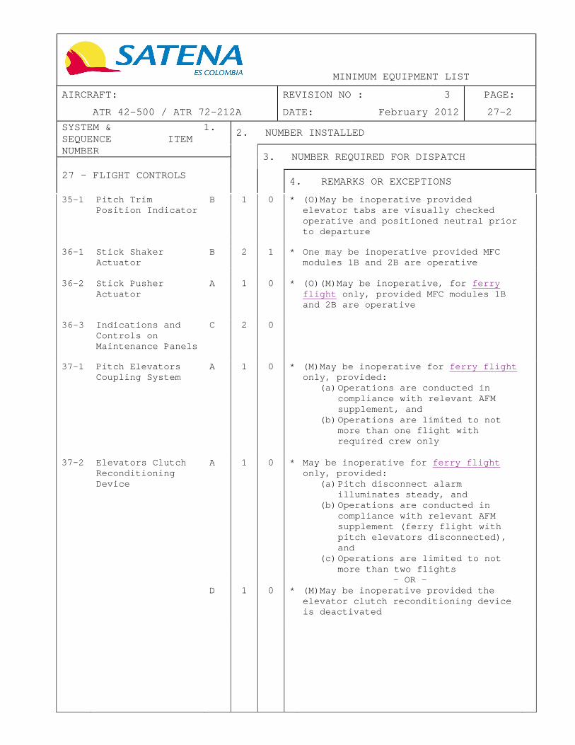
27 - FLIGHT CONTROLS
4. REMARKS OR EXCEPTIONS
35-1 Pitch Trim Position Indicator
B 1 0 * (O)May be inoperative provided elevator tabs are visually checked operative and positioned neutral prior to departure
36-1 Stick Shaker
Actuator B 2 1 * One may be inoperative provided MFC
modules 1B and 2B are operative
36-2 Stick Pusher Actuator
A 1 0 * (O)(M)May be inoperative, for ferry flight only, provided MFC modules 1B and 2B are operative
36-3 Indications and
Controls on Maintenance Panels
C 2 0
37-1 Pitch Elevators
Coupling System A 1 0 * (M)May be inoperative for ferry flight
only, provided: (a) Operations are conducted in
compliance with relevant AFM supplement, and
(b) Operations are limited to not more than one flight with required crew only
37-2 Elevators Clutch Reconditioning Device
A 1 0 * May be inoperative for ferry flight only, provided:
(a) Pitch disconnect alarm illuminates steady, and
(b) Operations are conducted in compliance with relevant AFM supplement (ferry flight with pitch elevators disconnected), and
(c) Operations are limited to not more than two flights
- OR - D 1 0 * (M)May be inoperative provided the
elevator clutch reconditioning device is deactivated

MINIMUM EQUIPMENT LIST
AIRCRAFT: REVISION NO : 3 PAGE:
ATR 42-500 / ATR 72-212A DATE: February 2012 27-3
SYSTEM & 1. SEQUENCE ITEM NUMBER
2. NUMBER INSTALLED
3. NUMBER REQUIRED FOR DISPATCH
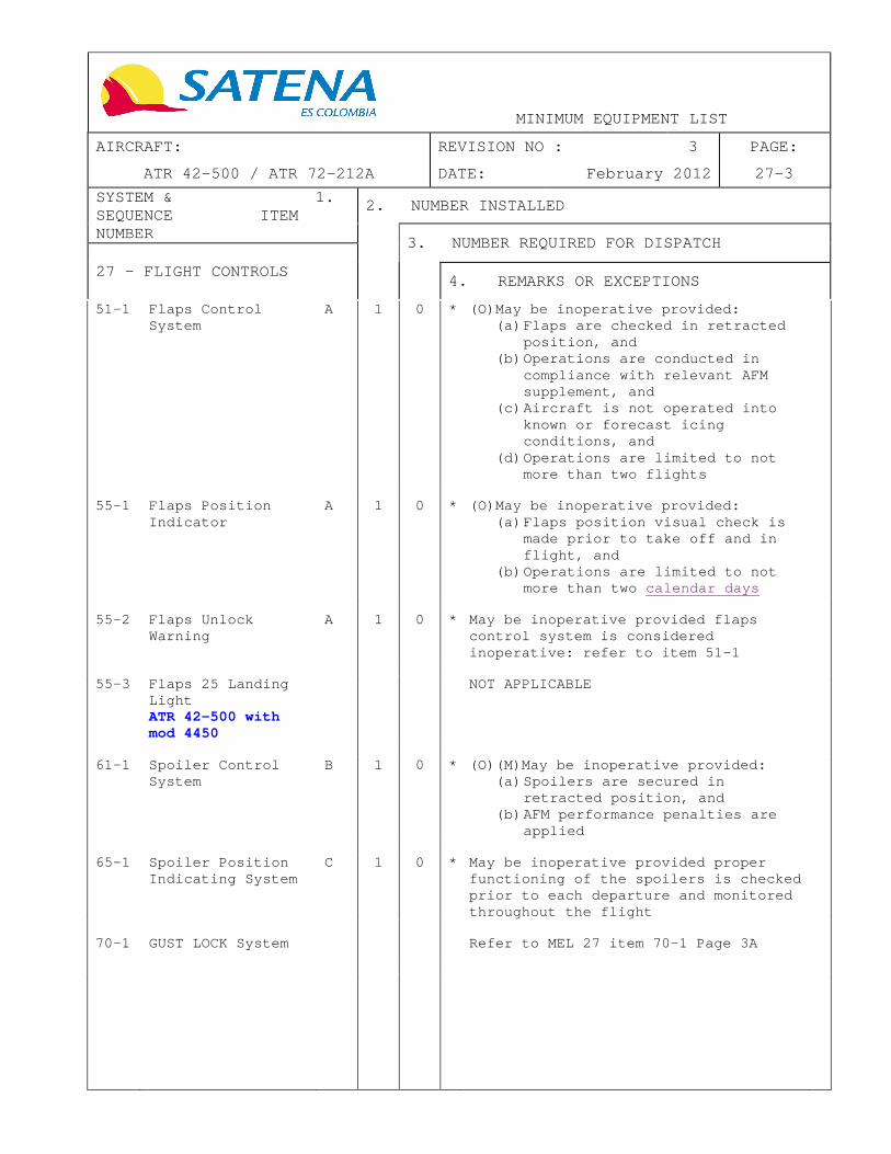
27 - FLIGHT CONTROLS
4. REMARKS OR EXCEPTIONS
51-1 Flaps Control System
A 1 0 * (O)May be inoperative provided: (a) Flaps are checked in retracted
position, and (b) Operations are conducted in
compliance with relevant AFM supplement, and
(c) Aircraft is not operated into known or forecast icing conditions, and
(d) Operations are limited to not more than two flights
55-1 Flaps Position
Indicator A 1 0 * (O)May be inoperative provided:
(a) Flaps position visual check is made prior to take off and in flight, and
(b) Operations are limited to not more than two calendar days
55-2 Flaps Unlock
Warning A 1 0 * May be inoperative provided flaps
control system is considered inoperative: refer to item 51-1
55-3 Flaps 25 Landing
Light ATR 42-500 with mod 4450
NOT APPLICABLE
61-1 Spoiler Control
System B 1 0 * (O)(M)May be inoperative provided:
(a) Spoilers are secured in retracted position, and
(b) AFM performance penalties are applied
65-1 Spoiler Position
Indicating System C 1 0 * May be inoperative provided proper
functioning of the spoilers is checked prior to each departure and monitored throughout the flight
70-1 GUST LOCK System Refer to MEL 27 item 70-1 Page 3A


MINIMUM EQUIPMENT LIST
AIRCRAFT: REVISION NO : 3 PAGE:
ATR 42-500 / ATR 72-212A DATE: February 2012 27-3A
SYSTEM & 1. SEQUENCE ITEM NUMBER
2. NUMBER INSTALLED
3. NUMBER REQUIRED FOR DISPATCH
27 - FLIGHT CONTROLS
4. REMARKS OR EXCEPTIONS
70-1 GUST LOCK System
(1) Aileron C 1 0 * (O)(M)May be inoperative provided the tailwind during parking does not exceed 40 kt Note: Propeller brake is not available
(2) Elevator C 1 0 * (O)(M)May be inoperative Note: Propeller brake is not available
70-2 AIL LOCK Light A 1 0 May be inoperative provided operations are limited to not more than two flights


MINIMUM EQUIPMENT LIST
AIRCRAFT: REVISION NO : 3 PAGE:
ATR 42-500 / ATR 72-212A DATE: February 2012 28-1
SYSTEM & 1. SEQUENCE ITEM NUMBER
2. NUMBER INSTALLED
3. NUMBER REQUIRED FOR DISPATCH
28 - FUEL SYSTEM
4. REMARKS OR EXCEPTIONS
21-1 FEED LO PR Light B 2 1 * (O)One may be inoperative provided: (a) Associated alert is processed
by the CCAS, and (b) Associated pump RUN light is
operative
21-2 Electrical Pump C 2 1 * (O)(M)One may be inoperative provided:
(a) Fuel X FEED valve is operative, and
(b) Associated jet pump (and motive flow valve) is operative
21-3 Pump RUN Light C 2 0 * May be inoperative provided associated
electrical pumps are operative
21-4 Jet Pump (and
Associated Motive Flow Valve)
C 2 1 * One may be inoperative provided: (a) Fuel X FEED valve is operative,
and (b) Associated electrical pump is
operative
21-5 Feeder Tank Jet
Pump C 2 1 One may be inoperative provided :
(a) Fuel X FEED valve is operative, and
(b) Both associated electrical pumps are operative, and
(c) Both fuel quantity indication systems are operative, and
(d) Fuel quantity unusable in each tank is raised from 20kg / 44Lb to 130Kg / 287Lb. Refueling must be done accordingly.
23-1 X FEED Valve C 1 0 * (O)May be inoperative except for
ETOPS, provided: (a) X FEED valve is checked in
closed position and, (b) Both fuel quantity indications
are operative
23-2 X FEED Flow Bar C 1 0 * (O)May be inoperative provided:
(a) X FEED valve is checked in close position, and
(b) Both fuel quantity indications are operative
23-3 Fuel X FEED Memo
light C 1 0 *


MINIMUM EQUIPMENT LIST
AIRCRAFT: REVISION NO : 3 PAGE:
ATR 42-500 / ATR 72-212A DATE: February 2012 28-2
SYSTEM & 1. SEQUENCE ITEM NUMBER
2. NUMBER INSTALLED
3. NUMBER REQUIRED FOR DISPATCH
28 - FUEL SYSTEM
4. REMARKS OR EXCEPTIONS
25-1 Refueling Control Panel
C 1 0 * May be inoperative Note: only refueling by gravity is available
(1) Fuel Preselector
C 1 0 * (M)May be inoperative
25-2 Pressure Refueling
Cap A 1 0 (M)May be inoperative provided:
(a) Refuel valves are confirmed closed, and
(b) There is no leakage from the refuel coupling, and
(c) Operations are limited to no more than three calendar days
26-1 LP Valve Position
Indicator C 2 0 *
41-1 Tank Temperature
Indication C 1 0 * May be inoperative
Note: OAT has to be used
42-1 Fuel QTY
Indication C 2 1 * (O)(M)One may be inoperative, except
for ETOPS, provided that: (a) The Associated FU indicator is
operative, and (b) The Opposite fuel LO LVL light
is operative, and (c) The Use of preselector is
prohibited during refueling, and
(d) The Fuel QTY in associated tank is checked after each refueling by fuel level sticks
Note: must be placarded inoperative the following:
- Cockpit fuel QTY indication - Pre-selector and fuel quantity
repeater indication on the refueling panel
42-2 Fuel LO LVL Light C 2 0 * May be inoperative, except for ETOPS,
provided associated alert is processed by CCAS
42-3 Fuel QTY Test
System C 1 0 *
43-1 Fuel Level Stick C 4 0 *

MINIMUM EQUIPMENT LIST
AIRCRAFT: REVISION NO : 3 PAGE:
ATR 42-500 / ATR 72-212A DATE: February 2012 29-1
SYSTEM & 1. SEQUENCE ITEM NUMBER
2. NUMBER INSTALLED
3. NUMBER REQUIRED FOR DISPATCH
29 - HYDRAULIC SYSTEM
4. REMARKS OR EXCEPTIONS
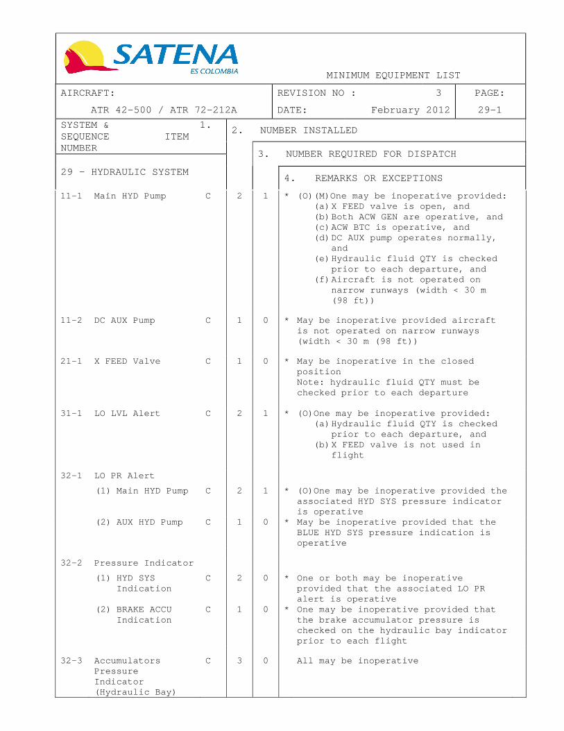
11-1 Main HYD Pump C 2 1 * (O)(M)One may be inoperative provided: (a) X FEED valve is open, and (b) Both ACW GEN are operative, and (c) ACW BTC is operative, and (d) DC AUX pump operates normally,
and (e) Hydraulic fluid QTY is checked
prior to each departure, and (f) Aircraft is not operated on
narrow runways (width < 30 m (98 ft))
11-2 DC AUX Pump C 1 0 * May be inoperative provided aircraft
is not operated on narrow runways (width < 30 m (98 ft))
21-1 X FEED Valve C 1 0 * May be inoperative in the closed
position Note: hydraulic fluid QTY must be checked prior to each departure
31-1 LO LVL Alert C 2 1 * (O)One may be inoperative provided: (a) Hydraulic fluid QTY is checked
prior to each departure, and (b) X FEED valve is not used in
flight
32-1 LO PR Alert
(1) Main HYD Pump C 2 1 * (O)One may be inoperative provided the associated HYD SYS pressure indicator is operative
(2) AUX HYD Pump C 1 0 * May be inoperative provided that the BLUE HYD SYS pressure indication is operative
32-2 Pressure Indicator
(1) HYD SYS Indication
C 2 0 * One or both may be inoperative provided that the associated LO PR alert is operative
(2) BRAKE ACCU Indication
C 1 0 * One may be inoperative provided that the brake accumulator pressure is checked on the hydraulic bay indicator prior to each flight
32-3 Accumulators
Pressure Indicator (Hydraulic Bay)
C 3 0 All may be inoperative


MINIMUM EQUIPMENT LIST
AIRCRAFT: REVISION NO : 3 PAGE:
ATR 42-500 / ATR 72-212A DATE: February 2012 29-2
SYSTEM & 1. SEQUENCE ITEM NUMBER
2. NUMBER INSTALLED
3. NUMBER REQUIRED FOR DISPATCH
29 - HYDRAULIC SYSTEM
4. REMARKS OR EXCEPTIONS
33-1 Main Hydraulic Pump OVHT Alert
C 2 1 * (O)One may be inoperative provided: (a) The associated pump is
considered inoperative, and (b) The other main hydraulic pump
and associated OVHT alert is operative; refer to MEL 29 item 11-1
33-2 DC AUX Pump OVHT Alert
C 1 0 * (O) May be inoperative provided that the pump is considered inoperative; refer to MEL 29 item 11-2

MINIMUM EQUIPMENT LIST
AIRCRAFT: REVISION NO : 3 PAGE:
ATR 42-500 / ATR 72-212A DATE: February 2012 30-1
SYSTEM & 1. SEQUENCE ITEM NUMBER
2. NUMBER INSTALLED
3. NUMBER REQUIRED FOR DISPATCH
30 - ICE AND RAIN PROTECTION
4. REMARKS OR EXCEPTIONS
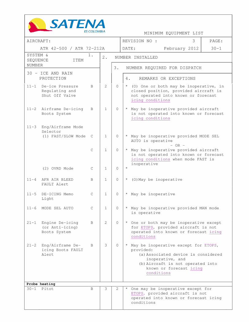
11-1 De-ice Pressure Regulating and Shut Off Valve
B 2 0 * (O) One or both may be inoperative, in closed position, provided aircraft is not operated into known or forecast icing conditions
11-2 Airframe De-icing
Boots System B 1 0 * May be inoperative provided aircraft
is not operated into known or forecast icing conditions
11-3 Eng/Airframe Mode
Selector
(1) FAST/SLOW Mode C 1 0 * May be inoperative provided MODE SEL AUTO is operative
- OR - C 1 0 * May be inoperative provided aircraft
is not operated into known or forecast icing conditions when mode FAST is inoperative
(2) OVRD Mode C 1 0 *
11-4 AFR AIR BLEED FAULT Alert
B 1 0 * (O)May be inoperative
11-5 DE-ICING Memo Light
C 1 0 * May be inoperative
11-6 MODE SEL AUTO C 1 0 * May be inoperative provided MAN mode is operative
21-1 Engine De-icing (or Anti-icing) Boots System
B 2 0 * One or both may be inoperative except for ETOPS, provided aircraft is not operated into known or forecast icing conditions
21-2 Eng/Airframe De-
icing Boots FAULT Alert
B 3 0 * May be inoperative except for ETOPS, provided:
(a) Associated device is considered inoperative, and
(b) Aircraft is not operated into known or forecast icing conditions
Probe heating
30-1 Pitot B 3 2 * One may be inoperative except for ETOPS, provided aircraft is not operated into known or forecast icing conditions


MINIMUM EQUIPMENT LIST
AIRCRAFT: REVISION NO : 3 PAGE:
ATR 42-500 / ATR 72-212A DATE: February 2012 30-2
SYSTEM & 1. SEQUENCE ITEM NUMBER
2. NUMBER INSTALLED
3. NUMBER REQUIRED FOR DISPATCH
30 - ICE AND RAIN PROTECTION
4. REMARKS OR EXCEPTIONS
30-2 Static B 6 5 * One may be inoperative provided both STBY are operative
31-1 TAT B 2 1 * (O)
31-2 Alpha B 2 1 * One may be inoperative provided
aircraft is not operated into known or forecast icing conditions
31-3 Alert B 10 6 * (O)Provided:
(a) Two pitot alerts are operative, and
(b) Two static alerts are operative, and
(c) One TAT alert is operative, and (d) One alpha alert is operative,
and (e) Heating system associated to
failed alerts are checked operative prior to each departure
Horn anti - icing
53-1 Horn Anti-icing System
A 2 1 * May be inoperative provided: (a) Aircraft is not operated into
known or forecast icing conditions , and
(b) Operations are limited to not more than three calendar days
53-2 Horn Anti-icing
FAULT Alert A 2 1 * Associated devices must be considered
inoperative: refer to MEL 30 item 53-1
Window heating 60-1 Windshield C 2 1 * One may be inoperative provided
aircraft is not operated into known or forecast icing conditions
- OR - C 2 1 * One may be inoperative provided both
side windows heating are operative
- OR - C 2 0 * May be inoperative provided:
(a) Both packs are operative, and (b) Aircraft is not operated into
known or forecast icing conditions


MINIMUM EQUIPMENT LIST
AIRCRAFT: REVISION NO : 3 PAGE:
ATR 42-500 / ATR 72-212A DATE: February 2012 30-3
SYSTEM & 1. SEQUENCE ITEM NUMBER
2. NUMBER INSTALLED
3. NUMBER REQUIRED FOR DISPATCH
30 - ICE AND RAIN PROTECTION
4. REMARKS OR EXCEPTIONS
60-2 Side Window C 2 0 * May be inoperative provided aircraft is not operated into known or forecast icing conditions when LH side window heating is inoperative
- OR - C 2 0 * May be inoperative provided:
(a) Both windshields heating are operative, and
(b) Both ACW GEN are operative
60-3 Side Windows FAULT
Light C 1 0 * May be inoperative provided aircraft
is not operated into known or forecast icing conditions
60-4 WINDSHIELD HTG
FAULT Light C 2 1 * (O)One may be inoperative provided
respective heating system is checked operative prior to each departure
- OR - C 2 1 * One may be inoperative provided:
(a) Aircraft is not operated into known or forecast icing conditions , and
(b) Respective heating system is not used
Propeller anti - icing
61-1 Propeller Anti-icing System
C 2 0 * May be inoperative except for ETOPS, provided aircraft is not operated into known or forecast icing conditions
61-2 Propeller Anti-
icing ON Light C 2 0 * (O)May be inoperative provided FAULT
alert is operative
61-3 Propeller Mode
Selector C 1 0 * May be inoperative provided aircraft
is not operated into known or forecast icing conditions
61-4 Propeller FAULT
Alert C 2 0 * May be inoperative provided aircraft
is not operated into known or forecast icing conditions
61-5 Mode SEL AUTO C 1 0 * May be inoperative provided MAN MODE
is operative

MINIMUM EQUIPMENT LIST
AIRCRAFT: REVISION NO : 3 PAGE:
ATR 42-500 / ATR 72-212A DATE: February 2012 30-4
SYSTEM & 1. SEQUENCE ITEM NUMBER
2. NUMBER INSTALLED
3. NUMBER REQUIRED FOR DISPATCH
30 - ICE AND RAIN PROTECTION
4. REMARKS OR EXCEPTIONS
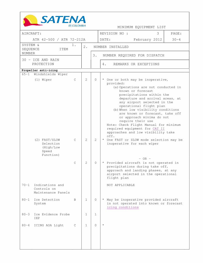
Propeller anti - icing
65-1 Windshields Wiper
(1) Wiper C 2 0 * One or both may be inoperative, provided:
(a) Operations are not conducted in known or forecast precipitations within the departure and arrival areas, at any airport selected in the operational flight plan
(b) When low visibility conditions are known or forecast, take off or approach minima do not require their use
Note: Check Flight Manual for minimum required equipment for CAT II approaches and low visibility take off.
(2) FAST/SLOW Selection (High/Low Speed Function)
C 2 2 * One FAST or SLOW mode selection may be inoperative for each wiper
- OR - C 2 0 * Provided aircraft is not operated in
precipitations during take off, approach and landing phases, at any airport selected in the operational flight plan
70-1 Indications and
Controls on Maintenance Panels
NOT APPLICABLE
80-1 Ice Detection
System B 1 0 * May be inoperative provided aircraft
is not operated into known or forecast icing conditions
80-3 Ice Evidence Probe
IEP 1 1
80-4 ICING AOA Light C 1 0 *


MINIMUM EQUIPMENT LIST
AIRCRAFT: REVISION NO : 4 PAGE:
ATR 42-500 / ATR 72-212A DATE: June 2012 31-1
SYSTEM & 1. SEQUENCE ITEM NUMBER
2. NUMBER INSTALLED
3. NUMBER REQUIRED FOR DISPATCH
31 - INSTRUMENTS
4. REMARKS OR EXCEPTIONS
21-1 Clock C 2 0 * One or both may be inoperative provided an accurate timepiece is operative on the flight deck indicating the time in hours, minutes and seconds Note: On the basis that the timepiece(s) required does not need to be approved, an accurate pilot’s wristwatch that indicates hours, minutes and seconds would be acceptable
31-1 MPC (HK-4747,
HK-4748, HK-4828 and HK-4863)
(1) APM FAULT Only C 1 0 * (O)May be inoperative
(2) DMU : Flight Recording Functions (Date, time and flight number)
* Refer to MEL 31 item 32-1 Note: No parameter acquisition
(3) DMU : Maintenance Function
C 1 0 * May be inoperative
(4) AFDAU * Refer to MEL 31 item 32-1 Note: No parameter acquisition
31-2 FDAU * Refer to MEL 31 item 32-1 and to MEL
77 item 13-1 Note: No parameter acquisition


MINIMUM EQUIPMENT LIST
AIRCRAFT: REVISION NO : 5 PAGE:
ATR 42-500 / ATR 72-212A DATE: December 2012 31-2
SYSTEM & 1. SEQUENCE ITEM NUMBER
2. NUMBER INSTALLED
3. NUMBER REQUIRED FOR DISPATCH
31 - INSTRUMENTS
4. REMARKS OR EXCEPTIONS
32-1 Digital Flight Data Recorder – DFDR
A 1 0 * May be inoperative provided repairs are made within 3 flight days Item R.A.C. part IV, Appendix A, Chapter 2, Numeral 4.1.5
32-2 AIDS (if
installed) NOT APPLICABLE
32-3 QAR (if installed) NOT APPLICABLE
48-1 Multi Function
Computer (MFC) module
* Refer to MEL 31 pages 4 and 5 for this item
48-6 MFC module FAULT
light A 4 3 * One may be inoperative provided
associated module is considered inoperative: Refer to item 48-1
CCAS
53-1 Crew Alerting Computer (CAC) ATR 42-300/320
NOT APPLICABLE
53-2 Master Warning
(MW) Light and Associated Cancel Function
C 2 1 * One may be inoperative provided: (a) The aural warnings are
operative, and (b) All warning lights on the CAP
panel are operative
53-3 Master Caution
(MC) Light and Associated Cancel Function
C 2 1 * One may be inoperative provided: (a) The aural caution is operative,
and (b) All caution lights on the CAP
panel are operative

MINIMUM EQUIPMENT LIST
AIRCRAFT: REVISION NO : 3 PAGE:
ATR 42-500 / ATR 72-212A DATE: February 2012 31-3
SYSTEM & 1. SEQUENCE ITEM NUMBER
2. NUMBER INSTALLED
3. NUMBER REQUIRED FOR DISPATCH
31 - INSTRUMENTS
4. REMARKS OR EXCEPTIONS
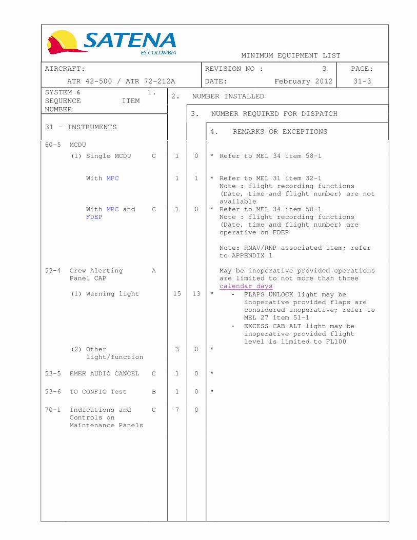
60-5 MCDU
(1) Single MCDU C 1 0 * Refer to MEL 34 item 58-1
With MPC 1 1 * Refer to MEL 31 item 32-1 Note : flight recording functions (Date, time and flight number) are not available
With MPC and FDEP
C 1 0 * Refer to MEL 34 item 58-1 Note : flight recording functions (Date, time and flight number) are operative on FDEP Note: RNAV/RNP associated item; refer to APPENDIX 1
53-4 Crew Alerting
Panel CAP A May be inop erative provided operations
are limited to not more than three calendar days
(1) Warning light 15 13 * - FLAPS UNLOCK light may be inoperative provided flaps are considered inoperative; refer to MEL 27 item 51-1
- EXCESS CAB ALT light may be inoperative provided flight level is limited to FL100
(2) Other light/function
3 0 *
53-5 EMER AUDIO CANCEL C 1 0 *
53-6 TO CONFIG Test B 1 0 *
70-1 Indications and
Controls on Maintenance Panels
C 7 0

MINIMUM EQUIPMENT LIST
AIRCRAFT: REVISION NO : 3 PAGE:
ATR 42-500 / ATR 72-212A DATE: February 2012 31-4
SYSTEM & 1. SEQUENCE ITEM NUMBER
2. NUMBER INSTALLED
3. NUMBER REQUIRED FOR DISPATCH
31 - INSTRUMENTS
4. REMARKS OR EXCEPTIONS
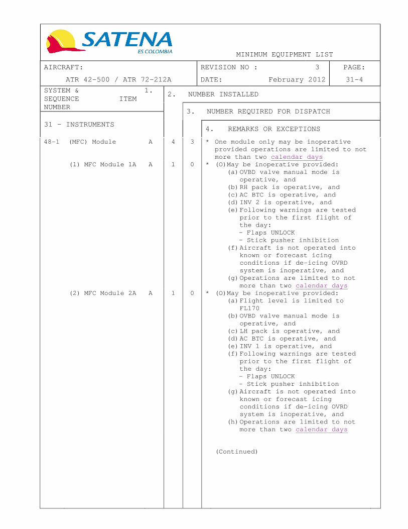
48-1 (MFC) Module A 4 3 * One module only may be inoperative provided operations are limited to not more than two calendar days
(1) MFC Module 1A A 1 0 * (O)May be inoperative provided: (a) OVBD valve manual mode is
operative, and (b) RH pack is operative, and (c) AC BTC is operative, and (d) INV 2 is operative, and (e) Following warnings are tested
prior to the first flight of the day: - Flaps UNLOCK - Stick pusher inhibition
(f) Aircraft is not operated into known or forecast icing conditions if de-icing OVRD system is inoperative, and
(g) Operations are limited to not more than two calendar days
(2) MFC Module 2A A 1 0 * (O)May be inoperative provided: (a) Flight level is limited to
FL170 (b) OVBD valve manual mode is
operative, and (c) LH pack is operative, and (d) AC BTC is operative, and (e) INV 1 is operative, and (f) Following warnings are tested
prior to the first flight of the day: - Flaps UNLOCK - Stick pusher inhibition
(g) Aircraft is not operated into known or forecast icing conditions if de-icing OVRD system is inoperative, and
(h) Operations are limited to not more than two calendar days
(Continued)

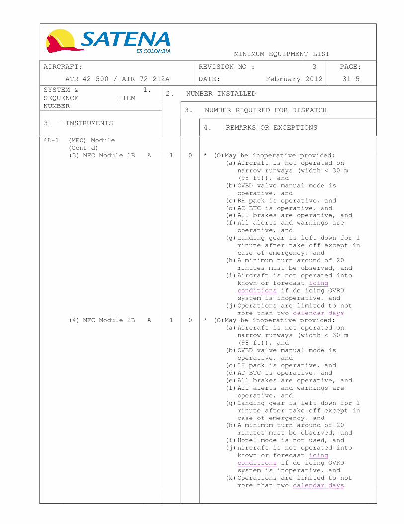
MINIMUM EQUIPMENT LIST
AIRCRAFT: REVISION NO : 3 PAGE:
ATR 42-500 / ATR 72-212A DATE: February 2012 31-5
SYSTEM & 1. SEQUENCE ITEM NUMBER
2. NUMBER INSTALLED
3. NUMBER REQUIRED FOR DISPATCH
31 - INSTRUMENTS
4. REMARKS OR EXCEPTIONS
48-1 (MFC) Module (Cont'd)
(3) MFC Module 1B A 1 0 * (O)May be inoperative provided: (a) Aircraft is not operated on
narrow runways (width < 30 m (98 ft)), and
(b) OVBD valve manual mode is operative, and
(c) RH pack is operative, and (d) AC BTC is operative, and (e) All brakes are operative, and (f) All alerts and warnings are
operative, and (g) Landing gear is left down for 1
minute after take off except in case of emergency, and
(h) A minimum turn around of 20 minutes must be observed, and
(i) Aircraft is not operated into known or forecast icing conditions if de icing OVRD system is inoperative, and
(j) Operations are limited to not more than two calendar days
(4) MFC Module 2B A 1 0 * (O)May be inoperative provided: (a) Aircraft is not operated on
narrow runways (width < 30 m (98 ft)), and
(b) OVBD valve manual mode is operative, and
(c) LH pack is operative, and (d) AC BTC is operative, and (e) All brakes are operative, and (f) All alerts and warnings are
operative, and (g) Landing gear is left down for 1
minute after take off except in case of emergency, and
(h) A minimum turn around of 20 minutes must be observed, and
(i) Hotel mode is not used, and (j) Aircraft is not operated into
known or forecast icing conditions if de icing OVRD system is inoperative, and
(k) Operations are limited to not more than two calendar days


MINIMUM EQUIPMENT LIST
AIRCRAFT: REVISION NO : 3 PAGE:
ATR 42-500 / ATR 72-212A DATE: February 2012 32-1
SYSTEM & 1. SEQUENCE ITEM NUMBER
2. NUMBER INSTALLED
3. NUMBER REQUIRED FOR DISPATCH
32 - LANDING GEAR
4. REMARKS OR EXCEPTIONS
31-1 Anti Retraction System (Lever Latch)
C 1 0 * May be inoperative
31-2 Landing Gear Lever
Integrated Red Light
C 1 0 * May be inoperative
31-3 Landing Gear Lever Retraction System and Uplocking System
A 1 0 * (O)May be inoperative provided: (a) The flight is performed with
landing gear down in compliance with AFM, and
(b) Aircraft is not operated into known or forecast icing conditions , and
(c) Operations are limited to not more than two calendar days
42-1 Wheel Brake C 4 3 * (O)(M)One may be inoperative provided:
(a) Anti-skid system is operative, and
(b) Affected brake is deactivated, and
(c) AFM performance penalty is applied
42-2 Anti-skid System C 1 0 * (O)May be inoperative provided
operations are conducted in compliance with AFM
42-3 BRK TEMP Alert C 1 0 * May be inoperative provided:
(a) Landing gear is left down for 1 minute after take off except in case of emergency, and
(b) A minimum turn around of 20 minutes is observed
45-1 PRKG BRK Light (on
CAP) C 1 0 * May be inoperative provided the
parking brake is operative
51-1 Nose Wheel
Steering C 1 0 * (O)May be inoperative provided:
(a) Centering function is not affected, and
(b) All brakes are operative, and (c) Maximum crosswind component is
limited to 15 kt, and (d) Aircraft is not operated on
narrow runways (width < 30 m (98 ft))


MINIMUM EQUIPMENT LIST
AIRCRAFT: REVISION NO : 3 PAGE:
ATR 42-500 / ATR 72-212A DATE: February 2012 32-2
SYSTEM & 1. SEQUENCE ITEM NUMBER
2. NUMBER INSTALLED
3. NUMBER REQUIRED FOR DISPATCH
32 - LANDING GEAR
4. REMARKS OR EXCEPTIONS
61-1 Landing Gear Position Indicating System
B 2 1 * (O)May be inoperative
61-2 LDG GEAR NOT DN
Warning System ATR 42-300/320
NOT APPLICABLE

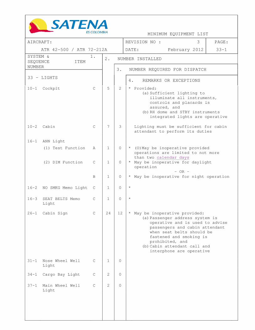
MINIMUM EQUIPMENT LIST
AIRCRAFT: REVISION NO : 3 PAGE:
ATR 42-500 / ATR 72-212A DATE: February 2012 33-1
SYSTEM & 1. SEQUENCE ITEM NUMBER
2. NUMBER INSTALLED
3. NUMBER REQUIRED FOR DISPATCH
33 - LIGHTS
4. REMARKS OR EXCEPTIONS
10-1 Cockpit C 5 2 * Provided: (a) Sufficient lighting to
illuminate all instruments, controls and placards is assured, and
(b) RH dome and STBY instruments integrated lights are operative
10-2 Cabin C 7 3 Lighting must be sufficient for c abin attendant to perform its duties
16-1 ANN Light
(1) Test Function A 1 0 * (O)May be inoperative provided operations are limited to not more than two calendar days
(2) DIM Function C 1 0 * May be inoperative for daylight operation
- OR - B 1 0 * May be inoperative for night operation
16-2 NO SMKG Memo Light C 1 0 *
16-3 SEAT BELTS Memo
Light C 1 0 *
26-1 Cabin Sign C 24 12 * May be inoperative provided: (a) Passenger address system is
operative and is used to advise passengers and cabin attendant when seat belts should be fastened and smoking is prohibited, and
(b) Cabin attendant call and interphone are operative
31-1 Nose Wheel Well Light
C 1 0
34-1 Cargo Bay Light C 2 0
37-1 Main Wheel Well
Light C 2 0

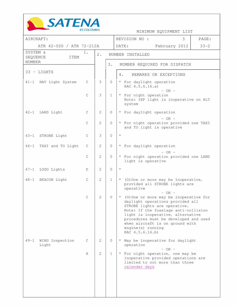
MINIMUM EQUIPMENT LIST
AIRCRAFT: REVISION NO : 3 PAGE:
ATR 42-500 / ATR 72-212A DATE: February 2012 33-2
SYSTEM & 1. SEQUENCE ITEM NUMBER
2. NUMBER INSTALLED
3. NUMBER REQUIRED FOR DISPATCH
33 - LIGHTS
4. REMARKS OR EXCEPTIONS
41-1 NAV Light System C 3 0 * For daylight operation RAC 4.5.6.16.a)
- OR - C 3 1 * For night operation
Note: IEP light is inoperative on ALT system
42-1 LAND Light C 2 0 * For daylight operation
- OR - C 2 0 * For night operation provided one TAXI
and TO light is operative
43-1 STROBE Light C 3 0 *
46-1 TAXI and TO Light C 2 0 * For daylight operation
- OR - C 2 0 * For night operation provided one LAND
light is operative
47-1 LOGO Lights D 2 0 *
48-1 BEACON Light C 2 1 * (O)One or more may be inoperative,
provided all STROBE lights are operative
- OR - C 2 0 * (O)One or more may be inoperative for
daylight operations provided all STROBE lights are operative. Note: If the fuselage anti-collision light is inoperative, alternative procedures must be developed and used when aircraft is on ground with engine(s) running RAC 4.5.6.16.b)
49-1 WING Inspection
Light C 2 0 * May be inoperative for daylight
operation
- OR - A 2 1 * For night operation, one may be
inoperative provided operations are limited to not more than three calendar days


MINIMUM EQUIPMENT LIST
AIRCRAFT: REVISION NO : 4 PAGE:
ATR 42-500 / ATR 72-212A DATE: June 2012 33-3
SYSTEM & 1. SEQUENCE ITEM NUMBER
2. NUMBER INSTALLED
3. NUMBER REQUIRED FOR DISPATCH
33 - LIGHTS
4. REMARKS OR EXCEPTIONS
49-2 IEP Light C 1 0 May be inoperative for daylig ht operation
- OR - A 1 0 (O)For night operation may be
inoperative provided: (a) Aircraft is not operated into
known or forecast icing conditions , and
(b) Operations are limited to not more than three calendar days
50-1 EMER EXIT "DISARM"
Light C 1 0 * Provided EMER EXIT light system is
operative and armed prior to each departure
50-2 Floor Proximity
Emergency Escape Path Marking Lights HK-4747, HK-4748, HK-4806, HK-4827 and HK-4862
B 6 4 Provided: (a) Two consecutive bulbs are not
inoperative, and (b) The two extreme bulbs are
operative
Photoluminescent
floor proximity emergency escape path marking lights HK-4828 and HK-4863
C 1 1 Provided: (a) No more than one meter of
photoluminescent tape is inoperative on each strip, and
(b) This inoperative part is neither facing nor continuous to an emergency exit
50-3 Ceiling Emergency
Lightning B 4 1 Provided a maximum of one in four
consecutive overhead emergency lights may be inoperative
50-4 Emergency Exit
Signs C 10 5 * Up to 50% of the bulbs may be
inoperative in one or more signs
- OR - A 10 5 * One may be inoperative provided
associated exit is considered inoperative: refer to MEL 52
51-1 Exterior EMER
Lights B 5 0 One light may be inoperative for
daylight operation only. For night operation refer to MEL 52 items 21-1


MINIMUM EQUIPMENT LIST
AIRCRAFT: REVISION NO : 3 PAGE:
ATR 42-500 / ATR 72-212A DATE: February 2012 34-1
SYSTEM & 1. SEQUENCE ITEM NUMBER
2. NUMBER INSTALLED
3. NUMBER REQUIRED FOR DISPATCH
34 - NAVIGATION
4. REMARKS OR EXCEPTIONS
Air Data System
11-1 Air data Computer (ADC)
A 2 1 * (O)ADC 2 only may be inoperative, provided:
(a) The autopilot use is prohibited below 1000 ft AGL, and
(b) For day VMC flight only, and (c) Operations are limited to not
more than two calendar days , and
(d) TLU manual mode is operative
12-2 STBY Altimeter C 1 1 * Vibrator may be inoperative
12-3 Main Altimeter A 2 1 * For day VMC flight only, one may
inoperative provided: (a) Standby altimeter is fully
operative, and (b) Operations are limited to not
more than two calendar days
13-1 Airspeed Indicator
(1) Speed Indication
A 3 2 * One may be inoperative provided: (a) Standby airspeed indicator is
operative, and (b) Operations are limited to not
more than two calendar days
(2) Speed Selector C 2 0 * (O)
14-1 Vertical Speed
Indicator C 2 1 * One may be inoperative
15-1 TAT/SAT - TAS Indicator
(1) TAS Indication C 1 0 * May be inoperative
(2) Temperature Indication
C 2 0 * (O) Both may be inoperative
(3) SAT Switching C 1 0 * May be inoperative
21-2 ADC Switch B 1 0 * May be inoperative provided associated
ADC is operative
21-3 ADC Switch FAULT
Light C 1 0 * May be inoperative provided both ADC
are operative

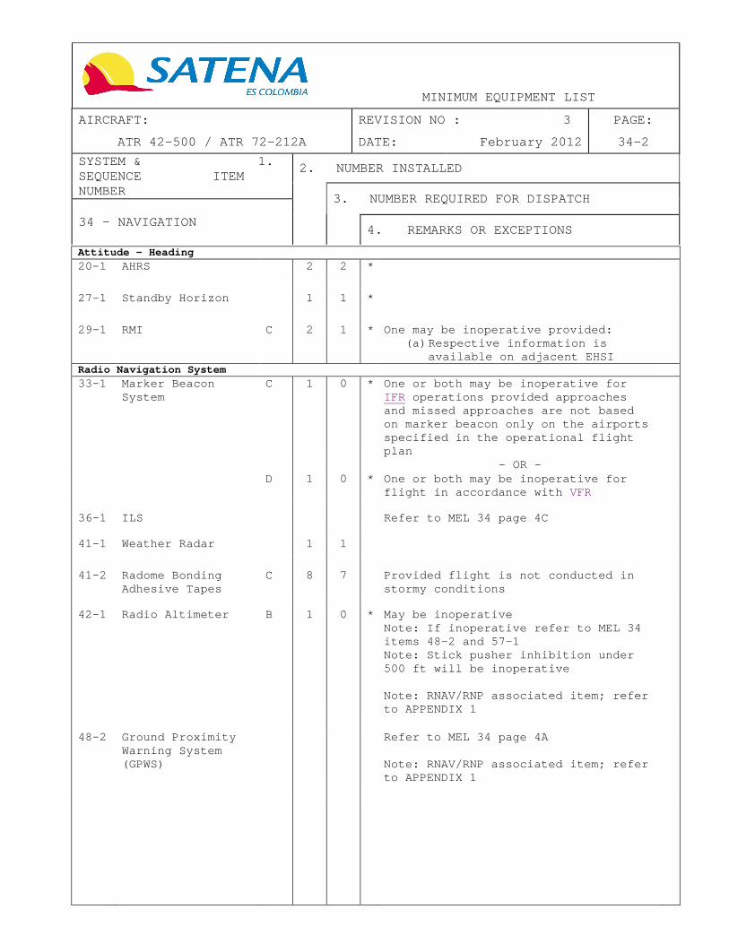
MINIMUM EQUIPMENT LIST
AIRCRAFT: REVISION NO : 3 PAGE:
ATR 42-500 / ATR 72-212A DATE: February 2012 34-2
SYSTEM & 1. SEQUENCE ITEM NUMBER
2. NUMBER INSTALLED
3. NUMBER REQUIRED FOR DISPATCH
34 - NAVIGATION
4. REMARKS OR EXCEPTIONS
Attitude – Heading
20-1 AHRS 2 2 *
27-1 Standby Horizon 1 1 *
29-1 RMI C 2 1 * One may be inoperative provided:
(a) Respective information is available on adjacent EHSI
Radio Navigation System
33-1 Marker Beacon System
C 1 0 * One or both may be inoperative for IFR operations provided approaches and missed approaches are not based on marker beacon only on the airports specified in the operational flight plan
- OR - D 1 0 * One or both may be inoperative for
flight in accordance with VFR
36-1 ILS Refer to MEL 34 page 4C 41-1 Weather Radar 1 1
41-2 Radome Bonding
Adhesive Tapes C 8 7 Provided flight is not conducted in
stormy conditions
42-1 Radio Altimeter B 1 0 * May be inoperative
Note: If inoperative refer to MEL 34 items 48-2 and 57-1 Note: Stick pusher inhibition under 500 ft will be inoperative Note: RNAV/RNP associated item; refer to APPENDIX 1
48-2 Ground Proximity Warning System (GPWS)
Refer to MEL 34 page 4A Note: RNAV/RNP associated item; refer to APPENDIX 1

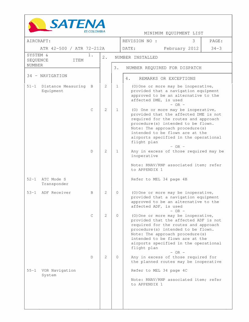
MINIMUM EQUIPMENT LIST
AIRCRAFT: REVISION NO : 3 PAGE:
ATR 42-500 / ATR 72-212A DATE: February 2012 34-3
SYSTEM & 1. SEQUENCE ITEM NUMBER
2. NUMBER INSTALLED
3. NUMBER REQUIRED FOR DISPATCH
34 - NAVIGATION
4. REMARKS OR EXCEPTIONS
51-1 Distance Measuring Equipment
B 2 1 (O)One or more may be inoperative, provided that a navigation equipment approved to be an alternative to the affected DME, is used
- OR - C 2 1 (O) One or more may be inoperative,
provided that the affected DME is not required for the routes and approach procedure(s) intended to be flown. Note: The approach procedure(s) intended to be flown are at the airports specified in the operational flight plan
- OR - D 2 1 Any in excess of those required may be
inoperative Note: RNAV/RNP associated item; refer to APPENDIX 1
52-1 ATC Mode S Transponder
Refer to MEL 34 page 4B
53-1 ADF Receiver B 2 0 (O)One or more may be inop erative,
provided that a navigation equipment approved to be an alternative to the affected ADF, is used
- OR - C 2 0 (O)One or more may be inoperative,
provided that the affected ADF is not required for the routes and approach procedure(s) intended to be flown. Note: The approach procedure(s) intended to be flown are at the airports specified in the operational flight plan
- OR - D 2 0 Any in excess of those required for
the planned routes may be inoperative
55-1 VOR Navigation
System Refer to MEL 34 page 4C
Note: RNAV/RNP associated item; refer to APPENDIX 1

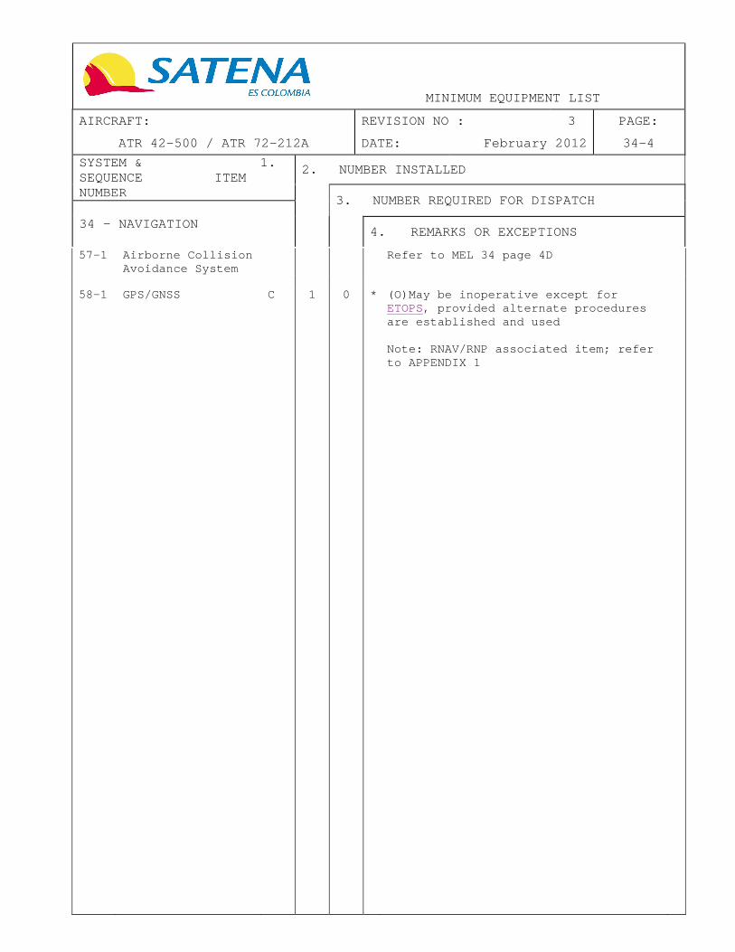
MINIMUM EQUIPMENT LIST
AIRCRAFT: REVISION NO : 3 PAGE:
ATR 42-500 / ATR 72-212A DATE: February 2012 34-4
SYSTEM & 1. SEQUENCE ITEM NUMBER
2. NUMBER INSTALLED
3. NUMBER REQUIRED FOR DISPATCH
34 - NAVIGATION
4. REMARKS OR EXCEPTIONS
57-1 Airborne Collision Avoidance System
Refer to MEL 34 page 4D
58-1 GPS/GNSS C 1 0 * (O)May be inoperative except for
ETOPS, provided alternate procedures are established and used Note: RNAV/RNP associated item; refer to APPENDIX 1

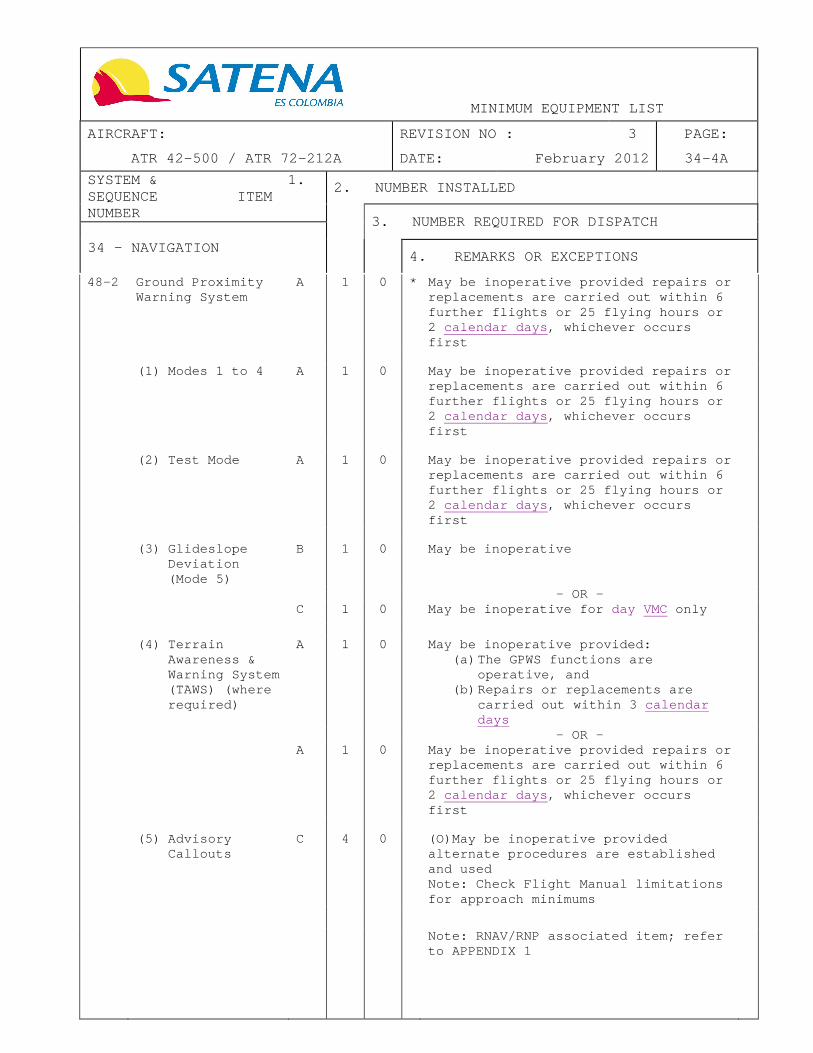
MINIMUM EQUIPMENT LIST
AIRCRAFT: REVISION NO : 3 PAGE:
ATR 42-500 / ATR 72-212A DATE: February 2012 34-4A
SYSTEM & 1. SEQUENCE ITEM NUMBER
2. NUMBER INSTALLED
3. NUMBER REQUIRED FOR DISPATCH
34 - NAVIGATION
4. REMARKS OR EXCEPTIONS
48-2 Ground Proximity Warning System
A 1 0 * May be inoperative provided repa irs or replacements are carried out within 6 further flights or 25 flying hours or 2 calendar days , whichever occurs first
(1) Modes 1 to 4 A 1 0 May be inoperative provided repairs or
replacements are carried out within 6 further flights or 25 flying hours or 2 calendar days , whichever occurs first
(2) Test Mode A 1 0 May be inoperative provided repairs or
replacements are carried out within 6 further flights or 25 flying hours or 2 calendar days , whichever occurs first
(3) Glideslope
Deviation (Mode 5)
B 1 0 May be inoperative
- OR - C 1 0 May be inoperative for day VMC only
(4) Terrain
Awareness & Warning System (TAWS) (where required)
A 1 0 May be inoperative provided: (a) The GPWS functions are
operative, and (b) Repairs or replacements are
carried out within 3 calendar days
- OR - A 1 0 May be inoperative provided repairs or
replacements are carried out within 6 further flights or 25 flying hours or 2 calendar days , whichever occurs first
(5) Advisory
Callouts C 4 0 (O)May be inoperative provided
alternate procedures are established and used Note: Check Flight Manual limitations for approach minimums
Note: RNAV/RNP associated item; refer to APPENDIX 1


MINIMUM EQUIPMENT LIST
AIRCRAFT: REVISION NO : 3 PAGE:
ATR 42-500 / ATR 72-212A DATE: February 2012 34-4B
SYSTEM & 1. SEQUENCE ITEM NUMBER
2. NUMBER INSTALLED
3. NUMBER REQUIRED FOR DISPATCH
34 - NAVIGATION
4. REMARKS OR EXCEPTIONS
Note: An operativ e ATC Mode S Transponder is defined as a transponde r that can provide at least Elementary Surveillance Capability
52-1 ATC Mode S Transponder System
D 2 1 Any in excess of those required for the intended route may be inoperative Note: the intended route includes all the airports specified in the operational flight plan
- OR -
C 2 1 One or more may be inoperative provided permission is obtained from the Air Navigation Service Provider(s) when required for the intended route or airport(s). Note: Altitude reporting, provided by an ATC Mode S Transponder, is required for ACAS II operation. Refer to MEL 34 page 4D item 57-1
(1) Enhanced Surveillance Capability
C 1 0 One or more Downlinked Aircraft Parameters, which provide Enhanced Surveillance, may be inoperative when required for the intended route

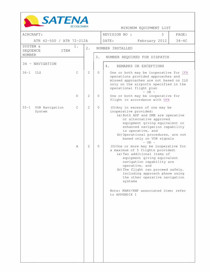
MINIMUM EQUIPMENT LIST
AIRCRAFT: REVISION NO : 3 PAGE:
ATR 42-500 / ATR 72-212A DATE: February 2012 34-4C
SYSTEM & 1. SEQUENCE ITEM NUMBER
2. NUMBER INSTALLED
3. NUMBER REQUIRED FOR DISPATCH
34 - NAVIGATION
4. REMARKS OR EXCEPTIONS
36-1 ILS C 2 0 One or both may be inoperative for IFR operations provided approaches and missed approaches are not based on ILS only on the airports specified in the operational flight plan
- OR - D 2 0 One or both may be inoperative for
flight in accordance with VFR
55-1 VOR Navigation System
C 2 0 (O)Any in excess of one may be inoperative provided:
(a) Both ADF and DME are operative or alternative approved equipment giving equivalent or enhanced navigation capability is operative, and
(b) Operational procedures, are not based only on VOR signals
- OR - A 2 0 (O)One or more may be inoperative for
a maximum of 5 flights provided: (a) Two additional items of
equipment giving equivalent navigation capability are operative, and
(b) The flight can proceed safely, including approach phase using the other operative navigation systems
Note: RNAV/RNP associated item; refer to APPENDIX 1

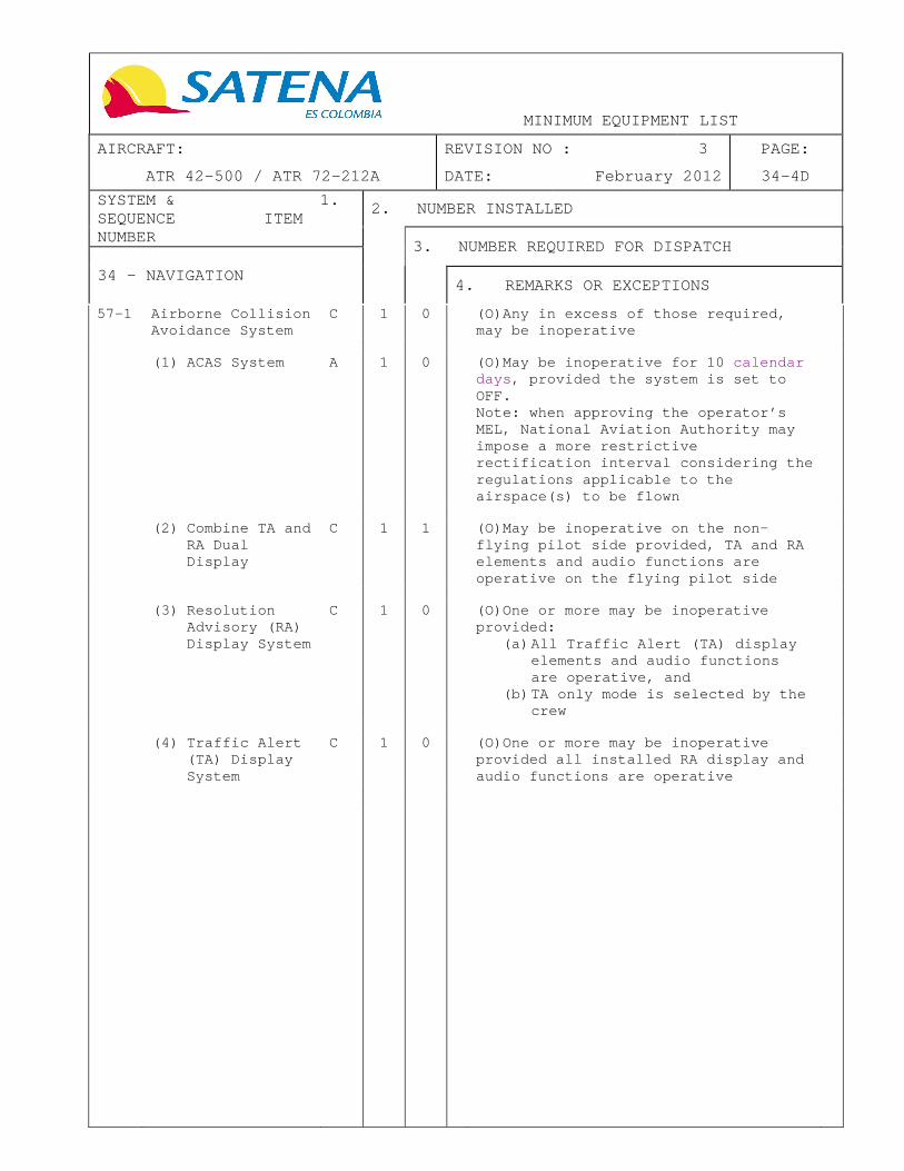
MINIMUM EQUIPMENT LIST
AIRCRAFT: REVISION NO : 3 PAGE:
ATR 42-500 / ATR 72-212A DATE: February 2012 34-4D
SYSTEM & 1. SEQUENCE ITEM NUMBER
2. NUMBER INSTALLED
3. NUMBER REQUIRED FOR DISPATCH
34 - NAVIGATION
4. REMARKS OR EXCEPTIONS
57-1 Airborne Collision Avoidance System
C 1 0 (O)Any in excess of those required, may be inoperative
(1) ACAS System A 1 0 (O)May be inoperative for 10 calendar
days , provided the system is set to OFF. Note: when approving the operator’s MEL, National Aviation Authority may impose a more restrictive rectification interval considering the regulations applicable to the airspace(s) to be flown
(2) Combine TA and
RA Dual Display
C 1 1 (O)May be inoperative on the non-flying pilot side provided, TA and RA elements and audio functions are operative on the flying pilot side
(3) Resolution
Advisory (RA) Display System
C 1 0 (O)One or more may be inoperative provided:
(a) All Traffic Alert (TA) display elements and audio functions are operative, and
(b) TA only mode is selected by the crew
(4) Traffic Alert
(TA) Display System
C 1 0 (O)One or more may be inoperative provided all installed RA display and audio functions are operative

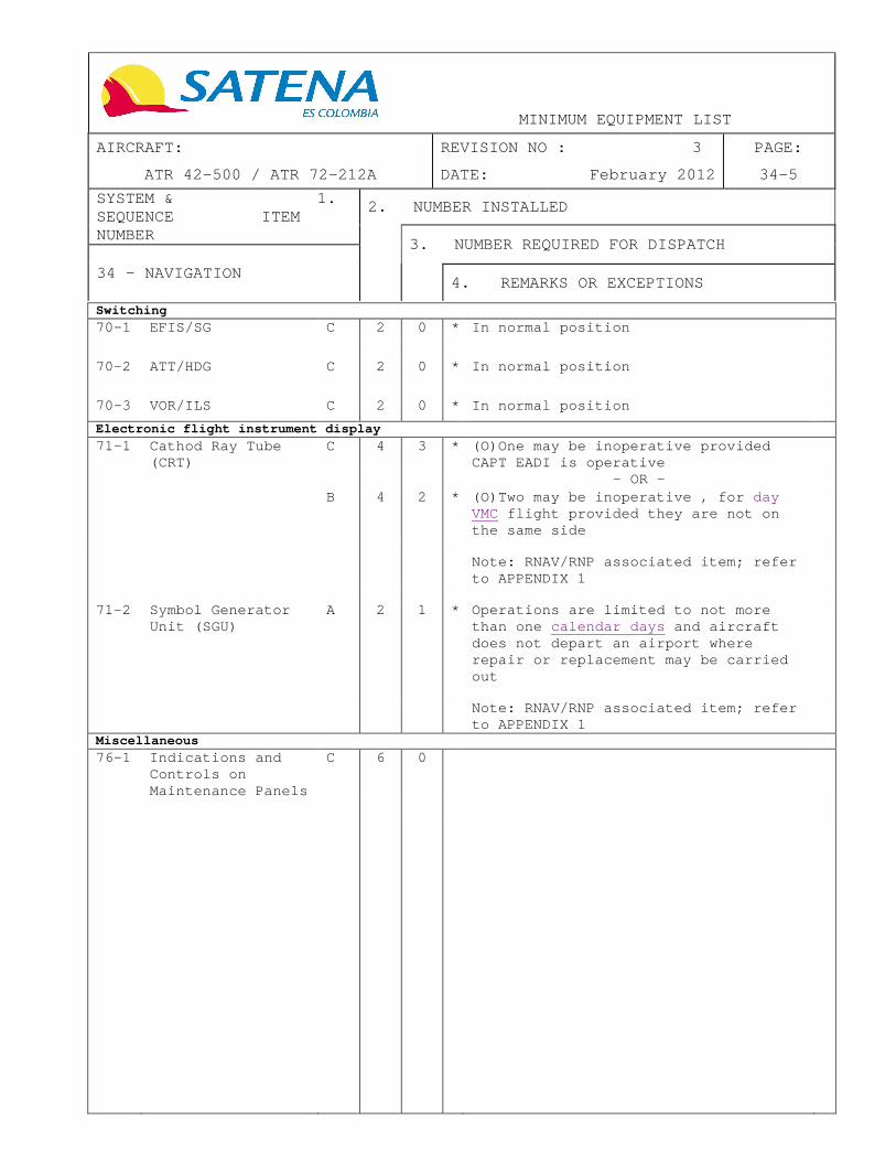
MINIMUM EQUIPMENT LIST
AIRCRAFT: REVISION NO : 3 PAGE:
ATR 42-500 / ATR 72-212A DATE: February 2012 34-5
SYSTEM & 1. SEQUENCE ITEM NUMBER
2. NUMBER INSTALLED
3. NUMBER REQUIRED FOR DISPATCH
34 - NAVIGATION
4. REMARKS OR EXCEPTIONS
Switching
70-1 EFIS/SG C 2 0 * In normal position
70-2 ATT/HDG C 2 0 * In normal position
70-3 VOR/ILS C 2 0 * In normal position
Electronic flight instrument display
71-1 Cathod Ray Tube (CRT)
C 4 3 * (O)One may be inoperative provided CAPT EADI is operative
- OR - B 4 2 * (O)Two may be inoperative , for day
VMC flight provided they are not on the same side
Note: RNAV/RNP associated item; refer
to APPENDIX 1
71-2 Symbol Generator
Unit (SGU) A 2 1 * Operations are limited to not more
than one calendar days and aircraft does not depart an airport where repair or replacement may be carried out
Note: RNAV/RNP associated item; refer
to APPENDIX 1
Miscellaneou s
76-1 Indications and Controls on Maintenance Panels
C 6 0

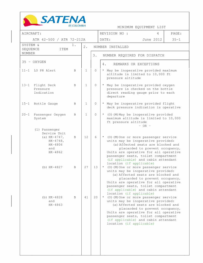
MINIMUM EQUIPMENT LIST
AIRCRAFT: REVISION NO : 4 PAGE:
ATR 42-500 / ATR 72-212A DATE: June 2012 35-1
SYSTEM & 1. SEQUENCE ITEM NUMBER
2. NUMBER INSTALLED
3. NUMBER REQUIRED FOR DISPATCH
35 - OXYGEN
4. REMARKS OR EXCEPTIONS
11-1 LO PR Alert B 1 0 * May be inoperative provided maximum altitude is limited to 10,000 ft pressure altitude
13-1 Flight Deck
Pressure Indication
B 1 0 * May be inoperative provided oxygen pressure is checked on the bottle direct reading gauge prior to each departure
15-1 Bottle Gauge B 1 0 * May be inoperative provided flight
deck pressure indication is operative
20-1 Passenger Oxygen
System B 1 0 * (O)(M)May be inoperative provided
maximum altitude is limited to 10,000 ft pressure altitude
- OR - (1) Passenger
Service Unit
(a) HK-4747, HK-4748, HK-4806 and HK-4862
B 12 6 * (O)(M)One or more passenger service units may be inoperative provided:
(a) Affected seats are blocked and placarded to prevent occupancy,
Units are operative for all operative passenger seats, toilet compartment (if applicable) and cabin attendant location (if applicable)
(b) HK-4827 B 27 13 * (O)(M)One or more passenger service units may be inoperative provided:
(a) Affected seats are blocked and placarded to prevent occupancy,
Units are operative for all operative passenger seats, toilet compartment (if applicable) and cabin attendant location (if applicable)
(b) HK-4828 and HK-4863
B 41 20 * (O)(M)One or more passenger service units may be inoperative provided:
(a) Affected seats are blocked and placarded to prevent occupancy,
Units are operative for all operative passenger seats, toilet compartment (if applicable) and cabin attendant location (if applicable)

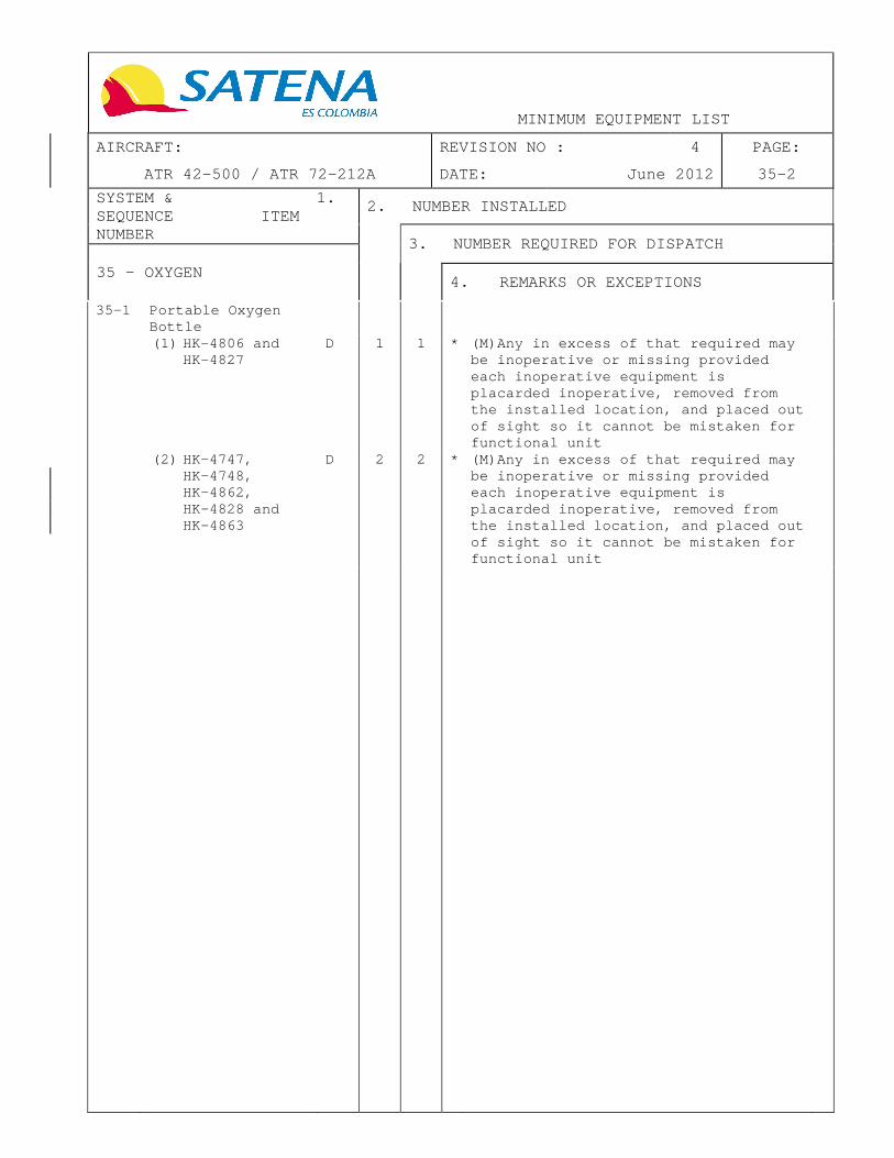
MINIMUM EQUIPMENT LIST
AIRCRAFT: REVISION NO : 4 PAGE:
ATR 42-500 / ATR 72-212A DATE: June 2012 35-2
SYSTEM & 1. SEQUENCE ITEM NUMBER
2. NUMBER INSTALLED
3. NUMBER REQUIRED FOR DISPATCH
35 - OXYGEN
4. REMARKS OR EXCEPTIONS
35-1 Portable Oxygen Bottle
(1) HK-4806 and HK-4827
D 1 1 * (M)Any in excess of that required may be inoperative or missing provided each inoperative equipment is placarded inoperative, removed from the installed location, and placed out of sight so it cannot be mistaken for functional unit
(2) HK-4747, HK-4748, HK-4862, HK-4828 and HK-4863
D 2 2 * (M)Any in excess of that required may be inoperative or missing provided each inoperative equipment is placarded inoperative, removed from the installed location, and placed out of sight so it cannot be mistaken for functional unit

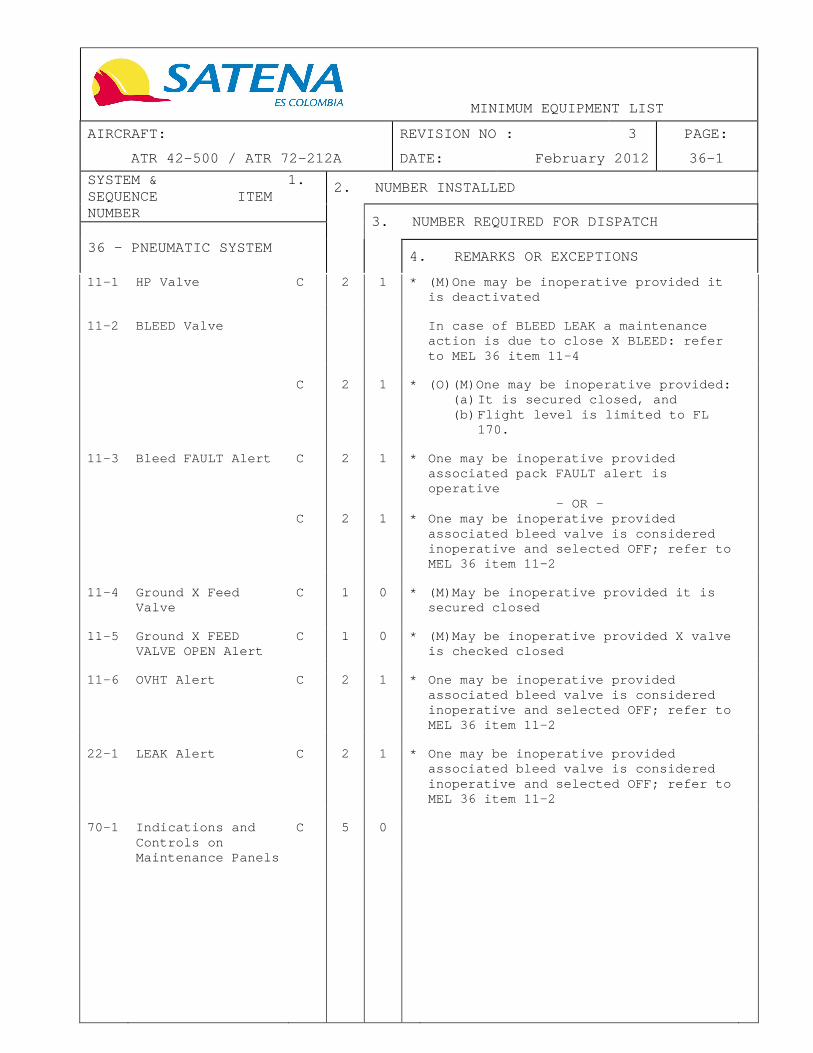
MINIMUM EQUIPMENT LIST
AIRCRAFT: REVISION NO : 3 PAGE:
ATR 42-500 / ATR 72-212A DATE: February 2012 36-1
SYSTEM & 1. SEQUENCE ITEM NUMBER
2. NUMBER INSTALLED
3. NUMBER REQUIRED FOR DISPATCH
36 – PNEUMATIC SYSTEM
4. REMARKS OR EXCEPTIONS
11-1 HP Valve C 2 1 * (M)One may be inoperative provided it is deactivated
11-2 BLEED Valve In case of BLEED LEAK a mainte nance
action is due to close X BLEED: refer to MEL 36 item 11-4
C 2 1 * (O)(M)One may be inoperative provided:
(a) It is secured closed, and (b) Flight level is limited to FL
170.
11-3 Bleed FAULT Alert C 2 1 * One may be inoperative provided
associated pack FAULT alert is operative
- OR - C 2 1 * One may be inoperative provided
associated bleed valve is considered inoperative and selected OFF; refer to MEL 36 item 11-2
11-4 Ground X Feed
Valve C 1 0 * (M)May be inoperative provided it is
secured closed
11-5 Ground X FEED
VALVE OPEN Alert C 1 0 * (M)May be inoperative provided X valve
is checked closed
11-6 OVHT Alert C 2 1 * One may be inoperative provided
associated bleed valve is considered inoperative and selected OFF; refer to MEL 36 item 11-2
22-1 LEAK Alert C 2 1 * One may be inoperative provided
associated bleed valve is considered inoperative and selected OFF; refer to MEL 36 item 11-2
70-1 Indications and
Controls on Maintenance Panels
C 5 0


MINIMUM EQUIPMENT LIST
AIRCRAFT: REVISION NO : 3 PAGE:
ATR 42-500 / ATR 72-212A DATE: February 2012 52-1
SYSTEM & 1. SEQUENCE ITEM NUMBER
2. NUMBER INSTALLED
3. NUMBER REQUIRED FOR DISPATCH
52 – DOORS
4. REMARKS OR EXCEPTIONS
11-1 Door Alert System
(1) B 1 0 * (M)May be inoperative provided affected doors are checked locked closed prior to each flight
12-1 Passenger Door
Torque Tube
(1) A 1 0 * May be inoperative for one ferry flight to a base where repair is possible provided:
(a) Ground personnel assistance for opening and closing operation is available, and
(b) Door is not operated from inside the aircraft (except in case of emergency), and
(c) It is checked that nobody is right below the door during the operation, and
(d) All possibly concerned personnel are informed about the unbalanced condition
21-1 Emergency Exit Refer to MEL 52 page 2 for this item
31-1 Cargo Door Motor
Actuator C 1 0 (M)May be inoperative provided an
approved mechanical device (crank) installed in the aircraft is used for cargo door operation
- OR - C 1 0 An alternate way is defined to
load/unload the forward cargo
31-2 Cargo Door Control
System C 1 0 * May be inoperative provided cargo door
is visually checked locked closed
31-3 AUX AFT Cargo Door
(“Class C”) (if installed)
NOT APPLICABLE


MINIMUM EQUIPMENT LIST
AIRCRAFT: REVISION NO : 3 PAGE:
ATR 42-500 / ATR 72-212A DATE: February 2012 52-2
SYSTEM & 1. SEQUENCE ITEM NUMBER
2. NUMBER INSTALLED
3. NUMBER REQUIRED FOR DISPATCH
52 – DOORS
4. REMARKS OR EXCEPTIONS
42-1 Service Door – Hold Open Device
(1) C 1 0 (M)In case of cable failure provided the approved mechanical device to maintain the hook open is installed
21-1 Emergency Exit
(including passenger/crew doors, but excluding flight deck emergency exits)
(1) Passenger A 4 1 One may be inoperative for a maxim um of 5 flights provided:
(a) The passenger number reduction and distribution policy, and cabin safety procedures are established and used, and
(b) The affected emergency exit is closed and locked, and
(c) A conspicuous barrier, strap or rope and a placard stating “DO NOT USE” are placed across the affected emergency exit prior to passenger boarding, and
(d) The affected emergency exit is not used for passenger boarding, nor for any purpose whilst passengers are on board, and
(e) Visual indications (illuminated and non-illuminated) directing passengers to the affected emergency exit are obscured, and
(Continued)


MINIMUM EQUIPMENT LIST
AIRCRAFT: REVISION NO : 3 PAGE:
ATR 42-500 / ATR 72-212A DATE: February 2012 52-3
SYSTEM & 1. SEQUENCE ITEM NUMBER
2. NUMBER INSTALLED
3. NUMBER REQUIRED FOR DISPATCH
52 – DOORS
4. REMARKS OR EXCEPTIONS
21-1 Emergency Exit (including passenger/crew doors, but excluding flight deck emergency exits) (Cont'd)
(1) Passenger (f) All crew members are briefed on the location and condition of the affected emergency exit, passenger distribution and modified cabin safety procedures, and
(g) The affected emergency exit and blocked seating layout are checked before each flight by the relevant cabin crew member, and
(h) The escape path to the affected emergency exit is checked by the relevant cabin crew member to be unobstructed before each take off and landing, and
(i) Extended overwater flight is prohibited
Note: If the affected emergency exit is operative mechanically, it may still be used for evacuation in the case of emergency
50-1 Cockpit Door Locking System (if installed)
* (O) Note: any part of the CDLS may be inoperative provided the complete system is deactivated in the unlocked position and is not required by operational regulations for the intended flight
(1) System (Control Unit, Toggle Switch, Lights on Control Panel, Buzzer)
A 1 0 * (O) Provided operatio ns are limited to not more than two calendar days
(2) Call Pushbutton on Door Call Panel
C 1 0 * Provided the crew members interphone is operative
(Continued)


MINIMUM EQUIPMENT LIST
AIRCRAFT: REVISION NO : 3 PAGE:
ATR 42-500 / ATR 72-212A DATE: February 2012 52-4
SYSTEM & 1. SEQUENCE ITEM NUMBER
2. NUMBER INSTALLED
3. NUMBER REQUIRED FOR DISPATCH
52 – DOORS
4. REMARKS OR EXCEPTIONS
50-1 Cockpit Door Locking System (if installed) (Cont'd)
(3) EMER Pushbutton on Door Call Panel
C 1 0 * (O) Provided the crew members interphone is operative
(4) OPEN Light on Door Call Panel
C 1 0 *
(5) DENY Light on Door Call Panel
C 1 0 * Provided the crew members interphone is operative


MINIMUM EQUIPMENT LIST
AIRCRAFT: REVISION NO : 4 PAGE:
ATR 42-500 / ATR 72-212A DATE: June 2012 56-1
SYSTEM & 1. SEQUENCE ITEM NUMBER
2. NUMBER INSTALLED
3. NUMBER REQUIRED FOR DISPATCH
56 – WINDOWS
4. REMARKS OR EXCEPTIONS
11-1 Windshield (Including Main Windshield, Forward and After Side Windows)
Caution: A cockpit window with minor damages, as described in SRM ref 56-10-00, is considered operative, but the vision through this cockpit wind ow must be acceptable to the pilot
C 6 6 (M)External ply may be cracked,
provided vision is not unacceptably impaired. In addition, for after side windows crack, refer to DDG 56 for this item
- OR - A 6 6 (M)Provided:
(a) Structural damages are accepted for non pressurized flight provided vision is not unacceptably impaired, and
(b) Operations are limited to not more than one calendar days
21-1 Passenger
Compartment Window
(1) Passenger Configuration
(a) HK-4747, HK-4748, HK-4806, HK-4827 and HK-4862
A 35 5 (M)Provided: (a) One or more cabin windows may be
cracked provided the flight is conducted unpressurized, and
Operations are limited to not more than one calendar day
(b) HK-4828 and HK-4863
A 51 8 (M)Provided: (a) One or more cabin windows may be
cracked provided the flight is conducted unpressurized, and
Operations are limited to not more than one calendar day

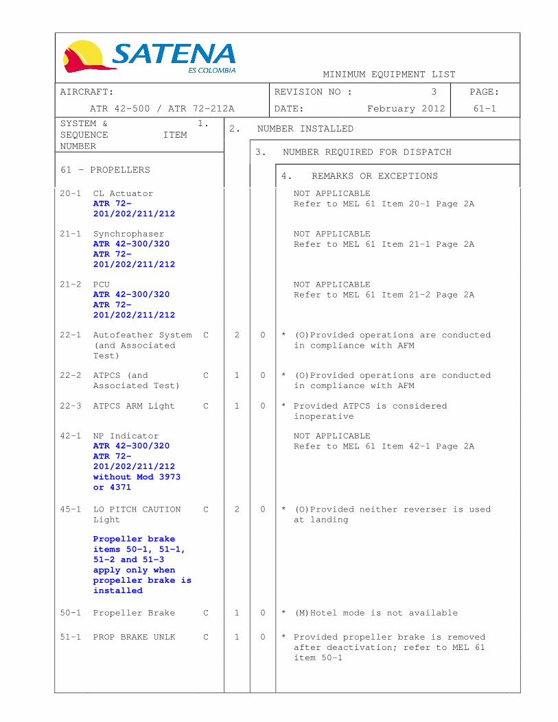
MINIMUM EQUIPMENT LIST
AIRCRAFT: REVISION NO : 3 PAGE:
ATR 42-500 / ATR 72-212A DATE: February 2012 61-1
SYSTEM & 1. SEQUENCE ITEM NUMBER
2. NUMBER INSTALLED
3. NUMBER REQUIRED FOR DISPATCH
61 – PROPELLERS
4. REMARKS OR EXCEPTIONS
20-1 CL Actuator ATR 72-201/202/211/212
NOT APPLICABLE Refer to MEL 61 Item 20-1 Page 2A
21-1 Synchrophaser
ATR 42-300/320 ATR 72- 201/202/211/212
NOT APPLICABLE Refer to MEL 61 Item 21-1 Page 2A
21-2 PCU
ATR 42-300/320 ATR 72-201/202/211/212
NOT APPLICABLE Refer to MEL 61 Item 21-2 Page 2A
22-1 Autofeather System
(and Associated Test)
C 2 0 * (O)Provided operations are conducted in compliance with AFM
22-2 ATPCS (and
Associated Test) C 1 0 * (O)Provided operations are conducted
in compliance with AFM
22-3 ATPCS ARM Light C 1 0 * Provided ATPCS is considered inoperative
42-1 NP Indicator
ATR 42-300/320 ATR 72-201/202/211/212 without Mod 3973 or 4371
NOT APPLICABLE Refer to MEL 61 Item 42-1 Page 2A
45-1 LO PITCH CAUTION Light
C 2 0 * (O)Provided neither reverser is used at landing
Propeller brake
items 50-1, 51-1, 51-2 and 51-3 apply only when propeller brake is installed
50-1 Propeller Brake C 1 0 * (M)Hotel mode is not available
51-1 PROP BRAKE UNLK C 1 0 * Provided propeller brake is removed
after deactivation; refer to MEL 61 item 50-1

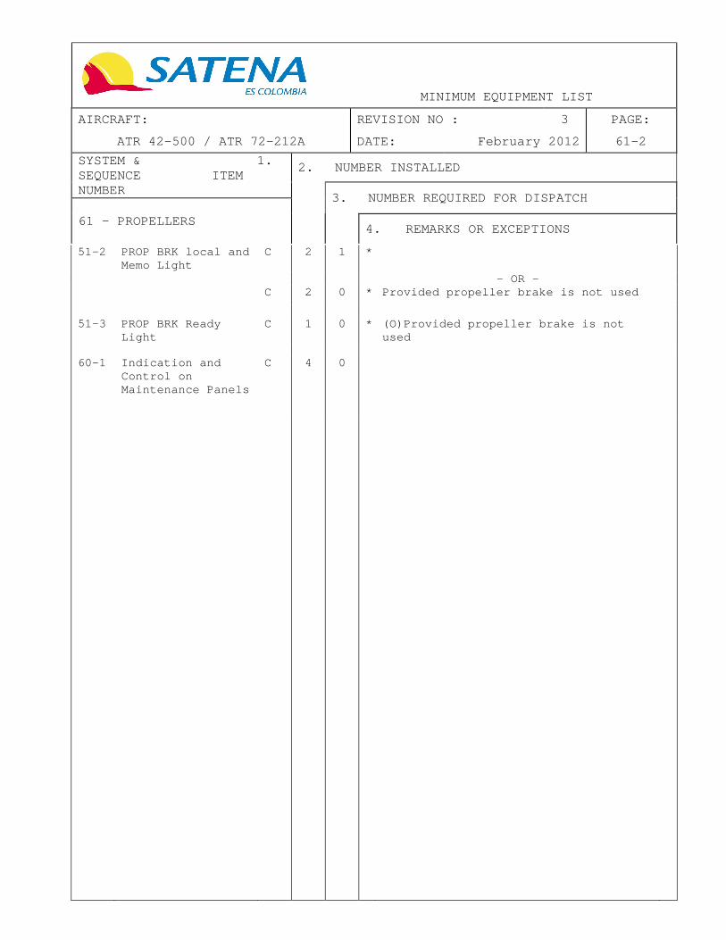
MINIMUM EQUIPMENT LIST
AIRCRAFT: REVISION NO : 3 PAGE:
ATR 42-500 / ATR 72-212A DATE: February 2012 61-2
SYSTEM & 1. SEQUENCE ITEM NUMBER
2. NUMBER INSTALLED
3. NUMBER REQUIRED FOR DISPATCH
61 – PROPELLERS
4. REMARKS OR EXCEPTIONS
51-2 PROP BRK local and Memo Light
C 2 1 *
- OR - C 2 0 * Provided propeller brake is not used
51-3 PROP BRK Ready
Light C 1 0 * (O)Provided propeller brake is not
used
60-1 Indication and
Control on Maintenance Panels
C 4 0


MINIMUM EQUIPMENT LIST
AIRCRAFT: REVISION NO : 3 PAGE:
ATR 42-500 / ATR 72-212A DATE: February 2012 61-2A
SYSTEM & 1. SEQUENCE ITEM NUMBER
2. NUMBER INSTALLED
3. NUMBER REQUIRED FOR DISPATCH
61 – PROPELLERS
4. REMARKS OR EXCEPTIONS
20-1 CL Actuator NOT APPLICABLE
21-1 PEC Channel A 4 2 * (O)Two may be inoperative provided: (a) One channel is operative on each
engine, and (b) Reversers are not used when
operated on narrow runways (width < 30 m (98 ft)), and
(c) Operations are limited to not more than two calendar days
21-2 PEC SGL CH Light A 2 0 * (O)May be inoperative provided:
(a) PEC channel is considered inoperative on affected engine: refer to MEL 61 item 21-1, and
(b) Operations are limited to not more than two calendar days
21-3 APC
ATR 72-202/212 with mod 4408
NOT APPLICABLE
21-4 PIU and Associated
Propeller Speed Selection
C 2 0 (O)May be inoperative provided both CL are set to 100% OVRD Note: if affected side cannot be identified, both PIU should be considered as inoperative
42-1 NP Indicator C 2 2 * (M)Either pointer or counter may be
inoperative on each indicator provided associated PROP anti icing is operative
- OR - C 2 1 * (O)One may be inoperative except for
ETOPS provided aircraft is not operated into known or forecast icing conditions


MINIMUM EQUIPMENT LIST
AIRCRAFT: REVISION NO : 3 PAGE:
ATR 42-500 / ATR 72-212A DATE: February 2012 73-1
SYSTEM & 1. SEQUENCE ITEM NUMBER
2. NUMBER INSTALLED
3. NUMBER REQUIRED FOR DISPATCH
73 – ENGINE FUEL AND CONTROL
4. REMARKS OR EXCEPTIONS
13-1 IDLE GATE FAIL Alert
C 1 0 * (O)
15-1 Fuel Heater C 2 0 * (M) If the reported fuel temperature is too low and SAT cannot be maintained above 0°C during the flight:
(a) Refer to maintenance procedure before any refueling, and
(b) Check engine oil level before the first flight of each day
- OR - C 2 0 * (M) If the reported fuel temperature is
too high: refer to maintenance procedure before any refueling
23-1 PWR MGT Rotary
Selector A 2 1 * (O)One may be inoperative provided
operations are limited to not more than two calendar days
23-2 EEC A 2 1 * (O)One may be inoperative provided:
(a) DC HYD pump is operative, and (b) Operations are conducted in
compliance with AFM, and (c) Operations are limited to not
more than two calendar days, and (d) Associated pack and bleed valve
are operative
23-3 Uptrim (and
Associated Test) C 2 0 * (O)Both may be inoperative
23-4 UPTRIM Light C 2 0 * (O)One or more may be inoperative
provided uptrim is considered inoperative; refer to MEL 73 item 23-3
23-5 ERIU (if
installed) Aircraft fitted with PW127M
NOT APPLICABLE
23-6 Boost Function (if
installed) NOT APPLICABLE
31-1 Fuel Flow
Indicator B 2 1 * One may be inoperative
31-2 Fuel Used C 2 1 * One may be inoperative provided associated tank fuel QTY indicator is operative


MINIMUM EQUIPMENT LIST
AIRCRAFT: REVISION NO : 3 PAGE:
ATR 42-500 / ATR 72-212A DATE: February 2012 73-2
SYSTEM & 1. SEQUENCE ITEM NUMBER
2. NUMBER INSTALLED
3. NUMBER REQUIRED FOR DISPATCH
73 – ENGINE FUEL AND CONTROL
4. REMARKS OR EXCEPTIONS
34-1 Fuel Clog A 2 1 * One may be inoperative provided: (a) Associated engine parameters are
monitored during the flight, and
(b) Operations are limited to not more than one calendar day and aircraft does not depart an airport where repair or replacement may be carried out
35-1 Fuel Temperature
Indication C 2 0 * May be inoperative provided associated
fuel heater is considered inoperative; refer to MEL 73 item 15-1
60-1 Indication and
Control on Maintenance Panels
C 2 0 May be inoperative

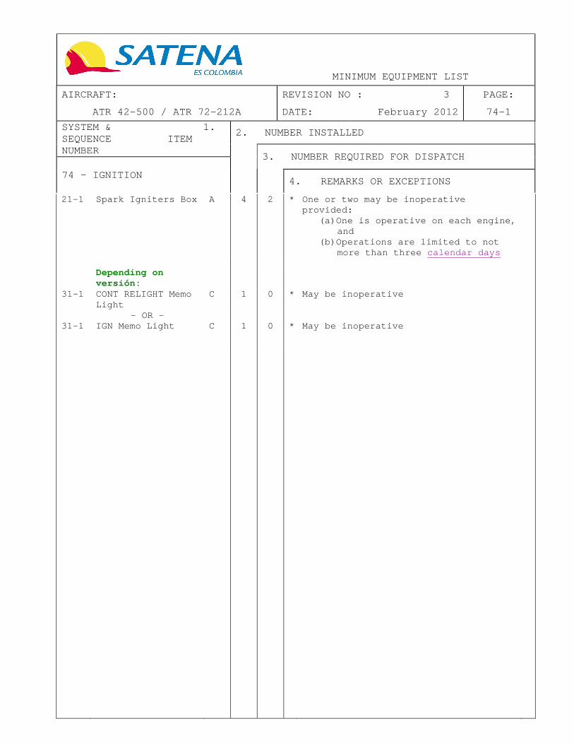
MINIMUM EQUIPMENT LIST
AIRCRAFT: REVISION NO : 3 PAGE:
ATR 42-500 / ATR 72-212A DATE: February 2012 74-1
SYSTEM & 1. SEQUENCE ITEM NUMBER
2. NUMBER INSTALLED
3. NUMBER REQUIRED FOR DISPATCH
74 – IGNITION
4. REMARKS OR EXCEPTIONS
21-1 Spark Igniters Box A 4 2 * One or two may be inoperative provided:
(a) One is operative on each engine, and
(b) Operations are limited to not more than three calendar days
Depending on
versión:
31-1 CONT RELIGHT Memo Light
C 1 0 * May be inoperative
- OR - 31-1 IGN Memo Light C 1 0 * May be inoperative

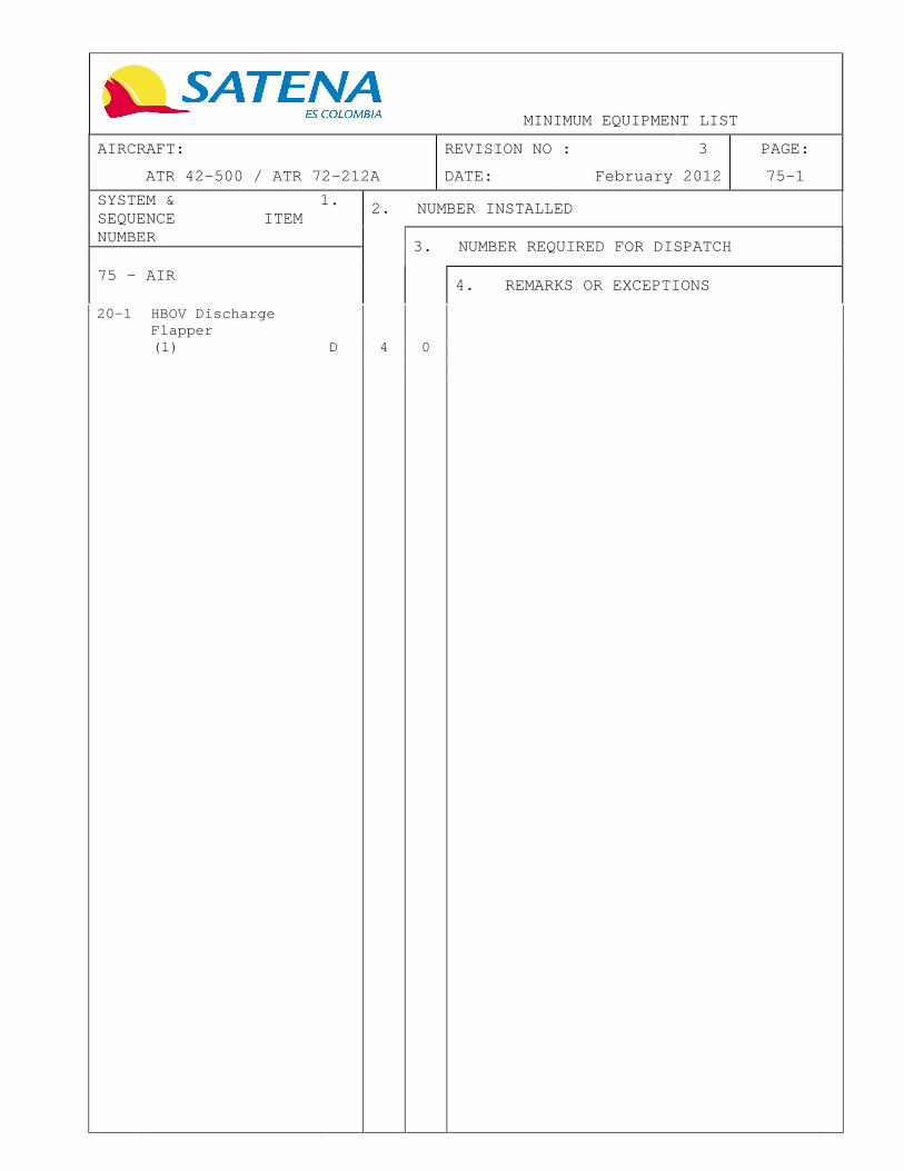
MINIMUM EQUIPMENT LIST
AIRCRAFT: REVISION NO : 3 PAGE:
ATR 42-500 / ATR 72-212A DATE: February 2012 75-1
SYSTEM & 1. SEQUENCE ITEM NUMBER
2. NUMBER INSTALLED
3. NUMBER REQUIRED FOR DISPATCH
75 – AIR
4. REMARKS OR EXCEPTIONS
20-1 HBOV Discharge Flapper
(1) D 4 0

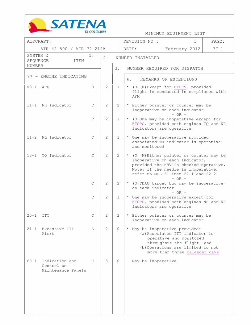
MINIMUM EQUIPMENT LIST
AIRCRAFT: REVISION NO : 3 PAGE:
ATR 42-500 / ATR 72-212A DATE: February 2012 77-1
SYSTEM & 1. SEQUENCE ITEM NUMBER
2. NUMBER INSTALLED
3. NUMBER REQUIRED FOR DISPATCH
77 – ENGINE INDICATING
4. REMARKS OR EXCEPTIONS
00-1 AFU B 2 1 * (O)(M)Except for ETOPS, provided flight is conducted in compliance with AFM
11-1 NH Indicator C 2 2 * Either pointer or counter may be
inoperative on each indicator
- OR - C 2 1 * (O)One may be inoperative except for
ETOPS, provided both engines TQ and NP indicators are operative
11-2 NL Indicator C 2 1 * One may be inoperative provided
associated NH indicator is operative and monitored
13-1 TQ Indicator C 2 2 * (O)(M)Either pointer or counter may be
inoperative on each indicator, provided the HBV is checked operative. Note: if the needle is inoperative, refer to MEL 61 item 22-1 and 22-2
- OR - C 2 2 * (O)FDAU target bug may be inoperative
on each indicator
- OR - C 2 1 * One may be inoperative except for
ETOPS, provided both engines NH and NP indicators are operative
20-1 ITT C 2 2 * Either pointer or counter may be
inoperative on each indicator
21-1 Excessive ITT
Alert A 2 0 * May be inoperative provided:
(a) Associated ITT indicator is operative and monitored throughout the flight, and
(b) Operations are limited to not more than three calendar days
60-1 Indication and
Control on Maintenance Panels
C 8 0 May be inoperative

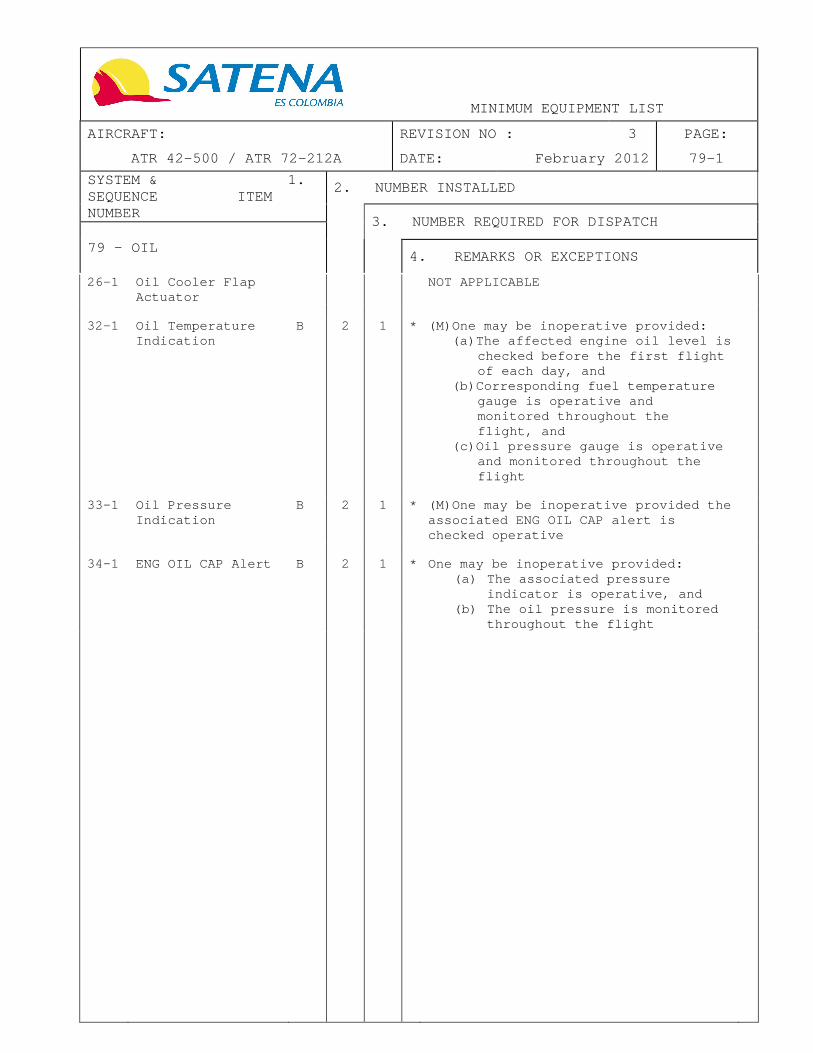
MINIMUM EQUIPMENT LIST
AIRCRAFT: REVISION NO : 3 PAGE:
ATR 42-500 / ATR 72-212A DATE: February 2012 79-1
SYSTEM & 1. SEQUENCE ITEM NUMBER
2. NUMBER INSTALLED
3. NUMBER REQUIRED FOR DISPATCH
79 – OIL
4. REMARKS OR EXCEPTIONS
26-1 Oil Cooler Flap Actuator
NOT APPLICABLE
32-1 Oil Temperature
Indication B 2 1 * (M)One may be inoperative provided:
(a) The affected engine oil level is checked before the first flight of each day, and
(b) Corresponding fuel temperature gauge is operative and monitored throughout the flight, and
(c) Oil pressure gauge is operative and monitored throughout the flight
33-1 Oil Pressure
Indication B 2 1 * (M)One may be inoperative provided the
associated ENG OIL CAP alert is checked operative
34-1 ENG OIL CAP Alert B 2 1 * One may be inoperative provided:
(a) The associated pressure indicator is operative, and
(b) The oil pressure is monitored throughout the flight

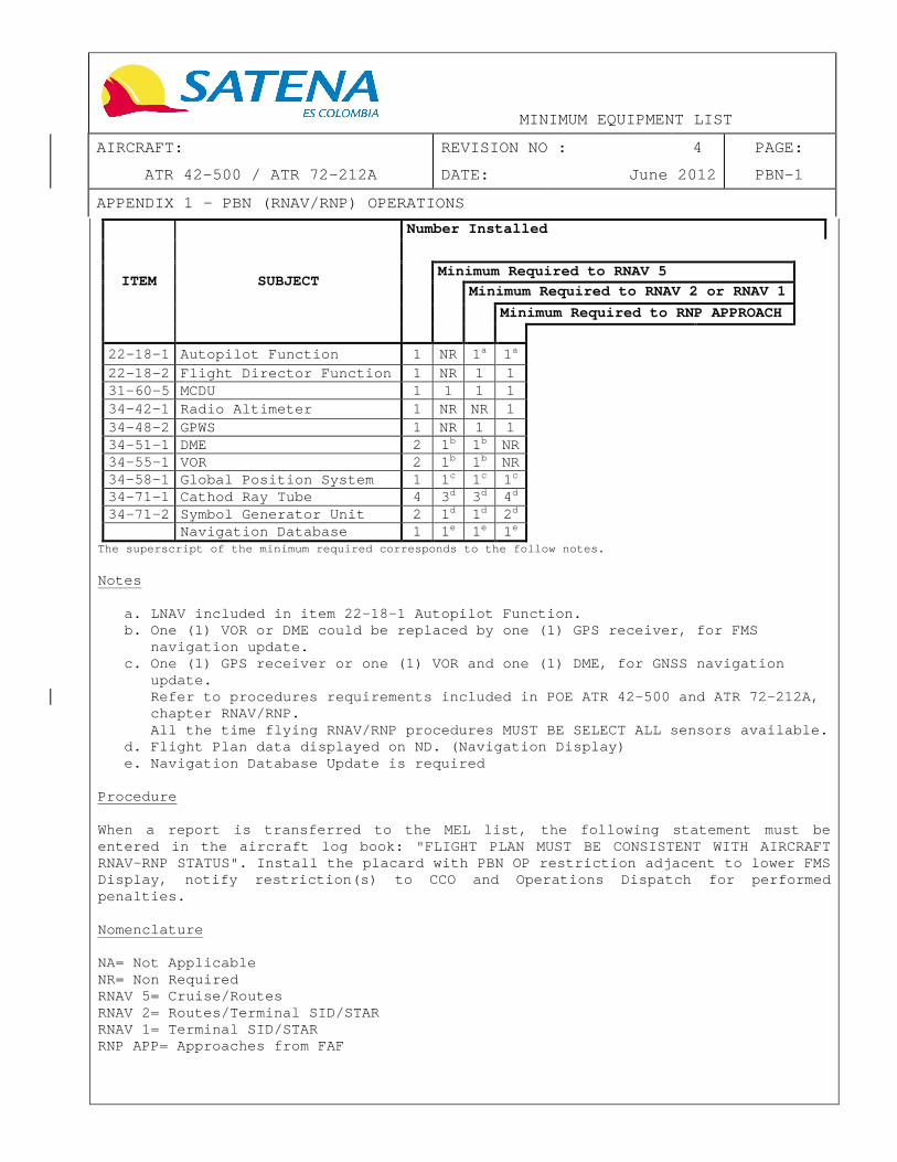
MINIMUM EQUIPMENT LIST
AIRCRAFT: REVISION NO : 4 PAGE:
ATR 42-500 / ATR 72-212A DATE: June 2012 PBN-1
APPENDIX 1 – PBN (RNAV/RNP) OPERATIONS
ITEM SUBJECT
Number Installed
Minimum Required to RNAV 5
Minimum Required to RNAV 2 or RNAV 1
Minimum Required to RNP APPROACH
22-18-1 Autopilot Function 1 NR 1a 1a 22-18-2 Flight Director Function 1 NR 1 1 31-60-5 MCDU 1 1 1 1 34-42-1 Radio Altimeter 1 NR NR 1 34-48-2 GPWS 1 NR 1 1 34-51-1 DME 2 1 b 1b NR 34-55-1 VOR 2 1 b 1b NR 34-58-1 Global Position System 1 1 c 1c 1c 34-71-1 Cathod Ray Tube 4 3 d 3d 4d 34-71-2 Symbol Generator Unit 2 1 d 1d 2d
Navigation Database 1 1 e 1e 1e
The superscript of the minimum required corresponds to the follow notes.
Notes
a. LNAV included in item 22-18-1 Autopilot Function. b. One (1) VOR or DME could be replaced by one (1) GPS receiver, for FMS
navigation update. c. One (1) GPS receiver or one (1) VOR and one (1) DME , for GNSS navigation
update. Refer to procedures requirements included in POE AT R 42-500 and ATR 72-212A, chapter RNAV/RNP. All the time flying RNAV/RNP procedures MUST BE SEL ECT ALL sensors available.
d. Flight Plan data displayed on ND. (Navigation Displ ay) e. Navigation Database Update is required
Procedure When a report i s transferred to the MEL list, the following statem ent must be entered in the aircraft log book: "FLIGHT PLAN MUST BE CONSISTENT WITH AIRCRAFT RNAV-RNP STATUS". Install the placard with PBN OP restri ction adjacent to lower FMS Display, notify restriction(s ) to CCO and Operations Dispatch for performed penalties. Nomenclature NA= Not Applicable NR= Non Required RNAV 5= Cruise/Routes RNAV 2= Routes/Terminal SID/STAR RNAV 1= Terminal SID/STAR RNP APP= Approaches from FAF

DISPATCH DEVIATION GUIDE ATR 42-500 / ATR 72-212A
This Dispatch Deviation Guide was prepared using a copy of the DGAC DDG ATR Revision: 3, Da te: 31/May/2011, thru Temporary Revision TR 05, Date: 05/April/2012. This document is applicable to the ATR 42-500 HK- 4747 MSN 526, HK-4748 MSN 522, HK-4806 MSN 513, HK- 4827 MSN 532 and HK-4862 MSN 571, and the ATR 72-212A HK- 4828 MSN 521 and HK-4863 MSN 552.
Page INT-1
REVISION NO: 4 DATE: June 2012


Page: I Revision: 3 DISPATCH DEVIATION GUIDE Date: February 2012 ATR 42-500 / ATR 72-212A Table of Contents
SYSTEM NO. SYSTEM PAGE -- Cover INT-1 -- Table of Contents I -- List of Effective Normal Pages II -- Highlights of Change IV -- Preamble V -- ATA List VI -- Glossary of Standard Nomenclature VII 21 Air Conditioning 21-1 22 Automatic Flight Control System 22-1 23 Communication 23-1 24 Electrical Power 24-1 25 Equipment/Furnishings 25-1 26 Fire Protection 26-1 27 Flight Controls 27-1 28 Fuel 28-1 29 Hydraulic Power 29-1 30 Ice and Rain Protection 30-1 31 Instruments 31-1 32 Landing Gear 32-1 33 Lights 33-1 34 Navigation 34-1 35 Oxygen 35-1 36 Pneumatic 36-1 52 Doors 52-1 56 Windows 56-1 61 Propellers 61-1 73 Engine Fuel & Control 73-1 77 Engine Indicating 77-1 79 Engine Oil 79-1

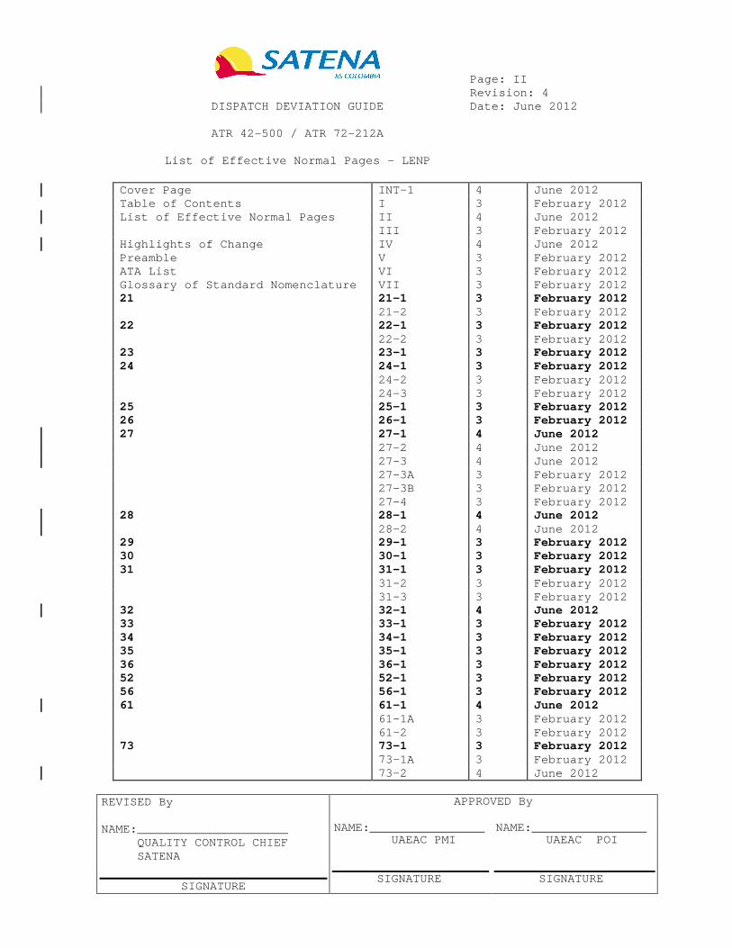
Page: II Revision: 4 DISPATCH DEVIATION GUIDE Date: June 2012 ATR 42-500 / ATR 72-212A List of Effective Normal Pages – LENP
Cover Page INT-1 4 June 2012 Table of Contents I 3 February 2012 List of Effective Normal Pages II 4 June 2012 III 3 February 2012 Highlights of Change IV 4 June 2012 Preamble V 3 February 2012 ATA List VI 3 February 2012 Glossary of Standard Nomenclature VII 3 February 2012 21 21-1 3 February 2012 21-2 3 February 2012 22 22-1 3 February 2012 22-2 3 February 2012 23 23-1 3 February 2012 24 24-1 3 February 2012 24-2 3 February 2012 24-3 3 February 2012 25 25-1 3 February 2012 26 26-1 3 February 2012 27 27-1 4 June 2012 27-2 4 June 2012 27-3 4 June 2012 27-3A 3 February 2012 27-3B 3 February 2012 27-4 3 February 2012 28 28-1 4 June 2012 28-2 4 June 2012 29 29-1 3 February 2012 30 30-1 3 February 2012 31 31-1 3 February 2012 31-2 3 February 2012 31-3 3 February 2012 32 32-1 4 June 2012 33 33-1 3 February 2012 34 34-1 3 February 2012 35 35-1 3 February 2012 36 36-1 3 February 2012 52 52-1 3 February 2012 56 56-1 3 February 2012 61 61-1 4 June 2012 61-1A 3 February 2012 61-2 3 February 2012 73 73-1 3 February 2012 73-1A 3 February 2012 73-2 4 June 2012
REVISED By NAME:_____________________ QUALITY CONTROL CHIEF SATENA
SIGNATURE
APPROVED By NAME:________________ UAEAC PMI SIGNATURE
NAME:________________ UAEAC POI SIGNATURE

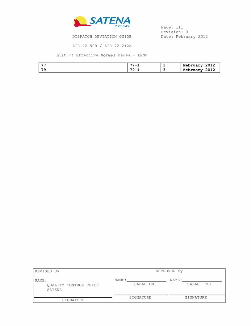
Page: III Revision: 3 DISPATCH DEVIATION GUIDE Date: February 2012 ATR 42-500 / ATR 72-212A List of Effective Normal Pages – LENP
77 77-1 3 February 2012 79 79-1 3 February 2012
REVISED By NAME:_____________________ QUALITY CONTROL CHIEF SATENA
SIGNATURE
APPROVED By NAME:________________ UAEAC PMI SIGNATURE
NAME:________________ UAEAC POI SIGNATURE

Page: IV Revision: 4 DISPATCH DEVIATION GUIDE Date: June 2012 ATR 42-500 / ATR 72-212A Highlights of Change
REV DATE DESCRIPTION 0 August 2010 ORIGINAL ALL PAGES 1 July 2011 ALL PAGES REVISED 2 November 2011 MSN 513 INCLUDED 3 February 2012 MSN’s 532 AND 521 INCLUDED 4 June 2012 MSN’s 571 AND 552 INCLUDED


Page: V Revision: 3 DISPATCH DEVIATION GUIDE Date: February 2012 ATR 42-500 / ATR 72-212A Preamble
Refer to ATR MEL Preamble.


Page: VI Revision: 3 DISPATCH DEVIATION GUIDE Date: February 2012 ATR 42-500 / ATR 72-212A ATA List
Refer to ATR MEL ATA List.


Page: VII Revision: 3 DISPATCH DEVIATION GUIDE Date: February 2012 ATR 42-500 / ATR 72-212A Glossary of Standard Nomenclature
Refer to ATR MEL Glossary of Standard Nomenclature.

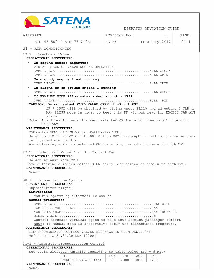
DISPATCH DEVIATION GUIDE
AIRCRAFT: REVISION NO : 3 PAGE:
ATR 42-500 / ATR 72-212A DATE: February 2012 21-1
21 – AIR CONDITIONING
23-1 – Overboard Valve OPERATIONAL PROCEDURES • On ground before departure
VISUAL CHECK OF VALVE NORMAL OPERATION: OVBD VALVE......................................... ....FULL CLOSE OVBD VALVE......................................... ....FULL OPEN
• On ground, engine 1 not running OVBD VALVE......................................... ....FULL OPEN
• In flight or on ground engine 1 running OVBD VALVE......................................... ....FULL CLOSE
• If EXHAUST MODE illuminates amber and ∆P ≤ 1PSI OVBD VALVE......................................... ....FULL OPEN
CAUTION: Do not select OVBD VALVE OPEN if ∆P > 1 PSI. ∆P ≤ 1PSI will be obtained by flying under FL115 and ad justing Z CAB in MAN PRESS mode in order to keep this DP without rea ching EXCESS CAB ALT alarm
Note: Avoid leaving avionics vent selected ON for a long period of time with high OAT
MAINTENANCE PROCEDURES OVERBOARD VENTILATION VALVE DE-ENERGIZATION: Refer to JIC 21-23-22 CHK 10000: 001 to 002 paragra ph 3, setting the valve open in intermediate position. Avoid leaving avionics selected ON for a long perio d of time with high OAT
23-2 - Underfloor Valve / 23-3 – Extract Fan
OPERATIONAL PROCEDURES Select exhaust mode OVBD. Avoid leaving avionics selected ON for a long perio d of time with high OAT.
MAINTENANCE PROCEDURES None.
30-1 - Pressurization System OPERATIONAL PROCEDURES
Unpressurized flight: Limitations
Maximum operating altitude: 10 000 ft Normal procedures
OVBD VALVE......................................... .....FULL OPEN CAB PRESS MODE SEL................................. .....MAN MAN RATE KNOB...................................... .....MAX INCREASE BLEED VALVE........................................ .....ON Control aircraft vertical speed to take into accoun t passenger comfort. Note: If manual mode is inoperative apply the maint enance procedure.
MAINTENANCE PROCEDURES ELECTROPNEUMATIC OUTFLOW VALVES BLOCKAGE IN OPEN POSITION: Refer to JIC 21.31.20 DNZ 10000.
31–1 - Automatic Pressurization Control OPERATIONAL PROCEDURES
Set cabin altitude manually according to table belo w ( ∆P = 6 PSI) L 140 170 200 250 TARGET CAB ALT (ft) 0 2000 4000 6750
MAINTENANCE PROCEDURES None.


DISPATCH DEVIATION GUIDE
AIRCRAFT: REVISION NO : 3 PAGE:
ATR 42-500 / ATR 72-212A DATE: February 2012 21-2
21 – AIR CONDITIONING
31-3 - Electropneumatic Outflow Valve OPERATIONAL PROCEDURES
None. MAINTENANCE PROCEDURES
ELECTROPNEUMATIC OUTFLOW VALVE DEACTIVATION: Refer to JIC 21.31.22 DNZ 10000.
31-4 - CABIN PRESS Indicator
OPERATIONAL PROCEDURES (1) Check ∆P according to table below:
FL 140 170 200 250 TARGET (PSI) 3.5 4.6 5.7 6.35
(2) and (3) Check cabin altitude according to table bel ow ( ∆P = 6 PSI):
FL 140 170 200 250 TARGET CAB ALT (ft) 0 2000 4000 6750
MAINTENANCE PROCEDURES
None.
35-1 - DUMP Function OPERATIONAL PROCEDURES
In case rapid depressurization of the aircraft is n eeded: MAN RATE KNOB...................................... ........MAN CAB PRESS MODE SEL................................. ........MAN MAN RATE KNOB...................................... ........MAX INCREASE Note: Residual ∆P may be cancelled using the cockpit communication door
MAINTENANCE PROCEDURES None.
50-1 - Pack / 51-1 - Pack Valve / 51-2 - Pack FAULT Alert
OPERATIONAL PROCEDURES As an in-flight failure could imply total loss of p ressurization, fuel consumption at FL100 must be taken into account to compute the trip fuel.
MAINTENANCE PROCEDURES Refer to JIC 21.11.51 DNZ 10000.
61-1 - Pack AUTO Temperature Control
OPERATIONAL PROCEDURES Adjust manually the pack discharge temperature to o btain the same duct indication as the other pack. If pack is not used, an in-flight failure could imp ly total loss of pressurization, so fuel consumption at FL100 must b e taken into account to compute the trip fuel.
MAINTENANCE PROCEDURES None.
61-3 - OVHT Alert
OPERATIONAL PROCEDURES Monitor and maintain DUCT indication below 92°C/200 °F.
MAINTENANCE PROCEDURES None.

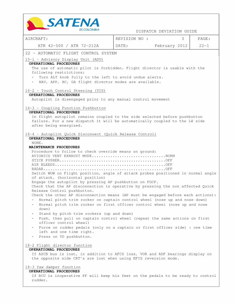
DISPATCH DEVIATION GUIDE
AIRCRAFT: REVISION NO : 3 PAGE:
ATR 42-500 / ATR 72-212A DATE: February 2012 22-1
22 – AUTOMATIC FLIGHT CONTROL SYSTEM
15-1 - Advisory Display Unit (ADU) OPERATIONAL PROCEDURES
The use of automatic pilot is forbidden. Flight dir ector is usable with the following restrictions: - Turn ALT knob fully to the left to avoid undue aler ts. - NAV, APP, BC, GA flight director modes are availabl e.
16-2 – Touch Control Steering (TCS)
OPERATIONAL PROCEDURES Autopilot is disengaged prior to any manual control movement
16-3 - Coupling Function Pushbutton
OPERATIONAL PROCEDURES In flight autopilot remains coupled to the side sel ected before pushbutton failure. For a new dispatch it will be automaticall y coupled to the LH side after being energized.
16-4 – Autopilot Quick Disconnect (Quick Release Co ntrol)
OPERATIONAL PROCEDURES NONE.
MAINTENANCE PROCEDURES Procedure to follow to check override means on grou nd: AVIONICS VENT EXHAUST MODE......................... .......NORM STICK PUSHER....................................... .......OFF AIR BLEEDS......................................... .......OFF RADAR.............................................. .......OFF Switch WOW on Flight position, angle of attack prob es positioned in normal angle of attack. (horizontal position) Engage the autopilot by pressing AP pushbutton on F GCP. Check that the AP disconnection is operative by pre ssing the non affected Quick Release Control pushbutton. Check the other AP disconnection means (AP must be engaged before each actions): - Normal pitch trim rocker on captain control wheel ( nose up and nose down) - Normal pitch trim rocker on first officer control w heel (nose up and nose
down) - Stand by pitch trim rockers (up and down) - Push, then pull on captain control wheel (repeat th e same actions on first
officer control wheel) - Force on rudder pedals (only on a captain or first officer side) : one time
left and one time right. - Press on YD pushbutton.
18-2 Flight director function
OPERATIONAL PROCEDURES If ASCB bus is lost, in addition to AFCS loss, VOR and ADF bearings display on the opposite side CRT’s are lost when using EFIS re version mode.
18-3 Yaw damper function OPERATIONAL PROCEDURES
If RCU is inoperative PF will keep his feet on the pedals to be ready to control rudder.

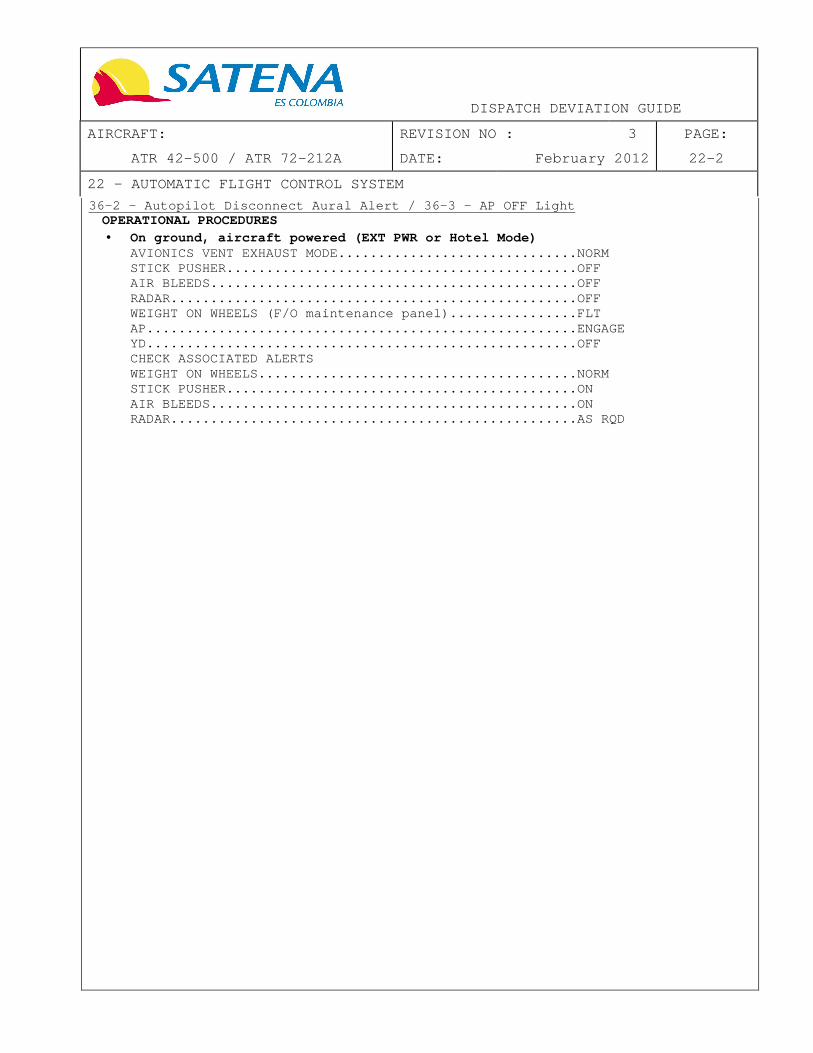
DISPATCH DEVIATION GUIDE
AIRCRAFT: REVISION NO : 3 PAGE:
ATR 42-500 / ATR 72-212A DATE: February 2012 22-2
22 – AUTOMATIC FLIGHT CONTROL SYSTEM
36-2 - Autopilot Disconnect Aural Alert / 36-3 - AP OFF Light OPERATIONAL PROCEDURES • On ground, aircraft powered (EXT PWR or Hotel Mode)
AVIONICS VENT EXHAUST MODE......................... .....NORM STICK PUSHER....................................... .....OFF AIR BLEEDS......................................... .....OFF RADAR.............................................. .....OFF WEIGHT ON WHEELS (F/O maintenance panel)........... .....FLT AP................................................. .....ENGAGE YD................................................. .....OFF CHECK ASSOCIATED ALERTS WEIGHT ON WHEELS................................... .....NORM STICK PUSHER....................................... .....ON AIR BLEEDS......................................... .....ON RADAR.............................................. .....AS RQD

DISPATCH DEVIATION GUIDE
AIRCRAFT: REVISION NO : 3 PAGE:
ATR 42-500 / ATR 72-212A DATE: February 2012 23-1
23 – COMMUNICATION
12-1 - VHF System OPERATIONAL PROCEDURES
To be defined by operator: operator must establish and use alternate normal, following failure and emergency procedures and/or o perating restrictions.
MAINTENANCE PROCEDURES None.
31-1 - Passenger Address System / 44-1 – Interphone System OPERATIONAL PROCEDURES
To be defined by operator: operator must establish and use alternate normal, following failure and emergency procedures and/or o perating restrictions.
MAINTENANCE PROCEDURES None.
44-2 Cabin Chime System OPERATIONAL PROCEDURES
When necessary flight crew must directly inform the cabin crew member that SIGNS are ON.
MAINTENANCE PROCEDURES None.
70-1 – Cockpit Video Surveillance System OPERATIONAL PROCEDURES
To be defined by operator: operator must establish and use alternate procedures and/or operating restrictions to identify persons r equesting entry to the flight crew compartment and to detect suspicious behavior or potential threat.
MAINTENANCE PROCEDURES
None.

DISPATCH DEVIATION GUIDE
AIRCRAFT: REVISION NO : 3 PAGE:
ATR 42-500 / ATR 72-212A DATE: February 2012 24-1
24 – ELECTRICAL POWER
21-2 - INV FAULT Alert OPERATIONAL PROCEDURES
After engines start select BTC ISOL. Check no amber light or flag on instruments come on.
MAINTENANCE PROCEDURES None.
22-1 - ACW Generator Channel (Generator + Related G CU) OPERATIONAL PROCEDURES
If accelerate stop has to be performed, EMER BRAKIN G has to be used. Refer to AFM Supplement N°017_02.01: Dispatch with one ACW generator channel inoperative.
MAINTENANCE PROCEDURES This procedure has to be performed prior to the nex t flight following the ACW generator channels fault triggering to detect a mec hanical damage (bearing failure...). Perform a visual inspection of the failed alternato r: � Look for overheating and/or presence of debris/chip s in the alternator-
cooling outlet. � Check for unusual noise from the alternator by manu ally rotating the
propeller. � If check satisfactory: repeat this inspection on a daily basis until the ACW
generator failure is repaired. � If check not satisfactory: replace the failed ACW g enerator prior to flight.
22-3 - ACW Generation Bus Tie Contactor
OPERATIONAL PROCEDURES � Open hydraulic X FEED before take off � Close it after flaps retraction � Open it in approach � Close it after landing Note: Two-engine taxi is recommended.
MAINTENANCE PROCEDURES None.
30-1 - DC Generator Channel (Generator + Related GC U) OPERATIONAL PROCEDURES � Check of remaining generator feeder integrity :
6 minutes are necessary to establish the temperatur e difference between the feeders if one line is broken. So aircraft should n ot line up until 6 minutes elapsed after operative generator comes on line.
� Operational test of TRU: Note: During the test, the ACW electrical network m ust be available (The AC GPU connected or ACW generators running) Checking are performed only on Main Electrical Pane l (left hand panel) - Switch OFF the pushbutton DC EXTERNAL POWER (if sel ected ON) - Switch OFF the pushbuttons DC GEN 1 & 2 (if selecte d ON).


DISPATCH DEVIATION GUIDE
AIRCRAFT: REVISION NO : 3 PAGE:
ATR 42-500 / ATR 72-212A DATE: February 2012 24-2
24 – ELECTRICAL POWER
30-1 - DC Generator Channel (Generator + Related GC U) (Cont’d) On Main Electrical Panel; check that the following caution lights are switched ON: - -BATTERY ARROWS, - Both BUS OFF, - INVERTER 2 FAULT, - Both DC BUS OFF, - SHED LEGEND OF DC SVCE/UTLY BUS Check that the following systems are supplied: - VHF 1, - FUEL QTY INDICATOR, - FLAPS POSITION INDICATOR On Main Electrical Panel; press the TRU push-button ; then check that: - The TRU push-button is switched ON, - The TRU ARROW caution light is switched ON, - The BATTERIES ARROWS caution lights are not illumin ated, - The UNDV legend of OVRD/UNDV push-button is not ill uminated. On Main Electrical Panel, check that the BATTERY AM METER shows zero load either if BAT selector switch is placed in EMER or MAIN position. Check that the following systems are still supplied : - VHF 1, - FUEL QTY INDICATOR, - FLAPS POSITION INDICATOR. On Main Electrical Panel, switch off the TRU push-b utton; then check that: - The TRU push-button is not illuminated, - The TRU ARROW caution light is not illuminated, - The BATTERY ARROWS caution lights are switched ON.
MAINTENANCE PROCEDURES Operational test of TRU: refer to JIC 24.31.81 OPT 10000.
30-2 - Transformer Rectifier Unit (TRU)
OPERATIONAL PROCEDURES In case of DUAL DC GEN LOSS the following procedure has to be applied:
DC GEN 1 AND 2..................................... .........OFF THEN ON � If no generator recovered
LAND ASAP, flight under IMC must be limited to 30 m inutes BAT SW............................................. .....OVRD Note: If after a restart, a DC GEN becomes operativ e, set BAT SW to ON. CAPT EHSI.......................................... .....OFF MAN RATE KNOB...................................... .....9 O'CLOCK CAB PRESS MODE SEL................................. .....MAN ATC (VHF 1 or HF or HF 2).......................... .....NOTIFY MIN CAB LT......................................... .....OFF Note: NAV lights switch set to ON is necessary to p rovide IEP illumination. STICK PUSHER / SHAKER.............................. .....OFF STICK PUSHER / SHAKER FAULT procedure.............. .....APPLY SIDE WINDOWS ANTI-ICING............................ .....OFF AVIONICS VENT EXHAUST MODE......................... .....OVBD ADC SW............................................. .....SET TO ADC 1 ATC SW............................................. .....SET TO ATC 1 TLU................................................ .....MAN MODE LO SPD

DISPATCH DEVIATION GUIDE
AIRCRAFT: REVISION NO : 3 PAGE:
ATR 42-500 / ATR 72-212A DATE: February 2012 24-3
24 – ELECTRICAL POWER
30-2 – Transformer Rectifier Unit (TRU) (Cont’d) � When TLU LO SPD illuminates
TLU................................................ .....AUTO CAUTION: Avoid large rudder input if IAS above 180 kt MAIN BATTERY CHARGE (on LH maintenance panel)...... .....CHECK BUS EQUIPMENT LISTS................................ .....CHECK
� If STBY UNDV light illuminates STBY BUS...............................For approach , OVRD only when necessary
� Before descent PAX INSTRUCTIONS................................... .....USE PASSENGER ADDRESS
� At touch down IDLE GATE LEVER.................................... .....PULL
MAINTENANCE PROCEDURES None.
32-2 - DC generation Bus Tie Contactor
OPERATIONAL PROCEDURES Note: Two-engine taxi is recommended. CAUTION: While aircraft is on ground, if LH DC gene rator fails, then automatic pressurization digital controller supplied by DC BU S 1 is lost. Therefore, both outflow valves will close and aircraft will be pres surized. In this case, use manual pressurization to depressurize the aircraft.
MAINTENANCE PROCEDURES None.


DISPATCH DEVIATION GUIDE
AIRCRAFT: REVISION NO : 3 PAGE:
ATR 42-500 / ATR 72-212A DATE: February 2012 25-1
25 – EQUIPMENT/FURNISHINGS
21-1 - Required Cabin Attendant Seat / 21-2 Non-Req uired Cabin Attendant Seat OPERATIONAL PROCEDURES
To be defined by operator: operator must establish and use alternate normal, following failure and emergency procedures and/or o perating restrictions.
MAINTENANCE PROCEDURES To be defined by operator to follow corresponding M EL 25 conditions.
31-1 - Passenger Seats
OPERATIONAL PROCEDURES None.
MAINTENANCE PROCEDURES To be defined by operator to follow corresponding M EL 25 conditions.
45-1 - Portable Protective Breathing Equipment
OPERATIONAL PROCEDURES None.
MAINTENANCE PROCEDURES To be defined by operator to follow corresponding M EL 25 conditions.
80-1 Separation Door and Sliding Panels of the Part ition
OPERATIONAL PROCEDURES None.
MAINTENANCE PROCEDURES In case of malfunction, separation door and/or slid ing panels may be secured blocked in open position or removed. Refer to JIC 2 5-26-25 RAI 10000.


DISPATCH DEVIATION GUIDE
AIRCRAFT: REVISION NO : 3 PAGE:
ATR 42-500 / ATR 72-212A DATE: February 2012 26-1
26 – FIRE PROTECTION
21-1 - AGENT DISCH Light OPERATIONAL PROCEDURES
None. MAINTENANCE PROCEDURES
Refer to JIC 26.21.00 CHK 10000.
30-1 - Hand Fire Extinguisher OPERATIONAL PROCEDURES
None. MAINTENANCE PROCEDURES
To be defined by operator to follow corresponding M EL 26 conditions.

DISPATCH DEVIATION GUIDE
AIRCRAFT: REVISION NO : 4 PAGE:
ATR 42-500 / ATR 72-212A DATE: June 2012 27-1
27 – FLIGHT CONTROLS
20-1 - Rudder Damper OPERATIONAL PROCEDURES
Pilot Flying and Pilot Non Flying must keep their f eet on the pedals during all the taxi phases in order to avoid rudder excessive movements. Pilot Flying will avoid large pedal movements during take off run and landing and will prefer nose wheel steering use.
MAINTENANCE PROCEDURES None.
20-2 - Rudder Releasable Control Unit
OPERATIONAL PROCEDURES If the yaw damper is inoperative, Pilot Flying will keep his feet on the pedals to be ready to control rudder.
MAINTENANCE PROCEDURES None.
23-1 - Travel Limiter Unit (TLU)
OPERATIONAL PROCEDURES During Cockpit preparation:
• Select manually HI SPD and check alert is generated after 25 seconds: master caution, single chime, FLT CTL on CAP and TLU FAULT light. Check rudder travel limited.
• Select LO SPD and check alert stops after 15 second s and check rudder travel no longer limited.
In flight select manually: For ATR 42: � HI SPD when reaching 195 kt during an acceleration. � LO SPD when reaching 190 kt during a deceleration. For ATR 72: � HI SPD when reaching 185 kt during an acceleration. � LO SPD when reaching 180 kt during a deceleration.
MAINTENANCE PROCEDURES None.
23-2 - TLU FAULT Light
OPERATIONAL PROCEDURES During Cockpit preparation:
• Select manually HI SPD and check alert is generated after 25 seconds: master caution, single chime, FLT CTL on CAP. Check rudder travel limited.
• Select LO SPD and check alert stops after 15 second s and check rudder travel no longer limited.
In flight select manually: For ATR 42: � HI SPD when reaching 195 kt during an acceleration. � LO SPD when reaching 190 kt during a deceleration. For ATR 72: � HI SPD when reaching 185 kt during an acceleration. � LO SPD when reaching 180 kt during a deceleration.
MAINTENANCE PROCEDURES None.

DISPATCH DEVIATION GUIDE
AIRCRAFT: REVISION NO : 4 PAGE:
ATR 42-500 / ATR 72-212A DATE: June 2012 27-2
27 – FLIGHT CONTROLS
35-1 - Pitch Trim Position Indicator OPERATIONAL PROCEDURES
During TAXI check list run the trim from nose up to nose down: from the trim position where the whooler stops, run the trim from nose down to nose up for 13 seconds.
MAINTENANCE PROCEDURES None.
36-2 - Stick Pusher Actuator
OPERATIONAL PROCEDURES Select stick pusher/shaker pushbutton ON. Check control wheel remains free of movement and st ick pusher/shaker fault light is extinguished. Note: If control column is stuck refer to maintenan ce procedure (disassembling of stick pusher). Pull C/B ”stick pusher PWR”. Perform stick shakers test using stick pusher/shake r YES.
MAINTENANCE PROCEDURES STICK PUSHER ACTUATOR REMOVAL: Refer to JIC 27.36.31 RAI 10000.
37-1 - Pitch Elevators Coupling System
OPERATIONAL PROCEDURES None.
MAINTENANCE PROCEDURES If "Pitch disconnect" warning light is illuminated steady: no maintenance action is required before Ferry Flight. If "Pitch disconnect" warning is blinking: deactiva te the elevator reconditioning device: Refer to JIC 27.31.43 DAR 10 005.
37-2 - Elevator Clutch Reconditioning Device
OPERATIONAL PROCEDURES None.
MAINTENANCE PROCEDURES Refer to JIC 27.31.43 DAR 10000.
51-1 - Flaps Control System
OPERATIONAL PROCEDURES Check flaps are in retracted position and flaps con trol lever is in zero position. Refer to AFM Supplement N°01 7_02.03: Dispatch with flaps retracted. Pitch trim setting for flaps 0 take off: see DDG 27 page 4.
MAINTENANCE PROCEDURES None.
55-1 - Flaps Position Indicator
OPERATIONAL PROCEDURES Check visually flaps position at each configuration change.
MAINTENANCE PROCEDURES None.

DISPATCH DEVIATION GUIDE
AIRCRAFT: REVISION NO : 4 PAGE:
ATR 42-500 / ATR 72-212A DATE: June 2012 27-3
27 – FLIGHT CONTROLS
61-1 - Spoiler Control System OPERATIONAL PROCEDURES
Refer to AFM Supplement N°01 7_02.02: Dispatch with spoilers control system inoperative.
MAINTENANCE PROCEDURES Refer to JIC 27.61.00 DAR 10000.
70-1 - GUST LOCK System
OPERATIONAL PROCEDURES Take special care for parking and taxi (wind effect s).
MAINTENANCE PROCEDURES 1) Aileron
Perform a daily inspection of Aileron hinge fitting stops (on RH and LH) 1. Install notice prohibiting operation of flight cont rols in flight
compartment. 2. Install access platform. 3. Remove fairing 555AB or 655AB according to aileron to be inspected.
Note: LH and RH wings aileron hinge fitting stops m ust be inspected. 4. Manually move the aileron until reaching the upper stop. 5. Perform a Detailed Visual Inspection of aileron cen ter fitting, aileron
control fitting and lower stop as per NDTM 51-90-00 . In case of findings, contact ATR prior any action.
6. Manually move the aileron until reaching the lower stop. 7. Perform a Detailed Visual Inspection of aileron cen ter fitting, aileron
control fitting and upper stop as per NDTM 51-90-00 . In case of findings, contact ATR prior any action.
8. Install fairing 555AB or 655AB. 9. Remove warning notices and access platform.
2) Elevator Perform a daily inspection of elevator hinge fittin g stops (on RH and LH)
1. Install notice prohibiting operation of flight cont rols in flight compartment.
2. Install access platform. 3. Remove access panels 333CB and 343CB. 4. Maintain elevators in full nose up position (traili ng edge upward). 5. Perform a Detailed Visual Inspection of elevators i nboard hinge fittings
and stops as per NDTM 51-90-00. In case of findings , contact ATR prior any action.
6. Install access panels 333CB and 343CB. 7. Remove warning notices and access platform.
Following items must be considered, in addition or replacing corresponding items on this page.

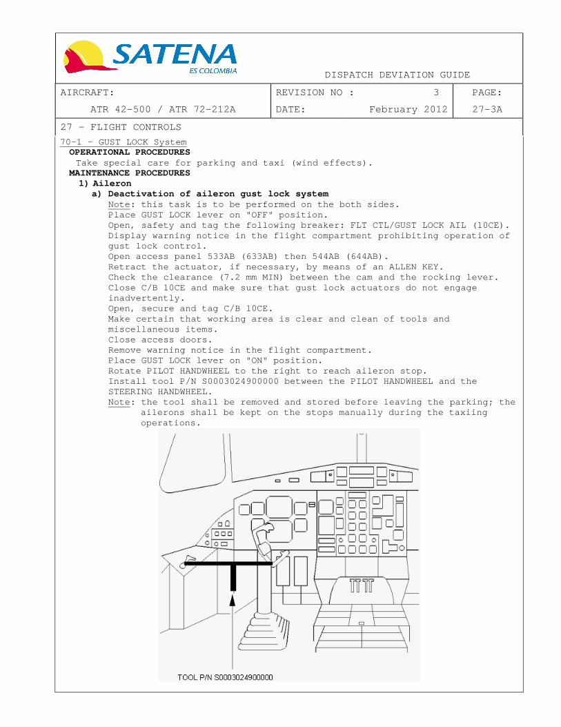
DISPATCH DEVIATION GUIDE
AIRCRAFT: REVISION NO : 3 PAGE:
ATR 42-500 / ATR 72-212A DATE: February 2012 27-3A
27 – FLIGHT CONTROLS
70-1 - GUST LOCK System OPERATIONAL PROCEDURES
Take special care for parking and taxi (wind effect s). MAINTENANCE PROCEDURES
1) Aileron a) Deactivation of aileron gust lock system
Note: this task is to be performed on the both side s. Place GUST LOCK lever on "OFF" position. Open, safety and tag the following breaker: FLT CTL /GUST LOCK AIL (10CE). Display warning notice in the flight compartment pr ohibiting operation of gust lock control. Open access panel 533AB (633AB) then 544AB (644AB). Retract the actuator, if necessary, by means of an ALLEN KEY. Check the clearance (7.2 mm MIN) between the cam an d the rocking lever. Close C/B 10CE and make sure that gust lock actuato rs do not engage inadvertently. Open, secure and tag C/B 10CE. Make certain that working area is clear and clean o f tools and miscellaneous items. Close access doors. Remove warning notice in the flight compartment. Place GUST LOCK lever on "ON" position. Rotate PILOT HANDWHEEL to the right to reach ailero n stop. Install tool P/N S0003024900000 between the PILOT H ANDWHEEL and the STEERING HANDWHEEL. Note: the tool shall be removed and stored before l eaving the parking; the
ailerons shall be kept on the stops manually during the taxiing operations.

DISPATCH DEVIATION GUIDE
AIRCRAFT: REVISION NO : 3 PAGE:
ATR 42-500 / ATR 72-212A DATE: February 2012 27-3B
27 – FLIGHT CONTROLS
70-1 - GUST LOCK System (Cont’d) b) Perform a daily inspection of Aileron hinge fitting stops (on RH and LH)
1. Install notice prohibiting operation of flight cont rols in flight compartment.
2. Install access platform. 3. Remove fairing 555AB or 655AB according to aileron to be inspected.
Note: LH and RH wings aileron hinge fitting stops m ust be inspected. 4. Manually move the aileron until reaching the upper stop. 5. Perform a Detailed Visual Inspection of aileron cen ter fitting, aileron
control fitting and lower stop as per NDTM 51-90-00 . In case of findings, contact ATR prior any action.
6. Manually move the aileron until reaching the lower stop. 7. Perform a Detailed Visual Inspection of aileron cen ter fitting, aileron
control fitting and upper stop as per NDTM 51-90-00 . In case of findings, contact ATR prior any action.
8. Install fairing 555AB or 655AB. 9. Remove warning notices and access platform.
2) Elevator Perform a daily inspection of elevator hinge fittin g stops (on RH and LH) 1. Install notice prohibiting operation of flight cont rols in flight
compartment. 2. Install access platform. 3. Remove access panels 333CB and 343CB. 4. Maintain elevators in full nose up position (traili ng edge upward). 5. Perform a Detailed Visual Inspection of elevators i nboard hinge
fittings and stops as per NDTM 51-90-00. In case of findings, contact ATR prior any action.
6. Install access panels 333CB and 343CB. 7. Remove warning notices and access platform.

DISPATCH DEVIATION GUIDE
AIRCRAFT: REVISION NO : 3 PAGE:
ATR 42-500 / ATR 72-212A DATE: February 2012 27-4
27 – FLIGHT CONTROLS
51-1 - Flaps Control System (Cont’d) OPERATIONAL PROCEDURES
Pitch trim setting for flaps 0 take off Refer to AFM 7.02.03


DISPATCH DEVIATION GUIDE
AIRCRAFT: REVISION NO : 4 PAGE:
ATR 42-500 / ATR 72-212A DATE: June 2012 28-1
28 – FUEL
21-1 - FEED LO PR Light OPERATIONAL PROCEDURES
Cockpit preparation: CL................................................. ........FTR Note: For ATR 42-300/320, CL may be set slightly ab ove FTR. RH and LH PUMPS.................................... ........CHECK ON FUEL light on CAP.................................. ........CHECK EXTINGUISHED LH PUMP............................................ ........SELECT OFF MC light + SC + FUEL light on CAP.................. ........CHECK LH PUMP............................................ ........SELECT ON Associated alerts.................................. ........CHECK EXTINGUISH RH PUMP............................................ ........SELECT OFF Associated alerts.................................. ........CHECK ILLUMINATE RH PUMP............................................ ........SELECT ON Associated alerts.................................. ........CHECK EXTINGUISH
MAINTENANCE PROCEDURES None.
21-2 - Electrical Pump
OPERATIONAL PROCEDURES Alternate route study must be performed taking into account the non-affected side tank value only. Maximum fuel unbalance is limited to : ATR 42 : 550 kg (1212 lbs) ATR 72 : 730 kg (1609 lbs) Cockpit preparation:
X FEED............................................. ...CHECK X LINE INOPERATIVE PUMP................................... ...OFF OPERATIVE PUMP..................................... ...ON ENG FEED LO PR on operative side................... ...CHECK EXTINGUISHED ENG FEED LO PR on inoperative side................. ...CHECK REMAINS ILLUMINATED X FEED............................................. ...IN LINE ENG FEED LO PR on inoperative side................. ...CHECK EXTINGUISHED X FEED............................................. ...X LINE OPERATIVE PUMP..................................... ...OFF ENG FEED LO PR on both sides....................... ...CHECK ILLUMINATED OPERATIVE PUMP..................................... ...AS RQD
• Before affected engine start X FEED............................................. ...IN LINE
• After affected engine start INOPERATIVE PUMP................................... ...ON Note: This allows motive flow valve and then jet pu mp to be operative X FEED............................................. ..X LINE ENG FEED LO PR lights.............................. ..CHECK REMAINS EXTINGUISHED
MAINTENANCE PROCEDURES Associated breaker 1QA or 2QA to be pulled out and tagged.


DISPATCH DEVIATION GUIDE
AIRCRAFT: REVISION NO : 4 PAGE:
ATR 42-500 / ATR 72-212A DATE: June 2012 28-2
28 – FUEL
23-1 - X FEED Valve OPERATIONAL PROCEDURES
Dispatch without any asymmetry. Maximum fuel unbalance is limited to: ATR 42 : 550 kg (1212 lbs) ATR 72 : 730 kg (1609 lbs) Alternate route study must be performed taking into account the lowest tank value only. When selecting RH PUMP ON check ENG 2 FEED LO PR li ght extinguishes and ENG 1 FEED LO PR light remains illuminated.
MAINTENANCE PROCEDURES None.
23-2 - X FEED Flow Bar
OPERATIONAL PROCEDURES When selecting RH PUMP ON check ENG 2 FEED LO PR li ght extinguishes and ENG 1 FEED LO PR light remains illuminated.
MAINTENANCE PROCEDURES None.
25-1 - Refueling Panel
OPERATIONAL PROCEDURES None.
MAINTENANCE PROCEDURES Refer to JIC 12-1100 FLG 10025 for manual refueling .
25-2 - Pressure Refueling Cap
OPERATIONAL PROCEDURES None.
MAINTENANCE PROCEDURES To be defined by operator to follow corresponding M EL 28 conditions.
41-1 – Tank Temperature Indication
OPERATIONAL PROCEDURES Note: Refer to AFM 2.04.05 for temperature limitati on.
Maintenance procedures None.
42-1 Fuel QTY indication
OPERATIONAL PROCEDURES In case of suspected fuel leak or fuel unbalance (a n excessive aileron trim indication may help for detection), maintain X FEED valve CLOSED. See FCOM 2.06.
Maintenance procedures Refer to JIC 12-1100 FLG 10025 for manual refueling . Refer to JIC 28-42-72 FUT 10020 (FUNCTIONAL TEST OF FEEDER TANK LOW LEVEL SENSOR)

DISPATCH DEVIATION GUIDE
AIRCRAFT: REVISION NO : 3 PAGE:
ATR 42-500 / ATR 72-212A DATE: February 2012 29-1
29 – HYDRAULIC SYSTEM
11-1 - Main HYD Pump OPERATIONAL PROCEDURES
Two-engine taxi is recommended. MAINTENANCE PROCEDURES
Refer to JIC 290000 CHK 10000 to check the level of hydraulic fluid. 31-1 - LO LVL Alert / 32-1 - LO PR Alert
OPERATIONAL PROCEDURES Monitor associated HYD SYS pressure indication thro ughout the flight.
MAINTENANCE PROCEDURES None.
33-1 – Main Hydraulic Pump OVHT Alert OPERATIONAL PROCEDURES
During the cockpit preparation, the associated main hydraulic pump is set to OFF MAINTENANCE PROCEDURES
None.
33-2 – DC AUX Pump OVHT Alert OPERATIONAL PROCEDURES
The DC AUX pump is set to OFF. MAINTENANCE PROCEDURES
None.

DISPATCH DEVIATION GUIDE
AIRCRAFT: REVISION NO : 3 PAGE:
ATR 42-500 / ATR 72-212A DATE: February 2012 30-1
30 – ICE AND RAIN PROTECTION
MAINTENANCE PROCEDURES None for this chapter.
11-1 - De-ice Pressure Regulating and Shut Off Valv e
OPERATIONAL PROCEDURES � If both de-ice valves are in closed position
CL should be manually set on MAX RPM before landing 11-4 - AFR AIR BLEED FAULT Alert
OPERATIONAL PROCEDURES With bleed supply: AFR AIR BLEED...................................... .......ON DE-ICING AIR FRAME................................. .......ON AIRFRAME FAULT light............................... .......CHECK EXTINGUISHES AFR AIR BLEED...................................... .......OFF AIRFRAME FAULT light............................... .......CHECK ILLUMINATES
31-1 - TAT
OPERATIONAL PROCEDURES Select ADC associated to valid TAT probe. TAT heating loss may affect FDAU Torque computation . Crosscheck with tables.
31-3 - Alert
OPERATIONAL PROCEDURES Check by hand the correct functioning of the heatin g system.
60-4 - WINDSHIELD HTG FAULT Light
OPERATIONAL PROCEDURES Check by hand the correct functioning of the respec tive heating system.
61-2 - Propeller Anti-icing ON Light
OPERATIONAL PROCEDURES While engines are running with CL to MAX RPM / AUTO (depending on version) : ACW generation..................................... .......OFF PROP ANTI-ICING affected........................... .......ON FAULT alert........................................ .......CHECK GENERATED

DISPATCH DEVIATION GUIDE
AIRCRAFT: REVISION NO : 3 PAGE:
ATR 42-500 / ATR 72-212A DATE: February 2012 31-1
31 – INSTRUMENTS
Maintenance procedures None in Chapter 31.
31-1 - MPC: APM
OPERATIONAL PROCEDURES Airplane Performance Monitoring (APM) Monitor the ICING CONDITIONS and SPEED as requested in Airplane Flight Manual Appendix 7.01.15 in Normal, Following Failures and Abnormal procedures for flight in normal and severe icing conditions.
48–1–1 - MFC Module 1A
OPERATIONAL PROCEDURES • During cockpit preparation
� FWD COMPT door must be visually checked locked clos ed prior to each departure.
� FWD cargo door must be manually activated. � DESELECT DC SVCE/UTLY BUS in case of LH single DC G EN operation on ground. � PULL C/B INV 2 and check AC STBY BUS is supplied. Note: CAPT ADC connected instruments operate normal ly – F/O ADC instruments are lost. � PUSH IN C/B INV 2. Following warnings have to be tested prior to the f irst flight of the day: � Provide blue HYD PRESS. STICK PUSHER INHIBITION TEST � Select HORNS anti-icing ON then OFF. � Disengage GUST LOCK. � On LH maintenance panel, set ROTARY SELECTOR to STI CK PUSHER TEST 2. � Depress and maintain PTT. � On LH maintenance panel, CHECK CH 2 light is illumi nated. � Check RH stick shaker and stall warning are activat ed � Check STICK PUSHER/SHAKER FAULT light is illuminate d after 5 seconds. � Check STICK PUSHER is not activated after 10 second s. � Set ROTARY SELECTOR to NORM FLT. � Clear ICING AOA light. � GUST LOCK engaged. FLAPS UNLOCK TEST � SET FLAPS 15. � On RH maintenance panel, depress and maintain FLAPS UNLOCK PTT. � Check warning is activated when the flaps position passes over the
selected position minus 3° on the indicator. � SET FLAPS AS RQD.
• When one engine running � Select de icing OVRD mode and visually check boots inflation. � Select de icing OVRD mode to NORM position. Refer to module equipment list and note missing fun ctions.

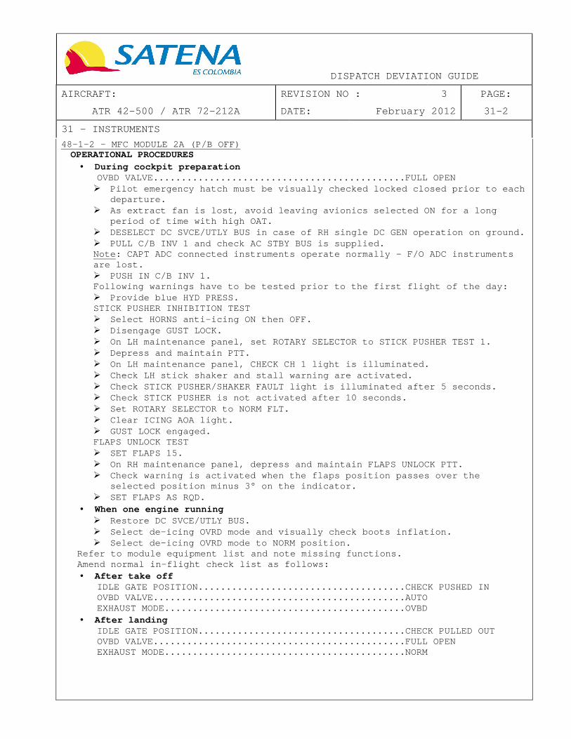
DISPATCH DEVIATION GUIDE
AIRCRAFT: REVISION NO : 3 PAGE:
ATR 42-500 / ATR 72-212A DATE: February 2012 31-2
31 – INSTRUMENTS
48–1–2 - MFC MODULE 2A (P/B OFF) OPERATIONAL PROCEDURES
• During cockpit preparation OVBD VALVE......................................... ....FULL OPEN � Pilot emergency hatch must be visually checked lock ed closed prior to each
departure. � As extract fan is lost, avoid leaving avionics sele cted ON for a long
period of time with high OAT. � DESELECT DC SVCE/UTLY BUS in case of RH single DC G EN operation on ground. � PULL C/B INV 1 and check AC STBY BUS is supplied. Note: CAPT ADC connected instruments operate normal ly – F/O ADC instruments are lost. � PUSH IN C/B INV 1. Following warnings have to be tested prior to the f irst flight of the day: � Provide blue HYD PRESS. STICK PUSHER INHIBITION TEST � Select HORNS anti-icing ON then OFF. � Disengage GUST LOCK. � On LH maintenance panel, set ROTARY SELECTOR to STI CK PUSHER TEST 1. � Depress and maintain PTT. � On LH maintenance panel, CHECK CH 1 light is illumi nated. � Check LH stick shaker and stall warning are activat ed. � Check STICK PUSHER/SHAKER FAULT light is illuminate d after 5 seconds. � Check STICK PUSHER is not activated after 10 second s. � Set ROTARY SELECTOR to NORM FLT. � Clear ICING AOA light. � GUST LOCK engaged. FLAPS UNLOCK TEST � SET FLAPS 15. � On RH maintenance panel, depress and maintain FLAPS UNLOCK PTT. � Check warning is activated when the flaps position passes over the
selected position minus 3° on the indicator. � SET FLAPS AS RQD.
• When one engine running � Restore DC SVCE/UTLY BUS. � Select de-icing OVRD mode and visually check boots inflation. � Select de-icing OVRD mode to NORM position.
Refer to module equipment list and note missing fun ctions. Amend normal in-flight check list as follows: • After take off
IDLE GATE POSITION................................. ....CHECK PUSHED IN OVBD VALVE......................................... ....AUTO EXHAUST MODE....................................... ....OVBD
• After landing IDLE GATE POSITION................................. ....CHECK PULLED OUT OVBD VALVE......................................... ....FULL OPEN EXHAUST MODE....................................... ....NORM

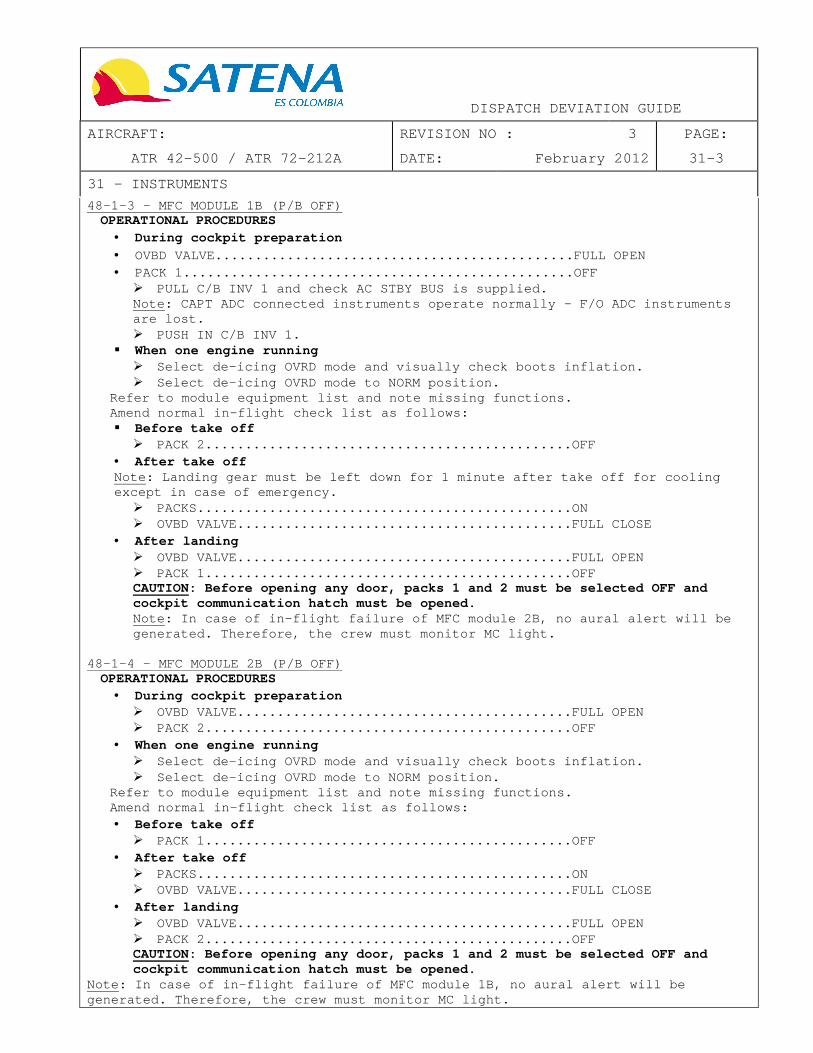
DISPATCH DEVIATION GUIDE
AIRCRAFT: REVISION NO : 3 PAGE:
ATR 42-500 / ATR 72-212A DATE: February 2012 31-3
31 – INSTRUMENTS
48-1-3 - MFC MODULE 1B (P/B OFF) OPERATIONAL PROCEDURES
• During cockpit preparation
• OVBD VALVE......................................... ....FULL OPEN • PACK 1............................................. ....OFF
� PULL C/B INV 1 and check AC STBY BUS is supplied. Note: CAPT ADC connected instruments operate normal ly – F/O ADC instruments are lost. � PUSH IN C/B INV 1.
� When one engine running � Select de-icing OVRD mode and visually check boots inflation. � Select de-icing OVRD mode to NORM position.
Refer to module equipment list and note missing fun ctions. Amend normal in-flight check list as follows: � Before take off
� PACK 2............................................. .OFF • After take off Note: Landing gear must be left down for 1 minute a fter take off for cooling except in case of emergency.
� PACKS.............................................. .ON � OVBD VALVE......................................... .FULL CLOSE
• After landing � OVBD VALVE......................................... .FULL OPEN � PACK 1............................................. .OFF CAUTION: Before opening any door, packs 1 and 2 mus t be selected OFF and cockpit communication hatch must be opened. Note: In case of in-flight failure of MFC module 2B , no aural alert will be generated. Therefore, the crew must monitor MC light.
48-1-4 - MFC MODULE 2B (P/B OFF)
OPERATIONAL PROCEDURES • During cockpit preparation
� OVBD VALVE......................................... .FULL OPEN � PACK 2............................................. .OFF
• When one engine running � Select de-icing OVRD mode and visually check boots inflation. � Select de-icing OVRD mode to NORM position.
Refer to module equipment list and note missing fun ctions. Amend normal in-flight check list as follows: • Before take off
� PACK 1............................................. .OFF • After take off
� PACKS.............................................. .ON � OVBD VALVE......................................... .FULL CLOSE
• After landing � OVBD VALVE......................................... .FULL OPEN � PACK 2............................................. .OFF CAUTION: Before opening any door, packs 1 and 2 mus t be selected OFF and cockpit communication hatch must be opened.
Note: In case of in-flight failure of MFC module 1B , no aural alert will be generated. Therefore, the crew must monitor MC ligh t.

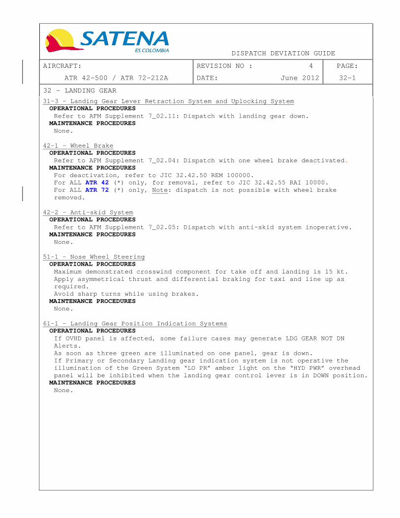
DISPATCH DEVIATION GUIDE
AIRCRAFT: REVISION NO : 4 PAGE:
ATR 42-500 / ATR 72-212A DATE: June 2012 32-1
32 – LANDING GEAR
31-3 - Landing Gear Lever Retraction System and Upl ocking System OPERATIONAL PROCEDURES
Refer to AFM Supplement 7_02.11: Dispatch with land ing gear down. MAINTENANCE PROCEDURES
None. 42-1 - Wheel Brake
OPERATIONAL PROCEDURES Refer to AFM Supplement 7_02.04: Dispatch with one wheel brake deactivated .
MAINTENANCE PROCEDURES For deactivation, refer to JIC 32.42.50 REM 100000. For ALL ATR 42 (*) only, for removal, refer to JIC 32.42.55 RAI 1 0000. For ALL ATR 72 (*) only, Note: dispatch is not possible with whee l brake removed.
42-2 - Anti-skid System
OPERATIONAL PROCEDURES Refer to AFM Supplement 7_02.05: Dispatch with anti -skid system inoperative.
MAINTENANCE PROCEDURES None.
51-1 - Nose Wheel Steering
OPERATIONAL PROCEDURES Maximum demonstrated crosswind component for take o ff and landing is 15 kt. Apply asymmetrical thrust and differential braking for taxi and line up as required. Avoid sharp turns while using brakes.
MAINTENANCE PROCEDURES None.
61-1 - Landing Gear Position Indication Systems
OPERATIONAL PROCEDURES If OVHD panel is affected, some failure cases may g enerate LDG GEAR NOT DN Alerts. As soon as three green are illuminated on one panel , gear is down. If Primary or Secondary Landing gear indication sys tem is not operative the illumination of the Green System “LO PR” amber ligh t on the “HYD PWR” overhead panel will be inhibited when the landing gear contr ol lever is in DOWN position.
MAINTENANCE PROCEDURES None.

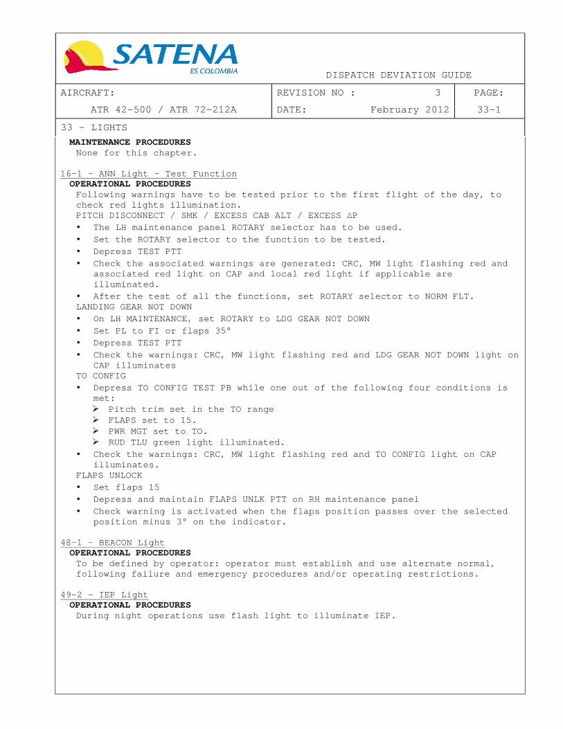
DISPATCH DEVIATION GUIDE
AIRCRAFT: REVISION NO : 3 PAGE:
ATR 42-500 / ATR 72-212A DATE: February 2012 33-1
33 – LIGHTS
MAINTENANCE PROCEDURES None for this chapter.
16-1 - ANN Light – Test Function OPERATIONAL PROCEDURES
Following warnings have to be tested prior to the f irst flight of the day, to check red lights illumination. PITCH DISCONNECT / SMK / EXCESS CAB ALT / EXCESS ∆P • The LH maintenance panel ROTARY selector has to be used. • Set the ROTARY selector to the function to be teste d. • Depress TEST PTT • Check the associated warnings are generated: CRC, M W light flashing red and
associated red light on CAP and local red light if applicable are illuminated.
• After the test of all the functions, set ROTARY sel ector to NORM FLT. LANDING GEAR NOT DOWN • On LH MAINTENANCE, set ROTARY to LDG GEAR NOT DOWN • Set PL to FI or flaps 35° • Depress TEST PTT • Check the warnings: CRC, MW light flashing red and LDG GEAR NOT DOWN light on
CAP illuminates TO CONFIG • Depress TO CONFIG TEST PB while one out of the foll owing four conditions is
met: � Pitch trim set in the TO range � FLAPS set to 15. � PWR MGT set to TO. � RUD TLU green light illuminated.
• Check the warnings: CRC, MW light flashing red and TO CONFIG light on CAP illuminates.
FLAPS UNLOCK • Set flaps 15 • Depress and maintain FLAPS UNLK PTT on RH maintenan ce panel • Check warning is activated when the flaps position passes over the selected
position minus 3° on the indicator. 48-1 - BEACON Light
OPERATIONAL PROCEDURES To be defined by operator: operator must establish and use alternate normal, following failure and emergency procedures and/or o perating restrictions.
49-2 - IEP Light
OPERATIONAL PROCEDURES During night operations use flash light to illumina te IEP.


DISPATCH DEVIATION GUIDE
AIRCRAFT: REVISION NO : 3 PAGE:
ATR 42-500 / ATR 72-212A DATE: February 2012 34-1
34 – NAVIGATION
MAINTENANCE PROCEDURES None for this chapter.
11-1 - ADC
OPERATIONAL PROCEDURES ADC switching must be set to valid ADC TLU manual mode check: � Select HI SPD and check alert is generated after 25 seconds: MC, SC, FLT CTL
on CAP and TLU FAULT light. � Check rudder travel is limited � Select AUTO and check alert stops after 15 seconds. � Check rudder travel is not limited
13-1-2 - Airspeed Indicator – Speed Selectors
OPERATIONAL PROCEDURES FAST/SLOW indication on the EADI is lost.
15-1 - Temperature Indication
OPERATIONAL PROCEDURES Aircraft must be considered as flying in icing cond itions as soon as visible moisture is encountered regardless of temperature. If anti-icing and/or de-icing systems need to be us ed, mode FAST only must be switched ON.
48-2 - Ground Proximity Warning System
OPERATIONAL PROCEDURES To be defined by operator: operator must establish and use alternate normal, following failure and emergency procedures and/or o perating restrictions.
55-1 - VOR Navigation System
OPERATIONAL PROCEDURES To be defined by operator: operator must establish and use alternate normal, following failure and emergency procedures and/or o perating restrictions.
57-1 - Airborne Collision Avoidance System
OPERATIONAL PROCEDURES To be defined by operator: operator must establish and use alternate normal, following failure and emergency procedures and/or o perating restrictions. The associated ACAS C/B is pulled for ACAS deactiva tion.
58-1 - GPS/GNSS
OPERATIONAL PROCEDURES To be defined by operator: operator must establish and use alternate normal, following failure and emergency procedures and/or o perating restrictions.
71-1 - CRT
OPERATIONAL PROCEDURES Select OFF the affected CRT in order to recover com posite mode on the non affected screen.

DISPATCH DEVIATION GUIDE
AIRCRAFT: REVISION NO : 3 PAGE:
ATR 42-500 / ATR 72-212A DATE: February 2012 35-1
35 – OXYGEN
20-1 - Passenger Oxygen System / 35-1 - Portable Ox ygen Bottle OPERATIONAL PROCEDURES
To be defined by operator: operator must establish and use alternate normal, following failure and emergency procedures and/or o perating restrictions.
MAINTENANCE PROCEDURES To be defined by operator to follow corresponding M EL 35 conditions.

DISPATCH DEVIATION GUIDE
AIRCRAFT: REVISION NO : 3 PAGE:
ATR 42-500 / ATR 72-212A DATE: February 2012 36-1
36 – PNEUMATIC
11-1 - HP Valve OPERATIONAL PROCEDURES
None. MAINTENANCE PROCEDURES
Refer to JIC 36.11.63 DNZ 10000. 11-2 - BLEED Valve
OPERATIONAL PROCEDURES As an in-flight failure could imply total loss of p ressurization, fuel consumption at FL100 must be taken into account to compute the trip fuel.
MAINTENANCE PROCEDURES Refer to JIC 36.11.62 DNZ 10000.
11-4 - Ground X Feed Valve
OPERATIONAL PROCEDURES None.
MAINTENANCE PROCEDURES Refer to 36.11.21 DNZ 10000.
11-5 - Ground X Feed Valve OPEN Alert
OPERATIONAL PROCEDURES None.
MAINTENANCE PROCEDURES Check of crossfeed valve. (Location: under passenger compartment, access door s 231DF and 231EF). Open, safety and tag the following circuit breaker on panel 121VU: 33HA AIR BLEED/X FEED. Open access doors 231DF and 231EF. Check that mechanical indicator shows closed. Close access doors. Install placard.

DISPATCH DEVIATION GUIDE
AIRCRAFT: REVISION NO : 3 PAGE:
ATR 42-500 / ATR 72-212A DATE: February 2012 52-1
52 – DOORS
11-1 - Door Alert System OPERATIONAL PROCEDURES
None. MAINTENANCE PROCEDURES
Check that flight compartment overhead hatch is clo sed: � Manually operate handle to ensure the shoot bolt op erates normally. � Close and latch the hatch. � Verify the handle is flush in the closed position.
31-1 - Cargo Door Motor Actuator (if forward cargo door installed)
OPERATIONAL PROCEDURES None.
MAINTENANCE PROCEDURES Refer to JIC 52.31.00 OAC 10010
42-1 - Service Door – Hold Open Device
MAINTENANCE PROCEDURES Refer to JIC 53.67.00 PRO 10000
50-1 – Cockpit door locking system (if installed)
OPERATIONAL PROCEDURES
Move the manual lock bolt(s) to CLOSE position. Note: when the door is locked with the manual bolt( s), the emergency access to the cockpit is unavailable. It is recommended that at least two crewmembers remain in the cockpit during that time.
MAINTENANCE PROCEDURES
None.

DISPATCH DEVIATION GUIDE
AIRCRAFT: REVISION NO : 3 PAGE:
ATR 42-500 / ATR 72-212A DATE: February 2012 56-1
56 – WINDOWS
OPERATIONAL PROCEDURES None for this chapter.
11-1 - Windshields
MAINTENANCE PROCEDURES Refer to SRM 56.10.00.
21-1 - Passenger Compartment Windows
MAINTENANCE PROCEDURES Refer to SRM 56.21.00.

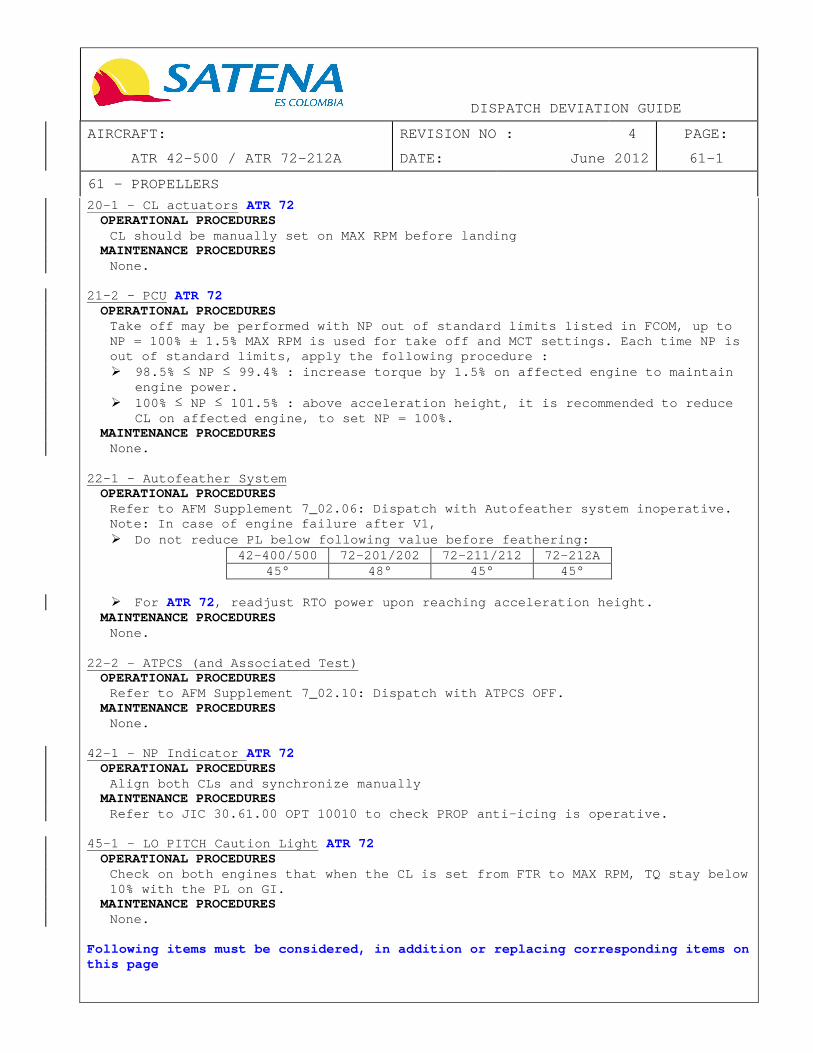
DISPATCH DEVIATION GUIDE
AIRCRAFT: REVISION NO : 4 PAGE:
ATR 42-500 / ATR 72-212A DATE: June 2012 61-1
61 – PROPELLERS
20-1 – CL actuators ATR 72 OPERATIONAL PROCEDURES
CL should be manually set on MAX RPM before landing MAINTENANCE PROCEDURES
None. 21-2 - PCU ATR 72
OPERATIONAL PROCEDURES Take off may be performed with NP out of standard l imits listed in FCOM, up to NP = 100% ± 1.5% MAX RPM is used for take off and M CT settings. Each time NP is out of standard limits, apply the following procedu re : � 98.5% ≤ NP ≤ 99.4% : increase torque by 1.5% on affected engine to maintain
engine power. � 100% ≤ NP ≤ 101.5% : above acceleration height, it is recommen ded to reduce
CL on affected engine, to set NP = 100%. MAINTENANCE PROCEDURES
None. 22-1 - Autofeather System
OPERATIONAL PROCEDURES Refer to AFM Supplement 7_02.06: Dispatch with Auto feather system inoperative. Note: In case of engine failure after V1, � Do not reduce PL below following value before feath ering:
42-400/500 72-201/202 72-211/212 72-212A 45° 48° 45° 45°
� For ATR 72 , readjust RTO power upon reaching acceleration hei ght.
MAINTENANCE PROCEDURES None.
22-2 - ATPCS (and Associated Test)
OPERATIONAL PROCEDURES Refer to AFM Supplement 7_02.10: Dispatch with ATPC S OFF.
MAINTENANCE PROCEDURES None.
42-1 - NP Indicator ATR 72
OPERATIONAL PROCEDURES Align both CLs and synchronize manually
MAINTENANCE PROCEDURES Refer to JIC 30.61.00 OPT 10010 to check PROP anti- icing is operative.
45-1 - LO PITCH Caution Light ATR 72
OPERATIONAL PROCEDURES Check on both engines that when the CL is set from FTR to MAX RPM, TQ stay below 10% with the PL on GI.
MAINTENANCE PROCEDURES None.
Following items must be considered, in addition or replacing corresponding items on this page

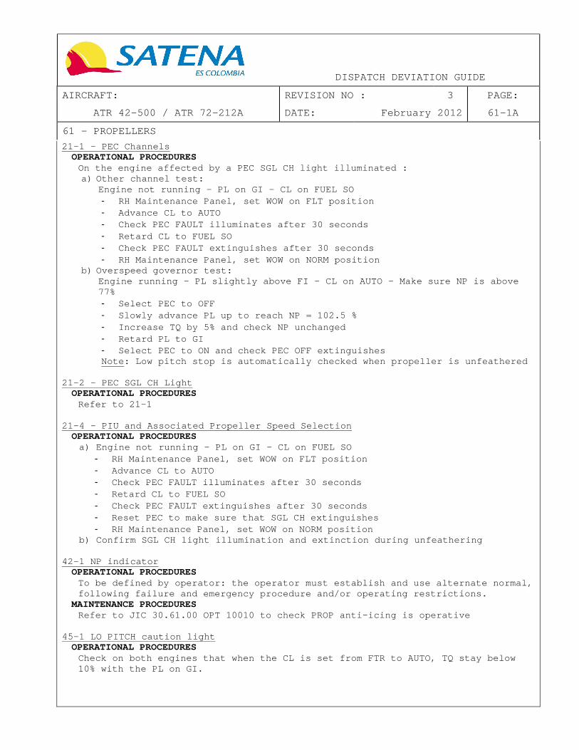
DISPATCH DEVIATION GUIDE
AIRCRAFT: REVISION NO : 3 PAGE:
ATR 42-500 / ATR 72-212A DATE: February 2012 61-1A
61 – PROPELLERS
21-1 - PEC Channels OPERATIONAL PROCEDURES
On the engine affected by a PEC SGL CH light illumi nated : a) Other channel test:
Engine not running – PL on GI – CL on FUEL SO - RH Maintenance Panel, set WOW on FLT position - Advance CL to AUTO - Check PEC FAULT illuminates after 30 seconds - Retard CL to FUEL SO - Check PEC FAULT extinguishes after 30 seconds - RH Maintenance Panel, set WOW on NORM position
b) Overspeed governor test: Engine running – PL slightly above FI – CL on AUTO – Make sure NP is above 77% - Select PEC to OFF - Slowly advance PL up to reach NP = 102.5 % - Increase TQ by 5% and check NP unchanged - Retard PL to GI - Select PEC to ON and check PEC OFF extinguishes Note: Low pitch stop is automatically checked when propeller is unfeathered
21-2 - PEC SGL CH Light
OPERATIONAL PROCEDURES Refer to 21-1
21-4 - PIU and Associated Propeller Speed Selection
OPERATIONAL PROCEDURES a) Engine not running – PL on GI – CL on FUEL SO
- RH Maintenance Panel, set WOW on FLT position - Advance CL to AUTO - Check PEC FAULT illuminates after 30 seconds - Retard CL to FUEL SO - Check PEC FAULT extinguishes after 30 seconds - Reset PEC to make sure that SGL CH extinguishes - RH Maintenance Panel, set WOW on NORM position
b) Confirm SGL CH light illumination and extinction du ring unfeathering 42-1 NP indicator
OPERATIONAL PROCEDURES To be defined by operator: the operator must establ ish and use alternate normal, following failure and emergency procedure and/or op erating restrictions.
MAINTENANCE PROCEDURES Refer to JIC 30.61.00 OPT 10010 to check PROP anti- icing is operative
45-1 LO PITCH caution light
OPERATIONAL PROCEDURES Check on both engines that when the CL is set from FTR to AUTO, TQ stay below 10% with the PL on GI.


DISPATCH DEVIATION GUIDE
AIRCRAFT: REVISION NO : 3 PAGE:
ATR 42-500 / ATR 72-212A DATE: February 2012 61-2
61 – PROPELLERS
50-1 - Propeller Brake OPERATIONAL PROCEDURES
None. MAINTENANCE PROCEDURES
- Refer to JIC 61.51.67. DNZ 10000 51-3 - PROP BRK READY LT (if applicable)
OPERATIONAL PROCEDURES • If propeller brake releasing is needed
BLUE HYD PRESS............................CHECK 300 0 PSI PROP BRK..................................RELEASE UNLOCK LIGHT..............................CHECK EXT INGUISHES AFTER 6 SECONDS
• If PROP BRK warning is activated CL........................................FUEL SO
MAINTENANCE PROCEDURES None.


DISPATCH DEVIATION GUIDE
AIRCRAFT: REVISION NO : 3 PAGE:
ATR 42-500 / ATR 72-212A DATE: February 2012 73-1
73 – ENGINE FUEL AND CONTROL
13-1 - Idle Gate FAIL Alert OPERATIONAL PROCEDURES
Check IDLE GATE lever position: after take off (pus hed in) and at touch down (pulled out), and adjust if required.
MAINTENANCE PROCEDURES None.
15-1 - Fuel Heater
OPERATIONAL PROCEDURES None.
MAINTENANCE PROCEDURES • If TOO LOW TEMP
Fuel anti icing additive for all fuel (JET A, JET A 1, JP5, RT, TS1): To be added in compliance with Engine Maintenance M anual 72-00-00 Table 9 Check of oil level:
Open left hinged cowl (435AL or 445AL). Check that oil level is to “FULL”. Close cowl(s).
• If TOO HIGH TEMP The aircraft fuel system must operate in its normal configuration.
23–1 - PWR MGT Rotary Selector
SEE DDG 73 PAGE 1A, FOR THIS ITEM.

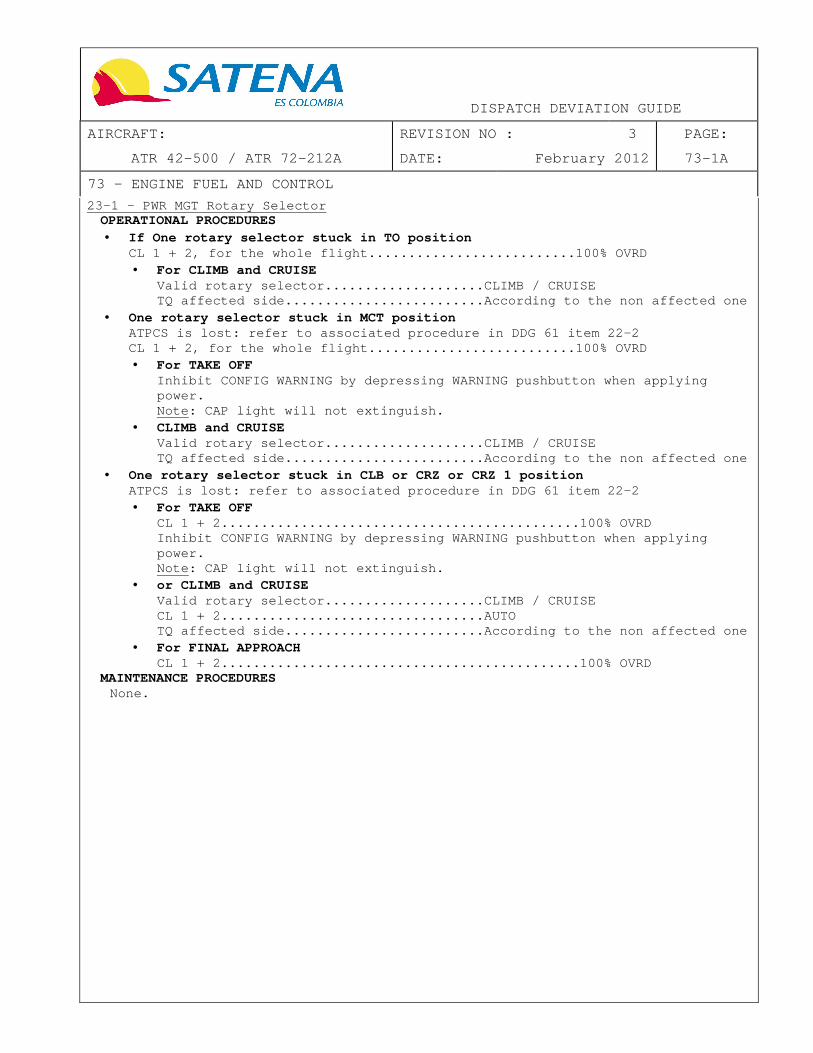
DISPATCH DEVIATION GUIDE
AIRCRAFT: REVISION NO : 3 PAGE:
ATR 42-500 / ATR 72-212A DATE: February 2012 73-1A
73 – ENGINE FUEL AND CONTROL
23–1 - PWR MGT Rotary Selector OPERATIONAL PROCEDURES • If One rotary selector stuck in TO position
CL 1 + 2, for the whole flight..................... .....100% OVRD • For CLIMB and CRUISE
Valid rotary selector....................CLIMB / CR UISE TQ affected side.........................According to the non affected one
• One rotary selector stuck in MCT position ATPCS is lost: refer to associated procedure in DDG 61 item 22-2 CL 1 + 2, for the whole flight..................... .....100% OVRD • For TAKE OFF
Inhibit CONFIG WARNING by depressing WARNING pushbu tton when applying power. Note: CAP light will not extinguish.
• CLIMB and CRUISE Valid rotary selector....................CLIMB / CR UISE TQ affected side.........................According to the non affected one
• One rotary selector stuck in CLB or CRZ or CRZ 1 po sition ATPCS is lost: refer to associated procedure in DDG 61 item 22-2 • For TAKE OFF
CL 1 + 2........................................... ..100% OVRD Inhibit CONFIG WARNING by depressing WARNING pushbu tton when applying power. Note: CAP light will not extinguish.
• or CLIMB and CRUISE Valid rotary selector....................CLIMB / CR UISE CL 1 + 2.................................AUTO TQ affected side.........................According to the non affected one
• For FINAL APPROACH CL 1 + 2........................................... ..100% OVRD
MAINTENANCE PROCEDURES None.

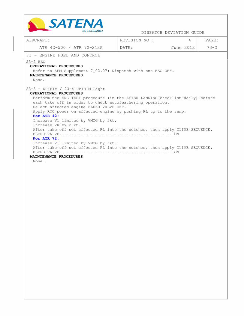
DISPATCH DEVIATION GUIDE
AIRCRAFT: REVISION NO : 4 PAGE:
ATR 42-500 / ATR 72-212A DATE: June 2012 73-2
73 – ENGINE FUEL AND CONTROL
23-2 EEC OPERATIONAL PROCEDURES
Refer to AFM Supplement 7_02.07: Dispatch with one EEC OFF. MAINTENANCE PROCEDURES
None. 23-3 - UPTRIM / 23-4 UPTRIM Light
OPERATIONAL PROCEDURES Perform the ENG TEST procedure (in the AFTER LANDIN G checklist–daily) before each take off in order to check autofeathering oper ation. Select affected engine BLEED VALVE OFF. Apply RTO power on affected engine by pushing PL up to the ramp. For ATR 42: Increase V1 limited by VMCG by 5kt. Increase VR by 2 kt. After take off set affected PL into the notches, th en apply CLIMB SEQUENCE. BLEED VALVE........................................ ........ON For ATR 72: Increase V1 limited by VMCG by 3kt. After take off set affected PL into the notches, th en apply CLIMB SEQUENCE. BLEED VALVE........................................ ........ON
MAINTENANCE PROCEDURES None.

DISPATCH DEVIATION GUIDE
AIRCRAFT: REVISION NO : 3 PAGE:
ATR 42-500 / ATR 72-212A DATE: February 2012 77-1
77 – ENGINE INDICATING
00-1 - AFU OPERATIONAL PROCEDURES
Refer to AFM Supplement 7_02.08: Dispatch with AFU / TSCU inoperative. MAINTENANCE PROCEDURES
This task is performed to deactivate the AFU and th en to avoid an untimely autofeather in flight:
Open C/B: ATR 42-400/500 and ATR 72 : "ENG CTL/ENG 1 (2) / FEATH CTL & AFU"
Open nacelle cowling left side. Disconnect:
ATR 42-400/500 and ATR 72 : AFU connector Secure and cap electrical connectors. Close nacelle cowling. Close C/B.
11-1 - NH Indicators
OPERATIONAL PROCEDURES When starting affected engine, select CL FTR 5 seco nds after START pushbutton has been depressed.
MAINTENANCE PROCEDURES None.
13-1 - TQ Indicator/TQ Indications
OPERATIONAL PROCEDURES • If TQ needle indication is inoperative
ATPCS.............................................. .....OFF Note: AFU must be considered inoperative ; refer to MEL 77 item 00-1 AFU .
• If TQ digital counter is inoperative � If associated EEC FAULT light is not illuminated
No penalties. � If associated EEC FAULT light is illuminated
Refer to MEL 73 item 23-2 EEC. • If TQ both pointer and (digital) counter is inopera tive
Refer to AFM Supplement 7_02.09: Dispatch with one TQ indicator inoperative.
MAINTENANCE PROCEDURES In case of dashes (---) on counter, check that no E EC fault code 39 (HBV) is recorded. Dispatch with inoperative HBV is not allowed.

DISPATCH DEVIATION GUIDE
AIRCRAFT: REVISION NO : 3 PAGE:
ATR 42-500 / ATR 72-212A DATE: February 2012 79-1
79 – OIL
32-1 Oil TEMP indication OPERATIONAL PROCEDURES
None. MAINTENANCE PROCEDURES
Refer to JIC 12.13.79 CHK 10000. 33-1 Oil PRESS indication
OPERATIONAL PROCEDURES None.
MAINTENANCE PROCEDURES Refer to JIC 79.34.00 OPT 10000.