miniature circuit breaker s 200 s - abb group · the miniature circuit breaker s 200 s ... derating...
TRANSCRIPT

Features – Screwless terminal on the load side allows easy, fast and save wiring
– Cables can be connected and removed without any tools – 2 cables up to 4 mm² are directly pluggable – Rigid cables and flexible cables with or without end sleeves can be
connected
– Best visibility conditions for the wiring due to the arrangement of the terminal openings
– Comfortable and exact voltage measurement on the load side due to the easily accessible measurement point
– Improved terminal on the supply side for cables up to 35 mm²
– Approved according to IEC/EN 60898-1 for global use – Fully compatible with all System pro M compact® devices and accessories
The miniature circuit breaker S 200 S extends the established ABB System pro M compact® product range. Thanks to the tool-free screwless terminal technology the S 200 S can be wired far more quickly and easily than standard screw-type circuit breakers. All kinds of cables can be connected. Rigid cables and flexible cables with end sleeves can be plugged in the screwless terminal directly. The easy-to-use, smooth-running terminal lever only needs to be pushed to connect flexible cables without end sleeves or to disconnect the wiring.
System pro M compact®
Miniature circuit breaker S 200 S
Data sheet
2C
DC
0210
01S
0010
2CD
C02
1002
S00
10
2 - 2CDC002137D0201
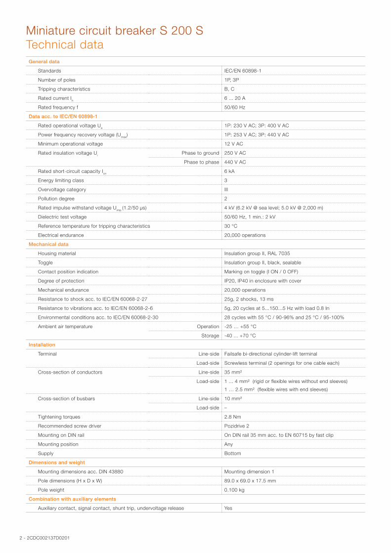
Miniature circuit breaker S 200 STechnical dataGeneral data
Standards IEC/EN 60898-1
Number of poles 1P, 3P
Tripping characteristics B, C
Rated current In 6 ... 20 A
Rated frequency f 50/60 Hz
Data acc. to IEC/EN 60898-1
Rated operational voltage Ue 1P: 230 V AC; 3P: 400 V AC
Power frequency recovery voltage (Umax) 1P: 253 V AC; 3P: 440 V AC
Minimum operational voltage 12 V AC
Rated insulation voltage Ui Phase to ground 250 V AC
Phase to phase 440 V AC
Rated short-circuit capacity Icn 6 kA
Energy limiting class 3
Overvoltage category III
Pollution degree 2
Rated impulse withstand voltage Uimp (1.2/50 µs) 4 kV (6.2 kV @ sea level; 5.0 kV @ 2,000 m)
Dielectric test voltage 50/60 Hz, 1 min.: 2 kV
Reference temperature for tripping characteristics 30 °C
Electrical endurance 20,000 operations
Mechanical data
Housing material Insulation group II, RAL 7035
Toggle Insulation group II, black, sealable
Contact position indication Marking on toggle (I ON / 0 OFF)
Degree of protection IP20, IP40 in enclosure with cover
Mechanical endurance 20,000 operations
Resistance to shock acc. to IEC/EN 60068-2-27 25g, 2 shocks, 13 ms
Resistance to vibrations acc. to IEC/EN 60068-2-6 5g, 20 cycles at 5...150...5 Hz with load 0.8 In
Environmental conditions acc. to IEC/EN 60068-2-30 28 cycles with 55 °C / 90-96% and 25 °C / 95-100%
Ambient air temperature Operation -25 … +55 °C
Storage -40 ... +70 °C
Installation
Terminal Line-side Failsafe bi-directional cylinder-lift terminal
Load-side Screwless terminal (2 openings for one cable each)
Cross-section of conductors Line-side 35 mm²
Load-side 1 ... 4 mm² (rigid or flexible wires without end sleeves)
1 … 2.5 mm² (flexible wires with end sleeves)
Cross-section of busbars Line-side 10 mm²
Load-side –
Tightening torques 2.8 Nm
Recommended screw driver Pozidrive 2
Mounting on DIN rail On DIN rail 35 mm acc. to EN 60715 by fast clip
Mounting position Any
Supply Bottom
Dimensions and weight
Mounting dimensions acc. DIN 43880 Mounting dimension 1
Pole dimensions (H x D x W) 89.0 x 69.0 x 17.5 mm
Pole weight 0.100 kg
Combination with auxiliary elements
Auxiliary contact, signal contact, shunt trip, undervoltage release Yes

2CDC002137D0201 - 3
Miniature circuit breaker S 200 STripping characteristics, internal resistance and power loss
Tripping characteristics
B characteristic C characteristic
2CD
C02
2026
F021
0
2CD
C02
2001
F021
0
Tripping characteristics acc. to IEC/EN 60898-1
Tripping characteristic
Rated current Thermal release 1) Electromagnetic release 2)
Currents Tripping time Range of instantaneous tripping Tripping time
conventional non-tripping current
I1
conventional tripping current
I2
B 6 to 20 A 1.13 · In1.45 · In
> 1 h
< 1 h
3 · In 5 · In
0.1 … 45 s
< 0.1 s
C 6 to 20 A 1.13 · In
1.45 · In
> 1 h
< 1 h
5 · In10 · In
0.1 … 15 s
< 0.1 s
1) The thermal releases are calibrated to a nominal reference ambient temperature; for B and C the reference value is 30 °C. In the case of higher ambient temperatures, the current values fall by approx. 6 % for each 10 K temperature rise.
2) The indicated tripping values of electromagnetic tripping devices apply to a frequency of 50/60 Hz. The thermal release operates independent of frequency.
Internal resistance and power loss
Tripping characteristic Rated current In Internal resistance per pole 1) Power loss per pole 1)
A mΩ W
B, C 6 52.1 2.16
C 8 22.9 1.65
B, C 10 19.0 2.20
B, C 13 13.7 2.62
B, C 16 9.1 3.28
B, C 20 6.2 3.14
1) Internal resistances and power loss are subject to application-specific and environment-specific conditions and are therefore to be considered as typical values.
4 - 2CDC002137D0201
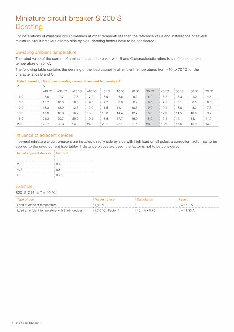
Miniature circuit breaker S 200 SDeratingFor installations of miniature circuit breakers at other temperatures than the reference value and installations of several miniature circuit breakers directly side by side, derating factors have to be considered.
Deviating ambient temperatureThe rated value of the current of a miniature circuit breaker with B and C characteristic refers to a reference ambient temperature of 30 °C.
The following table contains the derating of the load capability at ambient temperatures from –40 to 70 °C for the characteristics B and C.
Rated current In
A
Maximum operating current at ambient temperature T
A
–40 °C –30 °C –20 °C –10 °C 0 °C 10 °C 20 °C 30 °C 40 °C 50 °C 60 °C 70 °C
6.0 8.0 7.7 7.5 7.2 6.9 6.6 6.3 6.0 5.7 5.3 4.9 4.5
8.0 10.7 10.3 10.0 9.6 9.2 8.8 8.4 8.0 7.5 7.1 6.5 6.0
10.0 13.3 12.9 12.5 12.0 11.5 11.1 10.5 10.0 9.4 8.8 8.2 7.5
13.0 17.3 16.8 16.2 15.6 15.0 14.4 13.7 13.0 12.3 11.5 10.6 9.7
16.0 21.3 20.7 20.0 19.2 18.5 17.7 16.9 16.0 15.1 14.1 13.1 11.9
20.0 26.7 25.8 24.9 24.0 23.1 22.1 21.1 20.0 18.9 17.6 16.3 14.9
Influence of adjacent devicesIf several miniature circuit breakers are installed directly side by side with high load on all poles, a correction factor has to be applied to the rated current (see table). If distance pieces are used, the factor is not to be considered.
No. of adjacent devices Factor F
1 1
2, 3 0.9
4, 5 0.8
≥ 6 0.75
ExampleS201S-C16 at T = 40 °C
Type of use Values to use Calculation Result
Load at ambient temperature In(40 °C) In = 15.1 A
Load at ambient temperature with 8 adj. devices In(40 °C), Factor F 15.1 A x 0.75 In = 11.33 A
2CDC002137D0201 - 5
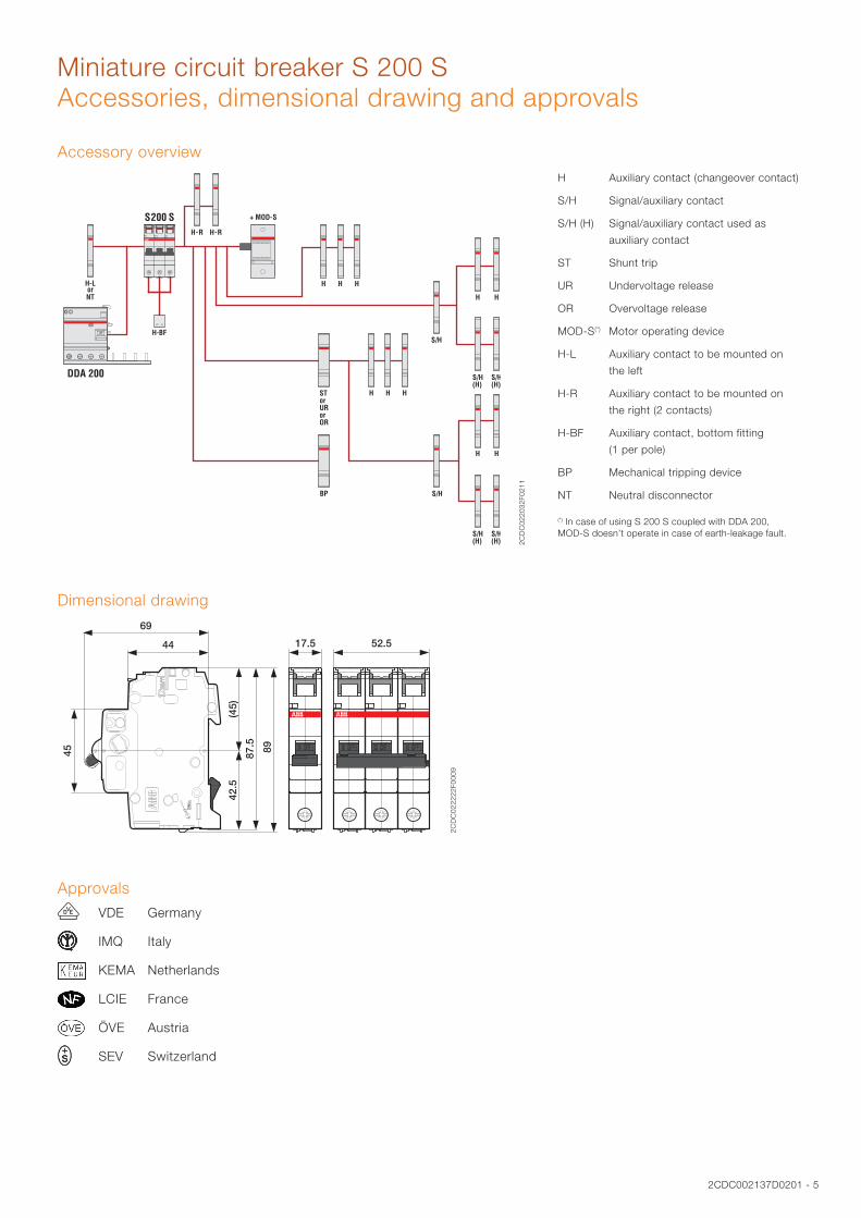
Miniature circuit breaker S 200 SAccessories, dimensional drawing and approvals
Accessory overview
2CD
C02
2032
F021
1
H Auxiliary contact (changeover contact)
S/H Signal/auxiliary contact
S/H (H) Signal/auxiliary contact used as
auxiliary contact
ST Shunt trip
UR Undervoltage release
OR Overvoltage release
MOD-S(*) Motor operating device
H-L Auxiliary contact to be mounted on
the left
H-R Auxiliary contact to be mounted on
the right (2 contacts)
H-BF Auxiliary contact, bottom fitting
(1 per pole)
BP Mechanical tripping device
NT Neutral disconnector
(*) In case of using S 200 S coupled with DDA 200, MOD-S doesn’t operate in case of earth-leakage fault.
Dimensional drawing
2CD
C02
2222
F000
9
Approvals
J VDE Germany
IMQ Italy
KEMA Netherlands
LCIE France
ÖVE Austria
SEV Switzerland
6 - 2CDC002137D0201
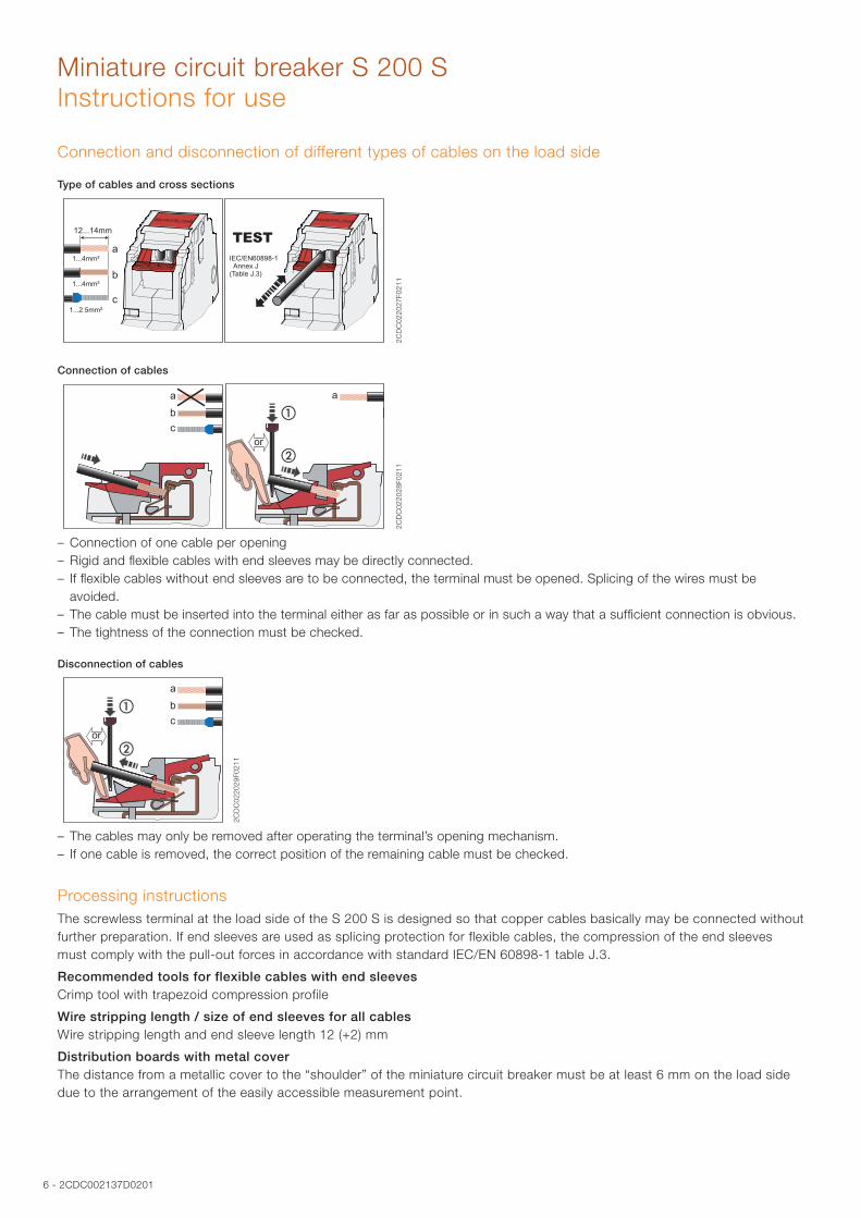
Miniature circuit breaker S 200 SInstructions for use
Connection and disconnection of different types of cables on the load side
Type of cables and cross sections
2CD
C02
2027
F021
1
Connection of cables
2CD
C02
2028
F021
1
– Connection of one cable per opening – Rigid and flexible cables with end sleeves may be directly connected. – If flexible cables without end sleeves are to be connected, the terminal must be opened. Splicing of the wires must be avoided.
– The cable must be inserted into the terminal either as far as possible or in such a way that a sufficient connection is obvious. – The tightness of the connection must be checked.
Disconnection of cables
2CD
C02
2029
F021
1
– The cables may only be removed after operating the terminal’s opening mechanism. – If one cable is removed, the correct position of the remaining cable must be checked.
Processing instructionsThe screwless terminal at the load side of the S 200 S is designed so that copper cables basically may be connected without further preparation. If end sleeves are used as splicing protection for flexible cables, the compression of the end sleeves must comply with the pull-out forces in accordance with standard IEC/EN 60898-1 table J.3.
Recommended tools for flexible cables with end sleeves Crimp tool with trapezoid compression profile
Wire stripping length / size of end sleeves for all cables Wire stripping length and end sleeve length 12 (+2) mm
Distribution boards with metal cover The distance from a metallic cover to the “shoulder” of the miniature circuit breaker must be at least 6 mm on the load side due to the arrangement of the easily accessible measurement point.

2CDC002137D0201 - 7
Miniature circuit breaker S 200 SOrder data
2C
DC
0210
01S
0010
S201S
2C
DC
0210
02S
0010
S203S
Tripping characteristic
Number of poles
Rated current In
Type Order code Packing unit
Weight per PCE
A PCE kg
B 1 6 S201S-B6 2CDS251002R0065 10 0.100
10 S201S-B10 2CDS251002R0105 10 0.100
13 S201S-B13 2CDS251002R0135 10 0.100
16 S201S-B16 2CDS251002R0165 10 0.100
20 S201S-B20 2CDS251002R0205 10 0.100
3 6 S203S-B6 2CDS253002R0065 1 0.300
10 S203S-B10 2CDS253002R0105 1 0.300
13 S203S-B13 2CDS253002R0135 1 0.300
16 S203S-B16 2CDS253002R0165 1 0.300
20 S203S-B20 2CDS253002R0205 1 0.300
C 1 6 S201S-C6 2CDS251002R0064 10 0.100
8 S201S-C8 2CDS251002R0084 10 0.100
10 S201S-C10 2CDS251002R0104 10 0.100
13 S201S-C13 2CDS251002R0134 10 0.100
16 S201S-C16 2CDS251002R0164 10 0.100
20 S201S-C20 2CDS251002R0204 10 0.100
3 6 S203S-C6 2CDS253002R0064 1 0.300
8 S203S-C8 2CDS253002R0084 1 0.300
10 S203S-C10 2CDS253002R0104 1 0.300
13 S203S-C13 2CDS253002R0134 1 0.300
16 S203S-C16 2CDS253002R0164 1 0.300
20 S203S-C20 2CDS253002R0204 1 0.300

ABB STOTZ-KONTAKT GmbHEppelheimer Straße 82 69123 Heidelberg, Germany Phone: +49 (0) 6221 7 01-0 Fax: +49 (0) 6221 7 01-13 25 E-Mail: [email protected]
You can find the address of your local sales organization on the ABB home page http://www.abb.com/contacts -> Low Voltage Products and Systems
Contact us
Note:We reserve the right to make technical changes or modify the contents of this document without prior notice. With regard to purchase orders, the agreed particulars shall prevail. ABB AG does not accept any responsibility whatsoever for potential errors or possible lack of information in this document.
We reserve all rights in this document and in the subject matter and illustrations contained therein. Any reproduction, disclosure to third parties or utilization of its contents – in whole or in parts – is forbidden without prior written consent of ABB AG.
Copyright© 2011 ABB All rights reserved
Ord
er n
um
ber
2C
DC
002
137
D02
01 p
rinte
d in
Ger
man
y (0
7/11
-5-Z
VD
)