mini vertomatic nc and laf 1000 standard & weaving · mini vertomatic nc and laf 1000 standard...
TRANSCRIPT
MINI VERTOMATIC NCAND LAF 1000
Standard & Weaving
Instruction manual and spare parts listRights reserved to alter specifications without notice
0777037002 REV 3 0705
CONTENTS
2
CONTENTS
WARNING……………………………………………………..3SAFETY ........................................................................... 4INTRODUCTION .............................................................. 6TECHNICAL DESCRIPTION............................................ 7
Control Box................................................................... 8Rising mechanism........................................................ 9Feeding box ................................................................ 10Technical data ............................................................ 15
INSTALLATION ............................................................. 16Mini Vertomatic NC assembly .................................. 20
OPERATION .................................................................. 22PARAMETERS............................................................... 24
Welding parameters ................................................... 25MAINTENANCE ............................................................. 26TROUBLE SHOOTING CHART..................................... 27WEAR AND SPARE PARTS.......................................... 28DIAGRAMS .................................................................... 29SPARE PARTS……………………………………….…….35OPTIONAL ..................................................................... 49
Weaving unit for MiniVertomatic NC 0899451880.... 49ADJUSTING OF WEAVING PARAMETERS ............ 51Adjusting the electrical limit positions .................. 52Wire diagram OSCILLATION UNIT.......................... 53MOTOR REGULATOR TYPE PM 5010 .................... 54
WARNING
3
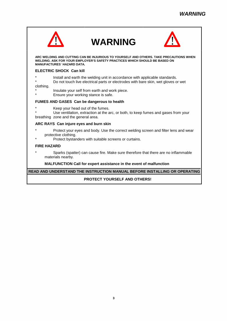
! WARNING !ARC WELDING AND CUTTING CAN BE INJURIOUS TO YOURSELF AND OTHERS. TAKE PRECAUTIONS WHENWELDING. ASK FOR YOUR EMPLOYER’S SAFETY PRACTICES WHICH SHOULD BE BASED ONMANUFACTURES` HAZARD DATA.
ELECTRIC SHOCK Can kill
* Install and earth the welding unit in accordance with applicable standards.* Do not touch live electrical parts or electrodes with bare skin, wet gloves or wetclothing.* Insulate your self from earth and work piece.* Ensure your working stance is safe.
FUMES AND GASES Can be dangerous to health
* Keep your head out of the fumes.* Use ventilation, extraction at the arc, or both, to keep fumes and gases from yourbreathing zone and the general area.
ARC RAYS Can injure eyes and burn skin
* Protect your eyes and body. Use the correct welding screen and filter lens and wearprotective clothing.
* Protect bystanders with suitable screens or curtains.
FIRE HAZARD
* Sparks (spatter) can cause fire. Make sure therefore that there are no inflammablematerials nearby.
MALFUNCTION Call for expert assistance in the event of malfunction
READ AND UNDERSTAND THE INSTRUCTION MANUAL BEFORE INSTALLING OR OPERATING
PROTECT YOURSELF AND OTHERS!

SAFETY
4
SAFETY
The user of an welding station has the overall responsibility for the safetymeasures that affect personnel working with the system or in its immediatevicinity.
The contents of these recommendations can be regarded as a supplement to thenormal regulations that apply at the workplace.
All manoeuvring must be carried out, according to given instructions, by personnelthat are conversant with the operation of the welding station.An incorrect manoeuvre, caused by an incorrect action, or an incorrect tripping ofa sequence of operations, can result in an abnormal situation that can affect theoperator as well as the machinery.
1. All personnel working with the welding station shall be conversant with:
its usage the placement of the emergency stop its operation applicable safety directives.
To facilitate this each electrical switch, pushbutton or potentiometer is fittedwith a sign or captioned sign which indicates the type of activated movementor engaged manoeuvre.
2. The workplace shall:
be free of mechanical parts, tools or other materials that can prevent theoperator’s movement within the working area.
be so organised that the requirements regarding accessibility to theemergency stop are fully met
3. Personal safety equipment
Always use prescribed personal safety equipment, for example, protectiveglasses, nonflammable clothing, protective gloves.
Do not wear loose fitting garments, for example, belts, arm bands, etc. whichcan become fastened.

SAFETY
5
4. Miscellaneous
Live parts are normally protected so as not to be touched.
Check that marked return cables are connected well. Repairs to electrical units may only be carried out by authorised
personnel. Essential firefighting equipment should be easily accessible at well signed
areas. Lubrication and maintenance must not be carried out while the welding
station is running.
6. Signs
CE
GOTHENBURGSWEDEN
Type
Ser. no.
Prod. year

INTRODUCTION
6
INTRODUCTION
The Mini Vertomatic NC is a light version of the Vertomatic NC. It allows the weldingin vertical up position of plates between 8 – 20 mm thickness and 8 – 34 mm in Mini Vertomatic NC weaving version. In standardversion, the length of the beads canreach 20m.
It uses the Electrogas process with wires of 1.6 and 2.4 mm diameter with CO2 and mixed gases.
As principal applications, the welding of ship hulls and the construction of storage tanks can be mentioned. The machine can alsorender great services into the shop everywhere it is possible to fix the plates with the weld in vertical position, for example thewelding of longitudinal seams of ferrules.
Advantages
The advantaged are evident when comparing, on diagram fig. 1, the speed of manual and automatic welding. Complementary tothat, an automatic vertical up weld shows no defects, especially due to the constant speed welding the whole length of the joint.
cm/min m/h
12 -
11 -
10 -
9 -
8 -
7 -
6 -
5 -
4 -
3 -
2 -
1 -
0 | | | | |
0 10 20 30 40 50 mm
7-
6-
5-
4-
3-
2-
1-
0
E
V
1
2
Fig. 1
E Thickness of platesV Welding speed1 Manual welding in a vertical position2 Verticalup automatic welding CO2 shielding

TECHNICAL DESCRIPTION
7
TECHNICAL DESCRIPTION
The welding machine
The installation is composed of the following elements:
CarriageThe self driving carriage are composed with a drive unit for right speed. It is guided by an conduit into the welding joint and thisconduit also supply the rear shoe with cooling water.
MachineThe welding machine consists of, se fig. 2:
Fig. 2
1
18 2
414 3
515 169 1310 611 712 8
17
1. Lifting hook2. Control box3. Wire reel4. Backing shoe unit5. Electrode motor6. Angular regulation of wire drive unit7. Forward/backwards regulation of the wire drive unit8. Side regulation of the wire drive unit9. Wire drive rolls10. Nozzle11. Drive roll pressure regulation12. Front shoe13. Photocell unit14. Backing shoe support15. Backing shoe fixation pin16. Regulation of backing shoe unit17. Regulation of front shoe
18. Spot light (option)
Welding head
The welding head consist of:
a 42 V gear motor to feed the electrode and with adjustable wire speed.
a wire drive rolls, 1,6 and 2,4 mm.
a wire guide nozzle, 1,6 and 2,4 mm.
a wheel control to adjust the wire feed nozzle exact into the weld.
a water cooled front shoe.
a water cooled back shoe arrangement.
TECHNICAL DESCRIPTION
8
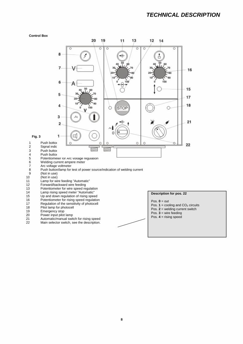
Control Box
Fig. 3
1 Push bottom/lamp for signal horn2 Signal indicator ”Horn”
3 Push button/lamp for water test and water flow (if there is a flow switch on the cooling unit)4 Push button/lamp for gas test and gas flow5 Potentiometer for Arc voltage regulation6 Welding current ampere meter7 Arc voltage voltmeter8 Push button/lamp for test of power source/indication of welding current9 (Not in use)
10 (Not in use)11 Lamp for wire feeding ”Automatic”12 Forward/backward wire feeding13 Potentiometer for wire speed regulation14 Lamp rising speed meter ”Automatic”15 Up and down regulation of rising speed16 Potentiometer for rising speed regulation17 Regulation of the sensitivity of photocell18 Pilot lamp for photocell19 Emergency stop20 Power input pilot lamp21 Automatic/manual switch for rising speed22 Main selector switch, see the description.
Description for pos. 22
Pos. 0 = outPos. 1 = cooling and CO2 circuitsPos. 2 = welding current switchPos. 3 = wire feedingPos. 4 = rising speed

TECHNICAL DESCRIPTION
9
Wire reel
a wire reel for maximum 15 kg.
Rising mechanism
The rising mechanism consists of:
a chain pulley. block with motor with variable speed, rising capacity: 250 kg
a chain with 5 m working length (20 m option)
a chain container for 5 m (chain container for 20 m option)
Fig. 4
1 Gear motor DC with safety couplingdevice
2 Rising hook3 Chain container4 Chain5 Connection hook

TECHNICAL DESCRIPTION
10
Feeding box
The feeding box contains the different feeding circuits of the installation parts. These circuits are commended by the control box,see fig. 4.
Fig. 5
1 Plug socket for cooling unit2 Plug socket for power source3 Plug socket for rising motor4 CO2 connection to bottles5 Plug socket for welding machine6 CO2 connection to welding machine

TECHNICAL DESCRIPTION
11
Power source LAF 1000
The welding rectifier LAF 1000, see at the separate manual.

TECHNICAL DESCRIPTION
12
Water cooler unit, see separate manual.

TECHNICAL DESCRIPTION
13
Water cooler unit, see separate manual.

TECHNICAL DESCRIPTION
14
Water cooler unit, see separate manual.

TECHNICAL DESCRIPTION
15
Cables and hoses
Leads cable and hose packages for 25 m distance between the machine and the feeding box.
Leads extension
Leads cable and hoses, max. length 25 m. (to be agree upon)
Technical data
Connection and control voltage:Wire speed, max.:Wire diameter:
42V DC.25 m/min. 1,6 mm and 2,4 mm
Plate thickness, standard:
Plate thickness with weaving device:
Height of plate, max.:
min. 8 mm.max. 20 mm.
min. 8 mm.max. 34 mm
max. 3000 mm.
Weights
Complete welding machine ready for welding.Welding machineCooling unitWelding rectifierCable and hoses
730 kg (670)60 kg (45)125 kg (80)345 kg200 kg

INSTALLATION
16
INSTALLATION
!See to that all installation an repairs to electrical units may only be carried out by authorisedpersonnel.
Connection cables and hoses
The connection between the rising mechanism, the welding machine, the feeding box, the power source and cooling unit is madewith following cable and hoses:Item following drawing 0899536000
Rising mechanism - Feeding box1 cable with 2 conductors (number 41)
Welding machine - Feeding box1 CO2 hose (number 40)1 control cable with 27 conductors (number 42)
Welding machine - Power source LAF 10001 welding cable (number 43)
Feeding box - Power source LAF 10001 cable with 7 conductors (number 32)
Welding machine - Cooling unit2 water hoses (number 44 and 45)
Feeding box - Cooling unit1 cable with 4 conductors (number 31)
Power source - Work piece1 welding return cable (number 37)1 reference cable (number 39)
The feeding of the installation is made through:
Power source1 cable with 4 conductors (number 28)
Cooling unit1 cable with 4 conductors (number 27)
CO2 bottles1 CO2 hose (number 36)

INSTALLATION
17
Cable and hoses, wiring diagram no. 0899536000
Option

INSTALLATION
18
Feeding voltage
Check carefully if the different part are connected with the right primary voltage of the feeding system.
Material preparation for test welding, see fig. 6.
In order to achieve good welding results, it may be necessarily to do some test:The test should be done in the same material as the production. As for the joint preparation it should be done according to themanual. The support plates must be welded so that they keep the plates straight and the gap remains at the same distance.
100
100
200
200
115 FLAT BAR 50XT L=500 (2 PCS)
START PLATE 100X100XT MM TACKWELDED
A-A
SUPPORT PLATET=15-20 MM
A-A
200
400

INSTALLATION
19
Sensor, drawing no: 0899400032
INSTALLATION
20
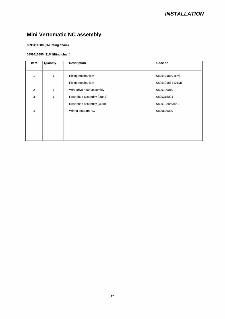
Mini Vertomatic NC assembly
0899410880 (5M lifting chain)
0899410880 (21M lifting chain)
Item Quantity Description Code no.
1
2
3
4
1
1
1
Rising mechanism
Rising mechanism
Wire drive head assembly
Rear shoe assembly (stand)
Rear shoe assembly (wide)
Wiring diagram RC
0899401880 (5M)
0899401881 (21M)
0899100010
0890315094
0899102880/881
0899536000

INSTALLATION
21
Assembly drawing 0899 400040
OPERATION
22
OPERATION
PREOPERATION SET UP
Fixing of the rising mechanism
To fix correctly the rising mechanism, a fixing point will be mounted in the prolongation of the joint 1 m above the end of the joint.
!Following the kind of construction, this fixing point should be studied for each case separately.
Controls
When the machine is suspended, control the correct working of:
the rising motor the wire motor the remote control the remote control of the power source the remote control of cooling unit the remote control of the gas feeding
Put the wire into the weld nozzle and feed some meters of wire through the nozzle while adjusting the correct pressure on thefeeding rolls.
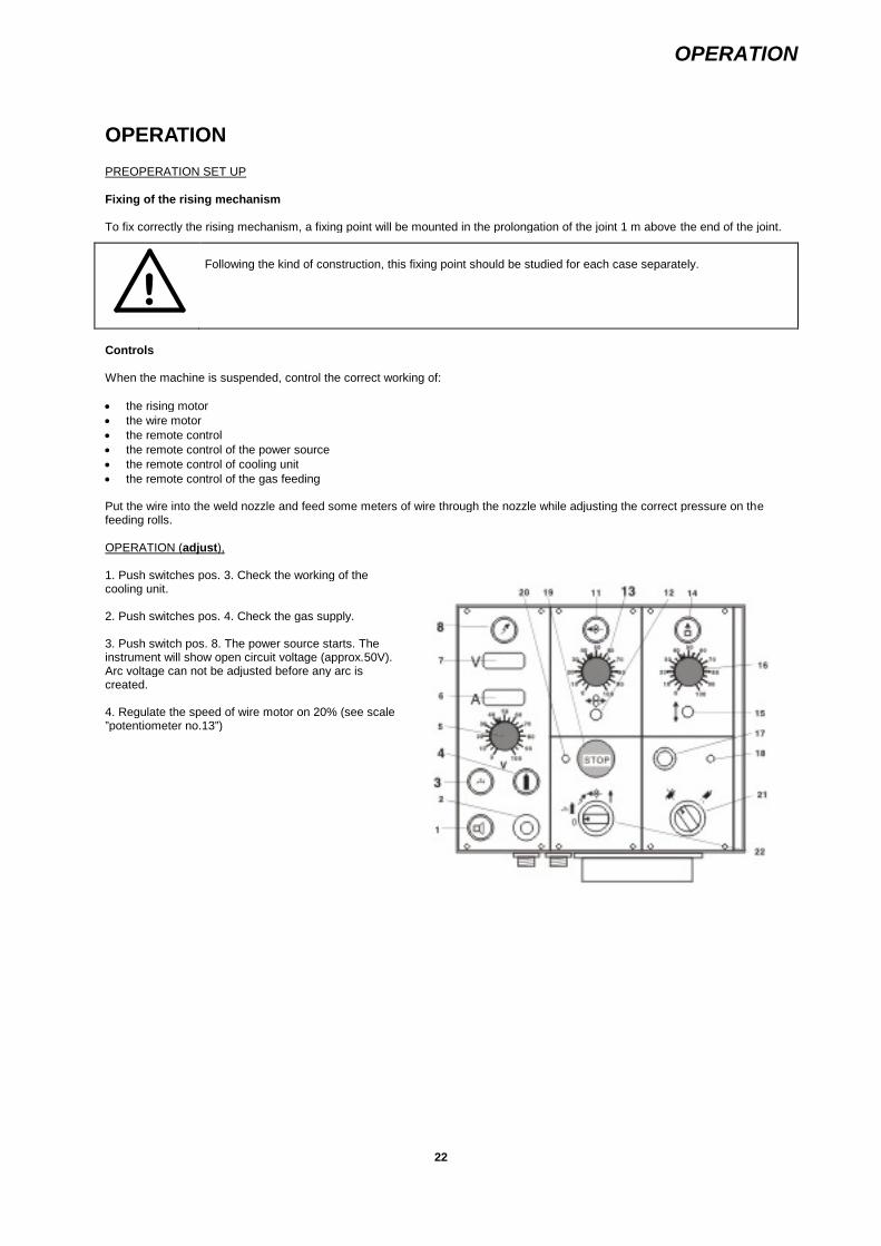
OPERATION (adjust),
1. Push switches pos. 3. Check the working of thecooling unit.
2. Push switches pos. 4. Check the gas supply.
3. Push switch pos. 8. The power source starts. Theinstrument will show open circuit voltage (approx.50V).Arc voltage can not be adjusted before any arc iscreated.
4. Regulate the speed of wire motor on 20% (see scale”potentiometer no.13”)
OPERATION
23
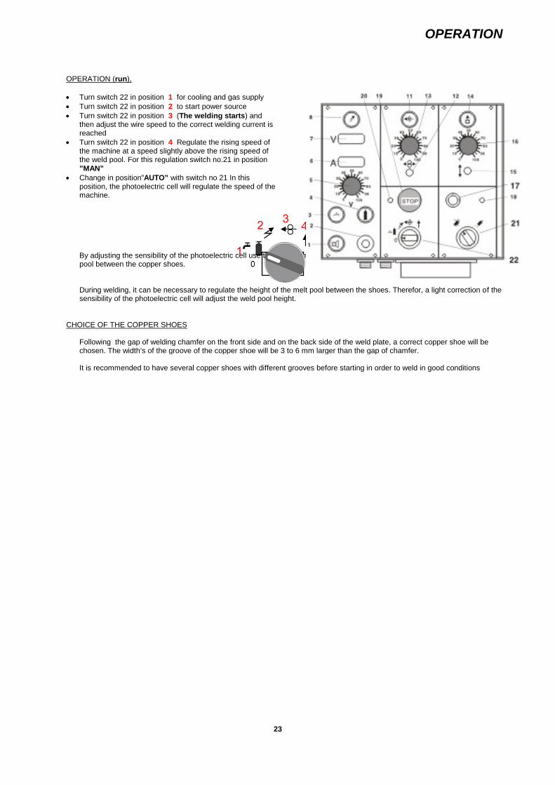
OPERATION (run),
Turn switch 22 in position 1 for cooling and gas supply Turn switch 22 in position 2 to start power source Turn switch 22 in position 3 (The welding starts) and
then adjust the wire speed to the correct welding current isreached
Turn switch 22 in position 4 Regulate the rising speed ofthe machine at a speed slightly above the rising speed ofthe weld pool. For this regulation switch no.21 in position”MAN”
Change in position”AUTO” with switch no 21 In thisposition, the photoelectric cell will regulate the speed of themachine.
By adjusting the sensibility of the photoelectric cell use the potentiometer no. 17. This regulation gives the position of the meltpool between the copper shoes.
During welding, it can be necessary to regulate the height of the melt pool between the shoes. Therefor, a light correction of thesensibility of the photoelectric cell will adjust the weld pool height.
CHOICE OF THE COPPER SHOES
Following the gap of welding chamfer on the front side and on the back side of the weld plate, a correct copper shoe will bechosen. The width’s of the groove of the copper shoe will be 3 to 6 mm larger than the gap of chamfer.
It is recommended to have several copper shoes with different grooves before starting in order to weld in good conditions
”MAN” ”AUTO”
PARAMETERS
24
PARAMETERS
!NOTE!For your one safety, be sure that you always use prescribed personalsafety equipment, for example, protective glasses, non-flammableclothing, protective gloves.Do not wear loose fitting garments, for example,belts, arm bands, etc. which can become fastened.
Description of the process
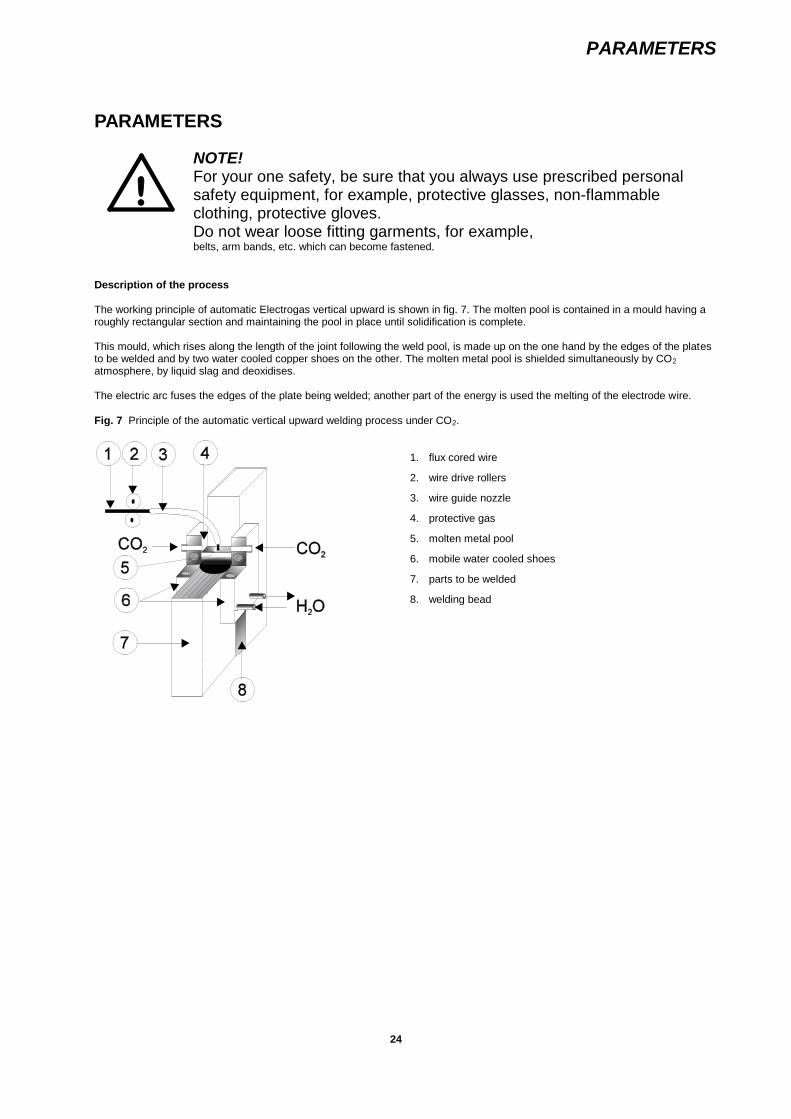
The working principle of automatic Electrogas vertical upward is shown in fig. 7. The molten pool is contained in a mould having aroughly rectangular section and maintaining the pool in place until solidification is complete.
This mould, which rises along the length of the joint following the weld pool, is made up on the one hand by the edges of the platesto be welded and by two water cooled copper shoes on the other. The molten metal pool is shielded simultaneously by CO2
atmosphere, by liquid slag and deoxidises.
The electric arc fuses the edges of the plate being welded; another part of the energy is used the melting of the electrode wire.
Fig. 7 Principle of the automatic vertical upward welding process under CO2.
1. flux cored wire
2. wire drive rollers
3. wire guide nozzle
4. protective gas
5. molten metal pool
6. mobile water cooled shoes
7. parts to be welded
8. welding bead

PARAMETERS
25
Welding parameters
A. Butt welds with I preparation B. V welds preparation(straight edges)
s
e
b
a
e
Rear shoe kit0899102881
Rear shoe kit0890315094 alt. 0899102880
Plate
Gap between Welding Welding Welding Deposited Wire Front Rear Welding
thickness
emm
platess
mm
current
A
voltage
V
speed
m/h
metal
kg/h
consumption
kg/m
shoe
(•)
shoe
(•)
ØWire
(mm)
CO2”Flow
(l/min)a b
10 1520 68 350400 2831 10,0 1,20 1,35 22x2,50899200015
12x20890311112
1,6 ±20
12 1520 420480 2830 5,00 2,10 2,30 22x2,50899200015
12x20890311112
1,6 ±20
15 1520 450520 3032 4,50 2,40 2,70 22x2,50899200015
12x20890311112
1,6 ±20
15 1520 68 450520 2931 5,9 2,20 2,45 22x2,50899200015
12x20890311112
1,6 ±20
20 1520 560620 3234 3,70 3,10 3,40 22x2,50899200015
12x20890311112
1,62,4
±20
20 1822 68 560620 3032 4,9 2,65 3,05 24x2,50899200007
12x20890311112
2,4 ±20
(•) : Dimensions of copper shoe are an indication
These Tables show the preparation in usual practice. In case of high tensile steels, for which particular properties in the heataffected zone are required, please contact our company. For butt and V welds, the process uses a mobile back shoe, rising withthe front shoe. The parameters are recommended and may change from case to case.
MAINTENANCE
26
MAINTENANCE
The machine is composed of different elements and a minimum of maintenance:
Rising mechanism
Check the motor reducer and lubricate the reducer every 2000 hours.
Lubricate from time to time the chain. Action the rising security once a week to ensure it is correction function.
Welding machine
Expect the wear parts, only the motor reducer needs a control every 2000 hours.
The lubrication happens as for the rising mechanism.
Feeding box
No maintenance service needed.
Cooling unit
Expect the cleaning of filter; the cooling unit does not need any special maintenance.Check water level every day.
Control after a long period of rest if the centrifugal pump turns freely.
Check antifreeze on start of every winter.
Wear and spare parts
The wear pieces and recommended spare parts are given in table, see chapter Wear and spare parts.

TROUBLE SHOOTING CHART
27
TROUBLE SHOOTING CHART
DEFECTS CAUSES REMEDIES
Porosity in bead Lack of shield gas
Protection loose by wind or draughts
Cooling water in the joint
Control the electro valveControl the hoses for leaks
Protect the machine against wind anddaughters with a shield
Control the tightness of shoe and waterlead
Lack of penetration on one side of bead Bad positioning of the wire Put the wire more in the direction of sidewith lack of penetration
Lack of penetration on both sides of thebead
Too short arc Increase arc voltage or decrease weldingcurrent
Undercuts on both sides of the bead Too long arc
Too narrow shoe gap
Increase welding current or decrease arcvoltage
Control if the gap in the shoe is 5 mmlarger than the opening of the chamfer.Replace the shoe by a larger one.
Front shoe or rear shoe get stocked intothe material
Too high parametersToo slow rising
Increase parameter.Decrease rising mechanism

WEAR AND SPARE PARTS
28
WEAR AND SPARE PARTS
Recommended wear and spare parts for two years running.
IMPORTANT! Please by ordering; specify the fabrication number of the machine.
Item Quantity Description Code no.
11123456789
10
12345
6789
10111213
Min Max.
1 11 11 11 11 11 11 11 11 11 11 21 2
1 310 2510 2511
2 102 102 102 101 11 21 26 12
A) Spare parts
Rear shoe kit (standard Mini NC)Rear shoe kit (weaving Mini NC)Rear shoe kit (weaving Mini NC)PlateConduitPotentiometer for rising regulationPotentiometer for wire speed regulationAmmeterVoltmeterMain selector switch C 14Solenoid valve 24 V ACRelay OKS 24 V AC
B) Wear parts
Nozzle holder for 1,62,4 mmNozzle 2.4 mmNozzle 1.6 mmWire rolls 1.6 mmWire rolls 2.4 mm
Rear shoe 12 x 2Front shoe 22 x 2.5Front shoe 24 x 2.5Front shoe 28 x 2.5Inlet guideCO2 heaterGlass tape no. 27O-ring for distributor 13.1*2.62(for temperature110º C)
089031509408991028800899102881089031112508903111800890400056089954000108994000810899400080089940005208994000310899400079
08994001350890316624089031661608908871160890887124
08903111120899200015089920000708992000170899400009089940002108908444950899426001

DIAGRAMS
29
DIAGRAMS
Wiring diagram – 899536000Cable for welding machine (internal)
Stycklista/Part list 899413880(Q413000A.XLS)
PosItem
AntalQty
Artikel nrPart nr
Benämning DenominationAnmärkning
Remark880
21 0,5m 0772270002 Kabel (i motor) Cable (in motor) 2G1,0 mm²
21 1 0899400093 Kabelkontakt Plug Wire Motor
22 0,7m 0772270123 Kabel Cable 3G0,75 mm²
22 1 0899400094 Kabelkontakt Plug Shunt
33 0,7 0262613605 Ledning SO120 Cable SO120 120 mm²
33 1 0770693040 Kabelsko Cable shoe 120*16
33 1 0160360883 Kabelkoppling Cable plug OKC120
24 0,6m 0262613604 Ledning SO95 Cable SO95
24 1 0770693049 Kabelsko Cable shoe 95*10
30 1,6m 0770698003 Gasslang PVC Gas hose PVC 6,3mm
30 1 0899400134 Slangnippel Hose nipple Type1806 (R3/8”’1/4” hose)
30 1 0899460001 Fiberpackning Fibre packing Type 18320
30 1 0899400128 Kopplingskropp Connection body Type 1800NV
34 1m 0899400130 Gummislang Rubber hose D=13/20
34 2 F200013020 Slangklämma Hose clamp FZB 1320mm
34 1 0899400127 Slangnippel Hose nipple Type 1812 (R3/8”*½” hose)
34 1 0899400129 Slangnippel Hose nipple Type 18410MNV
35 1 0899400130 Gummislang Rubber hose D=13/20
35 1 F200013020 Slangklämma Hose clamp FZB 1320mm
35 2 0899400124 Avstängningsventil On/off valve Water
35 1 0899400127 Slangnippel Hose nipple Type 1812 (R3/8”*½” hose)
35 1 0899460001 Fiberpackning Fibre packing Type 18320
35 1 0899400129 Slangnippel Hose nipple Type 18410MNV
25 1,5m 0899553002 Gummislang Rubber hose D=10/17
25 2 F200011017 Slangklämma Hose clamp FZB 1117mm
26 1,5m 0899553002 Gummislang Rubber hose D=10/17
26 2 F200011017 Slangklämma Hose clamp FZB 1117mm

DIAGRAMS
30
Wiring diagram – 0899536000Cable for welding machine
Stycklista/Part list 0899550880
PosItem
Antal / Qty Artikel nrPart nr
Benämning DenominationAnmärkning
Remark880
42 1 0899541880Manöverkabelkomplett 25m
Control cablecomplete 25m
Feeding box – Mini NC
41 1 0899407880 Kabel komplett 25m Cable complete 25mFeeding box – Risingmachine
31 1 0899408880 Kabel komplett 5m Cable complete 5m Cooling unit – Feeding box
32 1 0899544880 Kabel komplett 5m Cable complete 5m LAF – Feeding box
43 1 0899411880Svetskabel komplett25m
Welding cablecomplete 25m
LAF – Mini NC
37 1 0899412880Återledare komplett10m
Return cablecomplete 10m
LAF - Work piece
40 1 0899418880 Slang, gas 25m Hose for gas 25m Feeding box – Mini NC
44 1 0899420880 Slang, vatten 25m Hose for water 25m Cooling unit Mini NC (in)
45 1 0899421880 Slang, vatten 25m Hose for water 25m Cooling unit Mini NC (out)
39 1 0899551880 Referenskabel, 10m Reference cable 10m LAF – Work piece
36 1 0899419880 Slang, gas 5m Hose for gas 5 m Gas bottle - Feeding box

DIAGRAMS
31

DIAGRAMS
32

DIAGRAMS
33
Wiring diagram – 0899536000Cable for welding machine, standard

DIAGRAMS
34
Drawing no: 0899537000
35
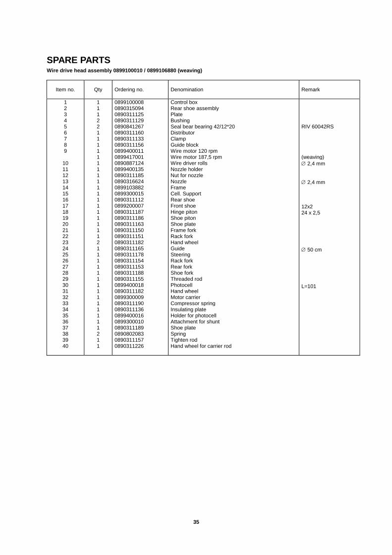
SPARE PARTSWire drive head assembly 0899100010 / 0899106880 (weaving)
Item no. Qty Ordering no. Denomination Remark
123456789
10111213141516171819202122232425262728293031323334353637383940
11122111111111111111111211111111111111211
08991000080890315094089031112508903111290890841267089031116008903111330890311156089940001108994170010890887124089940013508903111850890316624089910388208993000150890311112089920000708903111870890311186089031116308903111500890311151089031118208903111650890311178089031115408903111530890311188089031115508994000180890311182089930000908903111900890311136089940001608993000100890311189089080208308903111570890311226
Control boxRear shoe assemblyPlateBushingSeal bear bearing 42/12*20DistributorClampGuide blockWire motor 120 rpmWire motor 187,5 rpmWire driver rollsNozzle holderNut for nozzleNozzleFrameCell. SupportRear shoeFront shoeHinge pitonShoe pitonShoe plateFrame forkRack forkHand wheelGuideSteeringRack forkRear forkShoe forkThreaded rodPhotocellHand wheelMotor carrierCompressor springInsulating plateHolder for photocellAttachment for shuntShoe plateSpringTighten rodHand wheel for carrier rod
RIV 60042RS
(weaving) 2,4 mm
2,4 mm
12x224 x 2,5
50 cm
L=101
36
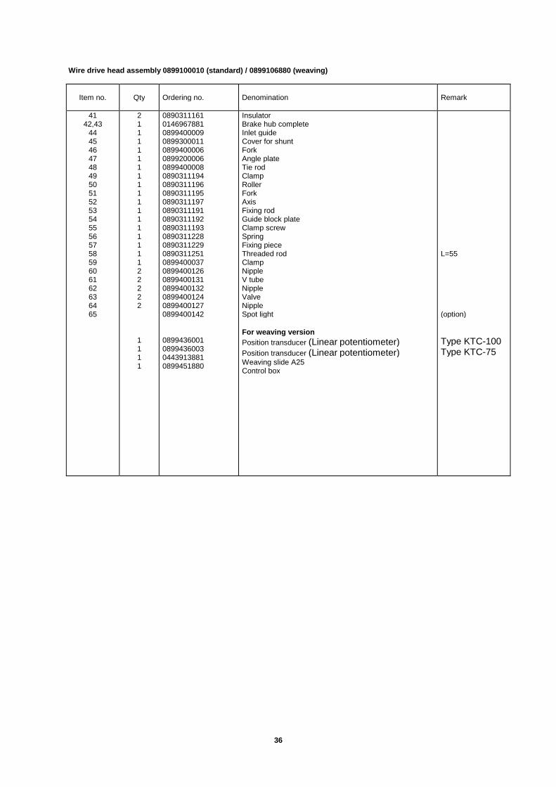
Wire drive head assembly 0899100010 (standard) / 0899106880 (weaving)
Item no. Qty Ordering no. Denomination Remark
4142,43
44454647484950515253545556575859606162636465
21111111111111111122222
1111
089031116101469678810899400009089930001108994000060899200006089940000808903111940890311196089031119508903111970890311191089031119208903111930890311228089031122908903112510899400037089940012608994001310899400132089940012408994001270899400142
0899436001089943600304439138810899451880
InsulatorBrake hub completeInlet guideCover for shuntForkAngle plateTie rodClampRollerForkAxisFixing rodGuide block plateClamp screwSpringFixing pieceThreaded rodClampNippleV tubeNippleValveNippleSpot light
For weaving version
Position transducer (Linear potentiometer)Position transducer (Linear potentiometer)Weaving slide A25Control box
L=55
(option)
Type KTC-100Type KTC-75

37

38
O P T I O N A L for wire drive head assembly – 0899100010 (standard) and 0899106880 (weaving)
Item no. Qty Ordering no. Denomination Remark
10
13
16
17
08908871160890887124
08903166160890316624
08903111110890311112089031111308903111150890311116
08993051110899305112089930511308993051150899305116
089920001108992000120899200013089920001408992000150899200007089920001608992000170899200018
Wire rolls (pair)Wire rolls (pair)
Nozzle for wireNozzle for wire
Rear shoe (for 0890315094)Rear shoe (for 0890315094)Rear shoe (for 0890315094)Rear shoe (for 0890315094)Rear shoe (for 0890315094)
Rear shoe wide (for 0899102880/881)Rear shoe wide (for 0899102880/881)Rear shoe wide (for 0899102880/881)Rear shoe wide (for 0899102880/881)Rear shoe wide (for 0899102880/881)
Front shoeFront shoeFront shoeFront shoeFront shoeFront shoeFront shoeFront shoeFront shoe
1.6 mm 2,4 mm
1,6 mm 2,4 mm
10x2 mm12x2 mm14x2 mm18x2,5 mm20x2,5 mm
10x2 mm12x2 mm14x2 mm18x2,5 mm20x2,5 mm
14x2 mm16x2 mm18x2,5 mm20x2,5 mm22x2,5 mm24x2,5 mm26x2,5 mm28x2,5 mm30x2,5 mm
39
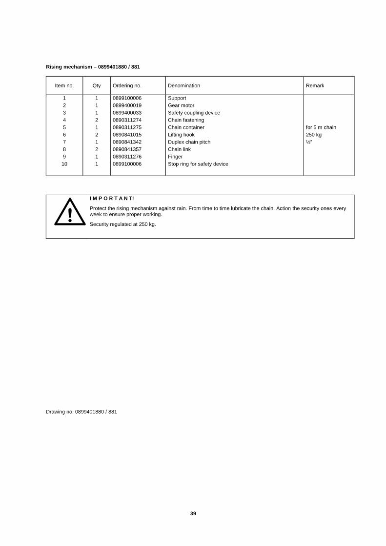
Rising mechanism – 0899401880 / 881
Item no. Qty Ordering no. Denomination Remark
1
2
3
4
5
6
7
8
9
10
1
1
1
2
1
2
1
2
1
1
0899100006
0899400019
0899400033
0890311274
0890311275
0890841015
0890841342
0890841357
0890311276
0899100006
Support
Gear motor
Safety coupling device
Chain fastening
Chain container
Lifting hook
Duplex chain pitch
Chain link
Finger
Stop ring for safety device
for 5 m chain
250 kg
½”
!I M P O R T A N T!
Protect the rising mechanism against rain. From time to time lubricate the chain. Action the security ones everyweek to ensure proper working.
Security regulated at 250 kg.
Drawing no: 0899401880 / 881
40

41
Drawing no: 0890315094

42
Rear shoe assembly - 0890315-094
Item no. Qty Ordering no. Denomination Remark
123456789
101112131415161718
2021
121
2111-111211221
24
0890311-1660899400-1410890311-169
0890311-1700890311-1730890311-1670890311-1800890311-1770890311-1310890311-1320890311-1740890311-1750890311-1710890311-1680890311-1720890311-2490890311-112
0899400-1150899102-021
Upper forkBearingAxis and washer
RollerShaftMiddle forkShoe carrier guide (conduit)Connection (part of pos. 8)AngleAngleRear shoe plateCopper tube (part of pos. 18)BlockUnder forkAxisSpringRear shoe
Rubber hoseRetaining ring
RIV608 2RS1
L40
L24
12x2
8/14 12,8-14,8
O P T I O N A L
Item no. Qty Ordering no. Denomination Remark
18 -----
0890311-1110890311-1120890311-1130890311-1150890311-116
Rear shoe (standard)Rear shoe (standard)Rear shoe (standard)Rear shoe (standard)Rear shoe (standard)
10x212x214x218x2,520x2,5

43
RM 6002
Front shoe Rear shoe
14x2 mm16x2 mm18x2,5 mm20x2,5 mm22x2,5 mm24x2,5 mm26x2,5 mm28x2,5 mm30x2,5 mm
089920001108992000120899200013089920001408992000150899200007089920001608992000170899200018
10x2 mm12x2 mm14x2 mm18x2,5 mm20x2,5 mm
08903111110890311112089031111308903111150890311116
Tolerance for preparation

44
Feeding box (for LAF1000)
Item no. Qty Ordering no. Denomination Remark
0899512880 A100 Feeding box
1 0899400073 Plug socket for cooling unit X27
2 0899400074 Plug socket for power source X26
3 0899400075 Plug socket for rising motor X25
4
5 0899400072 Plug socket for welding machine X21
6
7 0899400031 Solenoid switch
8 0899400030 Pressure switch
9 0899400028 Gas fittings
10 2 0899400079 Relay (for Cooling unit + Emergency stop) K1K5
11 0899400078 Interface card A100:1
12 0899400090 Inductor
(13) 0899300883 Gas unit complete
14 0770731001 Socket
15 0770732002 Diode module
16 0770819052 Lamp push button Green S2
17 0770820042 Contact block 2NC, LED
18 0770819053 Lamp push button Red S1
19 0770820038 Contact block 1NO, LED
20 0899535001 Electrolytic capacitor X
21 0899513880 LAF interfaceX) Only for A6 Travel Motor
Control box 0899100008Wiring diagram for control box – 0899538000
Item no. Qty Ordering no. Denomination

45
A300123456789
1036
40
A40011121319202237
A50014151617
182138
A20030313233343539
1
1
1
089920000808994000470899400049089940004808994000460899539001089940008108994000800899400041
0899400138
0899534880
08992000090899400042089940005708995400010899400051089940005808994000500899400139
08992000100899400043089940007608994000560899400053
089940005408994000520899400140
0899400117089940006508994001190899400118089940012108994001200899400222
A 300 Panel for meters and alarms (with all components)Push button/lamp for signal horn (red)Signal indicator ”horn”
Push button/lamp for water test and water flow (blue)Push button/lamp for gas test and gas flow (yellow)Arc voltage regulation potentiometer knobWelding current ampere meterArc voltage voltmeterPush button/lamp for test of power (green)(Not in use)(Not in use)A 300:1 Printed circuit (measurement and alarm board)A300:2 Printed circuit (PVM generator for arc voltage control)
A 400 Panel for wire motor (with all components)Lamp for wire feeding ”Automate” (green)Switch for forward/backward wire feedingPotentiometer for wire speed regulationSwitch for emergency stopPower input pilot lamp (green)Main selector switchA 400:1 Printed circuit (wire feeding)
A 500 Panel for rising motor ( with all components)Lamp for rising speed meter ”Automate” (green)Switch up and down regulation of rising speedPotentiometer for rising speed regulationPotentiometer for regulation of the sensitivity of the photo cellPilot lamp for photo electric cell (yellow)Switch for automatic/manual for travel functionA 500:1 Printed circuit (rising mechanism)
Plug socket for wire feeding motorPlug socket for projector lamp 24 V 20 WPlug socket for shuntPlug socket for photocellCircuit breaker for feed circuitPlug socket for connection to feeding boxA 200:1 Printed circuit (back plan card)

46
47
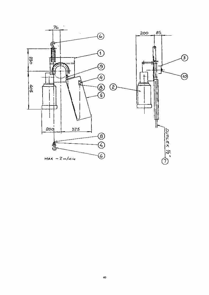
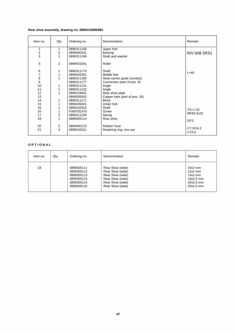
Rear shoe assembly, drawing no. 0899102880/881
Item no. Qty Ordering no. Denomination Remark
123
5
6789
10111213141516161718
2021
121
2
111
111
111121
24
089031116608994001410890311169
0899431001
08903111730899432001089031118008903111770890311131089031113208991040010899305002089031117108994350010899102016F00078147608903112490899305114
08904001150899102021
Upper forkBearingShaft and washer
Roller
ShaftMiddle forkShoe carrier guide (conduit)Connection (part of pos. 8)AngleAngleRear shoe plateCopper tube (part of pos. 18)BlockUnder forkShaftScrewSpringRear shoe
Rubber hoseRetaining ring, one ear
RIV 608 2RS1
L=40
6 L=32MF6S 6x32
20*2
7,9/14,315,5
O P T I O N A L
Item no. Qty Ordering no. Denomination Remark
18 089930511108993051120899305113089930511508993051140899305116
Rear Shoe (wide)Rear Shoe (wide)Rear Shoe (wide)Rear Shoe (wide)Rear Shoe (wide)Rear Shoe (wide)
10x2 mm12x2 mm14x2 mm18x2,5 mm20x2,0 mm20x2,5 mm

48
Drawing no. 0899102880/881
70mm

49
OPTIONAL
Weaving unit for Mini Vertomatic NC 0899451880

50
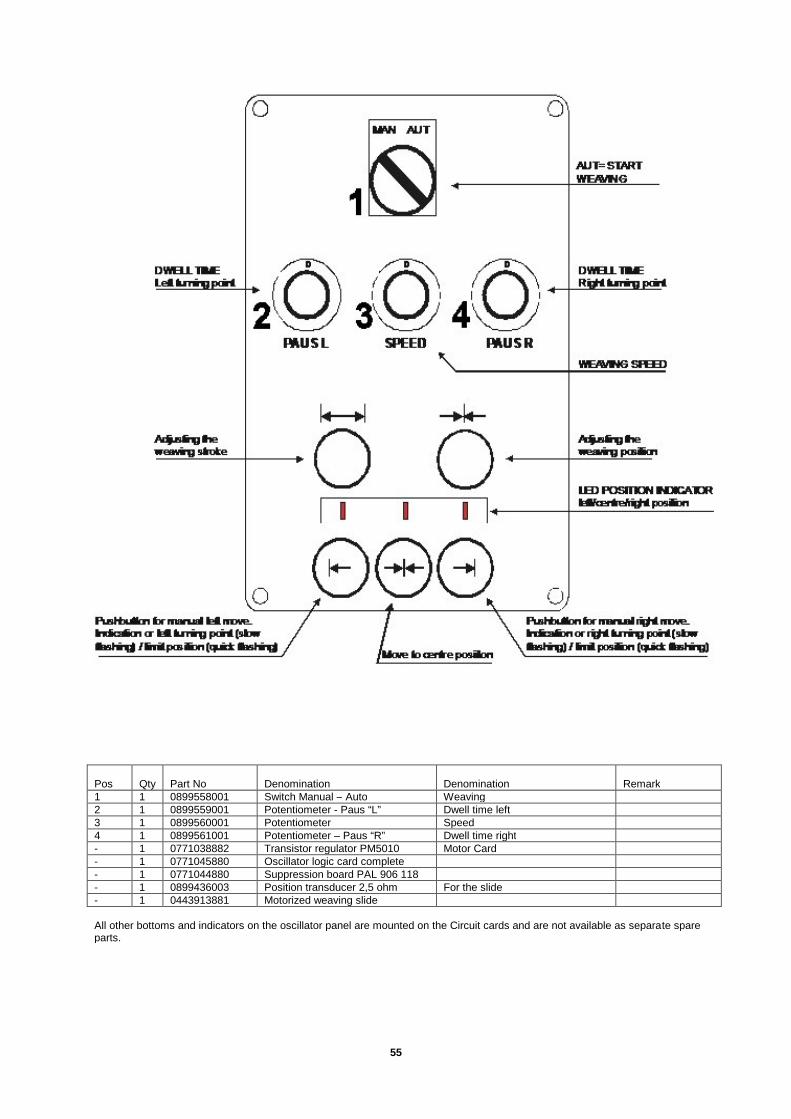
CONTROL BOX FOR WEAVING SLIDE 0899451880
DWELL TIMELeft turning point
DWELL TIMERight turning point
WEAVING SPEED
AUT= STARTWEAVING
Adjusting theweaving stroke
Adjusting theweaving position
LED POSITION INDICATORleft/centre/right position
Pushbutton for manual right move.Indication or right turning point (slowflashing) / limit position (quick flashing)
Pushbutton for manual left move.Indication or left turning point (slowflashing) / limit position (quick flashing)
Move to centre posiiton
0 0 0
MAN AUT
PAUS L PAUS RSPEED

51
ADJUSTING OF WEAVING PARAMETERS

52
Adjusting the electrical limit positions
Adjust the trim potentiometer P1 to max CW and P2 to min CCW who is located on the PC board behind the LED positionindicator.
Adjusting left limit positionMove the slide carefully to the point you wish to have the left limit point by using the left jog push pushbutton. Turn the trimpotentiometer P1 counter clockwise (CCW) to a position there the lamp in the left pushbutton starts flashing with 10Hz.
Adjusting right limit positionMove the slide carefully to the point you wish to have the right limit point by using the right jog push pushbutton. Turn the trimpotentiometer P2 clockwise (CW) to a position there the lamp in the right pushbutton starts flashing with 10Hz.
Now should the slide stop before it reach a dangerous area.
This adjusting sets how long distance the LED POSITION INDICATOR should represent of the position sensors total stroke.
NB If it is impossible to reach those limits you maybe have to adjust the mechanical attachment on the position sensor.

53
Wire diagram OSCILLATION UNIT
54
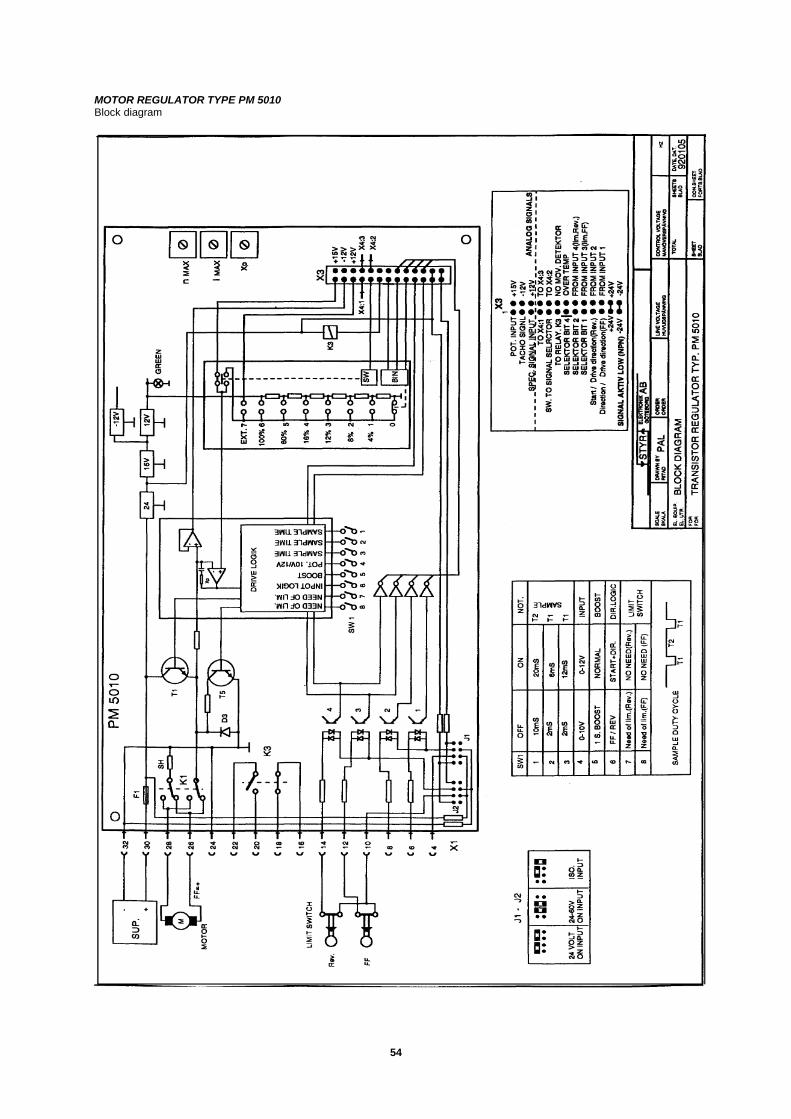
MOTOR REGULATOR TYPE PM 5010Block diagram
55
Pos Qty Part No Denomination Denomination Remark1 1 0899558001 Switch Manual – Auto Weaving2 1 0899559001 Potentiometer - Paus “L” Dwell time left3 1 0899560001 Potentiometer Speed4 1 0899561001 Potentiometer – Paus “R” Dwell time right- 1 0771038882 Transistor regulator PM5010 Motor Card- 1 0771045880 Oscillator logic card complete- 1 0771044880 Suppression board PAL 906 118- 1 0899436003 Position transducer 2,5 ohm For the slide- 1 0443913881 Motorized weaving slide
All other bottoms and indicators on the oscillator panel are mounted on the Circuit cards and are not available as separate spareparts.