mini usb-2 extender - gefen.com · the gefen mini usb-2 extender the mini usb-2 extender extends...
TRANSCRIPT
www.gefen.com
®Mini USB-2
Extender EXT-USB-MINI2
USER’S MANUAL
ASKING FOR ASSISTANCE
Rev A2
Technical Support:Telephone (818) 772-9100 (800) 545-6900
Fax (818) 772-9120
Technical Support Hours:8:00 AM to 5:00 PM Monday thru Friday PST
Write To:
Gefen LLCc/o Customer Service20600 Nordhoff St Chatsworth, CA 91311
NoticeGefen LLC reserves the right to make changes in the hard ware, packaging and
any accompanying doc u men ta tion without prior written notice.
Mini USB-2 Extender is a trademark of Gefen LLC
© 2010 Gefen LLC, All Rights ReservedAll trademarks are the property of their respective owners
CONTENTS
1 Introduction
2 Operation Notes
3 Features
4 Sender Panel Layout
5 Sender Panel Descriptions
6 Receiver Panel Layout
7 Receiver Panel Descriptions
8 Connecting And Operating The Mini USB-2 Extender
9 Network Cable Wiring Diagram
10 Troubleshooting
12 Specifi cations
13 Warranty
1
Congratulations on your purchase of the Mini USB-2 Extender. Your complete satisfaction is very important to us.
Gefen
Gefen delivers innovative, progressive computer and electronics add-on solutions that harness integration, extension, distribution and conversion technologies. Gefen’s reliable, plug-and-play products supplement cross-platform computer systems, professional audio/video environments and HDTV systems of all sizes with hard-working solutions that are easy to implement and simple to operate.
The Gefen Mini USB-2 Extender
The Mini USB-2 Extender extends any USB device up to 150 feet from the location of your computer, eliminating the 17.5 feet distance limitation of USB. The Mini USB-2 sender and receiver units use one CAT-5 cable for extension. It is optimized for applications where two devices, such as the keyboard and mouse, must be operated remotely. The USB-2 Extender can even be used to extend surveillance cameras for security purposes.
How It Works
The Mini USB-2 Extender sender unit is connected to the computer using the supplied USB cable. The remote peripheral(s) are connected to the receiver unit. A category-5 (CAT-5) cable is used to link the sender to the receiver.
INTRODUCTION
READ THESE NOTES BEFORE INSTALLING OROPERATING THE MINI USB-2 EXTENDER
• The Mini USB-2 Extender sender and receiver were designed to operate on USB type computers. DO NOT attempt to use this equip ment with any other type of device.
• Use the computer’s USB port when using a local keyboard that is not extended with the Mini USB-2 Extender sender unit.
• Only dedicated Category 5 UTP type cable (CAT-5) is recommended for this application (pin to pin). Filed termination should adhere to the TIA/EIA-568-B Scheduling
• The length of cable used to connect the Mini USB-2 Extender sender unit to the Mini USB-2 Extender receiver unit MUST NOT EXCEED 150 feet.
2
OPERATION NOTES
3
Features
• Extends any USB 1.1 device up to 150 feet (45 meters) using CAT-5 cable
• Requires no external power adapter
• Contains internal USB hub
• Provides support for any full-speed 12 Mb/s or low-speed 1.5Mb/s USB device
• Use either PC or Mac with USB keyboard/mouse
Package Includes
(1) Mini USB-2 Extender Sender unit(1) Mini USB-2 Extender Receiver unit(1) User Manual
FEATURES
4
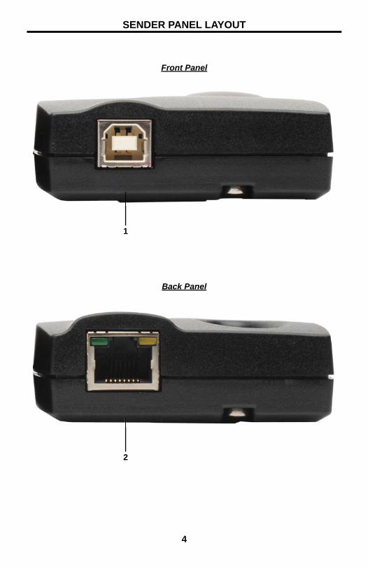
Front Panel
Back Panel
1
2
SENDER PANEL LAYOUT
5
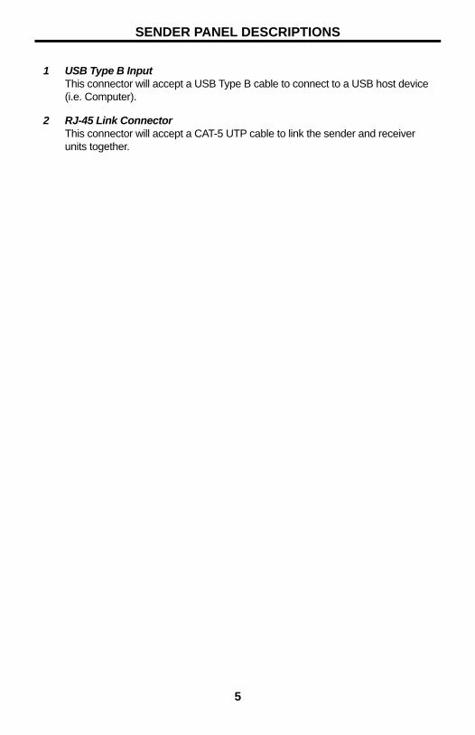
1 USB Type B InputThis connector will accept a USB Type B cable to connect to a USB host device (i.e. Computer).
2 RJ-45 Link ConnectorThis connector will accept a CAT-5 UTP cable to link the sender and receiver units together.
SENDER PANEL DESCRIPTIONS
6
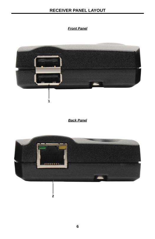
Front Panel
Back Panel
1
2
RECEIVER PANEL LAYOUT

7
1 USB Type A InputThis connector will accept a USB Type A cable to connect to a USB peripheral device (i.e. Keyboard & Mouse). Two USB peripherals can be connected at the same time.
2 RJ-45 Link ConnectorThis connector will accept a CAT-5 UTP cable to link the sender and receiver units together.
RECEIVER PANEL DESCRIPTIONS

8
How to Connect the Mini USB-2 Extender
1. Connect the USB host device to the USB Type B port on the Mini USB-2 Extender Sender unit using a user supplied USB Type A-B cable.
2. Connect the sender and receiver units together using a CAT-5 UTP cable.
NOTE: Maximum distance of CAT-5 cable should not exceed 150 feet. If fi eld terminating CAT-5 cabling, please adhere to the TIA/EIA-568-B scheduling. Please see page 9 for more information.
3. Connect up to two USB peripherals to the USB Type A ports on the Mini USB-2 Extender Receiver unit using user/device supplied USB cables.
How to Operate the Mini USB-2 Extender
No user confi guration or additional operations are necessary to operate the Mini USB-2 Extender.
CONNECTING AND OPERATING THE MINI USB-2 EXTENDER
1 2 3 4 5 6 7 8
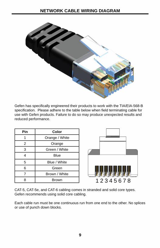
Gefen has specifi cally engineered their products to work with the TIA/EIA-568-B specifi cation. Please adhere to the table below when fi eld terminating cable for use with Gefen products. Failure to do so may produce unexpected results and reduced performance.
CAT-5, CAT-5e, and CAT-6 cabling comes in stranded and solid core types. Gefen recommends using solid core cabling.
Each cable run must be one continuous run from one end to the other. No splices or use of punch down blocks.
Pin Color1 Orange / White2 Orange3 Green / White4 Blue
5 Blue / White6 Green7 Brown / White8 Brown
9
NETWORK CABLE WIRING DIAGRAM
10
TROUBLESHOOTING
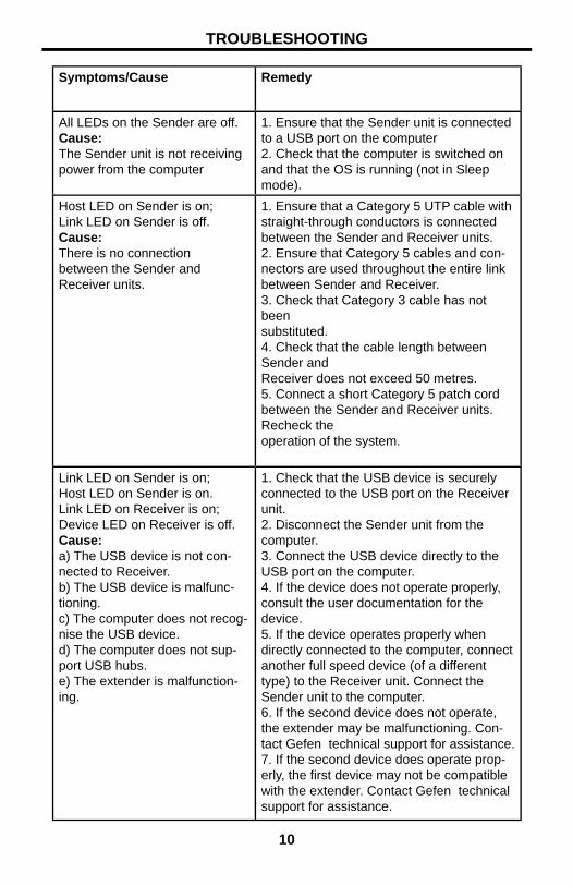
Symptoms/Cause Remedy
All LEDs on the Sender are off.Cause:The Sender unit is not receiving power from the computer
1. Ensure that the Sender unit is connected to a USB port on the computer2. Check that the computer is switched on and that the OS is running (not in Sleep mode).
Host LED on Sender is on;Link LED on Sender is off.Cause:There is no connectionbetween the Sender andReceiver units.
1. Ensure that a Category 5 UTP cable with straight-through conductors is connected between the Sender and Receiver units.2. Ensure that Category 5 cables and con-nectors are used throughout the entire link between Sender and Receiver.3. Check that Category 3 cable has not beensubstituted.4. Check that the cable length between Sender andReceiver does not exceed 50 metres.5. Connect a short Category 5 patch cordbetween the Sender and Receiver units. Recheck theoperation of the system.
Link LED on Sender is on;Host LED on Sender is on.Link LED on Receiver is on;Device LED on Receiver is off.Cause:a) The USB device is not con-nected to Receiver.b) The USB device is malfunc-tioning.c) The computer does not recog-nise the USB device.d) The computer does not sup-port USB hubs.e) The extender is malfunction-ing.
1. Check that the USB device is securely connected to the USB port on the Receiver unit.2. Disconnect the Sender unit from the computer.3. Connect the USB device directly to the USB port on the computer.4. If the device does not operate properly, consult the user documentation for the device.5. If the device operates properly when directly connected to the computer, connect another full speed device (of a different type) to the Receiver unit. Connect the Sender unit to the computer.6. If the second device does not operate, the extender may be malfunctioning. Con-tact Gefen technical support for assistance.7. If the second device does operate prop-erly, the fi rst device may not be compatible with the extender. Contact Gefen technical support for assistance.
11
TROUBLESHOOTING
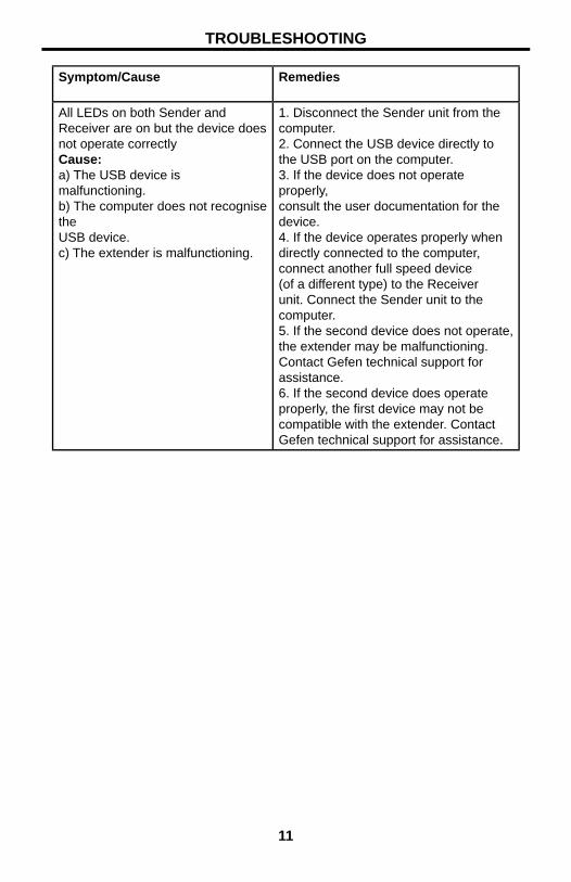
Symptom/Cause Remedies
All LEDs on both Sender and Receiver are on but the device does not operate correctlyCause:a) The USB device is malfunctioning.b) The computer does not recognise theUSB device.c) The extender is malfunctioning.
1. Disconnect the Sender unit from the computer.2. Connect the USB device directly to the USB port on the computer.3. If the device does not operate properly,consult the user documentation for the device.4. If the device operates properly when directly connected to the computer, connect another full speed device (of a different type) to the Receiver unit. Connect the Sender unit to the computer.5. If the second device does not operate, the extender may be malfunctioning. Contact Gefen technical support for assistance.6. If the second device does operate properly, the fi rst device may not be compatible with the extender. Contact Gefen technical support for assistance.
12
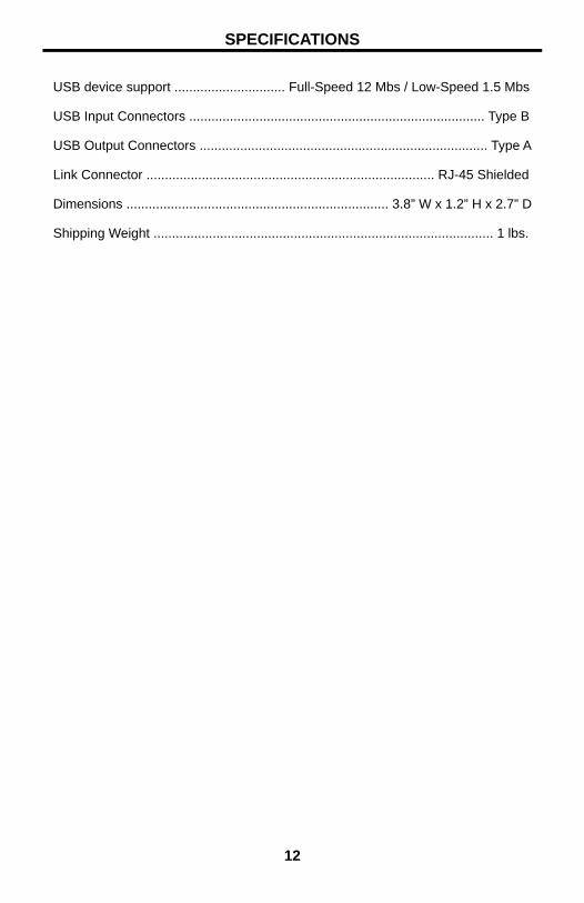
USB device support .............................. Full-Speed 12 Mbs / Low-Speed 1.5 Mbs
USB Input Connectors ................................................................................ Type B
USB Output Connectors .............................................................................. Type A
Link Connector .............................................................................. RJ-45 Shielded
Dimensions ....................................................................... 3.8” W x 1.2” H x 2.7” D
Shipping Weight ............................................................................................ 1 lbs.
SPECIFICATIONS
13
*EXT
-ma-
USB-
MINI
2* Rev A2
20600 Nordhoff St., Chatsworth CA 91311
1-800-545-6900 818-772-9100 fax: 818-772-9120
www.gefen.com [email protected]
Pb