mini-medical 90
DESCRIPTION
manual original esta en ingles...TRANSCRIPT

7/15/2019 Mini-medical 90
http://slidepdf.com/reader/full/mini-medical-90 1/132
250 Clearbrook Rd.
Elmsford, N.Y. 10523
(914) 592-6100
AFP
"Mini-Medical" Series
X-Ray Film Processors
September 15, 2005 0000061122 REV 04
Installation, Operation,Service & Parts Manual
7/15/2019 Mini-medical 90
http://slidepdf.com/reader/full/mini-medical-90 2/132
AFP Imaging Corporation warrants to the original purchaser that each newAFP product is free from defects in
workmanship and material for 12 months from date of installation or 18 months from date of sale, whichever occurs first.
If no warranty card is returned to AFP within 30 days of installation, the maximum warranty period will be 13 months from
date of shipment from AFP’s warehouse. In the event any product or component of equipment is replaced by AFP
under this warranty, such item is covered by this same warranty for the remainder of the original period or ninety daysfrom the date of installation, whichever is longer. AFP’s obligation during this warranty period is expressly limited to repair
or, at its discretion, replacement of non-expendable original equipment or components which it finds defective.
Upon authorization from AFP, a proper party asserting a claim under this warranty shall prepay all transportation costs
and return the equipment to a location specified by AFP. That party shall also bear all reasonable service and labor
charges incident to any warranty claim. This warranty does NOT APPLY (1) to any expendable parts including, but notlimited to lamps, photocells, or consumable supplies (2) to any AFP product or component which has been repaired or alteredwith parts or by persons not approved in writing by AFP, provided, however, that such approval is not to be
unreasonably withheld, or (3) to any product on which the serial number or name has been altered, defaced, or removed.
This warranty also shall NOT APPLY to any AFP product whose unsatisfactory performance or condition is due to:
- Instability of sensitized materials or chemical concentrations
and replenishing rates of chemical and wash water immersions or sequences;
- Lack of applied adequate quality production control procedures as
recommended by the sensitized material and chemical suppliers;
- Changes in characteristics or process procedures made by suppliers of
sensitized materials or chemicals after delivery of the AFP product to the purchaser;
- Lack of sufficient volume of sensitized materials for economical AFP product operation;
- Failure to follow the installation, maintenance, venting, or safety procedures
recommended for AFP product operation;
- Unusual physical or electrical stress;
- Accident, neglect, misuse, failure of electric power, air conditioning,
humidity control, transportation or causes other than ordinary use in the purposes
for which the product was intended;
THE ABOVE EXPRESS LIMITED WARRANTY IS IN LIEU OF ALL OTHER WARRANTIES, EXPRESSED OR IMPLIED AND THERE ARE NO WARRANTIES BEYOND THOSE STATED IN THIS DOCUMENT. THE IMPLIED
WARRANTIES OF MERCHANTABILITY AND FITNESS FOR A PARTICULAR PURPOSE AND ALL OTHER
WARRANTIES, EXPRESSED OR IMPLIED, OR INFERABLE FROM THE COURSE OF DEALING OR USAGE OF
TRADE, ARE EXCLUDED AND SHALL NOT APPLY TO THIS PRODUCT.
THE PROVISIONS FOR REPAIR OR REPLACEMENT OF DEFECTIVE PARTS PROVIDED IN THIS WARRANTYSHALL BE THE EXCLUSIVE AND SOLE REMEDY OF THE PURCHASER. AFP SHALL NOT BE LIABLE FOR
ANY OTHER DAMAGES (WHETHER IN TORT, DUE TO NEGLIGENCE OR OTHERWISE) INCLUDING BUT NOT
LIMITED TO, LOSS OF LABOR, TIME, MATERIALS, CUSTOMER PROFITS, GOODWILL, OR ANY OTHER
INDIRECT, SPECIAL, INCIDENTAL OR CONSEQUENTIAL DAMAGES IN CONNECTION WITH THE FURNISH-
ING, OPERATION OR FAULTY PERFORMANCE OF THIS PRODUCT. THIS EXCLUSIVE REMEDY SHALL NOTBE DEEMED TO HAVE FAILED OF ITS ESSENTIAL PURPOSE SO LONG AS AFP IS WILLING AND ABLE TOREPAIR OR REPLACE DEFECTIVE PARTS IN THE PRESCRIBED MANNER
THIS WRITING CONSTITUTES THE FINAL COMPLETE AND EXCLUSIVE EXPRESSION OF THE TERMS OF
WARRANTY AND REMEDY AS AGREED TO BY THE PARTIES TO THIS SALE. AFP NEITHER AUTHORIZES
NOR ADOPTS ANY STATEMENT MADE BY ANY REPRESENTATIVE WHICH DIFFERS FROM THE TERMS OF
THIS WRITING AND ALL SUCH STATEMENTS ARE SUPERSEDED BY THIS DOCUMENT.
AFP IMAGING CORP. 250 Clearbrook Road, Elmsford, N.Y. 10523
0000061122
WARRANTY

7/15/2019 Mini-medical 90
http://slidepdf.com/reader/full/mini-medical-90 3/132
REVISION RECORD
Title: AFP X-Ray Film Processors "Mini-Medical Series"
Document Number: 0000061122
Revision Effective Date Description
01 August 1, 1992 Initial Release
02 January 1, 1997 Total Publication Revision
03 April 26, 2001 Warranty Page Revised
04 December 15, 2001 Total Publication Revision

7/15/2019 Mini-medical 90
http://slidepdf.com/reader/full/mini-medical-90 4/132
7/15/2019 Mini-medical 90
http://slidepdf.com/reader/full/mini-medical-90 5/132
Index
Mini Med Series0000061122
AFP Mini-Medical
X-Ray Film Processor
Table Of Contents
Section 0 - Safety Information
Section 1 - Introduction
Content 1-1Description 1-1Operation 1-2
Capabilities 1-2Transport System 1-2...4Developer System 1-4Fixer System 1-4Developer & Fixer Replenishment 1-5Anti-Crystallization 1-5Wash System 1-5"No Plumbing" System (Optional) 1-5Dryer System 1-6Cover Interlock Switches 1-6General Specifications 1-7...8Accessories 1-9
Section 2 - Installation
Introduction 2-1Pre-Installation 2-1
Location 2-1Dimensions & Weight 2-2Through-the-Wall Installation 2-2Ventilation 2-2Electrical 2-2Plumbing 2-3"No Plumbing" System Option 2-3
Installation 2-4Set Up 2-4Assemble Stand 2-4Position Processor 2-4Connect Replenishment 2-4Replenish Mode 2-5Batch Mode 2-6Connect Plumbing 2-7"No Plumbing" Option 2-7Control Panel Position 2-8
I

7/15/2019 Mini-medical 90
http://slidepdf.com/reader/full/mini-medical-90 6/132
Index
Mini Med Series 0000061122
Section 2 - Installation (Continued)
Processor Checkout 2-9
Operational Checkout 2-9...10Transport Film 2-11Complete Checkout 2-11Processor Set Up Checklist 2-12Operational Checklist 2-13 Notes 2-14
Section 3 - Operation
Controls and Indicators 3-1User Controls 3-1
Power Switch 3-1
Manual Replenishment Switch 3-2Power ON LED 3-2Dev Temp LED 3-2Wait LED 3-2Low Dev LED 3-2Drain Valves 3-2Overflow Lines 3-2Top Cover Interlock Switch 3-2
Loading Chemicals 3-3Daily Start Up 3-4
Processor ON, Fill Wash Tank 3-4Check Developer and Fixer Levels 3-4Check Drive 3-4
Processing Film 3-5Shutdown and Daily Cleaning 3-5
Drain Wash Tank 3-5Clean Top Cover, Guides & Rollers 3-5Wipe Off Processor 3-5
Quality Control 3-6Developer 3-6Fixer 3-6
Replenishment 3-7Checklists for Daily Use 3-8
Startup 3-8Operation 3-8
Shutdown and Daily Cleaning 3-8
II

7/15/2019 Mini-medical 90
http://slidepdf.com/reader/full/mini-medical-90 7/132
Index
Mini Med Series0000061122
Section 4 - Maintenance
Maintenance Program 4-1
Maintenance Records 4-1Cleaning 4-1Mini-Medical Processor Maintenance Schedule 4-2
Daily 4-2Weekly 4-2Monthly 4-2Yearly 4-2
Mini-Medical Processor Maintenance Log 4-3Weekly Cleaning 4-4Monthly Cleaning 4-5
Clean Tanks 4-6Inspect Processor 4-6Prepare Fresh Chemicals 4-7
Lubrication 4-7Annual Maintenance 4-7
Removing Old Lubricants 4-8Lubrication Points 4-8
Section 5 - Service
Content 5-1Troubleshooting 5-1Service Procedures 5-2
Service Procedures Index 5-2Schematics 5-2
Troubleshooting Processor Problems 5-3...5Service Procedure 5-1, Main Drive Belt 5-6Service Procedure 5-1A, Film Sensors/Adjustments 5-7...8
Figure 5-1, Film Sensor Location Configurations 5-8Service Procedure 5-2, Servicing Circulation Pumps 5-9...11
Figure 5-2, Recirculation Pump Head, Early Style 5-11Figure 5-3, Recirculation Pump, Later Style 5-11
Service Procedure 5-3, Servicing Replenisher Pumps 5-12Service Procedure 5-4, Circuit Descriptions &
Calibration Procedures 5-13...17Developer Temperature Control 5-13Developer Temperature Calibration 5-14
Dryer Temperature Control 5-14Over Temperature Protection 5-15Dryer Temperature Calibration 5-15Replenishment Operation 5-16Replenishment Calibration 5-16Triacs & SCR's 5-17Outputs 5-17Fuses 5-17
III
7/15/2019 Mini-medical 90
http://slidepdf.com/reader/full/mini-medical-90 8/132
Index
Mini Med Series 0000061122
Section 5, Service (Cont'd)
Service Procedure 5-5, Theory of Operation 5-18...5-19
Solution Temperature Control 5-18Dryer Temperature Control 5-18Solution Level Sensor 5-19Automatic Shut-Off 5-19AC Interface Board 5-19
Waveforms & Voltages 5-20...5-21Schematics & Wiring Diagrams 5-22...5-30Main Wiring Diagram 5-22Dryer Rack Wiring Diagram 5-23AC Interface Board Schematic 5-24Logic Board Schematic 5-25Logic Board Layout 5-26AC Interface Board Layout 5-27
Ready Tone Generator Layouts & Schematics 5-28...5-29LED Board Layout & Schematic 5-30
IV
7/15/2019 Mini-medical 90
http://slidepdf.com/reader/full/mini-medical-90 9/132
Index
Mini Med Series0000061122
Section 6 - Parts
Introduction 6-1
How Parts Are Listed 6-1When Ordering Parts 6-1Maintenance Kit 6-1Documentation 6-1Part Listings
General Assembly 6-2Figure 6-1, General Assembly 6-3Figure 6-2a, Feed Tray & Control Chassis Assembly 6-4Figure 6-2b, Feed Tray & Control Chassis Assembly 6-5Figure 6-3, Drive System 6-6Figure 6-4, Tank/Frame Assembly 6-7Figure 6-5, Recirculation Pumps 6-8Recirculation Pump Parts (For P/N 0000021145) 6-8
Wet Rack Assembly 6-9Figure 6-6, Wet Rack Assembly, Top Roller Group 6-10Figure 6-7, Wet Racks, Bottom Roller Group 6-11Figure 6-8, Wet Racks, Film Guide Group 6-12Figure 6-9, Wash Rack, Squeegee Roller Group 6-13
Dryer Assembly, Front Exit 6-14Figure 6-10, Dryer Assembly, Full View 6-15Figure 6-11, Dryer Assembly, Side View 6-15
Dryer Assembly, Rear Exit 6-16Figure 6-12, Dryer Assembly, Rear Exit, Full View 6-17Figure 6-13, Dryer Assembly, Rear Exit, Side View 6-17
Plumbing Schematic (Early Style Parts Listing) 6-18
Figure 6-14, Plumbing Schematic (Early Style) 6-19Plumbing Schematic, (Later Style Parts Listing) 6-20
Figure 6-15, Plumbing Schematic (Later Style) 6-21 Notes 6-22
Section 7 - Accessories
Processor Support Stand 7-1Support Stand Parts 7-2Stand Turning Kit 7-3
Mounting Options Utilizing Turning Kit 7-4
Side Plumbing Kit 7-5Through-the-Wall Installation Kit, Front Exit 7-6Through-the-Wall Installation Kit, Rear Exit 7-7 Notes 7-8
V

7/15/2019 Mini-medical 90
http://slidepdf.com/reader/full/mini-medical-90 10/132

7/15/2019 Mini-medical 90
http://slidepdf.com/reader/full/mini-medical-90 11/132
AFP Mini-Medical
X-Ray Film Processors
- General Index -
Section 0 - Safety Information
Section 1 - Introduction
Section 2 - Installation
Section 3 - Operation
Section 4 - Maintenance
Section 5 - Service
Section 6 - Parts
Section 7 - Accessories
0000061122
Section 0 Safety Information

7/15/2019 Mini-medical 90
http://slidepdf.com/reader/full/mini-medical-90 12/132
7/15/2019 Mini-medical 90
http://slidepdf.com/reader/full/mini-medical-90 13/132
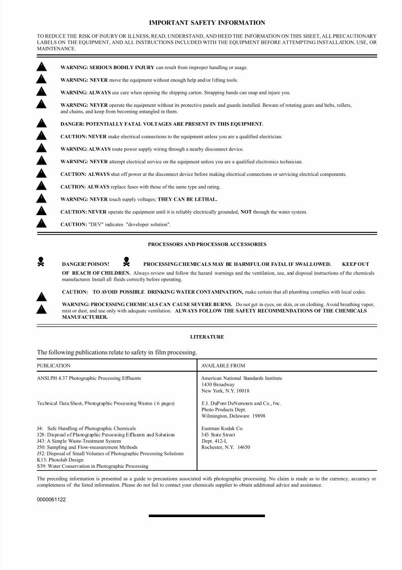
IMPORTANT SAFETY INFORMATION
TO REDUCE THE RISK OF INJURY OR ILLNESS, READ, UNDERSTAND, AND HEED THE INFORMATION ON THIS SHEET, ALL PRECAUTIONARY
LABELS ON THE EQUIPMENT, AND ALL INSTRUCTIONS INCLUDED WITH THE EQUIPMENT BEFORE ATTEMPTING INSTALLATION, USE, OR
MAINTENANCE.
WARNING: SERIOUS BODILY INJURY can result from improper handling or usage.
WARNING: NEVER move the equipment without enough help and/or l ifting tools.
WARNING: ALWAYS use care when opening the shipping carton. Strapping bands can snap and injure you.
WARNING: NEVER operate the equipment without its protective panels and guards installed. Beware of rotating gears and belts, rollers,
and chains, and keep from becoming entangled in them.
DANGER: POTENTIALLY FATAL VOLTAGES ARE PRESENT IN THIS EQUIPMENT.
CAUTION: NEVER make electrical connections to the equipment unless you are a qualified electrician.
WARNING: ALWAYS route power supply wiring through a nearby disconnect device.
WARNING: NEVER attempt electrical service on the equipment unless you are a qualified electronics technician.
CAUTION: ALWAYS shut off power at the disconnect device before making electrical connections or servicing electrical components.
CAUTION: ALWAYS replace fuses with those of the same type and rating.
WARNING: NEVER touch supply voltages; THEY CAN BE LETHAL.
CAUTION: NEVER operate the equipment until it is reliably electrically grounded, NOT through the water system.
CAUTION: "DEV" indicates "developer solution".
PROCESSORS AND PROCESSOR ACCESSORIES
DANGER! POISON! PROCESSING CHEMICALS MAY BE HARMFUL OR FATAL IF SWALLOWED. KEEP OUT
OF REACH OF CHILDREN. Always review and follow the hazard warnings and the ventilation, use, and disposal instructions of the chemicals
manufacturer. Install all fluids correctly before operating.
CAUTION: TO AVOID POSSIBLE DRINKING WATER CONTAMINATION, make certain that all plumbing complies with local codes.
WARNING: PROCESSING CHEMICALS CAN CAUSE SEVERE BURNS. Do not get in eyes, on skin, or on clothing. Avoid breathing vapor,
mist or dust, and use only with adequate ventilation. ALWAYS FOLLOW THE SAFETY RECOMMENDATIONS OF THE CHEMICALS
MANUFACTURER.
LITERATURE
The following publications relate to safety in film processing.
PUBLICATION AVAILABLE FROM
ANSI.PH 4.37 Photographic Processing Effluents American National Standards Institute
1430 Broadway
New York, N.Y. 10018
Technical Data Sheet, Photographic Processing Wastes ( 6 pages) E.I. DuPont DeNemours and Co., Inc.
Photo Products Dept.
Wilmington, Delaware 19898
J4: Safe Handling of Photographic Chemicals Eastman Kodak Co.
J28: Disposal of Photographic Processing Effluents and Solutions 343 State Street
J43: A Simple Waste-Treatment System Dept. 412-L
J50: Sampling and Flow-measurement Methods Rochester, N.Y. 14650
J52: Disposal of Small Volumes of Photographic Processing Solutions
K13: Photolab Design
S39: Water Conservation in Photographic Processing
The preceding information is presented as a guide to precautions associated with photographic processing. No claim is made as to the currency, accuracy or
completeness of the listed information. Please do not fail to contact your chemicals supplier to obtain additional advice and assistance.
0000061122

7/15/2019 Mini-medical 90
http://slidepdf.com/reader/full/mini-medical-90 14/132

7/15/2019 Mini-medical 90
http://slidepdf.com/reader/full/mini-medical-90 15/132
AFP Mini-Medical
X-Ray Film Processors
- General Index -
Section 0 - Safety Information
Section 1 - Introduction
Section 2 - Installation
Section 3 - Operation
Section 4 - Maintenance
Section 5 - Service
Section 6 - Parts
Section 7 - Accessories
0000061122
Section 1Introduction

7/15/2019 Mini-medical 90
http://slidepdf.com/reader/full/mini-medical-90 16/132

7/15/2019 Mini-medical 90
http://slidepdf.com/reader/full/mini-medical-90 17/132
Introduction
Mini Med Series0000061122
Content
This manual contains instructions for installing, using and maintaining the three differentmodels of the AFP Mini-Medical Series of X-Ray film processors. This series includes theMini-Medical, the Mini-Medical/90 and the Mini-Medical/EP processors. With the excep-tion of pre-set processing speed and developer temperatures, these three processors areidentical in appearance, operation, maintenance and service. Differences, where existing,will be noted in the text of this manual.
Description
The Mini-Medical system includes the processor, with daylight tight film feed tray, supportstand, replenishment tanks, necessary hoses and this manual.
Major processor sections and components are shown in Figure 1-1.
Figure 1-1, AFP Mini-Medical Series X-Ray Film Processor
1-1

7/15/2019 Mini-medical 90
http://slidepdf.com/reader/full/mini-medical-90 18/132
Introduction
Mini Med Series 0000061122
Operation
The processor is operated from the control panel. Basic processor functions are describedin the following paragraphs. Figure 1-2 is a diagram of the transport system.
Capabilities
Mini-Medical processors develop, fix, wash and dry exposed RP type medical X-ray filmsof all sizes, from 4" X 4" (10 X 10 cm) to 14" X 36" (35 X 91 cm).
Hourly production capacity of 14" X 17" (35 X 45 cm) sheets of film, at the indicated, pre-set, lead edge in to lead edge out time, is:
Model Lead-to-Lead Productivity
Mini-Medical 130 sec 55 sheets per hour Mini-Medical/90 90 sec 85 sheets per hour Mini-Medical/EP 180 sec 42 sheets per hour
Transport System
Four removable roller rack modules transport the material being processed through thedeveloper, fixer, wash and dryer sections.
The developer, fixer and wash sections make use of “Deep Tank” racks to maintain devel-oping quality and improve productivity. The dryer section includes a long path length
vertical dryer to assure material drying at short developing times, reduce space require-ments and return the film to the operator’s position for ease of pick-up.
All racks and rollers in the wet sections and dryer are driven from a common drive shaft bya fractional horsepower ac motor.
For ease of use, and accuracy of processing, developing times and developing temperaturesare factory set at the following values:
Model Dev. Time Developer Temp.
Mini-Medical 29 sec 90 Degrees f (32 C.)Mini-Medical/90 22 sec 95 Degrees f (35 C.)Mini-Medical/EP 44 sec 95 Degrees f (35 C.)
1-2
7/15/2019 Mini-medical 90
http://slidepdf.com/reader/full/mini-medical-90 19/132
Introduction
Mini Med Series0000061122
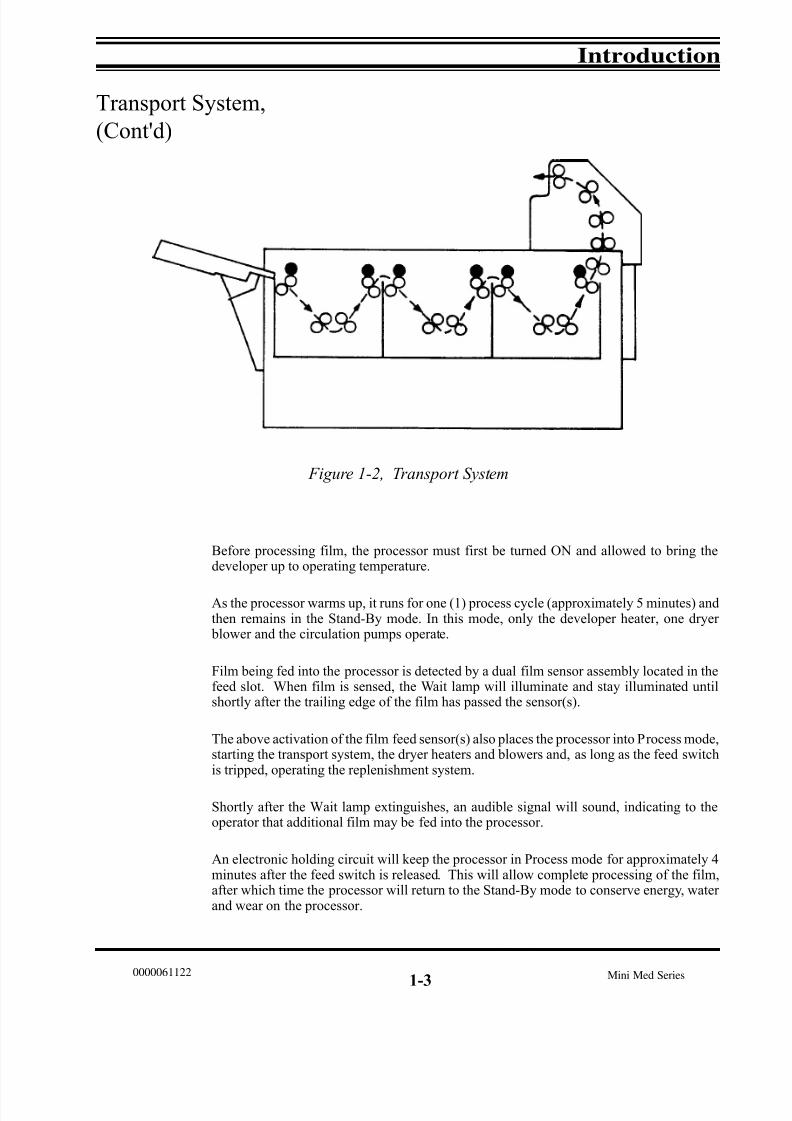
Transport System,
(Cont'd)
Before processing film, the processor must first be turned ON and allowed to bring thedeveloper up to operating temperature.
As the processor warms up, it runs for one (1) process cycle (approximately 5 minutes) andthen remains in the Stand-By mode. In this mode, only the developer heater, one dryer blower and the circulation pumps operate.
Film being fed into the processor is detected by a dual film sensor assembly located in thefeed slot. When film is sensed, the Wait lamp will illuminate and stay illuminated untilshortly after the trailing edge of the film has passed the sensor(s).
The above activation of the film feed sensor(s) also places the processor into Process mode,starting the transport system, the dryer heaters and blowers and, as long as the feed switchis tripped, operating the replenishment system.
Shortly after the Wait lamp extinguishes, an audible signal will sound, indicating to theoperator that additional film may be fed into the processor.
An electronic holding circuit will keep the processor in Process mode for approximately 4minutes after the feed switch is released. This will allow complete processing of the film,after which time the processor will return to the Stand-By mode to conserve energy, water and wear on the processor.
Figure 1-2, Transport System
1-3

7/15/2019 Mini-medical 90
http://slidepdf.com/reader/full/mini-medical-90 20/132
Introduction
Mini Med Series 0000061122
Transport System,
Cont'd)
Film is pulled into the processor by the input roller set on the developer rack. The film then
passes through the recirculating developer bath. As it leaves the developer, excess chemi-cals are squeegeed off by the exit rollers. This process is repeated in the fix, wash and dryer sections.
Processed and dried film is then deposited in the film delivery area on top of the processor.
Developer System
As the film passes through the developer tank, developer is continuously circulated andagitated around the rollers in the developer rack.
This developer circulation and agitation is provided by the developer chemistry being drawndown into the developer circulation pump, located in the base of the tank, and then being pumped back through the side of the tank, at a rate of approx. 2 gallons per minute.
The developer is replenished during operation by chemicals being drawn from the replen-ishment tank by a pump controlled by the replenishment circuit. This circuit operates the pump continuously, with the actual output rate, in ml/minute, being electronically con-trolled by the processor’s circuitry.
Developer heat is provided by a 500 watt heater located in a heat-exchanger below the tank.
Developer temperature is sensed by a temperature sensor, located in the bottom of the de-veloper tank.
Developer temperature is factory set at the values shown on Page 1-2, and may be re-adjusted by the installing technician to temperature values from ambient to 115 degrees f (46 C.)
Fixer System
The film is fixed in the fix tank. Fixer is agitated, circulated and replenished in the samemanner as the developer. The fixer is not heated.
1-4

7/15/2019 Mini-medical 90
http://slidepdf.com/reader/full/mini-medical-90 21/132
Introduction
Mini Med Series0000061122
Developer & Fixer
Replenishment
Mini-Medical Series processors are designed to operate in either “Batch” or “Replenish-
ment” mode. As such, replenishment chemicals may be replenished as necessary, with tank overflow being directed into a drain or collection container for disposal, or recycled untilexhausted, then discarded and fresh chemicals installed. For additional information refer tothe Operation and Maintenance sections of this manual.
Anti-Crystallization
To prevent the build-up of chemicals on the processing rollers, an anti-crystallization or “Jog” feature is built into all Mini-Medical processors.
This feature automatically runs the drive system at process speed for 20 seconds every 4
minutes, allowing fresh chemistry to be washed over the air-exposed rollers, effectively preventing crystallization of chemistry on the roller surfaces.
Wash System
The film being processed is washed in the wash tank before entering the dryer. The washwater solenoid is actuated during the processing cycle and refreshes the water in the washtank with tempered water from an external source.
“No Plumbing’’
System (Optional)
The available “No Plumbing” wash water recirculation system P/N 9992305003 (115 VAC)or P/N 9992305004 (230VAC) allows the installation of Mini-Medical processors withoutexternal plumbing connections.
When using this option, wash water is recirculated from a 7 gallon reservoir, to the proces-sor, and then back into the 7 gallon reservoir.
Processing chemistry (developer & fixer) is recirculated through each respective process-ing tank and replenishment container until its activity level is no longer satisfactory, at
which time it is drained and replaced.
1-5
7/15/2019 Mini-medical 90
http://slidepdf.com/reader/full/mini-medical-90 22/132
Introduction
Mini Med Series 0000061122
Dryer System
As film passes through the dryer, it is subjected to warm air from two linear infrared quartzheating elements and a pair of fans.
Upon leaving the dryer the film is deposited in the receiving bin.
Cover Interlock Switch
To prevent accidental injury from moving parts, a mechanical safety switch is interlockedwith the processor’s top cover. If the top cover is removed, the processor automaticallyshuts down.
1-6
7/15/2019 Mini-medical 90
http://slidepdf.com/reader/full/mini-medical-90 23/132
Introduction
Mini Med Series0000061122
General Specifications
Films
RP type medical X-Ray films and compatible chemicals designed for RP type processing.
Film Size
Minimum Size: 4" X 4" (10 X 10 cm)Maximum Size: 14" X 36" (35.6 C 91.4 cm)Base thicknesses 0.004 - 0.008"
Developing Time
Factory set as follows:
Model Dev. Time Linear Speed
Mini-Medical 29 sec 20" per minuteMini-Medical/90 22 sec 36" per minuteMin-Medical/EP 44 sec 10" per minute
Developer, Fix, & Wash
Systems
Capacity: 1.9 gallons (7.2 L.).
Temperature Control:
Developer: Factory Set as follows:
Mini-Medical 90 Degrees f. (32 C.)Mini-Medical/90 95 Degrees f. (35 C.)Mini-Medical/EP 95 Degrees f. (35 C.)
Fixer Ambient
Wash: Controlled by incoming water supply, .25 GPM (.95 LPM) during process and anti-crystallization cycle. There is no water flow in standby mode.
Dryer System
Temperature: Factory set at 120 degrees f. (49 C.).
1-7
7/15/2019 Mini-medical 90
http://slidepdf.com/reader/full/mini-medical-90 24/132
Introduction
Mini Med Series 0000061122
General Specifications,
Continued
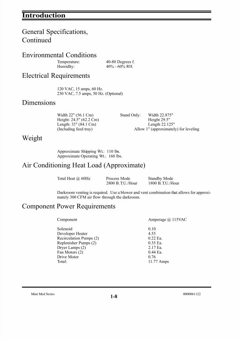
Environmental ConditionsTemperature: 40-80 Degrees f.Humidlty: 40% - 60% RH.
Electrical Requirements
120 VAC, 15 amps, 60 Hz.230 VAC, 7.5 amps, 50 Hz. (Optional)
Dimensions
Width 22" (56.1 Cm) Stand Only: Width 22.875"
Height: 24.5" (62.2 Cm) Height 29.5"Length: 33" (84.1 Cm) Length 22.125"(Including feed tray) Allow 1" (approximately) for leveling
Weight
Approximate Shipping Wt.: 110 lbs.Approximate Operating Wt.: 160 lbs.
Air Conditioning Heat Load (Approximate)
Total Heat @ 60Hz Process Mode Standby Mode2800 B.T.U./Hour 1800 B.T.U./Hour
Darkroom venting is required. Use a blower and vent combination that allows for approxi-mately 300 CFM air flow through the darkroom.
Component Power Requirements
Component Amperage @ 115VAC
Solenoid 0.10Developer Heater 4.55
Recirculation Pumps (2) 0.22 Ea.Replenisher Pumps (2) 0.35 Ea.Dryer Lamps (2) 2.17 Ea.Fan Motors (2) 0.44 Ea.Drive Motor 0.76Total: 11.77 Amps
1-8

7/15/2019 Mini-medical 90
http://slidepdf.com/reader/full/mini-medical-90 25/132
Introduction
Mini Med Series0000061122
AccessoriesStand Turn Kit (Allows sideways positioning of processor on stand for access to replenisher containers) P/N 9992305001.
Side Plumbing Kit (Moves plumbing from front to side of processor) P/N 9992305002.
“No Plumbing’ Wash Water Recirculation Kit.P/N 9992305003 (115 VAC)P/N 9992305004 (230 VAC)
Specifications are subject to change without prior notice.
1-9

7/15/2019 Mini-medical 90
http://slidepdf.com/reader/full/mini-medical-90 26/132
Introduction
Mini Med Series 0000061122

7/15/2019 Mini-medical 90
http://slidepdf.com/reader/full/mini-medical-90 27/132
AFP Mini-Medical
X-Ray Film Processors
- General Index -
Section 0 - Safety Information
Section 1 - Introduction
Section 2 - Installation
Section 3 - Operation
Section 4 - Maintenance
Section 5 - Service
Section 6 - Parts
Section 7 - Accessories
0000061122
Section 2 Installation

7/15/2019 Mini-medical 90
http://slidepdf.com/reader/full/mini-medical-90 28/132

7/15/2019 Mini-medical 90
http://slidepdf.com/reader/full/mini-medical-90 29/132
Mini Med Series 0000061122
Attention:
When testing or operating the processor with water (as opposed to chemistryj), there will be a
LOW LEVEL condition in effect which will disable the solution heater. This is due to the fact that water
by itself cannot conduct well enough. To prevent this, add 1-2 tablespoons of salt or a cup of used or
fresh developer to the developer tank.

7/15/2019 Mini-medical 90
http://slidepdf.com/reader/full/mini-medical-90 30/132
7/15/2019 Mini-medical 90
http://slidepdf.com/reader/full/mini-medical-90 31/132
Installation
Mini Med Series0000061122
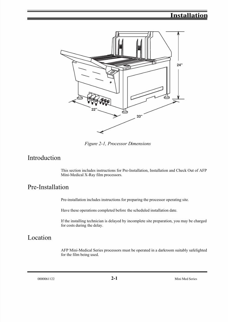
Introduction
This section includes instructions for Pre-Installation, Installation and Check Out of AFPMini-Medical X-Ray film processors.
Pre-Installation
Pre-installation includes instructions for preparing the processor operating site.
Have these operations completed before the scheduled installation date.
If the installing technician is delayed by incomplete site preparation, you may be charged
for costs during the delay.
Location
AFP Mini-Medical Series processors must be operated in a darkroom suitably safelightedfor the film being used.
22"
33"
24"
Figure 2-1, Processor Dimensions
2-1

7/15/2019 Mini-medical 90
http://slidepdf.com/reader/full/mini-medical-90 32/132
Installation
Mini Med Series 0000061122
Dimensions
Mini-Medical Processors occupy 8.0 square feet (22.5" X 24") (57 X 61 cm.) of floor or counter space. The processor should be positioned to allow easy access to all sides of theunit for routine cleaning and preventive maintenance. Drain tubes, leading out of the “front”
of the processor, below the feed tray, must be readily accessible.
Weight
The Mini-Medical Processors weigh approx. 110 lbs. when empty, and approximately 160lbs. when operating.
To support this weight a Processor Stand Assembly is included. Instructions for the assem- bly of this stand can be found in Section 7, Accessories. If the stand is not used, a sturdy,stable and level stand, table or counter must be provided.
Ventilation
WARNING: Some processing chemical fumes may irritate eyes and/or respiratory systemswhen used in a poorly ventilated area. If the processor is to operate in a confined area, provide for at least ten complete changes of air per hour.
Provide adequate ventilation for proper machine operation and operator comfort. The pro-cessor generates a moderate amount of heat when operating and must not be placed in aconfined space, such as a closet.
For best processing results, relative humldity should be between 40% and 60%.
Electrical
Electrical connections must include a ground and conform to local codes. The processor plugs into a standard 120 VAC, 60 Hz, 15 amp., 3 wire outlet. As a factory installed option,Mini-Medical Processors may also be configured for 230 VAC, 50 Hz, operation.
Through-the-Wall
Installation
If your processor is to be Installed through the darkroom wall, refer to Section 7, pages 6and 7.
2-2

7/15/2019 Mini-medical 90
http://slidepdf.com/reader/full/mini-medical-90 33/132
Installation
Mini Med Series0000061122
Pre-Installation,
Continued
Plumbing
WARNING: Obey all instructions of the chemicals manufacturer, and follow all recom-mended safety precautions when handling, using and disposing of chemicals.
The following plumbing requirements are recommended for installation of the Mini- Medi-cal Processors:
1) A flow controlled water source for wash water and for cleaning the processor.
2) A sink, with running tempered water, approximately 12" X 16", for use when cleaningrack modules.
3) A drain suitable for dumping photographic chemical wastes.
Caution: In some locales, environmental regulations may require the capturing and safedisposal of photographic processing wastes other than in the sanitary sewer system.
Check with your local authorities if you are unsure of regulations in your area.
NOTE: The replenisher and drain connections may be run out of the front of the processor in standard configuration or, using the optional Side Drain Kit P/N 9992305002, these linesmay be routed out either the right or left side of the processor. See Section 7, Accessories
for additional details.
"No Plumbing" System Option
The available “No Plumbing” wash water recirculation system, p/n 9992305003 (115 VAC)or p/n 9992305004 (230 VAC), allows the installation of Mini-Medical Processors withoutthe need for an external water supply or drains. If this system is being installed with the processor, refer to the instructions packed with that unit and to Section 7, Accessories, inthis manual.
This completes the pre-installation preparations you are expected to have completed beforethe processor installation date.
2-3

7/15/2019 Mini-medical 90
http://slidepdf.com/reader/full/mini-medical-90 34/132
Installation
Mini Med Series 0000061122
Installation
NOTE: Do not unpack the processor until you have thoroughly inspected the shipping con-tainer for evidence of damage. If there is any damage, contact your shipper immediately for instructions on filing a claim.
Set Up
Unpack the processor and accessory boxes and inspect for any visible shipping damage. Asabove, if any damage is discovered after unpacking, contact the shipper immediately for instructions on filing a claim.
Remove the processor side covers. Remove each of the rack modules and any packingmaterial from the tanks. Inspect each of the racks for loose parts or screws.
Assemble Stand
Following the instructions in Section 7, Accessories, unpack and assemble the included processor stand.
Position Processor
Using two people, carefully position the processor on its stand.
Using a level placed across the walls of the processing tanks, adjust the leveling feet until
the processor is level in both directions.
Connect Replenishment
The processor may be set up to operate its replenishment system in either “Replenish” or “Batch” mode.
In “Replenish” mode the chemicals will be replenished with fresh chemicals from thereplenisher supply and the overflow will be collected for disposal or routed directly to adrain.
In “Batch “ mode the developer and fixer chemicals will be recycled from the replenisher supply to the processing tank and back to the replenisher supply.
2-4

7/15/2019 Mini-medical 90
http://slidepdf.com/reader/full/mini-medical-90 35/132
Installation
Mini Med Series0000061122
Replenish Mode
In “Replenish” mode, fresh replenisher will be pumped from the replenisher supply to the processing tank. Excessive chemicals in the processing tank will flow out of the tank at anoverflow port and into either a container for disposal or an appropriate drain line. In this
manner, constant processing chemical strength may be maintained for longer periods of operation.
To install the processor for “Replenish” mode replenishment operation proceed as follows:(See Figure 2-2)
1) Attach the red developer replenisher pickup tube from the developer replenisher pumpto the developer replenisher reservoir fitting.
2) Route the red developer drain line and red overflow line from the processor to an over-flow container or drain line.
3) Attach the blue fixer replenisher pickup tube from the fixer replenisher pump to the fixer replenishment reservior fitting.
4) Route the blue fixer developer drain line and blue overflow line from the processor to theoverflow container or drain line.
Figure 2-2, Replenish Mode Operation
2-5
DEV
FIX
To Repl. Pump (s)To Drain
7/15/2019 Mini-medical 90
http://slidepdf.com/reader/full/mini-medical-90 36/132
Installation
Mini Med Series 0000061122
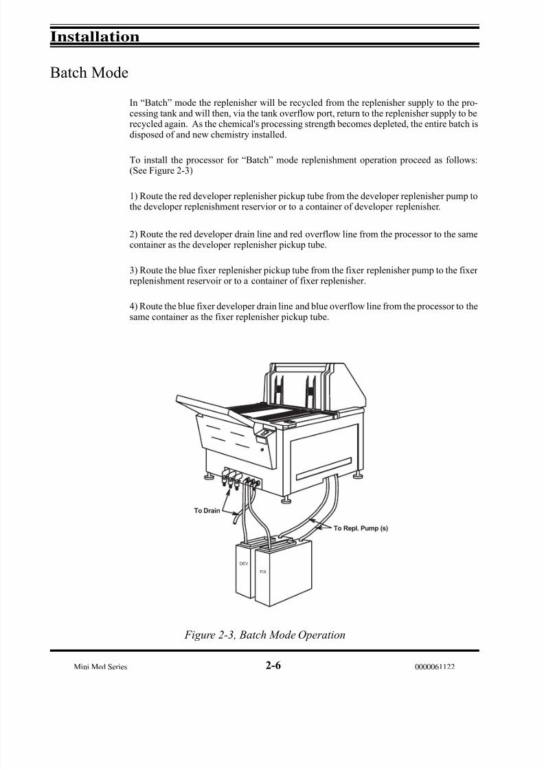
Batch Mode
In “Batch” mode the replenisher will be recycled from the replenisher supply to the pro-cessing tank and will then, via the tank overflow port, return to the replenisher supply to berecycled again. As the chemical's processing strength becomes depleted, the entire batch is
disposed of and new chemistry installed.
To install the processor for “Batch” mode replenishment operation proceed as follows:(See Figure 2-3)
1) Route the red developer replenisher pickup tube from the developer replenisher pump tothe developer replenishment reservior or to a container of developer replenisher.
2) Route the red developer drain line and red overflow line from the processor to the samecontainer as the developer replenisher pickup tube.
3) Route the blue fixer replenisher pickup tube from the fixer replenisher pump to the fixer replenishment reservoir or to a container of fixer replenisher.
4) Route the blue fixer developer drain line and blue overflow line from the processor to thesame container as the fixer replenisher pickup tube.
Figure 2-3, Batch Mode Operation
2-6
FIX
DEV
To Drain
To Repl. Pump (s)

7/15/2019 Mini-medical 90
http://slidepdf.com/reader/full/mini-medical-90 37/132
Installation
Mini Med Series0000061122
Connect Plumbing
Wash water into the processor is controlled by the water solenoid valve. When the proces-sor is in the process mode the solenoid is actuated, allowing wash water to flow into the bottom of the wash tank. Excess water in the wash tank flows over the overflow port and
down the drain.
To connect the wash water proceed as follows: (See Figures 2-2 and 2-3)
1) Route the supplied reinforced water hose from the output of your water panel to thefitting on the wash water solenoid under the right side of the processor.
2) Route the clear wash water drain line and the clear overflow line from the utility sectionof the processor to the building drain or a suitable overflow container.
CAUTION: If you are draining your processor directly into a sanitary sewer, be certain that
such connections are in accordance with local plumbing codes and comply with all localand federal EPA anti-pollution requirements.
DO NOT drain the processor into any drain lines that are made of copper pipe as chemicalreactions will quickly damage the pipes.
"No Plumbing" System Option
The available “No Plumbing” wash water recirculation system, P/N 9992305003 (115 VAC)or 9992305004 (230), allows the installation of any of the Mini-Medical Series processorswithout the need for an external water supply or drains. If this system is being installed
with the processor, refer to the instructions packed with that unit and to Section 7, Accesso-ries, in this manual.
2-7

7/15/2019 Mini-medical 90
http://slidepdf.com/reader/full/mini-medical-90 38/132
Installation
Mini Med Series 0000061122
Control Panel Positioning
In some installations, such as with the right side of the processor against a wall, it may bedifficult for the processor operator to view the LED’s on the Display Panel to the left of thefeed tray.
If this is the case, to make the LED Display Panel more visible, use the following procedureto reverse the positions of the Power Switch/Circuit Breaker and the LED Display Panel.
1) Disconnect the processor power cable from its outlet.
2) Remove the two screws holding the control chassis panel to the front of the processor.Carefully lower the panel until it is supported by its restraining straps.
3) Locate the small screw(s) that holds the LED Display Panel and the Power Switch panelin place. Remove the screws.
4) Carefully unlace the cables for each panel from the retaining clips back as far as thecenter of the loom.
5) Re-install the panels in the desired position,taking care to replace the cables through theretaining clips.
6) Replace the panel securing screws and close the control chassis and secure it with its twoscrews.
7) Return the processor to service.
2-8

7/15/2019 Mini-medical 90
http://slidepdf.com/reader/full/mini-medical-90 39/132
Installation
Mini Med Series0000061122
Processor Checkout
Following set up, inspect the processor as described below to make sure it is ready for use.
WARNING: During this inspection, be sure that the processor power is disconnected at thewall plug.
Inspect and clean the processor tanks, racks and hoses as described below:
1) Open the drain valves on the front of the processor for the developer, fixer and washtanks. Use warm water to rinse each tank clear of dust and debris. Close all drain valves.
2) Shine a light through all hoses to check for foreign matter. To remove anything, discon-nect hose at one end, flush with water, and reconnect.
3) Check, and tighten if necessary, loose hose clamps and/or hardware on the processor.
4) Check that processor is level from front-to-rear and side-to-side. Correct as necessary.
Operational Checkout
Read these instructions completely before starting the processor.
WARNING: Never operate the processor without an electrical ground connection.
1) Close the tank drain valves.
2) If not already done, remove the three racks and set aside.
3) Carefully pour about 1.5 gallons of warm water into each of the solution tanks. Do Notattempt to fill the tank to the overflow.
Attention:When testing or operating the processor with water (as opposed to chemistry), there will bea LOW LEVEL condition in effect which will disable the solution heater. This is due to thefact that water by itself cannot conduct well enough. To prevent this, add 1-2 tablespoonsof salt or a cup of used or fresh developer to the developer tank
4) Install all three racks in their appropriate tanks.
5) With the Power Switch OFF, plug in the power cord.
2-9

7/15/2019 Mini-medical 90
http://slidepdf.com/reader/full/mini-medical-90 40/132
Installation
Mini Med Series 0000061122
Operational Checkout
Continued
Caution: Never attempt to operate the processor without liquid in the tanks.
6) Switch the Power Switch to ON.
7) The transport system will run at Process speed for the duration of one processing cycle,the recirculation pumps will operate and the dryer heaters and fans will be activated.
NOTE: If either of the recirculation pumps do not prime, squeeze the rubber elbow on theinlet side of the pump(s) to purge the air from the line.
8) Inspect all rack modules to verify that they are turning freely.
9) Carefully inspect the underside of the processor for any signs of leakage. Correct if necessary.
10) Operate the Manual Replenishment switch to run the replenishment pumps until thedeveloper and fixer tanks are full of water to the overflow port.
11) Activate the Film Feed switch with a piece of film. The Wait light will turn ON andevery few seconds the replenishment pumps will cycle. Remove the film from the sensor.In a few seconds the Wait light will go out and the beeper will sound.
12) When the Dev Temp lamp turns OFF, check the temperature of the developer with ametal stem or digital thermometer*. If it is not correct for the film you will be using, adjust
the temperature as outlined in Section 5, Service.
*Warning: Do not use a mercury thermometer. If a mercury thermometer breaks, it willcontaminate the machine
2-10

7/15/2019 Mini-medical 90
http://slidepdf.com/reader/full/mini-medical-90 41/132
Installation
Mini Med Series0000061122
Transport Film
Transport several pieces of film of your usual size(s) through the processor. Inspect and, if necessary, correct for the following:
1) Film Feed switch operation. The Wait lamp should stay on continuously until a fewseconds after the trailing edge of the material being processed is clear of the Film Feedswitch.
As the Wait light turns off, an audible beeper will sound indicating it is safe to feed inanother piece of material.
The processor will remain in the process mode for approximately 5 minutes after the filmfeed switch is released.
2) Drift or Skewing. The film should feed through the processor in a straight line. If it
drifts, skews or wrinkles, check the racks for proper seating or loose assembly screws. Becertain you are feeding the film in straight before checking racks.
3) Drying. Be sure the dryer is operating properly. Film processed in water alone may still be slightly tacky or damp when exiting the processor.
Complete Checkout
1) Turn the Power Switch OFF. Unplug the power cord.
2) Drain each of the processing tanks and the replenishment containers for the developer and fix replenishment systems. Close all drain valves.
3) Wipe any excess water from the racks and tanks.
The processor is now ready to be charged with fresh chemistry as instructed in Section 3,OPERATION.
2-11
7/15/2019 Mini-medical 90
http://slidepdf.com/reader/full/mini-medical-90 42/132
Installation
Mini Med Series 0000061122
Processor Set Up
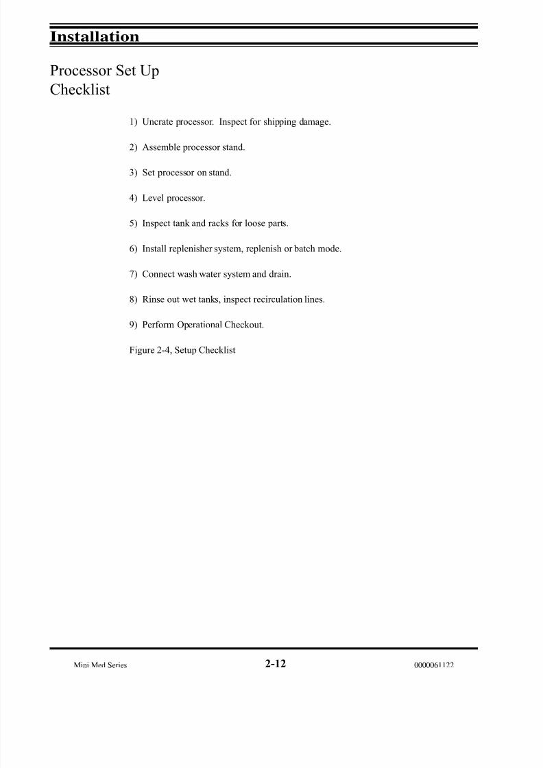
Checklist
1) Uncrate processor. Inspect for shipping damage.
2) Assemble processor stand.
3) Set processor on stand.
4) Level processor.
5) Inspect tank and racks for loose parts.
6) Install replenisher system, replenish or batch mode.
7) Connect wash water system and drain.
8) Rinse out wet tanks, inspect recirculation lines.
9) Perform Operational Checkout.
Figure 2-4, Setup Checklist
2-12
7/15/2019 Mini-medical 90
http://slidepdf.com/reader/full/mini-medical-90 43/132
Installation
Mini Med Series0000061122
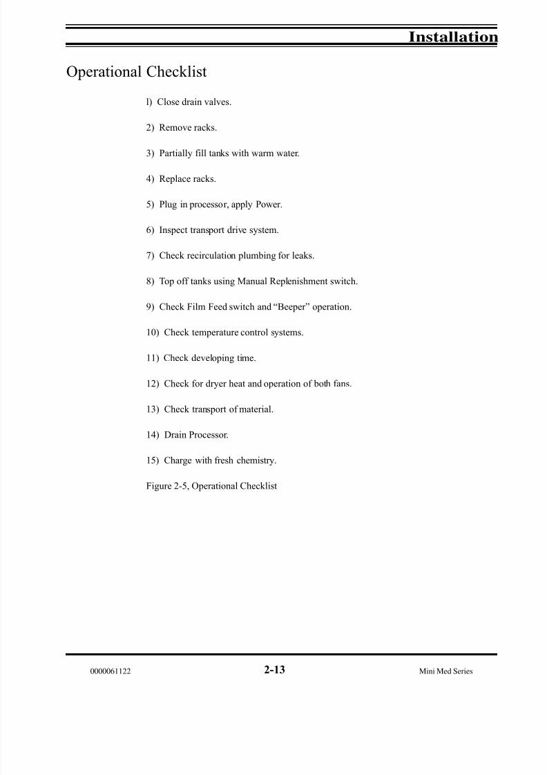
Operational Checklist
l) Close drain valves.
2) Remove racks.
3) Partially fill tanks with warm water.
4) Replace racks.
5) Plug in processor, apply Power.
6) Inspect transport drive system.
7) Check recirculation plumbing for leaks.
8) Top off tanks using Manual Replenishment switch.
9) Check Film Feed switch and “Beeper” operation.
10) Check temperature control systems.
11) Check developing time.
12) Check for dryer heat and operation of both fans.
13) Check transport of material.
14) Drain Processor.
15) Charge with fresh chemistry.
Figure 2-5, Operational Checklist
2-13

7/15/2019 Mini-medical 90
http://slidepdf.com/reader/full/mini-medical-90 44/132
Installation
Mini Med Series 0000061122
Notes:
2-14
7/15/2019 Mini-medical 90
http://slidepdf.com/reader/full/mini-medical-90 45/132
AFP Mini-Medical
X-Ray Film Processors
- General Index -
Section 0 - Safety Information
Section 1 - Introduction
Section 2 - Installation
Section 3 - Operation
Section 4 - Maintenance
Section 5 - Service
Section 6 - Parts
Section 7 - Accessories
0000061122
Section 3 Operation

7/15/2019 Mini-medical 90
http://slidepdf.com/reader/full/mini-medical-90 46/132

7/15/2019 Mini-medical 90
http://slidepdf.com/reader/full/mini-medical-90 47/132
Operation
Mini Med Series0000061122
NOTE: For operator convenience, the
LED Display Panel and the Power Switch
Panel may be switched, right to left,
during installation of the processor.
See Page 2-8 for details.
Figure 3-1, User Controls
Controls and Indicators
All of the user controls and indicators for operation of Mini-Medical Processors arelocated on the front of the processor. These controls are described below and on thefollowing page.
User Controls
1. Power Switch
OFF All power to processor is OFF.ON Processor is ON, (runs one approximate 5 minute process cycle initially),
then reverts to standby mode. Circulation pumps, developer heater and air circulation fan are ON. Transport, replenishment system and dryer willoperate when Film Feed switch is activated. Power On lamp will light.
CENTER This switch also serves as the circuit breaker for the processor. If tripped tothe center position reset to OFF, then turn ON. If the switch trips again, the processor probably needs a service call. Do not use the processor if it tripsoff repeatedly.
1
2
4
8
7
3
9
6
5
3-1
7/15/2019 Mini-medical 90
http://slidepdf.com/reader/full/mini-medical-90 48/132
Operation
Mini Med Series 0000061122
User Controls,
Continued
2. Manual Replenishment Switch
Provides for manual operation of replenishment pumps. Use to “top off” tanks or toturn over chemistry when activity levels have dropped.
3. Power ON LED
Lights when Power Switch is ON.
4. Dev Temp LED
Lights when developer heater is ON. Wait for light to cycle OFF before first use each
day.
5. Wait LED
Illuminates when Film Feed switch is activated. To prevent fogging of film, wait untillamp goes OFF or beeper sounds before opening feed tray.
6. Low Dev LED
Lamp ON indicates that developer is too low for safe operation. To prevent damage tothe processor, the developer heat function is turned OFF when a low level condition
exists.
7 Drain Valves
Drains the Developer, Fixer, Wash tank and recirculation pumps.
8. Overflow Lines
Drain lines from developer, fix & wash overflow ports.
9 Top Cover Interlock Switch
To prevent accidental injury from moving parts, a safety switch is interlocked with the processor’s top cover. If the top cover is removed, the processor automatically shutsdown. This interlock may be overridden for service use only by using the service holddown tool included in the Maintenance Kit provided with each unit.
Caution: DO NOT attempt to process film in this unit when the interlock is overridden.
3-2
7/15/2019 Mini-medical 90
http://slidepdf.com/reader/full/mini-medical-90 49/132
Operation
Mini Med Series0000061122
Loading Chemicals
Always begin with a clean processor. The processor should have been cleaned in thenormal course of installation or maintenance.
With the developer and/or fixer tank cleaned and drained, add processing chemicals asdescribed below:
WARNING: Read and heed safety precautions given by your chemical manufacturer in mixing, using and disposing of processing solutions.
To prevent chemical splashing and the risk of contamination follow these instructionscarefully.
1) Close the tank drain valves at the front of the processor.
2) If not already done, remove the three racks and set aside.
3) Cover the developer tank with a sheet of newspaper to protect it from accidentalsplashes of fixer.
4) Carefully pour about 1.5 gallons of fixer working solution into the fix tank. Do Notattempt to fill the tank to the overflow.
5) Cover the fixer tank with a sheet of newspaper to protect it from accidental splashesof developer.
6) Carefully pour about 1.5 gallons of developer working solution into the developer tank. Do Not attempt to fill the tank to the overflow.
7) Carefully pour about 1.5 gallons of warm water into the wash tank. Do Not attemptto fill the tank to the overflow.
8) Replace the racks. Lower them into the tanks slowly to prevent splashing. Check for correct seating on the locating pins and driveshaft.
9) Attach the replenisher hoses to the fittings on the replenisher supply containers.
10) Turn the Power Switch-ON. Operate the Manual Replenishment switch to run thereplenishment pumps until the developer and fixer are seen in the overflow drain tubes.
3-3

7/15/2019 Mini-medical 90
http://slidepdf.com/reader/full/mini-medical-90 50/132
Operation
Mini Med Series 0000061122
Daily Start Up
The daily start up procedure is as follows:
Processor ON,
Fill Wash Tank
1) Close the wash tank drain valve.
2) Switch the Power Switch to the ON position. The processor will start in the processmode and run for approximately 5 minutes, filling the wash tank. If, at the end of the process cycle, the wash water has not reached the overflow port, trip the Manual Re- plenishment switch to initiate another processing cycle.
3) Allow the developer to warm up to operating temperature (Dev Temp light willcycle OFF). Check for leaks around all hose fittings.
Caution: Always inspect to see that all drain tubes are properly positioned and drainingcorrectly. All drain tubes must be routed in a continuously downward direction, with-out dips or loops that can cause airlocks.
Caution: A kink or twist in a drain tube can cause a serious chemical or water spill inthe processor.
Check Developer
and Fixer Levels
If not previously done, check the developer and fix tanks to see that they contain ad-equate solution. Prepare fresh replenisher if necessary and using the Manual Replen-
ishment switch, top off each tank with chemistry to the overflow port.
Check Drive
With the Power Switch in the ON position, check all turning drive gears to see that theymesh properly and turn without binding. Make sure the transport rollers are turningfreely, without interference or binding.
3-4
7/15/2019 Mini-medical 90
http://slidepdf.com/reader/full/mini-medical-90 51/132
Operation
Mini Med Series0000061122
Processing Film
Feed film into the processor. As it actuates the feed sensor, the WAIT lamp on thecontrol panel will light.
If you turn the room lights on after feeding film, to prevent fogging the end of your film, do not open the daylight cover until after the Wait light goes out or the beeper sounds.
After the processor completes its processing cycle it will automatically return to Stand-By mode.
Shutdown and Daily Cleaning
Basic care of the processor goes hand-in-hand with its operation. Following each day’swork, allow 15 minutes to clean the processor as described below.
Drain Wash Tank
Open the wash tank drain valve and allow the wash water to drain. Rinse out the washtank with fresh warm water, then close the drain valve.
Clean Top Cover,
Guides & Rollers
Using a separate wet cloth for developer and fixer, wipe the exposed rollers on eachrack.
Caution: Do not use the same cloth for fixer and developer racks. Fixer may contami-nate the developer.
Wipe off Processor
Thoroughly wipe the inside and outside surfaces of the top cover and side panels witha damp cloth. Replace the top cover, leaving a slight opening over the drive shaft to prevent condensation of chemistry vapors.
3-5

7/15/2019 Mini-medical 90
http://slidepdf.com/reader/full/mini-medical-90 52/132
Operation
Mini Med Series 0000061122
Quality Control
A good quality control program is essential to the production of quality radiographs.
It is recommended that a quality control program for your processor be established and
maintained to assure the quality of your output.
Following are some suggestions for those areas that should be monitored. Contact your film and chemistry technical representative for additional information and assistance.
Developer
Developer activity can be monitored by use of pre-exposed control strips, availablefrom your film supplier, or by careful monitoring of your production work.
Fixer
Exhausted fixer will usually result in dark streaks in your film’s emulsion that mayappear immediately after processing or may not appear until hours or even days after processing.
Exhausted fixer can also contribute to transport problems such as jams and will fre-quently prevent proper drying from taking place, resulting in sticky film surfaces.
The general health of your fixer can be determined by monitoring the pH of the chem-istry.
When pH is too high, films may jam in the wash tank and the dryer. To determine pH,immerse pH test strips, available from your dealer, in the fixer and read its pH value
from the resultant color change on the strip. If the pH rises toward the chemicalmanufacturer’s recommended upper limit, dump the old fixer and replace with freshchemicals.
NOTE: Only terminal-type silver recovery systems are recommended for use with this processor. Do not try to re-use fixer after silver has been removed.
3-6
7/15/2019 Mini-medical 90
http://slidepdf.com/reader/full/mini-medical-90 53/132
Operation
Mini Med Series0000061122
Replenishment
Replenishment in Mini-Medical Processors consists of “topping” off the developer andfixer tanks with fresh working solution at the start of each shift and automatic replen-ishment by the replenishment system.
Automatic replenishment is accomplished by the film tripping one or both of the FilmFeed Switches which, in turn, actuates the electronic replenishment circuitry. Depend-ing on technician set adjustments, the developer and fixer pumps will cycle on and off during film feeding to replenish the working solution in the developer and fixer tanks.
Manual Replenishment may be required for one of three reasons. They are:
1) To top off the tanks at start-up.
2) To restore chemical strength after several days of shut down.
3) To compensate for a basic under-replenishment condition. (See NOTE below)
NOTE: Chemistry requirements vary by the type of work and average size of films youare processing. If you find that you must frequently use the Manual Replenishmentswitch to add fresh chemistry, it is recommended that you have your technician adjustthe replenishment control circuits as required to allow for adequate automatic replen-ishment.
3-7

7/15/2019 Mini-medical 90
http://slidepdf.com/reader/full/mini-medical-90 54/132
Operation
Mini Med Series 0000061122
Checklists for Daily Use
Startup
1. Check solution levels.a) Top off processing tanks and fill wash tank.
2. Power Switch to ON, check drive gears for meshing;allow 15-30 minutes warm up.
3. Clean feed tray, receiving bin.
4. Check developer activity, fixer pH.
Operation
1. Feed material, trip Film Feed switch to start processing cycle.
2. Wait until Wait light goes out or beeper sounds before opening film feed tray.
Shutdown and Daily Cleaning
1. Switch off power.
2. Drain and rinse wash tank, close valve.
3. Clean:a) roller surfaces, rack and tank area b) splashes from inside top cover.
4. Wipe outside surfaces of the processor, inside surfaces of feed tray & cover boxand both side panels.
5. Leave top cover slightly open to prevent condensation.
NOTE: Duplicate these checklists and post them near the processor.
3-8

7/15/2019 Mini-medical 90
http://slidepdf.com/reader/full/mini-medical-90 55/132
AFP Mini-Medical
X-Ray Film Processors
- General Index -
Section 0 - Safety Information
Section 1 - Introduction
Section 2 - Installation
Section 3 - Operation
Section 4 - Maintenance
Section 5 - Service
Section 6 - Parts
Section 7 - Accessories
0000061122
Section 4 Maintenance

7/15/2019 Mini-medical 90
http://slidepdf.com/reader/full/mini-medical-90 56/132
7/15/2019 Mini-medical 90
http://slidepdf.com/reader/full/mini-medical-90 57/132
Maintenance
Mini Med Series0000061122
Maintenance Program
Maintenance of M in i-M edical Processors consists of cleaning and adjustment operations,routinely performed, to keep the processor operating correctly. Early in the life of your processor set up a maintenance program, with specific people responsible for performingeach maintenance task.
Maintenance Records
Good preventive maintenance is essential to assure a long and trouble free life for your processor. Keeping on-going records of maintenance will help assure that the work is performed when scheduled.
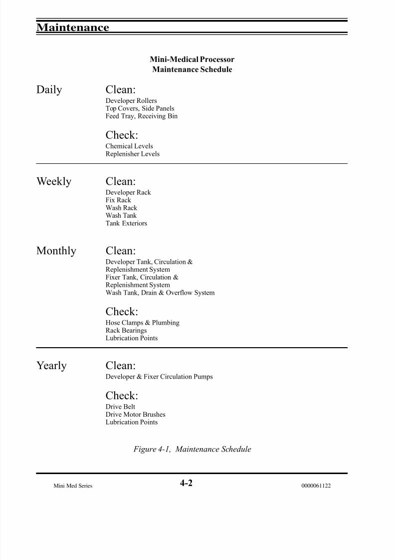
Figure 4-1 is a Maintenance Schedule that lists tasks to be performed at prescribed mainte-
nance intervals.
Figure 4-2 is a Maintenance Log for keeping monthly records of maintenance performed.Make additional copies and post near the processor.
Cleaning
Cleaning is the most important form of maintenance. If chemicals are allowed to accumu-late on processor parts they can cause corrosion or other damage which may seriouslyaffect production and output quality.
Perform daily cleaning, as outlined on the Maintenance Schedule, Figure 4-1, as part of the
shutdown procedure.
Weekly cleaning, described below, should take about thirty minutes following the last shut-down and daily cleaning.
Do not replace items removed for daily cleaning until after weekly cleanup has been com- pleted.
Caution: Never use harsh abrasive mater ial to clean racks or processing tanks. Never
use scrub pads such as " Scotchbri te" on roll ers.
4-1
7/15/2019 Mini-medical 90
http://slidepdf.com/reader/full/mini-medical-90 58/132
Maintenance
Mini Med Series 0000061122
Mini-Medical Processor
Maintenance Schedule
Daily Clean:Developer RollersTop Covers, Side PanelsFeed Tray, Receiving Bin
Check:Chemical LevelsReplenisher Levels
Weekly Clean:Developer Rack Fix Rack Wash Rack Wash Tank Tank Exteriors
Monthly Clean:Developer Tank, Circulation &Replenishment SystemFixer Tank, Circulation &Replenishment System
Wash Tank, Drain & Overflow System
Check:Hose Clamps & PlumbingRack BearingsLubrication Points
Yearly Clean:Developer & Fixer Circulation Pumps
Check:Drive BeltDrive Motor BrushesLubrication Points
Figure 4-1, Maintenance Schedule
4-2

7/15/2019 Mini-medical 90
http://slidepdf.com/reader/full/mini-medical-90 59/132
Maintenance
Mini Med Series0000061122
Note: If Processor is run 80 hours or more a week, perform maintenance twice as often. 1. Duplicate this copy to provide a supply of log sheets.
2. Perform operations as instructed in User's Manual.
3. List operating hours at each operation and initial.
4. Retain completed log sheets for continuing history.
* Where applicable
Figure 4-2, Maintenance Log
Mini-Medical Processor
Maintenance Log
4-3
1
2
3
4
5
10
9
8
76
16
17
1819
20
15
14
13
12
11
21
22
23
24
29
28
27
26
25
3130
C L E A N D E
V. R O L L E R S
I N I T I A L U P
O N C O M
P L E T I O N
C L E A
N T O
P C O V E R S
C L E A N S Q U E
E G E E
R O L L E R S
C L E A N F E E D
T R A
Y
C L E A N R E
C E I V I N G B I N
C H E C
K C H E M
I C A L
L E V E L
S
C H A N
G E W A S H W A T E R
C L E A
N D E
V. T R A
N S P O
R T
C L E A
N F I X T R
A N S P O R T
C L E A N W A S H T R
A N S P O R T
C L E A
N W A S H T A N K
C L E A N T A N K
E X T E R I O R S
C H A N
G E D E V E L
O P E R
C H A N
G E F I X E R
DAILYRECORDMONTH WEEKLY
CLEAN DEVELOPER SYSTEM
CLEAN FIXER SYSTEM
CLEAN WASH SYSTEM
CHECK HOSE CLAMPS
CHECK LUBRICATION DIAGRAM
NOTES
CHECK LUBRICATION DIAGRAM
CHECK MOTOR BRUSHES
CHECK DRIVE BELTCLEAN FIX & WASH PUMPS
DRIVE SHAFT GEARS (MONTHLY)
DRYER TRANSPORT GEARS (MONTHLY)
DRIVE SHAFT BRGS (MONTHLY)
DATEHRS OPERATION INITMONTHLY MAINTENANCE
YEARLY MAINTENANCE
LUBRICATION
DAY
*

7/15/2019 Mini-medical 90
http://slidepdf.com/reader/full/mini-medical-90 60/132
Maintenance
Mini Med Series 0000061122
Weekly Cleaning
1) Remove the developer, fixer and wash racks. To prevent chemical contamination, wash
off each rack separately with clean, lint-free cloths and warm water. Clean each roller over its entire surface. Use isopropyl alcohol if necessary to remove traces of adhesives.
NOTE: Soft scrub pads, such as nylon net over sponge, work well on rollers. Metallic, or non-metallic, scrub pads such as "Scotchbrite", must not be used on rollers as they willdamage the roller surface.
2) Inspect each rack thoroughly. Verify that the rollers turn freely and that all guides and baffles are properly in place. Carefully set each rack aside to drain and dry while you arecleaning the rest of the processor.
3) Clean the outside surfaces of the processing tank, using warm water with a sponge or
non-metallic scrub pad.
Caution: Never use steel wool on any part of the processor as its residue may causerust to form on the metallic parts of the processor.
4) Clean the dryer rollers and rack parts with a damp cloth and wipe dry.
5) Replace all removed racks and other parts.
4-4

7/15/2019 Mini-medical 90
http://slidepdf.com/reader/full/mini-medical-90 61/132
Maintenance
Mini Med Series0000061122
Monthly Cleaning
As film is processed, by-products are released into the developer, fix and wash systems.These must be removed by regular cleaning. Every month, schedule two hours of processor downtime to thoroughly clean the developer, fixer and wash systems.
NOTE: This cleaning will replace the scheduled Weekly Cleaning due on the same date.
1) Open the drain valves, drain and dispose of the used developer, fixer and wash water.Allow the tanks and recirculation systems to drain completely.
Caution: When filling or rinsing the processor tanks, use water no hotter than 120degrees F (54 degrees C).
2) Bring a small bucket or container of warm water to the processor and place the red and
blue intake hoses going to the replenisher pumps into the container. Press and hold themanual replenishment switch (located on the upper right hand front corner of the machine)until the water comes out clear. Remove the intake hoses from the container and press andhold the switch again until the pumps and lines are purged. Replace the hoses to their original chemistry containers.
3) Rinse out each tank and then close the drain valves and fill the wash tank with warmwater.
4) Systems Cleaning.
The use of Developer Systems and Fixer Systems Cleaners are recommended for cleaning
the developer and fixer system. Carefully follow the manufacturer’s instructions and pre-cautions. Dissolve any powdered chemicals in water before adding to the tank. Be sure toaccomplish the neutralizing and rinsing steps recommended by the systems cleaner manu-facturer.
WARNING: Beware of all rotating gears, shafts and drive belts when operating theprocessor with its access panels removed.
5) After the developer and fixer systems are thoroughly cleaned, neutralized and rinsed, filleach tank with fresh warm water and install the racks. Switch processor ON and allow thetransport and recirculation systems to run for about 15 minutes as a final rinse.
(Continued on Next Page)
4-5
7/15/2019 Mini-medical 90
http://slidepdf.com/reader/full/mini-medical-90 62/132
Maintenance
Mini Med Series 0000061122
Monthly Cleaning,
Continued
Systems cleaning will remove most, if not all, of the chemical residue from the transportracks. For additional cleaning and inspection, proceed as outlined below:
A) Remove the rack from the tank.
B) Clean the developer and fix racks without disassembling them.
C) Appropriate Systems Cleaner may be used to remove stubborn deposits. Never use“Scotchbrite” type pads on roller surfaces. Rinse the rack thoroughly after it has beencleaned.
D) Inspect all rack end plates for wear. Be sure the rollers turn freely.
Bearing wear differs according to the solution in which the rack is used. Since bearings
tend to wear more quickly in the fixer solution, the fixer rack end plates should be checkedmore frequently for wear.
Clean Tanks
Inspect the empty processing tank for foreign matter and, if necessary, use a soft scrub pador brush and warm water to clean the tank interior. Flush the tank with warm water anddrain.
Inspect Processor
Check the hose clamps on the developer, fixer and wash pumps and the base of each pumpfor leaks. Secure as necessary.
Caution: Do not over-tighten clamps. This can cause leakage or damage to the pumpheads.
(Continued on Next Page)
4-6

7/15/2019 Mini-medical 90
http://slidepdf.com/reader/full/mini-medical-90 63/132
Maintenance
Mini Med Series0000061122
Prepare Fresh Chemicals
When the developer and fixer systems are clean, prepare and load fresh chemicals in accor-dance with instructions in Section 3, Operation, and the manufacturer’s instructions and precautions.
Monthly Lubrication
Refer to Figure 4-2, Maintenance Log and Figure 4-3, Lubrication Points and lubricate asindicated. Be sure to clean off all old lubricants and any excessive new lubricants.
Annual Maintenance
Once a year, following a routine monthly cleaning, perform the following tasks on the
processor:
1) Inspect the drive gears on each rack and replace any gears that are excessively worn or damaged.
2) Refer to Service Procedure 5-1. Inspect, and adjust or replace if necessary, the maindrive belt.
3) Refer to Service Procedure 5-2. Inspect and clean the fixer circulation pump. Thedeveloper pump is usually cleaned adequately by systems cleaning and does not requireadditional servicing.
4) Refer to Service Procedure 5-3. Inspect and clean the developer and fixer replenishment pumps.
5) Refer to Figure 4-2, Maintenance Log and Figure 4-3, Lubrication Points and lubricateas indicated.
Be sure to clean off all old lubricants and any excessive new lubricants.
4-7

7/15/2019 Mini-medical 90
http://slidepdf.com/reader/full/mini-medical-90 64/132
Maintenance
Mini Med Series 0000061122
Removing Old Lubricants
Dust and dirt, mixed with oil or grease, can prevent fresh lubricants from reaching thesurfaces that need it most.
Before applying new lubricant, clean accumulations of grease from the gears. Hold a ragalongside each gear, and brush debris from the gear onto the rag. Clean as much of everydrive gear as possible, then run the processor transport system very briefly, and clean againuntil all portions of the gears have been exposed for cleaning.
After the drive gears have been cleaned, lubricate them as indicated in Figure 4-3.
Lubrication Points
Location Interval Lubricant
Drive Shaft Bearings & Worm Gears Monthly Oil/Teflon Oiler Dryer Gears Monthly Oil/Teflon Oiler
NOTE:DO NOT lubricate any gears or other parts that come in contact with solutions or water.
Figure 4-3, Lubrication Points
4-8
7/15/2019 Mini-medical 90
http://slidepdf.com/reader/full/mini-medical-90 65/132
AFP Mini-Medical
X-Ray Film Processors
- General Index -
Section 0 - Safety Information
Section 1 - Introduction
Section 2 - Installation
Section 3 - Operation
Section 4 - Maintenance
Section 5 - Service
Section 6 - Parts
Section 7 - Accessories
0000061122
Section 5 Service

7/15/2019 Mini-medical 90
http://slidepdf.com/reader/full/mini-medical-90 66/132
7/15/2019 Mini-medical 90
http://slidepdf.com/reader/full/mini-medical-90 67/132
Service
Mini Med Series0000061122
Content
This section contains information on trouble-shooting and repairing AFP Mini-MedicalSeries Processors.
Always consult the Troubleshooting Chart before attempting service or repair, or beforecalling a service representative.
Even if you do not plan to service the processor yourself, the chart will help you explainthe problem to a service representative.
WARNING: Be extremely careful when tr ouble-shooting or servicing the processor
with the power on. Dangerous, potenti all y lethal, electr ical voltages are present at
several points.
Following the Troubleshooting Charts are instructions for performing adjustment andrepair procedures that may be required to keep the processor functioning.
Also in this section is a description of the control electronics in the processor, withapplicable schematics and a wiring diagram. These will enable users who are trainedand equipped for electronics trouble-shooting to trace failures in the electronics.
NOTE: The circuit cards in this processor are not considered field repairable and in theevent of a component failure, should be replaced.
Attempting to repair them could invalidate any remaining warranty, or may cancel theexchange credit value that some cards may have.
Troubleshooting
The Troubleshooting Charts are divided into three columns. To use either chart, findon the left, under symptom, a problem that sounds like yours. In the middle column, indiminishing order of likelihood, are the Probable Causes for such a symptom. Theright-hand column, Remedy, provides corrective action(s) for each probable cause.
(Continued on Next Page)
5-1

7/15/2019 Mini-medical 90
http://slidepdf.com/reader/full/mini-medical-90 68/132
Service
Mini Med Series 0000061122
Service Procedures
Following the Troubleshooting Charts are service procedures for repair and maintenanceof the processor.
Below is an index to those procedures:
Procedure Title
5-1 Inspecting, Adjusting & Changing the Main Drive Belt
5-lA Film Sensors and Adjustments
5-2 Servicing Circulation Pumps
5-3 Servicing Replenisher Pumps
5-4 Calibration Procedures
5-5 Circuit Descriptions
Schematics
The following schematics are included for servicing AFP Mini Medical Series X-Rayfilm processors.
Figure 5-1 AC Interconnect Diagram
Figure 5-2 Dryer Rack Wiring Diagram
Figure 5-3 AC Interface Board
Figure 5-4 AC Interface Board Schematic
Figure 5-5 Logic Board Schematic
Figure 5-6 Logic Board Layout
Figure 5-7 Ready Tone Generator Schematic
5-2

7/15/2019 Mini-medical 90
http://slidepdf.com/reader/full/mini-medical-90 69/132
Service
Mini Med Series0000061122
Troubleshooting
Processor Problems
Symptom Probable Cause Remedy
5-3
1. Developing time not
constant.
2. Solution temperature
too high.
3. Solution temperature
too low.
4. Dryer temperature
too low.
5. Dryer temperature
too high.
6. Film jams.
A. Excessive load on drive motor.
B. Solution levels low.
A. Temperature control setting
moved.
B. Shorted heater triac.
C. Defective temperature sensor.
(Open)
D. Logic failure.
A. Heater failed.
B. Heater triac failed. (Open)
C. Temperature control setting
moved.
D. Shorted temperature sensor.
E. Logic failure.
A. Failed heating element.
B. Open overtemp switch on
dryer.
C. Shorted temperature sensor.
A. Open temperature sensor.
B. Blower failure.
C. Logic failure.
A. Film not fed in squarely.
B. Improper fixing, fixer too old,
pH too high, or improperly
mixed fixer or fixer replenisher.
A. Check that racks are
seated and turn freely.
B. Add chemicals as
required.
A. Restore correct setting.
B. Replace heater triac.
C. Replace temperature
sensor.
D. Replace logic board.
A. Replace heater.
B. Replace heater triac.
C. Restore correct setting.
D. Replace sensor.
E. Replace logic board.
A. Replace element.
B. Will reset when cool.
Inspect for cause; fan not
running, dirt build-up, etc.
C. Replace sensor
A. Replace sensor.
B. Replace blower.
C. Replace logic board.
A. Feed film in carefully,
leading edge parallel to
rollers.
B. Check pH. If pH is above
5.0, dump and mix fresh.
Follow the mfg's
instructions exactly.
7/15/2019 Mini-medical 90
http://slidepdf.com/reader/full/mini-medical-90 70/132
Service
Mini Med Series 0000061122
Troubleshooting
Processor Problems,
Continued
Symptom Probable Cause Remedy
5-4
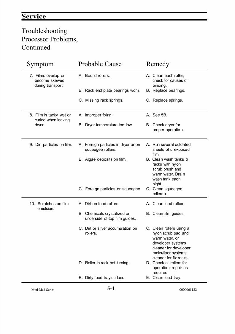
7. Films overlap or
become skewed
during transport.
8. Film is tacky, wet or curled when leaving
dryer.
9. Dirt particles on film.
10. Scratches on film
emulsion.
A. Bound rollers.
B. Rack end plate bearings worn.
C. Missing rack springs.
A. Improper fixing.
B. Dryer temperature too low.
A. Foreign particles in dryer or on
squeegee rollers.
B. Algae deposits on film.
C. Foreign particles on squeegee
A. Dirt on feed rollers
B. Chemicals crystallized on
underside of top film guides.
C. Dirt or silver accumulation on
rollers.
D. Roller in rack not turning.
E. Dirty feed tray surface.
A. Clean each roller;
check for causes of
binding.
B. Replace bearings.
C. Replace springs.
A. See 5B.
B. Check dryer for
proper operation.
A. Run several outdated
sheets of unexposed
film.
B. Clean wash tanks &
racks with nylon
scrub brush and
warm water. Drainwash tank each
night.
C. Clean squeegee
roller(s).
A. Clean feed rollers.
B. Clean film guides.
C. Clean rollers using a
nylon scrub pad andwarm water, or
developer systems
cleaner for developer
racks/fixer systems
cleaner for fix racks.
D. Check all rollers for
operation; repair as
required.
E. Clean feed tray.

7/15/2019 Mini-medical 90
http://slidepdf.com/reader/full/mini-medical-90 71/132
Service
Mini Med Series0000061122
Troubleshooting
Processor Problems,
Continued
Symptom Probable Cause Remedy
Note: The interupter switch may be bypassed for troubleshooting purposes only byeither utilizing the hold down tool (P/N 0000021801) to keep the switch activated.Jumping the pins on J-14 on the logic board is an alternate method.
5-5
11. Increase in image
12. Decrease in image
density.
13. Over replenishing.
14. No functions
A. Film is over exposed.
B. Developer temperature too high.
C. Excessive developing time due
to mechanical binding.
D. New developer improperly mixed.
.
A. Film is under exposed.
B. Developer under replenished
or exhausted.
C. Developer temperature too low.
D. Developer time too short.
E. New developer improperly
mixed.
A. Shorted film presence switch.
B. Shorted manual replenishment
switch.
C. Pendulum magnet weak or
stuck in the up position.
D. Logic failure
A. Interupter switch not activated.
B. Interupter switch defective.
A. Coordinate exposure
with developing time.
B. Have service technician
troubleshoot developer
temperature.
C. See symptom 1.
D. Dump and mix fresh,
following mfg'sinstructions exactly.
A. Coordinate exposure
B. Change developer.
Check replenishment
rates.
C. See Symptom 3.
D. Check developer for
low level.E. Dump developer and
mix fresh.
A. Replace switch.
B. Replace switch.
C. Clean or replace
pendulum.
D. Replace logic board.
A. Put top cover in place.
B. Replace switch.
7/15/2019 Mini-medical 90
http://slidepdf.com/reader/full/mini-medical-90 72/132
Service
Mini Med Series 0000061122
Service Procedure 5-1
Inspecting, Adjusting & Changing
the Main Drive Belt
The main drive belt requires only minimal maintenance and normally lasts many yearswith normal use.
Inspection
The belt should be inspected yearly. Replacement is indicated if any of the followingconditions are found:
1) Excessive slack that cannot be corrected.2) Frayed or badly worn edges.3) Missing or damaged drive lugs on the belt surface.
AdjustmentCAUTION: Overtightening the belt will cause the belt to jump on the wormshaftpulley and will cause the saddle bearing nearest the pulley to become excessivelyhot.
Adjusting slots to tension the drive belt are provided in the motor mounting plate.Adjust in the following manner:
1) Unplug the processor from its power outlet.2) Loosen the four motor mounting plate screws. These are accessible on the back
of the processor, below the dryer.3) Slide the motor until the belt has approximately 1/2" of play. With no racks in
place, you should be able to rotate the driveshaft with your fingers approxi-mately 1/8" back and forth.
4) Tighten the four screws.5) If most of the slack cannot be removed, the belt is worn excessively and should
be replaced.
Replacement
The following procedure is to be followed when replacing a worn drive belt:
1) Unplug the processor from its power outlet.2) Remove all four racks (dev, fix, wash & dryer) and carefully set aside.3) Loosen the four drive motor mounting plate attaching screws on the rear of the
processor. Move the motor to remove the drive belt.4) Remove the cotter pin holding the drive belt pulley to the driveshaft.5) Slide the driveshaft pulley forward far enough to allow removal of the belt
around the end of the driveshaft.6) Install the new belt in the reverse order.7) Adjust the new belt as described above.
5-6
7/15/2019 Mini-medical 90
http://slidepdf.com/reader/full/mini-medical-90 73/132
Service
Mini Med Series0000061122
Service Procedure 5-lAFilm Sensors and Adjustments
Mini-Medical processors up to and including S/N MM1899-90
Film sensing for Mini-Medical processors up to and including S/N MM1899-90 wasaccomplished by mounting a magnetic reed switch assembly in the center of the upper edge inside the molded feed tray adapter.
When film is not present in the feed tray, a magnetic pendulum assembly is in close proximity to the reed switch, wired in a normally closed configuration. This means thatit is held open by the magnet when film is not present. When film is inserted in the feedslot, the pendulum is pushed upward and away from the reed switch, causing it to close.This puts a short across pins 1 and 2 of J13 on the ready tone generator board, puttingthe machine into the process mode. When the pendulum returns to its position of rest,the reed switch opens initiating timers for the beeper, wait light and cycle time.Approximately 8 seconds after the reed switch opens the beeper should sound and the
wait light should go out.
If a machine fails to go into standby, the magnet may have weakened, or the switch may be stuck in the closed position; or the switch may be adjusted too far away from the pendulum to activate the switch.
First, unplug J13 from the ready tone generator board. If the wait light goes out and the beeper sounds after approximately 8 seconds, the switch is either shorted or the magnetis failing to activate it.
To test the switch, first remove the switch from the machine. Use a magnet to activatethe switch while looking across the switch with a meter set on Ohms. If the switch failsto open it should be replaced. If it does open, try adjusting it as close to the pendulum
assembly as possible. If this doesn’t help replace the pendulum assy.
If the machine remains in the process mode after unplugging the switch from the J13connector on the ready tone board, unplug the ready tone board from J13 on the mainlogic board. If the wait light goes out after approximately 8 seconds, the ready tonegenerator board should be replaced. If unplugging the ready tone board does not clear up the problem, a rare problem on the logic board itself is indicated.
Mini-Medical processors S/N MM1900-90 and above
Starting with S/N MM-1900-90, Mini-Medical processors feature a new style of filmsensing. This is in the form of two hall-effect magnetic digital sensors (P/N 21878)
located approximately three inches in from the inner right and left sides of the feed tray.There are now two magnetic pendulum assemblies (P/N 21893), located above the feedtray, that are used in conjunction with these sensors.
Activation of either switch will put the machine into the process mode. The purpose of the dual switch arrangement is to accommodate smaller size films. The feed tray assemblyhas changed to P/N 21876. (The part numbers given above are for 1 each of the parts.)
5-7

7/15/2019 Mini-medical 90
http://slidepdf.com/reader/full/mini-medical-90 74/132
Service
Mini Med Series 0000061122
Service Procedure 5-1 AFilm Sensors/Adjustments, Cont'd
Film sensor location configuration (See figure 5-1)
Film Sensor Adjustment: These sensors are adjusted at the factory and normally donot need adjustment. However, should adjustment be required, follow this procedure:
1) Loosen the screw on each small bracket securing the sensors to the molded feed trayadapter; the sensors may be moved up or down.
2) Locate each sensor upward close enough to the magnet opposing it so that themachine remains in standby. Raising either magnet by inserting a film should put themachine into the process mode. If this does not occur in either case, lower the sensor inquestion until it does.
Another Method of Adjustment: Since the two Hall-Effect switches are wired in parallel, simply short out one and position the other until it activates (allow 10 secondsafter repositioning the switch for the beeper to sound and the wait light to go off).
The easiest way to short out one switch while adjusting the other is to open the frontelectrical panel and locate the beeper board. It is the smaller of the three boards, and islocated in the upper middle section of the electrical panel. Each switch is connected tothe board by means of a plug at the end of a 3 wire ribbon cable.
Unplug one switch from the board and jump the second and third pins (count left toright) together. This completes the circuit for this switch. Now you can adjust the position of the other one. Once this is done, plug the other switch back into the board
and adjust its position. There is no need to unplug the other one while doing this sinceyou have already repositioned it. The addition of some silicone caulking to each switchwill help assure that they both stay in position.
Figure 5-1, Film Sensor Location Configurations
5-8

7/15/2019 Mini-medical 90
http://slidepdf.com/reader/full/mini-medical-90 75/132
Service
Mini Med Series0000061122
Service Procedure 5-2
Servicing Circulation Pumps
The circulation pumps are easily removed for cleaning and/or servicing. For the earlystyle pump (Figure 5-2, Serial #'s below 8724), proceed as follows:
Removal
1) Unplug the processor from its power outlet.2) Drain the tank from which the pump is to be removed.3) Disconnect the pump power cable from the junction box.4) Disconnect the outlet hose from the pump body.5) Remove the drain filter disk from the bottom of the processing tank to expose the
four pump mounting screws.6) Carefully remove the four screws and lower the pump.
NOTE: There are five “O” rings between the bottom of the tank and the mountingsurface of the pump (see Figure 5-2). Be sure to locate and save all 5 “O” rings whenremoving the pump.
Disassembly & Cleaning
Developer recirculation pumps are usually cleaned adequately by systems cleaning anddo not require disassembly.
Fix and wash pumps should be disassembled for cleaning at least once a year to removehardened residue build up.
Disassemble and clean as follows:1) Remove the four pump head assembly screws, (Figure 5-2).2) Gently separate the pump head assembly. Locate and save the internal “O” ring seal
inside the pump head.3) Remove the impeller from the pump head and thoroughly clean all pump head parts
in warm water.
Assembly
1) Reassemble the pump in reverse order. Lubricate the internal “O” ring with a siliconebase lubricant before installing. Do not over tighten the self-tapping assembly screws.
Installation
1) Carefully install the pump in reverse order of removal. Lubricate the 5 “O” ringsthat seal the pump to the tank base with a silicone base lubricant before installing.
2) Test the pump for operation with water before installing chemistry.
5-9

7/15/2019 Mini-medical 90
http://slidepdf.com/reader/full/mini-medical-90 76/132
Service
Mini Med Series 00000611225-10
Service Procedure 5-2
(Cont'd)
Servicing Circulation Pumps (Cont'd)
The circulation pumps are easily removed for cleaning and/or servicing. For the later style pump (Figure 5-3, Serial #'s starting at 8724 and above), proceed as follows:
Removal
1) Unplug the processor from its power outlet.2) Drain the tank from which the pump is to be removed.3) Disconnect the pump power cable from the plug channel.4) Disconnect the inlet elbow and output hose from the pump body.5) Loosen the two (2) screws securing the pump mounting feet to the bracket. Slide
the pump mounting feet out from under the tabs provided on the bracket and remove.
Disassembly & Cleaning
Developer recirculation pumps are usually cleaned adequately by systems cleaning anddo not require disassembly.
Fix and wash pumps should be disassembled for cleaning at least once a year to removehardened residue build up.
Disassemble and clean as follows:1) Remove the four pump head assembly screws, (Figure 5-3). Be careful to note the
orientation of the outlet nozzle for reassembly.2) Gently separate the pump head assembly. Locate and save the internal “O” ring
seal inside the pump head.3) Remove the impeller from the pump head, taking care to not lose the small green
spacer located on the inside of the indentation of the impeller and thoroughly cleanall pump head parts in warm water.
Assembly
1) Reassemble the pump in reverse order. Lubricate the internal “O” ring with asilicone base lubricant before installing. Take care to not lose the lock washer andflat washer provided with each screw and do not over tighten the screws.
Installation
1) Carefully install the pump in reverse order of removal. Lubricate the 5 “O” ringsthat seal the pump to the tank base with a silicone base lubricant before installing.
2) Test the pump for operation with water before installing chemistry.

7/15/2019 Mini-medical 90
http://slidepdf.com/reader/full/mini-medical-90 77/132
Service
Mini Med Series0000061122
Figure 5-2, Recirculation Pump Head, Early Style (Up to S/N 8723)
Figure 5-3, Recirculation Pump, Later Style (For S/N's 8724 and higher)
5-11
Top ViewFront View
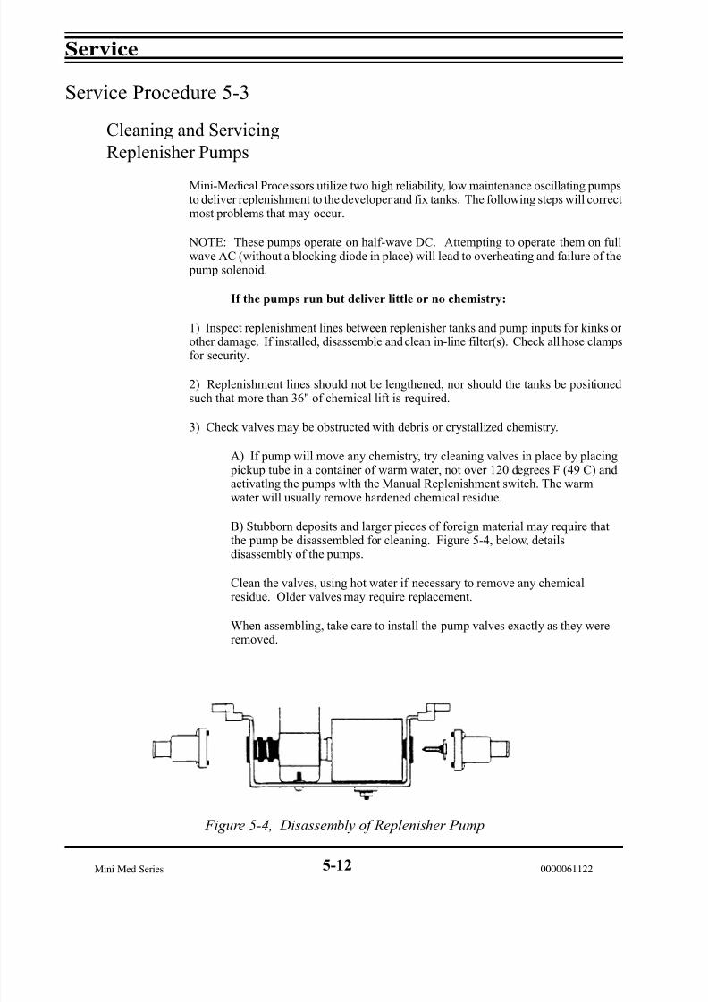
7/15/2019 Mini-medical 90
http://slidepdf.com/reader/full/mini-medical-90 78/132
Service
Mini Med Series 0000061122
Service Procedure 5-3
Cleaning and Servicing
Replenisher Pumps
Mini-Medical Processors utilize two high reliability, low maintenance oscillating pumpsto deliver replenishment to the developer and fix tanks. The following steps will correctmost problems that may occur.
NOTE: These pumps operate on half-wave DC. Attempting to operate them on fullwave AC (without a blocking diode in place) will lead to overheating and failure of the pump solenoid.
If the pumps run but deliver little or no chemistry:
1) Inspect replenishment lines between replenisher tanks and pump inputs for kinks or other damage. If installed, disassemble and clean in-line filter(s). Check all hose clampsfor security.
2) Replenishment lines should not be lengthened, nor should the tanks be positionedsuch that more than 36" of chemical lift is required.
3) Check valves may be obstructed with debris or crystallized chemistry.
A) If pump will move any chemistry, try cleaning valves in place by placing pickup tube in a container of warm water, not over 120 degrees F (49 C) andactivatlng the pumps wlth the Manual Replenishment switch. The warmwater will usually remove hardened chemical residue.
B) Stubborn deposits and larger pieces of foreign material may require thatthe pump be disassembled for cleaning. Figure 5-4, below, detailsdisassembly of the pumps.
Clean the valves, using hot water if necessary to remove any chemicalresidue. Older valves may require replacement.
When assembling, take care to install the pump valves exactly as they wereremoved.
Figure 5-4, Disassembly of Replenisher Pump
5-12
7/15/2019 Mini-medical 90
http://slidepdf.com/reader/full/mini-medical-90 79/132
Service
Mini Med Series0000061122
Service Procedure 5-4
Circuit Descriptions &
Calibration Procedures
WARNING: The following calibration adjustments are made on the Logic Board.Since potentially fatal voltages are present and easily contacted, these adjustmentsmust be performed only by qualified service technicians.
Access to the circuit cards may be gained by removing the two mounting screws fromthe underside of the feed tray, then lowering the control box door assembly.
All calibrations are done on the Logic Control Board located on the right side of theopened control box door.
Developer Temperature Control
The developer is heated by a single 500 watt heating element located under the developer tank in a heater exchange assembly.
Developer temperature is controlled by an IC temperature sensor mounted on the bottomof the developer tank. This sensor is a constant current generator who’s output is directly proportional to the temperature of the tank.
The temperature control is a proportional controller that allows full power to be sent tothe heating element during warm-up, when the processor is first turned ON. This will be indicated by the DEV TEMP light on the control panel or LED L-2 on the logic board being ON.
When the temperature in the tank is within 2 degrees f (1.1 C.) of the desired temperature,the controller will start cycling the power to the heater to prevent temperature over run.At this point the LEDs’ mentioned above will blink, indicating that the temperature isvery near its set point.
The temperature controller signals the triac switch Q2 through opto-isolator U-2 on theAC interface board. The triac switches line voltage to the heater.
The desired temperature set point is adjusted with trim pot R-20 on the logic board. NOTE: Clockwise rotation increases temperature. See Calibration Procedure below.
In the unlikely event of an electronic failure, providing continuous full power to theheating element, an overtemp safety thermostat located on the heater exchange assemblywill open, thus disabling heat. In addition, a protective internal fusible link is present inthe heating element as an added safety feature. When an open heating element is found,the operation of the triac should also be checked. (The heating element has a nominalresistance value of approximately 25 ohms).
Note that the temperature controller is disabled if a low level condition exists in thedeveloper tank.
5-13
7/15/2019 Mini-medical 90
http://slidepdf.com/reader/full/mini-medical-90 80/132
Service
Mini Med Series 0000061122
Service Procedure 5-4
Circuit Descriptions &
Calibration Procedures,
(Cont'd)
Developer Temperature Calibration
1. Verify that there is enough conductive liquid in the developer tank to cover the lowlevel sensor, located in the front wall of the tank. (About 1.5 gallons [6 L.])
2. Turn the processor ON.
3. Rotate trim pot R-20 on the Logic Board several turns clockwise to force the heater ON. The DEV HEAT LED and LED L-2 must be on steady, if not, continue turning R-20 clockwise until both LEDs’ are ON steady.
4. Place a known accurate metal stem thermometer into the developer solution.
CAUTION: Do Not use a glass/mercury thermometer in the processor. If a glassthermometer should break, the resultant mercury leakage would permanentlycontaminate the processor.
5. As the temperature of the solution reaches the desired value, slowly adjust trim potR-20 counterclockwise until LED L-2 starts to blink. When the desired temperature isreached the LED should flash ON only occasionally to indicate temperature is beingmaintained.
Dryer Temperature Control
The dryer uses two 275 watt infra-red lamps (heaters), and airflow provided by 2 fans,to dry the film as it passes through the dryer section.
A thermistor in the dryer section is used as a temperature sensor. Control is provided by the logic board. LED L-1 on the logic board will light when the dryer is calling for heat.
The temperature controller signals the Triac switch Q-1 through opto-isolator U-l onthe AC interface board. The triac switches line voltage to the heaters.
Trim pot R-21 on the logic board adjusts the set temperature of the dryer.
NOTE: Counterclockwise rotation of the trim pot increases the set temperature of thedryer.
The upper dryer blower is controlled by opto-isolator U-3 and triac Q-3. The lower, or back blower is on continuously
5-14

7/15/2019 Mini-medical 90
http://slidepdf.com/reader/full/mini-medical-90 81/132
Service
Mini Med Series0000061122
Service Procedure 5-4
Circuit Descriptions &
Calibration Procedures,
(Cont'd)
Over Temperature Protection
The dryer is equipped with over temperature protection in the form of a safety switchlocated on one of the lamp reflectors. If temperature inside the dryer exceeds 155 f (68C), the safety will open and remain open until the temperature drops below 105 f (41C).
If this should happen the dryer should be checked for dirt build up, nonoperating fansor shorted triac.
CAUTION: In no event should the processor ever be operated with this safetydevice shorted or bypassed. Severe equipment and/or personal injury could occur.
Dryer Temperature Calibration
Dryer temperature should be checked by inspecting the film being processed. If thefilm is exiting the dryer damp, temperature may need to be increased. If the processedfilm shows heat marks (wavy horizontal lines across the film) the dryer temperatureshould be reduced.
1. Inspect a piece of processed film.
NOTE: All covers and panels must be on the processor when checking operation of thedryer.
2. Adjust trim pot R-21 as follows to adjust dryer operating temperature:
Counterclockwise = Increase Dryer TemperatureClockwise = Decrease Dryer Temperature
3. Process another piece of film and inspect for proper drying.
5-15

7/15/2019 Mini-medical 90
http://slidepdf.com/reader/full/mini-medical-90 82/132
Service
Mini Med Series 0000061122
Service Procedure 5-4
Circuit Descriptions &
Calibration Procedures,
(Cont'd)
Replenishment Operation
The replenishment system operates in two modes. The first is by the film feed sensor being tripped, indicating that material is being processed. This is called automaticreplenishment. The other method is via the manual replenishment button located at thefront of the processor, known appropriately as manual replenishment.
Two trim pots on the logic board allow the adjustment of cycle length for the developer and fixer replenishment pumps, thus allowing adjustment for differing processing loads,materials and other variable conditions.
Before attempting adjustment of the replenishment system, verify that the replenisher lines are clear and not bent or kinked. If replenishment seems to be below earlier performance, clean the check valves as outlined in Service Procedure 5-3 before proceeding.
Replenishment Calibration
The following outlines basic calibration for the replenishment system. Depending onthe customer’s materials, film sizes and production, it may be necessary to make further adjustments to the replenishment rate(s).
1. Turn the processor ON.
2. Lift the developer or fixer “J-Hook” out of the processing tank far enough to hang itinto a graduated container.
3. Press the manual replenishment button until all air is purged out of the replenishmentline.
4. Empty the graduated container.
5. Feed in a piece of 14" X 17" film and measure the amount of replenishment deliveredinto the container. The recommended starting point amounts are:
Developer = 110 mlFixer = 120 ml
If these amounts are not delivered adjust the appropriate trim pot(s) shown below untilthe 1 minute delivery amount for each pump is as recommended or as required for your application. NOTE: Counterclockwise rotation increases output per minute.
Developer = R-47Fixer = R-28
5-16
7/15/2019 Mini-medical 90
http://slidepdf.com/reader/full/mini-medical-90 83/132
Service
Mini Med Series0000061122
Service Procedure 5-4
Circuit Descriptions &
Calibration Procedures,
(Cont'd)
Triacs & SCR’s
There are 5 Triac’s and 2 SCR’s on the AC interface board. Their functions are:
Ql Controls dryer heaters (lamps).Q2 Controls developer heater.Q3 Controls dryer blower.Q4 Controls drive motor and water solenoid.Q5 Not used on thls processor.Q6 Controls fixer replenishment pump.
Q7 Controls developer replenishment pump.
Outputs
The output of the AC interface board to the main harness is via connector J1 on thefollowing pins:
Pin 1 Dryer lamps (heaters).Pin 2 Developer heater.Pin 3 Drive motor, wash water replenishment pump or solenoid.Pin 4 Dryer blower.Pin 5 Not used.Pin 6 Fixer replenishment pump.Pln 7 Developer replenishment pump.
Fuses
The following fuses on the AC interface board protect the indicated circuits:
Fuse Type/Rating Protects
F1 3AGC 1 amp Developer & fixer replenishment pumps.F4 3AGC 5 amp Developer heater.F5 3AGC 8 amp Dryer lamps, 115V(heaters).F5 3AGC 5 amp Dryer lamps, 220V(heaters).
F6 3AGC 5 amp Drive motor, wash water solenoid.F7 3AGC 5 amp Dryer Blower
5-17
7/15/2019 Mini-medical 90
http://slidepdf.com/reader/full/mini-medical-90 84/132
Service
Mini Med Series 0000061122
Service Procedure 5-5
Theory of Operation
Solution Temperature Control
Temperature in the developer tank is sensed by an integrated circuit temperature sensor which generates a current that is directly proportional to temperature.
The signal from temperature sensor is sent to I.C. U2, an LM 3900 quad current-differencing amp. The amplifiers in this package amplify differences in current at itsinputs. Two of the amplifiers are connected as comparators comparing the currentgenerated by the temperature sensor with the current set by the front panel temperaturecontrol. R20 sets the maximum temperature at which the front panel control can be set.R20 is preset at the factory for approximatly 110°F maximum temperature.
When replacing the Logic board or when replacing U2 or the temperature sensor, R20must be re-calibrated (see calibration Procedures). The other two amplifiers in U2 areused as a triangle wave signal which is mixed with the current from the controls. Thisgives proportional temperature control supplying less heat as the temperature approachesthe set temperature, and automatically adjusts the amount of heat supplied to maintaintemperature as closely as possible. The action of the temperature control is indicated by the LED lamp on the front panel and L2 on the Logic Board. When the lamp is on,the heater is activated.
As the tank temperature approaches the set temperature, the LED will begin blinkingand will remain on for less time as the temperature comes closer to the set temperature.
Drive to the heater is disabled if the solution level in the developer tank drops below thelevel sensor probe.
Dryer Temperature Control
Temperature in the dryer transport is sensed by an integrated circuit temperature sensor which generates a current that is directly proportional to temperature.
The signal from the temperature sensor is sent to I.C. U2, an LM 3900 quad current-differencing amp. The amplifiers in this package amplify differences in current at itsinputs. Two of the amplifiers are connected as comparators comparing the currentgenerated by the temperature sensor with the current set on the board. R21 sets thetemperature for the dryer. R21 is preset at the factory for 135°F maximum temperature.
When replacing the Logic board or when replacing U2 or the temperature sensor, R21
must be re-calibrated (see calibration Procedures). The other two amplifiers in U2 areused as a triangle wave signal which is mixed with the current from the controls. Thisgives proportional temperature control supplying less heat as the temperature approachesthe set temperature, and automatically adjusts the amount of heat supplied to maintaintemperature as closely as possible. The action of the temperature control is indicated by the LED L1 on the logic board. When the lamp is on, the heater is activated.
As the dryer temperature approaches the set temperature, the LED L1 will begin blinkingand will remain on for less time as the temperature comes closer to the set temperature.
5-18
7/15/2019 Mini-medical 90
http://slidepdf.com/reader/full/mini-medical-90 85/132
Service
Mini Med Series0000061122
Service Procedure 5-5
Theory of Operation
(Cont'd)
Solution Level Sensor
A metal screw located in the developer tank detects when the solution level becomes solow that there is a danger of the heater becoming dry. If the developer level drops below the end of the metal screw, the red Low Solution light will turn on to warn theoperator. When the red light is on, the heater is turned off to prevent tank damage. If anattempt is made to run the processor, it will turn on as usual but the red Low Solutionlight will begin to blink, drawing attention to the problem. When the solution level inthe tank is again at the proper level, the red light will go out and heating will automaticallyresumes.
Automatic Shut-Off
The processor is preset at the factory to shut off and go into a standby mode approximately5 minutes after the sensor(s) in the film entry lip is released by the trailing edge of thefilm.
This time interval is controlled by adjusting Pot R29. R29 adjusts the frequency of anoscillator in U6. The output of the oscillator is sent to U5 which divides the frequency by 16,384. The oscillator is adjusted so that after division, one pulse is output by U5after approximately 4 minutes. When the sensor is triggered by film presence, it resetsU5 to zero and holds it there. When the sensor is released, U5 again functions andoutputs its pulse after approximately 5 minutes. The output of U5 goes to a flip flop(U4) which turns off all machine functions except solution temperature control,recirculation pumps and one (1) dryer blower.
When the reset pushbutton is depressed, the timer is disabled and all machine functionsrun continuously.
AC Interface Board
This board connects the low voltage signals from the main logic board and uses them toswitch the various AC components in the machine on and off.
The low level signals are interfaced by six optically isolated TRIAC TRIGGERS (Ul-U7). These contain an LED which is optically coupled to a small TRIAC Trigger. TheLED in the Trigger is connected in series with the appropriate control panel LED whichindicates whether each component is operating. If either the trigger LED is bad or the
control panel LED is bad, the circuit will not operate.
5-19

7/15/2019 Mini-medical 90
http://slidepdf.com/reader/full/mini-medical-90 86/132
Service
Mini Med Series 0000061122
Waveforms & Voltages
0V
1V
2V
3V
1.121s
1.134s
0
1.7V
2.7V
1. Pin 4 of U2 on Logic Board
2. Pin 9 of U2 on Logic Board
11V
0V
15ms1 Pulse
7 Pulse Bursts
3. Pin 5 of I.C. U2 on Logic Board
1.13s
11.25 V
0V
Note: Duty cycle = 34%
4. Pin 12 of I.C. U4 on Logic Board = 2.4VDC
5. Pin 13 of I.C. U4 on Logic Board = 0VDC
6. Pin 11 of I.C. U4 on Logic Board = 11.9VDC
7. Pin 5 of I.C. U1 on Logic Board = 11.38VDC
600ms
12 V
Note: Duty cycle = 50%
8. Pin 7 of I.C. U5 on Logic Board
9. Pin 18 of I.C U7 on Logic Board = 10 VDC
10. Pin 15 of I.C. U7 on Logic Board = 0VDC
550ms
Note: Duty cycle = 12%Pulse present only whileReset Pushbutton isdepressed.
0V
9.5V
0V
5-20

7/15/2019 Mini-medical 90
http://slidepdf.com/reader/full/mini-medical-90 87/132
Service
Mini Med Series0000061122
11. Pin 11 of I.C. U6 on Logic Board = 0VDC
550ms
Note: Same as #10, butinverted. Duty cycle = 88%Pulse present only whileReset Pushbutton isdepressed.
0V
9.5V
12. Pin 17 of I.C. U7 on Logic Board = Same as #11 only whileReset Pushbutton is depressed. 5 second duration
13. Pin 14 of I.C. U7 on Logic Board = Same as #10
14. Pin 10 of I.C. U6 on Logic Board = Same as #'s 11&12
15. Pin 8 of I.C. U6 on Logic Board
10V
5V
8.25V
4.7 Sec
10V
572 ms
36 ms16. Pin 13 of I.C. U6 on Logic Board
1V
11.88V
41 Sec
Ready Tone Generator Board
Middle pin of J13 = Low (Gnd)when no film is present
= High (12V)when film is present
Middle pin of J12 = Low (Gnd)when no film is present
= High (12V)when film is present
Output of either Q1 or Q2 = 12Vwhen either input goes high
Pin 5 of I.C. U1 = Output of Q1or Q2 Inverted.
Pin 6 of I.C U2 = high (12V) normallyLow pulse when film exits
12V
0V
35 ms
Waveforms & Voltages
(Cont'd)
5-21

7/15/2019 Mini-medical 90
http://slidepdf.com/reader/full/mini-medical-90 88/132
Service
Mini Med Series 0000061122
Main Wiring Diagram
Figure 5-5, Main Wiring Diagram
5-22
J 1 2
J 1 1
J 1 0
J 8
J 6
J 5
J 4
J 3
J 2
J 9
L O W E R
D R Y E R F A N
I R L A M P S ( 2 )
D R Y E R
U P P E R
D R Y E R F A N
D R I V E
M O T O R
S O L E N O I D
D E V
R E
C I R C
D E V
R E P L E N
D E V
H E A T E R
F I X
R E C I R C
F I X
R E P
L E N
W A S H
T E M P
O V E R
T E M P
O V E R
1 / 2 A
1 / 2 A
5 0 0 W
1 / 2 A
1 / 2 A
1 / 2 A
1 / 2 A
2
7 5 W
E A
1 / 2 A
2 A
G R N
B L U
B L K
B L K
B L K
G R N
B L U
V L T
G R Y
J 7
J 2
J 9 / J 2 0
G R Y
V L T
B R N
O R N
B L U
G R N
W H T
G R Y
B L K
Y E L
V L T
R E D
P N K
B L K / H O T
W H T / N E U T
G R N / G N D
M A I N H A R N E S S P C B P / N 3 5 3 1 6
J 1 4
1 2 3
O R B
R
E A D Y T O N E
G
E N E R A T O R
3 5 3 0 6 - 1
1 2 3
J 1 3
1
2
3
4
L E D P C B
P / N 3 5 2 9 9
1
2
3
4
5
6
7
8
B R O Y G B V G
R E E D S W I T C H E S
P N K
R E D
V L T
Y E L
B L K
G R Y
W H T
G R N
B L U
O R N
B R N
L E V E L
S E N S O R
D R Y
S E N S O R
S E N S O R
D E V
M A I N
S W I T C H
S W I T C H
R E P L .
S W I T C H
C O V E R
P O W E R S O U R C E
J 2
P O W E R B O A R D
P / N
3 5 2 3 3
J 3
4 3
2
1
8
7
6
5
4
3
2
1
J 1
F I X , D E V R E P L .
F 1
1 A
1 A
F 3
A U X A C
F A N S
F 7
5 A
D E V H E A T
F 4
5 A
D R Y E R
F 5
P U M P , F A N / M O T O R
F 6
3 A
1 2 3 4 5 6 7 8
5 A - 2 3 0 V A C
8 A - 1 1 5 V A C
2 3 0 V A C P / N 3 5 3 0 4
1
2
3
4
5
6
7 T B 1
1 1 5 V A C P / N 3 5 3 0 2
L O G I C B O A R D
R 2 1
R 2 0
1 2 3 2 1
J 1 2
J 1 3
J 1 4
2 1
J 9
2 1
2 1
J 2 0
J 8
1 2 3
1
2
3
4
5
6
7
8
J 7
J 4
1 2
J 5
1 2 R
4 7
R 2 8
R 2 9
D E V T E M P
D R Y T E M P
D E V R E P L S E T
F I X R E P L S E T
T I M I N G
6
C H A N N E L C O N T R O L L E R
1 1 5 V A C / 2 3 0 V A C
J 1 1 2 3 4 5 6 7 8
N O N E
D E V E L O P E R R E P L E N I S H
F I X E R R E P L E N I S H
A U X . A C
N O T U S E D
D R Y E R F A N S
D R I V E M T R . W A S H S O L .
D E V E L O P E R H E A T
D R Y E R H E A T
F U N C T I O N
N O N E
S C R
Q 7
S C R
Q 6
Q 5
T R I A C Q 3
T R I A C Q 4
T R I A C Q 2
T R I A C Q 1
C O N T R O L E R
1 2 3 4 5 6 7 J 2 -
P O W E R P C B O
A R D
P / N 3 5 2 3 3

7/15/2019 Mini-medical 90
http://slidepdf.com/reader/full/mini-medical-90 89/132
Service
Mini Med Series0000061122
4 B L AC K 2 2 A WG
5 W H I T E 2 2 A W G
6 G R E E N
B R O W N 1
O R A N G E 2
W H I T E 3
WHT BLK BRN22AWG
RIBBON
L O G I C P C
B O A R D
J5
D R Y E R
H E A T
D R Y E R
F AN
R I B B O N
2 2 A W G
BLKWH T 1
B
R
N
2
G
R
N
3
W
H
T
1
O
R
N
2
G
R
N
3
W
H
T
H E A T E R S
H E A TS E N S O R
2
6
31
4
5
FAN
ORN
S A F T Y
O V E R T E M P
WHTGRN
1 2 3 4 5 6 7 8 8 7 6 5 4 3 2 1
Dryer Rack Wiring Diagram
5-23
Figure 5-6, Dryer Rack Wiring Diagram
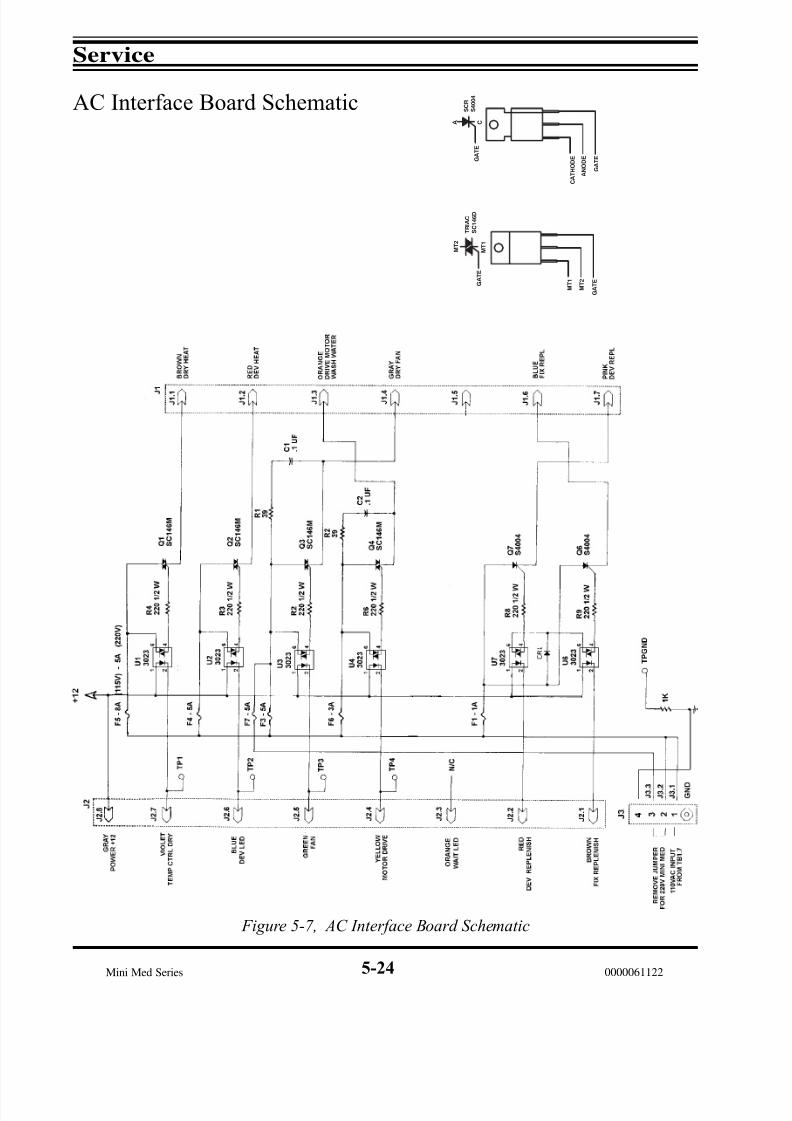
7/15/2019 Mini-medical 90
http://slidepdf.com/reader/full/mini-medical-90 90/132
Service
Mini Med Series 0000061122
Figure 5-7, AC Interface Board Schematic
AC Interface Board Schematic A C
G A T E
S C R
S 4 0 0 4
C A T H O D E
A N O D E
G A T E
M T 2
M T 1
G A T E
T R I A C
S C 1 4 6 D
M T 1
M T 2
G A T E
5-24

7/15/2019 Mini-medical 90
http://slidepdf.com/reader/full/mini-medical-90 91/132
Service
Mini Med Series0000061122
Logic Board Schematic
Figure 5-8, Logic Board Schematic
5-25
Q 1 7
Q 1 6
4 3 1 1
1 0
8 9 1 2
1 3
1 2 6 5
D E V T E M P
O T H E R W I S E S P E C I
F I E D
S P E C I F I E D
U N L E S S O T H E R W I S
E
A L L R E S I S T O R S A R
E
I N O H M S U N L E S S
A L L C A P A C I T O R S
A R E I N u
f
3 0 K
J U M P E R F R O M
1 N 3 0 6 4 O R 1 N 9 1 4
L O G I C T O J O G
B O A R D
D R Y E R P R O B E
D E V P R O B E
+
-
A D 5 9 0
+
-
6 . 8 K
R 5 0
J 5
R 2 3
2 7 K
R 1
8
U 3 M C I 4 0 8 1
I
U 6
, U 6 A C D 4 0 9 3 B C N
U 7 U L N 2 8 0 4 A
V R 1
, V R 2 L M 7 8 1 2 C T
U 4 C D 4 0 0 1
U 5 M C 1 4 0 2 0
L O
E V
S H N I
U 3
U 3
1 0 K
U 2 L M 3 9 0 0
U 1 N E 5 5 6
J 8
L O W
L E V E L
P R O B E
5 9
R 2 1
1 4
U 2
1
7
+ 1 2
6
C 8 0
2 0 K
R 2 0
1 3
1 0 0 K
R 2 2
+
U 2
-
8
1 3
1 2
R 2 5
1 0 K
R 2 6
5 6
1 1
U 4
3
9 8
M T D R 9 3
J 2 0 L
O W L E V E L
L E D
P E R Y
1 0 u f / 2 0
C 1 7 A
+ 1 2
C R 2 7
W
O
T
N R T C O
R D
D E
R
L
N A
D
F
E V
M O T
A I
P E L R E D
F
E V
I X
R 2 4
8 3 R
1 4
0 4
R
R
R
3 4
4 4
R
U 7
7 5 0
4
R 2 7
1 6
8
1 1
U 7
3 3 0
R 4 8
1 0
1 2
7
U 7
7
A D 5 9 0
6 . 8 K
R 4 9
J 4
+ 1 2 F 1
T B 1
M O V
6 5 1
6
7 8 1 2
+ 1 2 J 1 3
V R 2
2
1 0
1 2
1 M R
1 3
1 M
R 1 9
4 7 0 K
R 1 4
U 2
+
1 1
- 1 0 0 K
R 1 7
1 0 u f / 2 0 V
1 N 4 0 0 2
C 3 A
R 1 5
1 5 0 K
1 M
R 1 2
3
U 2
+ -
4
4 7 0 u f / 3 5 V
C 1 7
1 3
6
U 7
3
2 N 4 4 0 1
Q 2
2 U 3
1
J U M P E R
V R 1
7 8 1 2
C R 8
1 N 4 0 0 2
C R 9
1 4 A
- 1 0 R
- 2 8
4 3 1
9 1 2
1 0 7
S W I T C H
C 3 2
2 2 0 0 u f
2
1
2
1
J 1 4
T O P
C O V E R S A F E T Y
T O J 1 F R O M U 6
+ 1 2 L O G I C
1 0 u f / 2 0 V
1 0 u f / 2 0 V
3
C 5
3
C 4
G N D
R I B B O N C A B L E
S R 1 6
2 0 K
N O T U S E D
J 7
C R 1 6
C R 1 7
R 3 2
1 0 K
J O G / F L O O D
J O G O N L Y
G E N E R A T O R
R E A D Y T O N E
1 + 1 2
1 m
D E V R E P L
R 4 7
1 0 0
M A N U A L
R E P L E N I S H M E N T
J 1 2
S W I T C H
1
2
S R 1 7
2 0 K
J 1 3
2 N 2 9 0 7
R 1 0
1 7 U
7
2
C R 1 8
1 4
R 4 5
3 . 3 K U
7
5
P O W E R O N
J
9
2
3
1
2 L E D
C R 2 5
R 1 1
3 9 K
R 3 7
1 u f
U 6
4 1 0 0
6 5
U 6
C R 1 9
1 0
8
C 1 2
9
C 3
J 1 . 1
1 m
F I X R E P L
R 2 8
C R 2 4
6
R 3 1
2 N 2 9 0 7
1 8 U
7
1
C R 2 0
1 5
3 . 3 K U
7
4
2 2 0 K R
4 6
8
U 4 U 4 4 3
5 2 1
C R 2 3
U 4
1 0
9 8
7 1 1
U 5
3
1 6
U 6 A
J 1 . 7
J 1 . 2
J 1
U 6
C R 2 1
R 3 6
1 0 0
1 1
C 1 6
1 u f
1 3
1 2 1
1 u f
C 7
R I B B O N C A B L E
C 8
1 u f
F R E Q . A D J .
U 6
R 3 5
3 6 K
1 0
3
2
5 0 0 K
R 2 9
1 0 u f
T O
+ 1 2
3
J 1 . 1 2
C R 2
J 1 . 5
J 1 . 6
J 1 . 3
J 1 . 4
J 1 . 1 1
J 1 . 9
J 1 . 1 0
C R 1
U 6 A
U 6 A
J 1 . 1 3
6 U 1
4
U 6 A
J 1 . 8
J 1 . 1 4
1 M
C 2
. 0 1 u f
2 1 M
R 1 A
1
9
7
1 1
U
1
1 0
1 4
1 0 0 u f / 2 0 V
C 1
R 1
1 0 0 u f
2 0 V
1 0 0 K
. 0 1 u f
C 4
1 2
C 5
1 3 8
R 3
R 2
1 M
2 . 2 M
R 2 A
L 1
L 2
L 3 L 4
L 5
L 6
N O T E : R 3 8 - R 4 4
= 7 5 0
+ 1 2
1
2
3
+ 1 2
R 5
2
1 m
+
+
+
7 1 4
+ +
+
9
+
1 2 1 2
+ 1 2
+ 1 2
1
2
3
1
2
1
2
3
4
5
6
7
8
+ 1 2
+ 1 2
7 8 1 2

7/15/2019 Mini-medical 90
http://slidepdf.com/reader/full/mini-medical-90 92/132
Service
Mini Med Series 0000061122
Logic Board Layout
Figure 5-9, Logic Board Layout
5-26
LOGIC BOARD AFP 35302
FUSE 1/4 AMP
TB1
C80
JOG/FLOOD
L2
R 1
7
-
R20+
R 1
5
R 1 8
R 1 3
R 4 9
R 2 3
J4
R 1 9
R 1 4
C1U6A
L1 J7J20
C15
R21
J5
R 5
0
U2 R 2 2
C3A
35302
JUMPER
ONLY
+
-
R 1 2
U3
C33
CR1
R2A
R2
R 4 1
R 3 8
R 3 9
R 4 0
C17A
L3
R 4 3
R 4 2
R 4 4
L4 R 2 6
U7
JOG ONLY
2
J1
1
C5A
C4A
U1
R3
3 4 5
R 1 A
C3
R 1
C2
6 7
R29
C5
C4
CR24
L5
R31
L6
C R 2 1
C R 1 9
C17
R30
J8
R 2
5
R 4 6
R 4
5
R 2
7
R 4 2
C R 2 0
U4
R 3 2
R 3 6
CR27
C R 1 8
Q2
R 3
7
MOV
U5
U6
C10
C16
R28
CR23
R 3
5
R47
C14
C12
C8
C9
C7
R 1 1
C6
J9
CR25
J13
R10
J12
J14
VR2T1
R 8
VR1
+ C32
CR9
CR8
WHITE WIRETO HARNESS
SINGLE BLACK WIRE TO HARNESS
YELLOW WIRETO MAIN HARNESS BOARD (BK3)
SINGLE BLACK WIRE TO TERM 1 OF AC BOARD
TO INTERRUPTERSWITCH
TO MAIN SWITCH(Two individual
Yellow & OrangeWires - NOT ribbon)
TO READY TONEGENERATOR BOARD
TO LED BOARD(Purple/Grey
Ribbon)
LEVEL SENSOR
TO LED BOARD(Blue/Green Ribbon)
LEDBOARD
DRYER TEMPSENSOR
DEV TEMPSENSOR
SINGLE ULTRAVIOLETWIRE TO HARNESS BOARD
R52
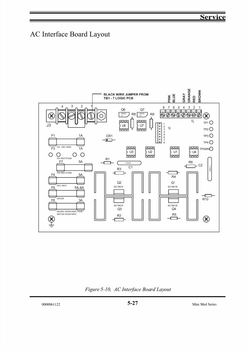
7/15/2019 Mini-medical 90
http://slidepdf.com/reader/full/mini-medical-90 93/132
Service
Mini Med Series0000061122
AC Interface Board Layout
Figure 5-10, AC Interface Board Layout
5-27
Q1
Q4
S C 1 4 6 M
S C 1 4 6 M
R5
R4
4
R1
M O T O R W A S H R E P L .
R E C I R C W A S H R E P L F A N S
F I X , D E V R E P L
F I X H E A T / F A N S
F I X H E A T / F A N S
F5
F6
F4
D E V H E A T
D R Y E R
F3
F1
F7
3A
5 A - 8 A
5A
1 A
5A
1 A
S C 1 4 6 M
Q3
R2
C 1
S C 1 4 6 M
Q2
R3
C R1
U3
. 1 1 0 0 0 V
U2
6
7
5
8
34 2
J3
1
Q6
F 1
U6
S 6 0 1 0 R8 R9S 6 0 1 0
F 1
U7
Q7
1
2
3 J 2
8 7
TP2
R1 0
C 2R6
U1 U4
.1 1 0 0 0 V
TPGRN
TP3
TP4
356 4
J 1
2 1
TP1
P I N K
B L U E
G R A Y
O R A N G E
R E D
B R O W N
B L A C K W I R E J U M P E R F R O M
T B 1 - 7 L O G I C P C B

7/15/2019 Mini-medical 90
http://slidepdf.com/reader/full/mini-medical-90 94/132
Service
Mini Med Series 0000061122
Ready Tone Generator Layout & Schematic
Figure 5-11, Ready Tone Generator Layout & Schematic
(For Serial #'s 1900 And Higher)
J14 J13
+
+
+
+
+
T R G 1
C N T 1
R S T 1
T R G 2
C N T 2
R S T 2
D C G 2
T H R 2
O U T 2
D C G 1
T H R 1
O U T 1
V C C
G N D
J 1 3
J 1 4
T O
F I L M
S E N S O R
T O
F I L M
S E N S O R
R 1 1
1 0 K
R 1 3
1 0 K
Q 1
Q 3
2 N 2 2
2 2
2 N 2 2
2 2
U 1
1 N 4 3 7
R 3
1 K
R 2
3 9 0
C 2
1 u f R
9 5 . 1
K
C 1
3 3 u f
C R 1
1 N 4 0 0 4
R 4
1 0 K
R 1
3 9 0
Q 2
2 N 2 2 2 2
O R N
R E D
B R N
G
N D
V C C
F R O M
J 1 3 L O G I C
P C B
R 5
1 0 K
R 6
1 K
C 4
1 u f
C 3
. 1 u f
C 5
. 1 u f
U 2
N E 5 5 6
6 3 4 8 1 1
1 0
5 2 1 9 1 2
1 3
1 4
C 8
. 1 u f
R
7
6
8 K
R 8
1 0 0 K
C
6
1 0 0 u f
C 7
1 0 u f
V C C
B 1
B E E P E R
-
+
R 1 2
1 0 K
R 1 0
1 0 K
6 5 4
1 2 3
5-28

7/15/2019 Mini-medical 90
http://slidepdf.com/reader/full/mini-medical-90 95/132
Service
Mini Med Series0000061122
Figure 5-12, Ready Tone Generator Schematic
(For Serial #'s Below 1900)
+
+
+
+
+
P i n # 3
P i n # 2
P i n # 1
P i n # 3
P i n # 2
P i n # 1
T R G 1
C N T 1
R S T 1
T R G 2
C N T 2
R S T 2
D C G 2
T H R 2
O U T 2
D C G 1
T H R 1
O U T 1
V C C
G N D
P J 1 3
3 9 0
R 1
R 2
3 9 0
R 9
5 0 K
C 1 3
3 u
f
R 3
1 K
C 2
1 u
f
R 4
1 0 K
C R 1
1 N 4 0 0 4
2 N 2 2 2 2 A
Q 2 R
5 1 0 K
R 6
1 K
C 4
1 u
f
U 2
N E 5 5 6
1 4
C 3
C 5
1 u
f
1 u
f
+ 1 2
6 3 4 8 1 1
1 0
5 2 1 9 1 2
1 3
7
C 5
. 1 u f
C 6
1 0 0 u f
C 7
1 0 u f
B
E E P E R
-
+
R 7
6 0 K
R 8
1 0 0 K
U 1
4 N 3 7
1 2 3
6 5 4
U 1
1 N 4 3 7
5-29

7/15/2019 Mini-medical 90
http://slidepdf.com/reader/full/mini-medical-90 96/132
Service
Mini Med Series 0000061122
LED Board Layout & Schematic
Figure 5-13, LED Board Layout & Schematic
LED PCB MINI MED
POWER
DEV
WAIT
LOW LEVEL
(TO J9 & J20)
BROWN
RED
ORANGE
YELLOW
GREEN
BLUE
VIOLET
GRAY
R2750
R1750
5-30

7/15/2019 Mini-medical 90
http://slidepdf.com/reader/full/mini-medical-90 97/132
AFP Mini-Medical
X-Ray Film Processors
- General Index -
Section 0 - Safety Information
Section 1 - Introduction
Section 2 - Installation
Section 3 - Operation
Section 4 - Maintenance
Section 5 - Service
Section 6 - Parts
Section 7 - Accessories
0000061122
Section 6 Parts

7/15/2019 Mini-medical 90
http://slidepdf.com/reader/full/mini-medical-90 98/132
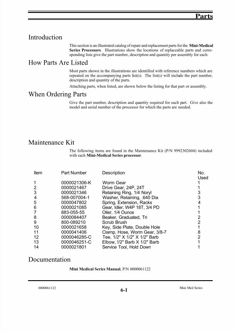
7/15/2019 Mini-medical 90
http://slidepdf.com/reader/full/mini-medical-90 99/132
Parts
Mini Med Series0000061122
IntroductionThis section is an illustrated catalog of repair and replacement parts for the Mini-MedicalSeries Processors. Illustrations show the locations of replaceable parts and corre-sponding lists give the part number, description and quantity per assembly for each.
How Parts Are ListedMost parts shown in the illustrations are identified with reference numbers which arerepeated on the accompanying parts list(s). The list(s) will include the part number,description and quantity of the parts.
Attaching parts, when listed, are shown below the listing for that part or assembly.
When Ordering PartsGive the part number, description and quantity required for each part. Give also themodel and serial number of the processor for which the parts are needed.
Maintenance KitThe following items are found in the Maintenance Kit (P/N 9992302604) includedwith each Mini-Medical Series processor.
Documentation
6-1
Mini Medical Series Manual, P/N 0000061122
Item
12345678910
11121314
Part Number
0000021306-K00000214670000021346568-007004-100000478020000021085883-055-550000084407800-0892100000021658
00000414060000046285-C0000046251-C0000021801
Description
Worm Gear Drive Gear, 24P, 24TRetaining Ring, 1/4 NorylWasher, Retaining, .640 DiaSpring, Extension, RacksGear, Idler, W4P 18T, 3/4 PDOiler, 1/4 OunceBeaker, Graduated, TriScrub BrushKey, Side Plate, Double Hole
Clamp, Hose, Worm Gear, 3/8-7Tee, 1/2" X 1/2" X 1/2" BarbElbow, !/2" Barb X 1/2" BarbService Tool, Hold Down
No.Used1133411221
8211

7/15/2019 Mini-medical 90
http://slidepdf.com/reader/full/mini-medical-90 100/132
Parts
Mini Med Series 0000061122
General Assembly
6-2
Item
12345
678910111213141516171819
20212223
242526272829303132
3334
Part Number
0000021257-20000021421-1See Pgs 4 & 500000217000000021701
568-0070740000022120N/A00000218450000021846N/A00000218810000022003See Pgs 4 & 50000021442568-007064-1000003711200000372830000044755
00000370510000046251-C0000047833000008722200000872200000046191-E0000046291-B0000046300-A95260626409527062640952806264000000326790000021795000-09000-AA-H
000-05400-AM-H9992305005
Description
Tank/Frame UnitSide Cover Cover, Elect. Door Panel, DrainClamp, Panel, Drain
Tank, 7 Gal. Replenisher Dip Tube Assy, Repl. TankN/AFront Top Cover Rear Top Cover N/ARear Top Cover (Rear Exit - NotShown)Foot, MoldedFilm Feed TrayFeed Tray Cover Floating LidManual Replenishment SwitchCircuit Breaker, 15 AmpLeveling Foot
Interrupter Switch, Rear Elbow, 1/2"Spring, CompressionBall Valve, Drain (Gray W/Blue Handle)Ball Valve, Drain (Black older style)Nipple, 1/4 X 2 In ToeWash Water HoseHose GasketTubing, 1/2" I.D. X 11/16" O.D. Clear Tubing, 1/2" I.D. X 11/16" O.D. RedTubing, 1/2" I.D. X 11/16" O.D. BlueCover, interrupter switch, harnessPlate, interrupter switchFlat washer, switch
Mounting screws, switchReplenisher Tank Set, 7 Gal.
No.Used12111
22N/A11N/A14111114
134333124 ft.4 ft.4 ft.111
11
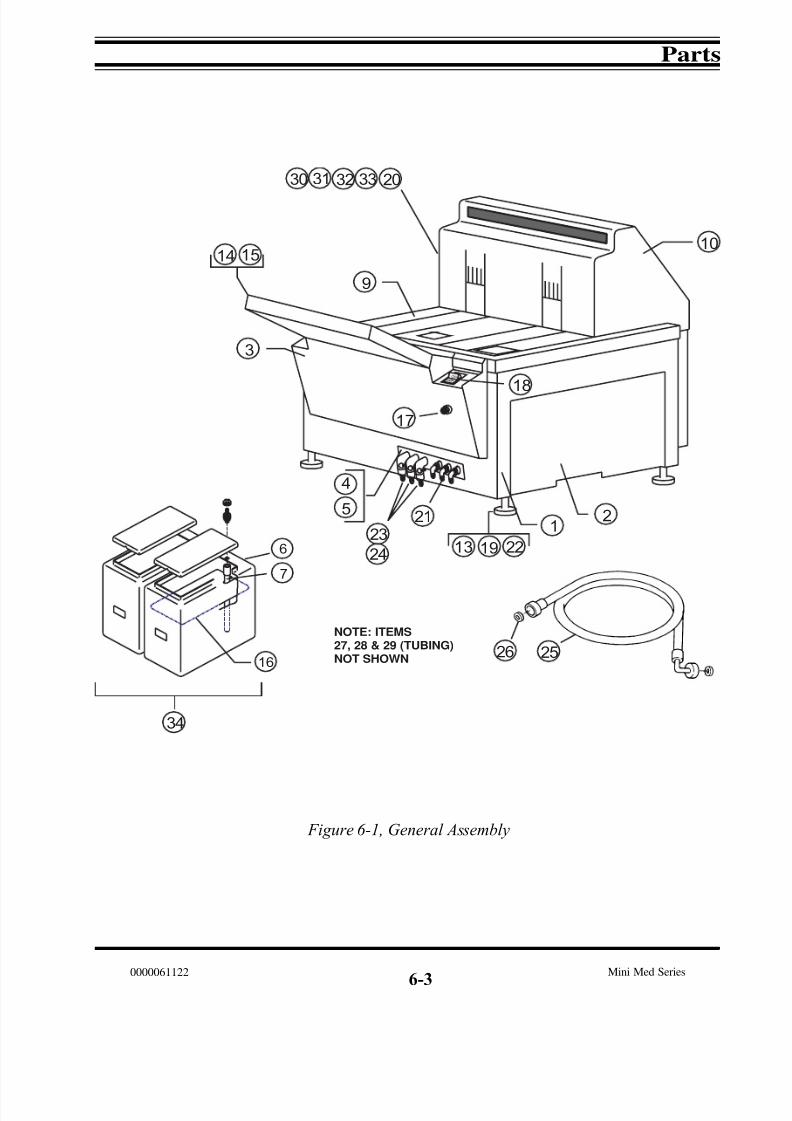
7/15/2019 Mini-medical 90
http://slidepdf.com/reader/full/mini-medical-90 101/132
Parts
Mini Med Series0000061122
Figure 6-1, General Assembly
6-3
O N
3
4
5
9
1 0
24
1 4 1 5
7
6
1 6
12
1 3
20
22
21
2526
1 7
1 8
1 923
NOTE: ITEMS27, 28 & 29 (TUBING)NOT SHOWN
33323130
34

7/15/2019 Mini-medical 90
http://slidepdf.com/reader/full/mini-medical-90 102/132
Parts
Mini Med Series 0000061122
1
2
3
4
5
6
7
8
9
10 11
12
13
14
15
16
17 18
(To J20 & J9
on Logic Board)
(To J2 Inputon A.C. Board)
6-4
Figure 6-2a, Feed Tray & Control Chassis Assembly
Item
123456789
10111213141516
1718
Part Number
00000214410000021442000002069200000214400000021539000002161800000372830000021461-30000035299
00000326510000032650000004558400000217030000021459-100000353060000035302000003530400000352330000037112
Description
Film Feed Tray, (1 Sensor)Cover Assy, Feed TrayRoller Assy, Feed Tray Adaptor, Feed Tray, MoldedPendulum Assy, (1 Sensor) Assy, Film Presence SwitchSwitch, Circuit Breaker, 15 AmpBracket, L.E.D.P.C.B. Assy, L.E.D.
Harness, Logic/L.E.D., 4-PinHarness, A.C./L.E.D., 8-PinLabel, Control Panel, MMStrap, Cover Cover, Front, Electronic, MountingP.C.B. Assy, Ready Tone Board, (1 Sensor)P.C.B. Assy, Logic Board (115V)P.C.B. Assy, Logic Board (230V)P.C.B. Assy, Power BoardSwitch, Manual Replenishment
No.Used111111111
1111111
11

7/15/2019 Mini-medical 90
http://slidepdf.com/reader/full/mini-medical-90 103/132
Parts
Mini Med Series0000061122
Figure 6-2b, Feed Tray & Control Chassis Assembly
6-5
1
2
3
4
5
67
8
910
11
12
13
1415
16
17
18
(To J20 & J9
on Logic Board) (To J2 Input
on A.C. Board)
2019
NOTN) G2 60HZ O 60HZ
21
23
22
Item
12
3456789101112131415
1617
1819202122
23
Part Number
00000218760000021442
0000020692000002189300000218740000021462-300000372830000031713000-00706-BA-H00000218780000021461-30000035299000004558400000326510000032650
00000218750000035302000003530400000352330000035306-1000003711200000217030000038096
0000038095
Description
Film Feed Tray, (2 Sensor)Cover Assy, Feed Tray
Roller Assy, Feed TrayPendulum Assy, (2 Sensor) Adapter, Feed Tray, (2 Sensor)Bracket, SwitchSwitch, Circuit Breaker, 15 AmpMount, TieScrew, 6-32 X 3/8", Slot Pan HeadFilm Presence Switch Assy (2 Sensor)Bracket, L.E.D.P.C.B. Assy, L.E.D. BoardLabel, Control PanelHarness, Logic/L.E.D.Harness, A.C./L.E.D., 8-Pin
Cover, Front, Electrical, MountingP.C.B. Assy, Logic Board (115V)P.C.B. Assy, Logic Board (230V)P.C.B. Assy, Power BoardP.C.B. Assy, Ready Tone Board (2 Sensor)Switch, Manual ReplenishmentStrap, Cover Assy, Transformer, Dryer Harness (230VAC Only)S/N 8676 and below Assy, Transformer, Drive Motor (230V/60Hz Only)
No.Used11
1211122211111
11111111
1
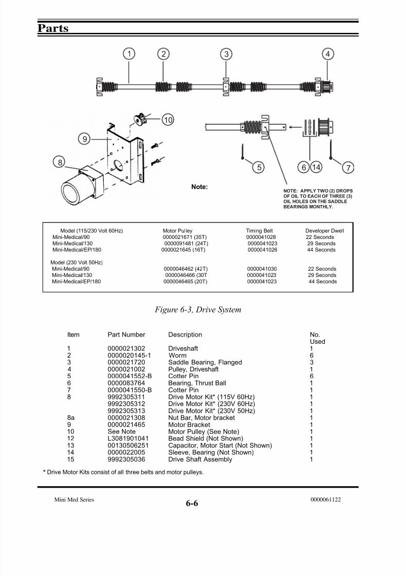
7/15/2019 Mini-medical 90
http://slidepdf.com/reader/full/mini-medical-90 104/132
Parts
Mini Med Series 0000061122
6-6
Figure 6-3, Drive System
Item
12345678
8a91012131415
Part Number
00000213020000020145-1000002172000000210020000041552-B00000837640000041550-B9992305311
9992305312999230531300000213080000021465See NoteL30819010410013050625100000220059992305036
Description
DriveshaftWormSaddle Bearing, FlangedPulley, DriveshaftCotter PinBearing, Thrust BallCotter PinDrive Motor Kit* (115V 60Hz)
Drive Motor Kit* (230V 60Hz)Drive Motor Kit* (230V 50Hz)Nut Bar, Motor bracketMotor BracketMotor Pulley (See Note)Bead Shield (Not Shown)Capacitor, Motor Start (Not Shown)Sleeve, Bearing (Not Shown)Drive Shaft Assembly
No.Used16316111
111111111
Model (115/230 Volt 60Hz) Motor Pulley Timing Belt Developer Dwell
Mini-Medical/90 0000021671 (35T) 0000041028 22 Seconds
Mini-Medical/130 0000091481 (24T) 0000041023 29 Seconds
Mini-Medical/EP/180 0000021645 (16T) 0000041026 44 Seconds
Model (230 Volt 50Hz)
Mini-Medical/90 0000046462 (42T) 0000041030 22 Seconds
Mini-Medical/130 0000046466 (30T 0000041023 29 Seconds
Mini-Medical/EP/180 0000046465 (20T) 0000041023 44 Seconds
Note:
1 2 3 4
5 6 78
9
1 0
N O T E : A P P L Y T W O ( 2 ) D R O P SO F O I L T O E A C H O F T H R E E ( 3 )
O I L H O L E S O N T H E S A D D L EB E A R I N G S M O N T H L Y .
1 4
* Drive Motor Kits consist of all three belts and motor pulleys.

7/15/2019 Mini-medical 90
http://slidepdf.com/reader/full/mini-medical-90 105/132
Parts
Mini Med Series0000061122
Frame/Tank Assembly
Figure 6-4, Tank/Frame Assembly
6-7
Item
12
345678
910111213
1415161718192021
22
23
Part Number
00000218690000021848-100000208640000021848-200000381500000045805000-06000-AA-R00000458220000045825000002099500000f20995-10000083915(See Pg. 6-8)0000021436000002164299923053110000021507000003890400000213080000021668000002166600000203540000021210568-0070380000045824000-06702-AA-R000004900800000490130000048326
Description
Overtemp Safety ThermostatHeater Weldment, 500W (115V)Heater Assembly, (115V, S/N 1534 and Lower)Heater Assembly, (230V)Temperature Sensor "O" Ring, Temperature Sensor Nylon Nut, Temperature Sensor "O" Ring, Size 008, Recirculation Pump"O" Ring, Size 025, Recirculation PumpReplenisher Pump (115V)Replenisher Pump (230V)Poppet Valve, Replenisher PumpRecirculation PumpRubber TeeRestrictor For Dev Inlet Elbow (Not Shown)Drive Motor Assembly (115V, See Fig 6-3)Drive Motor (230V, See Fig 6-3)Line Cord Assy, 14/3, 6' W/PlugNut Bar For Motor Mount BracketRear Cover Dryer SupportReplenishment Gooseneck (Not Shown)Diffuser, (Curved Baffle Dev - Not Shown)Recirc. Dev. Inlet Elbow (Not Shown)"O" Ring For Above Elbow (Not Shown)Nut, Union, 3/4-20 X 1/4Solenoid Valve (115V, Not Shown)Solenoid Valve (230V, Not Shown)Recirc. Pump Screen (Inlet - Not Shown)
No.Used11111128222222111111221111112
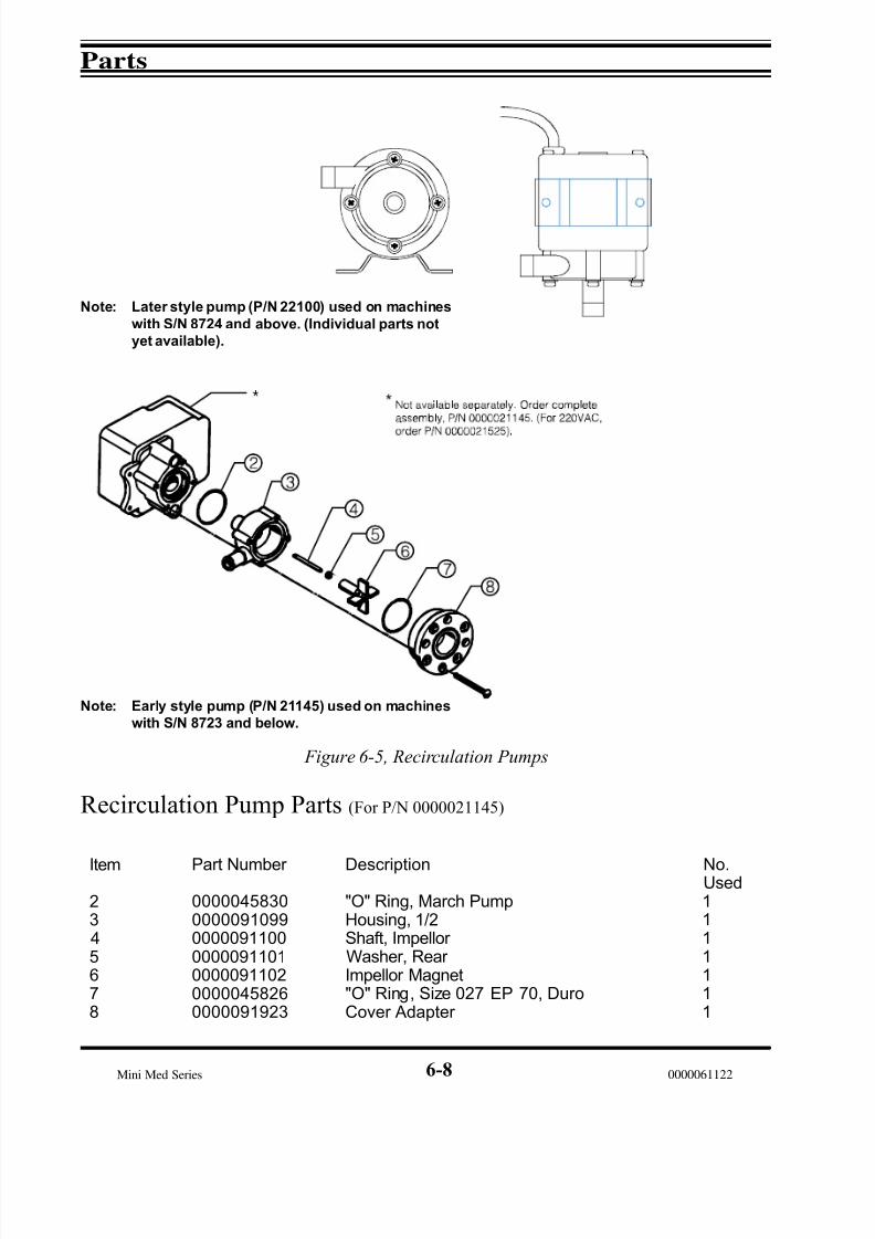
7/15/2019 Mini-medical 90
http://slidepdf.com/reader/full/mini-medical-90 106/132
Parts
Mini Med Series 00000611226-8
Figure 6-5, Recirculation Pumps
Recirculation Pump Parts (For P/N 0000021145)
Note: Early style pump (P/N 21145) used on machines
with S/N 8723 and below.
Note: Later style pump (P/N 22100) used on machines
with S/N 8724 and above. (Individual parts not
yet available).
Item
2345678
Part Number
0000045830000009109900000911000000091101000009110200000458260000091923
Description
"O" Ring, March PumpHousing, 1/2Shaft, Impellor Washer, Rear Impellor Magnet"O" Ring, Size 027 EP 70, DuroCover Adapter
No.Used1111111
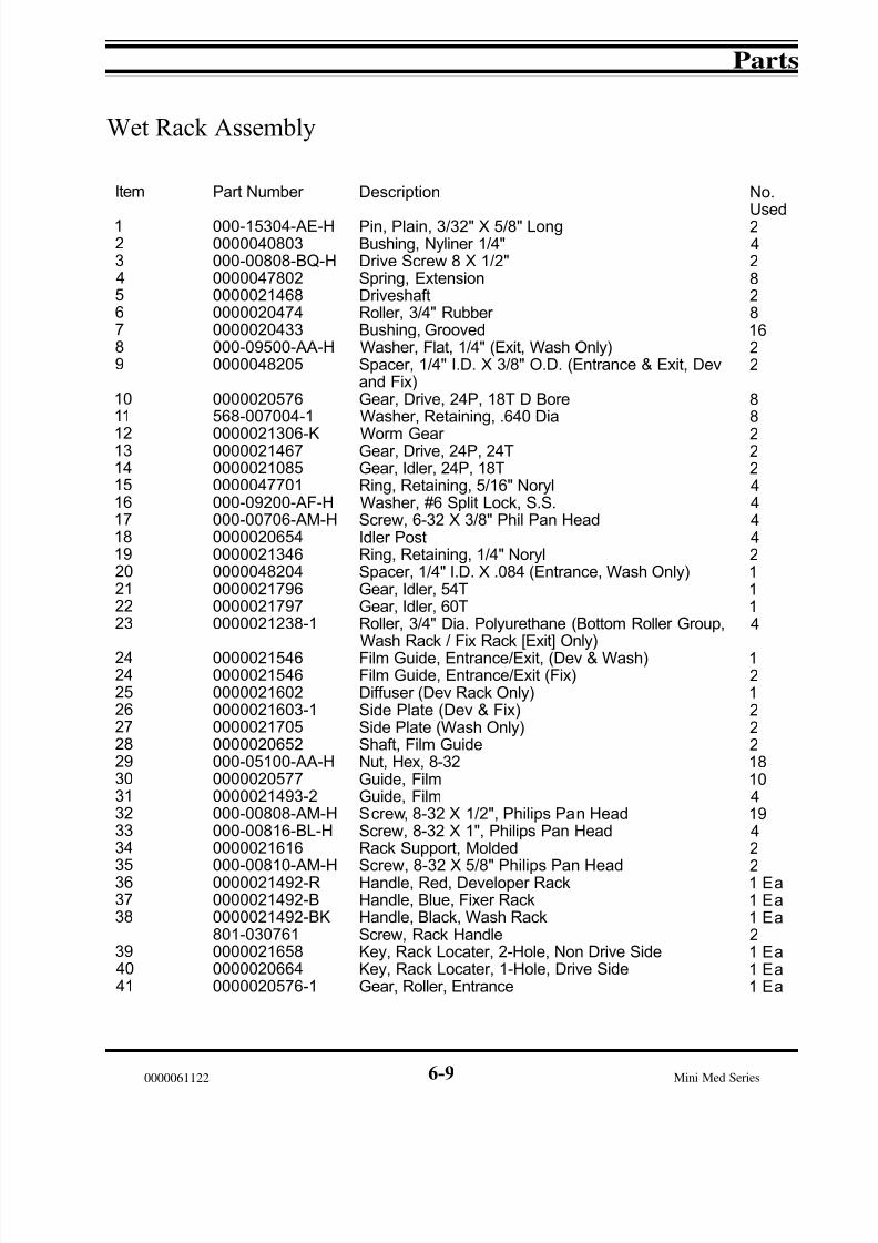
7/15/2019 Mini-medical 90
http://slidepdf.com/reader/full/mini-medical-90 107/132
Parts
Mini Med Series0000061122
Wet Rack Assembly
6-9
Item
123456789
1011
121314151617181920212223
242425262728293031323334
35363738
394041
Part Number
000-15304-AE-H0000040803000-00808-BQ-H0000047802000002146800000204740000020433000-09500-AA-H0000048205
0000020576568-007004-1
0000021306-K000002146700000210850000047701000-09200-AF-H000-00706-AM-H000002065400000213460000048204000002179600000217970000021238-1
0000021546000002154600000216020000021603-100000217050000020652000-05100-AA-H00000205770000021493-2000-00808-AM-H000-00816-BL-H0000021616
000-00810-AM-H0000021492-R0000021492-B0000021492-BK801-030761000002165800000206640000020576-1
Description
Pin, Plain, 3/32" X 5/8" LongBushing, Nyliner 1/4"Drive Screw 8 X 1/2"Spring, ExtensionDriveshaftRoller, 3/4" Rubber Bushing, GroovedWasher, Flat, 1/4" (Exit, Wash Only)Spacer, 1/4" I.D. X 3/8" O.D. (Entrance & Exit, Devand Fix)Gear, Drive, 24P, 18T D BoreWasher, Retaining, .640 Dia
Worm Gear Gear, Drive, 24P, 24TGear, Idler, 24P, 18TRing, Retaining, 5/16" NorylWasher, #6 Split Lock, S.S.Screw, 6-32 X 3/8" Phil Pan HeadIdler PostRing, Retaining, 1/4" NorylSpacer, 1/4" I.D. X .084 (Entrance, Wash Only)Gear, Idler, 54TGear, Idler, 60TRoller, 3/4" Dia. Polyurethane (Bottom Roller Group,Wash Rack / Fix Rack [Exit] Only)Film Guide, Entrance/Exit, (Dev & Wash)Film Guide, Entrance/Exit (Fix)Diffuser (Dev Rack Only)Side Plate (Dev & Fix)Side Plate (Wash Only)Shaft, Film GuideNut, Hex, 8-32Guide, FilmGuide, FilmScrew, 8-32 X 1/2", Philips Pan HeadScrew, 8-32 X 1", Philips Pan HeadRack Support, Molded
Screw, 8-32 X 5/8" Philips Pan HeadHandle, Red, Developer RackHandle, Blue, Fixer RackHandle, Black, Wash RackScrew, Rack HandleKey, Rack Locater, 2-Hole, Non Drive SideKey, Rack Locater, 1-Hole, Drive SideGear, Roller, Entrance
No.
Used2428281622
88
222444421114
121222181041942
21 Ea1 Ea1 Ea21 Ea1 Ea1 Ea
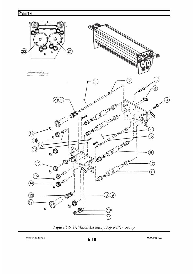
7/15/2019 Mini-medical 90
http://slidepdf.com/reader/full/mini-medical-90 108/132
Parts
Mini Med Series 0000061122
Figure 6-6, Wet Rack Assembly, Top Roller Group
6-10
1 2 3
4
3
1
5
6
7
6
20 9
8 9
1 0
1 1
1 2
1 3
1 4
1 5
1 6
1 7
1 8
1 9
41
Developer Rack - P/N 0000021764
Fixer Rack - P /N 0000021765Wa sh R ac k - P /N 0 000 02 17 66

7/15/2019 Mini-medical 90
http://slidepdf.com/reader/full/mini-medical-90 109/132
Parts
Mini Med Series0000061122
Figure 6-7, Wet Racks, Bottom Roller Group
Developer Rack - P/N 0000021764Fixer Rack - P/N 0000021765Wash Rack - P/N 0000021766
6-11

7/15/2019 Mini-medical 90
http://slidepdf.com/reader/full/mini-medical-90 110/132
Parts
Mini Med Series 0000061122
Figure 6-8, Wet Racks, Film Guide Group
Developer Rack - P/N 0000021764Fixer Rack - P/N 0000021765Wash Rack - P/N 0000021766
6-12
37 38
24
31
31
25
31
29
28
26
27
26
27
32
33
29
34
35
36
39
40
30

7/15/2019 Mini-medical 90
http://slidepdf.com/reader/full/mini-medical-90 111/132
Parts
Mini Med Series0000061122
6-13
Wash Rack Squeegee Roller Group
Figure 6-9, Wash Rack, Squeegee Roller Group
Exit
1
2
3
4
5
6
7
8
9
10
11
12
Item
1234
56789101112
Part Number
0000020261-4000002170400000213460000021759
000-15304-AE-H000002156200000408030000020261-50000021705000-00510-BR-H000-00514-BR-H000-09500-AA-H
Description
Rubber Roller, DrivenBracket, Squeegee Roller, ReworkedRetaining Ring, 1/4" NorylWorm Gear, Reworked
Pin, Plain, 3/32" Dia X 5/8" LongGear, Dryer DriveBushing, Nyliner, 1/4" DiaRoller, Driving, Long ShaftSide Plate, Modified, Wash RackScrew, #4 X 5/8" Self-Tap, PhillipsScrew, #4 X 7/8" Self-Tap, PhillipsWasher, 1/4 Flat, Small O.D.
No.Used1222
11412422

7/15/2019 Mini-medical 90
http://slidepdf.com/reader/full/mini-medical-90 112/132
Parts
Mini Med Series 0000061122
6-14
Dryer Assembly, Front Exit, P/N 0000021767
Item
123456
7891011
12131415161718192021222324
2526272829303132333435
36373839404143444546
Part Number
00000205720000047802568-00709500000216780000021493-20000021175-10000021175-200000215750000021726000002172800000889810000081993
575-0070280000037800568-0040950000021781000002173400000326760000021690000002167500000377600000020260-2000-01108-AW-R00000214630000021579
0000020417-10000021564086-00022800000215630000021797000002057500000206540000021086-300000216860000021730000002156900000216370000021771000002123100000216790000021493-10000041550-B0000021879000-00805-AQ-H000004770100000482800000021760
Description
Bushing, Spring Groove, 3/8"Spring, Extension, RacksSpacer, Film GuideBlock, Dryer AdjustmentGuide, 1-Piece Film, Dryer Lamp Assy, I.R., 14", 275W, 115VLamp Assy, I.R., 230VWire, Film GuideReflector AssyBracket, Air KnifeTerminal StripStrip Marker, MS601-0
Cover, Terminal StripThermostat, Dryer, High LimitHold Down, Temp Sensor, Dryer Sensor, Dryer Bracket, Connector Harness, Dryer Rack
Air Knife Assy, Rear Duct, PlenumJumper Roller, Rubber Screw, Thumb 1/4-20 X 1/2"Side PlatePivot Stud, Dryer
Bearing, Roller, 3/8"Gear, DrivingRing (Collar), Hub Tap, 8/32"Gear, Idler, 24P, 24TGear, 24P, 60TGear, Idler, 24P, 48TStud, Idler Gear, 24P, 24T
Air Knife Assy, FrontBracket, Blower Mount115V Dryer Fan Assy (2 Per Machine, 1 Per Dryer)230V Dryer Fan Assy (S/N 8677 and higher)Vertical DuctRoller AssyCoupler Duct, FanGuide, 1-Piece Film, Dryer Pin, Cotter, 1/16" X 1"Cover, Blower Motor, Mini-MedScrew, 8-32 X 5/16", Soc. SetClip, Retaining, 5/16" NorylSpacer, .200 I.D. X .375 I.D. X 1/4"Cover, Rear, Dryer, Mini-Med
No.
Used12642122102422
2121111122222
4221315611112611612541
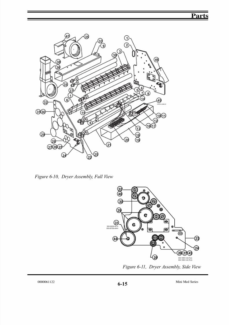
7/15/2019 Mini-medical 90
http://slidepdf.com/reader/full/mini-medical-90 113/132
Parts
Mini Med Series0000061122
6-15
Figure 6-10, Dryer Assembly, Full View
Figure 6-11, Dryer Assembly, Side View
1
2
3
45
7 8
9
10 11
12
13
14
18
1920
2224
15
16 17
21
33
252627
28
35
36
37
3839
25
32
31 30
35
1
6
29
00814-AM-H
6
41
46
45
23
000-09200-AF-H
000-00706-AM-H
000-10601-AC-R (2)
000-10601-AA-R (2)
29
30
31
32
40
44
24
28
26 27 43

7/15/2019 Mini-medical 90
http://slidepdf.com/reader/full/mini-medical-90 114/132
Parts
Mini Med Series 0000061122
6-16
Dryer Assembly, Rear Exit, P/N 0000021886
Item
123456
789
1011121314151617181920212223242526272829303132
3334
353637394043
Part Number
00000205720000047802568-00709500000216780000021493-20000021175-10000021175-2000002168400000482800000021728
0000088981000-00814-AM-H575-00702800000378000000021781000002173400000326760000021690000002167500000377600000020260-2
0000021018000002188700000215790000020417-10000021564086-00022800000215630000021365000002057500000206540000021086-30000021686
000004770100000215690000021637000-09200-AF-H000-00706-AM-H0000021231-10000021493-10000041550-B000-00805-AQ-H
Description
Bushing, Spring Groove, 3/8"Spring, Extension, RacksSpacer, Film GuideBlock, Dryer AdjustmentGuide, 1-Piece Film, Dryer Lamp Assy, I.R., 14", 275W, 115VLamp Assy, I.R., 230VWire, Film GuideSpacer, .200 I.D. X .375 O.D. X 1/4" LBracket, Air Knife
Terminal StripScrew, 8-32 X 7/8" Philips Pan HeadCover, Terminal StripThermostat, Dryer, High LimitSensor, Dryer Bracket, Connector Harness, Dryer Rack Air Knife Assy, Rear Duct, PlenumJumper Roller, Rubber
Gear, Idler, 24P, 36TSide Plate, Rear ExitPivot Stud, Dryer Bearing, Roller, 3/8"Gear, DrivingRing (Collar), Hub Tap, 8/32"Gear, Idler, 24P, 24TGear, 24P, 60TGear, Idler, 24P, 48TStud, Idler Gear, 24P, 24T Air Knife Assy, Front
Clip, Retaining, 5/16", NorylDryer Fan Assy (2 Per Machine, 1 Per Dryer)Dryer Fan Assy (S/N 8677 and higher)Washer, #6 Split LockScrew, 6-32 X 3/8" Philips Pan HeadRoller AssyGuide, 1-Piece Film, Dryer Pin, Cotter, 1/16" X 1"Screw, 8-32 X 5/16", Soc. Set
No.Used1264212
124424211111122
122422131561
51
46162

7/15/2019 Mini-medical 90
http://slidepdf.com/reader/full/mini-medical-90 115/132
Parts
Mini Med Series0000061122
6-17
Figure 6-12, Dryer Assembly, Rear Exit, Full View
Figure 6-13, Dryer Assembly, Rear Exit, Side View

7/15/2019 Mini-medical 90
http://slidepdf.com/reader/full/mini-medical-90 116/132
Parts
Mini Med Series 0000061122
6-18
Plumbing Schematic, (Figure 6-14)
Item
123456789101112131415161718192021
22232425262728293031
Part Number
0000035316000002148300000215070000021145000002110100000209950000020995-10000021436000002190400000215690000021637000002190300000414050000046251-C800-0703910000049008000004901300000218800000021848-10000021848-20000021869
000002185100000872200000046243-B0000046191-E0000046303-C00000210510000021701000002170000000414490000041450
Description
P.C.B Assy, Main HarnessMotor, Main Drive, (115VAC/230VAC-60Hz)Motor, Main Drive, (230VAC/50Hz)Pump, Recirculation, (115VAC)Pump, Recirculation, (230VAC)Pump, Replenisher, (115VAC)Pump, Replenisher, (230VAC)Tee Fitting, Rubber Clamp, SNP 22Fan Assy, Lower, (115VAC)Fan Assy, Lower, (230VAC)Nipple, Heat Exchanger Clamp, Hose, Worm Gear Elbow, 1/2" Barb X 1/2" BarbClamp, SNP 28Valve, Solenoid, 115VACValve, Solenoid, 230VACJacket, Heat Exchanger Heater, 500W, 115VACHeater, 550W, 230VACSensor Assy, Overtemp Safety
Bracket, Heater MountingValve, Drain, Specialty FNElbow, 90Deg, 1/4 FPT X 1/4 FPTNipple, 1/4 MPT X 3" PVCSpring, Replenisher Pump MountHanger, Replenisher PumpClamp, Drain PanelDrain PanelClamp, SNP 12 (Not Shown)Clamp, SNP 14 (Not Shown)
No.Used1112222221121232111111
13338411116
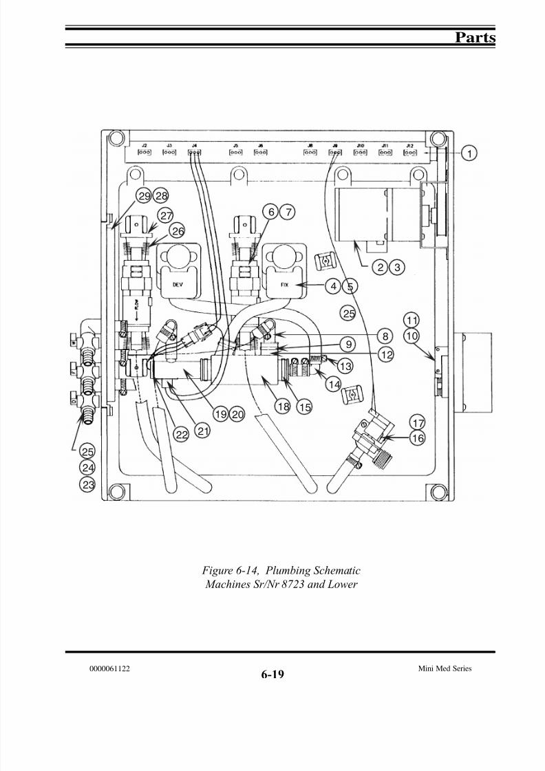
7/15/2019 Mini-medical 90
http://slidepdf.com/reader/full/mini-medical-90 117/132
Parts
Mini Med Series0000061122
Figure 6-14, Plumbing Schematic
Machines Sr/Nr 8723 and Lower
6-19
1
2 3
4 5
6 7
89
10
11
19
13
14
15
16
17
25
24
23
26
27
29 28
25
12
1820
2122
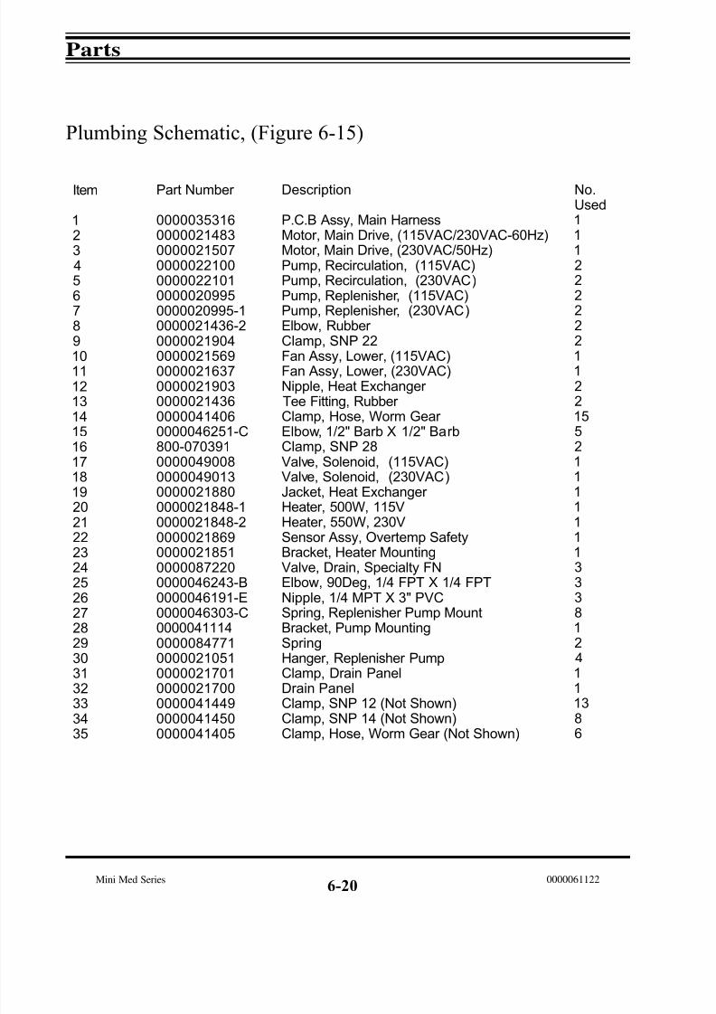
7/15/2019 Mini-medical 90
http://slidepdf.com/reader/full/mini-medical-90 118/132
Parts
Mini Med Series 0000061122
Plumbing Schematic, (Figure 6-15)
6-20
Item
123456789
1011121314151617181920212223242526272829303132
333435
Part Number
0000035316000002148300000215070000022100000002210100000209950000020995-10000021436-20000021904
000002156900000216370000021903000002143600000414060000046251-C800-0703910000049008000004901300000218800000021848-10000021848-20000021869000002185100000872200000046243-B0000046191-E0000046303-C00000411140000084771000002105100000217010000021700
000004144900000414500000041405
Description
P.C.B Assy, Main HarnessMotor, Main Drive, (115VAC/230VAC-60Hz)Motor, Main Drive, (230VAC/50Hz)Pump, Recirculation, (115VAC)Pump, Recirculation, (230VAC)Pump, Replenisher, (115VAC)Pump, Replenisher, (230VAC)Elbow, Rubber Clamp, SNP 22
Fan Assy, Lower, (115VAC)Fan Assy, Lower, (230VAC)Nipple, Heat Exchanger Tee Fitting, Rubber Clamp, Hose, Worm Gear Elbow, 1/2" Barb X 1/2" BarbClamp, SNP 28Valve, Solenoid, (115VAC)Valve, Solenoid, (230VAC)Jacket, Heat Exchanger Heater, 500W, 115VHeater, 550W, 230V
Sensor Assy, Overtemp SafetyBracket, Heater MountingValve, Drain, Specialty FNElbow, 90Deg, 1/4 FPT X 1/4 FPTNipple, 1/4 MPT X 3" PVCSpring, Replenisher Pump MountBracket, Pump MountingSpringHanger, Replenisher PumpClamp, Drain PanelDrain Panel
Clamp, SNP 12 (Not Shown)Clamp, SNP 14 (Not Shown)Clamp, Hose, Worm Gear (Not Shown)
No.Used111222222
1122155211111
113338124111386
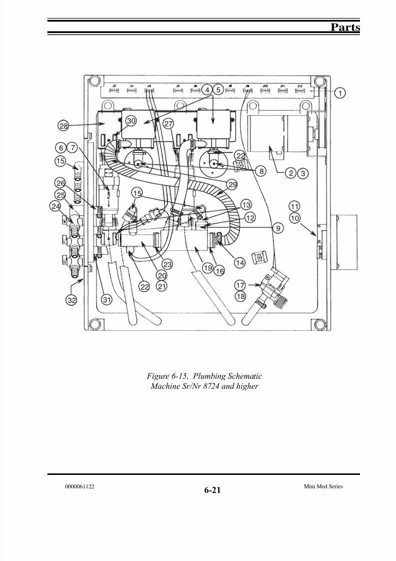
7/15/2019 Mini-medical 90
http://slidepdf.com/reader/full/mini-medical-90 119/132
Parts
Mini Med Series0000061122
6-21
Figure 6-15, Plumbing Schematic
Machine Sr/Nr 8724 and higher
1
2 3
4 5
6 7
27
12
13
14
15
16
18
19
30
26
22
9
29
28
8
32
10
11
15
17
20
2122
23
25
24
31

7/15/2019 Mini-medical 90
http://slidepdf.com/reader/full/mini-medical-90 120/132
Parts
Mini Med Series 0000061122
6-22
Notes:

7/15/2019 Mini-medical 90
http://slidepdf.com/reader/full/mini-medical-90 121/132
AFP Mini-Medical
X-Ray Film Processors
- General Index -
Section 0 - Safety Information
Section 1 - Introduction
Section 2 - Installation
Section 3 - Operation
Section 4 - Maintenance
Section 5 - Service
Section 6 - Parts
Section 7 - Accessories
0000061122
Section 7 Accessories

7/15/2019 Mini-medical 90
http://slidepdf.com/reader/full/mini-medical-90 122/132
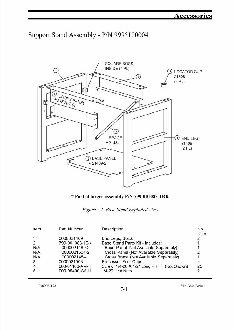
7/15/2019 Mini-medical 90
http://slidepdf.com/reader/full/mini-medical-90 123/132
Accessories
Mini Med Series0000061122
7-1
Support Stand Assembly - P/N 9995100004
C R O S S P AN E L2 15 0 4 - 2 ( 2 )
BASE PANEL
21489-2
21508
(4 PL)
LOCATOR CUP
SQUARE BOSS
INSIDE (4 PL)
(2 PL)
END LEG
21409
BRACE
21484
3
2
1
1
2
2
2
*
*
*
Figure 7-1, Base Stand Exploded View
Item
12N/AN/AN/A345
Part Number
0000021409799-001083-1BK
0000021489-20000021504-20000021484
0000021508000-01108-AM-H000-05400-AA-H
Description
End Legs, BlackBase Stand Parts Kit - Includes:
Base Panel (Not Available Separately)Cross Panel (Not Available Separately)Cross Brace (Not Available Separately)
Processor Foot CupsScrew, 1/4-20 X 1/2" Long P.P.H. (Not Shown)1/4-20 Hex Nuts
No.Used211214252
* Part of larger assembly P/N 799-001083-1BK

7/15/2019 Mini-medical 90
http://slidepdf.com/reader/full/mini-medical-90 124/132
Accessories
Mini Med Series 0000061122
Support Stand, Continued
These instructions cover assembly of the support stand used for allAFP Mini-Medical Series processors.
7-2
A
B
B
C
D
D
E
1. Assemble the Base Panel (Item A) to both End Legs (Item B) usingsix (6) of the 1/2" Philips screws provided. Do not tighten.
2. Hang the Cross Panels (Item D) over the square bosses on the End Legs
(Item B) and secure with four (4) Philips screws, one on each boss.
3. Determine the positions of the Locator Cups (Item C) depending onwhether it is to be a Standard or Right/Left Side installation (refer tothe illustrations on the next page). Attach the Locator Cups (Item C) anduse four (4) additional Philips screws to finish attaching the Cross Panels.
4. Attach the Cross Brace (Item E) between one of the holes common tothe Cross Panel and the square boss and one of the threaded holes inthe flange of the Base Panel. Tighten all screws.

7/15/2019 Mini-medical 90
http://slidepdf.com/reader/full/mini-medical-90 125/132
Accessories
Mini Med Series0000061122
7-3
Standard InstallationChemical tank access is fromfront of processor. Four (4) cupsscrewed on inboard top leg holes
Left Side InstallationChemical tank access is fromthe left side of processor. Two (2)cups are screwed on the outboardtop leg holes (at the front of the processor). Two (2) cups aremounted on the open slots on thecross panel using the screws and nuts
provided.
Right Side InstallationChemical tank access is fromthe right side of processor. Two (2)cups are screwed on the outboardtop leg holes (at the front of the processor). Two (2) cups aremounted on the open slots on thecross panel using the screws and nuts provided.

7/15/2019 Mini-medical 90
http://slidepdf.com/reader/full/mini-medical-90 126/132
Accessories
Mini Med Series 0000061122
Side Mount Drain Manifold Kit
The Side Plumbing Kit, p/n 9992305002, allows the re- positioning of the front mounted plumbing manifold toeither right or left side of a Mini-Medical processor.
1) Following the dimensions on the illustration be-low, drill four (4) 3/16" holes in the right or left
side of the processor for the manifold brackets.
2) Remove the original plumbing manifold from thefront of the processor (2 screws).
3) Carefully re-route the hoses to allow the plumbingmanifold to be relocated to the right or left side of the processor. NOTE: It may be necessary to remove andthen reconnect one or more of the hoses from the man-ifold during this process to obtain the best routingwithout kinking the hoses.
4) Install the plumbing manifold into the manifold
bracket on the side of the processor selected. Check for leaks wlth water or chemicals.
5) Install the filler plate in the front opening.
6) After charging the processor, carefully inspect allconnections for leaks and proper drainage.
7-4
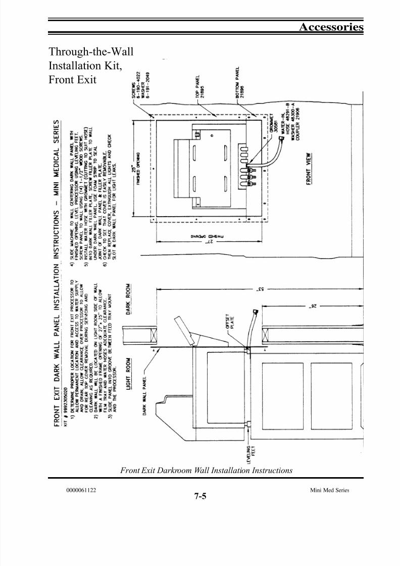
7/15/2019 Mini-medical 90
http://slidepdf.com/reader/full/mini-medical-90 127/132
Accessories
Mini Med Series0000061122
Front Exit Darkroom Wall Installation Instructions
Through-the-Wall
Installation Kit,
Front Exit
7-5

7/15/2019 Mini-medical 90
http://slidepdf.com/reader/full/mini-medical-90 128/132
Accessories
Mini Med Series 0000061122
Through-the-Wall
Installation Kit,
Rear Exit
Rear Exit Darkroom Wall Installation Instructions
7-6

7/15/2019 Mini-medical 90
http://slidepdf.com/reader/full/mini-medical-90 129/132
Accessories
Mini Med Series0000061122
Notes:
7-7

7/15/2019 Mini-medical 90
http://slidepdf.com/reader/full/mini-medical-90 130/132

7/15/2019 Mini-medical 90
http://slidepdf.com/reader/full/mini-medical-90 131/132

7/15/2019 Mini-medical 90
http://slidepdf.com/reader/full/mini-medical-90 132/132