mini cooper se. owner's manual
TRANSCRIPT
OWNER'S MANUAL.MINI COOPER SE.
LINK:CONTENT & A-Z
Online Edition for Part no. 01405A02680 - II/20

Online Edition for Part no. 01405A02680 - II/20
WELCOME TO MINI.
OWNER'S MANUAL.MINI COOPER SE.
Thank you for choosing a MINI.The more familiar you are with your vehicle, the better control you will haveon the road. We therefore strongly suggest:Read this Owner's Manual before starting off in your new MINI. Also use theIntegrated Owner's Manual in your vehicle. It contains important informationon vehicle operation that will help you make full use of the technical featuresavailable in your MINI. The manual also contains information designed toenhance operating reliability and road safety, and to contribute tomaintaining the value of your MINI.Any updates made after the editorial deadline can be found in the appendix ofthe printed Owner's Manual for the vehicle.Get started now. We wish you driving fun and inspiration with your MINI.
3Online Edition for Part no. 01405A02680 - II/20

TABLE OF CONTENTS
Navigation, Entertainment and Communication can be called up via theIntegrated Owner's Manual in the vehicle.
NOTESInformation.............................................................................................................................. 6
QUICK REFERENCEEntering.................................................................................................................................. 16
Set-up and use.......................................................................................................................19
On the road............................................................................................................................ 23
AT A GLANCECockpit.................................................................................................................................... 32
Central Information Display (CID)..................................................................................36
Voice activation system.................................................................................................... 44
General settings................................................................................................................... 48
Owner's Manual media.......................................................................................................60
MINI eDRIVE........................................................................................................................62
Safety of the high-voltage system.................................................................................. 65
CONTROLSOpening and closing........................................................................................................... 66
Seats, mirrors, and steering wheel.................................................................................85
Transporting children safely............................................................................................ 95
Driving..................................................................................................................................100
Displays................................................................................................................................ 118
Lights.................................................................................................................................... 135
Safety.....................................................................................................................................141
Driving stability control systems.................................................................................162
Driving comfort................................................................................................................. 167
4Online Edition for Part no. 01405A02680 - II/20

Climate control...................................................................................................................180
Interior equipment............................................................................................................187
Storage compartments.....................................................................................................198
Cargo area............................................................................................................................201
DRIVING TIPSThings to remember when driving.............................................................................. 208
Increasing range................................................................................................................212
MOBILITYCharging the vehicle........................................................................................................ 218
Wheels and tires................................................................................................................227
Engine compartment........................................................................................................243
Coolant..................................................................................................................................246
Maintenance....................................................................................................................... 248
Replacing components.................................................................................................... 250
Breakdown assistance..................................................................................................... 256
Care........................................................................................................................................262
REFERENCETechnical data.................................................................................................................... 268
Appendix..............................................................................................................................270
Everything from A to Z....................................................................................................272
© 2020 Bayerische Motoren WerkeAktiengesellschaftMunich, GermanyReprinting, including excerpts, only with the written consent of BMW AG, Munich.US English ID5 II/20, 03 20 490Printed on environmentally friendly paper, bleached without chlorine, suitable for recycling.
5Online Edition for Part no. 01405A02680 - II/20

Information
Using this Owner's Manual
OrientationThe fastest way to find information on aparticular topic is by using the index.
An initial overview of the vehicle is pro-vided in the first chapter.
Updates made after the editorialdeadlineDue to updates after the editorial deadline,differences may exist between the printedOwner's Manual and the Integrated Owner'sManual in the vehicle.
Notes on updates can be found in the ap-pendix of the printed Owner's Manual forthe vehicle.
Owner's Manual for Navigation,Entertainment, CommunicationThe Owner's Manual for Navigation, Enter-tainment, and Communication can be ob-tained as a printed book from the servicecenter.
The topics are also discussed in theIntegrated Owner's Manual in the vehicle.
Additional sources of informa-tion
Service centerA service center will be glad to answerquestions at any time.
InternetVehicle information and general informa-tion on MINI, e.g., on technology, are availa-ble on the Internet: www.miniusa.com.
Integrated Owner's Manual in thevehicleThe Integrated Owner's Manual specificallydescribes features and functions found inthe vehicle. The Integrated Owner's Manualcan be displayed on the Control Display. Ad-ditional information, refer to page 60.
MINI Motorer’s Guide appThe app specifically describes features andfunctions found in the vehicle. The app canbe displayed on smartphones and tablets.
MINI Motorer’s Guide WebDriver’s Guide Web shows the most suita-ble information for the selected vehicle. Ifpossible, only equipment and functions thatare actually installed in the vehicle will beexplained. Driver’s Guide Web can be dis-played in any current browser.
Symbols and displays
Symbols in the Owner's Manual
Symbol Meaning
Precautions that must befollowed in order to avoid thepossibility of injury to yourselfand to others as well as seriousdamage to the vehicle.
Measures that can be taken tohelp protect the environment.
Seite 6
NOTES Information
6Online Edition for Part no. 01405A02680 - II/20

Symbol Meaning
"..." Control Display texts used toselect individual functions.
›...‹ Verbal instructions to use withthe voice activation system..
››...‹‹ Responses generated by thevoice activation system.
Action stepsAction steps to be carried out are presentedas a numbered list. The steps must be car-ried out in the defined order.
1. First action step.
2. Second action step.
EnumerationsEnumerations without mandatory order oralternative possibilities are presented as alist with bullet points.
– First possibility.
– Second possibility.
Symbols on vehicle components This symbol on a vehicle component
indicates that further information on thecomponent is available in the Owner'sManual.
The symbols on parts of the vehicle indicatethat incorrect use of high-voltage equip-ment or of orange-colored high-voltage
components results in the risk of life-threat-ening injury from electric shock.
Vehicle features and options
This Owner's Manual describes all modelsand all standard, country-specific and op-tional equipment that is offered in themodel series. Therefore, this Owner'sManual also describes and illustrates fea-tures and functions that are not available ina vehicle, for example because of the se-lected optional features or the country-spe-cific version.
This also applies to safety-related functionsand systems.
When using these functions and systems,the applicable laws and regulations must beobserved.
For any options and equipment not descri-bed in this Owner's Manual, refer to theSupplementary Owner's Manuals.
Your dealer’s service center is happy to an-swer any questions that you may haveabout the features and options applicable toyour vehicle.
Status of the Owner's Manual
Basic informationThe manufacturer of your vehicle pursues apolicy of constant development that is con-ceived to ensure that our vehicles continueto embody the highest quality and safetystandards. In rare cases, therefore, the fea-tures described in this Owner's Manual maydiffer from those in your vehicle.
Seite 7
Information NOTES
7Online Edition for Part no. 01405A02680 - II/20
Updates made after the editorialdeadlineDue to updates after the editorial deadline,differences may exist between the printedOwner's Manual and the Integrated Owner'sManual in the vehicle.
Notes on updates can be found in the ap-pendix of the printed Owner's Manual forthe vehicle.
For Your Own Safety
ManufacturerThe manufacturer of this MINI is Bayeri-sche Motoren Werke Aktionengesellschaft,BMW AG.
Intended useHeed the following when using the vehicle:
– Owner's Manual.
– Information on the vehicle. Do not re-move stickers.
– Technical vehicle data.
– The traffic, speed, and safety laws wherethe vehicle is driven.
– Vehicle documents and statutory docu-ments.
WarrantyYour vehicle is technically configured forthe operating conditions and registrationrequirements applying in the country offirst delivery, also known as homologation.If your vehicle is to be operated in a differ-ent country it might be necessary to adaptyour vehicle to potentially differing operat-ing conditions and registration require-ments. If your vehicle does not comply withthe homologation requirements in a certaincountry you may not be able to lodge war-ranty claims for your vehicle there. Further
information on warranty is available from aservice center.
Maintenance and repairsAdvanced technology, for instance the useof modern materials and high-performanceelectronics, requires suitable maintenanceand repair work.
The manufacturer of your vehicle recom-mends that you entrust corresponding pro-cedures to a MINI dealer’s service center. Ifyou choose to use another service facility,the manufacturer of your vehicle recom-mends use of a facility that performs work,e.g., maintenance and repair, according toMINI specifications with properly trainedpersonnel, referred to in the Owner'sManual as "another qualified service centeror repair shop".
If work is performed improperly, for in-stance maintenance and repair, there is arisk of subsequent damage and relatedsafety risks.
Improperly performed work on the vehiclepaint can lead to a failure or malfunction ofcomponents, e.g., the radar sensors, andthereby result in a safety risk.
Parts and accessoriesThe manufacturer of your vehicle recom-mends the use of parts and accessory prod-ucts approved by the manufacturer of theMINI.
Approved parts and accessories, and adviceon their use and installation are availablefrom a MINI dealer's service center.
MINI parts and accessories were tested bythe manufacturer of the MINI for theirsafety and suitability in MINI vehicles.
The manufacturer of your vehicle warrantsgenuine MINI parts and accessories.
The manufacturer of your vehicle does notevaluate whether each individual product
Seite 8
NOTES Information
8Online Edition for Part no. 01405A02680 - II/20

from another manufacturer can be usedwith MINI vehicles without presenting asafety hazard, even if a country-specific of-ficial approval was issued. The manufac-turer of your vehicle does not evaluatewhether these products are suitable forMINI vehicles under all usage conditions.
California Proposition 65 WarningFor vehicles sold in California, the law re-quires vehicle manufacturers to provide thefollowing warning:
Warning
Engine exhaust and a wide variety of Au-tomobile components and parts, includingcomponents found in the interior furnish-ings in a vehicle, contain or emit chemi-cals known to the State of California tocause cancer and birth defects and repro-ductive harm. In addition, certain fluidscontained in vehicles and certain productsof component wear contain or emit chemi-cals known to the State of California tocause cancer and birth defects or other re-productive harm. Battery posts, terminalsand related accessories contain lead andlead compounds. Batteries also containother chemicals known to the State of Cali-fornia to cause cancer. Wash your handsafter handling. Used engine oil containschemicals that have caused cancer in labo-ratory animals. Always protect your skinby washing thoroughly with soap and wa-ter. For more information go towww.P65Warnings.ca.gov/passenger-ve-hicle.
Warning
Operating, servicing and maintaining apassenger vehicle or off-highway motorvehicle can expose you to chemicals in-cluding engine exhaust, carbon monoxide,
phthalates, and lead, which are known tothe State of California to cause cancer andbirth defects or other reproductive harm.To minimize exposure, avoid breathing ex-haust, do not idle the engine except asnecessary, service your vehicle in a well-ventilated area and wear gloves or washyour hands frequently when servicingyour vehicle. For more information go towww.P65Warnings.ca.gov/passenger-ve-hicle.
Service and warrantyWe recommend that you read this publica-tion thoroughly. Your vehicle is covered bythe following warranties:
– New Vehicle Limited Warranty.
– Rust Perforation Limited Warranty.
– Federal Emissions System Defect War-ranty.
– Federal Emissions Performance War-ranty.
– California Emission Control System Lim-ited Warranty.
Detailed information about these warrantiesis listed in the Service and Warranty Infor-mation Booklet for US models or in the War-ranty and Service Guide Booklet for Cana-dian models.
Your vehicle has been specifically adaptedand designed to meet the particular operat-ing conditions and homologation require-ments in your country and continental re-gion in order to deliver the full drivingpleasure while the vehicle is operated underthose conditions. If you wish to operateyour vehicle in another country or region,you may be required to adapt your vehicleto meet different prevailing operating con-ditions and homologation requirements.You should also be aware of any applicablewarranty limitations or exclusions for suchcountry or region. In such case, please con-
Seite 9
Information NOTES
9Online Edition for Part no. 01405A02680 - II/20
tact Customer Relations for further informa-tion.
MaintenanceMaintain the vehicle regularly to sustainthe road safety, operational reliability andthe New Vehicle Limited Warranty.
Specifications for maintenance measures:
– MINI Maintenance system.
– Service and Warranty Information Book-let for US models.
– Warranty and Service Guide Booklet forCanadian models.
If the vehicle is not maintained or is im-properly maintained, this could result in se-rious damage to the vehicle. Such damage isnot covered by the MINI New Vehicle Lim-ited Warranty.
Refer to chapter engine oil change regard-ing recommended service intervals for oilchanges.
Data memory
General informationElectronic control devices are installed inthe vehicle. Electronic control units processdata they receive from vehicle sensors, self-generate or exchange with each other. Somecontrol units are necessary for the vehicleto function safely or provide assistance dur-ing driving, for instance driver assistancesystems. Furthermore, control units facili-tate comfort or infotainment functions.
Information about stored or exchanged datacan be requested from the manufacturer ofthe vehicle, in a separate booklet, for exam-ple.
Personal referenceEach vehicle is marked with a unique vehi-cle identification number. Depending on thecountry, the vehicle owner can be identifiedwith the vehicle identification number, li-cense plate and corresponding authorities.In addition, there are other options to trackdata collected in the vehicle to the driver orvehicle owner, for instance via utilizedservices.
Operating data in the vehicleControl units process data to operate the ve-hicle.
For example, this includes:
– Status messages for the vehicle and itsindividual components, e.g., wheel rota-tional speed, wheel speed, deceleration,transverse acceleration, engaged safetybelt indicator.
– Ambient conditions, e.g., temperature,rain sensor signals.
The processed data is only processed in thevehicle itself and generally volatile. Thedata is not stored beyond the operating pe-riod.
Electronic components, e.g. control unitsand ignition keys, contain components forstoring technical information. Informationabout the vehicle condition, component us-age, maintenance requirements events orfaults can be stored temporarily or perma-nently.
This information generally records the stateof a component, a module, a system, or theenvironment, for instance:
– Operating states of system components,for instance, fill levels, tire inflationpressure, battery status.
– Malfunctions and faults in importantsystem components, for instance lightsand brakes.
Seite 10
NOTES Information
10Online Edition for Part no. 01405A02680 - II/20
– Responses by the vehicle to special sit-uations such as airbag deployment orengagement of the driving stability con-trol systems.
– Information on vehicle-damagingevents.
The data is required to perform the controlunit functions. Furthermore, it also servesto recognize and correct malfunctions, andhelps the vehicle manufacturer to optimizevehicle functions.
The majority of this data is volatile and isonly processed within the vehicle itself.Only a small share of the data is storedevent-related in event or fault memories.
When servicing, for instance during repairs,service processes, warranty cases, and qual-ity assurance measures, this technical infor-mation can be read out from the vehicle to-gether with the vehicle identificationnumber.
A dealer’s service center or another quali-fied service center or repair shop can readout the information. The socket for OBD On-board Diagnosis required by law in the ve-hicle is used to read out the data.
The data is collected, processed, and usedby the relevant organizations in the servicenetwork. The data documents technical con-ditions of the vehicle, helps with the identi-fication of the fault, compliance with war-ranty obligations and quality improvement.
Furthermore, the manufacturer has productmonitoring duties to meet in line with prod-uct liability law. To fulfill these duties, thevehicle manufacturer needs technical datafrom the vehicle. The data from the vehiclecan also be used to check customer claimsfor warranty and guaranty.
Fault and event memories in the vehicle canbe reset when a dealer’s service center oranother qualified service center or repairshop performs repair or servicing work.
Data entry and data transfer intothe vehicle
General informationDepending on the vehicle equipment, com-fort and individual settings can be stored inthe vehicle and modified or reset at anytime.
For example, this includes:
– Settings for the seat and steering wheelpositions.
– Suspension and climate control settings.
If necessary, data can be transferred to theentertainment and communication systemof the vehicle, for instance via smartphone.
This includes the following depending onthe respective equipment:
– Multimedia data such as music, films orphotos for playback in an integratedmultimedia system.
– Address book data for use in conjunc-tion with an integrated hands-free sys-tem or an integrated navigation system.
– Entered navigation destinations.
– Data on the use of Internet services.
This data can be stored locally in the vehicleor is found on a device that has been con-nected to the vehicle, e.g., a smartphone,USB stick or MP3 player. If this data isstored in the vehicle, it can be deleted atany time.
This data is only transmitted to third partiesupon personal request as part of the use ofonline services. The transmission dependson the selected settings for the use of theservices.
Incorporation of mobile devicesDepending on the vehicle equipment, mo-bile devices connected to the vehicle, for in-stance smartphones, can be controlled viathe vehicle control elements.
Seite 11
Information NOTES
11Online Edition for Part no. 01405A02680 - II/20

The sound and picture from the mobile de-vice can be played back and displayedthrough the multimedia system. Certain in-formation is transferred to the mobile de-vice at the same time. Depending on thetype of incorporation, this includes, for in-stance position data and other general vehi-cle information. This optimizes the way inwhich selected apps, for instance navigationor music playback, work.
There is no further interaction between themobile device and the vehicle, such as ac-tive access to vehicle data.
How the data will be processed further isdetermined by the provider of the particularapp being used. The extent of the possiblesettings depends on the respective app andthe operating system of the mobile device.
Services
General informationIf the vehicle has a wireless network con-nection, this enables data to be exchangedbetween the vehicle and other systems. Thewireless network connection is realized viaan in-vehicle transmitter and receiver unitor via personal mobile devices brought intothe vehicle, for instance smartphones. Thiswireless network connection enables 'onlinefunctions' to be used. These include onlineservices and apps supplied by the vehiclemanufacturer or by other providers.
Services from the vehiclemanufacturerWhere online services from the vehiclemanufacturer are concerned, the corre-sponding functions are described in the ap-propriate place, for instance the Owner'sManual or manufacturer's website. The rele-vant legal information pertaining to dataprotection is provided there too. Personaldata may be used to perform online serv-ices. Data is exchanged over a secure con-
nection, for instance with the IT systems ofthe vehicle manufacturer intended for thispurpose.
Any collection, processing, and use of per-sonal data above and beyond that needed toprovide the services must always be basedon a legal permission, contractual arrange-ment or consent. It is also possible to acti-vate or deactivate the data connection as awhole. That is, with the exception of func-tions and services required by law such asAssist systems.
Services from other providersWhen using online services from other pro-viders, these services are the responsibilityof the relevant provider and subject to theirdata privacy conditions and terms of use.The vehicle manufacturer has no influenceon the content exchanged during this proc-ess. Information on the way in which per-sonal data is collected and used in relationto services from third parties, the scope ofsuch data, and its purpose, can be obtainedfrom the relevant service provider.
Event Data Recorder EDR
This vehicle is equipped with an event datarecorder EDR. The main purpose of an EDRis to record, in certain crash or near crash-like situations, such as an air bag deploy-ment or hitting a road obstacle, data thatwill assist in understanding how a vehicle’ssystems performed. The EDR is designed torecord data related to vehicle dynamics andsafety systems for a short period of time,typically 30 seconds or less.
The EDR in this vehicle is designed to re-cord such data as:
– How various systems in your vehiclewere operating.
Seite 12
NOTES Information
12Online Edition for Part no. 01405A02680 - II/20
– Whether or not the driver and passen-ger safety belts were fastened.
– How far, if at all, the driver was depress-ing the accelerator and/or brake pedal.
– How fast the vehicle was traveling.
This data can help provide a better under-standing of the circumstances in whichcrashes and injuries occur.
EDR data is recorded by your vehicle only ifa nontrivial crash situation occurs; no datais recorded by the EDR under normal driv-ing conditions and no personal data, for in-stance name, gender, age, and crash loca-tion, are recorded.
However, other parties, such as law enforce-ment, could combine the EDR data with thetype of personally identifying data routinelyacquired during a crash investigation.
To read data recorded by an EDR, specialequipment is required, and access to the ve-hicle or the EDR is needed. In addition tothe vehicle manufacturer, other parties,such as law enforcement, that have the spe-cial equipment, can read the information ifthey have access to the vehicle or the EDR.
Vehicle identification number
Engine compartment
The vehicle identification number can befound in the engine compartment, on theright-hand side of the vehicle.
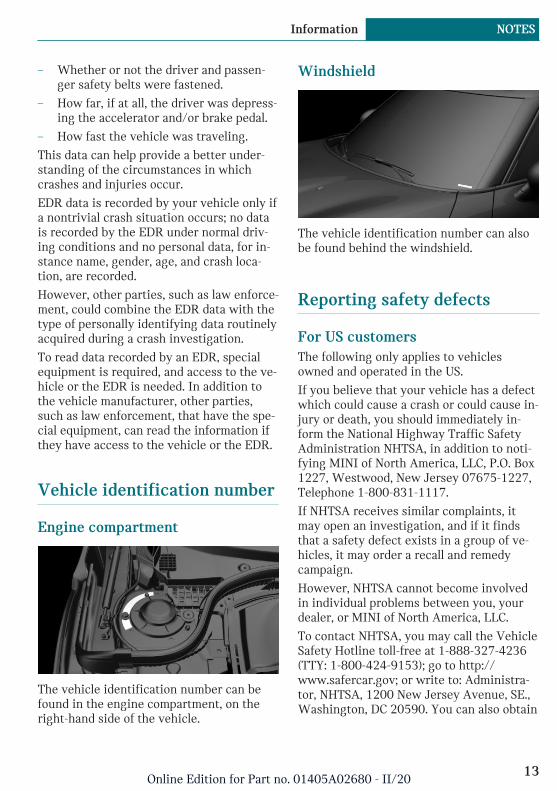
Windshield
The vehicle identification number can alsobe found behind the windshield.
Reporting safety defects
For US customersThe following only applies to vehiclesowned and operated in the US.
If you believe that your vehicle has a defectwhich could cause a crash or could cause in-jury or death, you should immediately in-form the National Highway Traffic SafetyAdministration NHTSA, in addition to noti-fying MINI of North America, LLC, P.O. Box1227, Westwood, New Jersey 07675-1227,Telephone 1-800-831-1117.
If NHTSA receives similar complaints, itmay open an investigation, and if it findsthat a safety defect exists in a group of ve-hicles, it may order a recall and remedycampaign.
However, NHTSA cannot become involvedin individual problems between you, yourdealer, or MINI of North America, LLC.
To contact NHTSA, you may call the VehicleSafety Hotline toll-free at 1-888-327-4236(TTY: 1-800-424-9153); go to http://www.safercar.gov; or write to: Administra-tor, NHTSA, 1200 New Jersey Avenue, SE.,Washington, DC 20590. You can also obtain
Seite 13
Information NOTES
13Online Edition for Part no. 01405A02680 - II/20

other information about motor vehiclesafety from http://www.safercar.gov
For Canadian customersCanadian customers who wish to report asafety-related defect to Transport Canada,Defect Investigations and Recalls, may callthe toll-free hotline 1-800-333-0510. Youcan also obtain other information about mo-tor vehicle safety from http://www.tc.gc.ca/roadsafety.
Seite 14
NOTES Information
14Online Edition for Part no. 01405A02680 - II/20

Seite 15
Information NOTES
15Online Edition for Part no. 01405A02680 - II/20

Entering
Opening and closing
Buttons on the vehicle key
1 Unlocking
2 Locking
3 Unlocking the tailgate
4 Panic mode
Unlocking the vehiclePress the button on the vehicle key.
Depending on the settings, either only thedriver's door or all vehicle access points areunlocked.
If only the driver's door is unlocked, pressthe button on the vehicle key again to un-lock the other vehicle access points.
Press and hold the button on the ve-hicle key after unlocking.
The windows and the glass sunroof areopened, as long as the button on the vehiclekey is pressed.
Locking the vehiclePress the button on the vehicle key.
All vehicle access points are locked.
Buttons for the central lockingsystem
Overview
Buttons for the central locking system.
Locking
Pressing the button locks the vehi-cle if the front doors are closed.
Unlocking
Pressing the button unlocks the ve-hicle.
Panic modeYou can trigger the alarm system if you findyourself in a dangerous situation.
Press the button on the vehicle keyand hold for at least 3 seconds.
To switch off the alarm: press any button.
Comfort Access
ConceptThe vehicle can be accessed without operat-ing the vehicle key.
Carrying the vehicle key with you, e.g., inyour pants pocket, is sufficient.
Seite 16
QUICK REFERENCE Entering
16Online Edition for Part no. 01405A02680 - II/20
The vehicle automatically detects the vehi-cle key when it is in close proximity or inthe car's interior.
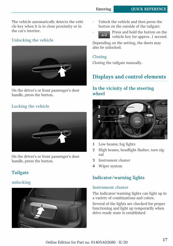
Unlocking the vehicle
On the driver's or front passenger's doorhandle, press the button.
Locking the vehicle
On the driver's or front passenger's doorhandle, press the button.
Tailgate
unlocking
– Unlock the vehicle and then press thebutton on the outside of the tailgate.
– Press and hold the button on thevehicle key for approx. 1 second.
Depending on the setting, the doors mayalso be unlocked.
ClosingClosing the tailgate manually.
Displays and control elements
In the vicinity of the steeringwheel
1 Low beams, fog lights
2 High beams, headlight flasher, turn sig-nal
3 Instrument cluster
4 Wiper system
Indicator/warning lights
Instrument clusterThe indicator/warning lights can light up ina variety of combinations and colors.
Several of the lights are checked for properfunctioning and light up temporarily whendrive-ready state is established.
Seite 17
Entering QUICK REFERENCE
17Online Edition for Part no. 01405A02680 - II/20
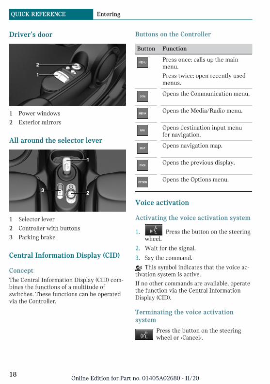
Driver's door
1 Power windows
2 Exterior mirrors
All around the selector lever
1 Selector lever
2 Controller with buttons
3 Parking brake
Central Information Display (CID)
ConceptThe Central Information Display (CID) com-bines the functions of a multitude ofswitches. These functions can be operatedvia the Controller.
Buttons on the Controller
Button Function
Press once: calls up the mainmenu.
Press twice: open recently usedmenus.
Opens the Communication menu.
Opens the Media/Radio menu.
Opens destination input menufor navigation.
Opens navigation map.
Opens the previous display.
Opens the Options menu.
Voice activation
Activating the voice activation system
1. Press the button on the steeringwheel.
2. Wait for the signal.
3. Say the command.
This symbol indicates that the voice ac-tivation system is active.
If no other commands are available, operatethe function via the Central InformationDisplay (CID).
Terminating the voice activationsystem
Press the button on the steeringwheel or ›Cancel‹.
Seite 18
QUICK REFERENCE Entering
18Online Edition for Part no. 01405A02680 - II/20
Set-up and use
Seats, mirrors, and steeringwheel
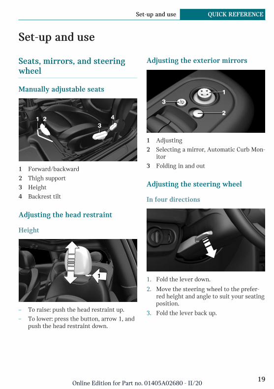
Manually adjustable seats
1 Forward/backward
2 Thigh support
3 Height
4 Backrest tilt
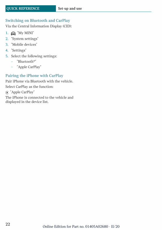
Adjusting the head restraint
Height
– To raise: push the head restraint up.
– To lower: press the button, arrow 1, andpush the head restraint down.
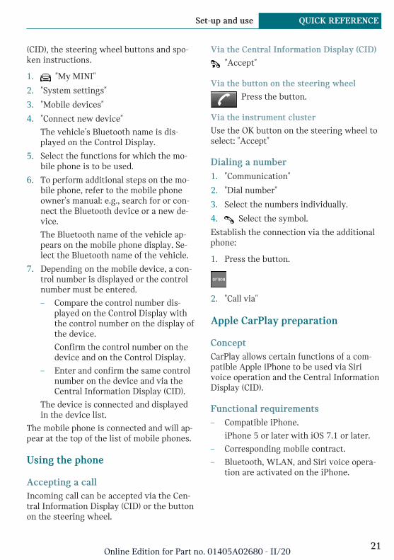
Adjusting the exterior mirrors
1 Adjusting
2 Selecting a mirror, Automatic Curb Mon-itor
3 Folding in and out
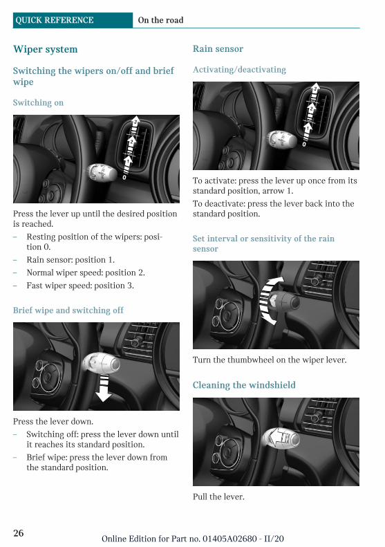
Adjusting the steering wheel
In four directions
1. Fold the lever down.
2. Move the steering wheel to the prefer-red height and angle to suit your seatingposition.
3. Fold the lever back up.
Seite 19
Set-up and use QUICK REFERENCE
19Online Edition for Part no. 01405A02680 - II/20

Entering the rear1. Pull lever up to the stop.
2. Fold backrest forward.
3. Push the seat forward.
Original position1. Push the seat back into the original po-
sition.
2. Fold back the backrest to lock the seat.
Infotainment
Radio
Control elements
1 Changing the waveband
2 Changing the entertainment source
3 Sound output on/off, volume
4 Changing the station/track
5 Programmable memory buttons
Navigation destination entry
Entering a destination via address
State/province
1. "Navigation"
2. "Enter address"
3. "State/Province?"
4. Select the country from the list.
Entering the address
The address can be entered in any order.
Example: entering the address via the town/city
1. "City/Postal code?"
2. Enter the town/city.
The list is narrowed down further witheach entry.
3. Select the symbol.
4. Select a town/city from the list.
5. If necessary, enter the street.
6. Select the street as you would the town/city.
7. If necessary, enter a house number.
8. Select the symbol.
9. Select a house number or range of housenumbers from the list.
Starting destination guidance"Start guidance"
If only the town/city was entered: destina-tion guidance is started to the town/citycenter.
Pairing the mobile phoneAfter the mobile phone is paired once withthe vehicle, the mobile phone can be oper-ated using the Central Information Display
Seite 20
QUICK REFERENCE Set-up and use
20Online Edition for Part no. 01405A02680 - II/20
(CID), the steering wheel buttons and spo-ken instructions.
1. "My MINI"
2. "System settings"
3. "Mobile devices"
4. "Connect new device"
The vehicle's Bluetooth name is dis-played on the Control Display.
5. Select the functions for which the mo-bile phone is to be used.
6. To perform additional steps on the mo-bile phone, refer to the mobile phoneowner's manual: e.g., search for or con-nect the Bluetooth device or a new de-vice.
The Bluetooth name of the vehicle ap-pears on the mobile phone display. Se-lect the Bluetooth name of the vehicle.
7. Depending on the mobile device, a con-trol number is displayed or the controlnumber must be entered.
– Compare the control number dis-played on the Control Display withthe control number on the display ofthe device.
Confirm the control number on thedevice and on the Control Display.
– Enter and confirm the same controlnumber on the device and via theCentral Information Display (CID).
The device is connected and displayedin the device list.
The mobile phone is connected and will ap-pear at the top of the list of mobile phones.
Using the phone
Accepting a callIncoming call can be accepted via the Cen-tral Information Display (CID) or the buttonon the steering wheel.
Via the Central Information Display (CID)
"Accept"
Via the button on the steering wheel
Press the button.
Via the instrument cluster
Use the OK button on the steering wheel toselect: "Accept"
Dialing a number1. "Communication"
2. "Dial number"
3. Select the numbers individually.
4. Select the symbol.
Establish the connection via the additionalphone:
1. Press the button.
2. "Call via"
Apple CarPlay preparation
ConceptCarPlay allows certain functions of a com-patible Apple iPhone to be used via Sirivoice operation and the Central InformationDisplay (CID).
Functional requirements– Compatible iPhone.
iPhone 5 or later with iOS 7.1 or later.
– Corresponding mobile contract.
– Bluetooth, WLAN, and Siri voice opera-tion are activated on the iPhone.
Seite 21
Set-up and use QUICK REFERENCE
21Online Edition for Part no. 01405A02680 - II/20
Switching on Bluetooth and CarPlayVia the Central Information Display (CID):
1. "My MINI"
2. "System settings"
3. "Mobile devices"
4. "Settings"
5. Select the following settings:
– "Bluetooth®"
– "Apple CarPlay"
Pairing the iPhone with CarPlayPair iPhone via Bluetooth with the vehicle.
Select CarPlay as the function:
"Apple CarPlay"
The iPhone is connected to the vehicle anddisplayed in the device list.
Seite 22
QUICK REFERENCE Set-up and use
22Online Edition for Part no. 01405A02680 - II/20

On the road
Driving
Drive-ready state
General informationWhen drive-ready state is switched on, thevehicle is operational.
All vehicle systems are ready for operation.
Most of the indicator/warning lights in theinstrument cluster light up for a variedlength of time.
Activated drive-ready state is the equiva-lent of a running engine in conventional ve-hicles. Deactivated drive-ready state isequivalent to switching the engine off.
To save battery power when parking, switchoff drive-ready state and any unnecessaryelectronic systems/power consumers.
Drive-ready state is switched off automati-cally:
– When you lock the vehicle while lowbeams are switched on.
– If the charge state of the batteries islow.
– When opening or closing the driverdoor, if the driver's safety belt is un-buckled and the low beams are switchedoff.
– While the driver's safety belt is unbuck-led with driver's door open and lowbeams off.
After the driver's door is opened or closedor the driver's safety belt is released, theradio-ready state remains active.
Start/Stop buttonPressing the Start/Stop buttonswitches standby state on oroff.
Drive-ready state is switchedon when you depress the
brake pedal while pressing the Start/Stopbutton.
Switching on drive-ready state1. Close the driver's door.
2. Depress the brake pedal.
3. Press the Start/Stop button.
Drive-ready state is switched on.
DisplaysREADY indicates drive-readystate.
Drive-ready state in detail
RequirementsDriving is possible under the following con-ditions:
– The high-voltage battery is sufficientlycharged.
– The driver's door is closed.
– Charging cable is detached.
Driving away1. Switch on drive-ready state.
2. Apply the brake and engage the selectorlever in position D or R.
Seite 23
On the road QUICK REFERENCE
23Online Edition for Part no. 01405A02680 - II/20

3. Release the parking brake.
4. Depress the accelerator pedal to driveoff.
Accelerator pedal positions
1 Deceleration
2 Coasting
3 Acceleration or constant speed: ePO-WER
Engaging the gear– Interlock: the selector lever position P
can be exited only with drive-readystate engaged.
– Shift lock: with the vehicle stationary,press on the brake pedal before shiftingout of P or N; otherwise, the shift com-mand will not be executed.
– Shift lock: before shifting out of P, re-move the charging cable from the vehi-cle; otherwise, the shift command willnot be executed.
Engaging N, D, R
Move the selector lever in the desired direc-tion.
Engaging P
Apply brake and press button P.
Parking brake
SettingPull the switch when the vehicle isstationary.
The LED and indicator light light up.
ReleasingPress the switch while stepping on thebrake pedal or selector lever position P
is set.
The LED and indicator light go out.
The parking brake is released.
Seite 24
QUICK REFERENCE On the road
24Online Edition for Part no. 01405A02680 - II/20

High beams, headlight flasher, turnsignal, roadside parking light
High beams, headlight flasher
Push the lever forward or pull it backward.
– High beams on, arrow 1.
The high beams light up when the lowbeams are switched on.
– High beams off/headlight flasher, ar-row 2.
Turn signal
– On: press the lever past the resistancepoint.
– Off: lightly tap the lever to the resist-ance point.
– Off: press the lever past the resistancepoint in the opposite direction.
– Triple turn signal activation: lightly tapthe lever up or down.
– Brief signaling: press the lever to the re-sistance point and hold it there for aslong as you want the turn signal to flash.
Canada: roadside parking light
To illuminate the vehicle on one side.
– On: with the standby state switched off,press the lever either up or down pastthe resistance point for approx. 2 sec-onds.
– Off: briefly press the lever to the resist-ance point in the opposite direction.
Lights and lighting
Light functions
Symbol Function
Front fog lights.
Automatic headlight control.
Lights off.
Daytime running lights.
Parking lights.
Low beams.
Instrument lighting.
Seite 25
On the road QUICK REFERENCE
25Online Edition for Part no. 01405A02680 - II/20
Wiper system
Switching the wipers on/off and briefwipe
Switching on
Press the lever up until the desired positionis reached.
– Resting position of the wipers: posi-tion 0.
– Rain sensor: position 1.
– Normal wiper speed: position 2.
– Fast wiper speed: position 3.
Brief wipe and switching off
Press the lever down.
– Switching off: press the lever down untilit reaches its standard position.
– Brief wipe: press the lever down fromthe standard position.
Rain sensor
Activating/deactivating
To activate: press the lever up once from itsstandard position, arrow 1.
To deactivate: press the lever back into thestandard position.
Set interval or sensitivity of the rainsensor
Turn the thumbwheel on the wiper lever.
Cleaning the windshield
Pull the lever.
Seite 26
QUICK REFERENCE On the road
26Online Edition for Part no. 01405A02680 - II/20
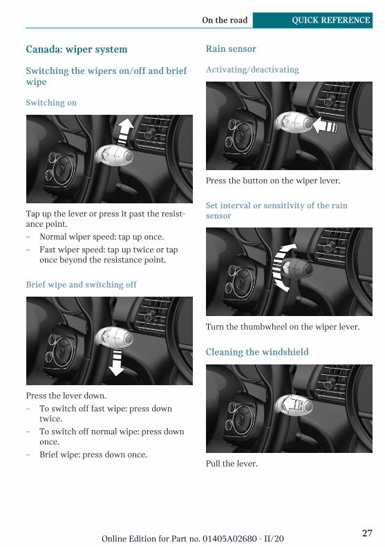
Canada: wiper system
Switching the wipers on/off and briefwipe
Switching on
Tap up the lever or press it past the resist-ance point.
– Normal wiper speed: tap up once.
– Fast wiper speed: tap up twice or taponce beyond the resistance point.
Brief wipe and switching off
Press the lever down.
– To switch off fast wipe: press downtwice.
– To switch off normal wipe: press downonce.
– Brief wipe: press down once.
Rain sensor
Activating/deactivating
Press the button on the wiper lever.
Set interval or sensitivity of the rainsensor
Turn the thumbwheel on the wiper lever.
Cleaning the windshield
Pull the lever.
Seite 27
On the road QUICK REFERENCE
27Online Edition for Part no. 01405A02680 - II/20
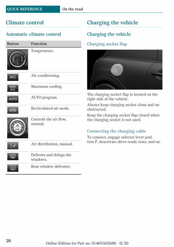
Climate control
Automatic climate control
Button Function
Temperature.
Air conditioning.
Maximum cooling.
AUTO program.
Recirculated-air mode.
Controls the air flow,manual.
Air distribution, manual.
Defrosts and defogs thewindows.
Rear window defroster.
Charging the vehicle
Charging the vehicle
Charging socket flap
The charging socket flap is located on theright side of the vehicle.
Always keep charging socket clean and un-obstructed.
Keep the charging socket flap closed whenthe charging socket is not used.
Connecting the charging cableTo connect, engage selector lever posi-tion P, deactivate drive-ready state, and un-
Seite 28
QUICK REFERENCE On the road
28Online Edition for Part no. 01405A02680 - II/20

lock the vehicle. Set the parking brake, ifneeded.
1. Tap on the charging socket flap, arrow.The charging socket flap opens.
2. Remove the charging socket lid, arrow.
3. Remove the cover of the charging cableplug, if needed.
4. Connect Level 1 charging cable to thehousehold socket or Level 2 chargingcable to the port on the charging station.
5. Insert the appropriate charging cableplug, and push it in until it engages.
When charging at a charging station, followthe instructions at the charging station.
RemovingWhen the charging process is active andthe vehicle is locked, the charging cable isautomatically locked. Unlock the vehicle be-fore removing the cable.
When the charging process is completed,the charging cable is automatically un-locked.
If necessary, clean the area between thecharging socket flap and charging socket,for instance from snow, before removing it.
1. Unlock the vehicle with the vehicle keyif it is locked.
Charging cable is unlocked.
2. Press the release button on the handle,arrow 1, and grasp the charging cable atthe gripping areas.
Charging process is interrupted.
3. Remove the charging cable from thecharging socket, arrow 2.
4. Put the charging socket lid back on.
5. Press on the charging socket flap until itengages.
6. Attach cover of the charging cable plug,if needed.
7. Disconnect Level 1 charging cable fromthe household socket or Level 2 charg-ing cable from the port on the chargingstation as applicable.
8. Stow the charging cable.
At a charging station, insert the perma-nently installed charging cable in theplace provided for it.
Seite 29
On the road QUICK REFERENCE
29Online Edition for Part no. 01405A02680 - II/20
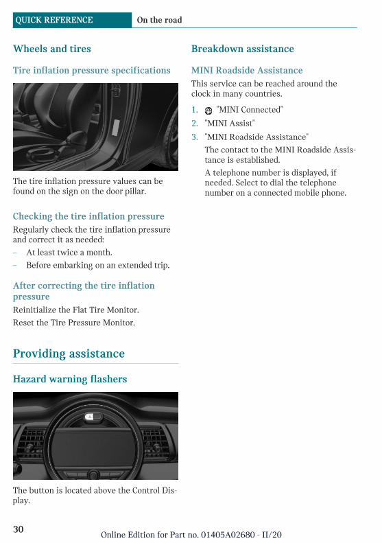
Wheels and tires
Tire inflation pressure specifications
The tire inflation pressure values can befound on the sign on the door pillar.
Checking the tire inflation pressureRegularly check the tire inflation pressureand correct it as needed:
– At least twice a month.
– Before embarking on an extended trip.
After correcting the tire inflationpressureReinitialize the Flat Tire Monitor.
Reset the Tire Pressure Monitor.
Providing assistance
Hazard warning flashers
The button is located above the Control Dis-play.
Breakdown assistance
MINI Roadside AssistanceThis service can be reached around theclock in many countries.
1. "MINI Connected"
2. "MINI Assist"
3. "MINI Roadside Assistance"
The contact to the MINI Roadside Assis-tance is established.
A telephone number is displayed, ifneeded. Select to dial the telephonenumber on a connected mobile phone.
Seite 30
QUICK REFERENCE On the road
30Online Edition for Part no. 01405A02680 - II/20

Seite 31
On the road QUICK REFERENCE
31Online Edition for Part no. 01405A02680 - II/20

Cockpit
Vehicle features and options
This chapter describes all standard, country-specific and optional features offered withthe series. It also describes features andfunctions that are not necessarily available
in your vehicle, e.g., due to the selected op-tions or country versions. This also appliesto safety-related functions and systems.When using these functions and systems,the applicable laws and regulations must beobserved.
In the vicinity of the steering wheel
1 Power windows 81
2 Exterior mirror operation 92
3 Buttons of the central locking sys-tem 71
4 Lights
Front fog lights 138
Light switch 135
Lights off
Daytime running lights 137
Parking lights 135
Low beams 135
Seite 32
AT A GLANCE Cockpit
32Online Edition for Part no. 01405A02680 - II/20

Automatic headlight con-trol 136
Cornering light 137
High-beam Assistant 137Instrument lighting 139
5 Steering wheel buttons, left
Cruise control on/off 167
Cruise control: to store thespeed
Pausing, continuing cruisecontrol
Cruise control: increase speed
Cruise control: reduce speed
6 Steering column stalk, left
Turn signal 109
High beams, head-light flasher 109
High-beam Assistant 137
Roadside parking lights 136
Onboard Computer 129
7 Instrument cluster 118
8 Steering column stalk, right
Wipers 109
Wiper on Canadian mod-els 113Rain sensor 110
Rain sensor on Canadian mod-els 114Cleaning windows 111
Rear window wiper in Cana-dian models 112
Rear window wiper 112
Clean the rear window 112
9 Steering wheel buttons, right
Voice activation 44
Telephone
Confirm the selection 128
Move selection up 128
Move selection down 128
Increase volume
Reduce volume
10 Horn, entire surface
11 Adjusting the steering wheel 94
Seite 33
Cockpit AT A GLANCE
33Online Edition for Part no. 01405A02680 - II/20
12 Unlocking the hood 244
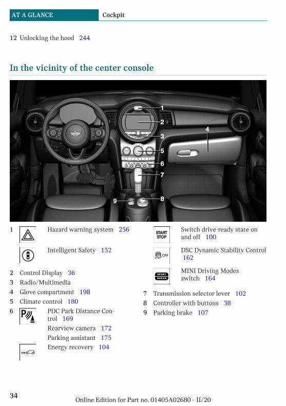
In the vicinity of the center console
1 Hazard warning system 256
Intelligent Safety 152
2 Control Display 36
3 Radio/Multimedia
4 Glove compartment 198
5 Climate control 180
6 PDC Park Distance Con-trol 169
Rearview camera 172
Parking assistant 175Energy recovery 104
Switch drive-ready state onand off 100
DSC Dynamic Stability Control 162
MINI Driving Modesswitch 164
7 Transmission selector lever 102
8 Controller with buttons 38
9 Parking brake 107
Seite 34
AT A GLANCE Cockpit
34Online Edition for Part no. 01405A02680 - II/20
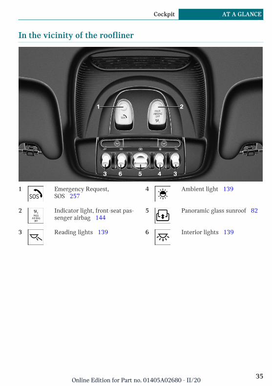
In the vicinity of the roofliner
1 Emergency Request,SOS 257
2 Indicator light, front-seat pas-senger airbag 144
3 Reading lights 139
4 Ambient light 139
5 Panoramic glass sunroof 82
6 Interior lights 139
Seite 35
Cockpit AT A GLANCE
35Online Edition for Part no. 01405A02680 - II/20
Central Information Display (CID)
Vehicle features and options
This chapter describes all standard, country-specific and optional features offered withthe series. It also describes features andfunctions that are not necessarily availablein your vehicle, e.g., due to the selected op-tions or country versions. This also appliesto safety-related functions and systems.When using these functions and systems,the applicable laws and regulations must beobserved.
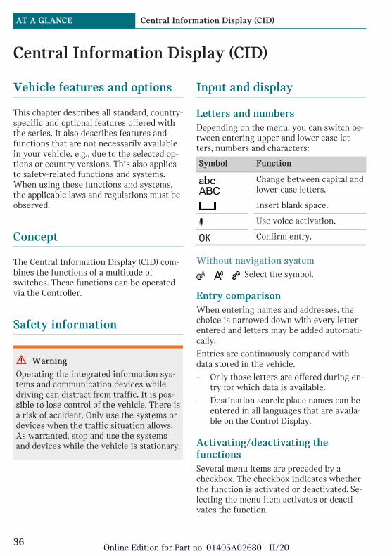
Concept
The Central Information Display (CID) com-bines the functions of a multitude ofswitches. These functions can be operatedvia the Controller.
Safety information
Warning
Operating the integrated information sys-tems and communication devices whiledriving can distract from traffic. It is pos-sible to lose control of the vehicle. There isa risk of accident. Only use the systems ordevices when the traffic situation allows.As warranted, stop and use the systemsand devices while the vehicle is stationary.
Input and display
Letters and numbersDepending on the menu, you can switch be-tween entering upper and lower case let-ters, numbers and characters:
Symbol Function
Change between capital andlower-case letters.
Insert blank space.
Use voice activation.
Confirm entry.
Without navigation system Select the symbol.
Entry comparisonWhen entering names and addresses, thechoice is narrowed down with every letterentered and letters may be added automati-cally.
Entries are continuously compared withdata stored in the vehicle.
– Only those letters are offered during en-try for which data is available.
– Destination search: place names can beentered in all languages that are availa-ble on the Control Display.
Activating/deactivating thefunctionsSeveral menu items are preceded by acheckbox. The checkbox indicates whetherthe function is activated or deactivated. Se-lecting the menu item activates or deacti-vates the function.
Seite 36
AT A GLANCE Central Information Display (CID)
36Online Edition for Part no. 01405A02680 - II/20
Function is activated.
Function is deactivated.
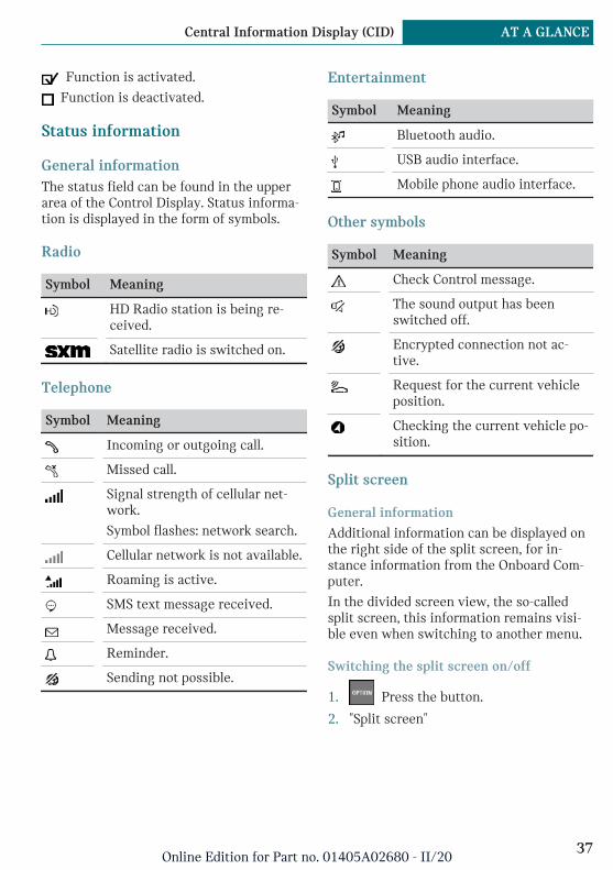
Status information
General informationThe status field can be found in the upperarea of the Control Display. Status informa-tion is displayed in the form of symbols.
Radio
Symbol Meaning
HD Radio station is being re-ceived.
Satellite radio is switched on.
Telephone
Symbol Meaning
Incoming or outgoing call.
Missed call.
Signal strength of cellular net-work.
Symbol flashes: network search.
Cellular network is not available.
Roaming is active.
SMS text message received.
Message received.
Reminder.
Sending not possible.
Entertainment
Symbol Meaning
Bluetooth audio.
USB audio interface.
Mobile phone audio interface.
Other symbols
Symbol Meaning
Check Control message.
The sound output has beenswitched off.
Encrypted connection not ac-tive.
Request for the current vehicleposition.
Checking the current vehicle po-sition.
Split screen
General information
Additional information can be displayed onthe right side of the split screen, for in-stance information from the Onboard Com-puter.
In the divided screen view, the so-calledsplit screen, this information remains visi-ble even when switching to another menu.
Switching the split screen on/off
1. Press the button.
2. "Split screen"
Seite 37
Central Information Display (CID) AT A GLANCE
37Online Edition for Part no. 01405A02680 - II/20

Selecting the display
The display can be selected in menus whichsupport the split screen function.
1. Move the Controller to the right untilthe split screen is selected.
2. Press the Controller.
3. Select the desired setting.
Specifying the number of displays
It is possible to specify the number of dis-plays.
1. Move the Controller to the right untilthe split screen is selected.
2. Press the Controller.
3. "Personalize menu"
4. Select the desired setting.
5. Move the Controller to the left.
Control elements
Overview
1 Control Display with touchscreen
2 Controller with buttons
Control Display
General informationTo clean the Control Display, follow the careinstructions, refer to page 266.
In the case of very high temperatures onthe Control Display, for instance due to in-tense solar radiation, the brightness may bereduced down to complete deactivation.Once the temperature is reduced, for in-stance through shade or air conditioning,the normal functions are restored.
Safety information
NOTICE
Objects in the area in the front of the Con-trol Display can shift and damage the Con-trol Display. There is a risk of damage toproperty. Do not place objects in the areain front of the Control Display.
Switching on/off automaticallyThe Control Display is switched on automat-ically when the vehicle is unlocked or assoon as the Control Display is needed foroperation.
In certain situations, the Control Display isswitched off automatically, for instance ifno operation is performed on the vehicle forseveral minutes.
Switching on/off manuallyThe Control Display can also be switched offmanually.
1. Press the button.
2. "Turn off control display"
Press the Controller or any button on theController to switch it back on again.
Controller with navigation system
General informationThe buttons can be used to open the menusdirectly. The Controller can be used to se-lect menu items and enter the settings.
Seite 38
AT A GLANCE Central Information Display (CID)
38Online Edition for Part no. 01405A02680 - II/20
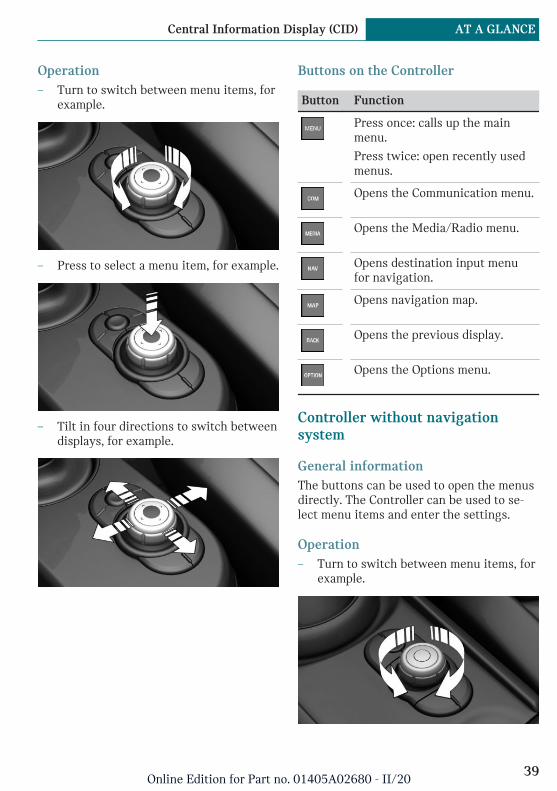
Operation– Turn to switch between menu items, for
example.
– Press to select a menu item, for example.
– Tilt in four directions to switch betweendisplays, for example.
Buttons on the Controller
Button Function
Press once: calls up the mainmenu.
Press twice: open recently usedmenus.
Opens the Communication menu.
Opens the Media/Radio menu.
Opens destination input menufor navigation.
Opens navigation map.
Opens the previous display.
Opens the Options menu.
Controller without navigationsystem
General informationThe buttons can be used to open the menusdirectly. The Controller can be used to se-lect menu items and enter the settings.
Operation– Turn to switch between menu items, for
example.
Seite 39
Central Information Display (CID) AT A GLANCE
39Online Edition for Part no. 01405A02680 - II/20
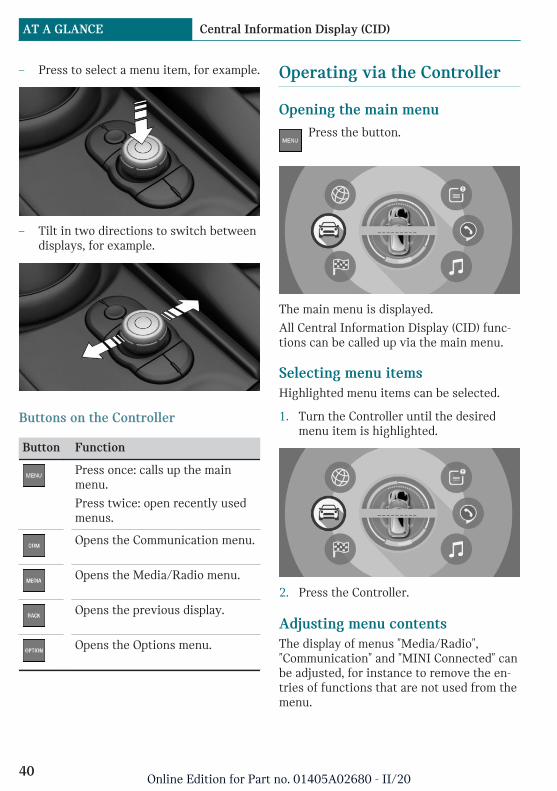
– Press to select a menu item, for example.
– Tilt in two directions to switch betweendisplays, for example.
Buttons on the Controller
Button Function
Press once: calls up the mainmenu.
Press twice: open recently usedmenus.
Opens the Communication menu.
Opens the Media/Radio menu.
Opens the previous display.
Opens the Options menu.
Operating via the Controller
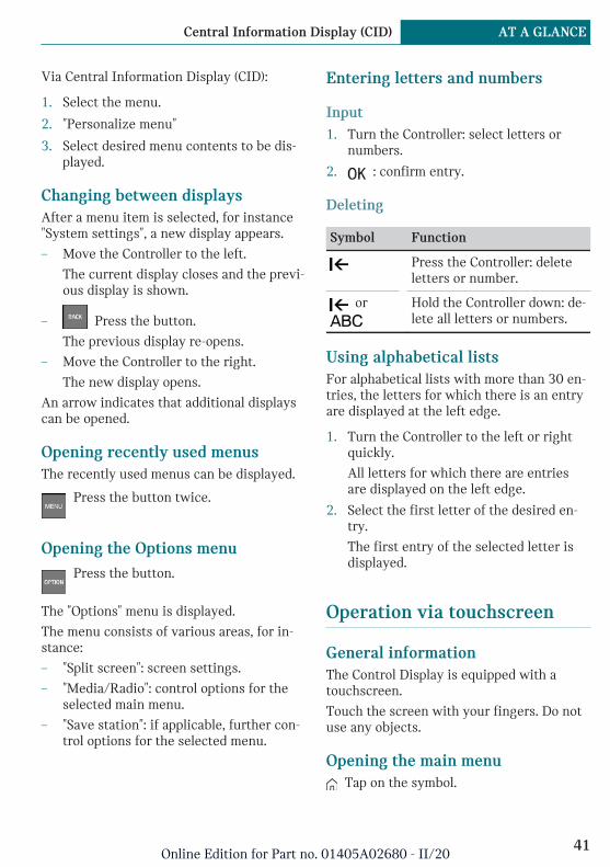
Opening the main menuPress the button.
The main menu is displayed.
All Central Information Display (CID) func-tions can be called up via the main menu.
Selecting menu itemsHighlighted menu items can be selected.
1. Turn the Controller until the desiredmenu item is highlighted.
2. Press the Controller.
Adjusting menu contentsThe display of menus "Media/Radio","Communication" and "MINI Connected" canbe adjusted, for instance to remove the en-tries of functions that are not used from themenu.
Seite 40
AT A GLANCE Central Information Display (CID)
40Online Edition for Part no. 01405A02680 - II/20
Via Central Information Display (CID):
1. Select the menu.
2. "Personalize menu"
3. Select desired menu contents to be dis-played.
Changing between displaysAfter a menu item is selected, for instance"System settings", a new display appears.
– Move the Controller to the left.
The current display closes and the previ-ous display is shown.
– Press the button.
The previous display re-opens.
– Move the Controller to the right.
The new display opens.
An arrow indicates that additional displayscan be opened.
Opening recently used menusThe recently used menus can be displayed.
Press the button twice.
Opening the Options menuPress the button.
The "Options" menu is displayed.
The menu consists of various areas, for in-stance:
– "Split screen": screen settings.
– "Media/Radio": control options for theselected main menu.
– "Save station": if applicable, further con-trol options for the selected menu.
Entering letters and numbers
Input1. Turn the Controller: select letters or
numbers.
2. : confirm entry.
Deleting
Symbol Function
Press the Controller: deleteletters or number.
or
Hold the Controller down: de-lete all letters or numbers.
Using alphabetical listsFor alphabetical lists with more than 30 en-tries, the letters for which there is an entryare displayed at the left edge.
1. Turn the Controller to the left or rightquickly.
All letters for which there are entriesare displayed on the left edge.
2. Select the first letter of the desired en-try.
The first entry of the selected letter isdisplayed.
Operation via touchscreen
General informationThe Control Display is equipped with atouchscreen.
Touch the screen with your fingers. Do notuse any objects.
Opening the main menu Tap on the symbol.
Seite 41
Central Information Display (CID) AT A GLANCE
41Online Edition for Part no. 01405A02680 - II/20
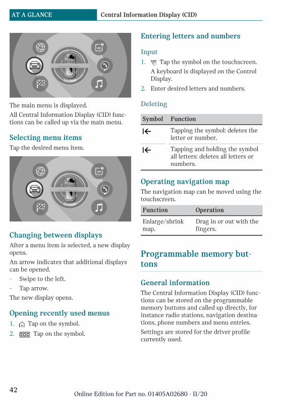
The main menu is displayed.
All Central Information Display (CID) func-tions can be called up via the main menu.
Selecting menu itemsTap the desired menu item.
Changing between displaysAfter a menu item is selected, a new displayopens.
An arrow indicates that additional displayscan be opened.
– Swipe to the left.
– Tap arrow.
The new display opens.
Opening recently used menus1. Tap on the symbol.
2. Tap on the symbol.
Entering letters and numbers
Input1. Tap the symbol on the touchscreen.
A keyboard is displayed on the ControlDisplay.
2. Enter desired letters and numbers.
Deleting
Symbol Function
Tapping the symbol: deletes theletter or number.
Tapping and holding the symbolall letters: deletes all letters ornumbers.
Operating navigation mapThe navigation map can be moved using thetouchscreen.
Function Operation
Enlarge/shrinkmap.
Drag in or out with thefingers.
Programmable memory but-tons
General informationThe Central Information Display (CID) func-tions can be stored on the programmablememory buttons and called up directly, forinstance radio stations, navigation destina-tions, phone numbers and menu entries.
Settings are stored for the driver profilecurrently used.
Seite 42
AT A GLANCE Central Information Display (CID)
42Online Edition for Part no. 01405A02680 - II/20

Storing a function1. Select the function via the Central Infor-
mation Display (CID).
2. Press and hold the desired but-ton, until a signal sounds.
Executing a functionPress the button.
The function will work immediately.This means, for instance that the number isdialed when a phone number is selected.
Displaying the key assignmentTouch buttons with finger. Do not weargloves or use objects.
The assignment of the buttons is displayedin the upper area of the Control Display.
Deleting the button assignments1. Press buttons 1 and 6 simultaneously
for approx. 5 seconds.
2. "OK"
Seite 43
Central Information Display (CID) AT A GLANCE
43Online Edition for Part no. 01405A02680 - II/20
Voice activation system
Vehicle features and options
This chapter describes all standard, country-specific and optional features offered withthe series. It also describes features andfunctions that are not necessarily availablein your vehicle, e.g., due to the selected op-tions or country versions. This also appliesto safety-related functions and systems.When using these functions and systems,the applicable laws and regulations must beobserved.
Concept
Most functions displayed on the ControlDisplay can be operated by voice commandsvia the voice activation system. The systemsupports you with announcements duringinput.
General information
– Functions that can only be used whenthe vehicle is stationary can only be op-erated via the voice activation system toa limited extent.
– The system uses a special microphoneon the driver's side.
– ›...‹ in the Owner's Manual denotes ver-bal instructions to use with the voice ac-tivation system.
Functional requirements
– A language must be set via the ControlDisplay that is supported by the voice
activation system. To set the language,refer to page 48.
– Always say commands in the languageof the voice activation system.
Using the voice activation sys-tem
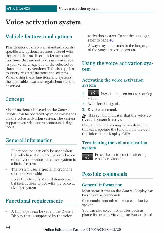
Activating the voice activationsystem
1. Press the button on the steeringwheel.
2. Wait for the signal.
3. Say the command.
This symbol indicates that the voice ac-tivation system is active.
No other commands may be available. Inthis case, operate the function via the Cen-tral Information Display (CID).
Terminating the voice activationsystem
Press the button on the steeringwheel or ›Cancel‹.
Possible commands
General informationMost menu items on the Control Display canbe spoken as commands.
Commands from other menus can also bespoken.
You can also select list entries such asphone list entries via voice activation. Read
Seite 44
AT A GLANCE Voice activation system
44Online Edition for Part no. 01405A02680 - II/20

these list entries out loud exactly as theyare shown in the respective list.
Displaying possible commandsThe following is displayed in the top area ofthe Control Display:
– Some possible commands for the currentmenu.
– Some possible commands from othermenus.
– Status of the voice recognition.
– Encrypted connection is not availa-ble.
Help on the voice activation system– ›General information on voice control‹:
have information on the operating prin-ciple of the voice activation system readout loud.
– ›Help‹: have help for the current menuread out loud.
Example: opening the tone set-tings
The commands of the menu items are spo-ken just as they are selected via the Con-troller.
1. Switch on the Entertainment sound out-put, if needed.
2. Press the button on the steeringwheel.
3. ›Media and radio‹
4. ›Tone‹
Adjusting
Setting the languageThe language to be used for voice activationand system announcements can be set.
Via the Central Information Display (CID):
1. "My MINI"
2. "System settings"
3. If necessary, "Language"
4. "Language:"
5. Select the desired language.
Setting the voice dialogYou can set the system to use standard dia-log or a short version.
The short version of the voice dialog playsback short messages in abbreviated form.
Via the Central Information Display (CID):
1. "My MINI"
2. "System settings"
3. "Language"
4. "Speech mode:"
5. Select the desired setting.
Speaking during voice outputIt is possible to answer during inquiries ofthe voice activation system. The functioncan be deactivated if inquiries are often un-desirably interrupted, for instance due tobackground noise or conversations in thevehicle.
Via the Central Information Display (CID):
1. "My MINI"
2. "System settings"
3. "Language"
4. "Speaking during voice output"
Seite 45
Voice activation system AT A GLANCE
45Online Edition for Part no. 01405A02680 - II/20
Activating voice recognition viathe serverThe voice recognition feature via the serverprovides a dictation function and a naturalmethod of entering destinations while im-proving the quality of voice recognition. Touse the functions, data is transmitted to aservice provider via an encrypted connec-tion and stored locally there.
Via the Central Information Display (CID):
1. "My MINI"
2. "System settings"
3. "Language"
4. "Server speech recognition"
Adjusting the volumeTurn the volume button during the spokeninstructions until the desired volume is set.
– The volume remains constant even if thevolume of other audio sources ischanged.
– The volume is stored for the profile cur-rently used.
Information on EmergencyRequests
Do not use the voice activation system toinitiate an Emergency Request. In stressfulsituations, the voice and vocal pitch canchange. This can unnecessarily delay the es-tablishment of a phone connection.
Instead, use the SOS button, refer topage 257, close to the interior mirror.
System limits
– Certain noises can be detected and maylead to problems. Keep the doors, win-dows, and glass sunroof closed.
– Noises from the front passenger or therear seat bench can impair the system.Avoid making other noise in the vehiclewhile speaking.
– Major language dialects can cause prob-lems with the voice recognition feature.Speak loud and clear.
Using the voice activation sys-tem of the smartphone
A smartphone connected to the vehicle canbe used via voice activation.
Activate voice command response on thesmartphone for this purpose.
1. Press and hold the button on thesteering wheel for approx. 3 seconds.
Voice command response is activated onthe smartphone.
2. Release the button.
If activation is successful, a confirma-tion appears on the Control Display.
If it was not possible to activate voice com-mand response, the list of Bluetooth devicesappears on the Control Display.
Amazon Alexa Car Integration
ConceptAlexa is a digital voice-controlled assistantby Amazon. With Amazon Alexa Car Inte-gration, Alexa can be used in the vehicle.
Seite 46
AT A GLANCE Voice activation system
46Online Edition for Part no. 01405A02680 - II/20

General informationSome of the Alexa functions are limited inthe vehicle to prevent any impairment ofsafety while driving.
Functional requirements– Connected Voice Services purchased via
MINI Connected Store.
– Same MINI Connected account used inthe vehicle and in the MINI Connectedapp.
– Vehicle added in the MINI Connectedapp.
– Amazon account and MINI account con-nected in the MINI Connected app.
– Smartphone connected to the vehicle viaBluetooth or USB.
Activation in the MINI ConnectedappThe Amazon Alexa Car Integration is acti-vated in the MINI Connected app.
Follow the instructions in the app.
Activation in the vehicleAn authorization for the use of AmazonAlexa Car Integration is required every timebefore starting a trip.
1. Authorizing Amazon Alexa Car Integra-tion:
– Connect the smartphone to the vehi-cle via Bluetooth.
– Selects appropriate driver profile, re-fer to page 75.
2. Press the button on the steeringwheel.
3. Wait for the signal.
4. Say activation word ›Alexa‹ and desiredcommand.
Information about the active function isdisplayed on the Control Display.
MalfunctionIn case of a malfunction, switch off thedrive-ready state and restart again.
Seite 47
Voice activation system AT A GLANCE
47Online Edition for Part no. 01405A02680 - II/20
General settings
Vehicle features and options
This chapter describes all standard, country-specific and optional features offered withthe series. It also describes features andfunctions that are not necessarily availablein your vehicle, e.g., due to the selected op-tions or country versions. This also appliesto safety-related functions and systems.When using these functions and systems,the applicable laws and regulations must beobserved.
Language
Setting the languageVia the Central Information Display (CID):
1. "My MINI"
2. "System settings"
3. If necessary, "Language"
4. "Language:"
5. Select the desired setting.
The setting is stored for the driver profilecurrently used.
Setting the voice dialogFor voice dialog for the voice activation sys-tem, refer to page 45.
Time
Setting the time zoneVia the Central Information Display (CID):
1. "My MINI"
2. "System settings"
3. "Date and time"
4. "Time zone:"
5. Select the desired setting.
The setting is stored for the driver profilecurrently used.
Setting the timeVia the Central Information Display (CID):
1. "My MINI"
2. "System settings"
3. "Date and time"
4. "Time:"
5. Turn the Controller until the desiredhours are displayed.
6. Press the Controller.
7. Turn the Controller until the desired mi-nutes are displayed.
8. Press the Controller.
Setting the time formatVia the Central Information Display (CID):
1. "My MINI"
2. "System settings"
3. "Date and time"
4. "Time format:"
5. Select the desired setting.
Seite 48
AT A GLANCE General settings
48Online Edition for Part no. 01405A02680 - II/20

The setting is stored for the driver profilecurrently used.
Date
Setting the dateVia the Central Information Display (CID):
1. "My MINI"
2. "System settings"
3. "Date and time"
4. "Date:"
5. Turn the Controller until the desired dayis displayed.
6. Press the Controller.
7. Make the settings for the month andyear.
Setting the date formatVia the Central Information Display (CID):
1. "My MINI"
2. "System settings"
3. "Date and time"
4. "Date format:"
5. Select the desired setting.
The setting is stored for the driver profilecurrently used.
Setting the units of measure-ment
You can set the units of measurement forsome values, for example, consumption, dis-tances and temperature.
Via the Central Information Display (CID):
1. "My MINI"
2. "System settings"
3. "Units"
4. Select the desired menu item.
5. Select the desired setting.
The setting is stored for the driver profilecurrently used.
Activating/deactivating thedisplay of the current vehicleposition
ConceptIf vehicle tracking has been activated, thecurrent vehicle position can be displayed inthe MINI Connected app.
Activating/deactivatingVia the Central Information Display (CID):
1. "My MINI"
2. "Vehicle settings"
3. "Vehicle tracking"
4. "Vehicle tracking"
5. Select the desired setting.
Activating/deactivatingpopup windows
For some functions, popup windows are dis-played automatically on the Control Display.Some of these popup windows can be acti-vated or deactivated.
Seite 49
General settings AT A GLANCE
49Online Edition for Part no. 01405A02680 - II/20
Via the Central Information Display (CID):
1. "My MINI"
2. "System settings"
3. "Pop-ups"
4. Select the desired setting.
The setting is stored for the driver profilecurrently used.
Control Display
BrightnessVia the Central Information Display (CID):
1. "My MINI"
2. "System settings"
3. "Displays"
4. "Control display"
5. "Brightness at night"
6. Turn the Controller until the desiredbrightness is set.
7. Press the Controller.
The setting is stored for the driver profilecurrently used.
Depending on the light conditions, thebrightness settings may not be clearly visi-ble.
ScreensaverIf no entries are made via the Central Infor-mation Display (CID), a screensaver can bedisplayed after an adjustable time.
Via the Central Information Display (CID):
1. "My MINI"
2. "System settings"
3. "Displays"
4. "Control display"
5. "Screensaver"
6. Select the desired setting.
The setting is stored for the driver profilecurrently used.
Messages
ConceptThe menu centrally displays all messages ar-riving in the vehicle in list form.
General informationThe following messages can be displayed:
– Traffic messages.
– Communication messages, for examplee-mails, SMS text messages or remind-ers.
– Check Control messages.
– Messages on service notifications.
– Messages from the vehicle manufac-turer.
Messages are additionally displayed in thestatus field.
Retrieving messagesVia the Central Information Display (CID):
1. "Notifications"
2. Select the desired message.
The menu in which the message is dis-played will open.
Deleting messagesAll messages, except Check Control mes-sages or messages from the vehicle manu-facturer, can be deleted from the list.
Check Control messages or messages fromthe vehicle manufacturer are displayed aslong as they are relevant.
Seite 50
AT A GLANCE General settings
50Online Edition for Part no. 01405A02680 - II/20
Via the Central Information Display (CID):
1. "Notifications"
2. Select the desired message.
3. Press the button.
4. "Delete this notification" or "Delete allnotifications"
AdjustingThe following settings can be adjusted:
– Select the applications, from which mes-sages will be permitted.
– Sort the messages according to date orpriority.
Via the Central Information Display (CID):
1. "My MINI"
2. "System settings"
3. "Notifications"
4. Select the desired setting.
Data protection
Data transfer
ConceptThe vehicle offers various functions whichrequire data to be transferred to MINI or aservice provider. The data transfer can bedeactivated for some functions.
General informationWith data transfer deactivated, the respec-tive function cannot be used.
Only make these settings while stationary.
Activating/deactivatingFollow the instructions on the Control Dis-play.
Via the Central Information Display (CID):
1. "My MINI"
2. "System settings"
3. "Data privacy"
4. Select the desired setting.
Deleting personal data in thevehicle
ConceptDepending on the usage, the vehicle storespersonal data, such as stored radio stations.This personal data can be permanently de-leted via the Central Information Display(CID).
General informationDepending on the vehicle equipment, thefollowing data is deleted:
– Driver profile settings.
– Stored radio stations.
– Stored programmable memory buttons.
– Travel and Onboard Computer informa-tion.
– Music hard disk.
– Navigation, for instance stored destina-tions.
– Phone book.
– Office data, for instance voice notes.
– Login accounts.
Altogether, the deletion of the data can takeup to 15 minutes.
Functional requirementData can only be deleted while stationary.
Deleting dataNote and follow the instructions on the Con-trol Display.
Seite 51
General settings AT A GLANCE
51Online Edition for Part no. 01405A02680 - II/20
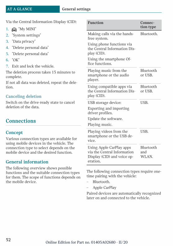
Via the Central Information Display (CID):
1. "My MINI"
2. "System settings"
3. "Data privacy"
4. "Delete personal data"
5. "Delete personal data"
6. "OK"
7. Exit and lock the vehicle.
The deletion process takes 15 minutes tocomplete.
If not all data was deleted, repeat the dele-tion.
Canceling deletionSwitch on the drive-ready state to canceldeletion of the data.
Connections
ConceptVarious connection types are available forusing mobile devices in the vehicle. Theconnection type to select depends on themobile device and the desired function.
General informationThe following overview shows possiblefunctions and the suitable connection typesfor them. The scope of functions depends onthe mobile device.
Function Connec-tion type
Making calls via the hands-free system.
Using phone functions viathe Central Information Dis-play (CID).
Using the smartphone Of-fice functions.
Bluetooth.
Playing music from thesmartphone or the audioplayer.
Bluetoothor USB.
Using compatible apps viathe Central Information Dis-play (CID).
Bluetoothor USB.
USB storage device:
Exporting and importingdriver profiles.
Update the software.
Playing music.
USB.
Playing videos from thesmartphone or the USB de-vice.
USB.
Using Apple CarPlay appsvia the Central InformationDisplay (CID) and voice op-eration.
BluetoothandWLAN.
The following connection types require one-time pairing with the vehicle:
– Bluetooth.
– Apple CarPlay
Paired devices are automatically recognizedlater on and connected to the vehicle.
Seite 52
AT A GLANCE General settings
52Online Edition for Part no. 01405A02680 - II/20
Safety information
Warning
Operating the integrated information sys-tems and communication devices whiledriving can distract from traffic. It is pos-sible to lose control of the vehicle. There isa risk of accident. Only use the systems ordevices when the traffic situation allows.As warranted, stop and use the systemsand devices while the vehicle is stationary.
Compatible devices
General informationMalfunctions may occur with devices notlisted or deviating software versions.
Displaying the vehicle identificationnumber and software part numberWhen looking for compatible devices, youmay have to state the vehicle identificationnumber and the software part number.These numbers can be displayed in the ve-hicle.
Via the Central Information Display (CID):
1. "My MINI"
2. "System settings"
3. "Mobile devices"
4. "Settings"
5. "Bluetooth® info"
6. "System information"
A software update, refer to page 58, canbe performed.
Bluetooth connection
Functional requirements– Compatible device, refer to page 53,
with Bluetooth interface.
– The vehicle key is in the vehicle.
– The device is ready for operation.
– Bluetooth is activated on the device andin the vehicle, refer to page 53.
– Bluetooth presettings, such as visibility,may be required on the device; refer tothe owner's manual of the device.
Switching on BluetoothVia the Central Information Display (CID):
1. "My MINI"
2. "System settings"
3. "Mobile devices"
4. "Settings"
5. "Bluetooth®"
Activating/deactivating telephonefunctionsTo use all supported functions of a mobilephone, the following functions must be acti-vated prior to pairing.
Via the Central Information Display (CID):
1. "My MINI"
2. "System settings"
3. "Mobile devices"
4. "Settings"
5. Select the desired setting:
– "Office"
Activate function to transmit shortmessages, e-mails, calendars, tasks,notes, and reminders to the vehicle.Costs can be incurred by transmit-ting all data to the vehicle.
– "Contact images"
Activate function to show the con-tact pictures.
6. Move the Controller to the left.
Seite 53
General settings AT A GLANCE
53Online Edition for Part no. 01405A02680 - II/20
Pairing the mobile device with thevehicleVia the Central Information Display (CID):
1. "My MINI"
2. "System settings"
3. "Mobile devices"
4. "Connect new device"
5. Select the functions for which the de-vice will be used:
– "Telephone"
– "Bluetooth® audio"
– "Apps"
– "Apple CarPlay"
The vehicle's Bluetooth name is dis-played on the Control Display.
6. On the mobile device, search for Blue-tooth devices in the vicinity.
The Bluetooth name of the vehicle ap-pears on the mobile device display.
Select the Bluetooth name of the vehi-cle.
7. Depending on the mobile device, a con-trol number is displayed or the controlnumber must be entered.
– Compare the control number dis-played on the Control Display withthe control number on the display ofthe device.
Confirm the control number on thedevice and on the Control Display.
– Enter and confirm the same controlnumber on the device and via theCentral Information Display (CID).
The device is connected and displayedin the device list.
If connection was not successful: Fre-quently Asked Questions, refer to page 54.
Frequently Asked QuestionsAll requirements are met and all requiredsteps were completed in the specified order.Despite that, the mobile device does notfunction as expected.
In this case, the following explanations canhelp:
Why could the mobile phone not be pairedor connected?
– There are too many Bluetooth devicesconnected to the mobile phone or vehi-cle.
In the vehicle, delete Bluetooth connec-tions with other devices.
Delete all known Bluetooth connectionsfrom the device list on the mobile phoneand start a new device search.
– The mobile phone is in power-save modeor has only a limited remaining batterylife.
Charge the mobile phone.
Why does the mobile phone no longer re-act?
– The applications on the mobile phone donot function anymore.
Switch the mobile phone off and onagain.
– Possibly too high or too low ambienttemperatures for mobile phone opera-tion.
Do not subject the mobile phone to ex-treme ambient temperatures.
Why can phone functions not be used viathe Central Information Display (CID)?
– The mobile phone may not be properlyconfigured, for instance as Bluetooth au-dio device.
Connect the mobile phone with the tele-phone or additional phone function.
Why are no or not all phone book entriesdisplayed or why are they incomplete?
Seite 54
AT A GLANCE General settings
54Online Edition for Part no. 01405A02680 - II/20

– Transmission of the phone book entriesis not yet complete.
– It is possible that only the phone bookentries of the mobile phone or the SIMcard are transmitted.
– It may not be possible to display phonebook entries with special characters.
– It may not be possible to transmit con-tacts from social networks.
– The number of phone book entries to bestored is too high.
– Data volume of the contact too large, forinstance due to stored information suchas notes.
Reduce the data volume of the contact.
– A mobile phone is only connected as anaudio source.
Reconfigure the mobile phone and con-nect it with the telephone or additionalphone function.
How can the phone connection quality beimproved?
– The strength of the Bluetooth signal onthe mobile phone can be adjusted, de-pending on the mobile phone.
– Insert the mobile phone into the snap-inadapter or place it in the area of the cen-ter console.
– Insert the mobile phone into the wire-less charging tray.
– Adjust the volume of the microphoneand loudspeakers separately.
If all points in this list have been checkedand the required function is still not availa-ble, contact the hotline, a dealer’s servicecenter or another qualified service center orrepair shop.
USB connection
General informationThe following mobile devices can be con-nected to the USB port:
– Mobile phones.
The snap-in adapter features a separateUSB port that is automatically connectedwhen a compatible mobile phone is in-serted.
– Audio devices with USB port, for in-stance MP3 players.
– USB storage devices.
Common file systems are supported.FAT32 and exFAT are the recommendedformats.
A connected USB storage device will besupplied with charge current via the USBport if the device supports this. Follow themaximum charge current of the USB port.
The following uses are possible on USBports with data transfer:
– Exporting and importing driver profiles,refer to page 75.
– Playing music files via USB audio.
– Playing videos via USB video.
– Loading of software updates, refer topage 58.
Follow the following when connecting:
– Do not use force when plugging the con-nector into the USB port.
– Use a flexible adapter cable.
– Protect the USB storage device againstmechanical damage.
– Due to the large number of USB storagedevices available on the market, it can-not be guaranteed that every device isoperable on the vehicle.
– Do not expose USB storage devices toextreme environmental conditions, such
Seite 55
General settings AT A GLANCE
55Online Edition for Part no. 01405A02680 - II/20

as very high temperatures; refer to theowner's manual of the device.
– Due to the many different compressiontechniques, proper playback of the me-dia stored on the USB storage devicecannot be guaranteed in all cases.
– To ensure proper transmission of thestored data, do not charge a USB storagedevice via the onboard socket, when itis connected to the USB port.
– Depending on how the USB storage de-vice is being used, settings may be re-quired on the USB storage device, referto the owner's manual of the device.
Not compatible USB media:
– USB hard drives.
– USB hubs.
– USB memory card readers with multipleslots.
– HFS-formatted USB storage devices.
– Devices such as fans or lamps.
Functional requirementCompatible device, refer to page 53, withUSB port.
Connecting the deviceConnect the USB device using a suitableadapter cable to a USB port, refer topage 194.
The USB device is connected to the vehicleand displayed in the device list.
Apple CarPlay preparation
ConceptCarPlay allows certain functions of a com-patible Apple iPhone to be used via Sirivoice operation and the Central InformationDisplay (CID).
Functional requirements– Compatible iPhone, refer to page 53.
iPhone 5 or later with iOS 7.1 or later.
– Corresponding mobile contract.
– Bluetooth, WLAN, and Siri voice opera-tion are activated on the iPhone.
– Booking the MINI Connected service:Apple CarPlay preparation.
Switching on Bluetooth and CarPlayVia the Central Information Display (CID):
1. "My MINI"
2. "System settings"
3. "Mobile devices"
4. "Settings"
5. Select the following settings:
– "Bluetooth®"
– "Apple CarPlay"
Pairing the iPhone with CarPlayPairing an iPhone with the vehicle, refer topage 54, via Bluetooth
Select CarPlay as the function:
"Apple CarPlay"
The iPhone is connected to the vehicle anddisplayed in the device list, refer topage 57.
OperationFor more information, refer to theIntegrated Owner's Manual or the Owner'sManual for Navigation, Entertainment, Com-munication.
Frequently Asked QuestionsAll requirements are met and all requiredsteps were completed in the specified order.Despite that, the mobile device does notfunction as expected.
Seite 56
AT A GLANCE General settings
56Online Edition for Part no. 01405A02680 - II/20

In this case, the following explanations canhelp:
The iPhone has already been paired withApple CarPlay. When a new connection isestablished, CarPlay can no longer be se-lected.
– Delete the iPhone concerned from thedevice list.
– On the iPhone, delete the vehicle con-cerned from the list of stored vehiclesunder Bluetooth and under WLAN.
– Pair the iPhone as a new device.
If the steps listed have been carried out andthe required function is still not available:contact the hotline, a dealer's service centeror another qualified service center or repairshop.
Managing mobile devices
General information– After one-time pairing, the devices are
automatically recognized and recon-nected when standby state is switchedon.
– The data stored on the SIM card or inthe mobile phone is transferred to thevehicle after recognition.
– For some devices, certain settings maybe necessary, for instance authorization,see owner's manual of the device.
Displaying the device listAll devices paired and/or connected withthe vehicle are displayed in the device list.
Via the Central Information Display (CID):
1. "My MINI"
2. "System settings"
3. "Mobile devices"
A symbol indicates, for which function a de-vice is used.
Symbol Function
"Telephone"
"Additional telephone"
"Bluetooth® audio"
"Apps"
"Apple CarPlay"
Configuring the deviceFunctions can be activated or deactivatedfor paired and connected devices.
Via the Central Information Display (CID):
1. "My MINI"
2. "System settings"
3. "Mobile devices"
4. Select the desired device.
5. Select the desired setting.
If a function is assigned to a device, thefunction will be deactivated where appro-priate for a device that is already connectedand the device will be disconnected.
Disconnecting the deviceThe device's connection to the vehicle isdisconnected.
The device remains paired and can be con-nected again, refer to page 57.
Via the Central Information Display (CID):
1. "My MINI"
2. "System settings"
3. "Mobile devices"
4. Select device.
5. "Disconnect device"
Connecting the deviceA disconnected device can be reconnected.
Seite 57
General settings AT A GLANCE
57Online Edition for Part no. 01405A02680 - II/20

Via the Central Information Display (CID):
1. "My MINI"
2. "System settings"
3. "Mobile devices"
4. Select device.
5. "Connect device"
The functions that were assigned to the de-vice before disconnecting are assigned tothe device when it is reconnected. The func-tions may be deactivated on a device al-ready connected.
Deleting the deviceVia the Central Information Display (CID):
1. "My MINI"
2. "System settings"
3. "Mobile devices"
4. Select device.
5. "Delete device"
The device is disconnected and removedfrom the device list.
Swapping the telephone and additionalphoneIf two mobile phones are connected to thevehicle, the functions of the phone and ad-ditional phone can be switched.
Via the Central Information Display (CID):
1. "My MINI"
2. "System settings"
3. "Mobile devices"
4. "Settings"
5. "Swap telephone/additional tel."
Software update
General informationThe vehicle supports a large number of mo-bile devices, for example mobile phones andMP3 players. Software updates are availablefor many of the supported devices. The ve-hicle is kept up-to-date via regular vehiclesoftware updates.
Contact a dealer's service center or anotherqualified service center or repair shop forinformation on available software updates.
Displaying the version of the installedsoftwareThe software version installed in the vehicleis displayed.
Via the Central Information Display (CID):
1. "My MINI"
2. "System settings"
3. "Software update"
4. "Show current version"
If an update has been carried out before, se-lect the desired version to display additionalinformation.
Updating software via USBThe software may only be updated when thevehicle is stationary.
Via the Central Information Display (CID):
1. Store the file for the software update inthe main directory of a USB storage de-vice.
2. Connecting USB storage devices to theUSB port.
3. "My MINI"
4. "System settings"
5. "Software update"
6. "Update software"
Seite 58
AT A GLANCE General settings
58Online Edition for Part no. 01405A02680 - II/20

7. "USB"
8. "Install software"
9. "OK"
10. Wait for the update to complete.
11. Confirm system restart.
Restoring the software versionYou can restore the software to the versionprior to the last update or to its factory set-tings.
The software may only be restored whenthe vehicle is stationary.
Via the Central Information Display (CID):
1. "My MINI"
2. "System settings"
3. "Software update"
4. "Restore software"
5. – "Previous version"
The previous software version is re-stored.
– "Default software settings"
The first software version is re-stored.
6. "Remove software"
7. "OK"
8. Wait for restore.
9. Confirm system restart.
Seite 59
General settings AT A GLANCE
59Online Edition for Part no. 01405A02680 - II/20

Owner's Manual media
Vehicle features and options
This chapter describes all standard, country-specific and optional features offered withthe series. It also describes features andfunctions that are not necessarily availablein your vehicle, e.g., due to the selected op-tions or country versions. This also appliesto safety-related functions and systems.When using these functions and systems,the applicable laws and regulations must beobserved.
General information
You can use the following media formats tocall up the content in the Owner's Manual:
– Printed Owner's Manual, refer topage 60.
– Integrated Owner's Manual in the vehi-cle, refer to page 60.
Printed Owner's Manual
ConceptThe printed Owner's Manual describes allstandard, country-specific, and optional fea-tures offered with the series.
General informationThe Owner's Manual for Navigation, Enter-tainment, and Communication can be ob-tained as a printed book from the servicecenter.
Supplementary Owner's ManualsAlso follow the Supplementary Owner'sManuals, which are included in addition tothe onboard literature.
Integrated Owner's Manual inthe vehicle
ConceptThe Integrated Owner's Manual specificallydescribes features and functions found inthe vehicle. The Integrated Owner's Manualcan be displayed on the Control Display.
Selecting the Owner's Manual
1. Press the button.
2. "My MINI"
3. "Owner's Manual"
4. Select the desired method of accessingthe contents.
Scrolling through the Owner'sManualTurn the Controller, until the next or previ-ous contents are displayed.
Context help
General informationThe section of the Owner's Manual relatingto the function that is currently selectedcan be displayed directly.
Seite 60
AT A GLANCE Owner's Manual media
60Online Edition for Part no. 01405A02680 - II/20

Opening via Central InformationDisplay (CID)Change directly to the Options menu fromthe function on the Control Display:
1. Press the button.
2. "Owner's Manual"
Opening when a Check Controlmessage is displayedDirectly from the Check Control message onthe Control Display:
"Owner's Manual"
Changing between a function and theOwner's ManualTo switch from a function, for instanceradio, to the Owner's Manual on the ControlDisplay and to alternate between the twodisplays:
1. Press the button.
2. "Owner's Manual"
3. Select the desired page in the Owner'sManual.
4. Press the button again to return tothe last displayed function.
5. Press the button to return to thepage of the Owner's Manual displayedlast.
To alternate continuously between the lastdisplayed function and the last displayedpage of the Owner's Manual, repeat steps 4& 5. Opens a new display every time.
Programmable memory buttons
General informationThe Owner's Manual can be stored on theprogrammable memory buttons and calledup directly.
Storing1. Select the desired entry point via the
Central Information Display (CID):
– "Quick reference"
– "Search by pictures"
– "Keyword search"
– "Animations"
2. Press and hold the desired but-ton, until a signal sounds.
Executing
Press the button.
The Owner's Manual is displayedimmediately.
Seite 61
Owner's Manual media AT A GLANCE
61Online Edition for Part no. 01405A02680 - II/20
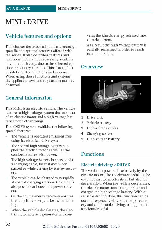
MINI eDRIVE
Vehicle features and options
This chapter describes all standard, country-specific and optional features offered withthe series. It also describes features andfunctions that are not necessarily availablein your vehicle, e.g., due to the selected op-tions or country versions. This also appliesto safety-related functions and systems.When using these functions and systems,the applicable laws and regulations must beobserved.
General information
This MINI is an electric vehicle. The vehiclefeatures a high-voltage system that consistsof an electric motor and a high-voltage bat-tery among other things.
The eDRIVE system exhibits the followingspecial features:
– The vehicle is operated emissions freeusing its electrical drive system.
– The special high-voltage battery sup-plies the electric motor as well as thecomfort features with power.
– The high-voltage battery is charged viaa charging cable, for instance whenparked or while driving by energy recov-ery.
– The vehicle can be charged very rapidlyat special charging stations. Charging isalso possible at household power sock-ets.
– On the go, the energy recovery ensuresthat only little energy is lost when brak-ing.
– When the vehicle decelerates, the elec-tric motor acts as a generator and con-
verts the kinetic energy released intoelectric current.
– As a result the high-voltage battery ispartially recharged in order to reachmaximum range.
Overview
1 Drive unit
2 Vehicle battery
3 High-voltage cables
4 Charging socket
5 High-voltage battery
Functions
Electric driving: eDRIVEThe vehicle is powered exclusively by theelectric motor. The accelerator pedal can beused not just for acceleration, but also fordeceleration. When the vehicle decelerates,the electric motor acts as a generator andcharges the high-voltage battery. With asensible driving style, this function can beused for especially efficient energy recov-ery and comfortable driving, using just theaccelerator pedal.
Seite 62
AT A GLANCE MINI eDRIVE
62Online Edition for Part no. 01405A02680 - II/20

Acoustic pedestrian protectionThe system generates a continuous drivingnoise during electric driving at low speeds.
CoastingAn especially efficient operating point is so-called coasting. In this case, the vehicle isdecelerated only by driving resistance andno energy flows between high-voltage bat-tery and electric motor. In order to coast,depress the accelerator pedal far enough sothat the pointer in the performance display,refer to page 120, is between the areas forePOWER and CHARGE.
Energy recovery: CHARGEThe high-voltage battery is charged whiledriving through energy recovery.
The electric motor acts as a generator andconverts the kinetic energy of the vehicleinto electrical energy.
Charging can take place in various situa-tions while the vehicle is in motion:
– As soon as the accelerator pedal is onlyslightly depressed.
– As soon as the accelerator pedal is notdepressed.
The pointer in the instrument cluster is lo-cated in the CHARGE area.
Sensible driving and early speed reductionare important to make full use of the energyrecovery feature.
Display
The eDRIVE displays, refer to page 120,provide information about the current stateof the drive and visualize the system's usein a diagram.
Energy-saving driving andmaximizing the range
Energy-saving driving is the basic prerequi-site for as large a range as possible. eDRIVEprovides various functions that assist withan energy-saving driving style and help tomonitor the range, and if needed, to in-crease it. The following descriptions providean overview of the available functions andthe personal measures.
Before drivingeDRIVE allows use of the air conditionereven before driving off. The stationary cli-mate control, refer to page 184, providesmore range than using full air conditioningwhile driving.
Parked vehicle ventilation during the charg-ing process can provide maximum rangewhen driving off.
Trip planning and special functionsof the navigation systemSeveral special functions of the navigationsystem support trip planning taking into ac-count the electric range:
– Range assistant, refer to IntegratedOwner's Manual, checks whether an en-tered navigation destination can bereached. If the range is not sufficient,various recommendations to help in-crease the range are displayed automati-cally, for instance, a consumption opti-mized route based on driving in GREENMode is displayed.
– Range map indicates the action rangeon the navigation map, refer toIntegrated Owner's Manual.
– Charging assistant under Points of In-terest in navigation, helps to find andpossibly include a public charging sta-
Seite 63
MINI eDRIVE AT A GLANCE
63Online Edition for Part no. 01405A02680 - II/20

tion in the desired route, refer toIntegrated Owner's Manual.
During driving– General driving tips, refer to page 212,
for increasing the range.
– Use the eDRIVE system efficiently, referto page 213, for an optimized drivingstyle.
– MINIMALISM Analyzer, refer topage 216, to analyze the driving style.
– GREEN and GREEN +, refer topage 214, driving mode for increasingthe range.
– Information about auxiliary users andthe range potential, refer to page 121.
After the trip– Charge vehicle, refer to page 218, and
plan next trip.
– Prepare for long downtimes, refer topage 266.
MINI Connected
The MINI Connected app provides mobility-based services and applications.
Safety of the high-voltage sys-tem
Follow the information on safety, refer topage 65.
Operating noises
Operating noises may occur due to the elec-trical system. For instance, they may occurin the following situations:
– When cooling the high-voltage batteryduring the charging process.
– When cooling the high-voltage batterywith the drive-ready state switched on.
– When climatizing the car's interior.
Long-term vehicle storage
Observe the information on vehicle storageand for longer idle periods, refer topage 266.
Seite 64
AT A GLANCE MINI eDRIVE
64Online Edition for Part no. 01405A02680 - II/20

Safety of the high-voltage system
Vehicle features and options
This chapter describes all standard, country-specific and optional features offered withthe series. It also describes features andfunctions that are not necessarily availablein your vehicle, e.g., due to the selected op-tions or country versions. This also appliesto safety-related functions and systems.When using these functions and systems,the applicable laws and regulations must beobserved.
Working on the vehicle
General informationThe manufacturer of your vehicle recom-mends that no changes be made to the vehi-cle, for instance the retrofitting of accesso-ries, that will have an effect on the vehicle’shybrid system.
Safety information
DANGER
Improperly performed work, in particularmaintenance and repair on the high-volt-age system, can lead to electric shock.There is a risk of injury, fire and danger tolife.
The manufacturer of your vehicle recom-mends that the work on the vehicle, in par-ticular maintenance and repair, be per-formed by a dealer’s service center oranother qualified service center or repairshop.
Contact with water
The high-voltage system is typically safeeven in the following example situations:
– Water in the floor area, for instance af-ter a rainstorm when the window waskept open.
– Vehicle is in water but only up to the al-lowed height.
– Fluid escapes in the cargo area.
Automatic deactivation
If an accident occurs, the high-voltage sys-tem is switched off automatically to preventrisk of danger to occupants and other traf-fic.
Read the information on What to do afteran accident, refer to page 261.
Seite 65
Safety of the high-voltage system AT A GLANCE
65Online Edition for Part no. 01405A02680 - II/20
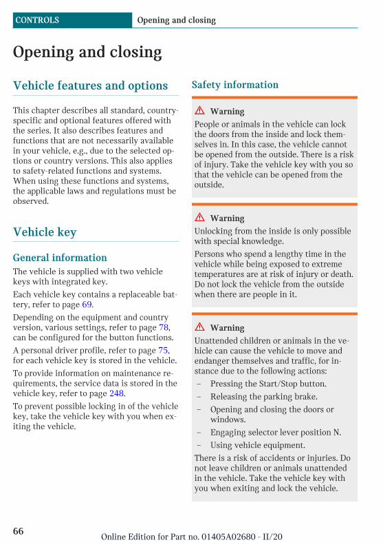
Opening and closing
Vehicle features and options
This chapter describes all standard, country-specific and optional features offered withthe series. It also describes features andfunctions that are not necessarily availablein your vehicle, e.g., due to the selected op-tions or country versions. This also appliesto safety-related functions and systems.When using these functions and systems,the applicable laws and regulations must beobserved.
Vehicle key
General informationThe vehicle is supplied with two vehiclekeys with integrated key.
Each vehicle key contains a replaceable bat-tery, refer to page 69.
Depending on the equipment and countryversion, various settings, refer to page 78,can be configured for the button functions.
A personal driver profile, refer to page 75,for each vehicle key is stored in the vehicle.
To provide information on maintenance re-quirements, the service data is stored in thevehicle key, refer to page 248.
To prevent possible locking in of the vehiclekey, take the vehicle key with you when ex-iting the vehicle.
Safety information
Warning
People or animals in the vehicle can lockthe doors from the inside and lock them-selves in. In this case, the vehicle cannotbe opened from the outside. There is a riskof injury. Take the vehicle key with you sothat the vehicle can be opened from theoutside.
Warning
Unlocking from the inside is only possiblewith special knowledge.
Persons who spend a lengthy time in thevehicle while being exposed to extremetemperatures are at risk of injury or death.Do not lock the vehicle from the outsidewhen there are people in it.
Warning
Unattended children or animals in the ve-hicle can cause the vehicle to move andendanger themselves and traffic, for in-stance due to the following actions:
– Pressing the Start/Stop button.
– Releasing the parking brake.
– Opening and closing the doors orwindows.
– Engaging selector lever position N.
– Using vehicle equipment.
There is a risk of accidents or injuries. Donot leave children or animals unattendedin the vehicle. Take the vehicle key withyou when exiting and lock the vehicle.
Seite 66
CONTROLS Opening and closing
66Online Edition for Part no. 01405A02680 - II/20
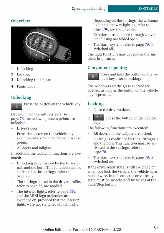
Overview
1 Unlocking
2 Locking
3 Unlocking the tailgate
4 Panic mode
UnlockingPress the button on the vehicle key.
Depending on the settings, refer topage 78, the following access points areunlocked.
– Driver's door.
Press the button on the vehicle keyagain to unlock the other vehicle accesspoints.
– All doors and tailgate.
In addition, the following functions are exe-cuted:
– Unlocking is confirmed by the turn sig-nals and the horn. This function must beactivated in the settings, refer topage 78.
– The settings stored in the driver profile,refer to page 75, are applied.
– The interior lights, refer to page 139,and the MINI logo projection areswitched on, provided that the interiorlights were not switched off manually.
– Depending on the settings, the welcomelight and pathway lighting, refer topage 136, are switched on.
– Exterior mirrors folded through conven-ient closing are folded open.
– The alarm system, refer to page 79, isswitched off.
The light functions may depend on the am-bient brightness.
Convenient openingPress and hold the button on the ve-hicle key after unlocking.
The windows and the glass sunroof areopened, as long as the button on the vehiclekey is pressed.
Locking1. Close the driver's door.
2. Press the button on the vehiclekey.
The following functions are executed:
– All doors and the tailgate are locked.
– Locking is confirmed by the turn signalsand the horn. This function must be ac-tivated in the settings, refer topage 78.
– The alarm system, refer to page 79, isswitched on.
If the drive-ready state is still switched onwhen you lock the vehicle, the vehicle hornhonks twice. In this case, the drive-readystate must be switched off by means of theStart/Stop button.
Seite 67
Opening and closing CONTROLS
67Online Edition for Part no. 01405A02680 - II/20
With Comfort Access: convenientclosing
Safety information
Warning
With convenient closing, body parts canbe jammed. There is a risk of injury. Makesure that the area of movement of thedoors is clear during convenient closing.
Closing
Press and hold the button on the ve-hicle key in the area close to the ve-hicle.
The windows and the glass sunroof areclosed, as long as the button on the vehiclekey is pressed.
The exterior mirrors are folded in.
Switch on interior lights andcourtesy light
Press the button on the vehicle keywith the vehicle locked.
The MINI logo projection is also switchedon.
These functions are not available if the inte-rior lights were switched off manually.
The light functions may depend on the am-bient brightness.
After locking, wait 10 seconds before press-ing the button again.
Tailgate
General informationTo avoid locking the vehicle key in the vehi-cle, do not place the remote control in thecargo area.
Depending on the vehicle equipment andcountry version, it is possible to specifywhether the tailgate can be unlocked withthe vehicle key and how the vehicle doorswill respond to this. To perform settings, re-fer to page 78.
Safety information
Warning
Body parts can be jammed when operatingthe tailgate. There is a risk of injury. Makesure that the area of movement of the tail-gate is clear during opening and closing.
NOTICE
The tailgate swings back and up when itopens. There is a risk of damage to prop-erty. Make sure that the area of movementof the tailgate is clear during opening andclosing.
NOTICE
Sharp-edged or pointed objects can hit thewindows and heat conductors while driv-ing. There is a risk of damage to property.Cover the edges and ensure that pointedobjects do not hit the windows.
Opening
Press and hold the button on the ve-hicle key for approx. 1 second.
The tailgate is unlocked and can be swungupward.
Panic modeYou can trigger the alarm system if you findyourself in a dangerous situation.
Seite 68
CONTROLS Opening and closing
68Online Edition for Part no. 01405A02680 - II/20

– Press the button on the vehiclekey and hold for at least 3 sec-onds.
– Briefly press the button on the vehiclekey three times in succession.
To switch off the alarm: press any button.
Replacing the battery1. Remove the integrated key from the ve-
hicle key, refer to page 71.
2. Slide the integrated key into the open-ing and raise the cover.
The battery compartment is accessible.
3. Slide the integrated key in the cover ofthe battery compartment and raise thecover.
4. Push battery in the direction of the ar-row using a pointed object and lift itout.
5. Insert a type CR 2032 battery with thepositive side facing up.
6. Insert lid and cover.
7. Push the integrated key into the vehiclekey until it engages.
Have old batteries disposed of by adealer’s service center or anotherqualified service center or repair
shop or take them to a collection point.
Additional vehicle keysAdditional vehicle keys are available from aservice center or another qualified servicecenter or repair shop.
Loss of vehicle keysA lost vehicle key can be blocked and re-placed by a dealer’s service center or an-other qualified service center or repairshop.
Malfunction
General informationA Check Control message is displayed.
Vehicle key recognition by the vehicle maymalfunction under the following circum-stances:
Seite 69
Opening and closing CONTROLS
69Online Edition for Part no. 01405A02680 - II/20
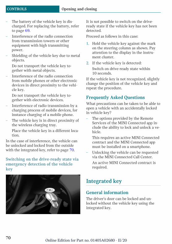
– The battery of the vehicle key is dis-charged. For replacing the battery, referto page 69.
– Interference of the radio connectionfrom transmission towers or otherequipment with high transmittingpower.
– Shielding of the vehicle key due to metalobjects.
Do not transport the vehicle key to-gether with metal objects.
– Interference of the radio connectionfrom mobile phones or other electronicdevices in direct proximity to the vehi-cle key.
Do not transport the vehicle key to-gether with electronic devices.
– Interference of radio transmission by acharging process of mobile devices, forinstance charging of a mobile phone.
– The vehicle key is in direct proximity ofthe wireless charging tray.
Place the vehicle key in a different loca-tion.
In the case of interference, the vehicle canbe unlocked and locked from the outsidewith the integrated key, refer to page 70.
Switching on the drive-ready state viaemergency detection of the vehiclekey
It is not possible to switch on the drive-ready state if the vehicle key has not beendetected.
Proceed as follows in this case:
1. Hold the vehicle key against the markon the steering column as shown. Payattention to the display in the instru-ment cluster.
2. If the vehicle key is detected:
Switch on drive-ready state within10 seconds.
If the vehicle key is not recognized, slightlychange the position of the vehicle key andrepeat the procedure.
Frequently Asked QuestionsWhat precautions can be taken to be able toopen a vehicle with an accidentally lockedin vehicle key?
– The options provided by the RemoteServices of the MINI Connected app in-clude the ability to lock and unlock a ve-hicle.
This requires an active MINI Connectedcontract and the MINI Connected appmust be installed on a smartphone.
– Unlocking the vehicle can be requestedvia the MINI Connected Call Center.
An active MINI Connected contract isrequired.
Integrated key
General informationThe driver's door can be locked and un-locked without the vehicle key using theintegrated key.
Seite 70
CONTROLS Opening and closing
70Online Edition for Part no. 01405A02680 - II/20

Safety information
Warning
Unlocking from the inside is only possiblewith special knowledge.
Persons who spend a lengthy time in thevehicle while being exposed to extremetemperatures are at risk of injury or death.Do not lock the vehicle from the outsidewhen there are people in it.
NOTICE
The door lock is permanently joined withthe door. The door handle can be moved.When pulling the door handle with theintegrated key inserted, paint or theintegrated key can be damaged. There is arisk of damage to property. Remove theintegrated key before pulling the outsidedoor handle.
Removing
Press the button, arrow 1, and pull out theintegrated key, arrow 2.
Locking/unlocking via the doorlock1. Remove lid on the door lock.
To do this, slide the integrated key intothe opening from below and remove thelid.
2. Unlock or lock the door lock using theintegrated key.
The other doors must be unlocked or lockedfrom the inside.
Alarm systemThe alarm system is not switched on if thevehicle is locked with the integrated key.
The alarm system is triggered when thedoor is opened, if the vehicle has been un-locked via the door lock.
Buttons for the central lockingsystem
General informationIn the event of a severe accident, the vehi-cle is automatically unlocked. The hazardwarning system and interior lights come on.
Seite 71
Opening and closing CONTROLS
71Online Edition for Part no. 01405A02680 - II/20
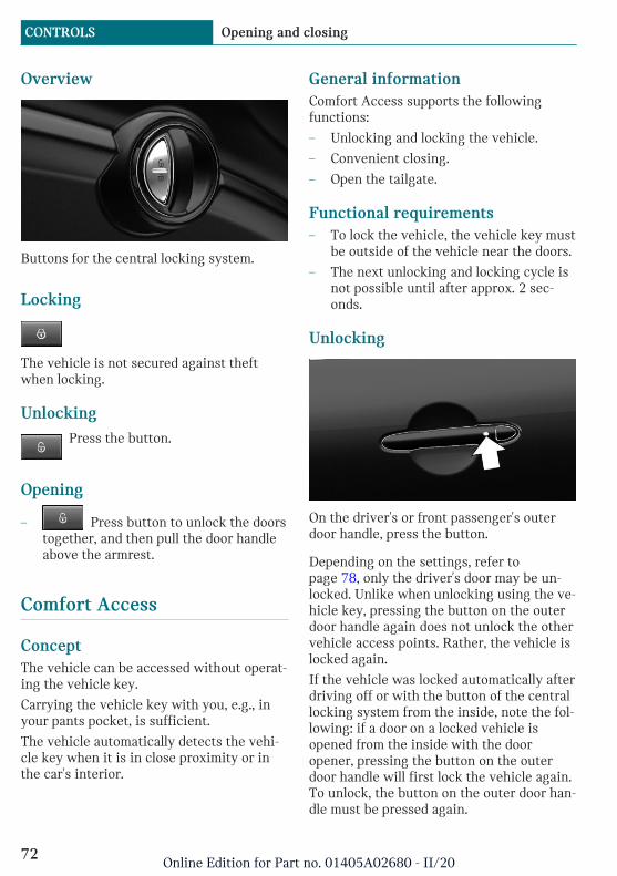
Overview
Buttons for the central locking system.
Locking
The vehicle is not secured against theftwhen locking.
UnlockingPress the button.
Opening
– Press button to unlock the doorstogether, and then pull the door handleabove the armrest.
Comfort Access
ConceptThe vehicle can be accessed without operat-ing the vehicle key.
Carrying the vehicle key with you, e.g., inyour pants pocket, is sufficient.
The vehicle automatically detects the vehi-cle key when it is in close proximity or inthe car's interior.
General informationComfort Access supports the followingfunctions:
– Unlocking and locking the vehicle.
– Convenient closing.
– Open the tailgate.
Functional requirements– To lock the vehicle, the vehicle key must
be outside of the vehicle near the doors.
– The next unlocking and locking cycle isnot possible until after approx. 2 sec-onds.
Unlocking
On the driver's or front passenger's outerdoor handle, press the button.
Depending on the settings, refer topage 78, only the driver's door may be un-locked. Unlike when unlocking using the ve-hicle key, pressing the button on the outerdoor handle again does not unlock the othervehicle access points. Rather, the vehicle islocked again.
If the vehicle was locked automatically afterdriving off or with the button of the centrallocking system from the inside, note the fol-lowing: if a door on a locked vehicle isopened from the inside with the dooropener, pressing the button on the outerdoor handle will first lock the vehicle again.To unlock, the button on the outer door han-dle must be pressed again.
Seite 72
CONTROLS Opening and closing
72Online Edition for Part no. 01405A02680 - II/20
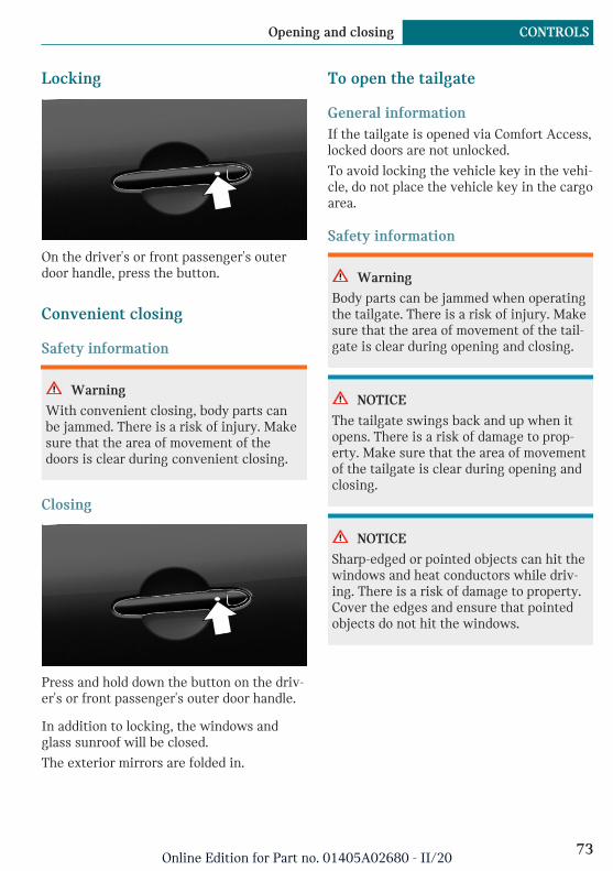
Locking
On the driver's or front passenger's outerdoor handle, press the button.
Convenient closing
Safety information
Warning
With convenient closing, body parts canbe jammed. There is a risk of injury. Makesure that the area of movement of thedoors is clear during convenient closing.
Closing
Press and hold down the button on the driv-er's or front passenger's outer door handle.
In addition to locking, the windows andglass sunroof will be closed.
The exterior mirrors are folded in.
To open the tailgate
General informationIf the tailgate is opened via Comfort Access,locked doors are not unlocked.
To avoid locking the vehicle key in the vehi-cle, do not place the vehicle key in the cargoarea.
Safety information
Warning
Body parts can be jammed when operatingthe tailgate. There is a risk of injury. Makesure that the area of movement of the tail-gate is clear during opening and closing.
NOTICE
The tailgate swings back and up when itopens. There is a risk of damage to prop-erty. Make sure that the area of movementof the tailgate is clear during opening andclosing.
NOTICE
Sharp-edged or pointed objects can hit thewindows and heat conductors while driv-ing. There is a risk of damage to property.Cover the edges and ensure that pointedobjects do not hit the windows.
Seite 73
Opening and closing CONTROLS
73Online Edition for Part no. 01405A02680 - II/20
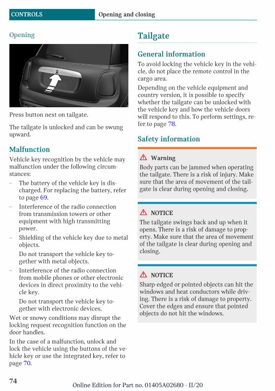
Opening
Press button next on tailgate.
The tailgate is unlocked and can be swungupward.
MalfunctionVehicle key recognition by the vehicle maymalfunction under the following circum-stances:
– The battery of the vehicle key is dis-charged. For replacing the battery, referto page 69.
– Interference of the radio connectionfrom transmission towers or otherequipment with high transmittingpower.
– Shielding of the vehicle key due to metalobjects.
Do not transport the vehicle key to-gether with metal objects.
– Interference of the radio connectionfrom mobile phones or other electronicdevices in direct proximity to the vehi-cle key.
Do not transport the vehicle key to-gether with electronic devices.
Wet or snowy conditions may disrupt thelocking request recognition function on thedoor handles.
In the case of a malfunction, unlock andlock the vehicle using the buttons of the ve-hicle key or use the integrated key, refer topage 70.
Tailgate
General informationTo avoid locking the vehicle key in the vehi-cle, do not place the remote control in thecargo area.
Depending on the vehicle equipment andcountry version, it is possible to specifywhether the tailgate can be unlocked withthe vehicle key and how the vehicle doorswill respond to this. To perform settings, re-fer to page 78.
Safety information
Warning
Body parts can be jammed when operatingthe tailgate. There is a risk of injury. Makesure that the area of movement of the tail-gate is clear during opening and closing.
NOTICE
The tailgate swings back and up when itopens. There is a risk of damage to prop-erty. Make sure that the area of movementof the tailgate is clear during opening andclosing.
NOTICE
Sharp-edged or pointed objects can hit thewindows and heat conductors while driv-ing. There is a risk of damage to property.Cover the edges and ensure that pointedobjects do not hit the windows.
Seite 74
CONTROLS Opening and closing
74Online Edition for Part no. 01405A02680 - II/20
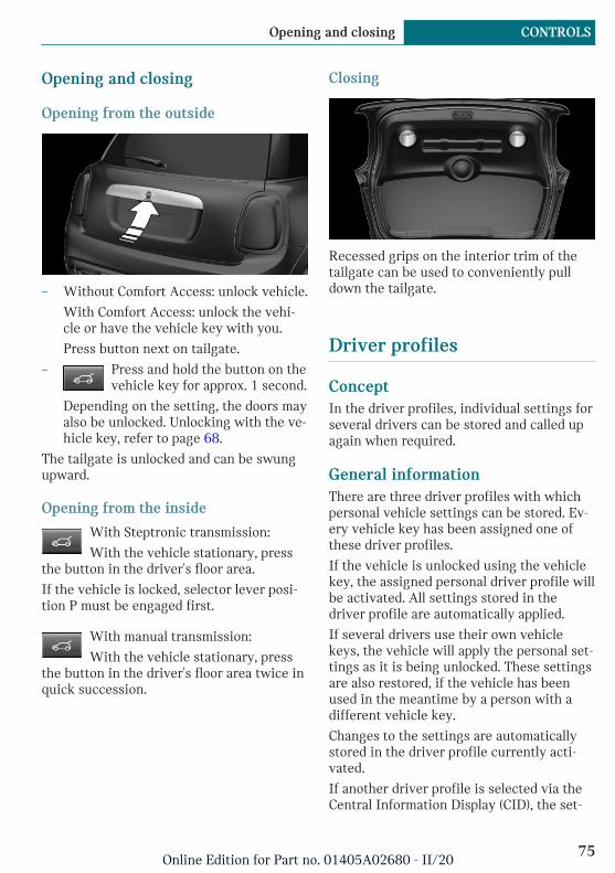
Opening and closing
Opening from the outside
– Without Comfort Access: unlock vehicle.
With Comfort Access: unlock the vehi-cle or have the vehicle key with you.
Press button next on tailgate.
– Press and hold the button on thevehicle key for approx. 1 second.
Depending on the setting, the doors mayalso be unlocked. Unlocking with the ve-hicle key, refer to page 68.
The tailgate is unlocked and can be swungupward.
Opening from the inside
With Steptronic transmission:
With the vehicle stationary, pressthe button in the driver's floor area.
If the vehicle is locked, selector lever posi-tion P must be engaged first.
With manual transmission:
With the vehicle stationary, pressthe button in the driver's floor area twice inquick succession.
Closing
Recessed grips on the interior trim of thetailgate can be used to conveniently pulldown the tailgate.
Driver profiles
ConceptIn the driver profiles, individual settings forseveral drivers can be stored and called upagain when required.
General informationThere are three driver profiles with whichpersonal vehicle settings can be stored. Ev-ery vehicle key has been assigned one ofthese driver profiles.
If the vehicle is unlocked using the vehiclekey, the assigned personal driver profile willbe activated. All settings stored in thedriver profile are automatically applied.
If several drivers use their own vehiclekeys, the vehicle will apply the personal set-tings as it is being unlocked. These settingsare also restored, if the vehicle has beenused in the meantime by a person with adifferent vehicle key.
Changes to the settings are automaticallystored in the driver profile currently acti-vated.
If another driver profile is selected via theCentral Information Display (CID), the set-
Seite 75
Opening and closing CONTROLS
75Online Edition for Part no. 01405A02680 - II/20

tings stored in it will be applied automati-cally. The new driver profile is assigned tothe vehicle key that is currently in use.
There is an additional guest profile availablethat is not assigned to any vehicle key: itcan be used to apply settings in the vehiclewithout changing the personal driver pro-files.
Functional requirementsFor the system to be able to identify thedriver profile associated to a particulardriver, the detected vehicle key must beclearly allocated to the driver.
This is the case when:
– The driver is only carrying his or herown vehicle key.
– The driver unlocks the vehicle.
– The driver gets into the vehicle throughthe driver's door.
AdjustingThe settings for the following systems andfunctions are stored in the active profile.The scope of storable settings depends oncountry and equipment.
– Unlocking and locking.
– Lights.
– Radio.
– Instrument cluster.
– Programmable memory buttons.
– Volumes, tone.
– Control Display.
– Climate control.
– Navigation.
– PDC Park Distance Control.
– Rearview camera.
– Head-up Display.
– MINI Driving Modes.
– Intelligent Safety.
Profile management
Selecting a driver profileRegardless of the vehicle key in use, a dif-ferent driver profile may be activated. Thisallows you to call up personal vehicle set-tings, even if you did not unlock the vehiclewith your own vehicle key.
Via the Central Information Display (CID):
1. "My MINI"
2. "Driver profiles"
3. Select driver profile.
4. "OK"
– All settings stored in the selected driverprofile are automatically applied.
– The called-up driver profile is assignedto the vehicle key being used at thetime.
– If the driver profile is already assignedto a different vehicle key, this driverprofile will apply to both vehicle keys.
Using a guest profileThe guest profile is for individual settingsthat are stored in none of the three personaldriver profiles.
Via the Central Information Display (CID):
1. "My MINI"
2. "Driver profiles"
3. "Drive off (guest)"
4. "OK"
The guest profile cannot be renamed. It isassigned to the vehicle key that is not usedat the time.
Renaming a driver profileA personal name can be assigned to the ac-tive driver profile to avoid confusion be-tween the driver profiles.
Seite 76
CONTROLS Opening and closing
76Online Edition for Part no. 01405A02680 - II/20
Via the Central Information Display (CID):
1. "My MINI"
2. "Driver profiles"
3. Select driver profile.
The driver profile marked with thissymbol can be renamed.
4. "Change driver profile name"
5. Enter profile name.
6. Select the symbol.
Resetting a driver profileThe settings of the driver profile currentlyin use are reset to their factory settings.
Via the Central Information Display (CID):
1. "My MINI"
2. "Driver profiles"
3. Select driver profile.
The driver profile marked with thissymbol can be reset.
4. "Reset driver profile"
5. "OK"
Exporting driver profilesMost settings of the active driver profilecan be exported.
Exporting is helpful when storing and re-trieving personal settings, for instance be-fore delivering the vehicle to a workshop.The stored driver profiles can be taken intoanother vehicle.
Via the Central Information Display (CID):
1. "My MINI"
2. "Driver profiles"
3. Select driver profile.
The driver profile marked with thissymbol can be exported.
4. "Export driver profile (USB)"
Select USB storage device as needed.
Importing driver profilesProfiles stored on a USB storage device canbe imported via the USB port.
The existing settings of the active driverprofile are overwritten with the settings ofthe imported driver profile.
Via the Central Information Display (CID):
1. "My MINI"
2. "Driver profiles"
3. Select the driver profile to overwrite.
The driver profile marked with thissymbol can be overwritten.
4. "Import driver profile (USB)"
Select USB storage device as needed.
5. Select the driver profile to be imported.
Displaying driver profiles during startThe driver profiles can be displayed at eachstartup to select the desired profile.
Via the Central Information Display (CID):
1. "My MINI"
2. "Driver profiles"
3. "Show driver profiles at startup"
System limitsA clear assignment between the vehicle keyand driver may not be possible in the fol-lowing cases, for example.
– The passenger unlocks the vehicle withhis or her own vehicle key, but anotherperson is driving.
– The driver unlocks the vehicle via Com-fort Access and has multiple vehiclekeys with him or her.
– The driver changes, but the vehicle isnot locked and unlocked.
Seite 77
Opening and closing CONTROLS
77Online Edition for Part no. 01405A02680 - II/20
– Multiple vehicle keys are located out-side of the vehicle.
Adjusting
General informationDepending on the package and country ver-sion, various settings are available for thevehicle key functions.
These settings are stored for the driver pro-file, refer to page 75, currently used.
Unlocking
DoorsVia the Central Information Display (CID):
1. "My MINI"
2. "Vehicle settings"
3. "Doors/Key"
4. "Driver's door" or "All doors"
5. Select the desired setting:
– "Driver's door only"
Only the driver's door is unlocked.Pressing again unlocks the entire ve-hicle.
– "All doors"
The entire vehicle is unlocked.
TailgateVia the Central Information Display (CID):
1. "My MINI"
2. "Vehicle settings"
3. "Doors/Key"
4.
The text next to the symbol indicatesthe current setting.
5. Select the desired setting:
– "Tailgate"
Only the tailgate is unlocked.
– "Tailgate and door(s)"
The tailgate and the doors are un-locked.
– "Tailgate opens after unlocking"
The vehicle must be unlocked beforethe tailgate can be used with the ve-hicle key.
– "Button lock"
It is not possible to use the tailgatevia the vehicle key.
Depending on the vehicle equipment andcountry version, this setting may not be of-fered.
Automatic lockingVia the Central Information Display (CID):
1. "My MINI"
2. "Vehicle settings"
3. "Doors/Key"
4. Select the desired setting:
– "Lock automatically"
The vehicle locks automatically aftera while if no door is opened after un-locking.
– "Lock after starting to drive"
The vehicle locks automatically afteryou drive off.
Automatic unlockingVia the Central Information Display (CID):
1. "My MINI"
2. "Vehicle settings"
3. "Doors/Key"
4. "Unlock at end of trip"
Seite 78
CONTROLS Opening and closing
78Online Edition for Part no. 01405A02680 - II/20

After drive-ready state is switched offby pressing the Start/Stop button, thelocked vehicle is automatically un-locked.
Confirmation signals from thevehicleVia the Central Information Display (CID):
1. "My MINI"
2. "Vehicle settings"
3. "Doors/Key"
4. Deactivate or activate the desired con-firmation signals.
– "Flash for lock/unlock"
Unlocking is signaled by two flashes,locking by one.
– With alarm system:
"Acoustic signal for lock/unlock"
Unlocking is signaled by one honk ofthe horn.
Alarm system
General informationWhen the vehicle is locked, the vehiclealarm system reacts to the followingchanges:
– Unauthorized opening of a door, thehood or the tailgate.
– Movements in the car's interior.
– Changes in the vehicle tilt, for instance,during attempts at stealing a wheel orwhen towing the vehicle.
– Disconnected battery voltage.
– Improper use of the socket for OnboardDiagnosis.
– Locking the vehicle while a device isconnected to the socket for the OBD On-
board-Diagnosis. For socket for the OBDOnboard Diagnosis, refer to page 249.
The alarm system signals these changes vis-ually and acoustically:
– Acoustic alarm:
Depending on local regulations, theacoustic alarm may be suppressed.
– Visual alarm:
By flashing of the hazard warning sys-tem and headlights, where required.
Do not modify the system to ensure func-tion of the alarm system.
Overview
Indicator light on the interior mirror.
Switching on/offThe alarm system is switched on or off assoon as the vehicle is locked with the vehi-cle key or unlocked or locked via ComfortAccess.
Opening the doors with the alarmsystem switched onThe alarm system is triggered when a dooris opened if the door was unlocked usingthe integrated key in the door lock.
Switching off the alarm, refer to page 80.
Seite 79
Opening and closing CONTROLS
79Online Edition for Part no. 01405A02680 - II/20
Opening the tailgate with the alarmsystem switched onThe tailgate can be opened even when thealarm system is switched on.
After the tailgate is closed, it is locked andmonitored again provided the doors arelocked. The hazard warning system flashesonce.
Panic modeYou can trigger the alarm system if you findyourself in a dangerous situation.
– Press the button on the vehiclekey and hold for at least 3 sec-onds.
– Briefly press the button on the vehiclekey three times in succession.
To switch off the alarm: press any button.
Signals of the indicator light– The indicator light flashes briefly every
2 seconds:
The alarm system is switched on.
– Indicator light flashes for approx.10 seconds, then it flashes briefly every2 seconds:
Interior motion sensor and tilt alarmsensor are not active, as doors, hood, ortailgate are not correctly closed. Cor-rectly closed access points are secured.
When the still open access points areclosed, the interior motion sensor andtilt alarm sensor will be switched on.
– The indicator light goes out after un-locking:
The vehicle has not been tampered with.
– The indicator light flashes after unlock-ing until standby state is switched on,but no longer than approx. 5 minutes:
An alarm has been triggered.
Tilt alarm sensorThe tilt of the vehicle is monitored.
The alarm system responds in situationssuch as attempts to steal a wheel or whenthe vehicle is towed.
Interior motion sensorThe windows and the glass sunroof must beclosed for the system to function properly.
Avoiding unintentional alarms
General informationThe tilt alarm sensor and interior motionsensor can trigger an alarm, although no un-authorized action occurred.
Possible situations for an unwanted alarm:
– In automatic vehicle washes.
– In duplex garages.
– During transport on trains carrying ve-hicles, at sea or on a trailer.
– With animals in the vehicle.
The tilt alarm sensor and the interior mo-tion sensor can be switched off in such sit-uations.
Switching off the tilt alarm sensor andinterior motion sensor
Press the button on the vehicle keywithin 10 seconds as soon as thevehicle is locked.
The indicator light lights up for approx.2 seconds and then continues to flash.
The tilt alarm sensor and interior motionsensor are switched off until the vehicle islocked again.
Switching off the alarm– Unlock the vehicle with the vehicle key.
Seite 80
CONTROLS Opening and closing
80Online Edition for Part no. 01405A02680 - II/20

– Unlock the vehicle with the integratedkey and activate the standby state viaemergency detection of the vehicle key,refer to page 69.
– With Comfort Access: if you have thevehicle key with you, unlock the vehicleusing the button on the driver's side orpassenger side door.
Power windows
General informationIf an accident of a certain severity occurs,the windows are automatically closed ex-cept a gap.
Safety information
Warning
When operating the windows, body partsand objects can be jammed. There is a riskof injury or risk of damage to property.Make sure that the area of movement ofthe windows is clear during opening andclosing.
Overview
Power windows
Opening
– Press the switch to the resistancepoint.
The window opens while the switch isbeing held.
– Press the switch beyond the resist-ance point.
The window opens automatically. Press-ing the switch again stops the motion.
Convenient opening with the vehicle key,refer to page 67.
Closing
– Pull the switch to the resistancepoint.
The window closes while the switch isbeing held.
– Pull the switch beyond the resist-ance point.
The window closes automatically if thedoor is closed. Pulling the switch againstops the motion.
Convenient closing with the vehicle key, re-fer to page 68.
Closing via Comfort Access, refer topage 73.
Jam protection system
ConceptThe jam protection prevents objects or bodyparts becoming jammed between the doorframe and window while a window is beingclosed.
General informationIf resistance or a blockage is detected whilea window is being closed, the closing actionis interrupted.
Seite 81
Opening and closing CONTROLS
81Online Edition for Part no. 01405A02680 - II/20
The window opens slightly.
Safety information
Warning
Accessories on the windows such as an-tennas can impact jam protection. There isa risk of injury. Do not install accessoriesin the area of movement of the windows.
Closing without the jam protectionsystemIn case of danger from the outside or if icemight prevent normal closing, proceed asfollows:
1. Pull the switch past the resistancepoint and hold it there.
The window closes with limited jam pro-tection. If the closing force exceeds aspecific threshold, closing is inter-rupted.
2. Pull the switch past the resistancepoint again within approx. 4 secondsand hold it there.
The window closes without jam protec-tion.
Malfunction
General informationIn certain situations a window can only beoperated to a limited extent.
– After a power failure during the openingor closing process, the a window canonly be operated to a limited extent. Thesystem must be initialized in this case.
– The power window motors are equippedwith overheating protection. If a win-dow is opened and closed several timeswithin a short period of time, the over-
heating protection switches the motoroff temporarily. Depending on the de-gree of overheating, it may only be pos-sible to close the window or it may notbe possible to operate it at all.
In this case: allow the power windowmotor to cool down.
Initializing the systemThe system can be initialized when the ve-hicle is stationary and the drive-ready stateis switched on.
During initialization, the affected windowcloses without jam protection.
Warning
When operating the windows, body partsand objects can be jammed. There is a riskof injury or risk of damage to property.Make sure that the area of movement ofthe windows is clear during opening andclosing.
1. Open the affected window completely.
2. Pull the switch to the resistancepoint and hold.
The window closes.
3. Continue holding the switch pulledto the resistance point.
The window opens and closes once ortwice after approx. 15 seconds, depend-ing on the vehicle's equipment.
4. Release switch.
Panoramic glass sunroof
General informationIn the event of a severe accident, the glasssunroof is automatically closed.
Seite 82
CONTROLS Opening and closing
82Online Edition for Part no. 01405A02680 - II/20
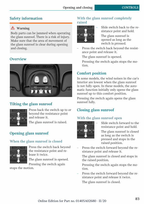
Safety information
Warning
Body parts can be jammed when operatingthe glass sunroof. There is a risk of injury.Make sure that the area of movement ofthe glass sunroof is clear during openingand closing.
Overview
Tilting the glass sunroofPress back the switch up to orbeyond the resistance pointand release it.
The glass sunroof is raised.
Opening glass sunroof
When the glass sunroof is closed
Press the switch back beyondthe resistance point and re-lease it twice.
The glass sunroof is opened.
Pressing the switch againstops the motion.
With the glass sunroof completelyraised
– Slide switch back to the re-sistance point and hold.
The glass sunroof isopened as long as theswitch is pressed.
– Press the switch back beyond the resist-ance point and release it.
The glass sunroof is opened.
Pressing the switch again stops the mo-tion.
Comfort positionIn some models, the wind noises in the car'sinterior are lowest when the glass sunroofis not fully open. In these models, the auto-matic function initially only opens the glasssunroof up to this comfort position.
Pressing the switch again opens the glasssunroof fully.
Closing glass sunroof
With the glass sunroof open– Slide switch forward to the
resistance point and hold.
The glass sunroof is closedas long as the switch ispressed and stops in theraised position.
– Press the switch forward beyond the re-sistance point and release it.
The glass sunroof is closed and stops inthe raised position.
Pressing the switch again stops the mo-tion.
– Press the switch forward beyond the re-sistance point and release it twice.
The glass sunroof is closed.
Seite 83
Opening and closing CONTROLS
83Online Edition for Part no. 01405A02680 - II/20
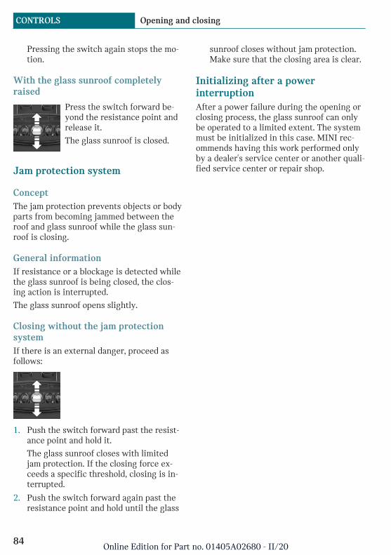
Pressing the switch again stops the mo-tion.
With the glass sunroof completelyraised
Press the switch forward be-yond the resistance point andrelease it.
The glass sunroof is closed.
Jam protection system
ConceptThe jam protection prevents objects or bodyparts from becoming jammed between theroof and glass sunroof while the glass sun-roof is closing.
General informationIf resistance or a blockage is detected whilethe glass sunroof is being closed, the clos-ing action is interrupted.
The glass sunroof opens slightly.
Closing without the jam protectionsystemIf there is an external danger, proceed asfollows:
1. Push the switch forward past the resist-ance point and hold it.
The glass sunroof closes with limitedjam protection. If the closing force ex-ceeds a specific threshold, closing is in-terrupted.
2. Push the switch forward again past theresistance point and hold until the glass
sunroof closes without jam protection.Make sure that the closing area is clear.
Initializing after a powerinterruptionAfter a power failure during the opening orclosing process, the glass sunroof can onlybe operated to a limited extent. The systemmust be initialized in this case. MINI rec-ommends having this work performed onlyby a dealer's service center or another quali-fied service center or repair shop.
Seite 84
CONTROLS Opening and closing
84Online Edition for Part no. 01405A02680 - II/20
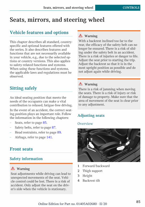
Seats, mirrors, and steering wheel
Vehicle features and options
This chapter describes all standard, country-specific and optional features offered withthe series. It also describes features andfunctions that are not necessarily availablein your vehicle, e.g., due to the selected op-tions or country versions. This also appliesto safety-related functions and systems.When using these functions and systems,the applicable laws and regulations must beobserved.
Sitting safely
An ideal seating position that meets theneeds of the occupants can make a vitalcontribution to relaxed, fatigue-free driving.
In the event of an accident, the correct seat-ing position plays an important role. Followthe information in the following chapters:
– Seats, refer to page 85.
– Safety belts, refer to page 87.
– Head restraints, refer to page 89.
– Airbags, refer to page 141.
Front seats
Safety information
Warning
Seat adjustments while driving can lead tounexpected movements of the seat. Vehi-cle control could be lost. There is a risk ofaccident. Only adjust the seat on the driv-er's side when the vehicle is stationary.
Warning
With a backrest inclined too far to therear, the efficacy of the safety belt can nolonger be ensured. There is a risk of slid-ing under the safety belt in an accident.There is a risk of injuries or danger to life.Adjust the seat prior to starting the trip.Adjust the backrest so that it is in themost upright position as possible and donot adjust again while driving.
Warning
There is a risk of jamming when movingthe seats. There is a risk of injury or riskof damage to property. Make sure that thearea of movement of the seat is clear priorto any adjustment.
Adjusting seats
Overview
1 Forward/backward
2 Thigh support
3 Height
4 Backrest tilt
Seite 85
Seats, mirrors, and steering wheel CONTROLS
85Online Edition for Part no. 01405A02680 - II/20

Forward/backward
Pull the lever and slide the seat in the de-sired direction.
After releasing the lever, move the seat for-ward or back slightly making sure it en-gages properly.
Height
Pull the lever up or press it down as often asneeded to reach the desired height.
Backrest tilt
Pull the lever, and apply your weight to thebackrest or lift it off, as necessary.
Lumbar supportThe curvature of the seat backrest can beadjusted in a way that it supports the lum-bar region of the spine. The lower back andthe spine are supported for upright posture.
Turn the wheel in order to increase or de-crease the curvature.
Thigh support
Pull the lever at the front of the seat and ad-just the thigh support.
Entering the rear
Safety information
Warning
There is a risk of jamming when movingthe seats. There is a risk of injury or riskof damage to property. Make sure that thearea of movement of the seat is clear priorto any adjustment.
Seite 86
CONTROLS Seats, mirrors, and steering wheel
86Online Edition for Part no. 01405A02680 - II/20
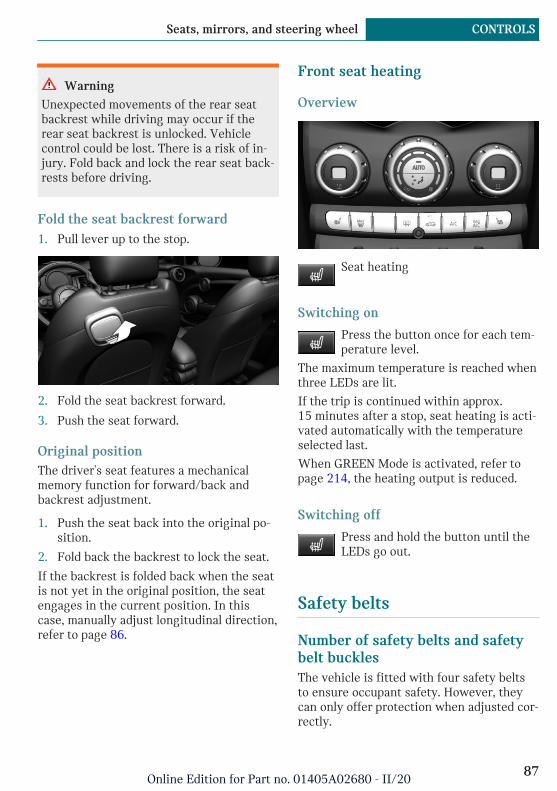
Warning
Unexpected movements of the rear seatbackrest while driving may occur if therear seat backrest is unlocked. Vehiclecontrol could be lost. There is a risk of in-jury. Fold back and lock the rear seat back-rests before driving.
Fold the seat backrest forward1. Pull lever up to the stop.
2. Fold the seat backrest forward.
3. Push the seat forward.
Original positionThe driver's seat features a mechanicalmemory function for forward/back andbackrest adjustment.
1. Push the seat back into the original po-sition.
2. Fold back the backrest to lock the seat.
If the backrest is folded back when the seatis not yet in the original position, the seatengages in the current position. In thiscase, manually adjust longitudinal direction,refer to page 86.
Front seat heating
Overview
Seat heating
Switching on
Press the button once for each tem-perature level.
The maximum temperature is reached whenthree LEDs are lit.
If the trip is continued within approx.15 minutes after a stop, seat heating is acti-vated automatically with the temperatureselected last.
When GREEN Mode is activated, refer topage 214, the heating output is reduced.
Switching off
Press and hold the button until theLEDs go out.
Safety belts
Number of safety belts and safetybelt bucklesThe vehicle is fitted with four safety beltsto ensure occupant safety. However, theycan only offer protection when adjusted cor-rectly.
Seite 87
Seats, mirrors, and steering wheel CONTROLS
87Online Edition for Part no. 01405A02680 - II/20
General informationAlways make sure that safety belts are be-ing worn by all occupants before driving off.Although airbags enhance safety by provid-ing added protection, they are not a substi-tute for safety belts.
If needed, disengage the safety belt in therear from the belt buckle on the side.
The upper shoulder strap's anchorage pointwill be correct for adult seat occupants ofevery build if the seat is correctly adjusted.
Safety information
Warning
Use of a safety belt to buckle more thanone person will potentially defeat the abil-ity of the safety belt to serve its protectivefunction. There is a risk of injuries or dan-ger to life. Do not allow more than one per-son to wear a single safety belt. Infantsand children are not allowed on an occu-pant's lap, but must be transported and se-cured in designated child restraint sys-tems.
Warning
The efficacy of safety gear, includingsafety belts, can be limited or lost whensafety belts are fastened incorrectly. Anincorrectly fastened safety belt can causeadditional injuries, for instance in theevent of an accident, braking or evasivemaneuvers. There is a risk of injuries ordanger to life. Make sure that all occu-pants are wearing safety belts correctly.
Warning
The efficacy of safety gear, includingsafety belts, may not be fully functional orfail in the following situations:
– The safety belts or safety belt bucklesare damaged, soiled, or changed inany other way.
– Belt tensioners or belt retractorswere modified.
Safety belts can be imperceptibly damagedin the event of an accident. There is a riskof injuries or danger to life. Do not modifysafety belts, safety belt buckles, belt ten-sioners, belt retractors or belt anchors andkeep them clean. Have the safety beltschecked after an accident at the dealer’sservice center or another qualified servicecenter or repair shop.
Correct use of safety belts– Wear the safety belt twist-free and tight
to your body over your lap and should-ers.
– Wear the safety belt deep on your hipsover your lap. The safety belt may notpress on your stomach.
– Do not rub the safety belt against sharpedges, or guide it or jam it in acrosshard or fragile objects.
– Avoid thick clothing.
– Re-tighten the safety belt frequently up-ward around your upper body.
Buckling the safety belt1. Guide the safety belt slowly over
shoulder and hip to put it on.
Seite 88
CONTROLS Seats, mirrors, and steering wheel
88Online Edition for Part no. 01405A02680 - II/20

2. Insert the tongue plate into the safetybelt buckle. The safety belt buckle mustengage audibly.
Unbuckling the safety belt1. Hold the safety belt firmly.
2. Press the red button in the belt buckle.
3. Guide the safety belt back into its roll-up mechanism.
Safety belt reminder for driver'sseat and front passenger seat
Display in the instrument cluster
The indicator light lights up and asignal sounds. Make sure that thesafety belts are positioned correctly.
The safety belt reminder can also be acti-vated if objects are placed on the front pas-senger seat.
Safety belt reminder for rear seats
General informationThe safety belt reminder is automaticallyactivated each time the drive-ready state isswitched on.
The safety belt reminder is also activatedwhen a passenger unbuckles a rear seatsafety belt during the trip.
Display in the instrument clusterThe indicator light in the instrument clusterilluminates after switching on the drive-ready state.
Symbol Description
Green: the safety belt is buckledon the corresponding rear seat.
Red: the safety belt is not buck-led on the corresponding rearseat.
Front head restraints
Safety information
Warning
A missing protective effect due to re-moved or not correctly adjusted head re-straints can cause injuries in the head andneck area. There is a risk of injury.
– Before driving, install the removedhead restraints on the occupied seats.
– Adjust the head restraint so its centersupports the back of the head at asclose to eye level as possible.
– Adjust the distance so that the headrestraint is as close as possible to theback of the head. Adjust the distancevia the backrest tilt as needed.
Warning
Body parts can be jammed when movingthe head restraint. There is a risk of injury.Make sure that the area of movement isclear when moving the head restraint.
Seite 89
Seats, mirrors, and steering wheel CONTROLS
89Online Edition for Part no. 01405A02680 - II/20

Warning
Objects on the head restraint reduce theprotective effect in the head and neckarea. There is a risk of injury.
– Do not use seat or head restraint cov-ers.
– Do not hang objects, for instanceclothes hangers, directly on the headrestraint.
– Only use accessories that have beendetermined to be safe for attachmentto a head restraint.
– Do not use any accessories, for in-stance pillows, while driving.
Adjusting the height
– To lower: press the button, arrow 1, andpush the head restraint down.
– To raise: push the head restraint up.
After setting the height, make sure that thehead restraint engages correctly.
RemovingOnly remove the head restraint if no onewill be sitting in the seat in question.
1. If necessary, fold the rear seat backrestforward.
2. Pull head restraint up as far as possible.
3. Press the button, arrow 1, and pull thehead restraint out completely.
InstallingProceed in the reverse order to install thehead restraint.
Rear head restraints
Safety information
Warning
A missing protective effect due to re-moved or not correctly adjusted head re-straints can cause injuries in the head andneck area. There is a risk of injury.
– Before driving, install the removedhead restraints on the occupied seats.
– Adjust the head restraint so its centersupports the back of the head at asclose to eye level as possible.
– Adjust the distance so that the headrestraint is as close as possible to theback of the head. Adjust the distancevia the backrest tilt as needed.
Seite 90
CONTROLS Seats, mirrors, and steering wheel
90Online Edition for Part no. 01405A02680 - II/20

Warning
Body parts can be jammed when movingthe head restraint. There is a risk of injury.Make sure that the area of movement isclear when moving the head restraint.
Warning
Objects on the head restraint reduce theprotective effect in the head and neckarea. There is a risk of injury.
– Do not use seat or head restraint cov-ers.
– Do not hang objects, for instanceclothes hangers, directly on the headrestraint.
– Only use accessories that have beendetermined to be safe for attachmentto a head restraint.
– Do not use any accessories, for in-stance pillows, while driving.
Adjusting the height
– To lower: press the button, arrow 1, andpush the head restraint down.
– To raise: push the head restraint up.
After setting the height, make sure that thehead restraint engages correctly.
Fold down
– To fold down: press the button, arrow 1,and press down the head restraint, ar-row 2.
– Forward: fold the head restraint towardthe front as far as it will go. Make surethat the head restraint engages cor-rectly.
RemovingOnly remove the head restraint if no onewill be sitting in the seat in question.
1. Fold down the rear seat backrest, referto page 203, in question.
2. Pull head restraint up against the resist-ance.
3. Press the button, arrow 1, and pull thehead restraint out completely.
InstallingProceed in the reverse order to install thehead restraint.
Seite 91
Seats, mirrors, and steering wheel CONTROLS
91Online Edition for Part no. 01405A02680 - II/20
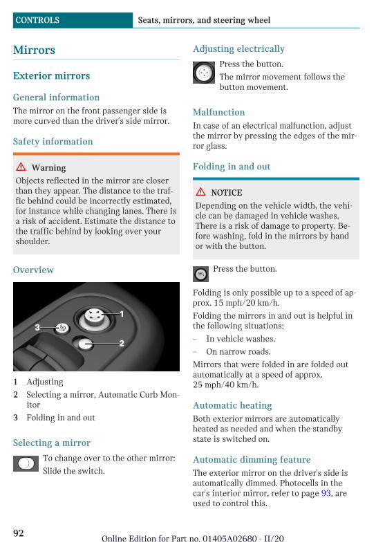
Mirrors
Exterior mirrors
General informationThe mirror on the front passenger side ismore curved than the driver's side mirror.
Safety information
Warning
Objects reflected in the mirror are closerthan they appear. The distance to the traf-fic behind could be incorrectly estimated,for instance while changing lanes. There isa risk of accident. Estimate the distance tothe traffic behind by looking over yourshoulder.
Overview
1 Adjusting
2 Selecting a mirror, Automatic Curb Mon-itor
3 Folding in and out
Selecting a mirror
To change over to the other mirror:
Slide the switch.
Adjusting electrically
Press the button.
The mirror movement follows thebutton movement.
MalfunctionIn case of an electrical malfunction, adjustthe mirror by pressing the edges of the mir-ror glass.
Folding in and out
NOTICE
Depending on the vehicle width, the vehi-cle can be damaged in vehicle washes.There is a risk of damage to property. Be-fore washing, fold in the mirrors by handor with the button.
Press the button.
Folding is only possible up to a speed of ap-prox. 15 mph/20 km/h.
Folding the mirrors in and out is helpful inthe following situations:
– In vehicle washes.
– On narrow roads.
Mirrors that were folded in are folded outautomatically at a speed of approx.25 mph/40 km/h.
Automatic heatingBoth exterior mirrors are automaticallyheated as needed and when the standbystate is switched on.
Automatic dimming featureThe exterior mirror on the driver's side isautomatically dimmed. Photocells in thecar's interior mirror, refer to page 93, areused to control this.
Seite 92
CONTROLS Seats, mirrors, and steering wheel
92Online Edition for Part no. 01405A02680 - II/20

Automatic Curb Monitor, exteriormirror
ConceptIf reverse gear is engaged, the mirror glasson the front passenger side is tilted down-ward. This improves your view of the curband other formatting issue - low-lying ob-stacles when parking, for instance.
Activating
1. slide the switch to the driver'sside mirror position.
2. Engage selector lever position R.
DeactivatingSlide the switch to the passenger's side mir-ror position.
Interior mirror, manually dimmable
Flip lever
To reduce the blinding effect of the interiormirror, flip the lever forward.
Turn knob
Turn the knob to reduce the blinding effectby the interior mirror.
Interior mirror, automatic dimmingfeature
Overview
Photocells are used for control:
– In the mirror glass.
– On the back of the mirror.
Functional requirements– Keep the photocells clean.
– Do not cover the area between the inte-rior mirror and the windshield.
Seite 93
Seats, mirrors, and steering wheel CONTROLS
93Online Edition for Part no. 01405A02680 - II/20
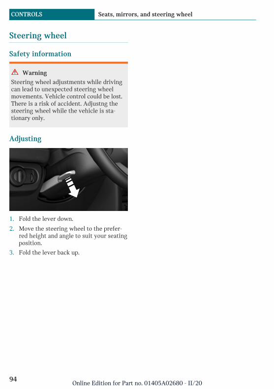
Steering wheel
Safety information
Warning
Steering wheel adjustments while drivingcan lead to unexpected steering wheelmovements. Vehicle control could be lost.There is a risk of accident. Adjustng thesteering wheel while the vehicle is sta-tionary only.
Adjusting
1. Fold the lever down.
2. Move the steering wheel to the prefer-red height and angle to suit your seatingposition.
3. Fold the lever back up.
Seite 94
CONTROLS Seats, mirrors, and steering wheel
94Online Edition for Part no. 01405A02680 - II/20

Transporting children safely
Vehicle features and options
This chapter describes all standard, country-specific and optional features offered withthe series. It also describes features andfunctions that are not necessarily availablein your vehicle, e.g., due to the selected op-tions or country versions. This also appliesto safety-related functions and systems.When using these functions and systems,the applicable laws and regulations must beobserved.
The right place for children
Safety information
Warning
Unattended children or animals in the ve-hicle can cause the vehicle to move andendanger themselves and traffic, for in-stance due to the following actions:
– Pressing the Start/Stop button.
– Releasing the parking brake.
– Opening and closing the doors orwindows.
– Engaging selector lever position N.
– Using vehicle equipment.
There is a risk of accidents or injuries. Donot leave children or animals unattendedin the vehicle. Take the vehicle key withyou when exiting and lock the vehicle.
Warning
A heated vehicle may result in death topersons, especially children, or animals.There is a risk of injuries or danger to life.Do not leave persons, especially children,or animals unattended in the vehicle.
Warning
Exposure to intense sunlight can causechild restraint systems and their compo-nents to become very hot. Persons maysustain burn injuries when touching thehot components. There is a risk of injury.Do not expose the child restraint system todirect sunlight or cover where necessary.If necessary, let the child restraint systemcool down before transporting a child. Donot leave children unattended in the vehi-cle.
Always transport children in therear seat
General informationAccident research shows that the safestplace for children is in the rear seat.
Transport children younger than 13 years ofage or shorter than 5 ft/150 cm only in therear seat in suitable child restraint systemsdesigned for the age, weight and size of thechild. Children 13 years of age or older mustwear a safety belt as soon as a suitable childrestraint system can no longer be used dueto their age, weight, or size.
Seite 95
Transporting children safely CONTROLS
95Online Edition for Part no. 01405A02680 - II/20
Safety information
Warning
The safety belt cannot be fastened cor-rectly on children shorter than 5 ft,150 cm without suitable additional childrestraint systems. The efficacy of safetygear, including safety belts, can be limitedor lost when safety belts are fastened in-correctly. An incorrectly fastened safetybelt can cause additional injuries, for in-stance in the event of an accident, brakingor evasive maneuvers. There is a risk of in-juries or danger to life. Secure childrenshorter than 5 ft, 150 cm using suitablechild restraint systems.
Children on the front passengerseat
General informationBefore using a child restraint system on thefront passenger seat, ensure that the front,knee, and side airbags on the front passen-ger side are deactivated. For automatic de-activation of front-seat passenger airbags,refer to page 143.
Safety information
Warning
Active front-seat passenger airbags can in-jure a child in a child restraint systemwhen the airbags are activated. There is arisk of injury. Make sure that the front-seat passenger airbags are deactivated andthat the PASSENGER AIRBAG OFF indica-tor light lights up.
Warning
The stability of the child restraint systemis limited or compromised with incorrectseat adjustment or improper installation ofthe child seat. There is a risk of injuries ordanger to life. Make sure that the child re-straint system fits securely against thebackrest. If possible, adjust the backresttilt for all affected backrests and correctlyadjust the seats. Make sure that seats andbackrests are securely engaged or locked.If possible, adjust the height of the headrestraints or remove them.
Installing child restraint sys-tems
General informationPay attention to the specifications of thechild restraint system manufacturer whenselecting, installing, and using child re-straint systems.
In order to facilitate the installation of aback-facing child restraint system in therear:
Move the front passenger seat as far up aspossible before folding down the backrest.
Safety information
Warning
The protective effect of child restraint sys-tems and their fastening systems whichhave been damaged or exposed to an acci-dent can be limited or lost. A child cannotbe properly restrained in the event of anaccident, braking or evasive maneuvers.There is a risk of injuries or danger to life.
Seite 96
CONTROLS Transporting children safely
96Online Edition for Part no. 01405A02680 - II/20

Do not use child restraint systems whichhave been damaged or exposed to an acci-dent.
If a child restraint system and its fasten-ing system has been damaged or exposedto an accident, have these systemschecked and replaced by the dealer's serv-ice center or another qualified service cen-ter or repair shop.
Warning
The stability of the child restraint systemis limited or compromised with incorrectseat adjustment or improper installation ofthe child seat. There is a risk of injuries ordanger to life. Make sure that the child re-straint system fits securely against thebackrest. If possible, adjust the backresttilt for all affected backrests and correctlyadjust the seats. Make sure that seats andbackrests are securely engaged or locked.If possible, adjust the height of the headrestraints or remove them.
On the rear seatsIn order to facilitate the installation of aback-facing child restraint system:
Move the front passenger seat as far up aspossible before folding down the backrest.
On the front passenger seat
Deactivating airbags
Warning
Active front-seat passenger airbags can in-jure a child in a child restraint systemwhen the airbags are activated. There is arisk of injury. Make sure that the front-seat passenger airbags are deactivated and
that the PASSENGER AIRBAG OFF indica-tor light lights up.
Before installing a child restraint system inthe front passenger seat, make sure that thefront, knee and side airbags on the frontpassenger side are deactivated.
Deactivate the front-seat passenger airbagsautomatically, refer to page 143.
Seat position and heightBefore installing a child restraint system,move the front passenger seat as far back aspossible and adjust its height to the highestand thus best possible position for the beltand to offer optimal protection in the eventof an accident.
If the upper anchorage of the safety belt islocated in front of the belt guide of the childseat, move the front passenger seat care-fully forward until the best possible beltguide position is reached.
Child seat security
The rear safety belts and the front passen-ger safety belt can be permanently locked tofasten child restraint systems.
Locking the safety belt1. Pull out the belt strap completely.
2. Secure the child restraint system withthe safety belt.
Seite 97
Transporting children safely CONTROLS
97Online Edition for Part no. 01405A02680 - II/20

3. Allow the belt strap to be pulled in andpull it tight against the child restraintsystem. The safety belt is locked.
Unlocking the safety belt1. Unbuckle the safety belt buckle.
2. Remove the child restraint system.
3. Allow the belt strap to be pulled in com-pletely.
LATCH child restraint fixingsystem
General informationLATCH: Lower Anchors and Tether for Chil-dren.
Pay attention to the operating and safety in-formation from the child restraint systemmanufacturer when installing and usingLATCH child restraint fixing systems.
Mounts for the lower LATCHanchorsThe lower anchors may be used to attachthe CRS to the vehicle seat up to a com-bined child and CRS weight of 65 lbs/30 kgwhen the child is restrained by the internalharnesses.
Safety information
Warning
If the LATCH child restraint fixing sys-tems are not correctly engaged, the protec-tive effect of the LATCH child restraintfixing system can be limited. There is arisk of injuries or danger to life. Make surethat the lower anchors are securely en-gaged and that the LATCH child restraint
fixing system fits securely against thebackrest.
Position
Symbol Meaning
The corresponding symbolshows the mounts for thelower LATCH anchors.
Seats equipped with loweranchors are marked with apair, (2), of LATCH symbols.
Before installing LATCH childrestraint fixing systemsPull the safety belt away from the area ofthe child restraint system.
Assembly of LATCH child restraintfixing systems1. Install child restraint system, see manu-
facturer's information.
2. Ensure that both LATCH anchors areproperly engaged.
Child restraint systems with tetherstrap
Safety information
Warning
If the upper retaining strap is incorrectlyused for the child restraint system, theprotective effect can be reduced. There isa risk of injury. Make sure that the upperretaining strap does not run over sharpedges and is not twisted as it passes theupper anchor.
Seite 98
CONTROLS Transporting children safely
98Online Edition for Part no. 01405A02680 - II/20
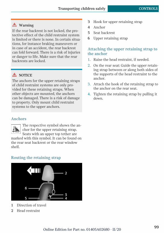
Warning
If the rear backrest is not locked, the pro-tective effect of the child restraint systemis limited or there is none. In certain situa-tions, for instance braking maneuvers orin case of an accident, the rear backrestcan fold forward. There is a risk of injuriesor danger to life. Make sure that the rearbackrests are locked.
NOTICE
The anchors for the upper retaining strapsof child restraint systems are only pro-vided for these retaining straps. Whenother objects are mounted, the anchorscan be damaged. There is a risk of damageto property. Only mount child restraintsystems to the upper anchors.
Anchors
The respective symbol shows the an-chor for the upper retaining strap.Seats with an upper top tether are
marked with this symbol. It can be found onthe rear seat backrest or the rear windowshelf.
Routing the retaining strap
1 Direction of travel
2 Head restraint
3 Hook for upper retaining strap
4 Anchor
5 Seat backrest
6 Upper retaining strap
Attaching the upper retaining strap tothe anchor1. Raise the head restraint, if needed.
2. On the rear seat: Guide the upper retain-ing strap between or along both sides ofthe supports of the head restraint to theanchor.
3. Attach the hook of the retaining strap tothe anchor on the rear seat.
4. Tighten the retaining strap by pulling itdown.
Seite 99
Transporting children safely CONTROLS
99Online Edition for Part no. 01405A02680 - II/20

Driving
Vehicle features and options
This chapter describes all standard, country-specific and optional features offered withthe series. It also describes features andfunctions that are not necessarily availablein your vehicle, e.g., due to the selected op-tions or country versions. This also appliesto safety-related functions and systems.When using these functions and systems,the applicable laws and regulations must beobserved.
Start/Stop button
ConceptPressing the Start/Stop buttonswitches standby state on oroff.
Drive-ready state is switchedon when you depress the
brake pedal while pressing the Start/Stopbutton.
Pressing the Start/Stop button againswitches drive-ready state back off andradio-ready state is switched back on.
The drive-ready state cannot be activated aslong as the charging cable is connected, re-fer to page 218.
Radio-ready stateSome electronic systems/power consumersare ready for operation.
The radio-ready state is switched off auto-matically:
– If the driver's or front passenger door isopened when exiting the vehicle, withdrive-ready state switched off manually.
– After approx. 8 minutes.
– When the vehicle is locked using thecentral locking system.
– If the charge state of the batteries islow.
Radio-ready state remains active if, for in-stance drive-ready state is automaticallyswitched off for the following reasons:
– Opening or closing the driver's door.
– Unfastening of the driver's safety belt.
– When automatically switching from lowbeams to parking lights.
Radio-ready state is also switched back onif the on/off button on the radio is pressedwhen the vehicle is parked.
If drive-ready state is switched on: the sys-tem automatically switches to radio-readystate when the driver's door is opened andthe driver's safety belt is unbuckled if thelights are switched off or the daytime run-ning lights are switched on.
Standby stateAll electronic systems/power consumers areready for operation. Odometer and trip od-ometer are displayed in the instrument clus-ter.
To preserve the battery, use standby stateand activated power features only as long asabsolutely necessary.
Turning on standby statePressing the Start/Stop button switchesstandby state on or off.
Standby state is switched off automatically:
Seite 100
CONTROLS Driving
100Online Edition for Part no. 01405A02680 - II/20

– When locking the vehicle, even if thelow beams are switched on.
– When opening or closing the driverdoor, if the driver's safety belt is un-buckled and the low beams are switchedoff.
– While the driver's safety belt is unbuck-led with driver's door open and lowbeams off.
– When the batteries' state of charge islow, if the low beams are switched off.
– The low beams switch to parking lightsafter approx. 15 minutes of no use.
– When the front doors are opened ifthere is no other person sitting in thefront seats.
Drive-ready stateActivated drive-ready state is the equiva-lent of a running engine in conventional ve-hicles. Deactivated drive-ready state isequivalent to switching the engine off.
If drive-ready state is switched on, the vehi-cle ready to drive and the pointer in the in-strument cluster is on READY signal, referto page 101.
All vehicle systems are ready for operation.
Most of the indicator/warning lights in theinstrument cluster light up for a variedlength of time.
To save battery power when parking, switchoff drive-ready state and any unnecessaryelectronic systems/power consumers.
The drive-ready state is switched off auto-matically if the driver's safety belt is notbuckled when the driver's door is opened.
Safety information
NOTICE
Selector lever position P is automaticallyengaged when drive-ready state isswitched off. There is a risk of damage toproperty. Do not switch drive-ready stateoff in vehicle washes.
Drive-ready state in detail
Safety information
Warning
An unsecured vehicle can begin to moveand possibly roll away. There is a risk ofaccident. Before exiting, secure the vehi-cle against rolling.
In order to ensure that the vehicle is se-cured against rolling away, follow the fol-lowing:
– Set the parking brake.
– On uphill grades or on a downhillslope, turn the front wheels in the di-rection of the curb.
– On uphill grades or on a downhillslope, also secure the vehicle, for in-stance with a wheel chock.
Switching on drive-ready state1. Close the driver's door.
2. Depress the brake pedal.
3. Press the Start/Stop button.
Drive-ready state is switched on.
Seite 101
Driving CONTROLS
101Online Edition for Part no. 01405A02680 - II/20
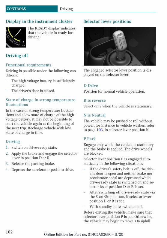
Display in the instrument clusterThe READY display indicatesthat the vehicle is ready fordriving.
Driving off
Functional requirementsDriving is possible under the following con-ditions:
– The high-voltage battery is sufficientlycharged.
– The driver's door is closed.
State of charge in strong temperaturefluctuationsIn the case of strong temperature fluctua-tions and a low state of charge of the high-voltage battery, it may not be possible tostart the vehicle again at the beginning ofthe next trip. Recharge vehicle with lowstate of charge in time.
Driving1. Switch on drive-ready state.
2. Apply the brake and engage the selectorlever in position D or R.
3. Release the parking brake.
4. Depress the accelerator pedal to drive.
Selector lever positions
The engaged selector lever position is dis-played on the selector lever.
D DrivePosition for normal vehicle operation.
R is reverseSelect only when the vehicle is stationary.
N is NeutralThe vehicle may be pushed or roll withoutpower, for instance in vehicle washes, referto page 103, in selector lever position N.
P ParkEngage only while the vehicle is stationaryand the brake is applied. The drive wheelsare blocked.
Selector lever position P is engaged auto-matically in the following situations:
– If the driver's safety belt is off, the driv-er's door is open and neither brake noraccelerator pedal are depressed whiledrive-ready state is switched on and se-lector lever position D or R is set.
– After switching off drive-ready state viathe Start/Stop button, if selector leverposition D or R is set.
– With standby state switched off.
Before exiting the vehicle, make sure thatselector lever position P is set. Otherwise,the vehicle may begin to move. On uphill
Seite 102
CONTROLS Driving
102Online Edition for Part no. 01405A02680 - II/20

grades, also Set parking brake, refer topage 107.
Engaging selector lever positions
General information– Interlock: the selector lever position P
can be exited only with drive-readystate engaged.
– Shift lock: with the vehicle stationary,press on the brake pedal before shiftingout of P or N; otherwise, the shift com-mand will not be executed.
– Shift lock: before shifting out of P, re-move the charging cable from the vehi-cle; otherwise, the shift command willnot be executed.
Engage D, N, RA selector lever lock prevents the followingfaulty operation:
– Unintentional shifting into selectorlever position R.
– Unintentional shifting from selectorlever position P into another selectorlever position.
1. Press and hold the button to release theselector lever lock.
2. With the driver's safety belt fastened,briefly push the selector lever in the de-sired direction, past a resistance point,if needed. The selector lever automati-
cally returns to the center position whenreleased.
Engaging P
Press button P.
Rolling or pushing the vehicle
General informationIn some situations, the vehicle is to rollwithout its own power for a short distance,for instance in a car wash, or be pushed.
Engaging selector lever position N1. Switch on drive-ready state while press-
ing on the brake pedal.
2. If necessary, release the parking brake.
3. Depress the brake pedal.
4. Engage selector lever position N.
5. Switch off drive-ready state.
In this way, standby state remainsswitched on, and a Check Control mes-sage is displayed.
Seite 103
Driving CONTROLS
103Online Edition for Part no. 01405A02680 - II/20
The vehicle can roll.
NOTICE
Selector lever position P is automaticallyengaged when standby state is switchedoff. There is a risk of damage to property.Do not switch standby state off in vehiclewashes.
Irrespective of standby state, the selectorlever position P is automatically engaged af-ter approx. 15 minutes.
If there is a malfunction, you may not beable to change the selector lever position.
Electronically unlock the transmission lock,if needed.
Electronic unlocking of thetransmission lock
General informationElectronically unlock the transmission lockto maneuver vehicle from a danger area.
Before unlocking the transmission lock, setthe parking brake to prevent the vehiclefrom rolling away.
Engaging selector lever position N1. Hold the Start/Stop button pressed.
2. Depress the brake pedal.
3. Press and hold the selector lever in posi-tion N.
A corresponding Check Control messageis displayed.
4. Press the selector lever again into posi-tion N within approx. 2 seconds.
Position N is indicated on the selectorlever.
5. Release Start/Stop button and brake.
6. Maneuver the vehicle from the dangerarea and secure it against moving on itsown.
Switching off drive-ready statePark the vehicle. Noises from the electricalsystem such as for cooling the high-voltagesystem might still be audible.
After stopping the vehicle:
1. Apply brake and engage the selectorlever in position P.
2. Set the parking brake.
3. Press the Start/Stop button.
The READY indicator goes out and asignal sounds.
In case of longer idle times, follow theinstructions in the Care chapter, refer topage 266.
Driving in detail: eDRIVE
Safety information
DANGER
The braking power of the electric motorcan be stronger than for a vehicle withcombustion engine. Abrupt braking andslow-down may confuse other traffic.There is a risk of accident. Carefully re-lease the accelerator pedal. Adjust drivingstyle to traffic conditions. Watch trafficclosely and actively intervene where ap-propriate.
Seite 104
CONTROLS Driving
104Online Edition for Part no. 01405A02680 - II/20

Warning
When driving in electric mode, pedes-trians and other traffic might pay less at-tention to the vehicle due to the lack ofengine noise. There is a risk of accident.Adjust driving style to traffic conditions.Watch traffic closely and actively inter-vene where appropriate.
Warning
Without energy recovery, there is no brak-ing power of the electric motor available.The vehicle could roll further than antici-pated. There is a risk of accident. Adjustdriving style to traffic conditions. Watchtraffic closely and actively intervenewhere appropriate.
Accelerator pedal positions
1 Deceleration
2 Coasting
3 Acceleration or constant speed: ePO-WER
DecelerationReleasing the accelerator pedal causes de-celeration similar to cautious braking. Addi-tionally, the brake lights will come on with-out hitting the brakes.
The degree of the deceleration depends onthe energy recovery, refer to page 106, set-ting.
During the deceleration, energy is recov-ered and the high-voltage battery ischarged.
Energy recovery: CHARGEThe high-voltage battery is recharged inpart through energy recovery. The electricmotor acts as a generator when deceleratingand converts the kinetic energy into electri-cal energy.
Energy can be recovered if the followingconditions are met:
– The vehicle is moving.
– Speed higher than approx.12 mph/20 km/h.
– Selector lever position D or R is set.
– Accelerator pedal is not actuated or onlypressed down one third of the way.
Energy cannot be recovered in the followingsituations:
– Selector lever position N is engaged.
– While drive stability control systems,for instance DTC, are active and control-ling the vehicle, even though this is notindicated by an indicator light.
– The high-voltage battery is fullycharged.
– When temperature of the high-voltagebattery is very low or very high.
In winter it might be possible that theenergy recovery is temporarily unavaila-ble after startup.
Exemplary traffic situationsIf a deceleration operation is foreseeablewhile driving, this can be used for energyrecovery.
The following exemplary driving situationsmay be suitable:
Seite 105
Driving CONTROLS
105Online Edition for Part no. 01405A02680 - II/20

– Decelerating downhill.
– Deceleration before a red light.
Avoid late or abrupt braking. Instead, decel-erate the vehicle using energy recovery.
Set energy recovery
ConceptThe energy recovery is adjustable.
– High energy recovery: the vehicle decel-erates faster, more energy is returned tothe high-voltage battery.
– Low energy recovery: the vehicle decel-erates more slowly, less energy is re-turned to the high-voltage battery.
Overview
Energy recovery
Adjusting
Press the button up or down.
– LED off: high energy recovery.
– LED illuminated: low energy recovery.
The setting is displayed in the instrumentcluster.
CoastingThe electric drive makes it possible to rollwithout consuming energy. This drivingcondition is referred to as coasting.
Proactive driving reduces energy consump-tion and increases the range.
With vehicle rolling, no energy is recov-ered.
Exemplary traffic situationsIf a route can be traveled without antici-pated need for braking, it is advantageousto roll.
The following exemplary driving situationsmay be suitable:
– Rolling on a straight downhill routewithout obstacles.
– Coasting on a route without obstacles.
Avoid late or abrupt braking.
Acoustic pedestrian protectionThe system generates a continuous drivingnoise during electric driving up to approx.20 mph/30 km/h.
A speaker system broadcasts the noise tothe surroundings.
As a result, other road users, for instancepedestrians or cyclists, can better perceivethe vehicle.
Heavily discharged high-voltagebatteryIf the high-voltage battery is heavily dis-charged during the trip, the performanceand some comfort features are reducedstep-by-step to extend the range.
Heated high-voltage battery
With a stationary vehicleIn isolated cases, when the vehicle is sta-tionary, it is possible for the high-voltagebattery to overheat, for instance, as a resultof extreme hot or cold temperatures or di-rect sunlight. Drive-ready state cannot be
Seite 106
CONTROLS Driving
106Online Edition for Part no. 01405A02680 - II/20
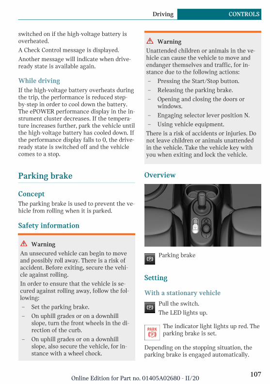
switched on if the high-voltage battery isoverheated.
A Check Control message is displayed.
Another message will indicate when drive-ready state is available again.
While drivingIf the high-voltage battery overheats duringthe trip, the performance is reduced step-by-step in order to cool down the battery.The ePOWER performance display in the in-strument cluster decreases. If the tempera-ture increases further, park the vehicle untilthe high-voltage battery has cooled down. Ifthe performance display falls to 0, the drive-ready state is switched off and the vehiclecomes to a stop.
Parking brake
ConceptThe parking brake is used to prevent the ve-hicle from rolling when it is parked.
Safety information
Warning
An unsecured vehicle can begin to moveand possibly roll away. There is a risk ofaccident. Before exiting, secure the vehi-cle against rolling.
In order to ensure that the vehicle is se-cured against rolling away, follow the fol-lowing:
– Set the parking brake.
– On uphill grades or on a downhillslope, turn the front wheels in the di-rection of the curb.
– On uphill grades or on a downhillslope, also secure the vehicle, for in-stance with a wheel chock.
Warning
Unattended children or animals in the ve-hicle can cause the vehicle to move andendanger themselves and traffic, for in-stance due to the following actions:
– Pressing the Start/Stop button.
– Releasing the parking brake.
– Opening and closing the doors orwindows.
– Engaging selector lever position N.
– Using vehicle equipment.
There is a risk of accidents or injuries. Donot leave children or animals unattendedin the vehicle. Take the vehicle key withyou when exiting and lock the vehicle.
Overview
Parking brake
Setting
With a stationary vehicle
Pull the switch.
The LED lights up.
The indicator light lights up red. Theparking brake is set.
Depending on the stopping situation, theparking brake is engaged automatically.
Seite 107
Driving CONTROLS
107Online Edition for Part no. 01405A02680 - II/20

In some parking situations, the parkingbrake is automatically engaged, when selec-tor lever position P is engaged. In thesecases, the parking brake is released auto-matically when you leave the selector leverposition P.
While drivingTo use as emergency brake while driving:
Pull the switch and hold it. The vehiclebrakes hard while the switch is beingpulled.
The indicator light lights up red, asignal sounds and the brake lightslight up.
A Check Control message is displayed.
If the vehicle is decelerated to a completestop, the parking brake is engaged.
Releasing
Releasing manually1. Switch on standby state.
2. Press the switch while stepping onthe brake pedal or selector lever posi-tion P is set.
The LED and indicator light go out.
The parking brake is released.
Automatic releaseFor automatic release, step on the accelera-tor pedal.
The LED and indicator light go out.
The parking brake is automatically releasedwhen you step on the accelerator pedal un-der the following conditions:
– Standby state switched on.
– Drive mode engaged.
– Driver buckled in and doors closed.
MalfunctionIf the parking brake fails or malfunctions,secure the vehicle against rolling before ex-iting.
A Check Control message is displayed.
Secure the vehicle against rolling away, forinstance with a wheel chock, after exitingthe vehicle.
After a power failure
Re-activating the parking brake1. Switch on standby state.
2. Press the switch while stepping onthe brake pedal or selector lever posi-tion P is set.
It may take several seconds for the brake tobe reactivated. Some mechanical sounds as-sociated with this process are normal.
The indicator light in the instrumentcluster goes out as soon as the park-ing brake is ready for operation.
Hold function
ConceptThe system holds the vehicle automaticallywhen gear is engaged. This prevents rollingagainst the direction of travel.
In selector lever position D, the vehicle can-not roll backwards. In selector lever posi-tion R, it cannot roll forward. The brakepedal does not have to be pressed.
Reducing energy consumptionTo reduce energy consumption when thehold function is activated, activate the park-ing brake or engage the selector lever in po-sition P when the vehicle is stopped forlong periods of time.
Seite 108
CONTROLS Driving
108Online Edition for Part no. 01405A02680 - II/20

The hold function can be affected by the ve-hicle's load and the road incline. If needed, aCheck Control message will appear and po-sition P will be selected automatically.
Turn signal, high beams, head-light flasher
Turn signal
Using turn signals
Press the lever past the resistance point.
Canada: the lever returns into its startingposition after actuation. To switch off man-ually, slightly tap the lever to the resistancepoint.
Triple turn signal activationLightly tap the lever up or down.
The triple turn signal duration can be ad-justed.
Via the Central Information Display (CID):
1. "My MINI"
2. "Vehicle settings"
3. "Lighting"
4. "Exterior lighting"
5. "One-touch turn signal"
6. Select the desired setting.
Settings are stored for the profile currentlyused.
Signaling brieflyPress the lever to the resistance point andhold it there for as long as you want theturn signal to flash.
MalfunctionUnusually rapid flashing of the indicatorlight indicates that a turn signal bulb hasfailed.
High beams, headlight flasherPush the lever forward or pull it backward.
– High beams on, arrow 1.
The high beams light up when the lowbeams are switched on.
– High beams off/headlight flasher, ar-row 2.
Wiper system
General informationDo not use the wipers if the windshield isdry, as this may damage the wiper blades orcause them to become worn more quickly.
Seite 109
Driving CONTROLS
109Online Edition for Part no. 01405A02680 - II/20

Safety information
Warning
If the wipers start moving in the foldedaway state, body parts can be jammed ordamage may occur to parts of the vehicle.There is a risk of injury or risk of damageto property. Make sure that the vehicle isswitched off when the wipers are in thefolded away state and the wipers arefolded in when switching on.
NOTICE
If the wipers are frozen to the windshield,the wiper blades can be torn off and thewiper motor can overheat when switchingon. There is a risk of damage to property.Defrost the windshield prior to switchingthe wipers on.
Switching on
Press the lever up until the desired positionis reached.
– Resting position of the wipers, posi-tion 0.
– Intermittent operation or rain sensor,position 1.
– Normal wiper speed, position 2.
– Fast wiper speed, position 3.
When travel is interrupted with the wipersystem switched on: when travel continues,the wipers resume at their previous speed.
Switching off and brief wipe
Press the lever down.
– Switching off: press the lever down untilit reaches its standard position.
– Brief wipe: press the lever down fromthe standard position.
The lever automatically returns to its in-itial position when released.
Interval mode or rain sensor
ConceptThe rain sensor automatically controls thetime between wipes depending on the in-tensity of the rainfall.
General informationThe sensor is located on the windshield, di-rectly in front of the interior mirror. With-out the rain sensor, the frequency of thewiper operation is preset.
Seite 110
CONTROLS Driving
110Online Edition for Part no. 01405A02680 - II/20

Safety information
NOTICE
If the rain sensor is activated, the wiperscan accidentally start moving in vehiclewashes. There is a risk of damage to prop-erty. Deactivate the rain sensor in vehiclewashes.
Activating
Press the lever up once from its standardposition, arrow 1.
Wiping is started.
The LED in the wiper lever is illuminated.
In frosty conditions, wiper operation maynot start.
DeactivatingPress the lever back into the standard posi-tion.
Setting the frequency or sensitivity ofthe rain sensor
Turn the thumbwheel.
With deactivated rain sensor: set the inter-val.
With activated rain sensor: set the rain sen-sor sensitivity.
Up: short interval or high sensitivity of therain sensor.
Down: long interval or low sensitivity of therain sensor.
Windshield washer system
Safety information
Warning
The washer fluid can freeze onto the win-dow at low temperatures and obstruct theview. There is a risk of accident. Only usethe washer systems, if the washer fluidcannot freeze. Use washer fluid with anti-freeze, if needed.
NOTICE
When the washer fluid reservoir is empty,the wash pump cannot work as intended.There is a risk of damage to property. Donot use the washer system when thewasher fluid reservoir is empty.
Seite 111
Driving CONTROLS
111Online Edition for Part no. 01405A02680 - II/20

Cleaning the windshield
Pull the lever.
The system sprays washer fluid on thewindshield and activates the wipers briefly.
Windshield washer nozzlesThe windshield washer nozzles are auto-matically heated while standby state isswitched on.
Rear window wiper
Overview
Switching onTurn the outer switch upward.
– Resting position of the wiper, posi-tion 0.
– Intermittent mode, arrow 1. When re-verse gear is engaged, the systemswitches to continuous operation.
Clean the rear windowTurn the outer switch in the desired direc-tion.
– In resting position: turn the switchdownward, arrow 3. The switch auto-matically returns to its idle positionwhen released.
– In intermittent mode: turn the switchfurther, arrow 2. The switch automati-cally returns to its interval positionwhen released.
The function is deactivated if the washerfluid reservoir level is low.
Fold-away position of the wipers
ConceptThe fold-away position enables the wipersto be folded away from the windshield.
General informationHelpful when changing the wiper blades orunder frosty conditions, for instance.
Safety information
Warning
If the wipers start moving in the foldedaway state, body parts can be jammed ordamage may occur to parts of the vehicle.There is a risk of injury or risk of damageto property. Make sure that the vehicle isswitched off when the wipers are in thefolded away state and the wipers arefolded in when switching on.
NOTICE
If the wipers are frozen to the windshield,the wiper blades can be torn off and thewiper motor can overheat when switchingon. There is a risk of damage to property.
Seite 112
CONTROLS Driving
112Online Edition for Part no. 01405A02680 - II/20

Defrost the windshield prior to switchingthe wipers on.
Folding away the wipers1. Switch standby state on and off again.
2. Press and hold the wiper lever down, un-til the wipers stop in a close to verticalposition.
3. Fold the wipers all the way away fromthe windshield.
Folding down the wipersAfter the wipers are folded back down, thewiper system must be reactivated.
1. Fold the wipers back down onto thewindshield.
2. Switch on standby state.
3. Push wiper lever down. Wipers returnto their resting position and are readyagain for operation.
Canada: wiper system
General informationDo not use the wipers if the windshield isdry, as this may damage the wiper blades orcause them to become worn more quickly.
Safety information
Warning
If the wipers start moving in the foldedaway state, body parts can be jammed ordamage may occur to parts of the vehicle.There is a risk of injury or risk of damageto property. Make sure that the vehicle isswitched off when the wipers are in thefolded away state and the wipers arefolded in when switching on.
NOTICE
If the wipers are frozen to the windshield,the wiper blades can be torn off and thewiper motor can overheat when switchingon. There is a risk of damage to property.Defrost the windshield prior to switchingthe wipers on.
Switching on
Tap up the lever or press it past the resist-ance point.
– Normal wiper speed: tap up once.
Seite 113
Driving CONTROLS
113Online Edition for Part no. 01405A02680 - II/20
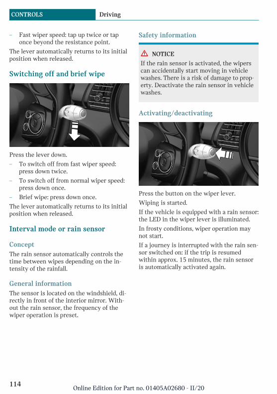
– Fast wiper speed: tap up twice or taponce beyond the resistance point.
The lever automatically returns to its initialposition when released.
Switching off and brief wipe
Press the lever down.
– To switch off from fast wiper speed:press down twice.
– To switch off from normal wiper speed:press down once.
– Brief wipe: press down once.
The lever automatically returns to its initialposition when released.
Interval mode or rain sensor
ConceptThe rain sensor automatically controls thetime between wipes depending on the in-tensity of the rainfall.
General informationThe sensor is located on the windshield, di-rectly in front of the interior mirror. With-out the rain sensor, the frequency of thewiper operation is preset.
Safety information
NOTICE
If the rain sensor is activated, the wiperscan accidentally start moving in vehiclewashes. There is a risk of damage to prop-erty. Deactivate the rain sensor in vehiclewashes.
Activating/deactivating
Press the button on the wiper lever.
Wiping is started.
If the vehicle is equipped with a rain sensor:the LED in the wiper lever is illuminated.
In frosty conditions, wiper operation maynot start.
If a journey is interrupted with the rain sen-sor switched on: if the trip is resumedwithin approx. 15 minutes, the rain sensoris automatically activated again.
Seite 114
CONTROLS Driving
114Online Edition for Part no. 01405A02680 - II/20

Setting the frequency or sensitivity ofthe rain sensor
Turn the thumbwheel.
With deactivated rain sensor: set the inter-val.
With activated rain sensor: set the rain sen-sor sensitivity.
Up: short interval or high sensitivity of therain sensor.
Down: long interval or low sensitivity of therain sensor.
Windshield washer system
Safety information
Warning
The washer fluid can freeze onto the win-dow at low temperatures and obstruct theview. There is a risk of accident. Only usethe washer systems, if the washer fluidcannot freeze. Use washer fluid with anti-freeze, if needed.
NOTICE
When the washer fluid reservoir is empty,the wash pump cannot work as intended.There is a risk of damage to property. Donot use the washer system when thewasher fluid reservoir is empty.
Cleaning the windshield
Pull the lever.
The system sprays washer fluid on thewindshield and activates the wipers briefly.
Windshield washer nozzlesThe windshield washer nozzles are auto-matically heated while standby state isswitched on.
Rear window wiper
Overview
Switching onTurn the outer switch upward.
– Resting position of the wiper, posi-tion 0.
– Intermittent mode, arrow 1. When re-verse gear is engaged, the systemswitches to continuous operation.
Seite 115
Driving CONTROLS
115Online Edition for Part no. 01405A02680 - II/20
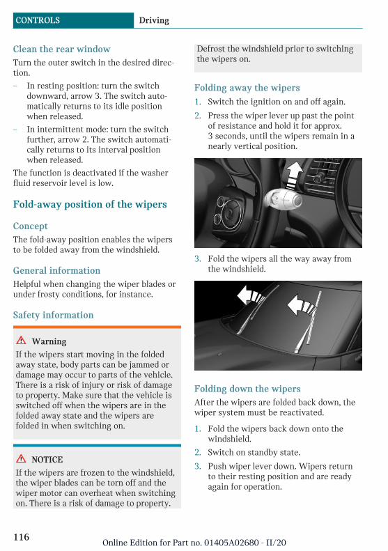
Clean the rear windowTurn the outer switch in the desired direc-tion.
– In resting position: turn the switchdownward, arrow 3. The switch auto-matically returns to its idle positionwhen released.
– In intermittent mode: turn the switchfurther, arrow 2. The switch automati-cally returns to its interval positionwhen released.
The function is deactivated if the washerfluid reservoir level is low.
Fold-away position of the wipers
ConceptThe fold-away position enables the wipersto be folded away from the windshield.
General informationHelpful when changing the wiper blades orunder frosty conditions, for instance.
Safety information
Warning
If the wipers start moving in the foldedaway state, body parts can be jammed ordamage may occur to parts of the vehicle.There is a risk of injury or risk of damageto property. Make sure that the vehicle isswitched off when the wipers are in thefolded away state and the wipers arefolded in when switching on.
NOTICE
If the wipers are frozen to the windshield,the wiper blades can be torn off and thewiper motor can overheat when switchingon. There is a risk of damage to property.
Defrost the windshield prior to switchingthe wipers on.
Folding away the wipers1. Switch the ignition on and off again.
2. Press the wiper lever up past the pointof resistance and hold it for approx.3 seconds, until the wipers remain in anearly vertical position.
3. Fold the wipers all the way away fromthe windshield.
Folding down the wipersAfter the wipers are folded back down, thewiper system must be reactivated.
1. Fold the wipers back down onto thewindshield.
2. Switch on standby state.
3. Push wiper lever down. Wipers returnto their resting position and are readyagain for operation.
Seite 116
CONTROLS Driving
116Online Edition for Part no. 01405A02680 - II/20

Washer fluid
General informationAll washer nozzles are supplied from onereservoir.
Use a mixture of tap water and windshieldwasher concentrate. If desired, a windshieldwasher concentrate containing antifreezecan be used.
Recommended minimum fill quantity:0.2 US gal/1 liter.
Safety information
Warning
Some antifreeze agents can contain harm-ful substances and are flammable. There isa risk of fire and a risk of injury. Followthe instructions on the containers. Keepantifreeze away from ignition sources. Donot refill operating materials into differentbottles. Store operating materials out ofreach of children.
United States: the washer fluid mixture ra-tio is regulated by the U.S. EPA and manyindividual states; do not exceed the allow-able washer fluid dilution ratio limits thatapply. Follow the usage instructions on thewasher fluid container.
Use of BMW’s Windshield Washer Con-centrate or the equivalent is recom-mended.
NOTICE
Silicon-containing additives in the washerfluid for the water-repelling effect on thewindows can lead to damage to the wash-ing system. There is a risk of damage toproperty. Do not add silicon-containing ad-ditives to the washer fluid.
NOTICE
Mixing different windshield washer con-centrates or antifreeze can damage thewashing system. There is a risk of damageto property. Do not mix different wind-shield washer concentrates or antifreeze.Follow the information and mixing ratiosprovided on the containers.
Overview
The washer fluid reservoir is located in theengine compartment.
MalfunctionThe use of undiluted windshield washerconcentrate or alcohol-based antifreeze canlead to incorrect readings at temperaturesbelow +5 ℉/-15 ℃.
Seite 117
Driving CONTROLS
117Online Edition for Part no. 01405A02680 - II/20
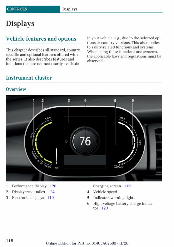
Displays
Vehicle features and options
This chapter describes all standard, country-specific and optional features offered withthe series. It also describes features andfunctions that are not necessarily available
in your vehicle, e.g., due to the selected op-tions or country versions. This also appliesto safety-related functions and systems.When using these functions and systems,the applicable laws and regulations must beobserved.
Instrument cluster
Overview
1 Performance display 120
2 Display/reset miles 124
3 Electronic displays 119
Charging screen 119
4 Vehicle speed
5 Indicator/warning lights
6 High-voltage battery charge indica-tor 120
Seite 118
CONTROLS Displays
118Online Edition for Part no. 01405A02680 - II/20
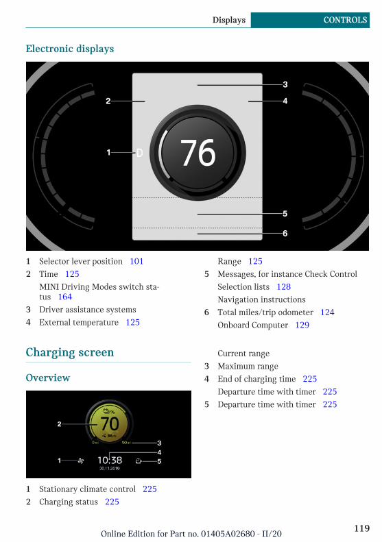
Electronic displays
1 Selector lever position 101
2 Time 125
MINI Driving Modes switch sta-tus 164
3 Driver assistance systems
4 External temperature 125
Range 125
5 Messages, for instance Check Control
Selection lists 128
Navigation instructions
6 Total miles/trip odometer 124
Onboard Computer 129
Charging screen
Overview
1 Stationary climate control 225
2 Charging status 225
Current range
3 Maximum range
4 End of charging time 225
Departure time with timer 225
5 Departure time with timer 225
Seite 119
Displays CONTROLS
119Online Edition for Part no. 01405A02680 - II/20
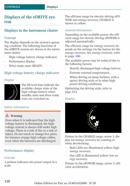
Displays of the eDRIVE sys-tem
Displays in the instrument cluster
ConceptThe display depends on the system's operat-ing condition. The following functions ofthe eDRIVE system are shown in the instru-ment cluster
– High-voltage battery charge indicator.
– Performance display.
– Drive-ready state: READY.
High-voltage battery charge indicator
Display
The fill level bars indicate theavailable charge state of thehigh-voltage battery whenstandby state and drive-readystate are switched on.
Safety information
Warning
Even when it is indicated that the high-voltage battery is discharged, the high-voltage system is always still under highvoltage. There is a risk of fire or a risk ofinjury. Do not touch or change live parts,for instance orange high-voltage cables,even when the batteries are discharged.
Performance display
Concept
A pointer indicates the power output in ascale.
The efficient range for electric driving ePO-WER and energy recovery CHARGE isshown in yellow.
General information
Depending on the available power, the effi-cient range for electric driving ePOWER isadjusted automatically.
The efficient range for energy recovery de-pends on the settings via the button for theenergy recovery. Set energy recovery, referto page 106.
The available power may be reduced due tothe following factors:
– Heavily discharged high-voltage battery.
– Extreme external temperatures.
– When driving on steep inclines, with asporty driving style or in other high-power driving conditions.
Optimizing the driving style, refer topage 213.
Display
Pointer in the CHARGE range, arrow 1: dis-play for energy recovery by coasting orwhen decelerating:
– Both LEDs are illuminated yellow: highenergy recovery.
– One LED is illuminated yellow: low en-ergy recovery.
Pointer in the ePOWER range, arrow 2: effi-cient acceleration.
Seite 120
CONTROLS Displays
120Online Edition for Part no. 01405A02680 - II/20
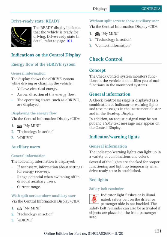
Drive-ready state: READY
The READY display indicatesthat the vehicle is ready fordriving. Drive-ready state indetail, refer to page 101.
Indications on the Control Display
Energy flow of the eDRIVE system
General information
The display shows the eDRIVE systemwhile driving or charging the vehicle:
– Yellow: electrical energy.
– Arrow: direction of the energy flow.
– The operating states, such as eDRIVE,are displayed.
Displaying the energy flow
Via the Central Information Display (CID):
1. "My MINI"
2. "Technology in action"
3. "eDRIVE"
Auxiliary users
General information
The following information is displayed:
– If necessary, information about settingsfor energy recovery.
– Range potential when switching off in-dividual auxiliary users.
– Current range.
With split screen: show auxiliary user
Via the Central Information Display (CID):
1. "My MINI"
2. "Technology in action"
3. "eDRIVE"
Without split screen: show auxiliary user
Via the Central Information Display (CID):
1. "My MINI"
2. "Technology in action"
3. "Comfort information"
Check Control
ConceptThe Check Control system monitors func-tions in the vehicle and notifies you of mal-functions in the monitored systems.
General informationA Check Control message is displayed as acombination of indicator or warning lightsand text messages in the instrument clusterand in the Head-up Display.
In addition, an acoustic signal may be out-put and a SMS text message may appear onthe Control Display.
Indicator/warning lights
General informationThe indicator/warning lights can light up ina variety of combinations and colors.
Several of the lights are checked for properfunctioning and light up temporarily whendrive-ready state is established.
Red lights
Safety belt reminder
Indicator light flashes or is illumi-nated: safety belt on the driver orpassenger side is not buckled. The
safety belt reminder can also be activated ifobjects are placed on the front passengerseat.
Seite 121
Displays CONTROLS
121Online Edition for Part no. 01405A02680 - II/20
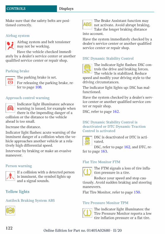
Make sure that the safety belts are posi-tioned correctly.
Airbag system
Airbag system and belt tensionermay not be working.
Have the vehicle checked immedi-ately by a dealer's service center or anotherqualified service center or repair shop.
Parking brake
The parking brake is set.
For releasing the parking brake, re-fer to page 108.
Approach control warning
Indicator light illuminates: advancewarning is issued, for example whenthere is the impending danger of a
collision or the distance to the vehicleahead is too small.
Increase the distance.
Indicator light flashes: acute warning of theimminent danger of a collision when the ve-hicle approaches another vehicle at a rela-tively high differential speed.
Intervene by braking or make an evasivemaneuver.
Person warning
If a collision with a detected personis imminent, the symbol lights upand a signal sounds.
Yellow lights
Antilock Braking System ABS
The Brake Assistant function maynot activate. Avoid abrupt braking.Take the longer braking distance
into account.
Have the system immediately checked by adealer's service center or another qualifiedservice center or repair shop.
DSC Dynamic Stability Control
The indicator light flashes: DSC con-trols the drive and braking forces.The vehicle is stabilized. Reduce
speed and modify your driving style to thedriving circumstances.
The indicator light lights up: DSC has mal-functioned.
Have the system checked by a dealer's serv-ice center or another qualified service cen-ter or repair shop.
DSC, refer to page 162.
DSC Dynamic Stability Control isdeactivated or DTC Dynamic TractionControl is activated
DSC is deactivated or DTC is acti-vated.
DSC, refer to page 162, and DTC, re-fer to page 163.
Flat Tire Monitor FTM
The FTM signals a loss of tire infla-tion pressure in a tire.
Reduce your speed and stop cau-tiously. Avoid sudden braking and steeringmaneuvers.
Flat Tire Monitor, refer to page 150.
Tire Pressure Monitor TPM
The indicator light illuminates: theTire Pressure Monitor reports a lowtire inflation pressure or a flat tire.
Seite 122
CONTROLS Displays
122Online Edition for Part no. 01405A02680 - II/20
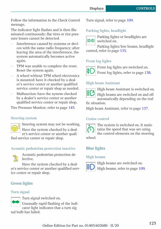
Follow the information in the Check Controlmessage.
The indicator light flashes and is then illu-minated continuously: flat tires or tire pres-sure losses cannot be detected.
– Interference caused by systems or devi-ces with the same radio frequency: afterleaving the area of the interference, thesystem automatically becomes activeagain.
– TPM was unable to complete the reset.Reset the system again.
– A wheel without TPM wheel electronicsis mounted: have it checked by a deal-er’s service center or another qualifiedservice center or repair shop as needed.
– Malfunction: have the system checkedby a dealer’s service center or anotherqualified service center or repair shop.
Tire Pressure Monitor, refer to page 145.
Steering system
Steering system may not be working.
Have the system checked by a deal-er's service center or another quali-
fied service center or repair shop.
Acoustic pedestrian protection inactive
Acoustic pedestrian protection de-fective.
Have the system checked by a deal-er's service center or another qualified serv-ice center or repair shop.
Green lights
Turn signal
Turn signal switched on.
Unusually rapid flashing of the indi-cator light indicates that a turn sig-
nal bulb has failed.
Turn signal, refer to page 109.
Parking lights, headlight
Parking lights or headlights areswitched on.
Parking lights/low beams, headlightcontrol, refer to page 135.
Front fog lights
Front fog lights are switched on.
Front fog lights, refer to page 138.
High-beam Assistant
High-beam Assistant is switched on.
High beams are switched on and offautomatically depending on the traf-
fic situation.
High-beam Assistant, refer to page 137.
Cruise control
The system is switched on. It main-tains the speed that was set usingthe control elements on the steering
wheel.
Blue lights
High beams
High beams are switched on.
High beams, refer to page 109.
Seite 123
Displays CONTROLS
123Online Edition for Part no. 01405A02680 - II/20
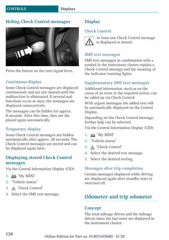
Hiding Check Control messages
Press the button on the turn signal lever.
Continuous displaySome Check Control messages are displayedcontinuously and are not cleared until themalfunction is eliminated. If several mal-functions occur at once, the messages aredisplayed consecutively.
The messages can be hidden for approx.8 seconds. After this time, they are dis-played again automatically.
Temporary displaySome Check Control messages are hiddenautomatically after approx. 20 seconds. TheCheck Control messages are stored and canbe displayed again later.
Displaying stored Check ControlmessagesVia the Central Information Display (CID):
1. "My MINI"
2. "Vehicle status"
3. "Check Control"
4. Select the SMS text message.
Display
Check Control
At least one Check Control messageis displayed or stored.
SMS text messagesSMS text messages in combination with asymbol in the instrument cluster explain aCheck Control message and the meaning ofthe indicator/warning lights.
Supplementary SMS text messagesAdditional information, such as on thecause of an error or the required action, canbe called up via Check Control.
With urgent messages the added text willbe automatically displayed on the ControlDisplay.
Depending on the Check Control message,further help can be selected.
Via the Central Information Display (CID):
1. "My MINI"
2. "Vehicle status"
3. "Check Control"
4. Select the desired text message.
5. Select the desired setting.
Messages after trip completionCertain messages displayed while drivingare displayed again after standby state isswitched off.
Odometer and trip odometer
ConceptThe total mileage driven and the mileagedriven since the last reset are displayed inthe instrument cluster.
Seite 124
CONTROLS Displays
124Online Edition for Part no. 01405A02680 - II/20
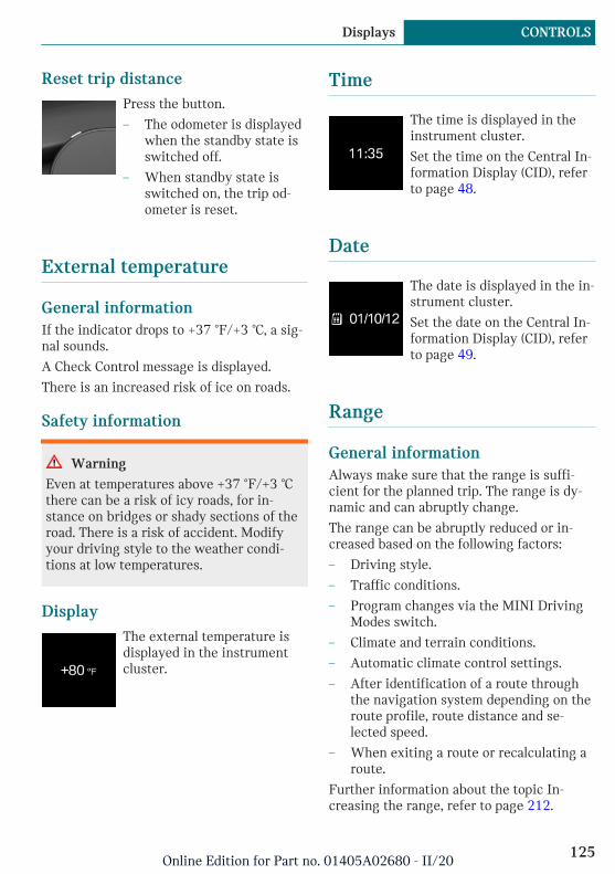
Reset trip distancePress the button.
– The odometer is displayedwhen the standby state isswitched off.
– When standby state isswitched on, the trip od-ometer is reset.
External temperature
General informationIf the indicator drops to +37 ℉/+3 ℃, a sig-nal sounds.
A Check Control message is displayed.
There is an increased risk of ice on roads.
Safety information
Warning
Even at temperatures above +37 ℉/+3 ℃there can be a risk of icy roads, for in-stance on bridges or shady sections of theroad. There is a risk of accident. Modifyyour driving style to the weather condi-tions at low temperatures.
DisplayThe external temperature isdisplayed in the instrumentcluster.
Time
The time is displayed in theinstrument cluster.
Set the time on the Central In-formation Display (CID), referto page 48.
Date
The date is displayed in the in-strument cluster.
Set the date on the Central In-formation Display (CID), referto page 49.
Range
General informationAlways make sure that the range is suffi-cient for the planned trip. The range is dy-namic and can abruptly change.
The range can be abruptly reduced or in-creased based on the following factors:
– Driving style.
– Traffic conditions.
– Program changes via the MINI DrivingModes switch.
– Climate and terrain conditions.
– Automatic climate control settings.
– After identification of a route throughthe navigation system depending on theroute profile, route distance and se-lected speed.
– When exiting a route or recalculating aroute.
Further information about the topic In-creasing the range, refer to page 212.
Seite 125
Displays CONTROLS
125Online Edition for Part no. 01405A02680 - II/20
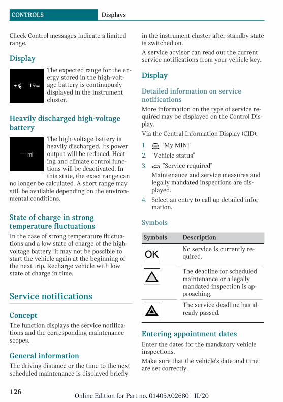
Check Control messages indicate a limitedrange.
DisplayThe expected range for the en-ergy stored in the high-volt-age battery is continuouslydisplayed in the instrumentcluster.
Heavily discharged high-voltagebattery
The high-voltage battery isheavily discharged. Its poweroutput will be reduced. Heat-ing and climate control func-tions will be deactivated. Inthis state, the exact range can
no longer be calculated. A short range maystill be available depending on the environ-mental conditions.
State of charge in strongtemperature fluctuationsIn the case of strong temperature fluctua-tions and a low state of charge of the high-voltage battery, it may not be possible tostart the vehicle again at the beginning ofthe next trip. Recharge vehicle with lowstate of charge in time.
Service notifications
ConceptThe function displays the service notifica-tions and the corresponding maintenancescopes.
General informationThe driving distance or the time to the nextscheduled maintenance is displayed briefly
in the instrument cluster after standby stateis switched on.
A service advisor can read out the currentservice notifications from your vehicle key.
Display
Detailed information on servicenotificationsMore information on the type of service re-quired may be displayed on the Control Dis-play.
Via the Central Information Display (CID):
1. "My MINI"
2. "Vehicle status"
3. "Service required"
Maintenance and service measures andlegally mandated inspections are dis-played.
4. Select an entry to call up detailed infor-mation.
Symbols
Symbols Description
No service is currently re-quired.
The deadline for scheduledmaintenance or a legallymandated inspection is ap-proaching.
The service deadline has al-ready passed.
Entering appointment datesEnter the dates for the mandatory vehicleinspections.
Make sure that the vehicle's date and timeare set correctly.
Seite 126
CONTROLS Displays
126Online Edition for Part no. 01405A02680 - II/20

Via the Central Information Display (CID):
1. "My MINI"
2. "Vehicle status"
3. "Service required"
4. "Vehicle inspection"
5. "Date:"
6. Select the desired setting.
Automatic Service RequestData regarding the service status or legallymandated vehicle inspections is automati-cally transmitted to your dealer’s servicecenter before your vehicle is due for serv-ice.
You can check when your dealer’s servicecenter was notified.
Via the Central Information Display (CID):
1. "My MINI"
2. "Vehicle status"
3. Move the Controller to the left.
4. "Teleservice Call"
Speed Limit Info
Speed Limit Info
ConceptSpeed Limit Info shows the current maxi-mum permitted speed in the instrumentcluster.
General informationThe camera at the base of the interior mir-ror detects traffic signs at the edge of theroad as well as overhead sign posts. Trafficsigns with extra symbols for wet road con-ditions, etc., are also detected and comparedwith the vehicle's onboard data, such as
from the rain sensor, and will be displayeddepending on the situation.
With the navigation system, the systemtakes into account the information stored inthe navigation data and also displays speedlimits present on routes without signs.
Safety information
Warning
The system cannot serve as a substitutefor the driver’s personal judgment in as-sessing visibility and traffic situation.There is a risk of accident. Adjust drivingstyle to traffic conditions. Watch trafficclosely and actively intervene where ap-propriate.
Overview
Camera
The camera is installed near the interiormirror.
Keep the windshield in front of the interiormirror clean and clear.
DisplaySpeed Limit Info is displayed in the instru-ment cluster.
Seite 127
Displays CONTROLS
127Online Edition for Part no. 01405A02680 - II/20

Speed Limit Info
The last speed limit detected.
With navigation system:Speed Limit Info is not availa-ble.
Speed Limit Info can also be displayed inthe Head-up Display.
System limitsThe system may not be fully functional andmay provide incorrect information in thefollowing situations:
– In heavy fog, wet conditions, or snow-fall.
– When traffic signs are fully or partiallyconcealed by objects, stickers or paint.
– When driving very close to the vehiclein front of you.
– When driving toward bright lights orstrong reflections.
– When the windshield in front of the in-terior mirror is fogged over, dirty or cov-ered by a sticker, etc.
– In the event of incorrect detection bythe camera.
– If the speed limits stored in the naviga-tion system are incorrect.
– In areas not covered by the navigationsystem.
– When roads differ from the navigation,such as due to changes in road routing.
– When passing buses or trucks with aspeed sticker.
– If the traffic signs are non-conforming.
– When traffic signs that are valid for aparallel road are detected.
– During calibration of the camera imme-diately after vehicle delivery.
Selection lists
General informationDepending on the vehicle equipment, thebuttons on the steering wheel and the dis-play in the instrument cluster can be usedto display or use the following:
– Current audio source.
– Phone redial.
– Turn on voice activation system.
Activating a list and adjusting thesetting
Button on thesteering wheel
Function
Move selection up.
Move selectiondown.
Confirm the selec-tion.
Display
Seite 128
CONTROLS Displays
128Online Edition for Part no. 01405A02680 - II/20
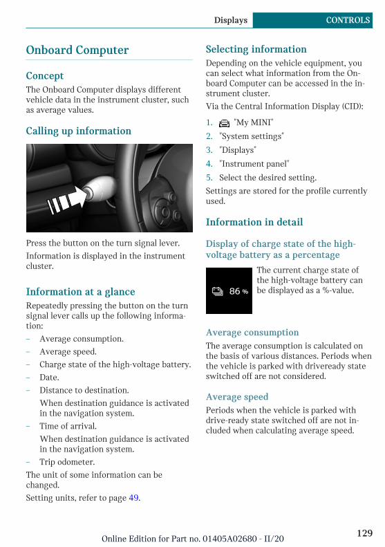
Onboard Computer
ConceptThe Onboard Computer displays differentvehicle data in the instrument cluster, suchas average values.
Calling up information
Press the button on the turn signal lever.
Information is displayed in the instrumentcluster.
Information at a glanceRepeatedly pressing the button on the turnsignal lever calls up the following informa-tion:
– Average consumption.
– Average speed.
– Charge state of the high-voltage battery.
– Date.
– Distance to destination.
When destination guidance is activatedin the navigation system.
– Time of arrival.
When destination guidance is activatedin the navigation system.
– Trip odometer.
The unit of some information can bechanged.
Setting units, refer to page 49.
Selecting informationDepending on the vehicle equipment, youcan select what information from the On-board Computer can be accessed in the in-strument cluster.
Via the Central Information Display (CID):
1. "My MINI"
2. "System settings"
3. "Displays"
4. "Instrument panel"
5. Select the desired setting.
Settings are stored for the profile currentlyused.
Information in detail
Display of charge state of the high-voltage battery as a percentage
The current charge state ofthe high-voltage battery canbe displayed as a %-value.
Average consumptionThe average consumption is calculated onthe basis of various distances. Periods whenthe vehicle is parked with driveready stateswitched off are not considered.
Average speedPeriods when the vehicle is parked withdrive-ready state switched off are not in-cluded when calculating average speed.
Seite 129
Displays CONTROLS
129Online Edition for Part no. 01405A02680 - II/20

Resetting average values
Press and hold the button on the turn signallever.
Distance to destinationDepending on the vehicle equipment, thedistance remaining to the destination is dis-played if a destination is entered in the nav-igation system before the trip is started.
The distance to the destination is adoptedautomatically.
Time of arrivalDepending on the vehicle equipment, theestimated time of arrival is displayed if adestination is entered in the navigation sys-tem before the trip is started.
The time must be correctly set.
Onboard Computer on the ControlDisplay
ConceptThe Onboard Computer displays differentvehicle data on the Control Display, such asaverage values.
General informationTwo types of Onboard Computers are availa-ble on the Control Display:
– "Onboard info": average values, such asthe consumption, are displayed. The val-ues can be reset individually.
– "Trip computer": the values deliver anoverview of a specific route and can bereset as often as necessary.
Calling up the Onboard Computer ortrip computerVia the Central Information Display (CID):
1. "My MINI"
2. "Driving information"
3. "Onboard info" or "Trip computer"
Resetting the Onboard ComputerVia the Central Information Display (CID):
1. "My MINI"
2. "Driving information"
3. "Onboard info"
4. "Consumption" or "Speed"
5. "OK"
Resetting the trip computerVia the Central Information Display (CID):
1. "My MINI"
2. "Driving information"
3. "Trip computer"
4. Move the Controller to the left, ifneeded.
– "Reset": all values are reset.
– "Automatic reset": all values arereset approx. 4 hours after the vehi-cle has come to a standstill.
5. If necessary, "OK"
Speed warning
ConceptA speed limit can be set that when reachedwill cause a warning to be issued.
Seite 130
CONTROLS Displays
130Online Edition for Part no. 01405A02680 - II/20
General informationThe warning is repeated if the vehicle speedexceeds the set speed limit again, after ithas dropped below it by 3 mph/5 km/h.
AdjustingVia the Central Information Display (CID):
1. "My MINI"
2. "Vehicle settings"
3. "Speed warning"
4. "Warning at:"
5. Turn the Controller until the desiredspeed is displayed.
6. Press the Controller.
Activating/deactivatingVia the Central Information Display (CID):
1. "My MINI"
2. "Vehicle settings"
3. "Speed warning"
4. "Speed warning"
Setting your current speed as thespeed warningVia the Central Information Display (CID):
1. "My MINI"
2. "Vehicle settings"
3. "Speed warning"
4. "Select current speed"
LED ring on the central in-strument cluster
ConceptThe LED ring displays light animations torepresent specific functions.
Basic displaysBasic functions, such as the state of chargeof the high-voltage battery, can be set to bedisplayed continually if so desired.
Event displaysFunctions that are only displayed tempora-rily, for instance the volume or temperaturesettings, can be set as event displays.
Several vehicle assistance functions canalso be displayed on the LED ring. This dis-play corresponds with the displays of thefunction in the respective display.
Switching on/off LED ringVia the Central Information Display (CID):
1. "My MINI"
2. "System settings"
3. "Displays"
4. "Center Instrument"
5. "Center Instrument"
Adjusting the LED ringVia the Central Information Display (CID):
1. "My MINI"
2. "System settings"
3. "Displays"
4. "Center Instrument"
5. "Basic display" or "Event display"
6. Select the desired setting.
Setting the brightnessThe brightness can be adjusted when nightlighting is active in the instrument cluster.
Via the Central Information Display (CID):
1. "My MINI"
2. "System settings"
Seite 131
Displays CONTROLS
131Online Edition for Part no. 01405A02680 - II/20
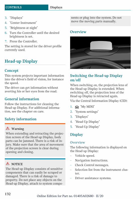
3. "Displays"
4. "Center Instrument"
5. "Brightness at night"
6. Turn the Controller until the desiredbrightness is set.
7. Press the Controller.
The setting is stored for the driver profilecurrently used.
Head-up Display
ConceptThis system projects important informationinto the driver's field of vision, for instancethe speed.
The driver can get information withoutaverting his or her eyes from the road.
General informationFollow the instructions for cleaning theHead-up Display. For additional informa-tion, see the chapter on care.
Safety information
Warning
When extending and retracting the projec-tion screen of the Head-up Display, bodyparts can be jammed. There is a risk of in-jury. Make sure that the area of movementof the projection screen is clear duringopening and closing.
NOTICE
The Head-up Display consists of sensitivecomponents that can easily be scraped ordamaged. There is a risk of damage toproperty. Do not place any objects on theHead-up Display, attach to system compo-
nents or plug into the system. Do notmove the moving parts manually.
Overview
Switching the Head-up Displayon/offWhen switching on, the projection lens ofthe Head-up Display is extended. Whenswitching off, the projection lens of theHead-up Display is retracted again.
Via the Central Information Display (CID):
1. "My MINI"
2. "System settings"
3. "Displays"
4. "Head-Up Display"
5. "Head-Up Display"
Display
OverviewThe following information is displayed onthe Head-up Display:
– Vehicle speed.
– Navigation instructions.
– Check Control messages.
– Selection list from the instrument clus-ter.
– Driver assistance systems.
Seite 132
CONTROLS Displays
132Online Edition for Part no. 01405A02680 - II/20

Some of this information is only displayedbriefly as needed.
Selecting displays in the Head-upDisplayVia the Central Information Display (CID):
1. "My MINI"
2. "System settings"
3. "Displays"
4. "Head-Up Display"
5. "Displayed information"
6. Select the desired displays in the Head-up Display.
Settings are stored for the driver profilecurrently used.
Setting the brightnessThe brightness is automatically adjusted tothe ambient brightness.
The basic setting can be adjusted manually.
Via the Central Information Display (CID):
1. "My MINI"
2. "System settings"
3. "Displays"
4. "Head-Up Display"
5. "Brightness"
6. Turn the Controller until the desiredbrightness is set.
7. Press the Controller.
When the low beams are switched on, thebrightness of the Head-up Display can beadditionally influenced using the instru-ment lighting, refer to page 139.
The setting is stored for the driver profilecurrently used.
Adjusting the heightVia the Central Information Display (CID):
1. "My MINI"
2. "System settings"
3. "Displays"
4. "Head-Up Display"
5. "Height"
6. Turn the Controller until the desiredheight is reached.
7. Press the Controller.
The setting is stored for the driver profilecurrently used.
Setting the rotationThe screen of the Head-up Display can berotated around its own axis.
Via the Central Information Display (CID):
1. "My MINI"
2. "System settings"
3. "Displays"
4. "Head-Up Display"
5. "Rotation"
6. Turn the Controller until the desired set-ting is selected.
7. Press the Controller.
The setting is stored for the driver profilecurrently used.
Display visibilityThe visibility of the displays in the Head-upDisplay is influenced by the following fac-tors:
– Certain sitting positions.
– Objects on the cover of the Head-up Dis-play.
– Sunglasses with certain polarization fil-ters.
Seite 133
Displays CONTROLS
133Online Edition for Part no. 01405A02680 - II/20
– Wet roads.
– Unfavorable light conditions.
Vehicle status
General informationThe status can be displayed and actions per-formed for several systems.
Opening the vehicle statusVia the Central Information Display (CID):
1. "My MINI"
2. "Vehicle status"
Information at a glance
Symbols Description
"Flat Tire Monitor": status ofthe run-flat tires, refer topage 150.
"Tire Pressure Monitor": sta-tus of the Tire PressureMonitor TPM, refer topage 145.
"Check Control": Check Con-trol messages are stored inthe background and can bedisplayed on the ControlDisplay. Displaying storedCheck Control messages, re-fer to page 124.
"Service required": display-ing service notifications, re-fer to page 126.
"Teleservice Call": Serv-ice Request.
Seite 134
CONTROLS Displays
134Online Edition for Part no. 01405A02680 - II/20

Lights
Vehicle features and options
This chapter describes all standard, country-specific and optional features offered withthe series. It also describes features andfunctions that are not necessarily availablein your vehicle, e.g., due to the selected op-tions or country versions. This also appliesto safety-related functions and systems.When using these functions and systems,the applicable laws and regulations must beobserved.
Overview
Switches in the vehicle
The light switch element is located next tothe steering wheel.
Symbol Function
Front fog lights.
Automatic headlight control.
Cornering light.
Lights off.
Daytime running lights.
Symbol Function
Parking lights.
Low beams.
Instrument lighting.
Parking lights, low beams androadside parking lights
General informationPosition of switch: , ,
If the driver's door is opened when standbystate is switched off, the exterior lighting isautomatically switched off.
Parking lightsPosition of switch:
The vehicle is illuminated on all sides.
Do not use the parking lights for extendedperiods; otherwise, they might drain thebattery and it would then be impossible toswitch on drive-ready state.
When parking, switch on the one-sidedroadside parking light, refer to page 136.
Low beamsPosition of switch:
The low beams illuminate when standbystate is switched on.
Seite 135
Lights CONTROLS
135Online Edition for Part no. 01405A02680 - II/20

Canada: roadside parking light
ConceptThe vehicle can be illuminated on one side.
Switching on
With radio-ready state switched off, pressthe lever either up or down past the resist-ance point for approx. 2 seconds.
Switching offBriefly press the lever to the resistancepoint in the opposite direction.
Welcome lights and pathwaylighting
Welcome lights
General informationDepending on the vehicle equipment andthe ambient brightness, individual lightfunctions may be switched on briefly whenthe vehicle is unlocked.
Activating/deactivatingPosition of switch: ,
Via the Central Information Display (CID):
1. "My MINI"
2. "Vehicle settings"
3. "Lighting"
4. "Exterior lighting"
5. "Welcome lights"
The setting is stored for the driver profilecurrently used.
Pathway lighting
General informationThe low beams stay lit for a short while ifthe headlight flasher is switched on afterthe vehicle's radio-ready state is switchedoff.
Setting the durationVia the Central Information Display (CID):
1. "My MINI"
2. "Vehicle settings"
3. "Lighting"
4. "Exterior lighting"
5. "Pathway lighting"
6. Set length of time.
The setting is stored for the driver profilecurrently used.
Automatic headlight control
ConceptThe low beams are switched on and off au-tomatically depending on the ambientbrightness, for example in tunnels, in twi-light or if there is precipitation.
General informationA blue sky with the sun low on the horizoncan cause the lights to be switched on.
ActivatingPosition of switch:
Seite 136
CONTROLS Lights
136Online Edition for Part no. 01405A02680 - II/20
The indicator light in the instrument clusteris illuminated when the low beams areswitched on.
System limitsThe automatic headlight control cannotserve as a substitute for your personal judg-ment of lighting conditions.
For example, the sensors are unable to de-tect fog or hazy weather. In these situa-tions, switch the lights on manually.
Daytime running lights
General informationPosition of switch: , ,
The daytime running lights light up whenstandby state is switched on. After standbystate is switched off, the parking lights lightup in position .
Activating/deactivatingIn some countries, daytime running lightsare mandatory, so it may not be possible todeactivate the daytime running lights.
Via the Central Information Display (CID):
1. "My MINI"
2. "Vehicle settings"
3. "Lighting"
4. "Exterior lighting"
5. Select the desired setting.
Settings are stored for the currently usedvehicle key.
Cornering light
General informationPosition of switch:
In tight curves, for instance on mountain-ous roads or when turning, an additional,cornering light is switched on that lights upthe inside of the curve when the vehicle ismoving below a certain speed.
The cornering light is automaticallyswitched on depending on the steering an-gle or, where applicable, the use of turn sig-nals.
When driving in reverse, the corneringlights may be automatically switched on re-gardless of the steering angle.
Adaptive headlight range con-trol
The adaptive headlight range control fea-ture balances out acceleration and brakingprocesses as well as the vehicle load condi-tions in order to avoid dazzling oncomingtraffic. Illumination of the road is optimized.
High-beam Assistant
ConceptThe high-beam Assistant detects other traf-fic participants early on and automaticallyswitches the high beams on or off depend-ing on the traffic situation.
General informationThe high-beam Assistant ensures that thehigh beams are switched on, whenever thetraffic situation allows. In the low speedrange, the high beams are not switched onby the system.
The system responds to light from oncom-ing traffic and traffic driving ahead of you,and to ambient lighting, for instance intowns and cities.
Seite 137
Lights CONTROLS
137Online Edition for Part no. 01405A02680 - II/20
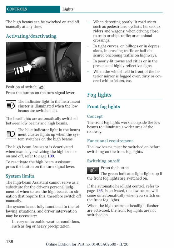
The high beams can be switched on and offmanually at any time.
Activating/deactivating
Position of switch:
Press the button on the turn signal lever.
The indicator light in the instrumentcluster is illuminated when the lowbeams are switched on.
The headlights are automatically switchedbetween low beams and high beams.
The blue indicator light in the instru-ment cluster lights up when the sys-tem switches on the high beams.
The high-beam Assistant is deactivatedwhen manually switching the high beamson and off, refer to page 109.
To reactivate the high-beam Assistant,press the button on the turn signal lever.
System limitsThe high-beam Assistant cannot serve as asubstitute for the driver's personal judg-ment of when to use the high beams. In sit-uation that require this, therefore switch offmanually.
The system is not fully functional in the fol-lowing situations, and driver interventionmay be necessary:
– In very unfavorable weather conditions,such as fog or heavy precipitation.
– When detecting poorly-lit road userssuch as pedestrians, cyclists, horsebackriders and wagons; when driving closeto train or ship traffic; or at animalcrossings.
– In tight curves, on hilltops or in depres-sions, in crossing traffic or half-ob-scured oncoming traffic on highways.
– In poorly-lit towns and cities or in thepresence of highly reflective signs.
– When the windshield in front of the in-terior mirror is fogged over, dirty or cov-ered with stickers, etc.
Fog lights
Front fog lights
ConceptThe front fog lights work alongside the lowbeams to illuminate a wider area of theroadway.
Functional requirementThe low beams must be switched on beforeswitching on the front fog lights.
Switching on/off
Press the button.
The green indicator light lights up ifthe front fog lights are switched on.
If the automatic headlight control, refer topage 136, is activated, the low beams willcome on automatically when you switch onthe front fog lights.
When the high beams or headlight flasherare activated, the front fog lights are notswitched on.
Seite 138
CONTROLS Lights
138Online Edition for Part no. 01405A02680 - II/20

Instrument lighting
Functional requirementThe parking lights or low beams must beswitched on to adjust the brightness.
AdjustingAdjust the brightness with thethumbwheel.
Interior lights
General informationDepending on the equipment, the interiorlights, footwell lights, entry lights, and cour-tesy lights are controlled automatically.
The thumbwheel for the instrument lightingcontrols brightness of some of these fea-tures.
Overview
1 Interior lights
2 Reading lights
3 Ambient light
Switching the interior lights on/offPress the button.
To switch off permanently: press the buttonand hold for approx. 3 seconds.
Switching the reading lights on andoff manually
Press the button.
The reading lights are located in the frontnext to the interior light.
Ambient light
General informationDepending on the equipment version, light-ing can be adjusted for some lights in thecar's interior.
Activating/deactivatingVia the Central Information Display (CID):
1. "My MINI"
2. "Vehicle settings"
3. "Lighting"
4. "Interior lighting"
5. "Ambient lighting"
6. Select the desired setting.
Settings are stored for the profile currentlyused.
Changing color
Push the switch forward or back:manual color change.
Press the switch forward or back-ward and hold for approx. 3 seconds,until the ambient light illuminates
Seite 139
Lights CONTROLS
139Online Edition for Part no. 01405A02680 - II/20

several times: automatic color change. Pushthe switch again to end color changes.
Setting the brightnessDepending on the equipment, the bright-ness of the ambient light can be adjustedvia the thumbwheel for the instrumentlighting or on the Control Display.
Via the Central Information Display (CID):
1. "My MINI"
2. "Vehicle settings"
3. "Lighting"
4. "Interior lighting"
5. "Brightness"
6. Adjust the brightness.
Seite 140
CONTROLS Lights
140Online Edition for Part no. 01405A02680 - II/20

Safety
Vehicle features and options
This chapter describes all standard, country-specific and optional features offered withthe series. It also describes features andfunctions that are not necessarily available
in your vehicle, e.g., due to the selected op-tions or country versions. This also appliesto safety-related functions and systems.When using these functions and systems,the applicable laws and regulations must beobserved.
Airbags
1 Front airbag, driver
2 Front airbag, front passenger
3 Head airbag
4 Side airbag
5 Knee airbag
Front airbagsFront airbags help protect the driver andthe front passenger by responding to frontalimpacts in which safety belts alone wouldnot provide adequate protection.
Side airbagIn the event of a side impact, the side air-bag protects the side of the body in thechest and lap area.
Seite 141
Safety CONTROLS
141Online Edition for Part no. 01405A02680 - II/20
Head airbagIn the event of a side impact, the head air-bag protects the head.
Ejection MitigationThe head airbag system is designed as anejection mitigation countermeasure to re-duce the likelihood of ejections of vehicleoccupants through side windows duringrollovers or side impact events.
Knee airbagThe knee airbag protects the legs in theevent of a frontal impact.
Protective effectAirbags are not triggered in every impactsituation, for instance in less severe acci-dents or rear-end collisions.
Information on optimum effect of theairbags
Warning
If the seat position is incorrect or the de-ployment area of the airbags is impaired,the airbag system cannot provide protec-tion as intended and may cause additionalinjuries due to triggering. There is a riskof injuries or danger to life. Follow the in-formation on achieving the optimum pro-tective effect of the airbag system.
– Keep a distance from the airbags.
– Always grasp the steering wheel on thesteering wheel rim. Hold your hands atthe 3 o'clock and 9 o'clock positions, tokeep the risk of injury to your hands orarms as low as possible when the airbagis triggered.
– Make sure that the front passenger issitting correctly, i.e., keeps his or her
feet and legs in the floor area and doesnot support them on the dashboard.
– Make sure that occupants keep theirheads away from the side airbag.
– There should be no additional persons,animals or objects between an airbagand a person.
– Dashboard and windshield on the frontpassenger side must stay clear - do notattach adhesive labels or coverings anddo not attach brackets or cables, for in-stance for GPS devices or mobilephones.
– Do not apply adhesive materials to theairbag cover panels, do not cover themor modify them in any way.
– Do not use the cover of the front airbagon the front passenger side as a storagearea.
– Do not attach slip covers, seat cushionsor other objects to the front passengerseat that are not specifically suited forseats with integrated side airbags.
– Do not place seat cushions or other ob-jects on the front seats that are not spe-cifically suited for seats with integratedside airbags.
– Do not hang pieces of clothing, such asjackets, over the backrests.
– Never modify either the individual com-ponents or the wiring in the airbag sys-tem. This also applies to steering wheelcovers, the dashboard, and the seats.
– Do not remove the airbag system.
Even when you follow all instructions veryclosely, injury from contact with the airbagscannot be fully ruled out in certain situa-tions.
The ignition and inflation noise may lead toshort-term and, in most cases, temporaryhearing impairment in sensitive occupants.
Vehicle modifications for a person with dis-abilities may affect the air bag system; con-
Seite 142
CONTROLS Safety
142Online Edition for Part no. 01405A02680 - II/20

tact MINI Customer Relations for further in-formation.
Warnings and information on the airbagsare also found on the sun visors.
Functional readiness of the airbagsystem
Safety information
Warning
Individual components can be hot aftertriggering of the airbag system. There is arisk of injury. Do not touch individualcomponents.
Warning
Improperly executed work can lead to fail-ure, malfunction or unintentional trigger-ing of the airbag system. In the case of amalfunction, the airbag system might nottrigger as intended despite the accidentseverity. There is a risk of injuries or dan-ger to life. Have the airbag systemchecked, repaired, dismantled and scrap-ped by a dealer’s service center or anotherqualified service center or repair shop.
Correct function
With the standby state switched on,the warning light in the instrumentcluster lights up briefly, indicating
the airbag system and belt tensioner arefunctional.
Airbag system malfunctioning– Warning light does not come on when
standby state is switched on.
– The warning light lights up continu-ously.
Automatic deactivation of thefront-seat passenger airbags
ConceptThe system reads if the front passenger seatis occupied by measuring the human body'sresistance.
Front, knee, and side airbag on the frontpassenger's side are activated or deacti-vated.
General informationBefore transporting a child on the front pas-senger seat, refer to the safety informationand instructions for children on the frontpassenger seat, see Children.
Safety information
Warning
To ensure the front-seat passenger airbagfunction, the system must be able to de-tect whether a person is sitting in thefront passenger seat. The entire seat cush-ion area must be used for this purpose.There is a risk of injuries or danger to life.Make sure that the front passenger keepshis or her feet in the floor area.
Malfunction of the automaticdeactivation systemWhen transporting older children andadults, the front-seat passenger airbags maybe deactivated in certain sitting positions.In this case, the indicator light for the front-seat passenger airbags lights up.
In this case, change the sitting position sothat the front-seat passenger airbags are ac-tivated and the indicator light goes out.
If it is not possible to activate the airbags,have the person sit in the rear.
Seite 143
Safety CONTROLS
143Online Edition for Part no. 01405A02680 - II/20
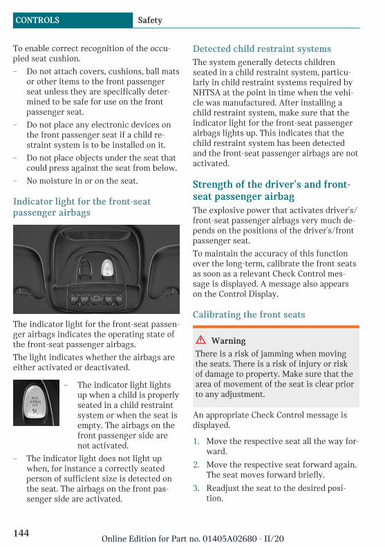
To enable correct recognition of the occu-pied seat cushion.
– Do not attach covers, cushions, ball matsor other items to the front passengerseat unless they are specifically deter-mined to be safe for use on the frontpassenger seat.
– Do not place any electronic devices onthe front passenger seat if a child re-straint system is to be installed on it.
– Do not place objects under the seat thatcould press against the seat from below.
– No moisture in or on the seat.
Indicator light for the front-seatpassenger airbags
The indicator light for the front-seat passen-ger airbags indicates the operating state ofthe front-seat passenger airbags.
The light indicates whether the airbags areeither activated or deactivated.
– The indicator light lightsup when a child is properlyseated in a child restraintsystem or when the seat isempty. The airbags on thefront passenger side arenot activated.
– The indicator light does not light upwhen, for instance a correctly seatedperson of sufficient size is detected onthe seat. The airbags on the front pas-senger side are activated.
Detected child restraint systemsThe system generally detects childrenseated in a child restraint system, particu-larly in child restraint systems required byNHTSA at the point in time when the vehi-cle was manufactured. After installing achild restraint system, make sure that theindicator light for the front-seat passengerairbags lights up. This indicates that thechild restraint system has been detectedand the front-seat passenger airbags are notactivated.
Strength of the driver's and front-seat passenger airbagThe explosive power that activates driver's/front-seat passenger airbags very much de-pends on the positions of the driver's/frontpassenger seat.
To maintain the accuracy of this functionover the long-term, calibrate the front seatsas soon as a relevant Check Control mes-sage is displayed. A message also appearson the Control Display.
Calibrating the front seats
Warning
There is a risk of jamming when movingthe seats. There is a risk of injury or riskof damage to property. Make sure that thearea of movement of the seat is clear priorto any adjustment.
An appropriate Check Control message isdisplayed.
1. Move the respective seat all the way for-ward.
2. Move the respective seat forward again.The seat moves forward briefly.
3. Readjust the seat to the desired posi-tion.
Seite 144
CONTROLS Safety
144Online Edition for Part no. 01405A02680 - II/20

The calibration procedure is completedwhen the Check Control message disap-pears.
If the message continues to be displayed,repeat the calibration.
If the message does not disappear after a re-peat calibration, have the system checkedas soon as possible.
Tire Pressure Monitor TPM
ConceptThe system monitors tire inflation pressurein the four mounted tires. The system warnsyou if there is a significant loss of pressurein one or more tires.
General informationSensors in the tire valves measure the tireinflation pressure and, depending on themodel, the tire temperature.
Further information and instructions on us-ing the system can also be found under Tireinflation pressure, refer to page 227.
Functional requirementsThe following conditions must be met forthe system; otherwise, reliable flagging of aloss of tire inflation pressure is not assured:
– After a tire or wheel replacement, a re-set was performed with the correct tireinflation pressure.
– After the tire inflation pressure was ad-justed to a new value, a reset was per-formed.
– Wheels with TPM wheel electronics.
Status display
Current statusThe system status can be displayed on theControl Display, e.g., whether or not the sys-tem is active.
Via the Central Information Display (CID):
1. "My MINI"
2. "Vehicle status"
3. "Tire Pressure Monitor"
The current status is displayed.
Tire conditions
General informationTire and system status are indicated by thecolor of the wheels and a SMS text messageon the Control Display.
All wheels greenSystem is active and will issue a warning re-lated to the tire inflation pressures storedduring the last reset.
One to four yellow wheelsA flat tire or major drop in the tire inflationpressure has occurred in the indicated tires.
Gray wheelsIt may not be possible to identify tire infla-tion pressure losses.
Possible causes:
– Malfunction.
– The system is being reset.
Additional informationThe status control display additionallyshows the current tire inflation pressures.The values shown are instantaneous meas-urements and may vary depending on driv-ing style or weather conditions.
Seite 145
Safety CONTROLS
145Online Edition for Part no. 01405A02680 - II/20
Resetting the systemVia the Central Information Display (CID):
1. "My MINI"
2. "Vehicle status"
3. "Tire Pressure Monitor"
4. Switch on drive-ready state and do notdrive off.
5. Reset tire inflation pressure: "Performreset".
6. Drive away.
The wheels are displayed in gray and thefollowing is displayed "Resetting TirePressure Monitor…".
After a travel time of several minutes, theset tire inflation pressures are accepted asreference values. The resetting process iscompleted automatically while driving.
After successful completion of the reset, thetires appear in green on the Control Displayand "Tire Pressure Monitor active. See labelfor recommended pressures." is displayed.
You may interrupt this trip at any time.When you continue the reset resumes auto-matically.
Messages
General informationA low tire inflation pressure may cause theDSC Dynamic Stability Control to beswitched on.
Safety information
Warning
A damaged regular tire with low or miss-ing tire inflation pressure impacts han-dling, such as steering and braking re-sponse. Run-flat tires can maintain limitedstability. There is a risk of accident. Do notcontinue driving if the vehicle is equipped
with normal tires. Follow the informationon run-flat tires and continued drivingwith these tires.
If a tire inflation pressure check isrequired
Message
A symbol with a Check Control message ap-pears on the Control Display.
Symbol Possible cause
The system has detected awheel change, but no reset wasdone.
No reset was performed for thesystem. The system issues awarning based on the tire infla-tion pressures stored during thelast reset.
Inflation was not carried out ac-cording to specifications.
The tire inflation pressure hasfallen below the level of the lastreset.
Measure
1. Check the tire pressure and correct asneeded.
2. Reset the system.
If the tire inflation pressure is too low
Message
A yellow warning light is illuminatedin the instrument cluster.
In addition, a symbol with a Check Controlmessage appears on the Control Display.
Seite 146
CONTROLS Safety
146Online Edition for Part no. 01405A02680 - II/20
Symbol Possible cause
There is a tire inflation pressureloss.
No reset was performed for thesystem. The system issues awarning based on the tire infla-tion pressures stored during thelast reset.
Measure
1. Reduce your speed and drive moder-ately. Do not exceed a speed of80 mph/130 km/h.
2. At the next opportunity, for instance gasstation, check and correct the tire infla-tion pressure in all four tires, if neces-sary.
3. Reset the system.
If there is a significant loss of tireinflation pressure
Message
A yellow warning light is illuminatedin the instrument cluster.
In addition, a symbol with the affected tireappears in a Check Control message on theControl Display.
Symbol Possible cause
There is a flat tire or a majorloss in tire inflation pressure.
No reset was performed for thesystem. The system issues awarning based on the tire infla-tion pressures stored during thelast reset.
Measure
1. Reduce your speed and stop cautiously.Avoid sudden braking and steering ma-neuvers.
2. Check whether the vehicle is fitted withnormal tires or run-flat tires.
Run-flat tires, refer to page 233, are la-beled with a circular symbol containingthe letters RSC marked on the tire'ssidewall.
Actions in the event of a flat tire
Normal tires1. Identify the damaged tire.
To do this, check the tire inflation pres-sure in all four tires, for instance usingthe tire pressure gage of a flat tire kit.
If the tire inflation pressure in all fourtires is correct, the Tire Pressure Moni-tor may not have been reset. In thiscase, perform the reset.
If the tire inflation pressure in all fourtires is correct, the Flat Tire Monitormay not have been initialized. In thiscase, initialize the system.
If identification of flat tire damage isnot possible, please contact a dealer’sservice center or another qualified serv-ice center or repair shop.
2. Repair the flat tire, e.g., with a flat tirekit or by changing the wheel.
Use of sealant, for instance from the flat tirekit, may damage the TPM wheel electronics.In this case, have the electronics checkedand replaced at the next opportunity.
Seite 147
Safety CONTROLS
147Online Edition for Part no. 01405A02680 - II/20
Run-flat tires
Safety information
Warning
The vehicle handles differently when arun-flat tire has insufficient or no tirepressure; for instance, reduced lane stabil-ity when braking, braking distances arelonger and the self-steering properties willchange. There is a risk of accident. Drivemoderately and do not exceed a speed of50 mph/80 km/h.
Maximum speed
You may continue driving with a damagedtire at speeds up to 50 mph/80 km/h.
Continued driving with a flat tire
If continuing to drive with a damaged tire:
1. Avoid sudden braking and steering ma-neuvers.
2. Do not exceed a speed of50 mph/80 km/h.
3. Check the tire inflation pressure in allfour tires at the next opportunity.
If the tire inflation pressure in all fourtires is correct, the Tire Pressure Moni-tor may not have been reset. In thiscase, perform the reset.
Possible driving range with adepressurized tire
The distance for which it may be possible todrive safely varies depending on how thevehicle is loaded and used, e.g., speed, roadconditions, external temperature. The driv-ing range may be less but may also be moreif an economical driving style is used.
If the vehicle is loaded with an averageweight and used under favorable conditions,
the distance for which it may be safe todrive may be up to 50 miles/80 km.
Vehicle handling with damaged tires
Vehicles driven with a damaged tire willhandle differently, potentially leading toconditions such as the following:
– Greater likelihood of swerving offcourse.
– Longer braking distances.
– Changed self-steering properties.
Modify your driving style. Avoid abruptsteering maneuvers or driving over obsta-cles, for instance curbs or potholes.
Final tire failure
Vibrations or loud noises while driving canindicate the final failure of a tire.
Reduce speed and stop; otherwise, pieces ofthe tire could come loose and cause an acci-dent.
Do not continue driving. Contact a dealer’sservice center or another qualified servicecenter or repair shop.
System limits
TemperatureThe tire inflation pressure depends on thetire's temperature.
Driving or exposure to the sun will increasethe tire's temperature, thus increasing thetire inflation pressure.
The tire inflation pressure is reduced whenthe tire temperature falls again.
These circumstances may cause a warningwhen temperatures fall very sharply.
Sudden tire pressure lossThe system cannot indicate sudden serioustire damage caused by external circumstan-ces.
Seite 148
CONTROLS Safety
148Online Edition for Part no. 01405A02680 - II/20

Failure performing a resetThe system does not function properly if areset has not been carried out, for instancea flat tire is reported though tire inflationpressures are correct.
MalfunctionThe yellow warning light flashes andis then illuminated continuously. ACheck Control message is displayed.
It may not be possible to identify tire pres-sure losses.
Examples and recommendations in the fol-lowing situations:
– A wheel without TPM wheel electronicsis mounted: have it checked by a deal-er’s service center or another qualifiedservice center or repair shop as needed.
– Malfunction: have system checked by adealer’s service center or another quali-fied service center or repair shop.
– The system was unable to complete thereset. Perform a system reset again.
– Interference caused by systems or devi-ces with the same radio frequency: afterleaving the area of the interference, thesystem automatically becomes activeagain.
Declaration according to NHTSA/FMVSS 138 Tire Pressure MonitoringSystemEach tire, including the spare (if provided)should be checked monthly when cold andinflated to the inflation pressure recom-mended by the vehicle manufacturer on thevehicle placard or tire inflation pressure la-bel. (If your vehicle has tires of a differentsize than the size indicated on the vehicleplacard or tire inflation pressure label, youshould determine the proper tire inflationpressure for those tires.) As an added safetyfeature, your vehicle has been equipped
with a tire pressure monitoring system(TPMS) that illuminates a low tire pressuretelltale when one or more of your tires issignificantly under-inflated. Accordingly,when the low tire pressure telltale illumi-nates, you should stop and check your tiresas soon as possible, and inflate them to theproper pressure. Driving on a significantlyunder-inflated tire causes the tire to over-heat and can lead to tire failure. Under-infla-tion also reduces fuel efficiency and tiretread life, and may affect the vehicle's han-dling and stopping ability. Please note thatthe TPMS is not a substitute for proper tiremaintenance, and it is the driver's responsi-bility to maintain correct tire pressure, evenif under-inflation has not reached the levelto trigger illumination of the TPMS low tirepressure telltale. Your vehicle has also beenequipped with a TPMS malfunction indica-tor to indicate when the system is not oper-ating properly. The TPMS malfunction indi-cator is combined with the low tire pressuretelltale. When the system detects a mal-function, the telltale will flash for approxi-mately one minute and then remain contin-uously illuminated. This sequence willcontinue upon subsequent vehicle start-upsas long as the malfunction exists. When themalfunction indicator is illuminated, thesystem may not be able to detect or signallow tire pressure as intended. TPMS mal-functions may occur for a variety of rea-sons, including the installation of replace-ment or alternate tires or wheels on thevehicle that prevent the TPMS from func-tioning properly. Always check the TPMSmalfunction telltale after replacing one ormore tires or wheels on your vehicle to en-sure that the replacement or alternate tiresand wheels allow the TPMS to continue tofunction properly.
Seite 149
Safety CONTROLS
149Online Edition for Part no. 01405A02680 - II/20
Flat Tire Monitor FTM
ConceptThe system detects tire inflation pressureloss on the basis of rotation speed differen-ces between the individual wheels whiledriving.
In the event of a tire inflation pressure loss,the diameter and therefore the rotationalspeed of the corresponding wheel changes.The difference will be detected and reportedas a flat tire.
The system does not measure the actual in-flation pressure in the tires.
Functional requirementsThe following conditions must be met forthe system; otherwise, reliable flagging of aloss of tire inflation pressure is not assured:
– After a tire or wheel replacement, an ini-tialization was performed with the cor-rect tire inflation pressure.
– After the tire pressure was adjusted to anew value, an initialization was per-formed.
Status displayThe current status of the flat tire monitorcan be displayed, for instance whether theRPA is active.
Via the Central Information Display (CID):
1. "My MINI"
2. "Vehicle status"
3. "Flat Tire Monitor"
The status is displayed.
Initialization requiredAn initialization must be performed in thefollowing situations:
– After the tire inflation pressure hasbeen adjusted.
– After a tire or wheel replacement.
Performing initializationWhen initializing, the set tire inflationpressures serve as reference values in orderto detect a flat tire. Initialization is startedby confirming the tire inflation pressures.
Do not initialize the system when drivingwith snow chains.
Via the Central Information Display (CID):
1. "My MINI"
2. "Vehicle status"
3. "Flat Tire Monitor"
4. Switch on drive-ready state and do notdrive off.
5. Start the initialization with: "Performreset".
6. Drive away.
The initialization is completed while driv-ing, which can be interrupted at any time.
The initialization automatically continueswhen driving resumes.
Messages
General informationWhen a flat tire is indicated, DSC DynamicStability Control is switched on, if needed.
Safety information
Warning
A damaged regular tire with low or miss-ing tire inflation pressure impacts han-dling, such as steering and braking re-sponse. Run-flat tires can maintain limitedstability. There is a risk of accident. Do notcontinue driving if the vehicle is equippedwith normal tires. Follow the information
Seite 150
CONTROLS Safety
150Online Edition for Part no. 01405A02680 - II/20

on run-flat tires and continued drivingwith these tires.
Indication of a flat tire
A yellow warning light is illuminatedin the instrument cluster.
In addition, a symbol with a Check Controlmessage appears on the Control Display.
Symbol Possible cause
There is a flat tire or a majorloss in tire inflation pressure.
Measure1. Reduce your speed and stop cautiously.
Avoid sudden braking and steering ma-neuvers.
2. Check whether the vehicle is fitted withnormal tires or run-flat tires.
Run-flat tires, refer to page 233, are la-beled with a circular symbol containingthe letters RSC marked on the tire'ssidewall.
Actions in the event of a flat tire
Normal tires1. Identify the damaged tire.
To do this, check the tire inflation pres-sure in all four tires, for instance usingthe tire pressure gage of a flat tire kit.
If the tire inflation pressure in all fourtires is correct, the Tire Pressure Moni-tor may not have been reset. In thiscase, perform the reset.
If the tire inflation pressure in all fourtires is correct, the Flat Tire Monitormay not have been initialized. In thiscase, initialize the system.
If identification of flat tire damage isnot possible, please contact a dealer’sservice center or another qualified serv-ice center or repair shop.
2. Repair the flat tire, e.g., with a flat tirekit or by changing the wheel.
Use of sealant, for instance from the flat tirekit, may damage the TPM wheel electronics.In this case, have the electronics checkedand replaced at the next opportunity.
Run-flat tires
Safety information
Warning
The vehicle handles differently when arun-flat tire has insufficient or no tirepressure; for instance, reduced lane stabil-ity when braking, braking distances arelonger and the self-steering properties willchange. There is a risk of accident. Drivemoderately and do not exceed a speed of50 mph/80 km/h.
Maximum speed
You may continue driving with a damagedtire at speeds up to 50 mph/80 km/h.
Continued driving with a flat tire
If continuing to drive with a damaged tire:
1. Avoid sudden braking and steering ma-neuvers.
2. Do not exceed a speed of50 mph/80 km/h.
3. Check the tire inflation pressure in allfour tires at the next opportunity.
If the tire inflation pressure in all fourtires is correct, the Flat Tire Monitormay not have been initialized. In thiscase, initialize the system.
Seite 151
Safety CONTROLS
151Online Edition for Part no. 01405A02680 - II/20
Possible driving range with adepressurized tire
The distance for which it may be possible todrive safely varies depending on how thevehicle is loaded and used, e.g., speed, roadconditions, external temperature. The driv-ing range may be less but may also be moreif an economical driving style is used.
If the vehicle is loaded with an averageweight and used under favorable conditions,the distance for which it may be safe todrive may be up to 50 miles/80 km.
Vehicle handling with damaged tires
Vehicles driven with a damaged tire willhandle differently, potentially leading toconditions such as the following:
– Greater likelihood of swerving offcourse.
– Longer braking distances.
– Changed self-steering properties.
Modify your driving style. Avoid abruptsteering maneuvers or driving over obsta-cles, for instance curbs or potholes.
Final tire failure
Vibrations or loud noises while driving canindicate the final failure of a tire.
Reduce speed and stop; otherwise, pieces ofthe tire could come loose and cause an acci-dent.
Do not continue driving. Contact a dealer’sservice center or another qualified servicecenter or repair shop.
System limitsThe system could be delayed or malfunctionin the following situations:
– A natural, even tire inflation pressureloss in all four tires will not be recog-nized. Therefore, check the tire inflationpressure regularly.
– Sudden serious tire damage caused byexternal circumstances cannot be recog-nized in advance.
– When the system has not been initial-ized.
– When driving on a snowy or slipperyroad surface.
– Sporty driving style: spinning tractionwheels, high lateral acceleration (drift-ing).
– When driving with snow chains.
Intelligent Safety
ConceptIntelligent Safety enables central operationof the driver assistance systems.
The intelligent safety systems can help pre-vent an imminent collision.
– Approach control warning with Citylight braking function, refer topage 153.
– Daytime pedestrian collision mitigation,refer to page 157.
Safety information
Warning
The system cannot serve as a substitutefor the driver’s personal judgment in as-sessing visibility and traffic situation.There is a risk of accident. Adjust drivingstyle to traffic conditions. Watch trafficclosely and actively intervene where ap-propriate.
Seite 152
CONTROLS Safety
152Online Edition for Part no. 01405A02680 - II/20
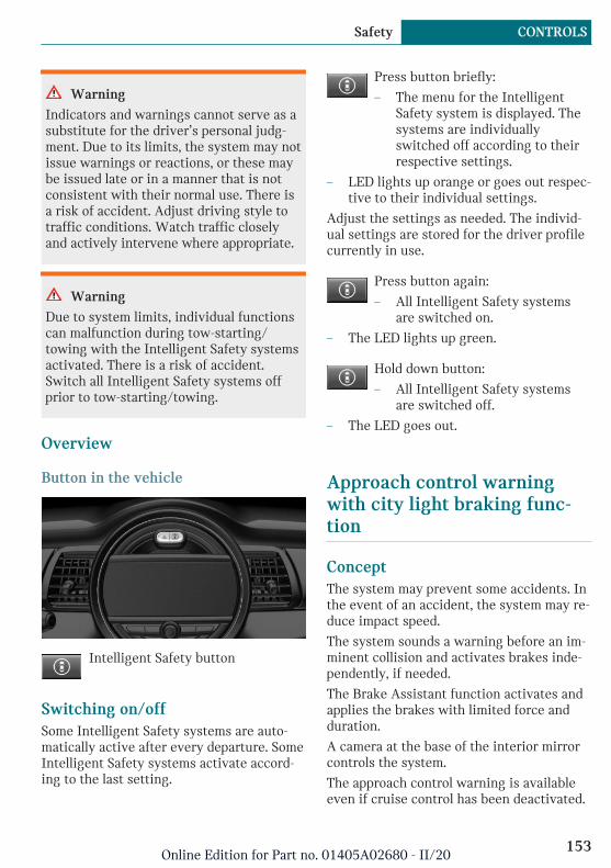
Warning
Indicators and warnings cannot serve as asubstitute for the driver’s personal judg-ment. Due to its limits, the system may notissue warnings or reactions, or these maybe issued late or in a manner that is notconsistent with their normal use. There isa risk of accident. Adjust driving style totraffic conditions. Watch traffic closelyand actively intervene where appropriate.
Warning
Due to system limits, individual functionscan malfunction during tow-starting/towing with the Intelligent Safety systemsactivated. There is a risk of accident.Switch all Intelligent Safety systems offprior to tow-starting/towing.
Overview
Button in the vehicle
Intelligent Safety button
Switching on/offSome Intelligent Safety systems are auto-matically active after every departure. SomeIntelligent Safety systems activate accord-ing to the last setting.
Press button briefly:
– The menu for the IntelligentSafety system is displayed. Thesystems are individuallyswitched off according to theirrespective settings.
– LED lights up orange or goes out respec-tive to their individual settings.
Adjust the settings as needed. The individ-ual settings are stored for the driver profilecurrently in use.
Press button again:
– All Intelligent Safety systemsare switched on.
– The LED lights up green.
Hold down button:
– All Intelligent Safety systemsare switched off.
– The LED goes out.
Approach control warningwith city light braking func-tion
ConceptThe system may prevent some accidents. Inthe event of an accident, the system may re-duce impact speed.
The system sounds a warning before an im-minent collision and activates brakes inde-pendently, if needed.
The Brake Assistant function activates andapplies the brakes with limited force andduration.
A camera at the base of the interior mirrorcontrols the system.
The approach control warning is availableeven if cruise control has been deactivated.
Seite 153
Safety CONTROLS
153Online Edition for Part no. 01405A02680 - II/20

With the vehicle approaching another vehi-cle intentionally, the approach control warn-ing and braking are delayed in order toavoid false system reactions.
General informationThe system warns at two levels of an immi-nent danger of collision at speeds from ap-prox. 3 mph/5 km/h. The timing of warn-ings may vary with the current drivingsituation.
Braking is performed at speeds up to ap-proximately 35 mph/60 km/h.
Detection range
Objects that the system can detect aretaken into account.
Safety information
Warning
The system cannot serve as a substitutefor the driver’s personal judgment in as-sessing visibility and traffic situation.There is a risk of accident. Adjust drivingstyle to traffic conditions. Watch trafficclosely and actively intervene where ap-propriate.
Warning
Indicators and warnings cannot serve as asubstitute for the driver’s personal judg-ment. Due to its limits, the system may notissue warnings or reactions, or these maybe issued late or in a manner that is notconsistent with their normal use. There isa risk of accident. Adjust driving style totraffic conditions. Watch traffic closelyand actively intervene where appropriate.
Warning
Due to system limits, individual functionscan malfunction during tow-starting/towing with the Intelligent Safety systemsactivated. There is a risk of accident.Switch all Intelligent Safety systems offprior to tow-starting/towing.
Overview
Button in the vehicle
Intelligent Safety button
Seite 154
CONTROLS Safety
154Online Edition for Part no. 01405A02680 - II/20

Camera
The camera is installed near the interiormirror.
Keep the windshield in front of the interiormirror clean and clear.
Switching on/off
Switching on automaticallyThe system is automatically active after ev-ery driving off.
Switching on/off manually
Press button briefly:
– The menu for the IntelligentSafety system is displayed. Thesystems are individuallyswitched off according to theirrespective settings.
– LED lights up orange or goes out respec-tive to their individual settings.
Adjust the settings as needed. The individ-ual settings are stored for the driver profilecurrently in use.
Press button again:
– All Intelligent Safety systemsare switched on.
– The LED lights up green.
Hold down button:
– All Intelligent Safety systemsare switched off.
– The LED goes out.
Setting the warning timeThe warning time can be set via the CentralInformation Display (CID).
1. "My MINI"
2. "Vehicle settings"
3. "Intelligent Safety"
4. "Warning time"
5. Select the desired setting.
The selected warning time is stored for thedriver profile currently in use.
Warning with braking function
DisplayA warning symbol appears in the instru-ment cluster and in the Head-up Display if acollision with a detected vehicle is immi-nent.
Symbol Measure
Symbol lights up red: prewarn-ing.
Brake and increase distance.
Symbol flashes red and anacoustic signal sounds: acutewarning.
Brake and make an evasive ma-neuver, if necessary.
PrewarningThis warning is provided, for instance whenthere is impending danger of a collision orthe distance to the vehicle ahead is toosmall.
If a prewarning is provided, respond bybraking as warranted.
Seite 155
Safety CONTROLS
155Online Edition for Part no. 01405A02680 - II/20

Acute warning with braking functionAn acute warning is displayed when thereis an imminent danger of collision due tothe vehicle approaching another object at ahigh speed.
The driver must intervene actively whenthere is an acute warning. If necessary, thedriver is assisted by a minor automaticbraking intervention in a possible risk ofcollision.
Acute warnings may be provided even whenthere has been no prior warning.
Braking interventionThe warning prompts the driver to inter-vene. During a warning, the maximum brak-ing force is used. In order to activate theBrake Assistant function, you must applythe brakes quickly and forcefully. If there isa risk of collision, the system may assistwith braking. When the vehicle is travelingat a low speed, the vehicle may come to acomplete stop.
The braking intervention can be interruptedby stepping on the accelerator pedal or byactively moving the steering wheel.
The system’s ability to detect objects maybe limited in some circumstances. Refer tothe information in this Owner’s Manual re-garding the limitations of the system andactively intervene as warranted.
System limits
Safety information
Warning
The system is designed to operate in cer-tain conditions and circumstances. Due toconditions or other factors, the systemmay not respond. There may be a risk ofaccident or risk of damage to property. Ac-tively intervene as warranted. Refer to the
information in this Owner’s Manual re-garding the scope of the system’s opera-tion and limitations.
Detection rangeThe system's detection potential is limited.
Thus, a system reaction might not come ormight come late.
The following situations may not be de-tected, for example:
– Slow moving vehicles when you ap-proach them at high speed.
– Vehicles that suddenly swerve in frontof you, or sharply decelerating vehicles.
– Vehicles with an unusual rear appear-ance.
– Two-wheeled vehicles ahead of you.
Functional limitationsThe system may not be fully functional inthe following situations:
– In heavy fog, wet conditions, or snow-fall.
– In tight curves.
– If the field of view of the camera or thewindshield is dirty or covered.
– If the driving stability control systemsare deactivated, for instance DSC OFF.
– Up to 10 seconds after activating thedrive-ready state via the Start/Stop but-ton.
– During calibration of the camera imme-diately after vehicle delivery.
– If there are constant blinding effects be-cause of oncoming light, for instancefrom the sun low in the sky.
Warning sensitivityThe more sensitive the warning settingsare, the more warnings are displayed.Therefore, there may also be an excess of
Seite 156
CONTROLS Safety
156Online Edition for Part no. 01405A02680 - II/20

premature or unjustified warnings and reac-tions.
Daytime pedestrian collisionmitigation
ConceptThe system may prevent some accidentswith pedestrians.
When driving at city speeds, the systemwill issue a warning if there is imminentrisk of a collision with pedestrians, and sup-port this with a light braking function.
The camera at the base of the interior mir-ror controls the system.
General informationIn sufficiently bright conditions, the systemissues a warning of a possible risk of colli-sion with pedestrians in the speed rangefrom approx. 6 mph/10 km/h to approx.35 mph/60 km/h
The system reacts to people who are withinthe detection range of the system.
Detection range
The detection area in front of the vehicle isdivided into two areas:
– Central area, arrow 1, directly in front ofthe vehicle.
– Expanded area, arrow 2, to the right andleft of the central area.
A collision is imminent if pedestrians are lo-cated within the central area. A warning isissued about pedestrians who are locatedwithin the extended area only if they aremoving in the direction of the central area.
Safety information
Warning
The system cannot serve as a substitutefor the driver’s personal judgment in as-sessing visibility and traffic situation.There is a risk of accident. Adjust drivingstyle to traffic conditions. Watch trafficclosely and actively intervene where ap-propriate.
Warning
Indicators and warnings cannot serve as asubstitute for the driver’s personal judg-ment. Due to its limits, the system may notissue warnings or reactions, or these maybe issued late or in a manner that is notconsistent with their normal use. There isa risk of accident. Adjust driving style totraffic conditions. Watch traffic closelyand actively intervene where appropriate.
Warning
Due to system limits, individual functionscan malfunction during tow-starting/towing with the Intelligent Safety systemsactivated. There is a risk of accident.Switch all Intelligent Safety systems offprior to tow-starting/towing.
Seite 157
Safety CONTROLS
157Online Edition for Part no. 01405A02680 - II/20

Overview
Button in the vehicle
Intelligent Safety button
Camera
The camera is installed near the interiormirror.
Keep the windshield in front of the interiormirror clean and clear.
Switching on/off
Switching on automaticallyThe system is automatically active after ev-ery driving off.
Switching on/off manually
Press button briefly:
– The menu for the IntelligentSafety system is displayed. Thesystems are individually
switched off according to theirrespective settings.
– LED lights up orange or goes out respec-tive to their individual settings.
Adjust the settings as needed. The individ-ual settings are stored for the driver profilecurrently in use.
Press button again:
– All Intelligent Safety systemsare switched on.
– The LED lights up green.
Hold down button:
– All Intelligent Safety systemsare switched off.
– The LED goes out.
Warning with braking function
DisplayIf a collision with a detected person is im-minent, a warning symbol appears on theinstrument cluster and in the Head-up Dis-play.
The red symbol is displayed and asignal sounds.
Intervene immediately by braking ormake an evasive maneuver.
Braking interventionThe warning prompts the driver to inter-vene. During a warning, the maximum brak-ing force is used. In order to activate theBrake Assistant function, you must applythe brakes quickly and forcefully. If there isa risk of collision, the system may assistwith braking. When the vehicle is travelingat a low speed, the vehicle may come to acomplete stop.
Seite 158
CONTROLS Safety
158Online Edition for Part no. 01405A02680 - II/20
The braking intervention can be interruptedby stepping on the accelerator pedal or byactively moving the steering wheel.
The system’s ability to detect objects maybe limited in some circumstances. Refer tothe information in this Owner’s Manual re-garding the limitations of the system andactively intervene as warranted.
System limits
Safety information
Warning
The system is designed to operate in cer-tain conditions and circumstances. Due toconditions or other factors, the systemmay not respond. There may be a risk ofaccident or risk of damage to property. Ac-tively intervene as warranted. Refer to theinformation in this Owner’s Manual re-garding the scope of the system’s opera-tion and limitations.
Detection rangeThe detection potential of the camera is lim-ited.
Thus, a warning might not be issued or beissued late.
The following situations may not be de-tected, for example:
– Partially covered pedestrians.
– Pedestrians that are not detected assuch because of the viewing angle orcontour.
– Pedestrians outside of the detectionrange.
– Pedestrians having a body size less than32 in/80 cm.
Functional limitationsThe system may not be fully functional ormay not be available in the following situa-tions:
– In heavy fog, wet conditions, or snow-fall.
– In tight curves.
– If the field of view of the camera or thewindshield is dirty or covered.
– If the driving stability control systemsare deactivated, for instance DSC OFF.
– Up to 10 seconds after activating thedrive-ready state via the Start/Stop but-ton.
– During calibration of the camera imme-diately after vehicle delivery.
– If there are constant blinding effects be-cause of oncoming light, for instancefrom the sun low in the sky.
– When it is dark outside.
Fatigue alert
ConceptThe system can detect decreasing alertnessor fatigue of the driver during long, monoto-nous trips, for instance on highways. In thissituation, it is recommended that the drivertakes a break.
Safety information
Warning
The system cannot serve as a substitutefor the driver’s personal judgment in as-sessing one's physical state. An increasinglack of alertness or fatigue may not be de-tected or not be detected in time. There isa risk of accident. Make sure that the
Seite 159
Safety CONTROLS
159Online Edition for Part no. 01405A02680 - II/20

driver is rested and alert. Adjust drivingstyle to traffic conditions.
FunctionThe system is switched on each time the en-gine is started and cannot be switched off.
After travel has begun, the system monitorscertain aspects of the driver's behavior, sothat decreasing alertness or fatigue can bedetected.
This procedure takes the following criteriainto account:
– Personal driving style, for instancesteering behavior.
– Driving conditions, for instance time,length of trip.
Starting at approximately 43 mph/70 km/h,the system is active and can display a rec-ommendation to take a break.
Break recommendationIf the driver becomes less alert or fatigued,a message is displayed in the Control Dis-play with the recommendation to take abreak.
A recommendation to take a break is dis-played only once during an uninterruptedtrip.
After a break, another recommendation totake a break cannot be displayed until afterapproximately 45 minutes.
System limitsThe function may be limited in the follow-ing situations and may issue an incorrectwarning or no warning at all:
– When the clock is set incorrectly.
– When the vehicle speed is mainly belowabout 43 mph/70 km/h.
– With a sporty driving style, such as dur-ing rapid acceleration or when corner-ing fast.
– In active driving situations, such aswhen changing lanes frequently.
– When the road surface is poor.
– In the event of strong side winds.
The system is reset approx. 45 minutes af-ter parking the vehicle, for instance in thecase of a break during longer trips on high-ways.
PostCrash – iBrake
ConceptIn the event of an accident, the system canbring the vehicle to a halt automaticallywithout intervention by the driver in cer-tain situations. This can reduce the risk of afurther collision and the consequencesthereof.
At standstillAfter coming to a halt, the brake is releasedautomatically. Secure the vehicle againstrolling.
Harder vehicle brakingIn certain situations, it can be necessary tobring the vehicle to a halt more quickly thanthe Brake Assistant allows.
To do this, quickly apply extra force to thebrake. For a brief period, the braking pres-sure will be higher than the braking pres-sure that is achieved by the automatic brak-ing function. This interrupts automaticbraking.
Seite 160
CONTROLS Safety
160Online Edition for Part no. 01405A02680 - II/20
Interrupting automatic brakingIt can be necessary to interrupt automaticbraking in certain situations, for instancefor an evasive maneuver.
Interrupt automatic braking:
– By pressing the brake pedal.
– By pressing the accelerator pedal.
Seite 161
Safety CONTROLS
161Online Edition for Part no. 01405A02680 - II/20

Driving stability control systems
Vehicle features and options
This chapter describes all standard, country-specific and optional features offered withthe series. It also describes features andfunctions that are not necessarily availablein your vehicle, e.g., due to the selected op-tions or country versions. This also appliesto safety-related functions and systems.When using these functions and systems,the applicable laws and regulations must beobserved.
Antilock Braking System ABS
ABS prevents locking of the wheels duringbraking.
The vehicle maintains its steering powereven during full brake applications, whichincreases the active safety.
ABS is ready when vehicle is ready to drive.
Brake assistant
When you apply the brakes rapidly, this sys-tem automatically boosts the vehicle brak-ing capability to the furthest possible ex-tent. It reduces the braking distance to aminimum during an emergency stop. Thissystem utilizes all of the capabilities pro-vided by the Antilock Brake System ABS.
Do not reduce the pressure on the brakepedal for the duration of the emergencystop.
Energy recovery
General informationIn the event of danger, such as with lockedwheels, energy recovery is reduced in orderto prevent unstable driving situations.
Safety information
Warning
Without energy recovery, there is no brak-ing power of the electric motor available.The vehicle could roll further than antici-pated. There is a risk of accident. Adjustdriving style to traffic conditions. Watchtraffic closely and actively intervenewhere appropriate.
DSC Dynamic Stability Control
ConceptWithin the physical limits, the system helpsto keep the vehicle on a steady course byreducing engine speed and by applyingbrakes to the individual wheels.
General informationDSC detects the following unstable drivingconditions, for instance:
– Fishtailing, which can lead to oversteer-ing.
– Loss of traction of the front wheels,which can lead to understeering.
Dynamic Traction Control DTC, refer topage 163, is a version of the DSC where for-ward momentum is optimized.
Seite 162
CONTROLS Driving stability control systems
162Online Edition for Part no. 01405A02680 - II/20
Safety information
Warning
The system cannot serve as a substitutefor the driver’s personal judgment in as-sessing the traffic conditions. Based onthe limits of the system, it cannot inde-pendently react to all traffic situations.There is a risk of accident. Adjust drivingstyle to traffic conditions. Watch trafficclosely and actively intervene where ap-propriate.
Warning
When driving with a roof load, for in-stance with roof-mounted luggage rack,the vehicle's center of gravity is higher,which increases the risk of the vehicle tip-ping in critical driving situations. Theremay be a risk of accident or risk of damageto property. Do not deactivate DSC Dy-namic Stability Control when driving withroof load.
Indicator/warning lightsThe indicator light flashes: DSC con-trols the drive and braking forces.
The indicator light lights up: DSC hasmalfunctioned.
Deactivating DSC: DSC OFF
General informationWhen DSC is deactivated, driving stabilityis reduced during acceleration and whendriving in curves.
To increase vehicle stability, activate DSCagain as soon as possible.
Deactivating DSC
Press and hold this button but notlonger than approx. 10 seconds, un-til the indicator light for DSC OFF
lights up in the instrument cluster and dis-plays DSC OFF.
DSC is switched off.
Activating DSC
Press the button.
DSC OFF and the DSC OFF indicatorlight go out.
Indicator/warning lightsWhen DSC is deactivated, DSC OFF is dis-played in the instrument cluster.
The indicator light lights up: DSC isdeactivated.
Automatic activationWhen DSC is deactivated, automatic activa-tion occurs in the following situations:
– The vehicle has a flat tire.
– When activating cruise control in theTRACTION or DSC OFF settings.
DTC Dynamic Traction Con-trol
ConceptDTC is a version of the DSC Dynamic Stabil-ity Control where forward momentum is op-timized.
The system ensures maximum headway onspecial road conditions, for instance unp-lowed snowy roads or loose road surfaces,but with somewhat limited vehicle stability.
Seite 163
Driving stability control systems CONTROLS
163Online Edition for Part no. 01405A02680 - II/20
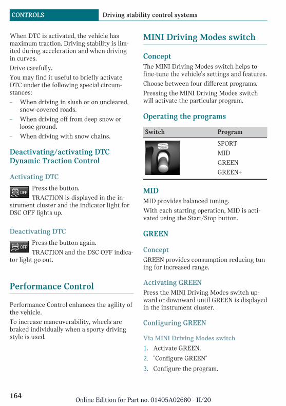
When DTC is activated, the vehicle hasmaximum traction. Driving stability is lim-ited during acceleration and when drivingin curves.
Drive carefully.
You may find it useful to briefly activateDTC under the following special circum-stances:
– When driving in slush or on uncleared,snow-covered roads.
– When driving off from deep snow orloose ground.
– When driving with snow chains.
Deactivating/activating DTCDynamic Traction Control
Activating DTC
Press the button.
TRACTION is displayed in the in-strument cluster and the indicator light forDSC OFF lights up.
Deactivating DTC
Press the button again.
TRACTION and the DSC OFF indica-tor light go out.
Performance Control
Performance Control enhances the agility ofthe vehicle.
To increase maneuverability, wheels arebraked individually when a sporty drivingstyle is used.
MINI Driving Modes switch
ConceptThe MINI Driving Modes switch helps tofine-tune the vehicle's settings and features.
Choose between four different programs.
Pressing the MINI Driving Modes switchwill activate the particular program.
Operating the programs
Switch Program
SPORT
MID
GREEN
GREEN+
MIDMID provides balanced tuning.
With each starting operation, MID is acti-vated using the Start/Stop button.
GREEN
ConceptGREEN provides consumption reducing tun-ing for increased range.
Activating GREENPress the MINI Driving Modes switch up-ward or downward until GREEN is displayedin the instrument cluster.
Configuring GREEN
Via MINI Driving Modes switch
1. Activate GREEN.
2. "Configure GREEN"
3. Configure the program.
Seite 164
CONTROLS Driving stability control systems
164Online Edition for Part no. 01405A02680 - II/20

This configuration is retrieved whenGREEN is activated.
Via the Central Information Display (CID)
1. "My MINI"
2. "Vehicle settings"
3. If necessary, "Driving mode"
4. "Configure GREEN"
5. Select the desired setting.
This configuration is retrieved whenGREEN is activated.
GREEN+
ConceptGREEN provides consistent tuning to maxi-mize range.
During the activation, some comfort func-tions will also be limited or deactivated.
Activating GREEN+Press the MINI Driving Modes switch up-ward or downward until GREEN+ is dis-played in the instrument cluster.
SPORT
ConceptConsistently sporty tuning of the drivetrainfor greater driving agility.
Activating SPORTPress the MINI Driving Modes switch up-ward or downward until SPORT is displayedin the instrument cluster.
Configuring driving programSettings can be made for the following driv-ing programs in Driving mode:
– GREEN, refer to page 164.
– SPORT, refer to page 165.
Displays
Program selection
Pressing the MINI DrivingModes switch displays a list ofprograms, which can be se-lected.
Selected program
The instrument cluster dis-plays the selected program.
Drive-off assistant
ConceptThis system supports driving off on uphillgrades. The parking brake is not required.
Driving off with the drive-offassistant1. Hold the vehicle in place with the foot
brake.
2. Release the foot brake and drive offwithout delay.
After the foot brake is released, the vehicleis held in place for approx. 2 seconds.
Servotronic
Servotronic is a speed-dependent powersteering function.
The system provides the steering force withmore support at low speeds than at higherones. This makes it easier to park, for in-stance, and makes steering firmer whendriving at faster speeds.
Seite 165
Driving stability control systems CONTROLS
165Online Edition for Part no. 01405A02680 - II/20
Furthermore, the steering force adapts ac-cording to the driving program, so that afirm, sporty feel or a comfortable steeringresponse is conveyed.
Seite 166
CONTROLS Driving stability control systems
166Online Edition for Part no. 01405A02680 - II/20

Driving comfort
Vehicle features and options
This chapter describes all standard, country-specific and optional features offered withthe series. It also describes features andfunctions that are not necessarily availablein your vehicle, e.g., due to the selected op-tions or country versions. This also appliesto safety-related functions and systems.When using these functions and systems,the applicable laws and regulations must beobserved.
Cruise control
ConceptUsing this system, a desired speed can beadjusted using the buttons on the steeringwheel. The system maintains the desiredspeed. The system accelerates and brakesautomatically as needed.
General informationThe system is functional at speeds begin-ning at approx. 20 mph/30 km/h.
Depending on the settings, the cruise con-trol settings many change under certainconditions.
Safety information
Warning
The system cannot serve as a substitutefor the driver’s personal judgment in as-sessing the traffic conditions. Based onthe limits of the system, it cannot inde-pendently react to all traffic situations.There is a risk of accident. Adjust driving
style to traffic conditions. Watch trafficclosely and actively intervene where ap-propriate.
Warning
The use of the system can lead to an in-creased risk of accidents in the followingsituations, for instance:
– On winding roads.
– In heavy traffic.
– On slippery roads, in fog, snow, orwet conditions, or on a loose roadsurface.
There may be a risk of accident or risk ofdamage to property. Only use the system ifdriving at constant speed is possible.
Overview
Buttons on the steering wheel
Button Function
Cruise control on/off, refer topage 168.
Store speed, refer to page 168.
Pause cruise control, refer topage 168.
Continue cruise control with thelast setting, refer to page 169.
Increase speed, refer topage 168.
Reduce speed, refer to page 168.
Seite 167
Driving comfort CONTROLS
167Online Edition for Part no. 01405A02680 - II/20
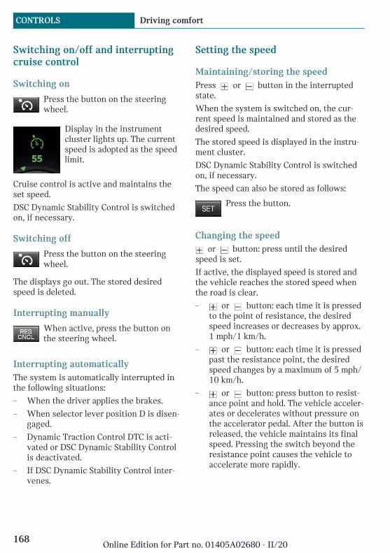
Switching on/off and interruptingcruise control
Switching on
Press the button on the steeringwheel.
Display in the instrumentcluster lights up. The currentspeed is adopted as the speedlimit.
Cruise control is active and maintains theset speed.
DSC Dynamic Stability Control is switchedon, if necessary.
Switching off
Press the button on the steeringwheel.
The displays go out. The stored desiredspeed is deleted.
Interrupting manually
When active, press the button onthe steering wheel.
Interrupting automaticallyThe system is automatically interrupted inthe following situations:
– When the driver applies the brakes.
– When selector lever position D is disen-gaged.
– Dynamic Traction Control DTC is acti-vated or DSC Dynamic Stability Controlis deactivated.
– If DSC Dynamic Stability Control inter-venes.
Setting the speed
Maintaining/storing the speedPress or button in the interruptedstate.
When the system is switched on, the cur-rent speed is maintained and stored as thedesired speed.
The stored speed is displayed in the instru-ment cluster.
DSC Dynamic Stability Control is switchedon, if necessary.
The speed can also be stored as follows:
Press the button.
Changing the speed or button: press until the desired
speed is set.
If active, the displayed speed is stored andthe vehicle reaches the stored speed whenthe road is clear.
– or button: each time it is pressedto the point of resistance, the desiredspeed increases or decreases by approx.1 mph/1 km/h.
– or button: each time it is pressedpast the resistance point, the desiredspeed changes by a maximum of 5 mph/10 km/h.
– or button: press button to resist-ance point and hold. The vehicle acceler-ates or decelerates without pressure onthe accelerator pedal. After the button isreleased, the vehicle maintains its finalspeed. Pressing the switch beyond theresistance point causes the vehicle toaccelerate more rapidly.
Seite 168
CONTROLS Driving comfort
168Online Edition for Part no. 01405A02680 - II/20

Continuing cruise control
General informationAn interrupted cruise control can be contin-ued by calling up the stored speed.
Make sure that the difference between cur-rent speed and stored speed is not too largebefore calling up the stored speed. Other-wise, unintentional braking or acceleratingmay occur.
Calling up the stored speed
Press the button on the steeringwheel.
The stored speed is reached again and main-tained.
Displays in the instrument cluster
Indicator light
The indicator in the instru-ment cluster lights up: the sys-tem is switched on.
Desired speed and stored speed
The desired speed is displayedtogether with the symbol.
– Display lights up green:system is active, the dis-play indicates the desiredspeed.
– Display lights up gray: system is inter-rupted, the display indicates the storedspeed.
– No display: system is switched off.
System limits
Engine powerThe desired speed is also maintained down-hill, but may not be maintained on uphillgrades if engine power is insufficient.
PDC Park Distance Control
ConceptPDC is a support when parking. The systemdetects objects behind the vehicle. If the ve-hicle is equipped with front PDC, objects infront of the vehicle are detected too. Ob-jects that you are approaching slowly are in-dicated by signal tones and a visual display.
General informationThe ultrasound sensors for measuring thedistances are located in the bumpers.
The delete range, depending on obstaclesand environmental conditions, is approx.6 ft/2 m.
An acoustic warning is first given in the fol-lowing situations:
– By the front middle sensors and the twocorner sensors at approx. 24 in/60 cmfrom the object.
– By the rear middle sensors at ap-prox. 5 ft/1.50 m from the object.
– When a collision is imminent.
Safety information
Warning
The system cannot serve as a substitutefor the driver’s personal judgment in as-sessing the traffic conditions. There is arisk of accident. Adjust driving style totraffic conditions. Watch traffic and vehi-
Seite 169
Driving comfort CONTROLS
169Online Edition for Part no. 01405A02680 - II/20
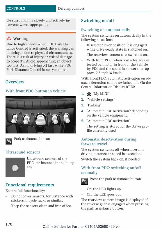
cle surroundings closely and actively in-tervene where appropriate.
Warning
Due to high speeds when PDC Park Dis-tance Control is activated, the warning canbe delayed due to physical circumstances.There is a risk of injury or risk of damageto property. Avoid approaching an objecttoo fast. Avoid driving off fast while PDCPark Distance Control is not yet active.
Overview
With front PDC: button in vehicle
Park assistance button
Ultrasound sensors
Ultrasound sensors of thePDC, for instance in the bump-ers.
Functional requirementsEnsure full functionality:
– Do not cover sensors, for instance withstickers, bicycle racks or similar.
– Keep the sensors clean and free of ice.
Switching on/off
Switching on automaticallyThe system switches on automatically in thefollowing situations:
– If selector lever position R is engagedwhile drive-ready state is switched on.
The rearview camera also switches on.
– With front PDC: when obstacles are de-tected behind or in front of the vehicleby PDC and the speed is slower than ap-prox. 2.5 mph/4 km/h.
With front PDC: automatic activation on ob-stacle detection can be switched off. Via theCentral Information Display (CID):
1. "My MINI"
2. "Vehicle settings"
3. "Parking"
4. "Automatic PDC activation": dependingon the vehicle equipment.
5. "Automatic PDC activation"
The setting is stored for the driver pro-file currently used.
Automatic deactivation duringforward travelThe system switches off when a certaindriving distance or speed is exceeded.
Switch the system back on, if needed.
With front PDC: switching on/offmanually
Press the park assistance button.
– On: the LED lights up.
– Off: the LED goes out.
The rearview camera image is displayed ifthe reverse gear is engaged when pressingthe park assistance button.
Seite 170
CONTROLS Driving comfort
170Online Edition for Part no. 01405A02680 - II/20

Depending on the equipment version, thesystem cannot be switched off manually ifthe reverse gear is engaged.
Warning
Signal tonesAn intermittent tone indicates when the ve-hicle is approaching an object. E.g., when anobject is detected to the left rear of the ve-hicle, a signal tone sounds from the left rearspeaker.
The shorter the distance to the object, theshorter the intervals.
When the distance to a detected object isless than approx. 10 inches/25 cm, a contin-uous tone is sounded.
With front PDC: when objects are simulta-neously located both in front of and behindthe vehicle, an alternating continuous sig-nal is sounded.
VolumeThe ratio of the PDC signal tone volume tothe entertainment volume can be adjusted.
1. "My MINI"
2. "System settings"
3. "Tone"
4. "Volume settings"
5. "PDC"
6. Set the desired value.
The setting is stored for the driver profilecurrently used.
Visual warningThe approach of the vehicle to an object canbe shown on the Control Display. Objectsthat are farther away are already displayedon the Control Display before a signalsounds.
A display appears as soon as Park DistanceControl (PDC) is activated.
The range of the sensors is represented incolors: red, green and yellow.
When the image of the rearview camera isdisplayed, the switch can be made to PDC:
"Rear view camera"
System limits
Safety information
Warning
The system is designed to operate in cer-tain conditions and circumstances. Due toconditions or other factors, the systemmay not respond. There may be a risk ofaccident or risk of damage to property. Ac-tively intervene as warranted. Refer to theinformation in this Owner’s Manual re-garding the scope of the system’s opera-tion and limitations.
Limits of ultrasonic measurementThe detection of objects with ultrasonicmeasurements can run into physical limits,for instance under the following conditions:
– For small children and animals.
– For persons with certain clothing, for in-stance coats.
– With external interference of the ultra-sound, for instance from passing vehi-cles or loud machines.
– When sensors are dirty, iced over, dam-aged or out of position.
– If cargo protrudes.
– Under certain weather conditions suchas high relative humidity, wet condi-tions, snowfall, extreme heat, or strongwind.
Seite 171
Driving comfort CONTROLS
171Online Edition for Part no. 01405A02680 - II/20

– With tow bars and trailer couplings ofother vehicles.
– With thin or wedge-shaped objects.
– With moving objects.
– With elevated, protruding objects suchas ledges or cargo.
– With objects with corners and sharpedges.
– With objects with a fine surface struc-ture such as fences.
– For objects with porous surfaces.
– Low objects already displayed, for in-stance curbs, can move into the blindarea of the sensors before or after a con-tinuous tone sounds.
False warningsThe system may issue a warning under thefollowing conditions even though there isno obstacle within the detection range:
– In heavy rain.
– When sensors are very dirty or coveredwith ice.
– When sensors are covered in snow.
– On rough road surfaces.
– On uneven surfaces, such as speedbumps.
– In large buildings with right angles andsmooth walls, for instance in under-ground garages.
– In automatic vehicle washes.
– Due to heavy exhaust.
– Due to other ultrasound sources, for in-stance sweeping machines, high pres-sure steam cleaners or neon lights.
The malfunction is signaled by a contin-uous tone alternating between the frontand rear speakers. As soon as the mal-function due to other ultrasound sourcesis no longer present, the system is againfully functional.
With front PDC: to reduce false alarms,switch off automatic PDC activation on ob-stacle detection, for instance in vehiclewashes; see Switching on/off.
MalfunctionA Check Control message is displayed in theinstrument cluster.
Red symbol is displayed, and therange of the sensors is dimmed onthe Control Display.
PDC has failed. Have the system checked bya dealer's service center or another qualifiedservice center or repair shop.
Rearview camera
ConceptThe rearview camera provides assistance inparking and maneuvering backwards. Thearea behind the vehicle is shown on theControl Display.
Safety information
Warning
The system cannot serve as a substitutefor the driver’s personal judgment in as-sessing the traffic conditions. There is arisk of accident. Adjust driving style totraffic conditions. Watch traffic and vehi-cle surroundings closely and actively in-tervene where appropriate.
Seite 172
CONTROLS Driving comfort
172Online Edition for Part no. 01405A02680 - II/20
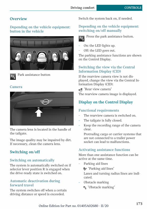
Overview
Depending on the vehicle equipment:button in the vehicle
Park assistance button
Camera
The camera lens is located in the handle ofthe tailgate.
The image quality may be impaired by dirt.If necessary, clean the camera lens.
Switching on/off
Switching on automaticallyThe system is automatically switched on ifselector lever position R is engaged whenthe drive-ready state is switched on.
Automatic deactivation duringforward travelThe system switches off when a certaindriving distance or speed is exceeded.
Switch the system back on, if needed.
Depending on the vehicle equipment:switching on/off manually
Press the park assistance button.
– On: the LED lights up.
– Off: the LED goes out.
The parking assistance functions are shownon the Control Display.
Switching the view via the CentralInformation Display (CID)If the rearview camera view is not dis-played, change the view via the Central In-formation Display (CID):
"Rear view camera"
The rearview camera image is displayed.
Display on the Control Display
Functional requirements– The rearview camera is switched on.
– The tailgate is fully closed.
– Keep the recording range of the cameraclear.
Protruding cargo or carrier systems thatare not connected to a trailer powersocket can lead to malfunctions.
Activating assistance functionsMore than one assistance function can beactive at the same time.
– Parking aid lines
"Parking aid lines"
Lanes and turning radius lines are indi-cated.
– Obstacle marking
"Obstacle marking"
Seite 173
Driving comfort CONTROLS
173Online Edition for Part no. 01405A02680 - II/20
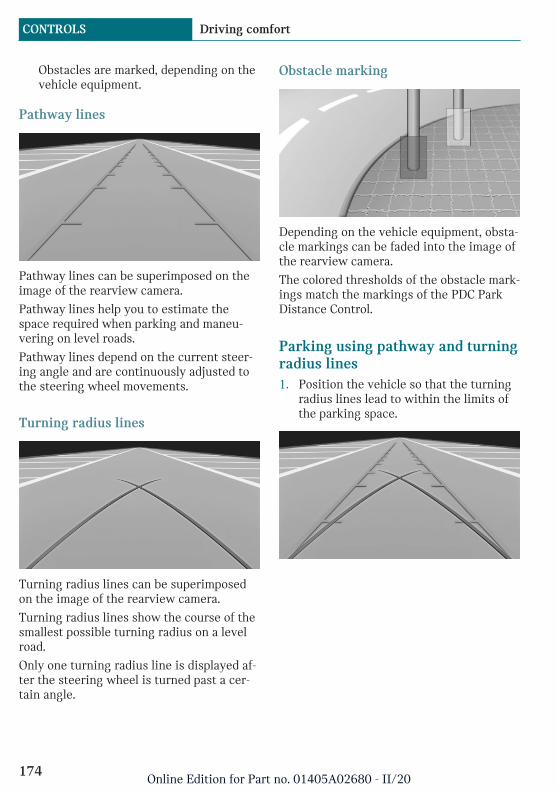
Obstacles are marked, depending on thevehicle equipment.
Pathway lines
Pathway lines can be superimposed on theimage of the rearview camera.
Pathway lines help you to estimate thespace required when parking and maneu-vering on level roads.
Pathway lines depend on the current steer-ing angle and are continuously adjusted tothe steering wheel movements.
Turning radius lines
Turning radius lines can be superimposedon the image of the rearview camera.
Turning radius lines show the course of thesmallest possible turning radius on a levelroad.
Only one turning radius line is displayed af-ter the steering wheel is turned past a cer-tain angle.
Obstacle marking
Depending on the vehicle equipment, obsta-cle markings can be faded into the image ofthe rearview camera.
The colored thresholds of the obstacle mark-ings match the markings of the PDC ParkDistance Control.
Parking using pathway and turningradius lines1. Position the vehicle so that the turning
radius lines lead to within the limits ofthe parking space.
Seite 174
CONTROLS Driving comfort
174Online Edition for Part no. 01405A02680 - II/20
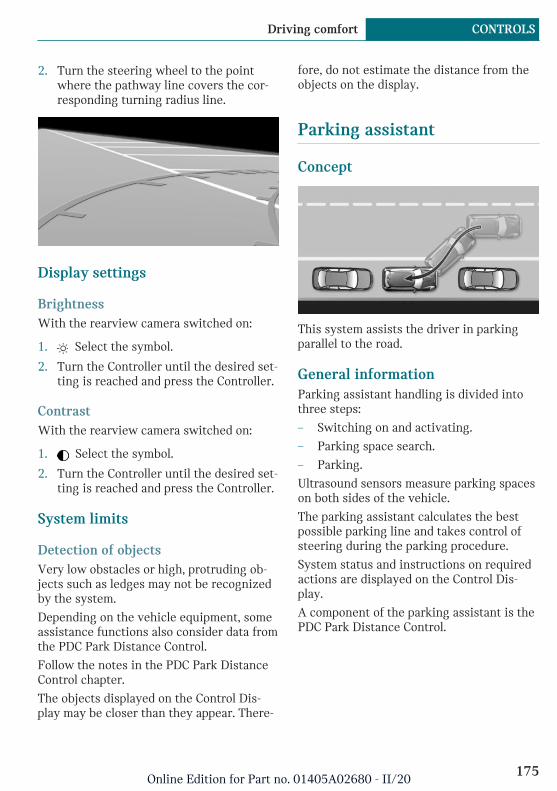
2. Turn the steering wheel to the pointwhere the pathway line covers the cor-responding turning radius line.
Display settings
BrightnessWith the rearview camera switched on:
1. Select the symbol.
2. Turn the Controller until the desired set-ting is reached and press the Controller.
ContrastWith the rearview camera switched on:
1. Select the symbol.
2. Turn the Controller until the desired set-ting is reached and press the Controller.
System limits
Detection of objectsVery low obstacles or high, protruding ob-jects such as ledges may not be recognizedby the system.
Depending on the vehicle equipment, someassistance functions also consider data fromthe PDC Park Distance Control.
Follow the notes in the PDC Park DistanceControl chapter.
The objects displayed on the Control Dis-play may be closer than they appear. There-
fore, do not estimate the distance from theobjects on the display.
Parking assistant
Concept
This system assists the driver in parkingparallel to the road.
General informationParking assistant handling is divided intothree steps:
– Switching on and activating.
– Parking space search.
– Parking.
Ultrasound sensors measure parking spaceson both sides of the vehicle.
The parking assistant calculates the bestpossible parking line and takes control ofsteering during the parking procedure.
System status and instructions on requiredactions are displayed on the Control Dis-play.
A component of the parking assistant is thePDC Park Distance Control.
Seite 175
Driving comfort CONTROLS
175Online Edition for Part no. 01405A02680 - II/20
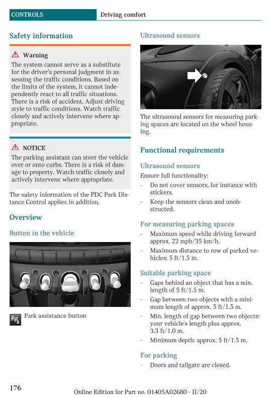
Safety information
Warning
The system cannot serve as a substitutefor the driver’s personal judgment in as-sessing the traffic conditions. Based onthe limits of the system, it cannot inde-pendently react to all traffic situations.There is a risk of accident. Adjust drivingstyle to traffic conditions. Watch trafficclosely and actively intervene where ap-propriate.
NOTICE
The parking assistant can steer the vehicleover or onto curbs. There is a risk of dam-age to property. Watch traffic closely andactively intervene where appropriate.
The safety information of the PDC Park Dis-tance Control applies in addition.
Overview
Button in the vehicle
Park assistance button
Ultrasound sensors
The ultrasound sensors for measuring park-ing spaces are located on the wheel hous-ing.
Functional requirements
Ultrasound sensorsEnsure full functionality:
– Do not cover sensors, for instance withstickers.
– Keep the sensors clean and unob-structed.
For measuring parking spaces– Maximum speed while driving forward
approx. 22 mph/35 km/h.
– Maximum distance to row of parked ve-hicles: 5 ft/1.5 m.
Suitable parking space– Gaps behind an object that has a min.
length of 5 ft/1.5 m.
– Gap between two objects with a mini-mum length of approx. 5 ft/1.5 m.
– Min. length of gap between two objects:your vehicle's length plus approx.3.3 ft/1.0 m.
– Minimum depth: approx. 5 ft/1.5 m.
For parking– Doors and tailgate are closed.
Seite 176
CONTROLS Driving comfort
176Online Edition for Part no. 01405A02680 - II/20

– The parking brake is released.
– When parking in parking spaces on thedriver's side, the corresponding turn sig-nal must be switched on.
Switching on and activating
Switching on with the button
Press the park assistance button.
The LED lights up.
The current status of the parking spacesearch is indicated on the Control Display.
Parking assistant is activated automati-cally.
Switching on with reverse gearShift into reverse.
The current status of the parking spacesearch is indicated on the Control Display.
To activate: "Parking Assistant"
Display on the Control Display
System activated/deactivated
Symbol Meaning
Gray: the system is not availa-ble.
White: the system is availablebut not activated.
The system is activated.
Parking space search and systemstatus
– Symbol P on the vehicle image: the park-ing assistant is activated and the park-ing space search is active.
– Control Display shows suitable parkingspaces at the edge of the road next tothe vehicle symbol. When the parkingassistant is active, suitable parkingspaces are highlighted.
– The parking procedure isactive. The system takesover the steering.
– Parking space search is always activewhenever the vehicle is moving forwardslow and straight, even if the system isdeactivated. When the system is deacti-vated, the displays on the Control Dis-play are shown in gray.
Parking using the parking assistant
Parking
1. Press the park assistance button orshift into reverse gear to switch on theparking assistant, refer to page 177. Ac-tivate the parking assistant, if needed.
Parking assistant is activated.
2. Pass the row of parked vehicles at aspeed of up to approx. 22 mph/35 km/h
Seite 177
Driving comfort CONTROLS
177Online Edition for Part no. 01405A02680 - II/20
and at a distance of maximum5 ft/1.5 m.
The status of the parking space searchand possible parking spaces are dis-played on the display, refer to page 177.
3. Follow the instructions on the display.
The best possible parking position willcome after gear change on the station-ary vehicle - wait for the automaticsteering wheel move.
The end of the parking procedure is in-dicated on the display.
4. Adjust the parking position yourself, ifneeded.
Interrupting manuallyThe parking assistant can be interrupted atany time:
– Press the park assistance button.
– "Parking Assistant"
Interrupting automaticallyThe system is interrupted automatically inthe following situations:
– If the driver grasps the steering wheelor takes over steering.
– If a gear is selected that does not matchthe instruction on the display.
– If the vehicle speed exceeds approx.6 mph/10 km/h.
– Possibly on snow-covered or slipperyroad surfaces.
– If a maximum number of parking at-tempts or the time taken for parking isexceeded.
– If the PDC Park Distance Control dis-plays clearances that are too small.
– When switching into other functions ofthe radio.
A Check Control message is displayed.
ResumingAn interrupted parking procedure can becontinued, if needed.
Reactivate the parking assistant, refer topage 177, and follow the instructions on thedisplay.
Switching offThe system can be switched off as follows:
– Press the park assistance button.
System limits
Safety information
Warning
The system is designed to operate in cer-tain conditions and circumstances. Due toconditions or other factors, the systemmay not respond. There may be a risk ofaccident or risk of damage to property. Ac-tively intervene as warranted. Refer to theinformation in this Owner’s Manual re-garding the scope of the system’s opera-tion and limitations.
No parking assistanceThe parking assistant does not offer assis-tance in the following situations:
– In tight curves.
Functional limitationsThe system may not be fully functional inthe following situations:
– On bumpy road surfaces such as gravelroads.
– On slippery ground.
– With accumulations of leaves/snow inthe parking space.
Seite 178
CONTROLS Driving comfort
178Online Edition for Part no. 01405A02680 - II/20
– With a mounted emergency wheel.
– With ditches or edges, for instance anedge of a port.
Limits of ultrasonic measurementThe detection of objects with ultrasonicmeasurements can run into physical limits,for instance under the following conditions:
– For small children and animals.
– For persons with certain clothing, for in-stance coats.
– With external interference of the ultra-sound, for instance from passing vehi-cles or loud machines.
– When sensors are dirty, iced over, dam-aged or out of position.
– If cargo protrudes.
– Under certain weather conditions suchas high relative humidity, wet condi-tions, snowfall, extreme heat, or strongwind.
– With tow bars and trailer couplings ofother vehicles.
– With thin or wedge-shaped objects.
– With moving objects.
– With elevated, protruding objects suchas ledges or cargo.
– With objects with corners and sharpedges.
– With objects with a fine surface struc-ture such as fences.
– For objects with porous surfaces.
– Low objects already displayed, for in-stance curbs, can move into the blindarea of the sensors before or after a con-tinuous tone sounds.
– The parking assistant may identify park-ing spaces that are not suitable for park-ing.
Tire sizeThe parking position may vary dependingon the tire size.
MalfunctionA Check Control message is displayed.
The parking assistant failed. Have the sys-tem checked by a dealer's service center oranother qualified service center or repairshop.
Seite 179
Driving comfort CONTROLS
179Online Edition for Part no. 01405A02680 - II/20
Climate control
Vehicle features and options
This chapter describes all standard, country-specific and optional features offered withthe series. It also describes features andfunctions that are not necessarily availablein your vehicle, e.g., due to the selected op-tions or country versions. This also appliesto safety-related functions and systems.When using these functions and systems,the applicable laws and regulations must beobserved.
Interior air quality
The air quality in the vehicle is improved bythe following components:
– Emission tested passenger compart-ment.
– Microfilter.
– Air conditioning system to control thetemperature, air flow and recirculated-air mode.
Depending on the equipment specification:
– Microfilter/activated-charcoal filter.
– Automatic climate control.
– Stationary climate control.
Seite 180
CONTROLS Climate control
180Online Edition for Part no. 01405A02680 - II/20

Automatic climate control
1 Temperature, left
2 Display
3 Air flow, AUTO intensity
4 AUTO program
5 Air distribution, manual
6 Display
7 Temperature, right
8 Seat heating, right 87
9 Maximum cooling
10 Air conditioning
11 Recirculated-air mode
12 Rear window defroster
13 To defrost windows and remove conden-sation
14 Seat heating, left 87
Climate control functions in detail
Switching the system on/off
Switching on
Set any air flow.
Switching off
Turn wheel for air flow to theleft until the control switchesoff.
Temperature
Concept
The automatic climate control achieves theset temperature as quickly as possible, if
Seite 181
Climate control CONTROLS
181Online Edition for Part no. 01405A02680 - II/20
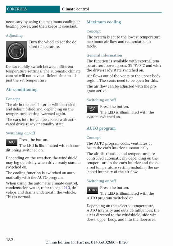
necessary by using the maximum cooling orheating power, and then keeps it constant.
Adjusting
Turn the wheel to set the de-sired temperature.
Do not rapidly switch between differenttemperature settings. The automatic climatecontrol will not have sufficient time to ad-just the set temperature.
Air conditioning
Concept
The air in the car's interior will be cooledand dehumidified and, depending on thetemperature setting, warmed again.
The car's interior can be cooled with acti-vated drive-ready or standby state.
Switching on/off
Press the button.
The LED is illuminated with air con-ditioning switched on.
Depending on the weather, the windshieldmay fog up briefly when drive-ready state isswitched on.
The cooling function is switched on auto-matically with the AUTO program.
When using the automatic climate control,condensation water, refer to page 210, de-velops and drains underneath the vehicle.This is normal.
Maximum cooling
Concept
The system is set to the lowest temperature,maximum air flow and recirculated-airmode.
General information
The function is available with external tem-peratures above approx. 32 ℉/0 ℃ and withthe drive-ready state switched on.
Air flows out of the vents to the upper bodyregion. The vents need to be open for this.
The air flow can be adjusted with the pro-gram active.
Switching on/off
Press the button.
The LED is illuminated with thesystem switched on.
AUTO program
Concept
The AUTO program cools, ventilates orheats the car's interior automatically.
The air distribution and temperature arecontrolled automatically depending on thetemperature in the car's interior and the de-sired temperature setting including the se-lected intensity of the air flow.
Switching on/off
Press the button.
The LED is illuminated with theAUTO program switched on.
Depending on the selected temperature,AUTO intensity and outside influences, theair is directed to the windshield, side win-dows, upper body, and into the floor area.
Seite 182
CONTROLS Climate control
182Online Edition for Part no. 01405A02680 - II/20

Point the side vents toward the side win-dows.
The following features are switched on au-tomatically with the AUTO program:
– The air conditioning, refer to page 182.
To switch off the program: press the buttonagain or manually adjust the air distribu-tion.
Intensity
With the AUTO program activated, the au-tomatic intensity control can be changed.
Turn the ring to set the de-sired intensity from soft to in-tensive.
The set intensity is displayed via the posi-tion of the illuminated LED segment.
Recirculated-air mode
Concept
You may react to unpleasant odors or pollu-tants in the immediate environment by tem-porarily suspending the supply of outsideair. The system then recirculates the airflow within the vehicle.
Operation
Press the button:
The LED is illuminated when recir-culated-air mode is switched on. The supplyof outside air is shut off.
When recirculated-air mode is switched off,fresh air is directed into the vehicle's inte-rior.
To prevent window condensation, recircu-lated-air mode switches off automatically af-ter a certain amount of time, depending onthe external temperature.
With constant recirculated-air mode, the airquality in the car's interior deteriorates andwindow fogging increases.
If the windows fog over, switch off recircu-lated-air mode and increase the air flow, ifneeded.
Adjusting the air flow manually
Concept
The air flow for climate control can be ad-justed manually.
General information
To adjust the air flow manually switch offAUTO program first.
Operation
Turn the ring to set the de-sired air flow.
The manually adjusted air flow is displayedvia illuminated LED segments.
The air flow of the automatic climate con-trol may be reduced automatically to savebattery power.
Adjusting the air distributionmanually
Concept
The air distribution for climate control canbe adjusted manually.
Operation
Press the button repeatedly to se-lect a program:
– Windows, upper body region, and floorarea.
– Upper body region and floor area.
Seite 183
Climate control CONTROLS
183Online Edition for Part no. 01405A02680 - II/20

– Floor area.
– Windows and floor area.
– Windows.
– Windows and upper body region.
– Upper body region.
To defrost windows and removecondensation
Concept
Ice and condensation are quickly removedfrom the windshield and the front side win-dows.
Switching on/off
Press the button.
The LED is illuminated with thesystem switched on.
The air flow can be adjusted with the pro-gram active.
If there is window condensation, switch onthe air conditioning too.
Rear window defroster
Press the button. The LED lights up.
The rear window defroster switchesoff automatically after a certain period oftime.
When GREEN Mode is activated, the heat-ing output is reduced.
Microfilter/activated-charcoal filterIn external and recirculated-air mode, themicrofilter/activated charcoal filter filtersdust, pollen, and gaseous pollutants out ofthe air.
Have this filter changed during vehiclemaintenance, refer to page 248.
Ventilation
SettingThe air flow directions can be individuallyadjusted:
– Direct ventilation:
The air flow is directly pointed onto theperson. The air flow heats or cools no-ticeably, depending on the adjusted tem-perature.
– Indirect ventilation:
If the vents are fully or partly closed, theair is directly routed into the car's inte-rior.
Front ventilation
– Turn knob for continuous opening andclosing of the vents.
– Swivel the vents to alter the direction ofthe vent flow, arrows.
Stationary climate control
ConceptStationary climate control cools or heats thecar's interior prior to departure to a com-fortable temperature.
The system automatically cools, vents, orheats depending on the internal and exter-nal temperature. Snow and ice may be re-moved more easily.
Seite 184
CONTROLS Climate control
184Online Edition for Part no. 01405A02680 - II/20
General informationThe stationary climate control can beswitched on and off directly or via a presetdeparture time:
– Direct operation, refer to page 185.
– Preselected departure times, refer topage 185.
The air automatically exits through thevents to the windshield, the side windows,the upper body region and into the floorarea.
The system switches off automatically aftera certain period of time.
If stationary climate control is used duringthe charging process, less air conditioningcapacity will be required while driving. Thisoptimizes the range.
Functional requirements– Drive-ready state deactivated.
– High-voltage battery sufficientlycharged or charging cable connected.
If the high-voltage battery is heavily dis-charged, it can take some time after con-necting the charging cable, until the sta-tionary climate control will befunctional.
– Direct operation or departure time pre-selected: depends on internal, external,and set desired temperature.
Make sure that the vehicle's date andtime are set correctly.
– To ensure the minimum range of the ve-hicle, the stationary climate control maybe automatically switched off, for in-stance after repeated activation or dueto an insufficient state of charge of thehigh-voltage battery. After the station-ary climate control is switched off dueto an insufficient state of charge, chargethe high-voltage battery and switch the
drive-ready state on and off. The station-ary climate control is available again.
– The vents are open to allow air to flowout.
Switching on/off directly
ConceptThe system can be switched on or off di-rectly.
The system switches off automatically aftera certain period of time.
Via the Central Information Display(CID)The system can be switched on or off viathe Central Information Display (CID).
1. "My MINI"
2. "Vehicle settings"
3. If necessary, "Climate functions"
4. "Activate comfort climate"
5. "Activate now"
Climate control for departure time
ConceptDifferent departure times can be set to en-sure a comfortable interior temperature inthe vehicle at the time of departure.
The activation time is automatically deter-mined based on the temperature.
The system promptly switches on before theselected departure time.
The departure time is preselected in twosteps:
– Set departure times.
– Activate departure times.
Seite 185
Climate control CONTROLS
185Online Edition for Part no. 01405A02680 - II/20
Setting the departure timeVia the Central Information Display (CID):
1. "My MINI"
2. "Vehicle settings"
3. If necessary, "Climate functions"
4. "Activate comfort climate"
5. "Plan comfort climate"
6. Set the desired departure time, refer topage 225.
Activating the departure timeIf a departure time is to influence theswitching on of the stationary climate con-trol, the respective departure time must beactivated first.
Via the Central Information Display (CID):
1. "My MINI"
2. "Vehicle settings"
3. If necessary, "Climate functions"
4. "Activate comfort climate"
5. "Plan comfort climate"
6. "Precondition for departure"
7. Activate the desired departure time.
The symbol on the automatic climatecontrol lights up when the departure time isactivated.
The symbol on the automatic climatecontrol flashes when the stationary climatecontrol has been switched on.
Seite 186
CONTROLS Climate control
186Online Edition for Part no. 01405A02680 - II/20
Interior equipment
Vehicle features and options
This chapter describes all standard, country-specific and optional features offered withthe series. It also describes features andfunctions that are not necessarily availablein your vehicle, e.g., due to the selected op-tions or country versions. This also appliesto safety-related functions and systems.When using these functions and systems,the applicable laws and regulations must beobserved.
Integrated Universal RemoteControl
ConceptThe integrated Universal Remote Control inthe interior mirror can operate up to 3 func-tions of remote-controlled systems such asgarage door drives, barriers, or lighting sys-tems.
General informationThe Integrated Universal Remote Controlreplaces up to 3 different hand-held trans-mitters. To operate the remote control, thebuttons on the interior mirror must be pro-grammed with the desired functions. Thehand-held transmitter for the particular sys-tem is required in order to program the re-mote control.
Before selling the vehicle, delete the storedfunctions for the sake of security.
If possible, do not install the antenna of theremote-controlled system, e.g. the garagedoor drive, near metal objects to ensure thebest possible operation.
Safety information
Warning
The operation of remote-controlled sys-tems with the integrated universal remotecontrol, such as the garage door, may re-sult in injury, for example, body parts be-coming jammed in a garage door. There isa risk of injury or risk of damage to prop-erty. Make sure that the area of movementof the respective system is clear duringprogramming and operation. Also followthe safety information of the hand-heldtransmitter.
CompatibilityIf this symbol is printed on the pack-aging or in the owner's manual of thesystem to be controlled, the system
is generally compatible with the integratedUniversal Remote Control.
Additional questions are answered by:
– A dealer's service center or anotherqualified service center or repair shop.
– www.homelink.com on the Internet.
HomeLink is a registered trademark of Gen-tex Corporation.
Seite 187
Interior equipment CONTROLS
187Online Edition for Part no. 01405A02680 - II/20

Overview
1 LED
2 Programmable keys
3 Hand-held transmitters of the system
Programming
General informationThe battery of the hand-held transmittermust be fully charged at the time of pro-gramming to ensure an optimal range of theintegrated universal remote control.
1. Switch on the ignition.
2. Initial setup:
Press and hold the two outer buttons onthe interior mirror simultaneously forapproximately 10 seconds until the LEDflashes green rapidly. This erases all pro-gramming of the buttons on the interiormirror.
3. Press the interior mirror button to beprogrammed. The LED on the interiormirror will slowly begin flashing orange.
4. Hold the hand-held transmitter for thesystem to be used approx. 1 to 12 in/2.5to 30 cm away from the buttons on theinterior mirror. The required distancedepends on the hand-held transmitter.
5. Press and hold the button of the desiredfunction on the hand-held transmitter.
Canada: if programming with the hand-held transmitter was interrupted, hold
down the interior mirror button and re-peatedly press and release the hand-heldtransmitter button for 2 seconds.
6. – The LED lights up green: program-ming completed.
Release the button.
– The LED flashes fast: programmingis not complete.
Press the button on the interior mir-ror for 2 seconds and release. Per-form this procedure three times tocomplete the programming proce-dure.
If the integrated universal remotecontrol remains nonoperational, con-tinue with the special features forchange code wireless systems.
– LED does not flash green after60 seconds: programming not com-pleted.
Repeat steps 3 to 6.
To program other functions on other but-tons, repeat steps 3 to 5.
Special feature of the rolling codewireless systemIf you are unable to operate the system af-ter repeated programming, please check ifthe system to be controlled features a roll-ing code radio system.
Refer to the owner's manual for the system.
For systems with a rolling code radio sys-tem, the integrated Universal Remote Con-trol and the system also have to besynchronized.
Please read the owner's manual to find outhow to synchronize the system.
Synchronizing is easier with the aid of asecond person.
Seite 188
CONTROLS Interior equipment
188Online Edition for Part no. 01405A02680 - II/20

Synchronizing the universal remote controlwith the system:
1. Park the vehicle within range of the re-mote-controlled system.
2. Program the relevant button on the inte-rior mirror as described.
3. Locate and press the synchronizing but-ton on the system being programmed,e.g. at the garage gate. You have approx.30 seconds for the next step.
4. Hold down the programmed button onthe interior mirror for approximately3 seconds and then release it. If neces-sary, repeat this step up to three timesin order to finish synchronization. Oncesynchronization is complete, the pro-grammed function will be carried out.
Reprogramming individual buttons1. Switch on the ignition.
2. Press and hold the interior mirror but-ton to be programmed.
3. As soon as the LED on the interior mir-ror flashes orange after approx. 20 sec-onds, release the button.
4. Hold the hand-held transmitter for thesystem to be used approx. 1 to 12 in/2.5to 30 cm away from the buttons on theinterior mirror. The required distancedepends on the hand-held transmitter.
5. Press and hold the button of the desiredfunction on the hand-held transmitter.
Canada: if programming with the hand-held transmitter was interrupted, holddown the interior mirror button and re-peatedly press and release the hand-heldtransmitter button for 2 seconds.
6. The LED can light up in different ways.
– The LED lights up green: the pro-gramming procedure is completed.
Release the button.
– The LED flashes fast: the hand-heldtransmitter was detected but pro-gramming is not complete.
Press the button on the interior mir-ror for 2 seconds and release. Per-form this procedure three times tocomplete the programming proce-dure.
If the integrated universal remotecontrol remains nonoperational, con-tinue with the special features forchange code wireless systems.
– LED does not flash green after60 seconds: programming not com-pleted.
Repeat steps 3 to 6.
If the programming procedure is not com-pleted, the previous programming will re-main unchanged.
Operation
Warning
The operation of remote-controlled sys-tems with the integrated universal remotecontrol, such as the garage door, may re-sult in injury, for example, body parts be-coming jammed in a garage door. There isa risk of injury or risk of damage to prop-erty. Make sure that the area of movementof the respective system is clear duringprogramming and operation. Also followthe safety information of the hand-heldtransmitter.
The system, such as the garage door, can beoperated using the button on the interiormirror while the engine is running or whenthe ignition is started. To do this, hold downthe button within receiving range of thesystem until the function is activated. Theinterior mirror LED stays lit while the wire-less signal is being transmitted.
Seite 189
Interior equipment CONTROLS
189Online Edition for Part no. 01405A02680 - II/20
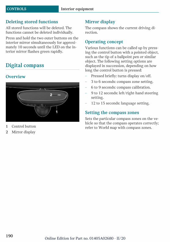
Deleting stored functionsAll stored functions will be deleted. Thefunctions cannot be deleted individually.
Press and hold the two outer buttons on theinterior mirror simultaneously for approxi-mately 10 seconds until the LED on the in-terior mirror flashes green rapidly.
Digital compass
Overview
1 Control button
2 Mirror display
Mirror displayThe compass shows the current driving di-rection.
Operating conceptVarious functions can be called up by press-ing the control button with a pointed object,such as the tip of a ballpoint pen or similarobject. The following setting options aredisplayed in succession, depending on howlong the control button is pressed:
– Pressed briefly: turns display on/off.
– 3 to 6 seconds: compass zone setting.
– 6 to 9 seconds: compass calibration.
– 9 to 12 seconds: left/right-hand steeringsetting.
– 12 to 15 seconds: language setting.
Setting the compass zonesSets the particular compass zones on the ve-hicle so that the compass operates correctly;refer to World map with compass zones.
Seite 190
CONTROLS Interior equipment
190Online Edition for Part no. 01405A02680 - II/20

World map with magnetic zones
Procedure1. Press and hold the control button for ap-
prox. 3 to 4 seconds. The number of theset compass zone appears in the mirror.
2. To change the zone setting, press thecontrol button quickly and repeatedlyuntil the number of the compass zonethat corresponds with your location ap-pears in the mirror.
The set zone is stored automatically. Thecompass is ready for use again after approx-imately 10 seconds.
Calibrating the digital compassThe digital compass must be calibrated inthe event of the following:
– The wrong compass point is displayed.
– The point of the compass displayed doesnot change despite changing the direc-tion of travel.
– Not all points of the compass are dis-played.
Procedure1. Make sure that there are no large metal-
lic objects or overhead power lines nearthe vehicle and that there is sufficientroom to drive around in a circle.
2. Set the currently applicable compasszone.
3. Press and hold the control button for ap-prox. 6 to 7 seconds so that "C" appearson the display. Next, drive in a completecircle at least once at a speed of no morethan 4 mph/7 km/h. If calibration is suc-cessful, the "C" is replaced by the pointsof the compass.
Left/right-hand steeringThe digital compass is already set for rightor left-hand steering at the factory.
Setting the languagePress and hold the control button for ap-prox. 12 to 13 seconds. Briefly press the
Seite 191
Interior equipment CONTROLS
191Online Edition for Part no. 01405A02680 - II/20
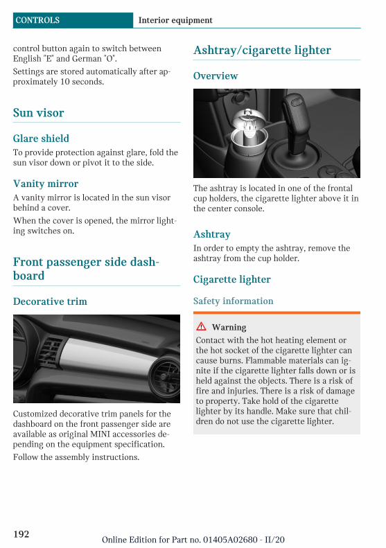
control button again to switch betweenEnglish "E" and German "O".
Settings are stored automatically after ap-proximately 10 seconds.
Sun visor
Glare shieldTo provide protection against glare, fold thesun visor down or pivot it to the side.
Vanity mirrorA vanity mirror is located in the sun visorbehind a cover.
When the cover is opened, the mirror light-ing switches on.
Front passenger side dash-board
Decorative trim
Customized decorative trim panels for thedashboard on the front passenger side areavailable as original MINI accessories de-pending on the equipment specification.
Follow the assembly instructions.
Ashtray/cigarette lighter
Overview
The ashtray is located in one of the frontalcup holders, the cigarette lighter above it inthe center console.
AshtrayIn order to empty the ashtray, remove theashtray from the cup holder.
Cigarette lighter
Safety information
Warning
Contact with the hot heating element orthe hot socket of the cigarette lighter cancause burns. Flammable materials can ig-nite if the cigarette lighter falls down or isheld against the objects. There is a risk offire and injuries. There is a risk of damageto property. Take hold of the cigarettelighter by its handle. Make sure that chil-dren do not use the cigarette lighter.
Seite 192
CONTROLS Interior equipment
192Online Edition for Part no. 01405A02680 - II/20

NOTICE
If metal objects fall into the socket, theycan cause a short circuit. There is a risk ofdamage to property. Replace the cigarettelighter or socket cover again after usingthe socket.
Operation
Push in the cigarette lighter.
The cigarette lighter can beremoved as soon as it popsback out.
Sockets
ConceptThe lighter socket can be used as a socketfor electrical equipment when standby anddrive-ready state are switched on.
General informationThe total load of all sockets must not exceed140 watts at 12 volts.
Do not damage the socket by using non-compatible connectors.
Safety information
Warning
Devices and cables in the unfolding area ofthe airbags, such as portable navigationdevices, can hinder the unfolding of theairbag or be thrown around in the car's in-terior during unfolding. There is a risk ofinjury. Make sure that devices and cablesare not in the airbag's area of unfolding.
NOTICE
Battery chargers for the vehicle batterycan work with high voltages and currents,which means that the 12 volt on-boardnetwork can be overloaded or damaged.There is a risk of damage to property. Onlyconnect battery chargers for the vehiclebattery to the starting aid terminals in theengine compartment.
NOTICE
If metal objects fall into the socket, theycan cause a short circuit. There is a risk ofdamage to property. Replace the cigarettelighter or socket cover again after usingthe socket.
In the center console
Remove the cover or cigarette lighter.
Seite 193
Interior equipment CONTROLS
193Online Edition for Part no. 01405A02680 - II/20

In the cargo area
The socket is located on the right side inthe cargo area.
USB port
General informationFollow the information regarding the con-nection of mobile devices to the USB port inthe section on USB connections, refer topage 55.
In the center console
Depending on the equipment version, a USBport Type A or a USB port Type A and a USBport Type C are located in the front of thecenter console.
Properties of upper USB port:
– USB port Type A.
– For charging mobile devices and fordata transfer.
– Charge current: max. 1.5 A.
Properties of lower USB port:
– USB port Type C.
– For charging mobile devices and fordata transfer.
– Charge current: max. 3 A.
Wireless charging tray
ConceptThe wireless charging tray enables the fol-lowing functions to be performed withoutcables:
– Charging the rechargeable battery of amobile phone with Qi capability and ofother mobile devices, which support theQi standard.
– Connect the mobile phone to the exter-nal antenna.
Depending on the country, this providesfor better network reception and a con-sistent reproduction quality.
General informationWhen inserting the mobile phone, makesure there are no objects between it and thewireless charging tray.
During charging, the surface of the tray andthe mobile phone may become warm.Higher temperatures may lead to a reduc-tion in the charge current through the mo-bile phone, and in isolated cases the charg-ing process is paused temporarily. Followthe relevant instructions in the mobilephone owner's manual.
NOTEThis device has been tested for human ex-posure limits and found compliant at a mini-mum distance of 4 in/10 cm during opera-tion.
Seite 194
CONTROLS Interior equipment
194Online Edition for Part no. 01405A02680 - II/20

Therefore, a distance of 4 in/10 cm must bemaintained in every direction when operat-ing the device.
Mounting position of the product.
Safety information
Warning
When charging a device that meets the Qistandard in the wireless charging tray, anymetal objects located between the deviceand the tray can become very hot. Placingstorage devices or electronic cards, suchas chip cards, cards with magnetic stripsor cards for signal transmission, betweenthe device and the tray may impair thecard function. There is a risk of injury andrisk of damage to property. When charg-ing mobile devices, make sure there are noobjects between the device and the tray.
NOTICE
The tray is intended for mobile phones upto a particular size. Forceful inserting ofthe mobile phone into the tray can damagethe tray or the mobile phone. There is arisk of damage to property. Observe themaximum dimensions for mobile phones.Do not force the mobile phone into thetray.
Functional requirements– Ignition or standby state is switched on.
– The mobile phone must compatibly sup-port the required Qi standard. Compati-ble mobile phones, refer to page 53.
If the mobile phone does not support theQi standard, the mobile phone can becharged using a special Qi-compatiblecharging case.
– Use only protective jackets and coversup to a maximum thickness of0.07 in/2 mm. Otherwise, the chargingfunction may be impaired.
– The mobile phone must not exceed themaximum size of approximately 5.9 x3.07 x 0.62 in/150 x 78 x 16 mm.
OverviewThe wireless charging tray is located in thecenter armrest.
1 Front holder with LED
2 Storage area
3 Movable clamp
Inserting the mobile phone1. Open center armrest, refer to vehicle
Owner's Manual.
2. Push back the clamp.
Seite 195
Interior equipment CONTROLS
195Online Edition for Part no. 01405A02680 - II/20

3. Insert the mobile phone with the displayfacing upward in the direction of thefront holder, arrow 1.
4. Place the mobile phone in the storagearea, arrow 2.
5. Push the clamp forward and clamp themobile phone in the tray.
6. Close the center armrest.
Removing the mobile phone1. Open the center armrest.
2. Push the clamp back and remove themobile phone.
LED displays
Color Meaning
Blue The mobile phone is charging.
Depending on the model, theblue LED is no longer illuminatedonce the inserted mobile phonewith Qi capability is fullycharged.
Or-ange
The mobile phone is not charg-ing.
Temperature on the mobilephone possibly too high or for-eign object in the charging tray.
Red The mobile phone is not charg-ing.
Contact a dealer’s service centeror another qualified service cen-ter or repair shop.
System limitsAt high temperatures on the mobile phoneor in the vehicle, the charging functions ofthe mobile phone may be limited and somefunctions may no longer work.
LTE-Compensator - Informationand User ManualYour car is equipped with a wireless charg-ing tray (WCA) to charge your mobile phoneand connect it to the mobile network. To en-sure the best possible connection a signalbooster (LTE-Compensator) is used in con-junction with the WCA. The following para-graphs refer to this booster:
This is a CONSUMER device.
BEFORE USE, you MUST REGISTER THISDEVICE with your wireless provider andhave your provider's consent. Most wirelessproviders consent to the use of Compensa-tors. Some providers may not consent to theuse of this device on their network. If you
Seite 196
CONTROLS Interior equipment
196Online Edition for Part no. 01405A02680 - II/20

are unsure, contact your provider. YouMUST operate this device with approved an-tennas and cables as specified by the manu-facturer. Antennas MUST be installed atleast 20 cm (8 inches) from any person. YouMUST cease operating this device immedi-ately if requested by the FCC or a licensedwireless service provider. Warning E911 lo-cation information may not be provided ormay be inaccurate for calls served by usingthis device.
Please observe additionally the following in-formation
– Sprint Nextel will allow consumers toregister their signal boosters by callingtheir toll-free number.
– T-Mobile online registration link:(www.T-Mobile.com/BoosterRegistra-tion); (https://saqat.t-mobile.com/sites/SignalBooster#).
– Verizon’s online registration link:(http://www.verizonwireless.com/wcms/consumer/register-signal-boos-ter.html).
– AT&T online registration link (https://securec45.securewebsession.com/attsignalbooster.com/).
– U.S.Cellular online registration link(http://www.uscellular.com/uscellular/support/fcc-booster-registration.jsp).
Before use you must register your boosterdevice with your wireless provider.
If you should be requested by the FCC tocease operating your booster, you are notallowed to insert your mobile phone in thecharging tray anymore unless the booster ispermanently deactivated by your local MINIdealer.
You must not remove the booster from thecar nor use it with any other than the prein-stalled coupling device or antenna. Anymodification of the existing antenna or cou-pling device as well as the use of other an-
tennas or coupling devices will cause thecease of the booster´s operating license.
The booster device fulfills the network pro-tection standards as required by the FCC,such as intermodulation limits, oscillationdetection and gain limits.
Booster Manufacturer: Kathrein Automotive
Model Number: LTECOMPB0
Part Number: 6803145-01
FCC-ID: 2ACC7LTECOMPB0
Seite 197
Interior equipment CONTROLS
197Online Edition for Part no. 01405A02680 - II/20

Storage compartments
Vehicle features and options
This chapter describes all standard, country-specific and optional features offered withthe series. It also describes features andfunctions that are not necessarily availablein your vehicle, e.g., due to the selected op-tions or country versions. This also appliesto safety-related functions and systems.When using these functions and systems,the applicable laws and regulations must beobserved.
Safety information
Warning
Loose objects or devices with a cable con-nection to the vehicle, for instance mobilephones, can be thrown about the car's in-terior while driving, for instance in theevent of an accident, braking or evasivemaneuver. There is a risk of injury. Secureloose objects or devices with a cable con-nection to the vehicle in the car's interior.
NOTICE
Anti-slip pads such as anti-slip mats candamage the dashboard. There is a risk ofdamage to property. Do not use anti-slippads.
Overview
The following storage compartments areavailable in the car's interior:
– Glove compartment on the front passen-ger side.
– Compartments in the doors.
– Storage compartment in the center arm-rest.
– Storage compartment in front of the cupholders.
– Clothes hooks
– Storage tray in the center console.
– Pockets on the backrests of the frontseats.
Glove compartment
Safety information
Warning
Folded open, the glove compartment pro-trudes in the car's interior. Objects in theglove compartment can be thrown into thecar's interior while driving, for instance inthe event of an accident, braking or eva-sive maneuvers. There is a risk of injury.Always close the glove compartment im-mediately after using it.
Seite 198
CONTROLS Storage compartments
198Online Edition for Part no. 01405A02680 - II/20

Opening
Pull the handle.
The light in the glove compartmentswitches on.
ClosingFold up the cover.
Compartments in the doors
General informationThere are storage compartments in thedoors.
Safety information
Warning
Breakable objects, such as glass bottles orglasses, can break in the event of an acci-dent or a braking or evasive maneuver.Broken glass can be scattered in the car'sinterior. There is a risk of injury or risk ofdamage to property. Do not use any break-able objects while driving. Only stowbreakable objects in closed storage com-partments.
Center armrest
General informationThe center armrest contains a storage com-partment.
Opening
Press button, arrow 1, and open center arm-rest upward, arrow 2.
Adjusting the height
Press button, arrow 1, and swing centerarmrest upward or downward into the de-sired height, arrow 2.
Seite 199
Storage compartments CONTROLS
199Online Edition for Part no. 01405A02680 - II/20
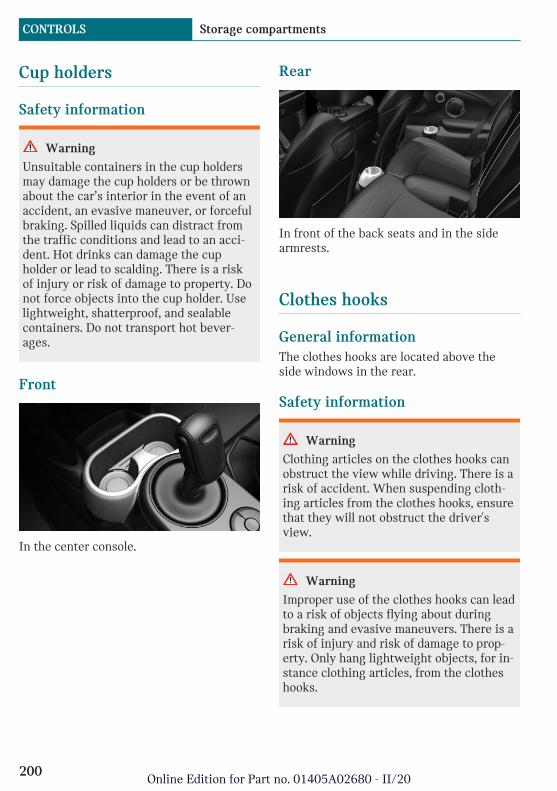
Cup holders
Safety information
Warning
Unsuitable containers in the cup holdersmay damage the cup holders or be thrownabout the car’s interior in the event of anaccident, an evasive maneuver, or forcefulbraking. Spilled liquids can distract fromthe traffic conditions and lead to an acci-dent. Hot drinks can damage the cupholder or lead to scalding. There is a riskof injury or risk of damage to property. Donot force objects into the cup holder. Uselightweight, shatterproof, and sealablecontainers. Do not transport hot bever-ages.
Front
In the center console.
Rear
In front of the back seats and in the sidearmrests.
Clothes hooks
General informationThe clothes hooks are located above theside windows in the rear.
Safety information
Warning
Clothing articles on the clothes hooks canobstruct the view while driving. There is arisk of accident. When suspending cloth-ing articles from the clothes hooks, ensurethat they will not obstruct the driver'sview.
Warning
Improper use of the clothes hooks can leadto a risk of objects flying about duringbraking and evasive maneuvers. There is arisk of injury and risk of damage to prop-erty. Only hang lightweight objects, for in-stance clothing articles, from the clotheshooks.
Seite 200
CONTROLS Storage compartments
200Online Edition for Part no. 01405A02680 - II/20
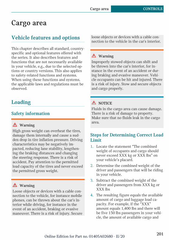
Cargo area
Vehicle features and options
This chapter describes all standard, country-specific and optional features offered withthe series. It also describes features andfunctions that are not necessarily availablein your vehicle, e.g., due to the selected op-tions or country versions. This also appliesto safety-related functions and systems.When using these functions and systems,the applicable laws and regulations must beobserved.
Loading
Safety information
Warning
High gross weight can overheat the tires,damage them internally and cause a sud-den drop in tire inflation pressure. Drivingcharacteristics may be negatively im-pacted, reducing lane stability, lengthen-ing the braking distances and changingthe steering response. There is a risk ofaccident. Pay attention to the permittedload capacity of the tires and never exceedthe permitted gross weight.
Warning
Loose objects or devices with a cable con-nection to the vehicle, for instance mobilephones, can be thrown about the car's in-terior while driving, for instance in theevent of an accident, braking or evasivemaneuver. There is a risk of injury. Secure
loose objects or devices with a cable con-nection to the vehicle in the car's interior.
Warning
Improperly stowed objects can shift andbe thrown into the car's interior, for in-stance in the event of an accident or dur-ing braking and evasive maneuver. Vehi-cle occupants can be hit and injured. Thereis a risk of injury. Stow and secure objectsand cargo properly.
NOTICE
Fluids in the cargo area can cause damage.There is a risk of damage to property.Make sure that no fluids leak in the cargoarea.
Steps for Determining Correct LoadLimit1. Locate the statement “The combined
weight of occupants and cargo shouldnever exceed XXX kg or XXX lbs” onyour vehicle’s placard.
2. Determine the combined weight of thedriver and passengers that will be ridingin your vehicle.
3. Subtract the combined weight of thedriver and passengers from XXX kg orXXX lbs
4. The resulting figure equals the availableamount of cargo and luggage load ca-pacity. For example, if the “XXX”amount equals 1,400 lbs and there willbe five 150 lbs passengers in your vehi-cle, the amount of available cargo and
Seite 201
Cargo area CONTROLS
201Online Edition for Part no. 01405A02680 - II/20

luggage load capacity is 650 lbs (1,400 -750 (5 x 150) = 650 lbs)
5. Determine the combined weight of lug-gage and cargo being loaded on the ve-hicle. That weight may not safely exceedthe available cargo and luggage load ca-pacity calculated in Step 4.
6. If your vehicle will be towing a trailer,load from your trailer will be transferredto your vehicle. Consult this manual todetermine how this reduces the availa-ble cargo and luggage load capacity ofyour vehicle.
Load
The maximum load is the sum of the weightof the occupants and the cargo.
The greater the weight of the occupants,the less cargo that can be transported.
Stowing and securing cargo– Cover sharp edges and corners on the
cargo.
– Heavy cargo: stow as far forward as pos-sible, directly behind and at the bottomof the rear passenger seat backrests.
– Very heavy cargo: when the rear seat isnot occupied, secure each of the outersafety belts in the opposite buckle.
– If necessary, fold down the rear back-rests to stow large cargo.
– Do not stack cargo above the top edge ofthe backrests.
– Small and light cargo: secure withratchet straps or draw straps.
– Larger and heavy cargo: secure withcargo straps.
Lashing eyes in the cargo area
Without storage compartment package: tosecure the cargo there are two lashing eyes,arrow 1, in the cargo area.
With storage compartment package: to se-cure the cargo there are six lashing eyes, ar-rows 1 and 2, in the cargo area.
Attach load securing aids, such as lashingstraps, tensioning straps, draw straps orcargo nets, to the lashing eyes in the cargoarea.
Cargo cover
General informationWhen the tailgate is opened, the cargocover is raised.
Seite 202
CONTROLS Cargo area
202Online Edition for Part no. 01405A02680 - II/20
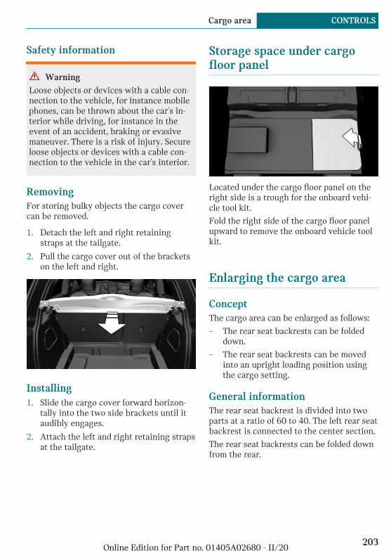
Safety information
Warning
Loose objects or devices with a cable con-nection to the vehicle, for instance mobilephones, can be thrown about the car's in-terior while driving, for instance in theevent of an accident, braking or evasivemaneuver. There is a risk of injury. Secureloose objects or devices with a cable con-nection to the vehicle in the car's interior.
RemovingFor storing bulky objects the cargo covercan be removed.
1. Detach the left and right retainingstraps at the tailgate.
2. Pull the cargo cover out of the bracketson the left and right.
Installing1. Slide the cargo cover forward horizon-
tally into the two side brackets until itaudibly engages.
2. Attach the left and right retaining strapsat the tailgate.
Storage space under cargofloor panel
Located under the cargo floor panel on theright side is a trough for the onboard vehi-cle tool kit.
Fold the right side of the cargo floor panelupward to remove the onboard vehicle toolkit.
Enlarging the cargo area
ConceptThe cargo area can be enlarged as follows:
– The rear seat backrests can be foldeddown.
– The rear seat backrests can be movedinto an upright loading position usingthe cargo setting.
General informationThe rear seat backrest is divided into twoparts at a ratio of 60 to 40. The left rear seatbackrest is connected to the center section.
The rear seat backrests can be folded downfrom the rear.
Seite 203
Cargo area CONTROLS
203Online Edition for Part no. 01405A02680 - II/20

Safety information
Warning
Danger of jamming with folding down thebackrests. There is a risk of injury or riskof damage to property. Make sure that thearea of movement of the rear backrest andthe of the head restraint is clear prior tofolding down.
Warning
If a rear seat backrest is not locked, unse-cured cargo can be thrown about the car’sinterior; for instance, in the event of an ac-cident, braking or an evasive maneuver.There is a risk of injury. Make sure thatthe rear seat backrest is locked after fold-ing it back.
Warning
The stability of the child restraint systemis limited or compromised with incorrectseat adjustment or improper installation ofthe child seat. There is a risk of injuries ordanger to life. Make sure that the child re-straint system fits securely against thebackrest. If possible, adjust the backresttilt for all affected backrests and correctlyadjust the seats. Make sure that seats andbackrests are securely engaged or locked.If possible, adjust the height of the headrestraints or remove them.
Warning
Body parts can be jammed when movingthe head restraint. There is a risk of injury.Make sure that the area of movement isclear when moving the head restraint.
Folding down the rear seatbackrest from the rear1. Before the rear seat backrest is folded
down, hook the corresponding safetybelt into the belt buckle on the side.
2. Pull the lever up, arrow 1, and fold therear seat backrest forward, arrow 2.
Cargo position
ConceptThe rear seat backrests can be moved intoan upright loading position.
Adjusting1. Release the backrest, and tilt it forward.
2. Fold the frame up until it engages.
3. Fold back and engage the rear seatbackrest.
Folding back the backrestFold up the backrest and press it into thelatch. Make sure that the safety belt is not
Seite 204
CONTROLS Cargo area
204Online Edition for Part no. 01405A02680 - II/20

caught behind the backrest or in betweenthe backrest and the rear seats.
The red marking on the lever disappearscompletely.
Variable cargo area floor
ConceptWith the variable cargo area floor, the cargoarea can be configured corresponding totransport requirements.
General informationFollow instructions on securing cargo, referto page 201.
Removing the cargo floor panel
Grasp the cargo floor panel in the rear andfold slightly upward. Next, pull it backwardfrom the supports.
The cargo floor panel can be removed fromthe cargo area above the tail lights.
Lower position
– Larger objects can be transported.
– Space for smaller objects remains be-tween the fixed and variable cargo areafloor.
Folded up position
Safety information
Warning
Improper use of the variable cargo floorpanel can lead to a danger of objects flyingabout during braking and evasive maneu-vers. There is a risk of injury and risk ofdamage to property.
– Do not use the variable cargo floorpanel to separate the cargo area andcar's interior in the sense of a parti-tion net.
– Only use the variable cargo floorpanel in the folded-up position whenthe backrests are folded up andlocked.
– Fold down the variable cargo floorpanel before driving off.
– Always secure cargo against shifting,using straps, belts and lashing eyes,for instance.
Seite 205
Cargo area CONTROLS
205Online Edition for Part no. 01405A02680 - II/20
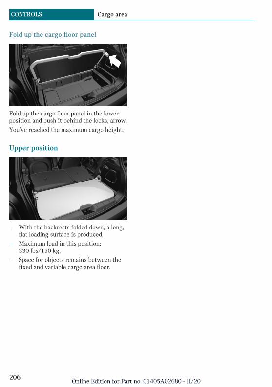
Fold up the cargo floor panel
Fold up the cargo floor panel in the lowerposition and push it behind the locks, arrow.
You've reached the maximum cargo height.
Upper position
– With the backrests folded down, a long,flat loading surface is produced.
– Maximum load in this position:330 lbs/150 kg.
– Space for objects remains between thefixed and variable cargo area floor.
Seite 206
CONTROLS Cargo area
206Online Edition for Part no. 01405A02680 - II/20

Seite 207
Cargo area CONTROLS
207Online Edition for Part no. 01405A02680 - II/20
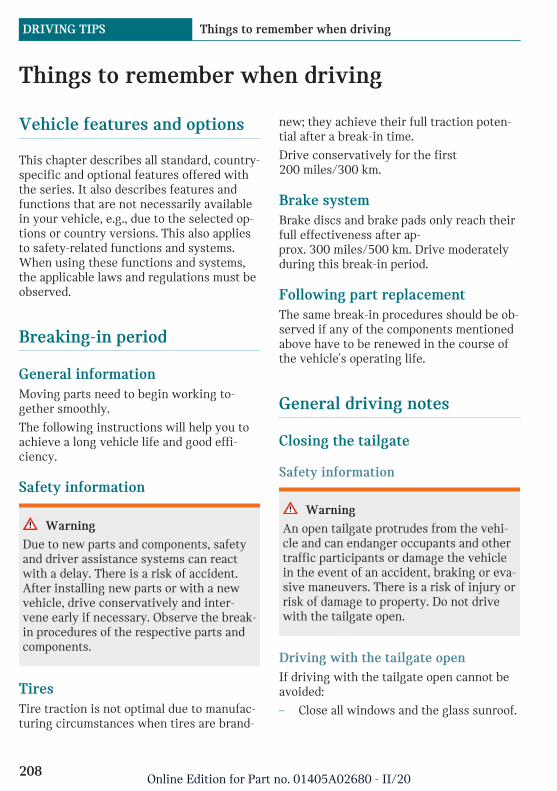
Things to remember when driving
Vehicle features and options
This chapter describes all standard, country-specific and optional features offered withthe series. It also describes features andfunctions that are not necessarily availablein your vehicle, e.g., due to the selected op-tions or country versions. This also appliesto safety-related functions and systems.When using these functions and systems,the applicable laws and regulations must beobserved.
Breaking-in period
General informationMoving parts need to begin working to-gether smoothly.
The following instructions will help you toachieve a long vehicle life and good effi-ciency.
Safety information
Warning
Due to new parts and components, safetyand driver assistance systems can reactwith a delay. There is a risk of accident.After installing new parts or with a newvehicle, drive conservatively and inter-vene early if necessary. Observe the break-in procedures of the respective parts andcomponents.
TiresTire traction is not optimal due to manufac-turing circumstances when tires are brand-
new; they achieve their full traction poten-tial after a break-in time.
Drive conservatively for the first200 miles/300 km.
Brake systemBrake discs and brake pads only reach theirfull effectiveness after ap-prox. 300 miles/500 km. Drive moderatelyduring this break-in period.
Following part replacementThe same break-in procedures should be ob-served if any of the components mentionedabove have to be renewed in the course ofthe vehicle's operating life.
General driving notes
Closing the tailgate
Safety information
Warning
An open tailgate protrudes from the vehi-cle and can endanger occupants and othertraffic participants or damage the vehiclein the event of an accident, braking or eva-sive maneuvers. There is a risk of injury orrisk of damage to property. Do not drivewith the tailgate open.
Driving with the tailgate openIf driving with the tailgate open cannot beavoided:
– Close all windows and the glass sunroof.
Seite 208
DRIVING TIPS Things to remember when driving
208Online Edition for Part no. 01405A02680 - II/20

– Greatly increase the air flow from thevents.
– Drive moderately.
Ice on window glass
NOTICE
The window will be lowered slightly whenpulling on the door handle. In the event offrost, the window may freeze up and notbe lowered. There is a risk of damage toproperty. When pulling on the door han-dle, make sure that the window is lowered.If necessary, remove snow and ice fromthe window. Do not open the door withforce.
Mobile communication devices inthe vehicle
Warning
Vehicle electronics and mobile phones caninfluence one another. There is radiationdue to the transmission operations of mo-bile phones. There is a risk of injury orrisk of damage to property. If possible, inthe car's interior use only mobile phoneswith direct connections to an exterior an-tenna in order to exclude mutual interfer-ence and deflect the radiation from thecar's interior.
HydroplaningOn wet or slushy roads, a wedge of watercan form between the tires and road sur-face.
This phenomenon is referred to as hydro-planing. It is characterized by a partial orcomplete loss of contact between the tiresand the road surface, ultimately undermin-
ing your ability to steer and brake the vehi-cle.
Driving through water
General informationWhen driving through water, follow the fol-lowing:
– Drive through calm water only.
– Drive through water only if it is notdeeper than maximum 9.8 inches/25 cm.
– Drive through water no faster thanwalking speed, up to 3 mph/5 km/h.
Safety information
NOTICE
When driving too quickly through toodeep water, water can enter into the en-gine compartment, the electrical system orthe transmission. There is a risk of damageto property. When driving through water,do not exceed the maximum indicated wa-ter level and the maximum speed for driv-ing through water.
Braking safely
General informationThe vehicle is equipped with an AntilockBraking System ABS as a standard feature.
Perform an emergency stop in situationsthat require such.
Steering is still responsive. You can stillavoid any obstacles with a minimum ofsteering effort.
Pulsation of the brake pedal and soundsfrom the hydraulic circuits indicate thatABS is in its active mode.
Seite 209
Things to remember when driving DRIVING TIPS
209Online Edition for Part no. 01405A02680 - II/20

Objects in the area around the pedals
Warning
Objects in the driver's floor area can limitthe pedal distance or block a depressedpedal. There is a risk of accident. Stow ob-jects in the vehicle such that they are se-cured and cannot enter into the driver'sfloor area. Use floor mats that are suitablefor the vehicle and can be safely attachedto the floor. Do not use loose floor matsand do not layer several floor mats. Makesure that there is sufficient clearance forthe pedals. Ensure that the floor mats aresecurely fastened again after they were re-moved, for instance for cleaning.
Driving in wet conditionsWhen roads are wet, salted, or in heavyrain, gently press the brake pedal every fewmiles.
Ensure that this action does not endangerother traffic.
The heat generated during braking driesbrake discs and brake pads and protectsthem against corrosion.
In this way braking efficiency will be avail-able when you need it.
Hills
General information
The braking effect of the drive system canbe influenced through the energy recovery.
Safety information
Warning
Light but consistent brake pressure canlead to high temperatures, brakes wearingout and possibly even brake failure. Thereis a risk of accident. Avoid placing exces-sive stress on the brake system.
Warning
In idle state or with drive-ready stateswitched off, safety-relevant functions, forinstance drive system braking effect, brak-ing force boost and steering assistance,are restricted or not available at all. Thereis a risk of accident. Do not drive in idlestate or with drive-ready state switchedoff.
Brake disc corrosionCorrosion on the brake discs and contami-nation on the brake pads are increased bythe following circumstances:
– Low mileage.
– Extended periods when the vehicle isnot used at all.
– Infrequent use of the brakes.
– Aggressive, acidic, or alkaline cleaningagents.
Corrosion buildup on the brake discs willcause a pulsating effect on the brakes intheir response - generally this cannot becorrected.
Condensation water under theparked vehicleWhen using the automatic climate control,condensation water develops and collectsunderneath the vehicle.
Seite 210
DRIVING TIPS Things to remember when driving
210Online Edition for Part no. 01405A02680 - II/20

Ground clearance
NOTICE
If the ground clearance is insufficient, e.g.,curbs or underground garage entrances,contact with vehicle parts, e.g., spoiler,and the underbody may occur. There is arisk of damage to property. Ensure thatthere is sufficient ground clearance availa-ble.
Roof-mounted luggage rack
General informationInstallation only possible with roof rack.
Roof racks are available as special accesso-ries.
MountingFollow the installation instructions of theroof rack.
LoadingBecause roof-mounted luggage racks raisethe vehicle's center of gravity when loaded,they have a major effect on vehicle handlingand steering response.
Therefore, note the following when loadingand driving:
– Do not exceed the approved roof/axleloads and the approved gross vehicleweight.
– Be sure that adequate clearance is main-tained for tilting and opening the glasssunroof.
– Distribute the roof load uniformly.
– The roof load should not extend past theloading area.
– Always place the heaviest pieces on thebottom.
– Secure the roof luggage firmly, for in-stance using ratchet straps.
– Do not let objects project into the open-ing path of the tailgate.
– Drive cautiously and avoid sudden ac-celeration and braking maneuvers. Takecorners gently.
Driving on racetracks
Warning
The vehicle is not designed for use in MSport or motor sport type competition.There is a risk of accident. Do not use thevehicle for M Sport or motor sport typecompetitions.
Higher mechanical and thermal loads duringracetrack operation lead to increased wear.This wear is not covered by the warranty.
Seite 211
Things to remember when driving DRIVING TIPS
211Online Edition for Part no. 01405A02680 - II/20
Increasing range
Vehicle features and options
This chapter describes all standard, country-specific and optional features offered withthe series. It also describes features andfunctions that are not necessarily availablein your vehicle, e.g., due to the selected op-tions or country versions. This also appliesto safety-related functions and systems.When using these functions and systems,the applicable laws and regulations must beobserved.
General information
The vehicle contains comprehensive tech-nologies for reducing energy consumptionand for maximizing the range.
The range depends on a number of differentfactors, refer to page 125.
The implementation of certain measures,driving style and regular maintenance canincreasing the range and thereby also re-duce the environmental impact.
Remove unnecessary cargo
Additional weight reduces the range.
Remove attached parts follow-ing use
Remove auxiliary mirrors, roof-mounted orrear luggage racks which are no longer re-quired following use.
Attached parts on the vehicle impair theaerodynamics and increase the energy con-sumption.
Close the windows and glasssunroof
Driving with the glass sunroof and windowsopen results in increased air resistance andthereby reduces the range.
Tires
General informationTires can affect energy consumption in vari-ous ways, for instance energy consumptioncan be influenced by tire size.
Check the tire inflation pressureregularlyCheck and, if needed, correct the tire infla-tion pressure at least twice a month and be-fore starting on a long trip.
Low tire inflation pressure increases rollingresistance and thus raises energy consump-tion and tire wear.
Stationary climate control
Run advance climate control, refer topage 184, in the vehicle during charging be-fore driving off.
Heating and cooling operations are very en-ergy intensive and substantially reduce theelectric range.
Seite 212
DRIVING TIPS Increasing range
212Online Edition for Part no. 01405A02680 - II/20
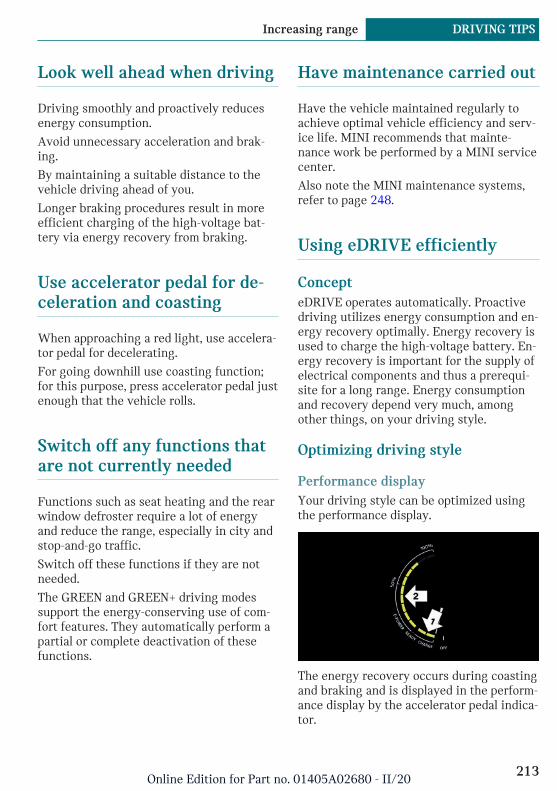
Look well ahead when driving
Driving smoothly and proactively reducesenergy consumption.
Avoid unnecessary acceleration and brak-ing.
By maintaining a suitable distance to thevehicle driving ahead of you.
Longer braking procedures result in moreefficient charging of the high-voltage bat-tery via energy recovery from braking.
Use accelerator pedal for de-celeration and coasting
When approaching a red light, use accelera-tor pedal for decelerating.
For going downhill use coasting function;for this purpose, press accelerator pedal justenough that the vehicle rolls.
Switch off any functions thatare not currently needed
Functions such as seat heating and the rearwindow defroster require a lot of energyand reduce the range, especially in city andstop-and-go traffic.
Switch off these functions if they are notneeded.
The GREEN and GREEN+ driving modessupport the energy-conserving use of com-fort features. They automatically perform apartial or complete deactivation of thesefunctions.
Have maintenance carried out
Have the vehicle maintained regularly toachieve optimal vehicle efficiency and serv-ice life. MINI recommends that mainte-nance work be performed by a MINI servicecenter.
Also note the MINI maintenance systems,refer to page 248.
Using eDRIVE efficiently
ConcepteDRIVE operates automatically. Proactivedriving utilizes energy consumption and en-ergy recovery optimally. Energy recovery isused to charge the high-voltage battery. En-ergy recovery is important for the supply ofelectrical components and thus a prerequi-site for a long range. Energy consumptionand recovery depend very much, amongother things, on your driving style.
Optimizing driving style
Performance displayYour driving style can be optimized usingthe performance display.
The energy recovery occurs during coastingand braking and is displayed in the perform-ance display by the accelerator pedal indica-tor.
Seite 213
Increasing range DRIVING TIPS
213Online Edition for Part no. 01405A02680 - II/20
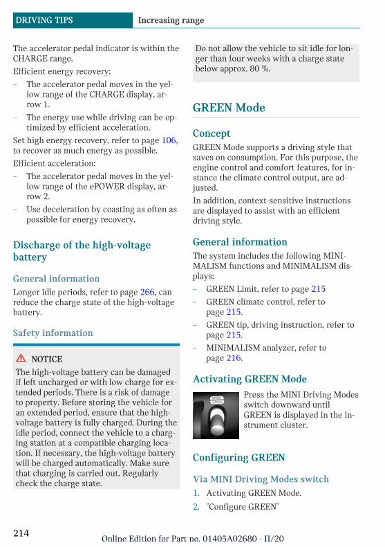
The accelerator pedal indicator is within theCHARGE range.
Efficient energy recovery:
– The accelerator pedal moves in the yel-low range of the CHARGE display, ar-row 1.
– The energy use while driving can be op-timized by efficient acceleration.
Set high energy recovery, refer to page 106,to recover as much energy as possible.
Efficient acceleration:
– The accelerator pedal moves in the yel-low range of the ePOWER display, ar-row 2.
– Use deceleration by coasting as often aspossible for energy recovery.
Discharge of the high-voltagebattery
General informationLonger idle periods, refer to page 266, canreduce the charge state of the high-voltagebattery.
Safety information
NOTICE
The high-voltage battery can be damagedif left uncharged or with low charge for ex-tended periods. There is a risk of damageto property. Before storing the vehicle foran extended period, ensure that the high-voltage battery is fully charged. During theidle period, connect the vehicle to a charg-ing station at a compatible charging loca-tion. If necessary, the high-voltage batterywill be charged automatically. Make surethat charging is carried out. Regularlycheck the charge state.
Do not allow the vehicle to sit idle for lon-ger than four weeks with a charge statebelow approx. 80 %.
GREEN Mode
ConceptGREEN Mode supports a driving style thatsaves on consumption. For this purpose, theengine control and comfort features, for in-stance the climate control output, are ad-justed.
In addition, context-sensitive instructionsare displayed to assist with an efficientdriving style.
General informationThe system includes the following MINI-MALISM functions and MINIMALISM dis-plays:
– GREEN Limit, refer to page 215
– GREEN climate control, refer topage 215.
– GREEN tip, driving instruction, refer topage 215.
– MINIMALISM analyzer, refer topage 216.
Activating GREEN ModePress the MINI Driving Modesswitch downward untilGREEN is displayed in the in-strument cluster.
Configuring GREEN
Via MINI Driving Modes switch1. Activating GREEN Mode.
2. "Configure GREEN"
Seite 214
DRIVING TIPS Increasing range
214Online Edition for Part no. 01405A02680 - II/20

3. Select the desired setting.
Via the Central Information Display(CID)1. "My MINI"
2. "Vehicle settings"
3. "Configure GREEN"
4. Select the desired setting.
Activating/deactivating the functionsThe following functions can be activated/deactivated:
– "GREEN speed warning"
– "GREEN climate control"
– "Coasting"
Settings are stored for the driver profilecurrently used.
GREEN Limit– "GREEN speed warning": GREEN Limit
is activated.
A GREEN tip is displayed if the speed ofthe set GREEN Limit is exceeded.
– "Tip at:"
Set the desired speed for the GREENLimit.
When GREEN+ is activated, the GREENLimit is set to 55 mph/90 km/h.
GREEN climate controlClimate control is set to be efficient.
By making a slight change to the set tem-perature and adjusting the rate of heatingor cooling of the car's interior consumptioncan be economized.
The power output to the seat heater and ex-terior mirror is reduced.
GREEN potential savingsShows potential savings with the currentsettings in percentages.
Display in the instrument cluster
GREEN tip, driving instruction
General information
The GREEN tip indicates that your drivingstyle can be modified to be more efficient,for example by backing off the accelerator.
Activating/deactivating the displayActivate information relating to the drivingstyle and GREEN tips in the instrumentcluster using the Central Information Dis-play (CID):
1. "My MINI"
2. "System settings"
3. "Displays"
4. "Instrument panel"
5. "GREEN info"
GREEN tip, symbolsAn additional symbol and text instructionsare displayed.
Symbol Measure
For an efficient driving style,look well ahead when driving,accelerate conservatively, anddelay accelerating.
Reduce speed to the selectedGREEN speed.
Seite 215
Increasing range DRIVING TIPS
215Online Edition for Part no. 01405A02680 - II/20

Indications on the Control Display
Displaying MINIMALISM informationThe current efficiency of the functions inGREEN Mode can be displayed on the Con-trol Display.
Via the Central Information Display (CID):
1. "My MINI"
2. "Technology in action"
3. "MINIMALISM"
Information is shown on the following func-tions:
– Auto Start/Stop function.
– Energy recovery.
MINIMALISM analyzer
ConceptIn this situation, the function helps developan especially efficient driving style and tosave energy.
For this purpose, the driving style is ana-lyzed. The assessment is done in variouscategories and is displayed on the ControlDisplay.
This display will help you adjust your driv-ing style and save some energy.
Functional requirementThis function is available in GREEN Mode.
Displaying the MINIMALISM analyzerVia the Central Information Display (CID):
1. "My MINI"
2. "Technology in action"
3. "MINIMALISM Analyser"
Display on the Control DisplayThe display of the MINIMALISM analyzerconsists of a fish in a water glass and avalue table.
The fish and the movements of the water inthe bowl symbolize the efficiency of thedriving style.
Depending on the equipment, the fish isshown with efficient and inefficient drivingstyle or only with inefficient driving style.
The more efficient the driving style, the lessthe water sloshes around in the bowl andthe better is the fish's mood. If the drivingstyle is inefficient, the water oscillates, thefish's mood worsens, and a reduced numberof stars is displayed.
The table of values contains stars and evalu-ates the driving style in different catego-ries. The more efficient the driving style,the more stars are displayed in the table.
To assist with an efficient driving style,GREEN tips are displayed while driving.
Tips for an energy-saving driving style, In-creasing the range, refer to page 212.
Seite 216
DRIVING TIPS Increasing range
216Online Edition for Part no. 01405A02680 - II/20

Seite 217
Increasing range DRIVING TIPS
217Online Edition for Part no. 01405A02680 - II/20
Charging the vehicle
Vehicle features and options
This chapter describes all standard, country-specific and optional features offered withthe series. It also describes features andfunctions that are not necessarily availablein your vehicle, e.g., due to the selected op-tions or country versions. This also appliesto safety-related functions and systems.When using these functions and systems,the applicable laws and regulations must beobserved.
Concept
The vehicle can be charged using variouscharging cables at charging stations orhousehold sockets. Control and monitoringof the charging process are handled com-pletely automatically. The charge currentstrength can be set via the Central Informa-tion Display (CID).
General information
High-voltage batteryThe high-voltage battery is used as an en-ergy accumulator. The high-voltage batterycan be charged by energy recovery duringthe trip or via the power grid.
In order to operate the high-voltage batteryoptimally, charge the vehicle regularly andfully using a compatible charger.
When charging via the power grid, you canchose between the following variants.
– Level 1 charging via a household socket.
– Level 2 charging via a Level 2 chargingstation.
– Charging via a DC charging station.
Level 1 charging is possible via a householdsocket with a voltage of 120 volts.
For optimal use of the energy from thepower mains, charging at a charging sta-tion, for instance BMW Wallbox, is recom-mended.
Charge current
General informationThe charge current strength is indicated inamperes.
The vehicle cannot automatically detect themaximum permissible charge currentstrength of the power grid during chargingvia a household socket or charging station.
Level 1 chargingPrior to the first Level 1 charging at yourown household socket, or at other house-hold sockets, the permitted charge currentstrength must be determined by a qualifiedelectrician, for example.
The charge current strength forLevel 1 charging, refer to page 224, can beadjusted in the vehicle in three levels.
At delivery, the charge current forLevel 1 charging is set to the lowest level.
Depending on the country-specific version,one of several ampere ratings is printed onthe Level 1 charging cable. This ampere rat-ing is the limit which must be adhered tofor the vehicle if the charge current is set tothe highest level. Depending on the charg-ing cable, the charge current strength mayvary when lower levels are set.
Seite 218
MOBILITY Charging the vehicle
218Online Edition for Part no. 01405A02680 - II/20
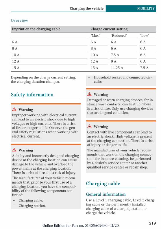
Overview
Imprint on the charging cable Charge current setting
"Max." "Reduced" "Low"
6 A 6 A 6 A 6 A
8 A 8 A 6 A 6 A
10 A 10 A 7.5 A 6 A
12 A 12 A 9 A 6 A
15 A 15 A 11.25 A 7.5 A
Depending on the charge current setting,the charging duration changes.
Safety information
Warning
Improper working with electrical currentcan lead to an electric shock due to highvoltages or high currents. There is a riskof fire or danger to life. Observe the gen-eral safety regulations when working withelectrical current.
Warning
A faulty and incorrectly designed chargingdevice at the charging location can causedamage to the vehicle and overload thepower mains at the charging location.There is a risk of fire and a risk of injury.
The manufacturer of your vehicle recom-mends that, prior to your first use of acharging location, you have the compati-bility of the following components con-firmed:
– Charging cable.
– Charging station.
– Household socket and connected cir-cuits.
Warning
Damaged or worn charging devices, for in-stance worn contacts, can heat up. Thereis a risk of fire. Only use charging devicesthat are in good condition.
Warning
Contact with live components can lead toan electric shock. High voltage is presentat the charging connection. There is a riskof injury or danger to life.
The manufacturer of your vehicle recom-mends that work on the charging connec-tion, for instance cleaning, be performedby a dealer’s service center or anotherqualified service center or repair shop.
Charging cable
General informationUse a Level 1 charging cable, Level 2 charg-ing cable or the permanently installedcharging cable of a charging station tocharge the vehicle.
Seite 219
Charging the vehicle MOBILITY
219Online Edition for Part no. 01405A02680 - II/20
Different charging cables can be requireddepending on the country.
Safety information
Warning
Non-compatible charging cables or unsuit-able charging stations can heat up andcause damage to the vehicle. There is arisk of fire. Use charging cables or charg-ing stations for charging that are suitablefor the respective vehicle type.
A dealer's service center will be glad toprovide information about suitable charg-ing cables.
Warning
Improper use of the charging cable canprevent charging and lead to damage, forinstance cable fire. There is a risk of fire.Use the charging cable only for chargingthe vehicle, and do not extend it using ca-bles or adapters.
Warning
Damaged charging cables can heat up orlead to an electric shock. There is a risk offire or a risk of injury. Use undamagedcharging cables only.
Level 1 charging cableThe vehicle is supplied with aLevel 1 charging cable.
Level 1 charging cables can be used tocharge the vehicle from grounded house-hold sockets. Charging at household socketconnections is performed with alternatingcurrent.
When a Level 1 charging cable is used, theefficiency values may differ from thosestated on the energy label.
Level 2 charging cableThe Level 2 charging cable makes it possi-ble to quickly recharge at sockets of desig-nated Level 2 charging stations using a spe-cial plug. Charging is performed withalternating current at designatedLevel 2 charging stations. The chargingprocess can be completed faster than athousehold sockets.
A charge current strength of up to maxi-mum 16 A is possible.
The charging cable may be permanently in-stalled at the charging station.
DC charging cableThe DC charging cable that is permanentlyinstalled at the charging station makes ispossible to charge at DC charging stations.Charging is performed with direct currentat designated DC charging stations. At thehigher capacity current connection of a DCcharger station the charging time is signifi-cantly lower than with a household socketor a Level 2 charging station.
During charging at a DC charging station,an indication in the instrument cluster, re-fer to page 225, is displayed.
The DC charging cable is also referred to asLevel 3 DC charging cable.
Seite 220
MOBILITY Charging the vehicle
220Online Edition for Part no. 01405A02680 - II/20

Storage
The Level 1 charging cable is located in abag in the cargo area.
Store charging cable again in the bag afteruse. Attach the bag to the designated eyelet.
If required, store the charging cable withthe installed plug cover to prevent moisturein the charging cable plug.
Connecting
Charging socket flap
The charging socket flap is located on theright side of the vehicle.
Always keep charging socket clean and un-obstructed.
Keep the charging socket flap closed whenthe charging socket is not used.
Connecting the charging cableTo connect, engage selector lever posi-tion P, deactivate drive-ready state, and un-
lock the vehicle. Set the parking brake, ifneeded.
1. Tap on the charging socket flap, arrow.The charging socket flap opens.
2. Remove the charging socket lid, arrow.
3. Remove the cover of the charging cableplug, if needed.
4. Connect Level 1 charging cable to thehousehold socket or Level 2 chargingcable to the port on the charging station.
5. Insert the appropriate charging cableplug, and push it in until it engages.
When charging at a charging station, followthe instructions at the charging station.
RemovingWhen the charging process is active andthe vehicle is locked, the charging cable isautomatically locked. Unlock the vehicle be-fore removing the cable.
When the charging process is completed,the charging cable is automatically un-locked.
Seite 221
Charging the vehicle MOBILITY
221Online Edition for Part no. 01405A02680 - II/20
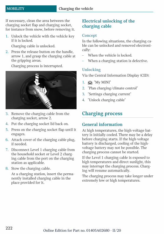
If necessary, clean the area between thecharging socket flap and charging socket,for instance from snow, before removing it.
1. Unlock the vehicle with the vehicle keyif it is locked.
Charging cable is unlocked.
2. Press the release button on the handle,arrow 1, and grasp the charging cable atthe gripping areas.
Charging process is interrupted.
3. Remove the charging cable from thecharging socket, arrow 2.
4. Put the charging socket lid back on.
5. Press on the charging socket flap until itengages.
6. Attach cover of the charging cable plug,if needed.
7. Disconnect Level 1 charging cable fromthe household socket or Level 2 charg-ing cable from the port on the chargingstation as applicable.
8. Stow the charging cable.
At a charging station, insert the perma-nently installed charging cable in theplace provided for it.
Electrical unlocking of thecharging cable
ConceptIn the following situations, the charging ca-ble can be unlocked and removed electroni-cally:
– When the vehicle is locked.
– When a charging station is defective.
UnlockingVia the Central Information Display (CID):
1. "My MINI"
2. "Plan charging/climate control"
3. "Settings charging current"
4. "Unlock charging cable"
Charging process
General informationAt high temperatures, the high-voltage bat-tery is initially cooled. There may be a delaybefore charging starts. If the high-voltagebattery is discharged, cooling of the high-voltage battery may not be possible. Thecharging process cannot be started.
If the Level 1 charging cable is exposed tohigh temperatures and direct sunlight, thismay interrupt the charging process. Charg-ing will resume automatically.
The charging process may take longer underextremely low or high temperatures.
Seite 222
MOBILITY Charging the vehicle
222Online Edition for Part no. 01405A02680 - II/20
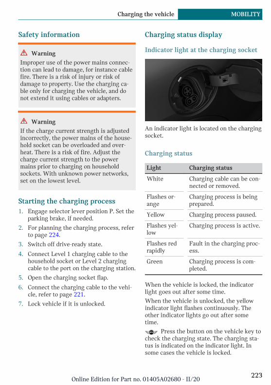
Safety information
Warning
Improper use of the power mains connec-tion can lead to damage, for instance cablefire. There is a risk of injury or risk ofdamage to property. Use the charging ca-ble only for charging the vehicle, and donot extend it using cables or adapters.
Warning
If the charge current strength is adjustedincorrectly, the power mains of the house-hold socket can be overloaded and over-heat. There is a risk of fire. Adjust thecharge current strength to the powermains prior to charging on householdsockets. With unknown power networks,set on the lowest level.
Starting the charging process1. Engage selector lever position P. Set the
parking brake, if needed.
2. For planning the charging process, referto page 224.
3. Switch off drive-ready state.
4. Connect Level 1 charging cable to thehousehold socket or Level 2 chargingcable to the port on the charging station.
5. Open the charging socket flap.
6. Connect the charging cable to the vehi-cle, refer to page 221.
7. Lock vehicle if it is unlocked.
Charging status display
Indicator light at the charging socket
An indicator light is located on the chargingsocket.
Charging status
Light Charging status
White Charging cable can be con-nected or removed.
Flashes or-ange
Charging process is beingprepared.
Yellow Charging process paused.
Flashes yel-low
Charging process is active.
Flashes redrapidly
Fault in the charging proc-ess.
Green Charging process is com-pleted.
When the vehicle is locked, the indicatorlight goes out after some time.
When the vehicle is unlocked, the yellowindicator light flashes continuously. Theother indicator lights go out after sometime.
Press the button on the vehicle key tocheck the charging state. The charging sta-tus is indicated on the indicator light. Insome cases the vehicle is locked.
Seite 223
Charging the vehicle MOBILITY
223Online Edition for Part no. 01405A02680 - II/20

Additional messages about the charging sta-tus, for instance the probable end of charg-ing or the planned departure time, can beshown in the instrument cluster or on theControl Display.
Planning the charging process
General informationThe charging process can be adapted toconstraints, for instance the cost of electric-ity. The vehicle controls the charging proc-ess in such a way that the charging processis completed if possible at the departuretime. A departure time must be set for thispurpose, refer to page 225.
The following settings are available:
– Immediate charging.
– Set time window for favorable charging.
– Set the charge current for charging via aLevel 1 charging cable.
If drive-ready state is switched off, changescan be made via the Central InformationDisplay (CID). Settings for the stationary cli-mate control and charging process are alsoaccepted for planned departure times.
Setting the charging modeVia the Central Information Display (CID):
1. "My MINI"
2. "Plan charging/climate control"
3. Select the desired setting:
– "Charge immediately": the chargingprocess starts as soon as the charg-ing cable is connected.
– "Charge for departure time": if a de-parture time is set, a time windowfor charging with a favorable elec-tricity rate can be set.
Setting the time window for favorable-rateVia the Central Information Display (CID):
1. "My MINI"
2. "Plan charging/climate control"
3. "Set low cost time slot"
4. Set rate begin.
5. Set rate end.
The vehicle can also start the charging proc-ess before the selected time window beginsor end it after the selected time window fin-ishes. The starting point of the chargingprocess is adjusted so the vehicle can be asfully charged as possible and, if applicable,its climate adjusted by the departure time.
Setting the charge current forcharging via a Level 1 charging cableDepending on the electrical mains, the vehi-cle must be charged with a different chargecurrent strength, refer to page 218.
Via the Central Information Display (CID):
1. "My MINI"
2. "Plan charging/climate control"
3. "Settings charging current"
4. "Level 1 (120V)"
Settings are stored. When you changecharging locations you also might need tochange the setting for charging.
Set the charge current strength at otherhousehold sockets to the lowest level.
Stopping the charging processThe charging process can be stopped at anytime by removing the charging cable andcontinued at a later time by connecting thecharging cable. This enables, for instancethe use of other loads on the power connec-tion or prevents simultaneous high powerfrom multiple loads.
Seite 224
MOBILITY Charging the vehicle
224Online Edition for Part no. 01405A02680 - II/20

For removing the charging cable, refer topage 221.
Continuing the charging processIf the charging process is interrupted, forinstance through a temporary power failure,the charging process is automatically con-tinued after the interruption.
Terminating the charging process1. Remove the charging cable from the ve-
hicle, refer to page 221.
2. Stow the charging cable as required.
3. Close the charging socket flap.
4. Lock vehicle if it is unlocked.
Displays in the instrumentcluster
The charge state indicator light, refer topage 120, shows the charge state of thehigh-voltage battery in the instrument clus-ter, if the standby state or drive-ready stateis switched on. If all bars are filled, thehigh-voltage battery is fully charged.
Even if no bars are filled, the high-voltagesystem is still under high voltage.
Information regarding the charging processis shown on the charging screen.
Display Meaning
Ring orange: the charging proc-ess is being prepared.
Ring yellow animated: thecharging process is active or itwill start at the set time.
Ring yellow: the charging proc-ess pauses.
Ring red: fault in the chargingprocess.
Ring green: the charging proc-ess is completed.
End of charging time or set de-parture time.
DC charging active on a DCcharging station.
Departure time set.
Climate control activated at de-parture time.
Flashing: ventilation active.
Flashing: heating active.
Flashing: cooling active.
Departure time
ConceptFor optimum range and climate control, thedeparture time can be set before parkingthe vehicle.
Seite 225
Charging the vehicle MOBILITY
225Online Edition for Part no. 01405A02680 - II/20
General informationWith a set departure time, the vehicle ispreheated or precooled during the chargingprocess if climate control is set. Climatecontrol output is reduced during the trip.This increases the range during electricdriving.
The following settings are possible for de-parture time:
– Climate control for departure time.
– Planning of up to two regular departuretimes.
If drive-ready state is switched off, changescan be made via the Central InformationDisplay (CID). Settings for climate controland charging process are also applied forscheduled departure times.
Climate control for departure timeVia the Central Information Display (CID):
1. "My MINI"
2. "Plan charging/climate control"
3. "Precondition for departure"
Setting the departure timeVia the Central Information Display (CID):
1. "My MINI"
2. "Plan charging/climate control"
3. "Set departure time"
4. Set the desired days of the week, ifneeded.
5. Set the desired time.
Up to three departure times can be set.
Activating the departure timeVia the Central Information Display (CID):
1. "My MINI"
2. "Plan charging/climate control"
3. "Set departure time"
Set departure times are displayed.
4. For example activate "Departure time 1".
Up to two departure times can be activated.
The set departure time will be deactivated,if the departure time was ignored threetimes in a row.
Climate control
The following settings for vehicle air condi-tioning are possible:
– Activate stationary climate control im-mediately, refer to page 184.
The range is reduced if stationary cli-mate control is activated without acharging cable connected.
– Planned climate control at the set depar-ture time, refer to page 185.
If a Mode 2 charging cable is used, thehigh-voltage battery may not be fullycharged at departure time.
Discharged high-voltage andvehicle battery
General informationIn addition to the high-voltage battery, thevehicle has a 12 volt vehicle battery, whichis required for operation of the onboardelectronics.
With a discharged vehicle battery, no oper-ation of the vehicle is possible.
Seite 226
MOBILITY Charging the vehicle
226Online Edition for Part no. 01405A02680 - II/20

Wheels and tires
Vehicle features and options
This chapter describes all standard, country-specific and optional features offered withthe series. It also describes features andfunctions that are not necessarily availablein your vehicle, e.g., due to the selected op-tions or country versions. This also appliesto safety-related functions and systems.When using these functions and systems,the applicable laws and regulations must beobserved.
Tire inflation pressure
General informationThe tire characteristics and tire inflationpressure influence the following:
– The service life of the tires.
– Road safety.
– Driving comfort.
– Fuel consumption.
Safety information
Warning
A tire with too little or no tire inflationpressure may heat up significantly andsustain damage. This will have a negativeimpact on aspects of handling, such assteering and braking response. There is arisk of accident. Regularly check the tireinflation pressure, and correct it asneeded, for instance twice a month and be-fore a long trip.
Tire inflation pressurespecifications
In the tire inflation pressure tableThe tire inflation pressure table, refer topage 228, contains all tire inflation pres-sure specifications for the specified tiresizes at the ambient temperature. The tireinflation pressure values apply to tire sizesapproved by the manufacturer of the vehiclefor the vehicle type.
To identify the correct tire inflation pres-sure, please note the following:
– Tire sizes of your vehicle.
– Maximum permitted driving speed.
Checking the tire inflation pressure
General informationTires heat up while driving. The tire infla-tion pressure increases with the tire tem-perature.
Tires have a natural, consistent loss of tireinflation pressure.
The displays of inflation devices may under-read by up to 0.1 bar/2 psi.
Checking using tire inflation pressurespecifications in the tire inflationpressure tableThe tire inflation pressure specifications inthe tire inflation pressure table only relateto cold tires or tires at the same tempera-ture as the ambient temperature.
Only check the tire inflation pressure levelswhen the tires are cold, i.e.:
– Driving range of max. 1.25 miles/2 kmhas not been exceeded.
Seite 227
Wheels and tires MOBILITY
227Online Edition for Part no. 01405A02680 - II/20
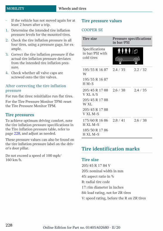
– If the vehicle has not moved again for atleast 2 hours after a trip.
1. Determine the intended tire inflationpressure levels for the mounted tires.
2. Check the tire inflation pressure in allfour tires, using a pressure gage, for ex-ample.
3. Correct the tire inflation pressure if theactual tire inflation pressure deviatesfrom the intended tire inflation pres-sure.
4. Check whether all valve caps arescrewed onto the tire valves.
After correcting the tire inflationpressureFor run-flat tires: reinitialize run-flat tires.
For the Tire Pressure Monitor TPM: resetthe Tire Pressure Monitor TPM.
Tire pressuresTo achieve optimum driving comfort, notethe tire inflation pressure specifications inthe Tire inflation pressure table, refer topage 228, and adjust as needed.
These pressure values can also be found onthe tire inflation pressure label on the driv-er's door pillar.
Do not exceed a speed of 100 mph/160 km/h.
Tire pressure values
COOPER SE
Tire size Pressure specificationsin bar/PSI
Specificationsin bar/PSI withcold tires
195/55 R 16 87W
195/55 R 16 87H M+S
2.4 / 35 2.2 / 32
205/45 R 17 88V XL A/S
205/45 R 17 88W XL
205/45 R 17 88V XL M+S
2.6 / 38 2.4 / 35
175/60 R 16 86H XL M+S
185/50 R 17 86H XL M+S
2.8 / 41 2.6 / 38
Tire identification marks
Tire size205/45 R 17 84 V
205: nominal width in mm
45: aspect ratio in %
R: radial tire code
17: rim diameter in inches
84: load rating, not for ZR tires
V: speed rating, before the R on ZR tires
Seite 228
MOBILITY Wheels and tires
228Online Edition for Part no. 01405A02680 - II/20

Maximum tire loadMaximum tire load is the maximum permis-sible weight for which the tire is approved.
Locate the maximum tire load on the tiresidewall and the Gross Axle Weight Rating– GAWR – on the certification label on thedriver’s door pillar. Divide the tire load by1.1. It must be greater than one-half of thevehicle’s Gross Axle Weight Rating –GAWR. Note, front vs. rear GAWR and tireloads, respectively.
Speed letter
Designation Maximum speed
Q up to 100 mph/160 km/h
R: up to 106 mph/170 km/h
S up to 112 mph/180 km/h
T up to 118 mph/190 km/h
H up to 131 mph/210 km/h
V up to 150 mph/240 km/h
W up to 167 mph/270 km/h
Y up to 186 mph/300 km/h
Tire Identification NumberDOT-Code: DOT xxxx xxx 0120
xxxx: manufacturer code for the tire brand
xxx: tire size and tire design
0120: tire age
Tires with DOT codes meet the guidelinesof the U.S. Department of Transportation.
Tire age
RecommendationRegardless of the tire tread, replace tires atleast every 6 years.
Manufacture dateYou can find the manufacture date of thetire on the tire's sidewall.
Designation Manufacture date
DOT … 0120 1st week 2020
Uniform Tire Quality GradingQuality grades can be found where applica-ble on the tire sidewall between treadshoulder and maximum section width.
E.g.: Treadwear 200; Traction AA; Tempera-ture A
DOT Quality GradesTreadwear
Traction AA A B C
Temperature A B C
All passenger vehicle tires must conform toFederal Safety Requirements in addition tothese grades.
TreadwearThe treadwear grade is a comparative ratingbased on the wear rate of the tire whentested under controlled conditions on aspecified government test course. E.g., atire graded 150 would wear one and one-half, 1 g, times as well on the governmentcourse as a tire graded 100. The relativeperformance of tires depends upon the ac-tual conditions of their use, however, andmay depart significantly from the norm dueto variations in driving habits, service prac-tices and differences in road characteristicsand climate.
TractionThe traction grades, from highest to lowest,are AA, A, B, and C.
Those grades represent the tire's ability tostop on wet pavement as measured under
Seite 229
Wheels and tires MOBILITY
229Online Edition for Part no. 01405A02680 - II/20
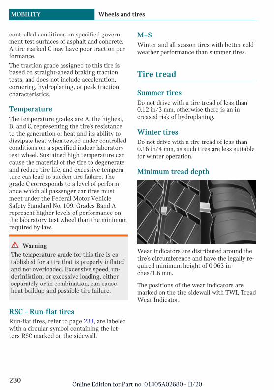
controlled conditions on specified govern-ment test surfaces of asphalt and concrete.A tire marked C may have poor traction per-formance.
The traction grade assigned to this tire isbased on straight-ahead braking tractiontests, and does not include acceleration,cornering, hydroplaning, or peak tractioncharacteristics.
TemperatureThe temperature grades are A, the highest,B, and C, representing the tire's resistanceto the generation of heat and its ability todissipate heat when tested under controlledconditions on a specified indoor laboratorytest wheel. Sustained high temperature cancause the material of the tire to degenerateand reduce tire life, and excessive tempera-ture can lead to sudden tire failure. Thegrade C corresponds to a level of perform-ance which all passenger car tires mustmeet under the Federal Motor VehicleSafety Standard No. 109. Grades Band Arepresent higher levels of performance onthe laboratory test wheel than the minimumrequired by law.
Warning
The temperature grade for this tire is es-tablished for a tire that is properly inflatedand not overloaded. Excessive speed, un-derinflation, or excessive loading, eitherseparately or in combination, can causeheat buildup and possible tire failure.
RSC – Run-flat tiresRun-flat tires, refer to page 233, are labeledwith a circular symbol containing the let-ters RSC marked on the sidewall.
M+SWinter and all-season tires with better coldweather performance than summer tires.
Tire tread
Summer tiresDo not drive with a tire tread of less than0.12 in/3 mm, otherwise there is an in-creased risk of hydroplaning.
Winter tiresDo not drive with a tire tread of less than0.16 in/4 mm, as such tires are less suitablefor winter operation.
Minimum tread depth
Wear indicators are distributed around thetire's circumference and have the legally re-quired minimum height of 0.063 in-ches/1.6 mm.
The positions of the wear indicators aremarked on the tire sidewall with TWI, TreadWear Indicator.
Seite 230
MOBILITY Wheels and tires
230Online Edition for Part no. 01405A02680 - II/20

Tire damage
General informationInspect your tires regularly for damage, for-eign objects lodged in the tread, and treadwear.
Driving over rough or damaged road surfa-ces, as well as debris, curbs and other obsta-cles can cause serious damage to wheels,tires and suspension parts. This is morelikely to occur with low-profile tires, whichprovide less cushioning between the wheeland the road. Be careful to avoid road haz-ards and reduce your speed, especially ifyour vehicle is equipped with low-profiletires.
Indications of tire damage or other vehiclemalfunctions:
– Unusual vibrations.
– Unusual tire or running noises.
– Unusual handling such as a strong ten-dency to pull to the left or right.
Damage can be caused by the following sit-uations, for instance:
– Driving over curbs.
– Road damage.
– Tire inflation pressure too low.
– Vehicle overloading.
– Incorrect tire storage.
Safety information
Warning
Damaged tires can lose tire inflation pres-sure, which can lead to loss of vehicle con-trol. There is a risk of accident. If tire dam-age is suspected while driving,immediately reduce speed and stop. Havewheels and tires checked. For this pur-pose, drive carefully to the nearest dealer’sservice center or another qualified service
center or repair shop. Have vehicle towedor transported as needed. Do not repairdamaged tires, but have them replaced.
Warning
Tires can become damaged by driving overobstacles, e.g., curbs or road damage, athigh speed. Larger wheels have a smallertire cross-section. The smaller the tirecross-section, the higher the risk of tiredamage. There is a danger of accidents andproperty damage. If possible, avoid drivingover objects or road conditions that maydamage tires, or drive over them slowlyand carefully.
Changing wheels and tires
Mounting and wheel balancingHave mounting and tire and wheel balanc-ing carried out by a dealer’s service centeror another qualified service center or repairshop.
Light-alloy rim MINI Electric CoronaSpoke 2 Tone
A balancing weight is required for wheelbalancing.
The balancing weight is available as a spe-cial tool from a dealer’s service center, an-
Seite 231
Wheels and tires MOBILITY
231Online Edition for Part no. 01405A02680 - II/20
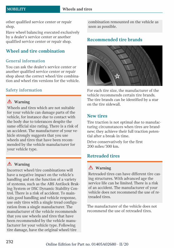
other qualified service center or repairshop.
Have wheel balancing executed exclusivelyby a dealer’s service center or anotherqualified service center or repair shop.
Wheel and tire combination
General informationYou can ask the dealer's service center oranother qualified service center or repairshop about the correct wheel/tire combina-tion and wheel rim versions for the vehicle.
Safety information
Warning
Wheels and tires which are not suitablefor your vehicle can damage parts of thevehicle, for instance due to contact withthe body due to tolerances despite thesame official size rating. There is a risk ofan accident. The manufacturer of your ve-hicle strongly suggests that you usewheels and tires that have been recom-mended by the vehicle manufacturer foryour vehicle type.
Warning
Incorrect wheel/tire combinations willhave a negative impact on the vehicle'shandling and on the function of a varietyof systems, such as the ABS Antilock Brak-ing System or DSC Dynamic Stability Con-trol. There is a risk of accident. To main-tain good handling and vehicle response,use only tires with a single tread configu-ration from a single manufacturer. Themanufacturer of the vehicle recommendsthat you use wheels and tires that havebeen recommended by the vehicle manu-facturer for your vehicle type. Followingtire damage, have the original wheel/tire
combination remounted on the vehicle assoon as possible.
Recommended tire brands
For each tire size, the manufacturer of thevehicle recommends certain tire brands.The tire brands can be identified by a staron the tire sidewall.
New tiresTire traction is not optimal due to manufac-turing circumstances when tires are brand-new; they achieve their full traction poten-tial after a break-in time.
Drive conservatively for the first200 miles/300 km.
Retreaded tires
Warning
Retreaded tires can have different tire cas-ing structures. With advanced age theservice life can be limited. There is a riskof an accident. The manufacturer of yourvehicle does not recommend the use of re-treaded tires.
The manufacturer of the vehicle does notrecommend the use of retreaded tires.
Seite 232
MOBILITY Wheels and tires
232Online Edition for Part no. 01405A02680 - II/20
Winter tiresWinter tires are recommended for operat-ing on winter roads.
Although so-called all-season M+S tires pro-vide better winter traction than summertires, they usually do not provide the samelevel of performance as winter tires.
Maximum speed of winter tiresIf the maximum speed of the vehicle ishigher than the permissible speed for thewinter tires, then attach a label showing thepermissible maximum speed in the field ofview. The label is available from a dealer'sservice center or another qualified servicecenter or repair shop.
With winter tires mounted, observe and donot exceed the permissible maximum speed.
Changing runflat tiresFor your own safety, use only runflat tires.Further information is available from a deal-er's service center or another qualified serv-ice center or repair shop.
Rotating wheels between axlesDifferent wear patterns can occur on thefront and rear axles depending on individualdriving conditions. The tires can be rotatedin pairs between the axles to achieve evenwear. Further information is available froma dealer's service center or another qualifiedservice center or repair shop. After rotating,check the tire pressure and correct, ifneeded.
Storing tires
Tire inflation pressureDo not exceed the maximum tire inflationpressure indicated on the side wall of thetire.
StorageStore wheels and tires in a cool, dry anddark place.
Always protect tires against all contact withoil, grease, and solvents.
Do not leave tires in plastic bags.
Remove dirt from wheels or tires.
Run-flat tires
ConceptRun-flat tires permit continued driving un-der restricted conditions even in the eventof a complete loss of tire inflation pressure.
General informationThe wheels are composed of tires that areself-supporting to a limited degree.
The support of the sidewall allows the tireto remain drivable to a restricted degree inthe event of a tire inflation pressure loss.
Follow the instructions for continued driv-ing with a flat tire.
Safety information
Warning
The vehicle handles differently when arun-flat tire has insufficient or no tirepressure; for instance, reduced lane stabil-ity when braking, braking distances arelonger and the self-steering properties willchange. There is a risk of accident. Drivemoderately and do not exceed a speed of50 mph/80 km/h.
Seite 233
Wheels and tires MOBILITY
233Online Edition for Part no. 01405A02680 - II/20

Label
The tires are marked on the tire sidewallwith RSC Run-flat System Component.
Repairing a flat tire
Safety measures– Park the vehicle as far away as possible
from passing traffic and on solid ground.
– Switch on the hazard warning system.
– Secure the vehicle against rolling awayby setting the parking brake.
– Turn the steering wheel until the frontwheels are in the straight-ahead posi-tion and engage the steering wheel lock.
– Have all vehicle occupants get out of thevehicle and ensure that they remain out-side the immediate area in a safe place,such as behind a guardrail.
– If necessary, set up a warning triangleat an appropriate distance.
Mobility System
ConceptWith the Mobility System, minor tire dam-age can be sealed temporarily to enable con-tinued travel. To accomplish this, sealant ispumped into the tires, which seals the dam-age from the inside.
General information– Follow the instructions on using the
Mobility System found on the compres-sor and sealant container.
– Use of the Mobility System may be inef-fective if the tire puncture measures ap-prox. 1/8 inches/4 mm or more.
– Contact a dealer's service center or an-other qualified service center or repairshop if the tire cannot be made drivable.
– Do not remove foreign bodies that havepenetrated the tire. Only remove foreignobjects if they are visibly protrudingfrom the tire.
– Pull the speed limit sticker off the seal-ant container and apply it to the steer-ing wheel.
– The use of a sealant can damage theTPM wheel electronics. In this case,have the TPM wheel electronics re-placed at the next opportunity.
– The compressor can be used to checkthe tire inflation pressure.
Overview
StorageThe Mobility System is in a bag on the rightside of the cargo area.
Sealant container
– Sealant container, arrow 1.
– Filling hose, arrow 2.
Seite 234
MOBILITY Wheels and tires
234Online Edition for Part no. 01405A02680 - II/20

Observe use-by date on the sealant con-tainer.
Compressor
1 Sealant container unlocking
2 Sealant container holder
3 Tire pressure gage
4 Reduce tire inflation pressure button
5 On/off switch
6 Compressor
7 Connector/cable for socket
8 Connection hose
Safety measures– Park the vehicle as far away as possible
from passing traffic and on solid ground.
– Switch on the hazard warning system.
– Secure the vehicle against rolling awayby setting the parking brake.
– Turn the steering wheel until the frontwheels are in the straight-ahead posi-tion and engage the steering wheel lock.
– Have all vehicle occupants get out of thevehicle and ensure that they remain out-side the immediate area in a safe place,such as behind a guardrail.
– If necessary, set up a warning triangleat an appropriate distance.
Filling the tire with sealant
Safety information
NOTICE
The compressor can overheat during ex-tended operation. There is a risk of dam-age to property. Do not run the compres-sor for more than 10 minutes.
Filling1. Shake the sealant container.
2. Pull filling hose completely out of thecover of the sealant container. Do notkink the hose.
Seite 235
Wheels and tires MOBILITY
235Online Edition for Part no. 01405A02680 - II/20
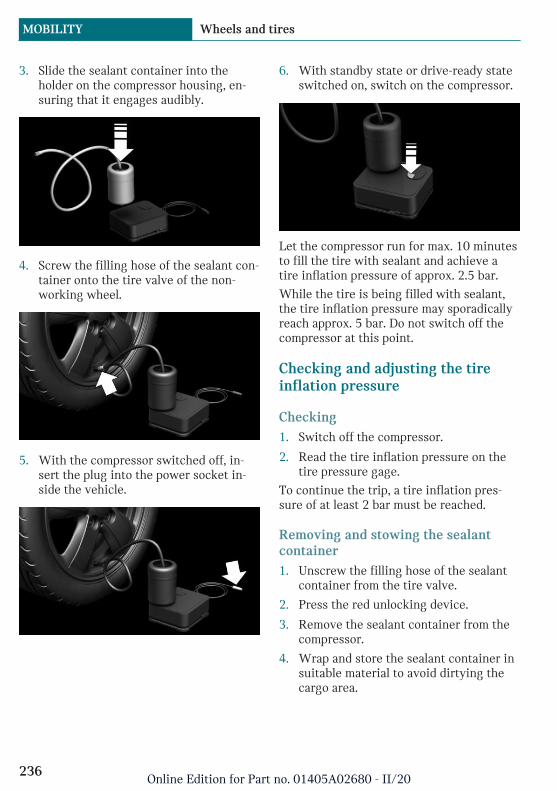
3. Slide the sealant container into theholder on the compressor housing, en-suring that it engages audibly.
4. Screw the filling hose of the sealant con-tainer onto the tire valve of the non-working wheel.
5. With the compressor switched off, in-sert the plug into the power socket in-side the vehicle.
6. With standby state or drive-ready stateswitched on, switch on the compressor.
Let the compressor run for max. 10 minutesto fill the tire with sealant and achieve atire inflation pressure of approx. 2.5 bar.
While the tire is being filled with sealant,the tire inflation pressure may sporadicallyreach approx. 5 bar. Do not switch off thecompressor at this point.
Checking and adjusting the tireinflation pressure
Checking1. Switch off the compressor.
2. Read the tire inflation pressure on thetire pressure gage.
To continue the trip, a tire inflation pres-sure of at least 2 bar must be reached.
Removing and stowing the sealantcontainer1. Unscrew the filling hose of the sealant
container from the tire valve.
2. Press the red unlocking device.
3. Remove the sealant container from thecompressor.
4. Wrap and store the sealant container insuitable material to avoid dirtying thecargo area.
Seite 236
MOBILITY Wheels and tires
236Online Edition for Part no. 01405A02680 - II/20
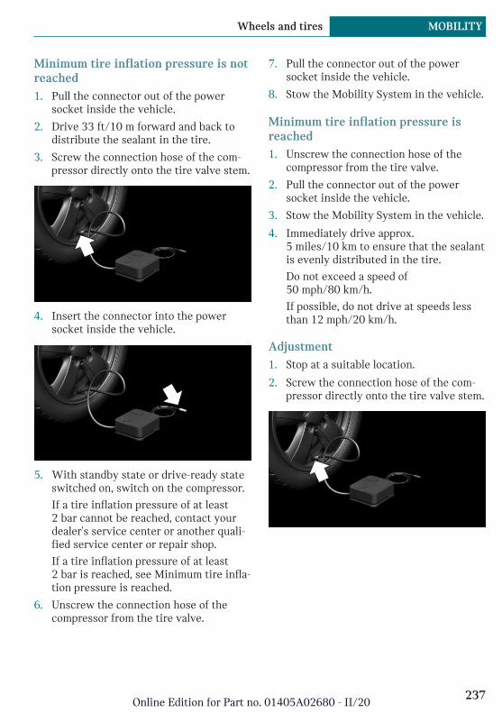
Minimum tire inflation pressure is notreached1. Pull the connector out of the power
socket inside the vehicle.
2. Drive 33 ft/10 m forward and back todistribute the sealant in the tire.
3. Screw the connection hose of the com-pressor directly onto the tire valve stem.
4. Insert the connector into the powersocket inside the vehicle.
5. With standby state or drive-ready stateswitched on, switch on the compressor.
If a tire inflation pressure of at least2 bar cannot be reached, contact yourdealer's service center or another quali-fied service center or repair shop.
If a tire inflation pressure of at least2 bar is reached, see Minimum tire infla-tion pressure is reached.
6. Unscrew the connection hose of thecompressor from the tire valve.
7. Pull the connector out of the powersocket inside the vehicle.
8. Stow the Mobility System in the vehicle.
Minimum tire inflation pressure isreached1. Unscrew the connection hose of the
compressor from the tire valve.
2. Pull the connector out of the powersocket inside the vehicle.
3. Stow the Mobility System in the vehicle.
4. Immediately drive approx.5 miles/10 km to ensure that the sealantis evenly distributed in the tire.
Do not exceed a speed of50 mph/80 km/h.
If possible, do not drive at speeds lessthan 12 mph/20 km/h.
Adjustment1. Stop at a suitable location.
2. Screw the connection hose of the com-pressor directly onto the tire valve stem.
Seite 237
Wheels and tires MOBILITY
237Online Edition for Part no. 01405A02680 - II/20

3. Insert the connector into the powersocket inside the vehicle.
4. Correct the tire inflation pressure to atleast 2.0 bar.
– Increase tire inflation pressure: withstandby state or drive-ready state,switch on the compressor.
– Reduce tire inflation pressure: pressthe button on the compressor.
5. Unscrew the connection hose of thecompressor from the tire valve.
6. Pull the connector out of the powersocket inside the vehicle.
7. Stow the Mobility System in the vehicle.
Continuing the tripDo not exceed the maximum permissiblespeed of 50 mph/80 km/h.
Reinitialize the Flat Tire Monitor, refer topage 150.
Reset the Tire Pressure Monitor, refer topage 145.
Replace the nonworking tire and the sealantcontainer of the Mobility System promptly.
Snow chains
General informationThe manufacturer of the vehicle has deter-mined certain wheels and tires to be suita-ble for operation on the vehicle. Mounting
of snow chains on these wheels and tires isnot permitted.
Safety information
Warning
With the mounting of snow chains on un-suitable tires, the snow chains can comeinto contact with vehicle parts. There maybe a risk of accident or risk of damage toproperty. Do not mount snow chains.
Changing wheels/tires
General informationWhen using run-flat tires or a flat tire kit, awheel does not always need to be changedimmediately when there is a loss of tire in-flation pressure due to a flat tire.
If needed, the tools for changing wheels areavailable as accessories from a dealer’sservice center or another qualified servicecenter or repair shop.
Safety information
DANGER
The vehicle jack is only provided for short-term lifting of the vehicle for wheelchanges. Even if all safety measures areobserved, there is a risk of the raised vehi-cle falling, if the vehicle jack tips over.There is a risk of injuries or danger to life.When the vehicle is raised with the vehi-cle jack, do not lie under the vehicle anddo not switch on the drive-ready state.
Seite 238
MOBILITY Wheels and tires
238Online Edition for Part no. 01405A02680 - II/20
DANGER
Supports such as wooden blocks under thevehicle jack reduce the capacity of the ve-hicle jack to bear weight. They have thepotential to exert too much strain on thevehicle jack, causing it to tip over and thevehicle to fall. There is a risk of injuries ordanger to life. Do not place supports underthe vehicle jack.
Warning
The jack, issued by the vehicle manufac-turer, is provided in order to perform awheel change in the event of a breakdown.The jack is not designed for frequent use;for example, changing from summer towinter tires. Using the jack frequently maycause it to become jammed or damaged.There is a risk of injury and risk of damageto property. Only use the jack to attach anemergency or spare wheel in the event ofa breakdown.
Warning
On soft, uneven or slippery ground, for ex-ample snow, ice, tiles, etc., the vehicle jackcan slip away. There is a risk of injury. Ifpossible, change the wheel on a flat, solid,and slip-resistant surface.
Warning
The vehicle jack is optimized for liftingthe vehicle and for the jacking points onthe vehicle only. There is a risk of injury.Do not lift any other vehicle or cargo usingthe vehicle jack.
Warning
When the vehicle jack is not inserted intothe jacking point provided for this pur-pose, the vehicle may be damaged or thevehicle jack may slip when it is beingcranked up. There is a risk of injury or riskof damage to property. When cranking upthe vehicle jack, ensure that it is insertedin the jacking point next to the wheelhousing.
Warning
A vehicle that is raised on a vehicle jackmay fall off of the jack if lateral forces areexerted on it. There is a risk of injury andrisk of damage to property. While the ve-hicle is raised, do not exert lateral forceson the vehicle or pull abruptly on the vehi-cle. Have a stuck wheel removed by a deal-er’s service center or another qualifiedservice center or repair shop.
Securing the vehicle against rolling
General informationThe vehicle manufacturer recommends toadditionally secure the vehicle against roll-ing away when changing a wheel.
Seite 239
Wheels and tires MOBILITY
239Online Edition for Part no. 01405A02680 - II/20

On a level surface
Place wheel chocks or other suitable objectsin front and behind the wheel that is diago-nal to the wheel to be changed.
On a slight downhill gradient
If you need to change a wheel on a slightdownhill grade, place chocks and other suit-able objects, for instance a rock, under thewheels of both the front and rear axlesagainst the rolling direction.
Preparing the vehicle– Park the vehicle on solid and non-slip
ground at a safe distance from traffic.
– Switch on the hazard warning system.
– Set the parking brake.
– Engage a gear or move the selector leverto position P.
– As soon as permitted by the traffic flow,have all vehicle occupants get out of thevehicle and ensure that they remain out-
side the immediate area in a safe place,such as behind a guardrail.
– Depending on the vehicle equipment,get wheel change tools and, if necessary,the emergency wheel from the vehicle.
– If necessary, set up a warning triangleor portable hazard warning light at anappropriate distance.
– Secure the vehicle additionally againstrolling.
– Loosen the lug bolts a half turn.
Jacking points for the vehicle jack
The jacking points for the vehicle jack arelocated at the marked positions.
Seite 240
MOBILITY Wheels and tires
240Online Edition for Part no. 01405A02680 - II/20
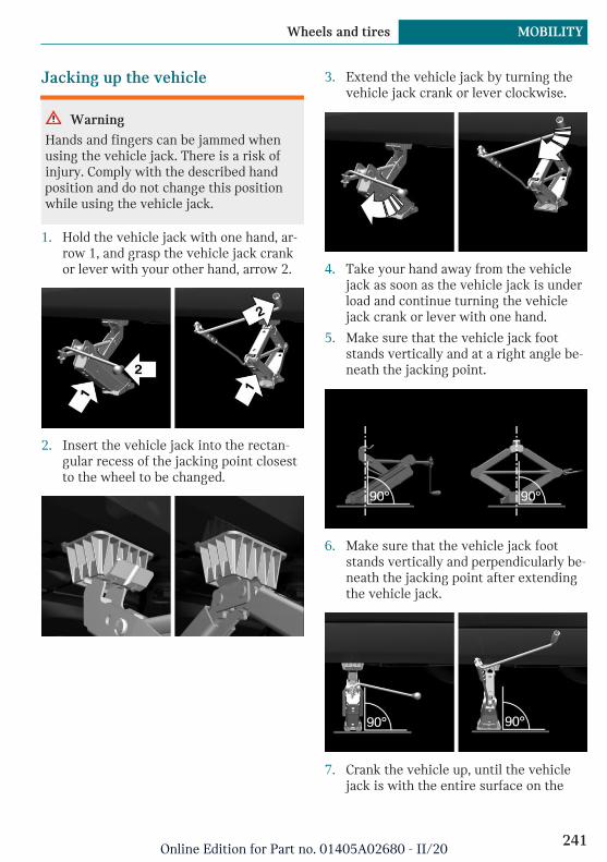
Jacking up the vehicle
Warning
Hands and fingers can be jammed whenusing the vehicle jack. There is a risk ofinjury. Comply with the described handposition and do not change this positionwhile using the vehicle jack.
1. Hold the vehicle jack with one hand, ar-row 1, and grasp the vehicle jack crankor lever with your other hand, arrow 2.
2. Insert the vehicle jack into the rectan-gular recess of the jacking point closestto the wheel to be changed.
3. Extend the vehicle jack by turning thevehicle jack crank or lever clockwise.
4. Take your hand away from the vehiclejack as soon as the vehicle jack is underload and continue turning the vehiclejack crank or lever with one hand.
5. Make sure that the vehicle jack footstands vertically and at a right angle be-neath the jacking point.
6. Make sure that the vehicle jack footstands vertically and perpendicularly be-neath the jacking point after extendingthe vehicle jack.
7. Crank the vehicle up, until the vehiclejack is with the entire surface on the
Seite 241
Wheels and tires MOBILITY
241Online Edition for Part no. 01405A02680 - II/20

ground and the relevant wheel is maxi-mum 1.2 inches/3 cm above ground.
Mounting a wheelMount one emergency wheel only, as re-quired.
1. Unscrew the lug bolts.
2. Remove the wheel.
3. Put the new wheel or emergency wheelon and screw in at least two lug bolts ina crosswise pattern until hand-tight.
If non-original light-alloy wheels of thevehicle manufacturer are mounted, theaccompanying lug bolts may have to beused as well.
4. Hand-tighten the remaining lug boltsand tighten all lug bolts well in a cross-wise pattern.
5. Turn the vehicle jack crank counter-clockwise to retract the vehicle jack andlower the vehicle.
6. Remove the vehicle jack and stow it se-curely.
After the wheel change1. Tighten the lug bolts crosswise. The
tightening torque is 101 lbs ft/140 Nm.
2. Stow the nonworking wheel in the cargoarea, if necessary.
The nonworking wheel cannot be storedunder the cargo floor panel because ofits size.
3. Check tire inflation pressure at the nextopportunity and correct as needed.
4. Reinitialize the Flat Tire Monitor.
Reset the Tire Pressure Monitor TPM.
5. Check to make sure the lug bolts aretight with a calibrated torque wrench.
6. Have the damaged tire replaced at thenearest dealer's service center or an-
other qualified service center or repairshop.
Seite 242
MOBILITY Wheels and tires
242Online Edition for Part no. 01405A02680 - II/20

Engine compartment
Vehicle features and options
This chapter describes all standard, country-specific and optional features offered withthe series. It also describes features andfunctions that are not necessarily available
in your vehicle, e.g., due to the selected op-tions or country versions. This also appliesto safety-related functions and systems.When using these functions and systems,the applicable laws and regulations must beobserved.
Overview
1 Filler neck for washer fluid
2 Vehicle identification number
3 Jump-starting, positive terminal
4 Jump-starting, negative terminal
5 Coolant reservoir
Seite 243
Engine compartment MOBILITY
243Online Edition for Part no. 01405A02680 - II/20
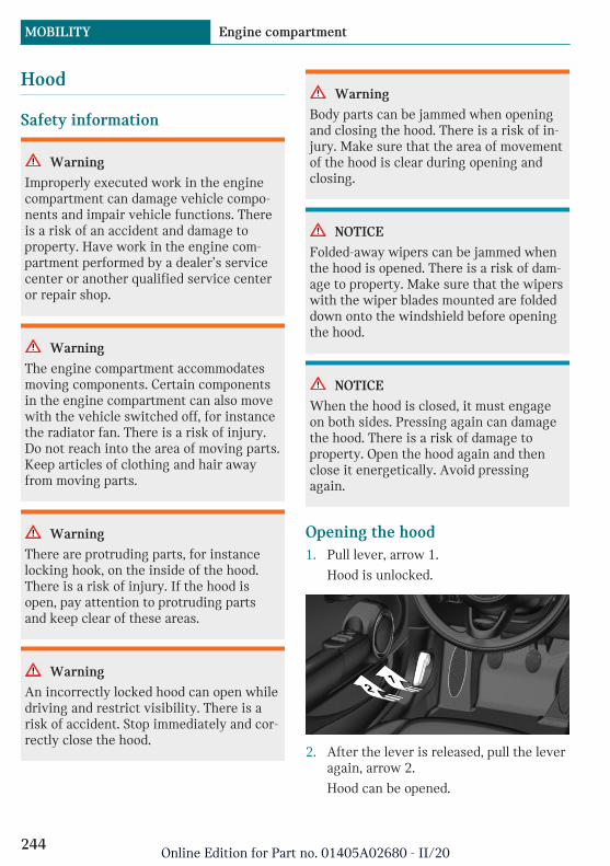
Hood
Safety information
Warning
Improperly executed work in the enginecompartment can damage vehicle compo-nents and impair vehicle functions. Thereis a risk of an accident and damage toproperty. Have work in the engine com-partment performed by a dealer’s servicecenter or another qualified service centeror repair shop.
Warning
The engine compartment accommodatesmoving components. Certain componentsin the engine compartment can also movewith the vehicle switched off, for instancethe radiator fan. There is a risk of injury.Do not reach into the area of moving parts.Keep articles of clothing and hair awayfrom moving parts.
Warning
There are protruding parts, for instancelocking hook, on the inside of the hood.There is a risk of injury. If the hood isopen, pay attention to protruding partsand keep clear of these areas.
Warning
An incorrectly locked hood can open whiledriving and restrict visibility. There is arisk of accident. Stop immediately and cor-rectly close the hood.
Warning
Body parts can be jammed when openingand closing the hood. There is a risk of in-jury. Make sure that the area of movementof the hood is clear during opening andclosing.
NOTICE
Folded-away wipers can be jammed whenthe hood is opened. There is a risk of dam-age to property. Make sure that the wiperswith the wiper blades mounted are foldeddown onto the windshield before openingthe hood.
NOTICE
When the hood is closed, it must engageon both sides. Pressing again can damagethe hood. There is a risk of damage toproperty. Open the hood again and thenclose it energetically. Avoid pressingagain.
Opening the hood1. Pull lever, arrow 1.
Hood is unlocked.
2. After the lever is released, pull the leveragain, arrow 2.
Hood can be opened.
Seite 244
MOBILITY Engine compartment
244Online Edition for Part no. 01405A02680 - II/20
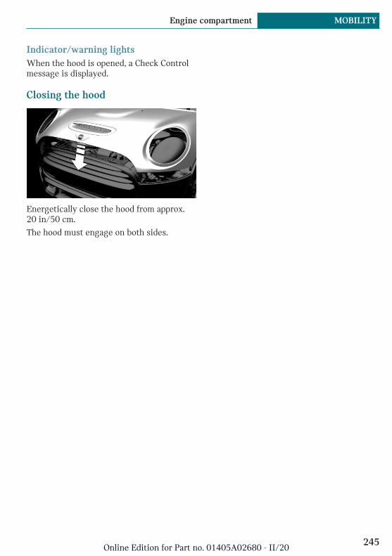
Indicator/warning lightsWhen the hood is opened, a Check Controlmessage is displayed.
Closing the hood
Energetically close the hood from approx.20 in/50 cm.
The hood must engage on both sides.
Seite 245
Engine compartment MOBILITY
245Online Edition for Part no. 01405A02680 - II/20

Coolant
Vehicle features and options
This chapter describes all standard, country-specific and optional features offered withthe series. It also describes features andfunctions that are not necessarily availablein your vehicle, e.g., due to the selected op-tions or country versions. This also appliesto safety-related functions and systems.When using these functions and systems,the applicable laws and regulations must beobserved.
General information
Coolant consists of water and additives.
Not all commercially available additives aresuitable for the vehicle. Do not mix addi-tives of different colors. Observe the water -additive mixing ratio of 50:50. Informationabout suitable additives is available from adealer’s service center or another qualifiedservice center or repair shop.
Safety information
Warning
With the drive system hot and the coolingsystem open, coolant can escape and leadto scalding. There is a risk of injury. Onlyopen the cooling system with the drivesystem cooled down.
Warning
Additives are harmful and incorrect addi-tives can damage the drive system. Thereis a risk of injury and risk of damage toproperty. Do not allow additives to comeinto contact with skin, eyes or articles ofclothing. Use suitable additives only.
NOTICE
Loss of coolant may damage the drive sys-tem. There is a risk of damage to property.Make sure that there is sufficient coolantin the reservoir at all times. Always havecoolant added by a dealer's service centeror another qualified service center or re-pair shop.
Coolant level
CheckingThere are yellow Min and Max marks in thecoolant reservoir.
1. Allow the drive system to cool down.
2. Open the hood, refer to page 244.
3. Turn the lid of the coolant reservoirslightly counterclockwise to allow any
Seite 246
MOBILITY Coolant
246Online Edition for Part no. 01405A02680 - II/20

excess pressure to dissipate, then openit.
4. Open the coolant reservoir lid.
5. The coolant level is correct if it lies be-tween the minimum and maximummarks in the filler neck.
6. Close the lid.
When the coolant level is low, check thecooling system and add coolant. Have thecooling system checked and coolant addedby a dealer’s service center or anotherqualified service center or repair shop.
Disposal
Comply with the relevant environ-mental protection regulations whendisposing of coolant and coolant ad-
ditives.
Seite 247
Coolant MOBILITY
247Online Edition for Part no. 01405A02680 - II/20

Maintenance
Vehicle features and options
This chapter describes all standard, country-specific and optional features offered withthe series. It also describes features andfunctions that are not necessarily availablein your vehicle, e.g., due to the selected op-tions or country versions. This also appliesto safety-related functions and systems.When using these functions and systems,the applicable laws and regulations must beobserved.
MINI maintenance system
The maintenance system provides servicenotifications and thereby provides supportin maintaining road safety and the opera-tional reliability of the vehicle.
In some cases, scopes and intervals of themaintenance system may vary according tothe country version. Replacement work,spare parts, fuels and lubricants, and wearmaterials are calculated separately. Furtherinformation is available from a dealer's serv-ice center or another qualified service cen-ter or repair shop.
Safety information
DANGER
Improperly performed work, in particularmaintenance and repair on the high-volt-age system, can lead to electric shock.There is a risk of injury, fire and danger tolife.
The manufacturer of your vehicle recom-mends that the work on the vehicle, in par-ticular maintenance and repair, be per-formed by a dealer’s service center oranother qualified service center or repairshop.
Condition Based Service CBS
ConceptSensors and special algorithms take into ac-count the driving conditions of the vehicle.CBS uses these to calculate the need formaintenance.
The system makes it possible to adapt theamount of maintenance corresponding toyour user profile.
General informationInformation on service notifications, referto page 126, can be displayed on the ControlDisplay.
Service data in the vehicle keyInformation on the service notifications iscontinuously stored in the vehicle key. Theservice center can read this data out andsuggest a maintenance scope for the vehi-cle.
Therefore, hand the service advisor the ve-hicle key with which the vehicle was drivenmost recently.
Storage periodsStorage periods during which the vehiclebattery was disconnected are not taken intoaccount.
Seite 248
MOBILITY Maintenance
248Online Edition for Part no. 01405A02680 - II/20

Have a dealer's service center or anotherqualified service center or repair shop up-date the time-dependent maintenance pro-cedures, such as checking brake fluid andchanging the microfilter/activated-charcoalfilter.
Maintenance Manual andService and Warranty Infor-mation Booklet for US modelsand Warranty and ServiceGuide Booklet for Canadianmodels
Please consult your Maintenance Manualand Service and Warranty InformationBooklet for US models and Warranty andService Guide Booklet for Canadian modelsfor additional information on the perform-ance of service and maintenance work.
The manufacturer of your vehicle recom-mends that maintenance and repair be per-formed by a service center or another quali-fied service center or repair shop. Recordsof regular maintenance and repair workshould be retained.
Socket for OBD Onboard Diag-nosis
General informationDevices connected to the OBD socket trig-ger the alarm system when the vehicle islocked. Remove any devices connected atthe OBD socket before locking the vehicle.
Safety information
NOTICE
The socket for Onboard Diagnosis is an in-tricate component intended to be used inconjunction with specialized equipment tocheck the vehicle’s primary emissions sys-tem. Improper use of the socket for On-board Diagnosis, or contact with thesocket for Onboard Diagnosis for otherthan its intended purpose, can cause vehi-cle malfunctions and creates risks of per-sonal and property damage. Given the fore-going, the manufacture of your vehiclestrongly recommends that access to thesocket for Onboard Diagnosis be limited toa dealer's service center or another quali-fied service center or repair shop or otherpersons that have the specialized trainingand equipment for purposes of properlyutilizing the socket for Onboard Diagnosis.
Position
There is an OBD socket on the driver's sidefor checking the primary components in thevehicle's emissions.
Seite 249
Maintenance MOBILITY
249Online Edition for Part no. 01405A02680 - II/20

Replacing components
Vehicle features and options
This chapter describes all standard, country-specific and optional features offered withthe series. It also describes features andfunctions that are not necessarily availablein your vehicle, e.g., due to the selected op-tions or country versions. This also appliesto safety-related functions and systems.When using these functions and systems,the applicable laws and regulations must beobserved.
Vehicle tool kit
Depending on the vehicle equipment, theonboard vehicle tool kit is located on theright side under the cargo floor panel or in abag on the right side of the cargo area.
After use, secure the bag with the onboardvehicle tool kit on a lashing eye again.
Wiper blades
Safety information
NOTICE
The window may sustain damage if thewiper falls onto it without the wiper bladeinstalled. There is a risk of damage toproperty. Hold the wiper firmly whenchanging the wiper blade. Do not fold orswitch on the wiper without a wiper bladeinstalled.
NOTICE
Folded-away wipers can be jammed whenthe hood is opened. There is a risk of dam-age to property. Make sure that the wiperswith the wiper blades mounted are foldeddown onto the windshield before openingthe hood.
Replacing the front wiper blades1. To change the wiper blades, fold up the
wiper arms.
2. Fold up and hold the wiper arm firmly.
3. Open the wiper blade lock, arrow.
Seite 250
MOBILITY Replacing components
250Online Edition for Part no. 01405A02680 - II/20
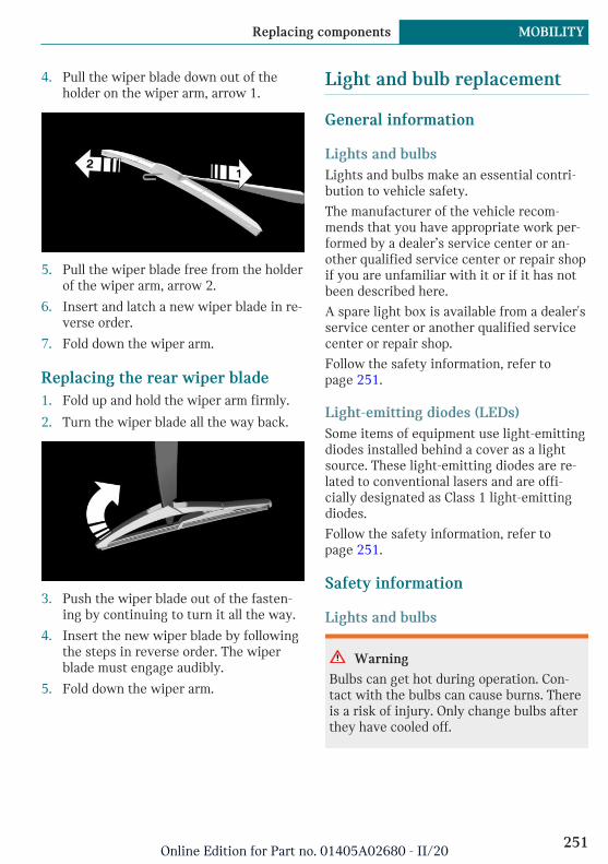
4. Pull the wiper blade down out of theholder on the wiper arm, arrow 1.
5. Pull the wiper blade free from the holderof the wiper arm, arrow 2.
6. Insert and latch a new wiper blade in re-verse order.
7. Fold down the wiper arm.
Replacing the rear wiper blade1. Fold up and hold the wiper arm firmly.
2. Turn the wiper blade all the way back.
3. Push the wiper blade out of the fasten-ing by continuing to turn it all the way.
4. Insert the new wiper blade by followingthe steps in reverse order. The wiperblade must engage audibly.
5. Fold down the wiper arm.
Light and bulb replacement
General information
Lights and bulbsLights and bulbs make an essential contri-bution to vehicle safety.
The manufacturer of the vehicle recom-mends that you have appropriate work per-formed by a dealer’s service center or an-other qualified service center or repair shopif you are unfamiliar with it or if it has notbeen described here.
A spare light box is available from a dealer'sservice center or another qualified servicecenter or repair shop.
Follow the safety information, refer topage 251.
Light-emitting diodes (LEDs)Some items of equipment use light-emittingdiodes installed behind a cover as a lightsource. These light-emitting diodes are re-lated to conventional lasers and are offi-cially designated as Class 1 light-emittingdiodes.
Follow the safety information, refer topage 251.
Safety information
Lights and bulbs
Warning
Bulbs can get hot during operation. Con-tact with the bulbs can cause burns. Thereis a risk of injury. Only change bulbs afterthey have cooled off.
Seite 251
Replacing components MOBILITY
251Online Edition for Part no. 01405A02680 - II/20
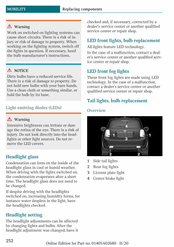
Warning
Work on switched-on lighting systems cancause short circuits. There is a risk of in-jury or risk of damage to property. Whenworking on the lighting system, switch offthe lights in question. If necessary, heedthe bulb manufacturer's instructions.
NOTICE
Dirty bulbs have a reduced service life.There is a risk of damage to property. Donot hold new bulbs with your bare hands.Use a clean cloth or something similar, orhold the bulb by its base.
Light-emitting diodes (LEDs)
Warning
Intensive brightness can irritate or dam-age the retina of the eye. There is a risk ofinjury. Do not look directly into the head-lights or other light sources. Do not re-move the LED covers.
Headlight glassCondensation can form on the inside of theheadlight glass in cool or humid weather.When driving with the lights switched on,the condensation evaporates after a shorttime. The headlight glass does not need tobe changed.
If despite driving with the headlightsswitched on, increasing humidity forms, forinstance water droplets in the light, havethe headlights checked.
Headlight settingThe headlight adjustments can be affectedby changing lights and bulbs. After theheadlight adjustment was changed, have it
checked and, if necessary, corrected by adealer’s service center or another qualifiedservice center or repair shop.
LED front lights, bulb replacementAll lights feature LED technology.
In the case of a malfunction, contact a deal-er's service center or another qualified serv-ice center or repair shop.
LED front fog lightsThese front fog lights are made using LEDtechnology. In the case of a malfunction,contact a dealer's service center or anotherqualified service center or repair shop.
Tail lights, bulb replacement
Overview
1 Side tail lights
2 Rear fog lights
3 License plate light
4 Center brake light
Seite 252
MOBILITY Replacing components
252Online Edition for Part no. 01405A02680 - II/20
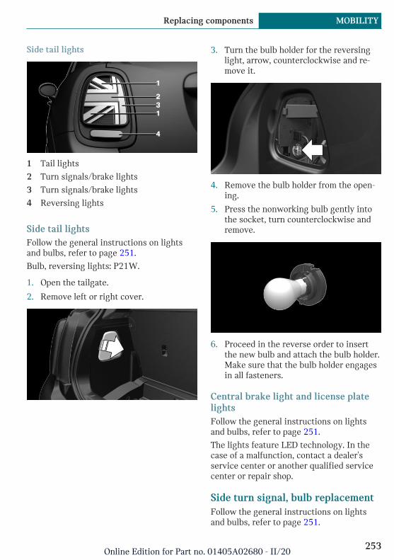
Side tail lights
1 Tail lights
2 Turn signals/brake lights
3 Turn signals/brake lights
4 Reversing lights
Side tail lightsFollow the general instructions on lightsand bulbs, refer to page 251.
Bulb, reversing lights: P21W.
1. Open the tailgate.
2. Remove left or right cover.
3. Turn the bulb holder for the reversinglight, arrow, counterclockwise and re-move it.
4. Remove the bulb holder from the open-ing.
5. Press the nonworking bulb gently intothe socket, turn counterclockwise andremove.
6. Proceed in the reverse order to insertthe new bulb and attach the bulb holder.Make sure that the bulb holder engagesin all fasteners.
Central brake light and license platelightsFollow the general instructions on lightsand bulbs, refer to page 251.
The lights feature LED technology. In thecase of a malfunction, contact a dealer'sservice center or another qualified servicecenter or repair shop.
Side turn signal, bulb replacementFollow the general instructions on lightsand bulbs, refer to page 251.
Seite 253
Replacing components MOBILITY
253Online Edition for Part no. 01405A02680 - II/20
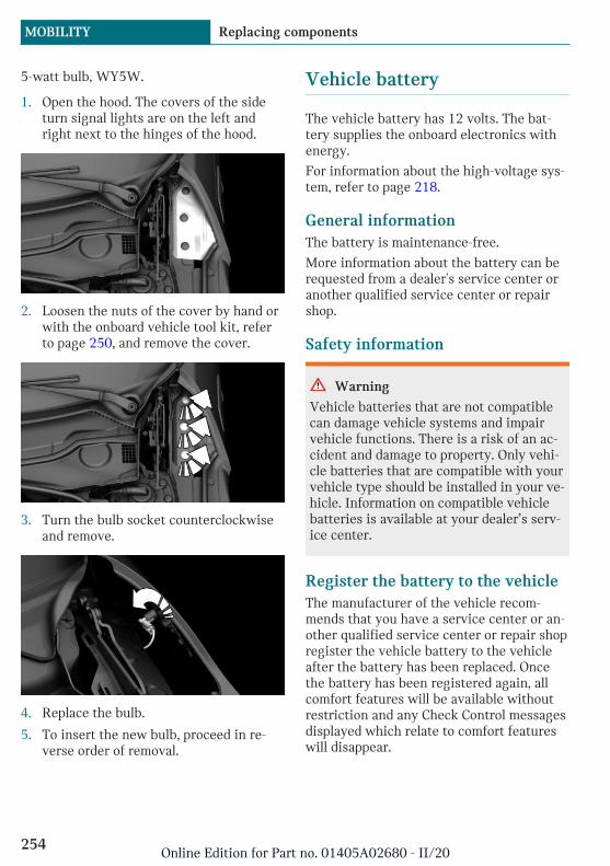
5-watt bulb, WY5W.
1. Open the hood. The covers of the sideturn signal lights are on the left andright next to the hinges of the hood.
2. Loosen the nuts of the cover by hand orwith the onboard vehicle tool kit, referto page 250, and remove the cover.
3. Turn the bulb socket counterclockwiseand remove.
4. Replace the bulb.
5. To insert the new bulb, proceed in re-verse order of removal.
Vehicle battery
The vehicle battery has 12 volts. The bat-tery supplies the onboard electronics withenergy.
For information about the high-voltage sys-tem, refer to page 218.
General informationThe battery is maintenance-free.
More information about the battery can berequested from a dealer's service center oranother qualified service center or repairshop.
Safety information
Warning
Vehicle batteries that are not compatiblecan damage vehicle systems and impairvehicle functions. There is a risk of an ac-cident and damage to property. Only vehi-cle batteries that are compatible with yourvehicle type should be installed in your ve-hicle. Information on compatible vehiclebatteries is available at your dealer’s serv-ice center.
Register the battery to the vehicleThe manufacturer of the vehicle recom-mends that you have a service center or an-other qualified service center or repair shopregister the vehicle battery to the vehicleafter the battery has been replaced. Oncethe battery has been registered again, allcomfort features will be available withoutrestriction and any Check Control messagesdisplayed which relate to comfort featureswill disappear.
Seite 254
MOBILITY Replacing components
254Online Edition for Part no. 01405A02680 - II/20

Charging the battery
General informationFor charging a discharged battery, refer topage 226.
Safety information
NOTICE
Battery chargers for the vehicle batterycan work with high voltages and currents,which means that the 12 volt on-boardnetwork can be overloaded or damaged.There is a risk of damage to property. Onlyconnect battery chargers for the vehiclebattery to the starting aid terminals in theengine compartment.
Power failureAfter a power loss, some equipment needsto be newly initialized or individual settingsupdated, for example:
– Memory function: store the positionsagain.
– Time: update.
– Date: update.
– Glass sunroof: initialize the system.
Disposing of old batteriesHave old batteries disposed of by adealer’s service center or anotherqualified service center or repair
shop or take them to a collection point.
Maintain the filled battery in an upright po-sition for transport and storage. Secure thebattery so that it does not tip over duringtransport.
Fuses
Safety information
Warning
Incorrect and repaired fuses can overloadelectrical lines and components. There is arisk of fire. Never attempt to repair ablown fuse. Do not replace a nonworkingfuse with a substitute of another color oramperage rating.
Accessing the fusesThe fuses are located in the glove compart-ment.
1. Open the glove compartment.
2. Swing the cover down, arrow.
Information on the fuse types and locations,as well as the positions of any other fuseboxes, is available on the Internet:www.mini.com/fusecard.
Where applicable, information on the fusetypes and locations is also found on a sepa-rate sheet in the fuse box.
Replacing fusesThe vehicle manufacturer recommends thatyou have a dealer's service center or an-other qualified service center or repair shopreplace the fuses.
Seite 255
Replacing components MOBILITY
255Online Edition for Part no. 01405A02680 - II/20

Breakdown assistance
Vehicle features and options
This chapter describes all standard, country-specific and optional features offered withthe series. It also describes features andfunctions that are not necessarily availablein your vehicle, e.g., due to the selected op-tions or country versions. This also appliesto safety-related functions and systems.When using these functions and systems,the applicable laws and regulations must beobserved.
Hazard warning flashers
The button is located above the Control Dis-play.
The red light in the button flashes when thehazard warning flashers are activated.
Warning triangle
The warning triangle is located in the tail-gate. To remove, loosen the brackets.
First-aid kit
General informationSome of the articles have a limited servicelife.
Check the expiration dates of the contentsregularly and replace any expired itemspromptly.
StorageThe first-aid kit is located in the cargo area.
MINI Roadside Assistance
ConceptMINI Roadside Assistance can be contactedif assistance is needed in the event of abreakdown.
Seite 256
MOBILITY Breakdown assistance
256Online Edition for Part no. 01405A02680 - II/20
General informationIn the event of a breakdown, data on the ve-hicle's condition is sent to the vehicle man-ufacturer.
There are various ways of making contact.
– Via a Check Control message, refer topage 121.
– Calling with a mobile phone.
Requirements– Active MINI Connected contract or
equipment version with intelligentemergency call.
– Cellular network reception.
– Standby state is switched on.
StartingIf the vehicle is equipped with Teleservices,support is offered through Teleservice Diag-nosis.
Via the Central Information Display (CID):
1. "MINI Connected"
2. "MINI Assist"
3. "MINI Roadside Assistance"
The contact to the Roadside Assistanceof the manufacture is established.
A telephone number is displayed, ifneeded. Select to dial the telephonenumber on a connected mobile phone.
Teleservice DiagnosisTeleservice Diagnosis enables the wirelesstransmission of detailed vehicle data that isimportant for vehicle diagnosis. This data istransmitted automatically.
Teleservice HelpDepending on the country, the TeleserviceHelp enables a more in-depth diagnosis ofthe vehicle via wireless transmission.
You can launch Teleservice Help by re-questing it through the Service Specialist.
1. Park the vehicle in a safe place.
2. Set the parking brake.
3. Control Display is switched on.
4. Confirm Teleservice Help.
The driving ability of the vehicle can be re-stored for specific functions.
If this is not possible, further measures willbe initiated, for instance Roadside Assis-tance will be informed.
Emergency Request
Intelligent emergency call
ConceptIn case of an emergency, an Emergency Re-quest can be triggered automatically by thesystem or manually.
General informationOnly press the SOS button in an emergency.
The Intelligent Assist system establishes aconnection with the MINI Response Center.
For technical reasons, the Emergency Re-quest cannot be guaranteed under unfavora-ble conditions.
Seite 257
Breakdown assistance MOBILITY
257Online Edition for Part no. 01405A02680 - II/20
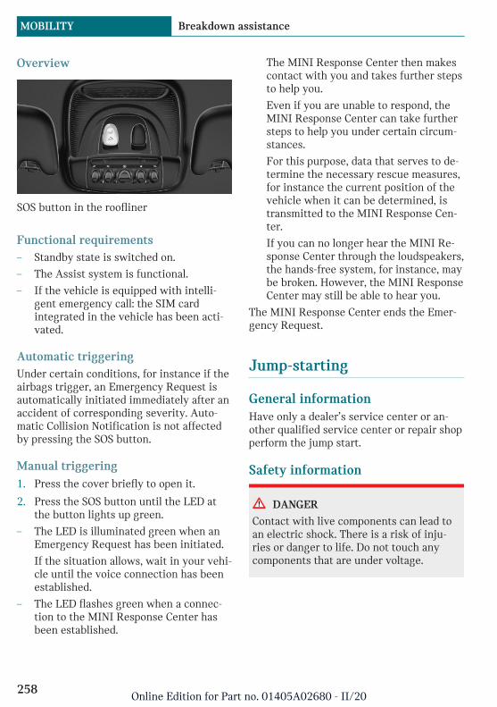
Overview
SOS button in the roofliner
Functional requirements– Standby state is switched on.
– The Assist system is functional.
– If the vehicle is equipped with intelli-gent emergency call: the SIM cardintegrated in the vehicle has been acti-vated.
Automatic triggeringUnder certain conditions, for instance if theairbags trigger, an Emergency Request isautomatically initiated immediately after anaccident of corresponding severity. Auto-matic Collision Notification is not affectedby pressing the SOS button.
Manual triggering1. Press the cover briefly to open it.
2. Press the SOS button until the LED atthe button lights up green.
– The LED is illuminated green when anEmergency Request has been initiated.
If the situation allows, wait in your vehi-cle until the voice connection has beenestablished.
– The LED flashes green when a connec-tion to the MINI Response Center hasbeen established.
The MINI Response Center then makescontact with you and takes further stepsto help you.
Even if you are unable to respond, theMINI Response Center can take furthersteps to help you under certain circum-stances.
For this purpose, data that serves to de-termine the necessary rescue measures,for instance the current position of thevehicle when it can be determined, istransmitted to the MINI Response Cen-ter.
If you can no longer hear the MINI Re-sponse Center through the loudspeakers,the hands-free system, for instance, maybe broken. However, the MINI ResponseCenter may still be able to hear you.
The MINI Response Center ends the Emer-gency Request.
Jump-starting
General informationHave only a dealer’s service center or an-other qualified service center or repair shopperform the jump start.
Safety information
DANGER
Contact with live components can lead toan electric shock. There is a risk of inju-ries or danger to life. Do not touch anycomponents that are under voltage.
Seite 258
MOBILITY Breakdown assistance
258Online Edition for Part no. 01405A02680 - II/20

Towing
Transporting the vehicle
General informationThe vehicle is not permitted to be towed.
Safety information
NOTICE
The vehicle can be damaged when towingthe vehicle with a single lifted axle. Thereis a risk of damage to property. The vehi-cle should only be transported on a loadingplatform.
Pushing the vehicleTo remove a broken-down vehicle from thedanger area, push it for a short distance at aspeed of no more than 6 mph/10 km/h.
For rolling or pushing the vehicle, refer topage 103.
Tow truck
The vehicle should only be transported on aloading platform.
NOTICE
The vehicle can become damaged whenlifting and securing it.
There is a risk of damage to property.
– Lift the vehicle using suitable means.
– Do not lift or secure the vehicle by itstow fitting, body parts, or suspensionparts.
Towing other vehicles
General informationSwitch on the hazard warning system, de-pending on local regulations.
If the electrical system has failed, clearlyidentify the vehicle being towed by placinga sign or a warning triangle in the rear win-dow.
Safety information
Warning
If the approved gross vehicle weight of thetowing vehicle is lighter than the vehicleto be towed, the tow fitting can tear off orit will not be possible to control the vehi-cle's response. There is a risk of accident.Make sure that the gross vehicle weight ofthe towing vehicle is heavier than the ve-hicle to be towed.
NOTICE
If the tow bar or tow rope is attached in-correctly, damage to other vehicle partscan occur. There is a risk of damage toproperty. Correctly attach the tow bar ortow rope to the tow fitting.
Tow barThe tow fittings used should be on the sameside on both vehicles.
Should it prove impossible to avoid mount-ing the tow bar at an offset angle, please fol-low the following:
Seite 259
Breakdown assistance MOBILITY
259Online Edition for Part no. 01405A02680 - II/20

– Maneuvering capability is limited goingaround corners.
– The tow bar will generate lateral forcesif it is secured with an offset.
Tow ropeObserve the following notes when using thetow rope:
– Use nylon ropes or straps, which will en-able the vehicle to be towed withoutjerking.
– Make sure the tow rope is not twistedwhen fastening.
– Check the fastening of the tow fittingand tow rope in regular intervals.
– Do not exceed a towing speed of30 mph/50 km/h.
– Do not exceed a towing distance of3 miles/5 km.
– When starting to tow the vehicle, makesure that the tow rope is taut.
Tow fitting
General information
The screw-in tow fitting should always becarried in the vehicle.
The tow fitting can be screwed in at thefront or rear of the vehicle.
The tow fitting and the onboard vehicle toolkit, refer to page 250, are together in thecargo area.
Use of the tow fitting:
– Use only the tow fitting provided withthe vehicle and screw it all the way in.
– Use the tow fitting for towing on pavedroads only.
– Avoid lateral loading of the tow fitting,for instance do not lift the vehicle by thetow fitting.
– Check the fastening of the tow fitting inregular intervals.
Safety information
NOTICE
If the tow fitting is not used as intended,there may be damage to the vehicle or tothe tow fitting. There is a risk of damageto property. Follow the notes on using thetow fitting.
Screw thread for tow fitting
Threaded holes for the tow fitting are lo-cated in the front and rear of the vehicle onthe right side with respect to the directionof travel.
Press on the mark on the edge of the coverto push it out.
Seite 260
MOBILITY Breakdown assistance
260Online Edition for Part no. 01405A02680 - II/20
What to do after an accident
Safety information
Warning
Contact with live components can lead toan electric shock. There is a risk of inju-ries or danger to life. After an accident, donot touch any high-voltage componentssuch as orange colored high-voltage cablesor parts that are in contact with exposedhigh-voltage cables.
Warning
Fluids in the high-voltage battery are cor-rosive. There is a risk of injury. Do nottouch fluids escaping from the high-volt-age battery.
General informationAfter an accident, comply with the follow-ing safety precautions with regard to thehigh-voltage system:
– Secure the crash site.
– Immediately notify rescue forces, police,or firefighters of the fact that your vehi-cle is equipped with a high-voltage sys-tem.
– Engage selector lever position P, set theparking brake, and switch off thestandby state and drive-ready state.
– Lock the vehicle after exiting.
– Do not inhale any gases escaping fromthe high-voltage battery; if needed,maintain a safe distance from the vehi-cle.
Seite 261
Breakdown assistance MOBILITY
261Online Edition for Part no. 01405A02680 - II/20

Care
Vehicle features and options
This chapter describes all standard, country-specific and optional features offered withthe series. It also describes features andfunctions that are not necessarily availablein your vehicle, e.g., due to the selected op-tions or country versions. This also appliesto safety-related functions and systems.When using these functions and systems,the applicable laws and regulations must beobserved.
Washing the vehicle
General informationRegularly remove foreign objects such asleaves in the area below the windshieldwhen the hood is raised.
Wash your vehicle frequently, particularlyin winter. Intense soiling and road salt candamage the vehicle.
Safety information
Warning
Contact with live components can lead toan electric shock. High voltage is presentat the charging connection. There is a riskof injury or danger to life.
The manufacturer of your vehicle recom-mends that work on the charging connec-tion, for instance cleaning, be performedby a dealer’s service center or anotherqualified service center or repair shop.
NOTICE
When washing, water can get into theopen charging socket. There is a risk ofdamage to property. Close the chargingsocket flap while washing.
Steam jets or high-pressurewashers
Safety information
NOTICE
When cleaning with high-pressure wash-ers, components can be damaged due tothe pressure or temperatures being toohigh. There is a risk of damage to property.Maintain sufficient distance and do notspray too long continuously. Follow theoperating instructions for the high-pres-sure washer.
Distances and temperature– Maximum temperature: 140 ℉/60 ℃.
– Minimum distance from sensors, cam-eras, seals: 12 inches/30 cm.
– Minimum distance from glass sunroof:31.5 in/80 cm.
– Minimum distance from the chargingsocket flap: 31.5 in/80 cm.
Seite 262
MOBILITY Care
262Online Edition for Part no. 01405A02680 - II/20
Automatic vehicle washes
Safety information
NOTICE
Water can penetrate in the windshieldarea due to high-pressure washers. Thereis a risk of damage to property. Do notdrive into high-pressure car wash systems.
NOTICE
Improper use of automatic washing sys-tems or car washes can cause damage tothe vehicle. There is a risk of damage toproperty. Follow the following instruc-tions:
– Give preference to cloth car washesor those that use soft brushes in or-der to avoid paint damage.
– Do not drive through a car wash withguide rails higher than 4 in/10 cm toavoid damage to the chassis.
– Observe the tire width of the guiderail to avoid damage to tires and rims.
– Fold in exterior mirrors to avoid dam-age to the exterior mirrors.
– Unscrew the rod antenna to avoid therod antenna breaking off.
– Deactivate the wiper and, if neces-sary, rain sensor to avoid damage tothe wiper system.
Driving into a car washIn car washes, the vehicle must be able toroll freely.
Rolling or pushing the vehicle, refer topage 101.
Some car washes do not permit persons inthe vehicle. The vehicle cannot be lockedfrom the outside when in selector lever po-
sition N. A signal is sounded when an at-tempt is made to lock the vehicle.
Driving out of a car washEnsure that the vehicle key is in the car.
For activating drive-ready state, refer topage 101.
HeadlightsDo not rub wet headlights dry and do notuse abrasive or acidic cleaning agents.
Soak areas that have been dirtied, for in-stance from insects, with shampoo andwash off with water.
Thaw ice with de-icing spray; do not use anice scraper.
After washing the vehicleAfter washing the vehicle, apply the brakesbriefly to dry them; otherwise, braking ac-tion can be reduced. The heat generatedduring braking dries brake discs and brakepads and protects them against corrosion.
Completely remove all residues on the win-dows, to minimize loss of visibility due tosmearing and to reduce wiper noises andwiper blade wear.
Vehicle care
Vehicle care products
General informationMINI recommends using vehicle care andcleaning products from MINI. Suitable careproducts are available from a dealer’s serv-ice center or another qualified service cen-ter or repair shop.
Seite 263
Care MOBILITY
263Online Edition for Part no. 01405A02680 - II/20
Safety information
Warning
Cleansers can contain substances that aredangerous and harmful to your health.There is a risk of injury. When cleaningthe interior, open the doors or windows.Only use products intended for cleaningvehicles. Follow the instructions on thecontainer.
Vehicle paint
General informationRegular care contributes to driving safetyand value retention. Environmental influen-ces in areas with elevated air pollution ornatural contaminants, such as tree resin orpollen can affect the vehicle's paintwork.Tailor the frequency and extent of your ve-hicle care to these influences.
Aggressive substances such as oil, grease orbird droppings, must be removed immedi-ately to prevent the finish from being al-tered or discolored.
Matte finishOnly use cleaning and care products suita-ble for vehicles with matte finish.
Leather careRemove dust from the leather regularly, us-ing a cloth or vacuum cleaner.
Otherwise, particles of dust and road grimechafe in pores and folds, and lead to in-creased wear and premature degradation ofthe leather surface.
To guard against discoloration, such as fromclothing, clean leather and provide leathercare roughly every two months.
Clean light-colored leather more frequentlybecause soiling on such surfaces is substan-tially more visible.
Use leather care products; otherwise, dirtand grease will gradually break down theprotective layer of the leather surface.
Upholstery material care
General informationVacuum the upholstery regularly with avacuum cleaner.
If upholstery is very dirty, for instance withbeverage stains, use a soft sponge or micro-fiber cloth with a suitable interior cleaner.
Clean the upholstery down to the seams us-ing large sweeping motions. Avoid rubbingthe material vigorously.
Safety information
NOTICE
Open Velcro® fasteners on articles ofclothing can damage the seat covers.There is a risk of damage to property. En-sure that any Velcro® fasteners are closed.
Caring for special components
Light-alloy wheelsWhen cleaning the vehicle, use only neutralwheel cleaners having a pH value from 5 to9. Do not use abrasive cleaning agents orsteam jets above 140 ℉/60 ℃. Follow themanufacturer's instructions.
Aggressive, acidic or alkaline cleaningagents can destroy the protective layer ofadjacent components, such as the brakedisc.
After cleaning, apply the brakes briefly todry them. The heat generated during brak-
Seite 264
MOBILITY Care
264Online Edition for Part no. 01405A02680 - II/20

ing dries brake discs and brake pads andprotects them against corrosion.
Chrome surfacesCarefully clean components such as the ra-diator grille or door handles with plenty ofwater, possibly with shampoo added, partic-ularly when they have been exposed to roadsalt.
Rubber componentsEnvironmental influences can cause surfacesoiling of rubber parts and a loss of gloss.Use only water and suitable cleaning agentsfor cleaning.
Treat especially worn rubber parts with rub-ber care agents at regular intervals. Whencleaning rubber seals, do not use any sili-con-containing vehicle care products in or-der to avoid damage or noises.
Fine wood partsClean fine wood facing and fine wood com-ponents only with a moist rag. Then drywith a soft cloth.
Plastic components
NOTICE
Cleansers that contain alcohol or solvents,such as lacquer thinners, heavy-dutygrease removers, fuel, or such, can damageplastic parts. There is a risk of damage toproperty. Clean with a microfiber cloth.Dampen the cloth lightly with water, ifneeded.
Clean with a microfiber cloth.
Dampen the cloth lightly with water, ifneeded.
Do not soak the roofliner.
Safety belts
Warning
Chemical cleansers can destroy the safetybelt webbing. Missing protective effect ofthe safety belts. There is a risk of injuriesor danger to life. Use only a mild soapy sol-ution for cleaning the safety belts.
Dirty belt straps impede the reeling actionand thus have a negative impact on safety.
Use only a mild soapy solution, with thesafety belts clipped into their buckles.
Safety belts should only be allowed to re-tract if they are dry.
Carpets and floor mats
Warning
Objects in the driver's floor area can limitthe pedal distance or block a depressedpedal. There is a risk of accident. Stow ob-jects in the vehicle such that they are se-cured and cannot enter into the driver'sfloor area. Use floor mats that are suitablefor the vehicle and can be safely attachedto the floor. Do not use loose floor matsand do not layer several floor mats. Makesure that there is sufficient clearance forthe pedals. Ensure that the floor mats aresecurely fastened again after they were re-moved, for instance for cleaning.
Floor mats can be removed from the car'sinterior for cleaning.
If the floor carpets are very dirty, clean witha microfiber cloth and water or a textilecleaner. To prevent matting of the carpet,rub back and forth in the direction of travelonly.
Seite 265
Care MOBILITY
265Online Edition for Part no. 01405A02680 - II/20

Sensor/camera lensesTo clean sensors and camera lenses, use acloth moistened with a small amount ofglass detergent.
Displays/Screens/Projection lenses
NOTICE
Chemical cleansers, moisture or fluids ofany kind can damage the surface of dis-plays and screens. There is a risk of dam-age to property. Clean with a clean, anti-static microfiber cloth.
NOTICE
The surface of displays can be damagedwith improper cleaning. There is a risk ofdamage to property. Avoid pressure that istoo high and do not use any scratchingmaterials.
Clean with a clean, antistatic microfibercloth.
For stubborn soiling on the projection lensof the Head-up Display, dampen the micro-fiber cloth with alcohol. Projection lens, re-fer to page 132.
Long idle times and long-termvehicle storage
ConceptFor idle phases that last several weeks, parkthe vehicle with the high-voltage batteryfully charged, if possible.
Do not park the vehicle for longer than14 days if the electric range is exhausted.
With storage times of up to three months, ifpossible plug the vehicle into a compatiblepower source or park it with the high-volt-age battery as fully charged as possible.
General informationYour dealer's service center or anotherqualified service center or repair shop canadvise you on what to consider when stor-ing the vehicle for longer than threemonths.
Safety information
NOTICE
The high-voltage battery can be damagedif left uncharged or with low charge for ex-tended periods. There is a risk of damageto property. Before storing the vehicle foran extended period, ensure that the high-voltage battery is fully charged. During theidle period, connect the vehicle to a charg-ing station at a compatible charging loca-tion. If necessary, the high-voltage batterywill be charged automatically. Make surethat charging is carried out. Regularlycheck the charge state.
Do not allow the vehicle to sit idle for lon-ger than four weeks with a charge statebelow approx. 80 %.
Seite 266
MOBILITY Care
266Online Edition for Part no. 01405A02680 - II/20

Seite 267
Care MOBILITY
267Online Edition for Part no. 01405A02680 - II/20

Technical data
Vehicle features and options
This chapter describes all standard, country-specific and optional features offered withthe series. It also describes features andfunctions that are not necessarily available
in your vehicle, e.g., due to the selected op-tions or country versions. This also appliesto safety-related functions and systems.When using these functions and systems,the applicable laws and regulations must beobserved.
General information
The technical data and specifications in theOwner's Manual are used as guidance val-ues. The vehicle-specific data can deviatefrom this, for instance due to the selectedspecial equipment, country version or coun-try-specific measurement method. Detailed
values can be found in the approval docu-ments, on labels on the vehicle or can be ob-tained from a dealer’s service center or an-other qualified service center or repairshop.
Dimensions
The dimensions can vary depending on themodel version, equipment or country-spe-cific measurement method.
The specified heights do not take into ac-count attached parts, for instance a roof an-
tenna, roof racks or spoiler. The heights candeviate, for instance due to the selectedspecial equipment, tires, load and chassisversion.
MINI Cooper SE
Width with mirrors in/mm 75.9/1,928
Width without mirrors in/mm 68/1,727
Height in/mm 56.4/1,432
Length in/mm 151.4/3,845
Wheelbase in/mm 98.2/2,495
Smallest turning radius diam. ft/m 35.1/10.7
Seite 268
REFERENCE Technical data
268Online Edition for Part no. 01405A02680 - II/20
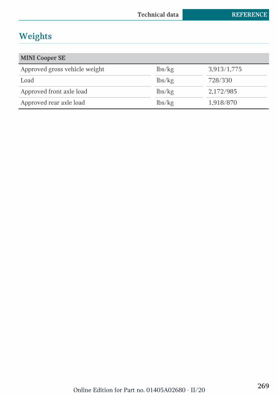
Weights
MINI Cooper SE
Approved gross vehicle weight lbs/kg 3,913/1,775
Load lbs/kg 728/330
Approved front axle load lbs/kg 2,172/985
Approved rear axle load lbs/kg 1,918/870
Seite 269
Technical data REFERENCE
269Online Edition for Part no. 01405A02680 - II/20
Appendix
Any updates to the Owner's Manual of thevehicle are listed here.
Updates made after the edito-rial deadline
The following chapters were updated in theprinted version of the Owner's Manual afterthe editorial deadline for the IntegratedOwner's Manual in the vehicle had closed:
– Notes: notes: own safety: maintenance.
– Driving tips: observe when driving: driv-ing on a race track.
– Mobility: engine oil: topping up the en-gine oil.
– Mobility: preventive maintenance: MINImaintenance system.
– Mobility: preventive maintenance: Con-dition Based Service CBS.
– Mobility: preventive maintenance: Main-tenance Manual and Service and War-ranty Information Booklet for US modelsand Warranty and Service Guide Bookletfor Canadian models.
Seite 270
REFERENCE Appendix
270Online Edition for Part no. 01405A02680 - II/20

Seite 271
Appendix REFERENCE
271Online Edition for Part no. 01405A02680 - II/20
Everything from A to Z
Index
A
ABS Antilock Braking System 162 Accelerator pedal positions 105 Accessories and parts 8 Accident, what to do 261 Acoustic Pedestrian Protection 106 AC quick charging cable, see Level 2 charg-
ing cable 220 Activated-charcoal filter 184 Active Guard, see Intelligent Safety 152 Active Voice Recognition 44 Adjusting menu contents, Central Informa-
tion Display (CID) 40 Adjustments, steering wheel 94 Advance climate control, see Stationary cli-
mate control 184 Airbags 141 Airbags, indicator and warning light 143 Air circulation, see Recirculated-air
mode 183 Air conditioning, climate 182 Air distribution, manual 183 Air drying, see Air conditioning 182 Air flow, automatic climate control 183 Air pressure, tires 227 Air vents, see Ventilation 184 Alarm system 79 Alarm triggering 79 Alarm, unintentional 80 All-season tires, see Winter tires 233 Amazon Alexa Car Integration 46 Antifreeze, washer fluid 117 Antilock Braking System ABS 162 Anti-slip control, see DSC 162 Approach control warning with city light
braking function 153 Approved axle load 269 Apps, see Owner's Handbook for Naviga-
tion, Entertainment, Communication 6
Arrival time 130 Artificial engine noise, see Acoustic Pedes-
trian Protection 106 Ash tray 192 Assistance when driving off 165 Assistance with breakdown 256 Audio, see Owner's Manual for Navigation,
Entertainment and Communication 6 AUTO intensity 183 Automatic climate control 181 Automatic Curb Monitor, exterior mir-
ror 93 Automatic deactivation, front-seat passen-
ger airbags 143 Automatic deactivation of the high-voltage
system 65 Automatic headlight control 136 Automatic locking 78 Automatic unlocking 78 Automatic vehicle wash 263 AUTO program, automatic climate con-
trol 182 AUTO program, intensity 183 Auto washing 262 Average consumption 129 Average speed 129 Axle loads, weights 269
B
Backrest curvature, see Lumbar support 86 Backrest, seats 85 Band-aids, see First-aid kit 256 Battery, charge state indicator 120 Battery, disposing of 255 Battery, vehicle 254 Being towed, see Towing 259 Belts, safety belts 87 Beverage holder, cup holder 200 Bluetooth connection 53
Seite 272
REFERENCE Everything from A to Z
272Online Edition for Part no. 01405A02680 - II/20
Bottle holder, see Cup holder 200 Brake assistant 162 Brake discs, break-in 208 Brake pads, break-in 208 Braking, information 209 Breakdown assistance 256 Breakdown, Flat Tire Monitor TPM 150 Breaking in 208 Break recommendation, see Fatigue
alert 159 Brightness of Control Display 50 Bulb replacement 251 Bulb replacement, front 252 Bulb replacement, rear 252 Bulb replacement, side 253 Bulbs and lights 251 Button, SOS 257 Button, Start/Stop 100 Bypassing, see Jump-starting 258
C
California Proposition 65 Warning 9 Camera-based assistance systems, see Intel-
ligent Safety 152 Camera lenses, care 266 Camera, rearview camera 173 Can holder, see Cup holder 200 Care, displays 266 Care, light-alloy wheels 264 Care, vehicle 263 Care, washing the vehicle 262 Cargo area 201 Cargo area, adapting size 205 Cargo area, enlarging 203 Cargo area lid 74 Cargo area, loading 201 Cargo area, storage compartments 203 Cargo cover 202 Cargo position, rear seat backrest 203 Cargo, stowing and securing 201 Cargo straps 202 Carpet, care 265 CBS Condition Based Service 248 Cell phone, see Owner's Manual for Naviga-
tion, Entertainment and Communication 6
Center armrest 199 Center console 34 Central Information Display (CID) 36 Central Information Display (CID), see Con-
trol Display 38 Central instrument cluster, LED ring 131 Central locking system, unlocking, from in-
side 71 Central screen, see Control Display 38 Changes, technical, see For Your Own
Safety 8 Changing parts 250 Changing wheels 238 Changing, wheels and tires 231 Charge state indicator of the high-voltage
battery 120 Charging battery, see Vehicle charging 218 Charging cable, storing, see Storage 221 Charging screen 119 Charging, see Charging the vehicle 218 Charging, see Vehicle charging 218 Charging status, see Display of the charging
status 223 Charging the vehicle 218 Charging the vehicle, see Vehicle charg-
ing 218 Charging tray for smartphones, see Wire-
less charging tray 194 Chassis number, see Vehicle identification
number 13 Check Control 121 Children, seating position 95 Children, transporting safely 95 Child restraint system 95 Child restraint system LATCH 98 Child restraint systems, mounting 96 Child seat, mounting 96 Child seats 95 Chrome parts, care 265 Cigarette lighter 192 Cleaning, displays 266 Clearance, water 209 Climate control 181 Clothes hooks 200 Coasting 106 Combination switch, see Turn signals 109
Seite 273
Everything from A to Z REFERENCE
273Online Edition for Part no. 01405A02680 - II/20

Combi switch, see Wiper system 109, 113 Comfort Access 72 Comfort entry 67 Compartments in the doors 199 Compass 190 Compatible devices, see Suitable devi-
ces 53 Compressor 234 Computer, see Onboard Computer 129 Condensation on windows 184 Condensation under the vehicle 210 Condition Based Service CBS 248 Configuring driving program 165 Confirmation signal 79 Connecting device 52 Connecting electrical devices, see Sock-
ets 193 Connections 52 Consumption, see Average consump-
tion 129 Contacts, see Owner's Handbook for Naviga-
tion, Entertainment, Communication 6 Contact with water, high-voltage system 65 Continued driving with a flat tire 148, 151 Control Display 38 Controller 38 Control systems, driving stability 162 Convenient closing 68 Convenient opening 67 Coolant 246 Cooling, maximum 182 Cooling system 246 Cornering light 137 Corrosion on brake discs 210 Cosmetic mirror 192 Coupling, see Pairing 52 Courtesy lights during unlocking 67 Courtesy lights with the vehicle locked 68 Cruise control 167 Cruise control without distance control, see
Cruise control 167 Cup holder 200 Customer service, see Owner's Manual for
Navigation, Entertainment, Communica-tion 6
D
Damage, tires 231 Dashboard 192 Data memory 10 Data protection, settings 51 Data, technical 268 Date 49 Date, display 125 Daytime pedestrian collision mitiga-
tion 157 Daytime running lights 137 DCC, see Cruise control 167 Decorative trim 192 Defrosting, see Windows, defrosting 184 Deleting personal data 51 Deletion of personal data 51 Departure times, stationary climate con-
trol 185 Destination distance 130 Device list 52 Digital clock 125 Digital compass 190 Dimensions 268 Dimmable exterior mirrors 92 Dimmable interior mirror 93 Direction indicator, see Turn signals 109 Display, date 125 Display, electronic, instrument cluster 119 Display for performance and energy recov-
ery 120 Display, GREEN Mode 214 Display, iDrive 36 Display lighting, see Instrument light-
ing 139 Displays 118 Displays, care 266 Displays, eDRIVE system 120 Displays, high-voltage system 120 Disposal, coolant 247 Disposal, vehicle battery 255 Distance control, see PDC 169 Distance to destination 130 Divided screen view, split screen 37 Drive display 120 Drive-off assistant 165
Seite 274
REFERENCE Everything from A to Z
274Online Edition for Part no. 01405A02680 - II/20
Drive-off assistant, see DSC 162 Driver assistance, see Intelligent
Safety 152 Drive-ready state in detail 101 Drive-ready state, switching off 104 Drive-ready state, switching on 101 Driver Fatigue Detector 159 Driver profiles 75 Driver profiles, exporting profiles 77 Driver profiles, importing profiles 77 Driving Dynamics Control, see MINI Driv-
ing Modes switch 164 Driving in detail 104 Driving instructions, breaking in 208 Driving instructions, eDRIVE drive sys-
tem 213 Driving mode, GREEN 214 Driving mode, GREEN Driving style analy-
sis 216 Driving modes 164 Driving notes, general 208 Driving notes, things to remember when
driving 208 Driving on racetracks 211 Driving, see Drive-ready state in detail 101 Driving stability control systems 162 Driving, Start/Stop button 100 Driving style analysis 216 Driving through water 209 Driving tip, GREEN tip 215 Driving tips 208 DSC Dynamic Stability Control 162 DTC Dynamic Traction Control 163 DVD, video, see Owner's Handbook for Nav-
igation, Entertainment, Communication 6 Dynamic Stability Control DSC 162 Dynamic Traction Control DTC 163
E
eDRIVE drive system, driving instruc-tions 213
eDRIVE, electric driving, see MINIeDRIVE 62
eDrive system, at a glance 0 eDRIVE system, displays 120
Electric driving 104 Electric driving, see MINI eDRIVE 62 Electric range 125 Electronic displays, instrument cluster 119 Electronic Stability Program ESP, see
DSC 162 E-mail, see Owner's Handbook for Naviga-
tion, Entertainment, Communication 6 Emergency Request 257 Emergency service, see MINI Roadside As-
sistance 256 Emergency unlocking, transmission
lock 104 Energy recovery, button 106 Energy recovery, displaying 120 Energy recovery, driving stability control
systems 162 Engine compartment 243 Engine compartment, working in 244 Engine noise, artificial, see Acoustic Pedes-
trian Protection 106 Entering a destination, see Owner's Hand-
book for Navigation, Entertainment, Com-munication 6
Entering an address, navigation, see Own-er's Manual for Navigation, Entertainmentand Communication 6
Entering a vehicle wash 263 Entertainment, see Owner's Manual for Nav-
igation, Entertainment and Communica-tion 6
Equipment, interior 187 Error displays, see Check Control 121 ESP Electronic Stability Program, see
DSC 162 Exchanging, wheels and tires 231 Exiting a vehicle wash 263 Exterior mirror, Automatic Curb Moni-
tor 93 Exterior mirror, automatic dimming fea-
ture 92 Exterior mirrors 92 Exterior mirrors, malfunction 92 External temperature display 125 External temperature warning 125 Eyes for securing cargo 202
Seite 275
Everything from A to Z REFERENCE
275Online Edition for Part no. 01405A02680 - II/20
F
Failure message, see Check Control 121 False alarm, see Unintentional alarm 80 Fan, see Air flow 183 Fastening safety belts, see Safety belts 87 Fatigue alert 159 Filter, see Microfilter/activated-charcoal fil-
ter 184 Fine wood, care 265 First-aid kit 256 Fish, MINIMALISM display 216 Flat tire, changing wheels 238 Flat Tire Monitor TPM 150 Flat tire, repairing 234 Flat tire, Tire Pressure Monitor TPM 145 Flat tire, warning light 146, 150 Flooding, driving through 209 Floor carpet, care 265 Floor mats, care 265 Fold-away position, windshield wip-
ers 112, 116 Foot brake 209 For Your Own Safety 8 Front airbags 141 Front fog lights 138 Front fog lights, LED, bulb replace-
ment 252 Front-seat passenger airbags, automatic de-
activation 143 Front-seat passenger airbags, indicator
light 144 Front seats 85 Fuse 255
G
Garage door opener, see Integrated Univer-sal Remote Control 187
General driving notes 208 General settings 48 Glare shield 192 Glass sunroof, initialize the system 84 Glass sunroof, see Panoramic glass sun-
roof 82
Glove compartment 198 GPS geolocation, vehicle position 49 GPS, navigation, see Owner's Handbook for
Navigation, Entertainment, Communica-tion 6
GREEN+ - program, driving dynamics 165 GREEN Mode 214 GREEN - program, driving dynamics 164 GREEN tip, driving tip 215 Gross vehicle weight, approved 269 Ground clearance 211
H
Handbrake, see Parking brake 107 Hand-held transmitter, alternating
code 188 Hands-free device, see Owner's Handbook
for Navigation, Entertainment, Communi-cation 6
Hazard warning flashers 256 Head airbag 142 Headlight control, automatic 136 Headlight flasher 109 Headlight glass 252 Headlights, care 263 Head restraints and seats 85 Head restraints, front 89 Head restraints, rear 90 Head-up Display 132 Head-up Display, standard view 132 Heavy cargo, stowing cargo 201 High-beam Assistant 137 High beams 109 High beams/low beams, see High-beam As-
sistant 137 High-voltage battery, charge state indica-
tor 120 High-voltage battery, discharge 214 High-voltage battery, heated 106 High-voltage battery, heavily dis-
charged 106 High-voltage system, automatic deactiva-
tion 65 High-voltage system, contact with water 65 High-voltage system, displays 120
Seite 276
REFERENCE Everything from A to Z
276Online Edition for Part no. 01405A02680 - II/20

High-voltage system, safety 65 High-voltage system, work 65 Hills 210 Hill start assistant, see Drive-off assis-
tant 165 Holder for beverages 200 HomeLink, see Integrated Universal Remote
Control 187 Homepage, see Internet 6 Hood 244 Horn 32 HUD Head-up Display 132 Hydroplaning 209
I
Ice warning, see External temperaturewarning 125
Icy roads, see External temperature warn-ing 125
Identification marks, tires 228 Identification number, see Vehicle identifi-
cation number 13 Illuminated ring, central instrument clus-
ter 131 Increasing the range 212 Indication of a flat tire 146, 150 Indicator and warning lights, see Check
Control 121 Indicator light, see Check Control 121 Individual air distribution 183 Individual settings, see Driver profiles 75 Inductive charging of a smartphone, see
Wireless charging tray 194 Inflation pressure, tires 227 Inflation pressure warning, tires 150 Information 6 Initialize, Tire Pressure Monitor TPM 146 Initializing, Flat Tire Monitor FTM 150 Input, iDrive 36 Instrument cluster 118 Instrument cluster, electronic displays 119 Instrument lighting 139 Integrated key 70 Integrated Owner's Manual in the vehi-
cle 60
Integrated Universal Remote Control 187 Intelligent emergency call 257 Intelligent Safety 152 Intended use 8 Intensity, AUTO program 183 Interior equipment 187 Interior lights 139 Interior lights during unlocking 67 Interior lights with the vehicle locked 68 Interior mirror 92 Interior mirror, automatic dimming fea-
ture 93 Interior mirror, compass 190 Interior mirror, manually dimmable 93 Interior motion sensor 80 Internet site 6 Interval display, service notifications 126 Interval mode 110, 114 In the vicinity of the center console 34 In the vicinity of the roofliner 35 In the vicinity of the steering wheel 32 IOM, see Integrated Owner's Manual in the
vehicle 60
J
Jacking points for the vehicle jack 240 Jam protection system, glass sunroof 84 Jam protection system, windows 81 Jump-starting 258
K
Keyless Go, see Comfort Access 72 Key, see Integrated key 70 Key, see Vehicle key 66 Knee airbag 142
L
Label on recommended tires 232 Label, runflat tires 233 Language, set on Control Display 48 Lashing eyes 202 LATCH child restraint fixing system 98
Seite 277
Everything from A to Z REFERENCE
277Online Edition for Part no. 01405A02680 - II/20
Leather care 264 LED ring, central instrument cluster 131 LEDs, light-emitting diodes 251 Letters and numbers, entering 36 Level 1 charging 224 Level 1 charging cable 220 Level 2 charging cable 220 Light 135 Light-alloy wheels, care 264 Light-emitting diodes, LEDs 251 Lighter 192 Lighting 135 Light replacement 251 Light replacement, front 252 Light replacement, rear 252 Light replacement, side 253 Lights and bulbs 251 Light switch 135 List of all messages 50 Load 202 Loading 201 Loading position 203 Location, vehicle position 49 Locking, automatic 78 Locking, from inside 71 Locking, see Opening and Closing 66 Locking, settings 78 Longer idle phases 266 Long idle times, long-term vehicle stor-
age 266 Long-term vehicle storage 266 Low beams 135 Low beams, automatic, see High-beam As-
sistant 137 Lower back support, mechanical 86 Luggage rack, see Roof-mounted luggage
rack 211 Lumbar support, mechanical 86
M
Maintenance 248 Maintenance requirements 248 Maintenance, service notifications 126 Maintenance system, MINI 248 Make-up mirror 192
Malfunction displays, see Check Con-trol 121
Manual brake, see Parking brake 107 Manual control, air distribution 183 Manual control, air flow 183 Manual operation, PDC Park Distance Con-
trol 170 Manual operation, rearview camera 173 Manufacturer of the MINI 8 Map update, see Owner's Handbook for Nav-
igation, Entertainment, Communication 6 Matt paint, care 264 Maximum cooling 182 Maximum speed display, see Speed Limit
Info 127 Maximum speed, winter tires 233 Measuring units 49 Mechanical key 70 Media of the Owner's Manual 60 Medical kit 256 Menu in instrument cluster 128 Menus, Central Information Display
(CID) 40 Messages 50 Messages, see Check Control 121 Microfilter 184 MID - program, driving dynamics 164 MINI Connected, see Owner's Handbook for
Navigation, Entertainment, Communica-tion 6
MINI driving modes 164 MINI eDRIVE 0 MINI Electric Corona Spoke 2 Tone 231 MINI logo projection during unlocking 67 MINI maintenance system 248 MINIMALISM analyzer 216 MINIMALISM information 216 Minimum tread, tires 230 MINI Roadside Assistance 256 Mirrors 92 Mobile communication devices in the vehi-
cle 209 Mobile phone, connecting 52 Mobile phone, see Owner's Manual for Navi-
gation, Entertainment and Communica-tion 6
Seite 278
REFERENCE Everything from A to Z
278Online Edition for Part no. 01405A02680 - II/20
Mobile Service, see MINI Roadside Assis-tance 256
Mobility System 234 Modifications, technical, see For Your Own
Safety 8 Moisture in headlight 252 Monitor, see Control Display 38 Mounting of child restraint systems 96 MP3 player, see Owner's Manual for Naviga-
tion, Entertainment, Communication 6 Multifunction steering wheel, buttons 32 Multimedia, see Owner's Manual for Naviga-
tion, Entertainment and Communication 6
N
Navigation, see Owner's Manual for Naviga-tion, Entertainment and Communication 6
Neck restraints, front, see Head restraintsfront 89
Neck restraints, rear, see Head restraintsrear 90
Neutral cleaner, see Light-alloy rims 264 New wheels and tires 231
O
OBD Onboard Diagnosis 249 Obstacle marking, rearview camera 174 Odometer 124 Onboard Computer 129 Onboard Diagnosis OBD 249 Onboard literature, printed 60 Onboard vehicle tool kit 250 On-call service, see MINI Roadside Assis-
tance 256 Opening and Closing 66 Opening, from inside 71 Operating concept Central Information Dis-
play (CID) operating concept 36 Operating menus, Central Information Dis-
play (CID) 36 Operation via the Controller 40 Operation via touchscreen 41 Optional equipment 7
Owner's Manual, printed 60
P
Paint, car care 264 Panic alarm, see Panic mode 80 Panic mode 80 Panoramic glass sunroof 82 Parallel parking assistant 175 Park Distance Control PDC 169 Parked vehicle, condensation 210 Parked vehicle ventilation, see Stationary
climate control 184 Parking aid, see PDC 169 Parking assistant 175 Parking brake 107 Parking lights 135 Parts and accessories 8 Passenger's side exterior mirror, tilt down,
see Automatic Curb Monitor 93 Pathway lighting 136 Pathway lines, rearview camera 174 PDC Park Distance Control 169 Pedestrian Protection, acoustic 106 Performance Control 164 Performance display 120 Personal profile, see Driver profiles 75 Phone, connecting 52 Plastic, care 265 PostCrash - iBrake 160 Power failure 255 Power windows 81 Pressure, tires 227 Pressure warning, tires 150 Printed onboard literature 60 Profiles, see Driver profiles 75 Programmable memory buttons, Central In-
formation Display (CID) 42 Protective function, glass sunroof 84 Protective function, windows 81 Push-and-turn reel, see Controller 38
Seite 279
Everything from A to Z REFERENCE
279Online Edition for Part no. 01405A02680 - II/20
Q
Quick charging cable, see Level 2 chargingcable 220
R
Racetrack operation 211 Radiator fluid 246 Radio, see Owner's Manual for Navigation,
Entertainment and Communication 6 Rain sensor 110, 114 Range 125 Ratchet straps 202 Rear lights 252 Rear seat backrests, folding down 203 Rearview camera 172 Rear-view mirrors, exterior 92 Rear window defroster 184 Rear window wiper, operation 112, 115 Recirculated-air filter 184 Recirculated-air mode 183 Recommended tire brands 232 Recuperation, button 106 Remaining range 125 Remote control, universal 187 Remote services, app, see Owner's Hand-
book for Navigation, Entertainment, Com-munication 6
Replacing parts 250 Replacing the battery, vehicle key 69 Replacing, wheels and tires 231 Reporting safety malfunctions 13 RES CNCL button, Cruise Control 167 Reserve warning, see Range 125 Reset, Tire Pressure Monitor TPM 146 Retreaded tires 232 Roadside parking lights 136 Rolling code hand-held transmitter 188 Roofliner 35 Roof-mounted luggage rack 211 Route, navigation, see Owner's Handbook
for Navigation, Entertainment, Communi-cation 6
RSC Runflat System Component, see Runflattires 233
RTTI, see Owner's Handbook for Naviga-tion, Entertainment, Communication 6
Rubber components, care 265 Runflat tires 233
S
Safe braking 209 Safety belt reminder for driver's seat and
front passenger seat 89 Safety belt reminder for the rear seats 89 Safety belts 87 Safety belts, care 265 Safety of the high-voltage system 65 Safety systems, airbags 141 Screens, care 266 Screen, see Control Display 38 Screwdriver 250 Sealant, see Mobility System 234 Search for charging stations, see Owner's
Manual for Navigation, Entertainment,Communication 6
Seat heating, front 87 Seating position for children 95 Seats and head restraints 85 Seats, front 85 Securing cargo 201 Selection list in instrument cluster 128 Sensors, care 266 Service and warranty 9 Service Center, see MINI Roadside Assis-
tance 256 Service notifications, display 126 Service requirements, Condition Based
Service CBS 248 Servotronic 165 SET button, Cruise Control 167 Settings, general 48 Settings, locking/unlocking 78 Settings, mirrors 92 Settings, seats and head restraints 85 Side airbag 141 Signaling, horn 32 Signals when unlocking 79
Seite 280
REFERENCE Everything from A to Z
280Online Edition for Part no. 01405A02680 - II/20

Sitting safely 85 Sizes, see Dimensions 268 Slide/tilt glass roof 82 Smartphone, connecting 52 Smartphone, see Owner's Manual for Navi-
gation, Entertainment and Communica-tion 6
Snow chains 238 Socket, OBD Onboard Diagnosis 249 Sockets, electrical devices 193 Software update 58 SOS button 257 Sound output, see Owner's Handbook for
Navigation, Entertainment, Communica-tion 6
Speed, average 129 Speed limit display, see Speed Limit
Info 127 Speed Limit Info 127 Speed warning 130 Split screen 37 SPORT program, driving dynamics 165 Stability control systems 162 Standard charging cable, see Level 1 charg-
ing cable 220 Standard charging, see Level 1 charg-
ing 224 Standard equipment 7 Standard view, Head-up Display 132 Standby state 100 Stars, MINIMALISM display 216 Start/Stop button 100 Stationary climate control 184 Stations, AM/FM, see Owner's Handbook
for Navigation, Entertainment, Communi-cation 6
Status control display, tires 145 Status information, Central Information Dis-
play (CID) 37 Status of Owner's Manual 7 Status, vehicle 134 Steering assistance 165 Steering column adjustment 94 Steering wheel, adjusting 94 Stop function in stationary vehicle 108 Storage, charging cable 221
Storage compartments 198 Storage, tires 233 Storing the vehicle 266 Stowing and securing cargo 201 Suitable devices 53 Suitable mobile phones 53 Summer tires, tread 230 Sun visor 192 Supplementary Owner's Manuals 60 Supplementary text message 124 Switch for driving dynamics 164 Switching off, drive-ready state 104 Switching on, drive-ready state 101 Switch, see Cockpit 32 Symbols 6
T
Tailgate 74 Tailgate via vehicle key 68 Tail lights 252 Technical changes, see For Your Own
Safety 8 Technical data 268 Telephone, see Owner's Manual for Naviga-
tion, Entertainment and Communication 6 Teleservices, see Owner's Handbook for
Navigation, Entertainment, Communica-tion 6
Temperature, automatic climate con-trol 181
Temperature display for external tempera-ture 125
Text message, see Check Control mes-sages 124
Theft alarm system, see Alarm system 79 Thigh support 86 Tilt alarm sensor 80 Tilt down, passenger's side exterior mirror,
see Automatic Curb Monitor 93 Time 48 Time of arrival 130 Tire damage 231 Tire identification marks 228 Tire inflation pressure 227
Seite 281
Everything from A to Z REFERENCE
281Online Edition for Part no. 01405A02680 - II/20

Tire inflation pressure monitoring, seeTPM 150
Tire pressure 227 Tire Pressure Monitor TPM 145 Tire repair kit, see Mobility System 234 Tires 227 Tires, changing 231 Tire sealant, see Mobility System 234 Tires, runflat 233 Tire tread 230 Tone, see Owner's Manual for Navigation,
Entertainment and Communication 6 Tools 250 Total vehicle weight 269 Touchscreen 41 Towing 259 TPM Flat Tire Monitor 150 TPM Tire Pressure Monitor 145 Traction control 163 TRACTION, see Dynamic Traction Control,
DTC 163 Traffic bulletins, see Owner's Handbook for
Navigation, Entertainment, Communica-tion 6
Transmission lock, electronic unlock-ing 104
Transporting children safely 95 Tread, tires 230 Trip computer 130 Triple turn signal activation 109 Trip odometer 124 Trip recorder, see Trip odometer 124 Trunk, see Cargo area 201 Turning radius lines, rearview camera 174 Turn signal, front 252 Turn signal, indicator light 123 Turn signal, side 253 Turn signals, operation 109 Turn signals, rear, bulb replacement 252
U
Unintentional alarm 80 Units, see Measuring units 49 Universal remote control 187 Unlocking, automatic 78
Unlocking, see Opening and Closing 66 Unlocking, settings 78 Updates made after the editorial deadline 7 Update, software 58 Updating software 58 Upholstery care 264 USB connection 55 USB port, position in vehicle 194 Used battery, disposing of 255 Use, intended 8 Using a smartphone via voice activation 46
V
Vanity mirror 192 Vehicle battery 254 Vehicle breakdown, see Breakdown assis-
tance 256 Vehicle, breaking in 208 Vehicle care 263 Vehicle care products 263 Vehicle features and options 7 Vehicle identification number 13 Vehicle jack 240 Vehicle key, additional 69 Vehicle key, loss 69 Vehicle key, malfunction 69 Vehicle key, opening/closing 66 Vehicle key, replacing the battery 69 Vehicle key, see Vehicle key 66 Vehicle paint, care 264 Vehicle position, vehicle location 49 Vehicle status 134 Vehicle wash 263 Vehicle wash, automatic 263 Vehicle, washing 262 Ventilation 184 Venting, see Stationary climate control 184 VIN, see Vehicle identification number 13 Voice activation 44 Voice command response 44 Voice recognition, see Active Voice Recog-
nition 44
Seite 282
REFERENCE Everything from A to Z
282Online Edition for Part no. 01405A02680 - II/20

W
Warning and indicator lights, see CheckControl 121
Warning displays, see Check Control 121 Warning messages, see Check Control 121 Warning triangle 256 Warranty 8 Washer fluid 117 Washer nozzles, windshield 112, 115 Washing the vehicle 262 Water, high-voltage system 65 Water on roads 209 Weights 269 Welcome lights 136 Welcome lights during unlocking 67 Wheel base, vehicle 268 Wheels 227 Wheels, changing 231 Wheels, Tire Pressure Monitor TPM 145 Windows, powered 81 Windshield cleaning system 109, 113 Windshield washer fluid 117 Windshield washer nozzles 112, 115 Windshield wipers, fold-away posi-
tion 112, 116 Windshield wipers, see Wiper sys-
tem 109, 113 Winter storage, care 266 Winter tires, suitable tires 233 Winter tires, tread 230 Wiper blades, replacing 250 Wiper fluid 117 Wiper system 109, 113 Wireless charging of a smartphone, see
Wireless charging tray 194 Wireless charging tray for smart-
phones 194 Wood, care 265 Word match concept, navigation 36 Work, high-voltage system 65 Wrench 250
Seite 283
Everything from A to Z REFERENCE
283Online Edition for Part no. 01405A02680 - II/20

01405A02680 ue
*BL5A0268000Z*
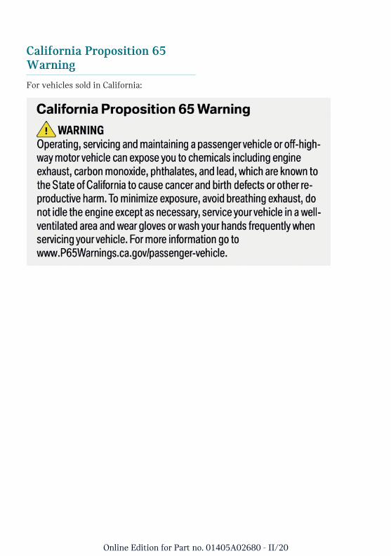
California Proposition 65Warning
For vehicles sold in California:
Online Edition for Part no. 01405A02680 - II/20

MINI MOTORER'S GUIDE APP.
Your customized information about the vehicle in an app.Optimized for smartphones & tablets. Can be used offline.
01405A02680 ue
*BL5A0268000Z*
Online Edition for Part no. 01405A02680 - II/20