mineman, volume 5 (mn 3 & 2) -...
TRANSCRIPT

DISTRIBUTION STATEMENT A: Approved for public release; distribution is unlimited.
NONRESIDENT
TRAINING COURSE
November 1994
Mineman, Volume 5 (MN 3 & 2)
NAVEDTRA 14158

DISTRIBUTION STATEMENT A: Approved for public release; distribution is unlimited.
Although the words �he,� �him,� and �his� are used sparingly in this course to enhance communication, they are not intended to be gender driven or to affront or discriminate against anyone.

i
PREFACE By enrolling in this self-study course, you have demonstrated a desire to improve yourself and the Navy. Remember, however, this self-study course is only one part of the total Navy training program. Practical experience, schools, selected reading, and your desire to succeed are also necessary to successfully round out a fully meaningful training program. COURSE OVERVIEW: In completing this nonresident training course, you will demonstrate a knowledge of exercise and training mines, including actuation, laying, handling, shop, hunting, and mechanical sweep mines.
THE COURSE: This self-study course is organized into subject matter areas, each containing learning objectives to help you determine what you should learn along with text and illustrations to help you understand the information. The subject matter reflects day-to-day requirements and experiences of personnel in the rating or skill area. It also reflects guidance provided by Enlisted Community Managers (ECMs) and other senior personnel, technical references, instructions, etc., and either the occupational or naval standards, which are listed in the Manual of Navy Enlisted Manpower Personnel Classifications and Occupational Standards, NAVPERS 18068. THE QUESTIONS: The questions that appear in this course are designed to help you understand the material in the text. VALUE: In completing this course, you will improve your military and professional knowledge. Importantly, it can also help you study for the Navy-wide advancement in rate examination. If you are studying and discover a reference in the text to another publication for further information, look it up.
1994 Edition Prepared by MNCM M.D. Femrite
Published by NAVAL EDUCATION AND TRAINING
PROFESSIONAL DEVELOPMENT AND TECHNOLOGY CENTER
NAVSUP Logistics Tracking Number 0504-LP-026-8120

ii
Sailor�s Creed
�I am a United States Sailor. I will support and defend the Constitution of the United States of America and I will obey the orders of those appointed over me. I represent the fighting spirit of the Navy and those who have gone before me to defend freedom and democracy around the world. I proudly serve my country�s Navy combat team with honor, courage and commitment. I am committed to excellence and the fair treatment of all.�

TABLE OF CONTENTS
Chapter Page
1 Introduction to Exercise and Training (ET) Mines . . . . . . . . . . . . . 1-1
2 Actuation Mines . . . . . . . . . . . . . . . . . . . . . . . . . . . . . . . . . 2-1
3 Laying, Handling, Shop, Hunting, and Mechanical Sweep Mines . . . 3-1
Appendix
I Glossary . . . . . . . . . . . . . . . . . . . . . . . . . . . . . . . . . . . . . . . AI-1
II Abbreviations and Acronyms . . . . . . . . . . . . . . . . . . . . . . . . . . AII-1
III References Used to Develop This TRAMAN . . . . . . . . . . . . . . . AIII-1
Index . . . . . . . . . . . . . . . . . . . . . . . . . . . . . . . . . . . . . . . . . . Index-1
. . .111
SUMMARY OF THEMINEMAN TRAINING SERIES
This series of training manuals was developed to replace the Mineman 3 & 2 and Mineman1 & C manuals. The content is directed toward personnel working toward advancement in theMineman rating.
The five volumes in this series are based on major topic areas with which the Minemanshould be familiar. Their topics include the following areas:
Volume 1: Mine warfare, operations, and organization.
Volume 2: Mine shop administration and supply.
Volume 3: Mine maintenance and explosive
Volume 4: Mines and mine components.
Volume 5: Exercise and training mines.
materials.
iv
v
INSTRUCTIONS FOR TAKING THE COURSE
ASSIGNMENTS The text pages that you are to study are listed at the beginning of each assignment. Study these pages carefully before attempting to answer the questions. Pay close attention to tables and illustrations and read the learning objectives. The learning objectives state what you should be able to do after studying the material. Answering the questions correctly helps you accomplish the objectives. SELECTING YOUR ANSWERS Read each question carefully, then select the BEST answer. You may refer freely to the text. The answers must be the result of your own work and decisions. You are prohibited from referring to or copying the answers of others and from giving answers to anyone else taking the course. SUBMITTING YOUR ASSIGNMENTS To have your assignments graded, you must be enrolled in the course with the Nonresident Training Course Administration Branch at the Naval Education and Training Professional Development and Technology Center (NETPDTC). Following enrollment, there are two ways of having your assignments graded: (1) use the Internet to submit your assignments as you complete them, or (2) send all the assignments at one time by mail to NETPDTC. Grading on the Internet: Advantages to Internet grading are: • you may submit your answers as soon as
you complete an assignment, and • you get your results faster; usually by the
next working day (approximately 24 hours). In addition to receiving grade results for each assignment, you will receive course completion confirmation once you have completed all the assignments. To submit your assignment answers via the Internet, go to:
http://courses.cnet.navy.mil
Grading by Mail: When you submit answer sheets by mail, send all of your assignments at one time. Do NOT submit individual answer sheets for grading. Mail all of your assignments in an envelope, which you either provide yourself or obtain from your nearest Educational Services Officer (ESO). Submit answer sheets to:
COMMANDING OFFICER NETPDTC N331 6490 SAUFLEY FIELD ROAD PENSACOLA FL 32559-5000
Answer Sheets: All courses include one “scannable” answer sheet for each assignment. These answer sheets are preprinted with your SSN, name, assignment number, and course number. Explanations for completing the answer sheets are on the answer sheet. Do not use answer sheet reproductions: Use only the original answer sheets that we provide—reproductions will not work with our scanning equipment and cannot be processed. Follow the instructions for marking your answers on the answer sheet. Be sure that blocks 1, 2, and 3 are filled in correctly. This information is necessary for your course to be properly processed and for you to receive credit for your work. COMPLETION TIME Courses must be completed within 12 months from the date of enrollment. This includes time required to resubmit failed assignments.

vi
PASS/FAIL ASSIGNMENT PROCEDURES If your overall course score is 3.2 or higher, you will pass the course and will not be required to resubmit assignments. Once your assignments have been graded you will receive course completion confirmation. If you receive less than a 3.2 on any assignment and your overall course score is below 3.2, you will be given the opportunity to resubmit failed assignments. You may resubmit failed assignments only once. Internet students will receive notification when they have failed an assignment--they may then resubmit failed assignments on the web site. Internet students may view and print results for failed assignments from the web site. Students who submit by mail will receive a failing result letter and a new answer sheet for resubmission of each failed assignment. COMPLETION CONFIRMATION After successfully completing this course, you will receive a letter of completion. ERRATA Errata are used to correct minor errors or delete obsolete information in a course. Errata may also be used to provide instructions to the student. If a course has an errata, it will be included as the first page(s) after the front cover. Errata for all courses can be accessed and viewed/downloaded at: http://www.advancement.cnet.navy.mil STUDENT FEEDBACK QUESTIONS We value your suggestions, questions, and criticisms on our courses. If you would like to communicate with us regarding this course, we encourage you, if possible, to use e-mail. If you write or fax, please use a copy of the Student Comment form that follows this page.
For subject matter questions: E-mail: [email protected] Phone: Comm: (850) 452-1548 DSN: 922-1548 FAX: (850) 452-1370 (Do not fax answer sheets.) Address: COMMANDING OFFICER NETPDTC N311 6490 SAUFLEY FIELD ROAD PENSACOLA FL 32509-5237 For enrollment, shipping, grading, or completion letter questions E-mail: [email protected] Phone: Toll Free: 877-264-8583 Comm: (850) 452-1511/1181/1859 DSN: 922-1511/1181/1859 FAX: (850) 452-1370 (Do not fax answer sheets.) Address: COMMANDING OFFICER NETPDTC N331 6490 SAUFLEY FIELD ROAD PENSACOLA FL 32559-5000 NAVAL RESERVE RETIREMENT CREDIT If you are a member of the Naval Reserve, you may earn retirement points for successfully completing this course, if authorized under current directives governing retirement of Naval Reserve personnel. For Naval Reserve retirement, this course is evaluated at 2 points. (Refer to Administrative Procedures for Naval Reservists on Inactive Duty, BUPERSINST 1001.39, for more information about retirement points.)

vii
Student Comments Course Title: Mineman, Volume 5 (MN 3 & 2)
NAVEDTRA: 14158 Date: We need some information about you: Rate/Rank and Name: SSN: Command/Unit Street Address: City: State/FPO: Zip Your comments, suggestions, etc.: Privacy Act Statement: Under authority of Title 5, USC 301, information regarding your military status is requested in processing your comments and in preparing a reply. This information will not be divulged without written authorization to anyone other than those within DOD for official use in determining performance. NETPDTC 1550/41 (Rev 4-00


CHAPTER 1
INTRODUCTIONTO
EXERCISE AND TRAINING (ET) MINES
LEARNING OBJECTIVE
Upon completing this chapter, you should be able to describe theExercise and Training Mine Material Program.
As a Mineman, you will, at some time duringyour career, work or come in contact with the Exer-cise and Training Mine Material Program. With to-day’s changing Navy, more and more emphasis isbeing placed on mine countermeasures and training.This means more mine exercises and more trainingin the assembly, delivery, and sweeping of mines.This chapter discusses the Exercise and TrainingMine Material Program and the responsibilities thatgo with running the program.
EXERCISE AND TRAININGMINE MATERIAL PROGRAM
The Exercise and Training (ET) Mine MaterialProgram replaces the Non-Service Mine Program.Established to support fleet training in all areas ofunderwater mine warfare, the ET program is con-cerned principally with making sure that material isavailable to fill the exercise and training require-ments of the fleet.
ET mines, for the most part, look and act liketheir service counterparts and provide activities withthe means to improve their mine assembly, delivery,and countermeasures capabilities. They use inert-loaded or empty mine cases; however, initiatingexplosive devices and pyrotechnics are contained insome mines to provide realism in mine delivery orfiring simulations and to aid in recovery operations.
1-1
PROGRAM RESPONSIBILITIES
The Commander, Mine Warfare Command(COMINEWARCOM) has directed the Commander,Mobile Mine Assembly Group (COMOMAG) tomonitor the use of ET assets and to submit aquarterly usage report to the fleet commanders-in-chief to assist in monitoring their non-combat ex-penditure allocation (NCEA). The NCEA for minesis issued by the Chief of Naval Operations (CNO)annually and is based on fleet requirements andasset availability. To ensure accurate reporting,Mobile Mine Assembly Group (MOMAG) activitiessupporting ET exercises report their ET mine usageto COMOMAG quarterly.
ET MINE BASIC ALLOWANCE
Exercise and Training (ET) Mine MaterialProgram, OPNAVINST 8550.9, establishes the basicallowances for ET mines. Information ConcerningMine Warfare Exercise and Training (ET) MaterialAllowance and Reporting Criteria, COMOMAG/MOMAGINST 8550.9, expands upon the allowancerequirement in OPNAVINST 8550.9 by establishingspecific ET allowances for MOMAG activities. Withthese two instructions, each activity is required tomaintain various ET mines and to develop andmaintain appropriate stocks of ET material used tosupport fleet training requirements.

Activities requiring the use of ET mines insupport of training requirements must submit arequest for the mines, via the appropriate chain ofcommand, to the nearest MOMAG activity thatstocks the mines and in accordance with Proceduresfor Requesting Mine Warfare Exercise and TrainingMaterial and Services, COMINEWARCOMINST8550.1. MOMAG activities receiving such requestsmust verify the availability of the requested assetsand respond accordingly.
RECORDS AND REPORTS
MOMAG activities involved in ET mineoperations are required to maintain records andsubmit appropriate reports. Several reports, readi-ness and operational, concerning the available assetsor operational performance of ET mines must besubmitted by MOMAG activities. The format andreporting requirements for these reports are tailoredto the types of mines employed in the mineexercises.
An ET mine case inventory report indicates anactivity’s capability to support the ET program. Thisreport is submitted in message format and in com-pliance with COMOMAG/MOMAGINST 8550.9.
A preliminary post-analysis report is required forexercises employing actuation mines and versatileexercise mines (VEMs). The preliminary messagereport must be submitted by MOMAG activitieswithin 48 hours after the mine recovery phase of anexercise. This report is intended to aid the officerconducting the exercise (OCE) with a quick-lookcritique of the counter-measures operation/exercise.An exercise operational report for actuation orlaying mines is also required in connection with thepreliminary post-analysis message report. Thecontents of the exercise opera-tional report willdepend on the type of ET mines used during theexercise. Mine Warfare Exercise and Training (ET)Post Exercise Reporting, COMOMAG/MOMAG-INST 8550.1, outlines the requirements and pro-cedures for preliminary and operational reports.
Final preparation teams will submit a situationreport upon arrival at supporting activities by usingenclosure (5) of Guidance for Personnel Assigned
in Support of Mine Warfare Exercise and Train-ing (ET) operations, COMOMAG/MOMAGINST3120.2, only if problems arise that might jeopardizethe success of the mission.
Trip reports will be submitted at the completionof an exercise and within 5 days upon return of theobserver or the final preparation team. A trip reportwill provide operational data to the commandingofficer or the officer-in-charge and will consist of asummary of events that occurred, problem areasencountered, and corrective actions taken during theoperation, as well as general comments and recom-mendations. Information concerning requirements,procedures, and format of trip reports are containedin COMOMAG/MOMAGINST 3120.2.
IN-WATER RELIABILITYEVALUATION MINE
Another means of evaluating the operationalreliability of the service stockpile is the in-waterreliability evaluation (IRE) mine. The IRE mine isidentical to its service mine counterpart, except thatit is assembled with an inert-loaded mine case anda minimum of explosive devices. Special instru-mentation such as a sonar transmitter (to easerecovery operations) and a time fire recorder (torecord time of actuation) are installed. IRE minesare assembled by using only serviceable (Code A)components, except for the mine case and the arm-ing device. (Explosive-loaded cases may be usedfor special test purposes.)
ET MINE TYPES
ET mine types are described in chapters 2 and 3of this volume, with the exception of the Mk 74Mod 0 versatile exercise mine (VEM). The VEM isused to assess the effectiveness of surface andairborne mine countermeasure systems (sweepingand hunting) and the tactics and techniquesemployed by those systems. The Mk 74 Mod 0VEM system is comprised of the versatile exercisemine, a mine actuation indicator, an over-the-sidetransducer, a mine programmer/analyzer, a datatransfer unit, a mine computer program, and specialtest and support equipment.
1-2

Figure 1-1.—System layout.
The system, shown in figure 1-1, can simulate AUTHORIZED CONFIGURATIONS,the actuation system of most known bottom mines. CONFIGURATION DATA,In addition to assessing the effectiveness of mine AND MAINTENANCEcountermeasures, the Mk 74 Mod 0 VEM can assistin the development of new mine sensors and mine Unlike their service counterparts, ET mines aresweeping tactics. NOT assembled and stored
assembly configurations (A,For further information concerning the VEM, mines may be assembled
refer to Versatile Exercise Mine Mk 74 Mod 0 figurations: all-up assembly(VEM); Description and Maintenance, NAVSEA
inB,inor
various degrees ofC, E, and F). ETone of two con-subassembly.
SW550-AE-MMI-070; and Versatile Exercise Mine . ALL-UP ASSEMBLY: The term all-upMk 74 Mod 0 (VEM), Organizational Level Pro- assembly is used to designate a completely as-cedures; Rigging, Deployment, and Recovery, sembled ET mine. Configuration data for all-upNAVSEA SW570-FO-MMO-050. assemblies are contained in the appropriate ET mine
1-3

assembly manuals, which list the assembly-levelitems required for all authorized operational assem-blies (OAs).
l SUBASSEMBLY: The term subassembly isused to designate an ET mine storage and shippingconfiguration, which commanding officers orofficers-in-charge may elect to use at their option.
The maintenance policy for service mines im-poses programmed maintenance on assembled mineconfigurations to ensure mine readiness. The main-tenance policy for ET mines imposes maintenanceonly on assembly-level items to make sure that in-termediate mine assembly activities can expedi-tiously support fleet training requirements.
Unlike service mines, maintenance on ET minematerial is performed only when necessary or afteran ET mine is recovered. Since MOMAG activitieshave custody of all ET material, they are responsiblefor all aspects of maintenance, except maintenanceon handling mines.
When an activity other than a MOMAG activityhas subcustody of handling mines, that activity isresponsible for all minor maintenance of the mines.However, major maintenance or refurbishment mustbe performed by the MOMAG activity havingcustody of the mines. Refurbish-merit is the processby which assembly-level items are restored toacceptable operational conditions after they havebeen used in a mine exercise.
1-4

RECOMMENDED READING LIST
NOTE: Although the following references were current when this TRAMAN waspublished, their continued currency cannot be assured. Therefore, you need to ensure thatyou are studying the latest revision.
Exercise and Training (ET) Mine Material Program, OPNAVINST 8550.9, Chief of Naval Operations, Wash-ington, D.C., 1989.
Guidance for Personnel Assigned in Support of Mine Warfare Exercise and Training (ET) Operations,COMOMAG/MOMAGINST 3120.2, Mobile Mine Assembly Group, Charleston, S.C., 1987.
Information Concerning Mine Warfare Exercise and Training (ET) Material Allowance and Reporting Criteria,COMOMAG/MOMAGINST 8550.9, Mobile Mine Assembly Group, Charleston S.C., 1994.
Mine Warfare Exercise and Training (ET) Material Maintenance and Refurbishment, C O M O M A G /MOMAGINST 8550.14, Mobile Mine Assembly Group, Charleston, S.C., 1993.
Mine Warfare Exercise and Training (ET) Post Exercise Reporting, COMOMAG/MOMAGINST 8550.1, MobileMine Assembly Group, Charleston, S.C., 1988.
Procedures for Requesting Mine Warfare Exercise and Training Material and Services, COMINEWARCOM-INST 8550.1, Mine Warfare Command, Corpus Christi, Tex., 1992.
Versatile Exercise Mine Mk 74 Mod 0 (VEM), Description and Maintenance, NAVSEA SW550-AE-MMI-070,Naval Sea Systems Command, Washington, D.C., 1993.
Versatile Exercise Mine Mk 74 Mod 0 (VEM), Organizational Level Procedures Rigging, Deployment, andRecovery, NAVSEA SW570-FO-MMO-050, Naval Sea Systems Comnmand, Washington, D.C., 1990.
1-5


CHAPTER 2
ACTUATION MINES
LEARNING OBJECTIVES
Upon completing this chapter, you should be able to do the following:
1. Describe the Mk 52 and Mk 55 actuation mines.
2. Describe the detection system employed in the actuation mines.
3. Describe the different operational assemblies of the Mk 52 and Mk 55actuation mines.
4. Identify the proper planting depths for the Mk 52 and Mk 55 actuationmines.
5. Describe the operational description of the Mk 52 and Mk 55 actuationmines.
6. Describe the various mine components used to assemble the Mk 52 andMk 55 actuation mines.
Exercise and training (ET) mines, for the most Designed for testing mine countermeasurespart, look and act like their service counterparts. ETmines provide activities with the means to improvetheir mine assembly, delivery, and countermeasurescapabilities. Actuation mines are one type of ETmines, used primarily to support the total weaponconcept training in exercises and in war games atsea.
equipment and for training countermeasures person-nel, actuation mines contain sensing and actuationsystems identical to those in service mines butwhich, instead of exploding the mine, operate acces-sories that provide for visual indication of mineactuation, and for self-locating and recovery withoutrecourse to divers. The different types of actuationmines are discussed in this section.
ACTUATION MINE TYPESFLIGHT ACTUATION MINE
Actuation mines are reusable configurations thatare used primarily for training exercises, using aninert-loaded mine case and small explosive devicesand/or pyrotechnics that are contained in the minesto provide a realism in mine delivery, for firingsimulation, and as an aid in recovery operations.They provide target response characteristics identicalto those of service mines of equal Mark and Mod.
The flight actuation mine is identical to the air-laid service mines of like Mark and Mod with theadditional externally attached float. The mine con-sists of an inert-loaded standard mine case contain-ing service mine detection components, firing as-semblies, and safety devices. The float releases asmoke signal when actuated and surfaces itself at a
2-1

preset time to allow mine location and recovery.Actuation mines use a sonar transmitter to aid in thelocation for recovery.
NONFLIGHT ACTUATION MINE
The nonflight actuation mine is identical to theflight actuation mine except that it does not useflight gear and is planted by surface craft.
MK 52 MODS 2 AND 5 ACTUATION MINES
Mk 52 Mods 2 and 5 actuation mines, shown infigure 2-1, are 1,000-pound, aircraft-laid, bottom,inert-loaded mines. Each Mod employs one or moredetectors that respond to acoustic or magnetic in-fluence fields of a passing ship. The Mk 52 Mod 2mine employs a magnetic detection system, and theMk 52 Mod 5 employs a combination of acoustic/magnetic detection systems.
The same structural, planting, arming, and deto-nating components are used in each Mod, with the
basic difference among Mods being the type ofdetector or the combination of detectors used.
The mine consists of an inert-loaded mine case,tiring assembly and safety devices. and an externaldrill section attached to the tail of the mine case.The mine case is loaded with cement or a similarinert substance in place of the service mine’s explo-sive main charge and does not incorporate explo-sives in the arming device.
Instead, the firing current (which initiates suchexplosives in the service mine) in the actuation mineactuates a pyrotechnic signal that surfaces to indi-cate mine actuation. The tail cover of the mine
provides a watertight passage for the electric cablethat carries the firing current that ejects the signal.A float shield on the tail of the mine houses a drillfloat that contains the signal. At a preset time, thefloat itself is freed to rise to the surface, paying outrecovery line as it rises. Thus, it provides visuallocation of the mine with a line made fast to themine, and enables its recovery by surface craft.
Figure 2-1.—Mk 52 actuation mine.
2-2
Figure 2-2.—Mk 55 actuation mine.
MK 55 MODS 2 AND 5 ACTUATION MINES
The Mk 55 Mods 2 and 5 actuation mines,shown in figure 2-2, are 2,000-pound, aircraft-laid,bottom, inert-loaded mines. The Mk 55 actuationmine is identical to the Mk 52 except that the Mk55 is larger.
DETECTION SYSTEMS
The Mk 52 and Mk 55 actuation mines employtwo detection systems. Each of the mines can be as-sembled with either magnetic (Mod 2) or acoustic/magnetic (Mod 5) detection systems.
MOD 2 DETECTION SYSTEM
The Mk 20 Mod 1 firing mechanism, shown infigure 2-3, is used in the Mk 52 and Mk 55 Mod 2actuation mines. The Mk 20 is a magnetic-influencemechanism housed in a red aluminum case 4 1/2inches high, 6 inches long, and 5 1/2 inches wide.
Externally, it has two screwdriver-operated con-trols (balance and sensitivity) and three connectors.The J401 and J402 connectors connect the mech-
anism to the other mine components. The J403 con-nector accommodates an attenuator plug. Theattenuator plug (a separate component) receives thesignal from the mine’s search coil and reduces thestrength of the signal going to the firing mechanismamplifier so that the mechanism does not producelooks when a small vessel passes nearby or when atarget passes at a distance beyond the effective rangeof the mine. This reduces the chance that a minefiring will be wasted. Any one of the six differentattenuator plugs can be used to produce differentamounts of attenuation, ranging from no attenuationwith a No. 1 plug to the maximum attenuation witha No. 6 plug. Attenuator plugs are not furnishedwith the Mk 20 firing mechanism, but one must beinstalled or the mechanism will not operate.
Internally, the mechanism consists of anamplifier and a look relay. The amplifier, whichincreases the strength of the input signal to close thelook relay, has two main parts: an oscillator and abridge network. The oscillator converts direct cur-rent from a battery in the mine into 115 Hz. Thisalternating current powers the bridge network. Thebridge network is a circuit that permits the smallsignal received from the search coil (through the
2-3
attenuator plug) to control the large signal producedby the oscillator. In this way, a signal is producedthat is strong enough to operate the look relay. Theoscillator signal is put onto and removed from bothsides of the bridge at exactly the same time;therefore, the bridge stays balanced. The bridgebecomes unbalanced when a ship’s magnetic fieldcauses the search coil to send a signal to the bridgeand is subtracted from the oscillator signal on theother side. This causes the bridge to be unbalanced.The larger the signal from the search coil, the moreunbalanced the bridge becomes. When the bridge isbalanced, no signal is sent to the look relay. But,when the bridge becomes unbalanced, a part of theoscillator signal is fed into the look relay. The moreunbalanced the bridge becomes, the larger theoscillator signal that is applied to the look relay. Inthis way, the comparatively small signal from thesearch coil controls the amplitude of the large signalfrom the oscillator that is fed into the look relay.
look.” When the magnetic field near the mine startsto decrease, the current from the search reverses.
When this happens, the bridge is unbalanced inthe opposite direction and the signal from theamplifier reverses. This causes the look-relay needleto move in the opposite direction. When it movesfar enough, it touches a second electrical contact anda reverse look is taken. Both the initial look and thereverse look are required for an actuation countto fire the mine.
The Mk 20 firing mechanism’s operation isfollows:
or
as
1. A change in the magnetic field at the minecauses a small search-coil current.
2. The attenuator plug reduces the current toone that will actuate the firing mechanism only ifthe ship is of the desired class and is within damageradius.
3. The amplitude of a weak signal from the
Figure 2-3.—Mk 20 Mod 1 firing mechanism.
The look relay is a switch that operates like anelectrical meter in that it has a needle that is movedby an input. In this case, the input is from theamplifier. If the input from the amplifier is strongenough, it moves the needle far enough to cause itto touch an electrical contact. When this occurs, theswitch closes and the firing mechanism “takes a
attenuator is increased by the mechanism amplifieruntil it is strong enough to operate the look relay.
4. The look relay closes one of its two sets ofcontacts.
5. Asbegins todirection.
the strength of the ship’s magnetic fielddecrease, the search coil current reverses
6. The attenuator plug reduces the reversecurrent to the amplitude that will actuate the firingmechanism only if the ship is of the desired classand is within damage radius. The look relay receivesa second current, which closes the second set ofcontacts.
7. The mine detonates (or counts an actuation)unless more than one firing mechanism is used inthe mine; in which case, the mine may not be readyto detonate or to count an actuation. Under theseconditions, when the look relay of the Mk 20 firingmechanism closes for the reverse look, the circuitthat causedactuation is
2-4
the mine to detonate or to count anonly partially completed. The look

relays in all other firing mechanisms in the minemust also be closed to complete the circuit.
MOD 5 DETECTION SYSTEM
The Mk 21 Mod 0 firing mechanism, shown infigure 2-4 and used with the Mk 20 Mod 1 firingmechanism, is an acoustic detecting device used inthe Mk 52 and Mk 55 Mod 5 actuation mines. Themechanism is housed in a blue aluminum casemeasuring 5 inches high, 6 inches long, and 3 incheswide. Externally, the mechanism has two male andtwo female connectors and a screwdriver-operatedswitch (S301).
Figure 2-4.—Mk 21 Mod 0 firing mechanism.
The Mk 21 firing mechanism uses two othercomponents: the Mk 3 Mod 0 depth compensatorand the Mk 6 Mod 1 hydrophone. They are installedin the tail cover and are connected by a cableassembly.
Mk 3 Mod 0 Depth Compensator
The Mk 3 Mod 0 depth compensator, shown infigure 2-5, is used in the Mk 52 and Mk 55 Mod 5actuation mines. It is a hydrostatically operated,electromechanical switching device that automati-cally adjusts the sensitivity of certain firing mech-anisms by changing resistances in the detectingcircuit. The compensator consists of a frame-and-bellows assembly, a switch-bracket assembly, a leverarm assembly, a stud (inlet port), a housing (castiron), and associated electrical components.
Figure 2-5.—Mk 3 Mod 0 depth compensator.
Mk 6 Mod 1 Hydrophone
The Mk 6 Mod I hydrophone, shown in figure2-6, is connected to the Mk 21 firing mechanism bya cable assembly.
Because of the classification of the Mk 21 firingmechanism and the Mk 6 hydrophone, for furtherinformation, refer to Mine Components D throughF; Description and Class-B Criteria, N A V S E ASW550-AA-MMI-020; and Mine Components Gthrough W; Description and Class-B Criteria,NAVSEA SW550-AA-MMI-030.
2-5
Figure 2-6.—Mk 6 Mod 1 hydrophone.
OPERATIONAL ASSEMBLIES
Whereas the Mark designation of a mine is gen-erally distinguished by the differences in the shapeof the mine case and the Mod by the difference inthe firing mechanisms, the operational assemblies(OAs) denote differences in the use of flight gear. Inpractice. the OA to be assembled is chosen by theassembly activity, according to the planting agent,personnel, and conditions under which the mineswill be planted. That OA is then specified in as-sembly orders that are issued to the mine assemblyactivity in support of the mission plans.
AUTHORIZED CONFIGURATION DATA
Actuation mines may be assembled to either oneof two configurations: an all-up assemby, or a sub-assembly. They are discussed in chapter 1 of thisvolume.
OAs for Mk 52 and Mk 55 actuation mines can befound in Mines, Underwater: Actuation, Description,Assembly, and Tests, NAVSEA SW550-AE-MMI-040.
PLANTING DEPTHS
The water depth in which an actuation mine canbe planted is determined by the depth that thesignaling gear will operate and the depth at whichthe mine can be recovered without the use of divers.Bottom conditions are also a factor in determiningthis depth. If the water is less than 40 feet, thebottom must be hard or have less than 1 foot ofsediment or the signaling and recovery gear may failto operate. Even in greater water depths, the maxi-mum sediment depth on the bottom must be lessthan 4 feet if the gear is expected to operatereliably.
AUTHORIZED OPERATIONAL ASSEMBLIES The minimum planting depth for the Mk 52actuation mine is 25 feet, and the minimum planting
Variations in the use of assembly-level items depth for the Mk 55 actuation mine is 30 feet. Ifwithin an authorized mine configuration are called these mines are to be recovered without divers, theyoperational assemblies (OAs). An abbreviated list have a fixed maximum water depth of 200 feet.showing components that distinguish the authorized which is the length of the recovery line on the float.
2-6
MK 52 AND MK 55 ACTUATION MINECOMPONENTS
The components of the Mk 52 and Mk 55 actua-tion mines fall into two categories:
1. Components that are the same as or similar tothose used in service mines.
2. Components that are unique to ET mines.
The ET components that are the same as thoseused in service mines include firing mechanisms,flight gear, etc. Information on these componentscan be found in Mine Components A through C;Description and Class-B Criteria, N A V S E ASW550-AA-MMI-010; NAVSEA SW550-AA-MMI-020; and NAVSEA SW550-AA-MMI-030. Infor-mation on the components unique to ET mines canbe found in Mines, Underwater: Exercise andTraining; Description and Class-B Criteria, NAV-SEA SW550-AE-MMI-010. This section discussesthese components and their operation.
MK 5 MOD 1 ET ARMING DEVICE
The Mk 5 Mod 1 ET arming device, shown infigure 2-7, is a hydrostatically operated mechanism.It is identical to the service version except that itcontains no explosives. It is 6 3/4 inches high and 613/1 6 inches in diameter, and weighs 9 pounds. Itcomprises an extender, a hydrostatic switch, and a10-pin connector mounted on a circular brass plate.
MK 21 MOD 0 CLOCK DELAY
The Mk 21 Mod 0 clock delay, shown in figure2-8, is used to delay the arming of the mine. It isenclosed in a white aluminum housing 4 1/2 incheshigh, 6 inches long, and 2 inches wide. It weighs 3pounds.
MK 27 MOD 0 SEARCH COIL
The Mk 27 Mod 0 search coil, shown in figure2-9, consists of a 7/8-inch diameter Mumetal corerod extending the full length of the coil; 33,000turns of No. 21 wire, wound in two equal sections;a jacket, which is a vacuum-impregnated glass cloth
Figure 2-7.—Mk 5 Mod 1 ET arming device.
with polyester resin; and two special rhodium-platedterminals (jack receptacles), which accommodate therhodium-plated cable connections. The overalllength is 57 1/2 inches and the outside diameter is2 1/2 inches. It weighs 50 pounds. A change of
Figure 2-8.—Mk 21 Mod 0 clock delay.
2-7

Figure 2-9.—Mk 27 Mod 0 search coil.
magnetic flux along the axis of the search coilcaused by a ship’s passage produces voltage acrossthe search-coil terminals to produce the input signalto the Mk 20 firing mechanism.
MK 10 MOD 0 ET STERILIZER
The Mk 10 Mod 0 ET sterilizer’s sole functionis to complete breaks in the mine firing circuit. Theunit, shown in figure 2-10, does not contain timingelements since the sterilizing function, which is per-formed by the elements, is not required in the Mk52 and Mk 55 actuation mines.
MK 39 MOD 1
The Mk 39
CONTROL BOX
Mod 1 control box is an electro-mechanical timing and switching device housed inan orange aluminum-alloy case measuring 4 1/2inches high, 6 inches long, and 4 1/2 inches wide. Itcontrols the overall operation of the mine in itsarmed condition.
The unit consists of 10 motor-driven camsmounted on a common shaft, which rotates througha series of speed-reduction gears at one-half revolu-tion per minute (rpm). Cam-following switches openand close circuits at intervals fixed by the cam’sdesign. One revolution of the shaft, completing afull control-box cycle, requires 2 minutes.
MK 35 MOD 0 JUNCTION BOX
The Mk 35 Mod 0 junction box, shown in figure2-11, is an olive-drab aluminum box that installs inthe instrument rack to join the leads from variouspoints in the mine’s circuitry to a single 30-pinsocket test receptacle.
The test receptacle, positioned at a cutout in theforward end of the rack, is accessible through thearming-device well for checking the assembledmine’s operation.
Figure 2-10.—Mk 10 Mod 0 ET sterilizer.
2-8

Figure 2-11.—Mk 35 Mod 0 junction box.
MS3314 AND MK 3 SUSPENSION LUGS
MS3314 and Mk 3 suspension lugs used on theMk 52 and Mk 55 actuation mines, respectively,may be reused for all flight operations if, uponinspection, they exhibit no damage to the threads orto the suspension arch. Moreover, these lugs maybe reused on nonflight actuation mines if theyexhibit no structural defects and are painted red todistinguish them from serviceable units.
MK 3 INSTRUMENT RACK
The Mk 3 instrument rack provides a housingfor most of the components, including batteries,within the mine case. The rack comprises a centersection, a battery strap, an instrument strap, a cap,a cover, and the necessary hardware to hold ittogether. The center section divides the rack intotwo compartments with batteries in one compart-ment and components (and a few batteries) in theother. The straps secure the batteries and thecomponents to the center section as a unit.
MK 17 MOD 0 DRILL FLOAT
The Mk 17 Mod 0 drill float, shown in figure2-12, is used on the Mk 52 and Mk 55 actuationmines to mark their underwater locations (afteractuation) and thus facilitate recovery. The floatincorporates a signal tube, a tapped hole for anexplosive fitting, and a tapped hole for a signal-retaining screw. The float also contains a 200-footnylon line, which is made fast to the mine untilrecovery; a 2-foot nylon mooring line, which holdsthe float submerged until the mine is actuated; anda pipe plug, which can be removed to leak-test thefloat.
When assembled with a signal, an explosivefitting, and a cap for sealing the signal tube, the Mk17 float installs into a drill shield, which secures tothe tail section of the mine. After the mine has beenplanted and a target has been detected, the explosivefitting fires and ejects the signal from the float withenough force to shear the rivets that secure thesealing cap in place. A coiled spring, installed in thesignal tube, completes the ejection process.
Following the ejection from the signal tube, thesignal rises to the surface of the water to emitsmoke and flame to indicate that the mine hasactuated. After the mine actuation phase and fol-lowing a predetermined period of time (as set on theMk 64 switch delay), an explosive fitting in theshield fires and causes the mooring line to be cut,permitting the float to rise to the surface with itsrecovery line and to mark the location of the sub-merged mine.
DRILL FLOAT SHIELD ASSEMBLY
The drill float shield assembly, shown in figure2-13, is a steel cylinder, open at both ends,measuring 13 inches long and 19 inches in diameter.The shield attaches to the tail of the mine andprovides the housing for the exercise gear (float,signal, delay switch, etc.). The aft end of the shieldhas three concave supports welded around its innercircumference and to the bulkhead, upon which theMk 17 float is positioned. The supports are rubbercoated to prevent damage to the float. Mounted in
2-9

Figure 2-12.—Mk 17 Mod 0 drill float.
the shield are three float-ejection springs, a cable-cutter housing, and a delay-switch housing. Thefloat-ejection springs are placed around the innercircumference of the shield about 6 1/2 inches fromthe aft end, and are secured to the outer wall of theshield by roll pins and welded brackets. The cutterhousing and the delay-switch housing are mountedto the shield bulkhead about 5 inches from theforward end.
MK 115 AND MK 116 MODS 0 AND 1 SMOKEAND ILLUMINATION MARINE SIGNALS
The Mk 115 and Mk 116 signals, shown infigure 2-14, provide a visual indication of mine/simulator actuation, Both signals are identical,except that the Mk 115 produces a yellow smokeand flare display, and the Mk 116 produces a greendisplay. The signals are made of aluminum andmeasure 9 1/2 inches long and 3 13/16 inches indiameter, and weigh 2 2/3 pounds. They comprisetwo main assemblies: a shell assembly and a baseassembly.
l The shell assembly contains chemicals forproducing smoke and flame, an electric squib, andan orifice plug.
l The base assembly contains a seawater-activated battery, a large coil spring, a small coilspring, a sealing disc, and an arming button, whichis held safe in a locking cam by the force of thelarge coil spring.
The Mod 1 signals are essentially the same asthe Mod 0, except that the Mod 1 incorporates aredesigned sealing disc, which centers the axis of thelarge coil spring; a change in design of the detentslot in the signal’s base to improve the armingfunction; a redesigned large coil spring; and aredesigned arming button.
In the storage condition, a protective cap securesto the base assembly. In use, the signals install inthe Mk 17 float and are ejected by an explosivefitting. Upon initiation of the ejection mechanism,the signal becomes armed as the arming button isforced out of its locking cam, allowing it to jettisonas it exits the float.
As the signal makes its ascent, the sealing discis held fast by hydrostatic pressure until it reaches agiven point near the water surface. At this point,the force of the small spring exceeds hydrostaticpressure and jettisons the sealing disc, allowing sea-water to enter and activate the battery. Activationof the battery fires the electric squib which, in turn,
2-10

Figure 2-13.—Drill float shield assembly.
2-11
Figure 2-14.—Mk 115 and Mk 116 smoke and illumination marine signals.
ignites the chemicals. The pressure created by the battery, a large coil spring, a small coil spring, aburning chemicals blows the orifice plug, releasing sealing disc, and an arming button, which is heldsmoke for about 70 seconds, followed by flame for safe in a locking cam by the force of the large coilabout 25 seconds. spring.
MK 125 MOD 0 SMOKE AND ILLUMINATIONSIGNAL
The Mk 125 Mod 0 signal, shown in figure2-15, provides a visual indication of a mineactuation by a white smoke and flare display on thewater’s surface. It measures 10 inches long and3 3/4 inches in diameter, and weighs approximately2 1/2 pounds. The signal consists of a cylindricalaluminum shell attached to an aluminum base. Theshell contains a combustion tube with smoke andflame-producing chemicals, an electric squib, and anorifice plug. The base contains a seawater-activated
In the storage condition, a protective cap fastensto the base assembly. In use, the signal installs inthe Mk 17 float and is ejected by an explosivefitting. Upon initiation of the ejection mechanism,the signal becomes armed as the arming button isforced out of its locking cam, allowing it to jettisonas it exits the float. As the signal makes its ascent,the sealing disc is held fast by hydrostatic pressureuntil it reaches a given point near the water surface.At this point, the force of the small spring exceedshydrostatic pressure and jettisons the sealing disc,allowing seawater to enter and activate the battery.
2-12

Figure 2-15.—Mk 125 Mod 0 smoke and illumination signal.
Activation of the battery fires the electric squib settings from 1 to 49 days. The housing also accom-which, in turn, ignites the chemicals. The pressurecreated by the burning chemicals blows the orificeplug, releasing white smoke and flame.
MK 64 MOD 3 SWITCH DELAY
The Mk 64 Mod 3 switch delay, shown in figure2-16, functions at a preset time to fire an explosivefitting that drives a cutter which, in turn, severs amooring line restraining the submerged float, thusallowing it to rise to the surface with its recoveryline. The operating components of the switch delayare contained in a circular, two-piece plastic housingconsisting of a main section and a cover securedtogether with four screws.
When assembled, the housing is 2 inches highand 4 inches in diameter. The housing incorporatesa Mk 63 hydrostatic switch and two rotary selectorswitches wired to 13 resistors for making time delay
modates the Mk 1 timing element and the Mk 135battery.
In a planted mine, the switch delay functions asfollows: The Mk 63 hydrostatic switch operates at adepth of 12 feet and applies current from the Mk135 battery to the Mk 1 timing element.
Upon expiration of the time-delay period, as seton the selector switches, the timing element operatesby releasing a spring-loaded plunger, which closesa circuit to fire an explosive fitting. The firing ofthe fitting releases a float attached to a nylon line.
Upon surfacing, the float marks the location ofthe mine, which is then recovered. It should benoted that the Mk 64 switch delay functions as asafety mechanism if the mine is recovered pre-maturely and if the switch delay has not fired theexplosive fitting that releases the float.
2-13

Figure 2-16.—Mk 64 Mod 3 switch delay.
MK 19 MOD 1 EXPLOSIVE FITTING
The Mk 19 Mod 1 explosive fitting, shown infigure 2-17, is an electrically initiated explosivedevice used to release the recovery float and to cutthe electrical cable to the Mk 20 explosive fitting.The fitting consists of a flexible cable and anexplosive actuator in a hexagonal steel housing. Thethreaded end of the housing has a plastic dust cap toprotect the threads. A binding-post spring is a safetyclip used during handling, shipping, and storage. Figure 2-17.—Mk 19 Mod 1 explosive fitting.
The threaded end of the explosive fitting is screwedinto the cutter housing, and the opposite end is MK 20 MOD 0 EXPLOSIVE FITTINGplugged into the Mk 64 switch delay. Upon receiptof an electrical impulse from the switch delay, the The Mk 20 Mod 0 explosive fitting, shown in
explosive actuator is initiated which, in turn, figure 2-18, is an electrically actuated explosive
actuates the cutter. The cutter severs the cable of the device used in the float to release the smoke signal
Mk 20 explosive fitting and releases the mooring that indicates mine actuation. The fitting consists of
cable by shearing a 1/4-inch bolt, allowing the float a hexagonal actuator and a connecting 59-inch cable,
to rise to the surface. terminating in a 2-pin male connector. The threaded
2-14

end of the housing attaches to the float and connectsto the smoke signal; the 2-pin male connector plugsinto the CA-465 cable assembly in the tail cover ofthe mine. Upon receipt of an electrical impulse, theexplosive actuator in the fitting is initiated anddrives the signal into the punch cap, shearing therivets securing the punch cap and tearing out asection from the base. The signal is then free to riseto the surface.
Figure 2-18.—Mk 20 Mod 0 explosive fitting.
MK 25 MOD 0 SIGNAL DATA RECORDER
The Mk 25 Mod 0 signal data recorder, shownin figure 2-19, is a small, rugged, completely self-contained, solid-state device capable of recording thedate, the time of day, and the source of repetitiveelectrical input signals from multiple sources overan extended time frame. Measuring 3 1/2 incheshigh and 2 1/2 inches in diameter, the recorder isconstructed of cylindrically shaped, black moldedmaterial. It is watertight and has a single 37-pinelectrical connector for testing the system interface.
The recorder has one threaded hole near thecenter of the end plate for mounting purposes and isself-powered by two internally mounted replaceable
batteries. Totally solid-state in design, the recordercontains a presettable crystal oscillator-based clockas a reference and monitors up to four independentsignal inputs for a period in excess of 30 days. Avoltage pulse or level increase on any one or moreof the input channels initiates a record sequence oran event that results in the date and the time of daybeing entered into a solid-state, random-accessmemory (RAM), along with coded information toidentify the signal source. The memory has acapability to store up to 143 recorded sequences orevents.
Figure 2-19.—Mk 25 Mod 0 signal data recorder.
MINE-CASE TAIL COVERS
The tail covers used on the Mk 52 and Mk 55actuation mines, shown in figure 2-20, are securedto the mines by 24 socket-head screws. The coverscontain three large holes, about 5 inches in diameter,which accommodate the components for the in-fluence mines. Blanking plates and preformed pack-ings seal these holes when the components are notinstalled. The covers also contain a hole that accom-modates the CA-465 cable assembly, which con-nects the instrument rack to the explosive fitting inthe shield.
2-15

Figure 2-20.—Mine-case tail covers.
2-16

Figure 2-21.—Mk 87 Mod 0 sonar transmitter.
MK 87 MOD 0 SONAR TRANSMITTER
The Mk 87 Mod 0 sonar transmitter, shown infigure 2-21, is used on all actuation mines. It is3 3/4 inches long and 1 1/4 inches in diameter.Made of stainless steel, the unit is used with aholder that installs externally in the arming devicewell. It is a rugged, self-contained, battery-powereddevice that automatically activates when immersedin water. Operating from 35 to 43 kHz, it is capableof transmitting an underwater signal in excess of2,000 yards for 25 days when the water temperatureis above 68 °F.
MK 19 MOD 0 NOSE AND TAIL FAIRING
The Mk 19 Mod 0 nose and tail fairing, shownin figure 2-22, is used on the Mk 52 actuation mineto provide a low-drag profile when the mine iscarried externally on high-speed planting aircraft.
The painted aluminum alloy fairing consists ofa retractable nose piece, a control wire, a guide as-sembly, a turnbuckle, a tail fin, and four parachute-release impact-plate retainers.
The fairing nose piece consists of an aluminumretractable nose and shroud and a spring-loadedretracting mechanism. It is secured to the forwardend of the mine by eight screws and lock washers.
The retractable nose is secured in the extendedposition by a ball-lock mechanism.
The control wire consists of two lengths ofstainless steel wire, which exit the nose through agrommet. The wires then pass through the guide tothe turnbuckle, which is secured to a plate installedon the shroud-line lug to draw up any slack. Theguide secures to the aircraft bomb rack to pull thecontrol wire from the retracting mechanism, whichcauses the nose of the fairing to retract as the mineis released from the aircraft. This provides the minewith a high-drag and stable free-fall configurationuntil the parachute is deployed.
The tail fin consists of four 30-degree, alum-inum, quarter sections that are joined at their basesby four shield sections, which are mounted on theparachute pack. The fin stabilizes the mine on theaircraft during flight and during free fall untilparachute deployment.
The four impact-plate retainers are steel strapsthat mount on the forward edge of the base of eachfin section. The forward ends of the retainers restagainst the four impact plates on the parachuterelease to prevent withdrawal of the plates duringhigh-speed carriage. When the parachute pack opens,the pack cover, the tail fin, and the retainers arereleasedplates to
2-17
from the mine, thus freeingoperate upon water impact.
the impact

Figure 2-22.—Mk 19 Mod 0 nose and tail fairing.
2-18
MK 20 MOD 0 NOSE AND TAIL FAIRING
The Mk 20 Mod 0 nose and tail fairing, shownin figure 2-23, is used on the Mk 55 actuation mineto provide a low-drag profile when the mine iscarried externally on high-speed aircraft. Thepainted aluminum alloy fairing consists of aretractable nose piece, a control wire, a guideassembly, a tail fin, four parachute-release impact-plate retainers, a cable clamp, a T-bolt clamp, andan adapter.
The fairing nose piece consists of an aluminumretractable nose and shroud and a spring-loadedretracting mechanism. It is secured to the forwardend of the mine by a strap (T-bolt clamp). Theretractable nose is secured in the extended(unoperated) position by a ball-lock mechanism.
The control wire consists of two separate 7-footlengths of stainless steel wire, which exit the nosethrough a grommet. The wires then pass through theguide and attach to the adapter and are secured andtightened with the cable clamp. The guide secures tothe aircraft bomb rack to pull the control wire fromthe retracting mechanism; thus, the nose of thefairing retracts as the mine is released from theaircraft. This provides the mine with a high-dragand stable free-fall configuration until the parachuteis deployed.
The tail fin consists of four aluminum quartersections that mount on the parachute pack. The finstabilizes the mine on the aircraft during free falluntil parachute deployment.
The four impact-plate retainers are preshapedwires installed between the fin sections. They restagainst the impact plates on the parachute release toprevent withdrawal of the plates during high-speedcarriage. When the parachute pack opens, the packcover, the tail fin, and the retainers are released
from the mine, thus freeing the impact plates tooperate upon water impact.
MK 35 MOD 0 AND MK 36 MOD 0PARACHUTE PACKS
The Mk 35 Mod 0 parachute pack, shown infigure 2-24, is used on the Mk 52 actuation mine.The pack, containing the Mk 30 nylon parachute,attaches to the mine by the Mk 33 parachute release.The housing incorporates a cylindrical, deep-drawncover that fits into a concave bottom. Eight sets ofthreaded holes are equally spaced around the peri-phery of the housing cover for installation ofparachute-release impact-plate retainers, the Mk 20tail fin, or the tail fin assembly of the Mk 19fairing.
The Mk 36 Mod 0 parachute pack, shown infigure 2-25, is used on the Mk 55 actuation mine.The pack, containing the Mk 29 Mod 1 nylon ringslot parachute, is attached to the mine by the Mk 20parachute release. The housing incorporates acylindrical, deep-drawn cover that fits into aconcave bottom. Threaded holes are provided aroundthe periphery of the cover for installation of theparachute-release impact-plate retainers and the fourwedge-shaped, cruciform, fin quarter sections of theMk 18 tail fin or the Mk 20 fairing.
An antirotation stop, riveted to the bottomassembly on its circumference, fits over a bolt head,or between two bolt heads, on the tail plate of themine. This allows the parachute pack to beassembled on the mine case in a number of posi-tions, at 7.5-degree intervals, within an arc extend-ing 45 degrees on either side of the suspension lugcenter line. Eight parachute suspension line slots arespaced unequally around the bottom assembly,corresponding to the unequally spaced lugs on theMk 20 parachute release.
2-19
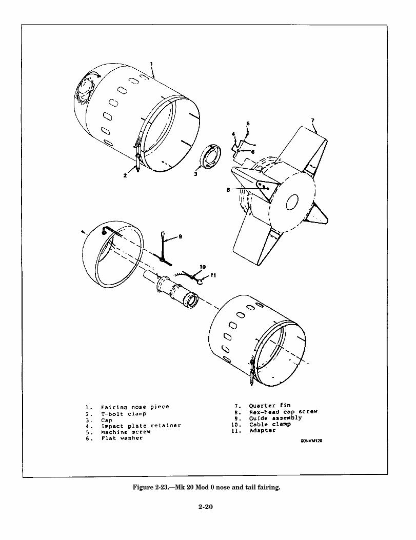
Figure 2-23.—Mk 20 Mod 0 nose and tail fairing.
2-20

Figure 2-24.—Mk 35 Mod 0 parachute pack assembly.
Figure 2-25.—Mk 36 Mod 0 parachute pack assembly.
2-21

OPERATIONAL DESCRIPTION
The Mk 52 and Mk 55 actuation mines employan arming device that contains two hydrostaticallyoperated pistons, the hydrostatic switch piston, andthe extender piston, which delay arming until themine reaches a water depth of approximately 18feet. The hydrostatic switch piston closes switches inthe actuation counter. the clock delay. the sterilizer.and the signal release circuits. The extender pistonserves no purpose in the actuation mines. Both ofthe arming device pistons are held inoperable in thesafe position by safety pins.
After the arming device switches operate, themine is still maintained safe by the clock delayswitches that maintain breaks in the actuation
counter circuits. These switches in the clock delayclose at preset times, from 1 hour to 90 days afteroperation of the arming device switches.
The sterilizer contains a resistor plug and closesa break in the tiring circuit. It does not limit thearmed life of the mine since there are no timingelements installed.
When the mine receives a firing indication, themine batteries provide a voltage for the electricalexplosive fitting, which effects the actuation mine’ssignal. The mine has a delay switch in the floatshield that times the firing of a second electricalfitting, which releases the float from the mine. Seefigure 2-26.
2-22

Figure 2-26.—Mk 52 and Mk 55 actuation mines, sequence of operation.
2-23

RECOMMENDED READING LIST
NOTE: Although the following references were current when this TRAMAN waspublished, their continued currency cannot be assured. Therefore, you need to ensure thatyou arc studying the latest revision.
Mine Components A through C; Description and Class-B Criteria, NAVSEA SW550-AA-MMI-010, Naval SeaSystems Command, Washington, D.C., 1988.
Mine Components D through F; Description and Class-B Criteria, NAVSEA SW550-AA-MMI-020, Naval SeaSystems Command, Washington, D.C., 1988.
Mine Components G through W; Description and Class-B Criteria, NAVSEA SW550-AA-MMI-030, Naval SeaSystems Command, Washington, D.C., 1987.
Mirws, Underwater: Actuation, Description, Assembly, and Tests, NAVSEA SW550-AE-MMI-040, Naval SeaSystems Command, Washington, D.C., 1991.
Mines, Underwater: Exercise and Training; Description and Class-B Criteria, NAVSEA SW550-AE-MMI-010,Naval Sea Systems Command, Washington, D.C., 1989.
2-24

CHAPTER 3
LAYING, HANDLING, SHOP, HUNTING,AND MECHANICAL SWEEP MINES
I
LEARNING OBJECTIVES
Upon completing this chapter, you should be able to do the following:
1. Describe the different types of laying mines.
2. Describe the various components used to assemble laying mines.
3. Describe the different types of handling, shop, hunting, and mechanicalsweep mines.
The mine exercise and training and evaluation For further information on the description andprogram is designed to provide a constant evaluationof the personnel, weapons systems, and associatedequipment. This chapter discusses other exercise andtraining mines used in this program.
LAYING MINES
Laying mines or laying destructors (DST) areexercise and training (ET) configurations that areused by aircraft and submarine crews to practicemine planting techniques. They evaluate the person-nel and the delivery agents in the laying of a minefield. Their cases or explosive sections, as appropri-ate, are inert loaded to service weight. Except for aweighted instrument rack or a search-coil tube thatmaintains center of gravity (CG) characteristics, thecases of laying mines contain no internal com-ponents. Laying mines are painted orange and white,either white with orange stripes or orange withwhite stripes.
As a Mineman, you will need to know thedifferent types of laying mines and their uses. Thissection describes the different types of laying mines.
assembly of laying mines and their components,refer to Mines, Underwater: Laying; Description,Assembly, and Disassembly, NAVSEA SW550-AE-MMI-050; and Mines, Underwater: Exercise andTraining; Description and Class-B Criteria, NAV-SEA SW550-AE-MMI-010.
MK 25 LAYING MINE
The Mk 25 laying mine, shown in figure 3-1, isa recoverable, inert-loaded mine case, with a nom-inal weight of 2,000 pounds. Since a laying minedoes not contain target detecting or actuating mech-anisms, to maintain the CG and the inertial andballistics characteristics identical to its service-mineversion, the Mk 25 laying mine has concrete in thesearch coil tube and in the firing mechanism com-partment,
If the Mk 25 laying mine is to be recovered, aMk 87 sonar transmitter is installed in the instru-ment compartment. For the transmitter to function,a tail cover with four 1/2-inch holes drilled throughit is used. The holes allow sea water to enter theinstrument compartment to activate the transmitter.
3-1

Figure 3-1.—Mk 25 laying mine.
A rubber expanding plug must also be installed inal weight of 1,000 pounds. The Mk 36 simulatesin the hydrostatic switch and extender-well conduit the laying mine characteristics of Mk 52 serviceto confine the flooding of the mine case to only the mines. Like the Mk 25 laying mine, the searchinstrument compartment. coil tube and the instrument compartment are filled
with concrete and the Mk 87 sonar transmitter isMK 36 LAYING MINE located inside the instrument compartment, which is
flooded by the four 1/2-inch holes drilled into theThe Mk 36 laying mine, shown in figure 3-2, is tail cover.
a recoverable, inert-loaded mine case, with a nom-
Figure 3-2.—Mk 36 laying mine.
3-2

Figure 3-3.—Mk 52 and Mk 55 laying mines.
MK 52 AND MK 55 LAYING MINES
The Mk 52 and Mk 55 laying mines, shown infigure 3-3, are inert-loaded shapes identical in sizeand weight to their service mine counterparts. TheMk 52 has a nominal weight of 1,000 pounds, andthe Mk 55 weighs 2,000 pounds. The mines areidentical other than size and flight gear.
There are three versions of the Mk 52 and Mk55 laying mines: one has a locator float tail cover,one has a mammal recovery attachment, and one hasthe standard three-hole tail cover.
The laying mine with the locator float tail coverhas a special tail cover with a locator float well thathouses an ejection spring and an orange-coloredlocator float, all held in the tail cover by the flightgear assembly. Inside the buoyant locator float is acylinder of coiled float line. One end of the floatline is attached to a ring on the tail cover and theother end is secured to the inside bottom of thebuoyant float. As the float rises to the surface, thefloat line is pulled out of the float container.
The laying mine with the mammal recoveryattachment contains two components: an extensivelymodified tail cover and a transmitter holder. Anadditional sonar transmitter is installed. The modi-fied tail cover has an 8-inch diameter ring welded tothe top of the gussets. The sonar transmitter is in-stalled in the transmitter holder at the bottom of thefloat well. The system allows trained sea lions,equipped with grabber mechanisms, to recover lay-ing mines. The standard version of the Mk 52 andMk 55 laying mines that use the standard threehole-tail covers does not employ any recovery/locating features.
The Mk 87 sonar transmitter is optional for theMk 52 and Mk 55 laying mines employing thestandard three-hole tail covers and the locator floattail cover. When used, the transmitter is installed onthe tail cover of the mine. When using the mammalrecovery attachment, the use of the Mk 87 sonartransmitter is mandatory. For this version, the Mk87 sonar transmitter is mounted in the arming devicewell. In addition, when using the mammal recoveryattachment, a 9-kHz sonar transmitter is installed inthe float well of the modified tail cover.
3-3

Figure 3-4.—Mk 56 laying mine.
MK 56 LAYING MINE
The Mk 56 laying mine, shown in figure 3-4, isa recoverable, inert-loaded shape identical in weightand size to the service mine counterpart. The Mk 56laying mine has a nominal weight of 2,000 poundsand consists of a nonfunctional anchor, a mechanismsection, an inert-loaded explosive section, an emptyarming device, and service-mine flight gear. Sincethe anchor is nonfunctional, the mine does notseparate or moor the buoyant mechanism section.
The Mk 56 laying mine does not have a targetdetecting mechanism, so it is ballasted to maintainweight, CG, and inertial and ballistics characteristicsto its service-mine version. This is accomplished bythe use of a concrete-filled instrument rack.
To simulate the same weight distribution as tothe service mine rack, a steel block is installed inthe rack. If the mine is to be recovered, a Mk 87sonar transmitter is installed on the anchor.
MK 57 LAYING MINE
The Mk 57 laying mine, shown in figure 3-5, isa recoverable, inert-loaded shape identical in sizeand weight to the service mine. It is designed solelyfor the training of submarine crews in the techniquesof carrying mines and planting mine fields. It has anominal weight of 2,000 pounds and consists of amodified functioning anchor, a mechanism section,an inert-loaded explosive section, and an emptyarming device.
The Mk 57 laying mine does not have a targetdetecting mechanism; therefore, it is ballasted tomaintain weight and CG characteristics identical toits service-mine version. This is accomplished by aconcrete-filled instrument rack. Like the Mk 56laying mine, it has a steel block installed in therack. The Mk 87 sonar transmitter is installed on theanchor to aid in the recovery of the anchor. Thetransmitter emits signals to locate the anchor so thata diver can attach a recovery cable.
3-4

Figure 3-5.—Mk 57 laying mine.
MK 60 LAYING MINE
The Mk 60 laying mine, shown in figure 3-6, isa recoverable, exercise and training mine identical insize and shape to the service-mine counterpart. TheMk 60 laying mine is designed to train aviation andsubmarine personnel in the techniques of carryingmines and planting mine fields. It has a nominalweight of 2,000 pounds and consists of an inert-loaded mine case and service flight gear.
The Mk 60 exercise and training mine is issuedto the fleet in two operational assemblies (OAs): airlaunched (OA 01) and submarine launched (OA 02).The Mk 87 sonar transmitter is installed on the rearcover of the mine case.
MK 62 AND MK 63 LAYING MINES
The Mk 62 and Mk 63 laying mines, shown infigures 3-7 and 3-8 respectively, are inert-loaded500-pound and 1,000-pound general-purpose bombs.They incorporate an inert-loaded Mk 32 arming
device, a nonoperational Mk 42 firing mechanism,and fully operational fins or tail sections. To facili-tate the recovery operation, the mines are equippedwith Mk 87 sonar transmitters.
MK 65 LAYING MINE
The Mk 65 laying mine, shown in figure 3-9, isa recoverable, inert-loaded shape identical in sizeand shape to its service-mine counterpart. It has anominal weight of 2,000 pounds and consists of amine case, a fairing, a Mk 144 Mod 0 thermal bat-tery, a safety device, and a Mk 7 Mod 1 tail section.
MK 36 AND MK 40 LAYING DESTRUCTORS
The Mk 36 and Mk 40 laying destructors(DSTs), respectively, are 500-pound and 1,000-pound, inert-loaded, general-purpose bombs. Theyincorporate an inert-loaded Mk 32 arming device, anonoperational Mk 42 firing mechanism, and fullyoperational fins or tail sections. To facilitate re-covery operations, they are equipped with the Mk 87sonar transmitter.
3-5

Figure 3-6.—Mk 60 laying mine.
Figure 3-7.—Mk 62 laying mine.
3-6

Figure 3-8.—Mk 63 laying mine.
Figure 3-9.—Mk 65 laying mine.
3-7

LAYING MINE COMPONENTS
A laying mine contains no internal components,except for a weighted instrument rack or a search-coi I tube that maintains CG characteristics. The Mk52 and Mk 55 cases may also employ an optionalmine-locator float, which installs on the tail cover.A laying mine or a DST incorporates functionalflight gear (when applicable) and all componentsthat interface with the planting vehicle. This sectiondescribes these components and how they are usedin laying mines.
SUSPENSION LUGS
Mk 3, Mk 12, Mk 13, Mk 17, and MS3314 Sus-pension lugs may be reused for all flight operationsif, upon inspection, they exhibit no damage to theirthreads or to the suspension arch.
SONAR TRANSMITTERS
The Mk 87 sonar transmitter is the most com-monly used transmitter. Depending on the layingmine, the Mk 87 transmitter may be installed ex-ternally in the arming device well, on the tail cover,or on the side of the bomb case. When the mammalrecovery attachment is used on laying mines, anadditional sonar transmitter (9-kHz Dukane ModelN15A260) is used with the Mk 87.
ARMING DEVICES
The arming devices used on laying mines areidentical to those used on their service-minecounterparts. However, they are inert-loaded.
TAIL COVERS
The tail covers for the Mk 25 and Mk 36 layingmines have four 1/2-inch holes drilled through themto allow water entry to activate the Mk 87 sonartransmitter. The Mk 52 and Mk 55 laying minesuse tail covers that have a circular steel platemeasuring 18 inches in diameter. The plate has asingle well welded to the center of the cover,
measuring 11 13/16 inches deep and 8 13/64 inchesin diameter, which is used to accommodate a float.
MINE LOCATOR FLOAT
The mine locator float, shown in figure 3-10, isused on the Mk 52 and Mk 55 laying mines. Theunit installs in the well of the mine’s tail cover andfunctions as a surface marker for locating andrecovering the mine after planting.
The float itself is a polyethylene container 11inches high and 8 inches in diameter. The containerincludes a 2-inch-diameter plastic tube with 200 feetof nylon twine. The space surrounding the cavity forthe plastic tube is filled with urethane foam. Aplastic cover with a feeder hole for the nylon linesecures the contents of the container in place.
Connected to the nylon line and external to thecontainer is an 18-inch length of wire rope, called aleader. The free end of the leader includes a shackle,which attaches to the mine’s tail cover. The leaderfunctions as a umbilical cord. The plastic tube andthe leader are called the line assembly. They arealso a part of a replacement parts kit that permitsthe locator float to be refurbished for reuse.
Additional components of the float include an8 1/8-inch-diameter polyurethane cushion, an 8 1/8-inch-diameter fiberboard spacer, a coiled spring,three spring clamps, three screws, and three lockwashers. The coiled spring and the spacer installbeneath the float in the well of the mine’s tail cover;clamps, screws, and lock washers hold the spring inplace. The cushion installs over the float and is heldin place by the mine’s flight gear, which alsosecures the float in the tail cover.
The mine locator float operates as follows: Atwater impact and upon release of the flight gear, thecoiled spring ejects the float from the tail cover. Asthe mine sinks to the bottom, the nylon line (securedby the leader to the tail cover) pays out, permittingthe float to surface and to mark the location of thesubmerged mine.
3-8

Figure 3-10.—Mine locator float.
FLOAT ASSEMBLY
The float assembly, shown in figure 3-11, isused in the Mk 65 laying mine. It is cylindrical inshape, 6 1/2 inches in diameter and approximately13 1/2 inches long. The housing is polyethylenefoam, which provides buoyancy. The assembly in-cludes a float line attached to the housing and arapid repair link for attaching the float line to theeyebolt mounted in the float container. This as-sembly is released when the tail section separatesupon water impact. The float assembly is used tolocate the layingment exercises.
FLIGHT GEAR
mine for recovery after deploy-
The flight gear used on laying mines is Code Afully functional. The parachute packs use a Mk 112control unit and a Mk 18 actuator to deploy theparachute after release from the aircraft.
HANDLING, SHOP, HUNTING,AND MECHANICAL SWEEP MINES
To provide proficiency in the loading andplanting of mines, we use laying mines. To provide
proficiency in the handling, assembly, hunting, andsweeping of mines, we use mines specifically designed for those reasons. This section describes thesemines.
For additional information on the description andassembly of these mines, refer to Mines, Under-water: Handling, Shop, Mechanical Sweep, andHunting; Description and Assembly, N A V S E ASW550-AE-MMI-060.
HANDLING MINE
A handling mine is used to train aircraft andsubmarine crews in the techniques of mine handlingand loading on board. Its case is inert loaded toservice weight and contains no internal components,except for a weighted instrument rack used to com-pensate for weight and CG characteristics.
Externally, the case is fitted with flight gear(when applicable) and all components that interfacewith the planting vehicle. A handling mine containsno sonar transmitter or explosives and its flight gearis nonfunctional. The handling mine is paintedbronze.
3-9

Figure 3-11.—Float assembly.
SHOP MINE of mine hunting. Since the purpose of a huntingmine is only to-provide a planted shape, any inert
A shop mine is used for instructional purposes laying mine may be used to serve this purpose.and to develop proficiency in mine assembly andtesting. Its case is inert-loaded and contains all com-ponents necessary to constitute a fully assembled MECHANICAL SWEEP MINEmine. However, dummy or inert loads are sub-stituted for explosive components. The shop mine is A mechanical sweep mine, shown in figure 3-12,painted blue.
HUNTING MINE
A hunting minepersonnel to develop
is an inert-loaded Mk 6 moored mine without actua-tion mechanisms. It is used for developing pro-ficiency in mechanical minesweeping techniques.The case of the mechanical sweep mine is painted
is used by mine locating orange with a white stripe. The anchor is paintedproficiency in the techniques black.
3-10

Figure 3-12.—Mk 6 mechanical sweep mine.
3-11
RECOMMENDED READING LIST
NOTE: Although the following references were current when this TRAMAN waspublished, their continued currency cannot be assured. Therefore, you need to ensure thatyou are studying the latest revision.
Mines, Underwater: Exercise and Training; Class-B Test and Refurbishment, NAVSEA SW550-AE-MMI-020,Naval Sea Systems Command, Washington, D.C., 1989.
Mines, Underwater: Exercise and Training; Description and Class-B Criteria, NAVSEA SW550-AE-MMI-010,Naval Sea Systems Command, Washington, D.C., 1989.
Mines, Underwater: Handling, Shop, Mechanical Sweep, and Hunting; Description and Assembly, NAVSEASW550-AE-MMI-060, Naval Sea Systems Command, Washington, D.C., 1990.
Mines, Underwater: Laying; Description, Assembly, and Disassembly, NAVSEA SW550-AE-MMI-050, NavalSea Systems Command, Washington, D.C., 1990.
3-12

APPENDIX I
GLOSSARY
The entries listed in this appendix are terms as they are used in this training manual.
ALL-UP ASSEMBLY— A term used to designatea completely assembled ET mine.
ASSEMBLY-LEVEL ITEM— A component, con-sisting of one or more parts, which is designedto function as an end item in a mine assembly.
MAINTENANCE— The actions required to retainmaterial in a serviceable condition or to restoreit to a serviceable condition.
SPARES— The assembly-level items maintained onsite in excess of those installed in mine assem-blies.
SUBASSEMBLY— A term used to designate an ETmine storage and shipping configuration.
VISUAL INSPECTION— The class-B testing ofmine components by sight, test, or manipulationwithout the use of test instruments.
MBOM (Mine Bill of Material)— A computer-produced consolidated list for underwater-minematerial.
AI-1


APPENDIX II
ABBREVIATIONS AND ACRONYMS
The entries listed in this appendix are abbreviations and acronyms as they are used in this trainingmanual.
CG— Center of gravity ET— exercise and training
COMINEWARCOM— Commander, Mine Warfare NCEA— non-combat expenditure allocation
CommandOA— operational assembly
COMOMAG— Commander, Mobile Mine Assem-bly Group OCE— officer conducting the exercise
CNO— Chief of Naval Operations RAM— random-access memory
DST— destructor mine VEM— versatile exercise mine
AII-1


APPENDIX III
REFERENCES USED TO DEVELOP THIS TRAMAN
The references listed in this appendix were used to develop this training manual.
Exercise and Training (ET) Mine Material Program, OPNAVINST 8550.9, Chief of’ Naval Operations, Wash-ington. D.C., 1989.
Guidance for Personnel Assigned in Support of Mine Warfare Exercise and Training (ET) operations,COMOMAG/MOMAGINST 3120.2. Mobile Mine Assembly Group, Chadcston, S.C., 1987.
Information Concerning Mine Warfare Exercise and Training (ET) Material Allowancc and Reporting Criteria,COMOMAG/MOMAGINST 8550.9, Mobile Mine Assembly Group, Charleston, S.C., 1994.
Mine Components A through C; Description and Class-B Criteria, NAVSEASystems Command, Washington, D.C., 1988.
Mine Components D through F; Description and Class-B Criteria, NAVSEASystems Command, Washington, D.C., 1988.
Mine Components G through W; Description and Class-B Criteria, NAVSEA
Mines,
Mines,
Mines,
Mines,
Mines,
Mine
Systems Command, Washington, D.C., 1987.
Underwater: Actuation, Description, Assembly, and Tests, NAVSEASystems Command, Washington, D.C., 1991.
Underwater: Exercise and Training; Class-B Test and Refurbishment,Naval Sea Systems Command, Washington, D.C., 1989.
Underwater: Exercise and Training; Description and Class-B Criteria,Naval Sea Systems Command, Washington, D.C., 1989.
SW550-AA-MMI-010, Naval Sea
SW550-AA-MMI-020, Naval Sea
SW550-AA-MMI-030, Naval Sea
SW550-AE-MMI-040, Naval Sea
NAVSEA SW550-AE-MMI-020,
NAVSEA SW550-AE-MMI-010,
Underwater: Handling, Shop, Mechanical Sweep, and Hunting; Description and Assembly, NAVSEASW550-AE-MMI-060, Naval Sea Systems Command, Washington, D.C., 1990.
Underwater: Laying; Description, Assembly, and Disassembly, NAVSEA SW550-AE-MMI-050, NavalSea Systems Command, Washington, D.C., 1990.
Warfare Exercise and Training (ET) Material Maintenance and Refurbishment, C O M O M A G /MOMAGINST 8550.14, Mobile Mine Assembly Group, Charleston, S.C., 1993.
Mine Warfare Exercise and Training (ET) Post Exercise Reporting, COMOMAGIMOMAGINST 8550.1, MobileMine Assembly Group, Charleston, S.C., 1988.
AIII-1

Versatile Exercise Mine Mk 74 Mod 0 (VEM); Description and Maintenance, NAVSEA SW550-AE-MMI-070,Naval Sea Systems Command, Washington, D.C., 1993.
Versatile Excercise Mine Mk 74 Mod 0 (VEM); Organizational Level Procedures Rigging, Deployment, andRecovery, NAVSEA SW570-FO-MMO-050, Naval Sea Systems Command, Washington, D.C., 1990.
AIII-2

INDEX
AActuation mines, 2-1 to 2-24Arming device, 3-8
CConfiguration data, 2-6
DDetection systems, 2-3 to 2-5Drill float shield assembly, 2-9 to 2-10, 2-11
EExercise & training mines
basic allowance, 1-1configurations, 1-3 to 1-4in-water reliability evaluation, 1-2maintenance, 1-3 to 1-4Material Program, 1-1 to 1-3records & reports, 1-2system layout, 1-3
FFlight
actuation mines, 2-1gear, 3-9
Float assembly, 3-9, 3-10
HHandling mine, 3-9Hunting mine, 3-10
IIllustrations
Drill float shield assembly, 2-11Float assembly, 3-10Mine-case tail covers, 2-16Mine locator float, 3-9Mk 10 Mod 0 ET sterilizer, 2-8Mk 17 Mod 0 drill float, 2-10Mk 19 Mod 0 nose & tail fairing, 2-18Mk 19 Mod 1 explosive fitting, 2-14Mk 20 Mod 0 explosive fitting, 2-15Mk 20 Mod 0 nose & tail fairing, 2-20Mk 20 Mod 1 firing mechanism, 2-4Mk 21 Mod 0 clock delay, 2-7
Illustrations (continued)Mk 21 Mod 0 firing mechanism, 2-5Mk 25 laying mine, 3-2Mk 25 Mod 0 signal data recorder, 2-15Mk 27 Mod 0 search coil, 2-8Mk 3 Mod 0 depth compensator, 2-5Mk 35 Mod 0 junction box, 2-9Mk 35 Mod 0 parachute pack assembly, 2-21Mk 36 laying mine, 3-2Mk 36 Mod 0 parachute pack assembly, 2-21Mk 5 Mod 1 ET arming device, 2-7Mk 52 & Mk 55 actuation mines, sequence
of operation, 2-23Mk 52 & Mk 55 laying mines, 3-3Mk 52 actuation mine, 2-2Mk 55 actuation mine, 2-3Mk 56 laying mine, 3-4Mk 57 laying mine, 3-5Mk 6 mechanical sweep mine, 3-11Mk 6 Mod 1 hydrophone, 2-6Mk 60 laying mine, 3-6Mk 62 laying mine, 3-6Mk 63 laying mine, 3-7Mk 64 Mod 3 switch delay, 2-14Mk 65 laying mine, 3-7Mk 87 Mod 0 sonar transmitter, 2-17Mk 115 & Mk 116 smoke & illumination
marine signals, 2-12Mk 125 Mod 0 smoke & illumimation signal,
2-13System layout, ET mine, 1-3
LLaying mines, 3-1 to 3-9
MMechanical sweep mine, 3-10 to 3-11Mine-case tail covers, 2-15 to 2-16Mine locator float, 3-8 to 3-9Mk 3 Mod 0 depth compensator, 2-5Mk 6 Mod 1 hydrophore, 2-5 to 2-6Mk 10 Mod 0 ET sterilizer, 2-8Mk 17 Mod 0 drill float 2-9, 2-10Mk 19 Mod 0 nose & tail fairing, 2-17 to 2-18Mk 19 Mod 1 explosive fitting, 2-14
INDEX-1

Mk 20 Mod 0 nose & tail fairing, 2-19, 2-20Mk 20 Mod 0 explosive fitting, 2-14 to 2-15Mk 21 Mod 0 clock delay, 2-7Mk 25 laying mine, 3-1 to 3-2Mk 25 Mod 0 signal data recorder, 2-15Mk 27 Mod 0 search coil, 2-7 to 2-8Mk 3 instrument rack, 2-9Mk 35 Mod 0 & Mk 36 Mod 9 parachute packs,
2-19, 2-21Mk 35 Mod 0 junction box, 2-8 to 2-9Mk 36 & Mk 40 laying destructors, 3-5Mk 36 laying mine, 3-2Mk 39 Mod 1 control box, 2-8Mk 5 Mod 1 ET arming device, 2-7Mk 52 & Mk 55 laying mines, 3-3Mk 52 & Mk 55 actuation mine components,
2-7 to 2-24Mk 52 Mods 2 & 5 actuation mines, 2-2Mk 55 Mods 2 & 5 actuation mines, 2-3Mk 56 laying mine, 3-4Mk 57 laying mine, 3-4 to 3-5Mk 60 laying mine, 3-5, 3-6Mk 62 & Mk 63 laying mines, 3-5, 3-6 to 3-7Mk 64 Mod 3 switch delay, 2-13 to 2-14
Mk 65 laying mine, 3-5, 3-7Mk 87 Mod 0 sonar transmitter, 2-17Mod 2 detection system, 2-3 to 2-5Mod 5 detection system, 2-5 to 2-6MS3314 & Mk 3 suspension lugs, 2-9
NNonflight actuation mines, 2-2
OOperational assemblies, 2-6Operational description, Mk 52 & Mk 55
actuation mines. 2-22 to 2-23
PPlanting depths, 2-6
SShop mine, 3-10Sonar transmitters, 3-8Suspension lugs, 3-8
TTail covers, 3-8
INDEX-2