milwaukii« wisconsin, u.s.a. - manuals.casecoltingersoll.com · assembly under which it is...
TRANSCRIPT

M I L W A U K I I « W I S C O N S I N , U . S . A .
I

COLT MANUFACTURING CO
342 EAST WARD STREET
MILWAUKEE 7, WISCONSIN Hlimbold-t 1-3420

WARRANTY
We warrant each new Tractor to be free from manufacturing detects in normal service for a period of one (1) commencing with delivery of the tractor to the original user, ejtclu-3ive of engine and hydraulic components as they are warranted by the manufacturer. This warranty also covers attachments purchased. Our obligation under this warranty is limlledtolhe rejlicemenl of repair at a point designated by the company of suc'i parts as shall appear to us lo have been defective. We will not bear the cost of conaequenlial labor or transportation charges in connection with replicement of defective parts unlees authorized by Coll Manufacturing Company. We shall not be liable for damages or contingent liabilities.
INST RUCTIONS FOR ORDERING REPAIR PARTS
This parts book ccmpletely indentifies all parts comprising your COLT TRACTOR In three ways;
1 By part number 3. By part nam* 3- By apperance
The parts list ocntains a breakdown of the tractor into its major assemblies, Bub-asaemblles, and detail parts. To aid in Identifying a part by appearance, each part is indexed to an illustration of the asaemhly ol which it is a part. The flrsl column of the parts list contains reference numbers, which serve as a cross-reference between the listed parts, and the same parts as illuatrated,
INDENTION
The indention of a part in the "Dearnplion" column indicates the relationship of that part to the assembly of which it i a a part. For example: Any pari indented beneath an assembly is available either as a di:tail part, or as a portion ol the assembly under which It is indented, unless specified "NP" (Not priJcurable separately).
QUANTITIES
The quantities listed are determined as follows;
1. The quantity listed for an assembly in the "No. ReqId" column indicates the number of these assembhes used per tractor.
2. The quantity listed in the "No. ReqId" column for a detail part indicates the number of these detail parts used per assembly
INFORMATION NECESSARY FOR PROMPT SERVICE
When ordering parts, always include the following information:
1. The tractor serial number, (This number ifl found on the tractor dash.) 2. The tractor model number, (Model 9 1/Z or Model 7) 3. The exact quantity of detailed parts desired. Identify these parts by
part number, and part description 4. Specify the method of shipment desired. (Air express, freight, etc.)
DIRECT ALL PARTS ORDERS TO YOUR COLT TRACTOR DEALER IN YOUR AREA

I N D E X
FIGURE NO. DESCRIPTION PAGE NO.
1 . HAIN FRAME ASSEMBLY - - - - - - - - - 2
2 . MAIN FRAME COMPONENTS ASSEMBLY- - - - 4
3 . HYDRAULIC DRIVE ASSEMBLY- - - - - - - 6
4 . COLT-A-MATIC DRIVE ASSEMBLY - - - - - 8
5 . ENGINE INSTALLATION ASSEMBLY 10
6 . HYERAULIC MOTOR ASSEMBLY- - - - - - - 1 2
7 . CONTROL VALVE ASSEMBLY- 14
8. HYDRAULIC PUMP ASSEMBLY - - - - - - - 14
9. ELECTRICAL WIRING DIAGRAM ASSEMBLY- - 16

7 "
I C O L T - - .
FIGURE I . MAIN FRA^IE ASSEMBLY
Page J C-101

FHiL'RE 1 . MAIN FRAME \SSEiHI)LV
No . P a r t No . 1 2 .1 -I De s c r i p t i o n ' U
No Number n . \ lN FRA,*1H ASSE,*1BLV - NP 1 3365 0002 . FRAME, Main ( 9 ^ hp) - - - - - - - - - - - - - - - - - - - 1 Is J365 0001 I 2 1395 1)501 . HOOD (Spec i fy s i z e o f eng ine f o r p r o p e r d e c a l ) - - - - - - 1 3 8210 0101 . T R I M , Chrome - R . H . and L . H . - - - - - - - - - - - - - - - 2 I 7177 0500 , ?HROl!D . C o l l - f l - m a t i c d r i v e - - - - - - - - - - - - - - - - i 5 2774 791 . CAPSCREW, Hex heat! 3 / 8 - 1 6 by 1-1/4 i n . - - - - - - - - ^ - 2 6 3064 470 . LOCKWASHER, 3 /8 i n , - - - - - - - - - - - - - - - - - - - 2 7 3005 021 . M I T , Hex 3 / 8 - 1 6 - - - - - - - - - - - - - - - - - - - - - 2 S 3171 010 . FASTENER, Chrome t r i m - - - - - - - - - - - - - - - - - - 6 9 3790 0001 1
10 2775 322 . CAPSCREW, Hex head 1 /2-13 l.y 2 i n . - - - - - - - - - - - - 2 1 1 3064 476 . 1,0CKWASH!!R, 1/2 i n , - - - - - - - - - - - - - - - - - - - 2 12 3005 031 . Nl!T, H e i 1 /2-13 - 2 13 222S 0501 . LEVER, Implemei i l Ipnsh b u l l o n l - - - - - - - - - - - - - - 1 14 5351 0101 1 15 3385 187 . P I N , R o l l - - - - - - - - - - - - - - - - - - - - - - - - 1 16 5290 0102 . PAIS, F o o l - R . H . - - - - - - - - - - 1 17 5290 0101 . PAD, F o o i - L . H . - - - - - - - - - - - - - - - - - - - - - 1 IR 2774 771 2 19 3064 •170 , LOChWASHER, 3 /8 i n . - 2 20 3005 021 2 21 4598 950 . QR I P , Rubber - imp1emeu t l e v e r - - - - - - - - - - - - - - 1 22 2320 3401 I 23 3101 572 4 2i 6555 364 2 1 25 5135 152 4 26 2225 0001 1 27 6555 3321 1 2B 1 127 0337 1 29 3393 240 1
Not 1 1 l u s t r a t e d
C O ILT.
C - l O l Page 2

— . - C O L T - -%- 4̂7 „ 23 Q
FIGURE 2 . MAIN E~RAME COMPONENTS INSTALLATION
Pmta 3 C - 1 0 2

F I G U R E 2 . M A I N F R A M E COMPONENTS I N S T A U L A T I D N
R e f . No. P a r t No , 1 2 3 4 D e s c r i p t i o n
No, H e q ' d
, No Number WAIN FRAME COMPONENTS INSTALLATION- - - - - - - - NP 1 4475 0001 1 2 2775 281 . CAPSCREW, Hex head 1/2-13 by 1 i n . - - - - - - - 10 3 3064 476 , LOCKWASHER, 1/2 i n . - 16 4 2755 0500 1 5 3551 7001 1 t 2774 521 . CAPSCREW, Hex head 5 / 1 6 - 1 8 by 3 /4 i n . - - - - -7 3064 467 . LOCKWASHER, 5 / 1 6 i n . - - - - - - - - - - - - - -
ft 4685 0804 , JOINT, B a l l 1/2 i n . - 4 6596 0601 . ROD, Reach ( s t e e r i n e ) - - - - - - - - - - - - - I
10 6595 0100 1 a 3005 031 . NUT, Hex 1 /2-13 - - - - - - - - - - - - - - - -12 5358 0101 . P I N , K i n g - R . H . - - - - - - - - - - - - - - - - 1 13* 5358 0401 . P I N , K i n g - L . H . 1 14 3805 252 . F I T T I N G , H y d r a u l i c 1/8 i n , - - - - - 4 15 1195 0001 1 16 3060 488 , WASHER, 3/4 i n . - - - - - - - - - - - - - - - - 4 17 3070 317 I S 5355 0601 1 19 8601 200J , WASHER, A x l e p i n 1 20 307O 621 . P I N , C o t t e r 3 /16 by 1-1/4 i n , - - - - - - - - - 1 21 3745 0101 , COLLMN ASSEM, S t e e r i n g - - - 1 22 3060 025 , WASHER, F l a t 1/4 i n . - - - - - - - - - 2 23 3005 013 , NUT, Hex 1/4-20 - . - 4 24 277 4 781 . CAPSCREW, Hex head 3 / 8 - 1 6 by 1 i n , -25 3064 470 . LOCKWASHER, 3 /8 i n . - - - - - - - - - - - - - - 4 26 1549 0001 . BATTERY - - - - - 1 27 3050 569 1 28 8652 0501 1 29 7616 0101 1 30 7905 1305 1 31 2349 5001 1 32 7615 0501 . STRAP, G a s o l i n e t a n k m o u n t i n g - - - - - - - - - 2 33 2837 613 4 3-1 3048 040 . NUT, Hex #10-24 - - - - 4 3S 2076 205 . F I T T I N G , F u e l l i n e - - - - - - - - -36 4425 2004 . HOSE, Rubber ( f u e l l i n e ) - - - - - - - 1 37 3215 0101 1 3a 5075 142T I 39 2462 0110 1 40 6591 0355 2 41 3060 464 42 2774 7 7 ] 4 3 2060 0001 1 44 7^85 0500 . SPRING, T r a c t o r s e a t - - - - - - - - - - - - - - 1 45 6804 3120 1 4 6̂ : 2830 152S 1 47 2601 R20 . BOLT, C a r r i a g e 7 / 1 6 - 1 4 by 1 i n , - - - 1 48 3060 034 , WASHER, 7 /16 i n , - - - I 49 3008 347 . NUT, Square 7 / 1 6 - 1 4 - - - - - - - - - ] 50 3070 623 SI 3208 0501 1 52« 3208 0502 . FENDER, Rear w h e e l R . H . - - - - - - - - - - - - 1 53 2774 531 4 54 3005 016 . NUT, Hex 5 / 1 6 - 1 8 - _ 4 55 9050 0101 . WHEEL ASSi;.^. F r o n t - - - - - - - - - -56« 8005 0447 I 57« 6183 0955 ] 58« 8275 0356 1 59 2167 1235 . BRACKET, Rear h i t c h - - - 1
« Not I 1 l u s t r a t e d
CO L J -
c -102 Page 4


FlOliRE i . HVr«AULIC DRIVE ASSEMBLY
R e f . No, P a r i No, 1 2 3 4 D e s c r i p t ! o n
No. Req '
_ No Nmiiber NP 1 2130 6007 . BRACKET, Piunp m o u n t i n g ( 9 ^ h p ) - - - - - - - - - - - 1 15 2130 6005 . BRACKET, Pump m o u n t i n g ( 7 h p i - - - - - - - - - - - 1 2 2775 016 , CAPSCREW, He^ head 7 / 1 6 - 1 4 bj 1 2 i n . ( 9^ h p ) - - - 4 2'-- 2774 761 . CAPSCRLW , Hex head 3 / 8 - 1 6 h j L i i n . (7 h p ) - - - - 4 .1 3064 473 . LOCKWASHER, 7 '16 i n , ( 9 ^ h p ) - - - - - - - - - - - - 4 3« 3U64 170 , LOCKWASHER, 3/8 i n . (7 h p ) _ _ _ _ _ _ A •1 2703 35 01 . COLIPLISO, D r i v t ; - - - - - - - - - - - 1 5 3350 119 . KEY, Squnre 1/4 by 1/4 b> 2 i n . - - - - - 1 6 3366 204 , KEY, W n o , l r u i £ - - - - - - - - - - - - - - 1 7 5 94 3 0400 . PUMP, H \ d r a u l i c ( h p ) ( s e i f i g u r e 8 ) - - - - - - 1 7k 5943 0350 , PUMP, H y d r a u l i c (7 hp) (see f i g u r e « ) - - - - - - - 1 8 2774 801 2 9 3005 021 . NUT, Hex 3 / 8 - 1 6 - 2
10 1962 080 . CONNKCTOD, Male 1-1/16 by 3/4 SAL ( 9 ^ hp) - - - - - I 10-> 1962 065 1 11 1962 150 , CONNECTOR, ^lale 3/4 by 1/2 ^ A L - 1 W 8258 1500 1 U 8^58 1550 , TUBE ASMl"^, Pump p r e s s u r e - - - - - - - - - - - - - 1 11 8258 162 5 1 15 825 8 1660 . TUBE ASSJi*l, Moto r l o r w a r i l - lOp - - - - - - - - - - 1 16 8258 1740 1 17 1962 055 2 18 1500 014 , NIPPLE, 3/4 by 1-1/4 i n , - - - - - - - - - - - - - - 1 19 1504 336 . REDUCER, 1 by 3 /4 i n . - - - - - - - - - - - - - - - 2 20 1575 035 . TEE, 1 i l l . - 1 21 6690 05 00 , SCREEN, E i l l c r - - - - - - - - - - - - - - - - - - - 1 22 1558 645 . PLUG, P ipe I i n . - 1 23 1980 260 1 24 19H0 245 . ELBOW, m" - 1/2 i n , - - - - - - 2 25 1504 331 , REDUCER, 3/4 by I / 2 i n - - - - - - - - - - - - - - - 1 26 1962 030 . CONNECTOi;, Male 1/2 b> 1/2 i n . - . - 3 27 2774 573 3 28 3064 467 . LOCKWASHER, 5 /16 i n . - - - - - - - - - - - - - - - - 4 29 3005 018 . NUT, Hex 5 / 1 6 - 1 8 - _ - 4 30 8340 1525 1 31 3070 003 , P I N , C o t t e r 1/16 by 1/2 i n - 1 32 3302 066 1 33 4970 4700 , LEVER, V a l v e - - - - - - - - 1 34 2924 052 2 35 6594 5530 1 36 2774 521 2 37 4790 054 0 1 38 4725 1045 1 39 4S60 1500 1 40 3585 7862 1 41 5 024 0001 1 42 2T74 781 4 43 3064 470 6 44 3393 490 1 45 2774 528 1
« Not 11 i u s t r a t e d
C O L T -
C-103 Page 6

- C O L T - -
FIGLRE A. COLT-A-MATIC DRIVE ASSEMBLY
Page 7 C-104
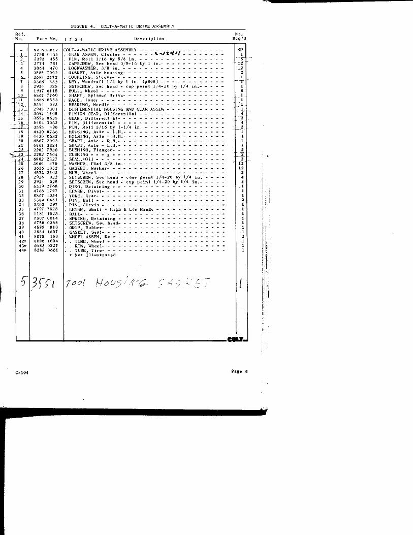
FiaLBE 4 , COLT-A-M.\TIC DRIVE ASSEMIiLY
ReE. No. Psr-t No, L 2 3 4 Descr i p t i o n
No, Req M
1 2__ 3 4 5
, - 6 -7 8
JO 11 12
_14. -15 -Lt__ - i l ls 19 20 21
-23..-
2b 26 27 28 29 30 31 32 33 34 35 36 37 38 39 40 41 42* 43* 44«
N 0 N iiml] e r 3750 0135 3393 455 2774 781 3064 470 3585 7002 2688 2172 3366 5 52 2924 025 1917 611S 6867 7760 1688 0553 5394 093 2945 7301
3692 1105 3693 0635 5404 3062 3393 4 90 4430 0766 4430 0632 6867 2002 6867 3824 2202 7930 2202 7504 6802 2327 3060 470 3636 1052 4573 2102 2924 032 2924 025 6339 2768 4768 1797 8867 1054 5384 0651 3302 297 4797 7525 1181 1523. 7507 0014 6758 03SS 4598 810 3554 1607 8075 150 8006 1004 6183 0227 8283 0661
COLT-A-MATIC DRIVE ASSE.MBLV - - - - - - - - - - - -. GEAR ASSEM, C l u s t e r - - - - - - %.~J\*tff - - . . . P I N , R o l l 3 /16 bv 5/8 i n . - . -, CAPSCREW, Hex bend 3 / 8 - 1 6 bv 1 i n . -, LOCKWASHER, 3/K i n . -. GASKET, A x l e h o u s i n g - - - - - - -. COUPLING, S l e e v e . KEY, Woodru f f 1/4 by 1 i n . {#808} - - - - - - - -. SETSCREW, Soc head - cup p o i n t 1 ' 4 -20 by 1/4 i n , -, BOLT, Wheel . SHAFT, S p l i n e d d r i v e - - - - - - - - - - - - - - -. RACE, I n n e r - - - - - - - - - - - - - - - - - - -. BEARING, Needle - - - -. DIFFERENTIAL HOISING AND GEAR ASSEM - - - - - - -. PINION GEAR, D i K e r e n t i a l - - - - - - - - - - - -. GEAR, D i f l e r e n l i a l - - - - - - - - - - - - - - - -, P I N , D i f f e r e n t i a l - - - - - - - - - - - - - - - -. P I N , R o l l 3 / 1 6 by 1-1/4 i n . - - - - - - - - - - -. HOUSING, A x l e - L . H . - - - - - - - - - - - - - - -. HOUSING, A x l e - R . H . , SflAFT, A x l e - R . H . - - - - - - - - - - - - - - - -. SHAFT, A x l e - L . H . - - -. BUSHING, F l a n g e d - - - - - - - - - - - - - - - - -. BL'SHING - - - K - - - - - - - - - - - - - - - - -, S E A L , ' O i l -, WASHER, F l a t 3/S i n . - - - - - - - - - - - - - - -. GASKET, Washer- - - - - - - - - - - - - - - - - -. HUB, Wheel-. SETSCREW, Soc head - cone p o i n t 1 /4-20 by 1/4 i n , . SETSCREW, Soc head - cup p o i n t 1 /4-20 by 1/4 i n , -. R ING, R e t a i n i n g . LEVER, P i v o t -. YOKE, Gear- - - - - -. P I N , R o l l - -, P I N , C l e v i s - - - - - - - - - - - - - -. LEVER, S h a f t - H i g h & Low Range . BALL- - - - - - - - -. SPRING. R e t a i n i n g . SETSCREW, Soc head- - - - - - -, GRIP, Rubber - - - - - - - - - - - - - - - - - - -. GASKET, S e a l - - - - - - - - - - - -. WHEEL ASSEM, Rear - - - - - - - - - - - - - - - -. . T I R E , Wheel - - - - - - - - - - . - . . . R I M , Wheel - - - -, . TUBE, T i r e _ _ _ _ _ _
Not I l l u s t r a t e d
NP 1
12 2
2
2 12 12
2
C.104 Page 8

Page 9 C-105

FIGLIRt; 5 . ENGINE INSTALLATiON ASSEMBLY
INDEX NUMBER
PART NUMBER DESCRII'TION
UNITS PER
ASSEM
1 Is 2 2'.: 3 3v--1 5 6 7 8 9
to 11 12 13 14 15 16 17 18
No Number 3170 0002 3170 0001 L751 0503 1751 0501 5025 0002 5025 0001 5017 2006 2774 531 3060 028 3064 467 3005 016 2098 7805 2072 0651 2942 0169 2775 322 3064 3005 1535
476 031 577
8261 9175 5048 2635 1550 035
ENGINE INSTALLATION ASSEMBLY- - - - -ENGINE ASSEM. ( 9 ^ ho) ENGINE ASSE,M. (7 h p ) - - - - - - - -" V " BELT (9J! h p ) -" V " BELT (7 hp) - - - - - - - - - -GENERATOR, M o t o r ( 9 i h p ) -GENERATOR, M o t o r (7 h p ) SHEAVE, G e n e r a t o r - - - - - - - - -CAPSCREW, Hex head 5 / 1 6 - 1 8 by 1 i n . WASHER, F l a t 5 / 1 6 i n , - - - - - - -LOCKWASHER, 5 / 1 6 i n , - - - - - - - -NUT, Hex 5 / I 6 - I 8 - - - - - - - - - -BRACKET, G e n e r a t o r a d j u s t m e n t - - -BRACkET. Choke c a b l e - - - - - - - -DEFLECTOR, Hea l (7 h p ) - - - - - - -CAPSCREW, Hex head 1 /2-13 by 2 i n , -LOCKWASHER, 1/2 i n -NUT. Hex 1 /2-13 - -ELBOW, 90^-TUBING, Exhaus t f l e x i b l e - - - - - -MUFELER, E x h a u s t - - - - - - - - - -NIPPLE, C lose - - - - - - - - - - -* Not I 1 l u s t r a t e d
NP 1 1 1 1 1 1 1 2 1 2 2 1 1 I 4 4 4 1 1 1 1
C-105
COLT.
Page 10


FIGURE 6 . HYDRAULIC MOTOR ASSB1BLY
Re I . No, P a r i No,
_ S024 0001 1 5215 0633 Z 3366 370 3 5688 0835 4 3766 0122 5 6866 4616 6 7415 0315 7 6800 0250 8 6727 2081 9 6025 0001
10 J715 0530 11 6726 1965 \Z 5215 0427 13 6803 2462 14 S540 3501 IS 5795 4380 16 2744 0176 17 5215 0762 18 3384 710 19 4537 5340 20 9617 0502
[ 2 3 4 De 3cr i p t i on
HYWiAULIC MOTOR ASSEMBLY- - - - - - - - - - - - - -, SEAL, " 0 " R i n g - - - - - - - - - - - - - - - - - -. KEY, W o o d r u i l - - - - - - - - - -, PLATE, Spacer - - - - - - - - - - - - - - - - - -, GEROTOR SET - -. DRIVE, T l i i c k end- - - - - - - - - - - - - - - - -. SPACER- - - - - - - - - - - - - - - - - - - - - -, SEAL, O i l - - - - - -. CAPSCREW, S p e c i a l 5 / 1 6 - 1 8 by 5 /8 i n . -, RACE, B e a r i n g - - - - - - - - - - - - - - - - - -, BEARING, T h r u s t - - - - - - - - - - - - - - - - -. CAPSCREW, S p e c i a l 1/4-20 by 1-3/4 i n . - - - - - -. SEAL, "O" R i n g - - - - - - - - - - - - - - - - - -. SEAL, Quad- - - - - - - - - - - - - - - - - - - -. PLATE, M o u n t i n g , PLUG, H o u s i n g . CAP, End- - - - - - - - - - - - - - - - - - - - -, SEAL, "O" R i n g - - - - - - - - - -, P I N , R o l l e d 1/4 by 1 i n . - - - - - - - - - - - - -. HOUSING AND SPOOL ASSEM, M o t o r - - - - - - - - - -REPAIR K I T , M o t o r { c o n s i s t s of i t e m s 1 , 7 , 12 & 13)
No . R e q ' d
C O L T J
C-106 Page 12

FIGURE 7 , CONTROL VALVE ASSEMBLY
. C O L T - _
F i a m E 8 . HVORAELTC PLi^P ASSEMBLY
Page 13 C-107

FIGURE 7 . CONTROL VALVE ASSLMULY
R e f . M"-No. P a r t No. 1 2 3 -t D e s c r i p t i o n R e q ' d
_ 8340 1525 CONTROL VALVt ASSEMBLY - - - - - - - - - - - - - - - - - - 1 1 H356 4207 , BODY, C o n t r o l v a l v e - - - - - - - - - - - - - - - - - - - 1 z 83B4 0002 1 3 «430 1120 . " 0 " RING- - - 1 4 8430 0972 . " 0 " RING- - - - - - - - - - - - - - - - - - - - - - - - - 1 5 8469 1230 1 6 8505 3204 1 7 8558 3851 . WASHER, S p r i n g - - - - - - - - - - - - - - . . - 1 K K402 7001 1 9 8487 5445 1
ID 8427 6105 1 11 8426 7715 1 12 8558 6723 . WASHER, S-top 1 13 S3N3 2145 1 14 8397 0004 ] 15 S505 1213 . SPRING, B a l l - - - - - - - 1 16 835 2 0703 1 17 8424 4332 . LOCKWASHER- - - - - - 1 IK H377 5220 1 19 8424 3701 . LOCKWASHER 2 20 8377 4117 . CAPSCREW, Hexagon head- - - _ - _ -
- C O
2
FIGURE 8. HYDRAULIC PUMP ASSE-MBLV
R e f . No. P a r t No, 1 2 3 4 D e s c r i p t i o n
HVIDRAULIC PUMP ASSFIMBLY ( 9 i h p ) - - -HYDRAULIC PUMP ASSEMBLY (7 h p ) - - - -
COVER, Rear ( 9 ^ h p } - - - - - - - -COVER, Rear (7 h p ) - - - - - - - - -CAPSCREW, Hexagon head ( 9 i h p ) - - -CAPSCREW, Hexagon head (7 hp) - - -GASKET, Seal (9-j hp) - - - - - - - -GASKET, Sea l {7 hp) - - - - - - - -130DY ( 9 i h p ) - - -BODY (7 hp) - - - - - - - - - - - -BEARING ( 9 i b p ) - - - - - - - - - -BEARING (7 h p ) - - - -GEAR, D r i v e n ( 9 ^ h p ) - - - - - - - -GEAR, D r i v e n (7 hp) - - - - - - - -GEAR, D r i v e ( 9 ^ h p ) - - - - - - - -GEAR, D r i v e (7 h p ) - - - - - - - - -KEY, Woodru f f - - - - - - - - - - -SEAL, Gasket ( 9 ^ h p ) - - - - - - - -SEAL, Gasket {7 hp) - - - - - - - -SPACER (9^ hp) SPACER (7 h p ) - - - - - - - - - - -COVER, F r o n t (S^ h p ) - - - - - - - -COVER, F r o n t (7 hp) - - - - - - - -SEAL, S h a f t - - - - - - - - - - - -
Not I l l u s t r a t e d
N o , Req M
5943 0400 5943 0350
1 5970 1101 1- 5970 1097 2 5970 6405 2« 5 970 6403 3 5970 2315 3i ' 5970 2312 4 5970 0514 4s 5970 0511 5 5970 0351
5970 0347 6 5970 2640 6̂ ; 5970 2635 7 5970 2530 7tt 5970 2525 8 3366 204 9 5970 6308 9;i 5970 6304
10 5970 7501 10'̂ 5970 7497 1 1 5970 1201 1 1 - 5970 1196 12 5970 6702
- C O L T J
C-107 Page 14

ST. BAT. IGN.
\ V V V
COIL + TERMINAL
TO ITEM 12 "L" TERMINAL
TO ITEM 6 CENTER POST
El V a o A
CENTER POST
TO ITEM 12 "F" TERMINAL
- C O L T . -
n
V BAT. / 1
y \ - 15
II
GENERATOR BRACKET GROUND
FIGURE 9. ELECTRICAL WIRING DIAGRAM ASSEMBLY
Page 15 C-108

FIOURE 9. ELECTRICAL WIRING DIAGRAM ASSEMBLY
R e f . No.
I 2 3 4 5 6 7 8 9
10 11 12 13 13« 14 15 16
P a r t No. 1 2 3 4 De scr j p t i o n
No Number 7889 8407 8712 0355 8712 0628 8712 0524 8712 0616 7893 0065 8712 0312 1549 0001 2229 3307 2229 3296 2229 3301 6113 0124 3758 0129 3758 0127 2774 269 3005 013 3064 464
ELECTRICAL WIRING DIAGRAM ASSEMBLY- - -SWITCH, Key s t a r t - - - - - - - - - -WIRE, Red 53 i n . - - - - - - - - - - -WIRE, Y e l l o w 48 i n -WIRE, Green 35 i n , - - - - - - - - - -WIRE, B l a c k 45 i n . -SOLENOID, S t a r t i n g - - - - - - - - - -WIRE, W h i t e 1 0 - 1 / 2 i n . - - - - - - - -BATTERY -CABLE, G e n e r a t o r 31 i n . - - - - - - • CABLE, B a t t e r y 16 i n . . . CABLE, B a t t e r y 22 i n •
. REGULATOR, V o l t a g e - - - - - - - - - -
. GENERATOR ( 9 ^ h p ) - - - - - - - - - -GENERATOR (7 h p ) - _ _ _ . CAPSCREW, Hex head 1 /4-20 by 5 /8 i n . -NUT, Hex 1/4-20 LOCKWASHER, 1/4 i n • « Not I l l u s t r a t e d
No. R e q ' d
NP

1 V
I