milling machine-types-operations..etc..from l.narayanan,m.e.,ap.mech
TRANSCRIPT

MAHA BARATHIO ENGINEERING COLLEGE,
CHINASALEM TK.,VILLUPURAM DT.,
Pre pared by:-
l.NARAYANAN,M.E.,ASST. PROFESSOR
Dept. of mechanical Engg

unit-3Milling machines
l.NARAYANAN,M.E.,ASST. PROFESSOR
Dept. of mechanical Engg.

CONTENTS
Milling
Milling Machines
Milling Operations
Specifications of Milling Machine
Grinding
Abrasives & Bonding Materials
Grinding Machines

MILLING
Milling: is a metal cutting operation inwhich the excess material from the workpiece is removed by rotating multipointcutting tool called milling cutter.
Milling machine: is a power operatedmachine tool in which work piece mountedon a moving table is machined to variousshapes when moved under a slow revolvingserrated cutter.

CLASSIFICATION OF MILLING
MACHINES
1. Column and knee milling machines
a. Plain column & knee type milling machine
- Horizontal spindle type
- Vertical spindle type
2. Bed type milling machine
3. Planer type milling machine
4. Special purpose milling machine
a. Tracer controlled milling machine
b. Thread milling machine
c. CNC milling machine
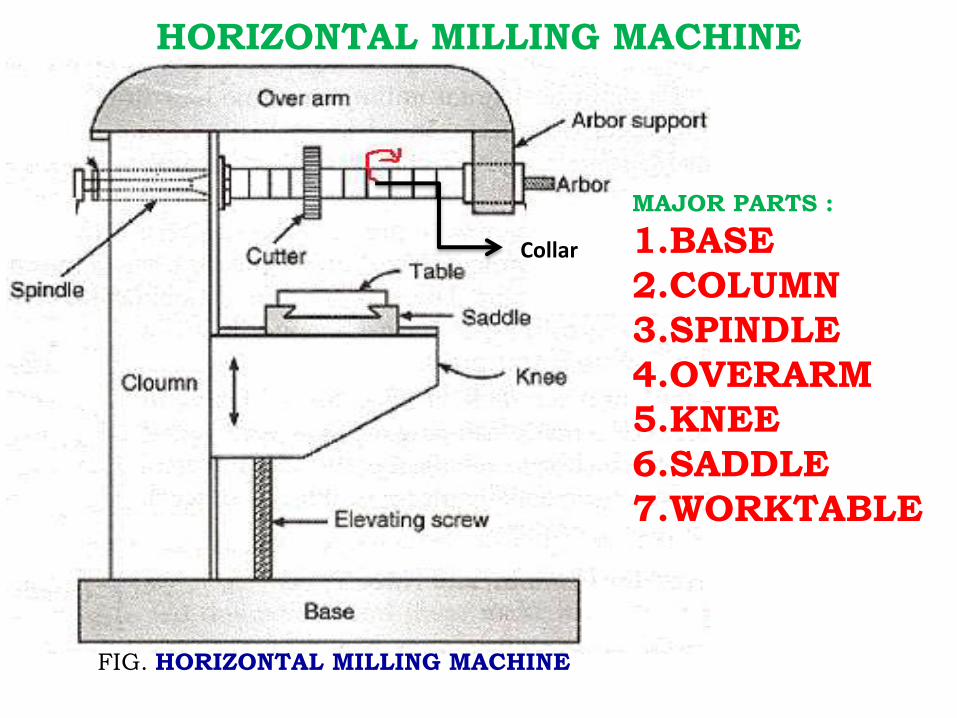
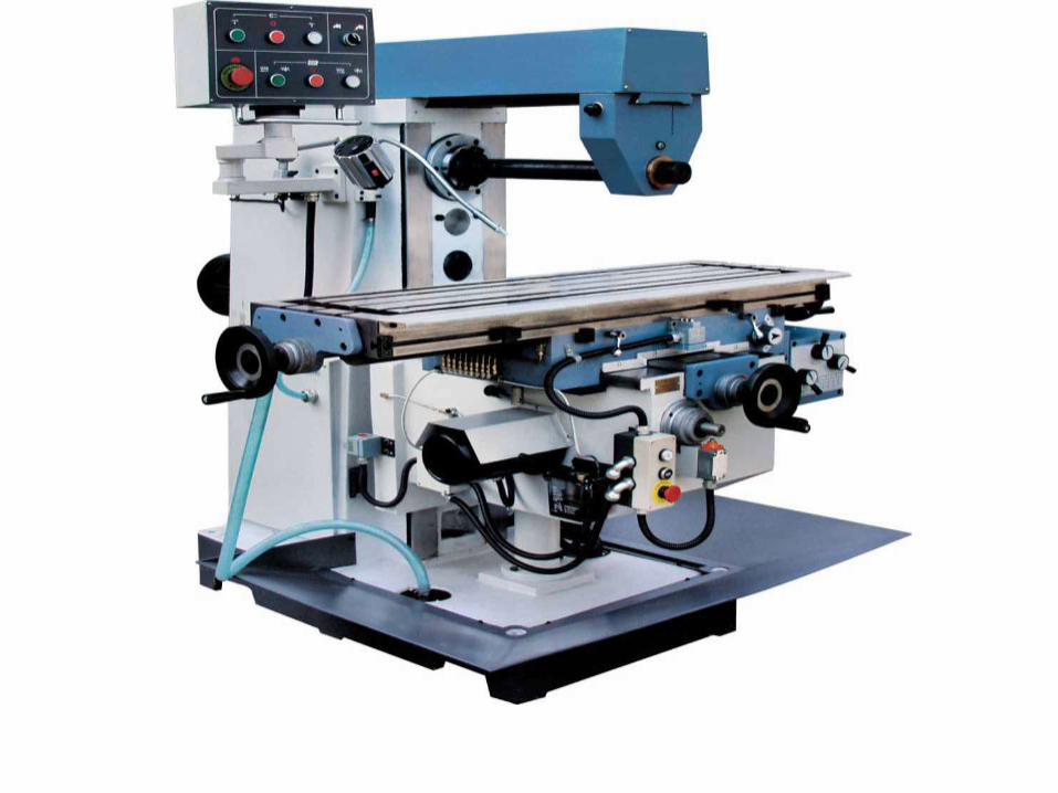
HORIZONTAL MILLING MACHINE
FIG. HORIZONTAL MILLING MACHINE
MAJOR PARTS :
1.BASE
2.COLUMN
3.SPINDLE
4.OVERARM
5.KNEE
6.SADDLE
7.WORKTABLE
Collar


VERTICAL MILLING
MACHINE
MAJOR PARTS :
1.BASE
2.COLUMN
3.SPINDLE
4.SPINDLE
HEAD
5.KNEE
6.SADDLE
7.WORKTABLE


DIFFERENCES BETWEEN HORIZONTAL &
VERTICAL MILLING MACHINES
SL. NO. HORIZONTAL MILLING MACHINE VERTICAL MILLING MACHINE
01Spindle is horizontal &
parallel to the worktable.
Spindle is vertical &
perpendicular to the worktable.
02Cutter cannot be moved up
& down.
Cutter can be moved up &
down.
03Cutter is mounted on the
arbor.
Cutter is directly mounted on
the spindle.
04 Spindle cannot be tilted.Spindle can be tilted for
angular cutting.
05
Operations such as plain
milling, gear cutting, form
milling, straddle milling,
gang milling etc., can be
performed.
Operations such as slot
milling, T-slot milling, angular
milling, flat milling etc., can be
performed and also drilling,
boring and reaming can be
carried out.

PRINCIPLE OF MILLING

COMPARISON BETWEEN UP MILLING & DOWN MILLING
SL.
NO.
UP MILLING
(CONVENTIONAL MILLING)
DOWN MILLING
(CLIMB MILLING)
01 Work piece fed in the
opposite direction that of the
cutter.
Work piece fed in the same
direction that of the cutter.
02 Chips are progressively
thicker.
Chips are progressively thinner.
03 Strong clamping is required
since the cutting force is
directed upwards & tends to
lift the work piece.
Strong clamping is not required
since the cutting force is directed
downwards & keep the work piece
pressed to the table.
04 Gives poor surface finish,
since chips gets accumulated
at the cutting zone.
Gives good surface finish, since
the chips are thrown away during
cutting.
05 Used for hard materials. Used for soft materials and
finishing operations.

MILLING OPERATIONS
Plain or slab milling
Face milling
End milling
Side milling
Slot milling
Angular milling
Form milling
Straddle milling
Gang milling
Slitting or saw milling
Gear cutting

PLAIN/SURFACE/ SLAB MILLING
FIG. PLAIN MILLING
Plain Milling:
Process to get the flat
surface on the work
piece in which the
cutter axis and work
piece axis are parallel.
Cutter: Plain/ Slab
milling cutter.
Machine: Horizontal
Milling m/c.

PLAIN/SURFACE/ SLAB MILLING
FIG. PLAIN MILLING
Work piece
Plain mill cutter

FACE MILLING
FIG. FACE MILLING
Face Milling:
Operation carried out
for producing a flat
surface, which is
perpendicular to the
axis of rotating
cutter.
Cutter: Face milling cutter.
Machine: Vertical Milling
Machine

END MILLING
FIG. END MILLING
End Milling:
Operation performed
for producing flat
surfaces, slots,
grooves or finishing
the edges of the work
piece.
Cutter: End milling
cutter.
Machine: Vertical
Milling Machine

SIDE MILLING
FIG. END MILLING
SIDE MILLING : Operation
performed for
producing flat
surfaces, slots,
grooves or finishing
the edges of the work
piece.
Cutter: End milling
cutter.
Machine: Horizontal
Milling Machine

SLOT MILLING
FIG. T-SLOT MILLING
SLOT Milling:
Operation of
producing slots like T-
slots, plain slots,
dovetail slots etc.,
Cutter: End milling
cutter, T-slot cutter,
dovetail cutter or side
milling cutter
Machine: Vertical
Milling Machine


ANGULAR MILLING
FIG. ANGULAR MILLING
Angular Milling:
Operation of
producing all types of
angular cuts like V-
notches and grooves,
serrations and angular
surfaces.
Cutter: Double angle
cutter.
Machine: Horizontal
Milling Machine

FORM MILLINGEnd Milling:
Operation of producing
all types of angular cuts
like V-notches and
grooves, serrations and
angular surfaces.
Cutter: Double angle
cutter.
Machine: Horizontal
Milling Machine


FIG. FORM MILLING

STRADDLE MILLING
FIG. STRADDLE MILLING
Straddle Milling:
Operation of machining
two parallel surfaces
simultaneously on a work
piece.
Cutter: 2 or more side &
face milling cutters
Machine: Horizontal
Milling Machine

STRADDLE MILLING

GANG MILLING
FIG. GANG MILLING
Gang Milling:
Process to get
different profiles on
the work piece
simultaneously with
two or more cutters
at one stretch.
Cutter: Different
cutters as required.
Machine: Horizontal
Milling Machine

GANG MILLING


CLASSIFICATION OF MILLING CUTTERS1.Plain milling cutter2.Face milling cutter3. End milling cutter4.Angle milling cutter5.T-slot milling cutter6.Slitting milling cutter7.Form milling cutter8.Fly cutter9.Woodruff key slot milling cutter
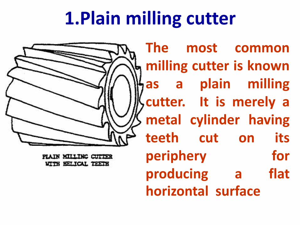
1.Plain milling cutter
The most commonmilling cutter is knownas a plain millingcutter. It is merely ametal cylinder havingteeth cut on itsperiphery forproducing a flathorizontal surface

1(a).SLAB MILLING CUTTER• Cutter width extends beyond the work piece
on both sides
• Process where axis of cutting tool is
parallel to the work piece surface to be
machined
• Used to create flat surfaces or slots
• Cutter may have either straight or helical teeth

1(a).SLAB MILLING CUTTER

1.Plain milling cutter

2.SIDE MILLING CUTTER
Side milling cutters have teeth on its
periphery and also on one or both of
its sides. They are intended for
removing metal from the sides of the
work piece. There are different types
of side milling cutters namely face
and side milling cutter, half side
milling cutter.

2.SIDE MILLING CUTTER

3.END MILLING CUTTERS
These cutters have cutting
teeth on the end as well as on
the periphery of the cutter. It
is made of two parts – body
and shank. The shanks of the
cutter may be straight or
taper.

3.END MILLING CUTTERS

4.Metal slitting saw• It is intended for cutting narrow,
deep slots and for parting off
operation. The teeth are cut on the
circumference of the cutter. The
width of the cutter is limited. The
outside diameter of the cutter will
be up to 200mm and width of the
cutter ranges from 0.75mm to
7mm.

4.Metal slitting saw
5.Angle milling cutterThe teeth of the angle milling
cutter are not parallel to the axis but
are at an angle to it. By using angle
milling cutter, inclined surfaces,
bevels and helical grooves are
machined. There are two types of
angle milling cutter
1. Single angle milling cutter and
2.double angle milling cutter.

5.Angle milling cutter

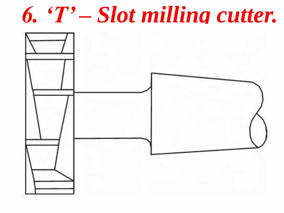
6. ‘T’ – Slot milling cutter.It is a special form of end
mills intended for machining‘T’- slots. It looks like a sidemilling cutter with a shank. Thecutters have cutting teeth onthe periphery as well as onboth sides of the cutter.
6. ‘T’ – Slot milling cutter.

7. Fly cutterFly cutter is the simplest form of cutter. Itconsists of a single point cutting toolattached to the end of the arbor. Thecutting edge may be formed to reproducea contoured surface. They are used whenstandard cutters are not available. Thework is done very slowly because of asingle cutting edge.

Fly cutter

8.Formed cutter
Formed cutters have irregularprofiles on their cutting edges toproduce required outlines on thework. Concave and convex millingcutters are used to produceconvex and concave surfacesrespectively.

SPECIFICATIONS OF MILLING MACHINE
1. Size of the work table: expressed in length x width Eg: 1500 x 30mm.
2. Longitudinal movement: Total movement of table in mm(X-direction). Eg:800mm
3. Transverse movement: Total movement of saddle along with table in mm(Y-direction). Eg:200mm
4. Vertical movement: Total movement of table, saddle & knee in mm mm(Z-direction). Eg:380mm
5. Range of the speed: Speed variation in the gear box in RPM. Eg: 45 to 200 rpm.
6. Power capacity of the motor in HP. Eg: 2 HP

Thank You….!!!!!!!!!!!