military training aids - bits50).pdf · mh1 & mars college libra department of the army field 0...
TRANSCRIPT
MH1& MARS
COLLEGE LIBRA
DEPARTMENT OF THE ARMY FIELD
00-_»>
MANUAL
MILITARY TRAINING AIDS
DEPARTMENT OF THE ARMY SEPTEMBER 1950
DEPARTMENT OF THE ARMY FIELD MANUAL
FM 21-8
This manual supersedes FM 21-8, -14 February 1944, including C 1,4 August 1944; C 2, IS September 1944; C 3, 2 October 1944; C 4, 30 March 1945; C 5, 31 May 1945; C 6, 29 September 1945; and C7,4 December 1945.
MILITARY
TRAINING AIDS
DEPARTMENT OF THE ARMY SEPTEMBER 1950
United States Government Printing Office
Washington: 1950

DEPARTMENT OF THE ARMY
WASHINGTON 25, D. C., 29 September 1950
FM 21-8, is published for the information and guidance of all concerned. [AG 300.7 (5 Dec 49)]
BY ORDER OF THE SECRETARY OF THE ARMY :
OFFICIAL :EDWARD F. WITSELLMajor General, USA The Adjutant General
J. LAWTON COLLINSChief of Staff, United States Army
DISTRIBUTION :
Adm Sv (2) ; Tech Sv (2) ; AFF (40) ; OS Maj Comd (5) ; MOW (10) ; A (20) ; CHQ (5) ; D (5) except Tng Div (10) ; B (2) ; R (2) ; Bn (2) ; C (1) ; FC (5); Sch (10) except USMA (3) ; PMS&T (2) ; SPECIAL DISTRIBUTION.
For explanation of distribution formula, see SR 310-90-1.


CONTENTS
CHAPTER 1. GENERAL.Paragraph Page
Purpose and scope _——__________________________________________________ 1 1Publications ___________-----_-________-_-_-_____----____--_____-______----_ 2 1Definitions ______-_________________'___-________-______ 3 2Value of training aids --___-___-____-_-_--____---______-__..__-__„__-______—_ 4 2Use of training aids ___-._-_---____--_____-___--_---___-_-_-___________—_____ 5 3Additions and changes to manual _——_-_-___-_- — __ — ———— _ — ——— ————— 6 3
CHAPTER 2. AUDIO VISUAL AIDS.
Section I. Motion Pictures, Film Strips, Recordings, and Reproducer Units.Motion pictures and film strips _____________ —— _________________————— 7 4Recordings and reporducer units ________________________________________ — —— 8 4
77. Graphic Aids.General ___________________________________1________________ 9 4 Local production of graphic aids _____________________________________________ 10 5
777. Training Devices.Three dimensional aids _____________________.__________________ 11 5Salvage ________________________________________________ 12 6
CHAPTER 3. TRAINING EQUIPMENT AND FACILITIES.
Training equipment _________________________________________ 13 7Training facilities ___________________________________________ 14 7
CHAPTER 4. ILLUSTRATIONS AND INFORMATION.
Section I. General Information.Scope _____________________________________________________ 15 8 Training aid centers ---________________________________________________ 16 8
FOREWORD
This manual is designed to help you, the instructor. It is a storehouse of ideas.
First adopt, next adapt, then become adept in their use. Accept them as your own. Tailor them to fit your needs.
They are very important toward the success of your pro gram of instruction. Use them.
IV

Paragraph Page II. Graphic Training Aids.
General ________________________————— 17 8 Illustrations and information _____________—1____- 18 8
///. Working Models.General ________._„_____—___—————— 19 18Illustrations and information _________ — __ — --___- 20 18
IV. Displays and Exhibits.General _____________________________ 21 42 Illustrations and information _____________________ 22 42
V. Kits and Trainers.General ___________________________ 23 55 Illustrations and information __________________ 24 55
VI. Miniatures.General ___________________________ 25 92 Illustrations and information ___________________ 26 92
•VII. Terrain Models.General ___________________________ 27 98 Illustrations and information ____________________ 28 98
VIII. Miscellaneous Devices.General _______________--____________ 29 108 Illustrations and information —————_——___ — ____ 30 108
IX. Training Equipment.General ______________ — __——_ ————— _ 31 125Illustrations and information ___________________ 32 125
X. Training Facilities.General _____________________________ 33 145 Illustrations and information ____ — ___ — _________ 34 145
INDEX ___———————————————— ——————————————————————————————— 167
Graphic Training Aids
Working Models i
Display and Exhibits
Kits and Trainers i
Miniatures i
Terrain Models
Miscellaneous Devices
Training Equipment i
Training Facilities i
Indexi
This manual supersedes FM 21-8, 14 February 1944, including C 1, 4 August 1944; C 2, 18 September 1944; C 3, 2 October 1944; C 4, 30 March 1945; C 5, 31 May 1945; C 6, 29 September 1945; and C 7, 4 December 1945.
CHAPTER 1
GENERAL
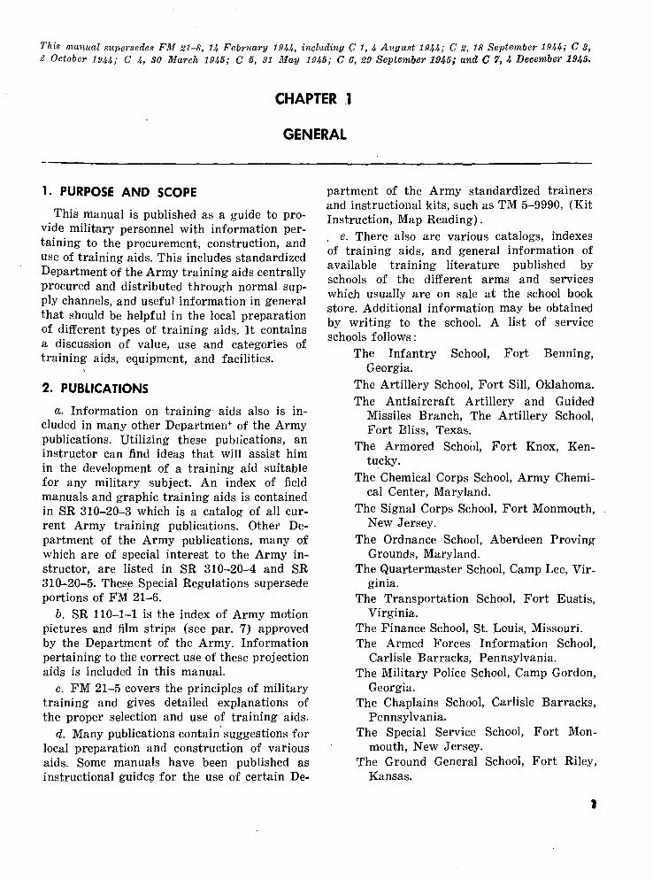
1. PURPOSE AND SCOPE
This manual is published as a guide to pro vide military personnel with information per taining to the procurement, construction, and use of training aids. This includes standardized Department of the Army training aids centrally procured and distributed through normal sup ply channels, and useful information in general that should be helpful in the local preparation of different types of training aids. It contains a discussion of value, use and categories of training aids, equipment, and facilities.
2. PUBLICATIONS
a. Information on training aids also is in cluded in many other Departmen4- of the Army publications. Utilizing these publications, an instructor can find ideas that will assist him in the development of a training aid suitable for any military subject. An index of field manuals and graphic training aids is contained in SR 310-20-3 which is a catalog of all cur rent Army training publications. Other De partment of the Army publications, many of which are of special interest to the Army in structor, are listed in SR 310-20-4 and SR 310-20-5. These Special Regulations supersede portions of FM 21-6.
b. SR 110-1-1 is the index of Army motion pictures and film strips (see par. 7) approved by the Department of the Army. Information pertaining to the correct use of these projection aids is included in this manual.
c. FM 21-5 covers the principles of military training and gives detailed explanations of the proper selection and use of training aids.
d. Many publications contain suggestions for local preparation and construction of various aids. Some manuals have been published as instructional guides for the use of certain De
partment of the Army standardized trainers and instructional kits, such as TM 5-9990, (Kit Instruction, Map Reading). . e. There also are various catalogs, indexes of training aids, and general information of available training literature published by schools of the different arms and services which usually are on sale at the school book store. Additional information may be obtained by writing to the school. A list of service schools follows:
The Infantry School, Fort Benning,Georgia.
The Artillery School, Fort Sill, Oklahoma. The Antiaircraft Artillery and Guided
Missiles Branch, The Artillery School, Fort Bliss, Texas.
The Armored School, Fort Knox, Ken tucky.
The Chemical Corps School, Army Chemi cal Center, Maryland.
The Signal Corps School, Fort Monmouth,New Jersey.
The Ordnance School, Aberdeen ProvingGrounds, Maryland.
The Quartermaster School, Camp Lee, Vir ginia.
The Transportation School, Fort Eustis,Virginia.
The Finance School, St. Louis, Missouri. The Armed Forces Information School,
Carlisle Barracks, Pennsylvania. The Military Police School, Camp Gordon,
Georgia. The Chaplains School, Carlisle Barracks,
Pennsylvania.The Special Service School, Fort Mon
mouth, New Jersey.The Ground General School, Fort Riley,
Kansas.
The Engineer School, Fort Belvoir, Vir ginia.
The Adjutant General School, Camp Lee, Virginia.
/. SR 355-310-1 contains lists and descrip tions of publications, training aids, and serv ices, including—
(1) Discussion material.(2) Film service.(3) Map service.(4) Pamphlets and information manuals.(5) Poster service.(6) Armed Forces Press Service.(7) Armed Forces Radio Service.
Although these regulations were designed pri marily for instructors of the Troop Information Hour Program, information contained therein is valuable to instructors in many fields of military training.
3. DEFINITIONS
a. Training aids consist of all physical ma terials (exclusive of publications and textbooks) which ar prepared especially for the teaching of military subjects or instruction in the utili zation of Armed Forces equipment. Operational equipment will be considered a training aid only when used for training purposes or as a component part of a training device.
b. Training aids can include anything used in training; however, for the purpose of this manual and in order to limit the scope, training aids are classified as follows:
(1) Motion pictures.(2) Film strips, slides, transparencies.(3) Telecasts for training purposes.(4) Recordings.(5) Graphic aids (consisting of printed
matter, such as charts, schematic dia grams, posters, flat illustrations, pic torial literature, and similar items).
(6) Training devices (consisting of three- dimensional aids, such as models, miniatures, "cutaways," mock-ups, and those complex mechanical or elec tronic special devices such as syn thetic trainers, mechanized evaluators,
simulated operational systems and similar items).
(7) Training equipment includes such items as blackboards, chart easels, projection and sound equipment, practice rounds, and certain training equipment listed in tables of allow ances and tables of organization and equipment.
(8) Training facilities consist of perma nent and semipermanent aids to train ing, such as ranges, obstacle courses, and all specially designed training areas.
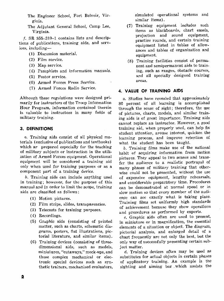
4. VALUE OF TRAINING AIDS
a. Studies have revealed that approximately 80 percent of all learning is accomplished through the sense of sight; therefore, the use of pictures, charts, models, and similar train ing aids is of great importance. Training aids cannot replace an instructor. However, a good training aid, when properly used, can help fix student attention, arouse interest, quicken the learning process, and improve retention of what the student has been taught.
b. Training films make use of the national habit of acquiring information from motion pictures. They appeal to two senses and trans fer the audience to a realistic portrayal of many phases of military training that other wise could not be presented, without the use of expensive equipment, lengthy rehearsals, and considerable preparatory time. Procedures can be demonstrated at normal speed or in slow motion so that every member of the audi ence can see exactly what is taking place. Training films set uniformly high standards of achievement because they show operations and procedures as performed by experts.
c. Graphic aids often are used to present, in miniature or in magnification, the essential elements of a situation or object. The diagram, pictorial analysis, and enlarged detail of a chart frequently are not only the best, but the only way of successfully presenting certain sub ject matter.
d. Training devices often may be used as substitutes for actual objects in certain phases of applicatory training. An example is the sighting and aiming bar .which assists the

soldier to learn the 'correct sight picture. Schematic models reduce the principles in volved to their simplest possible form and bring those principles within the realm of the sol dier's previous knowledge. For example, it would take considerable time to describe the mechanism of the Ml rifle to someone who never has seen the weapon; however, by means of a model, the process would be simplified. Many complex items of equipment consisting of a number of component parts can be shown to advantage disassembled and each part mounted on a display board in a manner that would indicate how a part fits into the assem bled item. Special devices are used in synthetic training and are complex systems normally not produced locally.
5. USE OF TRAINING AIDSa. The proper use of training aids requires
thorough preparation on the part of the in structor. Training aids should be a planned part of the instruction in all subjects for which they are intended. Therefore, the instructor first must be completely familiar with their availability, and their advantages arid limita tions when used singly and in combination. Before using a training film or film strip in a class, the instructor should study it, several times if necessary, in order to become thor oughly' familiar with the contents. He should plan in advance the necessary introduction and discussion that should come before and after the showing of a film. Instructors should con sider such factors as—
Will it fit into the plan of instruction ? Will it help attain the objective of the
lesson? Is it adapted to the group?
b. A blackboard will be found useful both indoors and outdoors for certain kinds of illus trations. Maps or sketches, drawn or developed on the blackboard, help present a clear picture te the class.
c. Charts and drawings made to represent a fact, or an idea, are used primarily to focus the attention of the audience. The drawing should represent the thought so clearly that few words or figures are required.
d. Maps on which operations are indicated should be scaled large enough so that the sym bols used can be seen with ease by students in the back of the room. A map scale of 3 inches to a mile is sufficiently large for use in a room that will hold an audience of 100 students. In using movable symbols, it is desirable for the instruction to have an assistant to move the symbols as the instructor proceeds with his lecture.
6. ADDITIONS AND CHANGES TO MANUAL
a. Training aids become obsolete because of constant changes of equipment, new equipment, and newer methods of presenting military sub jects. To keep abreast of such changes, alert instructors are constantly planning and using new training aids to meet new situations. Sug gestions for new training aids for possible in corporation in this manual should be submitted, through channels, to The Adjutant General, ATTN: Assistant Chief of Staff, G-3.
b. The following must accompany each sug gested training aid:
(1) An 8 by 10 inch glossy photograph, or a clear sketch of the aid.
(2) Plans and specifications of the aid.(3) Description and type of aid.(4) Recommended use of aid:
(a) Place, for example, classroom, shop, outdoors, etc.
(b) Number of students aid will serve.
(5) Additional information:(a) If produced locally, give cost and
production agency. (6) If produced commercially, give cost
and source, if known.
3

CHAPTER 2
AUDIO VISUAL AIDS
Section I. MOTION PICTURES, FILM STRIPS, RECORDINGS, AND REPRODUCER UNITS
7. MOTION PICTURES AND FILM STRIPSa. SR 110-1-1 contains a complete list of
motion pictures and film strips. See paragraph 2b.
b. Information pertaining to the procure ment of films and film strips may be obtained from the Signal Corps Film Library. These libraries, in addition to serving the army areas, also serve the Organized Reserve Corps, Na tional Guard, and Reserve Officers Training Corps.
c. Instruction pertaining to the use of films and film strips as projected training aids is contained in FM 21-5.
d. Information pertaining to the use of pro jection equipment is contained in SR 110-30-5. Illustrations of this type of equipment are shown in section IX, chapter 4, this manual.
8. RECORDINGS AND REPRODUCER UNITSa. Probably the most commonly used record
ing for training purposes is the slow playing 3314 rpm record which accompanies the sound film strip.
b. Recordings of Army bugle calls by the Army Band are available on request through channels to The Quartermaster Depot, Phila delphia, Pennsylvania.
c. Battle sound recordings, including sounds of artillery and small arms fire, explosions, and airplanes, add realism to training, maneuvers, and Aggressor exercises. They are available at film libraries.
d. Security violation records of dramatized incidents of radio security violations also are available at film libraries.
e. Foreign language records are issued in kits with manuals which can be used as self- study aids. For further information regarding this type of recording, refer to the catalog of the United States Armed Forces Institute (USAFI), which also lists records on short hand and music appreciation.
/. Recorder-reproducer units for sound re cording and instructional purposes are listed in appropriate tables of allowances. A wire recording unit and play-back machine is in cluded in the sonic equipment used by Ag gressor Forces, and is discussed in FM 30-104.
Section II. GRAPHIC AIDS
9. GENERAL
a. Graphic aids include all diagrammatic, schematic, or pictorial drawings, paintings, and photographs. Large-size charts can be made, using a balopticon projector by tracing the illus tration or object on a blackboard or chart paper. This method of reproduction is economical and can be accomplished in a short period of time. Any opaque or still picture can be made into a lantern slide and projected onto a screen. Transparencies can be prepared by photog raphy or art work on glass or film in standard 2 by 2 inch or 31/4 by 4 inch size. Still pictures
may be projected by reflection in an opaque projector if they are of the proper size, approxi mately 6 by 6 inches.
b. Department of the Army graphic train ing aids (GTA's) comprise military instruc tional charts and posters (singly or in series) and certain printed devices reproduced as visual aids. These GTA's are listed in SR 310- 20-3 and can be procured through adjutant general channels.
c. Graphic portfolios contain a special type of chart series consisting of a relatively large number of charts printed on heavy durable

paper, with explanatory notes printed on the reverse side of each chart for use by the instructor.
d. Posters are designed primarily as re minders and supplements to class instruction. To achieve maximum benefit, they should be displayed where personnel regularly pass or gather. Displays should be changed frequently.
e. Sample printed devices include such aids as the cardboard replica compass, paper pro tractors, and scales.
/. Military maps used for instructional pur poses by personnel of the Reserve components may be procured at nominal cost directly from book stores at army installations. Other in formation regarding maps may be secured by writing the Superintendent of Documents, Government Printing Office, Washington 25, D. C. Training literature pertaining to the various phases of military instruction may be purchased also through military book store facilities. Maps used for instructional purposes by military installations may be procured through local supply channels from Depart ment of the Army Map Service, Washington 25, D. C., and from Director, U. S. Coast and Geodetic Survey, Washington 25, D. C.
g. Weatherproofing of graphic training aids may be accomplished by spraying the surface (both sides) with clear outside white varnish. Lacquer also may be used for this purpose, keeping in mind that too lieavy a coat of either varnish or lacquer will tend to stiffen or harden the paper, resulting in the cracking of the sur face. This is one of several methods of weather- proofing which has proved satisfactory.
10. LOCAL PRODUCTION OF GRAPHIC AIDSa. There are various ways and methods by
which simple line drawings can be made. An ordinary window shade can be utilized very well for this purpose simply by drawing on one or both sides of the shade whatever dia
gram, sketch, or chart is desired. Successive phase charts can be constructed in this manner. By pulling the shade either up or down, the subject highlighted can be illustrated rapidly with economy of motion. Right line or simple line, drawings can be made easily on wrapping paper and displayed at the appropriate time during an instructional period. For more com plicated pictorial or schematic -drawings, trained artist or draftsman personnel should be employed. Local training aids departments usually employ civilian or military personnel for this purpose.
b. Silk screening process is an excellent method whereby chart reproduction can be accomplished. Details pertaining to facilities needed, methods of operation in detail, includ ing production shortcuts, are outlined in TM 28-325. For the procurement of silk screen process equipment, refer to appropriate tables of equipment.
c. The following criteria should govern the local production of charts:
(1) The size must be suitable for the class. Charts that are too small to be seen easily by the entire Class should not be used for group instruction.
(2) The detail should be selected carefully. Only that which is essential to the purpose of the chart should be in cluded.
(3) Lettering should be legible. Letters 2 inches high are minimum for legi bility at 75 feet.
(4) Color or shading should be used to emphasize the important points. This use of color has proven that student observation and learning are greatly aided.
d. Various types of graphic training aids are illustrated in section II, chapter 4, of this manual.
Section III. TRAINING DEVICES
11. THREE-DIMENSIONAL AIDS
There are innumerable devices or models ranging from the simple marksmanship sight
ing bar to the complicated and expensive gun nery trainer that can be classified best as "three-dimensional" aids or training devices. Relatively few of these (such as instructional

kits and trainers) have been standardized for issue by the Department of the Army; most of the aids described in the illustrations fol lowing are intended as suggestions for local preparation. For convenience, they are grouped in the following categories:
Working models Displays and exhibits Kits and trainers Miniatures Terrain models Miscellaneous devices.
Various types of three-dimensional aids and
training devices are illustrated in sections III through VIII, chapter 4, this manual.
12. SALVAGE
a. Many items turned in for salvage can be used in constructing training aids. Such items as motors or other vehicle parts are readily adaptable as training aids, and can be secured from the unit salvage officer.
b. The salvage officer should be contacted as a possible source for miscellaneous material that can be used to facilitate the construction of training aids.

CHAPTER 3
TRAINING EQUIPMENT AND FACILITIES
13. TRAINING EQUIPMENTTraining equipment includes projection and
sound equipment which is available from film libraries or is listed in tables of allowances (par. 36). Data on use of film strip projector and 16-mm motion picture projector are con tained in SR 110-30-5. Instructors should be familiar with the uses and limitations of 16-mm sound film projectors, opaque projectors with film strip complete with 2 by 2 inch and 3*4 by 4 inch slide attachments, record players for film strip and phonograph recordings, over head projectors and public address systems.
Associated with projection equipment are screen and shadow boxes. Suggestions for local construction of various types of training equip ment will be found in section IX, chapter 4.
14. TRAINING FACILITIESTraining facilities include such permanent
or semipermanent training aids as large mock- ups of equipment, demonstration areas, physi cal training areas, reaction or infiltration courses, and specially designed training areas. Information on lay-out and construction of many such facilities will be found in TM 9-855.

CHAPTER 4
ILLUSTRATIONS AND INFORMATION
Section I. GENERAL INFORMATION
15. SCOPE
a. The illustrations and working plans found in this chapter depict various types of training aids designed to aid the present or potential instructor in his planned course of instruction.
b. This chapter does not illustrate nor give complete references to all known aids used in the training of military personnel in the De partment of the Army, but covers, in part, suggestions for training aids that can be adapted to suit present needs.
c. Information pertinent to the types of aids shown in each section of this chapter precedes
the illustrations and is given to clarify the pur pose and scope for which the aids are designed.
16. TRAINING AID CENTERS
Training aid centers being established in each Army area are centrally located training aid shops for the construction and production of training aids and distribution of these and Department of the Army training aids through out its own area. Army commanders will issue information pertaining to the training aids available at the centers from time to time.
Section II. GRAPHIC TRAINING AIDS
17. GENERAL
a. The graphic training aid does much to focus student attention, impart knowledge, and aid memory through the use of the sense of sight.
b. SR 310-20-3 lists the available graphic training aids which can be procured through regular publication channels.
c. Graphic training aids can be prepared locally. Steps to be followed in preparing a graphic training aid are as follows:
(1) Decide exactly what is wanted on the aid.
(2) Make a small pencil sketch.(3) Decide whether it is to be drawn with
ink, crayon, or paint.(4) Decide on the type paper to be used.(5) Decide on letter size. Make letters
large enough to be easily seen.(6) Sketch in the contents lightly with
pencil.(7) Draw in the contents with ink, crayon,
or paint.
(8) If ink or paint is used, allow the aid to dry and then clean it with an art gum eraser.
d. This section illustrates various types of graphic training aids and gives information as to their use and their procurement.
18. ILLUSTRATIONS AND INFORMATIONa. Chart, lubrication order (fig. 1). Lubrica
tion orders similar to the one shown are listed in SR 310-20-4, and are available through adjutant general publications channels. A chart of this size can be used to teach lubrication to large classes through the use of a balopticon or it can be issued to individuals for reference and study.
b. Map reading, coordinate scales, and pro tractors (fig. 2).
(1) This is a single sheet approximately 8i/8 by 12% inches, printed on both sides. It is arranged so that, after being cut out, the protractors and co ordinate scales may be used on either side. One side of the protractor is
8

LUBRICATION ORDER11 Ftbruory 1949 (Supenedei WDLO 9-373. 10 FE6 <5|
GUN 90-mm, Ml MOUNT, GUN, AA 90-mm M3
Intervall ere baled on normal operation. Reduce lo compeniata (or abnormal Clean fitrinql before lubricatinq. Lubricate after walnmg.
eltended comm.nwrate with adequate preservation. Clean parti with CLEANER, rifle bore. Dry before lubricatlnq.
Travertin, Vertical Snail OG M Lower Bearing
Trai.n.ng KB,*. rfcruir anit Clip Bf'i'ig Hiuiing Drain
I-I.T..I * utrieait
W PL Eiposed Recoil Slide
W OG Recoil SlideEl...', v ., 10 >. ... (t.
M OG Control Bar Hinge Pin
Rrrof'/ Mechanism I'."/ Plug
RS Recoil Mechanism Gravity Fill
W OG Recoil Slide
W PL Recoil Throttling Valv« Guide
W OG Recoil Slide
M OG Automatic BreechOperating Cam Plunger
M OG Cradle Trunnion Bearing
LEFT SIDE OF GUN AND MOUNT
-KEY-IUBRICANTS
OC- G«£*S£. 00
OH— <1lL. k.d-.-l.c
EXPECTED TEMPERATURES.W" +irF
SB« OS iltl
°M (ifr'V^oi
+ JI F !0 0~F
SDK 01 Hit OC- 00
iit;i IOROI
0 D F. to-40°F.
Sb.c OS u*'
OC 00
• 0-r. .U— OIL .|eg.l l<q>il
»-p...,M-M...K,
Figure 1. Chart, lubrication order.
scaled in degrees; the opposite side is scaled in mils. One side of the coordi nate scale indicates yards; the other side, meters.
(2) This training aid is to be used by personnel receiving instruction in map reading and is handy to facilitate work with maps, both indoors and out doors. This training aid is listed in SR 310-20-3 as approved Department of the Army GTA 5-12.
c. First aid training model (fig. 3).(1) This skeletal model showing the bone
and blood system of the human body
is used in the instruction of first aid technique.
(2) A human figure is drawn on a piece of plywood board S 1̂ feet by 6 1/2 feet by i/4 inch, and then jigsawed out. The bone structure and blood system then is drawn in, resulting in a life- sized figure illustrating the important areas and pressure points where first aid measures are most applicable. This realistic type of training aid em phasizes to a better degree important facts in the teaching of first aid technique.

5i § § § i I I I I M I I I l_=
COOIDINATE SCALES
YARDS
« «_%.
COORDINATE SCALES
METERS
! OWI -I
oooi H
•*&• ooor
ooos
0009
0001
COM —;
OOM
OOO'OI
... 1000-=
* ""••
§ i § iFigure 2. Map reading, coordinate scales and protractors.
(3) If plywood is not available, stiff card board can be utilized, with a wooden frame in the rear to give it support when in an upright position. It easily can be constructed locally.
d. Forceful message chart (fig. 4). An effec tive combination of diagram and text to pre sent a clear and forceful message.
e. Plain language chart (fig. 5). This chart fulfills the requirements of including only the essentials, used with plain letters large enough to be seen by the whole class, simple wording, and specific informational purpose.
/. Humorous message chart (fig. 6). An ex ample of the use of a cartoon, which appeals to the sense of humor and emphasizes a potent lesson for instructor and student alike.
g. Slot type (fig. 7). Subject cards are bound at top and bottom with strips of wood slightly longer than the slots through which the cards pass; at beginning of class, only the bottom strip is visible. Instructor pulls each card through the slot at the appropriate time.
h. Pull-off type (fig. 8). Successive steps in
instruction are covered with strips of heavy paper glued, tacked, or taped to the chart and pulled off by the instructor to expose the de sired material.
i. Window shade type (fig. 9). This chart is lettered on an ordinary window shade; each subject appears as the shade is pulled down.
3. Hinged type (fig. 10). Each subject card is hinged at the top, folded up and held in place by a tack or pin until released by the instructor.
k. Conventional signs and symbols cards (fig. 11).
(1) This suggested training aid is a set of forty 22- by 28-inch cards showing conventional signs and symbols. These cards are bristol board with a sign or symbol painted on each side. The set can be placed in a wooden rack for carrying and display.
(2) This aid is used in a classroom or sheltered outdoor area. It is designed for use with a group of 200 men or less. The aid can be produced locally from cardboard and painted in the
TO

Figure 3. First aid training model.
unit silk screen shop or training aids department. These cards can be pro duced at nominal cost. Symbols for re production can be found in FM 21-25, FM 21-26, or FM 21-30.
I. Pocket reference cards (fig. 12).(1) A card which folds to a size of 314
by 4V£ inches presenting, in concise form, full information about detec tion of, and protection against, the six different types of chemical agents. General instructions on care of the gas mask, the use of eye ointment, pro tective ointment, and decontamination also are shown.
(2) This pocket-size card can be carried by military personnel at all times, for ready reference and for self- instruction.
(3) Recommended basis of distribution: one per individual.
(4) These cards, listed in SR 310-20-3 as GTA 3-2, may be secured through usual adjutant general publications channels.
m. First aid (fig. 13).(1) This training aid contains a series of
approximately 50 charts of illustra tions and graphic material, 44 by 30 inches. On the reverse side of each page, supplemental instruction is provided.
(2) This graphic portfolio is to be used for instructional purposes in first aid. It is particularly applicable for out door use, but can be used indoors as well. The sequence should be followed closely throughout the entire train ing process. Use is most effective when limited to groups the size of a platoon or smaller.
(3) Instructions for the preparation of an easel are included on the reverse side of the pages.
(4) This is GTA 8-1, as listed in SR 310- 20-3.
n. Rifle, Ml, disassembly mat (fig. 14).(1) The disassembly mat shown in figure
14 is one of a number of similar mats for small arms weapons that have been standardized by the Department of the Army.
(2) These mats can be used in the in struction of weapon disassembly and assembly.
(3) Disassembly mats are Department of the Army graphic training aids and can be obtained through normal adju tant general publication channels.
o. Chart, photographic mural (fig. 15). This type of chart mates excellent training aids. These can be reproduced in some training aid shops at service schools, also in Signal Corps or commercial photographic laboratories.
11

HOW MUCH TO TEACH
PEACE TIME
MUST KNOW
WAR TIME
WHAT A LESSON PLAN WILL DO FOR YOU
LGUIDE FOR PREPARATION 1GUIDE FOR PHYSICAL
ARRANGEMENTS3.GUIDE FOR ACTUAL TEACHING4.PROMOTE UNIFORMITY5.ASSIST SUBSTITUTE
INSTRUCTORS6.GIVE SELF CONFIDENCE
Figure 5. Plain language chart.
Figure 4.' Forceful message chart.
Figure 6. Humorous message chart.
12

1ST SUBJECT
Figure 7. Slot type cards.
1ST SUBJECT
20 SUBJECT
3D SUBJECT
4TH SUBJECT
Figure 9. Window shade type card.
1ST SUBJECT
Figure 8. Pull-off type card. Figure 10. Hinged type chart.
13

Figure 11. Conventional signs and symbol cards.
14

•GAS" 1 HOW TO DETECT 3 PROTECTION AND FIRST AID
Figure IS. Pocket reference cards. {Possible enemy chemical warfare agents.)
15

Figure 13. First aid.
16

Figure H. Rifle, Ml, disassembly mat.
Figure 15. Chart, -photographic mural.
17

Section III. WORKING MODELS
19. GENERAL
a. Working models are constructed to illus trate mechanical functioning and to teach nomenclature.
6. Many working models are constructed in scales greater than actual size, permitting large groups ©f students to observe the functioning process of the mechanism.
c. Models such as the Browning automatic rifle functioning frame (fig. 17) have the vari ous parts painted different colors to facilitate identification of each part.
d. The working models shown on the follow ing pages are suggested training aids con structed by skilled craftsmen using locally available materials and salvage parts.
e. It must be kept in mind that the overuse of working models will tend to emphasize un duly the functioning of mechanisms, thereby minimizing many other important factors of operation. For example, a wooden working model of the Browning automatic rifle will not show the true cause of stoppage, misfire, or the resulting action of gases. The best working model always is the actual piece of equipment. Working models, at best, are exaggerated fac similes of the actual object constructed specifi cally to teach nomenclature and the mechanical
operation of functioning parts to large groups of students.
20. ILLUSTRATIONS AND INFORMATION
a. Automatic pistol, cal. .45, M1911 and M1911A1 (fig. 16). This is a wooden working model used in teaching nomenclature and func tioning of the pistol. It is constructed of scrap lumber to a scale of approximately 7 to 1 and is mounted on a piece of plywood 43 by 82 inches. See FM 23-35.
b. Functioning frame, Browning automatic rifle, cal. .30, M1918A2 (figs. 17 and 18).
(1) The purpose of this functioning frame is to demonstrate the functioning of the operating parts under the action of the expanding gases and recoil spring.
(2) The frame and backboard are made entirely of wood. The pieces that hold the operating part of the rifle are mounted on the backboard. The oper ating parts can be manipulated within the frame. The operating parts which include the slide, the bolt and bolt lock, the bolt link, the bolt link pin, the hammer, the hammer pin, and the trigger guard group are disassembled
Figure 16. Automatic pistol, cal. .45, M1911 and M1911A1, working model.
18

Figure 17. Functioning frame, Browning automatic rifle, cal. .30, Ml 918AS.
from the rifle, then reassembled in the functioning frame. The recoil spring and recoil spring guide also may be assembled in the frame, if desired.
(3) Figure 17 shows how this function ing frame can be utilized for instruc tional purposes in outdoor classes. Plans for the construction of the func tioning frame are shown in figure 18.
c. Planetary gears mock-up (fig. 19). This is an 8- by 30-inch working model showing func tions of the planetary gear. It can be con structed locally from salvaged material.
d. Micrometer model (fig. 20). This wooden model of a micrometer is used to teach students the proper method of reading and using the gage.
e. Piston mock-up (fig. 21).(1) This wooden working model demon
strates the functioning of the piston and crankshaft of a valve-in-head en gine. It also can be used to advantage to show the action transpiring during each phase of the firing cycle.
(2) Of fairly simple construction, it can be used to facilitate understanding of
19

ACTION OF OPERATING PARTS
SET-UP TO DEMONSTRATE ACTION OF OPERATING PARTS
WOODEN FRAME TO REPRESENT THE RECEIVERFigure 18. Working drawing, Browning automatic rifle
functioning frame.
Fig lira 19. Planetary gears mock-up.
automotive engine nomenclature and functioning. It is recommended that contrasting colors be used in painting.
(3) Approximate cost should not exceed$5. Additional information regardingconstruction can be obtained fromThe Armored School, Ft. Knox, Ky.
/. Distributor, cam angle, mock-up (fig. 22).(1) This training model is used to illus
trate the working parts of the cam angle and points.
(2) A dial is added to the model, indicat ing the angle at the opening of the gap.
(3) It is used in a classroom to instruct 30 students or less, and can be made to any desired scale by skilled crafts men. The approximate price of the wood and metal parts is $9.
20

Figure 20. Micrometer model.
g. Plastic distributor (fig. 23).(1) This training model is used to illus
trate the working mechanism of the distributor.
(2) Built from a plastic block, this dis tributor can be placed in actual oper ation and will show to the student the various functioning parts of the distributor.
h. Gunner's quadrant, Ml (fig. 24). By use of this enlarged wooden model, effective instruc tion in nomenclature and the use of the gun ner's quadrant can be given to relatively large groups. Elevations can be set on the arc and
CUTAMMT VALVEHN- HEAO ENGINE
Figure 21. Piston mock-up.
Figure 22. Distributor, cam angle, mock-up.
21

Figure 23. Plastic distributor.
Figure 24-. Gunner's quadrant, Ml.
micrometer. This aid can be constructed to any desired scale by a skilled craftsman using di mensions of the actual model. A bubble can be formed in the tube by partially filling it wth No. 10 oil to the desired level. Materials used are scrap lumber, paint, small springs, and clear fluorescent lamp for the vial. See TM 9-2300.
i. Angle of site scale and micrometer with level bubble (fig. 25). This model, built to any desired scale, can be used to teach the procedure in setting off angles of site on the elevation
scale M9. Materials used are scrap lumber and a clear fluorescent lamp for a vial. The bubble can be formed in the same manner as for the gunner's quadrant (h above). See TM 9-2300 for complete information on the angle of site scale and micrometer.
j. M15 firing lock model (figs. 26 and 27).(1) This aid is a wooden working model
used to demonstrate the functioning of the M15 firing lock. It is a 36- by 48- by 1/2-inch plywood panel, with en larged plywood replicas of the parts of the firing lock mounted in their proper relation. The stationary parts are attached to the panel by screws. The moving parts are held in place by the stationary parts when the com plete model is assembled.
(2) The springs necessary to make the model function can be made from heavy wire. A weight, attached to the firing pin sleeve by means of pulley and cord, is used to return the model part to its neutral position. The moving parts of the model should be painted different colors to assist in the explanation of functioning.
(3) The entire model is mounted on an "A" stand made of 2- by 2-inch boards. It can -be used in classrooms or for outdoor classes with groups of 50 men or less. It can be produced locally. Ma-
22

Figure 25. Angle of site scale and micrometer with level bubble.
terials needed are 24 square feet of i/^-inch plywood, wood screws, paint, and 30 feet of 2- by 2-inch lumber. A diagram of specifications is shown in figure 27.
k. Plastic working model, Browning machine gun, cal. .30, M1919A4 (figs. 28, 29, and 30).
(1) This aid consists of plastic and metal and is used to demonstrate the func tioning of the interior parts of the
machine gun. All of the gun which obscures the action of these parts dur ing functioning is made of plastic. The interior parts are the actual parts from the machine gun. The plastic parts are made to scale so that the metal parts will operate smoothly in the housing. This type aid can be
Figure 26. M15 firing lock model.Figure 27. Diagramatic plan for construction of the
Ml 5 firing lock working model.
23

Figure 28. Plastic working model, Browning machine gun, cal. .30, Ml 919 A^.
Figure 29. Top view, Browning machine gun, cal. .30, Ml 919'Alt-
e 30. Side view, Browning machine gun, cal. .30, M1919A4.
24

Figure SI. Portable flame thrower pressure regulator, mock-up
made to demonstrate the functioning of small arms.
(2) This aid cannot be produced locallybut must be procured from special (2) training aid shops of service schools or must be contracted for locally. The aid can be used indoors or outdoors with 15 students to each machine gun.
I. Portable flame throiver pressure regulator, mock-up (fig. 31).
(1) This mock-up is used as an aid inteaching classes the construction and (3)
functioning of the dome-type pressure regulator of the portable flame throw er M2-2.Materials used are scrap lumber, wire screening, salvage rubber hose, and an old spring of suitable size. The scale of the mock-up shown is 5 to 1; however, it may be made any desired scale. For comparison purposes, two cutaway pressure regulators are shown in the illustration.The jars on the left contain fuel mix-
Figure 32. Gun group, portable flame thrower, M2-3.
25

Figure S3. Wooden working model of pressure regulator M2-2.
tures in various percentages. Those on the right contain napalm and paptizer.
m. Gun group, portable flame thrower, M2-2 (fig. 32). This is a cutaway model used in teach ing the action of the fuel valve and ignition (2) head of the portable flame thrower. The model can be made from a salvage gun group by re moving the ignition head cover plate and cut ting away portions of the valve grip, grip sup port, and valve body.
n. Pressure regulator M2-2 (figs. 33 and 34). This model can be constructed to any desired scale by skilled craftsman, at an approximate (3) cost of $25.
o. M2-2 portable flame throiver pressure reg ulator (fig. 35).
(1) This is a working model used in teach ing adjustment of the dome-type pres sure regulator of the flame thrower M2-2. The fuel tanks, air cylinders, (4) pressure regulator, high pressure line
and pressure gage are from the M2-2 flame thrower. The 1/4-inch copper tubing used to connect the pressure regulator to the fuel tanks is approxi mately 21/9 feet long.The tubing and the couplings can be procured locally. The adjusting wrench shown to the left of the fuel tank is an Alien wrench, welded onto a cut off end of an ordinary screw driver, and is used for adjusting needle valves Nos. 1, 2, and 3 shown in the illustration.The fuel tanks are filled with 4 gallons of water up to the level indicated by the light colored paint on the cylin ders. The equipment can be mounted with strap iron or heavy gage wire onto a piece of plywood approximately 55 inches high and 64 inches wide.All the materials and parts except the copper tubing are salvaged parts from
26

Figure SL. Large diagram and exploded pressure regulator, mounted.
M2-2 PFT PRESSURE REGULATOR
Figure 35, Working model, pressure regulator portable flame thrower

HIGH PRESSURE LINE
LOW PRESSURE LINE
ADJUSTING WRENCH
Figure 36. Pressure regulator, portable flame thrower M2-2 (hasty demonstrator).
a portable flame thrower. T/A 20-2and appropriate tables of organizationand equipment prescribe basis forissue of the portable flame thrower.
p. Pressure regulator, portable flame thrower,M2-2 (hasty demonstrator) (fig. 36).
(1) This is another type working model used in teaching adjustment of the dome-type (groove) pressure regula tor, using only the regulator, pressure line, gage, and air cylinder.
(2) The regulator, high pressure line, and safety head are taken from a portable flame thrower. The gage is a No. 0- 500-pound gage. The low pressure line and couplings can be procured locally. The adjusting wrench is the same as that shown in figure 35. A commercial
air cylinder connected to the high pressure line is used to indicate pound pressure.
(3) Models can be constructed from ma terials at hand, ranging from the pre cise model constructed by the post machine shop (fig. 31) to the model constructed from available salvage material shown in figure 36.
q. Sectionalized .50-caliber machine gun. (fig. 39).
(1) As an aid to teaching the functioning of the Browning machine gun, caliber .50, this cutaway model may be used. It consists of a sectionalized machine gun mounted on a box containing a small electric motor. The motor causes an arm to move back and forth along
28

Figure 37. Plastic model, flame thrower MS. (Approximate cost, $90.)
Figure 38. Plastic model of Browning automatic rifle, cal. .30, M1918A2. (Approximate cost, $200.)
the long axis of the machine gun. This arm is connected to the bolt handle of the machine gun and causes the bolt to move back and forth to simulate firing. Dummy rounds of ammunition
are used to complete the entire cycle of firing.
(2) It is recommended that this aid be used only when the class does not ex ceed 15 students. The entire section-
29

Figure 39. Sectionalized .50-caliber machine gun.
alized machine gun, complete with motor and actuating arm, can be pro cured through ordnance supply chan nels. (Gun, machine, caliber .50, Browning M2, HB, turret type, section- alized training aid (AR)93G980550. Manufactured by the Reflectone Cor poration, Stamford, Conn.)
r. Grenade launcher model (figs. 40 and 41).(1) This model consists of a portion of the
Ml rifle, M7 launcher, valve screw, Ml adapter, and fragmentation grenade.
(2) The Ml rifle is mounted on a plywood backboard. The weight of the model as sembled is supported near the center by a removable dowel in the back board.
(3) The rifle, launcher, and grenade are made of wood and metal. The adapter, made of metal, is used to demonstrate the procedure for firing fragmenta tion grenades with the M7 launcher.
s. Firing mechanism, cat. .30 M1917A1 Browning machine gun (figs. 42 to 50). This training aid is designed to teach, through dem onstration, the trigger action, cocking, and automatic firing process of the caliber .30 Browning machine gun. Figures 43 through 50 give the specifications for the construction of each working part. Materials can be pro cured from salvage or local supply. Each work ing part should be painted a different color to emphasize its function. This model can be built by unit or post carpenter, using the specifica tions shown in each figure.
Figure 40. Dimensions of grenade launcher model.
30

Figure 41. Grenade launcher model.
Figure 42. Wooden working model of firing' mechanism of the caliber .30 M1917A1 Browning machine gun.
FRONT VIEWH————————————————————————————8'—————-——————————————————————H
SIMULATED INSIDE OF BOLT
FIRING PIN-
I SEAR PIN AND SPRING
I—TRIGGER•SEAR•COCKING LEV£R
Figure 43. Wooden working model of firing mechanism to demonstrate trigger action, cocking, and automatic fire of the Browning machine gun, caliber .30, M1917A1.
31

BACKBOARD
2X4
BLOCK WITH INSERT FOR TRIGGER PIN
GROOVED BOARDS I X2 FOR TONGUE BOARD BEHIND BOLT TO RIDE IN.
Figure 44- Construction of backboard for trigger action. BOLT
GROOVE FOR TONGUE _ _ - . ON BOLT SO SEAR MAY .2" L_ SLIDE UP AND DOWN.
ILOCK WITH INSERT FOR COCKING LEVER PIN
Figure 45. Construction of bolt.
FIRING PIN
SPRING IS ATTACHED BEHIND BOLT AND ACTSAS FIRING PIN SPRING TO SEND FIRING PIN
FORWARD AFTER ITS RELEASE FROM SEAR NOTCH.
PEGS EXTEND THROUGH.SLOTS IN BOLTDIAMETER 3%
SOLID WOOD WITH EXCEPTIONOF CUT-OUT SLOT WHICH
EXTENDS THROUGH FIRING PIN.
Figure 46. Construction of firing pin.
32

BOLT FITTING INTOROUND BLOCK ON
MG BOLT
COCKING LEVER
Figure 47. Construction of cocking lever.
SEAR SPRING AND PIN
Figure 48. Construction of the sear spring and pin.
SEAR
T,
Figure 4!). Construction of the sear.
TRIGGER
BOLT EXTENDS THROUGH TRIGGER AND FITS IN BLOCK ON BACKBOARD.
Figure 50. Construction of the trigger.
33

Figure 51. Wooden working model showing headspace of the Browning caliber .30 machine gun, M1917A1.
t. Headspace of Browning machine gun cal. .30, M1917A1 (figs. 51 to 59). This model is constructed from the specifications given in
figures 52 through 59. It is built from materials procured from salvage or local supply. See FM 23-55.
FRONT VIEW
34
Figure 52. Wooden working model of recoiling parts to demonstrate head- space adjustment, locking and unlocking of the breech of Browning ma chine gun, caliber .30, M1917A1.

BACKBOARD
GROOVE FOR TONGUE BOARD IN REAR OF BOUT TO SLIDE IN. BOLT PROJECTING FROM BACKBOARD
Vi" FOR CENTER-GROOVED BOARD. INREAR OF LOWER REAR PROJECTIONS.
TO SLIDE ON.
GROOVED FOR TONGUE BOARDS IN REAROF BARREL EXTENSION AND BARREL
TO SLIDE IN
Figure 53. Construction of backboard for recoiling parts.
BOLT
SIDE VIEW OF BOLT SHOWING GROOVED BOARD ON BACK
Figure 54. Construction of bolt.
BARREL EXTENSION
,y,"——»)
INDEX FOR HEADSPACE ADJUSTMENTS2V«"
-" I-— -= ----- - ____ _ _ J_. I- _-----""" L.5'/,-
U_—12%'
Figure 55. Construction of the barrel extension.
35

BREECH LOCK
3'/2
BOARD WITH PROJECTIONS TORIDE IN GROOVES AT REAR OF
BARREL EXTENSION
Figure 56. Construction of the breech lock.
BREECH LOCK CAM
2V.
Figure 57. Construction of breech lock cam.
NAIL FOR ADJUSTMENTS ON INDEX
2%" WING NUT AND BOLT THAT PASSES THROUGH
SLOT IN BARREL EXTENSION FOR
HEADSPACE ADJUSTMENT
Figure 58. Construction of the barrel (side vieiv).
7 5"
2%'
!=>
TOP VIEW OF BARREU
Figure 59. Construction of the barrel (top vieiv).
36

Figure 60. "441" training aid (front view).
Figure 61. Rear view of "441" training aid.
u. "441" training aid (figs. 60 and 61). This training aid, particularly adaptable for the small unit instructor, is an excellent medium to describe the 441 sight setting used to "zero- in" the M1917A1 machine gun on the 1,000-inch range. The top bar in figure 60, which is
painted red, represents the line of aim. The top position in the slot (fig. 60, at demonstra tor's left hand) represents the line of aim with the sights set at zero. The solid white line represents a line in prolongation of the axis of the bore. The broken white line represents the trajectory of the bullet. To substantiate the teaching, the board is turned around, as shown in figure 61. It can be constructed any desired size by the unit carpenter.
v. Working model of rear sight leaf, cal. .30 machine gun (fig. 62). This working model, constructed by the unit carpenter, is' used to teach machine gunners proper adjustments of the sights. See FM 23-55.
Figure 63. Working model of rear sight leaf of caliber .SO machine gun.
37
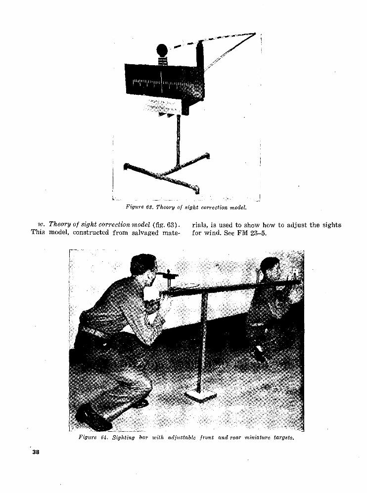
Figure 63. Theory of sight correction model.
w. Theory of sight correction model (fig. 63). rials, is used to show how to adjust the sights. This model, constructed from salvaged mate- for wind. See FM 23-5.
Figure 64- Sighting bar ivith adjustable front and rear miniature targets.
38

x. Sighting bar with adjustable front and rear miniature targets (fig. 64). This aid is used to teach the correct adjustment for wind age and elevation. In addition, a group of shots can be registered by the firer on the hinged pad in front of the rear sight. When
the correct sight picture is obtained, the hinged pad is swung up to the rear peep sight. The student then registers the shot by inserting a pencil through the peep sight. This procedure is repeated until a group of shots have been registered.
Figure 65. Working model of vernier plotting/ board.
Figure 66. Plastic model of machine gun, caliber .30 (approximate cost, $250.)
39

y. Vernier plotting board (fig. 65). The vernier plotting board M10 working model is constructed to a large scale and used in the
manner illustrated to teach proper usage of the board.
personnel the
Figure 67. Plastic model of rifle, caliber JO, Ml (approximate cost $150.)
Figure 68. Model compass (oversize).
40

z. Model compass (figs. 68, 69, and 70).
(1) This compass is made of plywood, metal, and glass. (Transparent plastic may be used in place of glass.)
(2) It is intended to be used before large or small groups to demonstrate sight
ing, setting azimuths, and other uses of the magnetic compass.
(3) A skilled craftsman can make a model to whatever scale is desired by chang ing the dimensions, proportionately, of the working drawings shown in figures 69 and 70.
Figure (19. Side view, working plans model, lensatic compass.
Figure 70. Model lensatic compass—dimensions for eyepiece, cover, and frame for glass.
41

Section IV. DISPLAYS AND EXHIBITS
21. GENERAL
a. Various displays and exhibits, including cutaway models, are illustrated in this section.
b. Training aids of this nature tend to facili tate, through actual demonstration, teaching of large groups of students and impressing upon them the functioning of various mecha nisms and complete assembly of units or objects.
c. Cutaway models that are made by expert craftsmen are costly. Utilized properly, how ever, they are excellent types of instructional aids. Models shown in this section were made from salvaged and unserviceable parts.
22. ILLUSTRATIONS AND INFORMATION
a. Sniperscope (figs. 71 and 72).(1) The principal components of the
sniperscope are displayed on a board 5 feet by 5 feet which is painted white. The parts are held on the board by nails and may be removed easily.
(2) This display can be used either in doors or outdoors with a class of 100 students. Figure 72 shows the sniper- scope in use. Basis of issue is given
Figure 71. Sniperscope display board.
in TA 20-2, or other appropriate tables of allowances.
6. GMC engine (fig. 73). This training aid is an actual cutaway engine, mounted on a rotating platform. This cutaway engine is an effective aid in teaching the principles of the four-cycle engine, nomenclature, and function ing of various parts. This cutaway model must be constructed by skilled personnel having access to proper tools. Parts for this model can be procured from unserviceable GMC motors. See TM 9-801.
c. Live poiver train, M24 light tank (figs. 74 and 75). A working model, diagrammatically laid out, shows the position, purpose, and func tion of the power units and the power trans mission system of the M24 light tank. This model can be used as a display and for class room instruction of 50 students or less. It was constructed locally of used parts and mounted on a movable platform.
d. Knots and hitches display board (fig. 76).(1) This training aid is used by the in
structor to demonstrate the different ways rope can be tied in order to achieve the best results in each situation.
(2) The board should be painted white with black lettering identifying the examples of each knot. Short strands of ordinary clothes line can be used by the student to tie knots and hitches from a study of each one shown on the display board.
(3) Knots tied by students should be com pared with those on the display board in order that errors may be pointed out and suggestions given for correct ing them. The examples on the board were made of 3/4-inch manila hemp that was procured locally. The board can be made of salvaged lumber.
(4) It can be used indoors and outdoors with groups of 50 men or less. See FM 5-35 for illustrations on knots, lashings, and rigging.
e. Sectionalized y^-ton truck cutaway (figs. 77, 78, and 79).
42

Figure 72. Sniperscope in use.
INTERNAL COMBUSTION GMC .
Figure 73. GMC engine. Figure 74. Live power train, M24 light tank, front view.
Figure 75. Live power train, M24 light tank, oblique view.
43

KNOTS AND HITCHES
Figure 76. Knots and hitches display board.
Figure 77, Sectionalized V^-ton truck cutaway.
(1) This training aid consists of an actual 14-ton truck with the body removed and the various units in the power transmission system shown.
(2) The engine can be operated; and, by placing the Sectionalized truck on blocks, the operation of each unit can
be studied. This training aid is used to teach the nomenclature, function ing, and operation of the power train of wheeled vehicles. A model can be made from a salvaged i/4-ton truck.
/. Flywheel and clutch mechanism cutaway (fig. 80).
(1) This training aid consists of an ex posed model of a clutch and flywheel mechanism, together with the clutch pedal for use in measuring clutch pedal free travel. The reason for clutch pedal free travel can be shown clearly on this model.
(2) This aid is used to teach nomencla ture, functioning, operation, adjust ment, and abuses of the clutch assem bly. This model can be made locally, from a salvaged clutch and flywheel assembly, by a mechanic or machinist.
g. GMC transmission cutaway (fig. 81).(1) This training aid is an actual trans
mission cutaway to expose the prin cipal parts of the transmission assem bly. This model is used to assist in tracing the flow of power through the transmission in the different gear positions.
44

Figure 78. Sectionalized y^-ton truck cutaway.
Figure 79. Sectionalized y^-ton truck cutaway.
45

Figure 80. Flywheel and clutch mechanism, cutaway.
(2) It also is used in classroom instruction to explain nomenclature and operation of the transmission assembly. Proper methods of removing and replacing the transmission cover also can be demonstrated. This training aid can be made locally, from a salvaged transmission assembly, by a machinist or mechanic.
h. Automotive fuel system display (fig. 82).(1) This is a working model and display
schematically laid out, showing the purpose, functioning, and relation ship "of the major units comprising the automotive fuel system. This model was constructed locally of used parts and mounted on plywood.
(2) A small electric motor furnishes the power to drive the cam shaft mounted behind the board to actuate the fuel
filter. The float bowl and the carbu retor are cutaway and windowed with plastic to observe the flow of fuel and the operation of the various parts. The fuel pump is constructed of plastic. A vacuum gage and a pressure gage have been added to the system to facilitate instruction.
i. Automotive electrical system (fig. 83). (1) This is a combined working model
and display board schematically laid out showing the various electrical circuits, their functions, and relation ship to one another. This model, con structed locally from salvaged parts,
Figure 81. CMC transmission cutway.
46

Figure 82. Automotive fuel system- display.
may be used in instructing groups of approximately 50 students.
(2) A small electric motor provides power to drive the generator and distributor. Each electrical circuit is identified by different colored wiring. Additional ammeters have been installed in the various circuits to facilitate instruction.
j. Cam and lever steering gear cutaway (fig. 84).
(1) This training aid is an actual cam and lever stearing gear cutaway to show the operation of the principal parts. The steering column has been shortened to facilitate handling.
(2) This aid is used to teach the nomen clature, functioning, operation, and adjustments of the steering gear. This aid can be constructed locally from a salvaged steering column.
k. Final drive cutaway (fig. 85).
Figure 83. Automotive electrical system.
47

Figure 84. Cam and lever steering gear cutaway.
(1) This cutaway model of a final drive can be utilized as a training aid to show how the differential and final drive assemblies operate. Each axle is cut off at the end and fitted with a crank, enabling the instructor to operate the aid manually.
(2) This model can be made locally from salvaged banjo-type axles. It is mounted on an improvised steel stand made from a salvaged wheel.
I. Exploded radial engine (fig. 86).(1) A radial engine, showing one cylinder
and all other parts of the engine in
Figure 85. Final drive cutaway.
its relative position, is mounted on a table 3 feet by 10 feet. This display is valuable for instructing classes of 50 students or less in tracing the in ternal lubrication system.
(2) It also shows the five sections of the engine, the necessary mountings, the drives, and the diffuser or .supercharger passages. It can be used also in teach ing assembly, disassembly, function ing, and nomenclature of the radial engine. Similar displays can be made for any type engine and used in the same manner. This aid can be con-
Figure 86. Exploded radial engine.
48

Figure 87. Portable hardware display board.
structed from unserviceable engine parts.
m. Portable hardtuare display board (fig. 87).
(1) This is a folding case which, when opened, can be utilized and set up as
a display board. It contains the vari ous types of hardware used in camp structures with name and descriptions of each piece indicated. The display can be attached permanently to the classroom wall or designed to be closed and carried as indicated in the illustration.
(2) It is used for the purpose of teaching the proper nomenclature of hardware items. It may be made in whatever form is suitable and convenient to show such items as are available.
11. Tire troubles (fig. 90).(1) This is an excellent method of teach
ing vehicle drivers the common faults of tire troubles. Items can be procured from salvaged tires. Lumber can be obtained from unit supply or salvage.
(2) Explanation cards under each exam ple on the display panel contain the following:
Example of ... Diagonal smaller tire or oldgrown tubes break. • placed in new tire.
Cause: "Overload."Example of ... Ply separa
tion.
Example of ... Loose cord due to running tire when flat.
_____ Cause: "Neglect." Continuedoperation after tire was flat.
Cause: Running tires underin-flated. Example of ... Tread sepa-
Example of ... Stretched ration- _____ tube.
Cause: "Impact." Overinflation increases susceptibility to this condition.• Example of ... Neglected cut.
Cause: Failure to inspect and make proper repairs.
Example of ... Tubes chaf ing._____ Cause: Overloading.
Cause: Large tube placed in Example of ... "X" Break. Cause: Inside break in tire.
o. Mines and booby traps (fig. 91). Mines and booby traps can be displayed in the manner illustrated. The display can be used to point out parts and construction of the items shown. Items can be procured from salvage or other sources and arranged in any manner designed.
p. Sighting and aiming (fig. 92). This board is used in conjunction with mortar fire train ing. It is of simple design and can be con structed by any unit carpenter, using salvaged lumber and paint. See FM 23-90.
q. Communications panel board (fig. 93). This enlarged panel of an electrical board is a valu
able training aid in teaching the nomenclature and functioning of an electrical system. This type panel can be adapted to other Signal Corps equipment to facilitate instruction to larger groups.
r. Camouflage garnish patterns (fig. 94). This aid is used to demonstrate the various pat terns recommended for garnishing a camou flage net. It is of simple construction and may be constructed locally from scrap lumber and parts of a camouflage net. If a camouflage net is not available, a tennis net or volley ball net may be used, or wire may be strung qn a board.
49

Figure 88. Ammunition and gun disassembly display panels of the Browning machine gun.
Figure 89. Disassembly display panels showing rifle, caliber .30 Ml; carbine, caliber .30 Ml; pistol, automatic, caliber 45 M1911; rockets, grenades, and launchers; submachine gun, caliber 45 MS; BAR, caliber .30 M1918A2. (Approximate cost of display board, $170.)
50

M tt H••P 1W ^^
Figure 90. Display panel showing tire troubles.
51

MINES & BOOBY TRAPS
MAKE YOUR Cwacc PACK A PUKH !
Figure 91, Mines and booby traps display board.
52

Figure 92. Sighting and aiming display board.
53

Figure 93. Communications panel board.
Figure 94. Camouflage garnish patterns.
54

Section V. KITS AND TRAINERS
23. GENERAL
This section illustrates kits and trainers, some of which have been standardized and are available for issue under appropriate tables of allowances. Trainers such as the tank com munication trainer, figure 108, are actual size replicas of equipment.
24. ILLUSTRATIONS AND INFORMATION
a. Bridge model training kit, panel bridge, M2, Bailey type (figs. 95, 96, and 97).
(1) The bridge model training aid kit, panel bridge, M2, Bailey type, scale 8 to 1, is an approved Department of the Army training aid. It is designed for demonstrational use by instructors and also for practical work by stu
dents in classes having 30 to 40 students. The model is not designed for use in capacity or physical tests. It weighs about 300 pounds including chests (fig. 95). The kit provides enough equipment to construct 10 bays (equivalent to 100 feet) of triple- single construction with launching nose, 9 bays (90 feet) of double- double construction, 6 bays (60 feet) of triple-double construction, 8 bays (80 feet) of double-triple construc tion, and 6 bays (60 feet) of triple- triple construction. Enough additional equipment is supplied to construct 2 bays of ramp. Lengths of the model bridges are restricted by the amount of the equipment provided.
Figure 95. Bridge model training kit, panel bridge, M2, Bailey type.
55

Figure 96. Front view, panel bridge, M2, Bailey type.
Figure 97. Side view, panel bridge, M2, Bailey type.
(2) Assembled model bridges have an over-all width of 2 feet 6 inches with out the footwalks, and 3 feet 2 inches with them. They vary in length from 1 foot 3 inches to 15 feet, and in height from 9 inches to 2 feet 3 inches. Figures 96 and 97 illustrate the 7 pos
sible types of standard truss con struction that can be used in assem bling the bridge.
(3) Each bridge model kit is packed in three compartmental chests, (fig. 95). To aid the instructor in his presenta tion, one of each of the major compo-
56

Figure 98. Bridge model, floating bridge M4A2.
nent parts is painted an identifying color.
(4) This kit is authorized for issue in ap propriate tables of allowances. For information on the use of the kit, see TM 5-277K.
b. Bridge model, floating bridge M4A2 (figs. 98, 99, and 100).
(1) The bridge models shown above and on the following page are constructed from materials contained in a kit similar to that in figure 95. It weighs about 534 pounds, including chests. The equipment in the kit can be used to build models of several different types of bridges either with or with out trestles.
Figure 99. Floating bridge, M4.
57

Figure 100. Raft section.
(2) The dimensions of the finished models are as follows: M4 model bridge over all width of 4 feet 11 inches and a total length of 13 feet 2 inches (with out trestle) ; the assembled M4A2 (class 50) model has an over-all width of 2 feet 9 inches and a length of 10 feet 7 inches. The raft section (fig. 100) also can be constructed from the kit. The bridge model kit is packed in 5 compartmental chests, similar to those displayed in figure 95. This kit is authorized for issue in appropriate tables of allowances. For complete assembly instructions, see TM 5-261K.
c. Timber trestle bridge model (fig. 101). (1) The kit, including chests, weighs
about 210 pounds. When erected, its over-all dimensions are: length 11 feet 4 inches; width 2 feet 10 inches; height 1 foot 2 inches. Completely assembled, it consists of 9 spans. The major assemblies are two abutments,
eight intermediate trestle bents, and the superstructure.
(2) Each bridge model kit is packed in two compartmental chests similar in design to those shown in figure 95. It is designed for demonstrational use by instructors and for practical work by students in classes of from 30 to 40 students.
(3) In order to aid the instructor in his presentation, one of each of the major parts is painted an identifying color. Three large-scale charts in corre sponding colors, showing the con struction details of the three types of major assemblies, are provided in a separate container that accom panies the model kit. This kit is authorized for issue under appropriate tables of allowances. For instructions in assembly of the kit, see TM 5-260K.
d. Portable machine gun punchboard (figs. 102, 103, and 104).
Figure 101. Timber trestle bridge model, class 50/80.
58

(1) This punchboard is a 4- by 7-foot panoramic sketch of an impact area, showing targets, prominent terrain features, gun positions, and ranges. The instructor, by moving the simu lated beaten zones to any portion of the target that he is discussing, teaches the technique of engaging various types of targets.
(2) Plans for construction of the punch board are shown in figures 103 and 104. A terrain sketch is made on the plywood front, and nails are driven in at desired places on the board to represent flanks and inner portions of targets. The elliptical-shaped pieces of plywood (resembling typical beaten zones) are attached to weighted ropes which pass through the two numbered gun positions at the bottom. Each beaten zone facsimile has a small hole drilled in the center, enabling the simulated beaten zones to be hung on nails in the desired locations.
(3) All materials used can be obtained
locally at an approximate cost of $5. For information about the technique of engaging targets, see FM 23-55.
509
UlFigure 103. Diagram of punchboard frame, front view.
5-PLY
Figure 102. View of punchboard. Figure lOlf. Side view of punchboard frame.
59

Figure 105. Photo interpreter kit, F2.
e. Photo interpreter kit, F2 (fig. 105). This kit can be used by photo interpreters, G-2 sec tions, and other personnel engaged in photo interpretation work. The basis of issue is one kit per photo interpreter team. The illustration shows the items contained in the kit.
/. Artillery trainer, MS (fig. 106).(1) The trainer is a unit comprised of
four miniature guns mounted on mini ature carriages, each of which carries a panoramic telescope and the neces sary mechanisms for moving the car riage in deflection and in elevation. The ammunition consists of com
pressed air as the propellant and a 1-inch commercial steel ball as the projectile. The guns may be employed singly or in groups of 2 to 4, depend ing upon the nature of the training.
(2) The trainer can be used in many kinds of artillery training, one of which is conduct of fire. For additional infor mation on training uses, operation, preparation of target area, etc., see TM 6-225. Appropriate tables of al lowances cover the basis of issue of the artillery trainer.
g. Gunnery training kit, M36 (fig. 107).
60

Figure 106. Artillery trainer, MS.
(1) This standardized kit is used in field artillery training and consists of the following parts:
(a) Packing box. The packing box is constructed of wood and reinforced metal. The ends, bottom, and top are solid. The sides are formed, by the blackboards. The interior of the box is grooved and fitted so that all components of the kit are held se curely in place. The approximate dimensions are 76 by 23 by 39 inches.
(b) Smoke puff terrain board. This board, when assembled is 6 by 6 feet. Construction materials mainly are 1,4-inch plywood and 1,4-inch tempered masonite. For pack ing purposes, it folds to 6 .by 3 feet. It is fitted together with wooden dowels. The scale of the terrain is 6 inches to 100 yards, making the area covered by the ter rain screen 1,200 by 1,200 yards. The board is constructed so that the range from the gun position to the center of the board is 4,000 yards. The gun position may be moved to any position up to an 1,800-mil target offset on either side of the observer.
(c) Blackboard grid sheet. This black
board is gridded in white with a scale corresponding to the gradua tions of the plotting equipment. The blackboard forms one side of the packing box. The material is tempered masonite. Its dimensions are 6 by 3 feet.
(d) Blackboard, computers record. This blackboard provides permanent computer's record form for fire di rection center training. Its dimen sions are 6 by 3 feet.
(e) Blackboard, plain. This blackboard is for general instructional use. It forms one side of the packing box. The dimensions are 6 by 3 feet.
(f) Blackboard, recorders sheet. This blackboard provides a permanent recorders sheet form for firing bat tery instruction. The dimensions are 6 by 3 feet.
(g) Plotting equipment. Three sets of plotting equipment are included in this set. All items are constructed from tempered masonite. • Each set consists of—
1 range deflection fan, 40 by 18%inches.
1 protractor, 24 by 12 inches. 1 coordinate scale, 11 by 11
inches.

1 straightedge, 31 by 2 inches. (h) Aiming circle, piece and panoramic
sight.1. The aiming circle consists of four
thicknesses of Vs-inch tempered masonite. Six model aiming cir cles are included in the set. The four thicknesses are the base; the lower motion, which operates in dependently; the upper motion, which also operates independent ly ; and the compass needle, which moves only with the base and is always pointing "north."
2. The piece and panoramic sight con sists of three thicknesses of Vs- inch tempered masonite. Twelve pieces and panoramic models are included in the set. The three thicknesses are the base; the piece which bears the sight index and operates independently; and the graduated circle, or pano ramic sight, which also operates independently.
(i) Vernier board. The vernier board provides a simple means of train
ing artillery survey personnel in reading both horizontal and verti cal angles on a transit. This model is four feet long.
(j) Military slide rule and easel. The military slide rule is universally applicable to all field artillery units. This model is six feet long. The easel provides a means for display ing and demonstrating the graphi cal firing tables, graphical site table, or the military slide rule. It also provides a solid backing for any of the blackboards.
(k) Graphic site table and firing table. The graphic site table and firing table provides instruction of per sonnel in the use of these two tables. These models are six feet long.
(2) This kit appears on appropriate tables of allowances. A similar kit may be purchased from the Artillery School, Fort Sill, Oklahoma, through the Book Department, at a cost of approxi mately $250.
h. Tank communication trainer (fig. 108). • (1) This training device is constructed as
Figure 107. Gunnery training kit, M36.
62

Figure 108. Tank communication trainer.
(2)
an aid in tank communication instruc tion. Pipe i/2-inch in diameter is used to build a simulated working model of the interior of a tank. The pipe is welded to conform to the general appearance of seat positions and frame.The intercommunication system and radio is added to the device. It is used
Figure 109. Machine gun dial.
indoors or outdoors, with 50 students for conference, and 5 for practical work. It can be constructed locally at any unit motor pool or shop, using five 14- or %-ton truck seats, 80 feet of 1/2-inch pipe, 30 feet of 2-inch pipe, and four 4-inch casters.
i. Machine gun dial (fig. 109).(1) The training aid shown is an enlarged
machine gun dial, 4 feet in diameter. A steel rod represents the standard index and is screwed into a specially drilled hole (ordnance project) in the cradle pintle block. The rod is station ary. The dial can be moved or kept stationary.
(2) It can be used in the classroom or outdoors with a maximum of 200 students.
(3) The dial can be made locally of masonite or other similar wall board.
j. Driver's depth perception test (figs. 110 and 111).
(1) This test can be used as a training aid to teach safety rules and determina tion of approximate distances of
63

Figure 110. Driver's depth perception test.
^-STATIONARY
t=Hk— s7-^
i IH —
i BA PULLIES |
DRAW UNE g|
| 1=y^=y-^MOVABLE .
c
"I '" r|. -7 4 1
DRIVER'S SCHOOL DEPTH PERCEPTION
TESTAPPROX COST
,*• 15 TO 20 DOLLARS LOCALLY CONSTRUCTED
FRONT VIEWSIDE VIEWFigure 111. Schematic diagram of driver's depth perception test.
64

Figure 112. Auxiliary aiming point mock-up.
— Bfe"—— —8Va'— — B'/o'-* ——6V —
- CLASPS -——— 36' -
TOP
vehicles approaching and passing one another.
(2) By attempting to aline both miniature vehicle models correctly on the testing board, the potential driver can deter mine exactly how two approaching vehicles appear when abreast of each other, and how to judge, from the appearance, just when and at what distance he should observe certain safety measures,
(3) This test, designed for indoor use, can be constructed locally from spare parts and salvage lumber. Pulleys and rope are used. One student operates the trainer.
k. Auxiliary aiming point mock-up (fig. 112).
(1) This aid is employed in mock demon- tration of the auxiliary aiming point method of firing under conditions of poor visibility. The enlarged rear sight is 31/2 times larger than the standard sight. A rod attached to the front and rear sight slide indicates the line of
DETAIL OF FILM COMPARTMENTS WITH HINGED COVER
BOTTOM
-36"
Ik- 3/8" AND 3/4" PLYWOOD AS INDICATED
—IIV4"——. ——10 —
Figure 113. Training aid and publication carrying kit.
65

aim, and extends 5 feet forward of the gun. A second rod, 5 feet long, pro truding from the muzzle, indicates the trajectory.
(2) It can be used in the classroom or out doors for a maximum of 100 students. The target area can be changed pe riodically to represent different ter rain and situations. Scrap masonite or plywood can be used and scenes painted on the surface.
I. Training aid and publication carrying kit (fig. 113).
(1) This is a compact case for carrying training aids, projection equipment, and publications. This cabinet has space for manuals and other publica-
' tions, training films and film strips, projectors, graphic portfolios, and a projection screen.
(2) Rabbet-joined edges provide protec tion against moisture. The training aid and publication carrying kit can be constructed inexpensively by any handy craftsman, following specifica tions in figure 113. Compartments may be changed to fit different combina tions of training aids and publications.
m. Antiaircraft machine gun trainer, M9 (figs. 114 and 115).
(1) An electrically controlled, pneumatic
(2)
device, similar in dimensions to the caliber .50 water cooled antiaircraft machine gun. The trainer fires plastic pellets on a 1:30 scale range, simulat ing the time of flight of a caliber .50 bullet under actual firing conditions. Each set includes two guns, two sound units which provide battle sounds and
RA PD 76065
Figure 114. Antiaircraft machine gun trainer, Ml).
-50 FEET-
CONTROL UNIT
-ZO FEET-
.4-TARGET PLANE
TARGET TOWING REELS \
REEL BASE j\
BACK DROP-
- 15 TO 20 FEET-
PELLET COLLECTOR FLOOR CLOTH
;N"pVfLEA\CO M pTESSOR NA ' R HOSE FL °° R UNE "
CONTROL UNIT BASE
Figure 115. Schematic lay-out of antiaircraft machine gun trainer, M9.
66

Figure 116. Gas identification set, Ml.
simulate blast and recoil, a com pressor, and a target system. (Sound units, compressor and target system not shown.) Complete data on this device are contained in TM 9-221 and TM 9-1221.
n. Gas identification sets (figs. 116 and 117). The .gas identification sets are known as "sniff sets" and are used for the training of troops in the identification of various chemical agents. They can be procured through local Chemical Corps supply channels.
Figure 117. Gas identification set, M2.
Figure 118. Kit, chemical agent detector, M9A1 (ready for carrying).
o. Kit, chemical agent detector, M9A1 (figs. 118 and 119). A set of materials, including de tector tubes, reagents and air sampling pump used in the training of troops in the detection and identification of chemical agents. Units authorized this kit in tables of allowances may obtain it through Chemical Corps supply channels.
p. Kit, instruction, map reading (fig. 120)., Full information for assembly and use of this kit may be obtained from TM 5-9990. Basis of issue is shown under appropriate tables of allowance.
67

Figure 119. Kit, chemical agent detector, M9A1 (ready for contents).
q. Aggressor commander's kit (fig. 121). The kit shown in figure 121 is used by the delegated "Aggressor" commander to aid him in setting up and organizing an "Aggressor" unit. It in cludes the following items (the numbers corre sponding to those in the picture) :
(1) Aggressor flag, white, 4 by 6 feet, with green equilateral triangle 21/2 feet high in the center; used to iden tify Aggressor Commander's head quarters or his vehicle.
(2) FM 30-103, "Aggressor Army Order of Battle" (3 copies) ; reference and study manual.
(3) FM 30-102 "Handbook on Aggressor Military Forces" (3 copies) ; reference and study manual.
(4) FM 30-101, "The Maneuver Enemy" (5 copies) ; reference and study manual.
Note. FM 30-104, "Aggressor Army Representation, Operations and Equipment," will be included also.
(5) Aggressor documents used by the Ag gressor forces for the testing and training of United States forces in
(6)
(7)
the correct processing of intelligence documents through the proper intelli gence channels. Documents included are—
Pass.Permanent pass.Personal letter.Sample page from notebook.Sample page from diary.Commendation.Message.Strength report.Administration order.Company roster form.Casualty reports (tags).Medical Corps collecting point tag.Operation order.Overlays (4 assorted).
Message form blanks used by the Aggressor forces in the same mariner as the United States forces use the .M 210-A Message Book. Soldier's Identification Book, to be carried by Aggressor soldiers.
63

TOUR INTERVAL 100 FT.
\ H&O'O
Figure 120. Kit, instruction, map reading.
(8) Carrying case—a wooden case 5 by 12 by 18 inches (inside measure ments) designed to hold all items of the kit for the purpose of storing and transporting.
(9) Stamp pads and ink for use. withrubber stamps.
(10) Rubber stamp sets and rubber stamps. The rubber stamp sets are for mark ing Aggressor uniforms; the "secreto" stamp and "official seal" stamp are for marking documents.
The basis for issue for these items are one per division or one per separate unit of regimental strength or larger. Requisition for the Aggres sor commander's kit should be forwarded to Commanding General, The Ground General School Center, Fort Riley, Kansas, Attn: Aggressor GHQ.
r. Smoke puff terrain board (figs. 122 to 142).
(1) This type of training aid is used as a substitute for artillery service prac tice in teaching conduct of fire pro-
69
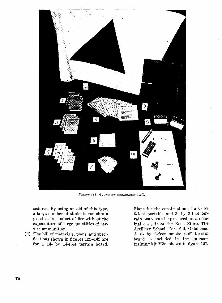
Figure 121. Aggressor commander's kit.
(2)
cedures. By using an aid of this type, a large number of students can obtain practice in conduct of fire without the expenditure of large quantities of ser vice ammunition.The bill of materials, plans, and speci fications shown in figures 122-142 are for a 14- by 14-foot terrain board.
Plans for the construction of a 6- by 6-foot portable and 3- by 3-foot ter rain board can be procured, at a nom inal cost, from the Book Store, The Artillery School, Fort Sill, Oklahoma. A 6- by 6-foot smoke puff terrain board is included in the gunnery training kit M36, shown in figure 107.
70

BILL OF MATERIALSNO.
REQ'D CUT SHEET PIECE NO.
SADDLE2
18
3/4" X 3- 1/2" X 14"1-1/2" X 3-3/8" X 14"1-1/2" X 10
PlywoodYellow PineR.H.W.S.
123
TRACK1122
1111
122222
11152
134
202
' H/2"XIH/2"XI2' Yellow Pine1-1/2" XI 1-1/2" X 14'3"
3/4" X 3-1/2" X 35"Butt HingesYellow Pine
1 -3/4" X 3- 1/2" X 5-3"|-3/8"X5-|/8"X3' — 2"
5/8" X 3-5/8"#6l"X63/4"Xl"XI6'
3/4" XI" XI 4'25/32"X3-5/8"X67"
X96"
3/8" XI- 1/2" X 7' -2"|-|/2"X3-I/4"X7'
7/l6"X 3-1/4" XI 1-7/8"2"
CUT AND PLACE AS SHOWN IN
7/16" X3~I/4"X 48-3/16"3/4"X5"X5"
„
1-3/4" X 10I/4"X9"X7'
Dowel -MapleDrawer PullF.H.W.S.Yellow Pine
u uII M
II II
PlywoodWhite PinePlywoodCasters
PLANS
White PinePlywood
u
F.H.W.S.Upson Board
45678910II121314151617181920212223242526
Figure 122. Bill of materials for saddle and track.
71

SCREEN FRAME2222
112
124
50ft.22
111
6sf.45
3 - 1/2" X 3- 1/2" XI 4'3-|/2"X3-l/2"XI3'— 9"1/2" X 3/4" XI 3'^- II"
Fir •H
Yellow Pine1/2" X 3/4" X 14'# 14 or 16 — 15' X 15'I"XIO"X23"
1/4 X 43/4 ROLLER1/4"
Wire MeshYellow PineTurnbuckleAwning PulleyScrew Eye
tt 6 Galvanized Wire2~I/4"X3-I/4"X6' — 2-1/2" Yellow Pine
" X 5'— 8-1/2"
5/8" X 1-1/4" Dowel — MapleI"X5"l-5/8"X3-5/8"X8"1/4"
White PineHail ScreenSpongesPipe Cleaner
272829303132333435363738394041424344
BACKGROUND12
12
12
12
32
1/4" XI 2" X 14'1/4" XI 2" X 7"I/4"X6" XI 4'1/4" X 6" X7'3/4"XII-l/2"XI4'
Upson BoardII II
II it
II II
White Pine3/4" XI 1-1/2" X7'3/4" X 2- 1/2" X 9'3/4" X 2- 1/2" X 4' — 5"
|-3/4"X 10
ii n
F.H.W.S.
454647484950515253
Figure 123. Screen frame and background.
72

PUFF BOX11
4422
282
1NO.
REQ'D112222
111122
122
18
11
|-|/2"X5"X9-l/2" Yellow Pine|-|/2"X7"X9-l/8"
Rubber Bulb3/4"X2-|/l6"
1/2" X 1-3/4"I/2"X3"X9"I"X5I/2"X3"X3"
Dowel — Plastic11 Maple
White PineF.H.W.S.White Pine
1/2" X5"X 8-5/16"
PUFF
1/4" XI 2"3/4" X 3/4" X 2- 1/45/16" IN.DIA.
l/2"XI-l/2"X9-5/83/8" X 3/4" X 3- 1/4"
BOX CONTINUED"Welding RodIron BarWashersWhite PineMapleEye Hooks
3/8"X9-5/l6"
1-3/4" X 10Dowel- MapleR.H.W.S.Washer
3/4"X2"X 8-1/8I/2"X2"X7"
3/4" X 6I/2"X8-I/8"X24"
PlywoodYellow PineR.H.W. S/Yellow Pine
I/2"X 1-1/2" X 24"I/2"X2"X9"
3/4" X 3/4" X 9 -3/4"1 OUNCE CAP.
3' 6 MM. O.D.9'
White Pineii II
VailsGlass TubingRubber Hose
545556575859606162
PIECE NO.63646566676869707172737475767778798081
Figure 124- Puff box.
73

RANGE BEAM
212
1242222
14
18122
1-3/8" X7"X 3'1-3/8" X7"X 12'
3/16" X 6" X 3'
Yellow PineH N
Upson Board3/16" X 6" XI 2'3/4"X2"X3'
1/16" X 5/8" X 6"l"X7
|-5/8"X3-l/2"XI6"3"
3/4" XI- 1/4" X 3'
Yellow Pine"U" StrapR.H.W.S.Yellow PineHingeWhite Pine
3/4" XI -1/4" XI 2'6"
|-3/4"X3-5/8"XIO'l"X6
2"XIO1/4" X 4"
Strap HingeYellow PineF. H.W. S.F.H.W.S.Dowel-Maple
82838485868788899091929394959697
PILLOW BLOCK816
1 -5/8" X 1-3/4" X 3- 1/2"3"XI2
OakR.H.W.S.
9899
CARRIAGE44
112
12222
142
112
3/4"X 11-3/32" DIA.3/4" XI 2-13/32" DIA.4" XI" DIA.4"x4"X41 -4"4"X4 M X4'— 8"4"X4"X4'— 8-3/8"
1-1/2" X 2-1/4" X 39"1 -1/2" X 3- 1/4" X 6 6"1 -1/4" X 2-1/2" X 30"|-|/4"X2-|/2"X33"
1/2" X 4"1/2" X 5 -3/4" X 7"
PlywoodII
Dowel-BakeliteFir
II
II
Yellow Pineu II
u u
u II
Dowel — Maple
White Pine3/4"X3-5/8"X7"4"X6"X 25-1/4"
4" X6"X 28-1/8" •
3/8"X#6
FirM
M.B.
1001011021031041051061071081091101 II112113114115
Figure 125. Range beam, pillow block, and carriage.
74

BILL OF MATERIALNO.
REQ'D18
1 Gro.44
50ft.125
5 Ibs.1 Gal..
1/2 ••
1118
. 88
3 ft.9 ft.44
2 Gal.1 Ib.
52
R.H.W.S. 3"XI2F.H.W.S. 1-3/4" X 10HEAVY DUTY, 5" STRAP HINGESBROAD BUTT HINGES 3"#10 WIRE3-1/2" TURNBUCKLE1" AWNING PULLEYS2" PLATE CASTERS, SWIVEL TYPEASSORTED NAILS AND TACKSCLEAR VARNISHTURPENTINEI/2"X24" ROUND DOWEL STOCK, HARDWOODI/4"X24" ROUND DOWEL STOCK, HARDWOODl"XI8"ROUND DOWEL STOCK, HARDWOOD OR BAKELITEWIDE MOUTH GLASS BOTTLES 1 OZ CAP.RUBBER STOPPERS 2 HOLE #6
SOLID #6LIME GLASS TUBING 6 M.M. 0. D.RUBBER TUBING 3/16" I.N.RUBBER BULBS, PIPETTE LARGE H/2"X 2-3/4"MEDIUM SIZE SPONGESASSORTED COLORS, SAWDUSTCASEIN GLUE4"X4"XI4' # 1 COMMON FIR4"X4"XI2' -
Figure 126. Material needed for construction of puff board.
75

111
51
24
1
11
12
4"X6"X 5' "2"XI2"XI4' "
" " X 12' "I"X I2"XI6' "
n nn ii
n n
WHITE PINEl"X 8" X 14' C-SELECT, YELLOW PINE1" X4" X2"X4" X
2
2
"X8 "X
"X6"X
14' ',2 '»18'12'
2"X2"X3' OAK
3/4" X 2'X
i n n n
1 COMMON YELLOW PINE
" " FIRYELLOW PINE
OR MAPLE
4' PLYWOOD3/i6"oR'/4"x48
1256 S**
21
16 SF.
1
16
II f i|
"X84" UPSON BOARDX 72"
16 MESH SCREEN WIRE3/e' X 7" U.S.S. MACHINE HEAD BOLTS W/NUTS3/8 X 2 l/211 "
LEAD ANCHORSV MESH HAIL
3!2"xV8'
12" X^"
'xV
n n n n
FOR 3/g BOLT. IF USED ON CONCRETE FLOOR
SCREENSTRAP IRON
STEEL RODSCREW EYES *
<
4 \*<
<?*•GLA
* :
* 106^-- —————— — ̂RUBBER TUBING
f <-^/f3 —————————— ?\m ~^-~ ft 'fur a 9 a*^^ RUBBER STOPPER 11
IJjJ? ? *5S 1 \
1 ' ' 1 / >
HYDROCLORC ACID
: t
AMMONIl HYDROXI^~%r
"5
)M DE
iS^:
' Figure 127. Material needed for construction of puff board.
76

1«I2' *l WR FLOORINS FDD GUN POSITION LOCATOR HOLES
MUMBtRING Of THE ORAOUATIOMS ON AZIMUTH AND BASt ANGLt KAL(: 15 OPTIONAL
FALSt FLOOR
%'OOWtLL
Figure 128. Floor plan of puff board, showing dimensions.
77

SCHEDULE OF KEY DIMENSIONSSizt Of ' i
TkRBAIN A14' «14'
If "12'10' «10
14 '-O'1Z'-0"lO'-O
&6'-O"7'-0"6'-0"
C12'-0"12'-O"lO'-O"
D3'-0"Z'-O"Z'-O"
t8'-O"7'-O"6'-0"
F7-0"6--m-a-*,,
DEFLECTION SCALt IHOtXLOCATED CENTRALLY
ON CARRIAGE
ROLLINO HMIZON TO bE CUT NOT MORE THAN 6" HIGH
.CURTAIN FROM SALVAGE CANVAS
ALL CASTERS -Z PIVOT60 SADDLE LOCATED OWECTLY BENEATH Tut BASE MINT WHICH SHOULD BE ERECTED IN TKI CENTER OF THE TERRAIN
FALSE FLOOR FOR MN I POSITION LOCATE P. HOUS.1 FILL WITH At MANY « DESIRED.
Figure 129. Specifications and dimensions of puff board—side view.
78

LENGTH NOT OVER Z'-O"
PAINT SKY BLUE
PAINT TO REPRESENT HILLS
X4"UPSON BOARD
NOT OVtq 6" HIGH. CUT TO MATCH AT REAR CORNERS. DROP TO 1" AT FRONT ENDS
«r2 HEIGHT NOT OVER 3"
* 6" BACKGROUND SUPPORT SECURED TO FRAME BY
F.M.W. S.
"1408 * 16 WIRE CLOTH TfcRRAlN
4"x4" FRAME OF TERRAIN
ENLARGED DETAILFigure 130. Specifications for joint and backboard of puff board.
79

RO
OM
W
IDTH
20
OB
SE
RV
ER
A
REA
OB
SE
RV
ER
A
RE
A
FOR
WA
RD
O
BS
ER
VE
R
AR
EA
2250
MIL
S 1A
PPRO
X)
CU
RTA
IN
BELO
W FR
ON
T EDG
E O
F T
ER
RA
IN.
AN
OTH
ER
CU
RTA
IN FR
OM
C
EIJ-IN
G
OF_RO
OM
_ TO_W
ITHIN
_8 _OF
TER
RA
lTfMA
Y~,B
E~ LO
CA
T10
H ElRE
AZ
IMU
TH
-BA
SE
3
SC
ALE
oOB

REAR
-T-X4 TURN BUCKLE
AWNING PULLEYS
RUN BACKGROUND AROUND BACK AND SIDES BUT NOT FORWARD OF THESE POINTS
BASE POINT LOCATED DIRECTLY ABOVE THIS POINT
TWISTED CLOTHES LINE WIRE
I X 10 BRACE TOP AND BOTTOM
-i-X l" NAIUING STRIP ABOVE * BOTTOM EDGE OF 4" X V
PLAN OF FRAME Figure 132. Plan of frame.
81

"oI "(D
SIZE OF TERRAIN
14' X 14*I2'X 12'
ic'xio'
A
14-0"
12' -0"
lo'-o"
B "e'-o"7-0"
6'-O"
<DI
• FLOOR
ELEVATION OF FRAMEFigure 133. Elevation of frame, showing dimensions.

DIM
EN
SIO
NS
SH
OW
N A
RE
OP
TIO
NA
L.
AN
Y C
HA
NG
ES
CA
N B
E M
AD
E T
O M
AK
E
SC
ALE
M
OR
E R
EA
LIS
TIC
.
I""!"
.XX,
:L
L LZ
J
oo
o
o.T
RIM
OFF
SU
RP
LUS
S
CR
EE
N
AF
TE
R T
ER
RA
IN I
S S
TRE
TCH
ED
.
LLO
CA
TE
ON
E H
ILL
IN
CE
NT
ER
A
S
BA
SE
P
OIN
T.
NO
TE:
PA
INT
H
OU
SE
S ft
OTH
ER
B
UIL
DIN
GS
V
AR
IOU
S
CO
LOR
S.
ALS
O
PA
INT
3 O
R
4 N
O. 1
0 S
YN
THE
TIC
S
PO
NG
ES
LI
GH
T,
ME
DIU
M
a D
AR
K G
RE
EN
-S
HR
ED
WH
EN
DR
Y.
SC
RE
EN
5 O
R 6
QU
AR
TS O
F S
AW
DU
ST
AN
D
ST
AIN
V
AR
IOU
S G
RO
UN
D A
ND
V
EG
ETA
TIO
N
CO
LOR
S. F
igur
e 13
4. D
imen
sion
s of
min
iatu
res
used
wit
h pu
ff b
oard
.
CO u

SPONGEVARY FROM
3/8" TO 3/4" DIA-
1/16" DIA. APPLICATOR
MAKE UP A FEW TREES AS INDIVIDUAL TREES WITH TRUNKS AS SHOWN ABOVE
ALTERNATE HILL FRAME NO. 14 OR 16 WIRE MESH OR HARDWARE CLOTH LAPPED AT ENDS TO FORM HILL FRAMES. TIE TO UNDERSIDE OF TERRAIN BEFORE TERRAIN IS STRETCHED ON FRAME
HILL FRAMETO BE TIED TO THE UNDERSIDE OF
WIRE MESH TERRAIN TO FORM HILLS
STEPS IN ERECTING AND DECORATING THE TERRAINJOIN THE EDGES OF WIRE CLOTH.
APPLY THE ROADS.
LOCATE AND SECURE HILL FRAMES TO UNDERSIDE OF WIRE CLOTH.
STRETCH TERRAIN ON FRAME.
CUT OFF SURPLUS WIRE CLOTH AND NAIL ON THE NAILING STRIPS.
APPLY COAT OF VARNISH TO TERRAIN (SPRAY ON).
SPRINKLE VARIOUS COLORS OF STAINED SAWDUST.
SPRAY ANOTHER COAT OF VARNISH.
SCRAPE SAWDUST OFF THE ROADS.
LOCATE BUILDINGS AND CEMENT THEM DOWN.LOCATE AND CEMENT DOWN SMALL PIECES OF COLORED SPONGE FOR TREES.
ERECT A CLEARLY DISTINGUISHABLE OBJECT IN THE CENTER OF THE TERRAIN—(BASE POINT).
Figure 135. Plans for the terrain.
84

THE RANGE BEAM MAY NEED TO BE STIFFENED BY ATTACHING A 2"X4" ON THE UNDER SIDE.
SECTION A-A-CEMENT RANGE a ELEVATION
SCALE TO THIS SIDE.
3/8%.
1/8" DRILL" OIL HOLE
1/2 —
-1-5/8"-
W*f "^
1 | jl 1''H-liIF-**i i — -
jro
t
—— ,3/16"
3/8"-3-1/2'
II -ST"! ^
(•———2-3/4"————| ^-3/16" DRILL
PILLOW BOXFigure 136. Close-up of .hinge joint, showing building details.
85

107) NOTE SECURE WHEEL PILLOW BLOCKS TO FRAME IN ASSEMBLY AND WITH CARRIAGE LINED UPON C OF DEFLECTION ARCS
TOP VIEW OF CARRIAGE
I"DOWEL,LIGHT DRIVE FIT AND GLUE.
2-REQUIRED .....
2-REOUIRED.....
SIDE VIEW OF CARRIAGE
GLUE JOINT -
FRONT VIEW OF CARRIAGE
Figure 137. Plans for building carriage.
86

rH 1 UNDER THE BASErjoiij—
^—»fU.t£ FLOOA WITH HOLES TO RECEIVE DOWEL OF CUN POSITION LOCATER
SECTION A-A
FLOOft-j
SECTION B-B
Figure 138. Construction of terrain base.
87

0> oo
1 -|ey f-
• —
——
——
— i —
— —
——
——
| — -f —
— L.
1 i i
! ^
-M>-
4—^-
*-4-
X x^
t>X r>
FRO
NT
VIE
W
OF
PUFF
BO
ARD
Q1 C
J J
STAG
GER
AS
IL
LUS
TRA
TED
T
SEC
A
-A
SA
DD
LE
FOR
THE
SM
OKE
PU
FF
ELE
ME
NT
NO
TE-
DIM
ENSI
ON
S IN
IN
CH
ES
I-|C
M
r i-
Fig
ure
139.
Add
itio
nal
view
, si
de a
nd f
ront
of
puff
boa
rd t
rain
er.

1/2" DOWEL PIN
/ r I \/2PCS 3/4"X2 X2'-3-l/2
3 STRAP HINGE1/2" DOWEL PIN
1I
FORWARDPOST OF CARRIAGE
RANSE OF4440 TfDSSHOULD BE LOCATED
AT THIS POINT
SIZE OF TERRAINI4'XI4'
I2'XI2'
10' X 10'
A
S'-O"
2'-o"
2'-0"
BI2'-0"
I2'-0"
lo'-o"REAR
POST OF CARRIAGERANSE OF 5040 YDS
SHOULD BE LOCATEDAT THIS POINT
Figure 140. Size of terrain—side view.
89

-TR
AC
K
« l»
8'
SLI
DE
t-'ie
"1
-^x
8'
RA
BB
ET
NO
.6 D
RA
WER
P
ULL
SEC
TIO
N E
-EF
igur
e 14
1. S
ectio
n sp
ecifi
catio
ns f
or t
he p
uff
boar
d tr
aine
r.

LIG
HT
ING
OF
TE
RR
AIN
U
SE
5-
TW
O 4
8 I
NC
H
BU
LBS
-FLU
OR
ES
CE
NT
F
IXT
UR
ES
cm
OFF
SET
FOR
VARI
OUS
RADI
I OF
CURV
ED T
RACK
SR
= o b c d e f 9 h
37'
5/3
2"
21/3
2"
1-23
/64
2-13
/32"
4-1/
16"
.5-5
3/64
T -1
5/16
"10
-23/
64
42'
9/6
4 "
9/16
"1 -
9/32
"2-
9/32
"
3 -5
3/64
5-9/
64"
7"
9-9/
64
I I
W
.T—
—I—
——
—a
J_.M
_.|
I _
I I
I -R
I I
I
^——
!_
'
——
——
—R.
\<t
OF
TRA
CK
LOC
ATI
ON
O
F P
IN
( 5/8
") I
N F
LOO
R.
(T£
IT S
HO
ULD
BE
DIR
EC
TLY
UN
DE
R T
HE
\B
AS
E
PO
INT.
NO
TE:
TH
IS
SC
ALE
S
HO
ULD
BE
PA
INTE
D
OR
OTH
ER
WIS
E
MA
TE
RIA
LIZ
ED
ON
TH
E
FLO
OR
IN
FR
ON
T O
F T
HE
TE
RR
AIN
BO
ARD
.
DE
F.A
RC
DE
FLE
CT
ION
S
CA
LE
Fig
ure
H-2
. D
imen
sion
s fo
r ra
dii
of a
rc a
nd d
efle
ctio
n

Section VI. MINIATURES
25. GENERAL
a. Training aids constructed on a small scale are often helpful in adding realism to indoor training. Two-dimensional aids usually cannot give a realistic picture or representation of objects; therefore, the judicious use of minia tures can be a valuable asset in depicting the component parts of objects.
b. In this section are some miniature models used as training aids.
26. ILLUSTRATIONS AND INFORMATION
a. Gin pole, rigging model (fig. 143). This training aid is a miniature model of a rigging device, known as a gin pole, which is used in hoisting work. Cgnstructed from i/2-inch manila hemp or ordinary clothes line, a metal weight and small tackle blocks, this model is used to demonstrate proper procedures of rigging to groups of 30 men or less. For construction plans, see TM S-225.
Figure 143. Gin pole, rigging model.
Figure 144- Rigging model of shears.
92

Figure 145. Warehouse model.
b. Rigging model of shears (fig. 144). This training model is used to demonstrate the pro cedures employed in the erection of heavy ma chinery or other bulky objects. Materials needed are i/4-inch manila hemp or clothes line, 2 small snatch blocks, and lumber. See TM 5-225 for construction plans.
c. Warehouse model (fig. 145).(1) This training aid is used to demon
strate the proper methods of storing supplies and equipment in warehouses. Models can be built to concur with current types of warehouses at the activities concerned, enabling the in structor to teach the procedures in volved, using miniature models of local warehouses.
(2) This warehouse model was built with i/2-inch plywood for the four sides and the beams. Masonite was used to con struct the roof which is removable or can be attached with small hinges, allowing the roof to swing upward.
(3) This model can be used indoors or outdoors with groups of 50 men or less.
(4) Miniature storage pieces can be rep resented by wooden blocks of various dimensions.
d. Field sanitation equipment (figs. 146 and 147). These miniature models, built to scale, can be used as training aids to show detailed construction of field sanitation equipment. The following items are shown in the illustrations: latrine box with pit, shower bath, baffle-type grease trap, incline plan incinerator, soakage pit, and soakage pit with baffle grease trap. The materials used in constructing these models include scrap lumber, pieces of glass, salvage screening and metal, nails, screws, bits of leather and cord.
e. Range target (fig. 148).(1) This is a miniature movable target
frame utilizing "A" and "D" 1,000- inch rifle targets. This training aid simulates the targets, frames, and stands which are used on standard
93

Figure H6. Angular vieiv of miniature field sanitation equipment.
rifle ranges for practice and record firing. Targets are moved up and down by means of cords which are attachedto each frame. *
(2) This aid is used to acquaint trainees with pit operations showing the mark ing and scoring of targets. This mini mizes confusion and results in a sub stantial saving of time on the range. In addition, this device can be used in assisting trainees to develop proper timing for sustained firing.
(3) It can be made from scrap lumber by a handy man, using the diagram shown in figure 148.
/. Rifle range (fig. 149).(1) This training aid is a "range" built
on top of a sturdy table, 4 feet wide and 5 feet long, with legs cross-braced to insure steadiness. The table top is a convenient height (40 inches) above the floor. The eight movable targets
are made to slide up and down in channels at the back of the range where they are pulled by strings at tached to rings that extend through holes in the front end of the table.
-The red flags which indicate per formance are controlled also from the front end of the table. As the photo graph and diagram indicate, in the foreground of the range are the firing line, the ready line, and assembly area, on which is a realistic miniature tent made from a piece of khaki cloth or other material.
(2) Training in rifle range discipline, be fore actual experience is acquired on the range, can be facilitated by knowl edge gained through the use of minia tures of this nature.
(3) This suggested training aid can be made by a craftsman from salvaged lumber, using the specifications shown in the diagram.
94

Figure 147. Front view of miniature field sanitation equipment.
Figure 148. Miniature range target.
95

Wooden spool acts £_ ~~~~Tss pulley to raise
and lower targets
Grease in itots
\;
TOP Vi£W Side pieceA and B frames move
up aid down grooved slott
12"x 12"Cardboard target (mounted)
on frame
___ Sign simulates land embankment
Figure 148- Miniature range target—continued.
96

Figure 149. Rifle range (miniature).
MINIATURE RIFLE RANGE
TOP VIEW
Figure 149. Rifle range (miniature)—continued.
97

Section VII. TERRAIN MODELS
27. GENERALa. This section shows various types of ter
rain boards and sand tables and how they can be constructed.
b. One method of preparing a terrain board or table is as follows:
(1) Secure a contour map of the area to be reproduced. If no map is available, or if the area is imaginary, a small map should be improvised.
(2) Determine the scale to be used and draw grid squares on the map.
(3) Draw corresponding grid squares to the desired scale on table top or base. It may be necessary to subdivide these grid squares to insure rigidity in the completed surface, in which event, corresponding subdivisions will have to be made on contour map.
(4) Determine elevation at each inter section of grids on contour map.
(5) Cut pegs to scale for elevation of each intersection of grids on contour map and install at corresponding point on wooden base.
(6) Stretch cheesecloth, dipped in thin wallpaper paste (or flour-and-water paste), or sized with varnish, over pegs, tacking the cloth to the lower pegs, and allow to dry.
(7) If paste is used, coat with shellac; if varnish is used, no shellac is necessary.
(8) Mix dry papier-mache with water to about the consistency of custard and spread mixture over cloth with hands or trowel, shaping to suit surface of terrain desired.
(9) Trees and shrubbery may be made of sponges dipped in green ink or paint and buildings may be constructed out of cardboard, wallboard, plywood, or scrap lumber, suitably painted. Small trees may be made from lichen which has been cured by immersion in a mix ture of glycerine and alcohol in equal parts and then colored with green ink or water colors. Shrubbery, trees, etc.,
should be installed on terrain board while papier-mache still is wet. In genuity should be used in obtaining other objects to be used to complete detail of terrain board. For example, miniature cars, trucks, and figures, can be obtained at small cost at novelty stores.
(10) Alternate method of surfacing ter rain board: Mix plaster of paris to a consistency of thick cream. Have ready, newspaper torn into piece 6 to10 inches square. Into the plaster of paris mixture dip pieces of newspaper, one at a time, and apply to cloth foun dation, overlapping each piece, and overlaying several pieces where extra height of irregular contours are de sired. Shellac when dry and finish with011 paint. Only a small amount of plaster of paris should be mixed at one time, since this material sets very quickly.
c. Frequently, terrain models are prepared from aerial photographs or they may be en tirely hypothetical, with the terrain features especially created to fit the particular problem which the display is to illustrate.
28. ILLUSTRATIONS AND INFORMATIONa. Sand table construction and accessories
(figs. 150 and 151).(1) These plans can be used for the con
struction of a portable sand table. The tray and stand are separate, al lowing them to be moved easily. The tray holds approximately four bags of sand. The following is required to build the sand table:
50 feet (running) 2- by 4-inchlumber
17 feet (running) 1- by 5-inchlumber
40 feet (running) 1- by 2-inch lumber
(2) The stand is constructed entirely of 2- by 4-inch lumber except for braces marked "A," which are 1 inch
98

STAND IS CONSTRUCTED
ENTIRELY OF 2" x 4" EXCEPT
FOR BRACES MARKED "A"
WHICH ARE I"x5"
Figure 150. Sand table construction.
99
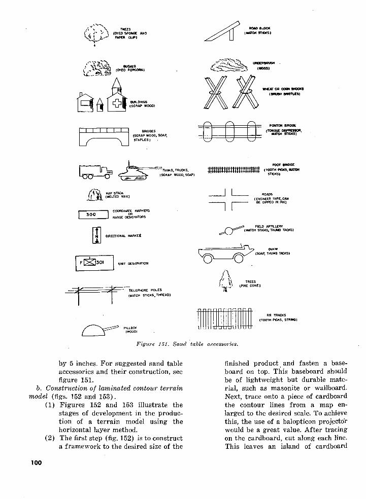
PAPER CLIP)
ROM) BUDCK (MOW STOCSI
BUILDINGS (SCRAP WOOD)
•HEAT 03 CORN SHOCKS (BRUSH BftSTLES)
II I I I——I——L/——\JI I I I I I | BRIDGES(SCRAP WOOD, SOAP, STAPLES)
PONTON BRIOCE
(TONGUE DEPRESSOR,MATCH STICKS)
300
TANKS, TRUCKS, (SCRAP WOOD. SOAP)
POOT BRIDGE (TOOTH PICKS, MATCH
STICKS)
HAY STACK (MELTED WAX)
COORDINATE MARKERSOR
RANGE DESIGNATORS
DIRECTIONAL MARKEj
UNIT DESIGNATION
TELEPHONE POLES (MATCH STICKS, THREAD)
ROADS(ENGINEER TAPE, CAN
BE DIPPED IN INK)
F€LD ARTILLERY (MATCH STJCKS,THUMB TACKS)
OUKW (SOAP, THUMB TACKS)
RR TRACKS (TOOTH PICKS. STRING)
Figure 151. Sand table accessories.
by 5 inches. For suggested sand table accessories and their construction, see figure 151.
b. Construction of laminated contour terrain model (figs. 152 and 153).
(1) Figures 152 and 153 illustrate the stages of development in the produc tion of a terrain model using the horizontal layer method.
(2) The first step (fig. 152) is to construct a framework to the desired size of the
finished product and fasten a base board on top. This baseboard should be of lightweight but durable mate rial, such as masonite or wallboard. Next, trace onto a piece of cardboard the contour lines from a map en larged to the desired scale. To achieve this, the use of a balopticon projector would be a great value. After tracing on the cardboard, cut along each line. This leaves an island of cardboard
100

(3)
for each contour line. When all islands are cut, place them in the correct posi tion, and glue or nail each piece sepa rately. When the top contour layer is in place, cover the entire surface with a thin coating of shellac to keep out moisture.Figure 153 shows the model after the contour layers have been covered with molding plaster or sand mixed with commercial glue. When the plaster or
sand-glue mixture is dry, the entire surface is covered with two coats of paint. Roads and streams are painted in. Basic vegetation, represented by pieces of dyed sponge or lichen, is glued in place. From then on, it is merely a matter of adding buildings, bridges, and any other miniatures desired, resulting in a finished ter rain model presenting a realistic appearance.
Figure 152. Framework of laminated contour terrain model.
Figure 153. Framework covered with molding plaster.
101

DRAWRIGHT LEFT ROAD BANK BANK FORK
TOPOGRAPHICAL CREST
MILITARY
STEEP SLOPE
HORIZONOR
SKY LINE
Figure 15U. Topographical terms chart.
c. Topographical terms chart (fig. 154). This suggested training aid is a 4- by 7-foot piece of %-inch plywood with the topographical fea tures and military terms painted on the panel. It is used in map reading instruction to acquaint the student with topographical terms. It can be used outdoors or in a classroom. It is designed for use with a group of 200 men or less. Ap proximate cost, $5 per chart. Examples of various other terrain and panoramic views may be obtained in FM 21-25 or FM 21-26.
d. Hasty terrain model (fig. 155).(1) The ingenious use of an issue blanket,
a piece of burlap, canvas, or other readily available material, can result in an excellent terrain model. Models can be based on maps, aerial photo graphs, or current information se cured by direct observation of the ter rain, or by patrols. They are lighter and set up more easily than sand tables, can be changed whenever neces sary, and are capable of the greatest variety.
(2) Figure 155 illustrates how an ordi nary issue blanket can be utilized for this purpose. Miniature models of tanks, railroad tracks, houses, and woods can be made from scrap lum ber. Designation and symbol cards representing units and activities can be drawn on small squares of card board and used over again.
(3) The hasty terrain model, as depicted here, does not represent an actual tac tical situation and is not meant to do so. It is used only to show how models and miniatures are adaptable to this particular type of training aid. Hills have been made by lumping material (such as sand, newspaper and dirt) under the blanket. Woods are repre sented by dyed pieces of sponge (see fig. 151). The line of departure shown is a piece of engineer tape. Ordinary rope can be used for this purpose. Railroad tracks are constructed from chicken wire.
102

Figure 155. Hasty terrain model.
(4) This model can be used to representactual terrain for instruction of troopsin battle formations, for briefingtroops in the field on impendingtactical problems, and for critiques.
e. Tank gunnery training aids. The trainingaids shown in figures 156 through 164 are usedin teaching conduct of fire to tank crews ofarmored units.
/. Terrain board (fig. 156). The terrain board shown in figure 156 is constructed as follows:
(1) A painted 6- by 4-foot board is mounted horizontally about 3 feet above the floor.
(2) An aiming circle or binoculars are placed at the same height and' 400 inches from the center of the board.
(3) The longitudinal center line of the board is determined and sketched in lightly.
(4) The aiming circle or binoculars are positioned so that the line of sight through the vertical center of the reticle is along the longitudinal line previously determined as in (3) above.
(5) Successive angles of 10 mils are meas-
4'x6' '
TERRAIN BOARD
REPRESENTS 100 YARDS
REPRESENTS 10 MILS
Figure 150. Terrain board, showing range and deflection lines.
ured right and left from the center line, and deflection lines are sketched in.
(6) Beginning at the front edge, parallel range lines are drawn across the board perpendicular to the center line. The distance between range lines is 8 inches.
103

4'x4'COMMANDS:
ROUNDS
1
23AS678
DEFLECTION RANGE SENSING
WHEAT GRAIN BULB-
BLACKBOARD
Figure 157. Blackboard to record commands and sensings.
g. Blackboard (fig. 157). The blackboard is an additional piece of equipment used in con junction with the terrain board. A piece of masonite board or plywood cut to the dimen sions given in figure 157 is utilized for this purpose.
h. Accessories for terrain board (fig. 158). (1) The HE and smoke spotter shown at
the right in figure 158 is constructed by fastening two sheet metal semi circles, with a radius of three-quarters inch, to the ends of a 3-foot-long heavy iron rod. One semicircle is painted to
GUIDE ROD COLLAR '
I* RED TINGE
BATTERIES
Figure 158. Accessories for terrain board.
represent the burst of the smoke shell, the other end is painted to represent the burst of HE.
(2) The shot pointer, shown at the left in figure 158, is fitted with a small red light which is activated by flashlight cells contained in the handle. The red light is used to represent the path of
WELO All BRACINGS
I
2
1/4" SEAMLESS STEEl TUBING
J/U" FlAI ' STOCK ^
STANDARD 0 WEU> S NUTS
POINTER GUIDE .01 J 3 « i
Figure 159. Details for construction of the pointer guide.
104

the tracer element in firing shot problems.
i. Pointer guide (fig. 159).(1) The pointer guide is used to hold the
shot pointer at various elevations so that, when the pointer is moved, with the bulb lighted, it will show the path of a tracer shot.
(2) The distance between the guide rodsis 1 inch. Each pair of alternate guiderods represents a vertical change of 5mils. They are brought together at theopen end for use in identification.
j. Assembly of pointed guide. Figure 161illustrates two views of the assembled terrainboard, pointer guide, and pointer. Targets used
POINTER GUIDE
• POINTER
IPPD)
[TARGET
TOP VIEW
TARGET,
TABLE L TERRAIN BOARD
400 INCHES
oCOP ODD
OBSERVERS
,0,NTER GUIDE —————— I | '-=>"?%?&-=* —————————
TABLE TERRAIN BOARD
-
Figure 160. Set-up for instruction with terrain board.
SIDE VIEW
Figure 161. Assembly of pointer guide.
are made in miniature and should include enemy tanks, antitank guns, pillboxes, and fortified positions. The targets should be constructed to scale in order to give a correct representation at the range selected.
k. Use and operation of terrain board (fig. 162). Instructions on the use and operation of the terrain board will be found in FM 23-100.
I. Terrain fan (fig. 164). The terrain fan is not as elaborate as the terrain board. Further, the absence of the guide rails requires the in structor to demonstrate a thorough knowledge of trajectory. The simplicity of the terrain fan, however, permits it to be easily constructed on the ground or painted on a piece of plywood and moved from place to place, by using the dimensions shown in the illustration.
105

Figure 162. Terrain board in use.
COMMANDS SENS RDS
106
Figure 163. Composite view of items required for gunnery training.

-6 —
Figure 164. Terrain fan.
107

Section VIM. MISCELLANEOUS DEVICES
29. GENERALMany of the training aids shown in this
section are devices developed and used locally by Army instructors in their courses of in struction. Relatively few of these have been standardized by the Department of the Army. Almost all of them have been made in training aid shops at training installations for use at the installation. Generally, devices are used as substitutes for actual objects in certain phases of training.
30. ILLUSTRATIONS AND INFORMATIONa. Radiation pattern models (fig. 165). These
models are made of cardboard and are used to illustrate the radiation pattern of a half wave antenna at different heights above the ground and in a vertical or horizontal plane. The rod can be made of 1/4- by 30-inch wood or metal and represents the antenna. They can be used in the instruction of 30 or less students.
b. Combat formation display board (fig. 166).
(1) This training aid display board con sists of a 5- by 6-foot wooden frame covered with canvas or target cloth. Pegs fastened to the rear of the frame are used to stand the board upright. Eighteen men 8 inches high, cut from plywood, are used to show squad
formations. They are painted and numbered according to their position in the squad:
Scouts—white; numbers black.Squad leader—red; numbers white.Riflemen—blue; numbers white.AR man and assistant—yellow;
numbers black.Assistant Squad Leader—green;
numbers white.(2) Placques cut in the shape of squad
formations are used to illustrate whole squads or platoons for larger unit formations. The men and formations are fastened to the board by means of small nails.
(3) The cloth or canvas is painted black or olive drab to stiffen the cloth and to form a backround. It can be made locally at nominal cost.
(4) The board is designed for use in the instruction of infantry combat forma tions to groups of 200 men or less.
c. Sandpaper-backed movable indicators (fig. 167). Movable visual aids with sandpaper stapled on the back (rough side facing out) are placed on an ordinary Government issue blanket or felt cloth which is mounted on a frame. The frame is tilted slightly, permitting the indicators to stay in place without dropping.
Figure 165, Radiation pattern models.
108

Figure 166. Combat formation display board.
This type aid enables the instructor to build charts, maps, drawings, diagrams, etc., in front of the students as he continues his lecture. Parts can be removed, interchanged or compared when necessary. Materials needed are scrap lumber, Government issue blanket or felt cloth, poster board, and sand paper (0 to \% gage, medium rough)'.
d. Aerial photograph recognition factors (fig. 168).
(1) This training aid is used to show the six factors of recognition and is used in connection with instruction in aerial photograph reading.
(2) This aid is constructed in six panels,
upon which various wooden objects are mounted. A movable light is sus pended to one side of the board and, by movement of the light, shadows may be shortened or lengthened. Pegs are removable and are used to show outline break-up.
(3) This aid may be constructed locally ofscrap lumber.
e. Time and space march cards (figs. 171 and 172).
(1) In order to show graphically the length, organization, and composition of an organization on the march, time and space march cards may be used.
109

Figure 167. Sandpaper-backed movable indicators.
no

Figure 168, Aerial photograph recognition factors display.
Figure 169. Display panel showing air observation by eye (approximate cost, $10.).
Ill

Figure 170. Time and space march cards.
Figure 171. Close-up view of time and space march cards.
112

(2) Each card represents a unit, or ele ment of the unit, and is cut to scale so that, when placed on the mileage scale, it accurately represents the actual road space occupied by that unit.
(3) The cards are painted different colors to represent units of the various arms and services. To further identify the cards, the unit symbol of the particu lar unit is placed on the front of the card. On the back of each card is typed the number of vehicles com prising the unit.
(4) When these cards are placed side by side (fig. 171), they clearly illustrate the length, organization, and composi tion of an organization on the march.
Figure 172. Panel board for ground-air communica tion training.
f. Panel board for ground-air communication training (figs. 172 and 173).
(1) This is a simple training aid with which trainees can be given prelimi nary indoor instruction in the use of panels for ground-air communication.
Any display used in CCBP 8, except special signs, can be set up with this training aid.
(2) Each panel is a white card with a hole punched in one end. It will be noted that the screws on the back board are placed so that, when each panel is in place, the hole is at the top.
Figure 173. Construction diagram, panel board.
113

(3) When a panel is set at an angle, it rests on a screw or brad. It is impor tant that all holes be punched in the same spot on all the panels so that they will fit in all the positions. When holes have been punched in the cards, panels should be placed on the board in the various positions. Marks then should be made under each hole to insure the proper location of the screws. If the board is laid out cor rectly, all the numbers from 1 to 0 can be placed in each of the two base positions. The dotted lines (fig. 173) show the position of the panels in other numbered positions.
(4) Any handyman can construct the CCBP 8 panel board, using scrap lumber, black paint, cardboard, and screws or brads.
Roll target (fig. 174).(1) This is a water-resistant target,
painted on cloth, capable of being rolled up for carrying to the range and stretched on the wooden frame for practice firing. The target is fast ened at the top to a round piece of wood, extending about six inches be
yond the width of the cloth target that fits into the slot in the frame. At the bottom the target is fixed to a slat that is held fast in grips tightened with lag screws.
(2) This is a suggested aid for marks manship training, particularly adapt able for use in inclement weather. It eliminates the trouble the paper tar gets cause when they get wet and peel off the target frame.
(3) The frame is of simple construction, as the sketch and picture indicate. The target may be painted on ordinary target cloth that has been treated with a water-repellant solution.
h. Artificial transmission line (fig. 175).(1) This training aid is used to demon
strate certain electrical principles of a transmission line, such as character istic impedance, reflection, standing waves, and effect of the terminating impedance. This training aid is 4 feet high and 8 feet long. The panel is made from pressed wood painted with blackboard paint. Across the top are mounted the elements of the artificial transmission line. The 100
Figure 174. Roll target.
114

Figure 175. Artificial transmission line.
microhenry coils are soldered onto brass screws in the dowel. A lead from each screw is brought down to a brass nut held in place by a brass screw. Every other one of these nuts is tied to a common lead through a 5,000- micromicrofarad condenser. Thus, the line consists of "tee" sections with 200 microhenry series inductance with 5,000 micromicrofarads shunting ca pacity. The direct current resistance of each coil is approximately 70 ohms.
(-2) The board is made in two 4- by 4-foot sections. The bolts, wing nuts, and spacers shown on the bottom of the photograph are used to bolt the two sections together for storage. This is accomplished by putting one board right side up and the other upside- down on top of the first. The complete board is 4 feet by 4 feet by 5 inches when arranged for storage. When in use, the two boards are held together by two loose pin hinges.
(3) Materials used can be procuredlocally.
i. Model polaris (fig. 176).(1) This training aid is a wooden model.
The big dipper, bit "M" and North Star are painted on a 2- by 4-foot piece of plywood.
(2) It is used to show the student how to find north at night as part of the instruction in map reading. This aid can be used in a classroom or outdoors for groups of 200 men or smaller. Approximate cost, $4 per model.
j. Model watch and sun (fig. 177).(1) This model is made from plywood and
scrap lumber. The sun, hands, and a stick representing a shadow are mov able and pivot at the center of the watch. It is used to show students how to find north in daytime as part of the instruction in map reading.
(2) Approximate cost, $4 per model. k. Electric testing board (fig. 178).
(1) This training aid can be used to—(a) Teach nomenclature of the parts of
an internal combustion engine.(b) Teach and test students on the ap
propriate steps to be taken in ana lyzing certain types of engine trouble.
(c) Assist individual students in learn ing the various parts of an internal combustion engine.
(2) The board is wired in such a manner that when one wire is clamped to a name in the middle of the board and the other wire touches the correct
115

Figure 176. Model polaris.
Figure 177. Model watch and sun.
part on the left, the "correct" sign at the top lights up and, simultaneously, the corresponding part in the diagram at the right lights up.
(3) The board can be made for approxi mately $30 if the materials required
are not obtained from salvage, but it will cost less if such items as wire, lumber, and engine parts are obtained from salvage.
I. Compass training device (fig. 179).(1) This is a triplefold cardboard folder
of shirt pocket size, 4% by 4% inches (folded), rounded corners, on which is mounted a cardboard replica of the lensatic compass.
(2) The folder contains instructions and illustrations which cover azimuth de termination by compass, by big dipper and North Star, and by watch and sun; map orientation by compass and by the two-point method. The parts of the replica compass are mov able so that it can be used for instruc tion in exactly the same way the lensatic compass is used, except that cardboard compass has no magnetic attraction.
(3) The compass training device is De partment of the Army GTA 5-15, and may be obtained through normal Ad jutant General publication channels.
m. Sighting bar (figs. 180 and 181).
116

INTERNAL COMBUSTION ENGINE
Figure 178. Electric testing board.
(1)
(2)
(3)
This device is useful for instruction in sighting exercises prior to actual firing of the rifle and carbine. The bar is a piece of scrap lumber upon which is mounted (permanently) a metal eyepiece and front sight. The rear sight and target, both removable, are made from scrap metal or cardboard. A hole must be bored or punched in the center of the rear sight. By properly alining the eyepiece, rear sight, front sight, and target; correct sighting procedure can be demon strated. One sighting bar for every four men is ample for the sighting exercises of preparatory marksman ship training. Plans for the construc tion of the sighting bar are shown in figure 181. The plan illustrated in figure. 181
shows the over-all length of the sight ing bar to be 54 inches. If the sighting bar is made with an over-all length of 24 inches, by reducing the dimen sions shown in figure 181, one man will be able to adjust his own sight picture.
(4) Construction details are as follows:Wooden bar—1" by 2" by 4'6".Eyepiece—thin metal, 3" by 7"; hole
0.03" diameter.Rear sight—thin metal or carboard 3"
by 3"; hole in center %" in diameter.Front sight—thin metal 1/2" by 3" bent
"L" shape.Target—thin metal or-carboard 3" by
3"; painted white; black bull's-eye y~>" in diameter in center.
Slits—1" deep; may be lined with thin metal strips.
117

Figure 179. Cardboard replica compass.
Figure 180, Sighting-bar.
118

TARGETFRONT SIGHT
REAR SIGHT
WOODEN BAR
EYEPIECE
¥ 20 • •28"-
TOP VIEW
_zSIDE VIEW
TARGET PEEPSIGHT
EYEPIECE
FRONT SIGHT FOLD ON DOTTED LINES
QFOLDED " L" SHAPE
Figure 181. Construction of sighting bar.
119

Figure 182. Windage correction device.
n. Windage correction device, (fig. 182).(1) This is an assembly of two boards
with simple metal pieces to represent the sights of a rifle for use in marks manship training. The bottom board represents the rifle range,' and the single pivoted piece of wood on top represents the rifle with its movable rear sight. The instructor announces the wind velocity correction and the student makes the required shifts on the "gun."
(2) The device may be used by an instruc tor to demonstrate the proper method of adjusting the sights of the rifle to correct for wind velocity, provided it is made three times the size of tha one shown in figure 182. Either the large or small size device can be made very easily from salvaged materials.
o. Model azimuth indicator (fig. 183). This model azimuth indicator can be made by repro ducing the dials of an indicator, M19 (fig. 83 in FM 23-100), on hard paper stock. The cards can be made locally. '
p. 24-hour clock dial (fig. 184). This is a cardboard or painted dial adaptable to the face of a clock. It may be made in two styles, with two sets of hour figures, as illustrated, by add ing hours 13 to 24 inclusive; or with one com plete set of hour figures, 1 to 24 inclusive. This device is used in training men to read time by the standard Army 24-hour clock system.
q. Shadowgraphs.(1) Identification of military trucks,
tanks, gun carriages, aircraft, etc., • can be taught by means of shadow
graphs. Shadowgraphs can be pro duced by means of an improvised "shadow box." One method of improvi sing a "shadow box" is by placing a "tin can" spotlight (fig. 185), 8 to 10 feet behind a translucent screen, such as a bed sheet or a piece of tracing paper. The shadowgraph appears on the screen when a model is held be tween the screen and the light so that a shadow is cast on the screen. To obtain a sharp image, the model must be held as close as possible to the screen.
120

Figure 183. Model azimuth indicator, Ml 9.
Figure 184. 34-hour clock dial.
(2) A No. 10 can cut vertically in half is used as a reflector for the "tin can" spotlight, and the box can be made from salvaged lumber.
Figure 185. "Tin can" spotlight.
r. Slide projector (fig. 186).(1) Using any folding, miniature, or other
camera with a hinged or removable back, and a good lens, it is possible to improvise a satisfactory slide projec tor without damaging the camera.
(2) In the illustration, full dimensions are not given, as some will depend upon the size and type of the camera used. The body of the projector is a box inclosing a 100-watt frosted lamp. For good ventilation, 1-inch holes must be drilled near the bottom of the box and masked to prevent light escape. Above the lamp is a chimney which may be constructed of two tin cans, one larger than the other, fixed concentrically with holes drilled near the bottom of the larger can.
(3) A hole is cut in the front of the box opposite the lamp filament. The cam era is mounted on a table supported between two arms so that the camera back, if hinged, may drop between the arms. Grooved strips of wood are nailed above and below the opening so a slide changer may be constructed of three thin strips of wood or metal, as indicated, the inner strip cut-outs being 2 by 2 inches (the size of a slide) and the cut-outs in the outer strips being li/2 by 1% inches. The slide changer must be positioned so that the slide, while being projected, will be as near as possible to the posi-
121

Magnifying Glasses
Tin Con Reflector'
Camera Back drops thru here.
Slide Changer Top View
Figure 186. Improvised slide projector.
tion the negative would occupy if the camera were loaded. Some experi-
• mentation may be necessary. Distri bution and intensity of light may be greatly improved if one or, preferably, two condenser lens are fixed immedi ately behind the slide. Ordinary mag nifying lens of 3-inches, or greater, diameter will serve this purpose.
(4) The bulb should be 3 inches from the nearest condenser lens, or 3 inches from, the slide, if no condensers are used. Half a tin can, placed behind the lamp as a reflector, will greatly in crease the illumination.
s. Sight trainer and target card (fig. 187).(1) The sight trainer, in figure 187, is a
small piece of transparent material upon which has been drawn a fac simile of the reticle of the straight telescope M53A1, and of the muzzle cross hairs. A small handle is attached to the sight trainer so that it may be moved freely over the face of the target card. Sight trainers can be made to represent any desired sight, such as panoramic or elbow telescopes.
Figure 187. Sight trainer and target card.
122

Figure 188. Ray-o-light pistol training device.
(2) The target card is a panoramic sketch or picture of several different types of targets and terrain features to aid in identification of targets, mounted on a stiff backing and covered with a transparent material.
(3) The sight trainer and target card maybe used for the following purposes:
(a) To familiarize artillery and tank personnel with telescope reticles and the significance and use of those graduations.
Figure 189. Ray-o-light rifle training device.
123

(6) Preparatory gunnery training in direct laying.
(c) To establish an understanding of the correct sight picture.
(d) Preliminary instruction in boresighting.
(4) Procedures for the operation of this device are contained in FM 6-140. This is a suggested training aid and therefore must be made locally.
t. Ray-o-light training devices (figs. 188 and 189). This type of device can be used indoors for rifle and pistol marksmanship training. The device is operated electrically so that a red light is turned on, at the bull's-eye, each time the bull's-eye is hit by the individual firing. (The equipment was purchased from the Phoebus Corp., 9 East Ohio Street, Chicago, 111.) (The civilian sources and agencies referred to in this manual pertaining to the procurement of training aids does not constitute an in dorsement by the Department of the Army.)
u. Rifle sighting device (figs. 190 and 191). (1) This device is printed in black and
green on cardboard 3*4 inches wide and 7 inches long. On one side is a cut-out circle representing the rear sight. Within this rear sight are a movable front sight and bull's-eye. On the reverse side are movable repre sentations of the elevation and wind gages of the Ml and M1903 rifle.
("2) The sighting device is an aid to rifle marksmanship with the Ml, M1903, and M1917 rifle and the carbine. The proper method of using this device can be found in FM 23-5, FM 23-6, FM 23-7, and FM 23-10.
(3) This is an approved Department of the Army training device and can be obtained through normal Ordnance
supply channels. The proper nomen clature, stock number, and basis of issue is: Device, sighting, M15; stock No. LOCI-7160903; one per soldier undergoing training with rifle.
Figure 190. Sighting device showing bull's-eye.
Figure 191. Elevation and wind gage of sighting device.
124

Section IX. TRAINING EQUIPMENT
31. GENERAL
This section illustrates various types of train ing equipment. Many of the items illustrated can be made locally; however, some are author ized for issue under appropriate tables of allowances.
32. ILLUSTRATIONS AND INFORMATION
a. Lantern slides (fig. 192).(1) Lantern slides made from photo
graphs, using the photographic emul sion process, usually are made in photographic laboratories.
(2) Lantern slides, for immediate use, may be prepared very simply, first, by preparing a lay-out of the slides
on a 3 l/2- by 4-inch piece of scrap paper, being sure to leave a i/2-inch margin on all sides, then preparing the slide from the lay-out as follows:
(a) Draw the figures on illustrations on a piece of glass or transparent acetate the size of the slide with any color of India ink.
(b) Type words on a thin piece of trans parent acetate or celluloid and as semble the slide as described in the step-by-step procedure given in (4) below.
(3) Figure 192 illustrates the prepara tion of an improvised lantern slide, showing typed words only.
Figure 192. Construction of lantern slide, using typewriter, carbon paper, and transparent acetate or celluloid.
125

(4) A step-by-step procedure and a list of materials required to prepare an im provised, "typed word," lantern slide, follows:
(a) Fold the sheet of carbon paper in half and place the acetate in the center.
(b) Insert carbon and acetate in type writer and adjust the machine for stencil position.
(e) Type material on acetate through the carbon. Using a i/^-inch margin will allow about 13 single-spaced lines with about 33 spaces per line. (Do not crowd material on slide.)
(d) Remove acetate and place it be tween two pieces of cover glass 31/2 by 4 inches.
(e) Secure glass with binding tape.(f) With slide in correct reading posi
tion, place a mark in the lower left- hand corner. This will assist in positioning the slide in the projector.
(5) Materials required are—(a) A 31/4- by 4-inch sheet of plain
cellophane or very thin acetate.(b) A sheet of carbon paper.(c) Two pieces of 31/2- by 4-inch cover
glass.(d) Binding tape (scotch tape), 15
inches.(e) Typewriter.
b. Submachine gun rest and sighting disk. (fig. 193).
(1) The submachine gun rest and sighting
disk shown in figure 193 were made from salvaged materials and an empty small arms ammunition box. .
(2) This equipment can be used in pre liminary submachine gun marksman ship training as described in FM 23-41.
c. Target frame for moving target range (figs. 194, 195, and 196). A sled of the type shown in figure 194 has proved to be the most satisfactory kind of target to represent a mov ing vehicle. It has the advantage of a low center of gravity, which prevents the target from up setting when traversing rough ground or mak ing changes in direction. The dimensions of the sled are 30 inches wide and 4 feet high; weight, about 45 pounds. It can be constructed from salvage lumber and target cloth.
d. Projection equipment (figs. 197 to 202).(1) The projection equipment shown in
figures 197, 198, and 199 is used to facilitate classroom instruction.
(2) The optical pointer (fig. 197) projects a small arrow-shaped indicator onto the screen to point out specific objects, giving them proper emphasis.
(3) The wall screen (fig. 198) is a perma nent fixture especially adapted to the end wall of B-R-1 buildings. The screen is 8 by 10 feet, designed for use with the standard 16-mm projector with 3-inch lens. To construct the screen, all wall seams are filled with plaster, after which the surface is given two coats of calcimine. The border is painted with flat black paint.
Figure 193. Submachine gun Test and sighting disk.
126

TARGET FRAME FRONT VIEW OF TARGET
Ji/EDGE COVERED WITH SHEET METAL
ELEVATION OF BASE
Figure 1!>4. Target frame for moving target range.
Figure 195. Sled target covered with target cloth; pulley and trip knot for effecting changes in direction.
> Tnrtjet
Figure 196. Manner of towing targets.
(4) The slide projector (fig. 199) can be used not only to project slides on a screen in a dark room but also in the rear view daylight projection booth.
(5) Opaque projector PH 132 (fig. 202) is used for projecting maps, charts, photographs, or diagrams direct from the printed page or sheet to the screen, and for projecting slides of various sizes.
e. Training aid stand (fig. 203).(1) This stand is designed and constructed
as a special training aid to inject an element of surprise in a lecture. It is called the Boyd stand.
(2) The uprights and crosspieces of the stand are built of 2- by 4-inch lumber and are bolted together solidly as shown in figure 205. Attached to the front upright by ordinary screen door spring hinges are ten 1- by 4-inch boards 30 inches long. These boards then are pulled back and held against the rear upright by hinged latches made of tin. Fishing line or strong twine is attached to each of the tin latches and arranged so that, when a line is pulled by an instructor stand ing at a distance from the stand, it will release one of the hinged boards, allowing it to swing forward in an arc, surprising and alerting the stu dents and displaying a word or words, attached to the board, that the in structor wishes to impress upon the students.
(3) The materials required to construct the stand are 28 feet of 2- by 4-inch lumber, 25 feet of 1- by 4-inch lumber, 6 carriage bolts one-half inch in diam eter, 10 spring hinges, and 1 pound of sixpenny nails. These materials can be procured locally for approximately $10.
/. Aggressor Army equipment (figs. 204 to 214).
(1) Various types of equipment used by Aggressor forces are illustrated in fig ures 204 through 214. This equipment is tactically disposed so that United States information-gathering agencies
127

Kigure 197. Optical pointer.
Figure 198. Wall screen.
Figure 199. Slide projector for 3% by 4 inch slides.
128

Figure 200. Standard 16-mm sound projector with speaker (Signal Corps Projector PH 131).
Figure 201. Film strip projector with slide adapter (Signal Corps Projector PH
129

Figure 202. Opaque projector (Signal Corps Projector PH 132).
Figure 203. The Boyd stand.
130

Figure 20.4, Pneumatic 90-mm antiaircraft gun.
(2)
will be able to observe and report ac tual enemy positions and equipment. The 90-mm antiaircraft gun shown in figure 204 is typical of the pneumatic equipment used to represent artillery pieces. Pneumatic equipment is light weight and can be condensed into small packages when deflated, and may be emplaced rapidly. From a dis tance, it presents a highly realistic appearance. Aggressor Army uni forms and equipment can bo obtained by forwarding a requisition, through normal command channels, to the ap-
Fiffure SOS. Antiaircraft sound and flash simulator.
propriate army (ZI) or oversea commander.
(3) The antiaircraft sound and flash simu lator gives a realistic imitation of the 90-mm gun firing. Simulated artillery firing is controlled by use of the con trol panel shown in figure 208.
g. Portable rope rack (figs. 215 and 216).(1) A portable rope rack provides facili
ties for knot-tying practice. Each sec tion will accommodate four students.
(2) This piece of equipment can be con structed from scrap lumber and metal pipe by the unit carpenter. The plans and dimensions for building the rack are shown in figure 215.
h. Public address set (figs. 217 and 218).(1) The public address set AN/TIQ-2
(fig. 217) is authorized for training purposes in the table of allowances of those units or installations requiring this type of equipment. The set con sists of an amplifier, turntable, 2 loud speakers, 2 microphones, spare parts and record chest, and a large chest for the speakers, cords, and microphones. It is designed for use whenever ampli fication of the voice is necessary or whenever recordings require addi tional volume. For full details on its various uses, see TM 11-2586.
1ST

Figure 206. Aggressor Army equipment—-pneumatic tank, Mzlt.
Figure, 207. Aggressor Army equipment—pneumatic tank, M24 (deflated).
132

Figure 208. Aggressor Army control panel, artillery sound and flash simulator.
Figure 210. Front view, artillery sound and flash simulator.
Figure 209. Aggressor Army control panel in use.Figure 211. Side view, artillery sound and
flash simulator.
133

Figure 212. Simulator in action.
Figure 213. Rear view of simulator.
(2) Figure 218 shows how the AN/TIQ-2 set can be used as a mobile public address system. The amplifier and turntable are inside the vehicle with the speakers mounted on the top.
i. Folding easel.
Figure 214- Loading simulator.
(1) The folding easel, shown in figure 219, can be made by any person handy with tools. All of the instructions for building the easel are given in the illustration.
(2) It should be remembered that graphic aids vary in size and easels should be constructed so that they will accom modate either the Department of the Army Graphic Portfolios which are upright, or the chart series on small arms which are horizontal.
(3) If the folding easel illustrated is too elaborate, a simple "A" frame type easel can be easily made in the field.
3. Enlarged rifle sight (figs. 220 to 222).(1) The equipment illustrated in figures
220-222 can be used in preliminary rifle marksmanship training.
(2) The sight picture model (fig. 220) can be used with groups of 200 men or less to illustrate the correct sight picture. The model is mounted on a stand 72 inches high and 40 inches wide. The diameter of the bull's-eye is 8 inches and the width of the front sight is
134

TIf OF VIEW
IF PIPES ARE OVER 6 USE BRACE SHOWN BELOW. HOLES ARE IBOTTOM PIECE 4X4 BRACES 2X4SHOES FOR STANDS 4X4X 3 <
TOP VIEW
Figure 215. Diagram, portable rope rack.
Figure 316. Portable rope rack.
16 inches. The bull's-eye and the front sight are movable.
(3) The practice shot group target and rifle rest box can be used for individual practice in sighting and aiming as described in the appropriate field manual for the rifle being used in the training.
k. Score book holder (fig. 223). A very sim ple but effective device, this score book holder is 8 inches by 12 inches by 1 inch and is used to hold the pages of the individual score book at the firing point. It is suggested that one such holder be provided for each firer on the known distance range. It can be constructed easily of wood, two steel clips, and threepenny nails at an approximate cost of 5$ each. If steel clips or nails are not readily obtainable, rubber bands are an ideal substitute.
135

Figure 217. Public address set.
Figure 218. Mobile public address system.
136

PORTFOLIO EASEL
One half of storm sash hanger
Rabbeted M shown
2 - piec« storm-sash hanger - bend as shown
I/H" by If" (white)
I/H" by 1-3/T elevator bolts large head - wing-nut
3/8" (waterproof)
1/4" (Waterproof)
steel hinge clasp With hook
NOTEPaint 2 coats lead 4 oil
(Waterproof)
L 5-1/*"
I/it" carriage bolt-riveted
**''*/£/! ir"/"~•j/u-M^y'--
3/8" (waterproof)LONGITUDINAL SECTION (When in closed position) full size •»' - O"
Steel hinge clasp' with hook
NOTE: Use any suitable material available.Figure 219. Folding easel for displaying graphic training aids.
I. Rear projection method (fig. 224).(1) This is a suggested method for show
ing training films outdoors in daylight or in lighted rooms. The rear pro jection method can be utilized with any standard 16-mm film projector.
(2) The screen itself must be of some translucent material such as tracing cloth, tracing paper, ground glass, Kodaloid overlay sheets, sandblasted celluloid, or commercial equivalents. The mirror serves to decrease the total distance from the projector to the screen and to reflect the picture on the screen. The mirror, projector lens, and the back of the screen must be in the dark, and the front of the screen must be shielded from direct light by a shadow box.
. (3) This method of showing films reduces the distance required for projection, and makes it possible for the instruc tor to supervise the students closely, and for the students to make notes while the film is being shown. The com fort and attentiveness of the student are increased because rear projection can be used in a well-ventilated room or outdoors. Since the entire assembly can be carried in a truck, trailer, or a portable booth, films may be shown in locations where ordinary projection, methods would not be satisfactory.
m. Daylight projector booth. . -' (1) Figure 225 is a schematic drawing of
a daylight projection booth. A day light projection booth is used to show slides, film strips, or training films in a lighted room.
137

Figure 220. Sight picture model.
Figure 221. Practice shot group target.
Figure 222. Rifle rest box.
(2) .The screen can be made from an ordi nary window glass that has been sand blasted on one side to produce a frosted effect.
n. Blackboard (fig. 226).
(1) A blackboard of the type shown may be made of ordinary wallboard or other hard, smooth, nonwarping mate rial, painted with several coats of flat black paint so that the pores are sealed completely. It can be used either in doors or outdoors.
(2) The blackboard can be made easily from locally procured materials, by following the information contained in figure 226.
o. Display rack (fig. 227).
(1) The multiple display rack is a sug gested training aid which can be used when several illustrations or diagrams are used in the same lecture. The en tire display is hung on the wall at a convenient height for the lecturer and the shades are pulled down, one by one, as needed, in the course of instruction.
138

Figure 223. Score book holder.
-MIRROR
SCREEN
Figure 224- Rear projection method for showing films in daylight.
139

LIGHT SOURCE
T
MIRROR B / \ 50" X 60" / \
V \
Figure 225. Slidograph, in portable daylight projection booth. (Not to scale.) Figure 226. Blackboard (portable).
Screw eye
Crank (clockwise)
Spring- Pawl (stopper) •
Slotted right wheel
6 window shade brackets (spacing is 6O°)
Window shade
Figure 227. Multiple display rack.
140

(2) This multiple shade display rack has a capacity of 6 to 12 charts. A crank handle at one end of the rack turns a circular disk on which are fastened regular window shades. Correspond ing brackets are fastened to a second disk at the other end of the display.
(3) This display rack can be constructed from locally procured materials, by following the information contained in figure 227.
p. Coach's paddle for rifle marksmanship (figs. 228 and 229). This training aid consists of a paddle 8 by 15 inches by Vi inch with help ful reminders as to the duties and responsibili ties of the coach painted in white on one side (fig. 228). The reverse side is divided into two sections; one is painted red with the letter "M" and the target number in white to request marking and the other section is green with the letter "D" and the target number in white to request discing (fig. 229). During firing on the rifle range, the paddle can be used to request the man in the pit to mark or disc his target. This is accomplished by the coach displaying either the red or green section of the paddle to the man in the pit, who marks or discs the target as requested. Using the paddle elminates the necessity of the coach calling the operator when discing or marking is desired, thereby re ducing confusion and distraction on the firing
#£ii> HIMSELF> SIGHTS BLACKENED
2. SLING PROPERLY ADJUSTED * PROPER PORTION
». CORRCCT AIM ' 6. SLACIC TAICEW UP
'. '
'A6AIN IF'
Figure 228. Coach's paddle for rifle marksmanship— front view.
Figure 229. Rear view of paddle.
141

range. This aid can be produced locally, using plywood, masonite, or similar material. Letter ing can be applied by stencil or silk screen process. Approximate cost of the paddle is 30^.
q. Moulages (fig. 230).(1) This set of eight moulages simulating
different types of war wounds is used in the teaching of first aid treatment to the wearer and to the student.
(2) These moulages are made of flesh- colored rubber masks and are strapped on the wearer's body in the appro priate place, presenting a realistic picture of a wound. This type enables the wearer to apply first aid treatment to himself as well as affording witness ing students a first-hand view of proper first aid methods.
(3) This equipment can be used either out doors or indoors with groups of 200 men or less. This approved Depart ment of the Army training equipment can be obtained by those units author ized it in T/A 8-100. The proper nomenclature and stock number of this equipment is: Moulage, war wounds, set of eight demonstration masks, for training, stock No. 7-800-500, in the Army and Navy Catalog of Medical Material. Requisitions for this equip ment will be submitted through nor mal medical supply channels.
r. Designation bib (figs. 231 and 232). (1) Bibs similar to that shown in figure
231 can be used to designate mem bers of demonstration teams. Stu-
Figure 230. Set of war wounds inoulage.
142

Words to designate each member of the team are stenciled on the front and back of the bibs. The bibs can be made for approximately 30^ each.
Recorder-reproducer unit AN/GNQ-9 (fig.233).
(1)
(2)
(2)
Figure 231. Designation bib.
dents observing demonstrations can be more easily taught the duties or action of each member of the team if designation bibs are worn by the demonstrators.Bibs can be made out of target cloth or salvaged canvas in accordance with the dimensions shown in figure 232.
This is a portable sound recorder, record player, and public address sys tem. It can be used for recording im portant conferences of critiques, for training voice radio operators, record ing talks by guest speakers, as an aid in teaching methods of instruction by playing back an instructor's presenta tion of a subject, and for various other uses where voice recordings are needed for instructional purposes. Two types of recorder-reproducers are shown in figure 233. To the left is shown turntable No. 1 with record ing head and pick-up arm. In the cen ter front is the amplifier with built-in speaker. To the left of the amplifier is shown a crystal-type microphone with desk-type mount. These three units comprise set AN/GNQ-9. At the right is turntable No. 2 taken from another set and used in conjunction with turn table No. 1 whenever a continuous re cording in excess of 20 minutes is desired.
Figure 23%. Designation bib dimensions.
143

Figure 233. Recorder-reproducer AN/GNQ-9 and wire recorder RDllB/GNQ-1.
(3) To the rear center is another type recorder-reproducer. This is wire re corder ED 11B/GNQ-1 with built-in speaker, capable of recording continu ously for 1 hour.
(4) The recorder-reproducers shown are displayed in a semipermanent set-up. However, each unit has its own carry ing case for portable use.
144

Section X. TRAINING FACILITIES
33. GENERAL
a. Training facilities form an integral part of the training program and are necessary in order to achieve maximum efficiency in training.
b. The illustrations shown in this section cover, in part, a small segment of the training facilities in use by Army personnel.
c. Training facilities designed for use in physical training (such as strength, obstacle, and confidence courses) can be found in FM 21-20.
34. ILLUSTRATIONS AND INFORMATION
a. Sliding display panels (fig. 234).(1) Sliding display panels offer a perma
nent classroom facility which enables an instructor to display several visual aids in such a manner that only one is visible at any one time. A projec tion screen may be made a permanent part of one of the sliding panels so that training films and film strips can be presented with a minimum of preparation.
(2) The assembly illustrated consists of six panels approximately 12 by 8 feet
-2"x2"
SLIDING "PANEL
SLIDING PANEL FOR DISPLAY OF VISUAL AIDS
Figure 234- Sliding display panel.
Figure 2S4. Sliding display panel—continued.
145

in size. Each is surfaced with %-inch wallboard. There is no floor track to hamper the sliding of these panels which are suspended from an over head runway.
(3) This training aid can be constructed by a handy man, using materials and facilities available at most installations.
b. Target backstop for ,22-caliber ammunition (fig. 235).
(1) The target backstop shown in figure 235 is designed for use on indoor rifle or pistol ranges for the firing of .22- caliber weapons. Targets are placed in front of the backstop in such a manner that all shots penetrating the target will be stopped by the backstop.
(2) This backstop is particularly suitable in armories, large rooms, and hall ways and is designed so that penetra tion of the backstop with .22-caliber ammunition does not occur.
(3) Proper lighting of the target is im portant. The target should be brightly illuminated, without any shadows, while the firing point should be reason ably dull. Good results have been ob tained by building a frame on the backstop, so that a reflector can be placed approximately 18 inches in front and 18 inches above the front edge of the backstop. The reflector should be placed at such an angle that the target area is brightly illuminated.
(4) The unit carpenter can construct the target backstop from salvaged lum ber and No. 10 gage steel plates, by following the dimensions shown in figure 235.
c. Machine gun square (figs. 238 and 239).(1) The machine gun illustrated square
contains 80 targets and can accommo date a class of company size.
(2) It is a compact arrangement for pre liminary machine gun marksmanship training, providing maximum econo my of space and effective control for outdoor instructions.
(3) Working drawings and specifications of the machine gun square and the machine gun circle will be found in FM 23-55.
d. Finger calibration court (fig. 240). This aid is designed specifically to teach personnel the use of fingers for lateral measurement. It is made of 21/^-inch pipe 10 feet long and in 6 sec tions. A number of short vertical lines are drawn around the pipe at 1-foot intervals. At a distance of 20 feet from the pipe, a length of angle iron is laid out and used as a marker. The pipe sections are bolted at each flattened end to vertical pipes 5V-> feet above the ground (ap proximate average height of man). The pipe and angle iron can be procured from salvaged material; paint and bolts, from local supply. In setting up this court, it must be kept in mind that no distracting objects should appear in rear of the court. See FM 23-55.
e. Machine gun calibration court (fig. 241). The machine gun can be calibrated on a court similar to the one shown in figure 241. This sketch shows the court in use. See C 2, FM 23-55.
/. Miniature range for subcatiber tank fire adjustment (fig. 242). A flat or fairly flat piece of terrain covered with either short grass or sand is selected for this type range. Salvaged lumber or metal can be used to make the dis tance markers. Miniature roads, buildings, or objects can be used but are not necessary. Coaxial caliber .30 machine guns mounted on the tanks, using frangible ammunition, are used as the subcaliber weapon on this range. For detailed instructions in the operation and laying out of this range, see FM 23-100.
g. Moving target range (fig. 243). Additional lay-outs of ranges for the firing of antitank and antipersonnel rifle grenades can be found in FM 23-30.
h. Driving course (figs. 244 and 245). The wheeled vehicle driving course is designed to be used in precision driving instruction of motor vehicle drivers, as is the backing stall lay-out shown in figure 245. Detailed instruc tions for the proper use of the two facilities shown is contained in TM 21-300.
i. Hand grenade course (figs. 246 and 247). A sketch of hand grenade assault course is shown in figure 247. Detailed information rela-
146

-BOTTOM EDGE OF STEEL PLATES AND TOP EDGE OF NEXT PLATE TO OVERLAP ON HORIZONTAL
2-2''X6" PORTS FOR FILLING BOX BACK OF PLATES WITH CLEAN SAND.
-l/4"xi" GROOVES CUT IN 2"x< AT 45 ANGLE.GROOVES TO STOP I" FROM BACK EDGES OF PIECES
*t 10 GA.STEEL PLATES SET IN SLOTS AT 45°ANGLE—,
FILL WITH CLEAN SAND
USE FINISHING NAILS ONLY, TO FASTEN TARGET FRAME TO EDGE OF BOX.————————
FRAME FOR TARGET |-|/4"X 2
10 GA. STEEL BACK PLATE
"DRESSED
CROSS SECTION
Figure 235. Dimensions and plans for target backstop.
147

087-0
S o
I1<R
t)i".a. a"
os_o
a
|a s
I
S'-O'^L. SO FIRING POINTS -ONE ON CENTER OF EACH TARGET FRAMe US'-O"
r•3 Jr$— -UKf^f
5
c
o0.
o,
t
E j
FACES TARCETJ
I
•1
11
!
n A. '- _____ .* rtii5~iSi ^
1 1 '
T
11 i i •
r4- 5S-.-T"_H O^* fl Z ^13 ~^2
^z r
?. 33S£ j«. >S2o 1 I
l
i
1
1^».
, ,,i
"?s_! 1*_Zi-3 sg>on
Vj_I0||l
TS4L Tt
IJC
L
,
|
|
! -
H^1=
I1. i
BORROW F Al NECES5
j)"4
^iI**
|
ha
mi- _jm
O-i I • •oj/^a-o „SO TARGET FRAMES ARRANGED IN GROUPS OFSO 0 C- OUTER FRAME j OF ADJACENT GROUP5
•J6'o" j j. 10 -O" 477-O"
1
"
1
4:
*-AT " 'is-o' o c
IO-I
11 Sz
1
, a-4 1 s
5
-1
jjn
f ' j"[Tsu|V|y 1 •
i-o, 1 •-••_^ 1 ' 1
- -~_S6'-p' X--J.9-
6O7-O 'LENGTH OF RETAINING WALL ^

P.R.I CIRCLE
LEGEND
A- TARGET NO. STAKES ARE 16' C.TO C.
B- DISAPPEARING TYPE-B AND STAKE TARGET ARE 3-C.TO C.
G-TARGET NO. STAKES ARE 8' C.TO C.
0- INSTRUCTORS STAND
E -BLEACHERS
BILL OF MATERIALSBLEACHERS
Quan._____
13__B_
25_2Q_j_ifi-J,J25__
Size15m2"x 6"2"x 6"?"x 4"2"x4"?"x4"?"x4"
LengthI2'-0'12'- d12' -0'.
JS!=d]I6'-0"I2'-0"
8"
DescriptionSILLSUPRIGHTS -CRQ£S_aRAClNS__SEATSFOOT RESTHOR.BRACE_ ..
-BBACEISCRAEL-INSTRUCTORS STAND
Quan.658634~4CT
2577
^50— t3
_l£_J_2 __ 1ZOOM
Size2"x 4"
u2jl<raw2"x 4"2"x4"2"x6"?"x 4"2"x4"?"x6"
-2AJ§^?"x6"?"x!2"STD.
u2j6"l"x 6"
Length!&-(?16'- 0"
i2!=^i2'-o;;12^0112-0"i 6;-o;;le^b^16'- 0"16'- 0"l?'-0"J2^14"x 4"~1f~16'- 0"TARG
Quan..608
.50
..50_252545330151
Size5522"x 4"l"x 6"I"x4"l"x 1 "I"x6"IjvrT^z*l"x 6"I"x6"STD
rLength16-0"I2'-0"I6'-0":i6'-o"16-0"I6'-0"
6"I6'-0"I6'-0"I2'-0
DescriptionCROSS BRACINGHAND RAILSEATSSTEPSSEAT BRACINGUPRIGHTSJOISTSMUD SILLSMUD SILLSFLOOR SILLSCROSS BRACINGSTEP SUPPORTMETAL BRACEBRACE (SCRAP)FLOORING
ETSDescription
FRAMEKNEE BRACINGSIDING (SIDING (TOP)STRIPTARGETSTOP (SCRAP)BRACINGSTAKE TARGETNO. TARGETSLONG TARGET
P.R.I.Quan.
20_ggL£8j3QiB5_gaL 5_asL 20015; 100 IbslOOIbsiOOIbs3QPJL 2000fl
Size
tJBcL_lOd.
uJ6d^8d.
'/4"DIA
Length DescriptionWHITE PAINTYELLOW PAINTGREEN PAINTBLACK PAINTNAILSNAILS-NAILSNAILS
_SANDBAQS______ROPE SASH CORD
Figure 237. Practice rifle instruction circle and bill of materials.
149

Figure 238. View of machine gun square.
Figure 239. Close-up view of machine gun square target.
150

Figure 240. Finger calibration court.
Figure 241. Machine gun calibration court.
tive to the location and operation of the assault course can be obtained from FM 23-30.
j. Landscape target panels (figs. 248 and 249). Landscape targets can be used in rifle marksmanship training on 1,000-inch ranges. A landscape target is a panoramic picture of a landscape drawn so that all or nearly all of the salient features are recognizable at a distance
Figure 242. Panoramic view of miniature range for subcaliber tank fire adjustment.
of 1,000 inches. The standard target is the series "A" target of five sheets in black and white. The proper method of using this type of target is given in FM 23-5.
151

II 0 0
01 10
OH 00
o a 00
D — Touring truck.E — Ground pulley.T — Target on sled.
For firing at crossing targets, one target may be towed along the front of the entire firing point, each individual firing at the target in succession and observing the strike of his own grenade. For firing at approaching a/nd receding targets, a target will be necessary for each two firing points.
Figure Moving target range for firing practice antitank rifle grenades.
k. Rifle range. The rifle range shown in fig ure 250 depicts a typical lay-out for a 1,000-inch range. This type of range is used when time and personnel are limited. A range of this dis tance is used primarily in instruction practice, enabling the rifleman to learn all of the basic elements of marksmanship. In addition, sub- caliber weapons also are used on this range. A complete working target (lower right of fig. 250) is placed within the range area and is used to teach personnel detailed in the pits the meth ods of operating the target, pasting, and disc ing. See FM 23-5 for instructions on 1,000-inch rifle range procedures.
I. Cargo aircraft mock-up (figs. 252 to 259).
(1) This training facility is a full-size replica of the C-82 compartment of the cargo aircraft with a permanent ramp. It is valuable for use in prac tice and demonstration of methods of loading and unloading, lashing of cargo, appraisal of gross weight, and balancing of the load in the airplane.
(2) Mock-ups of this type may follow the design of any aircraft; they may be extremely detailed or quite simple. Drawings with dimensions of the C-82 mock-up are shown in figures 253 through 259.
m. Seating arena (figs. 260 and 261).(1) The semicircular seating arena shown
in figure 260 is especially useful when ever tactical map or terrain model exercises are being presented. The lay-out of the arena affords an unin terrupted view for each student and at the same time allows the instructor to face his audience while facing the map or terrain model.
(2) The seating capacity of the arena is approximately 75, with chairs and writing space for each student. The map, terrain model, or sand table used is of a portable nature, thereby in creasing the over-all usefulness of the arena.
(3) Plans for the construction of the arena are shown in figure 261.
n. Outdoor classrooms (fig. 262).(1) Outdoor classrooms are suggested as
a warm weather alternative to con ducting group instruction in stuffy in door classrooms.
(2) Facilities designed to secure the maxi mum effectiveness of outdoor instruc tion can be improvised readily at most training installations.
(3) Things that must be considered to make outdoor instruction effective can be found in FM 21-5.
o. Mortar range (figs. 264 and 265).(1) The mortar range illustrated in figure
264 is ideal for teaching technique of firing mortars to personnel.
152

CONSTRUCTION OF SIMULATED FLAT CAR OR LST
Figure 244- Wheeled vehicle driving course—precision driving.
LAYOUT OF BACKING STALL
CONSTRUCTION Of BACKING STALL
Figure 245. Backing stall lay-out for wheeled vehicles.153

Figure 246. Various stages of a hand grenade course m use.
(2) All targets located on the range can be made of salvaged lumber or other available material. Procedures for ob served mortar firing can be found in FM 23-85 or FM 23-90.
p. Field sanitary facilities. The proper loca tion of sanitary facilities in the field is best
taught to personnel by a display similar to that shown in figure 266. Reference data on sanitary camp installations can be found in FM 21-10. Any lay-out for display of sanitary camp in stallations that complies with the provisions of FM 21-10, as to the location of each installa tion, is an effective training facility.
154

MORTAR POSITION
POSITION CF TARGET OPERATOR
»*nIt20 IDS
i!
DRUMS FOR CONTROL OF MOVING TARGETS
TARGET CABIE
HEIG
vsttor TRENCH WITHfi DISAPPEARING TARGET
0 815 MOVING TARGETS ON SLED
LTli WINDOW TARGET
PULLEIS
HEIGHT TO ^<TARGET CONTROL LEVER BOTTOM OF
WINDOW IS
TARGET CABLE 1O' 4 FEET
POSITION OF TARGET OPERATOR 15 TDS
SCATTERED LOGS25
MACHINE GUN EMPLACEMENT
LOG WALL HEIGHT 5 FEET
START
ARROWS INDICATE PATH Of STUDENT RUNNING COURSE
X-INDICATES THROWING POSITION
Figure 247. Sketch of a lay-out for a hand grenade assault course.
155

Figure 248. Arrangement for setting up landscape target panels.
Figure 249. Landscape target in use.
156

Figure 250. 1,000-inch rifle range.
Figure 251. Air view of Ml rifle range, showing excellent location of storage facilities and buildings, instructor's platform, and vehicle parking space. (Detailed construction plans for this type range are shoivn in fig. 236.)
157

Figure 252. Cargo aircraft mock-up.
Scale s-/ : 0"
SIDE VIEWSca/g g'/'Q'
s^~-
—14- ——« —————
——————————————— _ ——————————— (
^"<£;/o' >s-
— ——————————— —— 10'- o" —————————— \,
r
"— — --Jy
FRONT VIEW(Not drawn to scale)
MOCK-UP CONSTRUCTION OF C-82 FUSELAGE
Figure 253. Specifications for construction of C-82 mock-up fuselage.
158

Side Elevaticn Scale* i"'l'-O"
Figure 254. Side elevation of C-82 cargo aircraft mock-up.
3 •./<?"
» O-
JK-
-C3-J¥- -tfj-°±——1-—— 63'-<
Plan
Figure 255. Plans of top view, C-82 mock-up.
159

315 ———— 320.5 —
335 ————
355 ————
375 ————
390395 —
445.5 —
455 ————
475 ————
495 ————
515 —— _515.5
535 ————
_ . Q549
IB D o • O O l9 J
•~i . r--'20 9 O O $ 21
.— J L— .
~}> 0 0 f ~~' • L...
24 P 0 0 <f M
.-{ • L-» o o o v *26 r • ' 27
'~~\> 0 0 « 29.__) « L._" b o o £so r i*f i 3|» i * 1 «~-b 000 f "
T4"(> 0*0 f "__ 1 L-.
36 |> 0*0 {> 37
_ i L—K "b o o c~ «*38 | • 1 39^
— ' * j:— P o ^ o v40 r • r 4i_ ! i _
1 ULTIMATE STRENGTH OF TIE-DOWNS
1 45° VERTICAL
\ #7000 POUNDS 12000 POUNC
-3,5 5
u — 330 J
0tn
— 365
— 384
— 399
— 426
— 440.5
— 453
— 468
— 495
— 522— 527.5
— 536.5
TIE-DOWN STA NOS
tTa oId CBtf <ffl ~~
87—
115 ————
300
135 ————
142.5 —
irr C
175 ————
1 9?195 —
215 ————
400
"35
255 ————
265 —**75
"05
s\ • 5000 POUNDS 7000 POUN*DS
\ O 1150 POUNDS / MOST FORWARD CG LIMIT (A/C LOADED... -318. 5OESI-RMO SI «ri v u l_uni i \«f v i_UMubvi _--__-_•*«/-.. .
ABLE CG (A/C LOADED) —— -- —— _ -AFT r.ft 1 IMIT (A/C 1 n&DEO)
330 334.4
315 ————320.5 —
335 ————
CG (A/C READY FOP LOADING) ___ — --.--326MAX TAKE-OFF WOT— - ___ ------54,000 LBSMAX LANDING WOT- ——— -- - —— -47,000 LBS
/ FWD \
Hi S C D E F G\
--II
p^^'^it^T20' 5 ^
r—
o . *'• r —
0 0 f 0 A 2>—; * _._44 «> 0*0 <j> 3
;_ j> o • o I sp=s:
v O O*O A 7 j
8 j> ° • ° 4> 9' —— 1 | — '
10 9 o«o <{> "• — i 0 i— .
Ji> °.° 11.rn * r-<it t 0 0 $ is
"*! • !~ •16 O O O 9 17 -J • I...
'89 o • 0 (!) 19•-J }..«209 O*O <^ 21
——— 1 L__.
TIE-DOWN STA NOS
(KUl
£SUJo
-90
— 123
— I3Z — 140.5
— 153
— 169
— 192
— 207.5
— 219
— 236.5
— 246
— 261— 269
— 288 </>Ui
— 297 5z
-315 z
Ul-330 .
u</>
0
50
100
too
1\Figure 256. Loading diagram of rear half, interior of
C-SS mock-upFigure 257. Loading diagram of forward half, interior
of C-82 mock-up.
BTTJP- 03
"INJ "cj
JJ
SCALE Mi"'- I'-o"
Figure 258. Working drawings, C-82 cargo aircraft platform.
163

SCALE l/g"=l'-0"
RAMP PLAN
Figure 259. C-82 cargo aircraft mock-up ramp.
Figure 260. Seating arena.
161

Figure 261. Plans and specifications for seating arena.
162
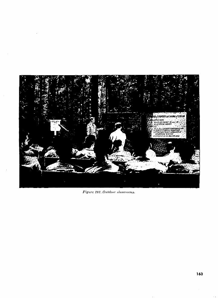
,/PKOPflmWCHAKfc/STATIOfl.. .-EDMEN -.• , ...Jrfi ltxttMOFtmiK'XiiKit'33 vft S•
Figure 262. .Outdoor classrooms.
163
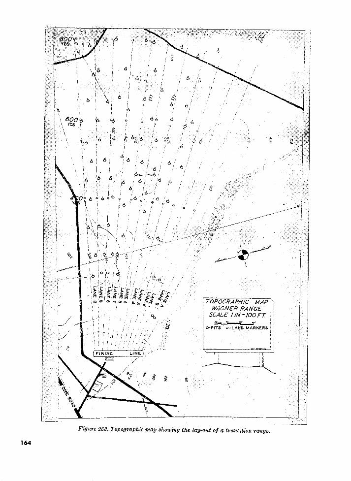
TOPOGRAPHIC MAP h WAGNER RANGE
SCALE UN,-1OOFT.
O-PITS o-LANE MARKERS
Figure 263. Topographic map showing the lay-out of a transition range.
164
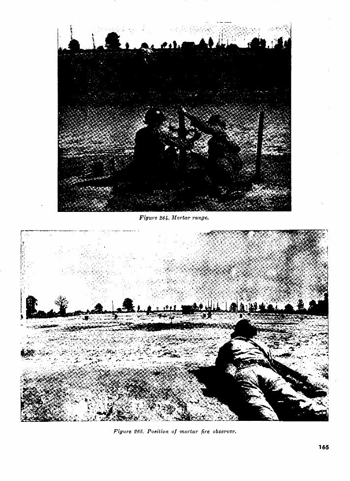
Figure 264. Mortar range.
Figure 265. Position of mortar fire observer.
165

1. Lyster bag—36 gal.2. Water can—5 gal.3. Water point—two 3,000-gal. tanks with sand and diatomaceous
filters and pumping unit4. Water purification—-canteen, water purification tablets, chlorine,
calcium hypochlorite ampule, and orthotolidine testing kit with tablets
5. Trailer, water tank—250 gal-6. Truck, 2^2-ton, water tank—700 gal.7. Helmet rack, wash stand8. Hand-washing devices9. Improvised field shower
10. Food storage (suspended containers)
11. Food storage (raised container)12. Mess kit washing unit, "vapos (Carlise) type"13. Mess kit washing unit, "immersion heaters"14. Mess kit washing uivt. "fire trench with three containers"15. Barrel (baffle principle) and soakage pit16. Garbage pit17. Incinerator-—oil drum type on cross trench18. Waste disposal'—cat hole19. Latrine—straddle trench type20. Latrine—deep pit type21. Latrine—bucket type22. Urinal—pipe and funnel type with soakage pit
Figure 266. Display of field sanitary facilities. (Arrows indicate general terrain slope.)
166

INDEX
Figure Page Accessories:
Sand table ________________________________________________ 151 100 Sled target ____________________________________________ 196 127 Terrain board, tank gunnery ________________,____________________ 158 104
Additions to manual. (See par. 6.)Aerial photograph recognition factors ___-__--_________---_____________________ 168 111Aggressor Army equipment :
Antiaircraft sound and flash simulator _________•___________________ 205 131Artillery flash and sound simulator ____________________________ 210-214 133,134Commander's kit ___________________________________________________ 121 70Control panel ________________________________________.._ 208,209 133 Documents ___________________________________________ 121 70Pneumatic 90-mm antiaircraft gun _____________________________ 204 131Tank, pneumatic, M24 _________________________________________ 206,207 132
Aiming circle, piece and panoramic sight ____--_-_______-_-_-----___-__________ 107 62Aiming point, auxiliary, machine gun _________________-______-_______-__--___ 112 65Air-ground communication panels _____________________________..____ 172,173 113Air observation panel _________________________________________ 169 111Air view, Ml rifle range ________________________________________ 251 157Aircraft, cargo, mock-up _________________________________________ 252-259 158-161 Ammunition box ____________________________________________ 221,222 138Angle of site micrometer _______________________________________________ 25 23Angle of site scale _____________________________________________________ 25 23Antiaircraft machine gun, M9, schematic diagram _________________________________ 115 66Antiaircraft machine gun trainer __________________________________________ 114 66Arena, seating ____________________________________________ 260,261 161,162Army Map Service. (See par. 9.)Artificial transmission line ____________________________________________ 175 115Artillery puff board. (See Puff board.)Artillery trainer _______________________________________________ 106 61Assault course, hand grenade —___________________________________ 246, 247 154,155Assembly, pointer guide __________________________________________________ 161 105Audio visual aids. (See chapter 2.)Automatic rifle. (See BAR.)Automotive display board, electrical system _______________________________________ 83 47Automotive display board, fuel system ________________________________________—_ 82 47Auxiliary aiming point, machine gun __________________________________________ 112 65Azimuth indicator model ________--__-----_____-_-_-___----________-_____-__ 183 121
Backstop, caliber, .22 range _______________________________________ 235 147Bailey type bridge __ ——————— __———————______________________ —— _ 95-97 55-56BAR, functioning frame, working drawing ——____________ —— __ —— _____________ 17,18 19,20BAR, plastic _ — ____—————————__ —— -----______-______________——- 38 29Bar, sighting ————————————————————————————————————————————————— 180,181 118,119BAR, weapons display ———————————————————___ ————— ——————————————— 88 50Barrel extension, machine gun ————————————:——————————___ — _ — __——— 55 35Barrel, machine gun ——————————————_ —— _____ ————— ———— ———————— _—— 58,59 36Bib, designation ——————————————————————————————————————————————— 231,232 143 Blackboard:
Commands and sensings ——————————_ — _______..__ — _____ —— —————— 157 104Computer's record ———————__——— —— -_-_-_______ —— _____ ——— _——————— 107 62General —————————————————————— ————— ———— ———————————————— 107 62Grid Sheets —————————————————————————————————————————————— 107 62Plain ——————————————————————- —————— -,——————— — — —————— 107 62Portable ——————————————————————————-—————————————————————— 226 140Recorder's sheet ————————____ ————— _-________---____-_----_____ — _— 107 62
167

Figure Page
Bolt, machine gun _________________———————————————————————— 45,54 32,35Booby traps and mines display _--—______—_________—__—__————--———— 91 52Boresighting, sight trainer, and target card (transparent paddle) ————————————— 187 122 Box:
Ammunition ___________-______———————————————————————— 22-1,222 138Packing _______________________---———————————————————— 107 62Rifle rest _____________-______———————————————————————— 222 - 138
Boyd stand ______________________————-———_—_—_——_—_—— 203 130Breech lock ______________-______———————————————————————— 56 36Breech lock and cam ____—______________________________——--—________———_ 57 36Bridge:
Floating, M4 ___________-_______————————————————————————— 99 57Floating, M4A2 ___________.________________________________ 98 57Panel, M2, Bailey type ________________.__________________—_ 95-97 55,56Raft section _______________________________—_-___ — ________ 100 58Timber trestle ________ —— _____-__—————————————————————————— 101 58
Calibration court, finger ________________-_---_--________________________— 240 151Cam, breech lock, machine gun __--________-__-__--_—__—_——-_———_—_——— 57 36Camouflage garnish patterns ____________________——______—__—______________ 94 54Carbine, weapons display _________________—__——________——______—______ 89 50Card:
Conventional signs and symbols __________ —— ———— ———————— —— —————— 11 14Pocket reference, chemical warfare ____-___-_--_____ — ________ — ____ — ____ — — 12 15Pull-off type ___________________________________________ 8 13Slot type ______________________________________________ 7 13Window shade type ______________________________________________ 9 13
Cargo, aircraft mock-up _________________ — ___ — ____—____ —— ___________ 252-259 158-161Cartoon _________________________________________________ 6 12Chages to manual. (See par. 6.) 8 Chart:
First aid _____________________________________________ 13 16Forceful message _______________________________________ —— _—____—_——_ 4 12General. (See par. 5 and 9.)Hinged type ___________________________________________ 10 13Local preparation. (See par. 10.)Lubrication order _______________j._______________________—— 1 9Photographic mural _____________________________________ 15 17Plain language ___________________________________________________ 5 52Topographical terms ___________________________________________________ 154 102
Chemical agent detector kit _________________________________ - -___ 118,119 67,68Chemical warfare pocket reference card _____.....——————————— ———— ______——— 12 15Circle:
Aiming, piece and panoramic sight ..._______________________________———— 107 62Rifle ____________________________________________________ 237 149
Classrooms, outdoors _____________________________________________ 262 163Clutch and flywheel mechanism _____________________________________ 80 46Cocking lever, machine gun _________________________________________ 47 33Combat formation display board _______________________________________ 166 109Communication panel board _____________________________________ 93 54Communications panel, air-ground ________________________________ 172,173 113Compass, cardboard replica ________________________________________________ 179 118Compass, model (oversize) ___-_______________--_--_-__________________ 68-70 40,41Computer's record ____________________________________ 107 62Conventional signs and symbols, card ___________________________________ 11 14Coordinate scales and protractors map reading ___________________________ 2 10Court, machine gun calibration ________________________________________ 241 151Crankshaft model ____________________________________________ 21 21
Deflection scale, radii of are __________________________________ 142 91Definition of training aids. (See par. 3.)Designation bib _______________________________________________ 231,232 143
168

Figure PageDial:
Machine gun __________________________ ___________________ 109 6324-hour clock ______________________________________________ 184 121Watch and sun __________________________________________ 177 116
Differential, final drive assembly _______________________________ 85 48Disassembly board, machine gun __ ._______________________________ 88 50Disassembly mats ____________________________________________ 14 17Display:
Board, combat formation ______________________________________ 166 109Rack, multiple _____________________________________________ 227 140
Displays and exhibits ___________________________________________ 71-94 42-54Distributor, cam mock-up _____________________________________________ 22 21Distributor, plastic ____________________________________________ 23 22Documents, Aggressor Army ______1______________________________ 121 70Driver's depth perception test, schematic diagram _ — ________________________ 110,111 64
Easel, graphic training aids, folding portfolio _—————_——______________________ 219 137Easel, slide rule ____________________________________________ 107 62Electrical system, automotive display board __———_—_____________:________ 83 47Electrical system panel, communication _______________________.____________ 93 54Electrical testing board _________________________________________ 178 117Elevation and windgage sighting device ____________________________________ 191 124Engine:
Functioning parts __________________-__________________________ 73 43GMC, internal combustion _____________—————-_————————————————-_ 73 43Radial, exploded _________________-__-__-_-_—_______________ 86 48
Extension, barrel _____________________________________________ 55 35
Fan, terrain _____________________________________________ 164 107Field artillery training kit, M36 ____________________________________ 107 62Field sanitary facilities ________-__-__—————————————————-——_____ 266 166Film Library, Signal Corps. (See par. 7.)Film strip, projector with slide adapter ———————————————————————————__ 201 129Films. (See par. 7.)Final drive and differential ————_——————————— —— ———————————————— 85 48Finger calibration court _____________—__—_____—____—_________—————— 240 151Firing lock, M15 ____________________————————__________________ 26,27 23Firing mechanism model, machine gun ___—___________—_——_—_____________ 42,43 31Firing pin, machine gun —————————————————————————————————————— 43-46 31,32Firing table, artillery ——_ —— _——————————————————————————————————— 107 62First aid training model, skeleton chart ————————————————————— ————— — 3,13 11,16 Flame thrower:
Plastic, M3 ______________________———————————_————-----__- 37 29Portable M2-2 gun group __________———————————————————____„_ 32 25Pressure regulator ——————————————————————————————————————- 31,33-36 25,26
Floating bridge ——————————————————————————————————————————————— 98,99 57Flywheel and clutch mechanism _____—________-_--—____—_—___—_______—_—— 80 46Frame, moving target, range —————————————————————————————————————— 194 127Fuel system, automotive —————————————————————————————————————— 82 47Functioning frame BAR —————————————————-—————————————————————— 17,18 19,20Fuselage, specifications for C-82 mock-up ——————————————— ——————————— — 253 158
Gas' identification set ———————————————————————————————————————— 116,117 67Gears:
Planetary ———————————————————————————————————————————— 19 20Transmission ——————————— ——————————————————————— —— ———— 81 46
Gin pole rigging ——————————————————————————————————————————— 143 92Graphic training aids ———————————————————————————————————————— 1-15 9-17Grenade launcher diagram ———————————————————————————————————— 40 30Gun group, flame thrower ————————————————————————————————————————— 32 25Gunner's quadrant, Ml —————————————————————————————————————————— 24 22Gunnery training kit, M36 —————_—————————————————————————————— 107 62
169

Figure PageHand grenade assault course:Lay-out and sketch __________________________________________ 246,247 154,155
Hardware, display __________________________________________ 87 49Hasty terrain model ________________________________________ 155 103Headspace, machine gun __________________________________________________ 51 34Hinged type chart ___________________________________________________ 10 13Holder, score book _________________________________________ 223 139Identification set, gas ________________________________________ 116,117 67Incinerator ______________________________________________________ 266 166Indicator:
Model azimuth _____________________________________________ 183 121Sandpaper-backed, movable _——________________________________ 167 110
Jeep, %-ton, cutaway _________________________________________ 77-79 44
Kit:Aggressor commander's _____-_-.__-_-__-_-__-_.._______-__-________________ 121 70Carrying ———_————_——————————___________—___________ 113 65Chemical agent detector, M9A1 ___-__________________________ 118,119 67,68Field artillery training, M36 ___________________________________ 107 62Map reading _______________________________________________ 120 69Photo interpreter, F2 ________________________________________ 105 60
Kits and trainers ______________________________ —— ________________ 95-142 55Knots and hitches display board .———————— — —— — _________ —— ______————— 76 44Laminated contour terrain model ______________________________________________ 152, 153 101Landscape target panels _________________________ ————— ______________ 248,249 156Lantern slide _____________-________,____________________ 192 125Launcher, grenade model _______________-__-______________--_-_-__----_— _____ 41 31Line, artificial transmission ___________________________________________________ 175 .115Lock, M15 firing ___________________________________________ 26,27 23Lubrication order chart _—_____________________________________ — ____ — ________ 1 9
Machine gun:Auxiliary aiming point _„ — _______________________________________ — _ —— __ 112 65Barrel construction ———_—______________________________ — _________________ 58,59 36Barrel extension — —— ___ — _ — _______ —— ________________________ — _______ 55 35Bolt ________________________________________________ 45,54 32,35Breech lock ____________________________________________ 56 36Caliber .50 sectionalized __________ ____________________________ 39 30Calibration court __________________________ ————— ________ ——.. 241 151Cam and breech lock ________________-________-______-__----_-_-_- — _ — _ — - 57 36Cocking lever ________________________________________— 47 33Dial _____________________________________________________ 109 63Disassembly board ———_______________________________________________ — ___ 88 50Firing mechanism model __________________________„___________________— ___ 42 31Firing pin ___________________________________________ 43,46,47 31,32,33Headspace _____________________________________________________________ 51 34Plastic __________________________________________________ 28-30,66 24,39Punchboard, portable ______„________________________________ 102-104 59Recoiling parts ______________________________________ — __________________ 53 35Sear spring ___________________________.._______________ —— - 48,49 33Sight setting __________________________________________.__ 62,63 37,38Square __________________________________________________ 238,239 150Trigger action ______________-______________________ .__.___ 44,50 32,33
Map reading:Coordinate scales and protractors _________—___________-_---__—____—__—— 2 10Kit _________________________________________________ 120 69
Maps:General. (See par. 5.) Military. (See par. 9.)
March card, time and space ________—————————— — —— ___________—————— 170,171 112Marksmanship training and paddle ___————————————————————————————— 228,229 141
170

Figure Page
Mat, disassembly, rifle ________________________________________ 14 17Micrometer, angle of site ________________________________________ 25 23Micrometer model ________________________________________..__ 20 21Military slide rule and easel _______________________________________ 107 62Mines and booby traps display _____________________________________ 91 52Miniature range target __________________________________________ 148,149 95,97Miniatures ________1_________________________________________ 143-149 92Miscellaneous devices ________________________________________ 165-191 108Mock-up:
Aircraft C-82 _______———___________________________________ 252-259 158-161C-82 fuselage specification ___________________________________ 258 158Distributor cam ___________________________________________ 22 21Piston ________________________________________________ 21 21Planetary gears ___ —— —— ___________________________________ 19 20Plans ————————————————_——_______________________________ 254-259 159-161Ramp —————————————————————————————————________________ 259 161
Model compass (oversize) ______---_-__________--__________________________ 68-70 40-41Mortar, board, sighting and aiming _______________________________________ 92 53Mortar, range lay-out ———————_ ——— __ —— __ —— . ——— _________________ 264,265 165Moulage, wound ______________________________.________________________ 230 142Moving target:
Frame, range _______________________________________________________ 194 127Lay-out ———————————————————_ ——— __ —— _ ——— _________________ 243 152Sled ———————————————————___._—_________,___________ 195,196 127
Multiple display rack _______________________________________________ 227 140Mural, photographic, chart ______--____________-.-_________-_-_______----_______ 15 17
Observer, mortar fire, technique of fire ___--__-_ —— __ — ._______________ 264,265 165Opaque projector ________——__ —— _________________________^_________ 202 130Optical pointer _________________________________________________________ 197 128Outdoor classrooms __________________________________________ 262 163
Packing box, gunnery training kit ——_•__ —— ————————— —— ———————————————— __ 107 62Panel:
Air-ground communications _ —————— __ ———— —— —— ——— ___———— —— _____ 172,173 113Air observation _____ — ___________________________________________________ 169 111Communications ____-___-__-_-_-_-__--_-____---__---____--________.._______ 93 54Landscape target _ —— _ —————————— ——————————————————— _ ————— ___ 248,249 156Marksmanship _____ —— __ ——— __ —— __ —— . ——— __ — ______ ——— ___ 228,229 141Sliding display —————————————————————————————————————————— 234 145
Photo interpreter kit, F2 ————————————————————————————————————————— 105 • 60Photographic mural chart ___________ — ____________________________ — — __________ 15 17Pistol:
Caliber .45 _________—————————————————————————————————_—— 16 18Display ___--___ — ————— ———————————————————- —-—————————— 89 50Ray-o-light ——————————————————————————————————————————— 188 123Working model ———————————————————————— _—————————— 16 18
Piston mock-up ————___ —— - ——————— — __ —— ________________ ————— ———— 21 21Planetary gears ——————————————————————————————————————————————— 19 20Plastic:
BAR ——————————————————————————————————————————————— 38 29Distributor ————————————————_—————————————————————————————— 23 22Flame thrower M3 ——_———————————————————————————————————————— 37 29Machine gun ——————————————————————————————————————————————— 28-30,66 24,39Rifle Ml ______—————————————————————————————————————— 67 40
Plotting equipment, gunnery training kit —————————————————————————————— 107 62Pneumatic equipment, Aggressor Army ————————————————————————————— 204, 206, 207 131,132Pointer:
Guide, specifications ————————————————————————————————————————— 159,161 104,105Optical —————————————————————————————————————————————— ' 197 128
Polaris ____————————————————————————————————————————————————— 176 116Portable rope rack —————————————————————————————————————————— 215,216 135
171

Figure Page Portfolio, graphic. (See par. 9.)Posters. (See par. 9.)Power train, M24 tank __————_——————_— -'.————-_—_______________ 74,75 43Preliminary rifle instruction circle, bill of materials ——__———______________ 237 149Pressure regulator, flame thrower M2-2 ___.________________________ 31,33-36 25,26Production, graphic aids. (See par. 10.)Projector:
Film strip with slide adapter ——————————————_———___——____——— 201 129General _______———___——__—________________________ 197-202 128-130Opaque .——————————————————————————'_—————————————————————— 202 130Slide -____—————————————————— ————— ——_________———— 199 128Slide (improvised) —————_._—————————————__________________—— 186 122Standard 16-mm sound, with speaker ———————__._——_____________—— 200 129
Protractors, map reading ———————_—_————_____________________ 2 10Public address system —————————————————————————————————————_————— 217,218 136 Publications, Department of the Army. (See par. 2.) Puff board:
Box _____———————————————————————_———___-______—— 124 73Construction ___________________________________________—— 126,127 75,76Dimensions of miniatures used with _____________________ —— _______ — ___ 134 83Elevation of frame _______________________________________ 133 82Floor plans and dimensions _____________________________________ 128,129, 131 77-79Hinge joint ____——_________________________________—— 136 85Joint and backboard ——________."___—____———___—————————— 130 79Plan of frame _____________________________________________ 132 81Plans for building carriage ———————————————————————————————————— 137 86Plans for the terrain ______———__________________ —— _____—— 135 84
' Range beam, pillow block, and carriage ___________________________ ——— _ 125 74Saddle and track ____________________________________________ 122 ' 71Screen frame and background _________________________________—— 123 73Size of terrain ________________________________________-___ T40 89Smoke ___________________________________________________ 122-142 71-91Terrain base ____________________________________________—— 138 87Trainer __________________________________________________ 139, 141 88,90
Pull-off type card ____——___________________________________—— 8 13Punchboard, machine gun, portable ——________________________————— 102-104 59
Quadrant, gunner's Ml ____________________________________..__—— 24 22
Rack, display, multiple _ ————— __ ———— ___ —— ____________________—— 227 140Rack, rope, portable _________________________________________—— 215,216 135Radial engine, exploded _ —— ________________—___________________________ — __ 86 48Radiation pattern ______________________________________________ 165 108Radii of arc and deflection scale ________________________________________ 142 91Raft, section, bridge ___—————__ ——— ___________________________——_ 100 58Ramp, mock-up _——————————————————————————___ —— ____________—— 259 161Range backstop, caliber .22 ——_____————_______________________________
Air view, Ml ____________-________________________________ 251 157Fire adjustment, tank gunnery _________________________________________ 242 151Mortar, lay-out ____________________________________________ 264,265 165Moving target, rifle grenade _____________________________________ 243 152Plans and specifications of transition ___________________________ 263 164Rifle _____________________________________________________ 149,236 97,148Rifle, 1,000-inch ____________________________________________ 250 157Transition _____________1__________________________________ 263 164
Range, backstop, caliber .22 _______________________________________ 235 147Range, target, frame, moving _____________________________________________ 194 127Ray-o-light:
Pistol ________________________________________________ 188 123Rifle ________________________________________________ 189 123
Rear projection method, daylight films _______________________________________ 224 139Recognition factors, aerial photograph ____________________________-___ 168 111Recoiling parts, model _—______________________________________ 52,53 34,35
172

T. , Figure Page Recorder:
Reproducer _______________________________________________ 233 144 Sheet —————————————____________._,________________ 107 62
Recordings. (See par. 8.)Records, USAFI. (See par. 8.)Regulator, pressure, portable flame thrower M2-2 _______________________ 31, 33-36 25-28Rifle:
Circle, preliminary rifle instruction and bill of material ________________ 237 149 Disassembly mat. _________. ___________..__________________ 14 17Plastic Ml _____________ ._________________________________ 67 40 Range, detailed lay-out ________..__.._________________________ 236 148 Range (miniature) ____________.. .____________________________ 148,149 95,97 Range, 1,000-inch ______________._________________________ 250 157 Ray-o-light __________________ ___. ___________________ 189 123 Sighting device ________________________________________ 190,191 124Weapons display ________________________..______________ 89 50
Rigging —————__————__________________________________________ 143,144 92Rocket, grenade, and launcher _______________-_.._____________ 89 50Roll target ______________________ ________ _______________ 174 114Rope rack, portable, diagram __________._..______________________ 215,216 135
Salvage. (See par. 12.)Sand table accessories _______________ .______________________ 151 100 Sand table construction ________________ _____________________ 150 99 Sandpaper-backed indicator ________________________________________ 167 110Sanitation, field equipment _________________________________________ 146,147,266 94,95,166Scale, angle of sight _—_______________. ___________________ 25 23Score book holder _________________ _______..___________________ 223 139 Screen, wall ______________________________________________ 198 128 Sear spring machine gun ——__________—————__________________________—— 48 33Seating arena __________________________..__________________________ 260,261 161,162Shadowgraphs:
Tin can spotlight ____________- ______________________________ 185 121 Sighting and aiming board, mortar ____-__-__-______________________________ 92 53Sighting bar ____________..________________________________ 180,181 118,119Sighting bar, adjustable front and rear sights _ ————— ————————— __ ——— __— 64 38 Sighting device:
Elevation and windgage ——————___- ——— __________ —————————_———— 191 124Showing bull's-eye ___,______________________________________ 190 124
Sighting disk, submachine gun ——————————————___ — __—————————————— 193 126 Sight picture model ———————————————————————————————————————— 220 138Sight setting, machine gur _________————————————————————————————— 62,63 37,38Sight trainer ______ .___________————————————————————————————— 187 122Silk screen process. (See par. 10.)Simulators, Aggressor Army equipment ——— —————————— ——————— ————————— 204-214 131-134Site table ______————————————————————————————————————————— 107 62 Skeleton first aid training model ——————————_ — — ___ ————— —————————— 3 11 Sled, moving target ——————————————————————————-—————————————— 195,196 127 Slide, adapter, film strip ———————————————_————————————————————————— 201 129 Slide, lantern ___———— —————————————-——————————————————— 192 125Slide projector ___———————————————————————————————————————————— 186,199 122,128 Slide rule and easel —————————————————————————————————————————— 107 62 Sliding display panel ———————————————————————————————————————— 234 145 Slidograph, portable ————————————————————————————————————————— 225 140 Slot type card __'_——————————————————————————————————————-——— 7 13 Smoke puff terrain board. (See Puff board.)Sniperscope ————————————————————————— ———— ———————————————— 72 43 Sniperscope display model ————————————————————————————————————— 71 42 Special Regulations:
310-20-series. (See par. 2.) 355-310-1. (See par. 2.)
Spotlight, "tin can" ——————————————————————————————————————— 185 121
173

Figure Page
Square, machine gun ___ —— _____ — —— _—______ — _________________________ 238,239 150Stand, Boyd ———————————————————————————————————————————_— 203 130Steering gear, cam and lever ___________________________________________ 84 48Submachine gun M3 —————————————————————_————______________ 89 50Submachine gun rest and sighting disk ———__————_—____.__________ 193 125
Table, firing, artillery, graphic _—________________________________ 107 62Table, sand ———————————————————————— —— __ ————— __——_________—— 150 99 Tank, communication trainer —————__ —— ___ —— ______________________ 108 63Tank, gunnery range, subcaliber ——_________-_-_-__-______________________ 242 151Tank, M24, live power train ———————_ — ___ —— _______________________ 74,75 43Tank, pneumatic, M24 __________________________________________ 206,207 132Target:
Backstop, .22 cal. ammunition ———————__ ————— ._ ———— _ —— ___——__—— 235 147 Close-up view of machine gun square ____________________________________ 239 150Landscape ————————————————_——__ ———— ——————— ———— __ — ___—— 249 156 Landscape, panel _——_—_______________ — ________________________ 248 156Lay-out, moving, antitank rifle grenade ——————————__ ————— ____ ——— _____ 243 152Manner of towing _———_——__________________________________________ 196 127Miniature range ———————————————————— ———— ——— ————— _ —— ___—— 148 95Practice shot group, ammunition box _______----___---_____-____________ 221 138Roll ———_————————————— — __——_ —— _ ———— — —— ___ —_______ ———— .__ 174 114Scoring, panel _____________________________________________ 228,229 141 Sled ___—___—_______———__——————————_——_———_— 195 127
Terrain board, smoke puff. (See Puff board.) Terrain board, tank gunnery —————__——__ ———— __ —— ___.____.____—— 156,158,160, 103,104,105,
162 106Terrain fan __________________________________________________ 164 107 Terrain model:
Hasty _________________________________________________—— 155 103 Laminated contours ____________-_____;.__— _______________ — ____________ 152,153 101
Terrain models, general. (See par. 27.)Test, driver's depth perception _ —— —— — __ — __ — ____ — _________________ — ___ — __ 110 64Testing board, electrical _______________————————————:————————— 178 117 Three-dimensional aids. (See par. 11.)Timber trestle, bridge _________________———_——_—____—___— 101 58 Time and space march cards ______________________—________________—_____ 170,171 112"Tin can" spotlight ________________________-________________ 185 121 Tire troubles panel ___________________—__—___—___—___— 90 51 Topographical terms chart ————————————————————— —— ____ —— ——————— 154 102Trainer:
Antiaircraft machine gun, M9 ______—————————— ___ — — ___——————————— 114,115 66Artillery, M3 ______________________________________________ 106 61 Sight ______________________________________________— 187 122 Tank communications ________________________________________—_____ 108 63
Training:Aid, "441" sight setting ______________——__ —— ________________ 60,61 37Aids, definition. (See par. 3.)Aids, use. (See par. 5.)Aids, value. (See par. 4.)Devices, miscellaneous ___—___——__——— ——— ______———————__—— 165-191 108-124Equipment. (See par. 3.) ______________ — ______ — _________ — ___ — ___ — __Facilities, general. (See par. 33.)Gunnery, tank __________________________________________ 156-164 103-107Kit, field artillery, M36 ___________________________________ 107 62Model, first aid, skeleton _______—___ ————— ——— __ ————— —— ——— 3 11
Transition range plans ___________________--_--____—________________ 263 164Transmission, gears, CMC, cutaway ___——__———— — —— —————————————— 81 46Transmission line, artificial ___________________---_-___-_--____--_____— _____ 175 115Trigger action, machine gun _____________-_-__-_-______-___________ 44, 50 32, 33Truck, %-ton cutaway __________________ ——— _ —— ________________ 77-79 44-45
174

USAFI records. (See par. 8.)
Vehicle course:Backing stallPrecision driving _ _ __ _ _ _ __ _ _ _
Vernier boardVernier plotting board ______Visual aids, audio. (See chapter 2.)
Wall screenWarehouse model _ _ ___ ____ _ _ _ ______Watch and sun dial model Weapons display:
BAR, caliber .30Carbine, caliber .30Machine gun __________ _ _Pistol, caliber .45Rifle, Ml, caliber .30Rocket and launcher, grenade _________Submachine gun, caliber .45 _______
Weatherproofing training aids. (See par. 9.) Windage correction device ____ _ __ ___ _ __Window shade type card _______ _ Working models Wounds, moulage
Figure
245244107
65
198145177
89898889898989
182 9
16-70 230
Page
153153
62394
12893
116
50505050505050
1201318
142
U. S. GOVERNMENT PRINTING OFFICE: 195O —— 9O2396
175