military technologies of the world
TRANSCRIPT


MILITARYTECHNOLOGIES
of the WORLD

Praeger Security International Advisory Board
Board Co-chairs
Loch K. Johnson, Regents Professor of Public and International Affairs, School of Publicand International Affairs, University of Georgia (U.S.A.)
Paul Wilkinson, Professor of International Relations and Chairman of the AdvisoryBoard, Centre for the Study of Terrorism and Political Violence, University ofSt. Andrews (U.K.)
Members
Anthony H. Cordesman, Arleigh A. Burke Chair in Strategy, Center for Strategic andInternational Studies (U.S.A.)
Thérèse Delpech, Director of Strategic Affairs, Atomic Energy Commission, and SeniorResearch Fellow, CERI (Fondation Nationale des Sciences Politiques), Paris (France)
Sir Michael Howard, former Chichele Professor of the History of War and RegisProfessor of Modern History, Oxford University (U.K.), and Robert A. Lovett Professorof Military and Naval History, Yale University (U.S.A.)
Lieutenant General Claudia J. Kennedy, US Army (Ret.), former Deputy Chief of Stafffor Intelligence, Department of the Army (U.S.A.)
Paul M. Kennedy, J. Richardson Dilworth Professor of History and Director,International Security Studies, Yale University (U.S.A.)
Robert J. O’Neill, former Chichele Professor of the History of War, All Souls College,Oxford University (Australia)
Shibley Telhami, Anwar Sadat Chair for Peace and Development, Department ofGovernment and Politics, University of Maryland (U.S.A.)
Fareed Zakaria, Editor, Newsweek International (U.S.A.)

MILITARYTECHNOLOGIES
of the WORLD
VOLUME
1
Praeger Security InternationalWestport, Connecticut • London
T.-W. LEE

Library of Congress Cataloging-in-Publication Data
Lee, T.-W. (Tae-Woo)Military technologies of the world / T.-W. Lee.
p. cm.Includes bibliographical references and index.ISBN 978-0-275-99535-5 (set : alk. paper) — ISBN 978-0-275-99537-9 (vol. 1 : alk. paper) —
ISBN 978-0-275-99539-3 (vol. 2 : alk. paper)1. Military art and science—Technological innovations—History. 2. Weapons systems—
History. 3. Military history. I. Title.U39.L42 2009623—dc22 2008034976
British Library Cataloguing in Publication Data is available.
Copyright © 2009 by T.-W. Lee
All rights reserved. No portion of this book may bereproduced, by any process or technique, without theexpress written consent of the publisher.
Library of Congress Catalog Card Number: 2008034976ISBN: 978-0-275-99535-5 (set)
978-0-275-99537-9 (vol 1)978-0-275-99539-3 (vol 2)
First published in 2009
Praeger Security International, 88 Post Road West, Westport, CT 06881An imprint of Greenwood Publishing Group, Inc.www.praeger.com
Printed in the United States of America
The paper used in this book complies with thePermanent Paper Standard issued by the NationalInformation Standards Organization (Z39.48-1984).
10 9 8 7 6 5 4 3 2 1

VOLUME 1
1. Air Superiority 1
2. Missile Technology 63
3. Helicopter Force 107
4. Stealth, Intelligence, and Surveillance Technology 139
5. Space Warfare: Nuclear Armaments and Missile Defense 189
VOLUME 2
6. Of Guns and Cannons 221
7. Fortress on Wheels: Main Battle Tanks 253
8. Modern Armada 287
9. Submarines 319
10. Perspectives on Military Technology 363
Index 371
Contents

This page intentionally left blank

AIR SUPERIORITY
CHAPTER
1
TECHNOLOGY CHANGES the way battles are fought. The rarity of notable air battlesinvolving dogfi ghts in the post–Vietnam War era can be attributed to the advances in air-to-air missile technology where longer range and better lock-in guidance have continu-ously increased the engagement distance between aircrafts. The U.S. Air Force, forexample, has not had an ace (fi ve aerial kills or more) since 1972. In many instances, thebattle is already decided on the radar long before visual contact is made. In recent confl ictsin the Middle East, air superiority was quickly established by the United States and alliedair forces, and the opposing fi ghters were mostly destroyed on the ground after their radarand communication installations were knocked out in preemptive, stealth strikes or theysimply elected not to engage the U.S. fi ghters. The advances in technology, at least inaerial battles, quickly made the prior-generation aircraft and armaments obsolete and re-sulted in lopsided advantages for the side in possession of the superior technology. TheIsrael-Syria confl ict back in 1982 and U.S.-Iraqi confl icts from 1991 onward have shownthat Russian-built MiG-29s and their equivalents were not of much threat to the F-15,F-16, and other western counterparts. While it is true that a large part of the western su-periority also lies in the preparedness and training of the pilots, the training itself requiresmany technological advances in fl ight simulators and battle scene reconstruction usingcomputers. More advanced Russian Sukhoi Su-30s and MiG-35s, on the other hand, areviable weapons with potent sets of armaments and are making their way into the air forcesoutside of Russia. The United States has in the meantime produced probably the mostadvanced aircraft in history in the F-22 Raptor that embodies state-of-the-art technologiesin stealth, armaments, and battlefi eld management electronics. The more compact andutility-oriented (less expensive) F-35 “Joint Strike Fighter” is also in the works.
To fi nd an example of aerial combats involving U.S. aircraft, one needs to look as farback as 1989 in the Mediterranean region off the coast of northern Libya, a country inNorth Africa next to Egypt. At the time, the Libyan strongman Muammar al-Qadhafi leda rogue state of anti-American dictatorship. Using oil money, he had equipped his air forcewith Russian-made jets including the MiG-23 Flogger. With the advent of long-range anti-ship missiles and sophisticated air strike jet fi ghters, the U.S. aircraft carrier John F. Ken-nedy operating in the area was on high alert. The tensions that existed between Libya andthe United States in preceding years, along with the unpredictable nature of Qadhafi , fueledthe prospect of an armed encounter in this region. A naval battle group, while carrying atremendous range and punch through its carrier-launched fi ghters (F-14 Tomcats), also isvulnerable to missile and air attacks. For this reason, a battle group always moves with anairborne early warning capability, in this case in the form of E-2C Hawkeye surveillanceaircraft. The long-range radar coverage of the E-2C allowed the intercept controller aboard

2 Military Technologies of the World
to detect two Libyan aircraft taking off from the Al-Bumbah air base more than 100 milesdeep in Libya and approaching the two F-14 Tomcats then on patrol in the air space abovethe Gulf of Sidra off the Libyan coast. One of the patrol mission objectives was to protectthe air space near and above the carrier, and the F-14s took an air path to intercept thebogeys from a rear, threat position. Instead of holding their course, the Libyan MiGs madea counter move to circumvent the F-14s. Apparently the Libyan ground-based radars wereclosely monitoring the situation, and instructions were being sent to maneuver against theTomcats. This cat-and-mouse jockeying of position repeated, with each side attempting togain an advantage by taking a pursuit position from the rear. From this pursuit position, theforward-looking radars and also the heat-seekers can lock on to the opposing aircrafts with-out the possibility of that favor being returned. At twenty miles and closing fast from ahead-on position, it became evident that the Libyan MiGs had no intention of being es-corted out of this air space and every intent of engaging the F-14s. It is unclear whether theLibyan MiGs were locking on to the F-14 Tomcats, but the WSO (the weapons system of-fi cer, also referred to as radar intercept offi cer, RIO, at this time) onboard one of the F-14swas advising the lead pilot to move the aircraft in position for an optimum launch. At thisdistance and speed, the two opposing sides are fair games for the air-to-air missiles andunder intense pressure of oncoming MiGs, one of the F-14s fi red two Sparrow missiles thatdid not come close to the target. In the heat of battle, the WSO had the radar in a track-and-scan mode, which did not provide radar illumination to guide the Sparrow missileswith passive radar guidance. The Sparrows pursue the target in response to the radar signalilluminated by the launch aircraft. All of this transpired without the two sides having vi-sual contact of the other. Now, the MiGs appeared as specks in the sky, and the Tomcatssplit up with the wingman heading directly into the MiGs while the lead Tomcat veered togain a rear position. The Tomcat approaching the MiGs this time successfully locked theradar onto one of the bogeys and fi red, resulting in a spectacular explosion. Incredibly, thepilot escaped in an ejection chute. The lead Tomcat fi nally gained the pursuit angle on theremaining MiG and fi red a short-range, heat-seeking Sidewinder that tracked the jet ex-haust heat and made contact. The entire sequence lasted approximately four minutes, andmost of the battle was fought in the radar space without visual contact. Not a single shot ofthe Vulcan cannon was fi red.
A new era in the use of the air force in highly coordinated, precision attacks was openedduring the Operation Desert Shield in 1991. Although only 5 percent of all the munitionsdelivered during this operation was of the guided type, it proved that optimal use of the airpower could debilitate the entire defense infrastructure of the opposing side, starting fromthe command and control down to the infantry level dug in foxholes. The lopsided supe-riority of the coalition aircraft and pilots were proven at the outset by the fact that thirty-nine of the outdated Iraqi MiGs were promptly shot down. In the next days, some of theremaining Iraqi aircraft sought refuge in Iran to become permanent properties of Iran, andthe brief phase of the air-to-air encounters ended without much drama. Although therewere some 800 Iraqi aircraft, few of them challenged the coalition air force. U.S. Navy andAir Force AWACS airplanes located and identifi ed Iraqi threats from the outset, in somecases alerting the nearby coalition aircraft to fi re their SAM missiles to destroy Iraqi air-crafts just as they cleared the runway during takeoff. In another instance, a Navy F/A-18pilot was alerted of an approaching Iraqi fi ghter and using a Sidewinder missile recorded abeyond-the-visual-range kill forty seconds after the AWACS alert. The overall result wasa complete control of the air space from which coordinated, multidimensional attacks onthe Iraqi targets could be made at will and with minimal losses, human or machine, to thecoalition side. During the second operation against Iraq ten years later, Operation Endur-ing Freedom, a similar approach was taken except with much increased size and performance
3Air Superiority
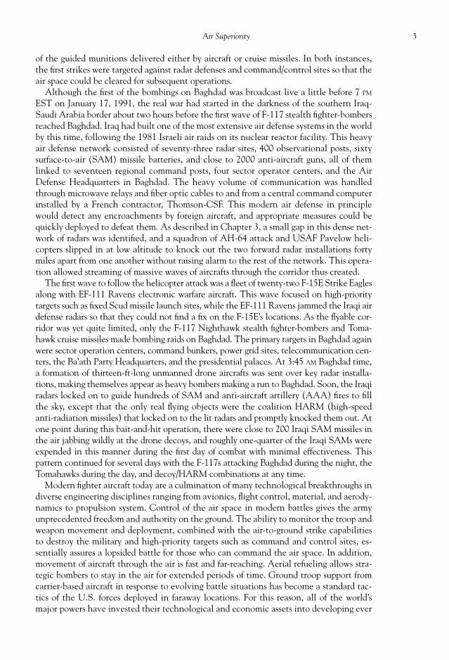
of the guided munitions delivered either by aircraft or cruise missiles. In both instances,the fi rst strikes were targeted against radar defenses and command/control sites so that theair space could be cleared for subsequent operations.
Although the fi rst of the bombings on Baghdad was broadcast live a little before 7 PM
EST on January 17, 1991, the real war had started in the darkness of the southern Iraq-Saudi Arabia border about two hours before the fi rst wave of F-117 stealth fi ghter-bombersreached Baghdad. Iraq had built one of the most extensive air defense systems in the worldby this time, following the 1981 Israeli air raids on its nuclear reactor facility. This heavyair defense network consisted of seventy-three radar sites, 400 observational posts, sixtysurface-to-air (SAM) missile batteries, and close to 2000 anti-aircraft guns, all of themlinked to seventeen regional command posts, four sector operator centers, and the AirDefense Headquarters in Baghdad. The heavy volume of communication was handledthrough microwave relays and fi ber optic cables to and from a central command computerinstalled by a French contractor, Thomson-CSF. This modern air defense in principlewould detect any encroachments by foreign aircraft, and appropriate measures could bequickly deployed to defeat them. As described in Chapter 3, a small gap in this dense net-work of radars was identifi ed, and a squadron of AH-64 attack and USAF Pavelow heli-copters slipped in at low altitude to knock out the two forward radar installations fortymiles apart from one another without raising alarm to the rest of the network. This opera-tion allowed streaming of massive waves of aircrafts through the corridor thus created.
The fi rst wave to follow the helicopter attack was a fl eet of twenty-two F-15E Strike Eaglesalong with EF-111 Ravens electronic warfare aircraft. This wave focused on high-prioritytargets such as fi xed Scud missile launch sites, while the EF-111 Ravens jammed the Iraqi airdefense radars so that they could not fi nd a fi x on the F-15E’s locations. As the fl yable cor-ridor was yet quite limited, only the F-117 Nighthawk stealth fi ghter-bombers and Toma-hawk cruise missiles made bombing raids on Baghdad. The primary targets in Baghdad againwere sector operation centers, command bunkers, power grid sites, telecommunication cen-ters, the Ba’ath Party Headquarters, and the presidential palaces. At 3:45 AM Baghdad time,a formation of thirteen-ft-long unmanned drone aircrafts was sent over key radar installa-tions, making themselves appear as heavy bombers making a run to Baghdad. Soon, the Iraqiradars locked on to guide hundreds of SAM and anti-aircraft artillery (AAA) fi res to fi llthe sky, except that the only real fl ying objects were the coalition HARM (high-speedanti-radiation missiles) that locked on to the lit radars and promptly knocked them out. Atone point during this bait-and-hit operation, there were close to 200 Iraqi SAM missiles inthe air jabbing wildly at the drone decoys, and roughly one-quarter of the Iraqi SAMs wereexpended in this manner during the fi rst day of combat with minimal effectiveness. Thispattern continued for several days with the F-117s attacking Baghdad during the night, theTomahawks during the day, and decoy/HARM combinations at any time.
Modern fi ghter aircraft today are a culmination of many technological breakthroughs indiverse engineering disciplines ranging from avionics, fl ight control, material, and aerody-namics to propulsion system. Control of the air space in modern battles gives the armyunprecedented freedom and authority on the ground. The ability to monitor the troop andweapon movement and deployment, combined with the air-to-ground strike capabilitiesto destroy the military and high-priority targets such as command and control sites, es-sentially assures a lopsided battle for those who can command the air space. In addition,movement of aircraft through the air is fast and far-reaching. Aerial refueling allows stra-tegic bombers to stay in the air for extended periods of time. Ground troop support fromcarrier-based aircraft in response to evolving battle situations has become a standard tac-tics of the U.S. forces deployed in faraway locations. For this reason, all of the world’smajor powers have invested their technological and economic assets into developing ever

4 Military Technologies of the World
more potent jet fi ghters and bombers. In this chapter, we examine the technological ad-vancements found in some of these aircrafts.
UNITED STATES AIRCRAFT
The F-15 Eagle fi ghter aircraft that once was the mainstay of the U.S. Air Force in main-taining air superiority is shown in Fig. 1.1. The F-15 Eagle has several versions from F-15Ato F-15E and represents the main all-weather tactical fi ghter for the U.S. Air Force and alsofor several ally nations (Israel, Japan, Saudi Arabia, and South Korea). Developed in re-sponse to the alarming improvements in Russian fi ghters such as the MiG-25 Foxbat, F-15Eagles lived well up to their expectations by continuously outperforming any contendingaircraft in various air battles. In fact, on record no F-15 fi ghter was lost in an aerial combat.Although two F-15Es were brought down by ground fi re in the Iraqi theater in 1991, its su-periority in aerial engagements is unprecedented as given by the accumulated statistics of104 kills against 0 losses in aerial battle. Since 1979, F-15s have been deployed in battlemainly by the Israeli and U.S. forces, and they continuously overwhelmed adversaries withsuperior electronic and maneuver capabilities, shooting down mostly Russian-made aircraftranging from MiG-21 “Fishbeds,” MiG-23 “Floggers,” MiG-25 “Foxbats,” and MiG-29 “Ful-crums,” to Su-25 “Frogfoots,” Su-22 “Fitters,” and French Mirage F1s fl own by the Iraqis.
Given the success of the F-15 and subsequent, more advanced fi ghters produced by theAmerican aerospace industry, it may come as a small surprise that the F-15 emerged as areplacement for the F-4 Phantom jets, which were clearly outclassed by the Russian jetfi ghters of the time. It is no coincidence that the size and even the exterior of the F-15aircraft resembles those of MiG-25 because it was the aim of the U.S. military to combatthe threats posed by the class of Russian jet fi ghters at the time. Further revelations of the
Figure 1.1. An F-15 Eagle. Photo courtesy of the U.S. Air Force.

5Air Superiority
actual performance, however, have proven that in spite of the Russian jets’ record-breakingspeed and rate-of-climb, their size and weight made these heavyweights vulnerable indogfi ghts due to lack of maneuverability. F-15s, however, made extensive use of titaniumin the airframe to lower their bulk weight. Adding to this formula was the then state-of-the-art power plant, Pratt and Whitney F-100-PW-100 turbofan engines. These engines pro-vided a 25,000 lb thrust with the afterburners running, which was eight times the engineweight. Also, the small wing area and advanced control systems allowed the F-15 thenunprecedented maneuverability in addition to its range and armament capacity.
The letter designation for F-15 follows its evolution from its introduction to the U.S.Air Force in 1976:
F-15A: The version introduced in 1976, single seat. F-15B: Two-seat trainer version of F-15A. F-15C: Improved version of F-15A. 2000 lb of additional internal fuel capacity, external
conformal fuel tanks, and improved power plant allowing for maximum takeoff weightof 68,000 lb.
F-15D: Two-seat trainer version of F-15C. F-15E: Two-seat, all-purpose version for deep strike and interdiction. Improved weap-
ons control and electronics.
Although, the F-15E Strike Eagle is based on the same airframe as the preceding F-15series, it is perceived as an aircraft in a different class both by its pilots and military ana-lysts. It has capabilities far exceeding its predecessors. To handle the advanced weaponscontrol systems, the F-15E allows for a weapon system offi cer (WSO) to sit behind thepilot. The added capabilities allow F-15Es to carry out long-range ground assault missionsunder any conditions. Table 1.1 gives some of the main characteristics of the F-15E StrikeEagle. F-15E armaments include air-to-air missiles like AIM-9, AIM-7, various guidedbombs such as CBU-10, -12, -15, and -25, and an air-to-ground missile, AGM-65. Someof the key electronic gears are the synthetic aperture radar, head-up display (HUD), andLANTIRN (Low Altitude Navigation and Targeting Infrared for Night).
Although the F-15’s prowess was well recognized, it was a large and expensive aircraft.Though many of the shortcomings of the F-4 Phantom were overcome using superiortechnology, the F-15 got big and costly to give heavy armament capabilities and fl ightperformance. Proponents within the U.S. Air Force for small, agile aircraft more suitable
Table 1.1. F-15E Specifi cations.
Length 63.8 ft (19.45 m)Wingspan 42.8 ft (13.05 m)Height 18.5 ft (5.64 m)Maximum Take-Off Weight 81,000 lb (36,818 kg)Power Plant 2 Pratt & Whitney F100-PW-229
afterburning turbofansTotal Thrust 58,200 lbMaximum Speed High altitude: Mach 2.5 or 1650 mph (2655 km/h)
Low altitude: Mach 1.2 or 900 mph (1450 km/h)Ceiling 65,000 ft (20,000 m)Range 3500 miles (5600 km)Rate of Climb 50,000 ft/min (255 m/s)Thrust-to-Weight ratio 1.30

6 Military Technologies of the World
for air combat got what they wished in the F-16 Fighting Falcon. Smaller and less expen-sive than the F-15, the F-16 would have unparalleled maneuverability at the time of itsintroduction, transient performance including acceleration and climb at all speed ranges,along with effective armaments for air combat. The Lightweight Fighter (LWF) programout of which the F-16 originated had objectives of developing a highly capable aircraft of20,000-lb weight (about half that of the F-15), low cost of production and operation, andhigh performance at Mach 1.6 and below and at altitudes of 40,000 feet and below. Thecost for the F-16A/B would turn out to be about $15 million per airplane, about half thecost of the F-15 and one-tenth that of the ultramodern F-22 described next. Yet, the F-16featured many of the technological advances, some beyond even those of the F-15. TheF-16 was intentionally designed to be aerodynamically unstable with the center of gravitywell behind the center of lift at the main wing. The natural tendency for the aircraft thenis to pitch up and go out of control. Thus, the aerodynamic surfaces like the horizontalstabilizers need to be constantly engaged to maintain the aircraft’s level motion. This sta-bilization is performed by onboard quadruple-redundant computers in what is known asfl y-by-wire. As opposed to direct hydraulic control of the aerodynamic surfaces by thepilot’s control stick, the computer receives the pilot input digitally (i.e., by wire) andcomputes the necessary confi gurations for the desired aircraft attitude and motion. Theconfi guration data are then transmitted again via wire to the hydraulics, which in turnrotate the aerodynamic surfaces. The fl y-by-wire has much quicker response, and becausethe aircraft is naturally unstable its ability to go into unusual fl ight angles is much greater(i.e., the aircraft becomes much more agile). The higher agility means that it can makehigh-G turns, which was limited to about 7 Gs in previous aircrafts. By reclining the pilotseat to thirty degrees instead of the usual thirteen degrees and placing the control stick tothe right side with an armrest, F-16 pilots could withstand and control up to 9-G turns.Also, the blended body design where the wing gradually merged with the aircraft bodyreduced the aerodynamic drag while increasing the available space for internal fuel stor-age. The increased fuel capacity and an effi cient turbofan engine (General Electric F110-GE-100) give the F-16 an exceptional range (2435 miles) for an aircraft of its size.
We can see the next plateau in the military aircraft technology in the recent additionto the U.S. Air Force fi ghter fl eet, the F-22 Raptor shown in Figs. 1.2 to 1.4. The F-22Raptor design originated from the need to replace the aging F-15 Eagles and provide theUSAF with a dominant super-fi ghter that will ensure air superiority for the next severaldecades. In spite of the F-15 Eagle’s modern look, they were introduced to service back
Figure 1.2. F-22 Raptor. Photo courtesy of the U.S. Air Force.

7Air Superiority
in 1976. Even with all the successes of the F-15 program,vast advances in military aircraft technology have takenplace. Many of these advances and several new ones areembedded in the F-22 Raptor, which entered service in2005. New materials such as advanced alloys and com-posite material are used in the Raptor airframe, aerody-namic surfaces, and engine components. The control isvastly improved for both routine and high-G maneuversusing fl y-by-wire system. The computerized control ofthe F-22, as opposed to direct pilot control, allows theaircraft to perform highly unstable maneuvers. For ex-ample, the F-22 can fl y at an angle of attack of sixty de-grees, well beyond the stall limit of the aircraft. Thepower plant gets an even higher effi ciency thrust, alongwith advanced thrust vectoring, using Pratt and Whit-ney pitch-vectoring turbofans. The electronic equip-ment is so far advanced that the F-22 can serve as anadvance airborne station for electronic warfare and bat-tlefi eld intelligence management. The complex radarand sensor inputs are synthesized and displayed to thepilot in integrated avionics displays to maximize thesituational awareness and decision abilities of the opera-tor. The sensitive suite of sensors is designed to alwaysgive the F-22 the fi rst-kill option long before the opposingaircraft or targets are even aware of the presence of thisstealth fi ghter. The airframe geometry, material, and theexhaust section have all been designed for reduced visualand electromagnetic observability, essential for surviv-ability and preemptive strike roles. Two Pratt and Whit-ney engines propel the F-22 to supersonic cruise speedsand give unmatched agility with vector thrust nozzles.
Figure 1.3. The underside of the F-22 Raptor. Most of the armament is carriedin the interior bay. Photo courtesy of the U.S. Air Force.
Figure 1.4. F-22 showing its vertical fl ight ca-pability. Photo courtesy of the U.S. Air Force.

8 Military Technologies of the World
All of the previously mentioned technological advances did not come without a highprice tag. Many of the new technologies were researched and developed as part of the F-22project. If all the development costs are added in, each F-22 carries a price tag of over $300million. In fact, the next-generation joint strike fi ghter (JSF), the F-35, is under develop-ment so that these advanced technologies can be furnished at lower cost and in largervolume. The high cost of the F-22 also makes some of the existing aircraft such as theF-15, F-16, and F-18 indispensable elements of the American airborne capabilities. Table1.2 shows some of the main specifi cations of the F-22.
The F-22 airframe can be divided into three major sub-frames that are manufactured bydifferent companies. The forward fuselage along with the fi ns (vertical and horizontalstabilizers), fl aps, ailerons, and leading-edge fl aps in the wings comprise one sub-framegroup that is made by Lockheed Martin in Marietta, GA. Lockheed Martin in Fort Worth,TX, constructs the complex mid-fuselage that measures 17 feet in length and 15 feet inwidth, prior to assembly with other sub-frames. This section houses the core of the hydrau-lics and electronic networks. The aft fuselage section is built by Boeing and includes themain wings, power supplies, auxiliary power units (APUs), and other sub-components.Much of the structural load on the aircraft is supported by the fi ve titanium bulkheads inthe mid-fuselage. The clipped delta wings are designed for effi ciency at high speeds andhave ailerons, fl aperons, and leading-edge fl aps to give an enlarged fl ight envelope. Theleading-edge fl aps, for example, maintain controlled fl ow over the wings at high angles ofattack over sixty degrees. The internal space of the wings, as in other aircraft, serves as fueltanks. The ailerons operate in opposite directions in both wings to provide roll force,while the fl aperon increases lift and controls the fl ow at high angles of attack. The hori-zontal stabilizers also shield the engine exhaust radiation, in addition to performing as apitch-control aerodynamic surface. The vertical stabilizers are angled in the same direc-tion as the sloped aft fuselage. The heavier armaments like the AIM-120 AMRAAMGBU-30 1000-lb bombs are kept in an internal weapon bay with retractable covers, andthe two AIM-9 Sidewinder missiles are also stored internally near the air intake. The in-ternal storage decreases both the aerodynamic drag and radar refl ection signatures. M61A220-mm-caliber Vulcan rotating cannon gives the continuous fi re capability of 480 rounds.The primary airframe, the mid-fuselage, is a unifi ed structure manufactured using an ad-vanced casting process. Using a high-pressure injection of molten titanium in an auto-clave, the complex mid-fuselage is constructed as a single structure with no welds or joints.
Table 1.2. F-22 Specifi cations.
Length 62.1 ft (18.9 m)Wingspan 44.5 ft (13.56 m)Height 16.8 ft (5.08 m)Maximum Take-Off Weight 80,000 lb (36,288 kg)Power Plant 2 Pratt & Whitney F119-PW-100
pitch-vectoring turbofans with afterburnersTotal Thrust 70,000 lbMaximum Speed High altitude: Mach 2.42 or 1600 mph (2570 km/h)
Low altitude: Mach 1.72 or 1140 mph (1826 km/h)Ceiling 65,000 ft (20,000 m)Range 2000 miles (5600 km)Rate of Climb N/A (classifi ed)Thrust-to-Weight Ratio 1.26Maximum G-load –3/+9.5
9Air Superiority
This method achieves high-strength integrity with reduced weight and machining time.Composite materials and specialized alloys are used for critical components to providestrength at low weight and radar signatures.
The stealth capability encompasses minimizing radar, visual, infrared, and audible sig-natures, with the radar being the most critical. The radar cross-section, or RCS, is a mea-sure of the aircraft’s visibility when illuminated by a radar beam and basically means theequivalent cross-sectional area of a surface if that surface were to refl ect all of the incidentradar energy. A large bird, for example, has an RCS of 0.01 m2 , much smaller than its ac-tual cross-sectional area because a bird’s feather does not refl ect radar energy effi ciently.The B-2 bomber, with somewhat earlier stealth technologies and larger dimensions, has aRCS of 0.75 m2 . The RCS of the F-22 is estimated to 0.01 m2 , about the same as a largebird and essentially invisible to the radar. First, all of the F-22 surfaces tend to form acuteangles, so that the incident radar does not bounce back to the source to reveal its presence.For example, the F-22 has a cross-sectional shape of a fl at triangle and straight-line fea-tures on the aircraft are replaced with W-shaped lines. Radar-absorbing paints and materi-als are used for all of the exposed surfaces. The rotating engine fans are a signifi cantcontributor to RCS, and in the F-22 the serpentine inlet duct does not allow the radarbeam to make contact with the engine fan. Even the radar refl ection from the pilot’s hel-met through the canopy has been taken into account. The glass canopy is plated with ra-dar-insulating thin fi lm while maintaining 85 percent transmission of the visible light.Thus, the entire canopy can be considered as a radar fi lter. The exhaust is the most criticalcomponent in minimizing infrared signatures that can be imaged by FLIR (forward-look-ing infrared) or IR sensors in heat-seeking missiles. The exhaust of the F-22 is designed toabsorb the heat by using ceramic components, rather than conduct heat to the outsidesurface. Also, the horizontal stabilizers are placed to shield the thermal emission as muchas possible. The camoufl age paint schemes blend the aircraft into the sky when viewedfrom below and into the ground when observed from the top. Vapor trails and other tell-tale contrails are aerodynamically suppressed.
The Pratt and Whitney F119-PW-100 engine is another component in the F-22 that isarguably the most advanced in aircraft technology. Each of these engines generates morethrust without the afterburner than conventional engines with full afterburner power on,and its supersonic thrust is also about twice the other engines in the class. Using two ofthese engines to develop a total thrust of 70,000 pounds, the F-22 can travel at supersonicspeeds without the afterburners for fuel-effi cient high-speed cruise to the target area. Thislevel of thrust is more than the aircraft weight and enables the F-22 to fl y vertically upwardmuch like a rocket. The F119 engine is also unique in fully integrating the vector thrustnozzle into the engine/airframe combination for a twenty-degree up/down redirection ofthrust for high-G turn capabilities. The thrust vectoring is designed to enhance the turnrates by up to 50 percent in comparison to using control surfaces alone. The engine achievesall these functional characteristics with 40 percent fewer parts than conventional enginesto furnish exceptional reliability and maintenance and repair access. In a design methodcalled integrated product development, inputs from assembly line workers and air force me-chanics were incorporated to streamline the entire sequence of engine production, mainte-nance, and repairs. These design innovations are expected to reduce the support equipment,labor, and spare parts in demand by approximately one-half. Similar to the mid-fuselageairframe, the turbine stage consisting of the disk and blades is constructed in a single, in-tegrated metal piece for high integrity at lower weight, better performance, and thermalinsulation for the turbine disk cavity. The fan and compressor blade designs went throughextensive permutations and modifi cations using computational fl uid dynamic (CFD) sim-ulations, resulting in unprecedented effi ciency in both sections. Hardware cut-and-try of

10 Military Technologies of the World
different designs would have cost way too much time and money. High-strength and deg-radation-resistant “Alloy C” was used in key components like the compressors, turbines,and nozzles to allow the engine to run at higher temperatures, one of the important con-tributing factors to the increased thrust and durability of F119 engines. The combustor,the hottest component in the engine, uses oxidation-resistant, thermally insulating cobaltcoatings. A digital electronic engine control device called FADEC (dual-redundant digi-tal engine controls) not only fi ne-tunes the engine operating parameters to deliver thehighest performance at the maximum effi ciency, but also establishes responsive and pre-cise engine operating parameters with inputs from the pilot control of the throttle and theengine/fl ight sensors.
The F-35 Lightening II Joint Strike Fighter (JSF) Program represents the effort to providea capable, multi-mission aircraft while containing the budget. The F-35’s price tag is abouthalf of the F-22 Raptor’s. The argument for wide adoption of this scaled-back aircraft is thatthe F-22’s capabilities are best directed against opponents with similar technological capa-bilities, and with the changed geopolitical environment in the United States, F-22 Raptorsare less likely to be involved in such encounters. On the other hand, emerging powers likeChina could in theory bring more capable aircraft into the picture, and by moving away fromthe F-22 production the United States may lose the capability to put a signifi cant number ofthe advanced F-22s on the scene. Though somewhat smaller than the F-22 and with a singleengine, the F-35 (Fig. 1.5) does contain many of the stealth technologies and has a weaponscapacity of 15,000 pounds. The JSF is designed to be used across the military branches, andin addition to the standard conventional take-off and landing version (CTOL) F-35A for airforce use, there will be an F-35B, the short-takeoff and vertical landing (STOVL), and anF-35C for carrier-based (CV) missions. The air force version F-35A is expected to replacethe F-16 and A-10 and to augment the F-22. The navy version F-35C will augment the F/A-18E/F and will have larger wing and tail surfaces for carrier take-off and landing. The F-35Cwill also overcome one shortcoming of the F/A-18 by being capable of twice the range oninternal fuel alone. The unique variants are in the marine STOVL version, F-35B, alsoplanned for adoption by the British Royal Navy to replace the Sea Harrier. The short take-off is facilitated by a number of auxiliary nozzles to divert the thrust. In a normal engine, the
Figure 1.5. F-35 Lightening II, the Joint Strike Fighter. Photo courtesy of the U.S. Air Force.

11Air Superiority
jet exhaust is pushed out the nozzle at the rear of the engine to provide only forward thrust.In engines with thrust reversers, the fan stream is redirected to the forward direction to gen-erate negative thrust. The same concept can be used to redirect the thrust to other directionsby using auxiliary nozzles. For the F-35B, there is a lift nozzle that takes the fan exhaust anddirects it vertically downward. Also, the pitch nozzle at the main nozzle can be turned to adda vertical component in the thrust. For control of the aircraft during this tricky maneuver,there are four additional nozzles. Nozzles control the roll angle by sending a small fraction ofthe main exhaust at off-horizontal angles, while two yaw nozzles generate thrust in the for-ward and backward off-set angles.
Reliability-driven components and manufacturing are intended to lower the mainte-nance costs, and advanced avionics and sensors (AN/APG-81 AESA radar) are embeddedin the aircraft. A large panoramic cockpit display (PCD) and direct voice input enhancethe pilot’s ability to multitask. The AN/APG-81 Fire Control Radar consists of an activeelectronically scanned array (AESA) and is an improvement over the original radar in-stalled on the F-22 (AN/APG-77). This sensor has both the air-to-air and air-to-groundscan/track capabilities at high resolutions and can acquire multiple targets while engagingin counter-electronic functions. Electro-optical sensors are embedded at various points onthe aircraft body to detect missile and other threats, and the inputs are integrated into theAN/AAS-37 infrared search and track system. This sensor network is referred to as EOTS(electro-optical targeting system) and provides a new level of situational awareness byusing multiple sensors to cover the entire spherical periphery of the aircraft and facilitatesthe detection, day/night vision, and fi re control.
The cannon on the F-35, a 25-mm GAU-12U, is actually of larger caliber than that on theF-22 but carries less than 200 rounds with somewhat larger ammunition loads in the F-35B andC. The missiles can be mounted internally or on external pods and include up to six AIM-120AMRAAM or AIM-132 ASRAAM. Other deployable weapons include JDAM, JSOW,HARM, SDB (small diameter bombs), and WCMD (wind-corrected munition dispenser).
Following the heavy-weight, variable-geometry-winged F-14 Tomcat, the F/A-18 SuperHornet (shown in Figs. 1.6 and 1.7) is the United States Navy’s most advanced carrier-basedaircraft. The current trend in military aircraft development is to fi ll multiple mission require-ments from a single aircraft and its variants, and in this regard the F/A-18 functions as an airsuperiority, day/night air strikes, reconnaissance, and long-range air space control aircraft.The fi rst series in this aircraft was introduced as the F/A-18A/B Hornet out of the NavalFighter-Attack Experimental (VFAX)/NavyAir Combat Fighter (NACF) program in the1970s in an effort to replace all of the agingF-14 Phantom II, A-4 Skyhawk, A-7 CorsairII, and expensive F-14 Tomcat aircraft. Ad-vanced sensor, weapons control, and avion-ics including multifunction displays to switchbetween different attack modes allow multi-role capabilities in a relative compact andcost-effective (est. $55 million per aircraft)airframe. The digital fl y-by-wire control,good thrust-to-weight ratio, and aerodynamiccontrols offer excellent agility for this air-craft, at the expense of range that needs to beextended using organic or external fuelingoptions. The leading edge extension (LEX),for example, are small protruding vanes on
Figure 1.6. U. S. Navy’s F/A-18 Super Hornet taking offfrom an aircraft carrier. Its fl aps are fully extended for maxi-mum lift. Photo courtesy of the U.S. Navy.

12 Military Technologies of the World
the front edge of the wings to cause turbulentvortices to be formed, energizing the fl owover the wing so that it will remain attachedto the wing surface at high angles of attack.This works much like the dimples on golfballs that keep the fl ow from separating fromthe surface, and thus reducing the drag of thegolf ball. Other aerodynamic controls in-clude an oversized horizontal stabilizer, trail-ing-edge fl aperons, and vertical rudders thatcan translate as well as rotate. Digital fl y-by-wire is a method to control the aerodynamicsurfaces and therefore the aircraft move-ments using computer-generated outputsbased on the pilot and sensor inputs. Com-plex and unstable fl ight conditions can beharnesses into highly agile maneuvers usingthis control method. Two General Electric
F404 engines provide a maximum of 17,750 pounds of thrust per engine with the afterburnerrunning to propel the aircraft to Mach 2 (1200 mph) at 40,000 feet. With the fully loadedaircraft weight of 37,150 pounds, this gives a thrust-to-weight ratio of just under 1. The powerand agility of the aircraft have been well documented in battle situations—during the Opera-tion Desert Storm, for example, two F/A-18s each with four 2000-lb bombs were still able tooutmaneuver and destroy two Iraqi MiGs and go on to deliver the bombs on target. The inte-grated design and manufacturing methods also signifi cantly improved the aircraft reliabilityand operability, with F/A-18s setting record levels of around-the-clock aircraft-launched de-livery of munitions.
To fulfi ll its multi-mission roles, the F/A-18 can harness a wide range of armaments ofup to 13,700 pounds at nine external hardpoints (two at wingtips, four underwing, andthree fuselage). The AIM-9 Sidewinder, AIM-132 ASRAAM (advanced short-rangeair-to-air missile), AIM-120 AMRAAM, and AIM-7 Sparrow along with one 20-mm M61Vulcan gun with 578 rounds are used for aerial targets. For surface targets, the AGM-45Shrike, AGM-65 Maverick, AGM-88 HARM, SLAM-ER, JSOW, Taurus, and AGM-84Harpoon missiles can be launched from the Hornet. The GBU-12, GBU-16, and GBU-24laser-guided bombs and CBU-87 and CBU-89 unguided bombs are also deployed forstationary targets.
After production of nearly 400 F/A-18A and B models, upgrades were added in 1987in the F/A-18C (single seat) and D (dual seat) versions. The night attack capability wasimproved by installing the NAVFLIR (navigation forward-looking infrared) pod, pilotnight vision goggles and compatible cockpit lighting option, digital color moving map,and an independent multipurpose digital color display. In addition, with the F/A-18Cadvanced synthetic aperture ground mapping radar was added to generate the groundterrain map below under all-weather conditions for exact tracking of the aircraft fl ightpath and target locations. A modifi ed version of F/A-18D RC (reconnaissance version)uses the space vacated by the removal of the M61A1 cannon to mount a multifunctionelectro-optical suite consisting of roll-stabilized visible and infrared imagers.
The F/A-18 E/F Super Hornets overcome some of the limitations placed on the originalF/A-18 on avionics, ordnance carriage, and range. The E/F aircraft are over four feet longer,have 25 precent larger wing area, and carry one-third more fuel internally than earlierversions, with the resultant increase in range by 40 percent and endurance (the amount of
Figure 1.7. F/A-18 carrying two 500-lb laser-guided (GBU-12)bombs under the wing and an AIM-9 Sidewinder missile atthe wing tip. Photo courtesy of the U.S. Navy.

13Air Superiority
time that the aircraft can stay in the air) by 50 percent. The armament weight is also in-creased to 17,750 pounds and the newest weapons like JDAM (joint direct attack muni-tion) and JSOW (joint standoff weapon) can be adapted for delivery. The increased weightand hardpoints allow various combinations of air-to-air and air-to-ground armaments thatcan be carried for versatile attack profi les. The total thrust is raised to 44,000 pounds, andlow observable (stealth) features were enhanced as well. The ATFLIR (advanced targetingforward-looking infrared) was introduced in the E/F versions for night attack capabilityand also now used as upgrades in earlier versions.
If the above fi ghters are agile machines that can fl y at extreme speeds and altitudes, thenmodern bomber aircraft like the B-1B Lancer represents a new breed of giant fl ying ma-chines. B-1B Lancer is the one of the U.S. military’s primary bomber aircrafts, but it hasgone through a long and tumultuous history involving several cancellations of the produc-tion and changes in its mission objectives. The origin of the variable-geometry wing de-sign for an aircraft of this size goes back to the early 1970s, where the contract was givento North America Rockwell for production of 240 of these bombers to replace the giganticB-52 bombers. One of the mission requirements was to penetrate the opponent’s air spaceat supersonic speeds and be able to deliver both nuclear and conventional munitions.Both low-level fl ight at tree-clipping 200-ft altitude and high-speed fl ights at Mach of 2.2were demonstrated by the B-1A armed with AGM-69A SRAM (short-range attack mis-siles). The B-1 bomber production plans were cancelled by the Carter administration in1977 in view of the escalating costs and the advances in long-range, precision missilestrike capabilities. However, the fl ight test program continued to develop the use of syn-thetic aperture radar and other advanced avionics that may assist in the bomber’s penetra-tion capabilities in the future. When President Reagan took offi ce in 1981, $20.5 billionwas provided to the U.S. Air Force as a part of the Strategic Modernization Program toacquire and operate 100 of the modifi ed B-1B bombers. The high speed was deemed lesscritical than the bomber’s radar signature, and the inlet and wing structures were simpli-fi ed along with an increase in the take-off weight from 395,000 to 477,000 pounds. Theresult was a fi nal maximum speed down to Mach 1.25, but the radar cross-section was re-duced signifi cantly. As the nuclear arms negotiations reduced the number of aimed threatsbetween the United States and Russia, the B-1B has been transitioned out of its nuclearmissions since 1997 and now serves as conventional munitions launch platform. Now, thebomber is equipped with upgrades for effective delivery of guided and unguided bombs,JDAM, JSOW, WCMD, along with advanced electronic countermeasure suites includingALE-50 towed decoy countermeasures. The large capacity of the B-1B, with its defensiveelectronics, has been put to good use in recent years—in Afghanistan B-1B bombers wereresponsible for 70 percent of the JDAM delivery although they fl ew only 5 percent of allthe sorties. Similarly in the Operation Iraqi Freedom, the B-1B carried out 22 percent ofthe guided weapon drops at 1 percent of the combat sorties.
The B-1B shown in Figs. 1.8 and 1.9 is designed to perform many different roles, rang-ing from ground-troop support, gravity bombing (unguided), precision bombing, andcruise missile launch, to strategic and tactical nuclear weapon strike capabilities, al-though the latter are not currently deployed in these bombers. As shown in the photo-graph, the B-1B features a complex variable-wing geometry. The wing is extended duringlow-speed fl ights, including take-off and landing, and retracted during high-speed, su-personic fl ights. The variable-design wing was implemented as one of the original tasksenvisioned for the B-1B bomber was to fl y intercontinental missions and then fl y underthe radar at extremely low altitudes to reach the target. Such a large fl ight envelope re-quired the aircraft aerodynamics to be tailored depending on the fl ight phase, and thusthe variable-wing geometry.

14 Military Technologies of the World
Figure 1.8. B-1B Lancer, the U.S. multi-role bomber with many advanced technological capabilities. Photocourtesy of the U.S. Air Force.
Figure 1.9. A photo of B-1B Lancer showing the variable-wing geometry. Photo courtesy of the U.S. Air Force.

15Air Superiority
Large, advanced electronic gears are carried by B-1Bs, including avionics and threat/weapon management systems. Since the B-1B is an air-to-ground attack aircraft, the sen-sors and electronics are oriented toward defense against AAM and SAM. Included areelectronic jamming for illuminating radars, infrared countermeasures to thwart heat-seekingmissiles, and radar location and warning systems. These components are integrated inan AN/ALQ 161A comprehensive defensive avionics package that can detect and offsetmissile attacks from all angles. The defensive measures include standard chaff and fl ares,but also include the ALE-50 AAED (advanced airborne expendable decoy). The vehiclecan be remotely operated well away from the aircraft and is designed to bear a nearly iden-tical radar signature. The avionics include inertial navigation and synthetic aperture radarwith high resolution (down to one foot in planned upgrade) for fi nding, fi xing, tracking,engaging, and assessing targets.
The weapons are stored in three bays, forward, intermediate, and aft, which have suffi -cient room to carry eighty-four Mk 82/Mk 62 500-lb bombs/mines, twenty-four JDAM,thirty CBU 85, twelve JSOW, and twelve Mk 65 2000-lb bombs.
The B-2 Spirit bomber is perhaps the most unique aircraft in the world; in fact, asshown in Fig. 1.10, it does not even look like an aircraft, more like a giant fl ying stingraywith odd edges and no vertical surfaces. If the F-22 Raptor advanced all aspects of aircrafttechnology, the B-2 is at the forefront of stealth technology. The B-2 does not fl y at super-sonic speeds nor is it highly maneuverable, but its low-observable design allows it topenetrate all currently known radar-based defenses and deliver conventional and nucleararmaments. The stealth design encompasses not just radar signature but also infrared,acoustic, visual, and electromagnetic. Another bar set by the B-2 bomber is its price tag—over $2 billion, which is nearly fi fteen times that of the F-22 Raptor and twice that of a
Table 1.3. B-1B Lancer Specifi cations.
Crew 4Length 146 ft (44.5 m)Wingspan 137 ft (41.8 m) extended, 79 ft (24.1 m) sweptHeight 34 ft (10.4 m)Empty Weight 326,000 lb (87,1000 kg)Maximum Take-Off Weight 477,000 lb (216,400 kg)Power Plant 4 General Electric F101-GE-102 turbofans
with afterburnersTotal Thrust 30,780 × 4 lbf (pound force)Maximum Speed 950 mph (1529 km/h), Mach 1.25Ceiling 60,000 ft (18,000 m)Range 7456 miles (11,988 km)Ordnance Capacity 3 internal bays for 75,000 lb (34,000 kg)
Optional external hardpoints for additional59,000 lb (27,000 kg)
Armaments Up to 144 GBU-39 bombs,84 Mk-82AIR general purpose bombs,81 Mk-82 bombs,30 CBU-87 cluster bomb units,24 GBU-31 GPS-guided bombs,17 GBU-38 GPS-guided bombs,24 Mk-84 bombs,24 AGM-158 ground-attack missiles,Or 12 AGM-154 ground attack missiles.

16 Military Technologies of the World
Figure 1.10. Photographs of B-2 Spirit bomber. Photos courtesy of the U.S. Air Force.

17Air Superiority
Los Angeles–class nuclear attack submarine. This means that the B-1B crew of two isentrusted with a piece of equipment at about $1 billion per crew, including the trainingfl ights. There are as of 2008 only twenty-one of the B-2 Spirit bombers, and at a giventime about fi fteen of them may be operational after counting out routine maintenance,the permanent test aircraft, and training uses. This precludes the use of the B-2 for all butthe highest-priority targets.
The B-2B constitutes the ultra-stealth component of the U.S. Air Force’s large-volumebombing capabilities, along with B-1B and the classic B-52 bombers. B-2B’s unparalleledstealth capabilities are best directed at high-value, heavily defended targets, such as so-phisticated anti-aircraft radar installations, deep command and control centers, and keymilitary targets. Without refueling, this aircraft can fl y for 6000 nautical miles for inter-continental bombing missions. During Operations Enduring Freedom and Iraqi Freedom,the B-2B fl ew directly from Whiteman Air Force Base in Missouri to Afghanistan andIraq. The wingspan of 172 feet is about one and half times the aircraft length of 69 feet.Without vertical stabilizers, a combination of ailerons, elevons, and the center stabilizingelevator control the aerodynamics of the aircraft. Maximum take-off weight with full fueltanks and armaments is 336,500 pounds, out of which 40,000 is the weapons weight. FourGeneral Electric F118-GE-100 engines of 17,300 pounds of thrust each power the aircraft,and these engines are well embedded into the airframe for low infrared and radar signa-tures. One of the B-2B mission requirements is to deliver nuclear munitions, and for thatreason is mandated by the Department of Defense to be equipped with a survivable com-munication for receiving orders or recall of orders to launch. It is estimated that the ad-vanced extremely high frequency (EHF) satellite communication constellation is used toprovide a highly functional, highly survivable network for such purpose, with B-2B com-munication equipment integrated to this network. In spite of its futuristic appearance, theB-2 aircraft was developed in the 1980s and the fi rst operational vehicle, the Sprit of Mis-souri, delivered in 1993. Some of the planned upgrades are a digital engine control systemto monitor the engine health and operating parameters to optimize the engine perfor-mance and reliability. Although the details of the stealth technology are not available, thefl at-wing shape with no vertical surfaces, full engine shrouds, non-refl ecting compositematerials, and coatings are attributed to the overall low observability. To counter futureradar and detection systems, there are plans to yet reduce the observable signatures acrossall spectra.
The weapons bay can hold a combination of nuclear, conventional, and precision bombsup to a 40,000-lb payload. Nuclear weapons options include sixteen B61, sixteen B83,sixteen AGM-129, ACM, sixteen AGM-131, and SRAM 2. For conventional bombs,eighty Mk82 500-lb bombs, sixteen Mk 62 mines, sixteen Mk 84 2000-lb bombs, thirty-sixCBU 87, thirty-six CBU 89, and thirty-six CBU 97 small weapons dispensers can be car-ried. For precision, guided weapons, the B-2B can deliver eight GBU 27, twelve JDAM,eight AGM-154, JSOW, eight AGM-137, and TSSAMs. Some of these ground-attackweapons are described below.
JDAM, JSOW, and Guided Munitions
Aside from air-to-ground missiles discussed in Chapter 2, there is an array of weaponsfor ground targets. A new genre in the use of air power in three-dimensional battlefi eldwould be evidenced during U.S. operations against Iraq, fi rst during Operation DesertStorm in 1991 through much televised footage of smart bombs going through the cross-hair mark shown on the video screen. Due to the highlighted nature of this footage, theprevailing conception at the time was that the bombing was performed predominantly in

18 Military Technologies of the World
this precision, surgical mode. During Operation Desert Storm only 5 percent of the muni-tions delivered were of the laser-guided type. However, that 5 percent accounted for 84percent of the total ordnance cost. Moreover, all of the guided munitions required clearweather to enable the target-illuminating beams, and also the claim of “one target, onebomb” by the manufacturers of laser-guided bombs (LGB) would prove to be false—theaverage number of LGB released per target would turn out to be four. Other limitationsarose in the damage assessments, and in the end more than 50 tons of both unguided andguided bombs would be expended on targets that were already destroyed and more on falsetargets such as Scud launcher decoy models. The performance and number of guidedweapons of course signifi cantly increased during Operation Enduring Freedom in 2001, asmore LGB-sensor combinations and aircraft to deliver them were available. Still, the LGBrequired the target to be illuminated by the bomber aircraft, and thus the number of tar-gets that could be engaged during a sortie was limited. For this reason, large, 2000-lb LGBtended to be used against high-priority targets.
Precision bombing was the dream of the World War II air campaign planners becauseexorbitantly large numbers of bombers were fl own to ensure the targets were hit, oftenrepeatedly over the same target. The idea behind precision bombing is a simple one—guide the bombs to within feet of the target as opposed to thousands of feet that was typi-cal of bombs dropped from 30,000-ft altitude. The aircraft speed and altitude were theprimary variables determining the bomb impact points but wind, poor aiming, and limitedvisibility contributed signifi cantly to the uncertainty in the fi nal outcome. Late in this war,radio-steered bombs called AZON ( Az imuth On ly) were successfully used against narrowtargets such as critical bridges. As the name “Azimuth Only” suggests, the bomb pathcould only be controlled in the lateral directions, but by aligning the aircraft in the direc-tion of the length of the bridge suffi cient accuracy could be attained by radio control of thetail fi ns. During the Korean War, improved version RAZON with both the range andazimuth controls was again used successfully to knock out high-priority targets. The fi rstlaser-guided bomb idea was conceived by a forward-thinking defense steering committeein the 1950s, even before the fi rst laser was actually built and demonstrated. The idea waspassed to U.S. Army scientists, then to U.S. Air Force engineers, and fi nally to TexasInstruments in a $99,000 contract while the Vietnam War was going on. Texas Instru-ments came up with the prototype “Paveway” laser-guided bombs, in which the target wasilluminated by a hand-held laser gun. Later, more user-friendly laser illumination usingbore-sighted lasers and TV monitors would be used. The principle was identical to themodern LGB where the sensor on the nose of the bomb seeks the point of maximum laserlight being refl ected from the target and turns the tails fi ns to home in. In fact, with muchimproved sensors, illuminating pods, and control, the modern LGB manufactured by Ray-theon Corporation still bears the name “Paveway.” During the Vietnam War era, eachPaveway LGB would cost about $8000 but due to their unprecedented accuracy was con-sidered equivalent to about twenty-fi ve conventional bombs in effectiveness. The Ameri-can forces used a total of 25,000 Paveway LGBs during the Vietnam War; however, theimpact of this technology was nearly completely lost as the rationale for the war itself wasincreasingly unjustifi able, and none of the methods succeeded in achieving the U.S. ob-jectives in the fi nal outcome.
As noted above, the Paveway-series LGB is the standard guided munition of the UnitedStates armed forces, with size ranging from GBU-12 Paveway-II at 500 lbs to GBU-15 andGBU-24 Paveway-III at 2000 lbs. These LGBs work in conjunction with various targetingpods such as LANTIRN and AN/AAS-35 Pave Penny. To fi lter out ambient light interfer-ence, the pulse repetition frequency of the illuminating laser is synchronized with theseeker sensor prior to launch. As noted above, LGB does require continuous engagement

19Air Superiority
by the bomber aircraft, and to improve on this aspect autonomous guided munitions havebeen developed as in JDAM and JSOW.
JDAM (Fig. 1.11), or joint direct attack munition, for example is a cost-effective tailkitthat can be adapted to existing conventional bombs to provide accurate delivery. Thetailkit consists of inertial navigation system (INS) and GPS guidance along with anadapter interface and aerodynamic surfaces to direct the bomb to within 30-ft radius of theintended target coordinates. There is also a wraparound piece with aero-stabilizing strakeson the main body of the bomb. The INS and GPS can operate effectively regardless of thevisibility conditions and altitude, and JDAM-equipped bombs can be released from up tofi fteen miles away from the target at high altitudes. The bomb drops under gravity, and theJDAM guides the free fall toward the target by controlling the aerodynamic surfaces. TheINS and GPS function autonomously based on its preprogrammed target coordinates andthus do not require further external inputs after release. 250-, 500-, 1000-, and 2000-lbbombs (Mk-80, Mk-81, Mk-83, and Mk-84) can be fi tted with JDAM, at which time thesemunitions change designations to GBU-29, GBU-30, GBU-31, and GBU-32. JDAM canalso be integrated with advanced warheads on heavier GBUs for hard-target penetration.For example, the boosted unitary penetrator (BUP) has rocket propellants around a densemetal warhead that are ignited on deceleration sensor input to maximize the accelerationinto the hardened surfaces. WCMD is a simpler version of JDAM where only INS guid-ance is used to compensate for the wind drift during the free fall.
The AGM-154 JSOW (Fig. 1.12), joint stand-off weapon, is a similar concept exceptmore range and control are afforded using small wings to allow the bomb to glide to thetarget, as opposed to simply controlling the gravity fall trajectory in JDAM. The range isenhanced to up to forty miles, and therefore the delivery vehicle can be away from thethreat area. In addition, different sub-munitions of 1000- to 1500-lb range can be loaded
Figure 1.11. Joint direct attack munition (JDAM). Photo courtesy of the U.S. Air Force.

20 Military Technologies of the World
Figure 1.12. Joint stand-off weapon (JSOW) being lifted up to aircraft fl ight deck. Photo courtesy of the U.S.Navy.
on the JSOW so that JSOW functions like an independent bomber using sensor guidanceon each sub-munition. The aircraft carrying JSOW releases this gliding device, and theINS/GPS guidance directs the JSOW path to the target area. On reaching the target coor-dinates, sub-munition release is autonomously performed. For example, multiple “bomblets”are delivered from the AGM-154A to be released at multiple target points. The AGM-154B version carries six armor-penetrating sub-munitions with individual infrared sensorsto release shape-charged projectiles against detected targets.
ADVANCED RUSSIAN AIRCRAFT AND THE EUROFIGHTER
The major Russian counterparts in advanced fi ghter aircraft are the MiG-29 Fulcrum(shown in Fig. 1.13) and Su-30 Flanker-C. There is a later design, MiG-31; however, dueto production and maintenance problems, the MiG-35 Fulcrum E are primarily producedand also exported by Russia. The Russian jet fi ghters are produced by two main manufac-turers, Mikoyan and Sukhoi, and their fi ghters bear respective designations of MiG and Su.The MiG-29 and Su-30 programs were developed in response to the U.S. “FX” programthat resulted in the F-15 Eagle. What started as the Russian advanced tactical fi ghter (Per-spektivnyi Frontovoi Istrebitel ) was divided into two separate development programs: a “heavyadvanced tactical fi ghter” that became the Su-27 Flanker and the “light advanced tacticalfi ghter” that is the MiG-29. The MiG-29 entered service in 1983 and has been exported tomany countries such as India, Germany, Iran, Syria, North Korea, and the former EasternBloc nations. Su-30 is one of the modernized versions based on the Su-27 frame that in-clude variants such as the Su-28 Trainer, the Su-33 Flanker-D for carrier version, and the

21Air Superiority
Figure 1.13. MiG-29 Fulcrum fi ring an air-to-air missile during a low-altitude fl ight. Photo courtesy of theU.S. Department of Defense.
fi ghter-bomber Su-34 Fullback. The Su-30 (Fig. 1.14) features many aeronautical technologyadvances such as vectored-thrust engine, high angle-of-attack capability, and powerful avi-onics. The Su-30 has a fl y-by-wire control with relaxed stability (meaning that the aircraftwill be out of control without the fl y-by-wire system in place). The high maneuverabilityafforded by the fl y-by-wire control allows Su-30s to perform impressive stunts in the air,such as Pugachev’s Cobra (a full 360-degree turn in the pitch axis while turning a somer-sault loop). With a price tag of approximately $50 million as of 2007, these Russian air-crafts are widely adopted by the world’s various air forces.
The Su-30 is a dual-seat multimission aircraft with advanced technologies. The mainwing is made of titanium panels, defensive electronics are embedded in the leading edge,and on the right wing tip is the Gsh-301 30-mm cannon. In addition to the main wing andthe tail stabilizers, Su-30 has a small canard (forward wing) spanning 6.4 m (21 ft) at asweep angle of 53.5 degrees. The canard is automatically rotated at high angles of attackto optimize the aerodynamics and also adds to the lift of the aircraft during take-off andlanding. The thrust vectoring, fl y-by-wire, and aerodynamic surfaces produce exceptionalagility. It can perform a maneuver called “Pugachev’s Cobra” where the aircraft pitches up,tilts backward, and regains forward pitch angle to continue on a horizontal fl ight. Theaircraft can also do several turns in a controlled fl at spin on the horizontal plane. Suchtailspins can occur without control in dual-engine aircraft when one of the engines fl amesout, but the Su-30 does these spin maneuvers under full aerodynamic control. The powerplant is two Saturn AL-31FP afterburning turbofan engines with suffi cient thrust and ef-fi ciency for Mach 2 and a 3000-km range. The unique aspect of the power plant is the dualasymmetric thrust vector control on each engine, with 15 degree pitch up or down angles.However, the pitch axes are different for the two engines by 32 degrees so that the thrustcan be directed to any angle when operated with other aerodynamics surfaces.
At 72.8 ft (21.9 m) length and with a 48 ft (14.7 m) wingspan, the Su-30 is larger thanthe F-22 and seats two pilots in tandem. The cockpit is fi lled with modern displays and

22 Military Technologies of the World
Table. 1.4. MiG-29 Fulcrum and Su-30 Flanker-C Specifi cations.
MiG-29, Fulcrum Su-30 Flanker-C
Manufacturer Mikoyan Design Bureau Sukhoi CorporationCrew 1 2Length 57 ft (17.4 m) 72.8 ft (21.9 m)Wingspan 37.3 ft (11.4 m) 48 ft (14.7 m)Height 15.5 ft (4.7 m) 21.5 ft (6.4 m)Empty Weight 24,450 lb (11,000 kg) 39,021 lb (17,700 kg)Maximum Take-Off Weight 37,000 lb (16,800 kg) 72,752 lb (33,000 kg)Power Plant 2 Klimov RD-33 K turbofans
with afterburners2 Saturn AL-31FL
turbofansTotal Thrust 44,400 lbf 27,500 × 2 lbfMaximum Speed 1518 mph (2445 km/h) 1320 mph (2125 km/h)Range 1800 mi (2900 km) 1860 mi (3000 km)Service Ceiling 59,060 ft (18,013 m) 57,410 ft (17,5000 m)Rate of Climb 65,000 ft/min 45,275 ft/minGuns 1 30-mm GSh-30-1 cannon
(150 rounds)1 30-mm Gsh-301
cannon (150 rounds)
controls with seven LCD multifunction and HUD (heads-up) displays. The rear cockpithas the targeting displays and weapons control. A large pulse Doppler phase array radar(Phazotron N010 Zhuk-27) is in the forward radome, and a rear-facing radar is installed inthe tail cone. To carry out multiple missions, a variety of armaments of up to 8000 kg canbe loaded on twelve external hardpoints, along with one or two sensor pods. As noted in
Figure 1.14. Su-30 Flanker-C with the air brake applied during landing. Photo courtesy of the U.S. Air Force.

23Air Superiority
Chapter 2, Russia has an arsenal of capable missiles, and air-to-air and air-to-ground mis-siles, gravity bombs, and unguided rockets (80, 130, and 250 mm) are used on the Su-30.
The Eurofi ghter shown in Fig. 1.17 is Europe’s answer to the American and Russianadvanced fi ghter aircrafts. Designed by a consortium of the Italian Alenia Aeronautica,BAE (British Aerospace) Systems, and EADS (European Aeronautic Defense and Space),
Figure 1.15. Su-33 Flanker-D at a high angle of attack maneuver. Photo courtesy of the U.S. Depart-ment of Defense.
Figure 1.16. German Panavia Tornado GRMk1 fi ghter. Photo courtesy of the U.S. Department of Defense.

24 Military Technologies of the World
the Eurofi ghter is a sophisticated aircraft with most of the advanced technology found inU.S. and Russian aircraft and also a price tag near the level of the F-22 Raptor. This air-craft uses canard and delta wing confi guration, similar to the Swedish Saab Viggen. Twoafterburning turbofans power the aircraft to a maximum speed of Mach 2 and a supercruisespeed of Mach 1.2 without afterburning, similar to the F-22. Many of the armaments usedby the United States and European nations are common, and the Eurofi ghter carriesAIM-9 Sidewinder, AIM-132 ASRAAM, AIM-120 AMRAAM, AGM-84 Harpoon,AGM-88 HARM, and JDAM, along with an assortment of missiles of European origin.The gun is a German 27-mm Mauser BK-27 cannon.
As seen by the armaments, the Eurofi ghter refl ects the current worldwide need forfi ghter aircraft that can perform a variety of missions. The Eurofi gher incorporates multi-role attack capabilities that include (1) air interdiction using a large weapons payload overlong ranges and multiple sensor systems; (2) close fi re support for ground operations basedon long fl ight endurance, ground-target tracking, and air-to-ground armaments; (3) sup-pression of enemy air defense (SEAD) using sophisticated avionics and sensors; and (4)maritime attack again using a versatile set of armaments and sensors against surface andsubmarine vessels.
AIRCRAFT PROPULSION
We look briefl y at missile propulsion systems in the next chapter, one of which is thegas-turbine engine for cruise missiles. Now, the gas-turbine engines are exclusively used inmilitary aircrafts in various forms and also in helicopters, ships, and some tanks. Although
Figure 1.17. The Eurofi ghter. Photo courtesy of the U.S. Department of Defense.

25Air Superiority
many industrialized nations can assemble military aircraft, the complexity and techno-logical advances inherent in modern military gas-turbine engines limit the number ofsources to a handful. In the United States, General Electric and Pratt & Whitney are theprimary procurement sources for military gas-turbine engines, while Rolls Royce, Eurojet,and CFM International supplies the European aerospace industry. Eurojet is a consortiumof partner companies including Rolls-Royce (Great Britain), Avio (Italy), ITP (Spain),and MTU Aero Engines (Germany).
In turbofans, the air is ingested by the engine inlet, which in aerospace terminology isalso called a diffuser because one of its functions is to control the speed of air before it getsto the compressor. The aircraft speed can be anything from zero (during start-up) to super-sonic, but the engine components like the compressor, combustor, and turbines are de-signed to work only for a range of air speeds coming through. So the inlet is shaped or itsshape altogether varied in variable-geometry inlets to control the amount and speed of aircoming into the engine. The compressor, as the name suggests, sequentially increases thepressure of air going through. Its operation is analogous to fans: By rotating aerodynami-cally shaped blades you can increase the pressure downstream of the blades. Compressorsin high-performance engines may have twenty or more stages of blades, so they constitutea large bulk of the engine. The fuel is injected in the combustor, and with swirl vanes andswirl injectors the fuel is mixed thoroughly with air and the fl ame stabilized. If the airspeed into the combustor is mismatched with the fl ame condition, then a potentially dan-gerous fl ame-out condition can occur. With fl ame-out, the engine thrust is completely lostin that engine, which is not good either in single- or twin-engine aircraft. With enginesensors and controls, along with combustor design, such conditions are infrequent; how-ever, most aircraft engines are equipped with high-altitude (cold condition) relight capa-bilities. The turbine, in principle, is the reverse operation of the compressor, except thatthe turbine aerodynamics are somewhat different since it is usually easier to turn turbinesusing high-pressure, high-energy air.
A major feature of gas-turbine engines used in high-performance aircraft is the after-burner added to the turbofan (see Fig. 1.18). The afterburner adds yet more energy to thefl ow through the engine to provide boost in the engine thrust, at a cost of very high fuelconsumption. During normal engine operations, you would not see the orange-color glowof fl ame since all the burning occurs well inside the engine in the combustor. Withthe afterburner on, the fl ame is stabilized just inside the nozzle making it highly visible.
Figure 1.18. Gas-turbine engine with afterburner.

26 Military Technologies of the World
So running the afterburner is the high-throttle engine operation that can give the aircraftquick bursts of speed used in high-G maneuvers, take-offs, pursuits, or evasions. After-burners are essentially a large tube with fuel injectors and fl ame stabilizers. Since gas-turbine engines ingest much more air than is necessary to burn all of the fuel in the maincombustor, there is still plenty of air mixed with combustion gas coming out of the maincombustor. The gas temperature is already very high even after expending some energy inturning the turbine, and therefore adding fuel to this hot stream will automatically ignitethe fuel and air mixture. All that is needed to continuously burn fuel in the afterburner isa metal frame to stabilize the fl ame (appropriately called fl ame stabilizers) as shown in thefi gure. Without the fl ame stabilizer to slow down the fl ow speed, the fl ame will simply blowout of the afterburner. Using this combination of afterburner fuel injection and fl ame sta-bilizers, much energy can be added to the gas stream, which is then accelerated out thenozzle, providing large thrust.
In contrast, the fan operation gives the gas-turbine engine effi ciency and therefore rangeunder cruise conditions. The fan imparts energy and momentum to the air fl ow to providepositive thrust. Since all aircraft need a certain range and speed to be effective, gas-turbineengines are designed with a balance of effi ciency and maximum thrust.
The level of technology that goes into modern gas-turbine engines pushes the operatinglimits of the gas-turbine engines to a point where these power plants can generate thrustforce in excess of the aircraft weight. To achieve this level of performance, engine compo-nents operate at extreme conditions, high rpms, and high temperatures. The compressorand turbine axes are connected and can rotate at speeds up to 10,000 rpm in modern gas-turbine engines. That is about 167 turns per second. As anyone who has visited typicalamusement parks can attest, anything turning at high speeds tends to force everythingoutward. If that object is a compressor or turbine blade consisting of the weight of themetal alloy, then the rotation exerts tremendous stress on the material. Should even asmall fragment break off into the whirling cascade of turbine blades, it will instantly spellthe end of the engine. Moreover, everything from the combustor onward is subject totemperatures in excess of 2800 o F (about 1550 o C). The main combustor and the after-burner temperatures can actually be higher. Adding to all those effects is that throughoutthe gas-turbine engine the operating pressure is much higher than the ambient. In fact,the higher the pressure is raised by the compressor the more effi cient the gas-turbine be-comes. All of these operations are precisely controlled using sensors and electronic controlto give the desired engine response and performance.
The Pratt & Whitney F119-100 turbofan engine with a thrust-vector nozzle used in theF-22 Raptors is shown in Fig. 1.19. The F119-PW-100 is the most advanced gas-turbineengine at this time. Although variable inlets and nozzles were used in many previousmilitary engines, they were only designed to expand or contract to maximize the nozzlefl ow acceleration. In the F119-100 engine, the nozzle geometry not only optimizes the jetacceleration but also can be used to turn the direction of the exhaust jet. This is analogousto turning the screw angle on small boats: It turns the boat a lot quicker than using therudder. Similarly, aircraft maneuvers are conventionally made by using aerodynamic sur-faces—ailerons on the main wing and vertical and horizontal tails. The +/– 20 degree turncapability in the pitch direction for the vectored nozzle allows much more rapid turns.
The detailed geometry of the F119-PW-100 engine is not yet available, but we can lookat a typical variable-geometry nozzle used in supersonic aircraft as in Fig. 1.21. The vari-able-geometry nozzles consist of pie-shaped metal plates that can be extended or retractedusing multiple hydraulics. The main functions of the variable-geometry nozzle are to ad-just the fl ow area to optimize the thrust for the given engine operation and to provide re-verse thrust and thrust vectoring as in F119-PW-100. During cruise operation, the nozzle

27Air Superiority
Figure 1.19. F119-100 thrust-vectoring gas-turbine engine used in F-22 Raptors undergoing test. Photo courtesyof the U.S. Department of Defense.
Figure 1.20. F-35 engine.

28 Military Technologies of the World
Figure 1.21. Details of variable-geometry nozzle.
is retracted because the engine fl ow is small. During afterburning operation, the nozzle isfully opened. Also, for supersonic exhaust the nozzle geometry converges fi rst and diverges asshown by the shape of the internal nozzle wall in Fig. 1.21. The reason for this convergent-divergent shape is that although fl ow accelerates with decreasing fl ow area at subsonicspeeds (convergent section), the reverse is true if the fl ow becomes supersonic. The fl owaccelerates when the fl ow area increases! Thus, the shape ensures that the maximumexhaust velocity is achieved through the nozzle.
If the variable nozzles on military jets are easily noticeable, the inlets in some of theadvanced aircraft serve equally important functions but are harder to see because the en-gine inlets are merged with the aircraft body. The aircraft speed varies from zero (duringstartup and sometimes in mid-air) to supersonic, and the function of the inlet is to capturethe air needed for the engine operation and also to tailor it so that the engine can operatesmoothly. At supersonic speeds, shocks will form at any surface that is in the way of thefl ow, and therefore inlets must control these shocks so that the engine fl ow does not devi-ate from design conditions. One way to handle such a large range of airfl ow requirementsis to again use variable-geometry inlet. Although not all aircraft are equipped with suchinlets, they make the overall engine operation more effi cient.
Again, we can look at the F-15 Eagle variable-geometry inlet in Figs. 1.22 and 1.23. It hasthree ramps that are controlled by a set of hydraulics to bypass doors and bleed exits to sendout excess air. Of course, the pilot does not control any of these hydraulics. The sensors andcontrollers automatically determine and set the optimum confi gurations for the inlet ramps.Fig. 1.22 shows the schematic of the F-15 inlet system, and the bleed exits and the bypass door(in its closed position) are also shown in a close-up photo of the F-15 Eagle (Fig. 1.23).

29Air Superiority
Figure 1.22. A schematic of the F-15 variable-geometry inlet involving three ramps and bypassexits.
Figure 1.23. A close-up photo of the F-15 Eagle showing the details of the inlet. Photo courtesy of the U.S.Air Force.
Table 1.5 shows some of the specs for military gas-turbine engines. The engine designa-tions are given fi rst, then the maximum thrust at the sea level. TSFC stands for “thrust-specifi c fuel consumption” and indicates how much fuel is consumed per hour to developone pound of thrust ((lbm/hr)/lbf). Lbf is the symbol for one pound of thrust, while lbm isthe pound mass. OPR is the overall compressor pressure ratio. The higher the OPR, themore effi cient the engine is, but it also makes the engine heavier and more expensive. Thebypass ratio is how much air is being sent to the fan section in comparison to the airfl owthat goes through the core part of the engine. Turbine inlet temperature is the temperatureof the air leaving the combustor and entering the turbine. It is indicative of the maximumthrust that the engine can deliver.
The smallest gas-turbine engine in Table 1.5 is the F107-WR-101 used for air-launched cruise missiles, and it is only 12 inches in diameter. Many of the features found

30 Military Technologies of the World
in other engines are skipped for this engine for reducing weight and cost. Not muchinformation on the F118-GE-100 engines is available to maintain its stealth categoryfor the B-2, where the engine is used. For the A-10 attack aircraft, the performance ofthe engine (TF34-GE-100) is exchanged for gain in range (large bypass ratio) and alsosurvivability.
CLASSIC AIRCRAFT AND THEIR ARMAMENTS
Compared to the modern array of beyond-visual-range (BVR) aircraft-borne arma-ments, the classical air duels involved close-in daring maneuvers and simple weapons.Early weapons used in the 1900s included handguns, rifl es, grappling hooks, and fl echettes.The grappling hook was used in the hope of damaging the fl imsy airplane structures orensnaring the propeller blades. The fl echettes were pointed steel rods dropped from theaircraft to puncture steel helmets worn by the ground troops. Daredevil acts seem to be themain discerning characteristics in men fl ying these early fi ghters. A U.S. Army pilot namedJake Fickel was known to fi re his rifl e from the aircraft wing, unharnessed, and hit groundtargets. A RFC (Royal Flying Corps) Captain L.G. Hawker is credited with downing threeGerman aircraft just using a single-shot Martini carbine that was mounted diagonally so thathe could not possibly hit his own propeller blades with his bullets. Machine guns wereavailable by this time, and their potential in aircraft battles was soon realized. However,for an aircraft armament to be effective it needed to be in line with the aircraft so that thepilot simply guided the aircraft toward the target and then commenced fi ring. It was forthe same reason preferable to have the gun mounted directly in front of the pilot, to shootthrough the front propellers. To avoid mowing down the blades, Sopwith-Kauper inter-rupter gear was invented. The mechanism had a roller that was turned by the propelleraxis to actuate a lever to interrupt or synchronize the machine gun fi ring, so that the bul-lets would be fi red only when the blades cleared the path. During World War I, the Hotch-kiss 7.7 mm gun was the standard among the Allies’ observer aircraft. This gun had arotating bolt driven forward by a spiral spring, while the backward re-cocking was accom-plished by the gas action from the barrel pressure tap. Since aircraft speed and altitude hada cooling effect on the gun, the heavy cooling jacket was discarded, and in its place morerounds (ninety-seven in comparison to forty-seven in the infantry version) were carried inthe ammunition drum.
Table 1.5. Specifi cations for Some Gas-Turbine Engines for Military Aircraft.
Engine ModelNumber
MaximumThrust (lbf)at Sea Level TSFC OPR D (in) L (in)
Weight(lb)
BypassRatio
Turbine InletTemp(°F) Aircraft
F100-PW-229 22,000 2.05 23.0 47 191 3036 0.4 2700 F-15,F-16
F101-GE-102 30,780 2.460 26.8 55 181 4480 1.91 2550 B-1BF107-WR-101 635 0.685 13.8 12 48.5 141 N/A N/A Cruise
MissilesF110-GE-100 28,620 2.08 30.4 47 182 3895 0.80 N/A F-16F118-GE-100 19,000 N/A N/A N/A N/A N/A N/A N/A B-2TF30-P-111 25,100 2.45 21.8 49 242 3999 0.73 2055 F-111FTF34-GE-100 9065 0.37 20.0 50 100 1421 6.42 2234 A-10

31Air Superiority
The aircraft provided an ideal platform for dropping bombs because direct visual con-tact of the targets could be made. Accurately hitting the targets with the bombs and re-turning safely was, however, fraught with extreme dangers both from ground fi re andaircraft attacks. As a precursor to the heavy bombers to come in later wars, the bi-planebombers during this period were stocked with multiple machine guns and gunners to manthem apart from the pilot(s). Sikorsky’s Llya Muromets bomber, for example, had threeforward machine guns pointing at different pitch angles and one rear-facing gun, so that ittook a crew of two gunners and one pilot. A heavy German bomber, the Zeppelin-StaakenR VI, with four engines was manned by a crew of seven: commander, pilot, copilot, radiooperator, fuel attendant, and two mechanics, some of whom doubled as gunners to fi re fi vemachine guns. The four engines (either Mercedes D.Iva or Mayback Mb.Iva) were mountedon the wings with two facing forward and the other two rearward for push-pull operation.The aircraft maximum speed was 84 mph, but it could carry 4400 pounds of bombs over arange of 500 miles. The bombs were stored either internally or externally in these bombersand released manually while fl ying at relatively low altitudes to improve accuracy. In 1914,there weren’t any bombs weighing more than 22 pounds that ware dropped from aircraft;however, by the end of World War I the aircraft bombs proliferated to include the 16-lbHale and Cooper, a 65-lb high explosive, 230-lb anti-submarine bombs, and a huge3,307-lb bomb.
By World War II, the aircraft were much better but the basic armaments were still ma-chine guns and cannons for the fi ghters. The stronger engines and airframes meant thatbigger and more of these could be carried. The German Focker-Wulf Fw190 “Wurger,” forexample, had a twelve-cylinder inverted-V engine (BMW 801 D-2 radial) and could fl y at450 mph over a range of 520 miles. This aircraft could pack a punch of up to seven gunsand cannons, two 13-mm MG131s fi red from the fuselage, two 20-mm MG151 under-neath, and another two MG151 from the wings, where one of the wing guns could be re-placed by a twin MG151 pack. The Wurger was a lesser known aircraft from this era butwas a highly successful fi ghter with 20,000 manufactured between 1941 and 1944. MG131was made by the famed Rheinmetal Werks, and the electrical fi ring mechanism made thesynchronization extremely accurate even at a fi ring rate of 900 rounds per minute. Armor-piercing and standard bullets could be fi red at muzzle velocity above 710 m/s (2330 fps).The British Spitfi re was also heavily equipped with multiple guns—eight 7.7 mm Brown-ing machine guns with 350 rounds each in the early versions and two 20-mm Hispano MkII cannons and four Browning machine guns in the later versions. Hispano cannons werewidely used by the Allied aircraft, in which the dual action of gas-pressure and blowbackautomated the fi ring mechanism to provide a high fi ring rate and muzzle velocity of 800m/s (2625 feet per second [fps]). The Spitfi re had a light alloy monocoque fuselage, mean-ing that the fuselage was essentially a thin-walled shell with the stressed skin bearing thestructural load along with some bulkhead rings. The wing also used stressed-skin coveringalong with a single spar, while the fabric-covered control surfaces were used for tail stabi-lizers. The single-spar design refers to one vertical load-bearing beam in the wing. Otherpossible wing structural designs are a box beam with two spars and multi-spar structures forlarger aircrafts. Pure aluminum was predominantly used for stressed skins, and wherestrength was required an aluminum alloy called Duralumin with added cooper was used.For exposed elements, Duralumin with pure aluminum coating on the outside was alsofrequently applied to resist corrosion. The stressed skin on monocoque, for example, couldbe less than a millimeter thick, and for the wing covering the thickness could vary from0.7 to 1.4 mm. A two-blade fi xed-pitch DeHavilland wooden propeller was fi rst used onSpitfi re but was later changed to a three-blade propeller that could alter the blade pitchangle from high to low, and then fi nally to a fi xed-pitch three-blade propeller. The propulsion,

32 Military Technologies of the World
with this propeller being rotated by Rolls-Royce Merlin supercharged V-12 engine, devel-oped a top speed of 397 mph and higher during dive.
The American fi ghter aircraft design during the early part of World War II emphasizedruggedness, or survivability in modern terms. The P-47 Thunderbolt shown in Fig. 1.24,for example, had a beefed-up structure that weighed 4000 pounds more than comparablesingle-engine fi ghters. To propel this aircraft, an equally large engine—the Pratt &Whit-ney Double Wasp XR-2800-21—was placed in a fat cowling. This engine had eighteensupercharged cylinders that were radially arranged in two rows, and developed 2000 hp attake-off and 2300 hp at 31,000 feet. During battle, the P-47’s toughness saved many pilots’lives—the aircraft could take multiple hits on wings and control surfaces and still fl y. Inone incident, a P-47 had about four feet of the wing torn off after colliding with a steelpole during a mission over France but still made the fl ight back over to the base in Eng-land. The size of the aircraft allowed six to eight 0.5-in Browning machine guns with over400 rounds per gun and up to 2500 lbs worth of bombs or ten HVAR (high-velocity air-craft rockets). Also, it could fl y at high altitudes and the aircraft range was over 900 miles,about twice that of the Fw190 and Spitfi re. However, maneuverability was not one of theoutstanding traits of this 7-ton beast, and the aircraft could not keep up with the GermanFw 190 during dogfi ghts. Thus, the pilots in the European theater improvised by attackingGerman fi ghters from high altitudes, making a high-speed dive pass against German air-crafts and disengaging back to high altitudes because tight-turning dogfi ghts would be toomuch for P-47s. The P-51 Mustang (Fig. 1.25) that became available in the later parts ofWorld War II immediately proved to be superior in many aspects. The powerful Packardengine had a two-stage supercharger for the twelve-cylinder engines, and this gave theaircraft an exceptional speed of 437 mph and a range of 1650 miles with external tanks.The Mustangs proved to be invaluable for bomber escorts over Germany but saw littleaction in the Pacifi c theater where the Mitsubishi A6M “Zero” aircraft wreaked havocduring the early parts of the war.
Figure 1.24. P-47 Thunderbolt. Photo courtesy of the U.S. Air Force.

33Air Superiority
As the range of engagements between fi ghter aircraft substantially increased due tomuch greater speed, it was just not possible to get into close range before the other airplanesped or dived away. This trend continues today in modern aerial battles where most en-gagements are decided beyond the visual range through the use of long-range autonomousmissiles. Thus, getting in position to shoot down an opposing aircraft, as hard as that mayhave been, was not a suffi cient condition for a kill. Since both aircraft would be moving atdifferent speeds and angles, it took great instinct, skill, and an intrepid killer mentality tobecome profi cient in this business (i.e., to become a fi ghter ace). To assist their shooting,various gun sights were devised. One crude device was a simple extension of a line of sightconsisting of a fi xed foresight with a small metal ring and a rear sight with a larger metalring and some cross-hair elements fashioned into it. If the opposing aircraft was directly infront, then the pilot’s task was to point his aircraft so that the target fell in the center ofthe foresight and across the cross-hairs. This of course almost never occurred, and therewould be lateral motions involved. Thus, the outer ring served as the estimator of the de-fl ection angle, the angle that the target aircraft would be at by the time the bullet arrivedat the center of the cross-hairs. The pilot would trigger the gun as the target aircraft justfell on the rear sight ring. However, as the rear sight ring diameter was fi xed, this aimingwould be good for only one lateral speed of the aircraft, typically set at 50 mph, accountingfor the relative velocity and angle between the aircrafts. Later, this device was modifi ed toa “sighting graticule” that projected a small ring on a refl ector glass to mimic the rear sightring. The idea was to allow the pilot to see the sighting ring in night conditions and alsoto be able to see through the ring by adjusting the brightness of the projection light. Thesighting graticule also could be used to better estimate the defl ection angle needed toshoot down the target aircraft. If the pilot was skillful enough to keep the aircraft heading
Figure 1.25. P-51 Mustang. Photo courtesy of the U.S. Air Force.
34 Military Technologies of the World
toward the target, then the turning rate was proportional to the defl ection angle. Thisprinciple was used to read out the turning rate using a gyroscope, and the turning rate wasconverted to rotation of the projection angle for the sighting graticule. Thus, the defl ec-tion angle was converted to a translation of the center of the cross-hair in the refl ectorscreen so that when the target fell on it the gun was to be let loose. To account for therange, a crude but effective method was used where the sighting ring diameter was adjustedusing a separate knob to fi t the target aircraft wingspan within this diameter. As most if notall of the opposing aircraft wingspans were known, this gave the range of the target, andan analog computer then geared out a compensation in the rotation to be made in theprojection mirror. This device combining the projection sight and gyro-generated target-ing was known as the “gyro gunsight.” Although this was a valuable targeting tool thatproduced better results than expected, the gyro gunsight was cumbersome in installationand operation. The device was bulky, and of course the pilot had to range the aircraft byfi tting the wingspan in the sighting circle, which many pilots did not have the leisure todo. Nonetheless, in the U.S. and British fi ghter aircraft the gyro gunsight was a commonpiece of equipment, while some experienced pilots simply went on using their gut instinctsand refl exes to engage German fi ghters.
The early versions of the fi ghter aircraft on both sides were made with unprotectedcockpits and fuel tanks, in pursuit of speed and performance by using light structural com-ponents. However, as battle damages accumulated, much effort went into protecting theair crews and the aircraft in spite of the fact that added weight would deduct from both theaircraft speed and the amount of ammunition it could potentially carry. For example, toprotect against direct hits by 20-mm rounds would require steel plating of 45-mm thick-ness, which meant that about 350 pounds of armored steel would have to be added just toprovide head and back protection. A compromise solution was typically applied by using4-mm Duralumin defl ector plates at selected locations such as around the cockpit and theengine. The American Grumman F6F-3 Hellcat was an exception in this regard in that itssize and power allowed full steel plate back armor of 13-mm thickness for the pilot as wellas the defl ector plate on the entire bottom side of the engine. Up to 50-mm thick glasscomponents were also used, particularly on the front side, to diminish the impact of theincoming rounds. In all, the Hellcats carried a total of 450 pounds of various armor mate-rials. Oil and fuel tanks were also considered to have shock-absorbing effects and wereplaced around the cockpit (front and underneath), except of course for the fuel—any leak-age could cause fi re. Self-sealing fuel tanks were thus introduced, where the metal tank isfully covered with a layer of uncured rubber. Any bullet hitting the fuel tank would sailthrough the rubber layer, but when the leaking fuel came in contact with the rubber itinitiated chemical reactions that would cause the rubber to swell up, thus constricting theleakage. Fuel tank inerting was also attempted in some Russian aircraft, where the engineexhaust gas, consisting mostly of inert nitrogen and carbon dioxide, was diverted in partto the fuel tank after cooling and fi ltering. This would replace the air that would otherwisebe occupying the empty space in the fuel tank. This fuel tank inerting approach, thoughcumbersome and expensive, is employed in some modern military cargo aircraft. However,the oil and fuel systems remained as the most vulnerable points on the aircraft statistically,with 80 to 85 percent loss rates of aircraft when these components were hit. Any hits onthe cockpit and the pilot of course also led to a large loss rate, as did hits on the hydraulicsand the power plant. Structural damages including wings and control surfaces resulted inless than 12 percent lost.
Two types of engines were generally used in the aircraft during World War II: water-cooled in-line or air-cooled radial engines both using gasoline. Radial engines had thecylinders arranged around the crank in a circular pattern, which increased its cross-sectional

35Air Superiority
area and therefore the engine compartment diameter. This meant that good overall aero-dynamic design in the form of streamlining the aircraft would be impossible to achieve.However, the large cross-sectional area and spread-out pistons meant that there will begood airfl ow over all of the pistons making air cooling feasible. In-line engines, on thecontrary, could be arranged with a small cross-sectional area but had to be liquid-cooled toreach all the corners of the engine. The liquid coolant and the circulating system includ-ing the radiator not only added weight but made the aircraft vulnerable. The coolantplumbing was very susceptible to damage when hit by machine gun rounds, and the loss ofcooling led to dramatic engine failures. Some of the automotive engine technologies stillin use owe their origin to this period. Both in-line and radial engines, for example, usedsupercharging or turbocharging to maximize the engine power given the limitations in theengine size and weight. Both methods increase the combustion chamber pressure, and theengine power output is proportional to the pressure and displacement of the combustionchambers. Supercharging refers to extracting some of the crank power of the engine to runan auxiliary compressor to pressure the intake air prior to sending it into the combustionchamber. Turbocharging accomplishes the same end, but it uses the hot exhaust gas fromthe combustion chamber to run a centrifugal turbine. The turbine power is then used torun the air compressor. However, air gets heated up when compressed. In short, compres-sion adds energy to air which causes the air temperature to rise. This is undesirable ingasoline-fueled engines because the hot air mixed with fuel vapor can detonate causing“engine knocks” damages. To avoid the knocking condition, the air temperature is re-duced through an intercooler, which uses a water-cooling jacket through which the com-pressed air passes. Rolls-Royce Merlin-series engines used in the British Spitfi re are classicexamples of supercharged in-line engines. The air intake was on the underside of the air-craft and sent the air through the two-stage centrifugal compressor, which rotated on thesame axis as the engine crank. The hot, compressed air then passed through the inter-cooler at the top and back of the engine block before being forced into the combustionchambers. Supercharging had multiplicative effect on the engine power output. For ex-ample, in comparison to the Merlin III engine in 1939 with a 27-liter displacement thatdeveloped 1030 horsepower, a Merlin 130 engine with the same displacement and two-stage supercharging could punch out 2030 hp by 1933. The high-pressure engine opera-tion meant that the fuel octane number was critical to sustained, stable burning of the fuel.The Merlin 130 engine required octane numbers in the range 100 to 150, as opposed to 87for Merlin III. The P-47 Thunderbolt perhaps carried this concept to an extreme. Due tospace constraints, its turbocharger could only be located in the fuselage behind the cockpit.Thus, the exhaust gas from the engine had to be diverted below the cockpit into the tur-bocharger, and then the compressed air was routed back to the engine requiring a total ofsixty feet of turbocharging ducts.
Dive bombing was a technique that was developed to hit targets with high precision,before the advent of guidance weapons. High-altitude gravity bombing was inherently in-accurate for the obvious reasons of aircraft speed, visibility, and wind conditions. Duringdive bombing, the pilot would line up the aircraft directly toward the target at steep angles,release the bomb so that it would follow the same path, and pull the aircraft up. This airsupport concept was effectively used by the German army who had much better coordina-tion between the army and air force. The blitzkrieg tactics required quick and precise at-tacks from the air in areas that ground forces had diffi culty in overcoming, such as concentratedopposing ground forces, fortifi ed positions and tanks, and supply convoys. Stationarytargets such as roads, bridges, and ships were also easy targets for dive bombers. The Ger-man Ju-87 Stuka is a classic example of a dive bomber, and later models could carry one500-kg bomb or four 50-kg bombs. The precision was to a point where Stuka bombers were

36 Military Technologies of the World
attacking positions just 100 yards from the advancing German troops. The compressedpitch of the propeller noise and the siren attached to the landing gears added psychologicaleffects in addition to already devastating precision bombing. Typical Stuka dive-bombingprocedure started with locating the target through the bombsight window on the cockpitfl oor from an altitude of 15,000 feet. The throttle was then cut back and dive brakes ex-tended. Then, the Stuka dived to an angle of 60 to 90 degrees, reaching speeds up close to350 mph. The altimeter light was set at the release altitude of typically 450 meters (1500feet), at which point the bomb was released by pressing a knob on the control stick. Thebomb was sent on its way, while the automatic pull-out mechanism turned the elevators toinitiate a 6-G turn away from the ground. Once the aircraft reached a pitch above thehorizon, the dive brakes would be retracted, and the pilot would retake the aircraft control.One fault of the Stuka bomber was its lack of agility and speed after the bombing, and manyfell prey to the Allied fi ghters with superior armament and speed.
In the Pacifi c theater, the dive-bombing had an important function: knocking out navalvessels, particularly aircraft carriers. Even if only the fl ight deck could be disabled throughsuch attacks, a signifi cant advantage was gained because the naval battles in the Pacifi c re-volved around the ability to place as many of the right kinds of aircraft in the air. The mainJapanese dive-bombers were Aichi D3A “Val” (Fig. 1.26) and Yokosuka D4Y Suisei “Judy,”while the U.S. Navy used Douglas SBD Dauntless and later Curtis SB2C Helldiver. Theseaircraft took off from carriers with the primary mission of fi nding and attacking opposingcarriers. The SBD Dauntless carried over 2000 pounds of bombs, along with four machineguns (two forward and two rearward). The Curtis SB2C Helldiver, intended to replace SBDDauntless, actually turned out to contain some problems. Instability at high-angle, high-speed dives made the bombing path less accurate, and poor stalling characteristics were highrisks for carrier operations. Nonetheless, Helldiver was the sole carrier-based dive-bomberafter the Dauntless aircraft had been phased out, and they did fl y successful missions, includ-ing destruction of three Japanese carriers during the Battle of Midway in 1942.
Figure 1.26. Japanese Val dive-bomber. Photo courtesy of the U.S. Department of Defense.

37Air Superiority
Other bombing techniques were horizontal bombing, shallow glide bombing (less than20 degree dive angle), and steep glide bombing (20 to 60 degrees). The horizontal patternbombing from high altitudes was the norm for heavy bombers while they maintained for-mation fl ights. The pattern bombing ensured that a large area around the target was satu-rated with bombs to probabilistically ensure that the actual target would be hit. Higheraccuracy from individual bombing was possible when the bomber fl ew at altitudes as lowas fi fty feet to release the bomb with a delay-action fuse. To aim the target from high alti-tudes, so-called vector sight was used. The bombardier dialed in the aircraft speed, altitude,and the bomb type along with the estimated wind speed and direction. The vector sightthen mechanically geared out the point of release and displayed it using a cross-hairthrough the bomb sight. All that was needed was for the bombardier to communicate withthe pilot to guide the aircraft so that the target point fell under the cross-hair, at whichinstant the bombs would be released. However, the vector sight assumed that the aircraftwould be fl ying perfectly level, and any bank angle would throw the target line way offcourse. A tachometric sight was an alternate device where the sighting telescope was ro-tated by an electric motor. The motion to hold the telescope vertically pointed to thetarget was electrically read by an analog computing machine to indicate the corrections tothe fl ight path toward the target. When the required corrections were zero and the tele-scope was vertically on the target, the electrical signals were generated to release thebombs automatically.
In a preview to the massive air power to be constructed by the United States, the BoeingB-17 Flying Fortress (shown in Figs. 1.27 through 1.29) represented long-range, large-payload bomber aircraft with heavy, multiple-gun defensive armaments to earn its name.Similar to other aircraft manufactured in the United States, size and structural toughnesswere discerning features of this aircraft. During World War II, operating out of bases inEngland and Italy, the B-17s were used in strategic bombing over industrial and civiliantargets, delivering more bombs than any other aircraft during the war. Between the RoyalAir Force and the U.S. Air Force that used this aircraft, over 640,000 tons of bombs were
Figure 1.27. B-17 Flying Fortress. Photo courtesy of the U.S. Air Force.

38 Military Technologies of the World
dropped. The number of missions and persistent attacks by the German aircrafts, however,took the toll of 4750 of these B-17s being lost. In modern air campaigns, conventionalbombing missions are conducted only after clear air superiority is established along withnear total destruction of the anti-aircraft defense facilities on the ground. However, in theearly phase of the strategic bombing campaign in 1942, these bombers were pretty muchleft to themselves to fend off ferocious anti-aircraft fi re and German fi ghter attacks thatcould pursue the slow B-17s at will. As in several other military duties during World WarII, fl ying in bombing missions was a high-risk, high-fatality job that men undertook none-theless. Attrition rates of 25 percent were not uncommon in a single mission, leading tomany tactical and armament changes. The number of guns was increased to thirteen 0.5-inch M2 Browning machine guns, along with armor plates to gunners. These guns werelocated at the nose, tail, top, bottom, and sides of the aircraft. The top and bottom gunswere mounted in a dual-gun turret to maximize the coverage. However, due to bombingrequirements and lack of maneuverability there were always blind spots that the attackingfi ghter could use to make impudent approaches to isolated bombers. A tactical solution wassought in staggered box fl ight formations where the aircraft could pour concentrated ma-chine gun fi re over wider angles and at the same time protect other aircrafts within the boxformation. However, such a concentration of B-17s made them more susceptible to anti-aircraft barrages from the German 88-mm guns, and the German fi ghters made sweeping,high-speed strafi ng passes to minimize their losses. It wasn’t until the relatively simple idea(in retrospect) of fi ghter escorts was implemented with superior aircraft like P-51 Mus-tangs that the bomber loss rates became marginally acceptable. Four Wright R-1820-97Cyclone turbo-supercharged radial engines powered the bomber to a maximum speed of287 mph, although the cruise speed was down to 182 mph over a range of 2000 miles.Typical bombing missions involved delivering 8000 pounds of bombs for 400-mile radiusmissions and 5000 pounds for 800 miles.
Figure 1.28. A formation of B-17 Flying Fortress. Photo courtesy of the U.S. Air Force.
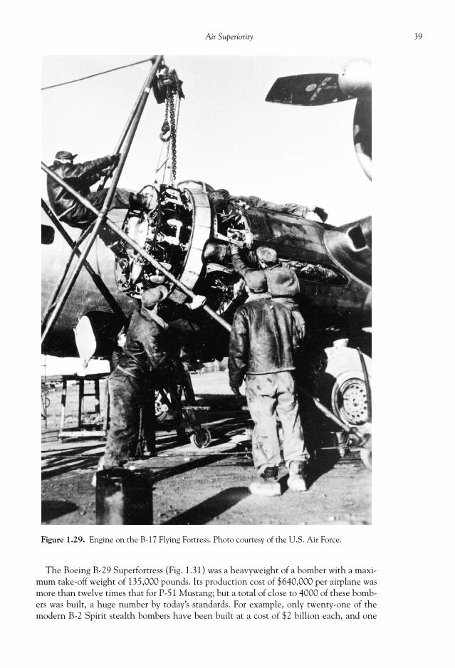
39Air Superiority
The Boeing B-29 Superfortress (Fig. 1.31) was a heavyweight of a bomber with a maxi-mum take-off weight of 135,000 pounds. Its production cost of $640,000 per airplane wasmore than twelve times that for P-51 Mustang; but a total of close to 4000 of these bomb-ers was built, a huge number by today’s standards. For example, only twenty-one of themodern B-2 Spirit stealth bombers have been built at a cost of $2 billion each, and one
Figure 1.29. Engine on the B-17 Flying Fortress. Photo courtesy of the U.S. Air Force.
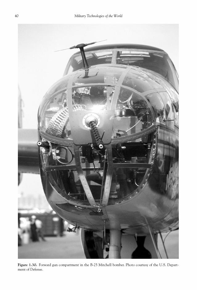
40 Military Technologies of the World
Figure 1.30. Forward gun compartment in the B-25 Mitchell bomber. Photo courtesy of the U.S. Depart-ment of Defense.
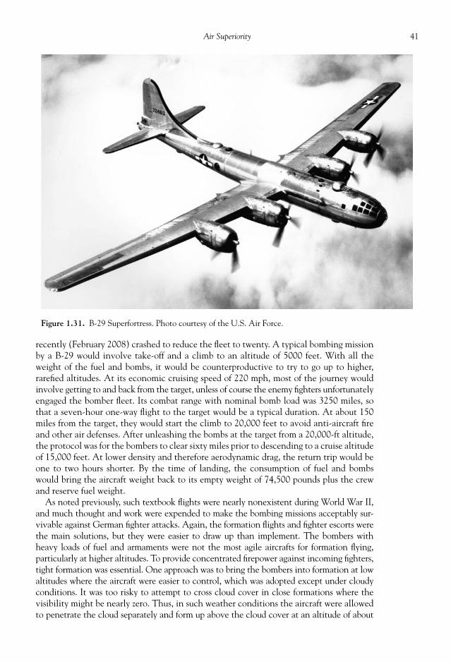
41Air Superiority
recently (February 2008) crashed to reduce the fl eet to twenty. A typical bombing missionby a B-29 would involve take-off and a climb to an altitude of 5000 feet. With all theweight of the fuel and bombs, it would be counterproductive to try to go up to higher,rarefi ed altitudes. At its economic cruising speed of 220 mph, most of the journey wouldinvolve getting to and back from the target, unless of course the enemy fi ghters unfortunatelyengaged the bomber fl eet. Its combat range with nominal bomb load was 3250 miles, sothat a seven-hour one-way fl ight to the target would be a typical duration. At about 150miles from the target, they would start the climb to 20,000 feet to avoid anti-aircraft fi reand other air defenses. After unleashing the bombs at the target from a 20,000-ft altitude,the protocol was for the bombers to clear sixty miles prior to descending to a cruise altitudeof 15,000 feet. At lower density and therefore aerodynamic drag, the return trip would beone to two hours shorter. By the time of landing, the consumption of fuel and bombswould bring the aircraft weight back to its empty weight of 74,500 pounds plus the crewand reserve fuel weight.
As noted previously, such textbook fl ights were nearly nonexistent during World War II,and much thought and work were expended to make the bombing missions acceptably sur-vivable against German fi ghter attacks. Again, the formation fl ights and fi ghter escorts werethe main solutions, but they were easier to draw up than implement. The bombers withheavy loads of fuel and armaments were not the most agile aircrafts for formation fl ying,particularly at higher altitudes. To provide concentrated fi repower against incoming fi ghters,tight formation was essential. One approach was to bring the bombers into formation at lowaltitudes where the aircraft were easier to control, which was adopted except under cloudyconditions. It was too risky to attempt to cross cloud cover in close formations where thevisibility might be nearly zero. Thus, in such weather conditions the aircraft were allowedto penetrate the cloud separately and form up above the cloud cover at an altitude of about
Figure 1.31. B-29 Superfortress. Photo courtesy of the U.S. Air Force.
42 Military Technologies of the World
8000 feet using radio signals. It could take up to one hour for the formation to be completed,which consumed time and also precious fuel. Once in formation, the pilots needed to be vigi-lant to keep the level, distance, and speed to maintain formation, leading to extra pilot fatigue.Another operational diffi culty was making turns, as the entire formation needed to be coordi-nated to avoid running into one another and the aircraft on the wings had diffi culty seeing thelead aircraft in some formations. Thus, fl ight routes to avoid fl ak (anti-aircraft fi re) zones werepreplanned with a minimum amount of maneuvers to get to and from the target area.
A number of fl ight formations were experimented with to optimize the defense andfl ight maneuvers. The U.S. 8th Air Force used different formations as the air battle situa-tion evolved. In one formation, for example, eighteen bombers were designated as abomber group and divided into three squadrons of six aircraft each. Each squadron of sixbombers fl ew in a 1 (front, lead)-3(middle)-2 (rear) staggered formation with the leadaircraft at the center left and front of the formation. The lead squadron fl ew ahead of thetwo squadrons that were 500 feet below and above the lead squadron. This formation al-lowed wide gun coverage, while affording visual contact among the aircraft. Later, suchbomber groups could be combined, where four groups would be sent in a bombing mission.Each group would then be separated by a distance of 1.5 miles from one another, and alsostaggered in altitude by 1000 feet.
CLASSIC FIGHTER TACTICS
The range and lethality of modern air-to-air missiles tend to decide aerial battles wellbeyond the visual range. However, during World Wars I and II and in many confl icts after-ward, the dogfi ghts in the air frequently determined the fate of one pilot or the other. Asthe speed and performance of the aircraft increased, it took a level of physical and mentalacumen as required by few other tasks to become profi cient in shooting down opposingaircraft while being exposed to the same risk. Mastery of tactics and maneuvers duringdirect engagements are still emphasized in most pilot training programs, although in re-cent years there have been few confl icts in which opposing air forces with similar level ofaircraft and pilot preparedness have met in the air. Some of the maneuvers originate fromWorld War II or even earlier in spite of the dramatic changes in the aircraft performance.Also, a modern aircraft gun or cannon is capable of fi ring 20 mm rounds at 6000 roundsper minute with a muzzle velocity of 3300 ft/s. In addition, the pilot is equipped with anarray of close- and long-range air-to-air missiles. The weaponry, speed, and maneuverabil-ity of modern jet fi ghters combined with the skills of the pilots make the modern dogfi ghtsan extreme test of human and machine capabilities.
Table 1.6 shows some of the major aircraft guns used by different jet fi ghters. We can seethat the U.S. jet aircraft are superior in terms of the rounds carried, rate of fi re, and themuzzle velocity. The GE M61 cannons are the primary gun on U.S. fi ghter aircraft, usedby nearly all of the major fi ghter aircraft in the last fi ve decades. M61 is also known as theVulcan or Gatling gun, with the latter name in reference to the multibarrel design by Dr.Gatling back in the mid-nineteenth century. The original design was hand-cranked torotate the barrels so that each barrel could independently undergo a fi ring cycle. This hasthe effect of multiplying the rate of fi re as well as reducing the heating and wear on thebarrels. The aircraft guns are of course mechanically driven, using hydraulics or electricalmotor, requiring 35 hp at the full rate of fi re. The maximum rate of fi re is 6600 per minute,but the fi re rate of either 6000 or 4000 is used. Six identical barrels are mounted on a drumbreech base that rotates in the counter-clockwise direction when viewed from behind thegun (the preferred position when facing this weapon). The rotating drum breech is set in
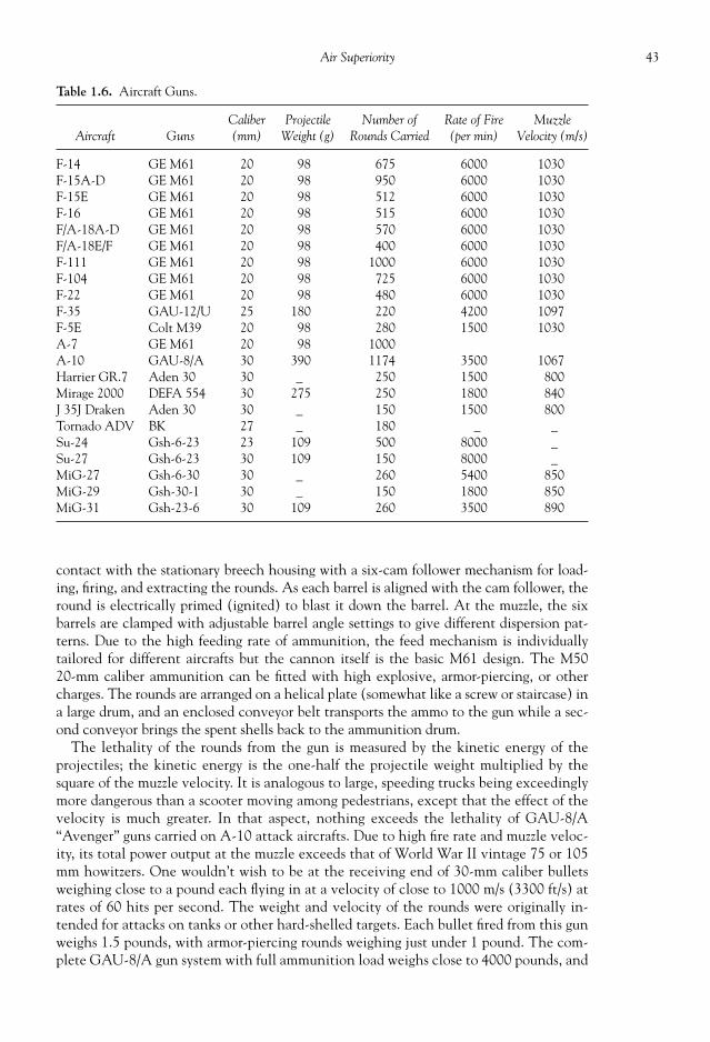
43Air Superiority
contact with the stationary breech housing with a six-cam follower mechanism for load-ing, fi ring, and extracting the rounds. As each barrel is aligned with the cam follower, theround is electrically primed (ignited) to blast it down the barrel. At the muzzle, the sixbarrels are clamped with adjustable barrel angle settings to give different dispersion pat-terns. Due to the high feeding rate of ammunition, the feed mechanism is individuallytailored for different aircrafts but the cannon itself is the basic M61 design. The M5020-mm caliber ammunition can be fi tted with high explosive, armor-piercing, or othercharges. The rounds are arranged on a helical plate (somewhat like a screw or staircase) ina large drum, and an enclosed conveyor belt transports the ammo to the gun while a sec-ond conveyor brings the spent shells back to the ammunition drum.
The lethality of the rounds from the gun is measured by the kinetic energy of theprojectiles; the kinetic energy is the one-half the projectile weight multiplied by thesquare of the muzzle velocity. It is analogous to large, speeding trucks being exceedinglymore dangerous than a scooter moving among pedestrians, except that the effect of thevelocity is much greater. In that aspect, nothing exceeds the lethality of GAU-8/A“Avenger” guns carried on A-10 attack aircrafts. Due to high fi re rate and muzzle veloc-ity, its total power output at the muzzle exceeds that of World War II vintage 75 or 105mm howitzers. One wouldn’t wish to be at the receiving end of 30-mm caliber bulletsweighing close to a pound each fl ying in at a velocity of close to 1000 m/s (3300 ft/s) atrates of 60 hits per second. The weight and velocity of the rounds were originally in-tended for attacks on tanks or other hard-shelled targets. Each bullet fi red from this gunweighs 1.5 pounds, with armor-piercing rounds weighing just under 1 pound. The com-plete GAU-8/A gun system with full ammunition load weighs close to 4000 pounds, and
Table 1.6. Aircraft Guns.
Aircraft GunsCaliber(mm)
ProjectileWeight (g)
Number ofRounds Carried
Rate of Fire(per min)
MuzzleVelocity (m/s)
F-14 GE M61 20 98 675 6000 1030F-15A-D GE M61 20 98 950 6000 1030F-15E GE M61 20 98 512 6000 1030F-16 GE M61 20 98 515 6000 1030F/A-18A-D GE M61 20 98 570 6000 1030F/A-18E/F GE M61 20 98 400 6000 1030F-111 GE M61 20 98 1000 6000 1030F-104 GE M61 20 98 725 6000 1030F-22 GE M61 20 98 480 6000 1030F-35 GAU-12/U 25 180 220 4200 1097F-5E Colt M39 20 98 280 1500 1030A-7 GE M61 20 98 1000A-10 GAU-8/A 30 390 1174 3500 1067Harrier GR.7 Aden 30 30 _ 250 1500 800Mirage 2000 DEFA 554 30 275 250 1800 840J 35J Draken Aden 30 30 _ 150 1500 800Tornado ADV BK 27 _ 180 _ _Su-24 Gsh-6-23 23 109 500 8000 _Su-27 Gsh-6-23 30 109 150 8000 _MiG-27 Gsh-6-30 30 _ 260 5400 850MiG-29 Gsh-30-1 30 _ 150 1800 850MiG-31 Gsh-23-6 30 109 260 3500 890
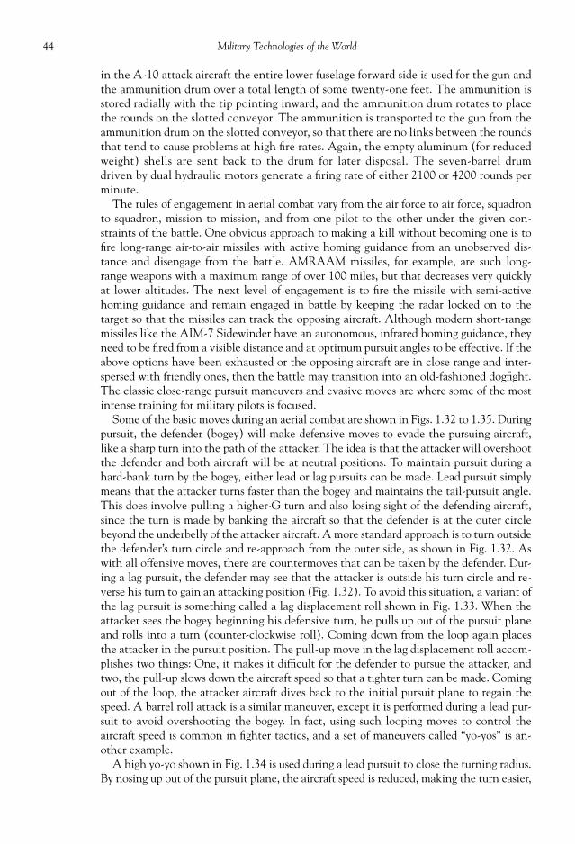
44 Military Technologies of the World
in the A-10 attack aircraft the entire lower fuselage forward side is used for the gun andthe ammunition drum over a total length of some twenty-one feet. The ammunition isstored radially with the tip pointing inward, and the ammunition drum rotates to placethe rounds on the slotted conveyor. The ammunition is transported to the gun from theammunition drum on the slotted conveyor, so that there are no links between the roundsthat tend to cause problems at high fi re rates. Again, the empty aluminum (for reducedweight) shells are sent back to the drum for later disposal. The seven-barrel drumdriven by dual hydraulic motors generate a fi ring rate of either 2100 or 4200 rounds perminute.
The rules of engagement in aerial combat vary from the air force to air force, squadronto squadron, mission to mission, and from one pilot to the other under the given con-straints of the battle. One obvious approach to making a kill without becoming one is tofi re long-range air-to-air missiles with active homing guidance from an unobserved dis-tance and disengage from the battle. AMRAAM missiles, for example, are such long-range weapons with a maximum range of over 100 miles, but that decreases very quicklyat lower altitudes. The next level of engagement is to fi re the missile with semi-activehoming guidance and remain engaged in battle by keeping the radar locked on to thetarget so that the missiles can track the opposing aircraft. Although modern short-rangemissiles like the AIM-7 Sidewinder have an autonomous, infrared homing guidance, theyneed to be fi red from a visible distance and at optimum pursuit angles to be effective. If theabove options have been exhausted or the opposing aircraft are in close range and inter-spersed with friendly ones, then the battle may transition into an old-fashioned dogfi ght.The classic close-range pursuit maneuvers and evasive moves are where some of the mostintense training for military pilots is focused.
Some of the basic moves during an aerial combat are shown in Figs. 1.32 to 1.35. Duringpursuit, the defender (bogey) will make defensive moves to evade the pursuing aircraft,like a sharp turn into the path of the attacker. The idea is that the attacker will overshootthe defender and both aircraft will be at neutral positions. To maintain pursuit during ahard-bank turn by the bogey, either lead or lag pursuits can be made. Lead pursuit simplymeans that the attacker turns faster than the bogey and maintains the tail-pursuit angle.This does involve pulling a higher-G turn and also losing sight of the defending aircraft,since the turn is made by banking the aircraft so that the defender is at the outer circlebeyond the underbelly of the attacker aircraft. A more standard approach is to turn outsidethe defender’s turn circle and re-approach from the outer side, as shown in Fig. 1.32. Aswith all offensive moves, there are countermoves that can be taken by the defender. Dur-ing a lag pursuit, the defender may see that the attacker is outside his turn circle and re-verse his turn to gain an attacking position (Fig. 1.32). To avoid this situation, a variant ofthe lag pursuit is something called a lag displacement roll shown in Fig. 1.33. When theattacker sees the bogey beginning his defensive turn, he pulls up out of the pursuit planeand rolls into a turn (counter-clockwise roll). Coming down from the loop again placesthe attacker in the pursuit position. The pull-up move in the lag displacement roll accom-plishes two things: One, it makes it diffi cult for the defender to pursue the attacker, andtwo, the pull-up slows down the aircraft speed so that a tighter turn can be made. Comingout of the loop, the attacker aircraft dives back to the initial pursuit plane to regain thespeed. A barrel roll attack is a similar maneuver, except it is performed during a lead pur-suit to avoid overshooting the bogey. In fact, using such looping moves to control theaircraft speed is common in fi ghter tactics, and a set of maneuvers called “yo-yos” is an-other example.
A high yo-yo shown in Fig. 1.34 is used during a lead pursuit to close the turning radius.By nosing up out of the pursuit plane, the aircraft speed is reduced, making the turn easier,

45Air Superiority
and also the attacker used the vertical space to close in on the bogey. A low yo-yo accom-plishes the same relative position except the dive is followed by a climb up to the pursuitplane as shown in Fig. 1.34.
The real situation during the aerial battle usually is not as simple as the above examples.The defender will make various maneuvers to reverse the attacker-defender position. Oneof the ways for achieving this reversal is the scissors technique, shown in Fig. 1.35. Duringa fl at scissors, the defender makes a sharp turn to cause an overshoot by the attacking air-craft, then turns back into the attacker to gain a six o’clock position. The attacker re-sponds by turning into the defender, again causing an overshoot by the defending aircraft.This sequence can go on until one of the fi ghters makes a mistake or disengages. The fl atscissors maneuvers are made in a horizontal pursuit plane, where the turns are made bybanking the aircraft 90 degrees and pulling up on the control stick. To make the reverseturn, the aircraft needs to bank at –90 degrees. To make a more effective turn and also slowthe aircraft, a rolling scissors technique is used. As in high and low yo-yos, aircraft will losespeed during pull-up climbs and gain speed during dives. This is exactly what happens onthe ground as well, when a vehicle is going up-slope it will lose speed and vice versa during
Figure 1.32. Lead and lag pursuits.

46 Military Technologies of the World
downhill runs. During a rolling scissors maneuver, the defender pulls up and at the sametime turns into the attacking aircraft’s trajectory, to cause an overshoot. This maneuverrequires the aircraft to roll and follow a curve along the surface of an imaginary barrel, andtherefore this maneuver is sometimes called a barrel roll. The attacking aircraft again re-sponds by making a similar barrel roll, to regain the advantage. A defensive barrel rollpointing vertically downward to gain speed and therefore movement away from the at-tacking aircraft is called a defensive spiral.
Figure 1.33. Lag-pursuit roll.

47Air Superiority
So the pilot does what is in his skill set to gain an attacking position or evade the attackingaircraft using a variety of moves. Once he gets into an attacking position, he can now makeuse of the weapons control technology embedded into the cockpit. The pilot’s eyes will belocked on the target through the heads-up display (HUD) directly in front of him. Let ustherefore look at some of the electronic and control technologies in military aircrafts.
Figure 1.34. High yo-yo and low yo-yo maneuvers.

48 Military Technologies of the World
AVIONICS AND CONTROLS
The cockpit of modern military aircraft is a busy place with all the instruments, weaponscontrol, navigation, and communication gears. Fig. 1.37 shows the cockpit of a high-altitude reconnaissance aircraft, the U-2 “Dragonlady.” It has some of the modern digitaldisplays such as the artifi cial horizon and multifunction display showing the navigationmap. A few back-up analog gauges are also seen for essential instruments.
The layout and the instrumentation vary from aircraft to aircraft, and many of the gaugesare now embedded into the multifunction digital display. However, the essential compo-nents can be found in all of the aircrafts. We can start by looking at a classic instrumentpanel of the F-4 Phantom jets, in Fig. 1.39. Starting from the left-hand side of the pilot, thearmament safety override switch (1 in Fig. 1.39) is found near the pilot’s seat. Number 2 isthe anti-G suit control valve. To overcome the effect of high G-forces, fi ghter pilots wear apressurized suit to prevent blood from being pushed to one side of the body. The panel thatcontrols the suit air vent is next on the left instrument panel (3). Number 4 is the fuel con-trol panel, to select from different fuel tank locations for center of gravity adjustments or toeject the fuel altogether. Number 6 is the eject light and switch. There are two engines onthe F-4 Phantom aircraft, and therefore two engine controls (7 for the outboard engine and11 for the inboard one). The throttle handle is controlled by the left hand (8). Numbers 9
Figure 1.35. Scissors maneuvers.
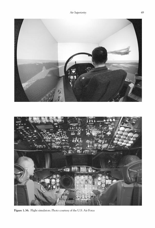
49Air Superiority
Figure 1.36. Flight simulators. Photo courtesy of the U.S. Air Force

50 Military Technologies of the World
and 10 are the left utility and vertical panels. Number 12 shows the handle that deploys thedrag chute for short landing situations. The automatic controls are found on panel 13, whilethe intercom controls are on panel 14. Number 15 shows the controls for the auxiliary arma-ments. There are many dials and gauges on the classic F-4 cockpit: true airspeed indicator(16), angle-of-attack indicator (17), landing gear warning light (18), airspeed and Machnumber indicator (19), attitude-direction indicator (20), magnetic compass (22), altimeter(24), and fuel quantity indicator (25). Number 21 is the optical sight unit for aiming thecannons. On modern aircraft, the optical sight is replaced by the heads-up display (HUD)discussed later. The main radar scope is in the middle of the instrument panel (23). Numbers30 to 33 are the engine gauges—engine fuel fl ow indicator (31), tachometer (32), and ex-haust gas temperature indicator (33). Since there are two engines, there are two of eachgauge. The vertical velocity indicator gives the rate of climb or descent in feet per min.Number 36 is a clock. The remainder of the components is listed below.
37: Navigation function selector panel 38: Horizontal situation indicator 39: Multiple weapons control panel 40: Oil pressure indicator 41: Rudder pedal adjustment crank 42: Pneumatic pressure indicator 43: Hydraulic pressure indicator 44: Accelerometer (shows the number of Gs the aircraft is pulling) 45: Bomb control panel 46: Standby altitude indicator 47: Missile control panel
Figure 1.37. A modernized cockpit of U-2 Dragonlady. Photo courtesy of the U.S.Air Force.

51Air Superiority
Figure 1.38. Cockpit of now-decommissioned SR-71 Blackbird. Photo courtesy of the U.S. Departmentof Defense.

52 Military Technologies of the World
48: Missile status panel 49: Radar altimeter (give the altitude using the radar refl ection signal from the ground) 50: Landing gear checklist 51: Generator control panel 52: Defog/foot heat control panel 53: Essential circuit breaker panel 54: Temperature control panel55: Cockpit lights control panel 56: Indexer light control panel 57: Wing fold control panel 58: Utility electrical receptacle 59: Exterior lights control panel 60: IFF (identifi cation friend or foe) control panel 61: Compass system control panel 62: Com-nav group control panel 63: Emergency brake handle 64: Fuse function control panel
So quite a lot is packed into a small space, and the use of dialed gauges is pretty muchthe same as in World War II aircraft. The airspeed, altimeter, and rate of climb gauge arecalled barometric instruments because they rely on pressure measurements. For example,the standard air pressure is a known function of altitude with some minor adjustments
Figure 1.39. Instrumentation on a classic cockpit of F-4 Phantom.

53Air Superiority
depending on the local pressure. For example, from the standard 1 atmospheric pressure(101.325 kPa or 14.7 psi), the pressure decreases by approximately 10 kPa for every 800meter increase in altitude to about 4000 meters, beyond which it decreases more gradually.Thus, at 30,000 feet, for example, the pressure is less than one-third of the pressure at sealevel. This pressure change is measured by pressure transducers and calibrated back to al-titude in modern digital altimeters. The rate of change of pressure, and therefore altitude,is converted to display the rate of climb or dive. The air speed gauge is based on the so-called Pitot-static probe measurements of static and stagnation pressures. The static pres-sure is the pressure of the moving air, while the stagnation pressure corresponds to thepressure reached when the incoming airspeed rams into the pressure sensor and thus in-creases the pressure. The stagnation pressure probe, or the Pitot tube, is thus oriented to-ward the incoming air. The difference in the static and stagnation pressure is proportionalto the square of the air velocity, which is calibrated to give the air speed after accountingagain for the altitude effect on air density. The artifi cial horizon, or the attitude indicator,give a visual display of the aircraft pitch and roll angles based on the gyroscope references.The artifi cial horizon is a demarcation between the blue and brown backgrounds to indi-cate sky and land, respectively, and pitch scale marks move up and down with respect tothe aircraft symbol at the center to indicate the pitch angle. The rotation of the artifi cialhorizon then is the measure of the aircraft roll angle. The horizontal situation indicatorgives the aircraft heading information by using the gyroscope or magnetic compass. Typi-cally, distance readouts from beacon signals is embedded on this indicator.
The use of the analog, dialed gauges was prevalent even in the early versions of the F-15Eagles, as shown in Fig. 1.40. Nowadays, most of the gauge readings are incorporated intothe multifunction display (MFD) except for a few backup gauges for critical indicators (seeFigs. 1.41 to 1.43). MFD combines many of the functions of the classic dials and gauges,and much more, so that the pilot can select and view the overall aircraft conditions foreach category. The display modes include primary fl ight display, navigation, plan positionindicator, engine, aircraft confi guration, map, station keeping equipment, engine operationdisplay, compass, radar/target display, and weapons control. For example, the primary fl ightdisplay including the horizontal situation display (artifi cial horizon) and the compass areshown in the main MFD in the middle of the cockpit in the fi gure, while the left MFDshows the map display. To allow the pilot to maintain visual contact with the surroundingthrough the canopy while being able to monitor some of the critical information, a heads-updisplay (HUD) is mounted directly in front of the pilot, as shown in the fi gures.
A HUD is now an essential piece of display equipment in military aircraft, and a lot ofinformation can be selected and displayed. Primary fl ight data, weapons targeting, andother information can be displayed on the HUD. The primary fl ight data include the fl ightpath vector (also known as the velocity vector), the artifi cial horizon, speed, altitude,heading, vertical speed (rate of climb/dive), and angle of attack. The speed, altitude, andheading are shown either in numerical values or on a linear scale with a moving cursor.Navigation information is also shared between the HUD and MFD, and this includes lat-eral and vertical guidance to the preselected fl ight plan, the next waypoint latitude andlongitude, direction, and range/time to the next waypoint.
Two examples of the HUD display are shown in Fig. 1.44. The left HUD display is forair-to-air gun mode. The horizontal scale at the top is the compass heading, now showinga 120o heading. A plus (+) sign below the heading scale shows that the master arm isturned on. The horizontal line with a “W” in the middle is the aircraft attitude or the bankangle. The velocity vector, the circle with three ticks, shows where the aircraft is headed(now showing a dive to the right). The left vertical scale shows the aircraft speed while theright vertical scale is the altitude scale (now showing 430 ft). The inner, right vertical

54 Military Technologies of the World
Figure 1.41. F-16 cockpit. Photo courtesy of the U.S. Department of Defense.
Figure 1.40. Cockpit of F-15A (1970s). 1/2. Hook switch/panel; 3. Flap indicator; 4.Fire warning panel; 5. Weapons control panel; 6. Gear handle; 7. Pitch ratio indicator;8/9. Pitch ratio switch/panel; 10. Radio call panel; 11. Radar scope; 12. Air speed indica-tor; 13. Angle of attack indicator; 14. Accelerometer; 15. Emergency jettison switch;16/17. Steer mode switch/panel; 18. HUD control panel; 19. Altitude indicator; 20.Horizontal situation indicator; 21. Air speed indicator (backup); 22. Altitude indicator(backup); 23. Altimeter (backup); 24/25/26/27. Master mode panel/AC mode button/ADI mode button/V1 mode button; 28. Beacon light control; 29. TEWS displays; 30.Altimeter; 31. Vertical velocity; 32. Clock; 33. Left engine tachometer; 34. Right enginetachometer; 35. Left engine temperature; 36. Right engine temperature; 37. Left enginefuel fl ow; 38. Right engine fuel fl ow; 39. Left nozzle position; 40. Right nozzle position;41. Display select button; 42. PC1 indicator; 43. PC2 indicator; 44/45. Utility indicator/Oil hydraulics panel; 46. Left engine oil pressure; 47. Right engine oil pressure; 48. Fuelquantity indicator; 49. JFS panel; 50. Cabin pressure gauge; 51. UHF remote panel; 52.IFF remote panel; 53. Heads-up display (HUD); 54. Gun sight camera control panel.

55Air Superiority
Figure 1.42. Another photograph of the F-16 cockpit. Photo courtesy of the U.S. Department of Defense.
scale shows the radar ranging, with the arrow showing the current distance to the target ofabout 3000 ft. The range is also shown on the aiming reticle, where the solid line is atthree ticks from the vertical. The small rectangle shows the target location, locked by theradar. The radar calculates the distance, speed, and relative motion of the target and air-craft, to locate the aiming reticle. In some HUD displays, the impact line of the gun is alsocontinuously computed and displayed. Since the aircraft gun is fi xed to the forward direc-tion of the aircraft, the pilot must guide the aircraft until the aiming reticle coincides withthe target rectangle. The number below the left vertical scale shows the number of roundsremaining (799). The HUD display in on the right shows the air-to-ground or the CDIP(continuous displayed impact point) mode used for basic bombing missions. Now the aim-ing reticle (called the “pipper”) shows where the bombs will fall if released. This point iscomputed from the data on aircraft motion, height, bomb ballistics, bomb release veloc-ity, and estimated wind speed and direction. Since an accurate height is essential, thebarometric measurement may be replaced by laser or radar altimetry. So again, the pilotmust guide the aircraft to overlap the pipper on the target, press the automatic bomb re-lease button, and then pull up. The horizontal lines at the top and bottom of the HUDindicate the pitch angles. If the velocity vector lies at the horizontal line with number “5”next to it, it means the pitch angle is 5 degrees from the horizontal. Other display informa-tion includes the aircraft angle of attack, weapons mode, and safe pass height. The safepass height indicates the fragmentation range, and the pilot should avoid releasing thebomb if the pipper comes too close to this height.
Photographs of the HUD displays on the F-18/A Hornet are shown in Figs. 1.45 and1.46. It is in a primary fl ight display mode, simply showing the aircraft attitude line, withheading scale and pitch scales. For night fl ights, a synthetic image of the surroundings

56 Military Technologies of the World
from the FLIR (forward looking infrared) or synthetic aperture radar can be superimposedon the HUD display to show the outside terrain and objects, as shown in Fig. 1.47.
The military does not seem to spare anything when it comes to assisting its pilots inmaximizing their abilities to engage in battle through the use of emerging technology. Theintegration of the synthetic image onto the heads-up display gives the pilot an ability tocarry out a mission regardless of the weather, day or night. If the pilot’s pair of good eyesand a crude radio were the only link to the outside world for World War II pilots, nowadaysthe total sensory system of a jet fi ghter ranges from the radars, FLIR imager, jammer pods,
Figure 1.43. Cockpit design in the F/A-18 fl ight simulator.

57Air Superiority
RWR (radar warning receiver), IFF data links,ECM (electronic countermeasure) pod, toUHF radios.
Human vision, while being quite usefulfor daily tasks, is actually quite limited inits spectral range, meaning that we canonly see from red to violet. In the broadscheme of things, red to violet covers thevisible wavelength range of 400 nm (vio-let) to 760 nm (red). A nanometer (nm) isone-billionth of a meter. The total electro-magnetic spectrum can go from gamma andX-rays of sub-nanometer wavelengths tomicrowave and radio waves with 1 to 1000 mwavelength. Radio waves are used for com-munications, and microwaves are used forradars. Microwaves have certain advan-tages for the probing of the sky. Microwavesare easily generated from oscillating electricfi elds and can propagate long distances in the atmosphere at the speed of light. But mostimportantly, most objects (rain drops, water surfaces, metals, etc.) refl ect a lot of the in-coming microwaves. Also, returning microwaves can be detected using the same appara-tus. So, a radar scanning different directions will fi nd a refl ecting object, and the distanceto the object can be determined by how long it took the radar signal to hit and return fromthe object. The radar signals, as well as other electromagnetic waves, travel at a constantspeed (speed of light = 300,000 km/s) in air. Also, the speed of the object can be found
Figure 1.44. Examples of HUD displays.
Figure 1.45. A heads-up display on F/A-18. Photo courtesyof the U.S. Navy.

58 Military Technologies of the World
because the radar wave frequency will be slightly shifted bythe relative motion between the radar and the object. Radarsare therefore active devices, producing and sending out prob-ing signals. Typical military radars have ranges in excess of100 miles, and horizontal coverage of 120 degrees (1/3 of theentire horizon) and vertical scan of +/– 9 degrees.
The FLIR system is essentially a digital camera, except itcan see in the infrared range. As noted above, human visionworks by looking at the visible light that is refl ected from ob-jects. The only problem is that when there is no sun or moonto illuminate the objects, human vision is quite limited. Infra-red imaging works because even in the absence of any illumi-nation all objects radiate in the infrared range (wavelengthsgreater than 760 nm). At typical ambient temperatures, mostof the infrared radiation will be in the 5 to 20 μm range, andweak. So, IR-sensitive sensors with high gains are used toview the outside world even in the absence of illuminations.
Why can’t the normal digital cameras do this? The sensors in common devices only re-spond to visible light, and also the lenses will not transmit infrared radiation. In fact, IRcameras are expensive because of the high cost of the IR sensors and optical components.
The IFF is a radio transponder that sends out signals. An IFF unit responds on receivinga signal from another source by sending back a coded signal, which is interpreted by the
Figure 1.46. Another view through the HUD of the F/A-18. Photo courtesy of the U.S. Department of Defense.
Figure 1.47. A heads-up display withsynthetic image of the terrain. Photocourtesy of the U.S. Air Force.

59Air Superiority
sender to determine whether the aircraft in range is friend or foe without visual contact.More advanced identifi cation systems have been or are being developed using specifi cradar signatures, and this is an active research and development area involving electricaland computer engineers.
AERODYNAMICS
Now that we have looked at a number of weapon technologies, let us look at somethingthat is more fundamental to fi ghter aircraft, like how they fl y and maneuver in the sky. As theWright brothers proved for the fi rst time in history, a wing or set of wings can generate anupward force or lift. This is due to the pressure difference between the fl ows at the top andbottom of the wings. Wings—more precisely airfoils—are contoured so that the fl ow musttravel a longer path (and therefore must travel faster) around the top surface. For the air fol-lowing these streamlines, the pressure goes down when the velocity goes up and vice versa. Sothe top surface is at a low pressure and the bottom at a high pressure, resulting in a net upwardforce called lift. The faster the air speed, the larger this pressure difference becomes and there-fore more lift for the aircraft. Also, larger wing area, density, and shape of the airfoil affect thelift characteristics. So this lift force overcomes the weight of the aircraft to allow it to fl y.
When we fl y in commercial airliners, if we are seated at the row close to the trailing edgeof the wing, we can see the wing fl aps go down during take-off and landing and also hearthe hydraulics to deploy these fl aps. Flaps increase the wing area, but they are also designedto control the air fl ow to follow the wing contour at the take-off and landing conditions.For military aircraft, such elaborate fl ap design is both cumbersome and also not as neces-sary because the much more powerful engines can generate very large air speeds quickly. Sothey use different approaches to maximize lift during take-off and landing. The F-16, forexample, has a fi xed wing, but its wing profi le can be changed both at the leading and trail-ing edge depending on the fl ight conditions. Fig. 1.48 shows the various profi le changescontrolled by an onboard computer for the F-16 aircraft. During take-off and landing, max-imum thrust is required, and therefore the trailing-edge fl ap is down a full 20 degrees. Dur-ing ground roll, the aircraft is moving parallel to the ground, and so the leading-edge fl apis not deployed. Once off the ground, the aircraft noses up. That increases the angle of
Figure 1.48. F-16 wing profi le confi gurations at different fl ight phases.

60 Military Technologies of the World
attack, the angle of the aircraft with respect to the incoming air. To accommodate this airfl ow coming from underneath, the leading-edge fl ap is down 15 degrees. During high-speedcruise, neither of the fl aps is needed, and both fl aps are retracted to pose minimum obstruc-tion to the fl ow. During tight maneuvers (as in dogfi ghts described above), the leading-edgefl ap is again deployed so that the aircraft is less likely to stall.
Another way to optimize the wing aerodynamics for the fl ight condition is to use the fullvariable-geometry wing, as in the F-14 Tomcat and the European fi ghter Tornado. The entirewing is rotated to a swept-back position during high-speed cruise to minimize and extended toa nearly straight position during take-off and landing to maximize the wing area. During ma-neuvers, the wing actually rotates to maximize its effectiveness. The variable-geometry wingthus provides the best of short take-off/landing, maneuverability, high-speed performance, andcrew comfort in a single aircraft, at the expense of complex control and actuators.
The lift force counterbalances the weight of the aircraft, except that most of the timethe lift is not exactly located at the center of gravity for the aircraft as shown in Fig. 1.49.This will obviously make the aircraft unstable and simply fl ip the aircraft. So aircraft havehorizontal stabilizers, or the elevators, to balance the forces. In the horizontal direction,the aircraft also encounters aerodynamic drag which is balanced by the thrust force duringconstant-speed cruise. The balance force of elevators can be adjusted by changing theirangles through rotation, and this will control the pitch of the aircraft. The F/A-22 Raptoris equipped with a clipped delta wing with the leading-edge fl ap, fl aperons, and ailerons atthe trailing edge. The leading-edge fl ap and the trailing-edge fl aperon serve the same pur-pose as the ones shown in Fig. 1.49: They are rotated to optimize the aircraft’s aerody-namic lift. The fl aperons and ailerons also can be fl ipped in opposite directions on the two
Figure 1.49. Aerodynamic forces and surfaces on the F/A-22 Raptor (front) and F-15 Eagle (back). Photocourtesy of the U.S. Air Force.
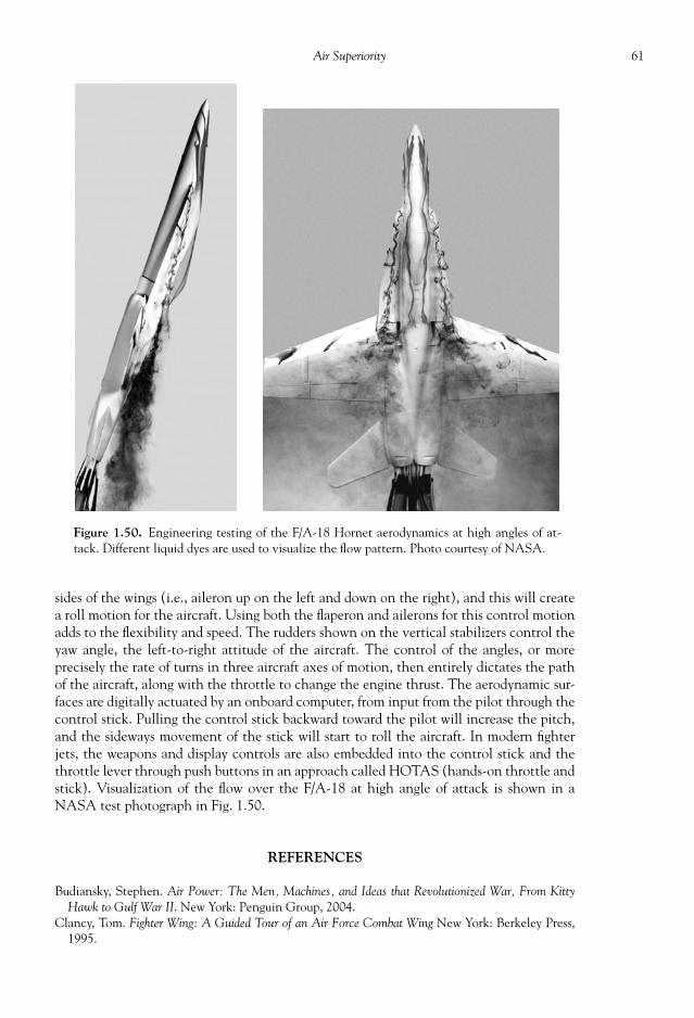
61Air Superiority
Figure 1.50. Engineering testing of the F/A-18 Hornet aerodynamics at high angles of at-tack. Different liquid dyes are used to visualize the fl ow pattern. Photo courtesy of NASA.
sides of the wings (i.e., aileron up on the left and down on the right), and this will createa roll motion for the aircraft. Using both the fl aperon and ailerons for this control motionadds to the fl exibility and speed. The rudders shown on the vertical stabilizers control theyaw angle, the left-to-right attitude of the aircraft. The control of the angles, or moreprecisely the rate of turns in three aircraft axes of motion, then entirely dictates the pathof the aircraft, along with the throttle to change the engine thrust. The aerodynamic sur-faces are digitally actuated by an onboard computer, from input from the pilot through thecontrol stick. Pulling the control stick backward toward the pilot will increase the pitch,and the sideways movement of the stick will start to roll the aircraft. In modern fi ghterjets, the weapons and display controls are also embedded into the control stick and thethrottle lever through push buttons in an approach called HOTAS (hands-on throttle andstick). Visualization of the fl ow over the F/A-18 at high angle of attack is shown in aNASA test photograph in Fig. 1.50.
REFERENCES
Budiansky, Stephen. Air Power: The Men, Machines, and Ideas that Revolutionized War, From KittyHawk to Gulf War II . New York: Penguin Group, 2004.
Clancy, Tom. Fighter Wing: A Guided Tour of an Air Force Combat Wing New York: Berkeley Press,1995.

62 Military Technologies of the World
Crawford, Steve. Twenty-First Century Warplanes: The World’s Most Potent Military Aircraft .St. Paul, MN: MBI Publishing Company, 2002.
Laur, Col. Timothy M. and Steven L. Llanso. Encyclopedia of Modern U.S. Military Weapons . NewYork: Berkeley Books, 1995.
The New Face of the War: Air Combat . New York: Time-Life Books, 1991. Price, Alfred. Combat Developments in World War Two: Fighter Aircraft . London: Arms and Armor
Press, 1986. Price, Alfred. Combat Developments in World War Two: Bomber Aircraft . London: Arms and Armor
Press, 1986. For further information on the B-1B bomber, see the following Web page: www.fas.org/nuke/guide/usa/bomber/b-1b.htm and en.wikipedia.org/wiki/B-1_Lancer.

MEDIA COVERAGE OF world events in the recent past, including the wars in Iraq, hasshown the effectiveness of modern guided missiles and smart bombs zeroing on the target.Some of the broadcast footage included video transmissions from the missile itself or fromthe delivery aircraft as the guided projectile streams toward the laser-illuminated target.Targets as far away as 1000 miles and as small as a single-car garage have been hit withcruise missiles as if these missiles were individually guided by a human pilot. This kind ofweapons technology gave rise to the term “surgical strikes.” There are also missiles like thePatriot systems designed to perform high-speed intercepts of incoming missiles, and a sub-stantial amount of research and development is being expended on so-called ballistic mis-sile defense (BMD). BMD is a comprehensive defense program to provide a physicalumbrella against ballistic missiles presumed to carry nuclear or other weapons of mass de-struction, and one of the key components is the high-accuracy hypersonic projectile deliv-ery toward the incoming warheads. Some of the air-to-air missiles launched from fi ghteraircraft are of the fi re-and-forget type that lock on to the target from a distance of 100miles or farther and guide themselves while the launch vehicle engages other enemy tar-gets or simply disengages from the battle scene. One of the fi re-and-forget armaments, theAIM-54 Phoenix missile shown in Fig. 2.1, has a range of greater than 100 miles and aspeed exceeding 3000 mph. Shoulder-launched surface-to-air missiles like the U.S.-madeStinger (see Figs. 2.2(a) and (b)) are a legitimate threat for aircraft up to 15,700 ft (4500m). Intercontinental ballistic missiles (ICBM) carry nuclear warhead(s) on a global scaleand can be launched from the ground or from submarines. This array of airborne weaponrygives the commanders, and policy makers, unprecedented tactical and strategic advan-tages and options in conventional warfare.
The advantages gained from effective missile technology are evident. Large thrust canbe generated from a relatively small and inexpensive propellant charge, so that a sizablewarhead can be delivered over a long range and at high speeds. The missiles can thus belaunched from the relative safety of long distances, minimizing the exposure of the launchvehicle or personnel. This class of weapon systems can offset much larger and much moreexpensive systems, for example, accurately fi red rocket-propelled grenades can down lightarmored helicopters or land vehicles. An array of surface-to-air missiles, from shoulder-launched Stinger to ground-launched AMRAAM (Advanced Medium-Range Air-to-AirMissile) can in theory disable multimillion-dollar jets if these targets are locked onto bythe missile guidance systems in range. A variety of warheads can be loaded on these mis-siles to suit the targets. For anti-tank missiles like the AGM-114 Hellfi re missiles, thewarhead contains a conical-shaped explosive charge in a copper liner cone to blast a jet ofhigh-pressure gas through heavy armors in addition to the kinetic energy that the missile
CHAPTER
2
MISSILE TECHNOLOGY

64 Military Technologies of the World
Figure 2.1. AIM-54 Phoenix missile being launched from F-14 Tomcat. Photocourtesy of the U.S. Navy.
Figure 2.2 (a) and (b). Launch of a surface-to-air FIM-92Stinger missile. Photo courtesy of the U.S. Army.
carries at a velocity of 950 mph. Since theend of the World War II, nuclear warheadsinstalled on long-range ballistic missileshave continued to pose mutual threats amongformer Cold War adversaries and humanity.These nuclear weapons can be deliveredfrom ground-launched ICBMs, submarine-launched SLBMs, cruise missiles, and evenon artillery shells. The intercontinentalballistic delivery of the nuclear warheadsinvolves high-altitude, high-speed trajec-tories that can only be provided usingrocket thrusters.
The key components in missile technol-ogy are (1) the propulsion system, (2) theguidance unit, and (3) the armament.Rockets burning solid propellants are com-monly used as the propulsion system be-cause this type of propellants tend to bemost stable, cost-effective, and easiest tomaintain, but more sophisticated liquid-propellant rockets and gas-turbine enginesare also used for long-range and cruise mis-siles, respectively. There are numerous pas-sive and active guidance systems, rangingfrom heat-seeking sensors, active radars,and GPS (global positioning system) to ter-rain contour matching. Once the missile

65Missile Technology
reaches the target, delivered by the propulsion and the guidance system, then it is the ar-mament that determines the amount of damage. Conventional munitions are carried by amajority of missile weapons in use, although there still exists a large arsenal of nuclear andother weapons of mass destruction in the world deployable using tactical or strategic mis-sile platforms. In this chapter, we look into these technologies, as well as see how thetechnology is used in various weapon systems. However, before we delve into these topics,let us look at how it all began.
A BRIEF HISTORY OF MISSILE TECHNOLOGY
Rocketry for military use is believed to have begun in China. The “black powder” wasdiscovered before 900 CE in China and was used by the Chinese army to make crude fl amethrowers (“fi re lance”), grenades, siege weapons, and other devices that delivered shockeffects against the Mongols in the tenth century. There are references to the existence ofblack powder in Chinese documents dated as far back as 850 CE , and another Chinesedocument, “Wu Jing Zong Yao” (“Collection of the Most Important Military Techniques”),contains three different recipes for black powder—two for incendiary bombs to be usedduring siege and one for propelling bombs. A systematic military use of black powder isbelieved to have occurred in Kai Fung Fu, China, in 1232 CE through rack-launched bam-boo rockets described as “arrows of fi re.” The Chinese also developed cannons and usedblack powder to launch heavy projectiles. When Mongols conquered China in the 1270sand acquired the technology, the use of cannons and rockets powered by black powderbecame widespread in the East Asian warfare. Like most other technology discussed in thisbook, when it came to technology on which survival depended the dissemination wasquite rapid and widespread. The Arabs, being adjacent to Asia and also having been over-run by the Mongols, learned of the black powder in the thirteenth century. The Turks builtan enormous ninety-cm-bore cannon that fl ung 320 kg cannonballs over a mile. In Europesome years later, the use of black powder was predominantly in guns and cannons, whichdeveloped rapidly through the inventiveness of the people and the metallurgical know-how of that time.
Black powder consists of readily available ingredients—charcoal, sulfur, and saltpeter(potassium nitrate)—and was probably discovered by accident and perfected throughtrial-and-error. It acquires explosive characteristics only when fi nely ground and thor-oughly mixed to the right proportions. Saltpeter is a naturally occurring substance with awhite powdery appearance. It is an oxidation product of nitrogen-containing biologicalwaste formed in the presence of water and oxygen and has a chemical formula of KNO3 (Kstands for potassium, N nitrogen, and O oxygen). As we can see in its chemical formula,it is rich in oxygen content and serves as the oxidizer. To burn any fuel, we need both thefuel and oxygen, and saltpeter releases the needed oxygen when heated. The burning ofblack powder goes something like this:
2 parts saltpeter + sulfur + 3 parts charcoal � combustion products + nitrogen + heat
As we will see later, both the volume of the combustion product and the amount of heatare important for generating thrust to propel rocket devices.
The invention of the black powder has had a long-lasting and profound effect on threemajor applications, missiles, guns, and fi reworks. When packed inside a barrel, the blackpowder provided a near-instantaneous release of energy and high-pressure gas that hurledthe projectile to great distances. By modifying the powder mix, early inventors of this
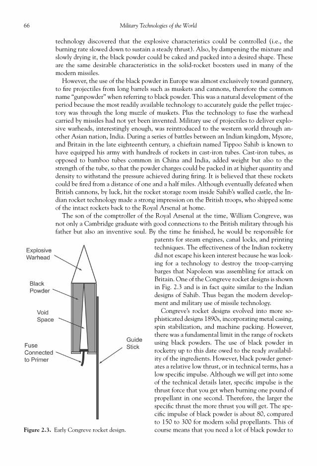
66 Military Technologies of the World
technology discovered that the explosive characteristics could be controlled (i.e., theburning rate slowed down to sustain a steady thrust). Also, by dampening the mixture andslowly drying it, the black powder could be caked and packed into a desired shape. Theseare the same desirable characteristics in the solid-rocket boosters used in many of themodern missiles.
However, the use of the black powder in Europe was almost exclusively toward gunnery,to fi re projectiles from long barrels such as muskets and cannons, therefore the commonname “gunpowder” when referring to black powder. This was a natural development of theperiod because the most readily available technology to accurately guide the pellet trajec-tory was through the long muzzle of muskets. Plus the technology to fuse the warheadcarried by missiles had not yet been invented. Military use of projectiles to deliver explo-sive warheads, interestingly enough, was reintroduced to the western world through an-other Asian nation, India. During a series of battles between an Indian kingdom, Mysore,and Britain in the late eighteenth century, a chieftain named Tippoo Sahib is known tohave equipped his army with hundreds of rockets in cast-iron tubes. Cast-iron tubes, asopposed to bamboo tubes common in China and India, added weight but also to thestrength of the tube, so that the powder charges could be packed in at higher quantity anddensity to withstand the pressure achieved during fi ring. It is believed that these rocketscould be fi red from a distance of one and a half miles. Although eventually defeated whenBritish cannons, by luck, hit the rocket storage room inside Sahib’s walled castle, the In-dian rocket technology made a strong impression on the British troops, who shipped someof the intact rockets back to the Royal Arsenal at home.
The son of the comptroller of the Royal Arsenal at the time, William Congreve, wasnot only a Cambridge graduate with good connections to the British military through hisfather but also an inventive soul. By the time he fi nished, he would be responsible for
patents for steam engines, canal locks, and printingtechniques. The effectiveness of the Indian rocketrydid not escape his keen interest because he was look-ing for a technology to destroy the troop-carryingbarges that Napoleon was assembling for attack onBritain. One of the Congreve rocket designs is shownin Fig. 2.3 and is in fact quite similar to the Indiandesigns of Sahib. Thus began the modern develop-ment and military use of missile technology.
Congreve’s rocket designs evolved into more so-phisticated designs 1890s, incorporating metal casing,spin stabilization, and machine packing. However,there was a fundamental limit in the range of rocketsusing black powders. The use of black powder inrocketry up to this date owed to the ready availabil-ity of the ingredients. However, black powder gener-ates a relative low thrust, or in technical terms, has alow specifi c impulse. Although we will get into someof the technical details later, specifi c impulse is thethrust force that you get when burning one pound ofpropellant in one second. Therefore, the larger thespecifi c thrust the more thrust you will get. The spe-cifi c impulse of black powder is about 80, comparedto 150 to 300 for modern solid propellants. This ofcourse means that you need a lot of black powder toFigure 2.3. Early Congreve rocket design.

67Missile Technology
send the projectile a long distance or to a great height, and a lot of black powder in turnmeans more weight. So without the science and technological foundation, no further ad-vances of black powder rockets were possible.
The basic scientifi c and engineering aspects of rocketry began to be formulated nearthe turn of the nineteenth century. A Russian named Konstantin Edvardovich Tsiol-kovsky with little formal education read and taught himself physics, astronomy, andmathematics while attending public lectures and performing chemical experiments athome. In the midst of these self-absorbed activities, he published what is believed to bethe fi rst rigorous treatise on rocketry in the Scientifi c Review journal in 1903. In it, hepresented logics and detailed calculations for a high-altitude rocket and showed thatblack powder had insuffi cient specifi c impulse for propelling an object, say, to a stableEarth’s orbit or beyond (this would require a velocity of 18,000 mph, according to hiscalculations). Instead, he suggested the use of hydrogen and liquid oxygen, to be pumpedinto a metal combustion chamber. This is remarkable in the sense that he foresaw(through scientifi c calculations) the use of hydrogen as rocket fuel, as used in modernspace shuttles, and also the design of liquid-propellant rocket engines. He also proposedthe use of staging: jettisoning of spent fuel/oxidizer tanks and engines to reduce thesystem weight in fl ight. In spite of his pioneering theoretical contributions, however, hewas a pure theoretician and made no attempt to turn his concepts into an operatingrocket system.
The fi rst realization of the modern rockets was made in the early 1900s by an Americanscientist and engineer, Robert Hutchings Goddard. A physicist by training, Goddard reachedcelebrity status when he published a sixty-nine page treatise called “On a Method of Reach-ing Extreme Altitudes.” This was an age when space travel and rocketry were only fi ctionaltechnologies found in novels by Jules Verne and H.G. Wells, and the public response to re-alizable space travel was sensational, leading in time to the formation of so-called rocketsocieties in the United States, Russia, Germany, and other places. A contemporary of God-dard, Hermann Oberth of Germany, also published pioneering works on rocketry but was notable to achieve the technical breakthroughs foran operational rocket. Goddard shunned public-ity and kept most of his fi ndings in modern rocketdesigns (see Fig. 2.4) within his own operation,consisting of assistants and mechanics; however,he and his ideas were charismatic enough to earnhim continued and large support from public andprivate sponsors such as the Smithsonian Insti-tute, the Carnegie Institute, and Charles Guggen-heim. His work and technical innovations invalves, pumps, controls, and materials culminatedin liquid-propellant rockets that he called the
Figure 2.4. Early designs by the American rocket pioneer, Robert H. Goddard. Photo courtesy of NASA.

68 Military Technologies of the World
“A-series.” The A-series rockets were fueled by gasoline and liquid oxygen and generated200 lbs of thrust for a top speed of 700 mph to reach altitudes up to 7500 feet.
The world’s military powers at the time saw the potential for rockets and started estab-lishing research and development plans. In Russia, it was the Reaction Propulsion Re-search Institute (RNII) under the direction of General Mikhail Tukhachevsky and laterunder an engineer named Segei Korolev when the general was purged and shot on JosefStalin’s orders. In Germany, the resurgent energy and fi nance of the then-Nazi state fundedthe rocket development and test facility at Peenemunde to the tune of $90 million, a tre-mendous amount in 1939. The German army, under the Treaty of Versailles restrictionsfor arms development and production following the World War I, had a free hand in thecase of military rockets because there were no terms or limitations on yet unknown rock-ets. Wernher von Braun and a team of engineers developed advanced pumps for the fueland oxidizers, cooling methods for the combustion chamber, and guidance systems to re-sult in the infamous V-series rockets used during the World War II. So again, the majordriver of the cutting-edge technology was the potential for military use. This indeed wasalso the case in the United States. Following the successes of Goddard’s rockets, the U.S.Army established a research program at the California Institute of Technology (more oftencalled Caltech) to a fl uid mechanic professor named Theodore von Karman. Von Karmanand the Caltech group developed new fuel/oxidizer combinations for both liquid and solidrocket propellants during this time. The specifi c aim of the U.S. Army in use of rocketry wasdirected toward rocket boosters for aircraft, as in jet-assisted take-offs for aircraft. The Caltechgroup eventually formed a corporation called Aerojet, named for the use of rockets.
The developments out of Peenemunde and later Mittelwerk were quite substantial. Theprecursor to the V-2 rocket, called A-4, fl ew to an altitude of 50 miles and a range of 120miles in one of its early test fl ights in October 3, 1942. The fi rst of the V-series weaponsdeployed during the World War II, V-1, however, was actually not a rocket but an un-manned aircraft powered by a gasoline-fueled pulse-jet engine. The V in the V-seriesweapons stood for the German word Vergeltungswaffen , or “weapons of vengeance.” Apulse-jet engine is simply a jet engine with intermittent fuel injection, so that the combus-tion occurs at a frequency from 40 to 150 times per second (as opposed to a continuousoperation). Pulse-jet engines were made without the complexity of compressors typicallyused in standard jet engines and therefore involved simple design and construction. In-stead, the engine relied on so-called ram pressure, pressure that is attained when the air isingested at a high speed. The high frequency of the combustion cycle caused a tremendouslevel of vibration and noise and therefore the nickname “buzz bomb.” V-1s carried close to2000 lbs of explosives. If one saw any photographs of the damage caused by a 1000-lb bombduring the recent Iraq war, one can imagine the physical and psychological horror that2000 lbs of explosives may have caused, particularly in mostly civilian (or random) targetseven after taking into account the change in the energy density of the explosives from thenand now. V-1s were essentially unguided fl ying objects, with the only target control launch-ing them in a certain direction and cutting off the pulse-jet engine, at which time it under-went a free fall to the ground below. V-1s fl ew at a speed of about 390 mph, close to the topspeed of the propeller-powered fi ghter aircraft of the time, so they could be shot down bymanned fi ghters. In fact, out of approximately 7500 V-1s launched toward England,approximately half of them were shot down by fi ghter aircraft and anti-aircraft artillery.
The V-2 was a different beast altogether. V-2s were 46 ft in height, 5 ft 6 in diameter,and carried a warhead of 2000 lbs of explosives. Below the warhead on V-2s was a sectionfor guidance instruments (gyroscopes, steering controls), and a 20-ft section for fuel andoxidizer tanks. The fuel was a mixture of 75 percent alcohol and 25 percent water, whilethe oxidizer was liquid oxygen. The engine section contained the combustion chamber,oxidizer, and fuel pumps and a small steam turbine to drive the oxidizer and fuel pumps.

69Missile Technology
The steam turbine itself used a rocket fuel, hydrogen peroxide. Hydrogen peroxide in itspure state is a highly volatile substance that releases a large amount of heat when it de-composes into water vapor and oxygen. The high-temperature steam thus generated canbe used to drive the steam turbines, which in turn turns the fuel and oxidizer pumps. Theguidance was relatively crude. V-2s were launched at a predetermined angle and direction,and an onboard gyroscope detected a change in the launch angle, direction, and speed.When the gyroscopes detected deviations, then hydraulics were activated for the steeringvanes in the exhaust section for the direction control. The steering vanes worked byslightly altering the direction of the rocket exhaust stream. The speed was controlled sim-ply by shutting off the rocket engine when the set speed was achieved.
V-2s rose to a peak altitude of 50 to 55 miles, and covered a range close to 200 miles.They are what we call ballistic missiles, with a short, high-power boost phase immediatelyafter launch. The boost phase is followed by a free fall trajectory from a high altitudereaching a great speed before impact on the ground. V-2s caused a great deal of physicaland psychological damage during World War II, and they are also signifi cant because theywere precursors to the later American and Russian ballistic missiles.
In addition to the V-2 rockets deployed by the German army, rocket-powered weaponrybegan to take its place as an essential component of the armed forces arsenal during WorldWar II. The U.S. Army bazooka was used against tanks as well as other fortifi ed targets. Thebazooka was essentially a rocket-powered grenade, launched from a cylindrical tube 4.5 ftlong with a 3-indiameter in the version mostly used during World War II. The entire unitwhen loaded was only 13.3 lbs, and the projectile was 3.4 lbs, out of which 1.57 lbs was theexplosive and the remainder mostly the rocket propellant. The rocket booster part derivedfrom Goddard’s pioneering work on rockets, and in fact was a side project of his funded bythe Army Signal Corps during its early development from 1918 to 1923. Later, the designwas knocked into shape by the army and navy engineers and also combined with a shapedcharge (an explosive charge shaped to concentrate the force on a small area for hard targetssuch as tank armor) to become the bazooka, or the rocket launcher M1A1 by 1942. Theearly bazooka model used a 2.36-in diameter tube, but the tube length was 7 ft. However,soon the extra length was discarded in favor of the 3-in diameter tube of 4.5 ft length. Theround was a modifi ed mortar shell with an exhaust nozzle and stabilization fi ns. Instead ofthe mortar propellant pressurizing the launch tube, the addition of the exhaust nozzleforced the explosive gas to be ejected to provide speed for the bazooka rounds. An electri-cal current sent to the primer ignited the main propellant. These bazooka rounds couldknock out medium-armored tanks from 200 yds or be aimed at the tracks and wheels ofheavy-armor tanks, in addition to being very effective against hardened bunkers and build-ing structures. German tanks, wary of bazooka attacks, started sporting vertical armor platesto cover the wheels and tracks. From captured bazookas, the Germans developed their ownversion called panzershreck (tank terror). However, the effective range of 200 yds seemedmuch closer when facing tanks, and also bazooka rounds left a telltale smoke trail thatcould be traced to the bazooka loader and shooter team. The success of the bazooka modelduring World War II led to a continuous evolution of LAW’s (light anti-tank weapons),and follow-up models included the M9, M9A1, M20A1 (the “Super Bazooka”), and mod-ern-day shoulder-fi red SAMs (surface-to-air missiles).
The U.S.-made barrage rockets were another rocket-powered weapon widely used dur-ing World War II. Originally designed as aircraft-fi red air-to-surface missiles, the deploy-ment quickly spread to all branches of the U.S. military. Again, during launch theprojectiles were guided along a tube of about 3 ft in length with a diameter of 3.25 or 4.5in. In contrast to the heavy, complex artillery guns, the rocket-powered bombs could betransported and fi red with much more ease. These rockets were given the M-8 designationby the U.S. military and could be deployed in many different launchers. The 8-tube or

70 Military Technologies of the World
60-tube launchers could be mounted and fi red from the top of trucks or tanks, or a singleM-8 could be launched from something as simple as a plastic tripod. The Navy version wascalled M-16, and these were fi red from a ship-mounted 24-tube launcher called the “Hon-eycomb” or a 60-tube launcher called the “Hornet’s Nest” toward land targets during land-ing operations. These barrage rockets had a range of up to 2 miles with top speeds of 600to 900 mph, depending on the model.
Rocket-fi red weapons, bigger and more powerful by this time, started to augment thetypical cannon and dropped-bomb armament in aircraft. The British developed the so-called RP (rocket projectile) that was fi n-stabilized and propelled by solid propellant in a3-in diameter tube, to carry a 65 lb explosive in a 5-in diameter warhead. The Americancounterpart of this air-launched direct-fi re weapon was the FFAR (forward fi ring aircraftrocket) that was used on slow or stationary surface targets. An upgrade version calledHVAR (high velocity aircraft rocket) was 6 ft long and could penetrate 1.5 in of steelarmor by impacting the target at a speed of 950 mph. Another aircraft-launched rocketcalled “Tiny Tim” was not tiny at all with a 12-in diameter and 1200 lbs of weight, out ofwhich 500 lbs was armor-piercing warhead designed for use against Japanese warships.
After World War II, the use of the rockets expanded to non-military uses in high-altituderesearch, high-speed aircraft developments, and various space programs. All of these ap-plications would, however, be intertwined in one form or another with military exploita-tions, such as in large rocket thrusters being converted for launching of nuclear weaponsor satellites being used as reconnaissance platforms. Similarly, development of high-speedaircraft capable of breaking the sound barrier was pursued by the U.S. Army, Navy, AirForce, and NACA (National Advisory Committee on Aeronautics). The aircraft de-signed to pursue this interest in high-speed fl ight was the famed X-1, built by Bell Aircraftand powered by a four-chamber alcohol-oxygen rocket engine. Unlike other airplanes of
the time (see Figs. 2.5 and 2.6), X-1 was shapedmore like a bullet with a thin, fl at wing and ahorizontal tail that rotated in its entirety muchlike modern jet fi ghters. The liquid-propellantrocket motor could not be throttled, instead thepilot ignited a combination of four chambers inturn to apply some control over the total thrust.X-1 carried just enough fuel to propel itself forshort durations, so it was carried underneath aB-29 bomber and released at high altitudes tobegin its fl ights. On October 14, 1947, four daysafter reaching Mach 0.997, X-1 fl own by test pilotCaptain Charles “Chuck” Yeager was releasedfrom the B-29 bomber at an altitude of 20,000 ft.Igniting two of the rocket combustion chambersquickly accelerated the aircraft to an altitude of40,000 ft. Igniting the third chamber at that alti-tude pushed the Mach number to 1.02 and then1.06. Eventually, X-1 would reach a speed ofMach 1.45, and because the engine did not re-quire any external air an altitude of 70,000 ftcould be reached by the rocket aircraft.
The German V-2 rockets were the fi rst ballis-tic missiles used for military purposes, and therocket technology was quickly acquired by both
Figure 2.5. X-1 rocket-powered aircraft that fi rstbroke the sound barrier. Photo courtesy of the U.S.Air Force.

71Missile Technology
the United States and the Soviet Union after the downfall of the Nazi Germany. Up to1950, the United States Army working with the Jet Propulsion Laboratory at Caltechused the V-2 as the primary booster for sounding rockets, high-altitude vehicles withvarious sensors to measure properties of the upper atmosphere. The V-2 rocket was com-bined with a smaller WAC Corporal upper-stage rocket and fl ew to a record 250-milealtitude in the fi rst operational fl ights of multistage rockets. The U.S. Navy in collabora-tion with the Applied Physics Laboratory of Johns Hopkins University developed its ownsounding rocket called “Aerobee,” capable of lifting 150-lb payloads to an altitude of 60miles. The Viking rocket design followed with a number of innovations. A more accurateguidance algorithm was put in place, light aluminum material was used in place of steelfor major structural components, the fuel tank served as the outer rocket casing, andengines were mounted on gimbals to swivel back and forth for trajectory control in placeof troublesome carbon vanes that defl ected the rocket exhaust streams. The fi nal versionsof Viking rockets would be capable of sending 825 lbs of instrumentation to a height of158 miles.
The Russians also used the German V-2 rockets as the starting point of their rocketprogram. From the R-1 (SS-1 Scud by the western or later NATO designation) to R-5(SS-3 Shyster), these rockets were direct adaptations of the V-2 rocket engine technol-ogy, although improvements in the engine design and propellant formulation increasedthe fi nal range to 700 miles and the payload to 3000 lbs. The upgraded version of R-5,designated R-5M, would also contain an improved guidance unit to be able to hit targetswithin a radius of about 1000 ft, whereas the V-2 was merely sent toward city-sized tar-gets. The American counterpart of the V-2 adaptation rocket called the “Redstone” was
Figure 2.6. X-1 aircraft attached under B-29 bomber. Photo courtesy of the U.S. Air Force.

72 Military Technologies of the World
developed by Wernher von Braun himself working with other German expatriates fromPeenemunde and had similar accuracy except with a range similar to the original V-2(200 miles). With such accuracy and a payload of several thousand pounds, these servedas the fi rst potential carriers of nuclear warheads for both countries. To achieve thislevel of accuracy, an inertial guidance system was used in conjunction with gimbaledengines. The inertial guidance system contained accelerometers and gyroscopes to de-tect the changes in the speed and orientation of the rocket, and by keeping track ofthese changes the guidance algorithm computed the deviation from the intended trajec-tory. Compensations were made by turning the engine gimbals to bring the rocket backto its intended line of motion. In addition, a separable warhead was designed to follow astabilized motion away from the bulky booster during the approach phase. The SovietR-5M was armed with a 1 MT (megaton or million tons) warhead, while the AmericanRedstone was capable of delivering a 3.5 MT weapon. To give an idea as to the quantumleap in the destructive power of these weapons, the atom bomb dropped on Hiroshimawas 15 kT (kiloton or thousand tons) and the largest conventional bomb used duringWorld War II, called “Grand Slam,” was 5 tons in equivalent TNT. Although the rangeof the missiles at this time was measured in hundreds of miles, not yet a threat as long-range ballistic missiles, these technologies would allow future missiles to become inter-continental carriers of nuclear warheads once boosters were developed to increase therange to thousands of miles.
The next-generation rockets would indeed bring both the payload and range close tothe ICBM category. Using kerosene and liquid oxygen (LOX) in high-pressure combus-tion chambers enhanced the thrust of the American “Thor” and “Jupiter” to give a rangeof 1400 and 1600 miles, respectively. The Russians opted for the use of nitric acid as theoxidizer, under the calculated risk that even though nitric acid was highly corrosive it didnot need cryogenic equipment as LOX did and therefore could be kept in a ready-to-launch state for much longer periods of time. The Soviet R-12 and R-14 had respectiveranges of 1400 and 2000 miles, and this class of missiles was referred to as “theater weap-ons” or IRBMs (intermediate-range ballistic missiles). Due to their intermediate range,they needed to be based relatively close to the targets. For the American IRBMs, Italy andTurkey served as suffi ciently close launch points, while the Soviets did not possess suchlogistic launch sites except for newly reformulated Cuba under Fidel Castro. The clandes-tine operation to base Soviet R-12s and R-14s was discovered by the American reconnais-sance airplanes and led to the Cuban missile crisis in 1962. The ensuing confrontation wasquite tenuous for about two weeks until the two sides made a covert agreement to pulltheir respective missiles from Cuba for the Soviets and from Italy and Turkey for theAmericans. In the next several years, both sides would develop operational long-rangeICBMs, obviating the need for such close-range launch sites altogether.
In fact, the work to develop rocket boosters capable of carrying heavier payloads overlonger ranges was already underway in the late 1950s. The Soviet R-7 and R-7A, forexample, had a range of up to 5000 miles with a payload of 12,000 lbs. On top of that, animproved guidance system using both inertial and radio control improved the accuracy aswell. The R-7 rockets had a core booster surround by four additional boosters, and eachbooster had four small rocket engines for a total of twenty engines. There were separatesmall gimbaled vernier engines installed in the core booster for attitude control, whilethere were two such vernier engines on each side booster. The fi rst ICBMs developed inthe United States were the Atlas and Titan (Fig. 2.7), introduced in 1961 and 1962, re-spectively. The Atlas missiles were equipped with one main sustainer and two boosters,where the boosters were jettisoned after the main boost phase. The Titan had a moreconventional two-stage design and could carry a larger payload than Atlas. Both of thesemissiles contained inertial guidance and separable reentry vehicle design to give a 600-yd

73Missile Technology
radius of accuracy in delivery of 1 MT–class thermonuclear warheads. These rocketboosters would also serve both nations wellin their respective space programs, withthe R-7 booster being used to place thefi rst artifi cial satellite, Sputnik I, in orbit. TheAmerican manned space fl ight programsMercury and Gemini used the Redstone,Atlas (shown in Fig. 2.8), and Titan II mis-siles in the 1960s. The Titan series evolvedfrom a 30-m long RP-1/LOX fueled Titan I
Figure 2.7. The early version of the Titan booster used forthe Gemini manned space fl ights. Photo courtesy of theU.S. Air Force.
Figure 2.8. Atlas V launch vehicle evolved from the USAFICBM program in the 1960s. Photo courtesy of the U.S. AirForce.

74 Military Technologies of the World
booster, to Titan II ICBMs, to TitanIII with two side solid rocket boost-ers, to the Titan IV Centaur whosecombined length with all of its IUS(Inertial Upper Stage) componentsin place was close to 50 m. The use ofLOX in Titan I meant that this cryo-genic oxidizer needed to be pumpedinto the tank prior to launch, and thissequence would take fi fteen to twentyminutes, diminishing its launch read-iness capability. For this reason, TitanII and later versions would use hydra-zine-based fuel with nitrogen tetrox-ide as oxidizer. The Titan IV couldcarry payloads equivalent in size andweight to those that could be deliv-ered by the space shuttles and hasbeen the most powerful booster forunmanned payloads for the UnitedStates. The launch was made withonly the side solid boosters running,and the fi rst-stage liquid propellantcore engine fi red up after two min-utes of the solid rocket burning. TheTitan IV liquid-propellant motors useAerozine 50 as fuel and nitrogen tet-roxide as oxidizer, which like nitricacid requires elaborate and expensivehandling equipment. The use of thecorrosive and hypergolic (ignitable
on contact) substances again bypasses the need for the cryogenic equipment required forLOX and allows storage of the propellants for extended periods of time. The fi rst andsecond stage engines burn from 164 and 223 s, respectively, while the third Centaur statehas a burntime of 625 s. For low earth orbits (LEO), payloads of up to 47,800 lbs (lowerfor polar LEO) can be launched using Titan IV, while for higher-altitude geosynchronousorbits or interplanetary trajectories the limiting weight is approximately 12,500 lbs. Theearly Titan rocket fuel RP-1 is highly refi ned kerosene, while the Aerozine 50 used inTitan IV is a 50/50 mixture of hydrazine and UDMN (unsymmetrical dimethylhydra-zine). The Titan III/Centaur combination would also be known for its role in sending theViking Mars probe and Voyager probe to the outer planets and the Helios solar probe.
The emergence of spy satellite technology accelerated the pace of development and useof dedicated launch vehicles. The IRBM booster Thor was coupled with an upper stage“Agena” to launch a series of “Corona” spy satellites. The Thor-based multistage boostersevolved into NASA’s Delta rockets that could be augmented with strap-on boosters toprovide heavy payload and high altitude capabilities. Figure 2.10 shows the evolution ofthe Delta rocket from the lone Thor IRBM, to the Thor-Able combination with the Ableupper stage added on top of Thor, to a Delta II with multiple side strap-on solid-propellantrockets, and to Delta IV with the core plus two liquid-propellant strap-on boosters.The Delta II and IV launch vehicles are used up as of the time of this book’s publication
Figure 2.9. The Titan IV Centaur booster used for sending un-manned payload into earth orbit by the USAF. Photo courtesy ofthe U.S. Air Force.

75Missile Technology
(see Fig. 2.11), and during 1980s, after the Challenger disaster and the stand-down of thespace shuttle fl eet, they served as able launch vehicles to uplift the backlog of orbitalpayloads.
MODERN MISSILE TECHNOLOGY
The use of missiles has multiplied to all branches of the military. Below are some of theweapon categories in which missiles are specifi cally deployed:
Air-to-air missile (AAM) Air-to-surface missile (ASM) Surface-to-air missile (SAM) Surface-to-surface missile (SSM) Ballistic missile (BM)
Intercontinental ballistic missile (ICBM) Submarine launched ballistic missile (SLBM) Anti-ballistic missile (ABM)
Cruise missile Anti-ship missile (AShM) Anti-submarine Rocket (ASROC) Anti-tank guided missile (ATGM) Anti-satellite weapon (ASAT) Anti-radiation missile (ARM)
Air-to-Air Missiles
These missiles are typically fi red from aircrafts or helicopters against other airborne tar-gets. For some long-range air-to-air missiles (AAMs), the missile is sent to the coordinatewhere the target aircraft has been identifi ed through an inertial guidance system, then amore precise guidance using radar or infrared (heat seekers) tracking may be applied to zeroin on the target. Short-range AAMs may be equipped with a simple, multiwavelength infra-red seeker to lock on to the exhaust of jet aircrafts.
Figure 2.10. A sequence of images showing the evolution of the Delta rocket. Photos courtesy of the U.S. AirForce and NASA.

76 Military Technologies of the World
Table 2.1 shows the various AAMs used by various military forces in the world. Asshown in the table, many of the AAMs are guided by a passive, infrared (IR) trackingsystem due to its compactness and simplicity. These infrared seekers detect the thermalexhaust from jet engines and guide the missile in the direction where the maximum infra-red signal is detected. Heat from the exhaust is partially given off through infrared radia-tion that can be detected using infrared detectors. Active radar tracking requires themissile to carry a small-aperture radar antenna and send out radar signals to seek the targetaircraft. These self-guidance methods are associated with the fi re-and-forget missiles andcan be used for medium- to long-range targets. Semi-active radar means that the missileonly carries the radar receiver and homes in on the radar signal sent from the launch air-craft and refl ected off from the target aircraft. Semi-active radars require the launch air-craft to remain engaged and lock its radar on the target. Although rarely used in AAM,sometimes optical tracking or “beam-riding” guidance systems are used. Instead of radarlocks, the launch aircraft illuminates the target with a laser beam the refl ection of whichis acquired by the missile homing device. We will look at the technology behind differentguidance systems in more detail in a separate section later in this book.
A photograph of AIM-120 AMRAAM, also known as the Slammer by the fi ghter pi-lots, is shown in Fig. 2.12. The missile is long and thin, contained in a 7-in diameter tubewith a length of 12 ft. About half the length of the missile is used for the solid propellant,and the nozzle is movable to provide rapid control of the missile heading. An igniter wireruns through the center of the propellant and is fi red up at missile launch. A data link isalso located at the tail of the missile. A highly effective warhead of less than 50 lbs is lo-cated in the mid-section, just ahead of the fi xed middle fi ns. A target detector device(TDD) and fuse are located next to the explosive charge, and when TDD senses the
Figure 2.11. Launch of the Delta rocket with an unknown National Reconnaissance Offi ce payload fromVandenberg Air Force Base. Photo courtesy of the U.S. Air Force.

77Missile Technology
Table 2.1. Some of the Main AAMs in the World.
Country of Origin Name Guidance Method
Brazil Mectron MAA-1 Piranha Short range IRFrance Matra R550 Magic, similar to the
American AIM-9 SidewinderMatra Magic IIMagic Super 530F/Super 530D, French
counterpart of the AIM-7 SparrowMBDA MICA—French counterpart of
the AIM-120 AMRAAM
IRIRActive radarInertial guidance and active
radar (fi re-and-forget)
Italy Alenia Aspide, Italian manufacturedversion of the AIM-7 Sparrow
MBDA MeteorIRIS-T, replacement for AIM-9
Sidewinder
Active radarMedium-range, active radar
homingShort-range infrared
homingIsrael Rafael Python 4—medium range IR
Rafael Python 5, improves on Python 4Medium-range IRMedium-range IR
People’s Republicof China
PL-1, Chinese version of the SovietKaliningrad K-5 (NATO reportingname AA-1 “Alkali”) PL-9
PL-10, Chinese version of the ItalianAspide
PL-11/AMR-1, similar to the Russian Vympel R-27 (NATO reporting nameAA-10 “Alamo”)
SD-10TY-90, fi rst air-to-air missile designed for
helicopters
Short-range IRShort-range IRSemi-active radarActive homing guidance
systemMedium-range active radar
Russia Kaliningrad K-5 (NATO reportingname AA-1 “Alkali”)
Vympel K-13 (NATO reporting nameAA-2 “Atoll”)
Kaliningrad K-8 (NATO reportingname AA-3 “Anab”)
Raduga K-9 (NATO reportingname AA-4 “Awl”)
Bisnovat R-4 (NATO reportingname AA-5 “Ash”)
Bisnovat R-40 (NATO reportingname AA-6 “Acrid”)
Vympel R-23 (NATO reportingname AA-7 “Apex”)
Molniya R-60 (NATO reportingname AA-8 “Aphid”)
Vympel R-33 (NATO reportingname AA-9 “Amos”)
Vympel R-27 (NATO reportingname AA-10 ”Alamo”)
Vympel R-73 (NATO reportingname AA-11 “Archer”)
Vympel R-77 (NATO reportingname AA-12 “Adder”)
Beam TrackingShort-range IRIRIRIRLong-range IRMedium-range SARH or IRShort-range IRLong-range active radarMedium-range SARH or IRShort-range IRMedium-range active radar
(Continued)

78 Military Technologies of the World
proximity to the target it sends a signal through thefuse to detonate the warhead. The remaining forwardsection contains the radome for the active radar, bat-tery, transmitter, and main guidance electronics. Itssolid rocket motor propels the missile to supersonicspeeds and for directional control uses vectoredthrust and moving fi ns. As previously noted, it usesan inertial guidance system to get to the target vicin-ity and then turns on its active radar to home in onthe target. Its unit cost is in excess of $386,000 as of2003, and it is manufactured by Hughes/Raytheon. Itis an improved AAM over the preceding AIM-7Sparrow, envisioned as the beyond-visual-rangeweapon, and has a more advanced and lethal guid-ance system. AIM-7 missile guidance was via semi-
active radar, as listed in Table 2.1, meaning that the aircraft must illuminate the targetwhile AIM-7 can only guide itself based on the refl ection of this radar signal from thetarget. This requires the aircraft to be fully engaged during the missile pursuit. In contrast,AIM-120 is installed with active radar, a radar transmitter antenna, and a pulse seeker.The pulse seeker searches for a specifi c waveform radar signal sent out by the transmitterto overcome interference, jamming, and other electronic countermeasures. This autono-mous tracking allows the aircraft to pursue multiple targets and disengage after the missilelaunch. The active radar is activated on missile’s arrival at the scene, and an inertial guid-ance unit with data update capabilities via signals sent by the launch aircraft takes themissile to the engagement scene. Also, the armament carried by AIM-120 is an improve-ment over AIM-7. AIM-120 carries a blast-fragmentation warhead with a proximity fuse,to enhance its kill probability.
AIM-120s are powered by the Hercules solid-propellant rocket motor. The ingredientsof the solid propellant are not only proprietary but also classifi ed, but they are designed forsustained high thrust and reduced smoke (to make visible detection diffi cult). The rocketmotor propels the missile to a speed of approximately Mach 4 (four times the speed ofsound at that altitude), and a maximum range of 46 miles. AMRAAM is compatible withmost United States and NATO fi ghter aircraft, including the F-15, F-16, F-18A, F-22, and
Table 2.1. Continued
Country of Origin Name Guidance Method
Brazil Mectron MAA-1 Piranha Short range IRUnited Kingdom AIM-132 ASRAAM
Skyfl ashShort-range, IRRadar
United States AIM-4 FalconAIM-7 SparrowAIM-9 SidewinderAIM-54 PhoenixAIM-120 AMRAAM
Radar/IRMedium-range semi-active radarShort-range IRShort-range IRLong-range, semi-active and
active radarMedium-range, active radar;
replaces AIM-7 Sparrow
Figure 2.12. AIM-120 AMRAAM unleashedfrom an F-16 fi ghter jet. Photo courtesy of theU.S. Air Force.

79Missile Technology
British Sea Harrier. AMRAAMs can alsobe used as surface-launched CLAWS (com-plimentary low altitude weapon system)carried on HMMWV (Humvee) vehicles.Five AMRAAMs can be adapted for Hum-vee launch in the HUMRAAM adaptationprogram to provide mobile air defense.
AIM-54 Phoenix (Fig. 2.13) is anotherfi re-and-forget type of missile, except witha much bigger range. It has an active radarguidance system and a maximum range of127 miles at a speed of Mach 5. Most jetfi ghters have maximum cruise speed (without fi ring the afterburner) of just over Mach 1and maximum speeds between Mach 2 and 3. For example, the U.S. Navy’s F-14 Tomcat,which carries Phoenix missiles, has a maximum speed of Mach 2.34. At an altitude of49,000 ft, Mach 2.34 is 1544 mph. So a missile speeding at Mach 5 toward a much slowerjet fi ghter is a formidable threat. However, both AIM-54 and F-14 Tomcats have beenretired from the United States Navy. A photograph of a Phoenix missile shows the sizethat was needed to carry suffi cient propellant for the required speed and range. The long-burning Mk47 solid-propellant rocket motor was made by Rocketdyne and, along with thehydraulically driven tail fi ns, provided exceptional sustained thrust and maneuverability.The front section contained the radome for the planar array active radar and guidanceelectronics, and again the warhead of 60 kg of high explosive is found in the mid-section.Three proximity fuse antennas embedded equidistantly on the outside of the missile sensesthe presence of the target along with an impact sensor in the event of a direct hit. To therear of the missile sits the solid propellant motor, and the rear section contains the hydrau-lic control for the tail fi ns. The last version of the Phoenix missile, AIM-54C weighed over1000 lbs at a length of 13 ft and diameter of 15 in (the wingspan was 3 ft). The F-14 Tom-cat carried up to six of these Phoenix missiles. A weapon control system interfaced withthe onboard Phoenix missiles assigned individual target coordinates for each and launchedthem in a sequence as determined by the target priority or as input by the pilot.
The AIM-9 Sidewinders (shown in Fig. 2.14) are smaller, yet effective anti-aircraft mis-siles carried by the United States and many other of the world’s jet fi ghters in variousversions. The original design was made by the Naval Weapons Center (now Naval AirWarfare Center Weapons Division) at China Lake, California, but the production is nowshared between Ford Aerospace and Raytheon. This is one of the most effective AAM inexistence in terms of performance, size, and cost, and nearly all U.S. allies with a respect-able air force use the Sidewinders. The simplicity in the design, with less than twenty-fourmoving parts in the early version, allowed low-cost production, reliable performance underrugged environments, and easy adaptation to a multitude of aircraft. The design goes as farback as 1949, to the days of vacuum tubes in electronic components, but a small team ofengineers succeeded in designing an operation-passive infrared seeker head that would fi tin the 5-in diameter body of the Sidewinder. Since then, advances in solid-state electron-ics have allowed much better sensor and guidance to be installed in the missile. The earlyversions of the missile performed erratically except in close range where the infrared sig-nature was unmistakable, but the uncooled lead sulfi de (PbS) infrared sensor had diffi cultyin low visibility conditions (cloud, rain, etc.) and also had a tendency to lock on the sunor refl ections of the sun on lake or river surfaces in clear weather. However, by versionAIM-9D nitrogen-cooled magnesium fl uoride sensors permitted higher infrared sensitivityin inclement weather conditions, and the narrowed fi eld of view also minimized false
Figure 2.13. AIM-54 Phoenix missile. Photo courtesy of theU.S. Department of Defense.

80 Military Technologies of the World
lock-on problem. Subsequent versions proved to be highly successful based on this design,but modifi cations continued on the guidance unit to further enhance the missile’s lock-oncapabilities from longer range. In the later versions the IR sensor operates in two wave-lengths to seek corroborating signals to defeat fl ares or other countermeasures. Increasedtracking speed along larger fi ns moved by high-power actuators improved the hit ratio,while annular blast fragmentation ensured signifi cant damage at contact. Due to its rela-tively small size, the Sidewinders are used for short-range targets and carry 25 lbs of blastfragmentation warhead, again with a proximity fuse. A separate optical target detectorsenses the presence of target in its potential kill radius and detonates the armament send-ing the high-impact fragments for either kill or severe damage. The current version,AIM-9X, encompasses design changes to place the missile to the forefront of short-rangemissile performance in comparison with similar missiles used by other nations. An infraredimaging sensor, higher tracking speed, better seeker signal processing and tracking algo-rithm, and more powerful warhead are considered essential components in the next-generation short-range AAMs.
The AIM-132 ASRAAM (advanced short-range air-to-air missile) represents a moderndesign from scratch. The British government invested close to $1 billion in its developmentin the late 1990s in an effort to counter the threat posed by the Russian Vympel R-73(NATO reporting name AA-11 “Archer”) missile with its large sensor fi eld of view for off-axis target acquisition, acquisition range, and tracking ability. The target acquisition charac-teristics were signifi cantly improved using the Raytheon-Hughes sapphire-domed infraredfocal plane imaging sensor with a 128 × 128 pixel array. By not only registering the magnitudeof the selected infrared wavelength signatures but also the shape and direction of the signal,the target identifi cation is enhanced along with counter-countermeasure capability. Its speedof above Mach 3 also places the ASRAAM a step ahead of the Sidewinder and the Archer.
Figure 2.14. A photograph showing the relative size of the AIM-9 Sidewinder (top row) and AIM-7 Sparrow(bottom) missiles. Photo courtesy of the U.S. Air Force.

81Missile Technology
Russia possesses highly effective AAMs in the Archer, a schematic of which is shown inFig. 2.15. Although placed in a 170-mm-diameter, 2.9-m-long body, its range is rated at 30km for R-73A and up to 40 km in later versions. AA-11 is carried by a fl eet of modernRussian fi ghters including the MiG-29, Su-27, Su-32, and Su-35, as well as some of theolder Russian jets. The missile guidance when coupled with the pilot’s helmet input canbe set to lock on targets in a +/– degree lateral directions from the aircraft axis, and withhigh maneuverability it can pursue a variety of airborne targets, fi ghters, bombers, attackaircrafts, helicopters, and cruise missiles, even undertaking high-G evasive maneuvers witha 12-G turn capability of its own. With exceptional counter-countermeasure and anti-jam-ming algorithms, it is a short-range fi re-and-forget type of weapon in spite of the passivenature of the sensor device. Unlike the western counterparts with tail aerodynamic control,R-73 employs the forward surface control, or canards. The combination of the fi xed forwardstabilizer and control canards provide outstanding maneuverability. As shown in the sche-matic a laser optical sensor sends out a laser beam to look for refl ected signals from the air-craft, which would set off the detonation fuse if the signal is above the set threshold. Aminiature radar proximity sensor is also available, along with the standard impact sensor. A7.4-kg high-explosive expanding rod warhead serves as the armament for the missile.
The stated ranges of the air-to-air missiles above are typically given for optimal condi-tions, such as head-on target pursuit and high altitudes where the air density is low andtherefore the drag force on the missile is also small. For head-on targets, the distance be-tween the target and missile rapidly closes due to the motion of the missile and the target.For tail chases, the missile obviously needs to cover much more range to acquire the target.Thus, the operating range of AAM decreases dramatically for hard pursuits involving steepturns, tail chase, and climbs and also at low altitudes. For example, the range of the RussianVympel R-77 is stated to be 100 km for head-on targets, but this is known to decrease to
Figure 2.15. A detailed schematic of the Russian short-range AAM, Vympel R-73 (NATO reporting nameAA-11 “Archer”). Schematic from the U.S. Department of Defense

82 Military Technologies of the World
only 25 km for hard pursuits. Even on head-on targets, the same missile only can fl y in a 20km range at sea level.
The Vympel R-77 (AA-12 Adder or unoffi cially “AMRAAMski”) is the Russian coun-terpart to the AIM-120 AMRAAM medium-range missile. In addition to an accurateguidance unit, R-77 has an exceptional range of 90 km in the solid-rocket version and 175km in the ramjet-powered R-77M1 version. The ramjet version is also powered initially bya small solid-propellant booster until the ramjet can start running at supersonic speeds. Forthe pure solid-rocket version R-77, the speed tops over Mach 4, and it can operate at analtitude of 25 km. Some versions of R-77 are suspected of high-altitude capability to thetune of 120 to 160 km, perhaps as a possible anti-satellite or anti-missile weapon. Similarto AMRAAM, an inertial guidance system sends the missile to the target area aided bymid-course adjustments, and then the active radar homes in on the intended target. Aterminal infrared seeker is also available, as modern imaging sensors offer highly reliableshort-range target lock-on capabilities.
Missile Guidance
We saw that IR (infrared) guidance is widely used for short-range AAMs. For missileswith longer ranges, more sophisticated active or semi-active radars are installed. In gen-eral, however, there are many different methods that are available to guide the missilesonto the target. The following are the various missile guidance methods.
1. Command-guidance A. Manual command line-of-sight (MCLOS) B. Semi-automatic command line-of-sight (SACLOS)
2. Beam-riding guidance3. Radar
A. Active radarB. Semi-active radarC. Track-via-missile (TVM)
4. Infrared guidance5. Inertial and GPS guidance6. Terrain contour matching (TERCOM)/Digital scene-matching area correlator
(DSMAC)7. Targeting by image contrast
Regardless of the guidance method, the missile guidance system consists of the follow-ing components. The sensor sends and/or receives radar, infrared, or other signals to trackthe target. The sensor unit typically includes a signal processing device to extract the truetarget signal in the midst of interference and noise. The signal is then fed to the onboardelectronic hardware to generate commands according to sophisticated guidance laws. Theonboard electronics involve a hardwired microcomputer (essentially a set of computerchips) dedicated to this kind of calculations. Electronically generated commands are thensent to the control unit, which activates various target adjustment devices, such as fi ns,tails or thrust vectoring. This loop is continuously operated, although as we shall see in thefollowing discussions various guidance methods may be switched from one to the otherdepending on the fl ight phase of the missile.
The fl ight of the missile consists of the boost, mid-course, and terminal phases. The boostphase launches the missile away from the launcher, and no guidance is activated. Some long-range missiles may have a separate boost-phase rocket motor, to be jettisoned after they reach
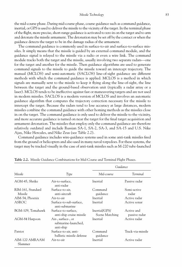
83Missile Technology
the mid-course phase. During mid-course phase, course guidance such as command guidance,inertial, or GPS is used to deliver the missile to the vicinity of the target. In the terminal phaseof the fl ight, more precise, short-range guidance is activated to zero in on the target and to armand detonate the missile armament. The detonation may be set off by the contact or when theguidance detects the target to be in the damage radius of the armament.
The command guidance is commonly used in surface-to-air and surface-to-surface mis-siles. It simply means that the missile is guided by an external command module, and theguidance signal is relayed to the missile via a radio or even a wire link. The commandmodule tracks both the target and the missile, usually involving two separate radars—onefor the target and another for the missile. Then guidance algorithms are used to generatecommand signals to the missile to guide the missile toward an intercept trajectory. Themanual (MCLOS) and semi-automatic (SACLOS) line-of-sight guidance are differentmethods with which the command guidance is applied. MCLOS is a method in whichsignals are manually sent to the missile to keep it fl ying along the line-of-sight, the linebetween the target and the ground-based observation unit (typically a radar array or alaser). MCLOS tends to be ineffective against fast or maneuvering targets and are not usedin modern missiles. SACLOS is a modern version of MCLOS and involves an automaticguidance algorithm that computes the trajectory correction necessary for the missile tointercept the target. Because the radars tend to lose accuracy at large distances, modernmissiles combine the command guidance with other homing methods as the missiles closein on the target. The command guidance is only used to deliver the missile to the vicinity,and more accurate guidance is turned on near the target for the fi nal target acquisition andarmament detonation. The missiles that employ only the command guidance are thereforerelatively outdated and include Russian SA-1, SA-2, SA-3, and SA-15 and U.S. NikeAjax, Nike Hercules, and Nike Zeus (see Table 2.2).
Command guidance includes wire-guidance systems used in some anti-tank missiles fi redfrom the ground or helicopters and also used in many naval torpedoes. For these systems, thetarget may be tracked visually in the case of anti-tank missiles such as M-220 tube-launched
Table 2.2. Missile Guidance Combinations for Mid-Course and Terminal Flight Phases.
Guidance
Missile Type Mid-course Terminal
AGM-45, Shrike Air-to-surface,anti-radar
Inertial Passive radar
RIM-161, StandardMissile
Surface-to-air,anti-aircraft
Commandguidance
Semi-activeradar
AIM-54, Phoenix Air-to-air Inertial Active radarASROC Surface-to-sub-surface,
anti-submarineInertial Active sonar
BGM-109, Tomahawk Surface-to-surface,anti-ship cruise missile
Inertial/GPS/Scene Matching
Active andpassive radar
AGM-84 Harpoon Air-, surface-, orsubmarine-launched,anti-ship
Inertial Active radar
Patriot Surface-to-air, anti-ballistic missile defense
Commandguidance
Track-via-missile
AIM-120 AMRAAMSlammer
Air-to-air Inertial Active radar
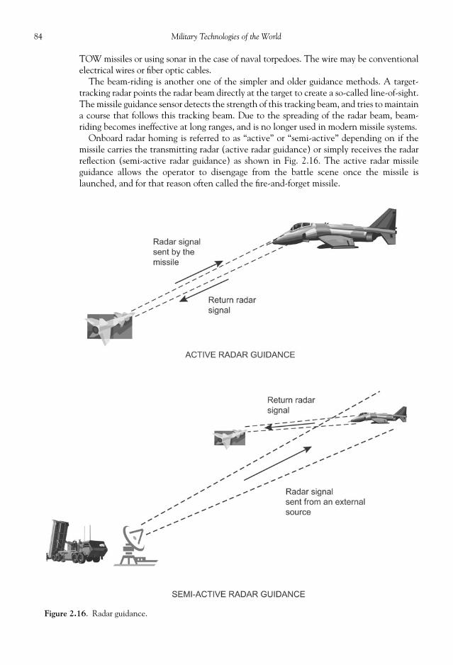
84 Military Technologies of the World
TOW missiles or using sonar in the case of naval torpedoes. The wire may be conventionalelectrical wires or fi ber optic cables.
The beam-riding is another one of the simpler and older guidance methods. A target-tracking radar points the radar beam directly at the target to create a so-called line-of-sight.The missile guidance sensor detects the strength of this tracking beam, and tries to maintaina course that follows this tracking beam. Due to the spreading of the radar beam, beam-riding becomes ineffective at long ranges, and is no longer used in modern missile systems.
Onboard radar homing is referred to as “active” or “semi-active” depending on if themissile carries the transmitting radar (active radar guidance) or simply receives the radarrefl ection (semi-active radar guidance) as shown in Fig. 2.16. The active radar missileguidance allows the operator to disengage from the battle scene once the missile islaunched, and for that reason often called the fi re-and-forget missile.
Figure 2.16. Radar guidance.

85Missile Technology
Track-via-missile (TVM) is a form of semi-active radar guidance used in the Patriotmissile system. An external radar illuminates the target, and the refl ected radar signal isintercepted by a radar receiver onboard the missile. However, unlike the conventionalsemi-active systems TVM requires one additional step of downloading the received radarsignal to the ground-based control station where the necessary trajectory corrections arecomputed and then uploaded back to the missile, all using high-speed communicationlinks. The complexity of the TVM requires fast communication links that are viable onlyin short-range operations. However, the advantage of TVM is that most of the heavy andexpensive electronics are not onboard the missile.
Infrared guidance is a passive method, where there are no onboard transmitters of anykind. Instead, infrared radiation or heat generated by the aircraft jet engines or other hotsurfaces are identifi ed by either point or imaging sensors. All objects at a given tempera-ture emit characteristic radiation, one of the examples being the sun radiating from thesolar surface temperature of about 6000 o C or about 11,000 o F. Objects at lower tempera-tures radiate much less energy and at progressively longer wavelength. In addition to thisthermal radiation, jet exhaust contains lots of carbon dioxide and water vapor, which alsoemit in the infrared range at high temperatures (1500 to 4000 o F, depending on whetherthe afterburner is on or not). Carbon dioxide, for example, has a bright emission band atthe 4.2 micron wavelength, which can be picked up be infrared sensors using materialssuch as lead sulfi de (PbS), indium antimonide (InSb), and mercury-cadmium telluride(HgCdTe). These are the same materials used in night vision or thermal imaging sensors.Cooling these infrared detectors to low temperatures further increases their sensitivity byreducing sensor thermal noise, and liquid-nitrogen, thermoelectric, or other cooling meth-ods are applied to keep these detectors at sub-freezing temperatures. Modern IR seekers useinfrared imaging to scan a large area in the forward direction of the missile, which is es-sentially taking infrared camera shots of the air space in front and logging the directionfrom which the infrared signal originated from. Also, instead of looking at a single infraredemission band, modern heat-seekers may look for duplicating infrared signals at two wave-lengths to discern the target from fl ares or other countermeasures. The IR seeker missilesthus have windowed domes at the nose that house gimbaled IR cameras of up to 4 mega-pixel resolutions. The dome itself must be transparent to the infrared (glass is not) and alsobe able to withstand the high temperatures encountered when the missile fl ies at Mach 2to 3, similar to space vehicles heating up during high-speed reentry into the atmosphere.The gimbal system rotates the optical components to cover large scan angles and alsostabilizes against any vibration to minimize the target image jitters.
For stationary targets or targets whose location is identifi ed, missiles can be sent to spe-cifi c locations using inertial guidance or GPS devices. Inertial guidance systems track theacceleration of the missiles using a set of gyroscopes and accelerometers. Accelerometersare devices that measure how fast the speed is changing with time. The data from the ac-celerometers can be integrated to give a time history of the missile speed, and that in turngives the distance covered by the missile from the launch location. For keeping track ofthe missile heading or direction, gyroscopes are used. The gyroscope operates by the prin-ciple that any lateral acceleration causes the gyroscope axis to turn, which can be pickedup by sensors. Thus, the direction and distance data from gyroscopes and accelerometersallow the onboard or external computers to calculate the location of the missile and usethis information to guide the missile toward the target location. GPS is commonly used inboth military and private sectors nowadays. GPS consists of a fl eet of twenty-four geosyn-chronous (located at a constant location above the earth surface by moving at the samespeed as the earth’s rotation) satellites to provide a global coverage. A GPS receiver needsto receive valid signals from at least four of these satellites to triangulate its horizontal and

86 Military Technologies of the World
vertical position. Long-range missiles such as cruise and other surface-to-surface missilesuse the inertial or GPS guidance during the mid-course fl ight phase and deploy more ac-curate, target-specifi c homing guidance during the terminal, target-acquisition phase. Infact, many missile systems use dual or multiple guidance systems, one for the mid-coursenavigation to reach the target vicinity and another for the terminal phase. The reason isthat the guidance required for the terminal target acquisition involves short-range, high-accuracy systems such as infrared or radar, while the mid-course corrections can be madewith a less accurate but more compact systems. Table 2.2 shows some examples of thecombinations of the guidance systems used in U.S. missiles.
Terrain contour matching (TERCOM) is used in cruise missiles, and is based on thetopographic map data of selected patches of the terrain below. The altitudes of the terrainare stored in the onboard computer memory, and the missile’s radar altimeter acquires thealtitude data over the same terrain patch. The comparison of the acquired and stored ter-rain data then gives the exact position of the missile over that terrain patch. A more ad-vanced method is the digital scene-matching area correlator (DSMAC). DSMAC involvesan onboard digital camera that acquires the images of the land terrain below, and again theguidance processing unit compares the acquired and stored image data to locate the missileposition.
The target data obtained from the various guidance systems above are used by the onboardcomputer (actually a compact, hardwired electronic unit that performs a fi xed set of trajec-tory correction calculations) to make appropriate commands to the missile control. Varioustrajectory correction methods based on the target position and velocity are as follows:
1 Velocity Pursuit2. Proportional Navigation3. Command to Line-of-Sight4. Beam Riding
The velocity pursuit has been used on fi rst generation of laser-guided bombs and is ef-fective only for slow moving targets. The idea behind the velocity pursuit is that themissile heading should always bear on the target position as illustrated in Fig. 2.17. Nearlyall of the modern missiles with onboard homing guidance use proportional navigation.Proportional navigation involves turning the missile in the direction of the target mo-tion at a rate proportional to the movement of the target, and therefore the name “pro-portional navigation.” The missile tracks the bearing or the heading angle that the targetmakes with some reference angle (i.e., north) and turns its heading at a rate proportionalto how fast the target bearing changes. Command to line-of-sight and beam riding arerelatively simple concepts where a command is given to keep the missile in the line ofsight between the observation radar and the target or in the midst of the guidance beam(beam riding).
Once the heading is determined, then the control unit actuates various aerodynamiccontrol surfaces to implement the heading change. The control surface may be the tailfi ns, wings (located in the missile mid-section), or the canards (fi ns near the nose of themissile). Some missiles apply direct control through the vectored thrusts (i.e., there aremovable vanes in the exhaust section to change the jet direction). The tail control is themost common, as found in missiles such as AIM-120 AMRAAM, AIM-54 Phoenix,AIM-9X Sidewinder, the Patriot missiles, RIM-66 Standard missiles, and many others.Canard control is used in FIM-92 Stinger, the Russian SA-13 Gopher, and so forth whileAIM-7 Sparrow and AGM-98 HARM missiles employ wing control. Vectored thrusts areused in GWS-26 Sea Wolf and some versions of the RIM-66 Standard missiles.
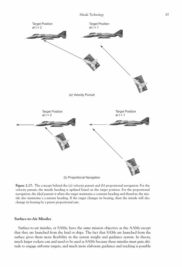
87Missile Technology
Surface-to-Air Missiles
Surface-to-air missiles, or SAMs, have the same mission objective as the AAMs exceptthat they are launched from the land or ships. The fact that SAMs are launched from thesurface gives them more fl exibility in the system weight and guidance system. In theory,much larger rockets can and need to be used as SAMs because these missiles must gain alti-tude to engage airborne targets, and much more elaborate guidance and tracking is possible
Figure 2.17. The concept behind the (a) velocity pursuit and (b) proportional navigation. For thevelocity pursuit, the missile heading is updated based on the target position. For the proportionalnavigation, the ideal pursuit is when the target maintains a constant heading and therefore the mis-sile also maintains a constant heading. If the target changes its bearing, then the missile will alsochange its bearing by a preset proportional rate.

88 Military Technologies of the World
using a network of ground-based radars. Also, highly effective portable systems such as theU.S.-made Stinger missiles and Russian 9K38 “Igla (Needle)” (SA-18 Gremlin) are avail-able. Table 2.3 lists some of the major SAMs in the world.
The SA-series missiles are Russia’s fl eet of SAMs and range from long-range, two-stagemissiles to portable shoulder-fi ring systems such as SA-7, SA-14, and SA-18. The SA- isactually the U.S. identifi cation of the Russian missile, while names like “Guideline,”“Gladiator,” and “Giants” are used by NATO forces. The Russian designations vary de-pending on the type of the missile.
Table 2.3. Major SAMs of the World’s Military.
Country of Origin Military Designation, Name Guidance Method
Canada MIM-146, ADATS RadarFrance Crotale
MistralERYX
IRIRVisual
France/Germany Roland RadarIndia Akash Missile
Trishul MissileRadarRadar
Israel Arrow RadarJapan Type 91 IRPakistan Anza MKI
Anza MKIIAnza MKIII
IR, Shoulder-launchedIR, Shoulder-launchedIR, Shoulder-launched
People’s Republicof China
Romania
HQ-9KS-1HQ-7CA 94
RadarRadarIRIR
CA 95 IRRussia SA-1 “Guild”
SA-2 “Guideline”SA-3 “Goa”SA-4 “Ganef”SA-5 “Gammon”SA-6 “Gainful”SA-7 “Grail”SA-8 “Gecko”SA-9 “Gaskin”SA-10 “Grumble”SA-11 “Gadfl y”SA-12A
“Gladiator”SA-12B “Giant”SA-13 “Gopher”SA-14 “Gremlin”SA-15 “Gauntlet”SA-16 “Gimlet”SA-17 “Grizzly”SA-18 “Grouse”SA-19 “Grisom”SA-20 “Triumf”
RadarRadarRadarRadarRadarRadarIR, Shoulder-launchedRadarIRRadarRadarRadar
RadarIRIR, Shoulder-launchedRadarIRRadarIR, Shoulder-launchedRadarRadar
(Continued)

89Missile Technology
The SA-2 (V-750 Russian designation) is one of the older SAMs that have two-stagerocket motors. The booster stage has a solid-propellant rocket motor with a casing fi ttedwith four delta fi ns. The second- or the sustainer-stage rocket engine is fueled with liquidpropellant consisting of nitric acid and kerosene. The payload weight of up to 195 kg canbe carried, and this missile can be converted for delivery of nuclear armament. With aconventional high-explosive warhead, the missile has a kill radius of 65 m for jet fi ghtersand 100 to 120 m radius for severe damage. It makes up for any guidance inaccuracies witha large warhead. These missiles can reach speeds of Mach 4.0 to 4.5, with a maximum rangeof 30 km. The SA-2 missiles are over 10 m (33 ft) in length, and the deployment unitconsists of the truck-mounted transport and launch pad with an array of search-acquisitionand guidance radars. A typical deployment involves six launchers arranged in a hexagon,and the radars and fi re command operator van are hooked up with these launchers.
Table 2.3. Continued
Country of Origin Military Designation, Name Guidance Method
United Kingdom BlowpipeJavelinRapierSea CatSea DartSea SlugSea WolfStarstreakThunderbird
VisualVisualVisualRadarRadarRadarRadarLaser-guidedRadar
United States ChaparralFIM-43 RedeyeFIM-92 StingerGround-launched AM
RAAM-CLAWS (AIM-120AAM)
Ground-launched AMRAAM-SLAMRAAM(AIM-120 AAM)
MIM-3 Nike AjaxMIM-14 Nike HerculesMIM-23 HawkMIM-104 PatriotNike ZeusRIM-2 TerrierRIM-7 SparrowRIM-24 TartarRIM-66 Standard Missile-1RIM-67 Standard Missile-2RIM-156 Standard Missile-
2ERRIM-161 Standard Missile-3RIM-162 Eveolved Sea-
Sparrow Missile
IRIR, Shoulder-launchedIR, Shoulder-launchedRadar
Radar
RadarRadarRadarRadarRadarRadarRadarRadarRadarRadarRadarRadarRadar

90 Military Technologies of the World
The SA-7 (Russian designation Strela-2, 9K32) is a porta-ble, shoulder-fi red low-altitude SAM. Its U.S. equivalent isthe FIM-43 Redeye. The SA-7 is a small, portable missile andhas a small range of 4.2 km and an effective altitude from 15to 2300 m. Once launched, it reaches a supersonic speed ofMach 1.75, which is approximately 500 m/s or 1500 ft/s atthese altitudes. As with most portable SAMs, the SA-7 isequipped with a passive IR seeker (heat seeker). The SA-14(Strela-3, 9K34) is an improved version of the SA-7 and con-sists of the launcher and the missile, as shown in Fig. 2.18.Although similar in appearance as its predecessor, the SA-14(see Fig. 2.18) has a better range (4500 m), better altitude(3000 m), and more important a more sensitive heat-seekingguidance unit, using a cooled lead-sulfi de infrared detectorand a more accurate tracking algorithm.
A more advanced Russian system is the SA-15 Gauntlet.This system is complete with a transport/launch vehicle (seeFig. 2.19) that also carries radar and computer equipment. Athree-man crew (commander, system operator, and driver)
also ride in the vehicle turret. The vehicle is powered by a diesel engine but also is equippedwith a 75 kW gas-turbine electric generator. The ranging radar operates in the E/F bandsand provides complete coordinates (range, angle, and altitude) of up to forty-eight targets.The target type and range are fed to the onboard processing computer that can track andassess the threat levels associated with each target. The target tracking and missile guid-ance is performed by a separate radar operating in the G/H bands. The missile itself is 3.5m in length and has a launch weight of 170 kg, out of which 15 kg is of high-explosivearmament with a proximity fuse. To protect the launch vehicle, the missile initially ejectedwith a cold-launch device up to a height of 20 m and the solid-propellant rocket motor isturned on to reach a fi nal speed of approximately 850 m/s. Effective range is believed to be1500 to 20000 m at altitudes from 10 to 6000 m. At short range, this missile system isconsidered to be effective not only against aircraft but against incoming guided missiles asa missile defense unit.
As noted above, for the United States the AMRAAM can be launched from the air orthe ground, and the latter version bears the designation SLAMRAAM (surface-launchedAMRAAM) or HUMRAAM (HMMWV Humvee-launched). The SLAMRAAM is
Figure 2.18. The Russian SA-14 shoulder-launched SAM. The tail fi ns are retractable and engage once themissile is ejected from the launcher. Photo courtesy of the U.S. Department of Defense.
Figure 2.19. The transport vehicle forthe Russian SA-15 Gauntlet SAMs,complete with radar equipment andcrew cabin. Photo courtesy of the U.S.Department of Defense.

91Missile Technology
what the U.S. military refers to as CLAWS (complimentary low altitude weapon system),“complimentary” because these missiles are straightforward adaptation of the air-launchversion and provide compact and mobile defense against airborne threats. Along withMIM-23 Hawk and MIM-104 Patriot, SLAMRAAM adds a low-altitude, short- to medium-range component to the spectrum of air defense weapons to guard against incoming air-craft, helicopters, and cruise missiles. The initial target acquisition and fi re control ishandled by the army’s standard Integrated Fire Control Station, which receives signalsfrom the MPQ-64 Sentinel radar. The turreted launcher with six AMRAAM missiles canbe mounted on the Humvee (HMMWV, high-mobility multipurpose wheeled vehicle).Also, Raytheon in collaboration with the Kongsberg Defense Corp and the Norwegianarmy has developed a universal launcher consisting of six AMRAAM and three MIM-23HAWK missiles to provide a versatile air defense system.
MIM-23 HAWK (shown in Fig. 2.20) is one of the classic SAMs in the U.S. arsenalsince 1962, but through upgrades in guidance and propulsion units the viability of thesemissiles have been kept up to date. MIM-23 was designed as a ground-launch vehicle fordelivering 120 lbs of blast-fragmentation warhead and thus is coupled with a ground radarfor semi-active guidance. For the United States, the newer MIM-104 Patriot and the FIM-92A Stinger have replaced MIM-23, although such deployment leaves a gap in the rangeof engagement by either Patriot or Stinger. Raytheon and other licensed manufacturershave produced some 40,000 of these missiles, and they have been used in service by manyU.S. allies. With a range of 15 miles and a nominal target ceiling of 45,000 ft (higher inhigh-altitude versions), HAWK has provided a solid platform for defense against airbornetargets. The HAWK launch unit consists of a pulse acquisition radar to search high- ormedium-altitude targets typically with a 20 rpm rotation, a continuous wave acquisitionradar for low-altitude target search, two high power illuminator Doppler radar for targettracking and illumination, one back-up range-only radar, six launch vehicles with threemissiles each, twelve missile transport vehicle with a total of thirty-six missiles, and anumber of command/control and support equipment. This unit is manned by two offi cersand a crew of forty-nine men.
The Patriot (MIM-104) missiles are shown in Figs. 2.21 and 2.22 and have expandedtheir role from High to Medium Air Defense (HIMAD) to being the anti-ballistic missileweapon highlighted by the media exposure during the Persian Gulf War. The ground-based phased array tracking radar tracks and illuminates the target. The refl ected signal issensed by the passive radar on the missile head and transmitted to the ground engagementcontrol station (ECS), which computes the intercept trajectory and sends it back to themissile for actuator control in what is known as TVM guidance. In the recent upgrades asin PAC-3, however, active radar guidance replaces the TVM. Patriot is associated with theacronym “Phased Array Tracking Radar to Intercept of Target” for the above reasons. TheAN/MPQ-53/65 Radar Set includes the phased array radar for search and tracking, elec-tronic counter-countermeasure, and IFF (identifi cation friend or foe) and covers a 100-kmradius area. The ECS is housed in a 5-ton tactical cargo truck and includes the data linkterminal, the communication equipment, and the weapons control computer that runs theTVM intercept algorithm based on the radar signals. The data link connected to theM901 missile launching station allows remote control of the launch.
The Patriot missiles were introduced as the primary anti-aircraft missile to replace theNike Hercules in 1976. As described above, along with phased array radar and ECS thePatriot was a complete and expensive system. Using the Patriot platform, advanced ca-pabilities versions (PAC-1, -2, and -3) were developed to maximize the speed, range, in-tercept, and kill capabilities. Using the same 5.2-m length and 41-cm diameter missilecasing up to PAC-2, the missile speed increased to Mach 3 in PAC-1 and Mach 5 in PAC-2.

92 Military Technologies of the World
The PAC-3 upgrades, although still referred to as a Patriot missile, can be considered as anew missile with a much smaller diameter (25 cm), shorter range (15 km), and a com-pletely different tracking method. PAC-3 was manufactured by Lockheed Martin, in con-trast to Raytheon for prior versions, and now has a dedicated role of terminal defenseagainst ballistic missiles. The guidance accuracy is improved against high-speed targets inPAC-3 so that its primary function is hit-to-kill while a “lethality enhancer” of 73 kg ofhigh explosive blast and fragmentation warhead backs up the system with a proximity sensor.
Figure 2.20. Live launch of MIM-23 HAWK surface-to-air missile. Photo courtesy of the U.S. Army.

93Missile Technology
The smaller diameter allows up to sixteen PAC-3 missiles to be fi red from the launcher(eight for previous versions).
The media, the administration, and the manufacturer of the Patriot missiles depicted anexaggerated picture of the performance of the then–PAC-2 version in at least one instance,boasting forty-one out of forty-two Scud missiles destroyed by this anti-ballistic missile de-fense system. One known failure of the system involves the Scud hit of an army barracks inDhahran, Saudi Arabia, that resulted in loss of twenty-eight soldiers. The cause of the “mal-function” in the Patriot launch was attributed to a software error in main-taining an accurate internal timing clock, which had drifted by one thirdof a second—equivalent to an error of 600 m in estimating the incomingmissile location. This error caused the failure of the tracking radar to fi ndthe Scud missile and resulted in no intercept attempt (i.e., no launch).There have been counter-claims in which studies of the videotapesshowed no direct hits on the Scuds by the Patriot missile. However, thereare two extenuating circumstances to the claim. One is that Patriot mis-siles were originally intended as an anti-aircraft defense measure andtherefore were equipped with proximity fuses to detonate the warhead ifforeign objects were detected in the pre-set damage radius. Another fac-tor is that the crude construction of the Scud missiles often led to disin-tegration of the missile body during high-speed descent, and fragments ofthe missiles including the warhead would be detected by the radar. Al-though unintended, the effect was to create a number of decoy targets,much as modern ICBMs employ during the terminal phase of the fl ight.
Figure 2.21. MIM-104 Pa-triot missile. Photo courtesyof the U.S. Army.
Figure 2.22. MIM-104 Patriot missile launcher. Photo courtesy of the U.S. Department of Defense.

94 Military Technologies of the World
During the second deployment in the region, Operation Iraqi Freedom, the Patriotsystem did deliver confi rmed kills of the tactical ballistic missiles. Using the GEM-seriesupgrades to PAC-2 Patriot missiles and PAC-3s, Iraqi Al Samound-2 and Ababil-100medium-range missiles were engaged, intercepted, and destroyed. In addition, the com-plex Patriot launch units were by this time suffi ciently mobilized to provide forwardprotection of the air space in highly fl uid battle situations.
The Patriot missiles, however, did fi re on friendly aircraft. A British RAF TornadoGR4A was shot down with loss of two pilots after a number of ill-posed settings classifi edthe RAF aircraft as an anti-radiation missile (ARM). On the Patriot side, the target clas-sifi cation algorithm was set too wide, taking the radar and emission signatures of an air-craft like Tornado to be designated as an ARM. An ARM targets systems like the Patriotsystem’s ground radar, so that these targets are a high-priority, and the Patriot automati-cally engages the target without waiting for operator input. This automatic engagementalgorithm can be deactivated, but the operators had not done so in spite of the fact thatthere were no known ARMs in the Iraqi arsenal. On the Tornado side, the RAF aircraftmade its landing approach directly over the Patriot system’s forward site, making it appearas an imminent threat. Last but not least, the Tornado’s IFF is believed to have beenturned off at the time, giving the Patriot system an automatic go-ahead with the interceptlaunch.
In an incident involving the U.S. Navy’s F/A-18 Hornet, search radars from two sepa-rate Patriot batteries detected the aircraft and in both sites the Patriot target classifi cationalgorithm initially classifi ed it as a tactical ballistic missile headed toward the Karbala Gapregion where the U.S. Army contingent was operating. In one of the Patriot units, theoperator’s check of the target speed and altitude was inconsistent with the initial softwareassessment and the engagement protocol was manually halted. In the other, however, themanual check or override were unfortunately not made, resulting in a PAC-3 launch anda catastrophic impact a few moments later with the friendly aircraft. Again, an extenuat-ing circumstance in this incident is that the responsible Patriot battery’s radar had to bereplaced earlier after a friendly AGM-88 HARM missile destroyed its own radar in a re-versed case of mistaken identity. An Air Force F-16 pilot assumed that his aircraft wasbeing illuminated by a hostile SAM radar, as alerted by an onboard radar warning receiver,and in response fi red anti-radiation missile toward the Patriot radar. The replaced radar
had not fully been integrated and tested with thePAC-3 software when the above incident involv-ing F/A-18 Hornet occurred. With ballistic missilesincoming at high Mach speeds, the time to come toa snap decision was measured in seconds underhighly tense battle situations. The potency andMach 5-plus speed of Patriot missiles have thusproven that this is a viable defense against tacticalballistic missiles; however, both the target classifi -cation algorithm and operator judgment wouldhave to be near perfect to avoid unfortunate inci-dents as above.
The FIM-92 Stinger is a compact, short-rangeanti-aircraft missile that is primarily launched froma shoulder-mounted tube, although the same mis-sile has been adapted for fi ring from other platformssuch as the HMMWV-mounted launcher (Fig.2.23), AH-64 Apache, or OH-58D Kiowa Warriorhelicopters. A Stinger system has a total weight of
Figure 2.23. Stinger missiles can be fi red from agyro-stabilized air defense turret mounted on amodifi ed heavy High Mobility MultipurposeWheeled Vehicle (HMMWV, AKA Humvee).There are two launch tubes on the turret and up toeight Stinger missiles can be fi red.

95Missile Technology
only 34.5 lbs with the 22-lb missile and consists of launch tube, missile, and a battery pack.The operator points the missile toward the target through a sight attached to the launchtube, and after IFF query is made to confi rm the hostile identity the infrared sensor coolingis initiated. For short-range targets, the activated IR sensor may acquire the target prior tolaunch giving an audible indication (a growling noise), at which time the launch is madefi rst with the gas generator to eject the missile out of the tube. The solid propellant motorengages a few yards out of the launch tube, to protect the fi ring crew from the effects ofrocket plume and shocks. The missile itself is a 5-ft-long cylinder with a 2.75-in diameterand has rectangular forward pop-out wings and cruciform tailfi ns. The dual-thrust solidrocket motor generates speeds of Mach 2-plus and exceptional engagement altitude (over10,000 ft) and range (3 miles) for its size.
The “Standard” missiles are a series of air defense systems to protect vulnerable surfaceships developed for the U.S. Navy. The RIM-2 Terrier, RIM-8 Talos, and RIM-24 Tartarused by the navy in the 1960s were the precursors to the Standard missiles. The StandardRIM-66 replaces the Tartar for medium-range missions, while RIM-67 ER replaces theTerrier and Talos for extended range. Although intended as anti-aircraft and anti-missilemissiles, both RIM-66 and RIM-67 (Fig. 2.24(a)) can be fi red against surface ships usingtheir semi-active radar, radar homing, or inertial/IR guidance. The defi nition of mediumand extended range has evolved with the years. The RIM-66 missile has an impressiveeffective range of 40 km for the SM-1MR version and 70 km for the SM-2ER, while theRIM-67 SM-2MR version carries the warhead over a distance of 120 km and the SM-2ER“Block IV” 150 km. The diameters of both the RIM-66 and RIM-67 are identical at 0.34 m,
Figure 2.24 (a). Vertical launch of RIM-67SM-2 missile. The rocket exhaust plume escapesupward from a separate vertical slot adjacent to themissile tube. Photo courtesy of the U.S. Navy.
Figure 2.24 (b). Main components in the SM-2missile. Background photo courtesy of the U.S.Navy.
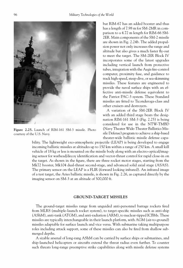
96 Military Technologies of the World
but RIM-67 has an added booster and thushas a length of 7.98 m for SM-2MR in com-parison to a 4.72 m length for RIM-66 SM-2ER. Main components of the SM-2 missileare shown in Fig. 2.24b. The added propul-sion power not only increases the range andaltitude but also gives a much faster fl y-outto meet the target. The SM-2ER Block IVincorporates some of the latest upgradesincluding vertical launch from protectivetubes, integration with the Aegis fi re-controlcomputer, proximity fuse, and guidance totrack high-speed, steep-dive, or sea-skimmingmissiles. These features are engineered toprovide the naval surface ships with an ef-fective anti-missile defense equivalent tothe Patriot PAC-3 system. These Standardmissiles are fi tted to Ticonderoga-class andother cruisers and destroyers.
A variation of the SM-2ER Block IVwith an added third stage bears the desig-nation RIM-161 SM-3 (Fig. 2.25) is beingconsidered for use in the NTW-TMBD(Navy Theater Wide-Theater Ballistics Mis-sile Defense) program to achieve a ship-basedtheater-wide ballistic missile defense capa-
bility. The lightweight exo-atmospheric projectile (LEAP) is being developed to engageincoming ballistic missiles at altitudes up to 150 km within a range of 250 km. A small killvehicle of 18 kg or less is mounted on the missile body along with an electro-optical/imag-ing sensor for warhead/decoy identifi cation and vector-thrust control for rapid close-in onthe target. As shown in the fi gure, there are three rocket motor stages, starting from theMk72 booster, Mk104 dual-thrust second-stage, and advanced solid axial stage (ASAS).The primary sensor on the LEAP is a FLIR (forward looking infrared). An infrared imageof a test target, the Aries ballistic missile, is shown in Fig. 2.26, as captured directly by theimaging sensor on SM-3 at an altitude of 500,000 ft.
GROUND-TARGET MISSILES
The ground-target missiles range from unguided anti-personnel barrage rockets fi redfrom MLRS (multiple-launch rocket system), to target-specifi c missiles such as anti-ship(AShM), anti-tank (ATGM), and anti-radiation (ARM), to nuclear-tipped ICBMs. Thesemissiles are typically interchangeable in their launch platform, with AGM (air-to-ground)missiles adaptable for surface launch and vice versa. With submarine taking multipurposeroles including attack support, some of these missiles can also be fi red from shallow sub-merged depths.
A sizable arsenal of long-rang AShM can be carried by surface ships or submarines, andship-launched helicopters or aircrafts extend the threat radius even further. To countersuch threats long-range preemptive strike capabilities along with missile defense systems
Figure 2.25. Launch of RIM-161 SM-3 missile. Photocourtesy of the U.S. Navy.

97Missile Technology
as described above are becoming absolutenecessities in modern navies. Small corvettesat the 3500-ton range can carry multiple 100km–range missiles capable of destroyingmuch larger naval vessels, and submarineswith 500-plus km–range missiles pose evengreater risk for large naval task forces. Heli-copters or aircraft with airborne radars caninitiate or coordinate over-the-horizon at-tacks. Rarely would naval vessels exchangeartillery rounds from visual range, but mostof the attacks and counterattacks would bemade in the radar space, giving the advan-tage to the side that possesses more advancedradars, attack weapons, anti-missile defensesystems, and commander/crew to deploythem with quick and sound judgments.
The American-made Harpoon andFrench Exocet rank as the most widely dis-tributed anti-ship missiles in the westernblock with an estimated 6000 sold to twen-ty-four customer nations for the former and3300 to thirty-two nations for the latter. The AGM-84 Harpoon may be considered as amulti-use anti-ship cruise missile, because its primary power plant is an air-breathing Tele-dyne J402 Turbojet engine with 660 lbs of thrust. Solid propellant boosters are added onship- and submarine-launch versions. After clearing the launch platform, the missile takesa low-altitude, sea-skimming, high subsonic trajectory toward the target as set by the radaraltimeter. During the terminal phase, the active radar seeks and locks onto the target, atwhich time the missile will maneuver a sudden pull-up and attack from above with itshull-penetrating 488-lb warhead. The Harpoon has many variants including a modifi ca-tion to a stand-off land attack missile (SLAM) to engage high-value land targets as shownbelow.
AGM-84D: All-weather, over-the-horizon Harpoon missile with high survivability andeffectiveness that can be fi red from the aircraft like the U.S. Navy’s P-3 Orion, surfaceships using Mk 116 TARTAR launcher, or submarines through the torpedo tubelauncher.
AGM-84D Harpoon Block 1D: Upgrade of AGM-84D with larger fuel tank and re-attack capability.
AGM-84E Harpoon/SLAM: Land-attack version of the Harpoon missile with the guid-ance replaced with GPS, inertial navigation, and infrared optical terminal guidance sys-tem. The payload is also replaced with the Tomahawk warhead for high-penetrationcapability.
SLAM-ER Block 1F: Provides long-range, high target penetration and control. Therange is nearly double the prior versions, at 150-plus miles, and the titanium warhead in-creases the impact energy. The pilot interface with the missile guidance allows re-targetingor target switching.
The Russian anti-ship missiles tend to be large and fast, in line with their militarydoctrine of countering the western carrier-centered surface warships with an abundanceof anti-ship cruise missiles. The Zvezda Kh-31 delivers 90 kg of warhead at a speed ofover four and a half times the sonic velocity using a solid-rocket booster to get up to
Figure 2.26. An infrared image of a test target, an Ariesballistic missile, as captured directly on the imaging sensoron RIM-161 SM-3 missile at an altitude of 500,000 ft.Photo courtesy of the U.S. Navy.

98 Military Technologies of the World
supersonic speeds fi rst, and the ramjet engine then takes over to propel the missile to itscruise speed. The behemoth-class missile is the 4800-kg P-500 Bazal or SS-N-12 Sand-box in western designation (in comparison to 532 kg for AGM-84D Harpoon). Thismissile also uses a solid-rocket booster to reach its cruise altitude of approximately 4000m, and then turns on its turbojet to cruise at a supersonic speed to the target vicinitywithin a radius of 250 km of the launch point. The radar seeker has a range of up to 90km, and once the target is locked on the missile assumes a low-altitude (about 100 m)path for the terminal phase.
Anti-armor munitions can make use of high kinetic or chemical energy. Kinetic energymunitions like APFSDS (armor piercing, fi n stabilized discarding sabot) rounds are fi redfrom tank guns, and chemical energy warheads like HEAT (high explosive anti-tank),HESH (high explosive squash head), FRAG-HE (fragmenting high explosive), and SC(shaped charge) are used in both tank artillery rounds and ATGM. The kinetic energypenetrators use high mass at relatively low velocities, while shaped charge warheads gener-ate low-mass, high velocity jets of 10 km/s using copper liner and 12 km/s with molybde-num liner to defeat the armor. Typical ATGM carry much more high explosive for theshaped charge or other warheads, and as an example, the AGM-114K Hellfi re II is esti-mated to deliver suffi cient penetration power to defeat all known tank armors. These mis-siles, due to their high energy capacity, are also used against concrete bunkers and hardenedfortifi cations. The standard guidance method is semi-active laser where the target needs tobe illuminated by the launch vehicle or a separate forward observation (FO)/combat ob-servation lasing team (COLT), but the AGM-114L Longbow Hellfi re has an active milli-meter wave radar seeker to independently complete its terminal homing. These missilesdeliver small-radius, concentrated energy to the target, so that the U.S. military has foundit to be an effective option during urban warfare situations. There are several launch op-tions for the Hellfi re missile, the surest of which is to allow the missile optical sensor toacquire the target prior to launch in the “lock-on before launch (LOBL)” mode. This allbut eliminates the risk of missile failing to fi nd and acquire the refl ected laser signaturefrom the target during its fl ight but does require the launch vehicle to be in view of thetarget at close range and low altitudes. Lock-on after launch (LOAL) reduces the risk oflaunch vehicle exposure, but there is a fi nite chance that the missile may fail to acquirethe target-derived laser signature and become unguided. LOAL-DIR mode sets a timedelay before the missile will start to seek the target. LOAL-HI and LOAL-LO modes pro-gram the missile to clear 1000 ft or lower terrain features before attempting to fi nd itstarget, so that the launch vehicle can remain hidden behind the terrain.
M-220 TOW (tube-launched, optically-tracked, wire-guided) missiles, shown in Figs.2.27 and 2.28, are the anti-tank analog of the anti-aircraft Stinger missile, where the ar-mor-penetrating warhead can be delivered from a compact launch tube. TOW missiles canbe fi red from a portable launch tube on a tripod, from HMMWV, from the Bradley Fight-ing Vehicle (BFV), or from helicopters and has a capability to penetrate through 30 in ofarmor within its effective range of 3 km. Steeply angled armors, reactive armors, and otherconstraints make the actual penetrable armor thickness much smaller, but still TOW hasproven to be lethal for most armored vehicles. The TOW missile uses a simple yet effectiveguidance method, where the launch operator to keeps the target within the cross-hairsusing a joystick to illuminate the target with an infrared beam. The missile itself has aninfrared beacon at the tail to communicate its relative position from the line-of-sight be-tween the target and the launcher as computed from the illuminating infrared beam. Thecorrective action to keep the missile in that line-of-sight is communicated to the missilevia two fi ne-gauge steel wires that are being rapidly unwound from the launcher. The mis-sile tail fi ns are then actuated by high-pressure helium to maintain the line-of-sight toward

99Missile Technology
Figure 2.27. TOW missile launcher with target sight and infrared sensors. Photo courtesy of the U.S. Army.
Figure 2.28. TOW missile tube on a tripod launcher. Photo courtesy of the U.S. Army.

100 Military Technologies of the World
the target until impact. The TOW missilehas a nominal length of 1.5 m and a diame-ter of 150 mm, although they vary somewhatfrom version to version. After the missileclears the launch tube using a short-burnlaunch motor, the forward and tail fi ns popopen, and the fl ight motor fi res up for 1.5 sbefore burning out. The missile is then es-sentially on a glide mode toward the targetat a speed of 280 m/s for a maximum rangeof 4 km.
The AGM-88 HARM (high-speed anti-radiation missile) shown in Figs. 2.29 and2.30 is another example of target-specifi cprojectile that is typically launched fromthe air toward ground-based radar installa-
tions. It locks on to signals from the opposing search-and-track radars. In a typical aircampaign, aircraft such as the F/A-18 and F-16 will attempt to pave the way for the wavesof aircraft by knocking out the SAM-guidance radars. The seeker searches for radio fre-quency emission sources and based on the priority set by internal software and pilot inputattacks high-priority radars using preformed steel (25,000 fragments in AGM-88B) ortungsten (12,845 fragments in AGM-88C) warheads to knock out the radar structure.Because radars do not respond to IFF queries and frequency spectra are similar betweenfriendly and hostile emitters, ARMs in general do not have discriminating ability nor steercapability so that the human interface in the target acquisition and priority loop is moreimportant than other missiles. In fact, as noted above a HARM missile was erroneouslyfi red against a U.S. Patriot radar site during the Operation Iraqi Freedom disabling thesystem. The HARM missile can also be launched from A-6E and A-7 attack aircraft andEA-6B Prowler electronic countermeasure aircraft.
MISSILE PROPULSION
There are mainly two propulsion systems used in modern missiles. The fi rst is the rocketengine, which in turn can be classifi ed into solid or liquid propellant rockets. The otherpropulsion system is the gas-turbine engine and its variant. For air-to-ground assaults,guided or unguided bombs are also used relying on gravity to fall to the target.
The rockets are propelled by burning the propellant that is essentially explosive mate-rial. The rocket propellant generates a large volume of hot gas, which creates a high-pressure, high-temperature environment in the rocket combustion chamber. Contrary topopular belief, it is neither the hot exhaust from the rocket nozzle pushing against theoutside air nor the pressure difference caused by the nozzle opening that generates thrust.It is the large mass of the exhaust gas accelerating out the nozzle that gives the rocket theforward momentum. This is called the “conservation of momentum,” or Newton’s secondlaw. We can visualize it as an event where if a high-speed object such as a baseball is caughtby the catcher he will feel a force pushing him backward. This force will be greater forlarger masses and higher speeds, which are collectively known as the momentum (masstimes the velocity). The exact converse also holds: If a device is able to eject a large massat a large velocity, the system will be subject to a forward force. This is how both the rock-ets and gas-turbine gain momentum: They eject a large mass of exhaust gas at a high velocity
Figure 2.29. HARM (high-speed anti-radiation missile)mounted on a Navy F/A-18 aircraft. Photo courtesy of theU.S. Navy.

101Missile Technology
out the nozzle. The major difference between the rockets and gas-turbine is that rocketscarry both the fuel and oxidizer needed to complete the propellant burning while the gas-turbine carries only the fuel and needs to ingest air. The ingested air also brings in back-ward momentum, so there is a limit to how fast gas-turbine-powered missiles can move.
There are two types of rocket propulsion systems: solid propellant and liquid propellant.Solid-propellant rocket motors tend to be less expensive and easy to maintain and as suchare used in missiles with small to intermediate size. Therefore, for so-called tactical mis-siles such as the air-to-air or ground-to-air, solid propellants are primarily used as the rocketfuel. The solid propellants contain both the fuel and oxidizer components. These solidpropellants go by names like HTPB or NEPE, which stand for hydroxyl-terminated polyb-utadien and nitrate-ester plasticizer. Fancy names, but they are pseudonyms for materialthat contains organic or hydrocarbon plasticizer as fuel and chemicals like nitrates or per-chlorates as oxidizers. Table 2.4 lists some typical solid propellants used in tactical missiles.In spite of their explosive properties, under controlled conditions of surface-burning theyonly burn at about half an inch per second. So if the rocket packed a solid propellant in a2-in-thick cylindrical shell, it will burn for about four seconds, and after that the rocket isjust coasting but at a very high speed for a while. The hot gas from burning of these solidpropellants reaches a temperature of 4000 to 6000 o F. With all the hot gas product from thepropellants, the pressure inside the rocket combustion chambers (sometimes called rocketmotors although there aren’t any moving parts in solid propellant rockets) quickly reachesfi fty times the atmospheric pressure or above. This high-pressure gas then rushes outthrough the rocket nozzle, thereby ejecting large momentum. That is how the thrust isgenerated in solid-propellant rockets.
Figure 2.30. A HARM missile fi red from an F-16: a view from the cockpit. The exhaust and multiple shocksystem trailing the missile are visible. Photo courtesy of the U.S. Air Force.

102 Military Technologies of the World
In Table 2.4, the double-base propellants refer to a mix of nitrocellulose and nitroglyc-erin, which forms a gel when combined together. Different mixture ratios of nitrocelluloseand nitroglycerine are used along with a number of plasticizers to improve mechanicalproperties and stabilizers to ensure durability during storage. Variants of the double-basepropellants have names like Ballistite, Cordite, French S.D., and AFU but essentiallyrepresent the above variations and bear similar properties. Ammonium perchlorate is apotent oxidizer commonly used in solid rocket propellants with a chemical formula ofNH4 ClO2 . The propellants listed in Table 2.4 include various binders (fuel component ofthe propellant that also acts as a form-shaping material) such as polyvynil chloride, poly-sulfi de, NEPE, and HTPB combined with ammonium perchlorate. Other binders in solidrocket propellants are actually quite common materials such as polyester, synthetic rubber,polyethylene, polyurethane, and polybutadiene, basically anything that will burn and holdthe propellant shape and properties. HTPB (hydroxyl-terminated polybutadiene) is thefuel component used for the space shuttle solid rocket boosters. Aluminum particles whenembedded into these propellants not only burn and add energy, but also act as high-massparticles to add to the total momentum produced by the propellant.
Liquid-propellant rockets, while being more complex and therefore also more expen-sive, have a number of advantages. First, they have a much higher exhaust velocity. Thismeans that for each pound of propellant more momentum and therefore thrust can begenerated. Typically, solid-propellant rocket exhaust is in the range of 2000 to 2500 m/s,whereas for liquid-propellant the exhaust jet can reach speeds of 4400 m/s. In fact, therocket exhaust divided by the gravitational acceleration (9.81 m/s2 ) is a standard measureof the rocket’s ability to generate thrust per given mass of propellant and is called the spe-cifi c impulse. So for solid-propellant rockets, the specifi c impulse is around 200 to 250,while for liquid-propellant rockets it can be as high as 450. The second advantage of theliquid-propellant rockets is that the fuel and oxidizer fl ow to the combustion chamber canbe metered or shut off altogether and turned on again as desired. This gives a control of therocket thrust where there is none for the solid-propellant rockets. Once the solid propel-lant is ignited, there is no stopping it. Even though many technologies have evolved toprovide much greater thrust in modern rocket engines, the essential components remain
Table 2.4. Solid Rocket Propellants Used in Tactical Missiles.
Propellant
Metal Content(percent by
weight)
Density(lbs percubic in)
CombustionTemperature
(°F)Isp = Specifi c
Impulse1
BurningRate(in/s)
Double-base with ammoniumperchlorate and aluminum
20 ~ 21 0.065 6500 260 ~ 265 0.78
Cross-linked double-basewith ammonium perchlorate
19 0.067 6060 269 0.35
Polyvinyl chloride withammonium perchlorate
21 0.064 5600 260 ~ 265 0.45
Polysulfi de withammonium perchlorate
3 0.062 5000 240 ~ 250 0.31
NEPE, nitrate-ester plasticizer 16 0.064 5800 260 ~ 263 0.55HTPB, hydroxyl-terminated
tetranitramine withammonium perchlorate
14 0.064 5400 ~ 5600 260 ~ 265 0.32
1Isp = specifi c impulse = the thrust force for one pound of propellant burned in one second.

103Missile Technology
the same in liquid-propellant rocket engines. They include storage for both fuel and oxi-dizer, the combustion chamber, and turbo- or other machinery to deliver the fuel and oxi-dizer to combustion chamber operating at high pressures up to 100 to 200 times theatmospheric pressure.
Gas-turbines are used in cruise missiles due to their large thrust-to-weight ratio and ef-fi ciency in terms of thrust per mass of fuel burned. The way they generate thrust is essen-tially the same as rockets: They eject high-momentum exhaust gas out through the nozzleto gain forward momentum. One major difference is that the gas-turbine engines need toingest air to mix with fuel and burn and also to carry the energetic combustion productgas. The incoming air carries with it some negative momentum, so the jet momentummust exceed the incoming air momentum to provide positive thrust. This puts a limit onthe maximum speed achievable through gas-turbine engines, whereas for rockets there isno theoretical limit on the top speed. For gas-turbine engines, the operation follows thesequence: The air comes in, gets compressed through a compressor, gets mixed with fueland burnt in the combustor, runs through a turbine, and then accelerates down and outthrough the nozzle. This sequence is illustrated in Fig. 2.31. A turbofan engine has a fansection in addition to the main gas-turbine engine. The fan adds momentum to the in-coming air and sends it out through the fan nozzle at higher momentum and thus is a de-vice to gain thrust in an effi cient manner. For gas-turbine engines for commercial airliners,the fan section tends to be large because the fuel effi ciency is a much bigger consideration.For gas-turbine engines for military fi ghter aircraft, both the range (fuel effi ciency) andhigh-speed operations are of concern so that they tend to have a smaller fan section. Forcruise missiles, the fan section may be yet smaller or nonexistant depending on the opera-tional speed and range of the missile. For supersonic cruise missiles, a ramjet engine—avariant of the gas-turbine engine—is used.
The main components of a gas-turbine engine are shown in Fig. 2.31. The compressoris connected to the turbine, so the compressor work is internally produced by the turbine.The energy released from the burning of the fuel with air in the combustor turns the tur-bine, which in turn turns the compressor and the fan. The remaining energy is convertedto kinetic energy in the form of high-speed exhaust.
A ramjet engine is a simplifi ed version of the gas-turbine engine, where the air compres-sion is accomplished by the excessive momentum of the incoming supersonic stream.Supersonic fl ow of air becomes hot and highly pressurized when slowed down throughthe supersonic inlet. Such ram compression only occurs at supersonic speeds, so ramjet
Figure 2.31. A schematic showing the main components of a turbofan engine.

104 Military Technologies of the World
engines can only be operated at supersonic speeds. Since a cruise missile or any aircraftneeds at some point to start from a standstill and go through subsonic speeds to attain su-personic speeds, ramjet-powered aircraft need an initial booster such as a solid rocketmotor to accelerate to supersonic speeds before the ramjet can be operated. The ram com-pression then replaces the function of the complex and heavy compressor and turbine inconventional gas-turbine engines. Ramjet engines therefore can be considered a largecombustor tube with the inlet and nozzle designed to maximize the ram compression andexhaust acceleration.
CRUISE MISSILES
Cruise missiles are intermediate- to long-range missiles that follow a programmed pathfor highly accurate delivery of conventional and nuclear armaments toward stationary orslow-moving targets (land targets or ships). They are fl ying objects in the sense that theyhave wings to provide lift during the fl ight, and the power plants used for cruise missilestend to be variants of gas-turbine engines (e.g., turbofan or ramjet engines). The fl ightpath is typically low altitude to avoid radar detection and intervention. Modern guidancetechnology discussed earlier in this chapter allows for precise targeting using a combina-tion of GPS (global positioning system), TERCOM (terrain contour matching), andDSMAC (digital scene-matching area correlator). Depending on the cruise missile rangeand capabilities, cruise missiles carry a price tag ranging from $500,000 to $2,000,000. Intheory, this high price per missile predicates that only high-priority targets should be des-ignated for cruise missile missions. However, as recent events in the Iraq theater haveshown, other constraints such as the large volume of targets and anti-aircraft defensearound the targets can also dictate the use of cruise missiles.
A cruise missile is essentially an unmanned aircraft, and in that sense the German V-1,the buzz bomb, is the predecessor of all modern cruise missiles. The U.S. armed forces useseveral cruise missiles that can be launched from submarines, ships, or aircraft. A U.S.Tomahawk (BGM-109) cruise missile is shown in Fig. 2.32. Since the take-off is powered
Figure 2.32. Tomahawk (BGM-109) cruise missile. Photo courtesy of the U.S. Department of Defense.

105Missile Technology
Figure 2.33. Harpoon anti-ship missile. Photo courtesy ofthe U.S. Department of Defense.
Table 2.5. Various Cruise Missiles Deployed by World’s Major Armed Forces.
Type Designation/Name Country of Origin
Long-Range (Greaterthan 1000 miles),Subsonic
Kh-55, GranatTammuzBGM-109, Tomahawk (ship-
launched)AGM-86B, Tomahawk
(air-launched)
RussiaIraqUnited States
United States
Medium-Range (500 ~1000 km), Subsonic
Storm ShadowKEPD 350, TaurusBabur
United Kingdom/FranceGermanyPakistan
Short-Range (100 ~500 km), Supersonic
P-500, BazaltP-270, MoskitP-800, OniksP-700, GranitPJ-10 BrahMos
RussiaRussiaRussiaRussiaIndia/Russia
by an auxiliary solid rocket booster, a cruise missile only needs a small wing to maintain itscruise lift along with control and stability tail fi ns. Modern versions of the Tomahawk mis-sile include capabilities to pre-program up to fi fteen different targets with video monitor-ing capability of the specifi c targets, so that the fi nal target selection can be made by theweapons control offi cer in response to rapidly evolving battlefi eld situations.
The Tomahawk cruise missiles have a length of 20 ft 6 in at launch, and 18 ft 3 in afterthe launch booster has been jettisoned. As noted previously, a wing span of only 8 ft 9 inis suffi cient to maintain the cruise fl ight. The turbofan power plant (Williams Interna-tional F107-WR-402) propels the missile at a subsonic cruise speed of 550 mph.
Table 2.5 lists cruise missiles developed and deployed by the world’s major armed forces.
REFERENCES
Clancy, Tom. Fighter Wing: A Guided Tour of an Air Force Combat Wing . New York: Berkeley Press,1995.

106 Military Technologies of the World
Jensen, G.E., and D.W. Netzer (eds.). “Tactical Missile Propulsion,” Progress in Astronautics andAeronautics , Vol. 170. Reston, VA: American Institute of Aeronautics and Astronautics, 1996.
Laur, Col. Timothy M., and Steven L. Llanso. Encyclopedia of Modern U.S. Military Weapons .New York: Berkeley Books, 1995.
For more information on U.S. missiles, see the following Web pages: en.wikipedia.org/wiki/Missile_guidance, en.wikipedia.org/wiki/Air-to-air_missile/List_of_air-to-air_missiles, and www.globalsecurity.org/military/world/russia/missile.htm.

HELICOPTERS USE ROTORS with variable pitch angle (inclination angle) to provideagile motion, including stationary hovers. With powerful gas-turbine engines to turn high-thrust rotors, a formidable arsenal can be carried with agile mobility by modern attack he-licopters. The helicopters have proven their usefulness in many operations including troopand material transport, reconnaissance, medical and other evacuations, airborne commandposts, naval anti-submarine missions, and minesweeping operations. As has been the casethroughout the history of armed confl icts, however, innovations bring about counter-innovations. In spite of their strength against conventional opponents (e.g., those in hard-ened bunkers and mechanized vehicles), helicopters nowadays are becoming vulnerable tosmall projectile weapons such as shoulder-launched missiles or even rocket-propelled gre-nades fi red from a close range. Helicopters’ large cross-section, low operational altitude, andrelatively low speed make them reachable targets by small projectiles fi red from the ground.Nonetheless, few with any intention of survival would take on fi repower of the magnitudecarried by an attack helicopter like AH-64 Apache under normal battle situations.
The U.S. attack helicopter Apache, AH-64, shown in Fig. 3.1 symbolizes the fi repowerthat can be wielded by military helicopters. AH-64 is powered by two main gas-turbineengines (two General Electric T700-GE-701 turboshaft engines) with 1696 horsepoweroutput each plus an auxiliary power unit (APU). The main engines power the main rotors;the APU supplies electrical and mechanical power while the main engines are shut downon the ground. As shown in the photograph, the armaments that can be carried on anApache helicopter include a machine gun (M230 30-mm chain gun with 1200 rounds),rocket launcher (Hydra 70 FFAR rockets), and a combination of missiles (AGM-114Hellfi re, AIM-92 Stinger, AIM-9 Sidewinder, TOW missiles, and AGM-122A Sidearmanti-radar missiles). In the Navy’s Sea Apache version, AGM-84 Harpoon anti-ship mis-siles can be carried, as well as Penguin Mk2 Mod7 missiles. Other outboard equipmentthat can be carried includes the long-range fuel tank, an M130 chaff/fl are dispenser, andthe ALQ-144IRCM pulsed jammer.
Attack helicopters are most effective against ground targets such as hardened bunkersand armored vehicles. These helicopters can approach targets from low altitudes to avoiddetection and strike from the air. This makes armored vehicles particularly vulnerablebecause their guns have limited elevations. In fact, during the Desert Storm Operationsome 500 Iraqi tanks were destroyed by the Apache attack helicopters in the absence ofany air cover for the Iraqis.
The Apache helicopter has an in-line cockpit arrangement with the gunner in the frontand the pilot in the rear cockpit. Both are aided with a number of pieces of advancedelectronic equipment. There is a sensor eyepiece that the gunner can look into with both
CHAPTER
3
HELICOPTER FORCE

108 Military Technologies of the World
Figure 3.1. The U.S. Army’s attack helicopter, the Apache AH-64. Main components visible onthe exterior of the helicopter are shown. PNVS is pilot night vision system. TADS is the target ac-quisition and designation system. Photo courtesy of the U.S. Army.
eyes that is connected to the night vision and target acquisition displays. The sensor mod-ule for the TADS/PNVS (target acquisition/designation system and pilot’s night visionsensor) is located at the nose of the helicopter. TADS is a combination of a direct-viewdevice with wide-angle (18o ) and magnifi ed (4o ) fi eld-of-view optics, a TV camera, a lasertracker, and a laser rangefi nder/designator. The entire system rotates on a turret with a

109Helicopter Force
120o horizontal scan and +30o to –60o elevation range. The PNVS is a FLIR (forward-looking infrared) vision system, mounted on a separate turret. In addition, the gunnerlooks at a number of laser target tracking and control gauges in a central LCD display,along with fl ight data gauges (the gunner is also the co-pilot). The pilot’s cockpit is similarto that of an aircraft, again augmented by video display. An integrated helmet and displaysight system (IHADSS) allows the gunner to view the infrared night/adverse-weather dis-plays through a monocular viewer connected to the helmet. Critical fl ight data are dis-played on the monocle, such as air speed, altitude, and heading. In addition, the IHADSStracks the gunner’s head movements to align the machine gun and rocket launcher in thesame direction. Other standard electronics include a UHF/VUF/AM/FM secure commu-nication radio, an IFF with secure encoding, an IR jammer, and a radar jammer.
On the attack helicopter OH-68, Kiowa Warrior, the sensor pod is mounted in a ratherlarge composite spherical dome above the rotors. Similar to the TADS/PNVS module onthe Apache, the sensors are gyro-stabilized and include a laser rangefi nder/designator, ther-mal imaging sensor, and video camera. This mast-mounted sensor pod has the advantageof all-around vision as well as minimum exposure of the helicopter body during observa-tions. There was some resistance to such an arrangement due to excessive vibration andthe weight of electro-optical sensors, which explains the confi guration preferred by theApache designers. However, with modern vibration isolation techniques and compactsensors, mast mounting is becoming more of a standard.
In modern aircraft, the heads-up display (HUD) allows the pilot the monitor the situa-tion without having to look down on the control panel displays. In attack helicopters, thisinterface of the digital displays is taken one step further in so-called head-mounted dis-plays (HMD). The IHADSS mentioned above combines the display functions with weap-ons control. The United States Army has been a pioneer in the use of HMDs in helicopters,and HMD technology was used in the AH-1S Cobras as early as 1970s. The U.S. Air Forceis in the process of incorporating these systems in the F-15, F-16, and F-22 fi ghters, whilethe Navy version will be implemented in F/A-18s. IHADSS displays the views from theFLIR imaging system and also tracks the head movements of the wearer to direct the nightvision cameras, guns, and rocket launchers.
The seats are armored and designed for crashworthiness to protect the occupant’s verte-brae. Shock-absorbing material and structural design are embedded in the seats, minus theejection rockets because this would not be possible due to the presence of the rotors in theejection path. The crew compartment is shielded by a roll bar, armor, and blast/fragmentationshields, and a blast-resistant (not bullet-proof) material is used for the wind shield. Thereis an IR-suppressing cover for the exhaust of the main engine to minimize the infraredsignature that many anti-aircraft missiles zero in on. The rotors are also designed to reducenoise. The gun turret at the bottom of the Apache helicopters is designed to avoid thecrew in the event of a crash landing.
The Apache attack helicopters have a top speed of 227 mph, with a cruise speed of 165mph. The diameter of the main rotor is 53 ft 8 in, and the height from the ground the tailrotor tip is 16 ft 10 in. The empty weight of an AH-64 is 10,624 lbs, but it can take off witha weight of over 20,000 lbs. The Apache helicopter was conceived to replace the UH-1Cobra and a monstrous helicopter called AH-56A Cheyenne made by Lockheed. With re-cent modifi cations and upgrades, export versions of this helicopter can exceed $56 million.The fi repower of AH-64 or its variants (AH-64D) has been purchased by Egypt, Greece,Israel, Japan, Kuwait, the Netherlands, Singapore, United Arab Emirates, and the UnitedKingdom, with several other nations scheduled to receive their shipment of the helicopter.
Apache helicopters have played key roles in numerous real battle situations. Althoughmost of the glory usually has gone to the fi ghter-bomber pilots during the much televised

110 Military Technologies of the World
attacks on Iraq, in both the 1991 Operation Desert Storm and the 2003 Operation IraqiFreedom, it was a lead task force of nine Army AH-64 Apaches, one UH-60 Black Hawk,and four MH-53J Air Force Pave Low helicopters that cleared a narrow radar-free passagethrough the Iraqi air defenses during the Operation Desert Storm. A limited number ofstealth fi ghters could be deployed against intense radar-illuminated regions, and the alliedfi ghter-bombers had some radar jamming capabilities; however, the risk and probable losseswere unacceptable if hundreds of aircraft had to fl y through a fully functional air defensesystem dotted all over the land with radar and anti-aircraft missile installations. An open-ing in the air defense system was identifi ed consisting of two Soviet-built radar installa-tions separated by sixteen kilometers. If these two sites could be knocked out, then theaircraft could fi lter through the remaining space to initiate strikes against other anti-aircraft sites as well as key military and infrastructure targets.
The fourteen helicopters referred to as the Task Force Normandy were divided into twoteams, and the operation commenced at 12:56 AM local time on January 17, 1991. TheApaches were given the task of carrying out the actual attacks, one Black Hawk served asa support helicopter, while the Air Force Pave Lows with their advanced navigation sys-tem guided the attack helicopters to the targets. The MH-53J has a more accurate naviga-tion system using satellite global position system and terrain-avoidance radar. The missionobjectives were to destroy the two radar installations to pave the way for a much larger aircampaign. These helicopters were chosen for this key mission due to their ability to fl y atlow speeds and altitudes, outside the detection envelope of the early warning radars. Theengagement plan was to knock out the site’s communication and power equipment so thatno alarm can be raised, and then neutralize the radar capabilities. To ensure success, twohelicopters were assigned for a given sector to alternately make assaults on the targets andverify the results.
The mission profi le called for reaching and attacking the targets by 2:38 AM , requiringclose to one hour and forty minutes of fl ight in near total darkness. In spite of the ad-vanced designs and electronics, fl ying in Apache helicopters is not a joyride. The cockpitsare fi lled with displays and controls, and the pilot and the gunner both sit in crampedcockpit seats wearing a survival vest and a chest protector, plus the IHADSS helmet, inconstant noise and vibration while all the preparations for the assault need to be physi-cally and mentally made. The low-altitude and low-speed approach in the cover of dark-ness allowed the task force to reach its respective targets. At 6.5 kilometer from the target,the helicopter squadron adjusted the altitude to 150 feet from the ground, and soon afterthe onboard APR-39 radar warning receiver started beeping indicating that an activeradar beam was illuminating the helicopters. However, the warning signal was simply dueto the presence of high-power radars beaming upward into the empty nighttime sky, andthe attack group approached the targets without being discovered. If anyone was alertenough within the Iraqi radar installations, he may have wondered about the source of thisapproaching roar of seven helicopters.
The fi rst target was the command-and-control (C&C) vehicle parked in the vicinity ofthe actual radar site, and it is the C&C that communicates any of the radar warnings tothe rest of the Iraqi military chain of command. To maintain the integrity of the entirebattle plan, it was essential to cut off this communication channel with the fi rst shot.Using the FLIR display integrated to the target acquisition/designation system (TADS),the gunner located the C&C van and placed it in the cross-hair of the TADS display. Thiskept the target illuminated by a laser so that the Hellfi re missile could follow this brightspot on the target. TADS has capabilities to engage multiple weapons on the same target,and two Hellfi re missiles primarily used for anti-tank attacks locked on to the C&C unit. Asthe gunner pressed on the fi re button, the two missiles fi red off its launch pods in sequence.

111Helicopter Force
The display now counted the time to impact on the lower corner, but close to the zerocount a gigantic explosion could be seen on the gunner’s FLIR that also caused the laserlock to be lost because the radiation from the explosion overwhelmed the laser illumina-tion. The fi rst Hellfi re thus sailed into the big fi reball adjacent to the target. Fortunately,the fi reball subsided rather quickly to allow the second Hellfi re to maintain its course andhit the target. It turned out that the initial explosion that threw the fi rst Hellfi re missileoff was the zealous work of the second attack helicopter whose target was the power gen-erator in close proximity of the C&C van. With the C&C capability knocked out, theApaches used the remaining Hellfi re missiles on the radar itself, while spraying any hardobjects and likely targets with Hydra 70-mm missiles and cannon fi re after all the primarytargets were engaged and confi rmed destroyed.
The outcome at the other radar site was equally successful, with the entire attack phasebeing completed in less than fi ve minutes, and all fourteen helicopters returned to thelanding point. Long before the arrival, however, the Operation Desert Storm was alreadyunderway with aircraft streaming through the corridor established by the Apaches andsupport helicopters.
Not all helicopter operations have gone as planned. One of the more publicized heli-copter operations gone awry has been discussed in several books and even been made intoa Hollywood movie. The “Black Hawk Down” sequence of events, offi cially known as the“Battle of Mogadishu,” occurred in 1993 within the rather turbulent surroundings of So-malia that pitted the UNOSOM II (United Nations Operations in Somalia) forces againstthe Somali militia fi ghters. UNOSOM II’s intent was to bring about peace, law, and orderby disarming and reconciling the opposing sectors in Somalia. The U.S. elite special op-eration teams from the Army Delta Force, the Navy SEALs, and Army Rangers were in-volved in a UNOSOM operation that called for capture and extraction of high-prioritypersonnel targets of the Habr Gidr clan. The Habr Gidr clan was one of the feuding fac-tions in Somalia headed by a Somali warlord, Mohamed Farrah Aidid, and was known forits well-armed and often violent militia force.
The plan was to use the MH-60 Black Hawk helicopters to send in the special operationstroops, rendezvous with substantially larger teams of troops to go in by a ground convoy,and get out. However, the ground convoy was delayed by a series of road barricades consist-ing of rocks, burning tires, and so forth. In addition, an Army Ranger was seriously injuredduring a rope-down from a height of 70 feet. In the melee surrounding the mishap, a BlackHawk helicopter was shot down by a rocket-propelled grenade. In the densely populatedcity environments, the likelihood of direct hits from these RPGs being fi red from close,well-hidden locations must have been very high. The ensuing confusion and breakdownsin linking with the reinforcements resulted in another MH-60 Black Hawk helicopterbeing shot down, and thirty-four UNOSOM troops being killed, including nineteen U.S.servicemen. Two of the killed were Delta Force snipers who volunteered to be inserted bya helicopter to the site of downed Black Hawk in the hope of rescuing the injured pilot andcrewmen. The MH-60 Black Hawks with relatively light armor in comparison to, for ex-ample, the AH-64 Apache, were made vulnerable in the densely populated landing areaand by long exposure to militia attacks due to a series of unforeseen mishaps.
HELICOPTER FLIGHT
In Chapter 1, we saw how different aerodynamic surfaces like the ailerons and verticaland horizontal stabilizers can control the fl ight of the so-called fi xed-wing aircrafts. Bycontrast, rotary-wing aircrafts like helicopters use the tilt angle of the main rotor to alter

112 Military Technologies of the World
their fl ight paths, as illustrated in Fig. 3.2. Therotating rotor produces thrust in the directionperpendicular to the plane of rotation. The ver-tical component of the rotor thrust is the liftthat counteracts the weight of the helicopter.The horizontal component of the rotor thrustthen propels the helicopter forward by over-coming the drag force, as shown in the fi gure.The rotor can also be tilted from one side to theother, steering the helicopter in that direction.Thus, in helicopters the rotor produces the liftand forward thrust as well as the side forces. Byincreasing the helicopter angle and the rotorangle, more rotor thrust can be aligned in theforward direction to increase the net thrust.
But we have a rotating axis for the rotor, andhow the rotor plane of rotation is made to varytakes some engineering ingenuity. To see howthis works, we can begin by looking at the rotorhub in Fig. 3.3. The rotor is connected to therotor axis, which in turn is typically powered bythe turboshaft engine. The rotors are also con-nected to the upper swash plate through thepitch link. The upper swash plate moves with therotor while the lower swash plate is stationary.
They remain in contact through bearings that allows the upper swash plate to move withrespect to the lower swash plate. In a conventional helicopter cockpit, there are three con-trol levers: collective-pitch lever, cyclic-pitch lever, and the tail rotor control pedals. Thecollective-pitch lever, or collective for short, is located to the left of the pilot’s seat and sim-ply moves the lower swash plate up and down through hydraulic and mechanical links. Themovements of the lower swash plate will result in an identical motion of the upper swashplate, as shown in the fi gure, which in turn will change the pitch angle of the rotors. Forexample, when the pilot pulls up on the collective lever, there will be an upward movementof the swash plates that increases the rotor pitch. High rotor pitch generates higher lift forceswith greater torque required to turn the rotors. For this reason, the collective control is con-nected to the engine throttle via a correlating unit. If the rotor pitch is increased by thecollective requiring larger torque, the engine throttle is increased by a preset amount. Theexact change in the engine torque can be fi ne-tuned using a twist-grip type engine rpm con-trol at the end of the collective lever. To pull the helicopter off the ground, the pilot pulls upon the collective to increase lift as well as the engine power. As the rotor torque thus in-creases, the tendency for the helicopter to rotate in the opposite direction becomes stronger.To offset this tendency, the tail rotor is controlled by the pedal.
The cyclic control lever determines the tilt of the swash plates. Moving the cyclic forward,aft, left, or right causes an inclination of the swash plate. For example, for a helicopter motionto the right, we have the cyclic control pushed forward to cause a tilt in the swash plates. Now,when the rotor is in the left position its pitch angle will be increased while the opposite willhappen as the rotor turns to the position on the right. At higher pitch angle, again larger liftis produced and vice versa. This creates an asymmetry in the rotor lift on the forward and aftsides of the rotor rotation, which tends to turn the rotor to a forward-inclined plane shown inthe fi gure. The rotors have a range of motion in all three axes in so-called fully articulated
Figure 3.2. The forces acting on a helicopter duringfl ight.

113Helicopter Force
rotor hubs. The motion in the direction perpendicular to theplane of rotation is called “fl ap,” and it is the fl ap angle changeupward in the aft and downward in the forward side of therotation that changes the tilt angle of the rotor rotation. Thetilting of the rotor rotation plane turns the force vector andthus causes motion in that direction. Side motion follows thesimilar principle, enacted when the cyclic is pulled left orright. In a typical take-off, as the collective is pulled up thecyclic is pushed forward so that the helicopter gains speed aswell as stand-off distance from the ground. The forward speedadds a wind velocity component across the rotors to increasesthe lift forces, and thus makes it much easier for the helicopterto lift off particularly under heavy load conditions. This stan-dard maneuver is called “translational lift.”
A partial view of a helicopter rotor hub is shown in Fig. 3.4,where the large cylindrical object at the center is the rotorshaft. Two of the control cylinders are also visible. The toppart of the rotor hub is shown where the rotor blades are
Figure 3.3. Components of a helicopter rotor hub and its control using collectiveand cyclic.
Figure 3.4. A partial view of the rotor hubof the Air Force HH-60G Pave Hawk heli-copter. Photo courtesy of the U.S. Air Force.

114 Military Technologies of the World
attached along with other mechanical components like the fl apping hinge, drag hinge,and lag dampers in a fully articulated hub. We saw above that the pitch of the rotors canbe cyclically controlled about the rotor hinge. The fl apping hinge allows the rotor tomove up and down to tilt the rotation plane of the rotors, as controlled by the cyclic. Inaddition to tilting the plane of rotor rotation, the fl apping compensates for the differen-tial lift generated by forward- and backward-moving rotors. As shown in Fig. 3.5, if welook at a counterclockwise rotor rotation from the top, the right half of the rotor will seea greater velocity because it is moving against the air. For example, for a helicopter mov-ing at 120 mph with a rotor tip speed of 400 mph, the right rotor tip will be traveling at520 mph while the left rotor is actually moving backward at 280 mph. For a given bladepitch angle, the lift is proportional to the square of this relative air velocity, so that theright half of the rotor will generate a much greater lift than the left. This will result inunbalanced lift as well as unbalanced torque on the rotor axis and the helicopter air-frame. Allowing the rotor to lift up at higher lift conditions alleviates this torque. Thus,it is the centripetal acceleration of the rotor and the lift force that will set the rotor ele-vation angle, since the rotors are free to move up and down in the fl ap direction. Withoutrotation, the rotors will tend to droop down under gravity, and there are lower stops forthe fl ap angle to prevent the rotors from completely leaning down. For marine helicop-ters, there are also upper stops to prevent high wind from knocking the blades upward. Inaddition to the pitch and the fl ap degrees of freedom, the rotors are also allowed to rotatein limited amounts in the drag direction, which is in the direction of the rotor motion.As the lift is varied by the pitch angle, so is the drag on the blades, which will causefl uctuations of the force in the drag direction. To alleviate mechanical stress associatedwith this fl uctuation in drag, the drag hinge is used to allow small back and forth rota-tion. The drag hinge is also useful in folding the blades in the horizontal plane, to line upall the blades in one direction so that the helicopters may fi t into small hangar spaces.Some of the mechanical linkages to connect the rotor hub to the main rotors are shownin Figs. 3.6 and 3.7.
Fully articulated hubs are already mechanically quite complex, much more so thanaerodynamic surfaces on fi xed-wing aircraft, simply because they involve multiple, con-jugate rotations and translations. For this reason, high-lift aerodynamic devices such asfl aps (commonly used in fi xed-wing aircrafts) or boundary-layer control are not readilyimplemented on helicopter rotors although any increase in lift would enhance helicopterperformance. Flaps are retractable surfaces at the trailing edge of wings used to increasethe wing surface area and also the allowable angle of attack deployed during take-off andlanding of fi xed-wing aircrafts. Another high-lift approach called boundary-layer controluses compressed air blown through tiny slits or holes on the wing or the rotor to againallow high angles of attack. Another unique aspect of helicopter operation is the level of
Figure 3.5. The relative velocity between the air speed and the rotor speed.

115Helicopter Force
vibration arising from the rotation of rotors thatare typically imbalanced in the load conditions (liftand drag). For both civilian and military helicopterfl ights, excessive vibration is to be avoided for pas-senger comfort for the former and minimum crew/equipment fatigue and combat effi ciency for in thelatter. Even with the gyro and digital stabilizationin the targeting systems, it helps to have stable op-tical axes for aiming one’s weapons. There havebeen several innovative vibration isolation schemes,such as “Noda-Matic” and liquid inertia vibrationeliminator (LIVE). In the Noda-Matic, the fuselageis hung on the rotor hub and gear assembly on beamsor linkages that are allowed to move in limited amounts, and this movement is dampedby tuned masses to cancel as much as possible the vibration frequencies. In the LIVE typeof devices, the link between the fuselage and the propulsion train consists of pistondamper against heavy liquids like mercury contained in a cylinder. This acts like a shockabsorber, with elastomeric material liners inside of the cylinder further dampening thevibrations.
The helicopter controls include the collective pitch control lever, cyclic control stick,and the directional control pedals. The collective is typically located on the left side of thepilot’s seat, while the cyclic control is in front of the pilot as are the control pedals on thefl oor. As the collective is raised the overall pitch of the rotor increases requiring higherengine torque, and this in turn increases the overall tendency of the helicopter to rotatein the opposite direction of the rotor rotation. For example, for a counterclockwise rotorrotation as seen by the pilot, there will be a tendency for the helicopter to rotate in theclockwise direction since the helicopter is not anchored to the ground but rather is sus-pended in the air. To counter this torque, a gradually increasing amount of anti-torqueneeds to be applied by the tail rotor which is controlled by the directional pedals. Thus, asthe collective is raised, the pilot pushes down on the left pedal and with decreasing pitchthe right pedal. The directional control pedals alter the pitch of the tail rotors, with theleft pedal increasing the pitch and the right decreasing it. These motions are of coursecoupled also to the cyclic that changes the direction of the helicopter movement. Thesethree-dimensional motions are a complex process, in addition to the control nuances for
Figure 3.6. Rotors attached to the rotor hub. Background photo courtesy of the U.S.Air Force.
Figure 3.7. Rotor hub on the SH-60F Seahawkhelicopter showing various hinges. Photo courtesyof the U.S. Navy.

116 Military Technologies of the World
different helicopters that need to be familiarized by the pilot. In modern military aircraft,such classic direct controls are hard to fi nd where multiply redundant digital fl y-by-wirehas taken its place to maximize the aircraft agility and control. In modern attack subma-rines, the traditional control rudder and hydroplane, each separately manned, has beenreplaced by digital control sticks. Such digital control in helicopters is sometimes calledADOCS (advanced digital/optical control system) and will perhaps someday removemany of the complexities and nuances of fl ying helicopters with classical controls.
The rotors can be arranged in several different confi gurations as shown in Fig. 3.8.The most common one is perhaps the lift rotor/tail rotor combination, as we saw in anearlier photo for the Apache AH-64 helicopters. Two rotors can be used either in side-by-side or tandem confi gurations as shown in the fi gure. The tandem confi guration isrepresented by the Boeing Vertol Chinook helicopter used for transport. Two rotors canalso be operated in intermeshed planes of rotation, which obviously requires mechanicaltiming of the rotors as the two planes of rotation intersect. Twin coaxial rotors have alsobeen used.
The twin-rotor confi gurations do not include the tail rotor as in the single rotor heli-copters. For single rotor rotation, the helicopter main body is free to rotate as is the rotor,so the tail rotor is used to apply a counter-torque. As the main rotor torque increases, sodoes the torque for the helicopter main body and stronger counter-torques is needs to beprovided by the tail rotor. The pedal action that controls the tail rotor thus needs to beadjusted to keep the helicopter yaw angle straight. A different design called NOTAR doesnot use a tail rotor but instead sends fan-pressurized air through slot(s) in the tail sectionto offset the torque. In the NOTAR system, some of the air is ejected at the tail, like a jet,while the remainder is sent through slots along the tail boom to control the air fl ow so thatthe tail boom creates lift in the anti-torque direction. For twin rotors, running the rotorsin opposite directions negates the tendency for the airframe to rotate in the opposite direc-tion as the rotor.
Figure 3.8. Different rotor confi gurations.

117Helicopter Force
As in most military fi xed-wing aircrafts,modern helicopters are powered by gas-turbine engines (e.g., the General ElectricT-700 turboshaft engine shown in Fig. 3.9).In contrast to jet engines, which derivemost of the power from the high velocityand therefore high momentum of the ex-haust jet, gas-turbine engines for helicop-ters convert most of the power into torqueor shaft power. This is accomplished byhaving multistage turbines convert thethermal energy produced by combustion offuel and air into mechanical energy. Forthis reason, the gas turbines used for helicopter power are called turboshaft engines. Gas-turbines in general are known for their reliability, high sustained power, large power-to-weight ratio, and use of jet fuels that tend to be less volatile than gasoline. Typical turboshaftengines used in helicopters generate several thousands of shaft horsepower with the pow-er-to-weight ratio of fi ve or above in terms of shaft horsepower and pounds for the engineweight. So an engine generating 2000 shaft horsepower may weigh only about 500 pounds.Gas-turbine engines ingest large amounts of air and push them through various compo-nents like the compressor, combustor, and turbines, most of which are sensitive to thepresence of particles. Since military helicopters are subject to use in harsh environmentsinvolving dust, sand, or foreign objects, it is of key importance to fi lter out these particlesor objects before they enter the main engine. Filters, magnetic particle traps, and curvedfl ow passages are used to prevent these particles from damaging the engine componentsthat operate at high rotational speeds and temperature. In modern turboshaft engines, themost of the particles 3 microns and above are prevented from going into the engine toprolong the life of the engine components.
The main engine powers both the main rotor and the tail rotor, if any. For the Apachehelicopters shown in an earlier photograph, there are two turboshaft engines connectedthrough two gearboxes to the main rotor.
HELICOPTER ARMAMENT
The integrated helmet and display sight system (IHADSS) in modern helicopters allowsthe gunner to view and direct the fi re toward the targets, and the gun itself is swivel-mountedfor a wide-angle coverage and carries a big punch with each 30-mm diameter cannon shellfi red. Those are 1.18-in diameter cannon bullets with a muzzle velocity of 2600ft/s being fi redby the Hughes M230 “Chain Gun” at a rate of up to 750 rounds per minute. A photographshows the M230 cannon. Other guns used on helicopters carry even bigger destructive capa-bilities, like the GE 225 mounted in the chin turret of AH-1 Cobra helicopters (predecessorof AH-64 Apache) with a muzzle velocity of 4400 ft/s at up to 2000 rounds per minute. Theuse of guns in helicopters of course had a much more modest beginning.
Rifl e-caliber machine guns were mounted on a gimbaled mount to be controlled manu-ally or in the doorways as on the UH-1 “Huey.” The door-mounted guns could be effectivein covering ground troops, clearing the landing zones, suppressing the opposition fi re, andbasically spraying bullets over anything that seemed like threats. The fi xed guns controlledby pilot or the gunner required the helicopter to be aligned in the direction of fi re. Againststationary targets, the fi xed guns have become accurate with vibration damping and better
Figure 3.9. The General Electric T-700 tur-boshaft engine used on the UH-60 Black Hawkhelicopters. Photo courtesy of the U.S. Navy.

118 Military Technologies of the World
helicopter pitch and yaw controls. The fundamental hover or low-speed fl ight capabilitiesof helicopters make fi xed guns an effective weapon against stationary targets. Althoughnot as advanced as sight-controlled, swiveled chain guns, fi xed guns are easy to install andmaintain. However, a large number of helicopters employ at least some degree of freedomin aiming by installing the guns on turrets with a slew (horizontal sweep) and some pitchcapabilities. The helicopter gun turret manufactured by Lucas Aerospace, for example, hasa mechanized sweep at 80o /sec with a pitch control of –4 to +6o .
The ultimate in the gun mount is the swivel mount found on the Apache helicopters,with a 220o powered sweep and +11 to –60o elevation. As noted above, the aiming can beslaved to the IHADSS or controlled manually. Due to the recoil and ammunition weightof high-powered guns, the guns tend to be located on the chin of the helicopters preferablyclose to the center of gravity. Any offset from the centerline will tend to swing the heli-copter around due to recoil, and a location far from the centerline shifts the overall heli-copter weight balance as the ammunition is used up. For example, 1200 rounds of XM789shells can weigh over 2000 pounds.
The Hughes M230 Chain Gun shown in Fig. 3.10 has a total weight of 56 kg, and has alength of 1.64 m. On Apache helicopters, typically 1200 rounds are carried with differentoptions for rounds. For example, M789 high-explosive dual purpose (HEDP) shells areused for anti-armor, while M799 high-explosive incendiary (HEI) shells are reserved foranti-material and anti-personnel. The rounds fi red by M230 have a maximum range of4000 m and an effective lethal (for armor and material) range of 1500 m. Several otherguns made by the Hughes Corporations are available for helicopter mounts: EX34 (7.63mm caliber), Heligun (7.63 mm) with two barrels, Mk11 Mod 5 (20 mm), and M129 gre-nade launcher.
Other U.S. manufacturers of helicopter guns include Browning and General Electric.Two of the notable guns by the General Electric are GE XM214 and GE M134 (Fig. 3.11),with electrically rotated barrels. The fi ve- or six-barrel confi guration allows a much higherrate of fi re, up to 10,000 rounds per minute for the XM214 “Microgun” and 4000 for theM134 “Minigun,” with the latter shown in the fi gure. There is nothing “micro” or “mini”about the destructive powers of these rapid-fi re weapons, but they are named to refl ect thefact that they are scaled-down version of the GE M61 Vulcan cannons that fi red 20-mmshells. In comparison, the GE M134 Minigun uses 7.62-mm caliber rounds and 5.56-mm
Figure 3.10. The Hughes M230 Chain Gun used on Apache AH-64helicopters. Photo courtesy of the U.S. Department of Defense.

119Helicopter Force
rounds for the GE XM214 Microgun. These rotating barrel machines use electric motor topower the barrel rotation. They were specifi cally developed for helicopter and light air-craft, as the motion of these aircraft require sweeping the target area with a rapid fi ring rateto maintain the hit density. However, these guns are used by all branches of military, anddue to its impressive image have also been shown in numerous Hollywood action fi lms (inspite of the fact that XM214 along with the gun, ammunition, and power supply for therotary motor would weigh way too much for handheld action as shown in several movies,not to mention the tremendous recoil which would spin the gunner around). Since mosthelicopters carry several thousand rounds of ammunition, setting the fi ring rate at maxi-mum will quickly deplete the ammo. The fi ring rate can be adjusted from several hundredto the maximum 10,000 rounds per minute for the XM214, with 10,000 rounds per minutecorresponding to 166 shots per second. In addition, single bursts of 30 to 1000 rounds canbe set. Similarly, the XM214 Microgun fi ring rate can be adjusted from 400 to 4000 rpm.XM214 has fi ve barrels that are rotated by a 0.8-hp electric motor.
The next ubiquitous armament on attack helicopters is the rocket launcher, holdingmultiple rockets in open-ended tubes. Rockets differ from missiles in that they are un-guided projectiles that follow their initial launch path. Similar to missiles, the thrust isprovided by solid-propellant charges. Frequently, two booster stages are used, fi rst for thehigh-thrust launch and the second stage to sustain the rocket line of fl ight. Folded fi nsopen up on launch in so-called folding-fi n aerial rockets (FFAR). At launch, the spin rateof 10 rev/s is generated. The fi ns provide the spin to the rockets to stabilize its attitudeangle, and therefore also aerodynamics. Without spin stabilization, the rockets becomesensitive to aerodynamic and other external perturbations and may tumble off their di-rected paths. This effect is familiar to anyone who has thrown a football. A football thrownwith insuffi cient or incorrect spin wobbles out of its axis, and at the high speeds involved
Figure 3.11. A GE M134 Minigun.

120 Military Technologies of the World
in rocket fl ights any wobble will quickly increase the drag and tumble the projectile off itspath. Depending on the mission and targets, the rocket booster can be fi tted with differentwarheads.
The Hydra 70 rocket system, for example, is a classic unguided missile system with manywarhead variations. The Hydra system with its nominal 70-mm diameter rockets is usedon the AH-64A Apache and AH-64D Apache Longbow helicopters in nineteen-tubelaunchers (see Fig. 3.1) and also on the OH-58D Kiowa Warrior and the AH-1F updatedversion of Cobra in seven-tube launchers. The Hydra 70 is a complete system includingthe lightweight launchers (LWSs), rocket motor, and various warheads. The M260 LWL isthe seven-tube launcher, while the M261 is the nineteen-tube version on Apache helicop-ters. The rocket motor is designated MK66 with several modifi ed versions. The MK66consists of an aluminum alloy housing with a rocket nozzle and spring-loaded fi ns. Onceignited, the MK66 generates a thrust of 1335 pounds. Different modifi cations to the MK66were mostly necessitated by false ignition from electromagnetic radiation (radio and othersignals). The electrical circuit for remote ignition thus was fi tted with radio frequency fi l-ters. The current modifi cation (MOD4) version of the MK66 is believed to extremelystable and impervious to even external electrical sparks other than that directly given bythe fi re control. The MK66 booster has a weight of just under fourteen pounds, and itspropellant has a burn time of just over one second. The booster propels the rocket from aspeed of 148 ft/s at launch to 2425 ft/s at burnout, which is again just one second after igni-tion. This corresponds to an acceleration of 70 to 100 G. As with most propellants, thebooster is designed to remain stable over a large range of temperatures: –65 o F to 165 o F forstorage and –50 o F to 150 o F for operation.
As noted above, different type of warheads can be fi tted to the MK66 rocket motor. TheM151 HE (high-explosive), for example, is an anti-personnel warhead with a 10-lb highexplosive charge. Although diffi cult to visualize its impact, these warheads are designed tomaximize lethality on reaching the target. The 10-lb charge may not seem like much, butattached to the charge are numerous pointed cast iron fragmentation projectiles that willfan out in all directions on explosion. The lethality range is estimated at 50-m radius of theimpact point. The M229 HE warhead is an expanded version of the M151 HE with a 17-lbexplosive charge instead and higher mass for the fragmentation charge as well. The M156White Phosphorous warhead almost appears benign by comparison. It contains 2.2 poundsof white phosphorous for smoke generation (target marking) and incendiary functions.The M255A1 Flechette warhead is used for air-to-air and air-to-ground anti-armor (lightarmor) and anti-personnel attacks. Flechette is the French word for darts, and on detona-tion the warhead breaks up into 1179 pointed, hardened steel fl echettes that follow thegiven trajectory but with a predesigned, repeatable dispersion (similar to a shotgun charge).There are three or more tracer darts contained in the M255A1 for tracking purposes. TheM261 high-explosive multipurpose submunition (MPSM) has multiple uses as the designa-tion MPSM suggests. It can be used against light armor, vehicles, bunkers, and personnel.The warhead contains nine M73 sub-munitions and one expulsion charge. On detonation,the each of the submunition charges explodes into 195 high-velocity fragments that fanout at 5000 ft/s. The M257 Illumination warhead has a controlled fuse delay, and its mag-nesium sodium nitrate burns for 100 seconds as the warhead descends at 15 ft/s. Otherwarheads include the M264 Red Phosphorous (RP) smoke, M267 Practice rounds, andM278 IR Flare for infrared vision and target acquisition for up to three minutes.
Various air-to-air and air-to-ground missiles are also effectively used by helicopters. Asimple TOW ( t ube-launched o ptical tracked w ire-guided) missile requires the pilot or thegunner to follow the missile path and transmit any corrections via a rapidly dispensing wirefrom the missile. For nighttime operations, infrared vision systems can be integrated for

121Helicopter Force
TOW launches. For tracking, the pilot or the gunner simply keeps the target in the cross-hair of the tracking telescope, and the corrective signals are generated by the computer andrelayed via the wire to the missile fi n control. The Hellfi re missile is a laser-tracked anti-tank missile (Fig. 3.12) carried on U.S. attack helicopters including Kiowa Warriors andApaches. In place of the cumbersome wire, laser illumination is used on Hellfi re missiles.A laser beam with a specifi c wavelength is pointed at the target by the operator, and thelaser sensor at the nose of the missile picks off therefl ection from the target and points the missiletoward the direction of the maximum refl ection.The sensor section includes a glass canopy atthe noise, a signal preamplifi er, a telescope, and thelaser sensor itself. The signal is again sent to thecontrol unit which again activates the fi ns to guidethe missile toward the target.
For naval operations, an example of the anti-ship missile launched from helicopter is the BritishBAe Sea Skua missile with a semi-active radarhoming head, shown in Fig. 3.13. Sea Skua is aneffective short-range missile (10 nautical miles or18.5 km) when the target is radar-illuminated bythe launch helicopter. Sea Skua is a so-called sea-skimming missile to fl y below the radar scan angles.On launch, the missile will follow a low altitudepath and during the fi nal approach drops to a ter-minal sea-skimming altitude using the onboardaltimeter. Penguin-series missiles like the Mk2 for
Figure 3.12. A Hellfi re anti-tank mis-sile is shown mounted on the right sideof the Bell OH-58 Kiowa Warrior. Thesensor pod at the top of the mast allowsthe helicopter to acquire the target atlow heights without exposing the mainhelicopter body. Photo courtesy of theU.S. Army.
Figure 3.13. The Sea Skua anti-ship missile.

122 Military Technologies of the World
helicopter launch are fi re-and-forget missiles with active radar guidance, with a range of 14.5nautical miles (27 km). Similar to the Sea Skua, the rocket motor consists of the booster forlaunch and acceleration and the sustainer for course maintenance. Mk2 missiles can beprogrammed for dog-leg approach using the active guidance radar and onboard controls. Adog-leg path is another way of avoiding detection, and the missile may fl y behind a naturalbarrier (e.g., a small island) and then make a sudden turn toward the target ship.
The AGM-84 Harpoon is an anti-ship cruise missile, with all-weather, long-range capa-bilities. Following the current U.S. military philosophy of developing multi-branchweapon systems, Harpoon missiles can be launched from fi xed-wing aircraft, helicopters,land-based launchers, and naval vessels including submarines. The range varies on theAGM-84 models, but can be as high as 120 nautical miles for the AGM-84D and 150nautical miles for the AGM-84H/K. Similar to cruise missiles, Harpoons, with a price tagof $720,000 per shot, are powered by a turbojet engine (Teledyne J402 with 660 pounds ofthrust), but have optional solid propellant booster for land and submarine-launched ver-sions. 488 pounds of high-explosive warhead arm the missile.
Torpedoes and depth charges also make up the anti-submarine armament arsenal innaval helicopters. The Mk46 is a standard lightweight ASW torpedo. Mk46 is powered byreciprocating (piston) engine with solid or liquid monopropellant fuel. Monopropellant—one of a class of fuels that do not require external supply of air or oxygen—is used in smallrocket boosters and also in this case to drive the reciprocating engine under water. Al-though considered lightweight by torpedo standards, the Mk46 has a diameter of 12.75 inand length of 102.36 in. The estimated range of the Mk46 is 10,000 yd, and it is guided tothe target using active or passive sonar. The warhead is a 100-lb shape-charged high explo-sive designed to penetrate the thickest submarine hulls. Depth charges are one of the old-est weapons against submarines going back to the World War II era. The fuse can be set offusing a preset time delay or preset water depth, with the latter being actuated by the waterpressure to release a mechanical or electrical detonation device.
MILITARY HELICOPTERS
The Bell 205 or UH-1 Huey, originally named Iroquois, is a venerable multipurposehelicopter, extensively used in the Vietnam War. The UH-1 entered service in 1955, andthough mostly replaced by the UH-60 Black Hawk in the United States it still remains inservice in many military services around the world. The Hueys were used as a part of newmilitary strategy to bring in troops by these helicopters to remote areas of operation andpull them back at the end of the mission. The later version of UH-1H carried fourteenarmed troops, while its variants functioned as the air-to-ground fi re support, medevac,search and rescue, and cargo transport.
Due to its long service in many different countries, a large variety of armaments hasbeen used on UH-1 helicopters:
AS-12 attack missile Avibra Helicopter Armament System (7.62-mm gun and rocket launcher) BAe Sea Skua anti-ship missile Bofors Bantam anti-tank missile Brandt 68-22 rocket launcher and 68-mm rockets Browning 12.7-mm M3 heavy machine gun Cardoen PJ-1 depth charge Cardoen PJ-1 manually dropped bomb

123Helicopter Force
Emerson Flexible Turret System with Minigun FFV Uni-Pod 0127 with 12.7-mm gun Hydra rockets with nineteen-tube launcher. Mathogo anti-tank missile (Argentina) M129 40-mm grenade launcher M21 MAMEE armament system (7.62-mm M134 Minigun with 3000 rounds and M158
rocket launcher with seven rockets) M5 ball turret with M75 40-mm grenade launcher Martin Pescador supersonic missile Mk44 AS torpedoe Oerlikon KBA 25-mm cannon SNORA 81-mm rockets and launcher SNIA BPD HL-12-70 or HL-7-80 rocket launcher XM-31 20-mm cannon
A photograph of the Huey helicopter during its deployment in the Vietnam War isshown in Fig. 3.14. The gas-turbine is mounted directly below and aft of the main rotor(the exhaust can be seen aft of the engine mount). The oil and fuel tank access is close theengine compartment, and the transmission is located at the bottom of the rotor shaft. Thepilot and co-pilot sit side-by-side. The tail rotor is connected to the main engine by twogear boxes, and as noted above the increase in the main rotor torque is compensated bygenerating more tail rotor counter-torque. There are two articulated rotors that had alength of 48 ft and a 21-inch chord. To balance the rotors, there was a stabilizer bar withtwo heavy balls on the tips at a right angle to the rotors. The engine typically used was the
Figure 3.14. The UH-1 Huey helicopter during an operation in the Vietnam War. Photo courtesy of the U.S.Department of Defense.

124 Military Technologies of the World
Avco Lycoming T-53 turboshaft engine with up to 1400 hp power output in later versions.UH-1 had a maximum cruise speed of 127 mph, hovering ceiling of 4000 feet, and a rangeof 318 miles. The hovering ceiling depends on the density, which decreases with altitudeand air temperature. At lower density, the lift is insuffi cient to provide an upward forceequal to the weight of the helicopter at zero velocities (hover). However, so-called trans-lational lift allows the helicopter to operate at higher altitudes as the relative velocitybetween the rotor and air is increased to enhance the thrust when the helicopter is mov-ing. In fact, under heavily loaded conditions helicopters use translational lift by bringingthe helicopter to a forward motion before rising through the air.
The unique terrain and situation in Vietnam led to the development of the “AirmobileProgram” by the U.S. Army, and later the Air Cavalry with a breed of enlisted helicopterpilots. The impassable jungles and mountainous terrain proved to be an effective sanctu-ary for the unconventional North Vietnamese troops, and to engage them the UnitedStates experimented with the Piasecki H-21 helicopters to airlift paratroopers to the sus-pected regions. These fi ghting units were sent in to the operational areas in the morning,and then ferried back in the evening in what became known as the “Picnic Lunch” excur-sions. This strategy was soon highly organized with a large fl eet of Bell UH-1 Huey heli-copters with powerful gas-turbine engines. The Huey was the fi rst turbine-poweredhelicopter to be employed by the U.S. military. Because the primary function of the Hueywas to transport troops to and back from operational areas, losses from small-arms fi re be-came a serious issue and soon 0.3-in machine guns and 2.75-in rocket launchers were in-stalled. This evolved into fully dedicated gunships based on UH-1B and UH-1C, whereM60 machine guns were mounted on each door along with seven-tube XM158 2.75-in(70-mm) rocket launcher. The human and material cost of the war was shared by thosewho fl ew Huey helicopters during the Vietnam War, with 2500 of these aircraft lost and2202 pilots killed in action. The Hueys were deployed under extremely diffi cult battleconditions—hot landing zones, troop extraction, or medical evacuation in active battlezones, not to mention excessive fl ying hours without much sleep or rest at times.
The UH-60 Black Hawk (Army) or the Air Force counterpart, the MH-60G PaveHawk, is currently the main utility helicopter of the U.S. armed forces (Fig. 3.15). TheBlack Hawk and its variants are made by Sikorsky and carry out multiple functions as didtheir predecessor, the UH-1 Huey. Two General Electric T700-series turboshaft enginespower the four-blade rotor with 1940 hp (T-700-GE-701C). To improve the strength ofthe rotor assembly, the rotor hub is forged from a single titanium block, and elastomericbearings between the swash plates, as well as self-tuning vibration dampers. The rotorblades themselves are made from titanium tubular spars (frames), with the volume mate-rial of graphite with glassfi ber/epoxy skin. The performance is substantially enhanced overthe UH-1, with a top speed of 222 mph (cruise speed is 167 mph) and a hover altitude of10,400 ft (service ceiling of 19,000 ft). With internal fuel, the Black Hawk helicopters cancover 373 miles or stay in the air for two hours and eighteen minutes.
Although there are dedicated attack helicopters in the U.S. military arsenal, the BlackHawk can carry a respectable array of armaments. The General Electric Black HawkWeapon System includes two 7.62-mm Miniguns or two GECAL 0.50 Gatling guns. Ex-ternal pylons called the external stores support system (ESSS) can be used to mount up to10,000 pounds of gear, from external fuel tanks that increase the range to 1380 miles,sixteen Hellfi re missiles, and M56 mine dispensers to a nineteen-tube Hydra rocketlauncher with FFAR (folding-fi n aerial rockets). HOT missiles, TOW missiles, and an as-sortment of other armaments have also been used in the tank-killer version of the BlackHawk. HOT (Haut subsonique optiquement teleguide, or high subsonic optical guided) isan anti-tank missile made by Euromissile and, similar to TOW, uses wire guidance.

125Helicopter Force
As noted above, the UH-60 is used by all branches of the military and also the civiliansector, as the Army’s Black Hawk, Navy’s Sea Hawk (Fig. 3.16), Air Force’s Pave Hawk,and The U.S. Coast Guard’s Jayhawk. Naval use includes mine and missile deployments.Most military versions have bulletproof seats and side panels, shock-absorbing landinggear and seats, self-sealing fuel tanks, and redundant electrical and hydraulics. The shock-absorbing seats, or crashworthy seats, have an impact attenuation device wherein softstainless steel tubes are crushed on impact to absorb the force of the crash. The seats alsohave wraparound armors made of boron carbide or other lightweight yet protective mate-rial. Armor panels made of Kevlar panels or ceramics also are used in strategic locations,and the windshield itself can be made of blast-resistant materials.
Now replaced by the fearsome AH-64 for the U.S. Army, the Bell 209 AH-1 Cobra hasa unique design with a narrow frontal area, fi tting the name “Cobra.” A schematic of theAH-1 is shown in Fig. 3.18. Since the Department of Defense contracted with Bell Heli-copters in 1966, more than 1000 of the AH-1 and variants have been delivered. Cobrashave many of the modern features of attack helicopters, including FLIR, HUD (heads-updisplay), Doppler navigation, and laser targeting. These helicopters thus have all-weatherand night attack capabilities. Different versions have been used by the U.S. Army (Cobra,Huey Cobra, Super Cobra, King Cobra) in the past and are currently in use by the U.S.Navy (Sea Cobra, AH-1J) and the Marine Corps (AH-1T). The standard armaments in-cluded TOW missiles, two 2.75 in. Hydra rocket launchers, and 20-mm guns. The Marineshave used these helicopters since the Vietnam War for armed escorts of helicopters such
Figure 3.15. A tandem formation of UH-60 Black Hawk helicopters. The M60 7.62-mm machine guns areshown in the rest positions. The two engine cowlings to the sides of the main rotors are also prominent. Photocourtesy of the U.S. Department of Defense.

126 Military Technologies of the World
Figure 3.16. The MH-60R Sea Hawk, the Navy version of the UH-60 helicopter. Photo courtesy of the U.S.Navy.
Figure 3.17. Cockpit of the Air Force Pave Hawk. Photo courtesy of the U.S. Air Force.

127Helicopter Force
as Hueys, landing zone fi re suppression, and aerial ambush. As can be guessed from thenarrow width of the helicopter, the gunner and the pilot rode in tandem similar to theApache helicopter. A single Lycoming or Pratt & Whitney engine was used, although insome of the later versions two General Electric T-700 engines have been installed on thesame airframe. The single-engine versions had a climb rate of 1925 ft/min and a maximumattainable speed of 195 mph (cruising speed of 175 mph). An example of the current ver-sion, the AH-1W Super Cobra, is shown in Fig. 3.19. In the classical frame, modernizedsensors and armaments make the navalized AH-1W an effective vehicle for amphibiousassaults and close-in fi re support for the Marines. A number of critical missions coordi-nated with the landing force can be launched from helicopter-able warships, such as land-ing zone fi re suppression, anti-tank/anti-armor fi re, armed reconnaissance, and cargo/personnel escorts. Being a dedicated attack helicopter, the AH-1W carries substantial ar-mament: eight TOW/Hellfi re missiles, two 2.75-inch rocket tubes, and a 20-mm three-barrel M197 gun with 750 rounds. Protective armor shields the cockpit from small-armsfi re, while advanced composite materials in the rotors and the tail boom are designed towithstand damage from heavy-gauge cannon hits from up to 23-mm rounds.
While the naval versions of the Black Hawk and other helicopters exist, the SikorskyCH-53E Super Stallion (see Figs. 3.20 and 3.21) perhaps exemplifi es the super-heavynaval helicopters. Super Stallion is a heavy-duty, multipurpose helicopter with a take-offweight of 73,500 pounds, making it one of the largest helicopters in the world. Althoughbased on the RH-53 Sea Stallion, the Super Stallion has a much larger capacity poweredby three 4380-hp turboshaft engines. Along with seven rotor blades with extended length,the Super Stallion has roughly double the lift capability of its precursor, the Sea Stallion.The lift capability was designed in because one of the intended duties of the helicopter wasrecovery of downed aircraft. Up to fi fty-four fully equipped troops can ride in RH-53, mak-ing it a troop deployment vehicle of choice by the Marine Corp as well. Some of the self-defense armaments on the Super Stallion include the Browning MG3 0.5-in machine gun,MLMS Stinger missiles, and AIM-9L Sidewinders, along with a chaff and fl are dispenser.
Figure 3.18. Schematics of the Bell 209 AH-1 Cobra helicopter. Image cour-tesy of the U.S. Army.
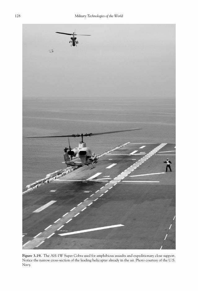
128 Military Technologies of the World
Figure 3.19. The AH-1W Super Cobra used for amphibious assaults and expeditionary close support.Notice the narrow cross-section of the leading helicopter already in the air. Photo courtesy of the U.S.Navy.

129Helicopter Force
Figure 3.20. The CH-53E Super Stallion. Photo courtesy of the U.S. Navy.
Figure 3.21. Cockpit of the Super Stallion helicopter. Photo courtesy of the U.S. Navy.

130 Military Technologies of the World
The MH-53 Sea Dragon is shown in Fig. 3.22,dragging a sled-like hydrofoil antimagnetic ve-hicle with an Mk 104 acoustic minesweepinggear. The MH-53E is based on the Sea Stallionairframe and is the U.S. Navy’s largest helicop-ter with bigger fuel and load capacity. Sea Drag-ons are used for air-to-air refueling of otherhelicopters, internal/external cargo transport,or any other mission requiring heavy loads. TheSea Dragon, if used for the latter purposes, cantransport either fi fty-fi ve fully armed troops or a16-ton payload over 50 nautical miles (nm) ora 10-ton payload over 500 nm.
A unique twin-rotor design is found on theV-22 Osprey (Fig. 3.24) used by various branchesof the military including the special forces.
Osprey is a so-called tilt-rotor aircraft with vertical take-off and landing (VTOL) capa-bilities, with the rotor being tilted to upright position during take-off, landing, or hover.The alignment of the rotors with the aircraft motion allows higher speed and better fueleffi ciency, thus combining the virtues of helicopter and airplane. As the fi rst full-produc-tion tilt-rotor aircraft, the V-22s endured a long, over-the-budget development history,with entrance to the service in 2005. The complexities in the tilt-rotor aircraft emergedduring the development period. Many of the aircraft and engine operation parameters arecontrolled by sensors and an onboard computer that sends commands to the control sur-faces and the engine. Uncommanded engine acceleration occurred due to a glitch in thehardware wiring to the digital engine control, which caused the aircraft to take off duringengine idle. The stability of the aircraft is also sensitive to the computer commands, and afaulty chip or software could cause the aircraft to lose control, which of course had to beeradicated during development. Some of the hardware corrections included leakage fromthe gearbox that could cause engine fi re and malfunction. Compressor fl ow conditionswere at times unstable which also had to be engineered back to design operations. Com-pressor blades operate at the fl uid dynamic level much like an airfoil, with the motion ofthe blade creating a pressure difference across the compressor stage. If the incident fl owmagnitude or the angle is mismatched with the blade orientation, a compressor surge orstall (like airplanes stall at high angles of attack) can occur, leading to loss of enginepower. The fl ow speed, angle, and uniformity therefore must be ensured using a combina-tion of the modifi cations in the engine inlet and compressor inlet guide vanes.
The photograph in Fig. 3.24 shows the Osprey during take-off. The V-22 is a multipur-pose aircraft with the Marines using it for troop and material transport to assault areas, theAir Force for long-range special operations in the CV-22 version, and the Navy for searchand rescue and logistic transports in the HV-22 version. The Osprey is a much larger air-craft than previous helicopters described and can carry up to thirty-two troops or 10,000pounds of cargo plus the two pilots. It has a wing span of 46 feet plus rotors of 38 feet indiameter. The tilt-rotor design allows higher speed than conventional rotorcrafts (316mph), and also longer range (1011 miles).
The Boeing CH-47 Chinook is a classic helicopter, much like the UH-1 Huey, goingback to the Vietnam War ear, except Chinook still remains in service as a large-capacity,heavy-lift helicopter. The tandem, counter-rotating blades are torque-balanced withoutthe need for side-force rotors. Various turboshaft engines have been used on the CH-47,with up to 4500-hp output each (Lycoming L-712). As shown in Fig. 3.25, the Chinook is
Figure 3.22. An MH-53E Sea Dragon retrieving anAN/AQS-14A side-looking sonar.
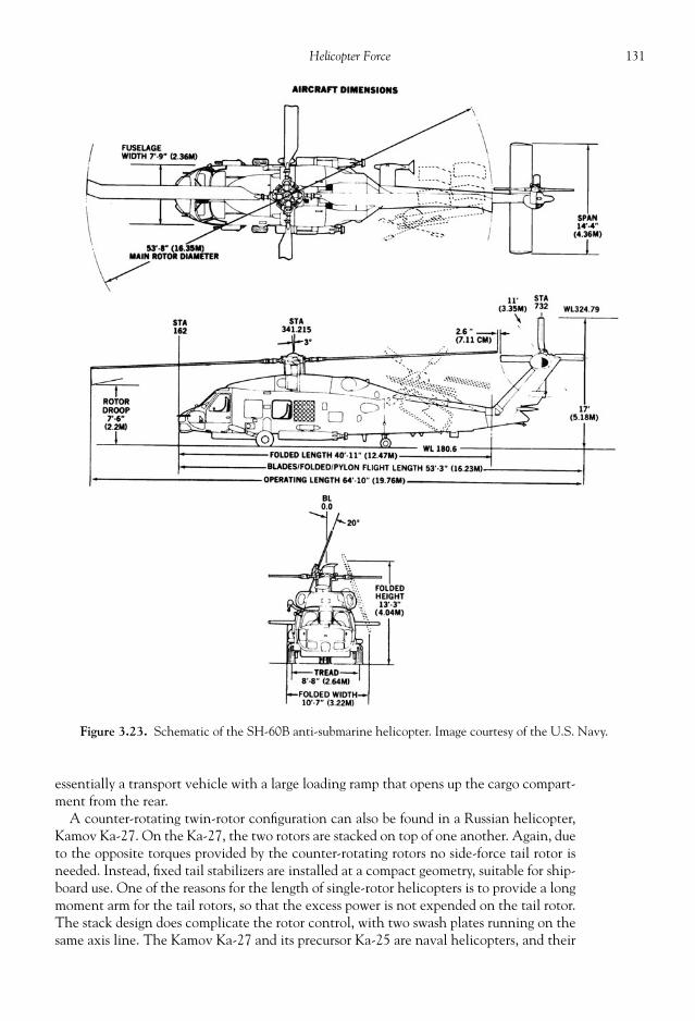
131Helicopter Force
essentially a transport vehicle with a large loading ramp that opens up the cargo compart-ment from the rear.
A counter-rotating twin-rotor confi guration can also be found in a Russian helicopter,Kamov Ka-27. On the Ka-27, the two rotors are stacked on top of one another. Again, dueto the opposite torques provided by the counter-rotating rotors no side-force tail rotor isneeded. Instead, fi xed tail stabilizers are installed at a compact geometry, suitable for ship-board use. One of the reasons for the length of single-rotor helicopters is to provide a longmoment arm for the tail rotors, so that the excess power is not expended on the tail rotor.The stack design does complicate the rotor control, with two swash plates running on thesame axis line. The Kamov Ka-27 and its precursor Ka-25 are naval helicopters, and their
Figure 3.23. Schematic of the SH-60B anti-submarine helicopter. Image courtesy of the U.S. Navy.

132 Military Technologies of the World
uses include anti-submarine attacks using conventionaland nuclear depth charges. Anti-submarine torpedoes,both standard and wire-guided, are also carried. In addi-tion to the radar, Ka-27 can drop a sonobuoy to monitorunderwater activities. A modern Kamov helicopter, theKa-50 Black Shark, serves as the Russian Air Force’smain anti-tank attack helicopter. Although there is atwo-seater version of the Ka-50, the baseline design isthe classic co-axial counter-rotating double-rotor with asingle crew, both aspects of which are unique in an attackhelicopter. It is primarily manufactured by the RussianKamov design bureau; however, in an interesting twist ofmilitary technology transfer Israeli Air Industries also
produces a modifi ed tandem two-seat version of the Ka-50 designated as the Ka-50-2Erdogan.
The philosophy of the Ka-50 design emerged from the Russian experience in the Af-ghanistan confl ict. The mission profi le called for a low-level fl ight to the target area and aclimb up for target acquisition and missile launch which in principle can be handled by asingle crew. The single-crew arrangement allows for the entire aircraft to be smaller,lighter, and therefore more agile and effi cient. The absence of the tail rotor also rendershigher maneuverability for the Black Shark. The twin-rotor design means that thrust canbe generated with smaller-diameter rotors, which delivers an advantage of higher air speed.The maximum air speed of helicopters is limited by the velocity difference between the
Figure 3.24. U.S. Air Force CV-22 Osprey during take-off. The light refraction from the hot engine exhaustis visible. Photo courtesy of the U.S. Air Force.
Figure 3.25. The Boeing CH-47 Chinookhelicopter. Photo courtesy of the U.S. Army.

133Helicopter Force
relative air speed toward the rotor and the rotor speed, as shown in the fi gure below. Be-cause of the opposite directions of the relative air speed toward the helicopter and thespeed of the rotor on the far side in counterclockwise rotations, the velocities actually addup to a higher value. For the rotor, the highest speed is found at the rotor tip, because forsolid body rotation at a given rpm the linear velocity is proportional to the radius. There-fore, the relative velocity between the air and the rotor speed can exceed the speed ofsound long before the helicopter reaches that sonic barrier. For the rotor blade designed tooperate in the subsonic (less than the speed of sound), signifi cant problems occur whenthe relative velocity approaches sonic speed with loss in lift and big increases in the drag.This is a fundamental limitation of the propeller-driven aircraft, but more severe for heli-copters for the above reason. Thus, shorter-radius rotors are advantageous in achievinghigher speeds in helicopters.
The Ka-50 carries up to twelve laser-guided Vikhr anti-tank missiles that have an im-pressive range of 10 km. The target acquisition and missile controls are advanced, withtarget sharing between helicopters, and target data can also be fed by an advance groundscout. A 30-mm Shipunov 2A42 cannon is mounted almost rigidly with relatively smallazimuth or elevation range, but the maneuverability of the aircraft makes up for the lackof aiming control on the cannon. Other armaments include Vympel R-73 missiles, S-8rockets pods, S-13 rocket pods, and up to four 1100-lb bombs.
Another series of Russian helicopters, made by the Mil Moscow Helicopter Plant, fol-low Mi- designations. The Mil helicopter plant was founded by a fellow named MikhailLentyevich Mil and started as Mil Experimental Design Bureau in 1948. A series of mili-tary and civilian helicopter designs emerged from Mil that included attack helicoptersMi-24, Mi-25, and Mi-28. In the Mi-28 helicopters, fi ve-blade rotor design is used withtwo Isotov turboshaft engines with power output up to 2200 horsepower each. The twoengines are mounted on the side close the rotor base, similar to the Apache design. Thegunner and pilots sit in tandem in stepped cockpits. The empty weight of the Mi-28 isestimated at 15,000 pounds and thus is heavier than an empty Apache, but the grossweight is similar at 20,060 pounds. Maximum speed is estimated at 230 mph with a mis-sion radius of 149 miles. Armaments on the Mi-28 can vary from SA-14 air-to-air missilesmodifi ed for helicopter use in a dual-tube launcher, to a quad launcher for AT-6 (anti-tank) Spiral Mod missiles, a UV-32-57 rocket launcher, an updated 30-mm cannon, andFAB-250 bombs. The predecessor to Mi-28 was the Mi-24, with a size and speed charac-teristics of Russian designs. Bulk and speed over maneuverability appears to have been thephilosophy of Russian military engineering. Two Isotov TV-3-117–class turboshaft engineswith 2200 horsepower each lifted the Mi-24 with a maximum takeoff weight of 24,250pounds. The Mi-24 had a cruising speed of 180 mph, in comparison to, for example, 135mph for the Bell UH-1. Mi-24 versions from A to G have been manufactured. Althoughdurable and well-armored, Mi-24’s size (52 ft length by 21 ft height) along with lack ofmaneuverability emerged as its shortcomings during the Afghanistan engagements by theRussians. They were large, exposed targets against shoulder-launched missiles and evenrocket-propelled grenades fi red from short distances. Some Mi-24 helicopters are alsoknown to have crashed during high-G maneuvers, which inevitably seems to occur duringbattle situations, when the rotors broke off under high stress and tore into the fuselage.
In Europe, aerospace industry is consolidated in a four-nation consortium called theEuropean Aeronautics Defence and Space (EADS), with the subsidiary Eurocopter pro-ducing helicopters and Airbus manufacturing military and civilian fi xed-wing aircrafts. Amajor attack helicopter made helicopter is the “Tiger,” introduced in 1991 and used byvarious European military branches. Tiger bears a resemblance to the Russian Mi-28, withtandem, stepped cockpits and two outboard engines. Tiger helicopters are used for multi-role

134 Military Technologies of the World
attack and armed reconnaissance purposes by the German, Spanish, and French armies.Various engine and weapons combinations have been installed in different versions (e.g.,Tiger ARH for armed reconnaissance with upgraded MTR 390 engines, Strix laser targetdesignator, Hellfi re missiles and M299 smart launchers, HAD version for combat supportarmed with Rafael-Spike missiles and Mistral AAM, HAC version for anti-tank attacks).Like its counterparts from the United States and Russia, Tiger helicopters come with ad-vanced electronics and armaments. The TADS/PNVS (target acquisition/designation sys-tem and pilot’s night vision sensor) module includes the Osiris vision system mounted atthe top of the rotor mast and nose-mounted laser rangefi nder and FLIR with a wide-angleview. The basic armaments are a 30-mm AM-30781 cannon, two twenty-two-tube 68-mmrocket launchers, and four Mistral AAMs.
The light weight of the helicopter owes to the advanced materials used in the airframe,such as the Kevlar and carbon laminate frames, panels made with Nomex honeycomb, andthe skin again made with Kevlar and carbon composites. The rotor blade material is high-strength fi ber composite. Kevlar is a synthetic fi brous compound produced by DuPont. Itslight weight and extreme strength make it a highly desirable material for military andaerospace applications. Some of the protective shields in helicopters are made with Kev-lar, as are some of the major airframe components in helicopters as noted above.
HIGH-STRENGTH MATERIALS FOR MODERN HELICOPTERS
Kevlar, mentioned above, is produced by synthesizing two chemical compounds instrong acids, which form chemical structures with multiple inter-chain bonds betweenbenzene rings surround by oxygen, hydrogen, and nitrogen atoms. Its strength-to-weightratio is about fi ve times that of steel. Kevlar has other advantageous properties such as re-sistance to degradation, to extreme temperatures, and of course to extreme external forces.Composite materials are, as the name suggests, a combination of two or more materialsthat results in improved material properties. Reinforced concrete with metal skeletons andconcrete fi lls can be considered as an example of composite materials, although for aero-space applications lighter, higher-strength combinations are used. In composite materials,the matrix and reinforcement materials are combined to produce lightweight, high-strengthcomponents. In carbon composites (sometimes referred to as carbon fi ber reinforced com-posite materials), for example, carbon fi ber fi lament serves as the reinforcement whileplastic material serves as the matrix that adds form for the fi nal shape. The plastic matrixmaterial can vary from epoxy, to polyester, vinyl ester, and others. The carbon compositesexhibit high strength, low weight, an ability to tailor the composite layers (of matrix andreinforcements), high stiffness, and resistance to corrosion and fatigue. Composite materi-als, however, have a tendency to crack under severe loads, and that limits their use incritical structural components yet. The production requires layering of carbon fi lamentsheets, sometimes manually, and then curing the resin material, which is expensive andtime consuming, leading to the high cost of the material and limited use.
The fi ber or the reinforcement material provide the strength and stiffness but by them-selves are brittle in the sense that over-stretching these materials leads to failures, in con-trast to metals which undergo strain or elongations before failure. This is the reason thematrix or plastic materials are combined with fi bers that are layered in multiple directions.If the fi ber material is carbon, then the material is called carbon composites. Anothercheaper fi ber material that is used more ubiquitously is the glass fi bers, which are represen-tative of fi ber materials in that they exhibit stiffness and high strength in the longitudinaldirection but are subject to breaking when pressed in the normal direction. Composites

135Helicopter Force
made with glass fi bers are naturally called “fi berglass,” used in boats, bathtubs, sports equip-ment, and many other daily applications. Other fi ber materials are Kevlar, graphite, boron,and so forth.
The matrix material functions are holding the fi bers in the proper position, transferringthe loads between the fi bers, and providing strength between the fi ber layers. The matrixmaterial is also selected for resistance to heat, chemicals, and moisture depending on theapplications. Matrix materials are essentially plastics such as polyester, vinyl ester, epoxies,polymides, phenolics, and others. As with most plastics, matrix materials noted above willbe in liquid or liquid-like states at high temperatures, and this allows for easy shaping of thecomposite components but also sets the limit on allowable temperature range during use.
Once the fi ber and matrix material is selected, then they can be fabricated into varioushelicopter or other components. The fi bers typically are supplied in woven fabric forms,much like clothing materials. Some woven fi ber fabrics are even pre-impregnated with thematrix resin materials in what are known in the industry as “prepregs.” To form the fi nalshape, the prepregs or fabric plus the resins are layered on a pre-form die and typicallyplaced in a curing chamber called an autoclave. The autoclave applies electrical heat tomelt the resin material so that they will follow the pattern in the pre-form die, and alsohigh-pressure gas presses the composite layers against the die for faithful reconstruction ofthe shape.
A BRIEF HISTORY OF HELICOPTER FLIGHT
The level of technology embedded in modern helicopters is in sharp contrast to themodest beginning of the early helicopter developments. The success of the fi xed-wing air-craft is marked with distinct achievements, most notably the fi rst controlled fl ight by theWright brothers in 1903. There were some fundamental diffi culties with successful helicop-ter fl ights in roughly the same periods. First, the power required for a vertical fl ight, as ischaracteristic of helicopters, is much higher than that for airplanes. The reason is that thevertical lift is provided by the fi xed wings in airplanes, which increases as the velocitysquared. Thus, if the engine generates suffi cient power to overcome the horizontal aerody-namic drag, then eventually the airplane speed will increase to a level necessary to producehigh enough lift force. For vertical fl ight, the engine must produce the lift equal to or greaterthan the helicopter weight, which invariably is much larger than the aerodynamic drag. Ifa larger engine is used, of course that simply adds to the overall helicopter weight defeatingthe effort to overcome the weight problem to begin with. Second, rotating wings on heli-copters produce torque, or a tendency to spin the rotorcraft, and methods to counter thistorque took some time to mature. Another challenge was neutralizing the different liftgenerated on the two halves of the rotors. The rotor blade moving into the direction of thefl ight sees a higher relative velocity than the blade on the other side which is moving inthe opposite direction during a circular rotation. This difference in the relative velocityresults in different lift making the overall rotor lift unbalanced, and therefore the helicop-ter is intrinsically unstable. In addition, large rotor blades rotating at high speeds invariablyled to vibrations threatening the integrity of light construction of early helicopters.
After miscellaneous attempts mostly by European and American inventors and engi-neers from 1907 to 1930, rotorcraft fl ights with human control started becoming success-ful in the 1930s. An Italian, Corradino d’Ascanio, constructed a coaxial, counter-rotatingtwo-rotor helicopter, overcoming the torque problem. A crude pitch control of the rotorswas accomplished by tabs attached to the trailing edge of the rotors that were controlledby cables and pulleys. It was a collective control, with all of the pitches changing by the

136 Military Technologies of the World
same amount, and additional small rotors were used for roll and yaw controls. An Amer-ican design by Maitland Bleeker used a similar mechanism called “stabovators.” Thed’Ascanio coaxial two-rotor design was also used by French aviation pioneers Louis Breg-uet (whose name is borne on some of the French Breguet Aviation and later “AvionsMarcel Dassault-Breguet Aviation” aircraft) and Rene Dorand, who introduced the useof swash plates so that the pitch could be cyclically controlled for pitch and roll move-ments. Their design achieved a range of twenty-seven miles and an endurance of sixty-two minutes. Helicopter development accelerated due to the industrial and militaryprowess of Nazi Germany in the 1940s. Focke-Wulf Company and Weir Company pro-duced a series of capable helicopters during the early 1940s, with the Weir W-5 coaxialhelicopter achieving a top speed of 75 mph. Another design by German engineer An-toine Flettner used an intermeshing rotor confi guration known as the “synchropter” dueto the synchronization of the two rotors to avoid rotor collision. A Russian émigré toUnited States, Igor Sikorsky, pushed along the helicopter developments in the UnitedStates during this period. Sikorsky remains a major helicopter manufacturer, with a num-ber of notable military helicopters: the Sikorsky RH-53 Sea Stallion, CH-53E SuperStallion, UH-60A Black Hawk, and SH-60F Seahawk, along with many others in itscontinuous history.
Soon production of helicopters was being accomplished in both the military and civil-ian sectors, with other manufacturers like Bell Helicopters, Kaman Aerospace, Boeing(originally Vertol) Helicopters, Hughes Aerospace, and McDonnell Douglas Helicoptersfi nding their share of the market in the United States. Now, it is estimated that there areclose to 50,000 helicopters worldwide, and military versions serve as essential vehicles formilitary transport, battlefi eld command and control, reconnaissance, assault, and navaloperations in the military sector. Civilian use is no less important with wide uses in airambulance, search and rescue, agricultural spraying, fi re fi ghting, crime fi ghting, and cor-porate transports.
NAVAL HELICOPTER OPERATIONS
Although not as publicized as the over-land uses, helicopters perform important func-tions during naval operations as well, including anti-submarine warfare (ASW), anti-shipwarfare, missile and artillery targeting, amphibious assault and transport, search and res-cue, minesweeping, airborne reconnaissance, and early warning and transport of troops/materials. Helicopters have the distinct advantage of the vertical take-off and landing,and thus airborne missions can be launched in helicopter-launch surface ships that aremuch smaller than full aircraft carriers. Amphibious naval vessels, for example, can bebuilt and operated at much lower cost and give versatile landing capabilities with helicop-ters providing close-in air support.
Helicopters are well suited for operations like anti-submarine warfare, due to hover andvertical landing capabilities, so that they can deploy submerged, wire-linked sonar andsweep an area at low speeds and can take off and land on small naval vessels. Anti-submarinewarfare, however, involves large areas, and they tend to involve a task force of fi xed-wingaircraft and naval vessels as well as helicopters. The ASW starts from the detection andpositive identifi cation of the opposing submarine. Radars, magnetic detectors, and sonarare the principle methods for detection. Conventional radars can only register signals fromsurfaced submarines and are of limited use with modern submarines, particularly nuclear-powered ones, having long durations of underwater operations. The magnetic detectorslook for anomaly in the earth’s magnetic fi elds and are thus called MAD, for magnetic

137Helicopter Force
anomaly detectors. Submarines are relatively large, metal objects that distort the normalmagnetic fi eld by small, but measurable amounts (typically 1 part out of 10,000). In addi-tion, the earth’s magnetic fi eld itself is not uniform, and detailed mapping of the baselinemagnetic fi eld exerted by the earth is one important segment of the vast amounts of ocean-ographic data amassed by the United States and other navies. MAD modules are func-tional when placed as close to the ocean surface, and for that reason they are typicallydragged by the helicopter at reduced speeds. Also, MAD has a limited range because itmeasures the columnar magnetic fi eld change from the ocean surface to the bottom. MADsensors involve nuclear magnetic resonance (NMR), the same method used for medicalimaging. NMR is a process in which the energy of electromagnetic waves at radio frequen-cies is absorbed by the atomic nuclei at the spin resonant frequencies under a preset mag-netic fi eld. Any alterations in the magnetic fi eld, in this case due to the presence of asubmarine that alters the earth’s magnetic fi eld, subdues the resonance effect, which canbe detected by the change in the amount of radio wave energy absorbed. This NMR sensoris housed in a fi berglass casing that looks like a bomb with a conical opening at the endand hung from the helicopter at a height as close to the ocean surface as possible. Somestand-off distance is required as the helicopter itself may cause fl uctuations in the mag-netic fi eld. In some advanced MAD sensors, the helicopter’s magnetic infl uence is shieldedor digitally compensated so that MAD probe can be operated without having to leave thehelicopter.
Sonar is a powerful sensor in incompressible fl uids like the water in the ocean. Althoughsound propagates in air, the speed of sound is 344 m/s at 21 oC and sound energy tends toget attenuated over some distance. In contrast, the speed of sound in water is approxi-mately 1500 m/s, depending on the temperature and salinity. The attenuation in air istypically around 50 dB/km, while in water it is below 0.1 dB/km which varies somewhatdepending the sound frequency. So the range of sound detection at least 500 times greaterin water, and even higher if one accounts for some particular effects like deep channelpropagation. Like the radars, both passive and active sonar can be used, with the lattergenerating a pulsed sound wave and “listening” to all the refl ected signals including thosepossible from submarines. For helicopter ASW, sonobuoys can be dropped on the surface,or dunking sonar can be dragged with a wire link back up to the chopper. More powerfulship-based sonar can be linked to helicopter weapon systems for guiding anti-submarinearmaments. A photograph shows a U.S. Navy MH-53E Sea Dragon retrieving an AN/AQS-14A side-looking sonar. Sonobuoys are oblong tubes that release the hydrophoneassembly to a preset depth. The hydrophone assembly consists of a super-sensitive micro-phone listening in the audible range of 10 to 24 kHz and beyond and transmitting theacoustic signals through a cable to the VHF antenna that is fl oating on the surface. Be-cause dunking sonar is retrievable, they tend to be more sophisticated and sensitive witharray of hydrophones and also echo (ping) sounders.
A utility helicopter in the naval operations is the H-60 Seahawk series, equivalent tothe Army’s UH-60 Black Hawk. The naval helicopters are typically given the designationSH-60, with other versions such as HH indicating search and rescue, MH for multi-mission, and CH for transport. A schematic of the SH-60B is shown below. The ASWSH-60 carries a bigger load, weighing over 20,000 pounds fully loaded. The Navy versionsalso come with rotor brake and electric power folding of the main rotors, both due to lim-ited space on naval vessels and possible high wind conditions. Some of the anti-submarineand anti-ship weapons and sensors carried by the SH-60 are the Penguin Mk-2 Mod anti-ship missile, the BAe Sea Skua anti-ship missile, the Mk 36 mine, the Mk 53 depth bomb,the Mk 46 anti-submarine torpedo, the Mk50 advanced lightweight torpedo, the AGM-84Harpoon cruise missile, the ASQ-81 MAD towed module, the Bendix AQS-13F dipping

138 Military Technologies of the World
sonar sensor, and the Spartan dwarf DIFAR sonobuoys. ASW capabilities are also installedon the Sikorsky SH-3 Sea King, introduced in 1961 but still in active service with mod-ernized sensors and ASW weapons. The Sea King carries a crew of two pilots plus twoASW operators for the various sonobuoys and Mk 46/44 torpedoes. A B-57 nuclear depthcharge can also be deployed from the Sea King helicopter.
REFERENCES
Bradin, James W. From Hot Air to Hellfi re, The History of Army Attack Aviation . New York: Presidio,1994.
Gunson, Bill, and Mike Spick. Modern Fighting Helicopters. Baltimore, MD: Salamander Books,1986.
Leishman, J.G. Principles of Helicopter Aerodynamics New York: Cambridge University Press, 2000.

THE IMPORTANCE OF intelligence and the need to protect against intelligence (coun-terintelligence) have always been well noted in the minds of successful military leaders.Written in sixth century BCE , the “Art of War” by a Chinese scholar of military affairsnamed Sun Tzu contains several succinct but meaningful quotations such as “All warfare isbased on deception,” and “If you know both yourself and your enemy, you will come out ofone hundred battles with one hundred victories.” The history of war and its generals isfi lled with statements following the same approach to intelligence. “No war can be con-ducted successfully without early and good intelligence” (Duke of Marlborough). “Thenecessity of procuring good intelligence is apparent and need not be further argued” (GeorgeWashington). Alexander the Great relied on the locals throughout his campaign into theMiddle East and Asia to learn of the size of the population, strategic routes, defensible ter-rains, sources of water and food, and strength of the opposing armies. His approach to mak-ing sure that the intelligence data he was getting was accurate was simple and straightforward.For useful and correct information, he rewarded the informant with gold and other riches,of which he had plentiful. For those with false information, he ordered them killed.
With technological advances in stealth and surveillance, the methods with which intelli-gence is obtained and hidden have changed, but some of the principles of military intelligenceremain the same. The intelligence still can be acquired through human or signal intelligence,delivered to the user, validated and interpreted, and fi nally implemented in the battle plan. Inspite of the emphasis on technological intelligence, which is the signal intelligence to bediscussed in this chapter, the human factor in intelligence should not be overlooked. Noamount of visual or signal information can delve into the knowledge and intricacies of humanminds, nor can it exceed the capabilities of human observation and judgments based on signalinformation. Technology is an instrument, and that instrument needs to be used with goodjudgment and purpose by humans. Although technology is studied and appreciated in thisbook, and humans create and benefi t from technology, central military functions will alwaysevolve around well-trained, dedicated people aided by technological gadgets.
The Gulf War during 1990 to 1991, or Operation Desert Storm, may be considered asan example of a successful synthesis of technology with overall war strategy. Data based on
CHAPTER
4
STEALTH,INTELLIGENCE,
AND SURVEILLANCETECHNOLOGY
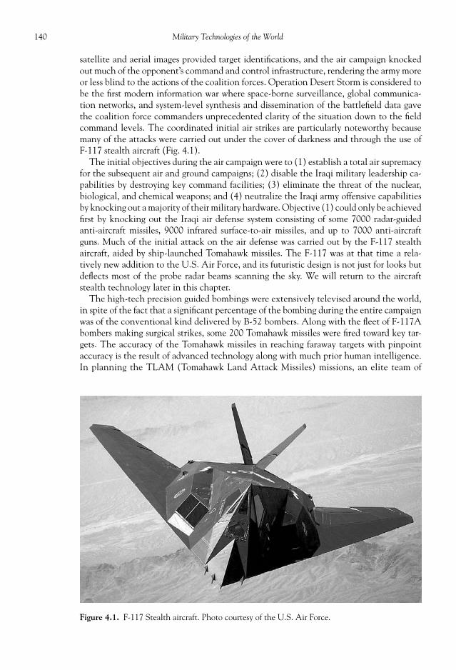
140 Military Technologies of the World
satellite and aerial images provided target identifi cations, and the air campaign knockedout much of the opponent’s command and control infrastructure, rendering the army moreor less blind to the actions of the coalition forces. Operation Desert Storm is considered tobe the fi rst modern information war where space-borne surveillance, global communica-tion networks, and system-level synthesis and dissemination of the battlefi eld data gavethe coalition force commanders unprecedented clarity of the situation down to the fi eldcommand levels. The coordinated initial air strikes are particularly noteworthy becausemany of the attacks were carried out under the cover of darkness and through the use ofF-117 stealth aircraft (Fig. 4.1).
The initial objectives during the air campaign were to (1) establish a total air supremacyfor the subsequent air and ground campaigns; (2) disable the Iraqi military leadership ca-pabilities by destroying key command facilities; (3) eliminate the threat of the nuclear,biological, and chemical weapons; and (4) neutralize the Iraqi army offensive capabilitiesby knocking out a majority of their military hardware. Objective (1) could only be achievedfi rst by knocking out the Iraqi air defense system consisting of some 7000 radar-guidedanti-aircraft missiles, 9000 infrared surface-to-air missiles, and up to 7000 anti-aircraftguns. Much of the initial attack on the air defense was carried out by the F-117 stealthaircraft, aided by ship-launched Tomahawk missiles. The F-117 was at that time a rela-tively new addition to the U.S. Air Force, and its futuristic design is not just for looks butdefl ects most of the probe radar beams scanning the sky. We will return to the aircraftstealth technology later in this chapter.
The high-tech precision guided bombings were extensively televised around the world,in spite of the fact that a signifi cant percentage of the bombing during the entire campaignwas of the conventional kind delivered by B-52 bombers. Along with the fl eet of F-117Abombers making surgical strikes, some 200 Tomahawk missiles were fi red toward key tar-gets. The accuracy of the Tomahawk missiles in reaching faraway targets with pinpointaccuracy is the result of advanced technology along with much prior human intelligence.In planning the TLAM (Tomahawk Land Attack Missiles) missions, an elite team of
Figure 4.1. F-117 Stealth aircraft. Photo courtesy of the U.S. Air Force.

141Stealth, Intelligence, and Surveillance Technology
specialists from the U.S. Central Command, the Navy, Pentagon, and Raytheon (manu-facturer of TLAMs) worked to carefully draw a list of high-priority targets based on satel-lite and other intelligence data. The target coordinates now needed to be converted toexact path commands for the Tomahawk missiles, because they use a combination of iner-tial guidance, global position system, TERCOM (terrain contour matching), and DSMAC(digital scene matching and correlation) to carry out the mission under all weather, night/day conditions. Tomahawk missiles launched from ships or submarines have an initialfl ight path over water, then they approach the so-called fi rst pre-planned waypoint (FWP)to enter their fl ight phase over land. An onboard contour sensor from that point scans theland terrain below, matches it with the stored data to track a path toward the target. Asthe missile nears the target, the guidance typically switches to DSMAC for refi ned accu-racy. Thus, a successful TLAM mission is a culmination of guidance technology and satel-lite and other airborne intelligence data on enemy targets and terrain and on the airdefense systems.
The next major U.S. military engagements with Iraq beginning in 2003 drew massiveattention and analyses, not so much on the military operation to advance to Baghdad butmore on the pre-war intelligence that served as the justifi cation for the invasion. Thepolitical and diplomatic maneuvers toward war with Iraq were based on intelligence or thepresentation of intelligence on Iraqi possession of weapons of mass destruction and onharboring the elements of the terrorist group, Al-Qaeda. The presentation of intelligenceon these issues and how it convinced the U.S. political leadership and a suffi ciently largefraction of the public into waging a major war is a long, twisted story, perhaps outside thescope of this book. It suffi ces to say that these claims were more or less proven to be inac-curate at best; some speculate they were even compromised by a preconceived notion oragenda by an isolated group of war proponents. It serves as a historical lesson that thepolitical leadership must exercise judgment and establish an absolute mandate based onsound intelligence and interpretations thereof before committing an entire nation andportions of the world to a major fi nancial, military, and human endeavor. Bad intelligenceis self-destructive and obviously is worse than no intelligence at all.
Even the Persian Gulf War of 1991 to dislodge Saddam Hussein from Kuwait had anelement of intelligence failure in that advance warnings of Iraq’s intent were improperlyinterpreted or ignored. A sequence of preventive diplomatic maneuvers would have gonea long way in avoiding a later, fi nancially costly campaign to militarily resolve the situa-tion. An interesting aspect of U.S. intelligence in this series of encounters with the Iraqiarmy is that it has had the best resources in the world to gather military data and was wellaware of the fact that the Iraqi army at the time was the fourth largest in the world with5000 tanks and 7000 armored infantry vehicles along with more battlefi eld helicoptersthan the Royal Air Force. During the Cold War and even up to 1993, much of the U.S.intelligence capability was focused on Russia and the Eastern Bloc nations, amassing dataon bombing targets and military assets of encyclopedic proportions. Perhaps, this timeperiod can be considered as a transition in which U.S. intelligence started to deal withmore diverse threats around the world including regimes with unpredictable intentions. Italso points to the fact that mere accumulation of intelligence data leaves open the chancefor misinterpretations, and the sheer volume of unprocessed data can overwhelm the userwithout proper fi ltering and synthesis of information. Iraq and its leadership certainly hada combined psyche that was not entirely familiar to the United States and other westernintelligence communities.
Technology has given unprecedented advantages to armies that possess it in highlymechanized warfare including the potential use of nuclear weaponry. A large amount ofthe technological resources have been invested to develop capabilities in conventional

142 Military Technologies of the World
and nuclear weapons and defenses. The history, however, is laden with unconventionalguerilla and insurgent warfare, because confl icts between unequal powers tend to persist inclandestine, isolated, and sometimes fanatical forms. Desperate situations tend to bringout desperate actions. The ubiquity of unconventional warfare is simply due to the relativeease and low capital needed to wage it. Known instances of insurgent warfare in ancienttimes are plentiful, including the Jewish “sicarrii’s” who resorted to stabbing Roman le-gionaries and their families in the narrow back streets of Jerusalem and elsewhere. Leninand the Bolsheviks started their uprising as a loose group of partisan soldiers who eventu-ally revolutionized the Russian and the world political landscape. Unconventional warfarehas persisted into recent history, from the North Vietnamese Viet Cong to the Irish Re-publican Army, the Palestine Liberation Organization, and now Al-Qaeda. This is a typeof warfare where technology has less impact unless a completely new genre of intelligencetechnology can be developed and applied to penetrate these highly decentralized and de-mechanized organizations.
SPY SATELLITES
The advantage of having an aerial vehicle or a satellite in orbit to monitor what is on theground has long been realized by military planners. Since 1955, the United States has allo-cated signifi cant resources to develop and use reconnaissance satellites for the purpose ofdetermining the enemy war-making capabilities and intents. During the early years of spysatellites, a rather cumbersome method was used that involved loading fi lms on to thesatellites and recovering them once the missions were completed over the target territory.Nowadays, digital cameras are commonplace and spy satellites use high-resolution CCD(charge-coupled device) digital imaging systems to acquire and transmit images in encodedformats. Through advances in imaging devices, optics, and image analyses, it is believed thatmodern high-resolution imaging satellites achieve a spatial resolution of 10 cm (approxi-mately 4 in) or better, although the satellites have an inherent temporal resolution problem.That is, satellites are limited by how often they can fl y over the target areas, which can beseveral hours or several days depending on their altitudes and trajectories. Details of designand resolution capabilities of modern reconnaissance satellites are classifi ed, and also theimage analysis methods are probably the most sophisticated ones available. It can howeverbe assumed that reconnaissance satellites consist of the super-high-resolution imaging de-vices with advanced optics, solar cells to power the electronics, secure encoded downlinkcommunication modules, and orbit and attitude control boosters, along with stealth devices.A less-than-informative photograph of a spy satellite under construction is shown in Fig. 4.2.
It may be compared with an early spy satellite, theCorona KH-4B, a schematic of which is shown in Fig.4.3. The early Corona satellites had a fi lm canisterinstalled in a recovery vehicle, which jettisoned afterthe mission and returned to earth’s surface for recov-ery. A photograph taken by the Corona KH-4B in Fig.4.4 shows the coarse but discernable features in theimaged area.
The United States and most military powers inthe world operate a fl eet of reconnaissance satellites.The United States is known to be the dominant userof these devices and has several separate agenciesto gather and analyze data through these means.
Figure 4.2. A U.S. reconnaissance satellite,Lacrosse, under construction. Photo from thepublic domain of the U.S. National Reconnais-sance Offi ce.
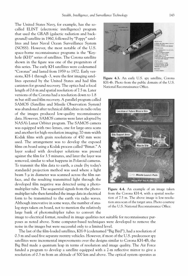
143Stealth, Intelligence, and Surveillance Technology
The United States Navy, for example, has the so-called ELINT (electronic intelligence) programthat used the GRAB (galactic radiation and back-ground) satellite in 1960, followed by “Poppy” satel-lites and later Naval Ocean Surveillance System(NOSS). However, the most notable of the U.S.space-borne reconnaissance programs is the “Key-hole (KH)” series of satellites. The Corona satelliteshown in the fi gure was one of the progenitors ofthis series. The early KH satellites were codenamed“Coronas” and lasted from 1959 to 1972. Early ver-sions, KH-1 through -3, were the fi rst imaging satel-lites operated by the United States and had fi lmcanisters for ground recovery. The optics had a focallength of 0.6 m and spatial resolution of 7.5 m. Laterversions of the Corona had a resolution down to 1.8m but still used fi lm recovery. A parallel program calledSAMOS (Satellite and Missile Observation System)was abandoned after technical diffi culties in radio relayof the images produced low-quality reconnaissancedata. However, SAMOS cameras were later adopted byNASA’s Lunar Orbiter program. The SAMOS camerawas equipped with two lenses, one for large-area scansand another for high-resolution imaging; 70-mm-widthKodak fi lms with grain resolutions of 450 mm wereused. The arrangement was to develop the exposedfi lms on board using a Kodak process called “Bimat.” Alayer soaked with developer solutions was pressedagainst the fi lm for 3.5 minutes, and later the layer wasremoved, similar to what happens in Polaroid cameras.To transmit the fi lm data to earth, a crude (by today’sstandards) projection method was used where a lightbeam 5 μ in diameter was scanned across the fi lm sur-face, and the resulting transmitted light through thedeveloped fi lm negative was detected using a photo-multiplier tube. The sequential signals from the photo-multiplier tube then furnished the image data in electricalform to be transmitted to the earth via radio waves.Although innovative in some ways, the number of ana-log steps taken on board, not to mention the relativelylarge bank of photomultiplier tubes to convert theimage to electrical format, resulted in image qualities not suitable for reconnaissance pur-poses as noted above. Some computer-based techniques were developed to remove thenoise in the images but were successful only to a limited level.
The last of the fi lm-loaded satellites, KH-9 (codenamed “Big Bird”), had a resolution of0.3 m and used fi ve separate reentry vehicles. However, if most of the U.S. predecessor spysatellites were incremental improvements over the designs similar to Corona KH-4B, theBig Bird made a quantum leap in terms of resolution and image quality. The Air Forcefunded a program to develop a satellite equipped with a 2-m refl ective mirror to give aresolution of 0.3 m from an altitude of 500 km and above. The optical system operates as
Figure 4.3. An early U.S. spy satellite, CoronaKH-4b. Photo from the public domain of the U.S.National Reconnaissance Offi ce.
Figure 4.4. An example of an image takenfrom the Corona KH-4, with a spatial resolu-tion of 7.5 m. The above image is low-resolu-tion area scan of the target area. Photo courtesyof the U.S. National Reconnaissance Offi ce.

144 Military Technologies of the World
a Newtonian refl ective telescope, where the 2-m refl ective mirror collects the light, andthe focused light is imaged by the camera. The total weight of this system was 18,000 lbs(about fi ve times the weight of the preceding designs), with a 50 ft length and 10 ft diam-eter. This satellite also had a monopropellant (hydrazine) thruster for orbit maneuversincluding de-orbiting at the end of the mission. The Big Bird satellites were taken intoorbit using Titan III D boosters. Again, because KH-9s were expendable, a series of thesesatellites needed to be launched to maintain the surveillance capabilities, mostly on So-viet ICBM build-up and deployments during this time period. Table 4.1 is a partial list ofthe data on fi lm-loading KH satellites used up to 1972.
After 1976, digital imaging devices became available for use in these satellites. TheKH-11 was the fi rst U.S. reconnaissance satellite using digital imaging and also wasequipped with mirror optics of 2.3 m in diameter. It is believed that the KH-11 is similarin design and dimensions with that of the Hubble Space Telescope that was used for astro-nomical investigations. The Hubble Space Telescope simply turned its optics toward thesky rather than the ground. The initial use of the KH-11 was in 1976, whereas the Hubbletelescope was launched in 1990, so there is a gap of fourteen years before the militarytechnology trickled into the civilian community. The KH-11’s operational altitude was212 miles or 341 kilometers, in comparison to 101 miles (162 km) for the preceding BigBirds (KH-9). In addition to the improved optics provided by TRW Corporation, the useof digital imaging device (charge-coupled device cameras, see below) was at that timerevolutionary. If fi lm loading and development were cumbersome for tourists or daily use,these factors made reconnaissance satellites useless after all the fi lms were used up, in ad-dition to making the entire operation extremely expensive in terms of having to con-stantly launch new satellites and run recovery missions for the fi lm canisters. Digitalimaging allowed the spy satellites to remain operational until other components such asorbit control booster propellants were expended, extending the lifetime of these satellitesto several years as opposed to several months for prior satellites. In addition, recovery ofthe data was no longer a time-consuming affair because the digitized image data could bedownloaded directly to the ground or via an intermediate satellite. As described below,digitized images can be processed and analyzed using computers and this allows the datamining to be highly automated and effi cient. However, due to the limitations in the CCDpixel density the spatial resolution of KH-11 images was only 6 feet! Nowadays, pixeldensity of 5 to 10 million pixels is commonplace; however, at this time fabrication meth-ods were not developed to provide pixel resolutions anywhere close to conventional fi lms.For this reason, KH-11’s were primarily used for area coverage, and KH-9’s were still neededin instances where high-resolution images were required.
The next step up to KH-12 “Ikon” fi nally brought the digital imaging resolution downto 6 inches. This was achieved during the 1980s, so it can be extrapolated that the currentresolving power of U.S. reconnaissance satellites is possibly higher. Ikon operated by trans-mitting the images to the earth in real time, and a fl eet of four or more satellites aroundthe earth provided nearly continuous surveillance of major strategic areas on earth. By thistime, the space shuttle was also available to service the satellites, making their service lifeeven longer. In spite of the important functions performed by these spy satellites, the de-velopment of these devices to the current level of technology was not always devoid ofsetbacks. As noted above, the fi rst set of satellites equipped with digital image devicesproduced images with lower spatial resolution than fi lm counterparts, and also cost over-runs and occasional launch problems brought critics to the forefront of continuing argu-ments between military and civilian spenders. For example, during a launch of the KH-11via the Titan 34 D rocket one of the liquid-propellant engines shut down, resulting in in-suffi cient boost to bring the satellite into orbit. The cost of this mishap: $150 million.

Table 4.1. KH Corona Satellite Data Up to KH-6 (adopted from “Eye in the Sky”).
KH-1CORONA
KH-2CORONA
KH-3CORONA
KH-4CORONA
KH-4ACORONA
KH-4BCORONA
KH-5ARGON
KH-6LANYARD
Period ofOperation
1959–1960 1960–1961 1961–1962 1962–1963 1963–1969 1967–1972 1962–1964 1963
Lifetime 1 day 2–3 days 1–4 days 6–7 days 4–15 days 18 days N/A N/APerigee [nm] 103.5 136.0 117.0 114.0 N/A N/A N/A N/AApogee [nm] 441.0 380.0 136.0 224.0 N/A N/A N/A N/ANumber of Missions 10 10 6 26 52 17 12 3Camera Model C C’ C’’ MURAL J-1 J-3 N/A N/ACamera Type Mono/
panoramicMono/
panoramicMono/
panoramicStereo/
panoramicStereo/
panoramicStereo/
panoramicFrame Panoramic
Scan Angle 70 70 70 70 70 70 N/A 22Lens Tessar f/5 Tessar f/5 Petzval f/3.5 Petzval f/3.5 Petzval f/3.5 Petzval f/3.5 N/A N/AFocal Length [in] 24 24 24 24 24 24 3 66Optical Resolution
(lines/mm)340 340 N/A 480 480 480 N/A 340
Spatial Resolution [ft] 40 25 12 10 9 6 460 4–6Film Type 1213 1221 4404 4404 3404 3404 N/A 3404Film Width [in] 2.10 2.10 2.25 2.25 2.25 2.25 5 5

146 Military Technologies of the World
Also, the Challenger disaster limited the U.S. satellite launch capabilities, and for surveil-lance of strategic weapons a continuous coverage of the key sites is considered essential tomaintain an accurate count and tracking of ICBMs.
The advancement in the KH-series resulted in the KH-13, for which little informationis yet available. It is conjectured that KH-13 has multi-spectral capabilities (that is, sensi-tivity in visible and other wavelength bands such as infrared or possibly radar) along withembedded stealth technology to avoid detection. The optical mirror diameter could be aslarge as 4 m to give a spatial resolution down to 4 cm to discern minute objects on theground. In addition to the most updated imaging technology, KH-13 is believed to havestealth capability to cloak its observational maneuvers.
Many of the other military powers in the world maintain programs in airborne andspace-based surveillance. The former Soviet Union also actively monitored the UnitedStates and NATO nuclear and conventional armament capabilities, using satellites suchas Zenit, Cosmos, Almaz, and Yantar. Similar to the United States, Soviet use of satellitesfor military purposes began in the 1950s. In fact, an offi cer in the military rocket researchinstitute named Mikhail Tikhonravov had the vision of using the rocket technology tosend artifi cial satellites up in earth orbits for ground observations. However, he was de-moted when he submitted an unsolicited proposal for further development of this idea tothe high commands. Only with the support of infl uential high-ranking offi cials was thiswork allowed to proceed, which resulted in authorization for a photo-reconnaissance satel-lite in 1957 for the Soviet Union. A prototype, OD-1, was conceived that was similar indesign to the U.S. counterpart, Corona, with a self-contained camera for later capsule re-covery of the fi lm. During this time, the priority for reconnaissance satellites was not veryhigh in the Soviet military, with the work on lunar and other space probes receiving moreattention in part due to their propaganda values. With the ICBM arsenals rapidly growingin the United States and the Soviet Union, both countries were pressed to determine theICBM production and deployment counts of one another. After much work to developnew technologies, the Zenit-2 was completed by the early 1960s. Zenit-2, unlike the pro-totype OD-1, turned out to be a rather large satellite of 4740 kg, with a length of 5 metersand a diameter of 2.43 meters. This higher weight required larger boosters for Zenit satel-lites, with R-7/8A92 and R-7/11A57 boosters being used for their launches in the 1960s.For the early Corona satellites, smaller Thor-Agena A or Thor–Agena D boosters weresuffi cient. The Soviet engineers opted for designing pressurized chambers for the cameraequipment, as opposed to developing vacuum seal technologies, which contributed to in-creases in the overall weight. Zenit-2 was equipped with four cameras: three 1000-mmfocal length SA-20 cameras and one 200-mm SA-10 camera, where the latter was used forwide-view, low-resolution imaging for location reference purposes. The images from thehigh-resolution cameras taken simultaneously then could be precisely referenced. Thetotal development and testing of the Zenit-2 took nearly two years, from November 1961to October 1963, and paved the way for later Zenit and other Soviet reconnaissance satel-lites such as Cosmos.
Early versions of Cosmos, a series of Soviet reconnaissance satellites, were launched inthe 1960s equipped with cameras and conventional fi lms to be recovered on the groundafter several days of satellite operation in orbit. The Soviets did not have easy access to theocean or the technology for mid-air recovery. Also, the frigid and low-visibility conditionsprevailing in much of the Soviet territory precluded reliable recovery. The Soviet satellitemissions during this period were therefore limited to warm-weather seasons. By the mid-1960s, Soviets regularly launched a cluster of high- and low-resolution satellites to alti-tudes of about 128 miles (205 km) that functioned for eight days or more. It was duringthis time that the United States responded to the Soviet satellite reconnaissance activities

147Stealth, Intelligence, and Surveillance Technology
by monitoring the trajectories of these satellites and alerting the ground bases housingsensitive military equipment to perform anti- or counter-reconnaissance measures and byconcealing or misleading the armament deployment during the satellite passes. One of thedrawbacks of the Cosmos satellites was their relatively short operational lifetime in com-parison to their U.S. counterparts. One estimate has it that the Soviets needed to launchten times as many satellites to have a capability equivalent to the contemporary U.S. spysatellites of the period. An effort made to overcome this drawback was a series of mannedspace missions, better publicized as the “Soyuz” missions referring to the spacecraft thattransported the cosmonauts to the “Salyut” space stations.
Almaz was a manned space station used mostly for military purposes under the guise ofthe civilian “Salyut” orbital space stations. Three Almaz orbiting stations were launchedfrom 1971 to 1978, and due to the excessive cost of launching and maintaining them theformer Soviet Union also reverted to using reconnaissance satellites after 1978. Soyuz iswell known in the western world due to its prolonged use in conjunction with the Salyutstations. The Soyuz spacecraft consisted of the service module containing the rocket en-gines and fuel tanks and the two large solar panels for electrical power. The commandmodule was bell-shaped and was used to bring the cosmonauts back to the earth. So thedesign is quite similar to the Apollo command and service modules during the same era.The major difference between the Soviet and the American space program, of course, wasthat Soviets maintained long-term missions in the space station while the Americans werefocused on sending men to the moon successfully. The Soyuz spacecraft itself has beenused for reconnaissance purposes, with the fi lms moved to the command module prior tothe reentry and brought back to earth. By mid-1980s, the Soviet Soyuz was using radiotransmission to send image data.
Yantar is a series of modern Russian reconnaissance satellites with multi-wavelength ca-pabilities, much like the current U.S. counterparts. The data link was provided by Potokrelay satellites. One major function of these satellites was monitoring of the western ICBMdeployment status for early warning. As the Soviet economy faltered and those of the west-ern alliance thrived with key technologies rapidly being developed, the optical and imagingdevice technology usually lagged behind the Soviet launch capabilities. However, most ofthese technical bugs were removed, and by the mid-1980s the Soviet Union also operated afl eet of modern reconnaissance satellites. Yantar satellites also used the Soyuz launch rocketsand typically operated in the 180 to 280 km range with a mission lifetime up to 259 days.
China’s proximity to the Soviet Union and a constant global standoff with the UnitedStates highly necessitated independent reconnaissance and space programs. Unfortunatelyfor the United States, and fortunately for China, a prominent aerospace engineer namedDr. Chien Hsueh-Sen who worked with Dr. Theodore von Karman at the Caltech JetPropulsion Laboratory, became a victim of McCarthyism during the 1950s. He returned toChina in 1955, led the Chinese space program that initially used the Soviet rocket launch-ers, and made modifi cations and improvements to suit the Chinese needs to counter theU.S. ICBM and other threats (and probably enjoyed every minute of it). By the early1970s, the Chinese started using their ICBM launchers to place rather large reconnais-sance satellites into orbit. The “China 3” satellite that went into orbit in 1975 is believedto carry a television camera and weighed 7718 pounds. A series of “China” satellites fol-lowed. The modern Fanhui Shi Weising (FSW) series of satellites starting in the 1990s areestimated to have modern reconnaissance capabilities, and given the economic and tech-nological growth of this nation the Chinese monitoring capabilities are expect to keeppace with those of their western counterparts.
NATO nations all have or had maintained satellites programs for military purposes, in-cluding the French Helios series, German SAR-Lupe satellites, and British Zircon missions

148 Military Technologies of the World
(cancelled in 1987). Other high-resolution satellites around the world include India’s Tech-nology Experiment Satellite, Iran’s Sinah-1, Israel’s Ofeq, Japan’s Information GatheringSatellite, and South Korea’s “Arirang” series.
The digital cameras used in most imaging devices, including the ones on reconnaissancesatellites, used charge-couple devices. CCDs were fi rst developed as memory-storage de-vices by American scientists Willard Boyle and George E. Smith at AT&T Bell Laboratoryin 1969. CCDs are essentially devices that can hold the electrical charge at a given loca-tion and transfer it in a sequence as a voltage output. For example, if a linear array ofCCDs had an electrical charge sequence of 1, 0, 0, 1, 1, 0, 1 . . . , then that sequence canbe downloaded and read as a voltage signal. Engineers quickly realized that CCDs could becoupled to silicon-based light sensors (photodiodes) to make imaging devices. The lightsensors induce an electrical charge at a location on the CCD that can later be read out insequence to form the distribution of light on the CCD chip, or essentially re-create theimage in an electrical or digital format. This approach of digitizing the image and bypass-ing the fi lm exposure and development has now completely reshaped imaging technology,ranging from fax machines to digital cameras, video cameras, and scanners. For reconnais-sance purposes, this of course meant that the fi lm-loading satellites were now obsolete, andhighly cost-effective imaging satellites could be maintained in orbit and their data down-loaded through a communications link.
Digital image properties can be characterized by the pixel resolution, the intensity distri-bution, and the framing rate. Pixel resolution means the number of pixels on the imagingchip. 1024 × 1024 pixels would give a total of close to 1 million pixels, or 1 “megapixels.”High pixel densities are common in civilian digital cameras, of which there are quite a fewnowadays into 10 megapixels and higher. The fi nal spatial resolution of the imaging systemdepends on both the optics and the pixel density. The intensity is the brightness of thelight signal registered on the imaging chip, and this in turn is digitized using an intensityscale from 1 to 28 = 256, 210 = 1024, etc, where the superscript “8” or “10” is the number ofbits used in the intensity scale. Thus, a 10-bit digitization means that the imaging devicecan discern up to 210 = 1024 levels of “gray” or brightness. The higher the bit number, thefi ner differences in the brightness can be discerned by the camera. Finally, the framing rateis the speed at which images can be acquired. It takes a fi nite amount of time to read outthe pixel data in CCD arrays and reset the pixel voltages, and therefore the framing rate isinversely proportional to the pixel density. However, 1000 frames per second speeds areeasily achieved in modern digital cameras with several millions of pixels or more, and forhighly custom-designed surveillance cameras none of the above camera characteristicspresents a technical hurdle in achieving the necessary performance. The same devices canbe made operational outside the visible wavelength range. Although visible wavelengthsare useful because most optical and imaging devices have been developed to operate in thisrange, one problem is that without sunlight not much is visible in this limited wavelengthrange. However, objects still emit “light” or radiation in the infrared in the absence of ex-ternal illuminations. Infrared imaging devices can therefore be useful under low-light con-ditions, provided that the target objects are at an appreciable temperature above thesurroundings so that their infrared signatures contrast against the surroundings. Anotheruse of the infrared imaging is for night vision, as discussed below.
Once the digital images are acquired and stored in essentially number formats, they canbe processed and analyzed by computers for image enhancements and shape recognition.If the light conditions resulted in weak, the image brightness can be artifi cially increasedby adding to or the multiplying the pixel intensity values. Another result of low lightconditions is low-contrast (small difference between light and dark) images, which againcan be corrected by stretching the intensity distributions in the image. Some of these basic

149Stealth, Intelligence, and Surveillance Technology
functions can be performed on PCs using relative simple programming tools. Of course,the image analysis computers at the national scales use the most sophisticated programsand analysis methods available. Complex patterns, target geometrical shapes, or specifi ctype of motions can be prescribed into the analysis programs to seek these patterns orshapes among millions of images. Some of the noise or resolution limits can even be over-come by applying image enhancement techniques, which essentially are mathematicalapproaches to fi ll in the missing details based on the surrounding pixel data. For militaryand scientifi c purposes, image processing and analysis is a highly developed fi eld.
As noted above, some of the spy satellites employ multi-wavelength detectors to acquireimages in the visible, infrared, or other wavelength ranges. Thus, the use of the satellitesis certainly not limited to the visible wavelengths. In fact, many scientifi c and observa-tional satellites use a large fraction in the electromagnetic spectrum to acquire the desireddata. For example, LANDSAT satellites widely used for monitoring earth resources andland conditions employ seven detection bands: Band 1 (blue-green, 0.45–0.52 �m); Band2 (green, 0.52–0.60 �m); Band 3 (red, 0.63–0.69 �m); Band 4 (near infrared, 0.76–0.90�m); Band 5 (mid-infrared, 1.55–1.75 �m); Band 6 (thermal infrared, 10.40–12.50 �m);and Band 7 (mid-infrared, 2.08–2.35 �m). The reason for using multiple bands or otherelectromagnetic wave bands is simply that different information is contained in the re-spective wavelength bands; also the propagation characteristics through the atmosphereare also different. Since LANDSAT is used for land use analysis, different colors refl ectedfrom different surfaces (ground, tree, urban areas, etc.) register different signals in eachband. Infrared signatures carry information concerning the surface temperature, moisturecontent, or other parameters that can be extracted from the infrared bands. Depending onthe target parameters, detectors operating in the various parts of the electromagnetic wavespectrum can be installed on satellites. This branch of the intelligence is referred to the“electronic intelligence” for the U.S. military and dates back to World War II. ELINToperations can be ground-based, airborne, or performed via satellites. Other componentsof the intelligence follow a similar acronym pattern: HUMINT for human intelligence,COMINT for communication intelligence, SIGINT for signals intelligence, and IMINTfor image intelligence. Using radar signal detectors, for example, ELINT operations mapout the enemy surface-to-air missile guidance radars, command and control centers, orother major hardware exhibiting outgoing radar signals. In addition to the location map-ping, ELINT systems characterize the radar signals for jamming purposes.
The U.S. Navy’s “White Cloud” is a satellite-based ELINT system that tracks the loca-tion and movements of a very large number of military naval vessels. White Cloud oper-ates by recognizing the electromagnetic signals (communications, navigation, radars,weapons control, radars, etc.) emitted by foreign naval vessels and triangulating their posi-tion from a fl eet of satellites designed to pick up these signals. It is used to chart foreignnaval vessel deployment and movements and also to prioritize and program for possibleattack on these targets. To improve accuracy, a group of four satellites is used in synchro-nization. This satellite formation maintains a relative distance of 30 to 240 km, and due tohigh altitudes (approximately 1100 km) and an inclination of over 60 degrees a satellitegroup can monitor a zone with a radius of over 3000 km. The White Cloud program de-ploys suffi cient satellites so that the region between the 40 to 60 degrees latitude can bemonitored over thirty times a day. The ELINT data feed is used in conjunction with imag-ing satellite and other data to map out potential targets well beyond the horizon of operat-ing naval vessels using long-range armaments such as ship-to-ship or cruise missiles. Also,due to their high altitude the ELINT satellites have a long operational lifetime—typicallysix to eight years. Titan IV boosters (shown in Fig. 4.5) are the main launch system usedto place these satellites in high orbits.

150 Military Technologies of the World
NUCLEAR EARLY WARNING SYSTEM
In addition to the global surveillance and intelligence, the United States and Russia alsomaintain a network of ground-based and satellite-based observational platforms to detectpossible launch or launch maneuvers for strategic nuclear weapons. More information on thistopic is given in Chapter 5 (Space Warfare). Due to the high speeds attained by ICBMs andSLBMs, the amount of time available to respond to a nuclear attack is in terms of minutes
Figure 4.5. Launch of a Titan IV-B rocket booster, used to send military satellitesinto orbits. Photo courtesy of the U.S. Air Force.

151Stealth, Intelligence, and Surveillance Technology
(typically twenty-fi ve minutes for ICBMs and fi fteen minutes for SLBMs). This makes itimperative that any potential missile launch events are immediately detected, identifi ed, andcommunicated to the top levels. As nuclear weaponry is in constant danger of being prolifer-ated, the requirements become more severe and expansive to monitor the world for potentialuse of nuclear weapons, particularly through avenues other than the traditional deliverymethods discussed above. The U.S. Strategic Command (STRATCOM) operates a globalmonitoring system for nuclear early warning. A system of radars and satellites along withsatellite image data for deployment maneuvers are networked to accomplish this mission.
The early warning system can trace origin to the 1950s when the United States soughtto build up its air defense against the growth of the Soviet Union’s bomber capabilities. Anetwork of radars called the Distant Early Warning (DEW) was constructed in Canada.Again, even at this early stage the radar sites were linked to a command center which inturn communicated with surface-to-air missile sites and interceptor bases. The DEW wasdesigned for early warning against bomber attacks and therefore was made obsolete by theadvent of the ICBMs. Because the Siberian region of the Soviet Union, for example, wasvery close to the United States, the threat of ICBM attack was real and potentially im-mediate. Work began on the Ballistic Missile Early Warning System, with radar stations inThule (Greenland), Clear (Alaska), and Fylingdales Moor (England). However, theground-based radars could not see beyond the horizon as the radars rely on electromag-netic beams traveling to the target and the refl ected signal returning to the radar site. Thedistance from the radar sites and potential launch locations in the USSR meant that onlyabout fi fteen minutes of warning time would be given assuming that the missiles werecaught by the radar sweeps and correctly identifi ed, which was not a certainty at that time.Thus, the necessity for space-borne early warning satellites was again brought up.
The Midas (Missile Defense Alarm System) satellites were developed to overcome thelimitations of the ground-based radars. Again, a system of satellites, up to eight, was calledfor to provide large-area, near-continuous coverage. Onboard rocket engines on these satel-lites maintained the orbital positions. With this group of satellites in place, the launches inmost parts of the Soviet Union could be detected based on the thermal emission with a prob-ability of 80 percent or higher. Without the infrared imaging camera, not available duringthe early phase of the Midas, the “Aegina” satellites used in the Midas relied on the strongthermal emission of the ICBM boosters that became prominent soon after launch. The sen-sors and the communication link, along with the satellite orbital control rockets, resulted ina 3246-lb module. Midas evolved into later programs for nuclear early warning such asBMEWS (ballistic missile defense early warning system) and IMEWS (integrated missileearly warning system). Currently, the defense support program (DSP) is operated by theUnited States Air Force to provide reconnaissance data for missile early warning includingstrategic nuclear and conventional missile activities. For example, DSP capabilities wereused during Desert Storm operations to detect launches of Iraqi Scud missiles. Modern DSPsatellites are placed in high-altitude geosynchronous orbits and are equipped with infraredsensors coupled with telescope optics. Fig. 4.6 shows an artist’s depiction of a modern DSPsatellite used for missile early warning. The modern DSP satellites operate at orbit altitudesof close to 35,000 km and weigh in excess of 5000 lbs (2380 kg) at a cost of $400 million persatellite. The diameter of the satellite with all of the components extended is 6.7 m.
The integrated strategic early warning system consists of the (1) DSP (defense supportprogram) satellites, as noted above; (2) BMEWS (ballistic missile early warning system)radars; (3) Pave Paws for early warning of sea-launched ballistic missiles; (4) PARCS (pe-rimeter acquisition radar attach characterization system) radar; (5) Cobra Dane phasedarray radar; and (6) conventional radars. Details of some of the above radars can be foundin a later discussion on that subject in this chapter.

152 Military Technologies of the World
SATELLITES AND ORBITAL MECHANICS
In the previous discussions of military satellites, orbital aspects were inevitably included.The operation of placing satellites in earth orbits and beyond requires appropriate rocketboosters and orbit considerations. The heavier the payload and the higher the target alti-tude, the more powerful the rocket boosters would be required to be. However, the term“powerful” in rocketry has several aspects. It is not enough to simply burn more propellantsto generate suffi cient thrust. The maximum velocity attainable by a rocket, and thereforethe maximum altitude, depends on the ratio of the initial and fi nal mass and also on therocket exhaust velocity. The initial mass includes the payload, propellants, and structuralmass of the rocket, and the fi nal mass usually is the payload mass itself. The rocket exhaustvelocity itself depends on many parameters, such as the molecular weight of the propel-lant, rocket combustion chamber pressure and temperature, and the nozzle design. Forexample, the lower the molecular weight of the propellant, the larger the exhaust velocitythat can be generated. This is the reason for the choice of liquid hydrogen for space shuttlemain engines. A large exhaust velocity accomplishes two things: One is that it generatesa large amount of momentum out the nozzle that translates into large thrust force, andtwo, it gets rid of the propellant mass quickly so that the rocket becomes lighter and easierto accelerate. To improve on the mass ratio aspect, staging is often used, which simplyinvolves getting rid of unneeded mass. Jettisoning of the lower stages is staging, as are theliquid propellant tanks and solid rocket boosters being separated from the space shuttleafter their functions are completed during the boost phase.
Consideration of the required kinetic energy to overcome the potential energy of theearth or other gravitation fi eld provides escape velocity. For earth surface launch, a veloc-ity of 11,179 m/s (25,012 mph) would be needed to provide suffi cient kinetic energy toescape the pull of the earth’s gravity. In the moon’s weaker gravitational fi eld (a little lessthan one-sixth of the earth’s), the escape velocity is 2366.22 m/s or 5325.75 mph. How-ever, this is not to mean that a spacecraft must acquire this velocity for outer space travel.Escape velocity is simply an initial velocity with suffi cient kinetic energy to overcome thegravitation fi eld. A spacecraft in principle can go anywhere provided that it can generatemore thrust force than the gravitational force, and of course the latter decreases rather
Figure 4.6. U-2 “Dragon Lady.” Photo courtesy of the U.S. Air Force.

153Stealth, Intelligence, and Surveillance Technology
rapidly with increasing distance from the earth. For earth launch in the eastern direction,the earth rotation adds 914 mph to the rocket speed.
Depending on the north-south direction of the rocket motion, the fi nal orbit aroundthe earth will be different. The angle of the orbit with respect to the equator is called theinclination angle. Since earth’s rotation plane intersects the equator, satellites with a zeroinclination orbit essentially see the same latitude regions close to the equator during theirpasses over the earth. If the inclination angle is 90 degrees, it is called a polar orbit, and asatellite in a polar orbit will see the entire earth as the earth rotates beneath it. To coverthe entire Soviet Union during the Cold War, a majority of the U.S. reconnaissance satel-lites were sent into orbits with 80 to 100o inclination angles in contrast to the 65 to 81o forthe Soviet satellites. Other useful orbits are sun-synchronous orbits (SSO) and geosyn-chronous orbit (GEO). GEO involves sending satellites with a zero inclination angle intorelatively high altitudes where the speed of the satellites coincides with that of the earthrotation so that the satellites appear to be fi xed over the same location. To achieve GEO,the spacecraft is sent to an elliptical orbit with an apogee of 35,785 km (22,236 miles) andthen orbit adjustments are made to circularize the orbit. SSO involves placing the satel-lites in an orbit again with the same rotational speed as that of the earth except the incli-nation angle is not zero. This will result in the satellite path that sweeps different pointson earth at exactly the same local time regardless of the location. The utility of SSO is forobservational methods that depend on solar illumination. If the satellite passes over thelocation at the same local time, then the sun’s angle will be the same at all locations.
The orbital speed is directly related to the altitude. This can be visualized as the momen-tum that is required to maintain an object circling around with a string holding it in. Theobject will keep that circular motion as long as it is rotating fast enough to keep the stringtaut. For shorter string, the speed needs to be faster and vice versa. To get into a little me-chanics, an object rotating at speed of v at a radius of r is subject to a centripetal accelera-tion of v2 /r. Centripetal acceleration is the component of velocity that keeps the object ina circular motion, and in earth’s gravitational fi eld the centripetal acceleration is given bythe gravitational acceleration g = GM/r2 . Here, G is gravitational constant of 6.670 x 10⁻¹¹
m3 /s2 kg and M is the mass of the earth (5.974 × 1024 kg). Equating v2 /r with GM/r2 and thensolving for v, we get v equal to the square root of GM/r. Noting that r represents the dis-tance from the center of earth so that at altitude of 5000 miles gives r = 5000 miles + (earthradius) = 8960 miles. We can run some numbers from this formula. At an altitude of 5000miles, the orbital speed is approximately GM/8960, or 11,765 mph whereas at a 22,236-mile altitude the speed is 6880 mph with a period of 24 hours, therefore resulting in ageosynchronous orbit. The period is obtained by using the radius of 22,236 + (earth radius)= 26,196 miles. 2π times this radius gives the circumference of this orbit, and the circum-ference divided by the orbital speed of 6880 mph gives 24 hours and thus GEO. In orbitalmechanics, the apogee refers to the highest altitude and thus lowest speed in an ellipticalorbit where as the perigee is the lowest altitude and highest orbital speed.
A satellite launch using a Titan IV rocket for a 100 nautical mile (1 nautical mile isabout 1.15 mile) altitude low-earth orbit placement will typically undergo the followingmission sequence:
t = –5 sec, initiate the inertial guidance system. t = –2 sec, stage I ignition signal given. t = 0.0, lift-off. t = 9.0, roll to fl ight azimuth. t = 19 sec, end stage I roll maneuver. t = 20.0 sec, start pitch rate 1.

154 Military Technologies of the World
t = 25.0 sec, drive angle of attack to zero (pitch rate 2). t = 30.0 sec, begin zero lift. t = 110.0 sec, end zero lift, start pitch rate 3. t = 135.0 sec, start pitch rate 4. t = 156.9 sec, end of state I steady-state burn. t = 157.7 sec, stage I separation (80 nautical miles downrange, altitude 35 nautical
miles, velocity 8865 ft/s). t = 161.0 sec, begin linear sine steering. t = 210.9 sec, payload fairing separation (140 nautical miles downrange, altitude 64
nautical miles, velocity 11,123 ft/s). t = 332.8 sec, stage II shutdown (450 nautical miles downrange, altitude 102 nautical
miles, velocity 25,524 ft/s). t = 378.0 sec, converge to commanded attitude, begin velocity trim. t = 406.0 sec, end velocity trim. t = 434.0 sec, start maneuver to payload separation. t = 519.0 sec, payload separation (1200 nautical miles downrange, altitude 100 nautical
miles, velocity 25,677 ft/s).
Space shuttles are also used for placement of satellites, both military and civilian. Thereis a standard sequence for space shuttle missions.
Ignition and lift-off (t = 0 hour, 0 minutes). Roll and initiate pitch. Solid rocket booster separation (t = 0 hour, 2 minutes). Main engine cutoff and external tank separation (t = 0 hours, 8 minutes). Orbit insertion and circularization (t = 0 hours, 45 minutes). Orbiter orientation and verifi cation. Open cargo bay doors, deploy antenna (t = 1 hours, 0 minutes). Orbiter checkout over tracking station (t = 1 hours, 18 minutes). Orbiter checkout over tracking station (t = 2 hours, 53 minutes). Orbiter maneuvers, cargo deplyments (t = 3 hours, 0 minutes).
SPY PLANES
The vantage afforded by height was known to men long before the advent of satellites.The French used manned balloons for reconnaissance and symbolic purposes in 1794.Winged aircraft were used for this purpose in the early 1900s and during World War I, al-though in the latter the reconnaissance missions have been known to degenerate intoairborne pistol duels, giving birth to the aerial dogfi ghts between opposing aircrafts. How-ever, the aircraft that perhaps best symbolizes airborne reconnaissance is the U.S. U-2“Dragon Lady” (shown in Fig. 4.6). The Dragon Lady, made by Lockheed, entered servicein 1955 and is still in service carrying a variety of detection equipment ranging from amulti-spectral imaging camera to electro-optic, infrared, and radar sensors. The main at-tribute of the U-2 is versatility, at the expense of risking piloted missions over enemy ter-ritory. The aircraft can be sent to target locations, make multiple passes, and deployappropriate sensors at arbitrary times. In that sense, aircraft perform surveillance functionsas opposed to reconnaissance. Although the terms “surveillance” and “reconnaissance” areused interchangeably, in military terminology surveillance means sustained observation ofthe events and layouts of a fi xed location while reconnaissance is associated with makinglimited passes over the target location as in satellite reconnaissance.

155Stealth, Intelligence, and Surveillance Technology
The U-2 aircraft as shown in Fig. 4.6 has a high aspect ratio and straight wings that pro-vide glider-like performance at the expense of speeds. The wing design allows for large liftand low drag, and the aircraft weight is kept to a minimum so that fl ight duration and rangeare maximized. The wing area is 1000 square feet, with an empty aircraft weight of 14,900 lb(at take-off with fuel and equipment, the U-2 can weigh up to 41,000 lb). The U-2 has amaximum speed of 510 mph, less than the cruise speed of 567 mph for a commercial Boeing747, but has a range of 11,000 miles or 7.5 hours of fl ight time without refueling. The U-2 isdesigned to operate at high altitudes up to 80,000 feet for sustained periods of time highabove any enemy threats, although the latter aspect has been compromised at least once ina much publicized “U-2 Crisis” in which the aircraft was shot down over Soviet territory in1960. However, under normal conditions U-2 operates at an altitude of 70,000 feet, beyondthe reach of most Soviet aircraft, missiles, or radars. The combination of the light weight,high altitude, and large aspect ratio wing makes the U-2 aircraft diffi cult to fl y, with a smallenvelope of stable fl ight. An estimated thirty-plus U-2 aircraft are operated by the U.S. AirForce, and they have played important roles recently during the confl icts in Iraq and Af-ghanistan and over Bosnia and Kosovo in support of NATO forces. The U-2 can carry amultitude of photographic, electronic, radar, infrared, and air sampling sensors that can beconfi gured for a given mission. A number of electro-optic sensors (digital imaging cameras)of various resolution and fi eld of view are typically simultaneously operated for referencingand identifi cations. ASARS-2 synthetic aperture radar (SAR) is capable of gathering de-tailed ground terrains and objects under night/day, all-weather conditions. This SAR usestwo V-shaped arrays that scan the ground on each side of the aircraft within a range of over100 miles. As opposed to simple two-dimensional pictures generated by the electro-opticalsensors, SAR data are used to build three-dimensional synthetic images of the world belowfor far superior identifi cation of objects (on the ground and in the air) and situational aware-ness. In addition, multiple moving targets can be identifi ed and posed in the synthetic back-ground image. A signal intelligence suite called “Senior Glass” contains extremely sensitiveantennas that monitor the radio and other communications. The intelligence data obtainedfrom the sensors can be sent in real time via satellite-borne uplink routes. For their high-altitude capabilities, the U-2 aircrafts are also used in the ER-2 version by the NASA tocarry sensors to monitor earth resources, atmospheric dynamics and chemistry, ocean dy-namics, and upper-atmosphere physics.
If the U-2 Dragon Lady is the effi cient workhorse that has served useful functions forover fi fty years, then the SR-71 Blackbird is the blazing racehorse version of a spy plane.Its futuristic design and high speed (Mach 3) have made this aircraft the fl agship for ex-hibiting U.S. aerospace technological advances. In fact, many if not most of the designand components to go on the SR-71 represented important advances in high Mach num-ber fl ight technology. In contrast to the subsonic U-2, the Blackbird was powered withPratt & Whitney J-58 afterburning turbojets with a combined thrust of 65,000 poundsalong with a wing-body design to send this aircraft moving at a maximum speed of Mach3.2 (possibly greater). This corresponds to 2200 mph at the aircraft service altitude of80,000 feet (24 km or 15 miles). To put this kind of speed in perspective, the SR-71 wouldrequire only sixty-four minutes to go from New York City to London in comparison to theConcorde fl ight time of three hours and twenty-three minutes and the Boeing 747’s sixhours and fi fteen minutes. Of course, we have to account for the fact the commercial air-liners probably would not accelerate the passengers at the level of the SR-71, thus takinglonger to achieve the maximum fl ight speeds. For some time, the Blackbird was the world’smost advanced aircraft, breaking the records for the highest speed and altitude for its class.The Blackbird’s unclassifi ed maximum speed is 2193 mph and its maximum altitude 85,070feet. The high speed and altitude of the SR-71 made the aircraft impervious to enemythreats. It could simply accelerate or move into a higher altitude to avoid contact with

156 Military Technologies of the World
incoming missiles or aircraft. The SR-71 design also included a fl attened profi le (as shownin the photograph and schematic in Figs. 4.7 and 4.8) to minimize the radar profi le andaerodynamic drag. This is the one of the fi rst attempts at aircraft radar stealth technology.However, due to the uncovered engine exhausts and the vertical stabilizer, the SR-71 ac-tually ended up with a large radar profi le, and civilian radars could track bright spot on thescreen for hundreds of miles. In spite of its impressive performance and looks, the Blackbird
Figure 4.7. The SR-71 Blackbird strategic reconnaissance aircraft. Photos courtesy of the U.S. AirForce.
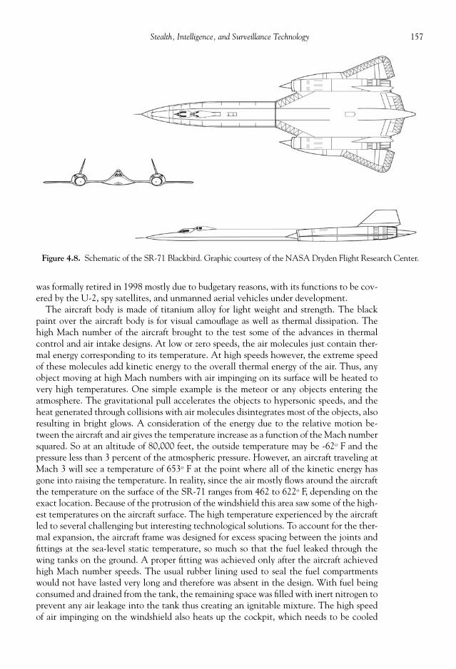
157Stealth, Intelligence, and Surveillance Technology
was formally retired in 1998 mostly due to budgetary reasons, with its functions to be cov-ered by the U-2, spy satellites, and unmanned aerial vehicles under development.
The aircraft body is made of titanium alloy for light weight and strength. The blackpaint over the aircraft body is for visual camoufl age as well as thermal dissipation. Thehigh Mach number of the aircraft brought to the test some of the advances in thermalcontrol and air intake designs. At low or zero speeds, the air molecules just contain ther-mal energy corresponding to its temperature. At high speeds however, the extreme speedof these molecules add kinetic energy to the overall thermal energy of the air. Thus, anyobject moving at high Mach numbers with air impinging on its surface will be heated tovery high temperatures. One simple example is the meteor or any objects entering theatmosphere. The gravitational pull accelerates the objects to hypersonic speeds, and theheat generated through collisions with air molecules disintegrates most of the objects, alsoresulting in bright glows. A consideration of the energy due to the relative motion be-tween the aircraft and air gives the temperature increase as a function of the Mach numbersquared. So at an altitude of 80,000 feet, the outside temperature may be -62o F and thepressure less than 3 percent of the atmospheric pressure. However, an aircraft traveling atMach 3 will see a temperature of 653o F at the point where all of the kinetic energy hasgone into raising the temperature. In reality, since the air mostly fl ows around the aircraftthe temperature on the surface of the SR-71 ranges from 462 to 622o F, depending on theexact location. Because of the protrusion of the windshield this area saw some of the high-est temperatures on the aircraft surface. The high temperature experienced by the aircraftled to several challenging but interesting technological solutions. To account for the ther-mal expansion, the aircraft frame was designed for excess spacing between the joints andfi ttings at the sea-level static temperature, so much so that the fuel leaked through thewing tanks on the ground. A proper fi tting was achieved only after the aircraft achievedhigh Mach number speeds. The usual rubber lining used to seal the fuel compartmentswould not have lasted very long and therefore was absent in the design. With fuel beingconsumed and drained from the tank, the remaining space was fi lled with inert nitrogen toprevent any air leakage into the tank thus creating an ignitable mixture. The high speedof air impinging on the windshield also heats up the cockpit, which needs to be cooled
Figure 4.8. Schematic of the SR-71 Blackbird. Graphic courtesy of the NASA Dryden Flight Research Center.

158 Military Technologies of the World
using an air conditioner that dumps excess heat onto the fuel. Other heat dissipatingschemes were embedded on to the SR-71. The black paint had a higher irradiative emis-sivity than bare metal skins by about a factor of three. At high temperatures the surfaceglowed dark blue, radiating away some of the surface heat. The wing surface also was ma-chined with small longitudinal corrugations, so that thermal expansions do not warp anyof the constituent panels.
The high speed also necessitates a control device to lower the engine intake velocity. Ashock cone visible at the inlet of the turbojet engine creates a shock well ahead of theengine. The air fl ow slows down somewhat while its temperature and pressure again go up.The shock cone travels back and forth along the direction of the engine axis to optimizethis deceleration process at various fl ight Mach numbers. Subsequent shocks that developat the annular region between the shock cone and the engine shroud bring the air speedfurther down so that the main part of the engine sees a subsonic air speed. The speed ofthe incident air also allowed air into the Pratt & Whitney J-58 afterburning turbojetswithout running the air through the compressor-combustor-turbine of the engine (thecore part of the gas-turbine engine). Due to high Mach numbers, the ram compressionelevated the pressure to a substantial level so that only fuel needed to be injected in theafterburner section. This operation is called the ramjet propulsion, and the Blackbird en-gine inlet design allowed for hybrid operation to go to ramjet mode at high Mach numbersand normal turbojet operation at low and intermediate Mach numbers. As noted above,at Mach 3 the outside temperature of –62o F can be raised to 653o F due to the ram effect,while the pressure will go up thirty-six times—this surpasses the pressure increase that gas-turbine compressor can generate. However, control of the shock pattern by moving theshock cone back and forth led to a quirk in fl ying the SR-71. The shock cone movementwas not fast enough to adjust to the increasing speed of the Blackbird, and if the inletcondition was mismatched the engine basically shut down due to a number of events thatcan occur if the inlet pressure is not matched with engine operating conditions (e.g., com-pressor stall, engine fl ame-out). With two engines, one engine shutting down meant asudden spin moment to violently turn the aircraft. This situation was corrected by thevertical fi ns turning to provide an opposite moment while the other engine was deliber-ately shut down. Once the normal aircraft angle was recovered, the both engines were relitto resume the fl ight.
The sensors carried by the Blackbird evolved with digital electronic technology. Origi-nally, relatively simple tracking and surveillance cameras were mounted that operated inthe visible and also in the infrared for nighttime vision with moderate resolution capa-bilities. High resolution cameras that were used on Blackbird later included a stereo-imagingcamera called “Operational Objective Camera (OCC),” which allowed a precise three-dimensional reconstruction of the terrain and objects under the aircraft. Prior to decom-missioning of the Blackbird, an imaging device called “Technical Objective Camera(TEOC)” was used that had a swivel of +/– 45 degrees from the centerline and a spatialresolution of six inches from the Blackbird’s operational altitude of 80,000 feet. With twoTEOC cameras usually carried by the SR-71, high-resolution images of the ground objectswere brought back for analyses, although the satellite imaging capabilities soon caught upwith the level of performance. Side-looking radars (SLR) and synthetic aperture radarsystems (SARS) were also one of the primary surveillance tools carried on the SR-71. Theprinciples and use of the radars are described later in this chapter. In addition, electronicintelligence (ELINT) sensor pods were used on the Blackbird missions, with the sensorprogrammed to pick up particular signals of interest.
Although the Blackbird was retired while the U-2 Dragon Lady remains in service as of2007, the design of the SR-71 Blackbird was conceived as a replacement of the U-2 Dragon

159Stealth, Intelligence, and Surveillance Technology
Lady in anticipation of the U-2s becoming highly vulnerable to the developing Sovietair defense technology. The Lockheed design called at that time A-12 won over theU.S. Navy’s proposed design of using a pure ramjet aircraft to be elevated to operationalaltitude on a balloon and then propelled to supersonic speeds with rocket boosters atwhich time the ramjet would fi re up. The A-12 design with a hybrid engine mounted on amodifi ed XF-104 (an experimental aircraft designed for supersonic speeds) airframe devel-oped into the SR-71. As with many aerospace systems, the development of the hybridengine capable providing enough thrust for the A-12 became the technological bottle-neck, and initial test fl ights of the SR-71 precursors had to be conducted using weaker J-75engines giving a maximum speed of Mach 2 as opposed to Mach 3.2 with the thrust gener-ated by the Pratt & Whitney J-58 engines. Even without the high thrust of the J-58 en-gines, the new design provided some initial excitement during the fi rst test fl ights withwild fl ight instabilities experienced in all three axes and somehow fl own out of by the testpilots. With the J-58 engine fi nally fi tted to the Blackbird, other new issues emerged, suchas the cockpit overheating due to the ram effect. Some of the pilots complained of notbeing able to hold on to the hot control stick and the cockpit area becoming overheated.In spite of these trials, the A-12 design evolved and was designated SR-71 and fl ew over3500 missions, with 53,490 total fl ight hours. Moreover, through collaboration withNASA much scientifi c and engineering knowledge in high-speed aircraft aerodynamics,structure, control, and propulsion was accumulated for use in other military and civilianaircraft developments.
UNMANNED AERIAL VEHICLES FOR SURVEILLANCE
As the name suggests, unmanned aerial vehicles (UAVs) fl y under remote control orfollow pre-programmed paths using onboard or externally linked navigation systems. Be-cause human pilots are not on board, UAVs do not need cockpit and pilot support equip-ment and thus can be made more compact. It can undertake high-risk missions and can beproduced at lower cost and therefore allowed to be expendable. Thus far, most of the UAVuse is military due to high cost and its narrow range of functions. Reconnaissance, surveil-lance, and small-scale attacks can be carried by UAVs. In fact, cruise missiles can be con-sidered as a type of UAV since it delivers munitions under its own propulsion andnavigation, and it is conceivable that larger, more complex bombing missions may be car-ried out by UAVs in the future because more of the navigation and targeting now rely onmachine vision (digital cameras) and onboard computers. Already, the U.S. military pos-sesses and deploys a number of UAVs (see Table 4.2).
The BATMAV (shown in Fig. 4.9) stands for battlefi eld air targeting micro air vehiclesand gives an appearance of a small, remote-controlled model airplane, except it carries aprice tag of about $49,000 as of 2006. As the name suggests, it is used for situational aware-ness in the battlefi eld and target acquisition and directions through the use of a high-resolution camera with nighttime vision capabilities. It has a collapsible airframe for easystorage and transport and runs on an electric motor with rechargeable lithium ion batter-ies (so it could serve as a toy airplane except again for the price tag). The internal globalposition and inertial navigation allows autonomous, programmable fl ights, but it can alsobe piloted using a handheld remote control unit. The wing span is only 42 cm (16.5 in)with a length of 29 cm (11.5 in) and a weight of 6.5 kilograms (14.4 lbs). BATMAVs twin-blade propeller can propel this micro vehicle to a speed of 40 mph.
In Table 4.1, the medium altitude and long endurance (MALE) categorization refers toUAVs with a altitude of up to 30,000 ft and a range over 200 km, while high altitude, long
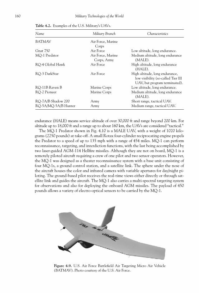
160 Military Technologies of the World
Table 4.2. Examples of the U.S. Military’s UAVs.
Name Military Branch Characteristics
BATMAV Air Force, Marine Corps
Gnat 750 Air Force Low altitude, long endurance.MQ-1 Predator Air Force, Marine
Corps, ArmyMedium altitude, long endurance
(MALE).RQ-4 Global Hawk Air Force High altitude, long endurance
(HALE).RQ-3 DarkStar Air Force High altitude, long endurance,
low visibility (so-called Tier IIIUAV, but program terminated).
RQ-11B Raven B Marine Corps Low altitude, long endurance.RQ-2 Pioneer Marine Corps Medium altitude, long endurance
(MALE).RQ-7A/B Shadow 200 Army Short range, tactical UAV.RQ-5A/MQ-5A/B Hunter Army Medium range, tactical UAV.
Figure 4.9. U.S. Air Force Battlefi eld Air Targeting Micro Air Vehicle(BATMAV). Photo courtesy of the U.S. Air Force.
endurance (HALE) means service altitude of over 30,000 ft and range beyond 200 km. Foraltitude up to 18,000 ft and a range up to about 160 km, the UAVs are considered “tactical.”
The MQ-1 Predator shown in Fig. 4.10 is a MALE UAV, with a weight of 1020 kilo-grams (2250 pounds) at take-off. A small Rotax four-cylinder reciprocating engine propelsthe Predator to a speed of up to 135 mph with a range of 454 miles. MQ-1 can performreconnaissance, targeting, and interdiction functions, with the last being accomplished bytwo laser-guided AGM-114 Hellfi re missiles. Although they are not on board, MQ-1 is aremotely piloted aircraft requiring a crew of one pilot and two sensor operators. However,the MQ-1 was designed as a theater reconnaissance system with a base unit consisting offour MQ-1s, a ground control station, and a satellite link. The sphere under the nose ofthe aircraft houses the color and infrared camera with variable apertures for day/night pi-loting. The ground-based pilot receives the real-time views either directly or through sat-ellite link and guides the aircraft. The MQ-1 also carries a multi-spectral targeting systemfor observations and also for deploying the onboard AGM missiles. The payload of 450pounds allows a variety of electro-optical sensors to be carried by the MQ-1.
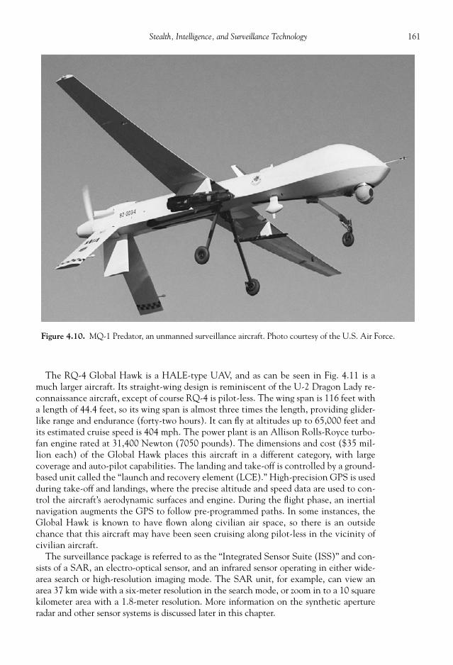
161Stealth, Intelligence, and Surveillance Technology
The RQ-4 Global Hawk is a HALE-type UAV, and as can be seen in Fig. 4.11 is amuch larger aircraft. Its straight-wing design is reminiscent of the U-2 Dragon Lady re-connaissance aircraft, except of course RQ-4 is pilot-less. The wing span is 116 feet witha length of 44.4 feet, so its wing span is almost three times the length, providing glider-like range and endurance (forty-two hours). It can fl y at altitudes up to 65,000 feet andits estimated cruise speed is 404 mph. The power plant is an Allison Rolls-Royce turbo-fan engine rated at 31,400 Newton (7050 pounds). The dimensions and cost ($35 mil-lion each) of the Global Hawk places this aircraft in a different category, with largecoverage and auto-pilot capabilities. The landing and take-off is controlled by a ground-based unit called the “launch and recovery element (LCE).” High-precision GPS is usedduring take-off and landings, where the precise altitude and speed data are used to con-trol the aircraft’s aerodynamic surfaces and engine. During the fl ight phase, an inertialnavigation augments the GPS to follow pre-programmed paths. In some instances, theGlobal Hawk is known to have fl own along civilian air space, so there is an outsidechance that this aircraft may have been seen cruising along pilot-less in the vicinity ofcivilian aircraft.
The surveillance package is referred to as the “Integrated Sensor Suite (ISS)” and con-sists of a SAR, an electro-optical sensor, and an infrared sensor operating in either wide-area search or high-resolution imaging mode. The SAR unit, for example, can view anarea 37 km wide with a six-meter resolution in the search mode, or zoom in to a 10 squarekilometer area with a 1.8-meter resolution. More information on the synthetic apertureradar and other sensor systems is discussed later in this chapter.
Figure 4.10. MQ-1 Predator, an unmanned surveillance aircraft. Photo courtesy of the U.S. Air Force.
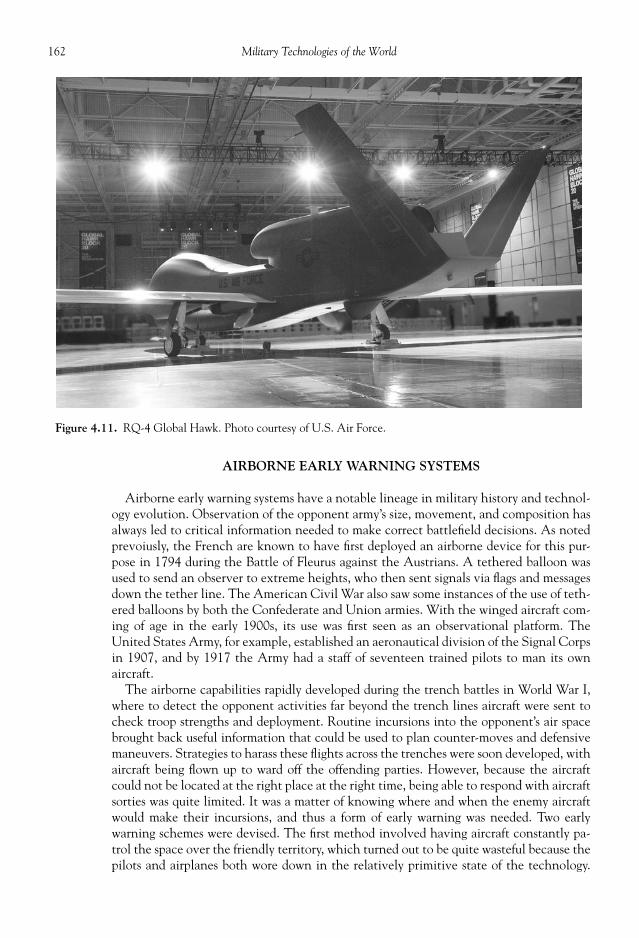
162 Military Technologies of the World
AIRBORNE EARLY WARNING SYSTEMS
Airborne early warning systems have a notable lineage in military history and technol-ogy evolution. Observation of the opponent army’s size, movement, and composition hasalways led to critical information needed to make correct battlefi eld decisions. As notedprevoiusly, the French are known to have fi rst deployed an airborne device for this pur-pose in 1794 during the Battle of Fleurus against the Austrians. A tethered balloon wasused to send an observer to extreme heights, who then sent signals via fl ags and messagesdown the tether line. The American Civil War also saw some instances of the use of teth-ered balloons by both the Confederate and Union armies. With the winged aircraft com-ing of age in the early 1900s, its use was fi rst seen as an observational platform. TheUnited States Army, for example, established an aeronautical division of the Signal Corpsin 1907, and by 1917 the Army had a staff of seventeen trained pilots to man its ownaircraft.
The airborne capabilities rapidly developed during the trench battles in World War I,where to detect the opponent activities far beyond the trench lines aircraft were sent tocheck troop strengths and deployment. Routine incursions into the opponent’s air spacebrought back useful information that could be used to plan counter-moves and defensivemaneuvers. Strategies to harass these fl ights across the trenches were soon developed, withaircraft being fl own up to ward off the offending parties. However, because the aircraftcould not be located at the right place at the right time, being able to respond with aircraftsorties was quite limited. It was a matter of knowing where and when the enemy aircraftwould make their incursions, and thus a form of early warning was needed. Two earlywarning schemes were devised. The fi rst method involved having aircraft constantly pa-trol the space over the friendly territory, which turned out to be quite wasteful because thepilots and airplanes both wore down in the relatively primitive state of the technology.
Figure 4.11. RQ-4 Global Hawk. Photo courtesy of U.S. Air Force.
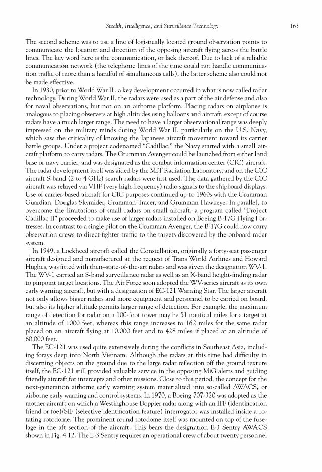
163Stealth, Intelligence, and Surveillance Technology
The second scheme was to use a line of logistically located ground observation points tocommunicate the location and direction of the opposing aircraft fl ying across the battlelines. The key word here is the communication, or lack thereof. Due to lack of a reliablecommunication network (the telephone lines of the time could not handle communica-tion traffi c of more than a handful of simultaneous calls), the latter scheme also could notbe made effective.
In 1930, prior to World War II , a key development occurred in what is now called radartechnology. During World War II, the radars were used as a part of the air defense and alsofor naval observations, but not on an airborne platform. Placing radars on airplanes isanalogous to placing observers at high altitudes using balloons and aircraft, except of courseradars have a much larger range. The need to have a larger observational range was deeplyimpressed on the military minds during World War II, particularly on the U.S. Navy,which saw the criticality of knowing the Japanese aircraft movement toward its carrierbattle groups. Under a project codenamed “Cadillac,” the Navy started with a small air-craft platform to carry radars. The Grumman Avenger could be launched from either landbase or navy carrier, and was designated as the combat information center (CIC) aircraft.The radar development itself was aided by the MIT Radiation Laboratory, and on the CICaircraft S-band (2 to 4 GHz) search radars were fi rst used. The data gathered by the CICaircraft was relayed via VHF (very high frequency) radio signals to the shipboard displays.Use of carrier-based aircraft for CIC purposes continued up to 1960s with the GrummanGuardian, Douglas Skyraider, Grumman Tracer, and Grumman Hawkeye. In parallel, toovercome the limitations of small radars on small aircraft, a program called “ProjectCadillac II” proceeded to make use of larger radars installed on Boeing B-17G Flying For-tresses. In contrast to a single pilot on the Grumman Avenger, the B-17G could now carryobservation crews to direct fi ghter traffi c to the targets discovered by the onboard radarsystem.
In 1949, a Lockheed aircraft called the Constellation, originally a forty-seat passengeraircraft designed and manufactured at the request of Trans World Airlines and HowardHughes, was fi tted with then–state-of-the-art radars and was given the designation WV-1.The WV-1 carried an S-band surveillance radar as well as an X-band height-fi nding radarto pinpoint target locations. The Air Force soon adopted the WV-series aircraft as its ownearly warning aircraft, but with a designation of EC-121 Warning Star. The larger aircraftnot only allows bigger radars and more equipment and personnel to be carried on board,but also its higher altitude permits larger range of detection. For example, the maximumrange of detection for radar on a 100-foot tower may be 51 nautical miles for a target atan altitude of 1000 feet, whereas this range increases to 162 miles for the same radarplaced on an aircraft fl ying at 10,000 feet and to 428 miles if placed at an altitude of60,000 feet.
The EC-121 was used quite extensively during the confl icts in Southeast Asia, includ-ing forays deep into North Vietnam. Although the radars at this time had diffi culty indiscerning objects on the ground due to the large radar refl ection off the ground textureitself, the EC-121 still provided valuable service in the opposing MiG alerts and guidingfriendly aircraft for intercepts and other missions. Close to this period, the concept for thenext-generation airborne early warning system materialized into so-called AWACS, or a irborne early w arning a nd c ontrol s ystems. In 1970, a Boeing 707-320 was adopted as themother aircraft on which a Westinghouse Doppler radar along with an IFF (identifi cationfriend or foe)/SIF (selective identifi cation feature) interrogator was installed inside a ro-tating rotodome. The prominent round rotodome itself was mounted on top of the fuse-lage in the aft section of the aircraft. This bears the designation E-3 Sentry AWACSshown in Fig. 4.12. The E-3 Sentry requires an operational crew of about twenty personnel
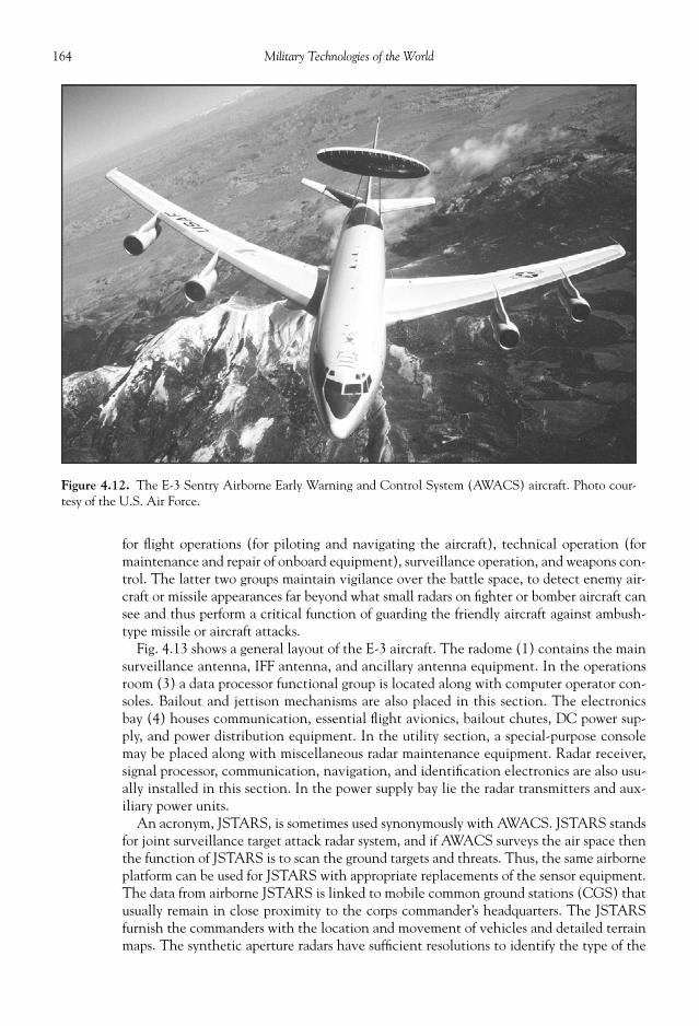
164 Military Technologies of the World
for fl ight operations (for piloting and navigating the aircraft), technical operation (formaintenance and repair of onboard equipment), surveillance operation, and weapons con-trol. The latter two groups maintain vigilance over the battle space, to detect enemy air-craft or missile appearances far beyond what small radars on fi ghter or bomber aircraft cansee and thus perform a critical function of guarding the friendly aircraft against ambush-type missile or aircraft attacks.
Fig. 4.13 shows a general layout of the E-3 aircraft. The radome (1) contains the mainsurveillance antenna, IFF antenna, and ancillary antenna equipment. In the operationsroom (3) a data processor functional group is located along with computer operator con-soles. Bailout and jettison mechanisms are also placed in this section. The electronicsbay (4) houses communication, essential fl ight avionics, bailout chutes, DC power sup-ply, and power distribution equipment. In the utility section, a special-purpose consolemay be placed along with miscellaneous radar maintenance equipment. Radar receiver,signal processor, communication, navigation, and identifi cation electronics are also usu-ally installed in this section. In the power supply bay lie the radar transmitters and aux-iliary power units.
An acronym, JSTARS, is sometimes used synonymously with AWACS. JSTARS standsfor joint surveillance target attack radar system, and if AWACS surveys the air space thenthe function of JSTARS is to scan the ground targets and threats. Thus, the same airborneplatform can be used for JSTARS with appropriate replacements of the sensor equipment.The data from airborne JSTARS is linked to mobile common ground stations (CGS) thatusually remain in close proximity to the corps commander’s headquarters. The JSTARSfurnish the commanders with the location and movement of vehicles and detailed terrainmaps. The synthetic aperture radars have suffi cient resolutions to identify the type of the
Figure 4.12. The E-3 Sentry Airborne Early Warning and Control System (AWACS) aircraft. Photo cour-tesy of the U.S. Air Force.

165Stealth, Intelligence, and Surveillance Technology
Figure 4.13. A general layout of the E-3 Sentry aircraft. The original photo courtesy of the U.S. Air Force.
Figure 4.14. EA-6B Prowler used in the Electronic Attack Squadrons of the U.S. Navy. Photo courtesy of theU.S. Navy.

166 Military Technologies of the World
vehicle and therefore friendly or foe identifi cation capabilities. With JSTARS, essentiallyall the movements and locations of friendly and enemy vehicles are mapped in real timewithin an area of several hundred kilometers.
The above principles of operation for AWACS or JSTARS are carried out by a set ofsophisticated, integrated electronics:
1. Antenna and Rotodome Equipment (this is the radar sensor unit).• One 8 m (26 feet) × 1.3 m (4.5 feet) antenna consisting of twenty-eight slotted
waveguide radiators that provide narrow, focused beams.• Twenty-eight reciprocal beam steering phase shifters.
2. Phase Control Electronics.• Beam angle control circuits.• One high-power channel for transmission, seven coaxial RF channels.• Microwave receiver.
3. Transmit Group.• Transmit low-power amplifi er.• Transmit angle control.• Two high-power Klystron amplifi ers with two pulsers and grid pulser circuits.• Pressurized high-voltage supply units, with 90 kV transformer, fi lter and regulator.• Protection sensors for power distribution and control.
4. Radar Control and Maintenance Panel.• Spectrum analyzers.• Multiple data display units.• Fast Fourier transform displays.
5. Surveillance and Radar Computer.• 24-bit precision with 5 MHz data rate capable of performing 23 billion operations
per second.• 534 real pipelined arithmetic unit gate arrays operating at 20 MHz.
The future AWACS and JSTARS will be required to provide resolutions for yet smallertargets, greater range, and better height accuracy along with improved tracking. In addi-tion, capabilities will be added for identifi cation and tracking of slow-moving targets, he-licopters, and high-speed missiles with diverse frequency scanning.
A Boeing 707-300 aircraft is the platform that carries either AWACS or JSTARSelectronics, with major modifi cations to accommodate the surveillance, communica-tion, and defensive countermeasure equipment. The Boeing 707-300 (with military des-ignations of E-8, EC-135, or E-3 Sentry depending on the use) is powered by four Pratt& Whitney TF33-102C turbofan engines with 19,200 lbs (82,000 N) of thrust each.The maximum take-off weight is 336,000 lbs, and the aircraft is operated by a fl ight crewof four and twenty or so Air Force and Army personnel. The Boeing 707-300 is capableof remaining in fl ight for up to nine hours, but with refueling its endurance can be ex-tended almost indefi nitely. With advances in electronics equipment and to replace theaging Boeing 707-300, a new fl eet of AWACS and JSTARS on the Boeing 767-400Eairframe is planned for the future. The United States along with NATO states operatelong-range early warning aircraft such as AWACS and JSTARS. The air forces of Russia,France, India, Saudi Arabia, Greece, and Japan also possess AWACS aircraft, either oftheir own design or an export version from the United States. The Australian and SouthKorean militaries are also anticipated to acquire the U.S. export version of AWACSbased on the Boeing 737-700 airframe.

167Stealth, Intelligence, and Surveillance Technology
RADARS AND OTHER SENSORS
A number of elements are now considered in electronic intelligence and warfare. Theseare radars, IFF, radio, electronic support measures, infrared sensors, and electronic counter-measures for self-protection. Radars ( ra dio d etection a nd r anging) are powerful devicesdue to their all-weather, day and night capabilities. In addition to long-range target detec-tion, radars provide functions for fl ight operations and weather and terrain monitoring.Thus, radars are capable of surveillance, target tracking, height measurements (of targets
Figure 4.15. Phased-array radar (APG-75) on the nose radome of F/A-18 aircraft. Photo courtesyof the U.S. Department of Defense.

168 Military Technologies of the World
and terrains), and target identifi cation/classifi cation. The electromagnetic frequency thatcan be used for radars ranges from UHF (ultra high frequency, about 400 MHz) to the so-called K a (35 GHz) bands, and selection of the frequency for a particular radar use dependson the target type, land/sea/weather environment, and other mission objectives. For max-imum resolution of target geometry and dimensions, the high-frequency Ka band is useful,with any higher frequency being avoided due to atmospheric attenuation (i.e., limitedrange). Usually, frequencies between 400 MHz (UHF) and 4 GHz (S band) are used formlong-range surveillance. The lower UHF frequencies have the advantage of both low costand improved detection of low radar cross-section targets such as missiles and stealth air-craft, while high frequency radars provide better angular and height resolutions. Table 4.3lists the different radar bands and their primary uses.
In a similar manner to sun light that is refl ected or scattered from solid surfaces andparticles, all electromagnetic waves including those in the radar frequency are refl ectedfrom surfaces. The amount and the manner in which the radar waves are refl ected dependon the surface material, surface fi nish, and shape. Since most aircraft, ships, and othermilitary vehicles are made of metals or carbon fi bers, radar refl ection is usually signifi cantunless a great deal of effort is made to make the surface resistant to radar detection usingstealth technology. The frequency of the radar wave also dictates the characteristics of the
Figure 4.16. A close-up view of the radar used in fi ghter-bomber aircrafts. Photo courtesy of the U.S. AirForce.

169Stealth, Intelligence, and Surveillance Technology
return signals as well as their propagation in theatmosphere. As noted previously, high frequencyand therefore short-wavelength waves are usefulfor discerning the shape of the target in high-resolution radars, but these waves are easily ab-sorbed by the atmosphere and therefore theirenergy quickly diminishes over a distance. Mili-tary radars use a range of radar frequencies invarious confi gurations to achieve the missionobjectives.
The use of the radar spans across all branchesof the military and serves many important func-tions. Installed in a fi ghter/interceptor aircraft,the radar gives the capabilities for search, threatassessments, and weapons management includ-ing fi re control. The fi re control aspect is achievedby the radar generating the data needed forcalculation of the optimum engagement angle,range, and speed for the armament. The searchmode needs to cover a large volume of informa-tion involving range and angular coverage andthus may give the operator a situational aware-ness but not the details of the target signals. Thetrack mode, on the other hand, uses a narrow“pencil” of radar waves at optimum frequencies to
Table 4.3. Radar Bands (adopted from http://en.wikipedia.org/wiki/Radar)
Band Frequency Wavelength Primary Use
HF 3–30 MHz 10–100 m Over-the-horizon radarsP <300 MHz >1 m Early radar systemsVHF 50–330 MHz 0.9–6 m Very long-range radars, ground
penetrating radarsUHF 300–1000 GHz 0.3–1 m Ballistic missile early warning radarsL 1–2 GHz 15–30 cm Long-range air traffi c control and
surveillanceS 2–4 GHz 7.5–15 cm Terminal air traffi c controlC 4–8 GHz 3.75–7.5 cm Satellite trackingX 8–12 GHz 2.5–3.75 cm Missile guidance, marine radars,
weather radarsKu 12–18 GHz 1.67–2.5 cm Satellite altimetry, high-resolution
mappingK 18–27 GHz 1.11–1.67 cm Meteorological radars, speed gunsKa 27–40 GHz 0.75–1.11. cm Airport surveillance, short-range
mapping, traffi c control radarsmm 40–300 GHz 7.5–1 mmQ 40–60 GHz 5–7.5 mm Military communicationsV 50–75 GHz 4–6 mmE 60–90 GHz 3.33–6 mmW 75–110 GHz 2.7–4 mm High-resolution meteorological radars
Figure 4.17. An artistic rendition of the modern mis-sile early warning reconnaissance satellite. Imagecourtesy of the U.S. Air Force.

170 Military Technologies of the World
Figure 4.18. The synthetic aperture radar used in the BMEWS (Ballistic missile early warningsystem) site in Thule Air Base, Greenland. Photo courtesy of the U.S. Air Force.
Figure 4.19. A typical radar display showing the surface scan in a polar coordinate (circumferentialangle). Photo courtesy of the U.S. Navy.
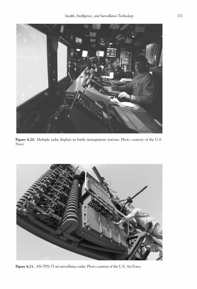
171Stealth, Intelligence, and Surveillance Technology
Figure 4.20. Multiple radar displays in battle management stations. Photo courtesy of the U.S.Navy.
Figure 4.21. AN-TPS-75 air surveillance radar. Photo courtesy of the U.S. Air Force.

172 Military Technologies of the World
identify the number and type of threats discovered in the scan mode. The high resolutionof the radar interrogation in this mode gives the detailed range and speed using the Dop-pler shift. Most modern military radars allow track-while-scan so that both the overallbattlefi eld situation as well as the detailed threat tracking can be accomplished simultane-ously. Although IFF is fi rst deployed discern the detected objects, more precise determina-tion of the target is possible by analyzing the refl ected radar echo. In some advancedsystems with high resolution, a two-dimensional radar image of the target is made to fa-cilitate the identifi cation as opposed to just analyzing the one-dimensional radar echoes.The fi re control for close-range weapons like aircraft cannons requires the radar data sothat the lead pursuit path to the target can be computed and displayed on the HUD(heads-up display). Also, the fi re cross-hair will be displayed on the HUD to prompt thepilot to pull the trigger, again based on radar input on the speed, range, and angle of thetarget. For beyond-visual-range engagements using missiles like the AMRAAM, targetupdate data from the aircraft radar can be transmitted to the missile should the targetmake sudden course changes after the missile launch. For terminal guidance, AMRAAMand other active-radar missiles use their own onboard radars to home in on the target.
Even longer-range searching and tracking can be accomplished by bigger radars in-stalled on airborne platforms such as the AWACS, the EA-61 Prowler, and other elec-tronic warfare aircraft. The ultramodern radar installed on the F-22 Raptor has estimatedcapabilities that in some aspects equal those on dedicated electronic warfare aircraft.Other important utilities of radars include high-resolution terrain mapping using SAR(described later), air traffi c control, altimetry for low-altitude fl ights and terrain avoid-ance, precision velocity updates, and weather avoidance. Low-altitude fl ights are oftenused to avoid detection by the enemy radars; however, to maintain a low altitude withoutrisking running into terrains precise altitude information is obtained from the time for theradar echo from the ground to come back to the sounding radar. To prevent disclosure bythis radar operation, the altimetry radar is operated at very low PRF (pulse repetition fre-quency) and also using the radar frequency control—the radar power is spread over a verywide frequency ranges. For the precision velocity update, three thin radar beams are sentforward and down at shallow angles. The Doppler frequency of the returning signals thengives the speed of the aircraft with respect to the ground. Used extensively in meteorologyand weather forecasting, Doppler radars detect the presence and speed of weather systemsbearing rain drops that also refl ect radar waves effectively. Again, the Doppler shift givesthe speed of the storm fronts bearing rains. Using the same principle, wind shear (a suddenchange in the horizontal wind velocity from one altitude to another) can be detected in arain-bearing storm system by measuring the front velocity as a function of the altitudeusing Doppler radar.
Electromagnetic waves are generated as an electrical charge oscillates in time. The AMradio noise heard when an electrical appliance is turned on (e.g., fan) nearby is an exampleof radio waves being generated by the alternating current of the household electricity. Byaltering the current and frequency of the electrical oscillation, radar waves can be gener-ated in different bands as listed in Table 4.3. Technically, these oscillators or “transmitters”are given names such as “klystron” and “magnetron,” but the underlying principle of op-erations is the oscillation of electrical charges. For example, a magnetron is a circular tubeacting as the anode (positive electrode) with a central cathode (negative electrode) core.A strong DC voltage is applied across the cathode and also to the central core to heat itup through electrical resistance. The latter effect is to generate electrodes from the cath-ode surface, which then would be drawn toward the positive anode and stream toward itunder vacuum conditions inside the magnetron. The acceleration of electrons under per-manent magnets that surround the magnetron induces circular motion of the electrons.
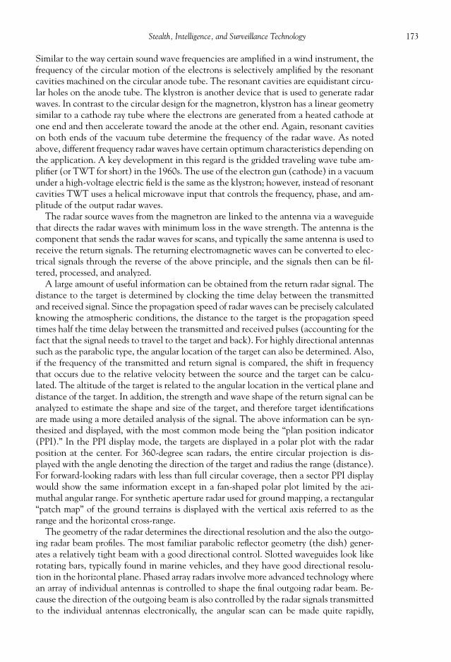
173Stealth, Intelligence, and Surveillance Technology
Similar to the way certain sound wave frequencies are amplifi ed in a wind instrument, thefrequency of the circular motion of the electrons is selectively amplifi ed by the resonantcavities machined on the circular anode tube. The resonant cavities are equidistant circu-lar holes on the anode tube. The klystron is another device that is used to generate radarwaves. In contrast to the circular design for the magnetron, klystron has a linear geometrysimilar to a cathode ray tube where the electrons are generated from a heated cathode atone end and then accelerate toward the anode at the other end. Again, resonant cavitieson both ends of the vacuum tube determine the frequency of the radar wave. As notedabove, different frequency radar waves have certain optimum characteristics depending onthe application. A key development in this regard is the gridded traveling wave tube am-plifi er (or TWT for short) in the 1960s. The use of the electron gun (cathode) in a vacuumunder a high-voltage electric fi eld is the same as the klystron; however, instead of resonantcavities TWT uses a helical microwave input that controls the frequency, phase, and am-plitude of the output radar waves.
The radar source waves from the magnetron are linked to the antenna via a waveguidethat directs the radar waves with minimum loss in the wave strength. The antenna is thecomponent that sends the radar waves for scans, and typically the same antenna is used toreceive the return signals. The returning electromagnetic waves can be converted to elec-trical signals through the reverse of the above principle, and the signals then can be fi l-tered, processed, and analyzed.
A large amount of useful information can be obtained from the return radar signal. Thedistance to the target is determined by clocking the time delay between the transmittedand received signal. Since the propagation speed of radar waves can be precisely calculatedknowing the atmospheric conditions, the distance to the target is the propagation speedtimes half the time delay between the transmitted and received pulses (accounting for thefact that the signal needs to travel to the target and back). For highly directional antennassuch as the parabolic type, the angular location of the target can also be determined. Also,if the frequency of the transmitted and return signal is compared, the shift in frequencythat occurs due to the relative velocity between the source and the target can be calcu-lated. The altitude of the target is related to the angular location in the vertical plane anddistance of the target. In addition, the strength and wave shape of the return signal can beanalyzed to estimate the shape and size of the target, and therefore target identifi cationsare made using a more detailed analysis of the signal. The above information can be syn-thesized and displayed, with the most common mode being the “plan position indicator(PPI).” In the PPI display mode, the targets are displayed in a polar plot with the radarposition at the center. For 360-degree scan radars, the entire circular projection is dis-played with the angle denoting the direction of the target and radius the range (distance).For forward-looking radars with less than full circular coverage, then a sector PPI displaywould show the same information except in a fan-shaped polar plot limited by the azi-muthal angular range. For synthetic aperture radar used for ground mapping, a rectangular“patch map” of the ground terrains is displayed with the vertical axis referred to as therange and the horizontal cross-range.
The geometry of the radar determines the directional resolution and the also the outgo-ing radar beam profi les. The most familiar parabolic refl ector geometry (the dish) gener-ates a relatively tight beam with a good directional control. Slotted waveguides look likerotating bars, typically found in marine vehicles, and they have good directional resolu-tion in the horizontal plane. Phased array radars involve more advanced technology wherean array of individual antennas is controlled to shape the fi nal outgoing radar beam. Be-cause the direction of the outgoing beam is also controlled by the radar signals transmittedto the individual antennas electronically, the angular scan can be made quite rapidly,
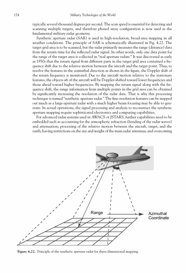
174 Military Technologies of the World
typically several thousand degrees per second. The scan speed is essential for detecting andscanning multiple targets, and therefore phased array confi guration is now used as thefundamental military radar geometry.
Synthetic aperture radar (SAR) is used in high-resolution, broad-area mapping in allweather conditions. The principle of SAR is schematically illustrated in Fig. 4.22. Thetarget grid area is to be scanned, but the radar primarily measures the range (distance) datafrom the return time for the refl ected radar signal. In other words, only one data point forthe range of the target area is collected in “real aperture radars.” It was discovered as earlyas 1950s that the return signal from different parts in the target grid area contained a fre-quency shift due to the relative motion between the aircraft and the target point. Thus, toresolve the features in the azimuthal direction as shown in the fi gure, the Doppler shift ofthe return frequency is monitored. Due to the aircraft motion relative to the stationaryfeatures, the objects aft of the aircraft will be Doppler-shifted toward lower frequencies andthose ahead toward higher frequencies. By mapping the return signal along with the fre-quency shift, the range information from multiple points in the grid area can be obtainedby signifi cantly increasing the resolution of the radar data. That is why this processingtechnique is named “synthetic aperture radar.” The fi ne-resolution features can be mappedout much as a large-aperture radar with a much higher beam focusing may be able to gen-erate. In actual operations, the signal processing and analysis to reconstruct the syntheticaperture mapping require sophisticated electronics and computing capabilities.
For advanced radar systems used in AWACS or JSTARS, further capabilities need to beembedded such as accounting for the atmospheric refraction (bending of the radar waves)and attenuation; processing of the relative motion between the aircraft, target, and theearth; having restrictions on the size and weight of the main radar antennas; and overcoming
Figure 4.22. Principle of the synthetic aperture radar for three-dimensional mapping.

175Stealth, Intelligence, and Surveillance Technology
jamming and other electromagnetic interferences. With effective stealth technologiesnow being available, the radar technology must be improved to overcome the diffi cultiesassociated with detecting stealth aircraft as well as fast, low-altitude, low radar cross-section threats such as cruise missiles.
In addition to the radars, early warning systems now include other sensors and devicesaugmenting the radar scan and track capabilities. The IFF is a critical element in providinga radar-generated map of the battlefi eld situation. The IFF works by the land-based station,ship, or an aircraft (conventional or AWACS) sending an interrogating signal, typically at1030 MHz, and the friendly aircraft responding with a coded reply at a shifted frequency,typically at 1090 MHz. The process is automated with the code input to the transpondersand altered on a regular basis to avoid countermeasures. Any aircraft not responding withthe correct coded reply is identifi ed as opposing aircraft and duly displayed on the com-puter monitor. However, one fault in this system lies in the fact that it only identifi esfriendly aircraft with an IFF transponder operating at that time. Civilian or neutral air-craft, or even friendly aircraft with outdated codes, are all classifi ed as foes under this sys-tem. A tragic incident in 1988 is an example of the possibility of a misidentifi cation. AnIranian commercial airliner, an A300 Airbus, was shot down by a missile launched fromthe U.S. Navy Aegis-class cruiser Vincennes. The confusion apparently arose due to thetwo confl icting codes being detected, a military mode 2 and a civil mode A, and the factthat the Airbus was observed to descend toward the cruiser in an apparent attack pattern.Despite the circumstances, this incident throws some shadows on the lack of positiveidentifi cation using this type of IFF method.
Electronic support measures (ESM) refer to scanning of a very large range of electro-magnetic spectrum and using the data to identify and locate the source of the detectedsignals. Most military vehicles during normal operations (under non-radio-silence opera-tions) emit a variety of electromagnetic emissions associated with radio communications,navigation, and also their own radars. By cataloging the electromagnetic characteristicsused by major military forces and analyzing their signal strength and direction, much in-formation can be added to that obtained from the conventional transmit/receive radars.ESM is by defi nition a passive intelligence method, with the receiver scanning across awide range of electromagnetic frequencies.
The methods described above are used in various combinations and modes dependingon the mission requirements. In the pulse Doppler non-elevation scans, all objects in theair down to the surface level area scanned for angular location and speed. The beyond-the-horizon mode is used for extended-range surveillance without the Doppler signal process-ing, with the beam pointing above the horizon to minimize the ground clutter. The pulseDoppler elevation scan refers to the radar operation in which the radar beam is scanned inthe vertical direction to resolve the angular location, altitude, and speed of the targets.Finally, the passive mode is used as electronic support measure (ESM) by turning off theradar transmitters and monitoring for the incoming signals only.
For the ballistic missile early warning system (BMEWS), a combination of radar capa-bilities logistically located in and outside of the United States territory is used. The threesites (BMEWS) are located in (1) the U.S. Air Force facility in Thule, Greenland, (2)Clear Air Force Station in Alaska, and (3) a Royal Air Force facility at Fylingdales, UnitedKingdom, as discussed in Chapter 5 of this book. The site at Fylingdales operates an AN/FPS-49 surveillance and tracking radar, while Clear Air Force Station uses a group of ra-dars—an AN/FPS-92, a FPS-49, and three AN/FPS-50 surveillance radars. At Thule, fourFPS-50s and a phased array radar, the AN/FPS-115, monitors the space. The FPS-49tracking radar’s 82-ft dish is housed in a 141-ft diameter radome. It has a maximum scanrange of 3110 miles in the UHF operating frequency range (see Table 4.3). The FPS-50

176 Military Technologies of the World
radar is even larger with a parabolic-torus refl ector at a 400-ft width and a 165-ft height.Its scan range is approximately 3000 miles, and it has an angular coverage of 160 degreeswith an elevation scan capability of 3.5 to 7 degrees. The FPS-115 phased array radar sendsand receives signals from two faces with an approximately 90-ft diameter and a range thatexceeds 3000 miles. As noted above, phased array radar has fi xed orientation, but it cancover wide angles through electronic control of the phased array elements. For the FPS-115, the angular coverage is 120 degrees with elevation scans from 3 to 85 degrees.
Precision Acquisition Vehicle Entry Phased Array Warning System or PAVE PAWS isan integral component of the U.S. ballistic missile early warning network, with a primaryfunction of detecting and tracking submarine-launched ballistic missiles. The U.S. PAVEPAWS carries the designation AN/FP-115, and the sites are located to monitor both theAtlantic and the Pacifi c Oceans: Cape Cod Air Force Station in Massachusetts, Beale AirForce Base in California, Robins Air Force Base in Georgia, and Eldorado Air Force Basein Texas. The PAVE PAWS in these installations have three faces with a 20-degree tiltfrom the vertical, and the enclosure building covers close to 77,000 square feet. The angu-lar coverage of 240 degrees with an elevation scan from 3 to 85 degrees can be made usingFP-115 radars with tracking capability up to 3455 miles.
ELECTRONIC COUNTER- AND COUNTER-COUNTERMEASURES
Electronic countermeasures (ECM) refer to methods to defeat the probing radar beams,while electronic counter-countermeasures (ECCM) attempt to defeat them (ECM). Thereis a large variety of ECM methods, but they can be classifi ed under one of the following:chaff, jamming, false targets/decoys, gate stealers, and angle deception. Chaffs were usedalmost immediately after radars went into use during World War II. The radar technologywas known on both sides of the Atlantic, and thus it was relatively straightforward toconjure up a scheme to interfere with the radar operation in detecting metal objects suchas aircrafts. By dispersing strips of metal foils, the radar waves would be refl ected off thesechaffs, thus either giving false signals or shielding the actual aircraft. In modern chaff,literally billions of thin metal-coated fi bers are stored in a casing the size of a penny, andwhen dispersed they tend to stay aloft in the air for persistent refl ection of the radar sig-nals. Although radar techniques such as the moving target indicator can discern actualtargets from such stationary chaff elements, again they can be used for shielding purposesor at least provide an alternate refl ector. The latter can be effective on less capable radars,such as those on air-to-air missiles, by introducing tracking noise that can cause a break inthe radar lock during evasive maneuvers. An interesting effect is that the return signalfrom the chaff elements is the strongest in the probe radar frequency; however, due toresonance effect multiples of the source frequency are also scattered, which depends onthe length-to-diameter ratio of the chaff fi bers. To saturate the return frequency range, aset of chaff fi bers with selected length-to-diameter ratios is used.
Jamming or noise jamming is a simple but effective method where a strong, broadbandradar signal is broadcast to saturate the opposing radars. In modern applications, the noisejamming is tuned to the opposing radar frequency by occasionally monitoring the incomingradar frequencies and then using a frequency-tuning circuit to generate jamming noise. Inspite of the fact that the jamming radar acts as a loud beacon to signal the presence of hos-tile intent, it does eliminate the ranging capabilities of the opposing radars. Thus, the range,number, and direction of the approaching force cannot be determined by the other side.They may be aware of something afoot, but cannot confi rm, identify, or engage the ap-proaching force using any of the radar-based weapons. For this reason, noise jamming is very
177Stealth, Intelligence, and Surveillance Technology
effective in shielding large, multiple attacking groups, particularly if emitted by an indepen-dent electronic warfare aircraft or vehicle. Also, multiple aircraft can sequentially employnoise jamming so that even passive radar scans by the opposing side become useless. Todefeat multiple radars operating in different frequencies, a number of jamming tactics areused. The entire radar frequency spectrum can be continuously swept by jamming radarnoise to saturate the opposing radars, but this of course dilutes the amplitude and time. Analternate method is the “spot jamming” where the only observed radar frequencies are se-lectively jammed in sequence or simultaneously. However, even spot jamming takes a lot ofradar power, which may result in leakage or consume too much of the radar power available.An advanced method called “bin masking” circumvents this diffi culty. In the range binmasking method, the incoming probe radar signal is monitored, and jamming noise is gen-erated only in the time interval that the probe radar is expected to receive the return signalfrom the jamming aircraft. This is particularly useful against low- to medium-PRF (pulserepetition frequency) radars. For high-PRF radars, velocity bin masking is used. As notedabove, the velocity of targets is observed through the Doppler frequency shift of the radarreturn signal. Velocity bin masking again responds to the incoming probe radar signal,determines its frequency, and immediately shifts the frequency to emit that particular fre-quency through the jamming radar. The result is that the radar frequency range correspondingto the Doppler shifts of the target velocity becomes saturated.
False targets methods generate simulated return signals so that the hostile radar fails tocorrectly locate the aircraft. In the false target method, a compact electronic device fi rstwaits for the probe beam to arrive and then transmits a simulated signal after a desiredtime delay to simulate the false range and speed. This kind of false-echo device is called atransponder. In repeater–type devices, much more realistic echo signals can be generatedby storing the incident radar waveform, generating the same waveform the computermemory, and then electronically amplifying and transmitting the reproduced radar wave-form after a desired time delay. To add to the confusion, false time delays as well as Dopplershifts can be added to the transmitted beams in both the transponder and repeaters so thatthe observer may be induced into believing they are looking at a larger number of incom-ing objects spread out over a wide range and speed. If any of the false target circuitry isinstalled in either towed or expendable decoys, then the device is called an active radardecoy. In passive decoys, a spherical radar refl ector is used to simulate the radar cross sec-tion of the deploying aircraft. The decoys are designed to match the speed of the deployingaircraft, at least during the initial phase of dispersal, so that the radar signature appearsidentical until the aircraft breaks off in an evasive maneuver leaving the decoy to attractthe incident radar-guided projectiles.
As noted previously, probably the fi rst electronic countermeasure, chaff, was inventedbased on the knowledge of the operating principles of radar. As the operating principles ofthe electronic countermeasures are also well known (to much greater detail than divulgedin this book), people will always come up with ideas to defeat these ECM methods in apotentially never-ending cycle of one-upmanship at a grand scale. Standard electroniccounter-countermeasures (ECCM) methods against sources of ECM are frequency agilityand angle and range tracking on the jamming so that the jamming source can be engagedand destroyed. Constant changes in the radar frequency in the frequency agility approachprevent the ECM jammers from locking on to a particular frequency, in which case theonly recourse may be an ineffi cient “barrage jamming” across broad frequency ranges.However, some pulse Doppler radars rely on persistent use of fi xed-frequency radar signals,so they are prone to ECM measures, and other methods are needed to defeat the ECMsource. In modern pulse Doppler radars using fi xed frequencies, the angle-on jamming(AOJ) mode can be invoked, which displays the jamming radar signal as a bright line

178 Military Technologies of the World
without the range data but showing the direction from which the jamming signal is com-ing. The AOJ mode is alternatively known as jam angle attack (JAM) or angle track-onjamming (ATOJ). This angular data allow the defender to point the anti-jamming weap-ons in the correct direction. There are missiles with home-on jamming (HOJ) guidancethat seeks the “hottest” radar signature, and if these missiles are sent in the right directionthey have a high probability of making a hit.
Although ECM jamming precludes active determination of the target range, there arepassive ranging algorithms again so that the target location can be determined. For ex-ample, in the angle-rate ranging algorithm the ECCM aircraft (own aircraft) changes itsheading, which then would alter the direction from which the ECM jamming radar signalis received. As noted above, using the AOJ mode the direction of the ECM signal can bedetermined. The rate of change of this angle, angle-rate, depends on the velocity differ-ence between the own aircraft and the hostile aircraft, as well as the distance between thetwo aircraft. With the velocity of the own aircraft is known, the distance is calculated bycontinuously monitoring the angle-rate assuming that the hostile aircraft’s velocity is con-stant. This method is limited by the latter assumption in that if the hostile aircraft changesits heading or speed then the distance calculation would be unfounded. Also, since thealgorithm relies on angular data it is mostly effective at short ranges where the relativevelocity will produce appreciable change in the angles. A related method is the classic“triangulation,” where the aircraft again locates the angle of the incoming ECM signal atone position and takes another angular data point after traversing to another position asdetermined by inertial navigation or GPS. Triangulation also assumes that the hostileaircraft has not made course changes during the time it takes for the own aircraft to makethe traverse. To circumvent this limitation, triangulation can be performed by two aircraftor in conjunction with a ground-based radar with similar angular resolution capabilitiesspaced at optimum distance to pinpoint the hostile aircraft. The radar signal strength de-creases as the distance increases, or mathematically the radar signal strength is inverselyproportional to the square of the distance. Thus, by monitoring the radar strength therange information can be deduced, except that other factors such as the change in theradar angle can drastically alter the radar signal strength.
STEALTH TECHNOLOGY
Stealth technology is a general term referring to methods to reduce the visibility andtherefore the probability of detection by radar, infrared, or other probe beams. Althoughmost prominently used in stealth aircraft, its application extends to all military vehiclesand personnel. For stealth aircraft such as the F-117A and B-2 (shown in Fig. 4.23), anumber of different technologies have gone into providing extremely low radar visibility.First, the geometry of the aircraft has a signifi cant effect on the radar cross section, alongwith the aircraft size. The radar cross section refers to the strength of the refl ected radarsignal relative to the incident radar beam intensity. As the term “cross section” implies, asurface perpendicular to the surface or close to that orientation will tend to have the larg-est cross-sectional area as seen by the beam and will refl ect the most of the incident radarenergy. By slanting the surface, much of the radar energy can be directed to other angles.Most long-range radars will scan in the nearly horizontal directions, and therefore verticalprotrusions will show up very brightly in radar scans. In addition, intersecting metallicplates and rotating elements such as propellers, fans, and turbine blades are associated withlarge radar cross sections. Intersecting plates form corners to effectively bounce the radarenergy back in the direction that it came from, essentially acting like radar mirrors. In theF-117A, the combination of vertical and horizontal tails has been combined into a single

179Stealth, Intelligence, and Surveillance Technology
set of tail surfaces at a low slant angle. In B-2 bombers, there are no rear stabilizers nor anyaerodynamic surfaces above the main wing plane. In gas-turbine engines, there are usuallyrotating elements such as the fan and turbine blades that may be exposed to radar probebeams through openings in the engine intake or the exhaust nozzle. In Fig. 4.15, it can beseen that the air intake and the exhaust nozzles are shrouded in both the F-117A and the
Figure 4.23. F-117A stealth aircraft (above) and B-2 Spirit stealth bomber (below). Photo courtesy of theU.S. Air Force.

180 Military Technologies of the World
B-2 Spirit. The weapons and other external devices that may by carried underneath thewing in non-stealth aircraft are all stored in internal bays to minimize protrusions andtherefore radar cross sections. In some of the modern aircraft such as the F-22 Raptor, thethrust vectoring not only gives higher maneuverability, but it also circumvents the use ofsome aerodynamic surfaces that may form intersecting surfaces and therefore result in alarge radar cross section.
In addition to the aircraft geometry, the material itself may be chosen or fabricated forminimum radar refl ection. Metallic and carbon fi ber surfaces refl ect many of the incidentradar beams. Composites with ferrite additives can be synthesized for low radar refl ectivity andthus are good material for the aircraft wing-body for low radar cross section. Radar-absorbingpaint contains micron- or nano-sized iron-based particles that oscillate under the incomingradar beam and dissipate the radar energy into heat. Urethane foam shaped into tiny pyramidscan be layered beneath the aircraft skin, to again absorb the incident radar energy.
NIGHT VISION SYSTEMS
The ability to sense the surrounding and the enemy movements under adverse conditionsenhances all phases of military operations, from aircraft-based long-range surveillance mis-sions to army personnel seeking the enemy during a night ambush. The night vision systemhas been in existence since the 1950s, and now it has become standard equipment for U.S.soldiers during nighttime operations. Figure 4.24 shows a typical image as observed through
Figure 4.24. A view through a night vision scope. Photo courtesy of the U.S. Army.

181Stealth, Intelligence, and Surveillance Technology
a night vision scope or goggle. The low light level is amplifi ed electronically, and one can seethat any signifi cant light such as the fl ashlight held by the soldier saturates the night visionscope and appears as bright white. The night vision display is usually projected in green be-cause the human eye is most sensitive to green and is able to discern the fi ne shade differ-ences. In theory, the display could be made in full color, but this may have little bearing onthe actual color of the objects and therefore become confusing.
There are two principle methods through which night vision is enabled. One is elec-tronic amplifi cation of the light. Even under what may be perceived as total darkness,there is usually a weak but fi nite source of light such as stars, moon, distant lights, andother man-made sources. It is a matter of amplifying these light signals to a level wherehuman eyes can easily discern shapes and objects. The second method is infrared imaging,sometimes also called thermal imaging.
Light amplifi cation uses a device called image intensifi ers sometimes called microchannelplates due to their internal geometry. Image intensifi ers are used in military night vision,astronomical imaging, and other scientifi c applications where low-level light signals need tobe detected and viewed. They work by generating electrons when the light goes through theobject lens and hits a photocathode screen. A photocathode is a device that releases elec-trons in response to light. The electrons released from a given point on the photocathodetravel through micron-sized channels (the microchannel plate) that are negatively biased(i.e., one side of an electrical power supply is connected to these channels). The negativebias means that there is an abundance of electrons, and when the electron released from thephotocathode hits the channel surface multiple electrons spring from the surface. This pro-cess continues to occur along the channel until an avalanche of electrons are produced.Thus, in comparison to the photocathode by itself, a signifi cantly greater number of elec-trons are produced in response to the light. The electron stream constitutes current that canbe collected for each channel location and converted to an amplifi ed, digital image (such asthe one shown in Fig. 4.24) and displayed on an LCD or other devices for viewing. Althougha gain of 1 million times or more can be achieved in some image intensifi ers, for night visionapplications gains of 20,000 times or above are typically used.
High gain using low power, sensitivity over a large wavelength range including infrared,large fi eld-of-view, and good spatial resolution are some of the desired characteristics innight vision devices. A typical fi eld of view may be about 40 degrees whereas the normalhuman peripheral vision covers 190 degrees. Also, due to the microchannel design thenumber of pixels that can be used in image intensifi er devices is much less than that fornormal digital imaging systems. Unlike digital cameras, image intensifi ers have a lifetimeon the order of 10,000 hours due to the microchannels deterioration over extended usage.
The name “thermal imaging” originates from the fact that all objects at different surfacetemperatures emit light in the infrared by a different amount and at different wavelengths.In fact, if the surface temperature is high enough we start to see this emitted light in thevisible wavelength range, fi rst in the red color, thus leading to the English expression “redhot.” If the object is heated to a yet higher temperature, yellow, green, and blue compo-nents of the light will be radiated from the surface. All of the rainbow colors combinedwill tend to appear white, and thus the English phrase “white hot.” In fact, there is a pre-cise relationship between the wavelength (color) and the amount of radiation emittedfrom the surface and its temperature, as shown in Fig. 4.25. It can be seen that below atemperature of 1000 K or 727o C, the amount of radiation (called the “blackbody spectralintensity” in Fig. 4.17) is small and occurs only in the infrared from a wavelength of 1 to25 microns and beyond. One micron is one-millionth of a meter or one-thousandth of amillimeter. It is only when the temperature exceeds 1000 K that we start seeing at least aportion of the emission in the visible range. Indeed, at higher temperatures much of the

182 Military Technologies of the World
Figure 4.25. Plot of the emitted light at different temperatures. The vertical axis is the amountof emitted light, while the horizontal axis is the wavelength at which the light is emitted. Photocourtesy of the U.S. Department of Defense.
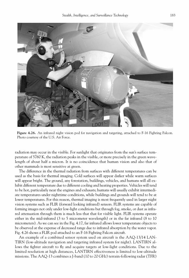
183Stealth, Intelligence, and Surveillance Technology
radiation may occur in the visible. For sunlight that originates from the sun’s surface tem-perature of 5760 K, the radiation peaks in the visible, or more precisely in the green wave-length of about half a micron. It is no coincidence that human vision and also that ofother mammals is most sensitive at green.
The difference in the thermal radiation from surfaces with different temperatures can beused as the basis for thermal imaging. Cold surfaces will appear darker while warm surfaceswill appear bright. The ground, any forestation, buildings, vehicles, and humans will all ex-hibit different temperature due to different cooling and heating properties. Vehicles will tendto be hot, particularly near the engines and exhausts; humans will usually exhibit intermedi-ate temperatures under nighttime conditions, while buildings and grounds will tend to be atlower temperatures. For this reason, thermal imaging is most frequently used in larger nightvision systems such as FLIR (forward looking infrared) sensors. FLIR systems are capable offorming images not only under low-light conditions but through fog, smoke, or dust as infra-red attenuation through them is much less that that for visible light. FLIR systems operateeither in the mid-infrared (3 to 5 micrometer wavelength) or in the far infrared (8 to 10micrometers). As we can see in the Fig. 4.17, far infrared allows lower temperature objects tobe observed at the expense of decreased range due to infrared absorption by the water vapor.Fig. 4.26 shows a FLIR pod attached to an F-16 Fighting Falcon aircraft.
An example of a combined sensor system used on aircraft is the AAQ-13/14 LAN-TIRN ( l ow- a ltitude n avigation and t argeting i nfra r ed system for n ight). LANTIRN al-lows the fi ghter aircraft to fl y and acquire targets at low-light conditions. Due to thelimited resolution at high distances, LANTIRN effectiveness is limited to low-altitudemissions. The AAQ-13 combines a J-band (10 to 20 GHz) terrain-following radar (TFR)
Figure 4.26. An infrared night vision pod for navigation and targeting, attached to F-16 Fighting Falcon.Photo courtesy of the U.S. Air Force.
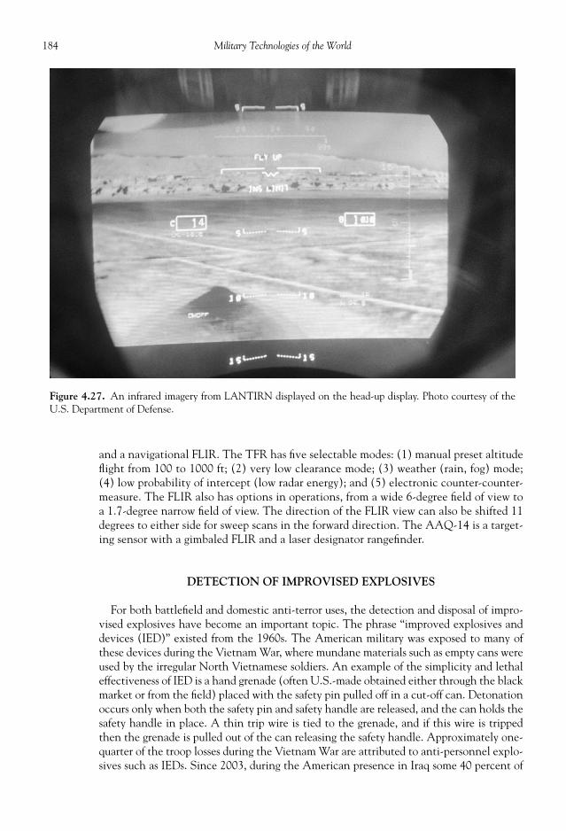
184 Military Technologies of the World
and a navigational FLIR. The TFR has fi ve selectable modes: (1) manual preset altitudefl ight from 100 to 1000 ft; (2) very low clearance mode; (3) weather (rain, fog) mode;(4) low probability of intercept (low radar energy); and (5) electronic counter-counter-measure. The FLIR also has options in operations, from a wide 6-degree fi eld of view toa 1.7-degree narrow fi eld of view. The direction of the FLIR view can also be shifted 11degrees to either side for sweep scans in the forward direction. The AAQ-14 is a target-ing sensor with a gimbaled FLIR and a laser designator rangefi nder.
DETECTION OF IMPROVISED EXPLOSIVES
For both battlefi eld and domestic anti-terror uses, the detection and disposal of impro-vised explosives have become an important topic. The phrase “improved explosives anddevices (IED)” existed from the 1960s. The American military was exposed to many ofthese devices during the Vietnam War, where mundane materials such as empty cans wereused by the irregular North Vietnamese soldiers. An example of the simplicity and lethaleffectiveness of IED is a hand grenade (often U.S.-made obtained either through the blackmarket or from the fi eld) placed with the safety pin pulled off in a cut-off can. Detonationoccurs only when both the safety pin and safety handle are released, and the can holds thesafety handle in place. A thin trip wire is tied to the grenade, and if this wire is trippedthen the grenade is pulled out of the can releasing the safety handle. Approximately one-quarter of the troop losses during the Vietnam War are attributed to anti-personnel explo-sives such as IEDs. Since 2003, during the American presence in Iraq some 40 percent of
Figure 4.27. An infrared imagery from LANTIRN displayed on the head-up display. Photo courtesy of theU.S. Department of Defense.

185Stealth, Intelligence, and Surveillance Technology
the losses were caused by IEDs. By this time, there were many more electronic gadgets thatcould be used in IEDs—digital clocks, walkie-talkies, cell phones, and so forth to triggerthe explosives.
The explosive material itself could be from unexploded bombs or homemade chemicalconcoctions. The military explosives are typically TNT, RDX, PETN, and related chemicalcompounds designed for large heat release, low smoke, and stability under diverse storageconditions. Explosive compounds, however, can be synthesized from chemicals that are notdiffi cult to obtain through commercial or natural sources. It may be recalled that the earlyexplosive black powder was discovered while experimenting with various mixes of materials,including saltpeter, sulfur, and charcoal carbon. Several hundred combinations exist wherea crude mix of common materials, even some household chemicals, can yield substantialexplosive characteristics. Many of these combinations may not exhibit some of the requiredproperties such as long-term stability and handling safety, but then for some unconventionaluses such issues are of minimal concern. Rather detailed information on production of thesedangerous chemicals appears to already have been placed in public domains, but withoutadding any unneeded details improvised explosives can be categorized as follows:
1. Mix of combustible hydrocarbons (with carbon-hydrogen links) with oxidizing salts(i.e., substances that contain oxygen, nitrate, chlorate, or perchlorate that releaseoxidizer when heated).
2. Mix of combustible hydrocarbons (with carbon-hydrogen links) with commercial-grade organic substances that contain nitro-, nitroxy-, or nitramine compounds.
3. Peroxides (e.g., hydrogen peroxide) at high concentrations.4. Combustible fuels (gasoline, methanol, etc.) with ventilation to provide air or oxygen.5. Mixture of nitric acid and aromatic hydrocarbon compounds.
Of course, if military-grade explosives are available, they can be incorporated into theIED as has been done frequently. Most of the above materials, except for some peroxides,are not easily detonated and require a primer or primary explosive to set off the main ex-plosives. The same material that has been used as the primer for small arms ammunitioncan be used for this purpose (e.g., lead azide, mercury fulminate, etc.). A typical IED con-sists of the explosive material, detonation device, and casing. The casing can be anythingfrom steel or plastic pipes, bags, vehicles, or containers. The detonation device may in-volve simple electronic gadget, mechanical trigger (pull or tension release connected to asuicide bomber or a booby trap), or environmental trigger (pressure, light, temperature,magnetic fi eld, etc.). For most of the explosive and casing combinations, a typical range ofdamage is 45 m for 2 kg of explosive, 80 m for 10 kg, 100 m for 25 kg. Such large variationsin the shape, size, and materials in IEDs represent a signifi cant challenge to machine orother detection means. The detection of IEDs can focus on the casing, the detonationdevice, or the explosive material itself. X-ray imaging systems can be used to identify theshape and type of materials under layers of surrounding materials. Either a compact single-energy transmitted X-ray imaging can be used, or devices that use two-energy X-rays. Asingle-energy X-ray device can be made small and portable but can only be used to visual-ize the internal or external mechanisms of IEDs. Two-energy X-ray devices can determinethe shape and the “nuclear charge” of materials, so that the materials can be classifi ed asmetals (large nuclear charge), organics including explosives (low nuclear charge), andother materials with intermediate nuclear charge. X-rays have high penetrability throughup to one inch of steel, and a very detailed picture of the material content can be madedown to micron-level resolution. In the hands of trained experts, X-rays can be used toidentify high-risk items among layers of hiding materials. Subsurface radars can also

186 Military Technologies of the World
determine the material content based on the microwave refl ection at image resolution of1 to 2 cm. Radar is particularly sensitive to metals, even in very thin foil forms. Detonationdevices can in theory be detected if they involve electronic circuitry. Non-linear junctiondetectors can sense junctions between metals and semi-conductor materials and are quitesensitive, with detection ranges of tens of meters. These detectors thus can detect in realtime any trigger mechanism that involves any kind of electrical circuitry, however sincemany common electronic devices also contain electrical circuits they are not very usefulfor applications for homeland security.
The detection of the explosive material itself can target the vapor or the bulk content.Explosive materials have varying levels of volatility, meaning that even a normally solidmaterial will release some vapor to air in minute but detectible amounts (typically mea-sured by “vapor pressure” in parts per trillion or ppt). For example, at a temperature of 25o
C the vapor pressure of RDX is 6.0 ppt, PETN 18 ppt, TNT 7700 ppt, and nitroglycerine400,000 ppt. The vapor pressure deceases with temperature, and also if the IED is sealed,as is often the case, then the explosive vapor needs to be collected to a higher concentra-tion. Once the explosive vapor is sampled, however, there are various chemical analysismethods such as calorimetry, gas chromatography, mass spectroscopy, and other methodsto determine the explosive vapor content. Of course, more classical methods like usingtrained dogs essentially trace the smell associated with these vapors. Calorimetry is amethod that relies on chemical reactions of the explosive compounds with an added re-agent. In the ELITE coupon method developed by the Lawrence Livermore NationalLaboratory, for example, a small piece of swipe material called the “coupon” collects thesample, and complex agents are sequentially wetted to the swipe. A large number of explo-sive compounds undergo chemical reactions with complex agents that produce fl uorescentreaction products (i.e., materials that will emit color under normal lighting conditions).Explosive compounds such as nitroglycerin, PETN, TNT, RDX, HMX, TATB, potassiumnitrate, and many others at 100-ng (nanogram, one billionth of a gram) levels can be de-tected using the ELITE coupon method. Both the gas chromatography (GC) and massspectrometry (MS) are chemical analysis methods useful for analyzing a large number ofsamples. The samples are injected into the gas chromatograph machine, and the differentdiffusive velocity in the GC medium results in separation of chemical compounds. Thediffusive velocity of explosive compounds can be compared with reference values for de-tection. Mass spectrometry works by ionizing the samples using electron beams or othermeans and defl ecting the ions in a magnetic fi eld to determine the sample mass per mol-ecule, which again can be compared against reference data.
Magnetic or quadruple resonance methods are used to detect the bulk explosives. Bothmethods use the nuclear magnetic resonance that is also used in medical imaging. Nuclearmagnetic resonance involves placing the samples in a very strong magnetic fi eld and usingprobe electromagnetic waves in the MHz range (radio waves). The strong magnetic fi eldinduces two separate nuclear energy states, one at lower energy and the other at higher.The probe electromagnetic wave can send the molecular nuclei to the higher energy state,and on transition back to the lower energy state a photon or radio frequency electromag-netic wave is emitted that can be detected. The frequency of the emitted electromagneticwave is specifi c to different compounds. The quadruple resonance method can be used foridentifying a wide variety of plastic explosives such as RDX, PETN, HMX, tetryl, TNT,ammonium nitrate, peroxides, and many others. QRSciences is one of the major manufac-turers of the quadruple magnetic detectors for explosives, and in some instances the qua-druple resonance detector is combined with dual-beam X-ray imaging devices to checkbaggage at airport security points. These detectors operate at high speeds of up to 200 bagsper hour, based on automated software analyses of the signals.

187Stealth, Intelligence, and Surveillance Technology
REFERENCES
Blackwell, James. Thunder in the Desert, The Strategy and Tactics of the Persian Gulf War . New York:Bantam Books, 1991.
Crickmore, P.F. Lockheed SR-71 Blackbird. New York: Osprey Publishing Limited, 1986. Day, Dwayne A., John M. Logsdon, and Brian Latell (eds.). Eyes in the Sky . Washington, DC: Smith-
sonian Institute Press, 1998. Laur, Col. T.M., and S.L. Llanso. Encyclopedia of Modern U.S. Military Weapons. New York: Berkeley
Books, 1995. Long, M.W. (ed). Airborne Early Warning System Concepts . Norwood, MA: Artech House, 1991. Morchin, W.C. Airborne Early Warning Radar . Norwood, MA: Artech House, 1989. Peebles, Curtis. GUARDIANS: Strategic Reconnaissance Satellites. New York: Presidio Press, 1987. Shubert, Hiltmar, and Andrey Kuznetsov (eds.). Detection and Disposal of Improvised Explosives ,
NATO Security through Science Series. New York: Springer, 2004. Stimson, George W. Introduction to Airborne Radar , 2nd ed. Raleigh, NC: SciTech Publishing Inc.,
1998. For further information on radar, see Web page en.wikipedia.org/wiki/Radar.

This page intentionally left blank
THE U.S. STRATEGIC COMMAND (USSTRATCOM) maintains a triad of land-,sea-, and aircraft-based launch capabilities for strategic nuclear weapons, along withglobal surveillance and missile intercept systems with the latter part under development.The land launch involves the use of the intercontinental ballistic missiles (ICBM). Sub-marines and long-range bombers make the other two components of the strategic triad.Although long-range ICBMs are stored in hardened silos, smaller “tactical” nuclear weap-ons can be delivered using a variety of means including Tomahawk cruise missiles andartillery shells.
In the event of a launch, or detection of any object bearing the suspicious speed andradar signature, the radars and satellites deployed by the ballistic missile early warningsystem will track the object. The radar signal–processing computer programs and humanjudgments will be busily employed to verify the identity and orbit of the object. If theobject is indeed a ballistic missile, within three to fi ve minutes of the launch it will havereached at altitude of several hundreds of kilometers (1 km is 0.625 miles) and a speed of7 km/s (about 4.5 miles per second). At this point, the thermal signature of the missilenearly disappears because the missile has burnt out its rocket propellants and is subjectonly to gravitational and aerodynamic forces to determine its fi nal impact point. Themomentum at burnout carries the missile to a peak altitude of over 1000 km (well intowhat we would call “space”). In comparison, the U.S. space shuttle orbits at an altitude of300 to 400 km. During this mid-course phase, lasting about twenty minutes or so, the mis-sile may disassemble into multiple objects including decoys and actual warheads, the latterbeing called the multiple independently targetable reentry vehicles (or MIRV). Now, thepossibility of tracking and intercepting the targets has become multiply complicated. Atan altitude of about 100 km, the atmosphere begins to take effect on the objects. The highspeed of the reentry objects, exceeding Mach 20, severely heats the surfaces. Pushingthrough the air causing shock waves and trailing a vapor trail, these objects will impact theground at speeds exceeding 4 km/s. But of course the kinetic energy of the impact is thelesser of the destructive forces in light of the total devastation rendered by the nuclearwarheads. The entire tragedy of this drama lasts only about half an hour from one side ofthe earth to the other and obviously is a terrifying scenario to all.
CHAPTER
5
SPACE WARFARE:NUCLEAR ARMAMENTSAND MISSILE DEFENSE

190 Military Technologies of the World
EFFECTS OF A THERMONUCLEAR EXPLOSION
The forces of a nuclear explosion are exerted through the blast wave, intense heat, nu-clear radiation, and fallout. The blast wave is a shock wave resulting from the sudden en-ergy release. The energy release heats up the air temperature at the point of explosion to10 billion degrees Celsius (not that it gives a better feel for how hot that is, but in Faren-heit this would be about 20 billion degrees), which is comparable to the temperature inthe interior of the sun. The heated air expands rapidly and builds a supersonic pressurewave, which is called a blast wave. This is what causes the loud bang of any explosion,except in a nuclear explosion the pressure surge is extreme. The blast wave expands out-ward at supersonic speeds (about 1100 feet per second or 0.2 miles per second). An over-pressure of only 6 psi is suffi cient to level most residential buildings and their occupants.The normal atmospheric pressure is 14.7 psi, and an overpressure of 6 psi corresponds tothe pressure exerted by a wind of approximately 170 miles per hour. To give an idea, a1-megaton bomb exploded at an altitude of 10,000 ft will generate a 6 psi overpressure outto a 4-mile radius. Because this blast wave expands as a near hemisphere, the overpressureis proportional to the cube root of the bomb yield (e.g., a 1-kiloton [1/1000 of a 1-mega-ton] bomb will have ten times less overpressure). To get into a rather unpleasant subject,humans suffer sever lung damage at an overpressure of 25 psi and will have 50 percentmortality rate in the 50 to 75 psi overpressure range. At 100 psi overpressure, the lethalityis 100 percent. Table 5.1 shows the overpressure effect as a function of the distance fromground zero for a 1-megaton blast at 4000 feet. As shown in the table, it does not take thefull blast effect to incur human losses. Signifi cant lethality occurs as residential buildingsand their content become secondary projectiles toward occupants. As an example, anoverpressure of only 4 psi can shatter a glass window and cause the fragments to fl y aroundat up to 120 miles an hour.
A yet even more unpleasant topic is the effect of the thermal radiation. Despite thetechnical wizardry of the machines we are discussing, all of them result in tragic effects onhumans. Nuclear weapons only magnify the scale and intensity. As noted previously, atground zero the temperature can reach 10 billion degrees Celsius. At such high tempera-tures, there is intense radiation, similar to the sun radiating so much energy. This radiationalone can cause “fl ashblindness” or retinal burns out to distances of 20 miles, again for a1-megaton blast at 10,000 feet. The heat emanating from the blast and its damage is
Table 5.1. Blast Effects of a 1-Megaton Detonation at an Altitude of 4000 ft.
Distance from GroundZero, in miles
Overpressure,in psi
Equivalent WindVelocity, in mph Effects
0.53 100 1415 100% lethality from thepressure effect alone.
1.53 20 502 Severe lung damage,reinforced concretebuildings demolished.
2.35 10 294 Lung damage, commercialbuildings destroyed.
3.6 5 163 Residential buildingsdestroyed, 50% lethalityfor occupants.
6.3 2 70 Moderate damage to houses.9.5 1 37 Light damage.

191Space Warfare: Nuclear Armaments and Missile Defense
typically measured in terms of energy density in calories per square centimeter (cal/cm2 ).A 4- to 6-cal/cm2 energy density is suffi cient to ignite a newspaper and also causes sec-ond-degree burns. Third-degree burns are infl icted at an energy density of 10 cal/cm2 ormore. Table 5.2 shows the thermal damage effects of a 1-megaton blast at an altitude of6000 feet.
Nuclear radiation is another destructive effect of these weapons, mostly in the form ofgamma rays and neutrons. Gamma rays are a form of electromagnetic radiation, like light,except that they are much more energetic than visible light, even more powerful and pen-etrating than X-rays. For example, one light quanta (particle) of gamma ray carries 1 mil-lion times more energy than that of visible light. The gamma rays are produced from atomsin the extreme high-temperature plasma caused by the thermonuclear explosion. Gammarays penetrate and damage biological tissues at the molecular level. Gamma rays releasedfrom a 1-megaton bomb will be lethal out to about 3000 yards from ground zero and willcause radiation sickness beyond that point. However, material like concrete or metal canshield much of the gamma rays. For example, gamma ray radiation from fi ssion bombs willbecome half its initial strength through a 3.5-inch concrete wall. Neutron particles arereleased during the thermonuclear explosions and can also cause radiation damage to hu-mans. Again, neutron radiation can be blocked by solid structures. An underground shel-ter 3 feet below the ground can block more than 99 percent of either the gamma ray orneutron radiation. Similarly, a 9-in concrete wall can block 80 to 90 percent of the gammarays and 50 to 70 percent of the neutron radiation.
The neutrons in turn can cause other material to become radioactive. Radioactivematerials emit high-energy electrons and gamma rays and can thus damage life formsfor extended periods of time. The soil, weapons debris, and the products of the nuclearreactions become radioactive during a thermonuclear explosion and are collectively re-ferred to as nuclear fallout. Nuclear fallout may consist of 300 different radioactive ma-terials, with varying lifetimes for radioactivity. Some fallout material like Krypton 85,Strontium 90, and Samarium 57 have a radioactive lifetime measured in tens of years,while some plutonium fi ssion products last several thousand years in their radioactivelongevity.
A large-scale nuclear exchange, if it should ever happen, would wipe out 80 percent ofthe population in the targeted areas due to the initial blast and thermal radiation alone.Estimates vary from several hundred million to 1 billion for the number of fatalities result-ing from the prolonged, global environmental and radiological effects of such nuclear war.The long-lasting devastation arising from the aftereffects of global-scale nuclear attacks
Table 5.2. Thermal and Blast Damage Effects of a 1-Megaton Detonation at an Altitude of 6000 ft.
Distance fromGround Zero, in miles
Overpressure, in psi
Thermal EnergyDensity, in cal/cm2 Effects
1.8 20 150 All combustible materialincinerated.
2.7 10 80 All combustible materialignited.
4 5 35 Clothing ignited, wood charswithout being ignited.
7 2 9 Moderate heat damage.10 1 3 Retinal burn, light heat
damage to materials.

192 Military Technologies of the World
has been termed by some as “nuclear winter.” It involves persistent radiation, an alteredenvironment, and an eco-system that would make the earth uninhabitable, at least byhumans. The irreversible course of history must be steered to prevent the use of nuclearweapons. A cursory examination of the history of armed confl icts shows that the numberof deaths in wars has escalated in proportion to the available military technology. Duringthe classical period, where confl icts involved clashes of swords, lances, and volleys of ar-rows, the total number of those lying dead at the end was limited by the human strengthto wield these weapons in spite of the perceived cruelty and gore of such warfare. In con-trast, during World War II, Russia alone lost 20 million people. Humanity may not be ableto survive the next increment in this disturbing trend. Technology does not necessarilywin wars (both the Germans and Japanese had superior technology and strategy at theoutset of World War II), but history has shown that it brings to our disposal a means totake much higher tolls in human losses.
THE WORLD NUCLEAR ARSENAL
Humankind has yet to be judged for its ability to fi nd a way to live with, or better yetwithout, this technology of ultimate destruction. In the meantime, the United States,Russia, the United Kingdom, France, China, India, Israel, Pakistan, and North Korea eachmaintain an arsenal, large and small, of nuclear weapons, as shown in Table 5.3. From1985 to 2002, the United States and the former Soviet Union went through a series ofnuclear arms reduction pacts; however, this process did not completely dispose of theweapons but only disassembled or deactivated them to reduce the total active warheads.The numbers for the active and total nuclear weapons are listed in Table 5.3. The list ofcourse does not include those with current and past intentions and abilities to developnuclear arms.
The insanely large number of the nuclear stockpiles held by the United States and Rus-sia is the remnant of the nuclear arms race during the Cold War. It takes about 1000 psi ofoverpressure or more to knock out hardened silos for the ICBMs holding nuclear war-heads, requiring a close hit within a few hundred feet for a preemptive 1-megaton bomb.The more of these silos built, the larger the number of the nuclear warheads needed topotentially knock them out. One positive trend, if there could be anything positive about
Table 5.3. Current Estimates on the Number of Nuclear Warheads in the World.
StateNumber of Nuclear
Warheads (Active/Total) Total Megatons
United States 4663/9938 1229Russia (former
Soviet Union)3340/15,000 1587
United Kingdom 160/200 14.4France 348/348 46.8China 145/200 273India 50/50 0.6Pakistan 60/60 0.7Israel 80/80 1.6North Korea 1–10 (estimate) 0.01 (estimate)

193Space Warfare: Nuclear Armaments and Missile Defense
nuclear weaponry, is that at least as of the 2002 Treaty on Strategic Offensive Reductionsthe United States is pledged to reduce its nuclear arsenal down to 2200 warheads by 2012.However, the current estimate is that United States holds a total of estimated 3500 mega-tons in nuclear warheads, while Russia has two to three times that tonnage. The totalnumber of warheads peaked during the mid-1960s and are now reduced to about 10,000between the United States and Russia. The warheads are divided among three deploymentcarriers. For the United States, out of the 5735 warheads, 1050 are mounted on land-basedICBMs (Minuteman missiles) while the rest are roughly equally deployable on bomberaircrafts (mostly B-2s) and submarines. There are approximately 500 “tactical” (meaningit could be used in battle situations) warheads that can be delivered using Tomahawkcruise missiles or bombs.
THE DEVELOPMENT OF THE NUCLEAR ARSENAL
As Americans and Japanese are well aware, the fi rst nuclear bombs were developed bythe United States and used against Hiroshima and Nagasaki, a few days before the end ofWorld War II. Some have argued that the use of the bombs lessened the number of casual-ties that would have been incurred on both sides had the war continued or that the num-ber of civilian casualties from conventional bombing in both Europe and Japan far exceededthose of the nuclear strikes. That is somewhat akin to arguing that those killed by single-fi re rifl es would have eventually equaled those felled by rapid-fi re machine guns during thetrench warfare of World War I. Technology changes the content and outcome of warfare,and the nuclear bomb completely altered the concept of national security for the UnitedStates and the rest of the world. As we can see in Table 5.3, the number of nuclear weap-ons not only has proliferated in total number but is in danger of being proliferated amongyet more states, some with intentions to use them.
Soon after the Japanese attack on Pearl Harbor, the United States government starteda massive program to develop an atomic bomb. Several billion dollars were spent, whichwas huge by the standards of that time, and the nation’s top intellectual resources (at leastin physics) were concentrated in a dreary town in New Mexico called Los Alamos. Thegroup of physicists that at least at fi rst participated with patriotic zeal reads like the Who’sWho of the great American and European scientists—J. Robert Oppenheimer, EnricoFermi, Neils Bohr, Richard Feynmann, and many others. The project was codenamed theManhattan Project, and as is well known, the scientists and engineers involved in theproject were able to design, test, and build the fi rst atomic bombs by the summer of 1945.
The principle of the nuclear bomb is contained in the relationship between the massand energy.
E = mc2
where E = energy, m = mass, and c = speed of light = 300,000 km/s Because the speed of light is a large number and its square, c2 , even larger, the above
relationship means that a small mass can be converted to a very large amount of energy.However, mass is conserved in most natural processes that we are familiar with, except innuclear reactions. In nuclear fi ssions, certain types of heavy elements such as uraniumand plutonium break into smaller fragment elements with a total mass that is not equalto the original uranium or plutonium mass. This mass is converted to energy. An iso-tope (variant) of uranium, written with the symbol 235
92 U (meaning it has 92 protons and

194 Military Technologies of the World
143 neutrons to make its atomic weight 235), can split into barium and krypton whenbombard by a neutron. The fi ssion reaction products, barium and krypton along with extraneutrons, have a minute mass difference from the original uranium isotope, and this massdifference is converted to thermal energy. The mass difference between the original ura-nium and the fi nal fi ssion products is extremely small, about 1/1000th of the original ura-nium mass. So within, say, 57 grams of energy, only 0.057 grams of mass is converted toenergy by E = mc2 . 57 grams is a little over 1/10th of a pound. However, multiplying thismass by c2 results in an energy of 4.2 × 10¹² (1012 is the same as a million times a million)joules in scientifi c units, or the equivalent of 1 kiloton of TNT. 1 kiloton is 1000 ton, and1 ton is 1000 kg, so this means 1 million kilograms or about 2 million pounds of TNT.
The uranium that occurs in abundance in nature, 23892,U is heavier, much more stable,
and does not undergo fi ssion reaction. The more rare isotope, 23592 U, or plutonium is used as
the fi ssion material due to their tendency to disintegrate into smaller atomic fragmentsand generate fi ssion energy. Once the fi ssion reaction starts, it produces in addition to theatomic fragments two or three extra neutrons that in turn can be absorbed by other ura-nium nuclei to start a fi ssion reaction of their own. These chain reactions produce in se-quence barium, krypton, rubidium, cesium, strontium, yittrium, zirconium, and a host ofsubatomic particles and radiation. So once the fi ssion reaction is initiated, it becomes self-sustaining until all of the nuclear fuel is disassembled into fi ssion products, energy, andradiation.
For the above principle to proceed to an explosion, the number of trigger neutrons thatare released must exceed the number of neutrons that are lost from the fi ssion material.Neutrons can simply escape out into the air or be absorbed by impurities. To maintain theavalanche exponential growth of the number of nuclear reactions, an atom bomb requiresa suffi cient mass of the fi ssionable material, called the “critical mass.” For uranium, a base-ball-sized sphere weighing 10 kilograms contains more than the critical mass. It also meansthat an atom bomb will typically carry at least 20 kilotons of TNT-equivalent destructivepower. The fi rst atom bomb detonated (ironically named “Little Boy” dropped on Hiro-shima, on August 6, 1945) was a 13-kiloton bomb using uranium, so it had just over thecritical mass. This bomb capacity was just a fraction of modern megaton nuclear warheads,and yet it killed an estimated 80,000 to 140,000 people, almost all civilians, on impact.
Nuclear fi ssion material below the critical mass is safe, and in an atom bomb the mate-rial is separated until detonation. The detonation involves bringing together these mate-rial masses so that its total mass exceeds the critical mass. There are two ways to bring thisabout: One is called the “gun-type” and the other an implosion bomb. In both instances,conventional explosives are used to merge the subcritical masses of the fi ssion material, asshown in Fig. 5.1. The gun-type is used for uranium bombs, such as the Little Boy, and theimplosion method is used for plutonium fi ssion bombs (e.g., “Fat Man,” the second atombomb used on Nagasaki; its effect is seen from a safe, far distance in Fig. 5.2).
The limitation of the atom bomb was that its total size could not be large because thefi ssion material needed to be kept separate and under the critical mass, then brought to-gether simultaneously at detonation. The complexity of bringing together many such sub-critical masses grew rapidly as the total size increased. 500 kilotons is about the maximumcapacity of fi ssion bombs. In addition to fi ssion, however, nuclear energy can be releasedthrough fusion, combining two hydrogen isotopes to form helium. This is the same nuclearreaction that fuels the burning of the sun. The hydrogen atom is written in scientifi c nota-tion as 1
1H, similar to 23592 U for the uranium isotope. This notation simply means that hydro-
gen, H, has 1 proton (subscript) in the nucleus and a total atomic weight of 1 (superscript).However, in nature there are some isotopes of the hydrogen atom that have one or twoadditional neutrons in the nucleus to make the atomic weight higher, like deuterium, 2
1H,and tritium, 3
1H. Chemically, they are nearly identical to the normal hydrogen except they

195Space Warfare: Nuclear Armaments and Missile Defense
Figure 5.1. Gun-Type and Implosion Fission Bombs.
Figure 5.2. The huge smoke after the atomic bomb explosion at Nagasaki. Photo courtesyof the U.S. Air Force.
196 Military Technologies of the World
are much heavier and contain extra neutrons. One major difference is that they can un-dergo nuclear reaction to form helium with a minute loss in mass that is again convertedto energy.
21H + 3
1H�42 + He + neutron + energy
The above nuclear reaction indicates that deuterium and tritium combine to form anormal helium atom with a nuclear energy release. If this were to occur under normalconditions, the earth even with a small amount of these hydrogen isotopes would be at atemperature close to that of the sun. Fortunately in this regard, fusion reaction only takesplace under extreme temperature conditions, to the tune of 100 million degrees Celsius.This is why the peaceful use of fusion reactions, for power generation for example, is muchmore diffi cult than fi ssion reactions. The way to achieve this extreme condition was de-vised by Edward Teller and Stanislaw Ulam, again of the Manhattan Project group. It in-volved using the atom bomb detonation and resulting gamma ray energy to focus it towardhydrogen isotopes. Thus, hydrogen bombs include an atom bomb as its detonation device!Since the hydrogen isotopes are much lighter than fi ssion material, H-bombs can achievetheir destructive power with much less fusion material. It requires 57 kilograms of uraniumor plutonium to produce a 1-megaton bomb, while the requirement for H-bomb is 14 ki-lograms of deuterium and tritium for the same tonnage. With fewer limitations on itsmaximum size and the light weight of the fusion material, the largest of the fusion nuclearwarheads is close to 10 megatons, or about twenty times the strength of the largest fi ssionbombs.
Having fi rst developed and used nuclear weapons, the United States had a clear domi-nance in nuclear power through the 1950s, while the Soviet Union awakened to its statusas a superpower later as the former European powers were concentrating their resources inrebuilding their war-torn economy and infrastructure. The initial American stand wastough, with Secretary of State John Dulles under the Eisenhower administration statingthat the United States would respond to acts of aggression through massive retaliatorymeans “at a time and place of our choosing.” By this time, even more powerful hydrogenbombs were being developed, and the implication of course was that use of such weaponswas not beyond the scope of means. However, through the 1960s the Soviet Union alsodeveloped a sizable nuclear arsenal as well the means to deliver them at intercontinentalrange. This situation soon escalated into a race to build ever-increasing numbers of nuclearwarheads and delivery vehicles of longer range and better accuracy in a misconceived no-tion that such weapons could preemptively knock out enough of the other side’s launchcapabilities and other assets. This stand-off, with massive nuclear arsenals aimed at oneanother, became appropriate known as MAD, mutually assured destruction. Some of theNATO allies had also developed modest nuclear arsenals of their own. Thus, a unilateraldecision or even implication to use nuclear weapons, regardless of its scope, had the poten-tial to affect the entire world as each repercussion of the decision could rapidly be ampli-fi ed into an unforeseen escalation of events. The MAD scenario could be averted by a“rational decision maker” who, realizing that the initiation of the nuclear exchange leadsto loss of all and zero gain, seeks other channels of solution to prevent MAD. A newphrase, “nuclear deterrence,” was also coined during this period: If both sides possess suf-fi ciently large arsenals of accurate nuclear missiles then this will deter them from everusing it. Still, the assumption that the other side would have a rational decision maker orthat there even was a common basis of rationality was tenuous during the Cold War, giventhe level of mistrust among the two superpowers. Also, there were other factors, such as re-gional confl icts where the interests of the two superpowers may differ, rogue commanders

197Space Warfare: Nuclear Armaments and Missile Defense
who may have ulterior motives, and the possibility of malfunctions and misreads of earlywarning data to raise false alarms on nuclear launch from the other side. None of theabove factors is very comforting to people of all levels if there is a constant possibility ofcomplete destruction.
The U.S. response was to gain the upper hand through technological advances. First,the accuracy of the strategic nuclear weapons was improved to a point where they couldscore direct hits of hardened ICBM silos in preemptive strikes through the use of MIRV(multiple independently targetable reentry vehicle). MIRVs take separate trajectories asshown in Fig. 5.3. Also, as described in Chapter 9, a completely independent, mobile, andhidden platform for delivering counterstrikes was developed in ballistic missile nuclear
Figure 5.3. Unarmed MIRVs hitting separate targets during testing. Photo courtesy of theU.S. Department of Defense.

198 Military Technologies of the World
submarines. Finally, methods were sought in defending against incoming ballistic missiles.The controversial anti-ballistic missile (ABM) program originates from the late 1960s. Onthe Soviet side, they caught up in most of the above advances in MIRV and SLBM (sub-marine-launched ballistic missiles) and also accelerated the pace of the increase of thenumber of warheads. By the early 1980s, both sides had about 10,000 warheads each. Thisnumber peaked in the early 1990s, after which the number was reduced through mutualagreements following the break-up of the Soviet Union.
WEAPONS DELIVERY
The strategic nuclear weapons are maintained in a number of different ways, specifi callydesigned to make preemptive strikes on nuclear capabilities diffi cult or nearly impossible.Land-based ICBMs are stored in fi xed sites or on mobile platforms. Depending on therange, the land-based missiles are classifi ed as either ICBM for 5500-km range or above,IRBM (intermediate-range ballistic missiles) or IBM for 2400 to 5499 km, MRBM (medi-um-range ballistic missiles) for 800 to 2399 km, or SRBM (short-range ballistic missiles)for 150 to 799 km. Missiles with less than 150 km range are considered tactical, battlefi eldweapons and do not come under strategic arms limitations in negotiated agreements. Nu-clear submarines carrying SLBMs (submarine-launched ballistic missiles) are highly effec-tive in maintaining a constant strike threat from unknown locations close to the target.Due to the stealth and high survivability of SLBM submarines, a large fraction of the totalU.S. nuclear arsenal is maintained in a fl eet of SSBN (ballistic missile submarines). How-ever, a portion of the weapons is still designed to be delivered through gravity bombs fromstrategic and stealth bombers. The strategic bombers (B-52 Stratofortress and B-2 Spiritstealth bombers) are assigned to the U.S. 8th Air Force at Barksdale AFB, Louisiana,Minot AFB, North Dakota, and Whiteman AFB, Missouri.
Different ways of storing and delivering the nuclear weapons were devised and devel-oped to counter the preemptive attacks on fi xed sites. The strategic bombers, placed onconstant short alert status, enable “launch on warning” capability, while nuclear subma-rines carrying SLBMs can remain in unknown locations, in many instances close to thetarget, for months. These mutual counterattack capabilities served as a strong deterrentduring the Cold War, because both the United States and the Soviet Union maintained asimilar level of nuclear destructive potential. Tactical weapons with kiloton-range war-heads can be deployed in devices ranging from artillery shells and land mines to torpedoes.Tomahawk cruise missiles can be loaded with tactical nuclear warheads and can belaunched from land, aircraft, and naval vessels including submarines. However, due totheir typical subsonic speeds they take hours to reach targets.
Most nuclear states also possess long-range delivery capabilities via ICBM, SLBM, orIRBM. These missiles are characterized by larger boosters able to carry the payload to ex-treme altitudes (up to 1000 km). On reentry, the payload can separate into multiple war-heads (MIRV) to strike multiple targets from a single missile and also to make missiledefense intractable. Three to twelve MIRVs can be carried by a single booster rocket andcan also release decoys. As of 2007, the United States uses Minuteman III (military desig-nation, LGM-30G) missiles as the primary land-based ICBM for strategic nuclear weaponsdelivery and Trident (UGM-93A/B) for submarine-launched missiles. Minuteman III con-sists of a three-stage booster (Fig. 5.4), capable of delivering the MIRV payload to targets6000 miles away. It reaches a speed of approximately 15,000 mph at burnout and under-goes gravitational reentry from that point. The current version of the Minuteman missile,LGM-30G, uses the Mk12 reentry vehicle that contains the payload mounting platform

199Space Warfare: Nuclear Armaments and Missile Defense
penetration aids, three reentry vehicles, and an aerodynamicshroud. The payload mounting platform serves as the platform tolaunch the reentry vehicles independently using hypergolic thrust-ers. Several hundreds of these missiles are maintained by the U.S.strategic missile squadrons, mostly in the upper Rocky Mountainstates (North Dakota, Montana, and Wyoming). Figure 5.3 showsthe unarmed MIRVs hitting separate targets. Each of the MIRVscan represent nuclear warheads up to several hundred kilotons.Trident missiles are also three-stage, all-solid propellant rocketscapable of carrying eight 100-kiloton MIRVs. A photograph of atest launch of the Trident missile is shown in Fig. 5.7. Details ofthe Trident SLBM development and characteristics are describedin Chapter 9.
Other known ICBMs by other states include the R-series (theNATO designation SS-series) in Russia, the Dong Feng (“EastWind”) series in China, and the worrisome Daepodong series ofthe North Koreans. The latter is worrisome due to the NorthKorea’s willingness to sell these missiles to other nations of dubi-ous intentions. The early Soviet ICBMs were characterized bythe use of nitric acid as the oxidizer, as opposed to liquid oxy-gen in American missiles. Nitric acid is highly toxic and cor-rosive but does have the advantage of stability in storagebecause it does not require cryogenic cooling as in the case ofliquid oxygen. The kerosene/nitric acid fuel-oxidizer combi-nation in Soviet ICBMs for this reason allowed for shortertime to fi re, because the nitric acid could be pumped into therocket and kept there for a longer period of time. Nowadays,the U.S. Minuteman III and similar counterparts in other na-tions use solid rocket boosters for long-term, constant readi-ness. The missiles undergo maintenance and upgrade programs,including a propulsion replacement program to replace thelower stages with new “environmentally friendly” solid-propellantboosters. The most advanced ICBMs, the MX “Peacekeeper”missiles, are currently not deployed in accordance with theSTART (Strategic A rms R eduction T reaty) II. Table 5.4 showssome of the main characteristics of U.S. ICBMs, including theMX missile.
The ground-based launch sites consist of a central commandbase and a number of launch control centers. Launch controlcenters are small, underground capsules adjacent to the hardened ICBM silos, and a two-offi cer crew operates the communications and missile launch/control equipment in theseisolated, hardened, self-suffi cient bunkers. In the event of a launch, the ICBMs arelaunched directly (called a “hot” launch) from these silos using the fi rst-stage rocket. AMinuteman missile in a silo is shown in Fig. 5.8. A test fi re of the MX Peacekeeper missileis shown in Fig. 5.9. For the Minuteman III, the fi rst-stage booster burns for about oneminute, and the second stage for another sixty seconds. After approximately three minutesof thrust, the missile ends its boost phase as shown in Fig. 5.5, and the payload consistingof the warheads and post-boost vehicle are separated and deployed from the remainingbooster. The Minuteman III post-boost vehicle contains a thrust device to further guidethe warheads. This post-boost thruster is controlled by an inertial guidance system that
Figure 5.4. Minuteman III ICBMin a test launch. Photo courtesy ofthe U.S. Air Force.
Figure 5.5. The Trident SLBM.Photo courtesy of the U.S. Depart-ment of Defense.
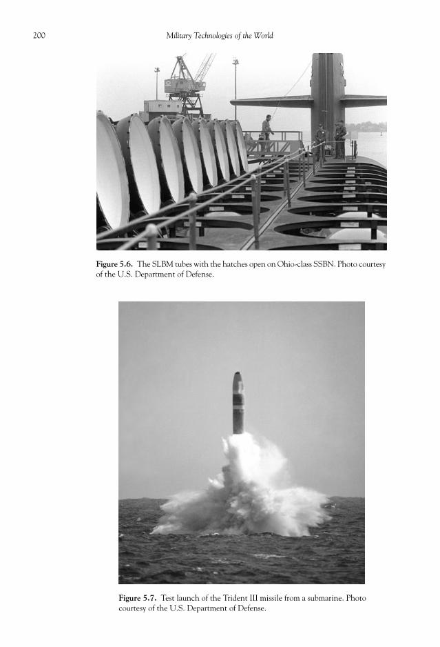
200 Military Technologies of the World
Figure 5.6. The SLBM tubes with the hatches open on Ohio-class SSBN. Photo courtesyof the U.S. Department of Defense.
Figure 5.7. Test launch of the Trident III missile from a submarine. Photocourtesy of the U.S. Department of Defense.

201Space Warfare: Nuclear Armaments and Missile Defense
tracks the missile acceleration and trajectory through-out the missile fl ight and maneuvers the fi nal fl ighttoward the targets using gimbaled liquid-fueled(monomethyl-hydrazine with nitrogen tetroxide)rocket motors. These gimbaled motors consist of sixpitch and yaw motors, along with four roll motors, sothey control the trajectory by adjusting all attitudeangles of the delivery vehicle. The current level ofaccuracy achieved through this guidance is within100 m of the target. During reentry into the atmo-sphere, the warheads along with decoys and chaff tomislead the radar surveillance are released in trajecto-ries toward separate targets (MIRV). Shortly after re-entry, the warheads are armed and may be detonatedas air or ground bursts depending on the mission.
The ground-based ICBMs constitute a part of thenuclear arsenal in most states, they have the followingcharacteristics:
Survivability: Low for silo-based ICBMs. Current accuracy of strikeweapons make fi xed-site ICBMs susceptible to pre-emptivestrikes.
Accuracy: The accuracy of a ballistic missile is measured by itscircular error probability (CEP). CEP is defi ned as the radius ofa circle centered at the target that the missile will strike with aprobability of 50 percent or better. Minuteman III has a CEP of220 to 275 meters depending on the reentry vehicle that is used.This is considered a high-level accuracy capable of knocking outhardened missile silos. Russia’s “Iskander” missile is believed tohave a CEP of less than 100 meters.
Time on target: ICBMs are ballistic missiles, meaning that theyattain a very high velocity during boost phase and mostly main-tain that velocity until impact. Thus, the transit time to targetis measured in minutes.
Table 5.4. Main Characteristics of U.S. ICBMs (Adapted from “The Future of Land-BasedStrategic Missiles”).
Launch Vehicle Minuteman II Minuteman III Minuteman IIIA MX
Length (m) 17.7 18.3 18.3 21.6Diameter (m) 1.7 1.7 1.7 2.3Weight (kg) 33,000 35,000 35,000 87,000Range (km) 11,000 11,000 11,000 11,000Number of stages 3 3 3 3Number of warheads 1 3 3 10Reentry vehicle Mark-11C Mark-12 Mark-12A Mark-21Warhead W56 W62 W78 W87Warhead yield (megaton) 1.2 0.17 0.35 0.3CEP (m) 370 220 220 90Silo maximum pressure (kPa) 133 ~ 200 133 ~ 200 133 ~ 200 133 ~ 200
Figure 5.8. An ICBM in a hardened silo. Photocourtesy of the U.S. Department of Defense.
Figure 5.9. Launch of MX ICBMfrom a silo. Photo courtesy ofthe U.S. Department of Defense.

202 Military Technologies of the World
Figure 5.10. B-83 nuclear bomb. Photo courtesy of the U.S. Department of Defense.
Figure 5.11. Airborne launch control system on an EC-135 Stratolifter aircraft. This control paneldecodes the launch instructions and remotely sends launch sequence commands to a ground-basedMinuteman III missile from the air. Photo courtesy of the U.S. Department of Defense.

203Space Warfare: Nuclear Armaments and Missile Defense
The latter two factors favor the use of the ICBMs, though the low survivability has ledto the development of alternate strike or counterstrike capabilities through airborne orsubmarine-launched nuclear weapons. For this reason, the submarine launch capability isan important asset in the nuclear arsenal.
The naval nuclear arsenal now involves tactical nuclear-tipped cruise missiles and stra-tegic SLBMs. Due to the size and launch requirements for SLBMs, it is not hard to imag-ine that such concepts initially met with much resistance, both inside and outside theU.S. Navy. The fi rst proposed SLBM was called a “Jupiter” rocket, and it was 90 feet longand 95 inches in diameter. Adding to its size was the fact that Jupiter rockets were liquid-fueled. However, by the late 1950s a number of factors started to favor the developmentof a viable submarine launch capability. The most important one was the realization wasthat with the buildup rate of nuclear arsenal in United States and Soviet Union bothstates would have suffi cient nuclear strike capabilities to wipe out major targets, includingthe land-based launch sites, many times over. As noted previously, the airborne deliverycapabilities must be delivered on “launch on warning” basis to avoid being destroyed onthe ground. However, submarines submerged deep in the ocean with a communicationlink to the command base could in principle provide a means to deliver counterattacks.Technologically, guidance systems have been developed that are more accurate, reliable,and compact in size and weight (by the MIT Instrumentation Laboratory). Also, reliable,high specifi c-impulse solid propellants were becoming available. These developments ledto the “Polaris” SLBM program with an initial goal of developing a delivery capability for1-Mt (megaton) warhead over 1500 miles. During development, these goals were slightlydowngraded, resulting in the Polaris A-1, with a 600-kt warhead (W-47) and a range of1200 miles.
The development work for the launch submarines was performed in parallel, and exist-ing submarines were modifi ed to allow for housing, protection, and launch of the Polarismissiles. The method to eject the SLBMs out of the missile tubes on submarines involvesa “cold” launch. A high-pressure compressed air system is used to punch the missiles out ofthe tubes and to the surface of the water. Prior to the launch, the hard hatches coveringthe tubes are opened exposing only a thin diaphragm between the water and the missiletube. The missile tube is pressurized to the water pressure outside, then at launch the dia-phragm is explosively removed, and the missile is out of the tube with the high pressureair. To minimize the shock from the launch, the missile tubes are suspended on top of oil-fi lled shock absorbers. The fi rst submarine to carry nuclear SLBMs was the George Wash-ington, originally an attack submarine modifi ed for this purpose.
The Polaris missile program went through several rounds of improvements before thePoseidon missiles replaced them by 1972. The Poseidon C-3 had a length of 34 feet, arange of up to 3200 miles, and had a larger payload capability (up to 10 MIRVs with a40-kt warhead each). The modern SLBM deployed by United States and also the BritishRoyal Navy is the Trident series, carried by Ohio-class submarines. Trident missiles aremade by U.S. Lockheed Martin Space Systems under contract with the U.S. Departmentof Defense but have been made available to the Royal Navy under an agreement datingback to 1960s. Exchange of strategic missiles of this level of capability and sensitivity is anindicator of the close political and military relationship between the two nations. TheTrident missiles cover a range up to 7000 miles with a total yield of 3.8 megatons carriedby up to eight MIRVs. The missile guidance is again via inertial tracking, but while themissile is in outer space it is also able to use celestial reference to correct its trajectories.Celestial reference is comparing the apparent positions of reference stars to locate the mis-sile latitude, longitude, and altitude. GPS guidance used in some versions improves theaccuracy to a CEP (circular error probability) of 90 m.

204 Military Technologies of the World
Currently, the U.S. Navy operates a fl eet of eighteen Ohio-class SSBNs (ballistic missilesubmarines), each carrying twenty-four Trident missiles with MIRVs. An estimated 50 per-cent of the U.S. nuclear strike capabilities are entrusted to this fl eet, due to the high surviv-ability of SSBNs. When their locations are under deep sea and not known, it is diffi cult toknock them out. Table 5.5 shows some of the major aspects of Ohio-class SSBNs. TheSSBNs obviously carry the Trident SLBMs but also have a capability to launch nuclear-tipped torpedoes. We will look at the details of these ships in a later chapter in this book.
NUCLEAR EARLY WARNING SYSTEM
Since the end of the Cold War and recent developments in the Middle East, the focus ofthe nuclear strategy (both on offense and defense) has somewhat shifted. This of course doesnot negate the need to maintain vigilance and capability to monitor the entire globe forsigns of nuclear missile launch. Due to the high speeds attained by ICBMs and SLBMs, theamount of time available to respond to a nuclear attack is in terms of minutes (typicallytwenty-fi ve minutes for ICBMs and fi fteen minutes for SLBMs). This makes it imperativethat any potential missile launch events be immediately detected, identifi ed, and communi-cated to the top levels. Because nuclear weaponry is in constant danger of being proliferated,the requirements become more severe and expansive to monitor the entire world for poten-tial use of nuclear weapons, particularly through avenues other than the traditional deliverymethods discussed previously. The missile defense program against conventional missile at-tacks has been controversial from the start, and a huge economic and technical investmenthas been and is being made. The missile defense technology will be discussed later in thischapter, and it begins with an ability to detect and track missile launches around the globe.
USSTRATCOM is entrusted with a daunting task of coordinating the nuclear strikecapability as well as global monitoring and developing ballistic missile defense technolo-gies. Its mission statement reads:
USSTRATCOM is a global integrator charged with the missions of full-spectrum globalstrike, space operations, computer network operations, Department of Defense informationoperations, strategic warning, integrated missile defense, global C4ISR (Command, Control,
Table 5.5. Major Characteristics of Ohio-Class Ballistic Missile Submarines (Source: www.navy.mil)
Builder General Dynamics Electric Boat DivisionPropulsion Single nuclear reactor, single shaftLength 560 ftWidth 42 ftDisplacement 19,000.1 metric tons when submergedSpeed 23 mphCrew 15 Offi cers, 140 EnlistedArmament 24 tubes for Trident I and II, Mk-48 nuclear-tipped torpedoes in 4 torpedo tubesBase Bangor, WA, and Kings Bay, GAFleet USS Henry M. Jackson (SSBN 730), USS Alabama (SSBN 731), USS Alaska
(SSBN 732), USS Nevada (SSBN 733), USS Tennessee (SSBN 734), USSPennsylvania (SSBN 735), USS West Virginia (SSBN 736), USS Kentucky(SSBN 737), USS Maryland (SSBN 738), USS Nebraska (SSBN 739), USSRhode Island (SSBN 740), USS Maine (SSBN 741), USS Wyoming (SSBN742), USS Louisiana (SSBN 743)
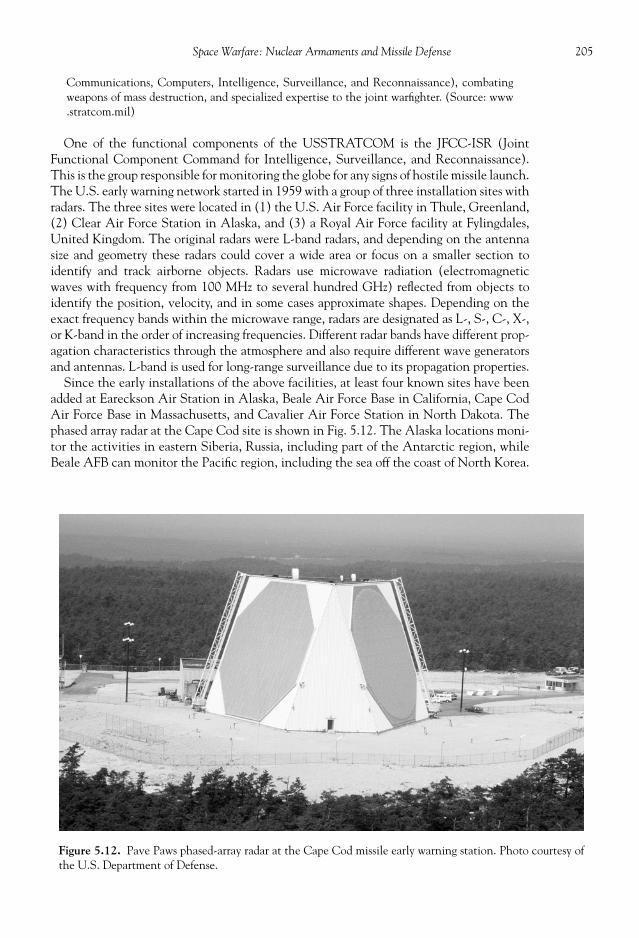
205Space Warfare: Nuclear Armaments and Missile Defense
Communications, Computers, Intelligence, Surveillance, and Reconnaissance), combatingweapons of mass destruction, and specialized expertise to the joint warfi ghter. (Source: www.stratcom.mil)
One of the functional components of the USSTRATCOM is the JFCC-ISR (JointFunctional Component Command for Intelligence, Surveillance, and Reconnaissance).This is the group responsible for monitoring the globe for any signs of hostile missile launch.The U.S. early warning network started in 1959 with a group of three installation sites withradars. The three sites were located in (1) the U.S. Air Force facility in Thule, Greenland,(2) Clear Air Force Station in Alaska, and (3) a Royal Air Force facility at Fylingdales,United Kingdom. The original radars were L-band radars, and depending on the antennasize and geometry these radars could cover a wide area or focus on a smaller section toidentify and track airborne objects. Radars use microwave radiation (electromagneticwaves with frequency from 100 MHz to several hundred GHz) refl ected from objects toidentify the position, velocity, and in some cases approximate shapes. Depending on theexact frequency bands within the microwave range, radars are designated as L-, S-, C-, X-,or K-band in the order of increasing frequencies. Different radar bands have different prop-agation characteristics through the atmosphere and also require different wave generatorsand antennas. L-band is used for long-range surveillance due to its propagation properties.
Since the early installations of the above facilities, at least four known sites have beenadded at Eareckson Air Station in Alaska, Beale Air Force Base in California, Cape CodAir Force Base in Massachusetts, and Cavalier Air Force Station in North Dakota. Thephased array radar at the Cape Cod site is shown in Fig. 5.12. The Alaska locations moni-tor the activities in eastern Siberia, Russia, including part of the Antarctic region, whileBeale AFB can monitor the Pacifi c region, including the sea off the coast of North Korea.
Figure 5.12. Pave Paws phased-array radar at the Cape Cod missile early warning station. Photo courtesy ofthe U.S. Department of Defense.

206 Military Technologies of the World
The sites in Greenland and on the U.S. East Coast monitor the Atlantic and Europeanregion. The advanced radar systems called phased array radars are used in all of these in-stallations with a range close to 3000 miles radius. The global monitoring capability issignifi cantly enhanced by the military surveillance satellites. Satellites use a spectrum ofvisible and radar frequency waves to detect ground and air activities and also have theadvantage of being directly above or close to the areas of interest. In fact, there are severalknown incidents of false alarms for nuclear attacks that have been corrected using satel-lite-based data. The exact details of the technology in radar and satellite surveillance havebeen discussed in Chapter 4.
During the Cold War, the Soviets were not negligent in the race to build up their nu-clear arsenal or in developing an equally functional early warning system. Along with asuite of satellites in various orbital confi gurations (geostationary, high elliptical), the Rus-sians also have installed a group of radar bases. Table 5.6 shows the known radar installa-tions operated by Russia.
MISSILE DEFENSE
The nuclear early warning system was initially put in place to initiate counterstrikes basedon the launch scales of the opposing side. This network of radars will have another use, if themissile defense program produces viable anti-ballistic missile weapons, in setting off launchesof projectiles to shield the United States against incoming missiles. The concept of a com-prehensive missile defense encompasses huge scales (a former distant early warning line inNorth America stretched 3600 miles) and yet if successful can provide a safety net for theside that possesses it. On the other hand, the margin of error in the technology is minimal,where even a leakage of one or two ballistic missiles may be considered as a failure of thesystem given the consequences. The anti-ballistic missile capability on one side may promptthe other to attempt to saturate the defense system by increasing the number of availablenuclear weapons. In spite of these constraints, the United States, Russia, and several othernations possess some form of operational defense against short-range, tactical missiles (nu-clear or conventional). The United States, in particular, has invested a signifi cant amountof economic and human resources to develop defensive capabilities against long-rangeICBMs. The origin of this effort goes back many years. Several years after both the UnitedStates and the former Soviet Union amassed a sizable nuclear arsenal, the United Statesinitiated a program to develop ballistic missile defense in 1958. During the last decade of the
Table 5.6. Russian Radar Stations for Ballistic Missile Early Warning.
Location (Site Designation) Radars Operational Date
Olegngorsk (RO-1) Dnestr-M/Dnepr, Daugava 1976Mishelevka (OS-1) Dnestr-M/Dnepr 1976Balkhash, Kazakhstan (OS-2) Dnestr-M/Dnepr, Dnestr 1976Svastopol, Ukraine (RO-4) Dnepr 1979Mukachevo, Ukraine (RO-5) Dnepr 1979Pechora (RO-30) Daryal 1984Gabala, Azerbaijan (RO-7) Daryalt 1985Baranovichi, Belarus Volga 2002Lekhtusi Voronezh-DM 2006Armavir Voronezh-DM 2007

207Space Warfare: Nuclear Armaments and Missile Defense
Cold War, the Reagan administration unveiled a renewed plan to realize the missile defensecapability in a comprehensive and expensive research and development program publicizedas the “Strategic Defense Initiative (SDI)” or by its nickname “Star Wars.” In spite of theadministration changes since then, it still lives on amidst astronomical costs, politicaldebates, technical controversies, and also in continuous tests and demonstrations of thetechnology at limited but increasing scales. It seemed to be an ideal countermeasure for then-growing nuclear threats in the previous era of mistrust and uncertainty between the two su-perpowers. If the only certainty of a massive nuclear exchange was mutual assured destructionas well as the global collapse of the survivable environment, then what would be better thanbeing able to provide a shield against horrifi c weapons and yet be capable of wielding coun-terattack weapons under this umbrella? One element of the missile defense program thatcannot be ignored is that the Kremlin policy makers were greatly disturbed by this threat ofmissile defense, which may have led to changes in their military and political philosophy.The imbalance caused by one side being able to defend against the nuclear attack must havebeen a powerful destabilizing force.
One of the questions that emerge then is what exactly is the purpose of the missile defense?Many controversies concerning its technical feasibility, impact on economy, and priorities innational defense in the changing global scene continue. Indeed, as one may have seen thusfar in this book, many of the issues surrounding military technologies in national and globaldefense have become so complicated that an individual or a group of individuals may have areally diffi cult time synthesizing all of the effects and nuances of these systems. As organiza-tions grow, military or civilian, they develop a life of their own in the form of bureaucracy,philosophical fi xations, or visions. It takes a true visionary, and on top of it much training andthought in technical and political issues, to be able to guide an organization and on a largescale the nation and the world to an acceptable path. It is a luxury to be able to read anddebate the blatant mistakes made by past empires resulting in huge human suffering. We nowplay at much higher stakes. To quote Albert Einstein, “I do not know with what weaponsWorld War III will be fought. But World War IV will be fought with sticks and stones.”
In Chapter 2 of this book, it is noted that the fi rst guided missile, the German V-2, fl ew in1942. By the early 1960s, both the United States and the Soviet Union had multi-stage,long-range, ballistic missiles armed with nuclear warheads. This is indeed a quantum leap inhuman capability to destroy at a scale far surpassing any of the previous means. The abilityto shield against this capability would not be so rapid. In spite of the massive publicity associ-ated with the Ronald Reagan administration and the SDI, there were lesser-known researchprograms in both the United States and the Soviet Union to develop this logical response tothe missile threat. The U.S. Defense Advanced Research Projects Agency (DARPA) had a$1 billion project from 1958 to 1969 on various defense concepts and testing, as did theSoviet Union on a much smaller scale. The some of the technical challenges became quiteevident from the start. First, how do you identify a missile launch from a distance more than3000 miles away with a fair amount of certainty? Indeed, there are several incidents of falsealarm concerning nuclear missile launches that were judiciously averted. Second, by the endof the boost phase, which lasts all of three minutes or so of the missile trajectory, these mis-siles are ballistic—meaning that they are fl ying at speeds close to 15,000 mph. How do youtrack these missiles and also guide your own projectiles to meet these objects in outer spaceor in the upper atmosphere? In the subsequent development of the nuclear missile technol-ogy, multiple independently targetable reentry vehicles (MIRV) became the standard in theICBM warheads. A single missile now could become multiple targets, and to hide their tar-get trajectories the warhead platform could release decoys and chaff in addition to theMIRVs. So on top of being an extremely high-speed guidance game, now it becomes a num-bers game. Can you put up enough of these defense systems to counter a shower of these

208 Military Technologies of the World
incoming objects from the sky? By the latter statement, it also brings about the dollars issue.In many instances, using a $500,000 cruise missile on an isolated radar installation, for ex-ample, may be justifi ed due to the lives it may have saved in not having to risk piloted mis-sions to knock out the radar. However, when a program is sustained over several decadeswith astronomical expenditure, one has to weigh the implications of the technology devel-opment again on military, economic, and political grounds.
The anti-ballistic missile defense is to be distinguished from tactical missile defense forwhich operational systems currently exist, as in the U.S. Patriot, the U.S. Standard SM-3,and the Israeli Arrow missiles (see Fig. 5.13). The Patriot is a tactical missile defense sys-tem for short- to intermediate-range missiles that made its debut during the 1991 GulfWar and progressively has gotten better in its reliability. The Navy’s Standard SM-3 also
Figure 5.13. A test launch of the Arrow anti-ballistic missile. Photo courtesy ofthe U.S. Department of Defense.

209Space Warfare: Nuclear Armaments and Missile Defense
defends against medium-range tactical missiles by providing a shield for the carrier-basedtask groups. The Arrow missile system is a joint project between the United States andIsrael that has the potential for intercept capabilities at longer ranges.
As shown in the Fig. 5.14, ICBMs trajectories are characterized by three phases: (1) a boostphase where the rockets are fi ring and thus give off easily detectible infrared signatures; (2)
Figure 5.14. Flight phases of an ICBM.
Figure 5.15. A map showing the general coverage of the Russian ballistic missileearly warning system. Photo courtesy of the U.S. Department of Defense.

210 Military Technologies of the World
the mid-course phase, the longest duration of the missile trajectory involving a free fl ightin the outer space; and (3) the short re-entry phase where the missiles and decoys are de-ployed in their fl ights to the targets. The defense system can in theory be deployed duringany phase of the missile trajectory, and the system itself can be ground-based or somethingthat is operating in the air or even outer space from a satellite platform in orbit. The sys-tem must contain components of an early detection/identifi cation and ballistic missileinterception/kill. A number of kill methods have been proposed for knocking out ballisticmissiles in fl ight: (1) laser-beam weapons; (2) particle-beam weapons; (3) kinetic-energyprojectiles or rail guns; and (4) guided missiles. Lasers are used in devices ranging from CDplayers and barcode readers to optical diagnostics and industrial machining. The word“laser” stands for l ight a mplifi cation by s timulated e mission of r adiation. It is a methodthrough which lasing molecules contained in a “laser cavity” are made to act in unison to
Figure 5.16. An artistic rendition of the Russian GALOSH anti-ballistic missile.Photo courtesy of the U.S. Department of Defense.

211Space Warfare: Nuclear Armaments and Missile Defense
produce intense, monochromatic (single or few wavelengths) light. Laser beams are lightwaves, so they travel at the speed of light. Particle beams are ions (atoms with plus orminus an electron or two) or neutral atoms accelerated to extreme speeds so that theircombined kinetic energy can penetrate missile enclosures. Kinetic-energy projectiles areessentially bullets, except larger and much faster (as in 1000 times faster than rifl e bullets).One type of gun proposed to attain this kind of projectile speed is the rail gun using elec-tromagnetic forces for metal projectile acceleration. Finally, the guided missile is like otherguided missiles except it will have to have much higher speed and much more accurateguidance to have any realistic probability of intercepting and destroying a target movingat 15,000 mph.
After the ambitious declaration by the Ronald Reagan administration to develop anddeploy a missile defense system capable of dealing with a massive missile attack, the proj-ect objectives went through some revisions. By the time the Clinton administration tookoffi ce, the program was mostly focused on developing a ground-based mid-course defensesystem (or GMD). To give an idea as to the Clinton-era budget on the missile defenseprogram, $3.76 billion was allocated from GMD along with $500 million for boost-phaseand $200 million for terminal-phase research and development in the fi scal year 2002.Prior to this date, the budget for the missile defense program ranged from $1 to $5 billion/year. Within the lifetime of the “Star Wars” program from 1984 to the present, the totalexpenditure is estimated at $120 billion, and by the target deployment date the estimatedtotal amount to be poured into it is over $1 trillion. As a side note, some of the past greatempires have weakened themselves by over-expanding and spreading their military re-sources thin. The initial objective of the ground-based mid-course defense (GMD) systemwas to develop the capability of destroying fi ve ICBMs with fi ve warheads and low-techdecoys. Then the goals become progressively more extensive: to have the capability todestroy 25 ICBMs that deploy 25 low-tech decoys or 5 ICBMs + 5 warheads with 20 high-tech decoys before 2010. By 2010 to 2015, the goal increases to 50 ICBMs with 50 war-heads with low-tech decoys, or 20 ICBMs with 20 warheads + 100 high-tech (as of 2007)decoys, far short of the initial concept of defending the United States against an all-outnuclear attack.
The system that has received the most funding thus far is the ground-based mid-coursedefense system, with the initial objective of providing an effective defense against one ora few missiles launched against the United States. The anti-ballistic missile (ABM) de-fense system being tested in installations at Fort Greely, Alaska, and Vandenberg AirForce Base in California is an example of a GMD system. Thus far, the most recent threatof missile launch against the United States by a rogue state has been that of North Korea.They had the crude idea of bolting together a set of old Russian SCUD missiles and givingit their own name of “Taepodong-2.” The boosters were designed to ignite in sequence,much like multi-stage rockets. North Koreans, given to exaggeration, claimed a range of9300 miles, making the U.S. mainland well within its reach. However, during a publicizedtest fi ring of this missile on July 4, 2006, it crashed after a forty-two-second fl ight. In themeantime, the U.S. GMD tests have been ongoing with varied results. To be fair, the fi nalassessments should not be made of the program as of yet. The missile defense agency doesclaim that since 2005 sixteen out of the seventeen fl ight tests have been successful andthat the program has accumulated twenty-seven successful intercepts out of thirty-fourtest launches since 2001. However, the public is probably more aware of the failed testslike the “no test” in May 2007 when the target ICBM failed to arrive at the test area or thefailed launch of the intercept missile itself in December 2004 at the Marshall Islands in thePacifi c and again in February 2005 due to “software error.” As of now, the tests of anti-ballistic missiles have involved limiting the number of operational variables and gradually

212 Military Technologies of the World
relaxing these constraints as confi dence and technology is gained from the test. For ex-ample, initial tests involved the use of homing devices or electronic beacons installed onthe test target missiles, with the reason being that a complete surveillance system of satel-lites and radars to actually track target missiles is lagging in development. The MissileDefense Agency did report a successful hit-to-kill launch against two short-range missilesat an altitude of 100 km in April 2007 using a guided kinetic-energy missile. This demon-strated the tracking capability on isolated missiles (two of them in this case), although thespeed and altitude of the target missiles are far short of those of ICBMs. It was reported bythe Missile Defense Agency that the target missiles were destroyed three minutes after thelaunch at a range 250 miles downstream of the launch site.
The GMD consists of an array of interceptor missiles launched from the ground, and acomprehensive surveillance network involving spy satellites and ground-based X-bandradars (microwave at the 2.5- to 4-cm wavelength range) for accurate tracking. The sig-nals from the satellites and radars are transmitted to a command-and-control center, wheremassive computing facilities and software analyze the combined set of signals to determinethe identity and trajectory of any objects fl ying toward the United States. The GMD in-tercept missile itself is a conventional rocket with a two-stage booster and a fi nal liquid-fueled rocket engine used for intercept. Liquid-propellant rocket engines offer much morecontrollability in the thrust, simply by metering the fuel and oxidizer fl ows. These missileswill also reach a speed close to 15,000 miles per hour. Currently, the intercept missiles arenot equipped with warheads. Instead, they are designed to impact on the incoming missileand in that regard can be considered as a guided kinetic-energy projectile. As noted above,the main delay even in GMD appears to be in the lack of a reliable surveillance-identifi -cation system and in missile guidance involved in meeting a 15,000 mph missile in spacewith another 15,000 mph missile. A photograph in Fig. 5.18 shows the so-called “exoat-mospheric reentry vehicle interceptions system” under development. It is based on the
Figure 5.17. The GALOSH mobile launch vehicle. Photo courtesy of the U.S. Department of Defense.

213Space Warfare: Nuclear Armaments and Missile Defense
infrared target acquisition, and the cylinder at the top of the device is perceived to be a killenhancement device.
The mid-course intercept option is considered to offer the largest window of opportu-nity for the missile defense. Both the boost phase and terminal phases are very short, androcket propulsion technology is advancing to a point where the boost phase can be short-ened to less than two minutes. Also, to knock out a missile in its boost phase requires theintercept missiles to be in at least some proximity, and this is not always possible forground-based systems given the geopolitical constraints. The terminal phase also lasts twominutes at most, and current surveillance and analysis capabilities simply cannot completetheir tasks in this amount of time. Of course, by the terminal phase any error in analysis orintercept will lead to immediate consequences. The original goal of the missile defense
Figure 5.18. An exoatmospheric reentry vehicle interceptions system under develop-ment. Photo courtesy of the U.S. Missile Defense Agency.

214 Military Technologies of the World
serving as a massive umbrella against large-scale missile attack was somewhat far-fetchedeither out of misinformation or by design. The fact of the matter is that it is simply muchcheaper for the attacking side to devise decoys or other devices to defeat the missile de-fense system than try to put together a comprehensive missile defense system. It is believedthat Russia has warhead deployment schemes capable of overwhelming any conceivablemissile defense as of today. The Russian Topol-M ICBM, commissioned in 2005, has highspecifi c-impulse solid-rocket boosters, which shorten the boost phase to a point where theboost phase defense is nearly inconceivable. Along with hardened casing and refl ectivecoating to defl ect laser beams, the warhead consists of MIRVs and four high-tech decoys.The missile even has mid-course evasive capability. Other methods of target discrimina-tion include particle beams to check for the presence of fi ssionable material, laser beams,and kinetic-energy particle probes. The latter method checks the deviation of the objecttrajectory after the particle impact, to estimate the mass of the target.
One advantage of the boost-phase missile defense, however, is that it is deployed duringa phase where the missiles are relatively slow, and there will be clear infrared signature dueto the rocket plumes. In addition, the decoys or other diversionary devices are not yetbeing deployed. At least these are the justifi cations for proponents of the boost-phase in-tercept. Of course, one big question is how to tell whether the missile launch is for a be-nign placement of satellites or for a hostile attack involving nuclear warheads. Oneconcept, out of many, that has been proposed for the boost-phase defense is the use anairborne anti-missile laser placed on a modifi ed Boeing 747-400F. To penetrate throughthe missile casing, the required power was fi rst estimated at 1 million watts of laser energyfocused on essentially a fi xed spot on the missile. So not only must a laser beam of thismagnitude be generated on board the aircraft and penetrate the atmosphere, but also thebeam needs to be directed and tracked to follow the target missile. As we know on hotsummer days, light gets refracted by hot air over the road surface or the backyard grill. Thesame thing happens through the atmosphere. Any density or temperature change will alterthe beam trajectory, in spite of the fact the beam may be propagating at the speed of light.Any dust or cloud particles will trap some of the laser energy as well. With current lasertechnology, several SUV-sized laser modules need to be aligned to produce one giganticbeam, and this grouping of heavy lasers is estimated to test the limits of the Boeing 747-400F aircraft’s lift capability. Finally, such heavily-laden 747s will be indefensible.
An alternate concept is to place chemical lasers emitting infrared beams in low earthorbits at an altitude above 100 km. For these chemical lasers, the required laser output risesto the 1 gigawatt range or 1 billion watts. Also, to cover the large expanse of Russia alonewith a missile launch capability of up to 3000 ICBMs, a whopping 500 satellites carryingheavy lasers would be required at a cost of over $1 trillion just for these satellites. Othertypes of laser beams are also being researched, like short wavelength X-ray lasers, ultravio-let excimer lasers and geosynchronous orbiting mirrors, but all with equal or greater fun-damental diffi culties, at least insofar as a comprehensive anti-ballistic missile defense isconcerned.
As noted previously, particle-beam weapons use accelerated ions or neutral particles.These particles can penetrate deeper into the missile shields than photons generated bylasers. However, electrically charged ions are subject to forces of the earth’s electromag-netic fi eld and its fl uctuations. So the trajectory may become completely warped in unpre-dictable ways, more so than atmospheric turbulence may defl ect laser beams. To defeatthis effect, one concept that has been proposed is to fi rst accelerate the electricallycharged ions in an electromagnetic accelerator and attach electrons back to the ions asthey exit the accelerator, making them electromagnetically neutral. This then has theunwanted effect of being unusable in any atmosphere, as the collisions of these particles

215Space Warfare: Nuclear Armaments and Missile Defense
with atmospheric molecules will knock out the electrons and turn them back to ions. Inany event, the electromagnetic accelerators tend to be again bulky and require a lot ofpower. It is again estimated that to cover the Russian ICBM threat about 100 billion wattsof electrical power concentrated in time intervals of 50 to 100 seconds are needed.
A method called “Brilliant Pebbles” has also been proposed, which is an updated versionof the spaced-based interceptor idea back studied by the United States Air Force back in the1970s. In a project called “High Frontier,” it was proposed to place large satellite “trucks”that circle in orbit over the Soviet ICBM launch sites. Each truck was to carry forty-fi ve killprojectiles. At the level of technology in 1970, however, the interception would require 350seconds while the Soviet boosters of this period, the SS-18s, only had a boost phase lasting300 seconds. The 432 trucks proposed to be sent into the orbit with forty-fi ve kinetic projec-tiles each had the capability to shoot down only 12 percent of the Soviet ICBMs. This sat-ellite-based projectile method was resurrected as “Smart Rocks” in the 1980s and evaluatedat the Lawrence Livermore National Laboratory in northern California. It again involved alarge number, thousands, of small launch satellites dispersed in shallow earth orbits to aimand fi re rocket-propelled projectiles. In a series of computer simulations, a group of scientistsand engineers from the laboratory was able to convince the Reagan administration that thisconstellation of interceptor satellites, if realized and implemented, had the capability toprovide an umbrella against the full-scale nuclear attack. In 1988, the concept was upgradedto refl ect some advances in the technology and renamed “Brilliant Pebbles.” Through inter-mittent funding following the demise of the Soviet Union, it is still considered as the mostcost-effective method in comparison to other kill methods described above. Although mostof the missile defense work in recent years has been on ground-based (GMD) interceptormissiles, the Brilliant Pebbles idea continues to intermittently receive evaluations based oncurrent level of technology. Brilliant Pebbles involved a small satellite of approximately onemeter in length that could operate autonomously with independent sensor, inertial guid-ance, attitude/aim control thrusters, and a rocket canister for fi ring the kinetic-energy pro-jectile. At the time these concepts were proposed, the focus was on defense against full-scalenuclear missile launch by the former Soviet Union. To defend against 1000 nuclear missiles,it was estimated that some 80,000 of the Brilliant Pebbles satellites would be needed. Sincethese killer satellites would be in low earth orbit and have minimal temporal and spatialcoverage, a large number would be needed to fully cover the missile launch sites. Perhaps asthe shift has changed to theater defense against a much smaller number of threat launches,this concept may be revisited by the missile defense program.
COUNTERMEASURES TO ANTI-BALLISTIC MISSILE DEFENSE
One of the fundamental problems of the anti-ballistic missile defense is that effectivecountermeasures can be installed at a tiny fraction of the cost of any technology designedto defeat them. One obvious countermeasure is the use of decoys. Current ICBM payloadscontain decoys and balloons (to aid the reentry of the warhead), along with multiple war-heads. In outer space, there is close to zero resistance to object motion, so all these objectswill follow the trajectory as set by the missile at the end of the boost phase. ModernICBMs can carry up to 10 MIRVs per missile, and this capability can be enhanced to yetlarger number of MIRVs without too much technical diffi culty although current agree-ment is toward reducing the number of MIRVs. To assist during the atmospheric reentry,up to twenty balloons are enclosed per each reentry vehicle. These balloons have alumi-nized mylar surfaces to refl ect radar and appear as reentry vehicles on the radar. Thismeans that for a large-scale missile launch involving 1000 missiles, there could be as many

216 Military Technologies of the World
as 350,000 objects in the sky to track, identify, and shoot down. Since trying to shootdown all of these objects is futile, a key component of a missile defense is the target dis-crimination between warheads and non-warheads.
One method proposed is to use the infrared signatures of the warheads, as they will ab-sorb some of the heat of the boosters to an extent greater than the balloons. The heatedwarheads emit infrared radiation that may be sensed from long ranges. Again, the show-stopper is that balloons can easily be equipped with small heaters to give off thermal infra-red radiation equal to that of the warheads. Moreover, the warheads themselves can beinsulated to block out any thermal emission. A small amount of spray released from themissile can also shroud the infrared signature. Finally, for an infrared detector placed on asatellite, there would be a substantial amount of background infrared emission from theearth surface that could drown any perceivable signals.
The radar tracking of the warheads can also be eluded using a number of simple coun-termeasures. Aluminum chaff and smoke clouds are used in aircraft anti-missile systemsbecause they refl ect the incoming radar beams or absorb and scatter them. These can beeasily carried and deployed by ICBMs. The missile surface itself can be coated with eitherablative or refl ective material to absorb the anti-missile laser beam or refl ect it away. Evena small amount of protective coating will translate to a many-fold increase in the powerrequirements for the anti-missile defense devices, because they must overcome these bar-riers to ensure destruction of the warhead or the missile.
To defeat the boost-phase anti-missile systems, fast-burn boosters can be used to simplyshorten the boost time during which there will be quite a strong infrared signature fromthe rocket plume, and all of the warheads are contained within the missile. With improve-ments in the booster design and propellant, boost time can be shortened to less than aminute. This will severely limit the effectiveness of guided interceptor missiles againstthese objects. Fast-burn boosters can attain 80 km altitude in sixty seconds, by reducing itspayload mass slightly. Some solid-propellant boosters can reach 100 to 160 km heights inless than two minutes. In contrast, guided missiles move at a speed of about 10 kilometersper second, and it will take them more 100 seconds to reach a target 1000 kilometers away.For this reason, a mathematical analysis gives that the maximum kill area (the area thatthe guided interceptor missile can cover to score a kill) is proportional to the square of itsvelocity and also to the square of the time available: Amax = πv2 t2 . So if the burnout timeof the target ballistic missile is reduced by half, then the maximum effective area for theinterceptor missile diminishes to one-quarter of the original. Also, after the boost phase isover, if the guidance missile relied on thermal emission then it will be fl ying mostly blind.As shown in the above equation, one way to compensate for these fast-burn times of targetmissiles is to increase the interceptor missile velocity proportionately. However, to in-crease the speed of guidance missiles requires more propellant mass, actually quite a lotmore. To gain a two-fold increase in the maximum speed, a whopping twenty-eight timesincrease in the propellant mass, and therefore the missile rocket size, is required. In spiteof these diffi culties, there are efforts underway to devise interceptor missiles with substan-tially higher speeds, to the tune of Mach 10 or above.
Alternatively, the missiles can be launched to follow depressed trajectories below thehorizons of the early warning radars or satellite sensors. More thrust is required because themissile will fl y against higher atmospheric drag and also at a trajectory that does not makethe optimum use of the gravity, but SLBMs can compensate for the larger required thrustby moving closer to the target. The so-called minimum-energy ballistic trajectories followa path to achieve the needed altitude to fall to the target at a given range, and typical bal-listic missiles are programmed to follow this path. For example, for a 1500-km range targetthe missile boost phase may last about sixty seconds, at which time the missile altitude

217Space Warfare: Nuclear Armaments and Missile Defense
would be 58 km. For the missile following a minimum energy trajectory, it will have totravel for another 482 seconds (8 minutes and 2 seconds) to reach the target. If the trajec-tories are depressed, then this fl ight time can be 40 percent less. If an interceptor missile todefeat this ballistic missile had a speed of 2.0 km/s (1.25 miles/s) and range of 500 km fromits point of launch, then it would require approximately 313 seconds to reach the target.For the minimum energy trajectory, the window of opportunity exists assuming that allgoes as projected, but for the depressed path the time window is minimal or nonexistent.
The critical time factor is further encumbered by the fact that missile intercept must fol-low a series of protocols. The sequence of events leading to the launch of the intercept mis-sile begins from the satellite, radar, or airborne sensor detecting the launch of a threat missile.A number of radar hits by a single or multiple radars are needed to confi rm the direction andcharacteristics of the threat missile. Next, the optimal interceptor missile type and launchsite are assigned based on the threat missile identifi cation, at which point the radar trackdata are downloaded to the launch computer. The fi re control radar at the selected launchsite then takes over the tracking and proceeds to launch the interceptor missile. The trajec-tories of the threat and intercept missiles are tracked for possible mid-course corrections andfor kill confi rmations. The time available for the above sequence is two to fi fteen minutesdepending on the missile range. For the minimum energy trajectories mentioned earlier, a3000 km range is covered in 14 minutes, 2000 km in 11.48 minutes, 1000 km in 8.23 min-utes, and so on, with the depressed trajectories again taking much less time.
Another imbalance in this numbers game is that the missile defense can be overwhelmedby an increased number of missiles and accompanying decoys. In addition to the infra-structure cost to build the surveillance and target discrimination hardware and software, itcosts much more to build the missile defense satellites or other systems than to increasethe offensive weapons arsenal. A conservative estimate is about $25 million to add a newICBM against $1 billion for one missile defense satellite. Finally, putting the missile de-fense systems in place does not ensure their continuous operation. Satellites, aircraft, orground-based missile defense systems themselves can be attacked, and a nuclear attack onsky or ground targets cannot be ruled out. In fact, there is a perception among some ex-perts that the missile defense systems either by design or by deceit may be put to muchmore effective use against satellites. It would require quite an advanced technology toknock out indiscernible objects traveling in outer space at 15,000 miles per hour, but incomparison satellites or ground-based radar and communication systems, whether they arelinked to the nuclear offensive capabilities or not, would be sitting ducks against knock-out punches delivered by some of the concept weapons discussed above. This is perhapsthe true battleground for the future space warfare technology.
ANTI-SATELLITE WARFARE
Satellites are now closely linked with the way civilized society operates. Live TV broad-casts of events occurring anywhere in the world, even real-time battlefi eld reporting as inthe Iraqi War that began in 2003, are now taken for granted. Flow of information and fi -nancial, diplomatic, and global news occurs through satellite links. Earth-observing satel-lites monitor surface meteorology, pollution, land use, water, and other resources. Theglobal positioning system, fi rst developed for military use including missile guidance, isbecoming a daily necessity in navigating an automobile on less familiar roads.
The satellites may be categorized by their functions or by their orbital altitude. So-calledlow earth orbit (LEO) satellites up to an altitude of 2000 km include mobile communicationsatellites like the Globalstar, Gonets, Iridium, and Orbcomm. Other civil, military, and

218 Military Technologies of the World
commercial imaging satellites also fall in this category. There are also an estimated fi fty or somilitary early warning satellites in this orbital range, like the FSW, Helio, Jump-sea, La-crosse, and Tselina series for intelligence and photoreconnaissance. Other military applica-tions of LEO satellites include defense meteorology, navigation, tactical communications,and technology development. The medium earth orbit (MEO) refers to the range of altitudeabove 2000 km but below the geosynchronous orbit of 22,236 km. The NAVSTAR GPSsystem of twenty-four satellites operated by the U.S. Air Force operates in the MEO range.Finally, at an altitude above 22,236 km the satellites can be induced to move at the samespeed as the earth rotation and thus the name geosynchronous or geostationary earth orbit(GEO). Commercial communication satellites are sent to these orbits for telephone, broad-casting, video, and data transfer functions.
As discussed in Chapter 4, sensors on the satellites for military purposes have becomehighly sophisticated. A large part of the electromagnetic spectrum, ranging from visibleand infrared to microwave, is used to detect and identify military activities. A large mag-nifi cation imaging system looking down on earth, aided by computer image processing,allows identifi cation of objects less than 1 m. Missile defense itself is closely supported bysatellite surveillance. A large fraction of these military and civilian operations nowadayswill be rendered blind if these satellites were put out of commission. Moreover, some of themissile kill devices under development are designed to be placed in orbit, in the same al-titude range as most of these satellites. It would be a relatively simple matter to point andshoot at the relatively slow-moving satellites in the vicinity.
Military operations are more and more dependent on satellites. Surveillance, communi-cation, and guidance are provided by satellite signals. Unmanned aerial vehicles (UAVs)like the Predator and the Global Hawk require satellite-guided navigation for their fl ights.The U.S. military operates over 500,000-plus GPS receivers linked with signal-generatingsatellites on cruise missiles, precision-guided bombs, and battlefi eld management devices.GPS consists of twenty-four or more satellites in medium earth orbit (12,600 to 14,760miles above the earth), and these satellites send out time signals based on onboard atomicclocks with high accuracy. The receiver reads and compares the time signals from at leastthree satellites, whose positions as a function of time are in the data base. Knowing thedistances to these satellites at known positions allows the calculation of altitude, latitude,and longitude to within about fi ve meters or better.
In all, more than 800 satellites are used for military and commercial purposes accordingto an estimate made in 2005. Nearly half of these are operated by the U.S. government orprivate sector. The functions of these satellites range from meteorological observations,earth surface remote sensing, and audio-video communications to military surveillance. Acommunication satellite in a geosynchronous orbit moves around the earth in a twenty-four hour cycle at an altitude of 22,237 miles. This orbital motion translates to a speed of1000 miles per hour, just a fraction of the ICBMs 15,000 mph speeds. Other satellites maybe moving at higher speed but at a much lower altitude down to a few hundred miles, likethe military surveillance satellites at 100 to 240 miles above the earth. Moreover, for thesatellites to be useful they must follow a precise, predictable orbit around the earth. Anyone of the missile defense weapons can be used to track and knock out these satellites,numbering in the hundreds, to cause serious disruptions.
BEAM WEAPONS
The entertainment media and the public have had a long history of fascination withlaser or beam weapons. Numerous comics and comics-like movies have shown ray guns or

219Space Warfare: Nuclear Armaments and Missile Defense
beam weapons, probably the most notable ones being the light sabers and an assortmentof blasters in the Star Wars series. This notion was actually used in earlier science fi ctionslike “The War of the Worlds” by H.G. Wells in the 1890s, in which Martians were armedwith “heat rays.” In it, the Martians are described as “able to slay men so swiftly and sosilently” using a device “to generate an intense heat in a chamber of practically absolutenon-conductivity.” An actual use of directed beams may have been used way back in 212BCE. Archimedes, the Greek genius mathematician and engineer who did everything fromfi guring out the density of metals to inventing siege and anti-siege machines, used large,curved mirrors to focus sunlight onto the invading Roman ships perhaps to ignite the sailand other combustible material on board. Although this was insuffi cient to stop the inva-sion, and in fact Archimedes was killed during this attack when he refused to disengagefrom a mathematical problem according a legend, this is perhaps the earliest known use ofbeam weaponry.
The discovery of lasers in the 1950s was made nearly simultaneously by American andSoviet scientists, Charles H. Townes and Arthur Schawlow of Columbia University andNikolai G. Basov and Aleksander M. Prokhorov of Lebedev Physics Institute in Moscow.Laser works by electronic energy in high-energy atoms or molecules being released whenthe atoms or molecules return to low-energy state. The energy release occurs through giv-ing off photons or light, which is made much more effective when this light is induced tobounce back and forth in a cavity. This sweeping motion of photons induces yet more re-lease of photons of the same energy (or wavelength), resulting in amplifi cation of the lightemission. In fact, this is where the term “laser” originated; as previously mentioned, it’sactually an acronym for l ight a mplifi cation by s timulated e mission of r adiation. A largenumber of materials can be used to generate lasers, and the energy states of the constituentatom or molecule then determines the output wavelength of the laser. An external energysource is needed to send the laser material atoms or molecules to higher energy state, andthis is accomplished by using fl ash lamps or in some cases another laser!
The utility of lasers was not lost to the military, and the commercial sector soon caughton as well. From industrial lasers used for laser machining and welding and laser range-fi nder scopes down to CD players, lasers are ubiquitous in modern engineered products.The United States military has had an interest in lasers as beam weapons from early on. Acarbon dioxide laser was developed under a Pentagon contract to reach a power level of60,000 W. Chemical lasers were discovered in the early 1960s, and this type of lasers hada potential for a much higher power output. Chemical lasers excite the lasing moleculesfrom internal chemical reactions, not external light sources like the fl ash lamps. If we burnfuel and oxygen, the net thermal energy increases, raising the temperature. This type ofchemical reaction is called an exothermic reaction. For some reactants, such exothermic-ity can generate heat and high-energy atoms or molecules that can again be used as lasingmaterial. For example, in an oxygen-iodine chemical laser, the laser cavity is fed withgaseous chlorine, molecular ions, and a mixture of hydrogen peroxide and potassium chlo-ride. The ensuing chemical reactions produce excited oxygen and iodine, and it is iodinethat emits photons through stimulated emission at the 1.315 μm wavelength (infrared).The chemical lasers had the advantage of being easy to scale up and continuous feeding ofthe reactants to replenish the lasing material. A large-scale chemical laser was built andtested by the Rocketdyne Division of the Rockwell International Corporation at a remotesite that delivered a laser output of 100,000 watts in 1977. As early as 1978, the U.S. Navyused a chemical laser to shoot down a small anti-tank missile in a test range, perhaps serv-ing as a precursor to the later rush to develop anti-ballistic missile lasers.
A class of lasers called “excimer” lasers contains xenon or krypton with halogen atomslike chlorine and fl uorine. When these atoms combine to from xenon chloride, krypton

220 Military Technologies of the World
fl uoride, and so forth, they become electronically excited. Krypton is not a magic element(as in “kryptonite” in the Superman comics) but a naturally occurring element. The en-ergy to form the above excimer compounds come from electrical discharge or electronbeams. Since the excimers are electronically excited, they are unstable, and during a re-verse reaction into separate atoms they release photons or laser light. The unique aspectof excimer lasers is that they are capable of high-power output in the ultraviolet range. Aconcept that has been entertained was using a ground-based excimer laser at a mountain-top site and using satellite mirrors in orbit to refl ect and direct the beams to targets. How-ever, atmospheric effects such as beam refraction and absorption by ozone layer make sucha realization diffi cult.
A far-fetched concept of generating powerful laser beams involves a nuclear bomb andX-ray lasers. This concept uses the energy of a nuclear bomb explosion to power X-raylaser rods. The energy is suffi cient to generate something like fi fty extremely powerfulX-ray laser beams to be centered onto multiple targets. Once the nuclear bomb is ex-ploded, the X-ray laser rods of course become a single-use component. In fact, the result-ing X-ray will be on its path as set by the initial alignment of the laser rod, followed by thedebris of the nuclear blast.
These beam weapons use photon beams (i.e., light beams). Other particles can also beaccelerated to carry suffi cient kinetic energy. Electrically charged particles like electrons orions (atoms with one or more defi cit or surplus electrons) can be accelerated in electric orelectromagnetic fi elds. Opposite charges attract, and therefore positive ions for examplewill be drawn to the negative electrodes (cathodes) in an electric fi eld. In contrast to therelative ease with which charged particles can be accelerated, their kinetic energy can alsobe rapidly dissipated through collision with other particles, like the atmospheric molecules.That is why electron-drive devices like the old-fashioned TV screens operate in a vacuum.In addition, charged particles are subject to the earth’s magnetic fi eld and other electromag-netic disturbances, making their fl ight control extremely diffi cult. To circumvent the lattereffect, neutrally charged particle beams have been considered. The ions (e.g., positive hy-drogen ions) are accelerated in alternating electric fi elds. First, the electrode is charged tonegative bias, attracting the hydrogen ion, and as the hydrogen ion passes through theelectrode, it reverses its charge to positive to repel the ion. The next set of electrodes willundergo the same precisely timed sequence. The total voltage used in this accelerator mayexceed 1 billion volts, and the resulting velocity of the ions is close to the speed of light.The ions are then passed through a chamber fi lled with a small amount of gas. During thepassage of the accelerated ions in this chamber, the electrons are drawn to the positive hy-drogen ions to make the particles electrically neutral. The ion particles then proceed ontheir paths toward the target at extreme velocities and in neutral charge states.
REFERENCES
Hecht, Jeff. Beam Weapons: The Next Arms Race . New York: Plenum Press, 1984. Levi, B.G., M. Sakitt, and A. Hobson (eds.). The Future of Land-Based Strategic Missiles . New York:
American Institute of Physics, 1989. Pahl, David. The Space Warfare and Strategic Defense .Winnipeg, Canada: Bison Books, 1987.For further information on Reagan’s “Star Wars” program, see www.fas.org/spp/starwars/program/ nmd.

MILITARYTECHNOLOGIES
of the WORLD

Praeger Security International Advisory Board
Board Co-chairs
Loch K. Johnson, Regents Professor of Public and International Affairs, School of Publicand International Affairs, University of Georgia (U.S.A.)
Paul Wilkinson, Professor of International Relations and Chairman of the AdvisoryBoard, Centre for the Study of Terrorism and Political Violence, University ofSt. Andrews (U.K.)
Members
Anthony H. Cordesman, Arleigh A. Burke Chair in Strategy, Center for Strategic andInternational Studies (U.S.A.)
Thérèse Delpech, Director of Strategic Affairs, Atomic Energy Commission, and SeniorResearch Fellow, CERI (Fondation Nationale des Sciences Politiques), Paris (France)
Sir Michael Howard, former Chichele Professor of the History of War and RegisProfessor of Modern History, Oxford University (U.K.), and Robert A. Lovett Professorof Military and Naval History, Yale University (U.S.A.)
Lieutenant General Claudia J. Kennedy, US Army (Ret.), former Deputy Chief of Stafffor Intelligence, Department of the Army (U.S.A.)
Paul M. Kennedy, J. Richardson Dilworth Professor of History and Director,International Security Studies, Yale University (U.S.A.)
Robert J. O’Neill, former Chichele Professor of the History of War, All Souls College,Oxford University (Australia)
Shibley Telhami, Anwar Sadat Chair for Peace and Development, Department ofGovernment and Politics, University of Maryland (U.S.A.)
Fareed Zakaria, Editor, Newsweek International (U.S.A.)

MILITARYTECHNOLOGIES
of the WORLD
VOLUME
2
Praeger Security InternationalWestport, Connecticut • London
T.-W. LEE

Library of Congress Cataloging-in-Publication Data
Lee, T.-W. (Tae-Woo)Military technologies of the world / T.-W. Lee.
p. cm.Includes bibliographical references and index.ISBN 978-0-275-99535-5 (set : alk. paper) — ISBN 978-0-275-99537-9 (vol. 1 : alk. paper) —
ISBN 978-0-275-99539-3 (vol. 2 : alk. paper)1. Military art and science—Technological innovations—History. 2. Weapons systems—
History. 3. Military history. I. Title.U39.L42 2009623—dc22 2008034976
British Library Cataloguing in Publication Data is available.
Copyright © 2009 by T.-W. Lee
All rights reserved. No portion of this book may bereproduced, by any process or technique, without theexpress written consent of the publisher.
Library of Congress Catalog Card Number: 2008034976ISBN: 978-0-275-99535-5 (set)
978-0-275-99537-9 (vol 1)978-0-275-99539-3 (vol 2)
First published in 2009
Praeger Security International, 88 Post Road West, Westport, CT 06881An imprint of Greenwood Publishing Group, Inc.www.praeger.com
Printed in the United States of America
The paper used in this book complies with thePermanent Paper Standard issued by the NationalInformation Standards Organization (Z39.48-1984).
10 9 8 7 6 5 4 3 2 1

VOLUME 1
1. Air Superiority 1
2. Missile Technology 63
3. Helicopter Force 107
4. Stealth, Intelligence, and Surveillance Technology 139
5. Space Warfare: Nuclear Armaments and Missile Defense 189
VOLUME 2
6. Of Guns and Cannons 221
7. Fortress on Wheels: Main Battle Tanks 253
8. Modern Armada 287
9. Submarines 319
10. Perspectives on Military Technology 363
Index 371
Contents

This page intentionally left blank

GUNS AND CANNONS have always symbolized the force that can be wielded by anindividual soldier or by an army. Although other projectiles like missiles and torpedoeshave typically become the fi nal punch that delivers the destructive blow in modern war-fare, guns and cannons have been the main armament of military forces for a long time inhistory. If we look at the conventional battle situations involving main battle tanks andground troops, better guns would still give the edge to the side possessing them. Onceconsidered obsolete in aircraft and naval vessels, all modern jet fi ghters now carry can-nons; and for naval vessels specialized use of rapid-fi re guns is needed for a close-in weap-ons system against incoming missiles. In tanks and attack helicopters, integrated gun systemsare an important element of the armament.
As has been proven time and again, in spite of the advances in precision bombing andother high tech weaponry, conventional warfare requires the ground troops to make contactwith the opposition, advance, and control physical space. For such troop engagements, themain weaponry is of course personal rifl es assisted by an assortment of gunnery, starting fromgrenade launchers, machine guns, and mortars to high-caliber artillery. Indeed, the militaryhistory of the world is full of turning points in gun or cannon technology that have led todramatic shifts in the course of history itself. Many battles were won by the side able to adoptbetter and more powerful gunnery, and many peoples befallen due to lack of them.
The history of the gun starts in China. “Black powder” was invented before 900 CE inChina, most probably by alchemists who tried to mix different substances to formulate themagic substance. In Europe, the magic substance may have been gold, but in China thealchemists sought an elixir of immortality. When saltpeter, sulfur, and carbon of charcoalwith honey were mixed together, however, what they found was an explosive mixture thatburned their faces. The mysterious and explosive nature of this mixture soon found quitea different use than initially sought. It was used by the Chinese army to make crude fl amethrowers (“fi re lance”), grenades, siege weapons, and other devices that delivered shockeffects against the Mongols in the tenth century. Mongols in turn quickly adopted thetechnology and used it during their vast conquests of the Arab world and parts of Europe.There are references to its existence in Chinese documents dated as far back as 850 CE , andanother Chinese document, “Wu Jing Zong Yao” (“Collection of the Most ImportantMilitary Techniques”), contains three different recipes for black powder—two for incendi-ary bombs to be used during siege and one for propelling bombs. There is scattered evi-dence of substances similar to black powder in India dating as far back as fourth centuryBCE , but they are not as well substantiated as the Chinese historical documents.
CHAPTER
6
OF GUNSAND CANNONS

222 Military Technologies of the World
A systematic military use of black powder is believed to have occurred in Kai Fung Fu,China in 1232 CE through rack-launched bamboo rockets described as “arrows of fi re.”Chinese also developed cannons and used black powder to launch projectiles. When Mon-gols conquered China in the 1270s and acquired the technology, the use of cannons androckets powered by black powder became widespread in East Asian warfare. To the west,the Mongols advanced as far as Vienna, and to the east they invaded Japan using the navalknow-how of the Koreans under Mongol rule by thirteenth century. Although the invasionitself was doomed by a fi erce storm, the “divine wind” (kami-kaze), they left a record ofcannon-fi red explosive shells. The cannon was referred to as “teppo,” or literally “largegun,” and cannons are still referred to as teppo (Japanese) and Daepo (Korean). In thesunken vessels dating back to this invasion, such cannon shells have been discovered.
The Arabs, being connected to Asia by the Silk Road and also having been overrun by theMongols, learned of the black powder in thirteenth century. The Turks built an enormouscannon of 90 cm bore that fl ung 320 kg cannonballs over a mile. A Syrian named al-Hasan ar-Rammah describes in a book called Book of Fighting a rocket device for militaryuse that he called “Chinese arrow.” In 1325, the Arabs used gunpowder-propelled projec-tiles during an attack on the Spanish town Baza. The fi rst Arabian cannon, called “mad-faa,” was essentially a wooden bowl with the cannon ball balanced on the muzzle. Theexplosion of the gunpowder popped the cannon ball. During these periods, metallurgy haddeveloped to a level that allowed casting or other form-shaping to be used for cannonmaking. The next Arabian cannon, “pot de fer,” was again bowl-shaped but made of ironwith the projectile made of stone or lead. Other cannons of this time, however, were madeof wood reinforced by iron belts, much like wooden barrels. Europeans quickly adoptedthis technology from exposure to the Arabs, and in Florence manufacturing of cannonsand cannonballs began in 1325 almost immediately following the Arab use. In Europe, theuse of black powder was predominantly in guns and cannons, which developed rapidlythrough the inventiveness and availability of metallurgical know-how of the time. Onintroduction in Europe the use of the black powder was almost exclusively toward gun-nery, to fi re projectiles from long barrels such as muskets and cannons, hence the commonname “gunpowder” when referring to black powder. This was a natural development of theperiod because the only practical way to accurately guide the pellet trajectory was throughthe long muzzle of muskets. Here, we need to start distinguishing between guns that wereused as personal fi rearms and cannons that delivered much larger-caliber projectiles.
THE STORY OF GUNS
The fi rst type of gun in medieval Europe was called “gonne” or “culverine” and was es-sentially a small cannon that held the gunpowder and the ball. It was handled by two men,one holding the small cannon lashed to a stake and the other using a match to ignite thegunpowder. Later, a smaller one-man gonne was made for which the gunner had to lightthe gunpowder using a match with one hand, while holding the gun in another. In thebeginning of the fourteenth century, the fi ring mechanism was somewhat improved wherethe gunner held a lit wick against the gunpowder charge in the fl ash pan to ignite the maingunpowder. The lit wick, or slow match, was made by boiling a thin rope in lye and gun-powder. Once lit, the slow match smoldered along the rope. The fl ash pan was simply asmall chamber connecting the main gunpowder charge to the outside so that the lit wickcould make contact. Once the gunpowder in the fl ash pan was ignited, the fl ame wouldpropagate into the main charge, fi ring the bullet. This method made it nearly impossibleto hold a steady aim and was in general very cumbersome.
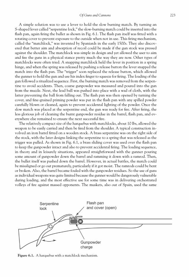
223Of Guns and Cannons
A simple solution was to use a lever to hold the slow burning match. By turning anS-shaped lever called “serpentine lock,” the slow-burning match could be inserted into thefl ash pan, again fi ring the bullet as shown in Fig. 6.1. The fl ash pan itself was fi tted with arotating cover to prevent exposure to the outside when not in use. This fi ring mechanism,called the “matchlock,” was invented by Spaniards in the early 1500s. They also discov-ered that better aim and absorption of recoil could be made if the gun stock was pressedagainst the shoulder. The matchlock was simple in design and yet allowed the user to aimand fi re the guns in a physical stance pretty much the way they are now. Other types ofmatchlocks were often tried. A snapping matchlock held the lever in position in a springhinge, and when the spring was released by pushing a release button the lever snapped thematch into the fl ash pan. The “trigger” soon replaced the release button, which allowedthe gunner to hold the gun and use his index fi nger to squeeze for fi ring. The loading of thegun followed a ritualized sequence. First, the burning match was removed from the serpen-tine to avoid accidents. Then, coarse gunpowder was measured and poured into the gunfrom the muzzle. Next, the lead ball was pushed into place with a wad of cloth, with thelatter preventing the ball from falling out. The fl ash pan was then opened by turning thecover, and fi ne-grained priming powder was put in the fl ash pan with any spilled powdercarefully blown or cleaned, again to prevent accidental lighting of the powder. Once theslow match was placed at the serpentine end, the gun was ready for fi re. After fi ring, theless glorious job of cleaning the burnt gunpowder residue in the barrel, fl ash pan, and ev-erywhere else remained to ensure the next successful fi re.
The relatively compact size of the harquebus with matchlocks, about 10 lbs, allowed theweapon to be easily carried and then be fi red from the shoulder. A typical construction in-volved an iron barrel fi tted on a wooden stock. A brass serpentine was on the right side ofthe stock, with the later designs linking the serpentine to a spring that was released as thetrigger was pulled. As shown in Fig. 6.1, a brass sliding cover was used over the fl ash panto keep the gunpowder intact and also to prevent accidental fi ring. The loading sequence,in theory and in leisurely situations, appeared straightforward with the gunner pouringsome amount of gunpowder down the barrel and ramming it down with a ramrod. Then,the bullet itself was pushed down the barrel. However, in actual battles, the match couldbe misaligned or go out prematurely, particularly if it got moist. The ramrods could be bentor broken. Also, the barrel became fouled with the gunpowder residues. So the use of gunsas individual weapons was quite limited because the gunner would be dangerously vulnerableduring loading, and the most effective use for some time was in delivering orchestratedvolleys of fi re against massed opponents. The muskets, also out of Spain, used the same
Figure 6.1. A harquebus with a matchlock mechanism.

224 Military Technologies of the World
fi ring mechanism except they were larger and longer to enable puncturing of medieval armorfrom long distances. The muskets of this time fi red two-ounce lead balls and could penetratearmor at 100 yards. They had a length of four to six feet and weighed fi fteen to twentypounds, so that a forked rest was often used to support the muzzle for fi ring.
Of course, the fact that the match needed to be lit continuously made the use of match-locks diffi cult in rainy or other wet conditions. If the match light was extinguished, thenthe harquebus was useless. The glow and the burning smell also gave away the presence ofthe gunner with a matchlock, and the lighted match also presented a serious fi re and ex-plosion hazard in dealing with gunpowder supply either in powder horns or in bigger gun-powder kegs. In spite of these drawbacks, fi rearms with matchlocks were extensively usedaround the world from fourteenth and fi fteenth century onward. In a Chinese documentcalled “Huo Lung Ching,” literally translated as “Fire Dragon Manual,” a number of inter-esting weapons are described, including matchlock fi rearms with serpentine levers. Theuse of matchlock harquebuses was wide spread in Europe by 1400s. Although more ad-vanced fi ring devices appeared like the wheellocks, snaplock, and snaphance, due to thesimplicity and low cost of matchlock mechanisms they remained in predominant use inEurope until about 1720. During this time, both smoothbore and rifl ed muzzles were used.A typical harquebus of the early sixteenth century with smoothbore muzzle weight about10 lbs, used 0.66-inch caliber balls, and delivered the shot to about fi fty yards with reason-able accuracy. Rifl ing is a process where single or multiple grooves are machined on theinside of the muzzle with a tight fi t to the ball to be fi red. The grooves then imparted rota-tion to the ball as it was being pushed out by the exploding gunpowder, giving it rotationalas well as kinetic energy. More important, the rotation stabilizes the trajectory of the ballor the bullet, much as a spinning top would remain vertically erect. Rifl ed guns of this timetypically were three to four feet in length, had to be more carefully loaded to push the ballalong the grooves, and were accurate to about 300 yards. The rifl ed guns became widelyused by the sixteenth century in the continental Europe. The English military, however,insisted on smoothbore guns for many more years until its encounters with Americancounterparts who used rifl ed guns with much more effectiveness and lethality during theAmerican Revolutionary War.
The Portuguese merchant and fortune-seeker vessels drifting into Japan during the1500s introduced these weapons to Japanese feudal lords, some of whom instantly saw theprowess they would bring over the classical weapons of swords, lances, bows, and arrows.Japan had been embroiled in a continuous war among powerful lords for hundreds of yearsby this time, and one warlord named Oda Nobunaga sought to put an end to this blood-shed by himself becoming an overlord with the symbolic emperor nestled next to him. Headopted matchlock harquebuses as his main weaponry, as well as taking to wearing medi-eval armor of European origin, and in fact organized three-tiered fi ring squads that allowedthese guns to be fi red in a near continuous manner. The battle of Nagashino, featuringthese rotating squads, brought about a decisive victory that consolidated his ascendancyand also changed Japanese battle tactics.
By the late 1600s, the fl intlock guns started to replace the matchlock guns. A complexand expensive mechanism called “wheellocks” also saw some limited use during this time.A spring-loaded wheel rotated against iron pyrite, which produces sparks under friction asin cigarette lighters. However, the fact that this wheel rotation needed to occur in thefl ash pan to ignite the primer powder complicated the design, leading to high cost andproneness to breakdowns. Although the high cost and complexity prevented widespreaduse of wheellocks, they represented the best technology of the time where the gun couldbe held in aim and fi red when desired. Some of the wheellock pistols of this time were abouttwo feet in length, although smaller pistols called “daggs” were also made. These pistols

225Of Guns and Cannons
were used for game hunting, duels, and of course armed confl icts by the select few whocould afford it. Small pistols like daggs could easily hidden under coats or in other placesfor less than chivalrous activities, and at least in England any guns shorter than three feetwould be prohibited by law for some years. To make the gun useful for something in theevent of misfi re, heavy metal balls were built into the end of the gun handles so that thegun could be held backward and used as a mace. Other ideas along that line included dag-ger blades, battle axes, and even whips attached to the pistol handle.
A Frenchman named Marin le Bourgeoys is attributed to being the fi rst to use a fl intlockin a gun in 1610, although the English also lay claim to this distinction. The superior reli-ability and simplicity in its design made fl intlock mechanisms widely used in fi rearms forthe next two hundred years. There are many classical pistols, and many wars would befought with fl intlock guns during this time, including the Napoleonic War, the AmericanRevolution, and the American Civil War. The English military adopted its fi rst fl intlockgun called “Brown Bess” in 1682, and after 160 years they were still shooting with them.The Brown Bess gun stock was made of walnut wood, but the barrel was also intentionallyrusted with acid and rubbed down, giving it a brown tint, and therefore the name BrownBess. The barrel of the Brown Bess was smoothbore, and the lead ball was small enough torattle down into the barrel. This of course resulted in unpredictable trajectories thatcouldn’t “hit the broad side of a barn.” However, the military use of guns at this time reliedon large volume of fi re rather than accuracy, and so these guns remained in use until themid-1800s. Another well-used fl intlock gun was the “Blunderbuss” with its short barrelfl ared at the muzzle, much like a brass musical instrument. The Blunderbuss fi red slugs oflead, like a shotgun, and at short range proved to be an effective weapon.
Flintlock guns also used sparks, except the mechanism was simpler, and fl int or fl int-stone was used as the source of the sparks. Flint is hard mineral quartz that occurs naturallyin sedimentary rocks like limestone, usually dark-grey, black, or deep brown in color. Whenthe fl int is struck against metal surfaces, it generates sparks. Flint and steel combinationshad been used to start fi res, household and elsewhere, for many years prior to adaptationto guns. A schematic of a fl intlock mechanism is shown in Fig. 6.2. Initially, the lever thatholds the fl int is rotated to half-cock and locked. Then the gunner would load the gun-powder and the shot, a lead ball typically wrapped in paper or cloth patch and rammeddown using a ramrod. This sequence of “lock” and “load” is still used in military slang, but
Figure 6.2. The fl intlock.

226 Military Technologies of the World
of course has little bearing in modern fi rearms. The fl ash pan is fi lled with a small ofamount of primer powder, fi nely ground gunpowder for easy ignition. The striking surface,called “frizzen,” also acts as the cover over the fl ash pan. A safety notch on the cockedlever prevents accidental fi ring. To ready the gun for fi re, the fl int lever is pulled to the fullcock position. With the gun aimed and at steady, the pulling of the trigger releases the springthat turns the fl int piece hard against the striking surface, throwing sparks into the fl ash pan,while the striking surface is pushed open to expose the priming powder in the fl ash pan.Flintlock muskets with smoothbore or rifl ed muzzles were extensively used by the Europeanarmies from 1660 to 1840.
In colonial America, guns were a critical tool for survival and were soon embedded into theculture and psyche of the people. First, guns from England, Spain, and Germany were used bythe people ever moving into the wilderness where game hunting was not for pleasure but forsustenance. Good marksmanship and readiness on numerous occasions proved to be the differ-ence between life and death. The German guns were held in high regard due to their accuracy.The German “rifl es” had multiple spiral grooves that provided spin to the ball, but to providea tight fi t between the ball and the grooves the ball had to be loaded by using a ramrod andbanging on it with a mallet. Also, the German gun was heavy and used a larger amount ofgunpowder to push the ball against tight-fi tting barrel. The inventiveness of the early colonistssoon led to the “Kentucky” fl intlock rifl e, which was developed not in Kentucky but in Penn-sylvania by one or several of the gunsmiths of German origin in Hickory Town (now Lancaster,Pennsylvania). Although the Kentucky rifl e was fi ve to six feet in length, it was lighter thanthe German guns. The stock was treated with soot and oil and the gun butt was covered witha metal plate to provide protection against exposure. In place of the .75-caliber shots of theGerman guns, .44 or .45 barrels were used to save on lead for the shot and gunpowder for fi ring.To facilitate loading for quick fi re, the occasions for which must have been many, the ball wasmade 1/300th of an inch smaller than the gun bore and was loaded while wrapped in a greasedleather patch. This combination still allowed the ball to contact the grooves but reduced theloading time to about one-quarter that of the German rifl es. The accuracy was remarkable,with effectiveness of 100 to 200 yards. This was the type of a gun that most Americans neededin their new land, and in spite of the fact that each of these guns was handmade, a large numberwere sold. To make the barrel, a strip of hot iron was wrapped around a molding rod in a spiralmanner and hammered into shape, which was octagonal outside and cylindrical inside. Thegrooves then had to be machined by hand. These were the same guns, and the same ruggedmen whose life often depended on knowing their guns and marksmanship, that fought againstthe English army during the Revolutionary War. One of the important elements of the even-tual defeat of the English forces was the guns and gunnery of the American populace, alongwith the organized fi ring tactics later learned from Baron von Steuben. Some of the stories fromthis time are legendary. Every man in a 160-man Rifl e Company led by Michael Cresap couldput nineteen bullets out of twenty within an inch of the target from sixty yards. At the Battleof New Orleans, less than 4000 America rifl emen decimated the English force of 10,000 withcasualty ratio of 21 to 3356.
Many improvements were made from the early fl intlock guns as time progressed. Onewas the rifl ed muzzles, described above. Another major development was the invention ofbreech-loading guns, in place of having to load from the muzzle opening. Breech loadingmeans placing the gunpowder charge and the bullet directly at the fi ring end of the muzzle,close to the fl intlock. This made the motion much more compact, because the gun neednot be accessed from its muzzle end and the shot did not have to be pushed laboriouslydown the tight-fi tting muzzle. Various designs appeared from 1650 to about 1810. One short-barrel pistol was made to be unscrewed from the rest of the gun for placement of the chargeand shot. Another type had a removable plug to the side of the barrel on the charging end.

227Of Guns and Cannons
The Hall breech-loading rifl e made for the U.S. Army in 1810 used a paper cartridgeloaded through an upward-tilting section. The machining technology of the time did notproduce tight fi t between the barrel and the gun, and gas leakage was a major problemleading to pressure loss, injury, and lots of smoke.
The use of the fl ash pan and fl intlock was compromised if either was exposed to mois-ture. Also, there was a moment of delay while the sparks ignited the priming powder andthe resulting fl ame propagated into the main gunpowder charge, at times giving a splitsecond to telegraph the fi ring of the gun. Percussion fi ring was invented by a Scottishclergyman, Alexander Forsyth, and patented in 1807. He used the newly discovered mate-rial called “fulminates” in a percussion pan to ignite the main gunpowder. In place of thespring-actuated fl int-steel combination, a hammer action impacted on a small amount offulminate, initiating the fi ring action. Fulminates are chemical compounds involving anitrogen-carbon-oxygen ion group with a weak link between the nitrogen and oxygen. Onimpact, that bond is easily broken, releasing metal, nitrogen, and carbon monoxide as wellas energy. It is the excess energy that can ignite the main gunpowder. Fulminates can beproduced by dissolving silver or mercury in nitric acids and then mixing with alcohol.Percussion caps, invented in 1816 by Joshua Shaw, involved putting a preset amount offulminate in a small copper cap and placing the cap over a metal nipple. The hammerbanged the cap against the nipple, causing it to undergo a micro-explosion. This device,called the Shaw cap lock, was effective, reliable, and moreover could be used in guns con-verted from fl intlocks. The main gunpowder charge and the shot still needed to be loadedas in fl intlock guns; the ignition mechanism was the only thing replaced.
Later, some improvements and variations of the percussion locks were made. Percussioncaps were made in small fl at cylindrical shell shapes out of copper or brass. The hammeraction deformed the metal shell at the base of the cap. The explosive ingredient was pressedagainst an anvil-shaped piece, resulting in ignition of the charge inside the percussion cap.The resulting fl ame traveled out of the open end of the cap and ignited the main gunpow-der charge. The small percussion caps were diffi cult to handle in battle, and auto-primingdevices were soon invented. These were the same shock-sensitive explosive ingredientspackaged in small amounts in a roll of paper caps, as used in some toy guns. Cocking of thehammer automatically pushed a fresh primer cap into position in the “Maynard TapePrimer.” The Prussian breech-loading “needle gun” had a long needle in place of the ham-mer that was driven deep into the gunpowder cartridge by the spring force into the fulmi-nate cap that sat between the cartridge and the bullet.
The “Model of 1841,” the standard-issue gun for the U.S. Army of this period, made useof the Shaw cap lock but was still loaded from the muzzle. The cap lock made pistols muchmore compact and reliable, and in the United States during this period there was an abun-dant need for such weapons. “Derringer” pistols with a short, one-inch barrel could beloaded with a cap lock and bullet and easily hidden in a pocket. Multiple-shot pistols werealso popular, with the “Pepperbox” having four to six bullets that were muzzle-loaded oneby one. The trigger mechanism also improved to a point where the barrels in the Pepper-box were rotated automatically by the pulling action of the trigger. The double-actiontrigger mechanism was caused by the pulling of the trigger to raise and then release thehammer instead of having to use a separate motion to cock the hammer. The most famousof the pistols of this time is of course the “Colt” revolver. The fi rst Colt revolver was asingle-barrel pistol with fi ve chambers in a rotating drum, the classic Western gun style.The cocking of the hammer rotated the chamber into fi ring position. The bullets, thepowder cartridges, and the percussion caps had to be loaded from the muzzle for eachchamber. It was not until 1872 that Colt began to make breech-loading pistols that usedself-contained metallic cartridges (i.e., bullets). During the Mexican War and numerous

228 Military Technologies of the World
confl icts with the Native Americans, the Colt revolver gave the owner an overwhelm-ingly superior fi rearm. The fi rst Colt percussion lock revolver with its fi ne workmanshipand fi repower was a gigantic success for Colt and company, and the name Colt has becomesynonymous with the American fi rearms ever since. We will hear more about the Coltguns later.
Soon it was realized that all of this tricky operation of loading and fi ring could be com-bined in a single shell containing the shock-sensitive primer, main gunpowder, and theshot, now referred to as a bullet. At fi rst, the gunpowder was put in a hollow metallic car-tridge with the oblong shot at the top. The percussion cap was separately loaded at thebottom of the cartridge. The base of the cartridge was pierced to admit the fl ame generatedfrom the percussion cap. Later, the percussion cap itself was placed inside the cartridge,forming what is now known as a bullet. During the American Civil War, there were all typesof guns in use, breech-loaders, muzzle-loaders, percussion cap locks, fl intlocks, and somerepeating bullet-fi ring carbines, in more instances than one leading to confusion about howto fi re the gun. One gun called a “pistol-carbine” had a twelve-inch barrel with both a pistolgrip and a rifl e gun stock, which gave the gun the name. After the American Civil War, theU.S. Army would exclusively use breech-loading guns with bullets.
It was at this time the fi rst breech-loading revolver using metal cartridges was manufac-tured by Smith and Wesson, another venerable American gun maker. The fi rst Smith andWesson revolver of this type, called appropriately Model One, had a seven-inch rifl ed .22-caliber barrel and seven chambers. Later, larger-caliber revolvers, .44 and .38, were madeby Smith and Wesson, with the U.S. Army fi nally settling for a .45-caliber revolver as itsstandard sidearm from 1900 onward. For the rifl es, there was enough space to put a bulletmagazine on the gun itself. The Henry repeating rifl e, for example, carried eight bullets ina tube inside the gun, and the swinging of the trigger guard (which had a small handle)moved the bullet into the breech.
It was also around this time that “smokeless powder” or “gun cotton” started to replacethe traditional gunpowder as the propellant for the bullet. Gunpowder produced lots ofsmoke, an easy giveaway for the gun’s location and also an obscuration of the gunner’ssight. The smokeless powder was based on material called “nitrocellulose,” discovered in1832 by accident. When wood, cloth, or paper, any material containing cellulose, was wet-ted with nitric acid, the result was an explosive material with about three times higherenergy density than gunpowder and much less smoke. The reason that guncotton produceslittle smoke is because the combustion products of nitrocellulose are mostly gaseous whereasfor the gunpowder about 60 percent of the combustion products were fi ne solid particles.The negligible amount of residues after fi ring of the bullet also meant that the breech andthe barrel would be more or less free of any residues, which would make repeated, auto-matic, and rapid fi res to be feasible in future guns.
At fi rst, cotton was immersed in sulfuric and nitric acid to make gun cotton and thenwashed with water to remove acid residues. Later, modifi cations to the basic nitrocellulosewere made by combining with nitroglycerin or nitroglycerin/nitroguanidine. One mixtureof nitrocellulose and nitroglycerine, patented in 1889 in England, was “cordite” that con-sisted of 37 percent guncotton (nitrocellulose), 58 percent nitroglycerine, and 5 percentVaseline. Another mixture called “Poudre B” was made from nitrocellulose, ethanol, andether. Ballistite is made with nitroglycerine, collodion (a solution of nitrocellulose in ether,acetone, or alcohol), and camphor (a transparent solid with a chemical formula of C10 H16 O),which Alfred Noble patented in 1887 and from which he made a fortune. In spite of thevaried compositions, the smokeless powder or gun propellants can be classifi ed as single-base,double-base, or triple-base, depending on whether it contains just nitrocellulose (single-base), nitrocellulose and nitroglycerin (double-base), or nitrocellulose, nitroglycerin, and

229Of Guns and Cannons
nitroguanidine (triple-base). The double-base gun propellants are used in fi rearms, whilethe triple-base is used for artillery guns.
The next major development that brings us to modern guns is the automatic guns. In arevolver, the chamber is rotated with the cocking of the gun; however, the cocking motionhas to be made manually. In a semi-automatic pistol, for example, as shown in Fig. 6.3, therecoil force is used to re-cock the fi ring mechanism and place a new bullet in the fi ringposition so that multiple shots can be fi red sequentially without the need to manually re-load and re-cock. The fi ring of the bullet pushes the “bolt” backward. This is due to New-ton’s third law of motion: “For every action, there is an equal and opposite reaction.” Theforward momentum of the bullet, bullet mass times the velocity, brings about rearwardrecoil equal to the recoil object mass times its velocity. The recoil object mass is the bolt,barrel, and anything that are attached to them, and because they are much heavier thanthe bullet mass, the recoil velocity fortunately is much smaller than the speed of the bullet.During the rearward motion, the spent cartridge is ejected from the gun. The recoil springabsorbs some of the forces of the recoil to control the rearward motion. At the end of therearward motion, the recoil spring is fully compressed, and after a new bullet is clipped intoplace the recoil spring pushes the bolt back to its forward position against the bullet, readyfor another fi re. In a slightly different design called locked-breech design, both the boltand the barrel travel a short distance backward, but essentially the principle is the same inusing the recoil force to eject the cartridge, place a new bullet in place, and re-cock thefi ring mechanism.
For larger-caliber guns like rifl es, the recoil action is so strong that the spring requiredto control the recoil becomes excessively diffi cult to handle. In the Colt .44 Magnumhandgun, for example, the .44-caliber bullet produces so much recoil (again the recoilincreases with the bullet mass and velocity, both of which are large in the Magnum) thatthe recoil spring design is discarded and gas-operated reloading is used, as in other large-
Figure 6.3. Operating principle of semi-automatic pistols using recoil.

230 Military Technologies of the World
caliber guns including rifl es. As shown in Fig. 6.4, the gas-operated reloading design taps asmall portion of the high-pressure gas generated by the fi ring of the gun propellant in thebullet and uses that pressure to drive the reloading mechanism. The expanding gas entersthe gas chamber through the port and pushes the reloading rod, which ejects the spentcartridge, reloads the fi ring mechanism, and clips a new bullet into place.
THE UNITED STATES MILITARY RIFLES
In the early part of the 1800s, the standard U.S. troop weapon was the muzzle-loading.69-inch caliber Springfi eld fl intlock muskets used in the War of 1812 and also in theSeminole War in Florida. Several other musket versions made by the Springfi eld Armory(Springfi eld, Massachusetts) followed, culminating in the “Krag-Jorgensen” 0.30-caliberbolt-action rifl e (shown in Fig. 6.5), which was of Norwegian design but manufactured bythe Springfi eld Armory from 1892 to 1902. From 1903 through World War I, the Spring-fi eld M1903 was the standard U.S. Army rifl e. The M1903 was a 0.30-caliber magazine-fedrifl e, but still bolt action. Prior to 1900, the rifl emen in the military had the role of engag-ing the enemy within about 1000 yards, including troops and horses. However, with thecannons, machine guns, and grenade launchers becoming available, the need for long-range lethality of standard rifl es diminished, and efforts were made to make the roundssmaller so that more ammunition could be carried by the infantry. Thus, both the Krag-Jorgensen and the M1903 rifl es used .30-caliber rounds, but in fact were more lethal andaccurate than previous rifl es due to improvements in muzzle design and ammunition.
The M1 rifl e was developed prior to World War II by a Springfi eld Armory engineernamed John C. Garand. The M1 “Garand” rifl e was the fi rst semi-automatic rifl e issued toU.S. infantry. The gas pressure from the prior gun fi re was used to drive the re-cocking andreloading action. Prior to the current M16 rifl e, the M1 rifl e was one of the largest produc-tion guns, with approximately 5.4 million made between 1936 and 1963. They were usedduring World War II, the Korean War, and the very early part of the Vietnam War. Bytoday’s standards and also in comparison to the previous Springfi eld M1903, the M1 was aheavy and also large weapon weighing up to 10.2 pounds with a length of 43.6 inches(1.11 meter). The .30-caliber rounds have become the standard, and M1 rifl e also used oneof these cartridges, a .30-06 Springfi eld with 63-mm diameter and 7.62-mm length. Thecartridges were loaded into the rifl e in an “en bloc” clip consisting of eight rounds arrangedin two by four. The cartridge was inserted into the breech for fi ring, and when the cartridge
Figure 6.4. Gas-operated reloading mechanism used in larger caliber guns like automatic rifl es.
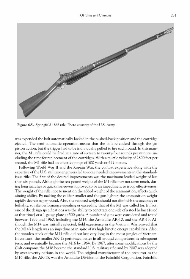
231Of Guns and Cannons
was expended the bolt automatically locked in the pushed-back position and the cartridgeejected. The semi-automatic operation meant that the bolt re-cocked through the gaspiston action, but the trigger had to be individually pulled to fi re each round. In this man-ner, the M1 rifl e could be fi red at a rate of sixteen to twenty-four rounds per minute, in-cluding the time for replacement of the cartridges. With a muzzle velocity of 2800 feet persecond, the M1 rifl e had an effective range of 500 yards or 457 meters.
Following World War II and the Korean War, the combat experience along with theexpertise of the U.S. military engineers led to some needed improvements in the standard-issue rifl e. The fi rst of the desired improvements was the maximum loaded weight of lessthan six pounds. Although the ten-pound weight of the M1 rifl e may not seem much, dur-ing long marches or quick maneuvers it proved to be an impediment to troop effectiveness.The weight of the rifl e, not to mention the added weight of the ammunition, affects quickaiming ability. By making the caliber smaller and the gun lighter, the ammunition weightrapidly decreases per round. Also, the reduced weight should not diminish the accuracy orlethality, so rifl e performance equaling or exceeding that of the M1 was called for. In fact,one of the design specifi cations was the ability to penetrate one side of a steel helmet (usedat that time) or a 1-gauge plate at 500 yards. A number of guns were considered and testedbetween 1955 and 1960, including the M14, the ArmaLite AR-10, and the AR-15. Al-though the M14 was initially selected, fi eld experience in the Vietnam War proved thatthe M14’s length was an impediment in spite of its high kinetic energy capabilities. Also,the wooden stock of the M14 rifl e did not last very long in the moist jungles of Vietnam.In contrast, the smaller AR-15 performed better in all-around comparisons in subsequenttests, and eventually became the M16 by 1964. By 1967, after some modifi cations by theColt company, the M16 became the standard U.S. military rifl e and by 2007 was adoptedby over seventy nations in the world. The original manufacturer of the precursor to theM16 rifl e, the AR-15, was the ArmaLite Division of the Fairchild Corporation. Fairchild
Figure 6.5. Springfi eld 1866 rifl e. Photo courtesy of the U.S. Army.

232 Military Technologies of the World
was and still is a prime U.S. contractor for aerospace products and systems, and one of thereasons for establishing ArmaLite was to use aerospace material for modern weapons.However, Fairchild became disinterested in rifl e manufacturing, in part due to the longand arduous process to replace the larger-caliber M14 as the main rifl e of the U.S. infantry,and sold the right to manufacture the M16 to Colt for a mere $75,000. This transition wasarranged by the Cooper-Macdonald fi rm in Baltimore, who received a substantial amountthrough royalties from Colt for each M16 procured.
The trend of smaller-caliber weapons becoming more lethal and accurate continued onto the M16 (shown in Fig. 6.6), which in spite of the light weight (8.5 pounds) and smaller
Figure 6.6. The M16 rifl e (top) and the M4 carbine, two of the main U.S. military assaultweapons. Photos courtesy of the U.S. Army.

233Of Guns and Cannons
caliber (.223 inch or 5.56 mm) has a muzzle velocity of 3200 feet per second. The smallercaliber meant that the soldier could carry much more ammunition. For example, 22.4pounds of rifl e plus ammunition weight is equivalent to 220 rounds for the M14, but 650rounds for the M16. Early M16 models were even lighter at 6.5 pounds. The M16 is inprinciple fully automatic, meaning that the rounds can be fi red in continuous bursts at upto 900 rounds per minute. This type of fully automatic rifl e is now referred to as an “assaultrifl e.” However, full automatic operation using the M16 is deemed ineffective by the U.S.military because the aim is thrown off by such continuous operation. Also, neither thelight barrel of the M16 nor the thirty-round magazine is suitable for sustained fi ring. Forthese reasons, the current U.S. standard-issue M16 rifl e only has the option of fi ring therounds one by one in semi-automatic mode or in three-round bursts. The U.S. militarydoctrine requires heavier machine guns to be used for sustained suppressive fi re, while in-dividual weapons like the M16 are to be used for aimed, pointed fi re. Many variants exist,with the M16A4 being used by the U.S. Army and Marine Corps up to 1994 with laser,tactical lights, and night vision capabilities. The current standard-issue M4 carbine is amodifi cation of the M16, both of which are shown in Fig. 6.6. The M4 is seen with a Vital2 night vision system attached. Vital 2 is one of the tactical devices that can be attachedto the M4 and includes the aiming infrared laser and illumination beam along with thevision system. It is used for target marking, illumination, and aiming. The use of the infra-red beams makes them visible only through the Vital 2 vision or other infrared viewingsystems. The device can be mounted as shown in the photo with the elevation and azi-muthal fi ne adjustments for aiming through the device.
Although the M16 is one of the most successful rifl es in its caliber class to date at 8 mil-lion rifl es produced worldwide, its beginnings were not as smooth as in most new weaponsincorporating advanced technology. First, the new .223-caliber ammunition had inconsis-tent specs until Remington redesigned its manufacturing process to conform to the re-quired bullet design. The gun had a tendency to accidentally fi re or “slamfi re” when thebolt release was pressed. The sensitivity of the primer in the cartridge and the weight andinertia of the fi ring pin were attributed to this problem. Because the Colt company feltthat the fi ring pin redesign would be a major impediment to bringing the rifl e to full pro-duction status, alternate, less sensitive primer was sought in spite of the risk it posed in ahigher frequency of misfi res. Initially, the main propellant used in the cartridges was IMR-4475 made by du Pont. IMR-4475 had been successfully used for years in .30-caliber andin 7.62-caliber NATO cartridges where the ballistic requirements are less stringent thanin the smaller-caliber M16. IMR-4475, sometimes called “stick powder,” had a tubulargrain of nitrocellulose base with dinitrotoluene (DNT) as deterrent coating that con-trolled the burning rate. However, the U.S. Army set out specs for the new cartridgeswhere they needed to develop muzzle velocity of 3250 +/− 40 ft/s, without exceeding thechamber pressure of 52,000 psi. Initially, few propellant manufacturers could meet suchspecifi cations under short notice, and a propellant called WC846 Olin Mathieson wasthe sole source for some time to produce the M16 ammunitions. WC846 was a double-base(nitrocellulose and nitroglycerine combination) propellant with a deterrent coating ofdibutylphthlate. It has spherical grain, for that reason sometimes called “ball powder.”During its use in the Vietnam War, frequent jamming of the rifl e where the spent car-tridges failed to eject was reported. However, the primary cause was found to be lack oftraining and material for rifl e maintenance. Due to the smaller caliber, the existing clean-ing equipment could not be used on M16s, and residues and moisture tended to accumu-late more easily.
The current ammunition used in the M16 are either 5.56 × 45-mm M193 or M855fragmentation rounds. At a range of 100 meters, these rounds will penetrate four inchesinto body tissues, and any lateral force causes the bullet to break in half with the rear half

234 Military Technologies of the World
fragmenting into multiple pieces. In addition to the bulletrotation, which will cause frictional damage against tissue,the fragmentation effect is quite horrendous, resulting in sub-stantial wounds on passage and exit. Beyond 190 meters, thekinetic energy is reduced, leading to zero fragmentation.
The M16 uses the gas pressure for automatic operation, butin place of gas piston it uses the direct impingement. A port inthe front part of the barrel sends the high-pressure gas backinto the chamber through a gas tube above the barrel, causingthe bolt carrier to be pushed back. This keeps all the recipro-cating mass in the same axis as the barrel and minimizes themuzzle rise during recoil. Although the use of direct gas pres-sure to drive the moving parts simplifi es the design and opera-tion, it does lead to residue accumulation in the fi ring chamber.Vaporized combustion products from the propellant can con-dense in the fi ring chamber. As noted previously, accumulatedresidue can cause malfunctions unless diligently cleaned andremoved.
An attachment to the M16 or M4 that can be frequently seen is the M203 grenadelauncher. Some grenades are designed to be launched directly from the rifl e muzzle usingeither a blank cartridge or using a passage through the center of the grenade to allow thebullet to fl y through. The gas pressure from the rifl e cartridge then propels the grenademounted at the muzzle. The advantage of such systems is that the grenade charge can bemade larger because the propulsion comes from the rifl e cartridge. However, the M230grenade launcher is a stand-alone device that is attached to the rifl e simply so that thesoldier can switch back and forth from the grenade launch to rifl e operations. A separatetrigger for the launcher detonates the propellant of the grenade that hurls the grenadeforward. After a preset amount of time, the explosive charge of the grenade is set off. TheM203 can launch various 40 × 46-mm grenades, from high-explosive, smoke, and illumi-nating to buckshot direct fi re and others for a range of up to 400 meters. At the muzzle, thegrenade is sent off at a velocity of 250 feet per second (76 meters per second).
MILITARY RIFLES AROUND THE WORLD
Other major assault rifl es include the Russian 7.62-mm Kalashnikov, better known asAK-47, shown in Fig. 6.8. The name originates from the designer of this rifl e, Mikhail Ka-lashnikov. Kalashnikov is said to have envisioned the AK-47’s design after being woundedduring a battle against Germans at Bryansk. Two of the sorely needed features were reliabil-ity under muddy and harsh conditions of the battlefi eld and capability for automatic fi ring.These factors led to the simplicity and therefore durability of the AK-47, and in one testwhere the prototype was dragged in mud, sand, and dust the rifl e still fi red without jamming.The large piston, clearance between moving parts, and tapered cartridge design contributeto AK-47 reliability even in the presence of foreign matter in the fi ring chamber. However,the relatively loose tolerance does lead to lack of accuracy at long ranges (beyond 300 to400 meters, which are considered the effective range for an AK-47).
If the M16 and its variants have been used by many of the U.S. allies, the AK-47 hasbeen more than its equivalent for the former Soviet Union and its satellite states as wellas many other nations. One claim has 35 million of these rifl es and variants in existence.The barrel has a 16.34-in (415 mm) length with four grooves, and the magazine has a
Figure 6.7. The M4 carbine with M203grenade launcher. Photo courtesy of theU.S. Department of Defense.

235Of Guns and Cannons
thirty-shot capacity. Its maximum rate of fi re is 600 rounds per minute witha muzzle velocity of 2350 ft/s; 7.62 × 39 mm cartridges with 18.21 grams ofmass are used that give a muzzle kinetic energy of 1467 ft-lb or 2100 joules.The projectile mass is nominally eight grams. Similar to other automaticrifl es, the AK-47 is gas-operated with an actual piston rod permanently at-tached to the bolt carrier. The AK-47’s effi ciency is proven by its sheernumber and ubiquity; however, the rifl e’s accuracy beyond 300 meters issuspect, and there is no hold-open device on the bolt to indicate an emptymagazine, at least in the classical version.
The French military uses FAMAS (“Fusil d’Assault de Manufactured’Armes de St-Etienne,” meaning Assault Rifl e by St Etienne Arms Factory)as the standard assault weapon (shown in Fig. 6.9). FAMAS uses the NATOstandard .223-caliber (5.56 mm) rounds at up to 1100 rounds per minute,with an effective range of 450 meters. Both the M16 and AK-47 have theconventional design of the magazine being placed in front of the handgrip.However, FAMAS reverses this order by placing the handgrip ahead of themagazine. FAMAS is also unique in that the automatic operation isachieved via a blowback mechanism (or lever-delayed blowback tobe exact). The blowback effect occurs due to the cartridge propel-lant gas expanding in the breech that sends the bullet forward andthe bolt rearward. The lever delay is used to control the timing ofthe blowback action because the typical rifl e cartridge generates ex-cessive blowback force. A heavier bolt body is attached to the lighterbolt head against a lever or spring to absorb the initial blowbackforce and release it during forward movement of the bolt head. InFAMAS rifl es, the two-part bolt consists of the light forward part(bolt) and the heavier rear part (bolt carrier), along with a leverpivoted on the forward bolt. During the backward movement of thebolt following the cartridge ignition, the action of the lever is tomagnify the forward bolt movement and transfer it to the bolt car-rier. Because the heavier bolt has large inertia and magnifi ed move-ment, it absorbs the force of the blowback. When the pressure inthe fi ring chamber has decreased, the lever disengages, and the re-turn spring now forces both the bolt carrier and the bolt into thenext fi ring position. FAMAS can be fi red in single-shot or auto-matic fi re with the latter being divided into three-round bursts orfull automatic fi re. The sighting system uses a blade at the front and a dioptric rear sight thatcan be adjusted for range and low-light vision. The FAMAS has a barrel of 488 mm in lengthand a fl ash suppressor that duals as the grenade launcher directly from the muzzle. The rifl ingis three grooves with one complete turn in 228 mm, in contrast to the four to six groovesfound in most other assault rifl es, with no apparent loss in accuracy.
The German G36 is another in the series of high-quality rifl es designed by the Hecklerand Koch. These rifl es only weigh eight pounds with one of the versions G36C at sixpounds, but have long effective range up to 800 meters. The light weight is attributable tothe use of corrosion-resistant synthetic materials (carbon fi ber–reinforced polyamide) formajor components like the receiver housing, the stock, the trigger group, the hand guard,and the carry handle, with steel inserts at other places. Also, the 1990 design is relativelynew and adopts many of the best features of assault rifl es. The components are assembledusing cross-pins so that assembly and disassembly can be done without any tools. The G36uses conventional gas-piston operation in place of the preceding roller-delayed system
Figure 6.8. The AK-47assault rifl e. Photo cour-tesy of the U.S. Army.
Figure 6.9. The FAMAS F-1 assaultrifl e used by the French military.Photo courtesy of the U.S. Depart-ment of Defense.

236 Military Technologies of the World
used in G3 rifl es. The standard sighting equipment includes one 3.5-magnifi cation tele-scope for long-range aims and one laser sighting device for close range.
SNIPER RIFLES
In theory, any rifl e can be used for sniper fi re if the shooter is hidden and is highlyskilled. However, historically some sniper personalities have become legendary. Practicallysniper fi re is used both in military and police forces typically with a specialized selection ofweapons. The fi rst English use of the word “sniper” is attributed to a British soldier’s letterfrom India in 1773. Some etymologists also relate the word to the “snipe,” a speedy bird inthe Gallinago genus that is easily startled and takes off in a spiraling path. But such assaultsfrom far, hidden positions must have been used throughout history. Systematic use ofsniper fi re was used with demoralizing effects by both the British and German sides duringthe stalemates of the World War I trench wars. The British offi cers realized that skilledrifl emen operating singly, in pairs, or in small groups could wield an effect disproportion-ately larger than their actual numbers. Germans also commandeered several thousandsporting rifl es with telescope sights and put them in the hands of men with hunting expe-rience back in the homeland. The results were sparse but psychologically effective shots tosoldiers carelessly exposing themselves above the trench levels. These snipers were givenspecialized ammunition, SmK for longer range and accuracy; a 7.92-mm Gewehr 1898 rifl emodifi ed for sniper use; and the best telescopic sight in the world at the time as providedby the German optics industry. In fact, Germans laid down a systematic doctrine for sniperwarfare that was followed by others into World War II and beyond. The doctrine allowedfor the marksman to operate freely as a “Lone Wolf” or in two-man sniper/observer teams.Countertactics to defeat the snipers were also invented on both sides, one of the simpleones being the use of dummy heads to draw fi re and thereby expose the sniper location.
An example of superior marksmanship overcoming overwhelming odds can be found inthe military annals. In 1939, the Russian Red Army sent 1.5 million troops to annex a partof Finland and came back with half a million. Finland has had a long history of superiormarksmanship because their livelihood at times depended on hunting game, and some ofthe best hunting rifl es still come from this country. Using basic rifl es such as Mosin-Nagantmodels with “iron” sights, some of the Finnish hunter-soldiers could pick off several hun-dred Red Army soldiers marching in columns in narrow ravines or other convergent ter-rains for effective sniper fi re. Most of the Vietnam War was fought against irregular forcesusing unconventional tactics and methods, and sniper shots were one of the ways to wagea war against the U.S. forces superior in armaments and conventional warfare. The U.S.forces countered with sniper squadrons of their own consisting of marksmen from the Ma-
rine Corps. The sniper experience during the Vietnam Warhelped establish the U.S. version of sniper tactics and train-ing. The weapon of choice for the Marine Corps snipersduring the Vietnam War was the M40 or one of its variantsfi tted with 10x Unerti telescope. The rifl e is bolt-actionwith a fi ve-round magazine, though neither the rate of fi renor the number of shots are requirements for sniper weap-ons. Instead, it has a 610 mm barrel that develops 2550 ft/smuzzle velocity to give 7.62 × 51 mm rounds an effectiverange of 1100 yards (1000 meters). Modifi ed versions of theM40 sniper rifl es were used up to the Iraq Wars by MarineCorps sharpshooters.
Figure 6.10. The M40 sniper rifl e camou-fl aged for use in Iraq. Photo courtesy of theU.S. Department of Defense.

237Of Guns and Cannons
Most military forces recognize the need and effectiveness of sniper warfare, and in factin modern times these forward-positioned, sharp-eyed marksmen serve the dual functionsof forward observer and sniper. The Accuracy International Super Magnum from theUnited Kingdom is one of the preferred rifl es for sniper use, with an effective range of 1100meters using .338 Lapua (8.60 × 70 mm) rounds. Again, the rifl e is bolt-action and has atenty-seven-inch barrel. The Super Magnum design originates from the Artic Warfarerifl e. One of the German precision rifl es used by snipers is the Heckler and Koch PSG-1,which is semi-automatic through a roller-locked blowback mechanism. This gun is claimedto be one of the most accurate semi-automatic rifl es in the world with accuracy standardsthat require all PSG-1 rifl es to be capable of centering fi fty rounds in a circle of 80 mm indiameter at 300 meters. However, some of the undesirable features are that the spent can-isters are ejected several meters, exposing the gunner location, and the scope fi xture is notfl exible (it only accepts the Hendsoldt 6 × 42 scope). The accuracy of this rifl e does notcome cheap at close to a US$9000 cost. The Swiss Sig Sauer SG 550 Sniper Rifl e is acompact weapon with a length of 905 mm with the stock folded and fi res a 5.56 × 45 mm(.223 caliber) rounds. The experience in Finland caused the Russians to take sniper war-fare and weapons seriously, and a number of sniper rifl es exist in the Russian arsenal in-cluding the Dragunov SVD semi-automatic sniper rifl e. The SVD is rated at a two minuteof arc accuracy or below. The minute of arc (MOA) is a typical measure of accuracy inrifl es, with 1 MOA typically converting to a variance (shot spread) of about eight inchesat 800 meters. This means that a rifl e with a MOA rating of 1 will center its shots withina circle of eight inches at 800 meters. Military assault rifl es typically have MOA of 3 to 6,while military sniper rifl es have 0.5 to 2 MOA.
Figure 6.11. The Iver Johnson Model 500 .50-caliber sniper rifl e. Photo courtesy of the U.S. Department ofDefense.

238 Military Technologies of the World
Among sniper weapons, the .50-caliber BarrettM82 rifl e shown in Fig. 6.12 is in a different classwith its 1800 meter effective range and the use ofhigh-caliber rounds. The maximum range is 6500meters. When the .50 BMG (12.7 × 99 mm) roundsare fi red at a muzzle velocity of 854 m/s (2818 ft/s),they give a short recoil used for semi-automatic rifl eoperation. The recoil is allowed to move the barreland locked bolt approximately 25 mm rearward. Atthat point, the barrel is stopped and the bolt un-locked from the barrel. The bolt moves yet furtherdriven by the recoil force, ejecting the spent cartridgecase during this movement. During the return move-ment, the bolt clips a fresh cartridge from the maga-
zine and allows it to be placed in the fi ring chamber. Also during this motion, the strikeris re-cocked for the next fi re. The detachable magazine holds ten rounds of ammunition.The .50 BMG rounds were originally developed for the Browning M2 heavy machineguns. Use of other API (armor piercing incendiary) and Raufoss M213 ammunitions cou-pled with the large kinetic energy generated from this rifl e allows targeting of radar instal-lations, vehicles, helicopters, parked aircrafts, and so forth. The Barrett company specializesin large-caliber, high-accuracy rifl es, with the M82 rated at 2.0 MOA or better. The M82and its variants are used as the military SASR, or “Special Applications Scoped Rifl e,” andalthough the typical sales volume is in the hundreds due to its specialized utility this rifl ehas carved a place in various armies (Belgium, Denmark, Finland, France, Greece, Italy,United States, and many others) in spite of its relatively short history.
MACHINE GUNS
Due to their impact on warfare and history itself, machine guns deserve a close look. Wejust saw how recoil or gas pressure can be used to automatically fi re the guns. One of thefi rst successful “machine guns” was the Gatling gun, with multiple barrels connected toseparate loading breeches. The barrels were rotated to fi re their shots in turn, with manuallevers to cause the rotation. This type of high-fi re-rate guns are still used, except of coursethe manual turning has given way to electrical motor drives. However, there were manyattempts to achieve high volume or rate of fi re prior to the Gatling gun. As early 1339,“organ guns” or ribauldequins (also known as rabauld , ribault , or ribaudkin ) exist on record.These were large arrangements of multiple fi ring barrels in parallel layers, to be ignited andtherefore fi red nearly simultaneously. A typical number of barrels ranged from twelve tothirty-six. Although organ guns may have had some shock or concentrated fi re effects,their use in battle was limited due to the inordinate amount of time needed to reload eachof these many barrels. In 1663, a member of the British Royal Society named Palmer actu-ally presented a concept that would not be implemented until about 200 years later. Palmerproposed a concept wherein the gas pressure during the gunpowder explosion was to beused to reload and re-cock the gun for fast repeated action. Both the machining technol-ogy and the type of bullet shells to allow easy ejection would not be available until the1800s to make this concept into reality. Several other notable but less practical inventionsfollowed. The “Puckle” gun can be considered as a precursor to revolvers, where the bulletchambers are rotated by hand to align with the barrel and fi ring mechanism. James Puck-le’s patent in 1718 contains more rhetorical fervor than technical rigor. He proposes to use
Figure 6.12. Barrett M82 .50-caliber sniper rifl e.Photo courtesy of the U.S. Marine Corps.

239Of Guns and Cannons
chambers containing round bullets for use against Christians and square bullets for theTurks. A design by a Danish inventor named N.J. Lobnitz was actually built and deliveredreasonable performance: a fi ring rate of up to eighty shots per minute and enough muzzlevelocity to punch through a one-inch pine board at a range of 250 feet. However, its undo-ing was the gigantic air pump with two six-foot-diameter fl ywheels to drive the gun. An-other unwieldy design proposed in 1854 by Sir Henry Bessemer was to use steam to drivethe feeding, locking, and fi ring mechanisms.
The Gatling gun, patented in 1861 by Richard Jordan Gatling, can be considered as thefi rst successful machine gun adopted by the military for wide use. The encased cartridgedesign allowed for mechanical loading, and the manual crank was used for sequential fi ringof the cartridges. The complex multi-barrel design and the manual crank were replaced byHiram Maxim in 1881 in his “Maxim gun” that used the recoil force to reload as in mod-ern automatic pistols. In fact, all automatic fi rearms may be considered a precursor tomachine guns, except that the conventional concept of machine guns applies to high rateof fi re, on the order of several hundred rounds per minute, and a large-capacity magazine.In fact, some automatic rifl es can be modifi ed to operate like a machine gun. To preventoverheating from a sustained high volume of fi re using a single barrel, the barrel was placedin a water cooling jacket. Also, linked cartridges (ammunition belts) were used to facili-tate automatic loading. This innovation during World War I brought horrendous casual-ties on both sides who insisted on medieval tactics of charging against entrenchmentsguarded by machine guns.
As noted above, the automated reload and fi ring methods used in pistols and rifl es arealso used in machine guns. Recoil force is used for smaller fi rearms and gas-operated sys-tems for large caliber weapons. The Colt-Browning M1895 is credited with being the fi rstgas-operated machine gun. The multiple barrels of the Gatling type of guns, for their largevolume and rate of fi re, are again found in mini-guns or chain guns (see Chapter 3), exceptelectric motors are used to operate the guns. The force from the recoil, the gas motor, orthe electric motor is used to run the machine gun fi ring cycle, which involves ejecting thespent cartridge through the breech port, cocking the trigger mechanism and releasing it,and loading the next cartridge into the fi ring chamber.
Automatic rifl es, like the M16 or AK-47, may be considered miniature machine gunsbecause their theoretical rate of fi re is several hundred rounds per minute. Of course, theconventional light barrel and magazine on these assault rifl es preclude such uses. Atthe other extreme on the machine gun scale, hydraulically operated “chain guns” like theGAU-8/A fi re 30 mm rounds, in comparison to the rifl e caliber of 5.56 mm or the squadmachine gun (e.g., M240) caliber of 7.62 mm. Thus, rapid-fi re machine guns are availablefor various purposes, from infantry suppressive fi re to anti-aircraft and anti-missile fi re.
The Austrian Steyr AUG/HBAR is a rifl e fi tted with a heavy barrel and bipod andserves as a light machine gun. As with the rifl e, it uses the NATO standard 5.56 × 45 mmrounds. The feed system is a forty-two-shot detachable box, and the muzzle velocity is3280 ft/s. The Belgian machines guns are marketed under the FN (Fabrique Nationale)brand, but FN itself is a part of the famed Herstal group that also includes Browning andWinchester and supplies a large chunk of the world’s small fi rearms including machineguns. FN MAG uses the 7.62 mm caliber rounds and is widely adopted as the suppressivefi re weapon that uses this ammunition. MAG is an acronym for Mitrailleuse d’Appui Gen-eral , meaning general purpose machine gun, and the M240 (Fig. 6.13) is simply the U.S.version of the same gun. The weapon operation involves pulling the charging handlerearward, opening the feed cover, and engaging the rounds. Once the feed cover is closedand the safe lock disengaged, the weapon is ready for fi re. There are three settings for therate of fi re—750, 850, and 950 rounds per minute—that can be fi ne-tuned by adjusting the

240 Military Technologies of the World
gas regulator. To prevent barrel overheating, the mili-tary specifi cation is to change the barrel after empty-ing two 220-round belts. The barrel replacement ismade quite simple and fast, with a barrel release but-ton located on the left side. After clearing the fi ringchamber, the release button is pressed while the car-rying handle is rotated away. By pushing down andforward on the barrel, it is removed and the replace-ment barrel can be placed in seconds. However, theMAG has proven to be an extremely reliable weaponwith up to 26,000 rounds being fi red before failure in
tests. In several instances, up to 8000 rounds were fi red without an opportunity to replacethe barrels, and MAG fi red effectively even with the barrel glowing red from overheating.The other FN machine guns fi re different caliber rounds such as the Minimi 5.56 mm,BRG51 15.5 mm, and M2HB/QCB 12.7 mm (.50 inch).
The updated FN M3M is rapidly becoming the standard heavy machine gun with en-hanced capabilities. The M3M is designed to replace the .50-caliber M2 machine guns,with improvements in rate of fi re, safety, accuracy, lethality, and reliability. The M3Mcomes with system components, including the machine gun itself, the soft mount, and thecradle to integrate the gun to the vehicle platform so that no vehicular modifi cations areneeded. The M3M fi res from an open breech so that the risk of live rounds getting over-heated and exploding in the breech (cook-off) is all but eliminated. The soft mount actsas a shock absorber for the recoil and counter-recoil forces. M3M has a weight of eightypounds, sustained rate of fi re of 200 rpm, maximum rate of fi re of 1100 rpm, barrel life ofup to 10,000 rounds, and ammunition capacity of 300 rounds per box. The M3M system isalso equipped with a laser illuminator and spotter.
The MAC series machine guns by the French Chatellerault have been around sinceWorld War I. MAC stands for Manufacture d’Armes de Chatellerault or Chatellerault armsmanufacturing. The MAC-10 is a blowback-operated, compact submachine gun that iswidely used due to its low cost and high rate of fi re in spite of its compact size. In contrast,the AAT-52 is the French military general purpose machine gun using 7.62 mm NATOstandard rounds. The AAT-52 operates on a delayed blowback mechanism similar to theFrench assault rifl e, FAMAS, that produces a 700 rpm rate of fi re.
Most of the world’s major military powers design and produce their own versions ofmachine guns, and it is not the intent of this book to catalog them. However, to give anindication of the variety and number of different automatic weapons produced, we canlook at the Russian weapons. The assault rifl es, which again may be considered as a lightmachine gun, typically start with the letter “A” as in AK-47, AK-74, AK-97, AB-762, andmany others in the Russian assault rifl e arsenal. There are about half a dozen Degtyarevlight machine guns using 7.62 mm rounds, such as the DP-27, DPM, DA, and RP-46. TheDshK series of heavy machine guns use 12.7 mm ammunition. Other heavy machine gunsinclude the Kord, KPV, and tank-mounted KPVT using 14.5 mm rounds. The NSV heavymachine guns also use 12.7 × 108 mm rounds. The NSV stands for three of its designers,G.I. Nikitin, Y.S. Sokolov, and V.I. Volkov, and was intended to replace the DShK ma-chine guns. However, the Kord heavy machine guns replaced NSV for tank-mounted oranti-aircraft fi ring capabilities. The Kord machine guns have a length of either sixty-fourinches (tank-mounted) or seventy-eight inches (aircraft) and with a dispersion (spread) of0.22 m in the initial 100 m have an effective range of 1500 to 2000 meters. The PK seriesgeneral purpose machine gun, originally evolved from the Kalashnikov automatic rifl edesign, is currently used in the modernized PKM version, using the 7.62 × 54 mm rounds.
Figure 6.13. The M240 general purpose machinegun. Photo courtesy of the U.S. Army.

241Of Guns and Cannons
In contrast to the NATO counterparts such as FN MAG,M240, MG3, or M60, PKM machine guns load from the rightside and eject to the left side.
The U.S. military also carries a wide range of machine gunsfor specifi c functions. As noted above, the FN MAG is used asthe general purpose machine gun, designated M240. The M60machine gun is the classic machine gun, replaced by the M240.Alongside the M240, the light squad machine gun M249 (FNMINIMI), shown in Fig. 6.14, and heavy machine gun M2 orM3M are also used.
A much higher rate of fi re is generated in externally pow-ered guns based on the Gatling design of rotating barrels. Forexample, the XM214 microguns and M134 miniguns use 5.56and 7.76 mm NATO rounds respectively, similar to the M249 and M240. However, therate of fi re is, as one may expect, about six times higher due to the same number of barrels.The electrically rotated barrels produce 4000 to 10,000 rpm (rounds per minute) in theseGatling-type guns. Due to the electrical power and ammunition volume requirements,these guns are not intended for infantry use but rather on vehicular platforms such as at-tack or attack support helicopters. The six barrels are normally aligned in parallel, buttheir angle of convergence can be adjusted to control the dispersion rate. The “actionbody” that contains six bolts is located behind each barrel, as the ammunition is fed to thetopmost barrel the bolt thrusts forward to fi re that round, and this sequence is rotated againusing an electrical drive. The M134 minigun manufactured by General Electric originatesfrom the much larger 20 mm Gatling-type Vulcan cannons (shown in Fig. 6.15), andsimilarly the Hughes Chain Gun fi ring 25 and 30 mm rounds was modifi ed to fi re 7.62 mmrifl e rounds. The Chain Gun, unlike the minigun or microgun, is not of the multiple-barrelGatling type. The Chain Gun has a single barrel but the automatic fi re is externally pow-ered and controlled rather than using internal forces such as recoil or gas pressure. Thename, “Chain Gun,” originates from the internal roller chain that drives the bolt mecha-nism. The ammunition feed is also mechanically driven in synchronization with the boltmechanism, so that the ability to handle large ammunition volume is enhanced.
The large-caliber chain guns (M230) using 30 mm rounds are used on Apache attack heli-copters. The externally powered guns of this caliber range are usually used on aircraft or anti-aircraft batteries. The principal cannon on U.S. fi ghter aircraft for over thirty years has beenthe M61 Vulcan (see Fig. 6.15) using 20 mm ammunition. The F-14, F15, F16, F/A-18, F-111,F-104, and F-22 aircraft all carry the General Electric M61 with varying amounts of ammuni-tion volume. The M61 is also the basis for the naval close-in weapons system such as the U.S.Phalanx. The Vulcan is a Gatling-type of rapid-fi re (approximately 100 rounds per second)cannon with six hydraulically driven barrels. The hydraulic drive rotates the six barrels, whichfi res in turn, and the electrical current is sent through the fi ring pin to the primer for precisetiming of the cannon fi re. The rate of fi re is 6000 rounds per minute, with typically less than1000 rounds carried by each aircraft. The calculated use of the rounds is a given constraint ofthese weapons. However, Vulcans do take 0.3 to 0.5 seconds to “spin up” to achieve full speed,and a practical rate of fi re is approximately 2000 rounds per minute. A more potent version isthe fi ve-barrel GAU-12/U “Equalizer” that fi res 25 mm ammunition. A variety of rounds canbe fi red at this caliber, including high-explosive incendiary (HEI), HEI with tracer (HEI-T),armor-piercing incendiary (API), and armor-piercing discarding sabot (APDS). The APDSrounds have been known to penetrate moderate tank armors. The 30 mm Gatling guns GAU-8/A “Avenger” and GAU-13/A have seven and four barrels respectively and are used in attackaircraft like the A-10 Thunderbolts.
Figure 6.14. The M249 light machinegun. Photo courtesy of the U.S. Army.
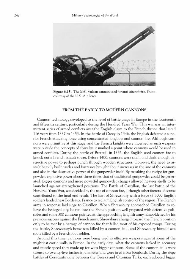
242 Military Technologies of the World
FROM THE EARLY TO MODERN CANNONS
Cannon technology developed to the level of battle usage in Europe in the fourteenthand fi fteenth century, particularly during the Hundred Years War. This war was an inter-mittent series of armed confl icts over the English claim to the French throne that lasted116 years from 1337 to 1453. In the battle of Crecy in 1346, the English defeated a supe-rior French attacking force using concentrated longbow and cannon fi re. Although can-nons were primitive at this stage, and the French knights were incensed as such weaponswere outside the concepts of chivalry, it marked a point where cannons would be used inarmed confl icts. During the battle of Breteuil in 1356, the English used cannon fi re toknock out a French assault tower. Before 1400, cannons were small and dealt enough de-structive power to perhaps punch through wooden structures. However, the need to as-sault heavily built castles and fortresses brought about increases in the size of the cannonsand also in the destructive power of the gunpowder itself. By tweaking the recipe for gun-powder, explosive power about three times that of traditional gunpowder could be gener-ated. Bigger cannons and more powerful gunpowder charges allowed heavier shells to belaunched against strengthened positions. The Battle of Castillon, the last battle of theHundred Years War, was decided by the use of cannon fi re, although other factors of coursecontributed to the fi nal end result. The Earl of Shrewsbury with a force of 3000 Englishsoldiers landed near Bordeaux, France to reclaim English control of the region. The Frencharmy in response laid siege to Castillon. When Shrewsbury approached Castillon to re-lieve the besieged city, he ran into the French position well prepared with defensive pali-sades and some 300 cannons pointed at the approaching English army. Emboldened by hisprevious success against the French army, Shrewsbury charged toward the French positiononly to be met by a barrage of cannon fi re that felled most of his exposed troops. Duringthe battle, Shrewsbury’s horse was killed by a cannon ball, and Shrewsbury himself wassoon killed by a French foot soldier.
Around this time, cannons were being used as effective weapons against some of themightiest castle walls in Europe. In the early days, what the cannons lacked in accuracyand muzzle speed they made up for with bigger cannons. Some of the cannon balls weretwenty to twenty-fi ve inches in diameter and were fi red from bombards. During the siegebattles of Constantinople between the Greeks and Ottoman Turks, each adopted bigger
Figure 6.15. The M61 Vulcan cannon used for anti-aircraft fi re. Photocourtesy of the U.S. Air Force.

243Of Guns and Cannons
and better guns for defense and siege of the walled city. By 1422, the Turks were using shortbut large-caliber cannons called “falcons” basically to hurl large cannon balls in the gen-eral direction of the castles. By 1453, they were using Hungarian-built cannons, and for aperiod of ninety days kept on bombarding the heavily fortifi ed walls. One of the guns,called the Dardanelles gun, was particularly fearsome requiring 60 oxen and 400 men toplace it in fi ring position. Once placed in position, the Dardanelles gun required sevendays of preparation prior to the fi rst fi re. The gun was 5.18 meters (17 ft) long and had acaliber of 763 mm (30 in). The gun sent granite stones of 680 kg (1500 lbs) and 30 inchdiameter onto and over the city walls, crushing everything and everyone in their path. OnMay 29, 1453, the mighty wall of Constantinople was breached by continuous bombing bythese huge granite stones and fell to the Turks, altering the medieval concept of warfare.Some 300 years later in 1807, the same Dardanelle guns were brought out and fi red againstapproaching British ships. The gun operated fl awlessly, and one of the shots led to 60 ca-sualties on one of the British ships.
Figure 6.16. A nineteenth-century mortar. Photo courtesy of the U.S. Department of Defense.

244 Military Technologies of the World
Up to the 1800s, all cannons were smooth bore, muzzle-loading types constructed fromiron or bronze. Muzzle loading meant that the cannons onboard naval vessels had to be puton four-wheeled truck carriages and moved back and forth from the fi ring porthole. Actu-ally, the cannon recoil pushed back the carriage until it was stopped by breeching ropes.The men, wielding a variety of cleaning and loading tools such as handspike, wormer, ram-mer, sponge, linstock, cat, scraper, and ladle, then swarmed on the cannon to prepare forthe next fi ring. First, the gunpowder was put in the barrel using the ladle with a cylindricalscoop and long handle. The primer was also poured into the vent hole. Then the wad,simply a piece of rag or even straw, was placed between the gunpowder and the ball withthe rammer. The ball had to be exquisitely cleaned prior to fi ring to prevent damage to thebore. The fi ring was done by lighting with a match that was kept at the end of a stick calledthe linstock. The gun crew captain was in charge of the actual fi ring maneuver, as well asaiming of the cannon prior to that. After fi ring, the gun was cleaned out using the sponge,again on a long stick, and wormer, which was an iron double screw used to scrape out bitsof the burnt wad. The barrel now was wetted with the sponge to kill any residual sparksprior to loading the new gunpowder charge.
Some of the improvements in cannons that were to be made in the 1800s included ri-fl ing of the barrel and breech loading. It was known by this time that round cannon ballssuffered from air resistance as well as susceptibility to wobbling, which is also due to aero-dynamic forces. By rifl ing the barrel, oblong projectiles can be fi red while maintainingtheir longitudinal orientation to present a more streamlined shape. An Italian inventionin 1846 called the “Cavelli” shot had four projecting studs on the projectile that were in-tended to follow the two spiral grooves on the barrel. In later years, bronze or copper bandson the shells were used so that they could “catch” the grooves on the barrels. Iron was toohard to deform to follow these grooves. Also, after some vacillating designs, the Britishand Americans settled on breech-loading cannons, particularly after one incident by theBritish navy wherein the gun charges were loaded twice by accident and ended up blowingup the barrel and a good chunk of the naval vessel. The perfection of the interrupted screwbreech block allowed reliable operation of the breech-loading cannons. Modern cannonammunition also took shape during this period where the propellant in a brass case wasattached to the projectile so that the rounds could be loaded as a single unit. Also, up tothis point the cannon mounts were rigid and the force of the recoil would push the entirecannon, truck, and everything else with it. Recoil-absorbing devices like oil-fi lled cylin-ders and cradles appeared by the turn of the nineteenth century. Finally, a combination ofthe barrel cradle and a nitrogen-fi lled cylinder allowed the cannon to be fi red, compressthe nitrogen gas, and on expansion of the gas bring the barrel back to loading position.
During World War I, the advances in cannon technology would be used in a range of gunsfrom 37 mm infantry cannon to the gigantic German “Paris Gun.” The Paris Gun, so namedbecause the Germans used it to bombard Paris from Crepy, was so heavy and long that the bar-rel had to be supported by a secondary suspension truss. Some of the numbers are unheard ofbefore or after this supercannon: The gun weighed 256 tons and so had to be mounted on rails,its rifl ed barrel was 28 meters long and of a 210-mm caliber (that is about seven feet). Theprojectile was 94 kg, reached a speed of 1600 meters per second (about fi ve times the speed ofsound), and the range was 75 miles covered in a 170-second trajectory with a peak altitude of40 km. The pressure developed in the barrel was so high that after sixty-fi ve shells were fi red,the barrel had to be replaced. In spite of these numbers, similar to the V-1 and V-2 rockets ofWorld War II, the main effect of the Paris Gun was psychological because the number of roundsthat could be fi red and the accuracy were limited.
The “Big Bertha” howitzers were another matter. Big Bertha, a translation of the Ger-man Dicke Bertha or “Fat Bertha,” in fact later became synonymous with really big guns

245Of Guns and Cannons
including the Paris Gun and Langer Max. Unlike the Paris Gun, the Big Berthas could fi rea formidable 820 kg rounds to a maximum distance of 12 km, and they could also bemoved on wheels (M-Gerat version) or on rails (Gamma Gerat). Under bombardmentsfrom these big guns a series of Belgian forts—Liege, Namur, Maugeuge, and Antwerp—fellinto German hands. Classical fortifi cations did not last very long against these behemothsuntil reinforced concrete building material was used for added protection. The Japanesealso used 280 mm cannons in the battle to take Port Arthur during the Russo-Japanese War.The German big gun design was even adopted by the United States in the M65 “AtomicCannon.” The M65, now having been decommissioned, was intended to launch atomicand conventional warheads of in a 550-pound projectile over a range of twenty miles. The47-ton gun was based on the design of the 280 mm caliber German K5 Railroad Gun andwas transportable on tractors.
MODERN MORTARS AND FIELD ARTILLERY
Mortars are simplifi ed devices where muzzle-loaded rounds are drop-fi red for short rangesupport fi res. The weight of the round causes suffi cient impact with the fi ring pin, whichsets off the propellant charge in the mortar round. The resulting blast propels the roundback out of the smoothbore barrel toward the intended trajectory. Thus, mortars can onlybe fi red at an angle to follow a free fall under gravity toward the target. The light mortarslike the M224 60 mm allow disassembly and transport by infantrymen and thus are suit-able for direct infantry fi re support. Mortars have simple sight and range indicators includ-ing nighttime vision capabilities. To add range variations to the rounds, the mortar roundshave detachable incremental propellant cartridges that can be broken off to get the rightrange. The propellant charge and the inclination angle would then determine the rangeand duration of the fi red rounds. Different explosive charges are available for infantry use,such as the M720 High Explosive, M721 Illumination, M722 Smoke, and M723 WhitePhosphorous. The fuse can also be set for PRX (Proximity Burst), NSB (Near SurfaceBurst), IMP (Impact Burst), or DLY (time delay), with DLY being used for a number ofdifferent effects including ground penetration. The hand-carried version weighs only 18.0pounds, although the conventional version of the same mortar gives a much larger rangeat a weight of 46.5 pounds. The barrel length of 38 inches is approximately seventeentimes the caliber (60 mm). From the mortar mount, the elevation change of 45 to 85 de-grees sets the range from 76yards to 3817 yards for the conventional M224 and to 984yards for the hand-carried version. Also, a traverse of 7 degrees to each side can be madefor fi ne-tuning of the targeting.
A typical mortar round is shown in Fig. 6.17. Again, the construction is simplifi ed witha “wraparound” propellant charge that can be removed or added in increments for rangecontrol. The fi ns at the tail stabilize the mortar fl ight because the barrel is not rifl ed andno rotation is imparted on the rounds. The ignition cartridge with primer is located intothe base of the fi n shaft. When the mortar round is dropped into the barrel bottom, thefl oating fi ring pin assembly in the ignition cartridge strikes the primer. The primer fl ash(hot combustion gas) travels along a thin tube in the mortar body into the main ignitioncartridge. The ignition cartridge then explodes, sending fl ash into the main propellants.The main propellant detonation produces a high-pressure, high-temperature conditionthat propels the round out of the barrel, while the obturating ring provides a fi t betweenthe round and the barrel so that the combustion gas is kept within the barrel until themortar round clears the muzzle. As noted above, several different fuse types are availablealong with the explosive cargo in the shell body. The DLY fuse has time delay of some up

246 Military Technologies of the World
to fi fty seconds and is adjusted by turning thegraduated fuse cone. To avoid accidents, a safetywire must be removed to activate the fuse be-fore fi ring. On IMP fuses, there is also a safetywire along with delayed arming feature to main-tain the unarmed, detonation-safe status for aminimum of 1.25 seconds of fl ight, again to elim-inate the possibility of the IMP fuse being setoff during launch or close to the launch pad. Amultifunctional fuse, the M734 MO, allows anumber of different settings including PRX forexplosion three to thirteen feet above the ground,NSB at three feet above the ground, or IMP orDLY of 0.05 seconds.
Larger caliber mortars are also useful, againdue to their compactness. The 81 mm M252and 120 mm M120 can be towed or mounted inarmored vehicles as shown in Fig. 6.18, requir-ing a crew of four to fi ve to operate. Both areimports, with the M252 being the British L16mortar and the M120 Israel’s TT6. A photo-graph of the M120 120 mm mortar gives anidea as to its size, with the round’s caliber actu-ally being larger than some howitzer rounds.The mortars are held fi xed on bipods and a cir-cular base plate. At this caliber, fl ared blastattenuators are used to minimize the shock of
mortar launch, and the barrel also has heat dissipater fi ns. These weapons deliver fi re at arange of 6124 yards for the M252 and 7918 yards for the M120. In addition to the conven-tional rounds, these mortars have the potential to fi re terminal homing rounds foranti-tank capability.
Towed howitzers are classic artillery pieces dating back to World War I and earlier eras.Their strength lies in the ability to deliver massive, concentrated fi re from organized fi rebases, at the expense of reduced mobility and protection. The M119 105 mm howitzer
Figure 6.17. A schematic of a mortar round.
Figure 6.18. A vehicle-mounted 120 mm M120 mortar.Photo courtesy of the U.S. Army.

247Of Guns and Cannons
(shown in Fig. 6.19) used by the U.S. Army is a license-built version of the British L118Light Gun. The advantage of this relatively small caliber cannon is its transportability andstable platform. It can be towed by a land vehicle, airlifted by the UH-60 Black Hawk(one) or CH-47 Chinook (two) on slings, or dropped from C-130 Hercules using para-chute or the Low-Altitude Parachute Extraction System (LAPES). The barrel length of 9ft 1 in is rifl ed with thirty-six grooves to give rotational acceleration and a muzzle velocityof 1800 ft/s (549 meters per second). A number of projectiles can be fi red from the M119:M101 standard High Explosive (HE), M913 Rocket-Assisted HE (HERA), M546 Anti-personnel with Tracer (APERS-T), M444 Improved Conventional Munition (ICM), orXM915 Dual Purpose Improved Conventional Munition (DPICM). The M760 propellantcartridge provides blast-off thrust for these projectiles for a range up to 21,325 yards or 19.5km for HERA and less for other heavier rounds.
The M109 Paladin shown in Fig. 6.20 is a widely used 155 mm howitzer mounted in aturret of a tracked vehicle. It can deliver a coordinated barrage using the A6 155 mmM284 rifl ed howitzer with thirty-nine rounds. The fi re coordination is via the Automatic
Figure 6.19. The M119 105 mm howitzer. Photo courtesy of the U.S. Army.
Figure 6.20. The M109 Paladin 155 mm self-propelled howitzer. Photo courtesy of theU.S. Army.

248 Military Technologies of the World
Fire Control System (AFCS), which digitally points each of the guns in the artillery groupand sequences the fi ring order. Although not as well armored as the main battle tanks, theKevlar and rolled homogeneous steel armor provide some level of protection for the fi vecrew inside. The range of 26,247 yards combined with the Paladin’s mobility allows fl uiddeployments of close fi re support in rapid advance or retreat situations over diffi cult ter-rains. A turbocharged V-8 engine, the 8V-71T, made by General Motors powers the drivetrain with a top speed of 35 mph and an operating range of 220 miles without refueling.
BALLISTICS
Ballistics refers to the science of maximizing the effectiveness of projectiles fi red from gunsor artillery. We can consider three different sub-branches of ballistics: external ballistics,internal ballistics, and forensic ballistics. Forensic ballistics deals with the possible trajectoryand type of the projectiles in causing the resultant damage and is somewhat outside the scopeof our discussion. The external ballistics examines the aerodynamic forces of rotating (if fi redfrom a rifl ed weapon) projectile, and although geometry and scale may vary from bullets fi redfrom a small arms to ballistic missiles the fundamental principles of high-speed aerodynamics(sometimes referred to as gas dynamics) are universally applicable. A “Schlieren” image ofthe air fl ow fi eld around an artillery round moving at a supersonic speed is shown in Fig. 6.21.Shock waves project from the nose of the round as the surrounding air gets rapidly com-pressed by the supersonic projectile. All aerodynamic disturbances travel at the speed ofsound, and because the projectile travels faster than the speed of sound the disturbance isnearly instantaneous and causes the shock wave across which the pressure jumps to a highlevel. This shock wave results in the sonic boom that can be felt several miles away andalso causes great discomfort to those nearby. In fact, such shock waves are also generatedwhen the round detonates, except such detonation waves induce a much higher pressureincrease and contribute to the lethal effects at close range along with the major damagesassociated with the bomb fragments. The Schlieren imaging used in the fi gure makes useof the light refraction as a function of the air density (i.e., anywhere there is a densitychange across the shock wave it will show up as dark lines as in the photograph). The in-creased pressure somehow will return to the ambient pressure, and it does so through anumber of expansion waves seen near the tail of the round in the image. Also, the highfl uctuations of density in the wake region (left of the fl at end in the image) can be seen.The spin imparted by the rifl ed barrel on the round ensures that the projectile is stablealong its longitudinal axis, and this will present the minimum cross-sectional area for mo-tion against air as well as a symmetrical shape. Any asymmetry in the profi le and thereforeaerodynamic forces will cause the round to veer from a straight intended line. The projec-tiles are designed for stability and minimum drag, with the front part typically being shapedin the form of an “ogive” for minimum drag at supersonic speeds. An ogive is an arc withthe center located on a line that is perpendicular to the projectile axis. For smaller projec-tiles, a simple conical shape is also used. Also, depending on the application the penetra-tion capability of the projectile may precede other considerations.
The internal ballistics is concerned with how the gun propellant inside the gun cham-ber and the barrel builds up in time to generate the pressure necessary to give the roundstheir initial velocity out the muzzle. Again, regardless of whether the projectile is a small-caliber handgun bullet or a 150 mm artillery shell, the fundamental processes are thesame. The impact of the fi ring pin on the primer sets off the ignition of the primer itself,which then fl ashes to explode the main solid propellant sitting in the gun chamber as apart of the projectile/propellant combination. The explosion produces a large volume of

249Of Guns and Cannons
combustion-product gas in the reaction chamber at a high temperature and builds up thepressure. At the shot start pressure of 2000 to 10,000 psi (depending on the artillery typeand caliber), the projectile motion begins, and the force of the motion starts to engage therifl ed grooves on the rotation band of the projectile body. The pressure continues to buildup to accelerate the projectile, and the rifl ed bore causes the projectile to spin. The maxi-mum pressure is reached soon after the spin is initiated, and as the projectile moves alongthe barrel the pressure decreases somewhat until it clears the muzzle at which point the pres-sure is called the muzzle pressure. For a small-arms gun chamber, the peak pressure is reachedin approximately 2/1000th of second after the fi ring pin impact and drops to about half thepeak pressure by 3/1000th of second. The pressure decreases gradually from that pointuntil the round exits the barrel. The residual pressure is used to drive the fi ring bolt backin automatic rifl es by bypassing that pressure through a separate tube.
Figure 6.21. An image of a speeding artillery round. Photo courtesy of the U.S.Department of Defense.

250 Military Technologies of the World
Since the late 1800s, nitrocellulose-based gunpowder has replaced the black powder asthe main gun propellant. Nitrocellulose by itself was highly unstable and diffi cult to con-trol, so that modifi ers like colloidon (mixture of ether, acetone, or alcohol) were added toimprove stability, safety, and burning characteristics. Three types of gun propellants areused: single-base with nitrocellulose plus additives, double-base with nitrocellulose andnitroglycerin, and triple-base with nitrocellulose, nitroglycerin, and nitroguanidine. Gunpropellant grains may change color during storage, which is not an indication of any deg-radation. However, over a long period of time they may undergo slow but unstable chemi-cal decompositions independent of the grain colors, and under rare instances the gunpropellant can spontaneously ignite. The products of decompositions are acidic and canaccelerate further degradation. Diphenylamine is used as an additive to offset the acidicdecomposition. Also, high temperatures above 90o F and moisture tend to speed the de-composition rate, and therefore storage of gun propellants in cool and dry environment ishighly desirable because any decomposition means loss of heat units in the propellant.Triple-base propellants are most resistant against decomposition due to their low nitrocel-lulose content (less than 1/5th) volatile contents.
The gun propellant itself is usually not ignited by impact but by a fl ash fl ame from theigniter and/or primer. Thus, the impact of the fi ring pin ignites the primer that producessuffi cient heat to set off the igniter material. The fl ame from the igniter is fl ashed to thegun propellant, fi nally resulting in the ignition of the main propellant. For gun bore di-ameters of less than 37 mm, the igniter material (such as barium nitrate, potassium chlo-rate, lead sulfacynate, or other pyrotechnic substances) is located at the base of the roundin a small percussion cap. Thus, the burning of the propellant proceeds from the base tothe front and requires longer time for complete combustion. Larger-caliber rounds areconstructed with a thin inner tube of igniter material and a vented tube so that the com-bustion can proceed radially in the main propellant charge. High burning rate ignitermaterials with good heat release capacity include zirconium/barium chromate, alumi-num/cupric oxide, magnesium sodium nitrate, and potassium nitrate. Once the mainpropellant is ignited, its burning rate is determined by several factors. The propellanttype, the size and shape of the propellant grains, and additives and other extraneous ma-terial content all affect how fast the propellant will burn out and therefore raise the pressurein the gun chamber. For artillery propellant, a number of different grain shapes and sizesare used, from simple ball, cord or strip grains to multi-perforated, all resulting in differentburning rate history.
Figure 6.22. Components of an artillery gun.

251Of Guns and Cannons
REFERENCES
Boot, Max. War Made New: Technology, Warfare, and the Course of History, 1550 to Today . New York:Gotham Books, 2006.
Brookesmith, Peter. Sniper, Training, Techniques and Weapons. New York: St. Martin’s Press, 2000. Hogg, Ian V., and John Weeks. Military Small Arms of the 20th Century, A Comprehensive Illustrated
Encyclopedia of the World’s Small Caliber Firearms . Iola, WI: DBI Books, 1991. Krier, Herman, and Martin Summerfi eld (eds.). Interior Ballistics of Guns , Vol. 66 Progress in Astro-
nautics and Aeronautics . Reston, VA: American Institute of Aeronautics and Astronautics, 1979. Tunis, Edwin. Weapons: A Pictorial History . Baltimore, MD: Johns Hopkins University Press, 1954.

This page intentionally left blank

A BRIEF HISTORY OF TANKS
BUILDING A DEFENSIBLE STRONGHOLD must have occurred very early in thehuman history. Having a secure, safe place to guard against incursions is a physical andpsychological necessity in any strife-ridden life. Caves in steep rock cliffs and medievalcastles—walled barricades in strategic locations—are examples of the human desire toconstruct a protective shield. However, protection alone is not effective in battle situa-tions. Castles can be subject to siege and bombardments by the attacking force. In fact, asthe methods to build bigger and stronger castles evolved, so did the technology for siegemachines and strategies to neutralize the strongholds. With strong defensive positions, youmay not lose the battle, but it is not possible to dictate a decisive victory. At some point,a mobile force must engage the enemy and force a showdown.
Mobility in battles is a valuable commodity, and as early as 1100 BCE elaborate chariottechniques were used by Assyrians in the Mesopotamian region (present-day Iraq andSyria). A Briton queen called Boadicea (sometimes spelled Boudica) is known to haverallied her troops against the Romans using, among other weapons, an open chariot in thefi rst century CE . However, chariots were not exactly armored vehicles; in fact, the warriorswere quite exposed, and soon their mobility was offset by such vulnerability to foot soldiersand horse-mounted warriors. A defensive shielding technique called “testudo” was per-fected by the Romans as a method to approach fortifi cations. Testudo, meaning tortoise,was simply a formation of shields put up by foot soldiers underneath to form a seamless roofover their heads against darts, arrows, and other small projectiles. It is recorded, however,that the Roman testudo advances were beaten back by pouring boiling fat onto the shieldsor toppling a heavy object. A knight’s armor, weighing under 100 pounds, can be consid-ered as an effort to combine armor, mobility, and armament, the latter being the weaponwielded by the wearer.
With the development of cannons, however, advantages in combining armament, armor,and mobility began to be realized by some military minds. A mercenary general namedJohn Zizka led a peasant uprising of the Bohemian Hussite sects against imperial forces ina region corresponding to modern Czech Republic. He converted ordinary, four-wheeledfarm carts into cannon-mounted fi ghting vehicles appropriately called “battle-wagons.”Using the mobility afforded by the wheeled carts, he could build formations and movethem to strategic locations for optimum deployment of cannon forces during the battle.
CHAPTER
7
FORTRESS ON WHEELS:MAIN BATTLE TANKS

254 Military Technologies of the World
A second type of battle-wagons was also built for “armored” troop transport. Woodedsides were added to the carts, so that troops of up to eighteen men could be carried underprotection. In battle, the cannon-wielding battle-wagons could be formed into a fortress-like formation, with space between the carts covered with wooden boards. These deviceswere highly effective against conventional weapons of the time, and the Hussite armyremained victorious over fourteen years of warfare during the early 1400s CE . In 1838, anEnglish gentleman named John George of Saint Blazey, Cornwall, recorded a petition tothe House of Commons describing an undefeatable war machine that they called themodern steam war chariot. The chariot was to be powered by a coal-fed steam enginealong with armors and scythes to cut down enemy soldiers in its path. Although JohnGeorge and his sons offered to exhibit a demonstration model, the machine mostly existedas a concept.
Modern tank design appeared out of a desperate need to end the stalemate and incom-prehensible human suffering during the trench battles of World War I. The IndustrialRevolution in Europe accelerated the pace of technological development including weap-onry. Cannons and machine guns, as well as gasoline-powered engines, rapidly developedto assume high lethal effectiveness. One thing that did not mature as fast appears to be themindset of the military leaders of the time, believing at least during the early phases of thetrench wars that men would prevail over machines. Waves of soldiers were sent towardentrenched enemy lines in mad charges against cannon and machine gun fi res. This im-balance of outdated strategy and modern weaponry was also evident in too many of thebattles during the American Civil War, in which direct assaults on defensive strongholdsonly resulted in massive human losses; the only way such positions could be compromisedwas with a fl anking maneuver or massive cannon barrage. Similar examples of the failureof direct assaults against modernized weapons also are found during the Russo-JapaneseWar during 1904 and 1905, where the Russian army built an impregnable defense at PortArthur in China. The Japanese troops were rushed into barbed wire defense lines over andover against raining machine gun bullets and cannon shells. Although Port Arthur waseventually taken by the Japanese with combined army and naval operations (there prob-ably weren’t any other methods to achieve the military objective at the time), the limita-tions of using men against metal were clearly evident. That is exactly how the Europeanstates—Britain, France, and Germany—found themselves in 1914. After initial advancesinto France on its Western Front and on the other side into Eastern Europe, the Germansdug themselves in multiple lines of trench lines. All kinds of methods to break throughthese defensive lines were attempted but with little success and much loss due to both di-rect assaults and prolonged exposure to elements in the trenches.
Ordinary wheeled vehicles would have no chance in the rugged terrain full of mud,trenches, and barbed wires. For an armored vehicle to be effective on such terrains, trackedvehicles with completely different designs would be needed. It turns out that tracked ve-hicles had already been invented and built in the early 1900s as a way of improving theperformance of agricultural vehicles. By spreading the vehicle weight evenly over multiplewheels and tracks, these vehicles could negotiate rough terrains and also minimize therisks of wheel failures. In America, an inventor named Holt put a steam tractor on tracksin 1906, while in Britain Hornsby & Sons used a petrol-engine to drive a tracked vehiclein 1907. In 1908 a British offi cer, Major Donoghue, boldly suggested using a Hornsbytracked vehicles as a military vehicle to carry cannon, which of course was promptly re-jected by the British high command. The lack of interest in the use of tracked vehicles inBritain, military or civilian, prompted Hornsby & Sons to sell their patent to Holt’s com-pany in 1912. Holt’s representatives, in attempts to gain business at all costs, presented thedesign to all sides: French, Austrian, and German militaries were shown the tracked vehicle

255 Fortress on Wheels: Main Battle Tanks
design in 1915, right in the middle of World War I. Fortunately for the outcome of the waras well as for American technological involvement, the German high command declaredthe tracked vehicle of “no importance for military purposes.”
However, by 1915 the British War Department was pressed for a way to end the stale-mate and the human and economic costs of the sustained war. Now, there were strongproponents for the use of tracked vehicles, including Winston Churchill and Albert Stern.One of the early designs was a monstrous land battleship with a forty-foot-diameter wheelpowered by a marine diesel engine. The design was called the Hetherington Big Wheeland would have ended up as a 300-ton vehicle. After a few other trial designs, the Britishhigh command came up with a list of requirements for the tracked vehicle: a speed of 4mph, a capability to cross eight-foot-wide trenches, a six-pounder gun to fi re high-explosiveshells, and an armor thickness of 10 mm. The requirement for crossing eight-foot trenchescalled for a rather large track height, and the resulting vehicle was called “Mother” (or“Mark I” for the actual tank that entered the action during the Battle of the Somme in1916). The Mark I had tracks that went over the entire hull with guns mounted on thesides. The vehicle was fi rst named “Tank,” to hide its real purpose. The fi rst tank, Mark I,had a weight of 28 tons and with a 105 horsepower Daimler engine moved at 3.7 mph witha range of twenty-three miles.
The success of the Mark I tank was certainly not immediate. One of the diffi culties wascontrolling the new behemoth. Steering was accomplished by changing the speed of thetwo tracks—two men controlled the secondary gears for each track while two othersmanned the brake and the primary gearbox. The hull had no division between the engineand crew space, and the temperature could be as high 50o C inside. The crew having towear helmets and masks on top of that for possible gas attacks did not help the matter. Asnoted, it took four crewmen to control individual tracks and wheels to drive, and com-munication was extremely diffi cult against the noise and vibration. Only limited view ofthe outside situation was possible through open slits and glass vision blocks. Starting andoperating the engine and other machine parts required hard labor. If any part of the ma-chinery broke down during battle, then they were sitting ducks against the German artil-lery fi re. Thus, in the beginning the tanks were used to assist the infantry in breaking thebarbed wire defenses and to provide cover fi re from a close range. A breakthrough was onlymade after improvements to the tank design as well as in battle tactics. Instead of usingone individual or a small number of tanks to support the infantry, a massed tank formationoperating on more solid unbroken ground to break through the trench line was suggestedby a British offi cer named J.F.C. Fuller. Such breakthroughs also needed to be coordinatedwith quick infantry movements to consolidate the gains.
In November 1917, some 376 Mark IV tanks, the fourth in the Mark tank lineage, at-tacked what was considered to be the strongest German position in the Western Front atCambria. To grab the initial advantage, the usual tactic of bombarding the target lines wasdiscarded, which would have given the British forces zero element of surprise. Instead, thebombing started on the previously located German gun positions only when the fi rst waveof the Allied tanks moved into the German defenses. The tanks broke through the fi rstGerman defensive lines through the barbed wire fences and trenches. To take advantageof the usual narrow paths penetrated by the tanks, the infantry rushed through in fi le for-mations and cleaned up the German soldiers now isolated in the trenches. This attack wascarried out with smaller losses on the British side and heavy casualties for the Germans.Smaller is a relative term, with the actual British infantry loss being near 4000 in contrastthe 10,000 for the Germans. In addition, out of about 400 tanks, 179 were knocked outeither due to direct hits, ditching, or mechanical failures. Although the Cambria battlewas not a complete success (the cavalry force brought in to consolidate the gained positions

256 Military Technologies of the World
was beaten back), the concept of massive tank deployment in coordination with infantryand artillery was validated. The battle proved that a distinct advantage could be gainedfrom the use of tanks in both tactical and psychological terms.
As previously noted, the fi rst line of the British Mark series tanks had a rhomboid shape(a four-sided polygon with oblique angles) with the tracks going all the way around thisrhomboid for trench-hopping purposes. The Mark IV had what were called “sponsons,”turrets on the sides of the tank for cannons and machine guns, with a limited view. Six-pounder guns were placed in the sponsons, and they could fi re up to 332 rounds of high-explosive ammunition. In the interior, a large volume was occupied by the Daimler 105 hpsix-cylinder engine, which as noted above caused noise and heat. The engine sat longitu-dinally from front to back with a large gear box near the rear of the tank, turning thetorque 90 degrees into the fi nal drive sprocket, which rolled the tracks. The roller wheelsalong the tracks kept the track turning but had no suspension, again adding to the discom-fort of the crew. The secondary gear levers were located at the end of the gearbox close tothe tracks, and the control of the secondary gears for the left and right tracks was whatturned the tank. The fuel tank was located in the top rear of the tank to allow the gravityto feed fuel to the engine, and an artillery burst at the top of the tank could cause fi re andexplosion. The commander and the driver sat in front of the engine with the commanderoperating the brakes and the driver the primary gear. By the time the Mark IV was built,the armor had grown to 12 mm in thickness, and instead of using hand signals electricallights were installed so that the commander and the gear crew could maintain at least somelevel of communication.
During the time between World Wars I and II, the world major powers took the tankconcepts from the previous war and continued to develop the technology and tactics to goalong with it. Vickers Ltd. of Britain, in collaboration with the British Tank Corps offi cerswho now had near-religious belief in the power of armored vehicles in battle, developed aseries of tanks. The Vickers Medium Mark II, with little resemblance to the earlier Mark-series tanks, now had the appearance of a modern tank, with inverted trapezoidal tracks, ahull, and a turret riding on the tracked platform. The top turret allowed a much betterview and rotation for the main 47 mm gun. The roller wheels, or “bogies,” now had springsuspensions, and improvements in engines allowed a simpler, smaller air-cooled Armstrong-Siddeley V8 engine to power the vehicle. Without the need to cross eight-foot trenches,the tanks could now be made smaller; the Vicker Medium tank had a weight of 13.5 tons,and with the 90 horsepower output from the engine could travel at 18 mph.
Europe was at a relative peace for about a quarter century following World War I, andVickers took their tank designs to the rest of the world. Japan, now starting to exert itspolitical and military infl uence in Asia, had attempted to develop its own tanks but raninto diffi culties given the lack of experience. They borrowed, therefore, from the Britishand French designs. The Japanese early tanks such as Type 89 ad 92 were based on theVickers tank designs, with modifi cations such as stronger suspension and thicker armor.Russia also started their tank production based on a light tank design by Vickers, referredto as six-ton B. The actual weight of the Vickers six-ton B was actually 7.4 tons, and in theRussian version, the T-26A, the weight was up to 8.6 tons. Still a light tank, the RussianT-26A had a side-by-side, double-turret design. The U.S. Army also experimented withthe Vickers designs, adopting the British Medium D tank into the American Medium M1.Although Germany was not permitted to possess offensive weapons including tanks,the German military studies concluded that the tanks were one of the reasons for the de-feat in World War I and secretly worked on various tank designs, again borrowing from theVickers designs. France, though not equally indoctrinated on the tank battle concepts,continued to build tanks nonetheless, resulting in a series of innovative tanks and also a

257 Fortress on Wheels: Main Battle Tanks
formation of the “Division Legere Mecanique,” a mechanized armor division. However,the military philosophy remained fi xated in France, as did in most other states, on theinfantry being the major force during warfare and the tanks providing merely supportroles to the infantry.
The German military, however, saw a utility in light, agile armored vehicles, particu-larly if it could be equipped with powerful guns. Also, with the economic and politicalrestrictions that Germany was placed under, the emphasis was placed on a class of armoredvehicles that could be manufactured without much cost in time or material. To this end, avehicle under the guise of an “agricultural tractor” was placed in service in 1934, mostly asa training vehicle although it was later used in actual battles and became known as the“Panzerkampfwagen I (PzKpfw-1),” the fi rst in the line of the fearsome Panzer tanks. TheGermans not only learned much from the British Vickers tank designs but also adoptedmany of the emerging battle concepts from the British. As early as 1918, close to the endof World War I, J.F.C. Fuller extended his battle tactics at Cambria one step further anddevised the so-called Plan 1919, which called for the use of mobile armored vehicles tooverrun and neutralize the opposing defense positions with concentrated, coordinatedmovements of tanks. The British “Mobile Division” performed a series of military exercisesin the 1930s experimenting with these concepts and new devices like the radios for com-municating from the tanks. Among the German offi cers paying close attention to the de-velopments in Britain was Major Guderian, who envisioned an independent, mobile, andpowerful military unit consisting mainly of tanks. With support from other German mili-tary minds like General Seeckt and Colonel Lutz, Guderian was given the go-ahead byHitler to bring this concept into reality.
Figure 7.1. A small two-man tank made by Ford ca. 1918. Photo courtesy of the U.S. Department of Defense.

258 Military Technologies of the World
By 1940, the German military minds had conceptualized a revolutionary approach towarfare using armored divisions. If Fuller’s “Plan 1919” introduced the idea of usingtanks to make essentially frontal assaults to penetrate the enemy defensive positions, theGerman version of tank warfare involved a more daring use of the speed and power af-forded by tanks. Rather than making frontal attacks, bold sweeping and penetratingmoves were to be made by the main Panzer regiment to fl ank the enemy main forces,isolate, and neutralize them. Infantry regiments on motored transport vehicles alongwith towed fi eld artillery moved behind the Panzer thrust, while reconnaissance unitsconstantly probed the enemy lines to assess the battle situation. Once the battlefi eldsituation was assessed using the information from the ground and air reconnaissance, themain tank force could be directed toward the objective and deal a swift and crushingblow in coordination with the infantry and Luftwaffe dive-bombers. The commandingvehicle with radio communication moved with the Panzer regiment to guide these mainthrust points. For the scouting purposes, they adopted the PzKpfw-II light tanks withonly a 20 mm gun but with a speed of 35 mph. Later versions of these light tanks featureda torsion-spring suspension, designed by none other than Dr. Ferdinand Porsche of thepost-war sports car fame. For the main Panzer force, PzKpfw-IV medium tanks were usedwith their short 75 mm gun and 20 mm armor. Although the gun and the armor in them-selves were not superior to other European tanks of the time, the PzKpfw-IV tanks wereunparalleled in prowess when combined with speed, maneuverability, reliability, andskilled crews. In many instances, it would outfl ank the opposing tanks and gain tacticaladvantage.
World War II had set the stage for probably the most effective tank wars, worthy ofmilitary classics. Of course, for the men fi ghting them, conditions were harsh and the at-trition rate very high, and it was simply a matter of trying to destroy the enemy before theenemy had a chance to do so fi rst. European terrain for the most part allowed the tanks touse their mobility, and effective tank-killers like attack helicopters were many years ahead.If misguided in its fi nal purpose, the German army was a lesson in its effi ciency and orga-nization, at least during the fi rst half of the war. Poland was the fi rst victim of the Germanwar machine. A 1.25 million-strong German army divided into sixty divisions, of whichnine were armored, rolled across the 1750-mile Polish frontier in gigantic pincer move-ments in September 1939. The thrust lines were from the north, west, and south, and thePolish tanks of outdated origin and design were no match against German Panzers mannedby trained crew. Overrun by the swift encompassing movements of the German army, thePolish organized resistance was soon limited to isolated pockets, and its 800,000-personarmy disintegrated as opposed to 8000 souls killed and 217 tanks destroyed on the Germanside. The tactic followed by the German army was to advance through the line of leastresistance and reach Warsaw, the Polish capital, while subduing the isolated Polish armyfrom the rear. In its desperation and for some unknown reasons, some of the Polish cavalrycharged the Panzer tanks with essentially lances and swords resulting in prompt carnage.In fi fteen days, Poland was under German control.
The next battlefi eld was to be toward the west into France. In May 1940, the German7th Panzer Division, later known as the “Ghost Division,” commanded by Erwin Rom-mel moved into neutral Belgium and into France. The 7th Panzer Division was part ofthe XV Panzer Corps under General Hoth, itself a part of the German Fourth Army con-sisting of fourteen divisions under Field Marshal von Kluge. After three days of attack inlightly defended Belgium, Rommel was already far ahead of his fl anking divisions. Onceon French soil, Rommel set unprecedented speed records for armed advances, now re-ferred to as “blitzkrieg.” The tactic could perhaps be implemented only by a calculatingdaredevil like Rommel. Averaging close to 35 miles per hour in enemy-ridden territory,

259 Fortress on Wheels: Main Battle Tanks
the 7th Panzer Division rushed deep into French territory subduing the resistance that attimes consisted of tanks with heavier armors and guns. His shock tactic was to send allhis tanks forward with all guns fi ring regardless of the nature of the resistance, and oncebeyond the enemy line of defense push deep into the rear of the adjacent defensive posi-tion. The increased range and bombing capabilities of the German Luftwaffe added tothe impact of this tactic, and overrun French opposition soon disintegrated and degener-ated into large pockets of prisoners of war. By June 21, an armistice was signed. Rommel’sPanzer Division had moved at a lightning speed, at times moving 100 to 200 miles in oneday across France, with 100,000 prisoners of war and 450 tanks captured at a cost of 300German men killed.
A number of enabling technologies evolved during this period, at times at a franticpace in an effort to produce superior war machines. For example, in the early BritishMark V tanks, an in-line six-cylinder engine designed by H.R. Ricardo was used thatproduced 150 horsepower for a tank that weighed over 30 tons, explaining its snail-paceof 4.6 mph. In the large Mark Vs, the space was not a constraint and the engine wasdirectly exposed in the interior, allowing the crew to adjust or fi x the engine. Electricstarters for tank engines would arrive in later years, and until then these engines werestarted by four men vigorously turning the crank. Other engine confi gurations soon fol-lowed, such as the Russian V-12 diesel engines, Whirlwind nine-cylinder radial engines,and Bedford opposed-cylinder engines. The Panzer IV tanks had Maybach HL gasolineengines with close to 300 horsepower output, which allowed these twenty-fi ve-ton tanksto move at 40 km/hr on roads. A later German model, Panther, used an even more pow-erful 23.1 liter Maybach engine delivering 690 horsepower. Suspensions allowed thetracks and wheels to last longer, not to mention enhancing the tank maneuverabilityand crew performance. As noted above, a simple vertical spring suspension called “UnitSpring Suspension” was used in Vickers Medium tanks. In the Vickers Medium C, dou-ble independent spring suspensions were used as shown in the fi gure. The Vickers six-tonner had leaf spring suspension. The German Panzer II and II tanks had a torsion-springsuspension designed by Porsche. Various suspension methods in early tanks are shown inFig. 7.2.
Better material and design also went into armor and armaments. Initially, because in-dustrial boiler plates were readily available, they were simply attached to the tank bodyusing bolts and nuts. The boiler plates were, however, of low-grade steel and easily frac-tured even under impact from bullets, and bolts were susceptible to shear stress and tendedto break off. Later, rivets were used to remedy some of these problems on thin armor plates,but rivet material itself also was weak against high temperature and impact. Homogeneoushardened metals were developed through forging, rolling, and heat-quenching processes,and later large tank parts like the turret were manufactured in a single piece using casting.Production of high-strength components relied on the knowledge of the metallurgist andavailability of alloy materials like chrome, molybdenum, and nickel. These componentswere joined using electrical welding, which provided higher strength and durability. Cast-ing and electrical welding allowed slanted designs to be implemented during production.It was found that slanting the sides by 50 degrees was equivalent to doubling the armorthickness, because the projectiles tended to bounce off at these angles. The Russian T-34tanks adopted this sloping design without hindering the crew or tank operations. Also,spaced armor designs were adopted using an air gap between to thin armor plates. Thisdesign allowed thinner plate material to be used, and the air gap also tended to dissipatethe shock of the impact.
The fi rst anti-tank shots were of simple design with a solid alloy steel core. Againstthe armor plates, these shells tended to break apart, and armor piercing caps were added

260 Military Technologies of the World
to longer and more aerodynamic shells. When the armor technology made these shotsineffective, some work went into improving the gun barrels to attain maximum speedand therefore kinetic energy for these anti-armor shots. To maximize the pressure forceavailable during a gun blast, tapered muzzles were used that squeezed the tungsten-coredshots through a tightened passage until the pressure force propelled them at a muzzlevelocity of 4600 feet per second. Germans also invented the “Armor Piercing Compos-ite Rigid” shots with a hard core surrounded by a lightweight casing. The lighter weightallowed the shots to travel at higher velocity (3930 feet per second) using conventionalbarrels. The British also came up with a similar concept in “Armor Piercing DiscardingSabot” design, where the casing made of light material was designed to fall off on exitingthe barrel, leaving the small core to achieve high speeds. These can be considered askinetic energy weapons because they rely on high speed impacts to penetrate the tankhull. Another class of anti-tank shots was developed, using explosive force at the im-pact. High explosive anti-tank shells, or HEAT shells, produced a gas jet and moltenmetal expanding at 27,000 feet per second on explosion. Kinetic energy is the masstimes the velocity squared, and thus a metal fragment exploding at 27,000 feet per sec-ond would have an equivalent kinetic energy of a projectile weighing forty-fi ve timesmore with a penetration velocity of 4000 feet per second. Moreover, HEAT shells wouldtend to produce many of these fragments making it much more likely to fi nd a weak spot
Figure 7.2. Different suspensions used in early tanks.

261 Fortress on Wheels: Main Battle Tanks
in the tank armor. The difference between the armor piercing (AP) and high-explosive(HEAT) shots also occur in their trajectories. AP shots follow a direct line path towardthe target, since it has plenty of kinetic energy, while HEAT shots are lobbed requiringthe gunner to correctly estimate the range for accurate hits.
By 1943, both the German and the Allied forces came to rely on tanks as the mainland weapons, and both sides worked feverishly to bring superior tanks to the battlefi elds. The German Tiger was a gigantic fi fty-four-ton machine with 100 mm frontalarmor and an 88 mm gun. Although Tiger tanks initially terrorized the opposing forces,the rush to bring Tiger tanks to production soon caught up; the tanks tended to bog downdue to mechanical troubles. The Panzer IV were the main battle tanks of the Germanforces but were outclassed by the later British tanks and certainly by the Russian T-34.Panzerkampfwagn V, Panther, was the top-of-the-line German tank during World War IIthat entered service in 1943. In response to the Russian T-34 tanks in the Eastern Front,Germans came up with a forty-three-ton design produced by Maschinenfabrik Augsburg-Nurnberg (MAN) with a Maybach V-12 HL engine with 690 hp. The demand for of thePanther tanks soon required a competing manufacturer Daimler-Benz to participate inthe production, which went up to 380 tanks per month at one point. Panther was drivenby the front sprockets and had a rear idler along with eight rubberized steel bogie wheelsin each track. Similar to the Russian T-34 tanks, the front armor of 80 mm thicknesssloped at 55 degrees from vertical. The turret was a cast metal with a 100-mm-thick hulland a horizontal cylinder-like shape at the front. Unfortunately, the round shape forcedthe incoming projectiles to bounce downward if they hit on the lower half, easily pene-trating the front roof of the tank’s main body. Later, this was corrected by simply addinga thicker plate to the front roof. The 75 mm gun could fi re armor piercing compositerigid, high-explosive anti-tank, or armor-piercing ballistic cap rounds, with a total ofseventy-nine rounds carried by each Panther. The long muzzle of the Panther guns pro-vided excellent accuracy and muzzle speed for armor piercing rounds. Additional arma-ments were the two MG 34 machine guns.
The T-34 was a solid tank of its time, designed by M.I. Koshkin of the Russian Komin-tern Factory, and remained as an example for later tank designs by other manufacturers.During the German thrust into Russia in 1941 to 1942, the T-34 proved to be much moreadapted to the muddy terrain with its wide tracks that distributed the engine weight better.Also, the German anti-tank guns were ineffective against the T-34 armor that slantedfrom the body to the turret top. The armaments were one 76.2 mm long-barrel, high ve-locity gun and two 7.63 mm machine guns. The armor thickness ranged from 18 to 60 mm.The power plant was a 500 horsepower twelve-cylinder V-2 diesel engine. By 1945, over57,000 T-34s were produced, and many other Eastern Bloc and Soviet-allied nations usedthe tank well after World War II.
The United States provided their own and Allied armies with M4 Sherman tanks dur-ing World War II, shown in Fig. 7.3. The Sherman tanks were operated by a crew of fi ve,with the commander, gunner, and loader in the turret and the two drivers in the main tankbody. Sherman’s 75 mm M3 guns were soon outdated against the German Panther andTiger tank armors, and even with improved M1 guns armor-piercing shots were effectiveagainst the German tanks only at close range and during fl ank attacks. In contrast, theSherman tanks’ own armor was vulnerable to the long-barreled Panther guns. This situa-tion was not improved even with hypervelocity armor-piercing ammunitions, becausetheir availability was limited by 1944. The result was a very high attrition rates for theSherman tanks, with some units suffering over 100 percent losses over the duration of thewar against the Panzer tanks.

262 Military Technologies of the World
Figure 7.3. The M-4 Sherman tank, used extensively by the United States and the Allies duringWorld War II. Photo courtesy of the U.S. Army.
Figure 7.4. The M4 Sherman tanks were also used during the Korean War. Photo courtesy of theU.S. Department of Defense.

263 Fortress on Wheels: Main Battle Tanks
MODERN MAIN BATTLE TANKS
The current U.S. main battle tank (MBT) is the M1-series tank manufactured by Gen-eral Dynamics Land Systems Division. Modern electronic vision and communication sys-tems along with digital battlefi eld situation displays are now combined with high mobility,armor, and armaments in these main battle tanks. The battle sequences and maneuverswith other tanks, airborne units, and ground troops are coordinated to maximize the ef-fectiveness of the mobile fi repower. The two main versions, M1A1 and M2A2, are basedon the same tank frame—32.25 feet in length, 12 feet in width, and 8 feet in height. Bothweigh just over sixty-seven tons, with a top speed of 41.5 mph powered by 1500 horse-power Lycoming AGT-1500 gas turbine engines.
The advantage of the gas turbine engines is the high power-to-weight ratio and effi -ciency at high speeds. The Textron Lycoming AGT-1500 turboshaft engine was specifi -cally designed for the M1 tanks, for high power output, fuel effi ciency (for range), engineresponse to varying power demands, and reliability. Textron Lycoming is also known forthe turboshaft engine on Huey helicopters. The 2450-pound engine turns out 1500 horse-power and provides high torque, multi-fuel capability, low vibrations, maintenance, andease of starting, all desirable characteristics in a fi eld vehicle engine. Similar to helicopterengines, the engine must be resistant to foreign particle ingestion. The air intake fi rst goesthrough external cyclonic particle separators with the particles being trapped at the pe-riphery due to their outward motion. A screen fi lter further prevents the particle ingestion.The ten-stage axial-centrifugal compressor produces a fi fteen-fold increase in pressure andsends the pressurized air through the recuperator, a heat exchanger between the engineexhaust gas and the compressor air. Because the weight and stagnation pressure loss is notas critical in land-use gas-turbine engines, a large volume and weight of the recuperator (itis almost as large as the rest of the engine) can be designed in for higher engine effi ciencyand therefore lower fuel consumption. The low fuel consumption is of course a relativeterm when the vehicle weighs close to seventy tons. The specifi c fuel consumption givenin terms of the fuel weight per shaft horsepower per hour is estimated at 0.45, which trans-lates to approximately two gallons to a mile at 40 mph. Although now considered anoverwhelming success, the choice of the gas-turbine engine by the Chrysler tank division(later bought by General Dynamics) was revolutionary because the conventional powerplant was turbocharged diesel engines at the time of the Chrysler bid to win the U.S. MBTcontract.
The AGT-1500 engine provides a vastly improved mobility element to the M1 tanks,and the armor and armament components have also undergone marked changes based onthe battlefi eld experience of the previous U.S. tanks. The U.S. Sherman tanks were to bereplaced by the Pershing tanks near the end of World War II, and later designs for the U.S.MBT were the M60-series tanks. Although some of the modifi ed versions of the M60tanks, such as the M60A3, were used during Operation Desert Storm, early engagementsproved some of the critical faults. One was the vulnerability to shoulder-launched anti-tank missiles and long-rod penetrator shots emerging from the Soviet Union. During theIsraeli use of the M60 tanks during the 1973 Arab-Israeli War, the defi ciency in armorresulted in heavy casualties for the tank and tank crews. To strengthen the armor on M1tanks, the designers adopted the use of the “Chobham” armor. Chobham armor is of com-posite construction with ceramic tiles embedded on metal matrices, along with elasticlayers and metal end plates. They offer superior resistance to both high explosive anti-tankand kinetic energy shells fi red at the tank. A number of small ceramic plates are pressedagainst the metal matrix to form a composite that provides mutual reinforcements in ma-terial strength (e.g., steel-reinforced concrete, fi berglass, etc.). The ceramic plates tend to

264 Military Technologies of the World
shatter to absorb the shock of the impact, and therefore a large number of small plates arepreferred to ensure multi-hit protection capability. The ceramics tend to break the explo-sive streams from HEAT shells into smaller streams for quicker dissipation of energy. Theend plates are typically made with aluminum and provide stability for the ceramic compos-ite. The assembled ceramic composites encased in end plates can be added layer by layerto offer protection at logistic locations. Unlike metal armor, ceramic composites do notdefl ect incoming shells and their strengths are also greatest in the perpendicular direction.That is the reason that M1 tanks have a slab-sided construction with relatively low slantangles. The Chobham-type armor is estimated to provide approximately two to threetimes greater protection than comparable metal armors. Some of the ceramic materialsused in the composites are boron carbide, silicon carbide, aluminum nitride, and titaniumboride, while titanium is used in the metal matrix for its light weight and high strength inspite of high cost. In some of the armor upgrades, depleted uranium components are addeddue to their high density and resistance to long-rod penetrators. The advanced armorsystem on M1 tanks is believed to protect against most of the currently known anti-tankweapons other than full-sized anti-tank missiles, like Maverick or Hellfi re missiles fi redfrom anti-tank helicopters.
Another type of armor added to enhance the overall protection is the “explosive reac-tive armor (ERA).” The ERA is essentially an explosive charge placed between two steelplates. Modular ERAs can be added on the turret or hull surfaces to add protection andhave been used on M60s with conventional “rolled homogeneous armor.” The ERA worksby detonating its own explosive charge on impact by an incoming round. The explosionwill knock the outer steel plate toward the incident round, negating some of the impactenergy. The inner plate bounces against the tank body and also gets hurled against theincoming charge. The result is a hard knock on the tank but no penetration.
The basic armaments on tanks have been based on pretty much the same principlessince the early days of tank development, though much more lethal. Either kinetic energyor high explosive or its variations are used to knock through the opposing tank’s armor.Earlier, a brief description was made of the “Armor Piercing Discarding Sabot” anti-tankrounds where the casing made of plastic is shattered on exiting the barrel leaving the smallcore to achieve high speeds. Modern long-rod penetrators, or the “High-Velocity ArmorPiercing, Fin-Stabilized Discarding Sabot (HPAPFSDS)” projectiles follow the same prin-ciple, except as the long, descriptive name suggests the fi ns stabilize the projectile attitudeto minimize aerodynamic resistance and maximize penetration. On exiting the gun barrel,the sabot or the casing falls apart under aerodynamic drag at the muzzle velocity of 5413feet per second or close to Mach 4. The M256 120 mm guns on the M1A1 and M1A2 fi resthese rounds through smoothbore muzzles. The conventional spiral grooves would notlast very long at the extreme pressure and velocity conditions accompanied with thesehigh-velocity rounds. The projectile stabilization is instead achieved by the fi ns as notedpreviously. The penetrator itself is a metal object of 2 feet in length or less and weighsabout ten pounds with a high length-to-diameter ratio, and therefore the name “long-rodpenetrator.” The rod material is either tungsten or depleted uranium, both of which are ofhigh density and hardness. In addition to possessing somewhat higher density and hard-ness, depleted uranium has a tendency to shed small particles that become incandescentduring penetration. Thus, in addition to the kinetic energy these rounds then add anincendiary effect, thus offsetting some of the disadvantages like the radioactivity andtoxicity and handling problems with increased lethality. Of course, once the penetrationis made the projectile and its fragments will make multiple paths within the tank shellby bouncing against the interior surfaces at high speeds (a technical description of thehorrendous effects).

265 Fortress on Wheels: Main Battle Tanks
As in the earlier discarding sabot designs, the amount of propellant held by the sabotcasing is disproportionately large for the long rod sub-projectile, allowing hyper velocity tobe achieved. In at least one known instance, an APFSDS round fi red from the M1 M256120 mm gun went straight through the hull of an Iraqi tank, a Russian-made T-72, and hitthe tank behind it, destroying both tanks. Massive heat and pressure is built up around theimpact point as the round penetrates the tank armor, along with damages brought by thesprayed incandescent fragments. Other examples of the APFSDS effectiveness includesuccessful kills at great ranges, over three miles, and tanks destroyed by these rounds be-hind sand or earth banks of thirty-foot width or greater. The M829A1 APFSDS roundsused by M1 tanks were nicknamed “Silver Bullets” due to their extraordinary lethality andrange. Most other tank guns use similar rounds (e.g., Russian 3BM32 125mm APFSDS inT-72 tanks, British L27A1 CHARM 3 120mm APFSDS in Challenger 2 tanks, and FrenchOFL 120 F2 120mm APFSDS in Leclerc tanks).
The high-explosive anti-tank (HEAT) rounds, also known as shape-charged rounds, againhave been around almost as long as the tanks. Again, the explosion sends the high-velocitygas jets and metal fragments at speeds of 27,000 feet per second or higher. Modern HEATrounds have a fuse for proximity detonation to allow the exploding jet to achieve an opti-mum confi guration for hull penetration. As shown in the schematic in Fig. 7.15, the en-ergy of the explosion by itself is usually not suffi cient if spread over a wide angle, andtherefore the explosive gas is guided through the detonation wave-guide to focus the en-ergy into a small cross-sectional area. The casing is typically made of copper or other met-als with a low melting point. When the charge is detonated, a jet of high-energy gas andvaporized metal is focused in the forward direction with a speed of 6000 meters per secondor above. The lethality of the HEAT round explosion on tanks depends on the chargecone diameter (essentially the gun caliber), metal liner design and material, and “standoff”distance of the detonation. Any rotation in the round imparts angular momentum to theexplosive jet (i.e., outward acceleration that defocuses the charge energy), and thereforeHEAT rounds need to be stabilized by fi ns. A number of different high-explosive materialcan be used in HEAT rounds, like HMX, Octol, RDX-based compounds, and at timesaluminum particles incorporated into the mix.
There are two variations of the HEAT or chemical energy attack method that are usedagainst armored vehicles. One is the high explosive plastic (HEP) rounds, with a thin-walled charge that collapses on impact to spread the explosive charge against the armorsurface. A detonation sends shock waves normal to the armor that refl ect back and forth,internally damaging the armor and sending extreme vibration to the equipment and crew.Another method is the explosively formed projectiles (EFP) for top attack. EFPs, alsoknown as self-forging fragment (SFF) plate charge or Misznay-Schardin charge, are de-signed to detonate over the top of the tanks for aerial damage of the much weaker toparmor surfaces. An advantage of the EFPs is its effectiveness at large standoff distances, upto a hundred meter, in comparison to contact distances for the HEAT shells. Also, explo-sive reactive armor used in many tanks with lesser armor is ineffective against top attackby EFPs. The metal shell on an EFP is shaped into a plate or dish shape to project over thetarget area, at some loss in kinetic energy (about 2 km/second). EFP rounds can be fi redfrom tank guns, or cluster bombs such as CBU-97 can be deployed from aircrafts withdevastating effects on the tanks below.
A schematic of the M1A1 tank confi guration is shown in Fig. 7.5. The driver sits in abackward-inclined seat at the center of the tank hull. The driver’s control resembles thatof a motorcycle handle for direction and throttle control, while the brake is controlled byfoot. A prismatic block, along with low-light viewing gear (a light intensifi cation system),allows the driver to see the outside world with the hatch closed. The periscope prisms

266 Military Technologies of the World
include three forward observational viewers and two side periscopes. The driver’s integrateddisplay shows the tank system and navigation data. In the turret are the positions for thecommander, gunner, and the loader, with the isolated ammunition storage compartmentin the rear. The commander and the gunner are positioned on the right side of the turret,with the loader on the left next to the commander. The commander has access to six optical
Figure 7.5. M1A1 confi guration.
Figure 7.6. The M1A1 main battle tank in Iraq. Photo courtesy of the U.S. Army.

267 Fortress on Wheels: Main Battle Tanks
Figure 7.7. Top hatch on the M1A1 tank. Photo courtesy of the U.S. Department of Defense.
periscopes for a 360-degree view, along with an independent thermal viewer (ITV) for astabilized, infrared image display again encompassing 360 degrees. The ITV also furnishessector scanning and target cueing capabilities. The sector scanning can be made on auto-matic or manual mode with a control stick. The commander station also has an integrateddisplay of the tank system parameters and a backup fi re control system if he wishes to takea shot himself. The integrated display and control allows the commander to either engagethe target himself or communicate the information to other crews within the tank andwith other tanks in the formation. The gunner uses the gunner’s primary sight-line-of-sight(GPS-LOS) with the image fed by the night-vision thermal imaging system. Once a targetis sighted, a laser range fi nder locates the distance within ten meters. The range and speedof the target, along with gun angle, wind velocity (from a roof-mounted sensor), and otherdata (air pressure, temperature, barrel wear level, and ammunition type) are sent to theonboard fi re control computer, which computes the fi re control solution. Table 7.1 lists thetypical input and output variables handled by the fi re control computer.
Once the gun tilt and elevation angles are determined, then the turret and the gun arerespectively elevated and rotated to align the main gun. Electric and electro-hydraulicdrives are used to cause these movements. An electrical pump pressurizes the hydraulicfl uid that is used to elevate or depress the gun, while the turret is rotated using an electricalor hydraulic motor.
Along with the M256 120 mm main gun (produced by German Rheinmetall Corpora-tion), a co-axial M240 machine gun of 7.62-mm caliber is mounted next to the main gunon the turret. Just above the commander’s station on the turret is the .50-caliber Browning

268 Military Technologies of the World
M2 Heavy Barrel machine gun, and another M240 machine gun is operated by the loader.In addition, typically two six-barreled M250 smoke grenade launchers can be found on theturret, with the smoke containing phosphor compounds to shield the thermal signaturesfrom the tank engine and surfaces. As noted previously, use of depleted uranium in someof the armor-piercing rounds predicates minimal exposure to the tank and handling crew.The main armament ammunition is stored in the armored box in the rear of the turret whichis isolated by a sliding armor door. Another armor bulkhead is used to separate the fuel tank,also in the rear of the tank. In the event of a fl ash or fi re, an automatic Halon fi re extinguish-ing system is designed to kick in within two milliseconds of the fl ash detection.
The M1 Abrams and its export versions are used by several other nations as their mainbattle tanks (Australia, Egypt, Kuwait, and Saudi Arabia). In addition, the South KoreanK1/A1 tanks are based on the M1 Abrams design, although many of the situational aware-ness and fi re control electronics originate from Korean manufacturers. The South KoreanK1/A1, built by the Hyundai’s Rotem division, have been in operation since 1997. TheK1/A1 also uses the smoothbore M256 main gun, but the power plant is a turbocharged1200 hp MTU MB diesel engine that produces a 65-km/h maximum speed. Hydro-pneumatic suspension gives the K1/A1 tanks a unique capability to lower the vehicle at-titude angle down to -10 degrees, perhaps to adapt to the mountainous Korean terrain use.Similar to the U.S. version, K1 tanks are fi tted with “Korean Commander PanoramicSight (KCPS)” with a medium-resolution thermal imager, fi re control computer, and fi resuppression system.
The T-80 is one of the Russian main battle tanks. It represents an advancement fromthe previous T-64 and T-72 tanks (see Fig. 7.8), which were no match against the U.S.tanks during the Iraq confl icts. Initially powered by a 1000-hp gas-turbine engine, laterversions reverted to the use of 1100 hp diesel engines. The gas-turbine versions carried upto three external fuel tanks (jettisoned after use for obvious reasons) to satisfy the largefuel consumption rates. The hull material is steel while the steel turret is manufacturedusing a classical casting method (i.e., in one piece, in contrast to the modular constructionof the M1 Abrams tanks). The T-80s do make use of advanced armor materials, includingexplosive reactive armors, in various locations on the tank. The main armament is a 24A6
Table 7.1.
Input Variables:
Target range, automatically input from the laser rangefi nder, or manual backup input.Ammunition type, manual input.Target speed and direction in both horizontal and vertical axes, automatic sensor
input from the sensors.Charge temperature, manual input.Barrel wear, initial state input manually, subsequent wear automatically updated.Air temperature and pressure, automatically input from external sensors.Wind speed and direction, automatically input from external sensors.Gun tilt and elevation, automatically input from the muzzle reference sensor.Vehicle movement, automatically input from the tank sensors.
Output Variables:
Gun elevation and traverse angles, to achieve a hit.Target tracking rate and direction.Digital display on the monitors.

269 Fortress on Wheels: Main Battle Tanks
125-mm smoothbore gun that can fi re APFSDS and HEAT rounds, as well as up to six AT-8“Songster” guided anti-tank rounds that are typically carried on board. The Songster roundsare fi red from the main gun, but it also has a sustainer rocket motor and can propel itselfunder radio guidance commands from the launch tank. Their estimated range is 4 km.
The T-90 and Chiormy Oriol (Black Eagle) are more modern representations of theRussian main battle tanks. One notable difference in the T-90 is the ability to fi re laser-guided AT-11 “Sniper” anti-tank missiles through the main gun (the same as T-80). TheChiormy Oriol tanks remain classifi ed thus far, but their capabilities are believed to beequal of the NATO main battle tanks. In particular, Russians are experimenting with a152 mm main gun that could be mounted on this latest Russian tank. The Russian tankdesign has reverted to the use of diesel engines since the early T-80 versions and now usesa 1200-hp supercharged diesel engine for the Chiormy Oriol tanks to give a top speed of43 mph and a range of 210 miles. They have similar dimensions as the T-80 tanks, with ahull length of 23 feet, width of 12 feet, and height of 7 feet 2 inches. With improved armorand the potential use of a larger bore, more powerful main gun, Chiormy Oriol tanks canpotentially pose a serious threat to the NATO counterpart tanks.
The People’s Republic of China has manufactured a series of tanks since the late 1950s,and the T-99 is the latest in its main battle tanks. The Chinese engineers at NORINCO(North Industries Corporation of China, or “Beifang Gonye” translatable as “northsideindustries”) had apparently studied the Russian and western designs as well as the battle-fi eld experiences of the fi rst Iraq war, and the T-99 contains many of the features found inother tanks. The hull has an appearance similar to the Russian T-72 while the turret is ofa welded, slab-sided design similar to the M1A1 tanks. Various composite, arrow-shaped
Figure 7.8. Russian-made T-72 tank used by the Iraqi army. Photo courtesy of the U.S. Department of Defense.

270 Military Technologies of the World
armor modules and explosive reactive armors are added to the tank hull and turret to im-prove overall protection. The combination of the armor at its strongest point, tank front,is believed to equal that of a 1 meter (3.3. feet) thick conventional steel armor. A liquid-cooled, turbocharged diesel engine is based on the German MB871ka501 engine and gen-erates 1500 hp output. Six dual rubber-tired road wheels, two track support rollers, a drivesprocket in the rear, and the front idler are the track components that give the T-99 tanksa top speed of 80 km/h and a twelve-second acceleration from zero to 32 km/h.
The 125 mm main gun is believed to of Russian origin with a thermal sleeve, a fumeextractor, and an auto-loader, which allows a crew of three to operate the tank. The auto-loading feature, however, exposes the ammunitions in the turret. Typically, forty-onerounds for the main gun are carried that can be fi red at eight rounds per minute using theauto-loader or two rounds per minute manually. Dual-axis stabilization allows accurateaiming and fi ring of the main gun while on the move. The armor-piercing rounds achievea 1780 m/s muzzle velocity through the main gun and have a 30-to-1 length-to-diameterratio and are made of either tungsten alloy that can breech 850 mm of steel armor from2000 m or of depleted uranium (960 mm of steel armor at 2000 m). As in Russian tanks,the main gun allows the use of guided rounds similar to the AT-11 Snipers. As noted
Figure 7.9. Chinese version of T-69 tank. Photo courtesy of the U.S. Department of Defense.
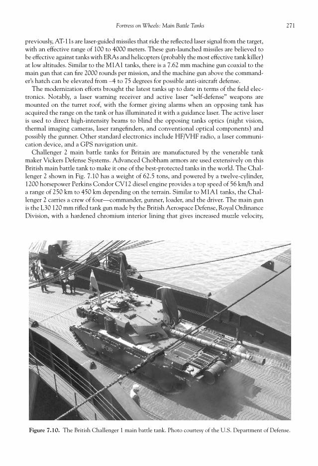
271 Fortress on Wheels: Main Battle Tanks
previously, AT-11s are laser-guided missiles that ride the refl ected laser signal from the target,with an effective range of 100 to 4000 meters. These gun-launched missiles are believed tobe effective against tanks with ERAs and helicopters (probably the most effective tank killer)at low altitudes. Similar to the M1A1 tanks, there is a 7.62 mm machine gun coaxial to themain gun that can fi re 2000 rounds per mission, and the machine gun above the command-er’s hatch can be elevated from –4 to 75 degrees for possible anti-aircraft defense.
The modernization efforts brought the latest tanks up to date in terms of the fi eld elec-tronics. Notably, a laser warning receiver and active laser “self-defense” weapons aremounted on the turret roof, with the former giving alarms when an opposing tank hasacquired the range on the tank or has illuminated it with a guidance laser. The active laseris used to direct high-intensity beams to blind the opposing tanks optics (night vision,thermal imaging cameras, laser rangefi nders, and conventional optical components) andpossibly the gunner. Other standard electronics include HF/VHF radio, a laser communi-cation device, and a GPS navigation unit.
Challenger 2 main battle tanks for Britain are manufactured by the venerable tankmaker Vickers Defense Systems. Advanced Chobham armors are used extensively on thisBritish main battle tank to make it one of the best-protected tanks in the world. The Chal-lenger 2 shown in Fig. 7.10 has a weight of 62.5 tons, and powered by a twelve-cylinder,1200 horsepower Perkins Condor CV12 diesel engine provides a top speed of 56 km/h anda range of 250 km to 450 km depending on the terrain. Similar to M1A1 tanks, the Chal-lenger 2 carries a crew of four—commander, gunner, loader, and the driver. The main gunis the L30 120 mm rifl ed tank gun made by the British Aerospace Defense, Royal OrdinanceDivision, with a hardened chromium interior lining that gives increased muzzle velocity,
Figure 7.10. The British Challenger 1 main battle tank. Photo courtesy of the U.S. Department of Defense.

272 Military Technologies of the World
precision, and reduced wear. The gun barrel itself is made of refi ned steel. The turret rotates360 degrees, while the gun elevation angle can be varied from –10 to +20 degrees. A planis in place to replace the main gun with yet more powerful Rheinemetall L55 guns.
The fi ring sequence is simplifi ed using integrated electronics. The commander can ro-tate the turret to align the gun sighted in one of the eight panoramic prisms. The gunneror the commander then moves the aiming mark in the digital display on top of the targetand clicks the laser rangefi nder. Once the onboard targeting and fi re control computerspits out a solution, the fi re button can be pressed to release the round, which then makesa thunderous exit through the barrel. The panoramic vision system used by the com-mander is a French-made gyro-stabilized VS 580-10 mounted on the turret roof. The360-degree with +/– 35 degree elevation views are available to the commander in onecommon display, and the magnifi cation of up to 10.5 can be provided with a fi eld of viewof 5 degrees. It works much like the LCD display in digital video cameras, except withpanoramic scan and control capabilities and excellent optics. The laser range fi nder con-sists of a source Nd(neodymium):YAG(yttrium aluminum garnet) laser and receiver.Nd:YAG is a commonly used lasing material used in commercial and military high-powerlasers. The laser operates at 4 Hz (number of pulses per second) and provides the distanceto the target from 200 meters to 10 kilometers with an accuracy of 5 meters. The nightand inclement weather vision is achieved with a thermal imaging unit (Model TOGS IIfrom Pilkington Optronics), with the imaging optics enclosed in an armored case abovethe gun. The thermal imaging option with magnifi cations of 4 and 11.5 can be displayedon the gunner’s and commander’s sights or on separate monitors. The gunner has an in-dependent gunner’s primary sight (GPS), as well as a telescopic view aligned with themain gun direction. The driver uses a passive driving periscope equipped with an imageintensifi cation device for night driving. The loader also has a daylight periscope, for ob-servational purposes.
The French army has the Leclerc main battle tanks and their upgrades, the Leclerc Mk2and Leclerc with the AZUR armor kit for urban operations. The AZUR kit consists of sidecomposite skirts, a rear bar armor for protection against rocket-propelled grenades, and anengine protector. Like other NATO and U.S. MBTs, the Leclerc is fi tted with a 120 mmsmoothbore main gun that has a fi ring rate of twelve rounds per minute. A standard ther-mal sleeve, muzzle reference system, and fume exhaust device using compressed air can befound on the main gun. A battlefi eld management system called FINDERS (fast informa-tion, navigation, decision, and reporting system) is installed on Leclerc tanks and includesa display showing the color map background along with host tank, friendly tanks, and op-posing tank positions. Navigation, routing, target management, and logistic planning canall be made on this system. Defensive functions like the laser warning, missile warning,and infrared jammer are integrated to the FINDERS system. Leclerc tanks also use a dieselengine, the SACM V8X-1500, for 1500 hp at 2500 rpm. The auxiliary power unit thatprovides electrical and mechanical energy independent of the main engine, however, is asmall Turbomeca TM-30 7B gas-turbine engine.
KMW (Krauss Maffei Wegmann) provides the Leopard series main battle tanks (Fig. 7.11)for the German military. The Leopard series tanks follow the lineage of highly successfulGerman tanks with over 6000 Leopard 1 tanks being built and exported since 1963 andsome 3200 Leopard 2 tanks being produced since 1979. Upgrade versions are availablewith designations Leopard 2A4, 2A5, and 2A6, among others with improved armamentsand armors including those against land mines. The main gun is the Rheinmetall WaffeMunition GmbH 120 mm L55 gun, an improvement over the previous 120 mm L44 gun.Rheinmetall 1200-mm caliber guns are adopted in many other main battle tanks aroundthe world. The L55 has a longer barrel length (6.60 meters as opposed to 5.28 meters forL44) for greater muzzle velocity (1750 meters per second) and fi res standard 120-mm caliber

273 Fortress on Wheels: Main Battle Tanks
Figure 7.11. The German Leopard AS1 tank. Photo courtesy of the U.S. Department of Defense.
Figure 7.12. A Korean-made K-1 main battle tank. Photo courtesy of the U.S. Department ofDefense.
anti-tank ammunitions including the current LKE 2 DM53 kinetic energy rounds. L55guns give an effective range of 5000 m, or just over 3 miles, so with low tank profi les inmany instances the opposing tanks would not know what hit them. Leopard tanks arepowered by MTY MB 873 diesel engines with 1500 horsepower output, with a 1650 horse-power engine envisioned for the upgrade versions.

274 Military Technologies of the World
The Israeli army has had an extensive accumulated experience in armored warfare dat-ing back to the 1960s and is currently involved in urban warfare. The unique predicamentof the Israeli military has led to an equally unique design of the main battle tank, calledMerkava. First, being a nation of a relatively small population and therefore army, the tankdesign places the highest premium on personnel protection. The heavy armor along witha highly-sloped, cast-armor turret makes the Merkava tanks diffi cult targets to penetrate atthe expense of speed. The Merkava’s top speed is estimated at 29 miles per hour, in com-parison to over 40 mph for the M1A1 tanks. Again, the relatively small region occupiedby Israel does not necessitate large speeds. The turret slope is very slanted on all sides,making it look like a turtle top, and the cast-armor angular section is fi lled with diesel fuelfor additional shock absorption. There is an inner metal casing so the diesel fi re or explo-sion hazard is external to the tank crew. Armors around the tank are of modular design sothat damaged sections can be quickly replaced. The engine and transmission are placed tothe front of the tank, again for the purpose of placing more protection for the crew.
LAST TANKS STANDING IN THE DESERT
The Israeli experiences in tank warfare are hard earned in the wide open desert and alsoin urban battles in Lebanon and elsewhere. A duel between the classic tanks occurredacross the “Bar-Lev” line along the Suez Canal that demarcated Israeli and Egyptian ter-ritories on October 6, 1973. Israelis built defensive networks consisting of bunkers and
Figure 7.13. Japanese Type 74 main battle tank. Photo courtesy of the U.S. Department of Defense.

275 Fortress on Wheels: Main Battle Tanks
strong points as well as a continuous seventy-fi ve-foot-high earthen dike along the 110-mileSuez Canal, marking the western boundary of the Sinai Peninsula seized by the Israeli forcesduring the 1967 “Six-Day War.” The attack on Israeli positions started in the afternoon witha heavy barrage of artillery shells and heavy mortar rounds along with some 200 MiG andSukhoi fi ghters from the Egyptian air force. Following the artillery barrage, 8000 Egyptianinfantrymen crossed the Suez Canal in rubber assault boats with negligible losses. Thesparse Israeli defense at the front had been neutralized by the bombing. This attack was acoordinated attempt between Syria and Egypt to recover the Sinai Peninsula, and on thenorthern front at Golan Heights the Syrian army made an attempt to breach the Israelidefense with some 1200 Soviet-made tanks (T-55s and T-62s). Against this Syrian surgein the north stood 176 Israeli tanks supported by infantry and artillery.
The beginnings of this collision of forces boded ill for the Israelis. The Egyptian infan-try, armed with new Soviet “Sagger” anti-tank missiles, began to knock out Israeli tanksone by one. The wire-guided Sagger missile with an effective range of about a mile couldfi nd the soft sides of the tanks with an alarming effectiveness against the Israeli armoredunits rushing to fi ll the gaps in the defensive positions. The Sagger missiles could be car-ried in a small case and consisted of the launch pad, the missile, and the guidance unitwith a joystick. To make matters worse, the Egyptian army engineers built effective pontoonbridges and generated twenty-foot-wide holes through the earthen dike using high-pressurewater. The bridges allowed 500 Egyptian tanks to breach the Bar-Lev line, protected by anencirclement of anti-aircraft missiles. It appeared the hectic pace and success of the mo-bile armored war, as in the Blitzkrieg and the Six Day War just six years prior, would beturned against Israel this time.
The Israeli tank forces, ordered to block the Egyptian advances, found a similar fateagainst the Sagger anti-tank missiles and rocket-propelled grenades. The Israeli tanks coulddestroy some Egyptian tanks from long range, but as the tanks drew close to the Egyptianforces infantry appeared out of foxholes and started launching Sagger missiles with devas-tating effects. Not only did these Soviet-made missiles prove to bear unprecedented effec-tiveness, but there were many of them. It is estimated that one out of three Egyptianinfantrymen carried this portable missile pack at the outbreak. When the Israeli tank crewsopened the tank hatch and started fi ring their machine guns to counter the infantry, theEgyptian soldiers responded with small-gun fi re and rocket-propelled grenades at the tankcrew. By the third day of the confl ict, the Israeli tank losses were in the hundreds. The ap-parent vulnerability of the tanks against the Egyptian anti-tank weaponry brought the Is-raeli army as close to a meltdown as there had ever been, with some tank crews abandoningtheir vehicles and others turning their tanks east for relative safety.
On the northern front, the situation on paper looked as grim with 1300 Syrian tanksbearing down on the 180-tank Israeli defense. However, the Syrian forces were not aswell coordinated with the infantry or with ditch-crossing equipment. With a quick de-ployment of reserves and using the terrain as a barrier, the Israeli army was able to slowthe Syrian movements. Although the initiative belonged to the Syrian side at the outsetdue to their numerical superiority, they failed to take full advantage by following theSoviet-styled tactics of advancing and consolidating before making further advances. Atone point, a Syrian armored brigade was ten minutes from the Israeli territory near theSea of Galilee, but the brigade commander was ordered to await reinforcements and sup-port by higher command not realizing the extent of the battle situations. During thehectic pace of the war, such gaps were godsends to the defensive forces scrambling toplug up breaches with reserves and reinforcements. The apparent discrepancy in battle-fi eld adaptability, coordinated mobility, and marksmanship is attributed to the narrowlyachieved but convincing blockage of the Syrian advances by October 9, 1973. The situation

276 Military Technologies of the World
was highly chaotic, fl uid, and precarious, but the M60Patton, the Centurion, and other tanks supplied by theUnited States and Great Britain along with the abovefactors were victorious over the Soviet-made T-55 andT-62 tanks. Every one of the Israeli tanks engaged in theGolan Heights battle took a hit, with 250 of them beingdisabled, while the Syrians lost 867 of their tanks.
In the other theater of the confl ict, the Egyptians fi -nally broke their hurdle near the east bank of the SuezCanal and brought an enormous tank formation towardthe Israeli position. This time the situation would proveto be far different than the outset. With the Israeli M48,M60, and Centurion tanks dug in behind dunes in thehigh ground, they could use the tall tank profi les and the–10 degree elevation of the main guns to bear on theEgyptian tanks, large in number but exposed in the desertlandscape. The Sagger-wielding infantry was no longer in
foxholes but also exposed to the Israeli artillery. The Egyptian force unwisely took a brutetactic of attempting to roll through the Israeli defense with sheer numerical superiority, inspite of the apparent disadvantage in the terrain. In fact, for some unknown reason theEgyptian tanks did not even attempt to fi re at the Israeli tanks. Moreover, their advanceswere not coordinated—separate forces advanced at nine different points with no apparenttiming—and the Israeli tanks could simply shift to the point of attack and deal with themone by one, thus negating some of the numerical disadvantage. The result was an enormousshootout where the recipients of the shells were invariably on the Egyptian side with 400disabled tanks on the Egyptian side in one day of battle.
Less than two decades later, another confrontation between two massive tank armieswould unfold in the desert, this time far to the west on the Kuwait-Iraq border. Desertlandscape with its sheer mass and diffi cult terrain tends to highlight the effectiveness oftanks as war vehicles. To dislodge the Iraqi army occupying Kuwait and its oil fi elds, theU.S.-led coalition forces started with air and artillery bombardments of the Iraqi positions.The bombing certainly disabled the command and control infrastructure as well as thesupply lines, and severely depleted and demoralized the Iraqi troops on the ground. Yet,the actual operation of removing the Iraqi troops from the occupied Kuwait fell on thecoalition ground forces. The Iraqi army was more or less equally divided in number be-tween the regular army and the elite Republican Guard, each with 30,000 to 40,000 troops.Both were in turn divided into three types of divisions—armored, mechanized, and infan-try, with the armored divisions employing mostly Russian-made tanks ranging from theT-54 and T-55 to the T-69 and also the T-72 (see Figs. 7.16 and 7.17). The T-72 tanks wereconsidered a top-line Soviet tank, and Iraq had developed suffi cient industrial basis toproduce these tanks on their own. They were called the “Babylon Lion.” The T-72 tankswere considered capable of dealing with most western tanks seen up to that date. Of course,the military observers had not seen the U.S.-made M1 Abrams tanks in action up to thatdate nor the coordinated attacks by Bradley fi ghting vehicles or tank-killer helicopters likethe Apache wielding long-range anti-tank missiles. In fact, the world had not seen U.S.armored division movements of this scale since World War II. The new armored warfaredoctrine was developed after the Vietnam War. Each U.S. Army “heavy” brigade had twoor three battalions of M1A1 Abrams tanks (fi fty-eight per battalion), one battalion of fi f-ty-four M2A2 Bradley fi ghting vehicles, and a cavalry squadron of M3 Bradleys and OH-58D scout helicopters. Each of the battalions had a separate scout platoon, a mortar
Figure 7.14. A long-rod anti-tank penetra-tor at the time of sabot separation. Photocourtesy of the U.S. Army.

277 Fortress on Wheels: Main Battle Tanks
platoon, and fuel, ammunition, and maintenance units. In addition, the battalions weresupported at the division level by a fi re support team, a Stinger air defense system, andengineering platoons. Essentially all that is necessary to wage a tank war went with theU.S. heavy brigades.
The fi re support moving with the U.S. heavy brigade consisted of twenty-four M109A2self-propelled artillery systems, along with command track vehicles, fuel and ammunitiontrucks, and tracked ammunition carriers. In addition, multiple-launch rocket systems werecarried as a part of the fi re support. An aviation brigade with two battalions of AH-64Apache tank-killer helicopters, a company of UH-60 Black Hawks, and a platoon of OH-58D scout helicopters traveled with the U.S. armored units. Thus, a U.S. armored divisionwith all of the fi ghting and support troops and vehicles occupied a desert area from 25 to
Figure 7.15. A schematic of a HEAT round.
Figure 7.16. A destroyed T-55 Russian-made tank. Photo courtesy of the U.S. Department of Defense.

278 Military Technologies of the World
45 km wide and 80 to 150 km deep, with more than 22,000 troops and close to 2000tracked vehicles. A tremendous amount of fi repower and war-waging capabilities are inthe hands of a U.S. armored division commander.
So on February 24, 1991, the two massive tank armies stood across the Kuwait–SaudiArabia border. The coalition plan, essentially drawn out by the U.S. military, was to breachthe Iraqi frontline defense and at the same time perform a fl anking movement toward theelite Republican Guard units while choking off the retreat by closing “Highway 8,” themain arterial road to Iraq. Not only was Kuwait to be liberated, but the Iraqi RepublicanGuard and other units were to be thoroughly destroyed. Prior to the attack, massive vol-leys of artillery fi re and rockets from multiple launch systems were dropped on the Iraqifrontline positions. The armored thrust started at 3:00 PM with a 6000-meter-wide wall ofmetal and fi re. With the lead tank battalions fi ring with their 120 mm high-explosiverounds, Bradleys fi ring machine guns, and combat engineer tracked vehicles pounding thebunkers and any hardened defensive positions with 165 mm guns, the modern-day pha-lanx did not allow anyone or anything to stand in its path. Mine-clearing vehicles andarmored earthmovers paved the way for other vehicles to continue this rush of fi re andmetal. Once the trenches were breached, the infantry simply rounded up the stunnedIraqis. By 4:15 PM , sixteen lanes were cleared across the trench lines.
The encounter with the elite Republican Guard armored units occurred two days later.First the attack helicopter battalions were sent in to knock out the artillery and othertargets of interest deep in the enemy side. One critical weakness of any tank without aux-iliary anti-aircraft defense is its vulnerability to helicopter-fi red missiles. Tanks do nothave guns that can fi re at any appreciable elevation, nor any sensors to detect airborneattack. The physical clash commenced with the U.S. initiative at 10 PM on February 26. Aformation of M1 Abrams tanks and Bradley vehicles delivered a well-coordinated attackon the positions held by the Iraqi Republication Guard. Armed with thermal sights and
Figure 7.17. A destroyed T-72 Russian-made tank. Photo courtesy of the U.S. Department of Defense.

279 Fortress on Wheels: Main Battle Tanks
night-time fi re capabilities, the U.S. tanks could almost at leisure pick out multiple enemytanks with ineffective return fi re from the other side, who could not see what was going onin the dark of the night. The attack and scout helicopters were also equipped with nightvision and targeting capabilities. Any artillery fi re from the Iraqi side registered strongthermal signatures from the muzzle heat, and these pieces were knocked out or silenced.Bradley fi ghting vehicles, although lightly armored and without a main gun, fi red TOW(tube launched, optically tracked, wire-guided) missiles with long-range accuracy and cer-tain lethality. TOW missiles fi red from the Bradleys routinely engaged and hit targets from3300 meters, or more than two miles, away. At this range, a Bradley crew more than oncewatched the return fi re, if any, by the Iraqi T-72 tanks land harmlessly in the sand wellahead of their vehicles. By the early morning of the next day, all that remained of theenemy side was two battalions’ worth of wreckage of the Iraqi tanks and other hardware.
The weight of the coordinated air-land coalition forces was simply overwhelming forthe Iraqi military still operating in the one-dimensional strategic fi eld. Although dug intobunkers and tank trenches with enormous stockpiles of ammunition, the Iraqi tanks weresitting ducks against the Apache-fi red anti-tank missiles and long-range main guns ofthe M1 Abrams tanks. The Abrams tanks were fi ring and hitting from ranges beyondthe T-72s, which were dug in too deep to elevate their guns for effective fi re to beginwith. The result was of course a near complete annihilation of the Iraqi army, stopped onlythrough a political decision to limit the coalition thrust to outside of the Iraq territory. Atthe time, the Bush administration was criticized for not fi nishing the job and not fullydestroying the Iraqi military and political structure. However, history would prove laterthat it was indeed a well-thought-out decision and the operational objective of freeingKuwait was attained with minimal losses on the coalition side. Superior strategy, bettertechnology in military equipment, coordination of all dimensions of the attack, and trainingof the troops combined with a world-supported imperative to restore order in the regionproved to be the winning formula.
TANK POWER TRAIN
As noted above, most MBTs in the world use turbocharged diesel engines, with the U.S.M1-series using gas-turbine engines. Gas-turbine engines produce high power per engineweight but are subject to maintenance issues and high fuel consumption. Diesel enginesare turbocharged to increase the power output from an engine of given volume and weight.The power output from internal combustion engines is proportional to the engine dis-placement (combustion chamber volume) and operating pressure. A compressor is run offof the power generated by a turbine, which in turn is rotated by the engine exhaust gas.Engine exhaust gas is at a much higher temperature than the ambient air, and the excessenergy (and pressure) can be used to run the turbines. Compression of the intake air isaccompanied by a temperature increase, which tends to decrease the air density or air massper burn cycle. Thus, a typical “intercooler” is used to lower the temperature before the airis sent into the combustion chamber. The term “supercharging” is used if the compressoris run off the main engine output, which then uses more fuel per power output than turbo-charging. Typical diesel engines consume about 20 percent less than comparable gas-turbineengines, with fuel rate of approximately 110 kg/hour for a 500 kW output. A regenerativegas-turbine engine may use up fuel in excess of 130 kg/hour.
A one ton or 1000 kg mass is subject to a force of 9810 N (Newtons) due to gravity. Therolling resistance of objects, including tank tracks, depends on the weight, and therefore afi fty-fi ve-ton tank with a weight of 540,000 N will have to overcome about 43,200 N of

280 Military Technologies of the World
ground resistance, assuming a coeffi cient of rolling resistance of 8 percent of the weight.That means the engine has to provide an instantaneous torque or thrust of this magnitude.If a speed of, say 45 mph, which is 20 m/s, is to be maintained, then the required power isthe amount of force multiplied by the speed, giving us 864 kW. Actual tank operationobviously involves traversing upgrades and other obstacles, which will add to the requiredpower, and thus most MBTs are powered with engines in the neighborhood of 1120 kW or1500 horsepower. For a fuel consumption rate of 110 kg/h for a 500 kW diesel engine, thespecifi c fuel consumption (the fuel consumption per kW of power output) is 110kg/h/500kW or 0.22 kg/kWh, so for an 864 kW power output the fuel consumption would be 864kW× 0.22kg/kWh or 190 kg/h. For a full 1120 kW power, this would be increased to 246 kg/h.In either case, at a speed of 45 mph the fuel mileage is then 0.24 mile per kg (864 kW) and0.18 mile per kg (1500 kW). Converting to the more familiar mile-per-gallon using 3.41 kgper gallon of diesel fuel, we get 0.82 mpg for 864 kW or 0.62 mpg for 1120 kW. For gas-turbine engines, mileage is even less, and in fact the above calculations are for a smoothrolling surface at zero incline so gas mileage can drop rapidly under actual conditions.
The basic tank transmission using a change-speed gearbox is similar in principle to theautomotive versions, as shown in Fig. 7.18. There are the input, counter, and output shaftsand two transmission clutches, along with a number of “spur” gears with different driveratios. The drive ratio determines the output torque, and the gears themselves may bestraight-cut, single helical, or double helical teeth. At low gear, the power is transmittedvia A-B-E-J with both of the clutches X and Y disengaged. The E-J gear combination hasthe largest drive ratio for high torque. Second-gear operation is achieved through A-B-D-Hwith clutch X disengaged but Y engaged. The third gear runs via A-B-C-G with clutch Xnow engaging the G gear. The highest speed gear operation is performed though clutchesX and Y transmitting power from the input to the output shaft directly. The reverse gear Kis engaged with an intermediate gear between the counter and output shafts. The U.S.M1-series tanks, for example, use an Allison X-1100-3B automatic transmission that pro-vides four forward and two reverse speeds. Other main battle tanks also use either four orfi ve forward and two reverse gears, as in the French Leclerc tank with an SESM ESM 500automatic transmission with a hydrokinetic transmission unit and fi ve forward and tworeverse gears. Additional speeds can be produced by adding clutches and gears. Hydroki-netic coupling transfers power from the engine to the power shaft for smooth transitions
Figure 7.18. A schematic of a four-speed transmission.

281 Fortress on Wheels: Main Battle Tanks
and isolations of shocks in place of friction or centrifugal clutches. The engine drives theimpeller vanes with the hydrokinetic coupling fi lled with transmission oil, and the turbinereceives the kinetic energy created by the impeller and turns the power shaft.
TRACKS
The tracked armored vehicles were invented to provide an ability to attack in poorground conditions including ditches, barbed wires, obstacles, and enemy fi re. The tracksdistribute the weight of the armored vehicle under these conditions by taking full advan-tage of the drive torque and maximizing the traction. On hard surfaces, the main rollingresistance comes from the track itself, between the track, track components, and the roaditself. On soft surfaces, resistance is increased due to sinkage. By using wide tracks, theweight of the vehicle is distributed to avoid local extremes in ground stress that may resultin vertical or horizontal shearing. In addition, the track components must be resistant tofailures and easy to replace. Some of the main track components are shown in Fig. 7.19.The road performance is not limited to the tracking ability in modern main battle tanks.To improve the crew comfort and effi ciency, ride comfort is recognized as one of the impor-tant elements in track design. In numerous tank battles, this aspect has emerged as a criti-cal factor in maintaining crew performance and judgment. It is also evident that since mostMBTs need to fi re the main guns during high-speed moves, a stable gun platform needs tobe provided by the track and suspension in addition to the gun and sight stabilization be-cause the latter can only compensate for some of the fl uctuations in the tank elevation andyaw angles. For similar tactical reasons, handling capabilities of the tracks are important inguiding the tank in the intended directions at various speeds and ground conditions.
The track itself consists of the track plates connected to one another via connectingpin-lug links. Single- or double-pin link designs are available with rubber padding. Thedouble-pin tracks tend to be more elastic and require the track to be run at higher tensionto avoid sprocket slip. Double-pin track links have a higher mileage—close to 10,000 km—but weigh more than single-pin tracks (about 10 percent of the tank weight may be de-voted to the tracks). For the road wheels, solid rubber wheels are used, with a groove in themiddle that follows the “horn” protruding from the track plates. There are typically bothstatic and dynamic tension adjustments between the idler and the front-most road wheel.
Figure 7.19. Tank wheel confi guration.
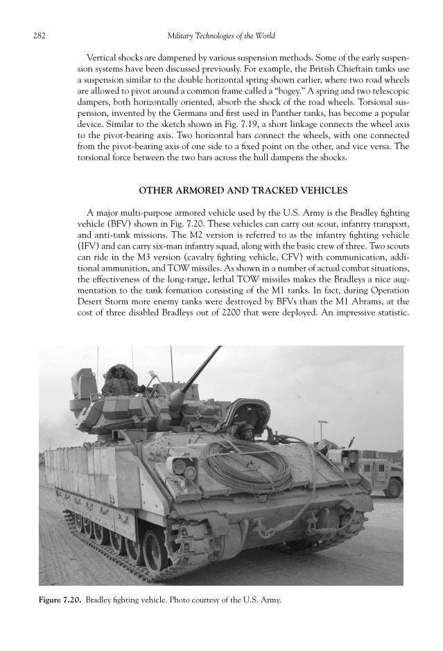
282 Military Technologies of the World
Vertical shocks are dampened by various suspension methods. Some of the early suspen-sion systems have been discussed previously. For example, the British Chieftain tanks usea suspension similar to the double horizontal spring shown earlier, where two road wheelsare allowed to pivot around a common frame called a “bogey.” A spring and two telescopicdampers, both horizontally oriented, absorb the shock of the road wheels. Torsional sus-pension, invented by the Germans and fi rst used in Panther tanks, has become a populardevice. Similar to the sketch shown in Fig. 7.19, a short linkage connects the wheel axisto the pivot-bearing axis. Two horizontal bars connect the wheels, with one connectedfrom the pivot-bearing axis of one side to a fi xed point on the other, and vice versa. Thetorsional force between the two bars across the hull dampens the shocks.
OTHER ARMORED AND TRACKED VEHICLES
A major multi-purpose armored vehicle used by the U.S. Army is the Bradley fi ghtingvehicle (BFV) shown in Fig. 7.20. These vehicles can carry out scout, infantry transport,and anti-tank missions. The M2 version is referred to as the infantry fi ghting vehicle(IFV) and can carry six-man infantry squad, along with the basic crew of three. Two scoutscan ride in the M3 version (cavalry fi ghting vehicle, CFV) with communication, addi-tional ammunition, and TOW missiles. As shown in a number of actual combat situations,the effectiveness of the long-range, lethal TOW missiles makes the Bradleys a nice aug-mentation to the tank formation consisting of the M1 tanks. In fact, during OperationDesert Storm more enemy tanks were destroyed by BFVs than the M1 Abrams, at thecost of three disabled Bradleys out of 2200 that were deployed. An impressive statistic.
Figure 7.20. Bradley fi ghting vehicle. Photo courtesy of the U.S. Army.
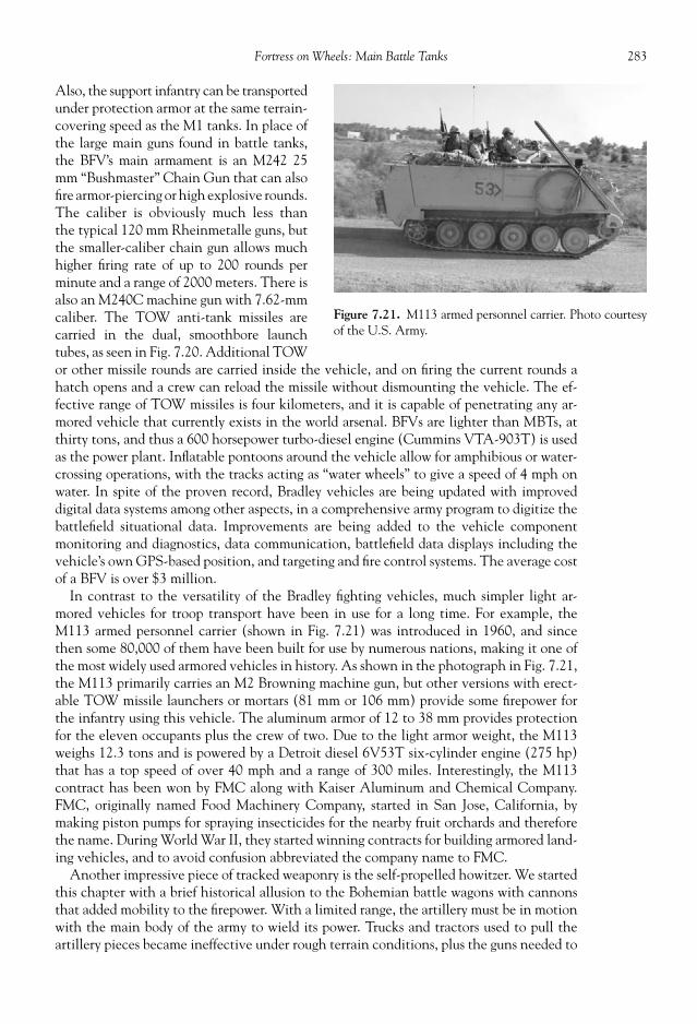
283 Fortress on Wheels: Main Battle Tanks
Also, the support infantry can be transportedunder protection armor at the same terrain-covering speed as the M1 tanks. In place ofthe large main guns found in battle tanks,the BFV’s main armament is an M242 25mm “Bushmaster” Chain Gun that can alsofi re armor-piercing or high explosive rounds.The caliber is obviously much less thanthe typical 120 mm Rheinmetalle guns, butthe smaller-caliber chain gun allows muchhigher fi ring rate of up to 200 rounds perminute and a range of 2000 meters. There isalso an M240C machine gun with 7.62-mmcaliber. The TOW anti-tank missiles arecarried in the dual, smoothbore launchtubes, as seen in Fig. 7.20. Additional TOWor other missile rounds are carried inside the vehicle, and on fi ring the current rounds ahatch opens and a crew can reload the missile without dismounting the vehicle. The ef-fective range of TOW missiles is four kilometers, and it is capable of penetrating any ar-mored vehicle that currently exists in the world arsenal. BFVs are lighter than MBTs, atthirty tons, and thus a 600 horsepower turbo-diesel engine (Cummins VTA-903T) is usedas the power plant. Infl atable pontoons around the vehicle allow for amphibious or water-crossing operations, with the tracks acting as “water wheels” to give a speed of 4 mph onwater. In spite of the proven record, Bradley vehicles are being updated with improveddigital data systems among other aspects, in a comprehensive army program to digitize thebattlefi eld situational data. Improvements are being added to the vehicle componentmonitoring and diagnostics, data communication, battlefi eld data displays including thevehicle’s own GPS-based position, and targeting and fi re control systems. The average costof a BFV is over $3 million.
In contrast to the versatility of the Bradley fi ghting vehicles, much simpler light ar-mored vehicles for troop transport have been in use for a long time. For example, theM113 armed personnel carrier (shown in Fig. 7.21) was introduced in 1960, and sincethen some 80,000 of them have been built for use by numerous nations, making it one ofthe most widely used armored vehicles in history. As shown in the photograph in Fig. 7.21,the M113 primarily carries an M2 Browning machine gun, but other versions with erect-able TOW missile launchers or mortars (81 mm or 106 mm) provide some fi repower forthe infantry using this vehicle. The aluminum armor of 12 to 38 mm provides protectionfor the eleven occupants plus the crew of two. Due to the light armor weight, the M113weighs 12.3 tons and is powered by a Detroit diesel 6V53T six-cylinder engine (275 hp)that has a top speed of over 40 mph and a range of 300 miles. Interestingly, the M113contract has been won by FMC along with Kaiser Aluminum and Chemical Company.FMC, originally named Food Machinery Company, started in San Jose, California, bymaking piston pumps for spraying insecticides for the nearby fruit orchards and thereforethe name. During World War II, they started winning contracts for building armored land-ing vehicles, and to avoid confusion abbreviated the company name to FMC.
Another impressive piece of tracked weaponry is the self-propelled howitzer. We startedthis chapter with a brief historical allusion to the Bohemian battle wagons with cannonsthat added mobility to the fi repower. With a limited range, the artillery must be in motionwith the main body of the army to wield its power. Trucks and tractors used to pull theartillery pieces became ineffective under rough terrain conditions, plus the guns needed to
Figure 7.21. M113 armed personnel carrier. Photo courtesyof the U.S. Army.

284 Military Technologies of the World
be put in proper settings once they were unfastened from the transport vehicles. Self-propelled gun vehicles overcome these limitations by placing the heavy guns in trackedvehicles with all the crew and ammunition being carried along in the same platform. Mis-sion requirements result in different designs for these self-propelled guns, but the outcomeis a highly mobile unit that can easily be coordinated in complex army operations. TheSwedish design, for example, includes an auto-loader mechanism to save the need tohave a loader on board, while the Russian design allows only direct, fl at-trajectory fi ring ofthe guns. The representative vehicle for the U.S. Army is the M109A6 Paladin self-propelled howitzer (see Fig. 7.22). Its appearance resembles a battle tank, except with a
much bigger gun and lighter armor. The Kevlar-lined body protects the crew against small-arm fi resand fragments. The operational crew is actuallysimilar to a tank, with the forward driver, com-mander, gunner, and loader in the fi ring cabin. TheM284 150 mm cannon can be fi red at up to fourrounds per minute with a range of 30 km. The on-board night vision, navigational, and fi re controlsystems allow the crew to operate autonomouslyonce the target coordinates are communicated. Allthe functions, including the detachment of thegun-securing lock for travel, are remote controlledso that the crew can operate within the confi nes ofthe vehicle. The container in the back of the vehicle
Figure 7.22. M109A6 Paladin self-propelled how-itzer. Photo courtesy of the U.S. Army.
Figure 7.23. The French Giat 155 mm AUF1 self-propelled gun. Photo courtesy of the U.S. Department ofDefense.

285 Fortress on Wheels: Main Battle Tanks
carries ammunition and charges. The mobility allows the crew to set up for fi ring in sixtyseconds and after the fi ring mission move to alternate locations to evade counter-artillerybarrages.
An alternate mobile platform launching rocket-based warheads is the M270 multiplelaunch rocket system (MLRS). The MLRS is mounted on M993 tracked vehicle that cantravel at 40 mph. Two launch modules with six M26 rockets each are carried on this ve-hicle. M26 rockets are large boosters close to thirteen feet in length and nine inches indiameter, with a range of 20 miles (32 km). A number of different warheads can be in-stalled on the M26, such as the M77 primary warhead with 644 submunitions, the XR-M77 with extended range (to 25 miles or 40 km), AT-2 parachute-retarded anti-tankmines, SADARM (sense-and-destroy armor) with a sensor for armored vehicles thatguides three submunitions to these targets during descent, and TGW (terminally guidedwarhead).
Finally, a wheeled vehicle that became synonymous with the army mobility and tough-ness is the “high-mobility multipurpose wheeled vehicle” (HMMWV), better known asthe “Humvee” or “Hummer.” As the name suggests, it is a utility vehicle that is used by allbranches of the U.S. military and has performed any task one can think of from carryingoffi cers, scouting in rough terrains, and acting as an ambulance, TOW missile fi ring plat-form, and Stinger anti-aircraft missile launch platform. With a base weight of approxi-mately 5000 pounds, the Humvees are powered by a General Motors eight-cylinder6.5-liter diesel engine. Incredibly to some observers, this vehicle was marketed for thegeneral public by General Motors and at one time was one of the most popular four-wheeled vehicles in the commercial sector in spite of its over-design for urban drivingconditions and extremely low gas mileage (typically less than 10 mpg).
REFERENCES
Clancy, Tom. Armored Cav, A Guided Tour of an Armored Cavalry Regiment . New York: BerkeleyBooks, 1994.
Hofmann, G.F., and D.A. Starry (eds.). Camp Colt to Desert Storm, The History of U.S. ArmoredForces . Lexington, KY: University Press of Kentucky, 1999.
Macksey, Kenneth, and Johan H. Batchelor. Tank, A History of the Armored Fighting Vehicles . NewYork: Charles Scribner’s Sons, 1970.
Miller, David. The Illustrated Directory of Tanks of the World, From World War I to the Present Day .Minneapolis, MN: MBI Publishing Company, 2000.
Terry, T.W., S.R. Jackson, C.E.S. Ryley, B.E. Jones, and P.J.H.Wormell. Fighting Vehicles, Landy War-fare: Brassey’s New Battlefi eld Weapons Systems and Technology Series . London, UK: Brassey’s,1991.
Time Life Books. The Armored Fist, A New Face of War . New York: Time Life Books, 1990. For more information on the kinetic energy penetrator, see en.wikipedia.org/wiki/Kinetic_energy_
penetrator.

This page intentionally left blank
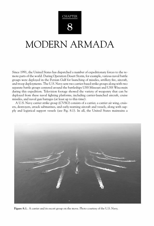
Since 1991, the United States has dispatched a number of expeditionary forces to the re-mote parts of the world. During Operation Desert Storm, for example, various naval battlegroups were deployed in the Persian Gulf for launching of missiles, artillery fi re, aircraft,and troop deployments. The U.S. Navy sent two carrier-based strike groups along with twoseparate battle groups centered around the battleships USS Missouri and USS Wisconsinduring this expedition. Television footage showed the variety of weaponry that can bedeployed from these naval fi ghting platforms, including carrier-launched aircraft, cruisemissiles, and naval gun barrages (at least up to this time).
A U.S. Navy carrier strike group (CVSG) consists of a carrier, a carrier air wing, cruis-ers, destroyers, attack submarines, and early-warning aircraft and vessels, along with sup-ply and logistical support vessels (see Fig. 8.1). In all, the United States maintains a
CHAPTER
8
MODERN ARMADA
Figure 8.1. A carrier and its escort group on the move. Photo courtesy of the U.S. Navy.

288 Military Technologies of the World
number (twelve as of 2007) of these carrierstrike groups, with six of them being readyfor deployment within thirty days. The car-rier maintains an ability take air strikes toany part of the world by maneuvering thecarrier in international waters in the vicin-ity of the confl ict region. It bypasses theneed to acquire landing rights on foreignsoil. With a nuclear reactor powering thecarrier, the carrier strike group can traveland maintain engagements over extendedperiods of time. The carrier air wing in turnmay include several naval air squadrons witha fl eet of F/A-18 fi ghter-bombers, attack air-craft, and electronic warfare airplanes. Othercomponents in the strike group protect the
carrier and add to the overall mission capabilities. Two guided missile cruisers, typically apart of the strike group, are equipped with Tomahawk cruise missiles for long-range strikecapabilities along with defensive missiles, and they also carry multi-mission surface com-batants. A guided missile destroyer guards against airborne attacks on the strike group. Ananti-submarine warfare (ASW) destroyer and a frigate patrol the waters to seek out anddestroy encroaching submarines. Two attack submarines also accompany the strike groupfor anti-ship and anti-submarine warfare. As noted previously, a number of supply andlogistical support vessels and early-warning radar aircraft make up the remainder of thecarrier strike group. There may be 6500 sailors manning these ships in the group alongwith pilots and surface troops.
The main components of the Eisenhower carrier strike group, for example, may consistof the USS Eisenhower aircraft carrier (CVN-65) itself; the carrier air wing (CVW-7); theguided missile cruiser USS Anzio (CG-68); two guided missile destroyers, the USS Ramage(DDG-61) and USS Mason (DDG-87); and an attack submarine, the USS Alexandria(SSN-750). A photograph of the USS Eisenhower seen from the air is shown in Fig. 8.2.A carrier strike group can also be accompanied by destroyers (DD) or guided missile frig-ates (FFG). All together, a strike group may be spread out over 30,000 square miles withsome eighty-fi ve aircraft extending the range of operation. Early warning aircraft, radars,and sonar monitor a vast three-dimensional volume of space around the strike group, andthe carrier-based task force commands this space with a huge arsenal of weaponry. Sincetwo-thirds of the earth is covered with oceans, the ability to send expeditionary forces ofthis magnitude equals an ability to wield commanding military infl uences all over theworld. Table 8.1 shows the typical components of the U.S. carrier strike groups using theabove ship designations.
A BRIEF HISTORY OF WARSHIPS
The origin of warships with big guns arose from the classic naval battles of the nine-teenth century, where the ships formed a “line of battle” to maximize the use of theirbroadside guns. The seamanship and gunmanship were essential factors in winning theseferocious battles, where the discipline and sheer guts to engage the guns while beingpounded by incoming cannonballs with all their wood-splintering and maiming devasta-tions, often determined the outcome. Naval supremacy meant world domination in that
Figure 8.2. A photo of the USS Enterprise aircraft carrieras seen from the air. Photo courtesy of the U.S. Navy.

289Modern Armada
age of newfound worlds, to ensure continuation of profi table trades, supplying remote co-lonial outposts, and protecting against rival encroachments on these territories. Clashes ofnaval forces on the open sea through sheer exchange of gunfi re meant that bigger shipscapable of carrying more and bigger guns ensured technical supremacy. There were canonsfi ring forty-two-pound balls, demi-cannons with thirty-two-pounders, culverins with eigh-teen-pounders, and demi-culverines with nine-pounders. Multi-decked ships with 100guns called the First Rates were the fl agships of the European navies, with three-deckedSecond Rates carrying ninety to ninety-eight guns and two-decked Third Rates with sixty-four to eighty-four guns.
In one of the classic battles of wooden ships with big guns, the French-Spanish coalitionfl eet with giant 130-, 112-, and 110-gun ships clashed with the British Royal Navy fl eet ledby Lord Nelson in what is known as the Battle of Trafalgar in 1805. The French-Spanishfl eet was ordered to break through Nelson’s line so that Napoleon could lead an invasionforce across the English Channel, which would require naval supremacy so that the land-ing force could move across the Channel unmolested. Although the coalition fl eet wassuperior in number and size, it lacked a competent offi cer corps because many capableFrench naval offi cers were executed or ousted during the earlier French Revolution. More-over, its commander, Admiral Villeneuve, was less than enthusiastic about fi ghting anynavy bearing the name of Nelson after having suffered losses at the British admiral’s hand.
Table 8.1. The U.S. Carrier Strike Groups and Their Typical Components as of 2007.
CarrierCarrier
Air Wing
GuidedMissileCruiser
GuidedMissile
Destroyer Destroyer
GuidedMissileFrigates
AttackSubmarines
Lincoln CVW-14 CG-53 DDG-60 DD-992 FFG-37 SSN-718CG-67 FFG-57
Constellation CVW-2 CG-50 DDG-69 DD-965 FFG-43 SSN-771CG-52 DDG-76
Truman CVW-3 CG-56 DDG-57 DD-977 FFG-53 SSN-720DDG-75 DD-989 SSN-765DDG79
Roosevelt CVW-8 CG-68 DDG-51 N/A FFG-52 N/ACG-71 DDG-78
DDG-81
Kitty Hawk CVW-5 CG-62 DDG-56 DD-975 FFG-48 SSN-698CG-63 DD-985 FFG-51
Vinson CVW-9 CG-52 DDG-82 N/A FFG-54 N/AFFG-60
Nimitz CVW-11 CG-59 DDG-53 DD-972 FFG-60 SSN-752CG-65 DDG-62
DDG-65
Enterprise CVW-1 CG-58 N/A DD-13 N/A SSN-706CG-64
Stennis CVW-14 CG-57 DDG-83 N/A FFG-54 SSN-716Kennedy CVW-17 CG-66 DDG-64 DD-963 FFG-36 N/A
CG-69 DDG-68 FFG-50DDG-80
290 Military Technologies of the World
Instead of taking the conventional parallel line approach, Nelson’s game plan was not tosimply engage but to demolish the coalition fl eet. To do so, a strategy with calculated riskwas formulated wherein Nelson formed two separate lines out of his ships with one to at-tack the middle of the coalition line of battle and the other to enclose the rear of the line.By cutting the coalition line in half, a melee of ship-to-ship battles would break out inwhich more experienced British crews would prevail. The risk was of course splitting analready inferior fl eet in two and on top of it exposing the ships to the coalition fi re duringthe approach right to the middle of their line of battle. Indeed, the fi rst ships to approachthe French-Spanish line of ships were raked with cannon fi re. After all, Nelson’s fl eet wasoutnumbered 17,000 men to 30,000 and 2148 guns to the 2568 of the coalition fl eet, inaddition to lacking 100-plus guns ships (three against fi ve). The fi rst two lead ships wereseverely damaged, and the third ship in the attack line, Victory, was close to being overrunby boarding parties of the French Redoubtable until the British Temeraire came along onthe other side just in the nick of time to fi re a devastating salvo on the Redoubtable. Dur-ing this engagement, a stray musket shot hit Nelson himself, and he would later die fromthe wound. The battle raged on with each arrival of a British ship raking methodical can-non fi re in the midst of the coalition fl eet. The confusion of the battle meant that theadvantage turned to the British side with its gutsy marksmanship. The end result wastwenty-two of the coalition ships lost against none on the British side. The invasion ofBritain came to naught, but more important, sea power remained in the British hands forsome years to come to give rise to the emergence of the British Empire.
The importance of naval supremacy accelerated the growth of the imperial navies. Inaddition to larger numbers and sizes of the ships, technological advances found good ap-plications in naval vessels. The shell rounds with a simple time-delay wood fuse could inprinciple wield much more fearsome damage, with an explosive charge in the shell thatcould set fi re to wooden ships as well as delivering more explosive impact. However, dueto its wobbling trajectory (rifl ed guns with spiral grooves would come later) the accuracyof the shell rounds was inferior to simple cannon balls, and by 1830 only 40 percent of theguns in three-deck warships were of the type to fi re shell rounds. Steam engines withpaddle wheels obviously had the advantage of propulsion regardless of the wind conditionand the potential to provide much better speed. Again, because the paddle wheel inter-fered with the operation of the broadside guns its use in large warships was delayed untilscrewed propulsion was invented. The fi rst screw-propulsion battleship was the BritishThird Rate Ajax in 1846. However, the ships were still made out of wood, and shell rounds,now developed into viable naval weapons, now started taking devastating tolls on shiphulls regardless of the relative size of the ships. A suggestion by French “Directeur du Ma-teriel” to line the hull with unused cannon balls was fortunately quickly dismissed, andinstead the Royal Navy came up with a much more sensible plan of plating the hull with4-inch-thick iron plates. The fi rst of the “ironclads” like the British “Aetna” and later theFrench “Congreve” were so weighed down by this thick armor that they had to be towedto the engagement areas. However, they did prove to be impervious to the round shells ofthat time (mid-nineteenth century). Soon the naval architectural and metallurgical tech-nology of Britain brought up to speed the iron-hulled “Warrior” with enough steam powerto move itself and watertight iron bulkheads. The practice of lining up the guns on thebroadside meant that ships had to be of a certain length to mount a large number of guns.The idea of rotating gun turrets can be traced to a Swedish engineer, John Ericsson, and aRoyal Navy captain, Cowper Coles. A prototype armored turret placed on a small vesselwas fi red on thirty-three times by heavy shells and still continued to function, and thatmarked the beginning of ironclads with turret guns. Machine power propulsion, ironarmor, and turret guns soon became the standard in naval warships, with major imperialistic

291Modern Armada
nations of the time racing to add bigger warships with bigger guns. By the beginning of1900s, breech-loading guns with twelve-inch or bigger caliber could be found in largernaval vessels. The trend to engage other naval warships with bigger guns continued untilWorld War II, when aircraft carriers altered the entire paradigm of naval battles.
TYPES OF WARSHIPS
Naval vessels with tonnage from 2000 to 8000 are loosely referred to as destroyers andfrigates. The distinction between destroyers and frigates also varies from one navy to theother, but the frigates tend to be smaller than destroyers. There is also a smaller class ofships called “corvettes” and mine warfare ships, typically below 1000 tons. A destroyer orfrigate can be assigned a range of missions from anti-air to anti-surface or anti-submarinewarfare, depending on the armament and sensor equipment that it carries. A destroyer bydesign needs to be fast and maneuverable and yet have a large range to escort and protectcarriers against air, surface, and submarine attacks. A Spruance-class destroyer in the U.S.Navy, DD-985 Cushing, is shown in Fig. 8.3. The U.S. Navy has thirty-plus of these de-stroyers, and the displacement is 5770 tons. To give an idea as to its dimensions, Spruance-class destroyers have a length of 583.2 feet (172 meters), width of 55.1 feet (16.8 meters),and a hull height of 29 feet (8.8 meters). The propulsion power comes from four GeneralElectric dual-shaft gas-turbine engines (GE LM2500) with a total of 80,000 hp output thatpropels the ship at 33 knots. Marine vessels use the unit of knots, 1 nautical mile per hour,which converts to 1.14 mph or 1.852 km/hr. The estimated range is 6000 nm (nauticalmiles) at a cruise speed of 20 knots.
A number of weapons can be carried on Spruance-type destroyers. A fi ve-inch Mk45 dual-purpose gun can be seen in the photograph on the front part of the ship. The same gun canbe found on the rear of the destroyer. Although not visible in the photograph, an ASROC(anti-submarine rocket) launcher with eight tubes is typically used for anti-submarine war-fare. Based on the sonar detection of a submarine target, the missile is launched through theair fi rst to the vicinity of the target range and bearing. The payload torpedo separates fromthe missile in air with a parachute to soften the torpedo entry into the water. The torpedothen is under its own sonar guidance to strike the target submarine. The range of the ASROCis about 6 nm (nautical miles), and either an Mk 46 torpedo with 100 lb of PBXN-103 highexplosive or a 1 kT nuclear depth charge can be carried. The Mk 32 ASW torpedo launchsystems can also be used against submarines.Unlike ASROC, the torpedoes are launchedpneumatically with a much smaller range ofdeployment. In addition, Harpoon surface-to-surface missiles are used against surface ships.For air defense, the Mk 15 20 mm Vulcan/Phalanx cannons and Mk 29 launcher forsurface-to-air missiles are available.
Some of the sensors are visible on the twomounts. A round sphere on the lower sensormast beam is the SPG-60 radar illuminatorfor Mk 86 fi re control systems, while theradar dish just above it is the SPS-55 searchradar. Close to the top, an SPS-40 air searchradar guards against aircraft approaches.Other radars on the second mast include the
Figure 8.3. A photo of the USS Cushing (DD-985), aSpruance-class destroyer. Photo courtesy of the U.S. Navy.

292 Military Technologies of the World
SPG-55D missile control radar, the SLP-32 early warning system, and the SPS-48A three-dimensional radar. Although not visible, there are sonars like the hull-mounted SQS-53 andSQR-19 TACTAS. TACTAS stands for “tactical towed array sonar” and represents a passivesonar listening device for long-range, 360-degree scanning of the submarine activities. Asthe name implies, TACTAS involves a series of microphones isolated from the mother shipnoise through vibration isolation modules and distance (about a mile behind the towingship). Isolation of the source noise allows for the high-defi nition frequency shape and con-tent of submarine noise to be detected and classifi ed for submarine categories or even iden-tifi cation. Table 8.2 lists some of the main attributes of some of the world’s representativenaval destroyers.
In Table 8.2, one of the weapon systems found in the NATO destroyers is the PhalanxCIWS (close-in weapon systems). This is an anti-missile defense system used by the sur-face ships of the United States and allies. It is a radar-controlled M61 Vulcan rotary can-non to be used as the terminal defense against incoming missiles. Two independent radarunits fi nd and track the incident missile threats and rotate and fi re the cannon at ratesfrom 4500 to 7000 rounds per minute with an effective range of one to fi ve nautical miles.CIWS is a fully independent system and does not require input from the ship operators,and in fact it even is programmed to identify the incoming targets as friend or foe based onthe target characteristics. This is a unit that comes close to being a robot warrior. The IFF(identifi cation friend or foe) is achieved by parameters like the range gradient (closing ormoving away from the ship), target intersection to the ship (are the two objects in an in-tersecting path?), or the target velocity range (anti-ship missiles will have speeds thatdiffer from aircraft or other non-threat objects).
In addition to the Spruance, the U.S. Navy fl eet includes Arleigh Burke– and Kidd-class destroyers. The Arleigh Burke–class destroyers are 8315 tons at full load, and have a504-foot length and a 59-foot width. A crew of 340 operates an array of weapons includinga ninety-cell vertical launch system (VLS) for Tomahawk and ASROC missiles, eightMcDonnell Douglas Harpoon SSM in 2 quad Mk 141 canisters, one fi ve-inch Mk 45 dual-purpose gun, two Mk 15 Phalanx CIWS, and six Mk 32 torpedo tubes. Kidd-class destroy-ers are yet larger at 9574 tons at full load. Similar to Arleigh Burke, Kidd is powered byfour General Electric LM 2500 gas-turbine engines to develop close to 100,000 shafthorsepower on two shafts with controllable pitch propellers.
Battleships and cruisers were widely used during the ship-to-ship or ship-to-land battlesinvolving big guns in the periods preceding the Korean War. Although cruisers still playan important role in naval operations, most of the much larger battleships have servedtheir usefulness as more precise missiles replace the big naval guns. Once considered to bethe fl agships of the navy due to their fi repower and mass, the battleships have limitedusefulness due to several paradigm shifts in naval warfare. A classic example is the Japa-nese navy’s last-stand battleship, Yamato, of World War II vintage. Along with her sistership, Musashi, Yamato was the biggest battleship built in history, with a displacement of72,800 tons. Its length of 265 meters is close to two and a half football fi elds. Althoughmodern giant aircraft carriers like Nimitz (332.9 meters) are longer, the Yamato displace-ment was about the same as that of Nimitz. In the classical naval battle where the numberof cannon shells that can be fi red from longer range and with more impact ruled, Yamatowas considered invincible with the largest naval artillery ever onboard a ship, 450 mm (18inch) guns that fi red fearsome 1.36 ton shells. The sheer impact of fi ring these guns on thedeck would injure or kill personnel in open space and necessitated protective covers for allanti-aircraft positions and removal of on-deck planes to below-deck hangars. Near the endof World War II, Yamato was sunk by a carrier-based aircraft attack for which its big gunswere of no use.

Table 8.2. Some Examples of the World’s Naval Destroyers.
NameCountry of
OriginDisplace-
ment (tons)Dimensions: Length,Width, Height (ft) Propulsion
Performance (speed,range) Weapons
Arleigh Burke(DDG-51)
USA 8400 466, 60, 30 Four GE LM2500,80,000 hp
30 knots, 5000 nmat 20 knots
Eight Harpoon, fi fty-six Tomahawk, StandardSM-2, ASROC, Mk 32 torpedo launcher,one 5-inch gun, two 20 mm Phalanx CIWS(close-in weapon system)
Audace Italy 3600 446, 47, 15 Two-shaft turbine,73,000
34 knots, 3000 nmat 20 knots
Mk 13 launcher for Standard missiles, Two127 mm guns, four 76 mm guns, Mk 32torpedo launcher
GeorgesLeygues
France 4170 456, 46, 19 Two Rolls-RoyceOlympusGas-turbines
30 knots, 9200 nmat 17 knots
Four MM38 Exocet, twenty-six SAM, 1968-II100 mm gun, 20 mm torpedo tubes, L5torpedo launcher, forty Standard SM1 missiles
Hatsuyuki Japan 3800 426, 45, 13 Two Rolls-RoyceOlympus TM3B,45,000
30 knots Harpoon missiles, Sea Sparrow missiles, 76 mmCompact gun, two 20 mm Phalanx CIWS,ASROC, torpedo launcher
MEKO 360 Germany 3630 412, 49, 14 Two Rolls-RoyceOlympus TM3B
30.5 knots, 4500nm at 18 knots
Otomat SSM, twenty-four Aspide, 127 mmOTO-Melara gun, Exocet missile launcher,ILAS-3 torpedo launcher, two ELSAGrocket launchers
Sovre-mennyy Russia 7900 512, 57, 21 Two-shaft steamturbines, 110,000
32 knots, 6500 nmat 20 knots
SS-N-22 SAM, forty-four SA-N-7 missiles,four 130 mm L70A guns, four 30 mmGatling guns, 120 RBU-1000 ASW rockets,M-57 torpedo tubes

294 Military Technologies of the World
One of the remaining U.S. battleships that seems to revolve between inactive and ac-tive status is the Iowa (BB-61) shown in Fig. 8.5, with a full load displacement of 58,000tons. One distinctive characteristic of the battleship is its sixteen-inch guns, and Iowa hasnine of them (three turrets with three guns in each turret). In addition, twelve to twentyfi ve-inch guns can be found on these battleships. Its usefulness is also in being able tolaunch Tomahawk missiles, a lot of them (thirty-two in 8 quad Mk 143 launchers). Iowais one of the venerable naval vessels, powered by four steam engines to develop 212,000shaft horsepower on four drive shafts. The last time Iowa’s big guns were used was duringOperation Desert Storm for naval fi re support.
The cruisers are typically in the 10,000 to 20,000 ton range. A Ticonderoga-class guidedmissile cruiser, the USS San Jacinto (CG-56), is shown in Fig. 8.6, alongside an aircraftcarrier, the USS Harry S. Truman, to give a comparison of the relative size. The guidedmissile cruisers are the fl agships of carrier defense, with the Aegis combat system capableof tracking a large number of targets. An important element of the Aegis system is theplanar, phased-array radars of which four are mounted on these cruisers, two facing forwardand two rear. As discussed in earlier in this book, phased arrays direct the beam using alarge number of radiating elements (4100) on the Aegis radars (SPY-1A) and thus arecapable of rapid sweep of the sky above. The control computer not only programs thebeam direction patterns but also analyzes the received signals and prioritizes the threatlevels. Guided missile cruisers also use a host of other radars for surface search (SPS-55),fi re control (SPQ-9), and navigation (SPS-64). In addition to the anti-aircraft missiles,ASROC and Tomahawk cruise missiles are also launched from these platforms. Up to 122Standard SM-2 missiles can be fi red from two Mk26 launchers. Standard SM-2 missiles are
Figure 8.4. The sixteen-inch guns unleashed from the U.S. battleship Missouri during the Operation DesertStorm. Photo courtesy of the U.S. Department of Defense.

295Modern Armada
the U.S. Navy’s primary anti-aircraft weap-ons and can achieve accurate tracking underadverse electromagnetic conditions includingelectronic countermeasures. The guidanceis provided by illumination from the cruiserradar. Eight Harpoon and thirty Tomahawkmissiles make up the remainder of the mis-sile inventory, along with a number ofASROC missiles.
Ticonderoga-class cruisers are perhapsthe most capable and advanced of the U.S.Navy and perform many functions includ-ing battle management and carrier escorts.Other cruiser classes in the U.S. fl eet arethe Bainbridge, Belknap, California, Leahy,Long Beach, Truxtun, and Virginia. Thelarge modern cruisers are powered by nu-clear reactors coupled with steam turbines.For example, the Virginia-class cruisers use two General Electric D2G pressurized-waterreactors with two steam turbines, to develop a speed of thirty-plus knots. The weaponsystems range from sixty-eight J Standard SM-2 surface-to-air missiles, eight TomahawkTASM/TLAM cruise missiles, and eight Harpoon anti-ship missiles to an ASROC missilelauncher, six Mk 32 torpedoes, two fi ve-inch Mk 45 dual-purpose guns, and the standardMk 15 Phalanx CIWS.
Figure 8.5. A thunderous barrage from sixteen- and fi ve-inch guns of the battleship Iowa. Photo courtesy ofthe U.S. Department of Defense.
Figure 8.6. A photo of the a Ticonderoga-class guided-missile cruiser USS San Jacinto (CG-56) alongside the air-craft carrier USS Harry S. Truman. Photo courtesy of theU.S. Navy.
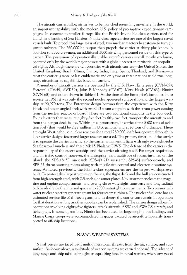
296 Military Technologies of the World
The aircraft carriers allow air strikes to be launched essentially anywhere in the world,an important capability with the modern U.S. policy of preemptive expeditionary cam-paigns. In contrast to smaller fl attops like the British Invincible-class carriers used forlaunch and landing of Sea Harriers, Nimitz-class supercarriers are one of the largest navalvessels built. To propel this large mass of steel, two nuclear reactors heat steam to turn gi-gantic turbines. The 260,000 hp output then propels the carrier at thirty-plus knots. Inaddition to 3300 crewmen, an additional 3000 air wing personnel reside on this type ofcarrier. The possession of operationally viable aircraft carriers is still mostly exclusive,operated only by the world’s major powers with a global interest in territorial or geopoliti-cal rights. Although there are ten countries with aircraft carriers—the United States, theUnited Kingdom, Brazil, China, France, India, Italy, Spain, Thailand, and Russia—inmost the carrier is more or less emblematic and only two or three nations wield true long-range aircraft strike capabilities based on carriers.
A number of aircraft carriers are operated by the U.S. Navy: Enterprise (CVN-65),Forrestal (CV-59, AVT-59), John F. Kennedy (CV-67), Kitty Hawk (CV-63), Nimitz(CVN-68), and others shown in Table 8.1. At the time of the Enterprise’s introduction toservice in 1961, it was only the second nuclear-powered surface ship and the largest war-ship at 90,970 tons. The Enterprise design borrows from the experience with the KittyHawk and has an angled deck with two C13 steam catapults with the steam power comingfrom the nuclear reactor onboard. There are two additional catapults in the bow deck.Four elevators that measure eighty-fi ve feet by fi fty-two feet transport the aircraft to andfrom the hangar deck below. Within its superstructure, it carries some 8500 tons of avia-tion fuel (that would be 2.72 million in U.S. gallons) and 2520 tons of ordnance. Thereare eight Westinghouse nuclear reactors for a total 280,000 shaft horsepower, although inlater carrier designs fewer and larger reactors are used. The primary function of the carrieris to operate the carrier air wing, so the carrier armament is light with only two eight-tubeSea Sparrow launchers and three Mk 15 Phalanx CIWS. The defense of the carrier is theresponsibility of the escort warships and the carrier air wing itself. For target acquisitionand air traffi c control, however, the Enterprise has a multitude of radars installed on theisland: the SPS-48 3D air-search, SPS-49 2D air-search, SPS-64 surface-search, andSPS-65 threat-warning radars along with missile fi re control and electronic warfare sys-tems. As noted previously, the Nimitz-class supercarriers are the largest warships everbuilt. To protect this large structure on the sea, the fl ight deck and the hull are constructedfrom high-strength steel, with 2.5-inch side armor plates. Kevlar armor encloses the maga-zine and engine compartments, and twenty-three watertight transverse and longitudinalbulkheads divide the internal space into 2000 watertight compartments. Two pressurized-water nuclear reactors generate steam for four steam turbines. The nuclear fuel core has anestimated service life of thirteen years, and in theory the carrier can remain in operationfor that duration as long as other supplies can be replenished. The carrier design allows foroperations involving eighty-fi ve fi ghters, attack aircraft, ASW and AWACS aircraft, andhelicopters. In some operations, Nimitz has been used for large amphibious landings, andMarine Corps troops were accommodated in spaces vacated by aircraft temporarily trans-ported to off-ship locations.
NAVAL WEAPON SYSTEMS
Naval vessels are faced with multidimensional threats, from the air, surface, and sub-surface. As shown above, a multitude of weapon systems are carried onboard. The advent oflong-range anti-ship missiles brought an equalizing force in naval warfare, where any vessel
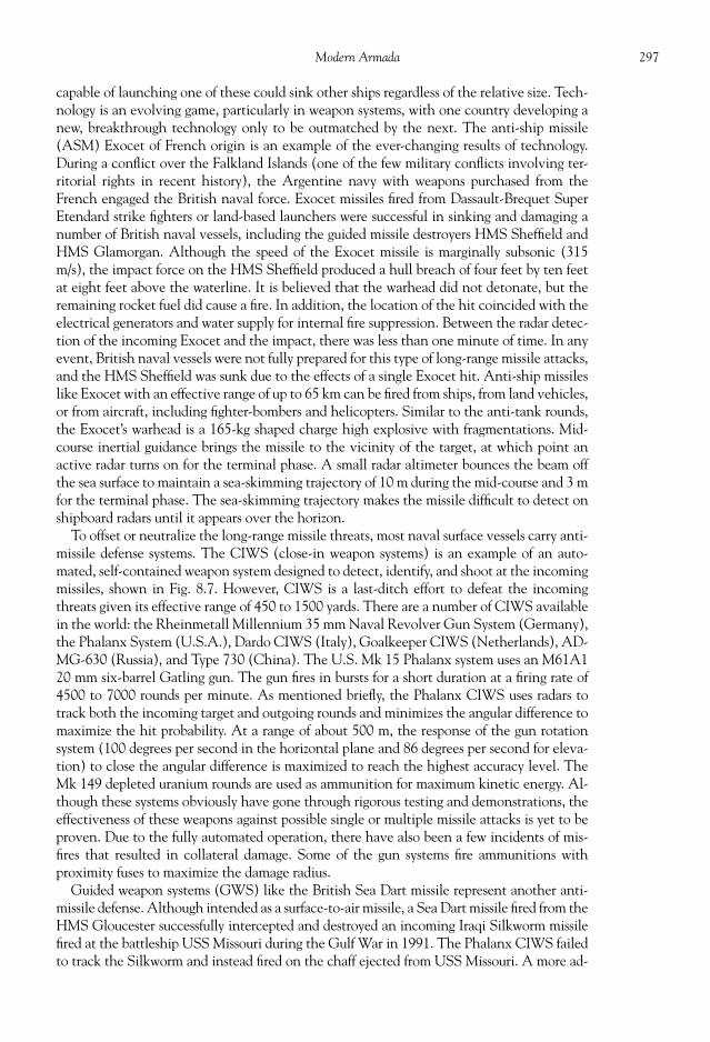
297Modern Armada
capable of launching one of these could sink other ships regardless of the relative size. Tech-nology is an evolving game, particularly in weapon systems, with one country developing anew, breakthrough technology only to be outmatched by the next. The anti-ship missile(ASM) Exocet of French origin is an example of the ever-changing results of technology.During a confl ict over the Falkland Islands (one of the few military confl icts involving ter-ritorial rights in recent history), the Argentine navy with weapons purchased from theFrench engaged the British naval force. Exocet missiles fi red from Dassault-Brequet SuperEtendard strike fi ghters or land-based launchers were successful in sinking and damaging anumber of British naval vessels, including the guided missile destroyers HMS Sheffi eld andHMS Glamorgan. Although the speed of the Exocet missile is marginally subsonic (315m/s), the impact force on the HMS Sheffi eld produced a hull breach of four feet by ten feetat eight feet above the waterline. It is believed that the warhead did not detonate, but theremaining rocket fuel did cause a fi re. In addition, the location of the hit coincided with theelectrical generators and water supply for internal fi re suppression. Between the radar detec-tion of the incoming Exocet and the impact, there was less than one minute of time. In anyevent, British naval vessels were not fully prepared for this type of long-range missile attacks,and the HMS Sheffi eld was sunk due to the effects of a single Exocet hit. Anti-ship missileslike Exocet with an effective range of up to 65 km can be fi red from ships, from land vehicles,or from aircraft, including fi ghter-bombers and helicopters. Similar to the anti-tank rounds,the Exocet’s warhead is a 165-kg shaped charge high explosive with fragmentations. Mid-course inertial guidance brings the missile to the vicinity of the target, at which point anactive radar turns on for the terminal phase. A small radar altimeter bounces the beam offthe sea surface to maintain a sea-skimming trajectory of 10 m during the mid-course and 3 mfor the terminal phase. The sea-skimming trajectory makes the missile diffi cult to detect onshipboard radars until it appears over the horizon.
To offset or neutralize the long-range missile threats, most naval surface vessels carry anti-missile defense systems. The CIWS (close-in weapon systems) is an example of an auto-mated, self-contained weapon system designed to detect, identify, and shoot at the incomingmissiles, shown in Fig. 8.7. However, CIWS is a last-ditch effort to defeat the incomingthreats given its effective range of 450 to 1500 yards. There are a number of CIWS availablein the world: the Rheinmetall Millennium 35 mm Naval Revolver Gun System (Germany),the Phalanx System (U.S.A.), Dardo CIWS (Italy), Goalkeeper CIWS (Netherlands), AD-MG-630 (Russia), and Type 730 (China). The U.S. Mk 15 Phalanx system uses an M61A120 mm six-barrel Gatling gun. The gun fi res in bursts for a short duration at a fi ring rate of4500 to 7000 rounds per minute. As mentioned briefl y, the Phalanx CIWS uses radars totrack both the incoming target and outgoing rounds and minimizes the angular difference tomaximize the hit probability. At a range of about 500 m, the response of the gun rotationsystem (100 degrees per second in the horizontal plane and 86 degrees per second for eleva-tion) to close the angular difference is maximized to reach the highest accuracy level. TheMk 149 depleted uranium rounds are used as ammunition for maximum kinetic energy. Al-though these systems obviously have gone through rigorous testing and demonstrations, theeffectiveness of these weapons against possible single or multiple missile attacks is yet to beproven. Due to the fully automated operation, there have also been a few incidents of mis-fi res that resulted in collateral damage. Some of the gun systems fi re ammunitions withproximity fuses to maximize the damage radius.
Guided weapon systems (GWS) like the British Sea Dart missile represent another anti-missile defense. Although intended as a surface-to-air missile, a Sea Dart missile fi red from theHMS Gloucester successfully intercepted and destroyed an incoming Iraqi Silkworm missilefi red at the battleship USS Missouri during the Gulf War in 1991. The Phalanx CIWS failedto track the Silkworm and instead fi red on the chaff ejected from USS Missouri. A more ad-
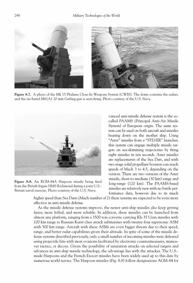
298 Military Technologies of the World
vanced anti-missile defense system is the so-called PAAMS (Principal Anti-Air MissileSystem) of European origin. The same sys-tem can be used on both aircraft and missilesbearing down on the mother ship. Using“Aster” missiles from a “SYLVER” launcher,this system can engage multiple missile tar-gets on sea-skimming trajectories by fi ringeight missiles in ten seconds. Aster missilesare replacements of the Sea Dart, and withtwo-stage solid propellant boosters can reachspeeds of Mach 3 to 4.5, depending on theversion. There are two versions of the Astermissile, short-to-medium (30 km) range andlong-range (120 km). The PAAMS-basedmissiles are relatively new with no battle per-formance data, however due to its much
higher speed than Sea Darts (Mach number of 2) these systems are expected to be even moreeffective in anti-missile defense.
As the missile defense systems improve, the newer anti-ship missiles also keep gettingfaster, more lethal, and more reliable. In addition, these missiles can be launched fromalmost any platform, ranging from a 3500-ton corvette carrying Kh-35 Uran missiles with100 km range to Russian Kurst-class attack submarines with twenty-four supersonic ASMwith 500 km range. Aircraft with these ASMs are even bigger threats due to their speed,range, and better radar capabilities given their altitude. In spite of some of the missile de-fense systems described previously, only a small number of incoming missiles were defeatedusing projectile hits with most evasions facilitated by electronic countermeasures, maneu-ver tactics, or decoys. Given the possibility of saturation attacks on selected targets andadvances in anti-ship missile technology, the advantage lies with the attacker. The U.S.-made Harpoons and the French Exocet missiles have been widely used up to this date bynumerous world navies. The Harpoon missiles (Fig. 8.8) follow designations AGM-84 for
Figure 8.7. A photo of the Mk 15 Phalanx Close-In Weapons System (CWIS). The dome contains the radars,and the six-barrel M61A1 20 mm Gatling gun is seen fi ring. Photo courtesy of the U.S. Navy.
Figure 8.8. An RGM-84A Harpoon missile being fi redfrom the British frigate HMS Richmond during a joint U.S.-Britain naval exercise. Photo courtesy of the U.S. Navy.

299Modern Armada
air-launched, RGM-84 for ship-launched, and UGM-84 for submarine-launched versions.The latter two versions come with a solid rocket booster and an encapsulated container(for UGM-84) to launch the missile from low-speed platforms. Once launched, the turbo-jet engine takes over and propels the missile to a high subsonic speed of 530 mph. TheAGM-84 can be launched from a number of aircraft, including the F/A-18, F-16, or P-3Orion (a propeller-driven maritime patrol aircraft). Exocets also can be launched fromdifferent vessels and use the designations AM39 (air launch), MM38 (surface launch),and SM39 (submarine launch). The solid rocket motor propels the missile to a speed ofover 700 mph (subsonic).
In contrast, the Russian ASMs tend to have supersonic capabilities, posing a seriouschallenge for the missile defense systems. The Russian Kh-31 “Zvezda” anti-ship missile,for example, also uses air-breathing engine like the Harpoon missiles, except this one is anadvanced ramjet engine with a speed of Mach 2. More recent additions to the Russianarsenal include the P-270 “Moskit,” or SS-N-22 “Sunburn” by NATO designations, anti-ship cruise missile. Introduced in 1993 and used by Russia and China, the missile comes inat a length of 9.75 meters and a diameter of over 1.2 meters (4 feet). It carries a warheadof 320 kg of high explosive shaped charge or a 200 kiloton nuclear warhead, at a speed ofMach 2.6 to 3, or close to 1000 m/s. Again a ramjet is used once the rocket achieves super-sonic cruise speed from the launch solid rocket booster. With an estimated range of 120km and mid-course autopilot and terminal active radar guidance, it is a “fi re-and-forget”type of weapon.
The classic depth charges were used against submarines during World War II. With in-creased torpedo ranges, corresponding increase in the range of anti-submarine warfare(ASW) weapons is needed. The ASROC (anti-submarine rocket) is an example of the mainASW weapon. By using rocket boosters to the vicinity of the submarine the payload torpedocan engage the target at much longer range and also with lower possibility of acoustical de-tection. To carry the torpedoes, these systems tend to be large with the Russian SS-N-14having a length of over 7 meters. The U.S. ASROC stands just over 4 meters and consists ofthe Mk 46 sonar-guided torpedo with a solid rocket booster. The torpedo carries a 95-lbPBXN-103 high explosive or a W44 1 kton nuclear warhead. With larger and stronger sub-marine hulls, nuclear warhead may be the only effective weapon for high probability kills inthe future, in spite of its environmental and political ramifi cations. The Mk 46 can also bedeployed directly from helicopters, aircraft, and surface ships. To increase the speed andrange, a chemical fuel motor is used in place of electric drive. A liquid monopropellant pro-duces energy that is converted to mechanical torque to drive the propellers. The Mk 48 is a“heavyweight” torpedo with a total weight of 3450 lb out of which 650 lb goes to the war-head. A 500-hp gas-piston engine drives the torpedo, again powered by an “Otto II” liquidmonopropellant consisting of nitrogen ester and hydroxylamine perchlorate. The Mk 48 canbe launched as a self-guided or wire-guided torpedo with active and passive sonar for termi-nal homing. In its ninteen-plus-foot frame, it carries the sonar and homing devices, controlelectronics of gyro and computer, warhead, fuel tank and motor, and steering surfaces. Oncelaunched, the torpedo “clears” the launch area and cruises to the preselected “enable” point.From that point, the torpedo independently searches for the target, and once locked on ac-celerates to the target. The Mk 50 is the upgrade of the Mk 46 lightweight torpedo andcontains larger amount of warhead but more important much improved sonar and guidancesystem. The active/passive sonar generates and tracks multiple outgoing and incoming sig-nals and can engage targets at twice the distance of its precursor. The ability to move fasterand at a greater depth allows for a better operating envelope for this torpedo.
An array of cannon-type weapons can also be found on warships. The close-in weaponssystems (CIWS) mentioned previously constitutes the last line of defense against missile

300 Military Technologies of the World
and to some extent aircraft attacks. The Mk15 Phalanx system integrates radar units withthe hydraulically rotated Vulcan cannon that fi res 20 mm rounds at a rate up to 4500rounds per minute. The Mk 16 Weapons Group consists of a modifi ed M61 Vulcan six-barrel Gatling-type cannon and J-band pulse-Doppler fi re control radar. The entire systemis integrated and mounts on naval vessels without any structural modifi cations. The Mk16’s onboard radar classifi es threats communicated from the search radar and computes thetracking azimuth. The J-band fi re control radar tracks both the target and outgoing bulletstream, and the computer attempts to arrive at a fi ring solution typically using a closed-loop algorithm to minimize the difference between the radar line-of-sight to the target andthe projectile trajectory. Tungsten penetrator ammunition is preferred over the earlier Mk149 depleted uranium rounds due to reduced cost and handling requirements.
The “Emerlec” mount with two Oerlikon 30 mm automatic cannons is used for anti-aircraft fi re. The gunner sits between the two cannons to manually direct the fi ring. TheMk 75 76 mm mount is a licensed version of the Italian OTO Melara Compact gun and isused on small naval warships. The Mk 75 unit is designed for both anti-aircraft and anti-ship use, with an effective range of 18,991 feet (5788 meters) for anti-air and 17,391 yards(15,902 meters) for anti-ship operations. The fi re control is via a Mk 92 track-and-scangunfi re control system and directs fi re at a rate up to eighty-fi ve rounds per minute. TheMk 42 and Mk 45 systems are of yet higher caliber at 5 inches or 127 mm and require acrew of ten to twelve to operate. These guns can fi re both conventional rounds for a rangeof 14 to 21 km and rocket-assisted projectiles (RAP) to a range of 29 km. These guns areused on frigates, destroyers, or cruisers.
The use of this complex array of weaponry in highly fl uid battle situations involvinghundreds of friendly and hostile objects can be facilitated with the aid of advanced battlemanagement systems like the U.S. Navy’s Aegis. An effective use of the weapons is byidentifying the target threat levels and coordinating the weapons deployment from theavailable pool in the battle group. The Aegis system is typically built into Ticonderoga-classguided missile cruisers for the U.S. Navy, although other navies use destroyers for Aegisplatforms. The SPY-1 synthetic aperture radars are the foundation of the Aegis system. EachSPY-1 radar has a coverage of 100 degrees. By modifying the outgoing radar beams in the4400 individual transmitters in the radar array, SPY-1 can track hundreds of targets withone-second update time intervals while scanning the sky for additional targets. The SPY-1radar can not only see the aircraft but also the surface-to-air missiles heading toward themand, after the hit, the trajectories of the debris and ejection seats. For over-the-horizon intel-ligence, airborne early warning radars onboard the E-2C Hawkeye feed long-range data toAegis. During Operation Desert Storm, the early warning aircraft like the Hawkeye and theAir Force AWACS could send tracking data for aircraft fl ying in Greece, some 900 milesfrom the U.S. carrier strike groups in the Red Sea. The data from sonar is also integrated intothe Aegis data system. The combined air-surface-submarine battlefi eld data are displayed infour large display screens in the combat information center (CIC) room on the cruiser (seeFig. 8.9). Other information such as the status of the weapons and air, surface, and subma-rine situations is displayed through thirty-plus smaller monitors. The cruiser commandermay assign weapons manually based on the displayed target information, or he can switchthe Aegis to automatic targeting, in which case the Aegis will generate target priority andweapons assignment listings and communicate this information through data links to as-signed ships in the strike group. In addition, the cruiser’s own SM-2 Standard Missile systemmay be deployed. All of this sequencing is made by the Mk 99 fi re control system and thecommand and decision computer program integrated with the Aegis system. There are cur-rently more than 100 Aegis-installed naval vessels in the world, including those in theUnited States, Japan, the Republic of Korea, Norway, Spain, and Australia.

301Modern Armada
SONAR
For ASW and submarine operations, sonar (sound navigation and ranging) is the singlemost important sensor for detection, tracking, navigation, and to some extent communi-cations. Sonar makes use of the high speed of sound in water and the low dissipation ofsound waves in water due to its relative incompressibility. Simply put, sound waves travelfast and far in water. But ocean water is not homogeneous, and the water pressure, tem-perature, and salinity affect the speed of sound. The speed of sound (in feet per second)can be empirically calculated by
Speed of sound in water = 4388 + 11.25 × water temperature in °F + 0.0182 × depth(in feet) + salinity (in parts per thousand)
Salinity is the amount of salt in the sea water by mass, and ranges from 32 to 37 partsper thousand in the oceans. The temperature and pressure both increase the movementsof the water molecules, and therefore increases in depth raise the pressure and also thespeed of sound. So at a depth of 3000 feet, with a water temperature of 10o F and salinityof 35 parts per thousand, the speed of sound is 4927 feet per second or 1502 meters persecond. By comparison, in air at the same temperature the speed of sound is approximately334 meters per second. The depth gives a large but predictable change in the speed ofsound, while the salinity and temperature profi les can vary.
Since all waves become bent or refracted by any change in the wave speed, this causesvariability in the paths of sound propagation that can lead to errors in locating the source
Figure 8.9. Multiple displays of the command and battle information system in the combat center of an air-craft carrier. Photo courtesy of the U.S. Department of Defense.

302 Military Technologies of the World
of the refl ected sounds. For example, objects appear to be at a shallower depth when sub-merged in water because the light rays become refracted when passing from the water toair. For targeting purposes, this needs to be corrected as much as possible. A typical tem-perature profi le in the ocean involves fi rst the surface seasonal layer, with its high vari-ability as a function of the time of the day and season due to its proximity to the surface(100 to 250 meter depth). The water temperature drops with increasing depth to a depthof about 1200 meters, with that range being called “permanent thermocline.” Beyond thisdepth, the water temperature change becomes minimal at stays at about 34o F. In thatrange of depth, the increase in the speed of sound is primarily due to depth or the pressureeffect. Thus, the profi le of the speed of sound as a function of the depth looks somethinglike what is shown in Fig. 8.10. As noted previously, the effect of this change in the speedof sound is to refract any sound waves traveling across this profi le. A sound wave emittedfrom a surface source, like a destroyer, would initially be pointed downward but due to thisprofi le will slowly be bent upward to fi nally reach back to the surface. The surface refl ectsthe sound wave back, and this sequence can go on many cycles until the sound energy islost through dissipation. This actually provides a tunneling effect where the sound canpropagate to much longer distances as opposed to a simple cylindrical spreading. Duringcircular spreading, the sound energy will be reduced by the square of the radius. In fact, theabove tunneling effect refracts and focuses the emitted sound wave to a small region backon the surface called a convergence zone. So a sonar signal emitted by a source on theforward part of the destroyer, if refracted normally, will converge back on the surface atsome distance (twenty to thirty nautical miles) ahead of the destroyer. In theory, anythingin the path of this sound wave traversing some twenty to thirty nautical miles can be heard
by monitoring the refl ected sounds. With modernsonar sensors, refl ections from up to the third conver-gence zones can be detected with reasonable signal tonoise ratio. If the conditions are right, another chan-neling effect can occur where the sound waves bounceback and forth between two boundaries of the soundspeed variations with small losses at these interfaces.This “deep sound channeling” allows the sound to betransmitted hundreds of miles.
The dissipation of the sound energy is highly de-pendent on the frequency of the sound. For example,the loss in sound energy is four times greater at 20kHz than at 10 kHz. So the lower the sound frequency,the larger its propagation distance will be. However,for accurate tracking and frequency profi ling of thesound signal, higher frequency is needed. Thus, thesonar frequency is optimized depending on the pur-pose. Active scanning sonar uses audible frequenciesfrom 5 to 20 kHz with pulses called “pings” being sent12.5 to 700 milliseconds apart, while torpedo sonaruses higher frequencies of 20 to 35 kHz due to theirshort-range, high-accuracy requirements.
The sonar modules used in surface ships involvean array of a large number of transducers (essentiallyspeakers/microphones to generate pings and thenmonitor the returning sounds) in circular or rectan-gular grids. One can use either passive or active, with
Figure 8.10. A sketch of the speed of soundvariation as a function of the ocean depth.

303Modern Armada
the latter sending sound beams and listening to the refl ected sounds. For a submarine inoperation, passive sonar can pick up the noise generated by the formation and collapse ofbubbles as the propellers rotate in water, a process called cavitation. Other vibration orrotation of internal machinery also produces noise, as does unguarded noise by the crew.These sounds tend to be of low frequency and thus can travel long distances. Finally, thesound generated by active sonar of course can be used against the user by giving away theirpresence and location. Thus, good submariners tend to use active sonar sparingly. Thetransducers in active sonar send directionally resolved sound beams and monitor the re-turn signals in the same direction to obtain the angular position of the sound refl ectingsources. As noted previously, the sound wave paths are calculated based on the best avail-able data on ocean conditions and along with the time it takes for the refl ected sound totraverse the path are used to determine the distance to the target. Interferences with sonaroperation occur due to the noise generated by the movement of the ship employing thesonar, marine animals, extraneous merchant and military vessels, weather conditions, andunderwater volcanic and seismic activities. In fact, large whales tend to generate sonarrefl ection quite similar to submarines, and sophisticated fi ltering and software program-ming is needed to identify true targets against all of the background interference.
There are many different sonar systems used for specifi c purposes, but all essentiallyoperate under the same principle of audio signal generation/reception, amplifi cation, anal-ysis, and display. The audio signals are directly heard via a speaker and also the analyzeddata are displayed in a manner similar to radars. For example, the sonar system designatedas AN/SQS-53 is used on U.S. Navy surface ships in a bow dome (see Fig. 8.11). The sig-nals are digitally interfaced with shipboard Mk 116 ASW weapons control system. Thesonar has digital compensation algorithms (i.e., computer programs) for correction of thecalibration and alignment errors. This sonar has both active (3 to 4 kHz) and passive (1.5kHz) modes, with the passive mode again using lower frequency to compensate for noiseand losses.
There are of course other ways that sonar is deployed. The “dipping” sonar like theAQS-18 can be lowered and towed by the Navy’s Sea King ASW helicopter (see Fig. 8.12).The AQS-18 module includes bathythermal (temperature as a function of the depth) sen-sor, passive sonar, and active sonar for target range and bearing. Due to short-range ap-plications and the need to acquire accurate target location, dipping sonar uses highfrequencies—9.23, 10, or 10.77 kHz. The sensor module weighs 30 lbs and the cable lengthis typically over 1000 feet. The submarine sonar follows the BSY designations for theU.S. Navy. The AN/BYS-1, for example, is an integrated sonar-based combat system usedon Los Angeles–class submarines. It performs an array of functions, including detectionand tracking of targets, controlling the settings for weapons against the targets, and pilot-ing and navigation functions. A number of sonars used in the BYS-1 system allow theperformance of those functions: medium-frequency spherical array sonar mounted in thebow, high frequency sonar in the sail section of the submarine, and two towed arrays ofpassive sonar. Towing of sonar arrays is also used on surface ships, like the SQR-19 TAC-TAS. The towed module includes a vibration isolator, heading/depth/temperature sensors,and sixteen individual sonars (eight at very low frequency, four at low frequency, two atmedium frequency, and two at high frequency). The Sound Surveillance Systems (SOSUS)are near-permanent sonar units placed on the seafl oor at logistic locations. The SOSUSare passive sonar arrays to detect submarines and to communicate the data so active track-ing of these submarines can be pursued by surface or submarine vessels. In addition,there are sonobuoys—small fl oating modules with various lifetimes—for ocean data ac-quisitions, active/passive sonar, acoustic communication links, and electronic counter-measures.

304 Military Technologies of the World
The deployment for the sonar and other sensors in anti-submarine warfare follows asystematic order. First, a sub-hunter aircraft like the S-3A Viking will dispense cylindricalsonobuoys, which as noted are relatively simple passive listening devices sometimes called“Jezebels” in a grid array with a spacing of several miles. The underwater microphones inthe sonobuoys transmit acoustic signals to the operator on the Viking aircraft. The ampli-tude and timing of any submarine-derived noise are analyzed by the computer to output anapproximate location and a boundary for a high probability fi nd for the target submarine.
Figure 8.11. The sonar dome protrudes from the bottom of the hull from Arleigh Burke–class Aegis-equipped guided missile destroyer USS Shoup. Photo courtesy of the U.S. Department of Defense.

305Modern Armada
The next action involves targeting this perimeter by placing active pinging sonobuoys.The refl ected sound signals are again analyzed to generate yet smaller perimeter for a highprobability of locating the submarine, and pinging sonobuoys are moved yet closer. Thus,this sequence slowly tightens the noose around the target until an area of about a 100-meter radius is isolated with near certainty of containing the submarine. During the fi nalstage, a magnetic anomaly detector (MAD) that detects minute perturbations of the earthmagnetic fi eld due to the presence of a large metal objects, like a submarine, may also bedeployed. Within this radius, any of the anti-submarine weapons have a high probabilityof success in engaging and destroying the submarine.
CARRIER STRIKE GROUP
The signifi cance of carrier-based air strike capability became evident during World WarII in the Pacifi c theater. In fact, it was Japan who launched an unprecedented, long-rangepreemptive strike using carrier-based bombers and fi ghters on Pearl Harbor. With an his-torical irony, the U.S. Navy carriers were elsewhere during the Pearl Harbor attack, andonly the battleships and cruiser fl eet was damaged or completely disabled. Later in the war,the table turned, and it was the U.S. Navy who used carrier-based aircraft to demolishJapanese naval prowess. The naval supremacy enabled large landing forces to be engagedin a chain of costly but victorious battles in the Pacifi c islands, which in turn secured land-ing strips to allow massive bombing of the Japanese mainland.
Figure 8.12. The U.S. Navy SH-3H Sea King helicopter deploying the AQS-13 dipping sonar. Photo cour-tesy of the U.S. Department of Defense.

306 Military Technologies of the World
If naval supremacy allowed the expansion and protection of national, mostly imperialis-tic interests during the 1800 to 1900 time period, modern warfare dictates that air su-premacy be secured fi rst prior to engaging in land battles. The reasons are obvious, groundtroops and vehicles including heavily armored tanks are vulnerable to attacks from the air.Also, battlefi eld intelligence is best obtained from a high altitude. These factors allow theside who has established air supremacy to operate with impunity on the ground. Particu-larly with stealth fi ghter-bombers, night vision–enabled helicopters, and precision muni-tions, key command-and-control sites, radar-based SAMs, and other strategic targets canbe surgically removed to disable the other side from the air. The carrier-based air strikecapabilities extend the range of an air campaign to the entire globe. With the current U.S.foreign policy of apparently negating external threats to national security in faraway loca-tions, the carriers are the centerpiece of these expeditionary missions by providing a mobileplatform to launch air strikes in any part of international waters. The many components(e.g., destroyers, attack submarines, guided missile cruisers, early-warning aircraft, andfi ghter-bombers) make a carrier strike group a complete and fl exible force. A large numberof cruise missiles and aircraft-launched munitions can knock out ground targets. Attacksubmarines and ASW destroyers, guided by the information supplied from airborne andsatellite-based early-warning systems, establish a large-radius perimeter that would be un-wise for the opposing navy to cross. The combined air and naval fi repower contained in thecarrier-based group mutually enhance the integrity and operational freedom of both com-ponents. Finally, a nuclear-powered carrier can operate indefi nitely, and carrier operationis inherently local, making its presence a lasting impact in the region, for better or worse.
As noted previously, the aircraft carrier itself can be as long as 1000 feet with a displace-ment of close to 100,000 tons. Along with a crew of several thousand, it is a gigantic warmachine costing several billion dollars to build and maintain. The utility of such an in-vestment has been described in previous paragraphs, but the cost and manpower requiredto maintain a carrier strike group, with all the attendant surface and submarine vessels andthe carrier air wing and aircraft, limit the possession of viable carrier strike capability toonly a few nations. The United States is by far the nation with the mightiest carrier fl eetwith current twelve carrier strike groups, and therefore it bears the economic, geopolitical,and military burden of wielding this force. Carriers designed to transport VSTOL (verticalshort take-off and landing) aircraft, however, are quite commonplace. Defl ected jets likethe Harrier can take off and land vertically, or even hover or fl y backwards. Such opera-tions expend an exorbitant amount of fuel that could otherwise extend the mission radiusso that take-off ramps are used to minimize fuel usage. Without the complex catapult andarrest-wire landing systems, such carriers can be made much smaller than fi xed-wing air-craft carriers.
A carrier strike group consists of the carrier, usually a 100,000-ton supercarrier for theU.S. Navy; the carrier air wing with eighty-plus aircraft including fi ghter-bombers, earlywarning, anti-submarine warfare, and electronic warfare aircraft; one or two guided mis-sile cruisers; about seven frigates and destroyers; and one or two attack submarines. Thisgroup of vessels moves in the ocean in a formation that may cover some 30,000 squaremiles and forms triple layers of protection for the carrier. F/A-18 Hornets with externalfuel tanks may patrol the air space with an outer radius of 200-plus miles to prevent launch-ing of long-range anti-ship missiles. The middle layer of defense is provided by the guidedmissile cruisers and destroyers. Any “leakers” or projectiles that somehow manage to get towithin twenty miles of the carrier would be met by short-range anti-missile missiles andCIWS described above. A carrier usually has four CIWS at four corners of the ship, alongwith missile launchers on both sides. In addition, the sub-surface threats are deterred bythe attack submarine prowling underneath the carrier and an assortment of sonar-derived

307Modern Armada
anti-submarine warfare weapons from surface ships and aircraft. The operating sphere ofthe carrier strike group is even further extended by the early-warning aircraft that canmonitor a space hundreds of miles around the carrier.
In addition to its apparent size, the carrier is distinguishable by the commanding bridgeset aside to maximize the surface for fl ight deck. The dimensions of the fl ight deck and thecarrier determine the number and type of aircraft that can be launched from the carrier.American nuclear-powered Nimitz-class supercarriers use conventional take-off and land-ing aircraft like the F-14 Tomcat and F/A-18 Hornet, with the aid of catapults and arrestwires, and can operate with eighty-fi ve fi xed-wing aircraft plus about fi ve helicopters. Inthese carriers, the fl ight deck is angled to maximize the length and also to secure space forstaging the aircraft for coordinated launch. At the other end of the spectrum, the BritishInvincible-class carrier has a displacement and length of 20,000 tons and 677 feet, andoperates with less than ten STOVL (short take-off and vertical landing) aircraft like theBAE FA2 Sea Harrier or the ultramodern F-35s to enter service in the near future. Themulti-decked structure underneath the fl ight deck holds the hangar space, engine room,and other compartments as shown in Fig. 8.13. The space directly below the fl ight deck ispartitioned with the command operations, catapult equipment, air squadron room, andmaintenance shops being located in the gallery (03) deck. A large space is reserved for themain hangar, where most of the aircraft are protected during down times. Some need to bealways parked on the fl ight deck, because the hangar space is not large enough to hold allof the eighty-fi ve aircraft on a Nimitz. The hangar deck alone is 684 feet (208.5 meters)long, 108 feet (33 meters) wide, and 25 feet (7.6 meters) high in Nimitz-class carriers.Armored sliding doors separate the hangar into three sections to isolate any damage. Ele-vators spaced along the length of the deck (two aft and two in the mid- and forward sec-tions) quickly transport the aircraft from the hangar to the fl ight deck, two fully loadedaircraft at a time per elevator. Fueling stations are usually adjacent to the hangar deck.
Figure 8.13. A sketch of the Nimitz-class aircraft carrier confi guration.

308 Military Technologies of the World
The gallery, hangar, and second decks are located above the waterline, with the third andfourth decks and the large engine compartment lying below. All the decks below the wa-terline are of double-sided hull design with torpedo protection.
Take off and landing on the deck is facilitated by catapults and arrest wires, as shown inFig. 8.14. The catapult on Nimitz-class carriers is a large, steam-powered double pistonwith the superheated steam coming from the nuclear reactor. The pressure charge in thesteam piston is adjusted precisely to match the aircraft launch weight, the wind magnitude
Figure 8.14. The catapults and arrest wire locations on the Nimitz-class carrier USS Ronald Reagan(CVN-76). Photo courtesy of the U.S. Department of Defense.

309Modern Armada
and direction, the carrier speed, and the air density and humidity. The idea is to generatethe take-off speed with both the catapult force and the full-throttle thrust of the aircraftengines without running the usual take-off distance to achieve this speed. The aircraft willbe launched into the wind to maximize the relative velocity, since the lift force needed toget the aircraft airborne depends on the square of this relative air velocity. In fact, the liftforce can be calculated by
(Lift Force) = (Lift Coeffi cient) × (Wing-body area) × 1/2 × (density) ×(relative air velocity)2
The lift coeffi cient is characteristic of the wing-body design, angle of attack (the pitchangle of the wing-body with respect to the incoming air velocity), and the fl ap confi gura-tion, which is fully extended to maximize lift. Nothing would be worse than failing to liftthe aircraft off the fl ight deck. The lift coeffi cient and the wing body area are of coursefi xed parameters for a given aircraft. The air density affects the lift force, with larger den-sity generating more lift. Thus, high temperature and low barometric pressure would bethe worst atmospheric condition for launching the aircraft because the defi ciency in thedensity has to be made up by increasing the aircraft launch speed. The relative air velocitygenerated is of course the aircraft speed attained plus the wind speed coming over theaircraft.
During ground-based take-off, the aircraft will start from zero speed and gradually applythe throttle to increase engine power. The aircraft accelerates while rolling on the ground,and when the take-off speed is attained the pilot would pull the control stick up to in-crease the pitch angle and get the aircraft off the ground. This process obviously takes timeand distance. F-16s, for example, have a minimum take-off distance of 1500 feet (457meters) at typical take-off weight, and for the F-18 the ground take-off would require anairstrip distance of 1700 feet (518 meters). There is clearly no such room on even the larg-est carriers, plus one needs the space for lining up other aircraft, equipment, and personneland a margin of error. The catapult therefore adds to the forward acceleration of the air-craft to reach the take-off speed much faster. The catapults are about 300 feet long andtypically less than half the deck length is used for the take-offs.
An operation involving aircraft launched from a carrier begins with a rather mundanetask of hundreds of deck crew walking down the deck to fi nd and eliminate any loose de-bris that could possibly be ingested by the aircraft engine and damage it. The aircraft areby this time positioned on the deck so they can taxi to the assigned catapult in line. Oncethe signals to start the aircraft engine are given, the noise level on the deck becomes ex-cessive and communications between the crew are made via a set of hand signals. Theforward nose gear of the aircraft is connected to the catapult via a fi xture called the “shut-tle,” which locks the nose tow point to the catapult motion. Prior to the launch, the air-craft will be held in check by a holdback mechanism while the pilot brings the engine tofull throttle. Once a good hookup between the aircraft and the catapult is verifi ed by sev-eral crewmen, a signal is given to the pilot for “brakes off, full power,” again in hand signals.A jet blast defl ector (JBD) is raised behind the aircraft to direct the full blast of the hot,supersonic exhausts upward away from any nearby personnel or equipment. A quick checkof the aircraft control surfaces are made by the pilot by moving the control stick forward,back, right, and left while troubleshooter crews check for any anomalies. Once the“thumbs-up” sign is raised, the aircraft is good to go, and a button on the deck is pressed tosignal to the catapult controller below the deck to fi re the catapult. At launch, the hold-back mechanism is disengaged by breaking in two halves and the high pressure piston isreleased. The aircraft rides the catapult while fully blasting its engines with afterburners to

310 Military Technologies of the World
maximize the thrust. The acceleration is ofcourse doubled by the dual actions, and thepilot would experience severe G forces witha speed of 150 knots being reached in twoseconds over a 300-foot distance. The Gforce, or the acceleration, is about fourtimes the earth’s gravity during the launch.To achieve this rapid increase in speed, therequired catapult power is about 30 MW,although some of the acceleration comesfrom the aircraft engines operating at fullblast with afterburners. There is usually afl are-up at the end of the fl ight deck to in-crease the aircraft angle of attack as it attainsits take-off speed. This intricately coordi-nated sequence is repeated until all of therequired aircraft are launched.
If the launch sequence seems like a highly dynamic event, the landing is by pilots’ ac-count the most diffi cult and stressful part of the mission, more so than being fi red on byanti-aircraft batteries according to some accounts. The photograph of the carrier deck inFig. 8.16 may give an idea. There certainly will not be any crew in the landing paths, butthere could very well be aircraft and personnel to both sides of the landing zone as shownin the photograph. The pilot needs to guide the aircraft to what must appear as a tiny spoton the sea and the get it down onto the carrier. It of course looks much smaller from theapproach distance. Plus there is the undulating motion of the carrier due to the wave mo-tion, not to mention the aircraft motion itself due to wind effects. On top of it all, somelandings must go on at night or in inclement weather conditions. The aircraft take off inthe forward direction, but approach the carrier from the rear for landing. The landing ofthe aircraft on the carrier deck is assisted by arresting wires, typically four of them in se-quence separated by about forty feet, with the number 1 arresting wire at the rearmostposition on the carrier deck. Carrier-based aircraft all have a “tailhook” at the rear underside
Figure 8.15. The F/A-18 Hornet in fl ight with the tailhook extended (left). The F/A-18C Hornet during anattempted landing (right) on the Nimitz-class carrier USS John C. Stennis (CVN-74). The tailhook failed tocatch any of the arresting wires, in which case the pilot must apply full throttle to get the aircraft back in the airfor a repeat try. Notice the sparks fl ying when the tailhook drags along the fl ight deck. Photo courtesy of the U.S.Navy.
Figure 8.16. A view of the carrier deck from the rear, whichis the landing side. Photo courtesy of the U.S. Navy.
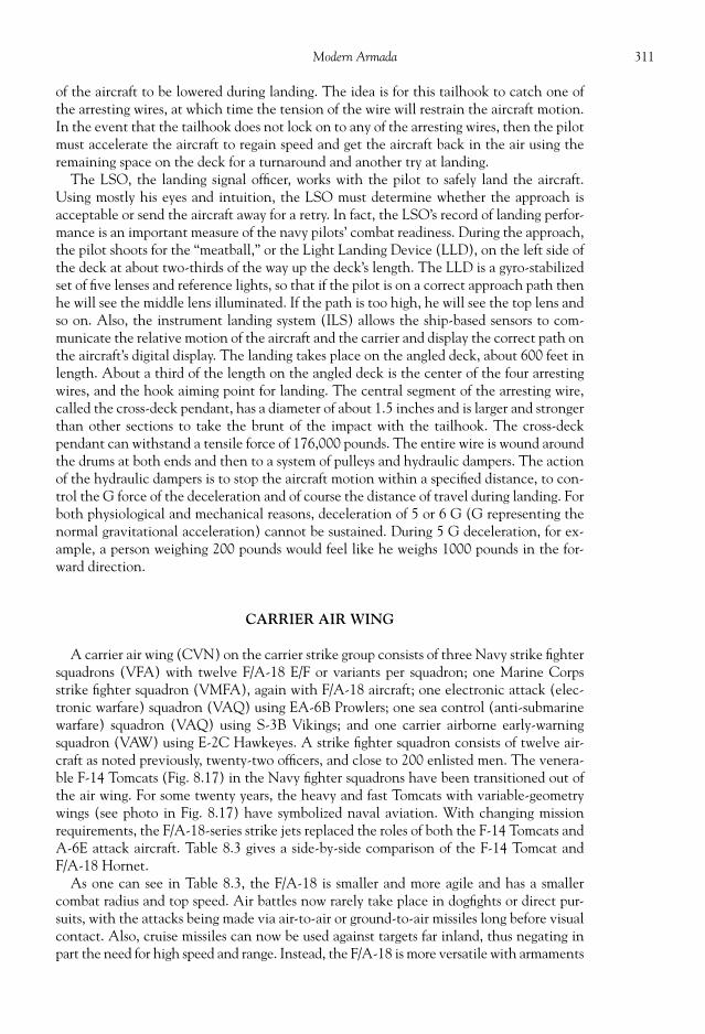
311Modern Armada
of the aircraft to be lowered during landing. The idea is for this tailhook to catch one ofthe arresting wires, at which time the tension of the wire will restrain the aircraft motion.In the event that the tailhook does not lock on to any of the arresting wires, then the pilotmust accelerate the aircraft to regain speed and get the aircraft back in the air using theremaining space on the deck for a turnaround and another try at landing.
The LSO, the landing signal offi cer, works with the pilot to safely land the aircraft.Using mostly his eyes and intuition, the LSO must determine whether the approach isacceptable or send the aircraft away for a retry. In fact, the LSO’s record of landing perfor-mance is an important measure of the navy pilots’ combat readiness. During the approach,the pilot shoots for the “meatball,” or the Light Landing Device (LLD), on the left side ofthe deck at about two-thirds of the way up the deck’s length. The LLD is a gyro-stabilizedset of fi ve lenses and reference lights, so that if the pilot is on a correct approach path thenhe will see the middle lens illuminated. If the path is too high, he will see the top lens andso on. Also, the instrument landing system (ILS) allows the ship-based sensors to com-municate the relative motion of the aircraft and the carrier and display the correct path onthe aircraft’s digital display. The landing takes place on the angled deck, about 600 feet inlength. About a third of the length on the angled deck is the center of the four arrestingwires, and the hook aiming point for landing. The central segment of the arresting wire,called the cross-deck pendant, has a diameter of about 1.5 inches and is larger and strongerthan other sections to take the brunt of the impact with the tailhook. The cross-deckpendant can withstand a tensile force of 176,000 pounds. The entire wire is wound aroundthe drums at both ends and then to a system of pulleys and hydraulic dampers. The actionof the hydraulic dampers is to stop the aircraft motion within a specifi ed distance, to con-trol the G force of the deceleration and of course the distance of travel during landing. Forboth physiological and mechanical reasons, deceleration of 5 or 6 G (G representing thenormal gravitational acceleration) cannot be sustained. During 5 G deceleration, for ex-ample, a person weighing 200 pounds would feel like he weighs 1000 pounds in the for-ward direction.
CARRIER AIR WING
A carrier air wing (CVN) on the carrier strike group consists of three Navy strike fi ghtersquadrons (VFA) with twelve F/A-18 E/F or variants per squadron; one Marine Corpsstrike fi ghter squadron (VMFA), again with F/A-18 aircraft; one electronic attack (elec-tronic warfare) squadron (VAQ) using EA-6B Prowlers; one sea control (anti-submarinewarfare) squadron (VAQ) using S-3B Vikings; and one carrier airborne early-warningsquadron (VAW) using E-2C Hawkeyes. A strike fi ghter squadron consists of twelve air-craft as noted previously, twenty-two offi cers, and close to 200 enlisted men. The venera-ble F-14 Tomcats (Fig. 8.17) in the Navy fi ghter squadrons have been transitioned out ofthe air wing. For some twenty years, the heavy and fast Tomcats with variable-geometrywings (see photo in Fig. 8.17) have symbolized naval aviation. With changing missionrequirements, the F/A-18-series strike jets replaced the roles of both the F-14 Tomcats andA-6E attack aircraft. Table 8.3 gives a side-by-side comparison of the F-14 Tomcat andF/A-18 Hornet.
As one can see in Table 8.3, the F/A-18 is smaller and more agile and has a smallercombat radius and top speed. Air battles now rarely take place in dogfi ghts or direct pur-suits, with the attacks being made via air-to-air or ground-to-air missiles long before visualcontact. Also, cruise missiles can now be used against targets far inland, thus negating inpart the need for high speed and range. Instead, the F/A-18 is more versatile with armaments

312 Military Technologies of the World
Figure 8.17. Photos of now-decommissioned F-14 Tomcat jet fi ghter.
Table 8.3. Comparison of F-14 Tomcat and F/A-18 Hornet Naval Strike Aircraft
F-14 Tomcat F/A-18 Hornet
Crew Pilot, radar intercept offi cer Pilot, weapons system offi cerLength 19.1 meters (62 ft 9 in) 17.1 meters (56 ft)Wingspan 19.5 meters (64 ft), spread 12.3 meters (40 ft), fi xed
11.6 meters (38 ft), retracted
Height 4.9 meters (16 ft) 4.7 meters (15 ft 4 in)Wing NACA 64A209.65, root NACA 65A005, root
NACA64A208.91, tip NACA65A003.5, tip54.5 m2 (565 ft2 ), wing
surface area38 m2 (400 ft2 ), wing
surface area
Empty Weight 19,838 kg (43,735 lb) 11,200 kg (24,700 lb)Maximum Take-Off
Weight33,720 kg (74,350 lb) 23,400 kg (51,500 lb)
Engine Two General ElectricF110-GE-400 afterburningturbofans
Two General ElectricF404-GE-402 afterburningturbofans
Thrust = 61,400 kN (13,810lbf) each
Thrust = 48,900 kN(11,000 lbf) each
Thrust with afterburning =124,700 kN (27,800 lbf)each
Thrust with afterburning =79,200 kN (17,750 lbf)each
Maximum Speed Mach 2.34 (1544 mph) Mach 1.8 (1190 mph)Combat Radius 926 km (575 miles) 537 km (330 miles)
that include air-to-air, air-to-ground, and air-to-ship missiles and gravity munitions(bombs). Prominently absent in the F/A-18 arsenal is the AIM-54 Phoenix, one of theearly fi re-and-forget, long-range missiles with onboard active radar guidance. The weaponsthat can be loaded and fi red from the F/A-18 amount to some 13,700 lbs, and that actuallyexceeds the weapon loading capability of the F-14 by about 700 lb. Using a total of nineexternal hard mount points (two at wingtips, four underwing, and three under the fuse-lage), the weapons that the F/A-18 can carry include air-to-air missiles (AIM-9 Sidewinder,

313Modern Armada
AIM-132 ASRAAM, AIM-120 AMRAAM,AIM-7 Sparrow, and IRIS-T), air-to-groundmissiles (AGM-45 Strike, AGM-65 Maver-icc, AGM-88 HARM, SLAM-ER, JSOW,and Taurus), anti-ship missiles (AGM-84Harpoon), and bombs (CBU-87 cluster,CBU-89 gator, CBU-79 CEM, Paveway,JSAM, Mk 80–series nuclear, and Mk 20Rockeye II cluster).
EA-6B Prowler shown in Fig. 8.18 is anold aircraft introduced in 1976 that is fi lledwith state-of-the-art electronic warfare(EW) equipment. All carrier strike groupsinclude Prowlers because their function isto cloak the aircraft, carrier, and other sur-face ships from radar detection and radar-based attacks. It is the modern version of a“cloaking device” where the large distancesinvolved in naval battles make visual de-tection nearly useless, and all battle phasesare dictated by the ability to sense and zeroin on the targets using radars. If the radarsof the opposing side can be detected andthen blinded, then the fi ght starts to becomea lopsided affair. Similar to active sonar,radar must use signals (for this, electromag-netic waves in the radio frequency bands) to detect the refl ectance from targets in theradar sweep range. This emission also gives away the location and type of the radar. Theelectronic warfare equipment scans the radar spectrum to detect and locate these radarsand apply countermeasures to blind that part of the radar spectrum. In addition, modernanti-radar weapons like the AGM-88 High-Speed Anti-Radiation Missile (HARM) canbe programmed to home in on the radar emission and kill that radar. For example, theHARM missile can discriminate against multiple radar signals and zero in on a particularradar frequency being emitted by the target radar. As seen earlier, modern supersonic anti-ship missiles are signifi cant threats to surface vessels, and the fi rst line of defense must bedrawn far away from the carrier strike group with the EA playing the most critical role indefense against enemy attacks.
The Prowler aircraft frame is based on the familiar A-6 Grumman Intruder attack air-craft, but the airframe has been modifi ed to a large degree to accommodate a four-man (orwoman) crew. There is one pilot and three electronic countermeasure offi cers (ECMO).Two ECMOs in the rear cockpits operate the ALQ-99 units, while the ECMO in the frontcockpit handles the electronics for communication, navigation, anti-radar weapons, andcountermeasures. The key component in the Prowler is the AN/ALQ-99 Tactical Jam-ming System pod. Two of these are visible in Fig. 8.18, one under the wing and anotherunder the fuselage. Each of the ALQ-99 pods is an independent, computer-controlled jam-ming system to cover any of the radar frequency bands with extremely high radiationpower. The pod has capabilities as a radar receiver, processor, transmitter, and aircrew in-terface, with a ram air turbine generator for internal power and two selectable transmittermodules with antennas. The Prowler can carry up to fi ve of these ALQ-99 pods, or com-binations of the ALQ-99, fuel tanks, and HARM missiles. In addition, a radome at the top
Figure 8.18. The EA-6B Prowler electronic warfare air-craft.

314 Military Technologies of the World
of the vertical fi n houses high-sensitivity surveillance radar receivers for monitoring long-range hostile radars. From the detection to active jamming using the ALQ-99 pods, theoperation can be automated or handled by the crew, who constantly monitor the electro-magnetic space in any event.
The unleashing of the fi repower delivered by carrier strike groups and their air wings hasbeen witnessed via satellite TV reporting of the events in the Middle East during Opera-tion Desert Storm in 1991 and Operation Iraqi Freedom in 2003. During Operation DesertStorm, bombing of the Iraqi military and command positions could be delivered usingnearly half of all the U.S. carrier strike groups—America, Saratoga, John F. Kennedy,Midway, Ranger, and Theodore Roosevelt. Prior to the commencement of the operation,E-2C Hawkeye aircraft fi rst went in the air to put a long-range surveillance curtain aroundthe three carriers and their escort aircrafts. As noted previously, aircraft some 900 milesaway could be detected using the powerful radars aloft on the E-2C. The KA-6 and KC-135 tankers for airborne refueling of strike aircraft were also sent to designated areas. Inaddition, F-14 Tomcat fi ghter teams from the carrier America were airborne to stand guardagainst any potential aircraft encroachment toward the carrier operational area. On thefl ight deck of Kennedy, an assortment of attack aircraft lined up ready for launch, fromA-7E Corsair IIs and A-6E Intruders with some 16,000 pounds of ordnance to EA-6BProwler electronic warfare aircraft and F-14 Tomcats to escort the attack aircrafts to desti-nations deep inside Iraq. At 1:34 AM local time on January 17, 1991, the launches beganin the darkness of night. In a display of machine-like effi ciency the offi cers and crew cata-pulted each of the aircraft at a rate of a launch every two minutes. Other carriers followedsuit, and during the forty-three days of the fi rst Gulf War some 18,000 sorties—whichamounts to about one-sixth of all the air war effort—were from the carriers, with an aver-age of 425 launches per day involving 500 aircrafts.
NAVAL ARCHITECTURE
With all the high-tech sensors and weapons, all naval vessels still need to conform tobasic principles of naval architecture to be seaworthy. Although most naval surface vesselsare of conventional hydrostatic design in which the hull displacement of the water createsbuoyancy force for fl otation (see Fig. 8.19), there are other types of seagoing vessel designs.Water with a much higher density can provide buoyancy force for fl otation, but it alsoinhibits the motion due to large viscosity. If the contact with water is eliminated by liftingthe vessel above the sea surface, then considerably higher speed can be achieved becausethe aerodynamic resistance with air is much smaller than that with water. Also, any waveresistance (wave impinging on the hull) is minimized. One way to achieve this above-water operation is to use powerful fans to create an air cushion beneath the vessel hull.The fans essentially lift the vessel off the water in “air cushion vehicles (ACV),” andtherefore in principle are amphibious. Another method to keep the vessel above the wateris use a hull enclosure as shown in Fig. 8.20 to prevent the lift air from escaping. That way,the pressure in the hull enclosure is maintained, and for that reason less fan power is re-quired than that for ACVs. This type of aerostatic support vessel is called “captured airbubble vehicle (CAV).” The per-ton cost of building these vessels is quite high, close tothat of submarines, and thus aerostatic support is reserved for small vessels with mission-specifi c performance.
Hydrodynamic support is used in so-called hydrofoils. Airplane wing sections, calledairfoils, generate low pressure on the top and high pressure on the bottom surface at highair speeds. The same phenomenon occurs over hydrofoils submerged in water, and the

315Modern Armada
Figure 8.19. Principle of buoyancy.
Figure 8.20. Different types of fl otation support for naval vessels.

316 Military Technologies of the World
pressure difference results in upward force at high speeds. As shown in Fig. 8.20, this classof ships has hydrofoils in water that support the main hull. Planing hulls can also be usedfor this purpose, where a shallow V-section in the hull itself acts as the hydrofoil. Again,due to high cost and stress in support elements, hydrodynamic support is limited to smallto mid-size vessels.
Now, we come to the conventional “displacement” vessels that are supported by hydro-static or buoyancy force. The buoyancy force is stated as being equal to the weight of thefl uid that an object displaces. That is quite precise, but how does it come about? As shownin Fig. 8.19, we have a rectangular hull but the same principle can be applied to any sub-merged object. The hull is subject to the air pressure force at the top and water pressureforce at the bottom. All pressure forces act into the surface in the perpendicular directionas drawn. The air pressure is simply the atmospheric pressure, nominally 14.7 psia or101,325 Pascals, which amounts to the per-area weight of the vertical air column thatextends to the end of the earth’s atmosphere. Water pressure originates exactly the sameway, it is simply the weight of the water in a vertical column divided by the area. So at thehull depth of h, the water pressure is mwater G/A, where mwater is the mass of the water fromthe water surface down to depth of h, G the gravitational acceleration (9.81 m/s2 or 32.2ft/s2 ), and A the area. Usually the mass is written in terms of the density (ρ) times thevolume (V), mwater = ρV = ρAh, so that the water pressure is ρGh. At a depth of say, 10 m,the water pressure would therefore be ρGh = (998 kg/m3 )x(9.81 m/s2 )x(10m) = 97,904 Pa,already close to the atmospheric pressure. So at a depth of 10 m, an object would be sub-ject to about twice the atmospheric pressure if we remember to add the atmospheric pres-sure. Going back to the fi gure, the pressure force at the bottom of the hull is Pwater A =ρGhA = ρGV = mwater G, which is exactly the weight of the water that the hull displaces,and that is equal to the upward buoyancy force.
The phrase “naval architecture” is used because the ship design is similar to construct-ing a large building-like structure. The vessel must withstand the weight and buoyancyforces, which may vary along the length of the ship in high-wave conditions. For battle-ships, the design requirements are quite high because the ship must withstand battle dam-age and fl ooding. The structural elements must be combined to withstand greater stresseswhen adjacent members are damaged or destroyed. The vessel also needs to be more ex-tensively subdivided to contain fl ooding. The hull is the outermost element that sustainssome stress, but extensive frames and girders strengthen the structure.
For example, the dimensions and characteristics of aircraft carriers are obviously dic-tated by the type of aircraft and their intended missions. There needs to be good matchbetween the type and number of the aircraft to be carried, otherwise the carrier will beunder-designed or over-designed with excessive costs for construction and operations. Asdescribed previously, fi xed wing aircraft carriers are particularly large and complicatedships, often with 2000 compartments and 4000 crew. In addition to the ship operation,equipment and personnel for operating and directing a large number of aircrafts need to beon board. Some of the major pieces of equipment are the catapults and tailhook arrestsystems, which require a large amount of power to operate. Other requisite systems are theaircraft hangar, at least for a large fraction of all the aircraft, the lift system, the fuelingstations, the weapons and armament depots, and the helicopter operating areas. The “is-land,” or the bridge, is located traditionally on the starboard (right-hand) side facing theforward direction. The island houses the bridge, fl ight control tower, battle managementcenter, fl ight deck personnel room, and radar and communication equipments. The prin-ciple allotment of space goes to fl ight operations, so that island design is kept to the mini-mum necessary for operations. The hangar deck needs to accommodate a signifi cantnumber of aircraft with wings folded and is typically multi-decked. In addition to the access,

317Modern Armada
layout, and lift considerations, the requirements for such a large internal compartmentpresent a challenge to the structural design of aircraft carriers, because no large supportstructures or frames can inhibit the aircraft movements inside the hangar. Since the han-gar is typically right below the fl ight deck under extreme stress during landing and take-offs, the structural integrity in the vertical direction is also not an easy matter to arrange.Heavy hull protections are also built in to guard against mine and torpedo attacks. Somethirty different piping systems are also installed, ranging from the fi re main and fueling anddefueling networks to air, hydraulics, and liquid oxygen.
One common aspect of surface vessels is their low speed in comparison to land vehicles,for example. The speed of a naval vessel is determined by a balance of forces that includethe skin friction of the hull, wave-making resistance of the hull, engine and propellerpower, and also to some extent aerodynamic drag of the hull and the deck structure. Thelimiting factor in most instances is the wave-making resistance. As the ship attempts toplow through the water, any increase in speed is offset by the energy expended to generatethe waves from the front of the ship. This wave-making resistance increases steeply whenthe ship reaches a velocity that depends on the square-root of the length of the ship, andan exorbitant amount of power is needed to overcome this resistance force. Therefore, itis simply not economical to drive the ship beyond this critical speed, and this is the reasonthat in spite of all the other advances the oceangoing vessels are not much faster than theywere at the beginning of the twentieth century.
The naval vessels prior to 1800s were sailboats. Regardless of the number and design ofthe sails, these were of course dependent on unpredictable wind, both in magnitude anddirection. Oared- or paddleboats were in existence prior to the sailboats, but these re-quired exorbitant manpower and also limited the size of the vessel. One of the fi rstmechanically powered boats is attributed to Claude de Jouffroy D’Abbans, whose steam-powered ship turning two side paddlewheels was able to move upstream on the RhôneRiver in France in 1783. In America, John Fitch of Philadelphia built a steam-poweredvessel aptly named “Experiment” that was equipped with a single-cylinder engine andthree “duck leg” paddles! The sixty-foot boat nonetheless moved at a decent speed of eightknots and carried passengers between Philadelphia and Trenton. Some early steam-powered boats even had mechanical oars. It was not until 1836 that John Ericsson of theU.S. Navy and Francis Petit Smith of the Royal British Navy demonstrated the effective-ness of screw propellers. The screwed propulsion is not as much affected by the ship roll-ing, can be integrated to the ship structure easily, and can operate at higher speeds andeffi ciency. Nowadays, the propulsion sources are diverse from diesel and gas-turbine en-gines to nuclear-powered steam cycles.
For the transfer of power from the engine to propulsion, a number of devices can beused. The screw propellers are the most common device for this purpose, but there arevariations on this concept as well. In addition to the standard fi xed-pitch propellers, thereare adjustable-pitch propellers, controllable-pitch propellers, and shrouded propellers andcontra-rotating multiple propellers. The fi xed-pitch propellers have fi xed angles for theblades, while the controllable-pitch means that this blade angle can be changed duringoperation. Adjustable-pitch allows the change in the blade angle only during stoppage. Jetpropulsion is used in some high-speed applications, where the water jet can be ejected ineither submerged or surface nozzles. Vertical-axis (cycloidal) propellers are also used insome unique systems. Similar to aircraft propellers, the amount of forward thrust generatedby a propeller can be determined by how fast the propeller is pushing the water mass acrossthe propeller plane, or to be more precise the mass fl ow rate multiplied by the velocitydifference of the incoming and outgoing mass. Again, this is the conservation of momen-tum applied to the mass that is being pushed across by the propeller action. The larger and

318 Military Technologies of the World
faster the propeller action is, so will be the thrust force. One limiting factor is cavitation,which essentially is “boiling” of the water not due to heating but due to low pressure onthe suction side of the blade at high rotational speeds. For example, under atmosphericconditions water is boiled by heating it to 100 degrees Celsius. At higher altitudes wherethe barometric pressure is lower, water starts to boil at lower temperatures. In fact, if thepressure is down to about 4 percent of the atmospheric pressure the boiling temperature ofwater decreases to about 30 degrees Celsius. Such low pressures can be achieved at theblade tip at high rpms. Some of the results of cavitation is blade erosion, when the vaporpocket collapses near the blade surface, and excessive noise that is disadvantageous duringsome naval operations such as submarine search or evasion. Also, the propulsion effi ciencysuffers unless cavitation is so advanced as to cover the entire suction side of the blade.
Hydraulic or jet propulsion also uses a propeller, but to drive it through an internal ductto eject high-momentum water. Since the system also uses the propeller, the overall effi -ciency is less than that for a propeller alone due to the duct wall and other internal resis-tances. The principle advantage is that there are no moving parts outside the envelope ofthe main hull, and this allows operation in shallow waters or under subdued noise. Somehigh-speed boats use jet propulsion with water being discharged to the air.
Warships also need to minimize their physical and electronic signatures, because inmost seek-and-destroy operations advantages go to the side with stealth whether it is onthe hunter or the prey side. The propeller or other propulsion device is the primary sourceof acoustic signature. The attacking ship can use the propeller noise to track and lock onto the target ship. Anti-noise mounting, special propeller designs, hull coating to mini-mize turbulence, and other methods are used to suppress noise from the ship. Radar stealthis also important for naval vessels, and surface shapes and material are chosen to reduceradar refl ections. Many missiles use infrared seekers to guide their trajectories toward thetarget, and also night visions systems use infrared signals. Reduction of the exhaust andresidual heat signatures is benefi cial to the ship survivability. As described previously,close-range detection of submarines and also ships can be made by monitoring the mag-netic fi eld that is altered due to the presence of large steel structures. Also, the pressurefi eld and residual wave structures have been used to identify and track naval vessels. Thereare areas under continuous engineering and scientifi c research to develop better stealthand detection technology.
REFERENCES
Clancy, Tom. Carriers, A Guided Tour of an Aircraft Carrier New York: Berkeley Publishing Group,1999.
Gillmer, Thomas C., and Bruce Johnson. Introduction to Naval Architecture . Annapolis, MD: NavalInstitute Press, 1982.
Miller, David, and Chris Miller. Modern Naval Combat . Malaysia: Crescent Books, 1986. Preston, Anthony. Warships of the World. Winnipeg, Canada: Bison Books, 1983. Time-Life Books. The New Face of War, Carrier Warfare . New York: Time-Life Books, 1991.

STEALTH TECHNOLOGY is built into modern fi ghter aircraft, bombers, and even tosome extent warships. However, the technology is mainly to reduce electromagnetic sig-nature, and there is a limit to the dimensions of the aircraft for which the stealth technol-ogy will be effective. The ocean or beneath it, however, provides a natural environmentwhere visual or radar observations are not of much use, and thus submerged vehicles canoperate more or less freely in the ocean, at times close to the opposing sides’ shores. Al-though sonars and torpedo technology have evolved to pose serious threats to submarines,they are nonetheless immune to surface attacks as long as they can remain undetected.These unique aspects of submarine operations have found an important utility during andafter the Cold War, where nuclear strike threats can be placed onboard nuclear-poweredsubmarines to retain the fi nal retaliation capabilities even after all other options may havebeen eliminated. To offset this threat, most military powers also invested in developingdetection technologies and attack submarines. To illustrate the level that the submarinetechnology has evolved to, the photographs in Figs. 9.1 and 9.2 show one of the most ad-vanced nuclear-powered attack submarines, the USS Virginia (SSN-774) of the U.S.Navy. The submarine’s existence originates from the Department of Defense decision in1993 to come up with a brand new attack submarine design to refl ect the challenges of thepost–Cold War era, and the Virginia attack submarine incorporates features that allow itto perform a broad spectrum of regional and global missions. In fact, the mission objectivesof this new attack submarine vary greatly in their scope:
1. Intelligence-gathering capability using onboard sensors for land and sea targets.2. Strike capability using submarine-launched missiles and torpedoes.3. Aircraft carrier task force defense.4. Anti-ship warfare capability.5. Anti-submarine warfare capability.6. Mine-laying operation.7. Special operations (e.g., reconnaissance, special forces insertion, search and rescue,
fi re support, and direction).
The array of weapons to accomplish the above missions includes Mk 48 ADCAP heavy-weight torpedoes, Tomahawk cruise missiles, Mk 60 Captor mines, and advanced mobilemines. Also, an unmanned undersea vehicle is available for horizontal launch. The specialoperations are facilitated by the use of a “dry dock shelter” as the advanced SEAL deliverysystem. The sensors are some of the most advanced of their kind and include sphericalactive/passive sonar arrays, lightweight wide-aperture arrays, towed sonar arrays, and
CHAPTER
9
SUBMARINES

320 Military Technologies of the World
high-frequency chin-and-sail arrays. Of the 377-foot length of the submarine at 34 feet ofbeam width, nearly half of the submarine is the reactor and engine compartment towardthe stern (rear). The forward section includes the torpedo room, sonar equipment, andcommand and control. The habitation compartments are in the middle forward section ofthe submarine and can accommodate 113 offi cers and men on rotation. The submarine is7800 tons submerged and can dive to depth of greater than 800 feet. The Virginia-classrepresents the newest of the U.S. Navy’s attack submarines and replaced the Seawolf-classsubmarines after only three of them had been constructed. The main attack submarine forthe U.S. Navy is the Los Angeles–class nuclear submarine, of which close to fi fty are inservice. Submarines are also deployed as hidden platforms for intercontinental ballisticmissile launch, and for this purpose the 18,750-ton Ohio-class nuclear-powered subma-rines serve the U.S. Navy.
Some of the encounters or mishaps involving nuclear submarines have been the subjectof several Hollywood movies such as “The Hunt for Red October” and “Widowmaker.”Documentation of other close encounters are available and give some illustrations of thehigh-stakes war games being played deep underneath, and operations of these vessels inthe depths of ocean do not come without some risks. In August 2000, for example, anOscar II–class Russian nuclear attack submarine, the K-141 Kursk, was involved in thelargest war game exercise and demonstration ever devised, and in fact had on board anumber of high-ranking naval offi cers and engineers. The Oscar II–class submarines weredesigned primarily to attack NATO aircraft carrier battle groups and had an assortment ofweapons to perform this function including twenty-four submarine-launched cruise mis-siles (SS-N-19 Granit) with a range of 550 km, anti-ship missiles, and Type 65 torpedoesusing liquid high-test peroxide (HTP) as the fuel. The launch of one of these torpedoeshad been scheduled as a highlight demonstration with its immense burst of sound atlaunch. The blast of the launch would be traumatic enough so that the launch crew optedto leave the watertight doors open. That way, the shock would be dissipated into the adjacent
Figure 9.1. Ultramodern Virginia-class attack submarine. Photo courtesy of the U.S. Navy.

321Submarines
compartments. This would turn out to be a fatal disregard of their own regulations. Addingto the risk was the fact hydrogen peroxide in its propellant concentrations is extremelyvolatile. HTP refers to hydrogen peroxide at these high concentrations. HTP decom-poses into water and oxygen molecules exothermically, meaning not only does it produceoxygen but also generates heat in doing so. Therefore, should HTP come in contact withany fuel-like substance an explosion is a highly probable outcome with or without an igni-tion source. Indeed, HTP had leaked from the torpedo and came in contact with kerosene
Figure 9.2. Virginia-class submarine during construction. Photo courtesy of the U.S. Navy.

322 Military Technologies of the World
and metal at the time of the torpedo motor ignition. The torpedo rocket fuel exploded,shooting geysers of fi re and seawater everywhere, incinerating everyone and everything inits path. The chaos in the torpedo room became almost immediately evident, and theship’s captain attempted to surface but the fi re quickly reached the other torpedo sitting inthe rack, leading to an immense explosion that breached the hull. In fact, the warheads onthese torpedoes are designed just for that purpose, to carry enough explosive power topenetrate armored hulls. Sonar recordings were made by Los Angeles–class attack subma-rine USS Memphis (SSN-691), monitoring the exercise in the vicinity, and they indicatethat the torpedo exploded two minutes and fi fteen seconds following the initial ignition ofthe fuel in the torpedo chamber. The detonation wave from the torpedo explosion musthave traveled backward from the torpedo compartment until being blocked by the nuclearreactor chamber walls. If that did not kill all in the forward two-thirds of the submarine,the tidal wave of high-pressure water rushing through the huge hole would have com-pleted the unfortunate destruction. The submarine lost all of its functional capabilitiesand sank to the ocean bottom at a depth of 350 feet, where the remaining survivors in thestern compartments spent the agonizing last hours of their lives. Although not frequent, theconstant risk of such mishaps and the potential consequence of being trapped at a greatdepth create a unique environment for both men and machines on submarines.
EARLY SUBMARINES
The fi rst operating submersible craft can be credited to a Dutchman, Cornelis Drebbel,residing in London in 1623. He had adopted the design of an English mathematician, Wil-liam Bourne, that consisted of a rowboat covered with an oiled leather skin on top ofwooden frames. Incredibly, this craft succeeded in maneuvering at a depth of fi fteen feet inthe Thames. The fi rst submarine for military use is attributed to an American namedDavid Bushnell in 1775, on the eve of the Revolutionary War. The idea by Bushnell wasto use his so-called “Turtle” to approach British ships underwater, attach or fi re a bomb,and move away before the bomb fuse goes off. Although not quite successful in the attackmission, the Turtle did prove to be a maneuverable submarine with control of depth anddirections. The Turtle looked somewhat like a giant egg or two bathtubs fastened togetherof about six feet height, and along with six viewing ports at the top had a number of screwsand a keel for maneuvering. One horizontal screw was for the forward movement and wasturned by a foot pedal, while a vertical screw propelled the craft up and down along withballast for depth control. The ballast was simply water that fi lled a small tank to decreasebuoyancy, and to regain buoyancy for surfacing a pump emptied the tank. Bushnell, a stu-dent at Yale University at the time of his patriotic invention, was an inventive guy whonot only thought of using Archimedes’ screw for propulsion, as opposed to say rowingpaddles, but also devised a depth gauge for his submersible craft. In later years, he wouldprove that gunpowder exploded in water to suggest the use of naval mines. He would alsoinvent a timed bomb, an explosive fused to a time-keeping piece like a watch. Bushnell’scraft carried just one man, who had the overwhelming task of turning all the screws, trim-ming the ballast so that the craft would maintain a desired depth, and attempting to carryout its subterfuge mission. The idea was to drill a hole on the underside of the hull of Brit-ish warships to fasten a 150-pound gunpowder keg and activate the timer fuse. Amongother reasons, this plan did not quite work out because British warships in the Americanregion had metal lining to protect against parasites common in the Caribbean Sea.
The next milestone in submarine development also came from an American, RobertFulton, living in France. He was known for his rather grandiose statements about building

323Submarines
a “Mechanical Nautulus” that would destroy all the navies of the world including theRoyal British Navy, which in his opinion threatened free trade and the world economy. Hesomehow found the fi nancial and political backing of Napoleon’s government, who wasplanning an invasion of England, and backed up his earlier claims with an oblong submers-ible vessel of 24.5 feet that succeeded in operating underwater. The demonstration cameon the river Seine with spectators and offi cials lining up on the river banks. Using lightedcandles to provide interior light, Fulton’s Nautilus glided downstream on the river, and tothe enchantment of the crowds submerged below the surface far enough to be invisiblefrom the river banks, reappeared far downstream, and then returned upstream to the start-ing location. Nautilus, as it was respelled by this time, was large enough so that its internalscrews could be hand-operated by several crew members, and the dive was facilitated bydiving planes to allow the vessel to glide down into the water rather than just sinkingvertically. For surface maneuvers, the vessel was fi tted with mast and sail. In addition tothe diving planes, Fulton is credited with the use of a periscope and a compressed air tankto supply oxygen for submarine operations. However, similar to Bushnell’s contraptionNautilus was not yet at a level to be a military threat of any kind because its speed andendurance were limited, and there was no known weaponry that could be effectively de-livered from a submarine at that time. Fulton did, however, demonstrate a “crack-and-whip” method to tow a bomb and then swing it against the target boat and in fact coinedthe word “torpedo” for such a device. Although his Nautilus was eventually dismantledand sold for scrap metal, the submarine’s name was immortalized in Jules Verne’s novel20,000 Leagues under the Sea some seventy years later in 1870.
The idea of submersible weaponry “fl oated” around in Germany, France, Russia, Spain,and the United States during the next two centuries, but military interest was sparked bythe invention of an “automobile” torpedo. Rather than using a static torpedo to be towedand swung, an English engineer named Robert Whitehead in the 1860s devised a tube-shaped torpedo that was powered by a compressed air engine and carried an eighteen-pound charge of dynamite (conveniently invented by this time). The compressed air releasedthrough a valve turned a propeller in the rear, while a hydrostatic valve responding to thewater pressure controlled the fi ns to stabilize the torpedo depth. The torpedo design wasrefi ned by a Prussian, Alfred Tirpitz, who demonstrated that these automobile torpedoescould traverse a reasonable distance and hit intended surface targets.
The fi rst submarine* commissioned in 1900 by the U.S. Navy was the USS Holland(SS-1), bearing the name of its designer John P. Holland. On the surface, the Holland waspowered by a gasoline engine and under water battery-powered electric motors propelledthe submarine. Its weapons were modest, with three torpedoes to be fi red from a single bowtorpedo tube along with two surface guns that were fi xed to the top hull. AlthoughHolland earlier had been given the U.S. Navy’s commission to build a submarine aptlynamed “Plunger,” the submarine that was bought by the navy in 1900 was built using Hol-land’s private money. To make good on his investment and design, Holland sold six ofthese submarines to the Russian navy and several more to Japan. In 1902, the Royal Navyalso purchased fi ve Holland submarines to be its fi rst underwater vessels. During the earlypart of the 1900s, Holland and “Electric Boat Company” sold his ideas to the navy andcontinued a monopoly of designing larger and better naval submarines. By 1917 when theAmericans would enter World War I, Holland-designed “L-class” submarines were of asubstantial 165-foot length and 456-ton displacement. Diesel engines provided for the
*The Confederate States of America had the H.L. Hunley submarine, which is credited as the fi rst submarineto ever sink a ship in wartime (1864).

324 Military Technologies of the World
surface propulsion and also the battery charging, to be expended during underwater elec-tric motor propulsion. Four eighteen-inch-diameter tubes for torpedo launches were in-stalled at the bow along with a small three-inch gun that could be retracted into awatertight well during dives.
The German war machine did not sit idle during this period. Although not as long intradition and experience as the Royal Navy, the German Kaiserliche Marine (ImperialNavy) had constructed a fl eet of outstanding ships with superior gunnery and battle capa-bilities. However, the number and tonnage of the warships were still of no match againstthe Royal Navy. If the Royal Navy elected to blockade the ports open to Germany, cuttingoff supply and communication lines as was a standard military strategy of this period, thenGermany would effectively be isolated in an untenable position. Thus, a completely differ-ent doctrine was required to solve this impending dilemma. A movement toward a newdirection in the German Imperial Navy was propelled by Rear Admiral Alfred Tirpitz, whoas noted earlier oversaw the development of the Whitehead’s automobile torpedo intodeployable naval weapons at the young age of twenty-two. He ascended to the position ofchief of staff of the naval executive command handpicked by Kaiser Wilhelm and devel-oped an innovative doctrine of using submarines and small torpedo boats to defeat themuch larger and powerful Royal Navy, particularly making stationary blockading warshipsvulnerable to such attacks.
The signs that submarines equipped with torpedoes would be a dreaded predator in theopen sea started to appear in 1914. On September 5, a 650-ton submarine, the U-21 of theKaiserliche Marine, ventured into a British naval base and placed the 2900-ton Pathfi ndercruiser in its periscope sight. Completely undetected, Kapitanleutnant Otto Hersing fi reda torpedo that streaked across the turbulent North Sea and found its mark. As misfortunewould have it for those on board, the torpedo struck and detonated the magazine of thecruiser, and the ensuing explosion and impact sank the cruiser from the bow so fast thatnearly all the crew went down with the ship. In less than a month, another German U-boat, the U-9, spotted three British cruisers, Aboukir, Cressy, and Hogue, at low speeds of10 knots heading north-northeast off the coast of Holland. These outdated, coal-burning12,000-ton cruisers were supposedly on a patrol mission to “watch” for German encroach-ment, but each only had two 9.2-inch guns. Again, the submarine’s ability to disappearunder the water would prove to be the deadly advantage as the U-boat’s captain OttoWeddigen dived to a position in the middle of the three cruisers and from a depth oftwelve feet fi red one of the six torpedoes carried on U-9. Again, all hell broke loose out ofthe blue on the unsuspecting Aboukir, with water, fi re, and smoke shooting up, and thenthe magazine exploded so violently as to lift the cruiser briefl y out of the water. The exis-tence of submarines was well known by the naval offi cers of both sides, but no one hadexperienced any encounters with torpedo-bearing submarines. Owing to such ignorance,the skipper of the Aboukir, Captain J.E. Drummond, initially ordered the sister cruisers tocome to her aid. However, realizing soon that the damage could only have come from asubmarine with an intent to kill, Drummond reversed his order. Chivalry and camaraderieapparently were stronger onboard Cressy and Hogue than circumspection and self-preservation, because the latter two cruisers stopped dead in the water and lowered theirboats to pick up survivors from the initial attack. This ill-advised decision meant doom forCressy and Hogue as well, and by the end of this encounter 36,000 tons of British RoyalNavy warship metal, sixty-two offi cers, and 1397 men were at the bottom of the NorthSea, all at the hands of a small submarine with twenty-nine crew, to the bewilderment ofthe world’s navies.
The impact of submarine attacks was huge, because the ships were vulnerable to tor-pedo attacks, and the submarines themselves seemed invincible as they dove and became

325Submarines
invisible before and after the attacks. The British fl eet simply retreated to safe harbors, andthe limited range of the submarines left the Kaiserliche Marine high command to ponderits next strategic move. As is in any prolonged armed confl ict, both Britain and Germanyneeded a constant supply of materials to sustain their war efforts. The situation was notany different for Germany than the island nation of Great Britain, because merchant ship-ping from neutral nations including the United States needed to be kept open. The Dec-laration of Paris in 1856, which set down rules of conduct for marine operations, includedexemption of seizure of cargos in neutral ships and banning the commissioning of “priva-teers” (pirates). A renewal of the same conditions during the Declaration of London in1909 came undone as Great Britain refused to ratify the treaty, in part so that it couldapply a choke-hold on the German war economy. Thus, the seas were open for attacks oncommercial shipping by military vessels, and now the Kaiserliche Marine and its subma-rines turned to these targets after declaring the British Isles a war zone, essentially allowingitself to sink ships of any origin and cargo regardless of the fl ag they fl ew. A completeblockade of Britain’s shipping lanes was not possible as the Kaiserliche Marine only hadtwenty odd U-boats at the beginning, and out of those only six to seven were out on patrolat a given time. It would turn out that this small band of U-boats would nearly tilt thescale of war by choking the supply sea lanes to Britain. During a ten-week period aftersubmarine operations began in the British Isles on February 18, 1915, some sixty-eightcargo ships in the 2000- to 3000-ton category would be sunk. In the month of August ofthe same year, the cargo loss due to the submarine raids would be 135,000 tons, and thetotal for the year amounted to 748,000 tons of cargo lost. These losses came at the handsof only ten U-boats out at sea at a given time. As this number was raised to thirty U-boatsin 1916 the shipping loss proportionately increased to 1301 Allied merchant ships losttotaling 2,194,420 tons.
However, a dramatic and also a fateful attack would be made by a U-boat, the U-20,captained by Kapitanleutnant Walther Schwieger. The U-20 was one of the larger of theU-boats in the German submarine fl eet, one of only four in the 650-ton U-19-class subma-rines. Powered by a diesel engine and an electric motor, the U-20 cruised at fi fteen knotson the surface and ten knots submerged. Its 210-foot double-hulled frame carried forty-nine crew and offi cers in cramped quarters along with machinery and weaponry that in-cluded four torpedo launch tubes. As in all submarines, space was severely limited withevery possible space being used for storage of food and other necessities to sustain forty-nine men for extended periods of time. Water and air were both in a constant state ofshortage, with air-cleaning cartridges and a few oxygen tanks adding little to the subma-rine interior atmosphere. The fresh air got consumed rather quickly in the limited volumeafter about six to eight hours, and after fi fteen or so hours the oxygen-depleted air wouldleave the crew lethargic, weary, and irritable. Yet, the near constant jobs of running thesubmachine machinery and being on alert needed to be done under these conditions. Themaximum duration that submerged operations could continue under these conditions wasthree days, and that only under some dire situations requiring prolonged stealth underwater. The reprieve came only during the submarine’s surface run to charge its batteries.The U-boat design appeared to borrow heavily, if not blatantly copied, from the Americanpatents of Holland Lake, with double hulls, a ballast tank between the hulls, and divingplanes. The inner oblong hull made of nickel-steel shell was the pressure hull to withstandthe water pressure at depths, while the outer hull formed the hydrodynamic shape of thesubmarine with a fl attened deck to give it an appearance of a surface ship.
Schwieger’s U-20 was operating near the Bristol Channel in May 1915 and was in factclose to setting its course homeward because it had already expended three out of the sixtorpedoes to sink two ships. The conventional practice at this time was to retain two

326 Military Technologies of the World
torpedoes during the return leg of the mission, for opportunistic targets and defensivepurposes. At 2:20 PM on May 7, 1915, Schwieger spotted “a forest of masts and stacks” faraway near the horizon, initially thinking he had run across a convoy of cargo ships. Divingto a depth of thirty-fi ve feet, he correctly guessed the course of this huge fl otilla so that hewould be engaged in a futile chase with the surface ships that could run at speeds of ten totwenty knots above that of U-20. At a half-mile distance, the ships—or the ship—couldnow be identifi ed as a single passenger liner, the Lusitania of the Cunard Line, but that wasno deterrent in the minds of the German submarine skippers of this time. In fact, if ironymay be associated with these matters of life and depth, Schwieger unsuccessfully engageda smaller liner operated by White Star Line, a competitor of Cunard Line and also theoperator of the ill-fated Titanic. The British government itself had declared these liners as“merchant cruisers” capable of carrying troops and material. At 3:10 PM , from a range ofmerely 255 yards, Schwieger ordered the torpedo to be set to a shallow depth of ten feetand fi red at Lusitania’s bow. The torpedo streaked across the water and took about a min-ute to close the range, and the result was surprising even to Schwieger. The large shipimmediately burst into a gigantic explosion that tore out the bridge, with the ship comingto a 15-degree list to starboard. Efforts to turn the ship so that it would ground in shallowwaters were useless because the steam lines to the rudder were severed. This was particu-larly remarkable because U-20 needed a combination of torpedoes and its surface gunshots to sink much smaller vessels in its prior engagements. The fate of the Lusitania wassealed in much less time than that of Titanic just three years before, with Lusitania sinkingeighteen minutes from the torpedo hit, taking with her the lives and souls of some 1200men, women, and children. In its aftermath, Schwieger would be condemned as a warcriminal, and although American president Woodrow Wilson stopped at only condemn-ing this action, the entire world including the United States would start to turn againstGermany, with America joining the Allies in 1917. In Germany, the Kaiser would imposerestrictions on such submarine attacks on passenger liners by August 1915.
The effectiveness of German submarine warfare, however, could not overturn the over-all tide of World War I, and Germany would be depleted of the will and resources to con-tinue the war on two massive fronts. Nonetheless, the submarines were fearsome prowlerson the Allied merchant ships during this period, because anti-submarine warfare was notyet developed to counter these hidden threats from down under. For each of the thirty-oneAllied ships sunk, only one German submarine would be lost during the U-boat campaign.
The effectiveness of submarine warfare was well recognized by the world’s navies at theend of World War I, and in fact history would repeat itself during World War II with theGerman navy employing the same strategy of severing the sea lane communications in andout of Britain except with more advanced submarines and against improved anti-submarinewarfare technology. By the mid-1930s, Germany had developed a series of submarines withthe Type VII U-boats to emerge as the main attack submarine during World War II. Over700 of these would be built, most of them being put to the Atlantic Ocean for the abovepurpose in a so-called wolf pack tactic. A Type VII boat was somewhat larger than theU-19-class of World War I days at 769 tons at the surface and 871 tons submerged. Itsouter length of 220 feet did not differ much from the U-19 version. However, its depth andrange capabilities were improved to 754 feet (230 m) and 8200 miles on surface, respec-tively. The submerged range was only eighty miles at a time. In addition, the number oftorpedoes grew to up to fourteen (although typically eleven would be carried in earlierconstructions) to be fi red either from the four bow tubes or one stern tube. A deck gun of88-mm caliber would still adorn the top surface but with diminishing use. The fi ring of thetorpedoes involved loading them fi rst into the “dry” launch tubes. Then the tubes werefl ooded to equalize to the outside water pressure. Compressed air was then released into

327Submarines
the tube to eject the torpedoes, after which they would run on their own motors. Since thetorpedoes did not have any guidance, the torpedoes needed to be launched at the rightangle and speed with several torpedoes spread over fan-like paths to maximize the chanceof hitting the target. From the periscope observations using reticles, the speed, course, andrange of the target were estimated, which were fed into a mechanical calculator along withthe submarine heading to generate a solution for the torpedo gyro angle, that is, the anglefor the torpedo to follow with respect to the submarine heading. This gyro angle then hadto be manually set using a screw on the torpedo. The speed of the torpedo was typicallypreset as was the running depth, but the latter could also be manually altered. A IX-C-typesubmarine also used by Germany during this time is shown in Fig. 9.3.
The power cycles of diesel on surface and electric during submersion would be contin-ued, except with more powerful six-cylinder Germaniawerft M6V engine giving out 3200hp. The power units would propel the submarine at 18 knots on the surface and 7.6 knotssubmerged. However, the requirements of charging the batteries using surface diesel op-eration would prove to be a major disadvantage due to the invention of radar in 1934 andits deployment by the Allied forces during the war to detect the surfaced submarines fromlong range. The snorkeled submarines powered with increased battery capacity, as in laterType XXI U-boats, circumvented the need for prolonged surface operations and in prin-ciple could operate at the “snorkel depth” indefi nitely to avoid radar or visual detection.However, Type XXI U-boats entered the war too late to make a signifi cant impact.
At the beginning of World War II, the German submarine force consisted of eighteenType VII submarines along with an assortment of smaller coastal submarines, although thenumber of attack submarines would dramatically increase as the war went on. Followingthe fall of France in June 1940, the entire coastline on the Atlantic front spanning fromFrance to Belgium, Holland, and Denmark now became available to launch submarine
Figure 9.3. A German IX-C–type submarine captured during World War II. Photo courtesy of the U.S. Navy.

328 Military Technologies of the World
operations from bases equipped with hardened submarine pens and support facilities. Witha large number of submarines being put to sea from these bases, the situation at least ini-tially mimicked the successes of World War I. In 1942, for example, 1662 Allied ships weresunk at a total tonnage of 7.8 million, about two-thirds in the Atlantic. However, anti-submarine warfare tactics and technology would begin to catch up with the submarines,and the German submarine loss during the same year would be eighty-six. Convoy escortgroups equipped with sonars and depth charges would be in constant search-and-destroymissions around large merchant convoys. To boost morale and preserve the much-neededmerchant crew, rescue trawlers would be a fi xture in the convoys to pick up the men fromsunken vessels. Along with sonar that was used to pinpoint the submarine location at closerange, high-frequency triangulation gear called “Huff-Duff” was carried by the escort de-stroyers. The Huff-Duff intercepted radio transmissions that went frequently back andforth from the submarines to the naval high command and used them to track the un-knowing submarines. Also, the fact that these submarines mostly operated on the surfaceto run their diesel engines and charge the batteries was exploited by using radars installedon airplanes to seek submarines over large areas. The concerted industrial capacity of theUnited States simply added an insurmountable number of warships and merchant vessels,with a whopping 14.6 million tons of ships being built in 1943 between the United Statesand Great Britain.
The Germans made extreme efforts to counter the ever-increasing maritime capabilitiesof the Allied side and also to replenish their own mounting losses at sea. The productionof U-boats kept increasing in spite of the Allied bombing, and by 1941 the German sub-marine fl eet consisted of 365 U-boats, out of which more than half would be operationalat a given time. The bombing of key shipyards forced widespread use of prefabrication
Figure 9.4 . A torpedo tube in a World War II submarine. Photo courtesy of the U.S. Navy.

329Submarines
at thirty-two separated locations, and these major components would be quickly assem-bled at three hidden shipyards. By 1943, the number of German submarines grew to 442.However, the submarines suffered heavy losses at the hands of American and British de-stroyers. In the second half of 1943 alone, 167 German U-boats were sunk, and in 1944the number of submarines lost was 264. During the ten-year submarine war in the Atlan-tic, nearly 1000 submarines would be lost (although a fraction of those were scuttled afterthe war). In the aftermath of these U-boats sinking close to 3000 Allied ships of 14 milliontons, out of the nearly 36,000 U-boat crew and offi cers 27,491 would be dead or missing inaction and 5000 captured, with most of the losses in the crushed hulls of the U-boats.
SUBMARINES SINCE WORLD WAR II
While German submarines roamed the Atlantic Ocean, in the Pacifi c theater theUnited States would use the same strategy against Japan using its fl eet of submarines thatwere developed during the inter-war periods by two competing submarine makers, theElectric Boat Company and Lake Torpedo Boat Company. Although occupying only 2percent of the U.S. Navy in terms of tonnage, the submarines would claim 30 percentJapanese naval vessel sinkings including eight aircraft carriers and 5 million tons of marinecargo. However, the submarines were also the targets of anti-submarine warfare and otheroperational dangers with fi fty-two sunk boats and losses of 3506 men. The causes of thelosses included air attacks, surface attacks, mines, collisions, stranding, and other opera-tional breakdowns.
The Gato- and Balao-class submarines of the Electric Boat Company design would workthe bulk of the U.S. submarine operations. The seventy-three Gato-class submarines(shown in Figs. 9.5 and 9.6) deployed in the Pacifi c would be responsible for sinking of 1.7million tons of Japanese shipping. At submerged displacements of 2424 tons and a lengthof 312 feet, these boats were substantially larger than their German counterparts, and theincreased size allowed up to twenty-four torpedoes to be carried and fi red from ten twenty-one-inch torpedo tubes (six bow and four stern). The layout of the submarine shown inFig. 9.5 is similar to other attack submarines of this time. Although 312 feet in length and
Figure 9.5. Gato-class submarine.

330 Military Technologies of the World
25.25 feet at the beam may seem like a large volume, once inside of these submarines oneis struck by how narrow and crammed everything is. First, the inner pressure hull wouldoccupy a smaller volume than the exterior hull would indicate. The engine room and thetorpedo rooms at the bow and stern would take away about half of the interior space, withpumps, hydraulics, ammunition magazines, water tanks, and 126-cell batteries lining upon the interior bottom. The control room was beneath the “conning tower” with peri-scope wells connecting the two sections. Two periscopes plus an assortment of radio andradar antennas protruded from the conning tower. Directly to the rear of the control roomwere the pump equipment and a radio room. The crew quarters would be a small spacecrammed between the radio room and the engine room, while offi cers’ quarters would beslightly less crowded ahead of the control room. Four large diesel engines, two main elec-tric generators, two electric motors, and an auxiliary engine occupied the engine room,with the main electric motors and reduction gears being placed to the rear of the engineroom. The stern torpedo room was much smaller than the forward room because the sub-marine contour sloped to a hydrodynamic cigar end toward the stern. Four of the sixteen-cylinder General Motors diesel engines when operating together produced a peak power of5400 hp to turn the electrical generators, while the two General Electric motors had 1370hp output each. The power train ran from the diesel engines that rotated the electricalgenerators, and the electrical energy produced would in part be used for charging the bat-teries and the remainder to run the electrical motors. To save on space and complexity, theonly link to the propulsion screws was from the motors (i.e., the diesels never turned thescrew shafts directly). Because the electric motors typically operated at higher rpms thanthe optimum screw rotation rate, a reduction gear was used that occupied some space andalso produced noise that could easily be heard on sonar. Direct-drive motors would later beavailable on Balao-class submarines. The resultant propulsion gave a top speed of 17 knots
Figure 9.6 . A Gato-class submarine, the USS Wahoo. Photo courtesy of the U.S. Department of Defense.

331Submarines
(surfaced) and 8.75 knots (submerged), and also allowed a respectable range of 12,000nautical miles on surface and 97 during each dive.
The Balao-class submarines followed the Gato-class in World War II deployments, with122 of them being produced. The Balao-class was based on the Gato design with someinternal improvements, but the major change was in the use of high-yield steel for thepressure hull construction that increased the test depth to 400 feet.
The impact of the submarine forces in both sides of the Atlantic and Pacifi c Oceans wassignifi cant during World War II. However, after the war the role of submarines and otherwarships became unclear as a global warfare involving large spans of these oceans seemedimprobable after the capitulations of the German and Japanese empires. The post-waradversary, the Soviet Union, did not possess a signifi cant naval fl eet nor merchant vessels.The many of the submarines that served the nation and their crew during the war weremothballed or expended as targets to test the effectiveness of new weapons, includingnuclear bombs. By early 1950, the U.S. submarine fl eet consisted of only seventy-threevessels. Nonetheless, the proponents of the submarine force prevailed in at least continu-ing developments of new technology that included GUPPY (Greater Underwater Propul-sive Power) conversion to submarines, snorkel systems, and killer submarines withanti-submarine warfare capabilities. The GUPPY program essentially was an effort tomodify and retrofi t the existing submarines so that higher underwater speed and rangecould be achieved. Many of the design innovations found in acquisitioned German U-boats were directly transferred in the GUPPY program. For example, the German TypeXXI U-boat U-3008 was capable of eighteen knots under water and a dive depth of nearly1000 feet, and as noted previously was equipped with a schnorchel (snorkel) mast that al-lowed the diesel operation and battery charging at snorkel depths. Some of the majormodifi cations in the GUPPY program were removal of the deck guns, streamlining of theouter hull for better hydrodynamic performance, and doubling of the battery capacity. TheGUPPY submarines, like the SS-484 Odax and SS-486 Pomodon, could generate a sub-merged speed of 18.2 knots, actually 0.4 knots higher than their surface speeds. During thesecond phase of the GUPPY program, the snorkel mast was added in addition to thephase-I modifi cations.
In 1951, an experimental search sonar installed on the SS-362 Guavina demonstrateda capability to distinguish the sonar signatures of a submarine from a surface vessel at arange of ten nautical miles, thus opening the door for attack submarines with an ability tohunt other submarines. Seven of the Gato-class submarines were converted to huntersubmarines by fi tting the bow section with an advanced BQR-4 sonar and quieting fea-tures for propulsion components. The attack capabilities against submarines were alsoenhanced by new torpedoes. The Mark 37 was a long-range torpedo that would approachthe target submarine in a straight path, then run a preset pattern to detect the sonar sig-nature of a submarine. The active/passive sonar installed on these torpedoes would thenhome in on the propeller noise of the submarine. A wire guidance also allowed the torpedopath to be altered during the approach phase of the torpedo run to counter any evasivemaneuvers of the target submarine.
However, a completely new role for the submarines would soon be envisioned as thenuclear arms build-up escalated between the United States and the Soviet Union. Largeground-launch sites would be constructed to house ICBMs with ever-increasing warheadcapacities, and dedicated bomber squadrons would be placed on constant alert for long-range missions. However, the ground-launch sites were targets of preemptive strikes andbombers had limited capacity and time to stay in the air in addition to being vulnerable toradar detection, fi ghter attacks, and anti-aircraft missiles. As the submarines under sub-mersion for a prolonged period of time were extremely diffi cult to track, they could serve

332 Military Technologies of the World
as a hidden, protected platform for nuclear launches or counterattacks. Two major techno-logical breakthroughs would be needed to make this concept feasible. One was a propul-sion system that would keep the submarines operating for extended durations withoutrefueling so that their locations would not be revealed to the other side. Second, launchsystems for fi ring ICBMs from submerged points would have to be developed. The formerrequirement would be solved by using nuclear power as the propulsion source for the sub-marine, while the latter would involve development of the so-called Polaris missiles by theU.S. Navy.
The idea of launching guided missiles from submarines, however, existed during WorldWar II. The German army used small four-foot rockets developed from the Peenemunderocket research center and fi tted them to rocket launching racks on top of the U-boatU-511. From a depth of twenty-fi ve feet, these rockets successfully ignited and fl ew twomiles. However, later developments of V-1 and V-2 rockets with range of 230 miles andbeyond could be launched from the French or Dutch coasts then under German occupa-tion, thus making submarine launch unnecessary. Following the war, again much of therocket technology was adopted by the U.S. military, and the V-1 rocket was tested undera new name “Loon.” The Navy successfully fi red the Loon missile from a submarine inFebruary 1947, marking the fi rst time that a guided missile launch was achieved from asubmarine. A similar program using a jet-powered guided missile, Regulus I, also involvedsubmarine launch, except that the launch could only be made from the surface because theRegulus I was powered by an air-breathing jet engine. In fact, the launch sequence in-cluded the submarine surfacing, preparation of the launch ramp on the submarine deck,loading of the missile and unfolding of its wings, and the fi ring sequence. The Regulus Imissile looked more like a jet fi ghter of the period with a 33-foot length and a range andspeed of 500 miles and 600 mph, respectively. It can be considered as more of a precursorfor later cruise missiles than SLBMs (Submarine Launched Ballistic Missiles) in that itfl ew at a high altitude during the cruise and then could be programmed to follow a low600-foot level approach to avoid detection. The intended use of the Regulus I missile wasto deliver nuclear warheads from the coastal regions of the target. The early success andthe concept of submarine launch for nuclear missiles caught on, and Regulus II—capa-ble of supersonic speeds and a 1000-mile range—was developed and tested. In fact, forseveral years up to 1964, prior to the Polaris SLBM deployment, the United States Navyoperated one or two of the Regulus-equipped submarines on continuous patrol off thecoast of Soviet Union in the western Pacifi c Ocean. There were fi ve converted submarinesfor this patrol duty with the number of onboard missiles ranging from two to fi ve.
While the Regulus and the Polaris programs were being developed, work to provideprolonged submarine operation capability using nuclear propulsion went on in parallel.The idea of using nuclear power for marine propulsion was born even before the deploy-ment of the atom bombs at the end of World War II. A committee within the ManhattanProject at the direction of its director, General Leslie Groves, looked into the potentialuse of atomic energy other than nuclear warheads, and one of the recommended uses wasmarine propulsion for naval vessels. Nuclear propulsion generates power from controlledfi ssion of the radioactive uranium. As Einstein’s famous equation E = mc2 states, theamount of energy derived from a small mass is extremely high after multiplying by thesquare of the speed of light (close to 300,000 km/s). Thus, for a small amount of fi ssionablematerial carried on board, high power can be maintained over extremely long periods oftime. Moreover, although a diesel engine derives its power from combustion of fuel withair, nuclear reactions have no requirements of air. In a sense, nuclear propulsion was aperfect fi t for submarine use provided that it could be harnessed and made foolproof underthe unique conditions of a submarine’s interior. In 1947, a Naval Reactors Branch would

333Submarines
be set up through heavy lobbying and politics in the newly formed Atomic Energy Com-mission (AEC) and be devoted to development of a nuclear power plant for the subma-rine. In August 1951, a contract was awarded to the Electric Boat Division of the GeneralDynamics Corporation to design and construct the world’s fi rst nuclear-powered subma-rine, to be named SSN-571 Nautilus, based on the AEC nuclear reactor. The Nautilusdesign required the submarine to be larger than conventional submarines at a surface dis-placement of 3530 tons and a length of 320 feet, but the overall design did not deviatefrom the previous submarines except that of course the nuclear reactor and power plantwere put in place of the diesel engines and electric motors.
The Nautilus was launched in January 1954, and after some preliminary testing forabout one year would set off on shakedown cruises to start a run of setting several recordsfor submarine operation. The fully submerged distance covered in ninety hours from NewLondon, Connecticut, to San Juan, Puerto Rico—a 1381 mile distance—was about a fac-tor of ten greater than any previous possible submarine operation. In a later voyage, anaverage speed of twenty knots was delivered by the nuclear-powered propulsion. The ini-tial uranium fuel core lasted for more than two years, or 62,562 miles, and about half of themileage was covered submerged. Mostly the ability of the nuclear-powered submarine toremain submerged was far beyond conventional submarines and exceptionally suitable formaintaining hidden counterstrike capabilities with nuclear missiles. The next set of nu-clear fuel rods lasted for 91,324 miles on Nautilus, the third for 150,000 miles, and eventu-ally up to 400,000 miles or about ten years without refueling. In 1957, using the prolongedsubmersion capability Nautilus also became the fi rst submarine to make the Arctic transitunderwater across the North Pole. Other nuclear-powered submarines were constructedfrom 1955 to 1958, including Seawolf with liquid sodium as working fl uid, Skate, Skipjack,and Triton. The Triton was the largest of the nuclear submarines built during this timewith a submerged displacement of 7780 tons and two nuclear reactors for increased thrust.Originally designed as a radar picket submarine to provide advance intelligence duringnaval operations, the Triton is known for having circumnavigated the world entirely un-derwater from New London, around Cape Horn, Magellan Bay in the Philippines, Lom-bok Strait, around the Cape of Good Hope, up the coast of Spain, across the AtlanticOcean, and back to surface off the coast of Delaware in eighty-three days after covering36,000 miles—all of it submerged. Yet higher speeds in submerged cruise would be in-stalled in the Skipjack-class submarines. The Skipjack was originally a diesel-poweredvessel, similar to the Barbel-class in size at 3070 tons of surface displacement and 252 feetin length. However, its hydrodynamic shape when coupled with the improved nuclearreactor, S5W, produced a speed of thirty knots that could be sustained indefi nitely under-water. Six Skipjack-class submarines would be constructed between 1959 and 1961, andone of these, SSN-589, would become the fi rst submarine to carry Polaris ballistic missilesfor the U.S. Navy.
In 1954, the former Soviet Union successfully demonstrated its development of thehydrogen bomb, and three years later launched the Sputnik 1 satellite into a geocentricorbit using a two-stage R-7 rocket booster. The Sputnik satellite was just a metal spherewith antennas attached and its only function was to simply emit radio signals until its bat-teries ran out after twenty-two days. However, it nonetheless weighed 184 pounds and the270-ton launch vehicle developed a thrust of 3.80 MN (mega Newtons). The implicationswere that the Soviet Union was ahead of the United States in space technology, at least atthat time, and fully capable of developing a long-range missile force capable of strikingU.S. bomber bases and other strategic sites. The U.S. Navy had already initiated a pro-gram to develop submarine-launched nuclear missiles through its Special Projects Offi ce,but the news of the Sputnik launch and its implications forced the Navy to revise its plan

334 Military Technologies of the World
to accelerate the pace of the development. Thus the range of the missiles to be launchedfrom submarines was reduced from 1500 to 1200 nautical miles, and also the Skipjack-class nuclear submarines would be given a mid-section transplant to house sixteen mis-siles. That is, in place of extensive modifi cations a section would be added to existingnuclear submarine design to increase the length to 382 feet (410 feet in an even latermodifi ed version) and the displacement to 5900 tons. The construction of these subma-rines would be given the highest priority by the Navy, and four shipyards operated aroundthe clock to produce a viable fl eet of missile-launch-capable submarines.
For SLBMs (submarine launched ballistic missile) or FBMs (fl eet ballistic missile), as itwas initially called, “Jupiter-C” solid-propellant rockets developed by the Army BallisticMissile Agency (ABMA) would be deployed. Though not as powerful as some of the liquid-propellant rockets of the period, solid-propellant rockets were much safer and easier tohandle in submarines. Also, these boosters allowed launch from a shallow submergeddepth therefore allowing the submarine to remain almost impervious to surface or air at-tacks. The sub-surface launch capability also made the sea surface conditions irrelevant, incontrast to the cruise missiles like the Regulus I and II, which would be adversely affectedby rough weather during launches from the submarine deck. The ballistic missiles also hadbetter range and accuracy, with the Jupiter-C launcher generating a range of 1000 nauticalmiles for a single warhead payload in the fi rst-generation Polaris missiles. The two-stagebooster for the Polaris FBMs was 28.5 feet (8.69 meters) in length, 54 inches (1.4 meters)in diameter, and had a launch weight of 28,800 pounds, and the inertial guidance systemalong with the thrust vectoring guided the one-megaton nuclear warhead to the targetwith a CEP (circular error probable) of 6000 feet (1.8 km). The later upgrades would havefar more range, payload, and accuracy. After a number of test fi res from ground launchpadsand surface ships, on July 19, 1960, two of the Polaris missiles were successfully launchedfrom the newly commissioned George Washington modifi ed just for that purpose.
Almost immediately following the success of the test launch, the Eisenhower adminis-tration shortly approved the funds necessary to bring the Polaris fl eet to an operationalstrength of fourteen ballistic missile submarines bearing the U.S. Navy hull classifi cationof SSBN. Just four months after the fi rst successful launch, the fi rst of the SSBNs wouldstart its strategic deterrent patrols with fully armed Polaris missiles on board. By Decemberof the same year, 1960, the second operational SSBN, Patrick Henry, would be put to sea,doubling the number of deployable FBMs to thirty-two. That number was also doublethe number of ground-based ICBMs based on Atlas-D rockets at that time. To keep asmany of the SSBNs operating at a given time, two crew and offi cer teams of 120 enlistedmen and 16 offi cers each would be assigned for each submarine. After returning from adeployment, the fresh crew would board after a brief changeover and provisioning timeand embark on the next deployment while the previous crew got refreshed on land. TheSSBN mission would involve patrol of the designated areas within the Polaris range oftargets, obviously, with zero-communication, submerged conditions except infrequent sur-facing to receive messages including possible attack orders. In the event of the latter, thelaunch protocol involved authentication of the attack order message by two or more offi -cers and the captain and the executive offi cer activating the arm mechanisms using sepa-rate keys. Then the crew would follow and complete the launch sequence. The Polarisprogram accelerated under the Kennedy administration, which appropriated suffi cientfunds to fi rst bring the SSBN fl eet to a total of twenty-nine submarines and to improve thePolaris missiles. Later, under the same administration the Polaris-bearing submarineswould grow to a fl eet of forty-one SSBNs capable of deploying 656 missiles, fully constitut-ing the most survivable leg of the “TRIAD” (land-based bombers, land-based ICBMs, andSSBNs). The missile itself received marked improvements, with the Polaris A-2 getting a
335Submarines
range of 1500 nautical miles and the A-3 2500 nautical miles. The increased range meantthat the SSBNs had a much larger area to operate, making them much more diffi cult tolocate and track. The Polaris A-3 could also carry the MRV (multiple reentry vehicle) ofthree separate warheads of 200 kilotons each to cover a larger area of destruction than asingle large warhead. MRV is to be distinguished from MIRV (multiple independentlytargeted reentry vehicle) which is capable of, as the name suggests, sending the individualwarheads to different targets using the “bus” or the post-boost vehicles after separationfrom the rocket booster.
By the late 1960s, the Navy was interested in developing the missiles with an increasedrange of up to 3500 miles by enlarging the rocket booster to the maximum dimensions thatcan fi t in the existing Polaris launch tubes. The resultant missiles were renamed as Posei-don C-3 or UGM-73, and these adopted the newly developed MIRVs as the payload. TheLafayette-class submarines with Polaris launch tubes already in place were given the Po-seidon missiles for deployments. The Poseidon’s MIRV was capable of delivering fourteenindividual warheads of fi fty kilotons each. The bus dispenser in the MIRV carried both thenavigation and maneuvering devices to control the main booster’s altitude by smallamounts so that optimal trajectory for each vehicle could be initiated. The dispersal pat-tern then sent the individual warheads to their programmed destinations. Similar to thePolaris missile, Poseidon consisted of two-stage solid propellant boosters with inertialguidance and vectored thrust. The new missiles were about the same length (34 feet) asthe Polaris but with noticeably larger diameter (6 feet 2 inches), with the accommodationbeing made in the Polaris launch tubes by taking the inner liner out and redesigning theshock-absorption device to attenuate the force of the launch without the liner. The pay-load of the full fourteen reentry vehicles reduced the range to 2200 nautical miles, andthus the typical payload consisted of ten Mk3 reentry vehicles with each carrying a W-68warhead to give a range of 2850 nautical miles. These missiles, like other ballistic missiles,are sent into high-altitude orbit with a ceiling of 500 miles or more and fall to the targetunder the earth’s gravity to reach a speed of about 8000 miles per hour. The Lockheed-made Poseidon missile was test launched from the ground in August 1968, with the fi rstsubmerged launch being made from SSBN-627, the USS James Mason, in 1970. In March1971, the Poseidon missiles became fully operational, and by the late 1970s, thirty-one ofthe Lafayette-class submarines were deployable with sixteen Poseidon missiles each.
In the pursuit of ever more potent SLBMs, in the same year that the Poseidon missilesbecame operational the U.S. Navy set in motion a plan to develop missiles with substan-tially longer range in a program called ULMS (Undersea Long-Range Missile System).Because the Polaris launch system had run out of physical dimensions to house bigger mis-siles, the program called for a new class of submarines as well as missiles to be placed onboard. However, for transitional purposes EXPO (Extended-Range Poseidon) would bedeveloped to be carried by existing submarines, and these were later renamed as Trident IC-4. To increase the range to the target to 4000 nautical miles (7400 km) without increas-ing the rocket booster dimensions, the prime contractor Lockheed installed a new propul-sion system that used a new solid propellant with higher energy density, Kevlar casingmaterial for reduced weight, and a recalculated trajectory to make more full and effi cientuse of the thrust. Also, in place of a conical nose section, an extendable “aero-spike” wasinstalled that was pushed out into its frontal position after launch. The shock structureproduced by the aero-spike was much better controlled than the conical nose of the previ-ous SLBMs, and that resulted in a 50 percent reduction in the aerodynamic drag generatedby the shocks. The aero-spike allowed the rest of the missile nose to be blunt for optimalshape for warhead storage and also for a third-stage booster. This set of new technologiesallowed much heavier warheads to be delivered to the intended range of 4000 nautical

336 Military Technologies of the World
miles all in the same dimensions as thePoseidon missiles. The Trident I, or UGM-96A, now carried six MK4 MIRVs eachwith a 1000-kiloton W-76 thermonuclearwarhead, with higher numbers possible atreduced range. A new guidance system thatcombined inertial and celestial referenceguidance increased the accuracy to 380 mCEP. Again, the Lafayette-class submarineswere refi tted for Trident I missiles.
The current Trident II D-5 missiles are adifferent breed in this line of SLBMs andwere designed for a new class of SSBNs, theOhio-class submarines. The Trident II’sgross of weight of 58,500 kg (130,000pounds) was nearly double that of its prede-cessor, the Trident I, and about four timesthat of the Polaris A-1. With a length of44.6 feet and a diameter of 83 inches, thethree-stage boosters were capable deliver-ing up to eight MIRVs with a total of 3.8megatons of thermonuclear warheads. At arange of 7000-plus miles, the guidance sys-tem, consisting of inertial, celestial refer-ence or GPS, places the warheads within80 to 120 m CEP of the intended target.
Although the use of nuclear propulsion gave the SSBNs extreme endurance and speedunderwater, the submarines’ lineage can be traced to the Skipjack-class where the hull waselongated to accommodate the SLBMs in George Washington– or Lafayette-class subma-rines. It may be recalled that Skipjack-class submarines were essentially a marriage of theS5W nuclear reactors with the Albacore-class submarines representing 1950s technol-ogy. In spite of the modifi cations put in place, these submarines were noisy and hadlimited operating depth, both of which are detrimental in submarine operations. Forexample, Skipjack, while being able to cruise at 30 knots underwater, had operatingdepth not much better than World War II submarines. The use of HY-80 steel with ahigh-yield strength of 80,000 pounds per square inch would start to allow deeper operat-ing depth beginning with the SSN-593 Thresher in 1961. However, less than two yearsafter commissioning the SSN-593 would develop a mechanical diffi culty and fail tosurface, eventually plunging to the ocean bottom at a depth of 8400 feet. Long beforereaching the bottom, however, the submarine imploded at its “crush depth” between1200 and 2000 feet. Later examinations of the submarine remnants on the ocean bot-tom and simulations would point to a faulty joint in the high-pressure water line thatbroke off to short-circuit an adjacent electrical panel, which in turn led to a shutdownof the reactor. Without propulsion, the submarine began to sink—it had lost any hydro-dynamic lift provided by the submarine speed, deck angle, and diving planes. In an at-tempt to surface, the ballast tank was blown with high-pressure air, but at the submarinetest depth (maximum operational depth) excessive moisture and rapid expansion of airfroze the valves, blocking the air path.
The problems associated with the Thresher disaster were corrected by installing fl oodcontrol levers, air dehumidifi ers, and a change in the nuclear reactor shutdown protocol.
Figure 9.7. Trident SLBM. Photo courtesy of the U.S.Navy.

337Submarines
The Thresher design was continued in the Permit (SSN-594) attack submarines, and theHY-80 construction was also used in Lafayette-class ballistic missile submarines but onlyafter a substantial review of the construction and procedural protocols. Due to the Thresherdisaster, a quality assurance program called SUBSAFE was initiated within the Navywhere all the material and construction processes on high-pressure systems and fl ood re-covery devices undergo a rigorous certifi cation to ensure safety and reliability. TheThresher/Permit design was continued in the slightly larger Sturgeon-class submarines,again with the S5W reactor and a displacement of 4650 tons at the surface. Thirty-sevenof the Sturgeon-class submarines were built from 1966 to 1974 bearing the designations ofSSN-637 to SSN-687 (not sequential), and they served as the main attack submarines ofthe United States Navy during this time period. However, although the submarines grewlarger to accommodate advanced sonar, weapons, sub-systems, and personnel to handlethem, S5W reactor dating back to the 1950s remained the power plant. Also, there was apush for yet further operating depth and silencing of the submarine noise to counter theSoviet advances in equivalent technology and submarine fl eet size. An S5G reactor designincorporated circulation of the reactor coolant at low speeds using natural convection(i.e., without any externally forced movements of the coolant by pumps). The coolantcirculation pumps in the S5G only kicked in at high submarine speeds. The new reactorwas installed in the SSN-671 Narwhal, for mostly experimental purposes to serve as a test-bed for the yet more advanced S8G reactors in later submarines. Another one-of-a-kindsubmarine, Lipscomb (SSN-686), was equipped with a turbo-electric drive in place of thesteam turbine drives of the previous submarines. The turbo-electric drive converts theturbine power from the nuclear power cycle into electricity fi rst and controls the propellerrotational speed with the electric motor thus bypassing the need to run down the rpms ofdirect steam turbines with heavy and noisy gears. This brings us to the modern attacksubmarines of the United States Navy, the Los Angeles–class submarines, to be discussedlater in this chapter.
In the meantime, the Soviet Union naval observers became familiar with the alliednaval tactics and warships during the Korean War (1950 to 1953), and afterward, realizingthe importance of underwater attack capabilities, they sought to adopt the submarinetechnology, particularly of the nuclear-powered submarines being developed in the UnitedStates. Later examinations of the Soviet submarines would reveal that much of the Amer-ican submarine technology would be somehow learned and incorporated in their subma-rines being constructed at the Severodvinsk and Gorky shipyards. These shipyards hadenormous shipbuilding capabilities, and although lagging in assimilating some of the newsubmarine technologies they would make up for it with the sheer quantity of submarinesbuilt. The focus of the Soviet submarine program was to prevent the United States fromdeploying its carrier-based strike forces with nuclear or conventional arsenals in the Nor-wegian Sea or in the Northwest Pacifi c, and to do so against the advanced ASW methodsof the U.S. fl eet. The Soviet navy’s approach to this end was to predict the future threatsposed by the American navy and its technology, to design weapons to counter them, andto build submarines that could deploy these weapons and build a lot of them. For example,from 1950 to 1965, 1200 submarines were ordered built by the Kremlin. Although theactual number was 388, they still constituted a formidable fl eet, at least in number. Thefi rst of the major attack submarines, designed specifi cally for warfare against aircraft carri-ers and the U.S. ballistic missile submarines that had appeared on the scene by this time,was the November-class. Two nuclear reactors with pressurized water cooling powered theboat to a decent submerged speed of thirty knots, although the steam turbine drive to thetwo propellers along with the cooling water circulation would make the submarines noisyand render them without much stealth. Also, the design defects in the reactor and inadequate
338 Military Technologies of the World
radiation shielding would prove to be a constant threat to the safety of the crew and thesubmarine for some time to come, earning the submarine the nickname “widow maker.”One of the reasons for having two reactors was attributed to the inherent lack of reliabil-ity, and as in the American Thresher incident, loss of power underwater can lead to graveconsequences, particularly under the kinds of ice locations that many of the Soviet subma-rines tended to operate in. The bulk of the submarine was thus 361 feet long with a thirty-foot beam. In contrast, the U.S. counterpart submarine of the United States Navy of thisperiod, Skipjack, had a length of 252 feet and length-to-beam ratio of 8:1. Also, to offsetthe reliability issues the Soviet submarines were designed with an excess reserve of buoy-ancy (30 to 40 percent of the total displacement) to facilitate emergency blowing of theballast to force the submarine to surface. Along with the nuclear-powered November-classsubmarines, the Soviets also retained a sizable fl eet of conventional diesel-electric boats—all 240 of the Whiskeys-class along with an assortment of other smaller submarines, in-cluding a Quebecs-class using high test peroxide (HTP). It may be recalled that the HTP,usually used as torpedo propellant, would be the cause of the catastrophic loss of the Rus-sian K-141 Kursk. The Hotel-class submarines were the November-class converted tocarry three long-range ballistic missiles, and one of these submarines, K-19, would be laterinvolved in an incident arising from the defective nuclear reactor design and construction.During an exercise in the North Atlantic the reactor coolant system failed due to a largeleak in the circulation pipe. Without the coolant, the reactor temperature could not becontained even with the control rods inserted to impede further nuclear reactions of thefuel rods. The reactor temperature rose to 800o C, close to the breakdown point of thereactor. A major disaster was averted by the offi cers and crew improvising a solution wherethe air vent was converted to a water circulation system. However, this required some crewto go into a high-radiation area essentially unprotected to complete the makeshift conver-sion, and the radiation exposure level was lethal to these seven men. Twenty more wouldperish in the next several years.
However, the Soviet shipyards and the army of engineers and scientists turned out bysome excellent universities would make marked strides in developing submarines worthyof respect. Also, a training facility at Leningrad produced some 65,000 submarine offi cersand crews needed to man the growing Soviet submarine fl eet (407 boats by 1967). Thenext generations of Soviet submarines would embody powerful weaponry capable of at-tacking other submarines, surface warships, or land targets and be equipped with speed toengage and disengage enemies, deep diving depths, range, and survivability. The Charlie-class submarines, for example, had armament consisting of twelve torpedoes fi red from sixbow tubes and while submerged could launch anti-ship missiles such as the short-rangeP-70 Ametist or medium-range P-120 Malakhit. The mix of torpedoes included two-kilotonanti-ship nuclear torpedoes and Tsakra 15-kT anti-submarine torpedoes along with con-ventional high explosive torpedoes. The Soviet Union also operated a fl eet of SSBNs (orPLARBs in the Russian acronym meaning the same thing) beginning in the mid-1970s.The fi rst Soviet PLARB, named “Yankee,” was a 10,000-ton vessel designed to carry six-teen SS-N-6 Mod 1, 2, or 3 SLBMs in two banks of eight launch tubes each. To fi t into thelaunch tubes, the rocket motor was placed within the fuel tank while the guidance elec-tronics module was hermetically sealed and put in the oxidizer tank. Also, there were noaerodynamic surfaces for deployment from tubes, and instead two attitude control enginesat 45 degrees from the stabilization axis were used in addition to the main single-chamberrocket engine. The Mod 1 version had a range of 1300 nautical miles with a CEP of 0.6nautical miles using inertial guidance. The use of liquid propellants presented an inherentdanger on board the submarines, and indeed one of the seventeen Yankee-class subma-rines was lost in 1986 after a series of fi res and explosions in the missile section.

339Submarines
Other PLARBs followed with progressively larger hull dimensions. After a brief experi-mentation with Yankee II submarines and SS-N-17 SLBMs, thirty-nine Delta-classPLARBs with up to 13,600-ton displacements were built between 1972 and 1985 with acomplement of the twelve to sixteen SS-N-8 missiles per submarine. The SS-N-8 SLBMs,still powered by liquid propellants, had a reported range of up to 5000 nautical miles withsmall CEP and multiple reentry vehicle capabilities. The Delta submarines are dwarfed bythe modern Typhoon class, with surface displacement of 24,500 tons and submerged ofover 30,000 tons.
SUBMARINE TECHNOLOGIES
The ability of the submarine to submerge and resurface is provided by the ballast tankshown in Fig. 9.8. The ballast tank is the volume between the outer hull and the inner,pressure-bearing hull in modern submarines. However, the construction of early subma-rines, including those used during World War I, only included a single pressure hull, sothat the main ballast tanks (MBT) were located within this hull. The MBT design to placethem outside the pressure hull was also common in World War II submarines such as theGerman VIIC and American submarines. Either two MBTs lined up along the length ofthe pressure hull in saddle-tank designs or the double-hull construction allowed the an-nular space between the pressure hull and the outside hull to be used for MBT, as in mod-ern designs. On the surface, the ballast tank is fi lled with air, which along with the airinside the inner hull gives the submarine positive buoyancy just like a surface vessel. Thereare two different ways the ballast tanks can be fl ooded with seawater for dives. In U.S.submarine designs, the water inlet valves are always open and thus the air pressure in theballast tanks is compressed to approximately 25 psi to prevent water from entering thetanks. To fl ood the tanks, the air vent valves are simply opened, and because the air ispressurized it will rush out while seawater rushes in from the bottom. High speed air rush-ing out of the ballast tanks is the reason for geysers of water shooting out of Americansubmarines during dives from the surface. In Russian submarines, the water inlet valves areclosed on the surface and both the water inlet and air vent valves are opened to fl ood the
Figure 9.8 . The use of ballast tanks for dive and surfacing.
340 Military Technologies of the World
MBT. There is a larger mass of air in the American version of the MBT due to higher airpressures, and the high speed of the air through the vent valves causes more friction. Forthese reasons, it is believed that Russian MBT tend to be fl ooded within a shorter amountof time given the same MBT volume, at the expense of having to operate the water inletvalves.
With the main ballast tank fully fl ooded, most submarines are designed to be neutrallybuoyant or slightly positively buoyant. In addition to the main ballast tanks, there areseparate bow and stern buoyancy tanks, trim tanks, and negative tanks along with safetytanks. The negative tank is used for quick dives—fl ooding this tank in addition to the mainballast tank gives an overall negative buoyancy. After the dive is completed, the negativetank is blown to achieve neutral buoyancy. The amount of air and water in the buoyancyand the trim tanks is adjusted to maintain the longitudinal and lateral balance of the sub-marine. In early small submarines of World War II days, the crew acted as the buoyancytanks by running either to the bow or stern of the boats to help attain the descending orascending angles. Once the submarine attained neutral buoyancy, the hydroplanes set thesubmarine at a descending angle to reach lower depths in dynamic dives. The hydroplanesact like wings and tail stabilizers to create hydrodynamic forces. Since the function of thehydroplanes is to control the attitude angles of the submarine and water density is high,the required area for the hydroplanes is not very large; however, hydroplanes do requirethe submarines to be moving to generate the hydrodynamic forces. There is a set of hydro-planes—the fore and aft planes with the fore hydroplanes located on the hull at the bow(front part of the submarine) or on the sail (the conning tower). The United States Navysubmarines traditionally located the fore hydroplanes on the sail for a number of reasons.The hydroplanes generate noise due to high-speed water fl ow over the surfaces and caninterfere with the forward sonar operation if located in the bow, and also the bow hydro-planes protrude from the hull and can collide with surface structures during docking.However, the sail hydroplanes are close to the submarine center of gravity and more hy-drodynamic forces need to be generated to control the submarine attitude angle. Also, thehydroplane hydraulics take up precious space in an already cramped conning tower whileacting as an impediment for ice-breaking maneuvers. For the latter set of reasons, the U.S.Navy has altered to bow fore hydroplanes as a part of improving the Los Angeles–classsubmarines.
The aft planes typically consist of four fi ns in orthogonal directions just ahead or closeto the propeller to function as rudders and hydroplanes. The vertical rudder surfaces maybe asymmetric with the lower rudder being smaller so that the submarine may sit on theocean fl oor in a maneuver called “bottoming.” In some Russian submarines with dual setsof propellers, the rudder surfaces are placed downstream of the propellers. In the “X-tail”design, the four fi ns project at 45 degrees from vertical and horizontal, and all the surfacesare moved for control of the pitch and yaw angles via digital control.
To come up to the surface, high-pressure air is forced into the ballast tank displacing thewater, and the submarine will regain its buoyancy. However, because the required air pres-sure is very high at large depths, and the submarine will be diffi cult to control under asudden increase in buoyancy, the diving planes are again used to ascend the submarine toa shallow depth before the blow will be enacted.
While submerged, the ballast tank is fully fl ooded so that the outer hull just acts as a con-tainer of seawater at the same pressure as the outside. However, the inner hull is subjected tothe pressure difference between the submarine interior and the water pressure at the submer-sion depth. Water has a high density, and the water pressure can increase quickly with in-creasing depth. The water pressure can be calculated by the weight of the water columnabove the submarine divided by the column area, or simply by (Pressure) = (Water density

341Submarines
of 997 kg/m3 ) x (Gravitational acceleration of 9.81 m/s2 ) x (Depth in meters). At a depth of100 meters or 330 feet, the water pressure would be approximately eleven times the atmo-spheric pressure, at 200 meters nearly twenty times, and so on. Thus, the strength of the innerhull material and construction dictates the test depth (deepest safe depth) and crush depth ofa given submarine. The circular cross-section provides for the maximum pressure that can bewithstood by the structure, but as the radius of the circle increases the structure is less ableto resist the inward stress, requiring stronger or thicker material and construction.
Prior to the American SSN-571 Nautilus, submarines were powered by diesel-electriccombinations. A typical medium-sized submarine could cruise 10,000 miles on surface,during which time it charged its batteries, which would run for 300 to 400 miles underwa-ter. Although non-air-breathing systems like the HTP (High Test Peroxide) plants weretested, these presented signifi cant handling and safety problems. Some of the Russian andBritish submarines with HTP plants were given nicknames the likes of “cigarette lighters”and “exploders.” Also, operating HTP plants turned out to be twice as expensive as nu-clear power plants. Nuclear propulsion revolutionized submarine operations, and all majorattack or ballistic missile submarines operated by the United States, Russia, France, GreatBritain, and China use nuclear power to attain long endurance and high speeds underwa-ter. These nuclear reactors can run for up to thirty years without refueling, with some reac-tors in aircraft carriers can last up to 50 years and produce several hundred megawatts ofpower, equivalent to large electrical power generation stations.
Nuclear propulsion makes use of uranium fi ssion, exactly the same process used in atombombs. An isotope of uranium, , which constitutes less than 1 percent of the stable , is usedas the fi ssion fuel. The letter “U” represents the uranium atom, the subscript the numberof protons in the nucleus, and the superscript the number of protons and neutrons. Theuranium isotope, when impacted by a neutron, becomes for an instant another isotope ,which is extremely unstable and quickly disintegrates to (barium) and (krypton) atomsand three neutrons. The binding energy that held the uranium isotope is then released foreach such fi ssion reaction, which when added together comes out to an astronomical num-ber. For example, using fi fty-seven grams—a little over 1/10th of a pound—in nuclearweapons, energy equivalent to one kiloton of TNT (1 million kilograms or about 2 millionpounds of TNT) is released. For propulsion, this rate of reaction is harnessed by absorbingsome of the neutrons that are the both the products and agents of the fi ssion reaction. Thecontrol rods, made of hafnium, cadmium, or boron, absorb neutrons, and by adjusting theposition of the control rods in the fuel core the fi ssion reaction rate is controlled. The fuelcore is kept inside a reactor pressure vessel fi lled with pressurized water along with thecontrol rods. The pressurized water gets heated up by the fi ssion reaction energy, but can-not be used directly to generate power because some of the impurities in the water canbecome radioactive. Thus, a heat exchanger takes the heat energy from the primary waterand is diverted to the turbines to generate shaft power. The entire reactor compartmentincluding the primary water circulation lines is heavily shielded for radioactivity contain-ment using walls made of lead and polythene. In spite of the complexity and the requisitetechnology to maintain and control the nuclear reactions, the nuclear propulsion cyclemay be considered a steam cycle using nuclear energy as the heat source. A coal-burningpower plant follows the same principle. The heated secondary steam contains energy toturn the turbines, and the steam is recycled through the system by cooling it and condens-ing it to a liquid phase in yet another heat exchanger called a “condenser.” Improved reac-tor designs use natural circulation of the primary water at low or intermediate powers asopposed to using pumps that tend to make the most amount of noise in a submarine. Theheated water that rises to the top of the reactor is allowed to fl ow into the secondary heatexchanger, and as the water temperature drops it is sent back to the reactor.

342 Military Technologies of the World
Instead of using water as the coolant/heat carrier, other materials such as hydrocarbons,helium, lead, bismuth, and sodium have been considered because they do not become ra-dioactive in pure states. The Russian Alfa-class submarines, for example, use molten lead/bismuth coolant that is circulated using superconductive electrical pumps with no movingparts. The use of the direct liquid metal coolant allowed the size of the submarine to becompact, and together with the 47,000 hp output from the nuclear reactor turbines theprototype Alfa submarines demonstrated submerged speed of forty-fi ve knots. However,after a series of manufacturing and operational diffi culties including a nuclear reactor ac-cident in 1980, these submarines were taken out of service. The U.S. Navy also experi-mented with liquid-sodium coolant in nuclear reactors, in the SSN-575 Seawolf (not tobe confused with the modern SSN-21 attack submarines) back in the 1950s; however,liquid sodium is extremely corrosive, again leading to a series of manufacturing and opera-tional problems. Failure in the coolant streams would be disastrous because the nuclearreactor heat would be out of control, eventually leading to reactor meltdown, and the U.S.Navy no longer fi elds any nuclear submarines with such coolant arrangements.
Nuclear reactor technology has given submarines superb submerged speed with extremerange and endurance. The next important technology was to make the submarines stealthy.On land, ocean surfaces, and in the air, objects are detected via radar waves. Underneaththe ocean, the dominant source of object “signature” is the noise, because water is an ex-cellent conductor of sound. A submarine with detectable acoustical signatures can easilybe tracked and attacked using a variety of anti-submarine weapons and poses little threatto the opposing side. Much work has gone into identifying and minimizing submarinenoise and also in understanding the propagation characteristics of sound in the ocean.
As noted in Chapter 8, sound propagation speed is a function of the seawater tempera-ture, pressure, and salinity. Similar to the way light rays bend when going from air to waterdue to the change in the speed of light in each medium, any change in the speed of soundwill cause refractions so that sound waves rarely travel in straight lines over appreciabledistances. Knowing the exact path of the sound waves from the source (e.g., active sonar)to the detector (passive sonar) would optimize the deployment of sonar sensors and alsoallow the determination of the location for the returned sound wave. In modern subma-rines, detailed oceanographic data on salinity and temperature are input to the sonar com-puter, and sensors furnish localized sound speed data and temperature. Oceanography, forthis reason, is a science that receives much interest from navies. A typical sound velocityprofi le (SVP) (i.e., a plot of the speed of sound as a function of depth) gives a slight in-crease in the speed of sound as the depth increases in the so-called surface layer of fi fty- tosixty-meter thickness. The speed of sound decreases in the main thermocline due to thedecrease in water temperature until it reaches the deep isothermal layer at a depth of ap-proximately 1000 meters. In the deep isothermal layer, the speed of sound increases at 1.7m/s for every 100 meters of depth. The pressure increase in the water is essentially fi xedbecause the pressure originates from the weight of the water in the upper layers. Usingsuch information, the propagation paths of sound waves can be calculated as a function ofthe direction. For example, from a submerged submarine the upward sounds will get re-fracted upward due to the decrease in the speed of sound with decreasing depth (seeFig. 9.9). The sound then gets refl ected from the ocean surface and loops back to continuein the horizontal direction (see fi gure) in what is known as the “surface duct.” Except fora small loss in sound energy, sound can propagate over long distances to detect objects inthe surface duct. If the sound wave is pointed horizontally, then the speed of sound re-mains essentially the same at a constant depth except for some minor effects of tempera-ture or salinity so that the acoustic wave travels in a straight line. At the interface betweenthe thermocline and the deep isothermal layer, the sound wave can propagate indefi nitely
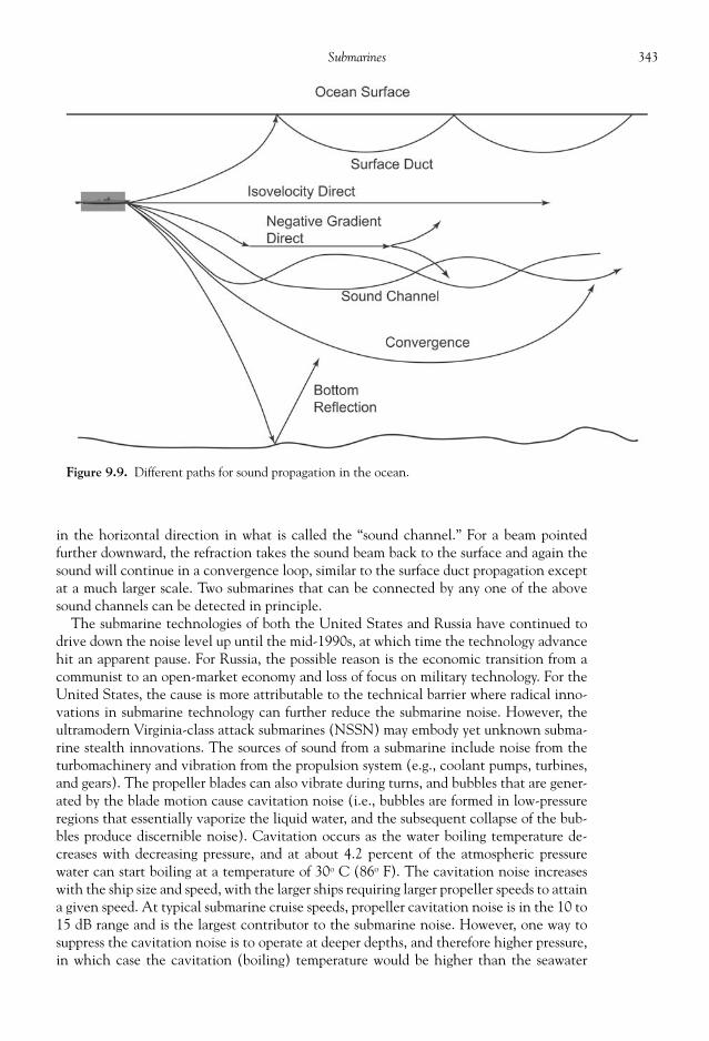
343Submarines
in the horizontal direction in what is called the “sound channel.” For a beam pointedfurther downward, the refraction takes the sound beam back to the surface and again thesound will continue in a convergence loop, similar to the surface duct propagation exceptat a much larger scale. Two submarines that can be connected by any one of the abovesound channels can be detected in principle.
The submarine technologies of both the United States and Russia have continued todrive down the noise level up until the mid-1990s, at which time the technology advancehit an apparent pause. For Russia, the possible reason is the economic transition from acommunist to an open-market economy and loss of focus on military technology. For theUnited States, the cause is more attributable to the technical barrier where radical inno-vations in submarine technology can further reduce the submarine noise. However, theultramodern Virginia-class attack submarines (NSSN) may embody yet unknown subma-rine stealth innovations. The sources of sound from a submarine include noise from theturbomachinery and vibration from the propulsion system (e.g., coolant pumps, turbines,and gears). The propeller blades can also vibrate during turns, and bubbles that are gener-ated by the blade motion cause cavitation noise (i.e., bubbles are formed in low-pressureregions that essentially vaporize the liquid water, and the subsequent collapse of the bub-bles produce discernible noise). Cavitation occurs as the water boiling temperature de-creases with decreasing pressure, and at about 4.2 percent of the atmospheric pressurewater can start boiling at a temperature of 30o C (86o F). The cavitation noise increaseswith the ship size and speed, with the larger ships requiring larger propeller speeds to attaina given speed. At typical submarine cruise speeds, propeller cavitation noise is in the 10 to15 dB range and is the largest contributor to the submarine noise. However, one way tosuppress the cavitation noise is to operate at deeper depths, and therefore higher pressure,in which case the cavitation (boiling) temperature would be higher than the seawater
Figure 9.9. Different paths for sound propagation in the ocean.

344 Military Technologies of the World
temperature. The turbulent fl ow over the submarine body can cause small vibrations of thehull surface to produce detectible sounds as well. Finally, if the sonar is operated in theactive mode, then it generates rather loud telltale signals on the presence and location ofthe submarine. For that reason, active sonar is deployed mostly for target acquisition afterclosing in on the target using passive sonar.
From the detection standpoint, the sensor and analyzer must be sensitive and selectiveenough to pick up the submarine-generated noise described above in the presence of ambi-ent ocean noise. One major contributor to the ambient noise is the surface waves, whichoccur typically at frequencies above 300 Hz. In contrast, maritime shipping vessels alsoadd to the acoustic background, though mostly below 300 Hz. Fish and ocean mammalsgenerate a variety of sounds, and large whales or a group of dolphins also tend to refl ectappreciable sonar signals to add to the complexity of the sound spectra.
In modern submarines, a pump-jet propulsor is used to replace the conventional propel-lers. The pump-jet propulsor operates like a compressor in a gas-turbine engine with arotor/stator combination, where a better control over the water fl ow is applied using thestationary blades (stator) in addition to the rotating ones (rotor). The increased pressurethrough this turbomachinery speeds the water fl ow, which is ejected through a nozzle togenerate thrust, again similar to a gas-turbine engine. The high dynamic pressure delaysthe onset of cavitation, and the blade elements can be better shrouded for sound insula-tion. For the U.S. Navy, the Seawolf- and the newest Virigina-class submarines featurethis type of propulsor, as do the British Trafalgar-, French Le Triomphant-, and RussianBorei-class subs.
The sonar is also used for navigational purposes. The primary method of tracking thesubmarine’s own position is the SINS (ship’s inertial navigation). Onboard accelerometersdetect changes in the ship’s speed in east-west and north-south directions, which can beused to calculate how much the sub has moved in each direction. However, some errorscan creep into the SINS calculations, and a periodic recalibration is made to update theship location. The GPS and celestial navigation require the submarine to come up to atleast periscope depth, either to receive the satellite GPS signals or for visual imaging of thenight sky. An alternate method is to use a sonar fathometer to map the ocean fl oor terrain.Over the operation areas of the submarine, detailed ocean fl oor terrain data are input tothe navigation computer. By using the sonar refl ection from the ocean fl oor, the terraindata can be compared to locate the exact submarine position.
MODERN SUBMARINES
The U.S. Navy deploys the Ohio-class SSBN for missile launch and Los Angeles–, Sea-wolf-, and the ultramodern Virginia-class attack submarines. The fi rst of the Ohio-class submarines were commissioned in the 1970s as SSBNs (i.e., launch platform forSLBMs), and it is expected that they will be in service for up to fi fty years from the date oflaunch. The Ohio-class (Figs. 9.10 and 9.11) is the largest of the submarines built by theU.S. Navy at 560 feet in length and 42 feet in width. Fully submerged, displacement is18,750 tons. The primary mission of the Ohio-class submarines is to provide nucleardeterrent by carrying up to twenty-four Trident II ballistic missiles (Fig. 9.7) with MIRVs(multiple independently targetable reentry vehicles) that can be continuously retargetedusing secure underwater communication channels. Fourteen of the Ohio-class subma-rines are entrusted with about half of the U.S. nuclear arsenal, to be kept at unknown lo-cations and at constant readiness. To maximize the deployment duration, two crews (blueand gold teams) man a given submarine on a rotating basis, and supply and equipment

345Submarines
Figure 9.10. Ohio-class submarine. Photos courtesy of the U.S. Navy.
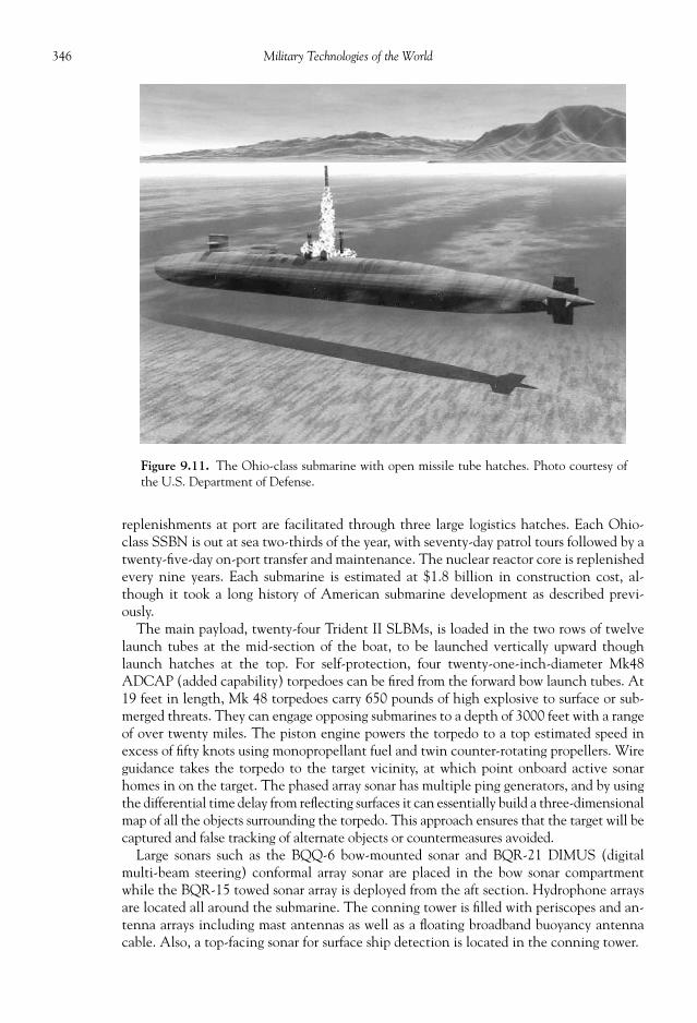
346 Military Technologies of the World
replenishments at port are facilitated through three large logistics hatches. Each Ohio-class SSBN is out at sea two-thirds of the year, with seventy-day patrol tours followed by atwenty-fi ve-day on-port transfer and maintenance. The nuclear reactor core is replenishedevery nine years. Each submarine is estimated at $1.8 billion in construction cost, al-though it took a long history of American submarine development as described previ-ously.
The main payload, twenty-four Trident II SLBMs, is loaded in the two rows of twelvelaunch tubes at the mid-section of the boat, to be launched vertically upward thoughlaunch hatches at the top. For self-protection, four twenty-one-inch-diameter Mk48ADCAP (added capability) torpedoes can be fi red from the forward bow launch tubes. At19 feet in length, Mk 48 torpedoes carry 650 pounds of high explosive to surface or sub-merged threats. They can engage opposing submarines to a depth of 3000 feet with a rangeof over twenty miles. The piston engine powers the torpedo to a top estimated speed inexcess of fi fty knots using monopropellant fuel and twin counter-rotating propellers. Wireguidance takes the torpedo to the target vicinity, at which point onboard active sonarhomes in on the target. The phased array sonar has multiple ping generators, and by usingthe differential time delay from refl ecting surfaces it can essentially build a three-dimensionalmap of all the objects surrounding the torpedo. This approach ensures that the target will becaptured and false tracking of alternate objects or countermeasures avoided.
Large sonars such as the BQQ-6 bow-mounted sonar and BQR-21 DIMUS (digitalmulti-beam steering) conformal array sonar are placed in the bow sonar compartmentwhile the BQR-15 towed sonar array is deployed from the aft section. Hydrophone arraysare located all around the submarine. The conning tower is fi lled with periscopes and an-tenna arrays including mast antennas as well as a fl oating broadband buoyancy antennacable. Also, a top-facing sonar for surface ship detection is located in the conning tower.
Figure 9.11. The Ohio-class submarine with open missile tube hatches. Photo courtesy ofthe U.S. Department of Defense.

347Submarines
Four additional Ohio-class SSGN submarines (shown in Fig. 9.12) are used for conven-tional warfare, where each of the twenty-four SLBM tubes is modifi ed to hold seven Tom-ahawk cruise missiles with non-nuclear warheads for a total of 154 cruise missiles. Thisnumber is in excess of any surface ships in the U.S. Navy. With the Tomahawk range,targets of up to a 1000-mile range can be attacked with precision. Similar to SLBMs, thecruise missiles or other weapons can be launched directly from the submarine and providea secure launch platform with global range. ASDS (advanced SEAL delivery system) sub-marines can be mounted on top of the hull, while a lock-out chamber (dry dock shelter)can transfer sixty-six Navy SEAL (sea, air, and land) special forces personnel directly intothe ASDS. The ASDS is a long-range submersible vehicle for clandestine insertion ofspecial forces, with range, speed, and payload. In addition to the Ohio-class SSGNs, theASDS can be adapted to Los Angeles– and Virginia-class attack submarines. The ASDS’smain function is to carry up to sixteen SEALs to the insertion point and is designed for lownoise operation, shock resistance, and sonar and electro-optic sensor capabilities for situ-ational awareness. The latter capabilities are used to scan the insertion point under day/night conditions prior to landing. On completion of the mission, the ASDS can reattachto the host submarine, and the personnel and equipment can be transferred again throughlock-out chamber. The ASDS has a length of 65 feet and a width of 6.75 feet and is pow-ered by a 62-hp electric motor with forward and aft propulsors.
The Los Angeles–class submarines (Fig. 9.14) have been the main nuclear-powered at-tack submarines bearing SSN designations for the U.S. Navy. This class of submarines isalso referred to as the 688-class, after the fi rst of its kind, the SSN-688 “Los Angeles.” Asnoted earlier in this chapter, modern global geopolitics require the attack submarines toperform a multitude of missions, in addition to anti-submarine warfare during carrierescorts. The Los Angeles–class ships were built primarily for the latter purpose, and in thefuture the ultramodern Virginia-class submarines are expected to fi ll the multi-mission
Figure 9.12 . Ohio-class SSGN with advanced SEAL delivery system and cruise missiles. Graphic courtesy ofthe U.S. Navy.

348 Military Technologies of the World
roles. Developed in the early part of 1970s, these submarines combined the speed andstealth technologies available at the time. The antennas and periscopes in the conningtowers can be fully retracted, but in an effort to streamline the submarine exterior the con-ning tower width was minimized. This original design prevented the hydroplanes frombeing rotated to vertical positions during ice-breaking maneuvers. In the later submarines,one of the design changes was to move the hydroplanes to the bow to alleviate the con-ning tower space. Over sixty of these submarines were constructed, with more than fi ftycurrently in service to be eventually replaced by the Virginia-class subs. These submarineswere deployed during the Gulf War of 1991 and in Operation Iraqi Freedom to launch theTomahawk cruise missiles against land targets. The top speed is estimated at thirty-two
Figure 9.13. Tomahawk cruise missile launched from a SSGN. Photo courtesy ofthe U.S. Department of Defense.

349Submarines
knots with an operating depth of 650 feet. Though much smaller than SSBNs, the LosAngeles–class SSN is considered large for an attack submarine, and the size allows a po-tent set of armaments to be carried on board. Fourteen Mk48 ADCAP torpedoes, Toma-hawk cruise missiles, and Harpoon anti-ship missiles can be fi red either through thetorpedo tubes or the vertical launch system with twelve launch tubes on all submarinesbuilt since 1982.
The fi ring of the torpedo or other weapons through the launch tube requires a sequenceof fl ooding and pressurization because the torpedo must go from the low-pressure interiorof the submarine to the outside high-pressure aqueous environment. Initially, the torpedo
Figure 9.14 . Los Angeles–class attack submarine. Photo courtesy of the U.S. Navy.

350 Military Technologies of the World
launch tube is dry while the torpedo is slid into the tube through a breech, similar to acannon. With the breech closed, the tube is fl ooded with seawater and the launch hatchopened. Next, a high-pressure piston ram is activated to raise the water pressure inside thelaunch tube, and this elevated water pressure will eject the torpedo through the hatch.After launch, the tube is vented with high-pressure air, much like the way that the ballasttank is blown to eject seawater, to evacuate the tube for loading of the next torpedo.
The advanced sonar arrays include the TB-23/29 towed array, BQD 5D wide-aperturefl ank array, BQQ 5D/E low-frequency passive/active search and attack sonar, Ametek BQS15 close-range high-frequency active sonar, MIDAS (mine and ice detection avoidancesonar), SADS-TG active detection sonar, and NMRS (near-term reconnaissance system).The NMRS is a remote vehicle that is controlled via a fi ber optic link that carries anAQS-14 side-scan sonar. The NMRS is launched and recovered through the torpedo tube.In addition, an acoustic countermeasure system called AN/WLY-1 automatically activates
Figure 9.15. The periscope room in the Los Angeles–class attack sub-marine. Photo courtesy of the U.S. Navy.

351Submarines
Figure 9.16. Control room of Los Angeles–class submarine. Photo courtesy of the U.S. Department of Defense.
Figure 9.17. Los Angeles–class attack submarine with an ASDS (advanced SEAL delivery system) attached.Photo courtesy of the U.S. Navy.

352 Military Technologies of the World
Figure 9.18 . Torpedo launch tube of Los Angeles–class submarine. Photo courtesy of the U.S.Navy.
Figure 9.19. Mk48 ADCAP torpedo. Photo courtesy of the U.S. Department of Defense.

353Submarines
proper responses to torpedo attacks based on acoustic interception. Based on the acousticsignature of the torpedoes, this system locates, classifi es, and tracks multiple threats andgenerates solutions for the best countermeasure options. One of the earliest acoustic coun-termeasures was a canister that dispensed lithium hydride in the water, used during WorldWar II by German U-boats. This material caused a large amount of gas bubbles to beformed in the water, which acted as a sonar refl ector to confuse the opposing sonar opera-tor. However, the gas bubbles only moved vertically upward while submarines would usu-ally have some horizontal velocity to cause a Doppler frequency shift in the refl ected sonar.This non-change in the acoustic frequency of the gas bubble decoy could be discerned byseasoned sonar operators. This approach is still used in some surface vessels to create a wallof air bubbles that shields the ships by refl ecting most of the probe sonar pings. Anotherapproach is to use active acoustic jammers to generate large-amplitude random noise tooverwhelm the hostile sonar, similar to radar jamming. Also, towed decoys can be dis-pensed from submarines, and the transponder on the decoys is programmed to generateacoustic signals that mimic the refl ection of the hostile targeting sonar signal.
The SSN-21 Seawolf-class submarines (Figs. 9.20 to 9.22) were envisioned to defeat theRussian submarine fl eet carrying SLBMs. To this end, SSN-21 was the most capable of theU.S. submarines in terms of speed, silent stealth, and search-and-destroy sensors and ar-maments. The sail design incorporated both strength and speed for polar ice-breakingmaneuvers to engage the Russian submarines in their own backyards. However, the highcost and the stand-down of the nuclear build-up between the United States and Russiashifted the focus of Navy priorities, and the current plan is to build Virginia-class subma-rines for multi-mission offensive capabilities. Only three of the Seawolf-class boats, out ofthe initial twenty-nine planned, were built at a cost close to $3 billion per boat by theGeneral Dynamics Electric Boat Division. The S6W nuclear power plant is coupled to a
Figure 9.20. Seawolf-class submarine. Photo courtesy of the U.S. Navy.

354 Military Technologies of the World
Figure 9.21. Seawolf-class submarine prior to launch. The four weapons launch tube hatches(closed) are visible behind the bow sonar dome. Photo courtesy of the U.S. Navy.
Figure 9.22. The ship control section of the Seawolf-class submarine control room. Two crewmenman the helm and the hydroplanes control while the dive offi cer oversees their maneuvers. Photocourtesy of the U.S. Navy.

355Submarines
pump-jet propulsor and a secondary submerged electric motor to generate a silent speed ofover 25 knots (28 mph), which is roughly twice that of the Los Angeles–class. The use ofHY-100 steel instead of the HY-80 used in most previous submarines increases the structuralintegrity (and cost), which allows the submarine to operate at depth of up to 2000 feet.HY-80 and HY-100 are both quenched and tempered low-carbon steel alloys used in pressurevessels and large structures requiring high tensile strength, ductility, crack and corrosion re-sistance, and weldability. Both of the steel alloys exhibit favorable properties in the aboveaspects, except that HY-100 is about 27 percent stronger in terms of the yield stress. Theyield stress is the force per unit area (e.g., pressure) beyond which the material will not returnto its original shape, while another measure of material strength called the “ultimate stress”is the amount of stress at which the material will fail. HY-100 has a tensile yield strength of100,000 psi or 680 MPa, meaning that one can hang a weight of 100,000 pounds on a HY-100bar with 1 inch × 1 inch dimensions. In addition to carbon content (0.2 percent), other metalslike chromium, copper, manganese, and nickel are added to the iron base to form the fi nalalloy, which is quenched (rapidly cooled) for strength and tempered (heated) for ductility.
At a submerged displacement of 9173 tons, the Seawolf submarines are substantiallylarger than the 688-class (6927 tons) and thus can carry a much more potent set of arma-ments. There are eight torpedo tubes that can also launch Tomahawk or Harpoon anti-ship missiles in addition to the Mk 48 ADCAP torpedoes. There is also a vertical launchsystem for the missiles, and up to fi fty of the missile/torpedo combinations can be carriedin the magazine.
A photograph of the Seawolf-class submarine control room is shown in Fig. 9.22, wherethe helmsman and planesman sit in front of the wheel to rotate the rudder and the hydro-planes, respectively. They follow orders to turn the submarine heading and pitch angles,and of course they do not see anything other than the instruments and the data monitorsin front of them. The submarines are run on instruments and the good judgment of theoffi cers, aside from occasional side-scan sonar images of the ocean fl oor. To the left of thehelmsman and planesman are the controls for the ballast, manned by another crew. Typi-cally, navigation electronics including inertial, stellar, and GPS guidance panels wouldline the wall on one side of the control room. In the middle of the control room are twoperiscopes, one for general surveillance (typically the Type 18 periscope) and another forsurface attacks. All of the modern optical and imaging technology and more go into theseperiscopes. The Type 18 submarine periscope made by Kollmorgen Electro-Optical, forexample, features multiple levels of optical magnifi cation, image stabilization, a digitalimager, image intensifi cation under low light conditions, color video transfers, and powerassist mechanisms. The viewing modes include day, night, visual, TV/visual, and gyro-tracked, and the digital image sequences can be transferred to high-defi nition televisionand also downloaded to the onboard workstation for image analyses. The image data canalso be directly fed to the submarine weapons management computer. The optical lengthranges from thirty-six to forty-three feet depending on different versions, which provideoptical magnifi cations of 1.5, 6, 12, and 24 with respective fi elds of view of 32, 8, 4, and 2degrees. Behind the periscopes may be a couple of map tables with various monitors toview and plot the submarine path and other displays based on the inertial and other navi-gational data. To the right (starboard) side of the control room are the weapons controlcomputers and panels. The Virginia-class submarine control rooms are similar in overallconfi guration, but most of the instrumentation panels are replaced with LCD and otherfull-display monitors. Also, as shown in the photograph, the control of the helm and thehydroplanes are combined into joystick controls, and LCD displays most of the necessaryship control data. The roles of the traditional helmsman, planesman, dive offi cer, andchief offi cer of the watch are merged into a two-man (called pilot and copilot) group.

356 Military Technologies of the World
Figure 9.23 . A guided missile frigate viewed through a periscope. Photos courtesy of the U.S.Department of Defense.

357Submarines
Figure 9.25. Artistic rendition of the Virginia submarine in an attack mode. Graphic courtesy of the U.S. Navy.
Figure 9.24. The ship control section of the Virginia-class submarine control room where the pilot and thecopilot navigate the ship, away from the traditional four-man group. Photo courtesy of the U.S. Navy.
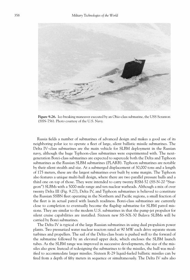
358 Military Technologies of the World
Russia fi elds a number of submarines of advanced design and makes a good use of itsneighboring polar ice to operate a fl eet of large, silent ballistic missile submarines. TheDelta IV–class submarines are the main vehicle for SLBM deployment in the Russiannavy, although the huge Typhoon-class submarines were experimented with. The next-generation Borei-class submarines are expected to supercede both the Delta and Typhoonsubmarines as the Russian SLBM submarines (PLARB). Typhoon submarines are notableby their silent stealth and size. At a submerged displacement of 30,000 tons and a lengthof 175 meters, these are the largest submarines ever built by some margin. The Typhoonalso features a unique multi-hull design, where there are two parallel pressure hulls and athird one on top of those. They were intended to carry twenty RSM-52 (SS-N-20 “Stur-geon”) SLBMs with a 5000-mile range and ten nuclear warheads. Although a mix of overtwenty Delta III (Fig. 9.27), Delta IV, and Typhoon submarines is believed to constitutethe Russian SSBN fl eet operating in the Northern and Pacifi c regions, a small fraction ofthe fl eet is in actual patrol with launch readiness. Borei-class submarines are currentlyclose to completion to eventually become the fl agship submarine for SLBM patrol mis-sions. They are similar to the modern U.S. submarines in that the pump-jet propulsor forsilent cruise capabilities are installed. Sixteen new SS-NX-30 Bulava SLBMs will becarried by Borei submarines.
The Delta IV is typical of the large Russian submarines in using dual propulsion powerplants. Two pressurized water nuclear reactors rated at 90 MW each drive separate steamturbines and propellers. The sail of the Delta-class boats is pushed well to the forward ofthe submarine followed by an elevated upper deck, which encloses the SLBM launchtubes. As the SLBM range was improved in successive developments, the size of the mis-siles also grew. Instead of redesigning the submarines to fi t the missiles, the hull was mod-ifi ed to accommodate larger missiles. Sixteen R-29 liquid-fueled ballistic missiles can befi red from a depth of fi fty meters in sequence or simultaneously. The Delta IV subs also
Figure 9.26. Ice-breaking maneuver executed by an Ohio-class submarine, the USS Scranton(SSN-756). Photo courtesy of the U.S. Navy.
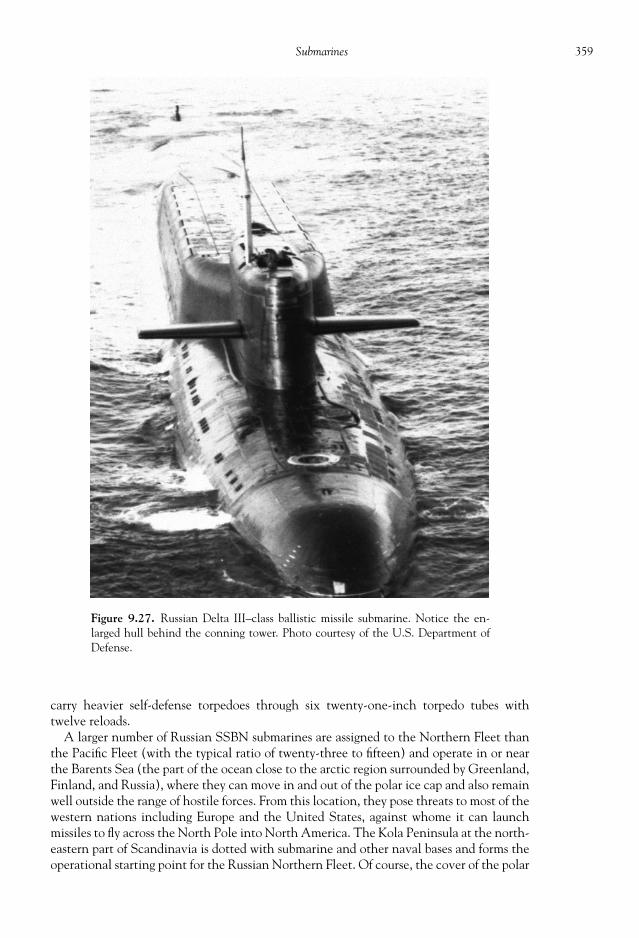
359Submarines
carry heavier self-defense torpedoes through six twenty-one-inch torpedo tubes withtwelve reloads.
A larger number of Russian SSBN submarines are assigned to the Northern Fleet thanthe Pacifi c Fleet (with the typical ratio of twenty-three to fi fteen) and operate in or nearthe Barents Sea (the part of the ocean close to the arctic region surrounded by Greenland,Finland, and Russia), where they can move in and out of the polar ice cap and also remainwell outside the range of hostile forces. From this location, they pose threats to most of thewestern nations including Europe and the United States, against whome it can launchmissiles to fl y across the North Pole into North America. The Kola Peninsula at the north-eastern part of Scandinavia is dotted with submarine and other naval bases and forms theoperational starting point for the Russian Northern Fleet. Of course, the cover of the polar
Figure 9.27. Russian Delta III–class ballistic missile submarine. Notice the en-larged hull behind the conning tower. Photo courtesy of the U.S. Department ofDefense.

360 Military Technologies of the World
ice and proximity between Russia and North America works both ways in that U.S. sub-marines can easily penetrate this short-cut for quick strikes against Russia’s main cities aswell. Much of Russia’s northern coast is adjacent to the Arctic Sea, but the bulk of thearctic region is international waters, open to any ships or submarines capable of navigatingin it. From North America, the Arctic Sea can be entered from the Canadian north coastor through the narrow Bering Strait between Alaska and the eastern tip of Russian Siberia.Navigation through the Bering Strait is notoriously diffi cult due to the possibilities ofgrounding and collision with ice. High-frequency active sonar can be used to map the icefi eld, but this of course would defeat the stealth operation if used in excess.
The region under the polar ice cap fl uctuates seasonally and now with global warming,but nonetheless spans an area close to that of the United States. Detailed oceanographicdata including the ocean fl oor terrain maps are of vital interest to both sides. Russia, given
Figure 9.28. Russian Victor-class submarine. Photo courtesy of the U.S. Department of Defense.

361Submarines
their immediate access to this region and longer experience, is believed to have more ex-tensive knowledge of this strategic location, although using the use of modern side-scansonar and infrared sensors give the U.S. submarines some advantages in navigating inuncharted territories. In particular, the entry regions tend to be shallow and tortuous, butthe central waters are up to 4000 meters deep, much deeper than submarine operatingdepths. The ocean fl oor below and the ice cap above dictate the operation of submarines.The submarines break through the ice partially to receive long-range satellite communica-tions and navigation inputs and fully to launch the missiles. Thus, the ice-breaking capa-bility is an important element in SSBNs. A natural opening or thin ice can be used ifdetected through upward-looking echo sounders or infrared or visual periscope sightings.Ice thickness fl uctuates, and some icebergs can protrude down to some 400 meters belowthe surface, requiring vigilant navigation.
REFERENCES
Compton-Hall, Richard. Submarine vs. Submarine: The Tactics and Technology of Underwater Warfare .London, UK: Orion Books, 1988.
Miller, David, and Chris Miller. Modern Naval Combat . Malaysia: Crescent Books, 1986. Polmar, Norman. The American Submarine . Annapolis, MD: The Nautical and Aviation Publishing
Company of America, 1983.
Figure 9.29 . Russian Oscar II–class cruise missile submarine OMSK (K-186). Photo courtesy of the U.S.Department of Defense.

This page intentionally left blank

TECHNOLOGY DOES NOT win wars by itself, but in the hands of able commanders andtroops superior war technologies have time and again altered the way the battles are foughtand won. Historical events to this date are most signifi cantly affected by armed confl icts,and since the beginning it must have been a fascination and often a matter of life anddeath for men to seek better ways to defeat or defend against adversaries.
Military technology now encompasses uses of the full three-dimensional world includ-ing land, air, space, and the ocean depths. Operations in each domain present unique ad-vantages and challenges, and a wide variety of machines have been invented or modifi edto suit military needs. For this reason, almost all branches of science and engineering con-tribute toward these varied military technologies. Just looking at modern aircraft like theF-22 Raptor, perhaps the most advanced aircraft and avionics technologies go into this$300 million aircraft. Aircraft technology is not limited to the conventional aerodynam-ics, combustion physics (for the gas-turbine engine), and structural mechanics but extendsto material science, electrical engineering, and computer science for the stealth capabili-ties, advanced radar designs, target tracking and weapons management software, andmany others, all of which cannot be listed in this paragraph. Even benign sciences likeoceanography contribute to military applications by allowing sonar signals to be properlyinterpreted through available data in remote parts of the ocean like the Arctic Oceanunderneath the ice cap. As is well documented, the development of the atom bombs inthe 1940s involved the most prominent physicists and engineers in the United States atthe time (several of them Nobel laureates). The pursuit of knowledge on the structure of thecosmos somehow led to the principle of nuclear reactions (E = mc2 ) by Albert Einstein.This is one example of why the fundamental knowledge, most of which is arguably ad-vanced through the best minds in universities (Note: The author happens to work in auniversity), is so important not just in terms of its military applications but for the poten-tial to have far-reaching effects on broad aspects of technology and ultimately the way oflife itself.
Advances in technology do not occur without investments, and in many instances sig-nifi cant portions of the national economic output are expended for the military. TheUnited States in the twenty-fi rst century exemplifi es the focus on military budget alloca-tions, with its defense budget far outpacing any other nation on earth. In fact, the U.S.military budget of $440 billion comprised about half of the total military expenditures byall the industrialized nations in the world in fi scal year 2007. China, expected to overtake
CHAPTER
10
PERSPECTIVES ONMILITARY TECHNOLOGY

364 Military Technologies of the World
even the U.S. economy by 2030, is beginning to exert its newly acquired wealth in itsmilitary spending but comes in as a distant second at $63 billion in its defense budget.After some shaky years following the break-up of the Soviet Union, Russia manages amilitary spending that is at a similar level to China. The European powers, Japan, SouthKorea, and Saudi Arabia all have suffi ciently sound economies and justifi cations to spend$20 billion to $50 billion in defense. To put the defense spending in perspective, the U.S.defense budget of $440 billion in 2007 represents about 16 percent of the total federalspending. Out of the $440 billion, most of the money goes into operations and mainte-nance ($152 billion), procurements ($84 billion), and personnel ($111 billion), but alarge amount is also invested in technology development ($73 billion). In comparison thelargest non-military research funding goes to the National Institute of Health with a fund-ing of $28 billion in 2007. Other major non-military research organizations such as theNational Science Foundation and Department of Energy received a relatively small $6billion and $9 billion, respectively in 2007. Although much of the military research anddevelopment is geared toward specifi c battlefi eld devices and systems, substantial researchis also conducted that may impact future technologies, both military and commercial.Thus, it can be said that the current budget allocations in the United States is a continu-ation of the historical trend by superpowers or empires, except at an unprecedented scale.With such heavy investment, military research and developments are often the primedrivers of technology across the board.
The cost of maintaining military technology and presence over extended periods oftime and territory can weaken or crumble an empire from the foundation, its economy.Although the former Soviet Union initially kept pace or even excelled in some areas ofmilitary technology such as space vehicles, submarines, and fi ghter aircraft, by 1990 thecost of research and development of advanced technology had escalated far beyond thelevel that could be sustained by its economy. The imbalance in military spending overother domestic needs fostered a gradual weakening of its internal social, political, andeconomic structure. In that sense, the Cold War was won more by the economic prowessof the United States in being able to fund military technologies of increasing capabilitiesand cost. China and Japan already possess capabilities for advanced technology, militaryand civilian, and as noted previously China is expected to become the world’s largesteconomy by 2030. In the present and the future, the ability of a nation to exert its infl u-ence through military means will depend on a sound economy to sustain the military andcivilian industry. Technology will allow the nation to secure or develop much needed re-sources such as energy, water, and environment, making it impervious to instabilities inthe rest of the world. Hopefully, this is where future “wars” will be fought, a competitionin developing advanced technologies so that important resources may be acquired withoutthe need for armed confl icts. The need to maintain strong armed forces, however, contin-ues to be present in the foreseeable future because the world is quite capable of producing yetunpredictable threats to humanity, particularly in times of presumed peace. It is then the jobof scientists and engineers to equip such armed forces with the best technology available.
Behind all the technologies discussed in this book are the people who recognized andfostered innovative ways to accomplish martial feats and often employed them to gooduse. Rarely has technology alone been superior to the determination, organization, resource-fulness, and perseverance of men. Even the best of technology in the long run can notreverse the course of motion erroneously set by misguided leaders, and conversely evenwith primitive technologies people have overcome much more formidable foes. Therefore,as exulting as most of the technology described in this book may be, military technologyis only a means to achieve political objectives. If the objectives themselves are wrong,then no technology can reverse or make them right.

365Perspectives on Military Technology
Another common denominator in military technologies is the innovativeness of thepeople who invent, build, and fi nd use for them. For the simple reason that military tech-nology frequently determined the fate of many in the most consequential manner, thebrightest minds were always sought and drawn to this business. Albert Einstein himselfcontributed to the development of nuclear weapons, to later regrets. The best Americanphysicists and engineers during the latter part of World War II relocated to a remote NewMexico site to participate in the Manhattan Project to develop the fi rst atom bombs,which were to be used against Japan. Archimedes is known for a number of siege and de-fense weapons, and in fact he himself was killed after a two-year siege of his city of Syra-cuse in Sicily, which ultimately collapsed. Today, thousands of Ph.D.s and research staffwork in government, private, and university laboratories on research and developmentprojects funded by the U.S. Department of Defense. Some of the development work mayinvolve direct use of technology in weapons, but a large majority of the research mayinvolve what appears to be benign science such as understanding the exact mechanismsof metal corrosion, fl ow characteristics at hypersonic speeds, image analysis algorithms torecover data under extremely noisy images, and many others with potential for militaryuse. Some of these technologies fi nd very useful and lucrative uses in the commercial sec-tor in communications, astronomy, aviation, manufacturing, and electronics. Whenthese advances in technologies, fueled by strong economies, are focused toward militaryapplications over sustained periods, then the discrepancy in the level of technology wouldbe such that those in possession of them will have potentially insurmountable powerover those who do not. As noted previously, this statement is restricted to situationswherein the technology is used by people capable of exercising such power judiciouslyand effi ciently. Perhaps one small step toward such ideal use of military technology isan understanding of the various military technologies and their power, limitations, andapplications.
The use of technology in warfare is not limited to hardware. All the advanced sensorsand smart weapons used during the Iraq Wars would have been far less effective if not forthe advanced computer software used to synthesize vast amounts of data fed from a multi-tude of sensors and an automated algorithm used to assign the optimum weapons for thetargets. This software integration to hardware is increasingly important given the advancesin optical and electromagnetic sensors for battlefi eld situational awareness and the com-plexity of the weapon systems. The most potent weapons developed in history, nuclear-tipped ballistics missiles, rely on onboard computer hardware and navigation software toreach the target within a 100-meter radius after traveling thousands of miles. Advancedfi ghter aircraft are controlled in principle by computers in so-called fl y-by-wire controls,where the pilot input is converted to appropriate digital commands to the aerodynamicssurfaces. The Aegis combat system combines an array of radars and weapon systems to de-tect, track, and engage a large number of targets in the air, on the surface, and in the oceandepths. Powerful scanned array radars in the Aegis combat system can track up to 100targets within a 100-miles radius, and the tracking data are fed to fi re control computers todeploy and guide the missiles. The Aegis system also controls the anti-missile defenseweapons such as Standard SM-2 missiles capable of knocking down hostile missiles aimedat friendly ships. Hardware and software upgrades are underway so that the missile defensesystem can be used as a theater-wide shield against ballistic missiles.
Although we mostly focus on the hardware aspects in this book, the tactics and strate-gies to maximize the given weapons hardware may be considered an important element inthe optimum applications of the military technology. Numerous examples exist wheresimilar levels of technology in weapons and men were put to such effective use againstadversaries, such as to build empires as in the Greek phalanx, the simple but devastating

366 Military Technologies of the World
use of cavalry by the thirteenth-century Mongol warriors, highly coordinated blitzkriegattacks by the German army, carrier-based aircraft bombing, and so on. The organized in-fantry using phalanx originated during the agrarian periods of the Greek city states, whereordinary citizens doubled as warriors in times of need. Wearing armor made of metal andwood weighing up to seventy-fi ve pounds made individual, isolated battle a thankless task,particularly in the undulating terrains of the Greek peninsula. Instead, a tight wall of bronzeshields was formulated by men marching in close ranks that could span anywhere from afew hundred yards to a mile or more in later larger battles involving 10,000 to 30,000 in-fantrymen. The fi rst three rows (fi ve in the Macedonian phalanx) of the phalanx had longspears solidly fi xated forward. A disciplined phalanx formation was a formidable sight forless organized defense or even cavalry. Repeated attempts by the Persian armies to over-take Greek cities were repulsed each time by organized and disciplined defense involvingphalanx in spite of the fact that the Greeks were massively outnumbered. The ability toshield themselves while extending attacking spears has in many ways a parallel in modernbattle tanks, where the advanced armor can protect against both high explosive and ki-netic energy rounds. The long spears are now replaced by tank main guns that can reg-ister kills at up to three miles’ range.
The following Roman Empire over extended territories necessitated their armies tofi ght on much more varied terrains and circumstances and against different adversaries. Inplace of static phalanx formation, the Romans opted for a much more fl uid style of warfareand a different set of weapons. Rectangular shields called “scutum,” double-edged shortswords, replaced the Greek round shields and long spears. Also, notably a projectileweapon of sort, javelins, now became a standard component in the Roman fi ghting units.After the initial thrust by the light infantry and cavalry to bring the opposing army towithin 50 to 200 yards, a group of men called “hastati” came forward to throw their jave-lins among the enemy ranks. Using the confusion thus induced, they accelerated forwardto crush the enemy formations. The job was usually fi nished by supporting lines of sword-wielding infantry. Thus, one of the early organized uses of projectile weapons was thejavelin. Of course, the range and impact of projectile weapons would soon greatly increasein siege machines, and much later through the use of black powder introduced to the westby the Mongols. Projectile weapons afford relative safety to the “throwing” side, and withmodern ICBMs with global range extending to trajectories in outer space the entire worldis potentially targeted.
Another military technology the Romans excelled in was construction of fortifi cations.To consolidate their territorial gains, the Romans built urban centers to govern surround-ing areas and also to defend against hostile encroachments. The stone architecture oframparts became precursors to medieval castles rising to dimensions that could not bedefeated by contemporary armies. These fortifi ed urban centers served during peacetime asplaces for government, commerce, manufacture, and religious practices, and during war-time it could sustain large armies. The choice of location and the investment made intheir structural integrity made these ramparts impregnable during the height of Romanpower, with or without relief forces. Hostile forces could not bypass these fortifi ed citiesbecause their line of supply could easily be broken by armies attacking from these citybases, and besieging these strongholds was even more diffi cult, requiring many resourcesover extended periods of time. The besieging army also risked being attacked from bothsides if relief forces arrived to launch coordinated attacks with those inside the fortifi ca-tion. The siege machines existed but lagged in their development because the rampart wallscould always be made taller and thicker. Battering rams, catapults, and trebuchets wereused, sometimes in conjunction with siege towers or earthen ramps. It was with the adventof gunpowder that effective siege machines came into existence: cannons. Gunpowder has

367Perspectives on Military Technology
had a far-reaching impact on the military technology since the time that Mongols demon-strated its effectiveness during their unprecedented sweep of territory ranging from Koreato the gateways of Vienna. Gunpowder of course is used in guns and cannons, but it couldalso be used to fi re missiles over long distances. These are the primary weapons of manymilitary machines of today, from infantry weapons and tank guns to aircraft missiles, cruisemissiles, and intercontinental ballistic missiles. The cannons for siege warfare requiredexcessive size.
One of the guns used in the 1400s by the Turks was called the Dardanelles Gun, and itwas used to fi re granite stones weighing 1500 pounds in a thirty-inch caliber barrel. It issaid that this gun required sixty oxen and 400 men just to place it in fi ring position. LaterGerman artillery guns are also notorious for their size, as in Big Bertha and the SchwereGustav gun with an 800-mm caliber barrel.
Gunpowder has revolutionized warfare since its introduction to Europe in the four-teenth century, although the development took several centuries before guns and artillerybecame the primary weapons on the fi eld. In a treatise on military practices by Christinede Pisan in 1409, trebuchets and other medieval siege machines are placed equal in impor-tance to the cannons, and records of use of trebuchets in siege battles exist as late as 1420.Because artillery required barrel material and design to be of suffi cient effectiveness, initialartillery use was more for the shock and incendiary effects. However, by the middle of thefi fteenth century cannons were knocking down traditional castle walls and gates withregularity. Superior metallurgical know-how soon led to even bigger and better guns. Har-fl eur, one of the many English strongholds in Normandy that had withstood sieges ofweeks and months against lesser cannon fi re, was made a short work of by the advancedbronze guns employed by Charles VII. The bronze casting method used in the manufactureof these guns was originally developed and refi ned over the years for making large andelaborate church bells. Charles VII of France went on to sweep through the Italian penin-sula by being able to mobilize lighter but powerful bronze guns.
The architects of this period were commissioned to build ever bigger and stronger bas-tions for defending against artillery barrage. Logistic locations were sought to make thebest use of terrain to keep the opposing artillery at bay, while huge vertical walls wereconstructed along with interlocking gun positions moats, and multiple walls within themain wall. These gigantic feats of architectural and civil engineering resulted in a series ofartillery fortresses throughout Europe in the sixteenth century. For a pentagonal citadel atAntwerp commissioned in 1567, for example, 650,000 cubic yards of earth needed to beremoved to lay out the foundation, and 221,000 cubic yards of masonry were then used toerect a monumental defensive position. This gives a preview of the recurring theme inmilitary technology where defensive capabilities are more diffi cult and costly to produceand maintain than offensive technology. Regardless of the scale and design of the artilleryfortresses, the cannon technology would allow construction of bigger and more powerfulcannons at much lesser cost than constructing monumental fortresses. In later years, pow-erful projectiles were constantly developed to penetrate defensive armors, such as the ba-zookas that could knock out German tanks during World War II, again with a minor costfor the offensive weapon and a high risk for the armored vehicle. Nowadays, long-rangemissiles can threaten helicopters, aircraft, destroyers, and carriers, while numerous exam-ples exist in something as simple as rocket-propelled grenades downing multimillion-dollarhelicopters. In its extreme, ballistic missile defense systems can end up costing trillions ofdollars whereas offensive weapons to over-saturate known systems could be produced at afraction of the cost. The offense holds the initiative and can thus select the time, place,and methods of its attack while minimizing its exposure, and therefore it is often mucheasier to destroy than to protect.

368 Military Technologies of the World
Guns took even longer to reach acceptance, because personal weapons needed to bereliable, quick, and lethal enough to be used in hectic battlefi elds. The fi rst guns, with longand heavy barrels, required two men or a wooden support to operate, and their initial im-pact and accuracy were less than those of crossbow. Although guns’ effectiveness graduallyincreased, even into the World War II era and beyond, a bayonet was a standard equip-ment to be attached to the end of rifl es in case of close combat, ammunition shortage,or mechanical failures. Reliable ignition of the gunpowder in muskets was of particularimportance, and fl intlocks (devices to generate frictional sparks) were in use well into thenineteenth century. Gun technology in Europe was more or less equally developed due toa rapid spread of technology. However, in Japan it was only through the early Portuguesesailors that the harquebus became known to some of the warlords, including Oda Nobu-naga. Quickly realizing its potential impact, Nobunaga ordered mass production of theseguns and training of foot soldieries, in the process discarding the age-old tradition of “hon-orable” sword fi ghts and opting for pragmatic lethal devices. Using a three-tiered fi ringsquad to compensate for the slow loading process of matchlock harquebuses, Nobunagascored a series of victories against other warlords to bring most of Japan under his control.
Once the mechanics of gun and cannon operations were understood and manufacturingtechnology caught up to allow some of the innovative ideas to be implemented, gun tech-nology then rapidly accelerated, coinciding with the broad advances in technology broughton by the Industrial Revolution. Rifl ed barrels, improved gun propellant, percussion locks,breech loading, along with simply better production methods and materials kept adding tothe accuracy and potency of these weapons. One of the notable inventions is the machinegun, particularly the Gatling design patented in 1861. The use of rotating barrels crankedmanually brought the fi ring rate to several hundred rounds per minute. The Gatling gunssaw limited action during the American Civil War, during which troop losses were alreadymore than 600,000. Machine guns in later years, most notably World War II, would bringthe human loss to catastrophic levels when coupled with the industrial basis to mass-producethese devices and the outdated tactics of pitting men against these killing machines.
The fi rst tanks were the outcome of a massive effort to overcome the bogged-downtrench warfare of World War I. Although cannons were put on the tanks to give some of-fensive capabilities, the primary use of the tank was to break through the trench defensesto make way for the infantry. These large behemoths were less than mobile, crawling at 3to 4 mph speeds, and the cannons only fi red six-pound rounds with very limited views ofthe outside world. Of course, some visionaries of warfare foresaw the potential effective-ness of tanks, and much work went into refi ning this machinery. By the time of the nextworld war, tanks were the primary methods of armed maneuvers with unprecedented mo-bility and power. This would lead to the classic era of tank battles, involving legendarycommanders like Rommel and Patton. By combining mobility with armor and cannonpunch, a force was created for land battles that could only be stopped by a force of equalcapabilities, another tank. The mobility was based on oil-burning diesel engines. Many ofthe other highly mobile war machines would also be fueled by oil-derived products, gaso-line, diesel, or jet fuels. To wage a war, oil became as important as basic necessities, and theentire world economy and war machinery would start to revolve around secure sources andsupply of oil.
Rockets, aircraft, and submarines are later developments, relatively speaking. Much moreelaborate science and engineering were needed to make these devices work let alone forrugged military applications. Crude rockets did exist from long ago, and in fact one of thefi rst uses of black powder in China was to put it in bamboo tubes to be boosted toward theenemy. Such unguided rockets have been used since then in various forms, but it was notuntil some understanding of the mechanics of motion, including the effects of gravity,

369Perspectives on Military Technology
acceleration, and aerodynamic forces, was achieved that the rockets could be used withsome level of control over long distances. German V-1 and V-2 rockets, using differentpropulsion methods, are considered to be the fi rst systematic use of such guided missiles.Although military minds around the world were all keen on using this technology as theweapon of the future, some of the most signifi cant progress in rocketry was made by thosewith visions of reaching outer space with these vehicles. Reach outer space they did, butthe technology also allowed the most potent weapons of all kinds, nuclear warheads, to besent to outer space and then come down in ballistic trajectories over global ranges withprecision.
The development of the airplane was also initially fueled by the pure pursuit of the de-sire to be able to fl y. Few during the exciting days of the early airplanes foresaw the use ofthese slow, fragile machines for war purposes. From existing accounts, aerial battles arosesimply out of necessity or animosity to shoot down reconnaissance airplanes from the op-posing side during World War I. The French had used balloons for reconnaissance duringthe Napoleonic wars (1803 to 1815) and also in the Franco-Prussia War (1870). Airplanesof course offered much better mobility and control, and as early as 1914 the British wereusing biplanes to observe the German troop movements by sending as many as a dozen ofthese aircraft into the air. Some of these observations were crucial and in many ways supe-rior to ground reconnaissance. Soon, the French and Germans were fl ying observationairplanes as well, and one way to restrict one another’s reconnaissance capabilities was totry to shoot them down. Service pistols gave way to machine guns, and Germans showedtheir innovativeness by designing a new type of airplane with speed, lightness, and arma-ment specifi cally developed to shoot down slower reconnaissance airplanes. Thus beganthe classic age of aerial duels with fi ghter aircraft that have now morphed into some of themost advanced and expensive technological objects in history.
The ability to maneuver in the ocean depths was no easier a task to accomplish. A crudebarrel-shaped submersible invented by an American named David Bushnell during theRevolutionary War accomplished nothing militarily due to the diffi culty of controllingthe vessel and in deploying any weapons. However, American submarines now embodythe best available technology in submarine architecture, propulsion, stealth, and armament,again at a high price tag of about $2 billion for Ohio-class ballistic missile submarines. Thelong-range intercontinental ballistic missiles, long-range bombers, and ballistic missile sub-marines incorporate some of the most advanced technology and constitute the most lethaltriad of nuclear weaponry possessed by the United States, Russia, and several other states.
Digital electronics have revolutionized almost all aspects of military technology. Ana-log gauges and controls have given way to digital displays and computer controls in air-craft. Radar and communication equipment have become more powerful and yet muchmore compact. Various sensors now allow perception of the surroundings under all-weatherconditions, night and day. These vision systems are now integrated to the weapon systemsfor aiming on targets as quickly as the operator can turn his eyes. Complex fl ight and targetdata can be displayed on heads-up displays so that both visual and digital information caneasily be grasped by the pilot in modern fi ghter aircraft. Controls also have been integratedin so-called HOTAS (hands-on throttle and stick) where airplane motion, weapon sys-tems, and communication devices can all be controlled simultaneously. Even the tradi-tional hydroplane and rudder controls on submarines are now being converted to digitalsystems involving simple control sticks. Digital imaging sensors operating at various elec-tromagnetic wave frequencies transmit real-time imagery of the minute objects on the earth’ssurface from spy satellites. High-speed computers can help process tons of data being up-loaded by sensors to prioritize hundreds of objects of surface and airborne targets in modernbattle management systems such as Aegis.

370 Military Technologies of the World
Given the recent pace of technological advances, we may still have one or two revolu-tionary leaps left that may again completely alter military paradigms and how wars arefought. It is in the hands of a select group of individuals to understand all the implicationsof such paradigm shifts and apply them to the best advantages of the nation that theyprotect and serve.
REFERENCES
Boot, Max. War Made New, Technology, Warfare, and the Course of History, 1500 to Today . New York:Gotham Books, 2006.
Parker, Geoffrey (ed.). The Cambridge Illustrated History of Warfare . New York: Cambridge UniversityPress, 1995.
Friedman, George and Meredith. The Future of War, Power, Technology and American World Domi-nance in the 21st Century . New York: Crown Publishers, 1996.
For more information on the U.S. military budget breakdown, see en.wikipedia.org/wiki/Military_budget_of_the_United_States.

A-4 rocket, 68 A-4 Skyhawk, 11 A-6E attack aircraft, 311 A-7 Corsair II, 11 A-10 attack aircraft, 43 – 44 A-12 aircraft, 159 AA-11 Archer, 81 AA-12 Adder, 81 – 82 AAQ-13/14 LANTIRN system, 5 , 18 , 183 – 84 AAT-52 machine gun, 240 advanced SEAL delivery system (ASDS), 347 ,
351 advanced targeting forward-looking infrared
(ATFLIR), 13 Aegis battle management system, 300 – 301 , 365 aerial combat, 42 – 48 Aerobee rocket, 71 aerostatic support, 314 – 15 afterburners, 25 – 26 AGM-88 HARM missile, 100 – 101 , 311 AGM-84 Harpoon, 97 , 122 AGM-114 Hellfi re missile, 63 – 64 , 121 AGM-114K Hellfi re II missile, 98 AGM-114L Longbow Hellfi re missile, 98 AH-1 Cobra helicopters, 125 – 28 AH-1W Super Cobra helicopter, 128 AH-56A Cheyenne helicopter, 109 AH-64 Apache helicopter, 3 , 107 – 10 , 116 – 17 Aichi D3A Val, 35 – 36 AIM-7 Sparrow missile, 80 AIM-9 Sidewinder missile, 44 , 79 – 80 AIM-54 Phoenix missile, 63 – 64 , 79 AIM-120 ASRAAM Slammer missile, 76 – 79 AIM-132 ASRAAM, 80 airborne early warning and control systems
(AWACS), 163 – 66 airborne early warning systems, 162 – 66 aircraft carriers, 287 – 89 , 296 , 305 – 11 , 316 – 17 aircraft technology, 1 – 61
aerial combat tactics, 42 – 48 aerodynamics, 59 – 61
armaments, 30 – 42 armor, 31 , 34 avionics and controls, 48 – 59 carrier-based strike groups (CVSG), 287 – 89 ,
296 fi ghter tactics, 35 – 37 , 42 – 48 fl ight formation, 41 – 42 gas-turbine engines, 24 – 30 historical overview, 30 – 42 long-range bombers, 37 – 41 spy planes, 154 – 59 stealth capability, 9 , 156 unmanned aerial vehicles (UAVs), 159 – 62 World War II aircraft, 30 – 42See also surveillance technology
air cushion vehicles (ACV), 314 – 15 air-launched ballistic missiles, 198 , 202 air-to-air missiles (AAMs), 75 – 82 AK-47 (Kalashnikov) rifl e, 234 – 35 Albacore-class submarines, 336 ALE-50 AAED, 15 Alexander the Great, 139 Almaz satellite, 146 – 47 ammunition belts, 239 AMRAAM (Advanced Medium-Range
Air-Air) missiles, 44 , 63 humvee-launced AMRAAM
(HUMRAAM), 90 – 91 , 94 – 95 radar technology, 172 surface-launched AMRAAM
(SLAMRAAM), 90 – 91 AN/AAS-35 Pave Penny, 18 angle-on jamming (AOJ), 177 – 78 AN/SQS-53 sonar system, 303 anti-aircraft missiles, 91 – 95 anti-ballistic missile (ABM) defense systems.
See missile defense systems anti-missile defense systems. See missile defense
systems anti-radiation missiles (ARMs), 96 – 97 anti-satellite systems, 217 – 18
Index

372 Index
anti-ship missiles (AShMs), 96 – 97 , 297 helicopter-launched, 120 – 21 submarine-launched, 349 , 355
anti-submarine technology depth charges, 122 , 299 helicopters, 136 – 38 Los Angeles-class submarines, 347 – 53 missiles, 122 rocket (ASROC), 299 sonar, 301 – 5
anti-tank missiles, 275 – 76 , 277 ground-launched (ATGMs), 98 – 100 helicopter-launched, 120 – 21
anti-tank shot, 259 – 61 , 264 AN-TPS-75 air surveillance radar, 171 AQS-13 sonar system, 305 AQS-18 sonar system, 303 AR-10 and AR-15 rifl es, 231 – 32 Arirang satellite, 148 Arleigh Burke-class destroyer, 292 – 93 armor-piercing (AP) shot, 261 , 264 – 65 Armor-Piercing Fin-Stabilized Discarding
Sabot (APFSDS) projectiles, 264 – 65 arrest wires, 308 – 11 Arrow anti-ballistic missile, 208 – 9 artillery. See guns and artillery assault rifl es. See guns and artillery Atlas rocket, 72 – 73 atomic bombs, 194 – 96
See also nuclear weapon technology attack helicopters. See helicopter technology Audace destroyer, 293 AUF1 self-propelled gun, 284 – 85 AUG/HBAR machine gun, 239 automatic guns, 229 – 30 Azimuth Only (AZON) bombs, 18 AZUR armor kit, 272
B-1B Lancer, 13 – 15 B-2 Spirit aircraft, 15 – 17 , 178 – 80 B-2B bomber, 17 B-17 Flying Fortress, 37 – 39 , 163 B-25 Mitchell, 40 B-29 Superfortress, 39 – 41 B-52 bombers, 140 B-83 nuclear bomb, 202 BA3 Sea Skua missile, 121 – 22 Balao-class submarines, 329 , 331 ballast tanks, 339 – 41 ballistic missile defense (BMD). See missile
defense systems ballistic missile early warning system
(BMEWS), 151 , 170 , 175 – 76 ballistic missile submarines (SSBN), 198 , 338 – 39
ballistics, 248 – 50 balloons, 162 , 369 barrage jamming, 177 barrage rockets, 69 – 70 barrel roll attack, 44 Basov, Nikolai G., 219 battlefi eld air-targeting micro-air vehicle
(BATMAV), 159 – 60 Battle of Trafalgar, 289 – 90 bazookas, 69 beam-riding guidance, 84 beam weapons, 210 – 11 , 214 – 15 , 218 – 20 Bessemer, Henry, 239 BGM-109 Tomahawk cruise missile, 104 – 5 Big Bertha artillery, 244 – 45 bin masking, 177Black Hawk Down movie, 109 black powder, 65 – 66 , 221 – 22 , 250 , 366 – 67 Blunderbuss gun, 225 boats. See naval technology; submarine
technology body armor, 253 Bohr, Neils, 193Book of Fighting (Hassan ar-Rammah), 222 Borei-class submarine, 344 Boyle, Willard, 148 Bradley fi ghting vehicle (BFV), 276 , 278 – 79 ,
282 – 83 breech-loading cannon, 244 breech-loading rifl e, 226 – 27 , 228 Breguet, Louis, 136 Brilliant Pebbles project, 215 Brown Bess, 225 budget allocations, 363 – 64 buoyancy, 315 – 16 Bushnell, David, 322 , 369
calorimetry, 186 cannons. See guns and artillery capture air bubble vehicle (CAV), 314 carrier strike groups (CVSG), 287 – 89 , 296 ,
316 – 17 aircraft carriers, 305 – 11 anti-submarine technology, 347 – 53 carrier air wing (CVN), 311 – 14
catapults, 308 – 10 Cavelli shot, 244 Centurion tank, 276 chaff, 177 Challenger 2 tank, 271 – 72 charge-coupled device (CCD) digital imaging
systems, 142 , 148 chariots, 253 Charles VII of France, 367

373Index
Charlie-class submarines, 338 CH-47 Chinook, 130 – 32 CH-53E Super Stallion helicopter, 127 – 29 , 136 chemical lasers, 219 Chien Hsueh-Sen, 147 China 3 satellites, 147 Chinese military spending, 363 – 64 Chiormy Oriol tank, 269 Chobham armor, 263 – 64 , 271 Churchill, Winston, 255 civilian applications, 365 closed-in weapon system (CIWS), 292 , 297 – 98 ,
299 – 300 Coast Guard Jayhawk helicopter, 125 Cobra Dane phased array radar, 151 Colt revolver, 227 – 28 Colt .44 Magnum handgun, 229 – 30 combat information center (CIC) aircraft, 163 combined sensor systems, 5 , 18 , 183 – 84 command guidance, 83 – 84 commercial applications, 365 communication intelligence (COMINT), 149 communication satellites, 217 – 18 composite materials, 134 – 35 , 263 – 64 Congreve rockets, 66 – 67 conventional take-off and landing (CTOL), 10 cordite, 228 – 29 Corona (KH) satellites, 142 – 46 corvettes, 291 Cosmos satellite, 146 – 47 costs of military technology, 363 – 64 Cresap, Michael, 226 cruise missiles, 64 , 86 , 104 – 5 , 122 , 202 cruisers, 292 – 95
Daepodong series missiles, 199 Dardanelles gun, 243 , 367 d’Ascanio, Corradino, 135 decoys, 215 – 17 defense spending, 363 – 64 defense support program (DSP), 151 Delta-class submarines, 339 , 358 – 59 Delta II rocket, 74 – 75 , 76 depleted uranium, 267 depth charges, 122 , 299 Derringer pistol, 227 desert warfare, 274 – 79 destroyers, 291 – 94 digital scene matching and correlation
(DSMAC), 141 displacement vessels, 315 – 16 Distant Early Warning (DEW) system, 151 dogfi ghts, 42 – 48 Dong Feng missiles, 199
Dorand, Rene, 136 double-base propellants, 102 double horizontal spring, 260 Drebbel, Cornelius, 322 Dulles, John, 196 Duralumin, 31 – 32 , 34
E-2C Hawkeye aircraft, 1 – 2 , 311 E-3 Sentry AWACS aircraft, 163 – 64 , 165 EA-6B Prowler aircraft, 165 , 311 , 313 – 14 E-8 aircraft, 165 EA-61 Prowler, 172 EADS Tiger helicopter, 133 – 34 early warning systems, 150 – 52 , 162 – 66
ballistic missile early warning system(BMEWS), 170 , 175 – 76
Joint Functional Component Commandfor Intelligence, Surveillance, andReconnaissance (JFCCR-ISR), 205
USSTRATCOM, 204 – 6 EC-121 aircraft, 163 EC-135 Statolifter aircraft, 165 , 202 EF-111 Raven, 3 Einstein, Albert, 363 , 365 electronic countermeasures (ECM) and
counter-countermeasures (ECCM), 176 – 78
electronic intelligence (ELINT) program, 149 electronic support measures (ESM), 175 ELINT (electronic intelligence) program, 143 ELITE coupon method, 186 Ericsson, John, 317 Eurofi ghter, 23 – 24 European Tornado, 60 excimer lasers, 219 – 20 exoatmospheric reentry vehicle, 213 Exocet missile, 97 , 297 , 298 explosively-formed projectiles (EFP), 265 explosive reactive armor (ERA), 264 extended-range Poseidon (EXPO) missile, 335 external ballistics, 248 – 49
F-4 Phantom aircraft, 4 , 48 – 53 F6F-3 Hellcat aircraft, 34 F-14 Phantom II aircraft, 11 F-14 Tomcat aircraft, 1 – 2 , 11 , 60 , 311 F-15 Eagle aircraft, 4 – 5 , 27 – 29 , 53 – 54 , 60 F-16 Fighting Falcon aircraft, 6 , 54 – 55 , 59 – 60 F-22 Raptor aircraft, 1 , 6 – 10 , 172 , 363 F-35 Lightening II Joint Strike Fighter aircraft,
1 , 10 – 11 F100-PW-229, 30 F101-GE-102, 30 F107-WR-101, 29 – 30

374 Index
F110-GE-100, 30 F-117 Nighthawk aircraft, 3 , 140 F-117A aircraft, 178 – 80 F118-GE-100, 30 F119-100 turbofan engine, 26 – 28 F/A-18 Hornet aircraft, 2 , 55 – 58 , 61 , 311 – 13 F/A-18 Super Hornet aircraft, 11 – 13 F/A-22 Raptor aircraft, 60 FADEC (dual-redundant digital engine
controls), 10 false targets, 177 FAMAS rifl e, 235 Fanhui Shi Weising satellites, 147 Fermi, Enrico, 193 Feynmann, Richard, 193 FIM-92 Stinger missile, 63 – 64 , 94 – 95 Fitch, John, 317 Flettner, Antoine, 136 fl intlock mechanism, 225 – 27 Focker-Wulf Fw 190 Wurger, 31 folding-fi n aerial rocket (FFAR), 119 Ford tank, 257 Forsyth, Alexander, 227 forward fi ring aircraft rocket (FFAR), 70 forward-looking infrared sensors (FLIR), 58 ,
109 , 183 frigates, 291 Fuller, J.F.C., 255 , 257 – 58 Fulton, Robert, 322 – 23
G force, 310 G36 rifl e, 235 – 36 GALOSH anti-ballistic missile, 210 , 212 gamma ray radiation, 191 gas-operated reloading mechanism, 230 gas-turbine engines, 24 – 30 , 103 – 4 , 279 – 80 Gatling gun, 238 , 368 Gato-class submarines, 329 – 31 GAU-8/A Avenger gun, 43 – 44 GE 225, 117 GE M134 minigun, 118 – 19 GE M61 Vulcan, 42 – 44 , 118 – 19 GE XM214 Microgun, 118 George, John, 254 Georges Heygues destroyer, 293 George Washington-class submarines, 336 Goddard, Robert H., 67 – 68 GPS guidance systems, 85 – 86 , 141 , 218 , 344 GRAB (galactic radiation and background)
satellite, 143 greater underwater propulsive power (GUPPY),
331 ground-based mid-course defense (GMD)
system, 211 – 14
ground-target missiles, 96 – 100 Groves, Leslie, 332 Gruman Avenger, 163 guerilla warfare, 142 guidance systems. See missile guidance systems guided weapon systems (GWS), 297 – 98 Gulf War. See Operation Desert Storm gun cotton, 228 – 29 , 250 gunpowder, 65 – 66 , 221 – 22 , 250 , 366 – 67 guns and artillery, 221 – 50
assault rifl es, 234 – 36 , 240 ballistics, 248 – 50 black powder, 65 – 66 , 221 – 22 , 250 grenade launchers, 234 historical overview, 221 – 34 , 238 – 39 , 242 – 45 howitzers, 246 – 48 machine guns, 117 – 19 , 238 – 41 mortars, 245 – 46 propellants, 228 – 29 , 233 , 245 , 250 recoil, 229 – 30 , 239 , 244 ship-based, 299 – 300 sniper rifl es, 236 – 38 special applications scoped rifl e (SASR),
238 gun-type fi ssion bombs, 194 – 95
hands-on throttle and stick (HOTAS) controlsystem, 369
Harpoon missile, 97 , 112 , 298 – 99 , 349 , 355 harquebus-matchbox mechanism, 223 – 24 , 368 Hasan ar-Rammah, 222 Hatsuyuki destroyer, 293 head-mounted display (HMD), 109 heads-up-display (HUD), 5 , 53 – 58 , 55 – 58 , 109 ,
172 helicopter technology, 107 – 38
attack helicopters, 107 – 10 fl ight mechanism, 111 – 17 high-strength materials, 134 – 35 historical overview, 135 – 36 machine guns, 117 – 19 military helicopters, 122 – 34 naval helicopters, 136 – 38 rocket launchers, 119 – 22
Helios satellites, 147 – 48 HH-60G Pave Hawk helicopter, 113 high-explosive (HEAT) shot, 261 , 264 – 65 , 277 high explosive plastic (HEP) rounds, 265 high-test peroxide (HTP), 320 – 22 , 341 high velocity aircraft rocket (HVAR), 70 High-Velocity Armor-Piercing Fin-Stabilized
Discarding Sabot (HPAPFSDS)projectiles, 264 – 65
high yo-yo maneuver, 44 – 47

375Index
Hiroshima, 193 historical overviews, 365 – 69
aircraft technology, 30 – 42 guns and artillery, 221 – 34 , 238 – 39 , 242 – 45 helicopter technology, 135 – 36 missile technology, 65 – 75 naval technology, 288 – 91 nuclear weapon technology, 193 – 98 submarine technology, 322 – 39 tank technology, 253 – 62
HMS Lusitania, 326 Holland, John P., 323 – 24 Holt, Benjamin, 255 – 56 Hotel-class submarines, 338 howitzers, 246 – 48 Hubble Space Telescope, 144 Hughes M230 Chain Gun, 117 – 18 human intelligence (HUMINT), 139 , 149 Humvee, 285 humvee-launced AMRAAM (HUMRAAM)
missile, 90 – 91 , 94 – 95The Hunt for Red October , 320 Huntley, H. L., 323 Hydra 70 rocket, 120 hydrodynamic support, 314 – 16 hydrofoils, 314 – 16 hydrogen bombs, 194 – 96 hydrostatic support, 315 – 16
IFF data system, 58 – 59 , 175 image intelligence (IMINT), 149 image intensifi ers, 181 implosion fi ssion bombs, 194 – 95 improvised explosive devices (IED), 184 – 86 IMR-4475 propellant, 233 inertial (GPS) guidance, 85 – 86 , 141 Information Gathering Satellites, 148 infrared guidance, 85 in-line engines, 34 – 35 innovation, 365 integrated helmet and display sight system
(IHADSS), 109 , 117 – 18 integrated sensor suite (ISS), 161 intelligence. See surveillance technology intercontinental ballistic missiles (ICBMs),
63 – 64 , 72 – 75 , 96 , 189 , 198 – 203 , 366 intermediate-range ballistic missiles (IRBMs),
74 – 75 , 198 internal ballistics, 248 – 49 Invincible-class carriers, 296 , 307 Iraq war and occupation. See Operation Iraqi
Freedom ironclad warships, 290 – 91 Israeli Six-Day War, 274 – 76
jamming, 176 – 77 jet propulsion, 318 joint direct attack munition (JDAM), 19 Joint Functional Component Command for
Intelligence, Surveillance, and Reconnais-sance (JFCCR-ISR), 205
joint stand-off weapon (JSOW), 19 – 20 joint surveillance target attack radar system
(JSTARS), 164 – 66 Jouffroy D’Abbans, Claude de, 317 Jupiter rocket, 72 , 203 – 4 , 334 Ju-87 Stuka, 35 – 36
K-1 tank, 273 K1/A1 tank, 268 K-19 submarine, 338 K-141 Kursk submarine, 320 – 22 , 338 Ka-27 helicopter, 131 – 32 Ka-50 helicopter, 132 – 33 Kentucky rifl e, 225 kevlar, 134 – 35 keyhole satellites, 143 KG-9 Big Bird satellite, 143 – 44 KH satellites, 142 – 46 Kh-31 Zvezda missile, 299 Kidd-class destroyer, 292 – 93 kinetic-energy projectile guided missile, 210 – 11 Krag Jorgenson bolt-action rifl e, 230 – 31
L-class submarines, 323 – 24 Lacrosse satellite, 142 Lafayette-class submarines, 336 lag pursuit roll, 44 – 46 land-based missiles, 198 – 203 LANDSAT satellites, 149 laser-beam weapons, 210 – 11 , 214 , 218 – 20 laser-guided bombs (LGB), 17 – 20 launch and recovery element (LCE), 161 lead pursuit, 44 – 45 leaf spring, 260 le Bourgeoys, Marin, 225 Leclerc tank, 272 Leopard series tanks, 272 – 73 Le Triomphant-class submarine, 344 LGM-30G Minuteman III, 198 – 202 Lightweight Fighter (LWF) program, 6 linked cartridges, 239 liquid-propellant rockets, 100 – 103 Llya Muromets bomber, 31 Lobnitz, N. J., 239 lock-on after launch (LOAL) guidance, 98 lock-on before launch (LOBL) guidance, 98 Loon missile, 332 Los Angeles-class submarines, 344 , 347 – 53

376 Index
low altitude navigation and targeting infraredfor night (LANTIRN), 5 , 18 , 183 – 84
low-earth orbit (LEO) satellites, 217 – 18 low yo-yo maneuver, 44 , 46 , 47 Lunar Orbiter, 143
M1 rifl e, 230 – 31 M1 series tanks, 263 – 68 M1A1 Abrams tank, 265 – 68 , 276 , 278 – 79 M2 machine gun, 238 M2A2 Bradley fi ghting vehicles, 276 , 278 – 79 ,
282 – 83 M3 Bradley fi ghting vehicles, 276 , 282 – 83 M3M machine gun, 240 M4 carbine, 232 , 234 M4 Sherman tank, 261 – 62 M14 rifl e, 231 – 32 M16 rifl e, 231 – 34 M40 sniper rifl e, 236 M48 tank, 276 M60 series tanks, 263 , 276 M61 Vulcan machine gun, 241 – 42 M65 Atomic Cannon, 245 M82 sniper rifl e, 238 M109 Paladin 155 mm howitzer, 247 – 48 M109A6 Paladin self-propelled howitzer,
284 – 85 M113 armed personnel carrier, 283 M119 105 mm howitzer, 246 – 47 M120 mortar, 246 M134 minigun, 241 M151 HE warhead, 120 M203 grenade launcher, 234 M-220 TOW missile, 98 – 100 M229 HE warhead, 120 M230 Chain Gun, 117 , 118 , 241 M249 machine gun, 241 M252 mortar, 246 M255A1 Flechette warhead, 120 M257 Illumination warhead, 120 M260 LWL rocket launcher, 120 M261 high-explosive multipurpose
submunition (MPSM), 120 M261 LWL rocket launcher, 120 M264 Red Phosphorus smoke warhead, 120 M267 Practice round warhead, 120 M270 multiple rocket launch system (MLRS),
285 M278 IR Flare warhead, 120 M500 sniper rifl e, 237 M1895 machine gun, 239 M1903 rifl e, 230 machine guns. See guns and artillery MAC-10 machine gun, 240
MAG machine gun, 239 – 40 , 241 magnetic anomaly detectors (MAD), 136 – 37 magnetic resonance detection, 186 main ballast tank (MBT), 339 – 40 Manhattan Project, 193 , 196 , 363 , 365 manual line-of-sight guidance (MCLOS), 83 Mark I tank, 255 Mark IV tank, 255 – 56 Mark V tank, 259 mass spectrometry, 186 Maxim, Hiram, 239 medium-range ballistic missiles, 198 MEKO 360 destroyer, 293 Merkava tank, 274 Merlin 130 engine, 35 MH-53 Sea Dragon helicopter, 130 , 137 MH-53J Pave Low helicopter, 109 MH-60G Pave Hawk helicopter, 124 – 26 MH 60R Sea Hawk helicopter, 125 – 26 Mi-24 helicopter, 133 Mi-28 helicopter, 133 microchannel plates, 181 Midas (Missile Defense Alarm System), 151 MiG-21 Fishbed, 4 MiG-23 Flogger, 1 – 2 , 4 MiG-25 Foxbat, 4 – 5 MiG-29 Fulcrum, 1 , 4 , 20 – 21 MiG-31, 20 MiG-35, 1 MiG-35 Fulcrum E, 20 military budgets, 363 – 64 MIM-23 Hawk missile, 91 – 92 MIM-104 Patriot missile, 91 – 94 mine warfare ships, 291 Minuteman III missile, 198 – 202 Mirage F1, 4 Missile Defense Alarm System (Midas), 151 missile defense systems, 63 , 206 – 17
decoys, 215 – 17 naval use, 297 – 98 satellite surveillance, 218
missile guidance systems, 82 – 87 , 210 – 11 beam-riding guidance, 84 command guidance, 83 – 84 inertial (GPS) guidance, 85 – 86 infrared guidance, 85 radar guidance, 84 – 85 terrain contour matching (TERCOM), 86 track-via-missile (TVM guidance), 85 wire-guidance, 83 – 84
missile technology, 63 – 105 air-to-air missiles (AAMs), 75 – 82 anti-aircraft missiles, 91 – 95 anti-tank ground missiles (ATGMs), 98 – 100

377Index
cruise missiles, 104 – 5 decoys, 215 – 17 ground-target missiles, 96 – 100 guidance systems, 64 – 65 , 82 – 87 , 98 helicopter-launched missiles, 119 – 22 historical overview, 65 – 75 propulsion, 64 , 100 – 104 submarine-launched missiles, 331 – 32 surface-to-air missiles (SAMs), 87 – 96
Mitsubishi A6M Zero, 33 Mk2 Penguin missile, 120 – 21 Mk16 Weapons Group, 300 Mk23 reentry vehicle, 198 – 99 MK 66 rocket motor, 120 monopropellant, 122 mortars, 243 , 245 – 46 MQ-1 Predator, 160 – 61 multifunction display (MFD), 53 multiple independently targetable reentry
vehicles (MIRVs), 197 – 99 , 207 , 215 , 335 multiple-launch rocket systems (MLRS), 96 multipurpose submunition (MPSM), 120 mutually-assured destruction (MAD), 196 – 97 MX Peacekeeper missile, 199 , 201
Nagasaki, 193 , 195 Narwhal-class submarine, 337 Nautilus-class submarine, 333 Nautilus submarine (Fulton), 323 Nautilus submarine (SSN-571), 333 Naval Ocean Surveillance System (NOSS),
143 naval technology, 287 – 318
air wing (CVN), 311 – 14 anti-missile defense systems, 297 – 98 battle management system, 300 – 301 carrier strike groups (CVSG), 287 – 89 , 296 ,
305 – 11 , 316 – 17 closed-in weapon system (CIWS), 292 ,
297 – 98 , 299 – 300 destroyers and cruisers, 291 – 95 fl otation support, 314 – 16 frigates, 291 historical overview, 288 – 91 naval vessel architecture, 314 – 17 nuclear power, 295 – 96 , 332 – 33 , 338 , 341 – 42 SEALs, 347 sonar, 301 – 5 speed and propulsion, 317 – 18 vertical short take-off and landing (VSTOL)
aircraft, 306 weapons systems, 296 – 301
navigation forward-looking infrared(NAVFLIR), 12
NAVSTAR GPS system, 218 Nelson, Horatio, 289 – 90 night vision systems, 5 , 18 , 58 , 109 , 180 – 84 Nimitz-class aircraft carrier, 307 – 11 nitrocellulose, 228 – 29 , 250 Nobel, Alfred, 228 Nobunaga, Oda, 224, 368 noise jamming, 176 – 77 November-class submarines, 337 – 38 NSV series machine guns, 240 nuclear early warning system, 150 – 52 nuclear magnetic resonance (NMR), 137 , 186 nuclear radiation, 191 nuclear weapon technology, 189 – 208 , 365
beam weapons, 220 blast impact, 190 delivery methods, 198 – 204 early warning systems, 204 – 6 historical overview, 193 – 98 intercontinental ballistic missiles (ICBMs),
63 – 64 , 72 – 75 , 96 , 189 , 198 – 203 , 366 missile defense systems, 206 – 15 multiple independently targetable reentry
vehicles (MIRVs), 197 – 99 , 207 , 215 , 335 nuclear-tipped cruise missiles, 203 , 365 nuclear winter, 192 radiation, 190 – 91 submarine-launched ballistic missiles
(SLBMs), 64 , 198 – 200 , 203 – 4 , 332 , 334 – 36
world’s arsenal of nuclear weaponry, 192 – 93
Ofeq satellite, 148 Ohio-class submarines, 204 , 344 – 47 , 358 OH-58 Kiowa Warrior helicopter, 121 , 276 OH-68 Kiowa Warrior helicopter, 109 Operational Objective Camera (OCC), 158 Operation Desert Shield, 2 Operation Desert Storm, 17 – 20 , 139 – 41 ,
276 – 79 , 314 Operation Iraqi Freedom, 2 – 3 , 18 , 141 , 314 Oppenheimer, J. Robert, 193 Oscar II class submarine, 320 – 22 , 361
P-47 Thunderbolt, 32 P-51 Mustang, 32 – 33 , 38 P-500 Bazal missile, 98 PAC-1, -2, and -3 missiles, 91 – 93 Panther tank, 259 , 261 Panzer tanks, 257 – 59 , 261 Paris Gun artillery, 244 particle-beam weapons, 210 – 11 , 214 – 15 Patriot missile, 91 – 94 , 208 – 9 Patton, George, 368

378 Index
Pavelow helicopter, 3 Paveway LGB, 18 – 19 Pepperbox pistol, 227 percussion fi ring, 227 perimeter acquisition radar attach characteriza-
tion (PARCS) system, 151 Pershing tank, 263 Phalanx CIWS weapon system, 292 , 297 – 98 ,
299 – 300 phased-array radar (APG-75), 167 pilot night vision system (PNVS), 108 – 9 Pisan, Christine de, 367 pistol-carbine gun, 228 PK series machine guns, 240 – 41 plan position indicator (PPI), 173 Polaris missile, 203 – 4 , 332 , 334 – 35 Poppy satellite, 143 Porsche, Ferdinand, 258 Poseidon missiles, 203 , 335 – 36 precision acquisition vehicle entry phased array
warning system (PAVE PAWS), 151 , 176 , 205
precision bombs, 17 – 20 principal anti-air missile system (PAAMS),
298 Prokhorov, Aleksander M., 219 proportional navigation, 86 – 87 PSG-1 sniper rifl e, 237 Puckle gun, 238 – 39 pump-jet propulsor, 344
quadruple resonance detection, 186 Quebec-class submarines, 338
R-series missiles, 199 R-1 rocket, 71 R-5M rocket, 71 R-5 rocket, 71 R-7 rocket, 72 R-7A rocket, 72 R-12 rocket, 72 R-14 rocket, 72 R-1820-97 Cyclone engine, 38 radar cross-section (RCS), 9 radar technology, 151 , 163 , 167 – 76
ballistic missile early warning system(BMEWS), 175 – 76
electronic countermeasures (ECM) andcounter-countermeasures (ECCM), 176 – 78
electronic support measures (ESM), 175 frequency bands, 168 – 69 guidance systems, 84 – 85 IFF data system, 175
magnetic anomaly detectors (MAD), 136 – 37 phased-array radar (APG-75), 167 precision acquisition vehicle entry phased
array warning system (PAVE PAWS), 151 , 176 , 205
synthetic aperture radar (SAR), 5 , 155 , 174 transmitters, 172 – 73 unmanned aerial vehicles (UAVs), 159 – 62
radial engines, 34 – 35 radioactivity, 191 ramjet engine, 103 – 4 recoil, 229 – 30 , 239 , 244 reconnaissance. See surveillance technology Redstone rocket, 71 – 72 Regulus missile, 332 research and development, 365 RGM-84A Harpoon missile, 298 – 99 RH-53 Sea Stallion helicopter, 136 Ricardo, H. R., 259 rifl es. See guns and artillery RIM-2 Terrier, 95 RIM-8 Talos, 95 RIM-24 Tartar, 95 RIM-66 missile, 95 – 96 RIM-67 SM-2 missile, 95 – 96 RIM-161 SM-3 missile, 96 rocket engine propulsion, 100 – 103 rocket launchers, 119 – 22 , 152 – 54 rocket projectile (RP), 70 Rommel, Erwin, 258 – 59 , 368 rotor hubs, 113 – 15 RQ-2 Pioneer, 160 RQ3 Dark Star, 160 RQ-4 Global Hawk, 160 – 62 RQ-5A/MQ-5A/B Hunter, 160 RQ-7A/B Shadow 200, 160 RQ-11B Raven B, 160 Russian military spending, 363 – 64
S-3B VIking aircraft, 311 SA series missiles, 88 – 90 SA-2 missile, 89 SA-7 missile, 90 SA-14 missile, 90 SA-15 Gauntlet missile, 90 Sagger anti-tank missile, 275 – 76 salinity, 301 SAR-Lupe satellites, 147 – 48 satellite and missile observation system
(SAMOS), 143 satellite technology, 142 – 50
anti-missile systems, 214 – 15 anti-satellite systems, 217 – 18 communication satellites, 217 – 18

379Index
digital imaging systems, 144 – 46 , 148 – 49 early warning satellites, 218 fi lm-loaded systems, 142 – 44 GPS systems, 218 Midas (Missile Defense Alarm System), 151 multi-wavelength detectors, 149 NATO satellites, 147 – 48 orbital mechanics, 152 – 54 Soviet satellites, 146 – 47
SB2C Helldiver, 35 – 36 SBD Dauntless, 35 – 36 Schawlow, Arthur, 219 schlieren imaging, 248 – 49 Schweiger, Walther, 325 – 26 scissors maneuver, 45 – 46 , 48 Sea Dart missile, 297 – 98 Sea Harrier, 10 SEALs (sea, air, and land special forces), 347 Seawolf-class submarines, 342 , 344 , 353 – 55 self-forging fragment (SFF) plate charge, 265 self-propelled howitzers, 283 – 85 semi-active radar guidance, 84 – 85 semi-automatic line-of-sight guidance
(SACLOS), 83 semi-automatic pistol, 229 – 30 SG 550 sniper rifl e, 237 SH-3 Sea King helicopter, 138 , 305 SH-60 Seahawk helicopter, 137 – 38 SH-60B helicopter, 131 SH-60F Seahawk helicopter, 115 , 136 Shaw, Joshua, 227 ships. See naval technology; submarine
technology ship’s inertial navigation (SINS), 344 short-takeoff and vertical landing (STOVL)
aircraft, 10 – 11 , 307 Sidewinder missile, 2 signals intelligence (SIGINT), 149 Sikorsky, Igor, 136 Sinah-1 satellite, 148 single vertical spring, 260 Skipjack-class submarines, 333 – 34 , 336 SLAM-ER Block 1F missile, 97 SM-2ER BLock IV missile, 96 Smith, George E., 148 Smith and Wesson revolver, 228 SM-2 missile, 95 – 96 smokeless powder, 228 – 29 sniper rifl es, 236 – 38 solid-propellant rockets, 100 – 102 sonar, 137 , 301 – 5 , 331 , 344 , 360 – 61 Sound Surveillance Systems (SOSUS) sonar
system, 303 Sovre-mennyy destroyer, 293
Soyuz spacecraft, 147 space warfare, 189 – 220
anti-satellite systems, 217 – 18 beam weapons, 218 – 20 missile defense systems, 206 – 17 nuclear weapons, 189 – 206
special applications scoped rifl e (SASR), 238 spending considerations, 363 – 64 Spitfi re, 31 – 32 , 35 spot jamming, 177 Springfi eld Armory rifl es, 230 – 31 Spruance-class destroyer, 291 – 92 Sputnick satellite, 333 – 34 spying. See surveillance technology SQR-19 TACTAS sonar array, 303 SR-71 Blackbrid, 51 , 155 – 59 SS series missiles, 199 SS-1 Scud rocket, 71 SS-3 Shyster rocket, 71 SS-N-12 Sandbox, 98 Standard missiles, 95 – 96 Standard SM-3 missile, 208 – 9 stealth capability, 9 , 156 , 178 – 80 , 319 steam-powered vessels, 317 Stern, Albert, 255 Steuben, Friedrich von, 226 stick powder, 233 strategic bombers, 198 Strategic Defense Initiative (SDI), 207 , 211 strategic submarine-launched ballistic missiles,
203 Sturgeon-class submarine, 337 Su-22 Fitter aircraft, 4 Su-25 Frogfoot aircraft, 4 Su-27 Flanker aircraft, 20 Su-30 Flanker-C aircraft, 1 , 20 – 23 Su-33 Flanker-D aircraft, 20 , 23 Su-34 Fullback aircraft, 21 submarine-launched ballistic missiles (SLBMs),
64 , 198 – 200 , 203 – 4 , 332 , 334 – 36 submarine technology
advanced SEAL delivery system (ASDS), 347 , 351
anti-submarine warfare, 347 – 53 Balao-class submarines, 329 , 331 ballast tanks, 339 – 41 ballistic missile submarines (SSBN),
198 – 200 , 203 – 4 , 331 – 32 , 334 – 37 , 338 – 39 diesel-electric power, 341 Gato-class submarines, 329 – 31 German U-boats, 324 – 29 historical overview, 322 – 39 ice-breaking, 353 , 358 , 360 – 61 Kursk accident, 320 – 22 , 338

380 Index
submarine technology (cont’d) Los Angeles-class submarines, 344 magnetic anomaly detectors (MAD), 136 – 37 navigation, 344 , 360 – 61 nuclear power, 332 – 33 , 338 , 341 – 42 Ohio-class submarines, 344 – 47 propulsion, 331 – 33 , 341 – 42 , 344 Seawolf-class submarines, 344 , 353 – 55 sonar, 331 , 344 , 360 – 61 sound propagation, 342 – 44 stealth, 319 , 343 – 44 Thresher accident, 336 – 37 Virginia-class submarines, 343 – 44 , 355 – 57
Sun Tzu, 139 Super Magnum sniper rifl e, 237 surface-launched AMRAAM (SLAMRAAM)
missile, 90 – 91 surface-to-air missiles (SAMs), 87 – 96 surveillance technology, 139 – 86
airborne early warning systems, 162 – 66 electronic countermeasures (ECM) and
counter-countermeasures (ECCM), 176 – 78
IED detection, 184 – 86 intelligence failures, 141 night vision systems, 180 – 84 nuclear early warning system, 150 – 52 radar, 163 , 167 – 76 sonar, 137 , 301 – 5 spy planes, 154 – 59 spy satellites, 142 – 54 stealth capability, 9 , 156 , 178 – 80 unmanned aerial vehicles (UAVs), 159 – 62
SVD semi-automatic sniper rifl e, 237 Svezda Kh-31 missile, 97 – 98 synthetic aperture radar (SAR), 5 , 155 , 174
T-26A tank, 256 T-34 tank, 261 T-54 tank, 276 T-55 tank, 274 – 76 , 277 T-62 tank, 274 – 76 T-69 tank, 270 , 276 T-72 tank, 268 – 69 , 276 , 278 , 279 T-80 tank, 268 – 69 T-90 tank, 269 T-99 tank, 269 – 71 TADS (target acquisition/designation system),
108 tailhooks, 310 – 11 tank technology, 253 – 85
anti-tank missiles, 259 – 61 , 264 , 275 – 76 , 277
armor, 259 – 61 , 263 – 64 , 271 , 272
Bradley fi ghting vehicle (BFV), 276 , 278 – 79 , 282 – 83
desert warfare, 274 – 79 guns and ammunition, 267 – 68 , 283 – 85 historical overview, 253 – 62 Humvee, 285 M113 armed personnel carrier, 283 M270 multiple rocket launch system
(MLRS), 285 power train, 279 – 81 self-propelled howitzers, 283 – 85 tracks, 281 – 82
Technical Objective Camera (TEOC), 158 Technology Experiment Satellite, 148 Teller, Edward, 196 terrain contour matching (TERCOM), 86 , 141 testudo formation, 253 TF30-P-111, 30 TF34-GE-100, 30 thermal imaging, 5 , 18 , 58 , 109 , 181 – 83 thermal radiation, 190 – 91 Thor-Able combination rocket, 74 Thor rocket, 72 , 74 Thresher-class submarine, 336 – 37 Ticonderoga-class missile cruiser, 294 – 95 Tiger tank, 261 Tikhonravov, Mikhail, 146 Tiny Tim rocket, 70 Tippoo Sahib, 66 Tirpitz, Alfred, 323 – 24 Titan (I-IV) rockets, 72 – 74 , 150 Tomahawk cruise missile, 3 , 104 – 5 , 140 – 41 ,
348 – 49 , 355 Topol-M missile, 214 TOW missile, 98 – 100 , 120 – 21 Townes, Charles H., 219 tracked armored vehicles. See tank technology track-via-missile (TVM guidance), 85 Trafalgar-class submarine, 344 Trident I C-4 missile, 335 – 36 Trident II D-5 missile, 335 – 36 Triton submarine, 333 Tsiolkovsky, Konstantin Edvardovich, 67 tube-launched TOW missile, 98 – 100 turbofan engine, 103 turbofans, 25 – 2620,000 Leagues under the Sea (Verne), 323 Type 74 tank, 274 Type 89 tank, 256 Type 92 tank, 256 Type VII U-boat, 326 – 27 Type IX-C U-boat, 327 Type XXI U-boat, 327 – 28 Typhoon-class submarines, 358

381Index
U-boat submarines, 324 – 29 U-2 Dragon Lady, 48 , 50 , 152 , 154 – 55 UGM-73 Poseidon missiles, 203 , 335 – 36 UGM-93A/B Trident missile, 198 – 99 , 200 , 203 UGM-96A missile, 335 – 36 UH-1 Cobra helicopter, 109 UH-1 Huey helicopter, 117 – 18 , 122 – 24 UH-60 Black Hawk helicopter, 109 , 111 , 117 ,
124 – 26 , 136 Ulam, Stansilaw, 196 unconventional warfare, 142 undersea long-range missile system (ULMS), 335 unmanned aerial vehicles (UAVs), 159 – 62 U.S. Strategic Command (STRATCOM), 151 USS Eisenhower carrier strike group, 288 USS Enterprise, 288 , 296 USS Harry S. Truman, 292 – 95 USS Holland submarine, 323 – 24 USS Iowa, 294 USS James Mason, 335 USS John C. Stennis, 310 USS Memphis, 322 USS Missouri, 294 USS Patrick Henry, 334 USS San Jacinto, 294 – 95 USS Shoup, 304 USS Thresher submarine, 336 – 37 USSTRATCOM, 204 – 6 USS Virginia submarine, 319 – 21
V-1 rocket, 68 , 332 , 369 V-2 rocket, 68 – 69 , 70 – 72 , 369 V-22 Osprey helicopter, 130 , 132 variable-geometry inlets, 28 – 29 variable-geometry nozzles, 26 – 28 variable-wing geometry, 13 – 14 velocity pursuit, 86 – 87 Verne, Jules, 323
vertical short take-off and landing (VSTOL)aircraft, 306
Vickers Medium C tank, 259 Vickers Medium Mark II tank, 256 Victor-class submarine, 360 Viking rocket, 71 Virginia-class submarines, 343 – 44 , 355 – 57 von Braun, Werner, 68 , 72 von Karman, Theodore, 68 Vympel R-73 (AA-11 Archer), 81 Vympel R-77 (AA-12 Adder), 81 – 82
W-5 helicopter, 136 warships. See naval technology; submarine
technology Washington, George, 139 WC846 propellant, 233 Weddigen, Otto, 324 Whiskey-class submarine, 338 White Cloud satellite, 149 Whitehead, Robert, 323Widowmaker , 320 wire-guidance, 83 – 84 WV-1 aircraft, 163
X-1 rocket, 70 – 71 Xm214 microgun, 241 X-ray lasers, 220
Yamato battleship, 292 Yankee-class submarines, 338 – 39 Yantar satellite, 146 – 47 Yokosuka D4Y Suisei Judy, 35 – 36
Zenit satellite, 146 Zeppelin-Staaken R VI, 31 Zircon satellites, 147 – 48 Zizka, John, 253

This page intentionally left blank

T.-W. LEE is an Associate Professor of Mechanical and Aerospace Engineering at ArizonaState University. He has worked on research funded by the U.S. Army, Air Force, Depart-ment of Energy, and National Science Foundation, and by Orbital Sciences Corporation.He has also authored over eighty technical papers.
About the Author