military standard - unlp · military standard inspection, magnetic particle 5 ii()i) ... particle...
TRANSCRIPT

NOT MEASUREMENT SENSITIVE
MIL-STD– 1949A~~ MAY 19(J9
,..,
SUPERSEDING
MIL-STD–1949
1 AUGUST 198
MILITARY STANDARD
INSPECTION, MAGNETIC PARTICLE
5
II()I)ELIVEHALILE DATA REQLJIRE~ UY “rlllSDOCUMENT
AMsc l’iiAAREA NOT!
,,
[)1ST1’lll?UllONST AT EMEt{T A Approved for public release;.-..—_____ riistribulion unlimited.

MIL-STD-1949A
DEPARTMENT OF DEFENSEWashington, D.C. 20325
Inspection, Magnetic Particle
1. This Military Standard is approved for use by all Departments andAgencies of the Department of Defense.
2. Beneficial comments (recommendations, additions, deletions) and anypertinent data which may be of use in improving this document should beaddressed to: Director, U.S. Army Materials Technology Laboratory,ATTN: SLCMT-MEE, Watertown, MA 02172-0001 by using the StandardizationDocument Improvement Proposal (DD Form 1426) appearing at the end of thisdocument or by letter.

MIL-STD-1949A
FOREWORD
%- This standard is a procedural document describing wet and dry techniquesfor magnetic particle inspection. This document supersedes MIL-STD-1949,MIL-M-11472 and.MIL-I-6868E.
.-
iii

MIL-STD-1949A
CONTENTS
PARAGRAPH
1.1
2.2.12.1.12.1.2
2.22.2.12*2*2
2.3
3.3.13.23.33.43.53.63.73.83.93.103.113.123.133.143.153.163.173.183.193.203.213.223.233.243.253.263.273.283.293.30
4.4.14.1.1
SCOPE . . . . . . . ● . . wc ● ● ● ● * w ● O ● * ●
Scope . . . . . . . . . . . . . ● ● ● ● .. +“ ●
REFERENCE DOCUMENTS . . . . . . ● ● ● . . ● ● G “ ●
Government documents . . . . . . . . . . . . . . .Specifications, standards and handbooks. . . . . .Other government documents, drawings, andpublications. . . . . . . . . . . ● . ● .’” Q ●
Non-Government publications. . . . . . . . . . . .ASTH.. . . . . . . . . . . . ● ● ● * ● w 9 ‘“ “Society of Automotive Engineers: AerospaceMaterials Specifications . . . . . . . . . . . .
Order of precedence . . . . . . . ● ● c ● ● ● ● “
DEFINITIONS . . . . . . . ● ● . ● ● * ● ● ● ● - ● “Ambient light . . . . . . . . . . . ● ● “= ● “ “Alternating current . . . . . . - . . s . Q ● ● ●
Backlight . . . . . . . . . . . . . - ● ● ● “ wClassification. . . . . . . . . ● . ● ● ● ● ● ● ●
Coil shot . . . . . . . ● . . . . ● ● ● .” ● ● ●
Conditioned water. . . . . . . . . . ● ● ● ● ● ● ●
Continuous method. . . . . 1 . . . ● . . ● . ● ● ●
Contracting agency . . . . . . . . . . . . ● ● . ●
Defect. . . . . . . . . . . . . . .* ● “- w “ “Flux leakage. . . . . . . . . . . ● ● ● “ “ 9 ● ●
Pull wave rectified alternating current. . . . . .Gauss . . . . . . . . . . . . so ● “ “ “ ‘“ - “Half wave rectified alternating current . . . . .Iieadshot . . . . . . . . . . . . ● ● ● ● ● ● ● ●
Indication. . . . . . ● . . . . . . ● ● “ s ● “ -Indication, false . . . . . . . . . w “ . “ ● “ ●
Indication, releVant . . . . . . . . . . . s ● “ “Indication, nonrelevant . . . . . . . . . . . ● ●
Magnetic flux . . . . . . . . . . . . ● ● * ● ● ●
Magnetization . . . . . . . . . . . ● ● ● “ ● . “Multidirectional field . . . . . . . . . . . . . sPermeability. . . . . . . . . . . ● “ ● “ * ● ● ●
Prods . . . . . . . . . . . . co . “= ● “ “ ● -Residual method . . . . . . . . . ● ● ● ● + ● ● ●
Suspension. . . . . . . . . . . . 0 c “ ● “ ● ● ●
Tangential applied field strength . . . . . . . .water break test. . . . . . . . . . . . ● ● ● ● ●
Wet method. . . . . . . . . . . . . . . ● ● c ● ●
Yoke.. . . . . . . . . . . . . . . . . . . ● “ “Other definitions . . . . . . . . . . ● “ ● ● “ .
GENERAL REQUIREMENTS . . . . . . . . . . . . . Q . .Principles of magnetic particle inspection . . . .Intended use of magnetic particle inspection . . .
PAGEw
11
222
233
33
44444444444 _.44444555555555555555
666
lv

\PARAGRAPH
MIL-STD-1949A
CONTENTS
PAGE
4.1.24.1.34.24.34.44.4.14.54.64.74.84.8.14.8.24.94.9.14.9.1.14.9.1.24.9.24*9.34.9.4
5*5.15.1.1
— 5.1.25.1.35.1.45.25.2.1 ‘5.2.25.2.35.2.45.2.55.2.65.2.75.2.85.35.3.15.3.1.15.3.1.25.3.1.35.3.1.3.15.3.1.3.25.3.1.45.3.1.4.1
5.3.1.4.2
5.3.1.4.3
Baaicprinciple . . . . . . . . . . .. . . . . . . 6Magnetization and particle application . . . . . . 6Qualification of inspection personnel . . . . . . 6Acceptance requirement . . . . . . . . . . . . . 6WritLen procedure . . . . . . ,.. . . . . . . . . 6Elements of the written procedure . . . . . . . . 7Record of inspection . . . . . . . . . . . . . . . 7Magnetizing and demagnetizing equipment . . . . . 7Inspection sequence . . . . . . . . . . . . . . . 8Lighting intensities , . . . . , . . . . . . . . . 8Visible light intensities . . . . . . . . . . . . 8Black light intensities . . . . . . . . . . . . . 8Materials . . . . . . . . . . . . . . ● ● ● ● ● . 8Magnetic particle materials . . . . . . . . . . . 8Dry particle requirements . . . . . . ● . . . . . 8Wet particle requirements . . . . . . . . . . . . 9Suspension Vehicles . . . . . . . . . . ● ● ● ● ● 9.Particle concentration . . . . . . . . . . . ● . . 9Conditioned water vehicle . . ● . . . . . . ● ● . 9
DETAIL REQUIREMENTS . . . . . . . . . . - . . . . ., ;:Preparation of parts for inspection . . . . . . .Pre-inspection demagnetization . . . . . . . . . . 10Surface cleanliness and fini8h . . . . . . . . . . 10Coatings. . . . . . . . . . . . . . . . . . w ● ● 10
Plugging and masking . . . . . . . . . . . . . . . 10Magnetization methods . . . . . . . . . . . ● ● . 10Permanent magnets . . . . . . . . . . ● ● ● ● ● ● 10Yokes . . . . . . . . . . . . . . . . ● ● ● ● “= 10
Types of magnetizing current . . . . . . . . . . . 10Magnetic field directions . . . . . . . . . . . . 11Multidirectional magnetization . ● + ● o . c ● ● ● 11Direct magnetization . . . . . . . . . . . . - . . 11Indirect magnetization . ● . . . . . . . . . . . . 11Induced current magnetization . . . . . . . . . . 11Magnetic field strength . . . . . . . . . . . . . 11magnetization current levels . . . . . . . . . . . 12Prod current levels . . . . . . . . . . . . . . . 12Direct circular magnetization. . . . . . . . . . . 12Central conductor circular magnetization . . . . . 12Centrally located conductor . . . . . . . . ● . . 12 ‘Offset central conductor . . . . . . . . . . . . . 12Longitudinal magnetization using coils . . . . . . 13Longitudinal magnetization with lowfill factor coils . . . . . . . . . . . . . . . 13
Longitudinal magnetization with cable wrapor high fill factor coils . . . . . . . . . . . 14
Longitudinal”magnetization for intermediatefill factor coils . . . . . . . . . . . . . . . 14
v

PARAGRAPH
5.3.1.4.4
5.45.4.15.4.25.4.35.4.45.4.55.4.65.4.75.55.5.15.5.25.5.35.5.45.65.6.15.6.25.75.7.15.7.25.7.3
5.7.45.7.4.15.7.4.1.15.7.4.1.25.7.4.25.7.55.7.5.15.7.5.25.7.5.35.7.5.45.85.8.1
5.8.25.8.35.8.45.8.55.8.5.15.8.5.1.15.8.5.1.2
5.8.5.25.8.5.2.15.8.5.2.25.95.10
—
MIL-STD-1949A
cONTENTS
Calculating the L/D ratio forcylindrical part. , . . . .Particle application . . .Continuous method . . . . .
a hollow or.*,**. ● ✎✎✎☛☛
✎☛☛☛☛☛ ✎☛☛☛☛☛
✎☛☛✎☛☛✎ ● ✎✜✎☛☛
Residual magnetization method . . . ● . . . . . . .Prolonged magnetization . . . . . . . . . . . . . .Dry magnetic ptSrtiCleapplication . . . . . . . . .Wet magnetic particle application . . . . . . . . .Magnetic slurry/~int application . . . . . . . . .Magnetic polymer application . . . . . . . . . . .Recording of indications . . . . . . . . . . . . .written description . . . . . . . . ● . ● ● ● ● ● ●
Transparent tape . . . . . . . ● ● ● ● ● ● ● ● ● ●
strippablefilrn. . , . . . . ● . ● ● ● ● ● ● ● ● ●
Photography. . . . . . . . . . ● ● ● ● ● ● ● ● ● “Post-inspection demagnetization and cleaning. . . .Demagnetization. . . . . . . . . . . . . . . ● ● ●
Post-inspection cleaning. . . . . . . . . . . ● ● “OQuality Control. . . . . . . . . . ● . ● . ● ● ● ●
System performance verification . . . . . . . . . .Use of test part with discontinuities . . . . . . .Fabricated test parts with artificial
discontinuities. . . . . . . . . . ● . ● . ● ● ●
Suspension vehicle tests . . . . . . . . . . . . .Concentration tests . . . . . . . . . . . . . . . .Determination of wet particle concentration . . . .Determination of wet particle contamination . . . .Water break test : . . . . . . . s ● . . . . ● ● oEquipment calibration . . . . . . . ● . . . . ● ● ●
Ammeter accuracy . . . . . . . . - ● . . . ● ● ● ●
Timer control check . . . . . . . . . . . . . . . .Magnetic field quick break check. . . . . . . . . .Deadweight check. . . . . . . . . . . ● ● ● s “ “Marking of inspected parts . . . . . . . . . . . .Impression stamping, laser markingor vibroengraving . . . . . . . . . . . . ● ● “
Etching. . . . . . . . . . . . ● ● ● ● “ ● ““ “ ●
Dyeing . . . . . . . . . . ● . . . ● ● “ ● “ “ ‘“Other identification. . . . ● . . . . . . . . . . .Identifying symbols and color markings . . . . . .100-percent inspection . . . . . . . . . . . . . .Dyeing . . . . . . . . . . . . . . . . . s ● “ ● ●
Stamping, laser marking vibro engraving oretching. . . . . . . . . . . . . . . . . . ● ● ●
Lot inspection . . . . . . . . . . . . . 0 ● “ “ “Dyeing . . . . . . . . . . . . . . . . . . . ● = ●
Stamping, vibro engraving or etching . . . . . . .Eyeglasses. . . . . . . . . . . . . . . . . . . .Aircraft quality steel CleWIllIIeSS.. . . . . . . .
PAGE.-
14151515151516161616161616171717 -17171717
18181818 —1818191919191919
19202020202020
20202U202020
vi

PARAGRAPH
5.115.125.12.15.12.2 “5.12.35.12.45.13
6,6.16.2
FIGURE
MIL-STD-1949A
CONTENTS
PAGE
Acceptance requirements .Safety . . . . . . . . .Flammability . . . . . .Personnel hazards . . . .Electrical hazards . . .Black light . . . . . . .Dark adaptation . . . . .
NOTES. . . . . . . . . . .Measurement of tangentialSubject
1.2.3.4.5.6.7.
TABLE
—I.II
.
*...
●
✎
✎
✎
.
.
.
.
.
.
.
●
✎
.
●
✎
✎
✎
✎
✎
●
✎
term (key
.
.●
✎
✎
●
✎
✎
●
.
●
☛
✎
✎
✎
●
●
●
.
.●
✎
✎
✎
✎
●
✎
.
.●
✎
✎
✎
✎
✎
✎
.
●
✎
✎
✎
✎
✎
●
✎
word)
●
✎
✎
●
✎
✎
✎
✎
✎
●
✎
✎
✎
✎
✎
●
✎
.
.●
✎
✎
✎
✎
✎
.
.
.
.
●
✎
✎
✎
.
.
.
.
.
.
.
●
✎
.
●
✎
✎
✎
●
●
●
●
.
.
.
.
.
●
✎
✎
●
.
.
.
.
.
.
.
●
●
.
.
.●
●
●
✎
✎
✎
.
.
.
.
.
.●
✎
●
.
.
.
.
.●
“.
.
.●
✎
●
●
✎
✎
✎
●
●
✎
✎
✎
●
✎
✎
●
✎
✎
✎
✎
✎
●
✎
....
.
.
●
✎
strength.
.
.●
✎
✎
✎
✎
✎
✎
.
●
✎
✎
✎
✎
✎
●
●
✎
●
●
●
✎
●
✎
✎
☛
✎
✌
●
✎
✎
●
●
✎
✎
✎
●
✎
.
●
✎
✎
✎
✎
✎
✎
✎
✎
●
✎
✎
✎
✎
✎
✎
✎
●
✎
●
✎
✎
✎
✎
✎
✎
✎
✎
.●
●
✎
✎
✎
✎
✎
✎
✎
✎
✎
✎
✎
✎
✎
✎
✎
●
.
.●
✎
✎
✎
✎
✎
●
✎
✎
✎
✎
✎
✎
✎
●
●
●
.
.
.
.
.
.
.
●
✎
✎
✎
✎
✎
✎
✎
✎
✎
✎
✎
20212121212121
222222
23232424252526
2727
vii

MIL-STD-1949A
1. SCOPE ‘
1.1 Scope. This standard establishes minimum requirements for magneticparticle inspection used for detection of surface or slightly subsurfacediscontinuities in ferromagnetic materials.
--

MIL-STD-1949A
2. REFERENCE DOCUMENTS
2.1 Government documents.
2.1.1 Specifications, standards, and handbooks. The followingspecifications, standards, and handbooks form a part of this document to theextent specified herein. Unless otherwise specified, the issues of thesedocuments are those listed in the issue of the Department of Defense Index ofSpecifications and Standards (DODISS) and supplement thereto, cited in thesolicitation.
SPECIFICATIONS
MILITARY
MIL-I-83387 - Inspection Process, Magnetic RubberDOD-F-87935 - Fluid , Magnetic Particle Inspection, Suspension
(Metric)
STANDARDS
FEDERAL
FED-STD-31’3- Material Safety Data Sheets Preparation and theSubmission of
FED-STD-595 - Colors
MILITARY
specPubl
MIL-STD-350 -
MIL-STD-41O -
MIL-sTD-2175 -MIL-STD-45662 -
.Inspection, Liquid Penetrant and Magnetic ParticleSoundness Requirements For Materials, Parts andWeldments
Nondestructive Testing Personnel Qualification andCertificationCastings, Classification and Inspection ofCalibration Systems Requirements
Unless otherwise indicated, copies of federal and militaryfications, standards, and handbooks are available from the Navalcations and Forms Center, (ATTN: NPODS), 5801 Tabor Avenue, philadelphia~
PA 19120-5099.)
2.1.2 Other Government documents, drawings, and publications. The
following other Government documents, drawings, and publications form a partof this document to the extent specified herein. Unless otherwise specified,the issues are those cited in the solicitation.
29CFR 1910.1200 - Hazard Communication (OSHA)
Code of Federal Regulations is available from the Superintendent ofDocuments, U.S. Government Printing Office, Washington, DC 20402
-—

MIL-STD-1949A
2.2 Non-Government publications. The following documents form a part ofthis specification to the extent specified herein. Unless otherwisespecified, the issues of the documents which are DoD adopted are those listedin the issue of the DODISS cited in the solicitation. Unless otherwisespecified, the issues of documents not listed in the DODISS are the issues ofthe documents cited in the solicitation (see 6.2).
2.2.1 ASTM (AMERICAN SOCIETY FOR TESTING ANS MATERIALS)
ASTM A275ASTM A456
ASTM D96ASTM E125
ASTM E269
(ApplicationsPhiladelphia,
Magnetic Particle Examination of Steel ForgingsSpecification for Magnetic Particle Examination of LargeCrankshaft Forgings
- Water and Sediment in Crude Oils- Reference Photographs for Magnetic Particle Indications on
Ferrous Castings.Standard Definitions of Terms Relating to Magnetic ParticleExamination
for copies should be addressed to ASTM, 1916 Race Street,Pennsylvania 19103.)
2.2.2 SOCIETY OF AUTOMOTIVE ENGINEERS: AEROSPACE MATERIALS SPECIFICATIONS
W 2300 -
AMS 2301 -
AtlS2303 -
AM 2641 -AMs 3040 -MS 3041 -
AMS 3042 -AMs 3043 -
AMs 3044 -Ans 3045 -
ANS 3046 -
Premium Aircraft-Quality Steel Cleanliness Nagnetic ParticleInspection ProaedureAircraft Quality Steel Cleanliness Magnetic ParticleInspection ProcedureAircraft Quality Steel Cleanliness Martensitic CorrosionResistant Steels Magnetic Particle Inspection ProcedureVehicle, Magnetic Particle InspectionMagnetic Particles, Nonfluocescent, Dry MethodMagnetic Particles, Nonfluorescent, Wet Method, Oil Vehicle~Ready-To-UseMagnetic Particles, Nonfluorescent, Wet Method, Dry PowderMagnetic Particles, Nonfluorescent, Wet Method, Oil Vehicle,Aerosol PackagedMagnetic Particles, Pluoreecent, Wet Hethod, Dry PowderMagnetic Particles, Fluorescent, Wet Method, Oil Vehicle,Ready-To-UseMagnetic Particles, Fluorescent, Wet Methodr Oil Vehicle,Aerosol Packaged
(Copies of publications may be obtained from the Society of AutomotiveEngineers, Inc., 400 Commonwealth Drive, Warrendale, Pennsylvania 15096.)
2.3 Order of precedence. In the event of a conflict between the text ofthis document and the references cited herein, the text of this document takesprecedence. Nothing in this document, however, supersedes applicable laws andregulations unless a specific exemption has been obtained.

MIL-STD-1949A
3. DEFINITION
3.1 Ambient light. The visible light level measured at the Specimensurface with the black light on.
3.2 Alternating current. An electrical current that reverses it@direction of flow at regular intervals.
3.3 Black light. Electromagnetic radiation in the near ultraviolet rangeof wavelengths 320 t~ 380 nanometers (1 nm = lCI-9meters) with thosewavelengths near 365 nm predominating.
3.4 Classification. The initial review of a visible magnetic particleaccumulation to decide if it is held on the test piece by magnetic means or bynon-magnetic means (i.e. if it is a relevant, non-relevant or falseindication).
3.5 Coil 8hOt. Production of longitudinal magnetization accomplished bypassing current through a coil encircling the part being inspected.
3.6 Conditioned water. Water with an additive or additives which impartspecific properties such as proper wetting, particle dispersion, or corrosionresistance.
3.7 Continuous method. The continuous method of examination consists ofapplying or otherwise making available on the surface of the piece~ an ampleamount of magnetic particles to form satisfactory indications while themagnetizing force is being applied.
3.8 Contracting agency. ,A prime contractor, subcontractor or governmentagency procuring magnetic particle inspection services.
3.9 Defect. An unintended discontinuity with size, shape, orientation orlocation which makes it detrimental to the useful service of the part.
3.10 Flux leakage. A local distortion of the normal magnetic fluxpattern of a magnetized part caused by a discontinuity in the part.
3.11 Pull wave rectified alternating current. A full wave rectifiedsingle or three-phase alternating current.
3.12 Gauss. This is the unit of flux density or induction in thecentimeter, gram, seconds electromagnetic unit system. (1 gauss = 10-4tesla) (In air 1 gauss is equivalent to 1 oersted which equals 79.58 amps permeter).
3.13 Half wave rectified alternating current. A rectified single phasealternating current that produces a pulsating unidirectional field.
3.14 Head Shot. Producing circular magnetization by passing currentdirectly through the part being inspected while being held in contact with thehead stocks in a horizontal wet machine.
3.15 Indication. An accumulation of magnetic particles on the test piecethat forms during the inspection process. --
4

.
MIL-STD-1949A
3.16 Indication, false. An indication which is not the result ofmagnetic forces.
.
3.17 Indication, relevant. An indication that is caused by a conditionor discontinuity that is potentially rejectable when evaluated with respect tospecified acceptance/rejection criteria.
3.18 Indication, nonrelevant. An indication caused by flux leakage thathas no relation to a discontinuity that is considered to be a detect. (Forexample, magnetic writing or a change in section due to part design).
3.19 Magnetic flux. A conceptualization of the magnetic field intensitybased on the line pattern produced when iron filings are sprinkled on paperlaid over a permanent magnet. The magnetic field lies in the direction of theflux lines and has an intensity proportional to the line density.
3.20 Magnetization. The process by which the elementary magnetic domainsof a material are aligned predominantly in one direction.
3.21 Multidirectional field. Two or more separate magnetic fieldsimposed sequentially upon a part in different directions and in rapidsuccession.
3.22 Permeability. The ratio of flux density produced to magnetizingforce. (High permeability materials are easier to magnetize than lowpermeability materials.)
3.23 Prods. Hand held electrodes through which a magnetizing current isapplied resulting in a distorted circular field.
3.24 Residual method. The application of magnetic particles after themagnetizing force has been discontinued.
3.25 Suspension. A two-phase system consisting of finely dividedmagnetic particles dispersed in a liquid vehicle.
3.26 Tangential applied field strength. The component of the magneticfield parallel to the surface of the part measured at the surface where theinspection is taking place while the magnetizing force is applied.
3.27 Water break test. A quality control test for conditioned water todetermine that the surface tension of the water has been reduced sufficientlyby a wetting agent to satisfactorily cover the surface of the items to beinspected.
3.28 Wet method. The inspection technique in which the magneticparticles employed are suspended in a liquid vehicle.
3.29 Yoke. A “U’ shaped magnet that induces a magnetic field in the areaof a part that lies between its poles. Yokes may be permanent magnets oreither alternating-current or direct-current electromagnets.
3.30 Other definitions. Definitions not given herein shall be asspecified in ASTM E269.

MIL-STD-1949A
4. GENERAL R!Y2UIREF!ENTS
4.1 Principles of magnetic particle inspection.
4.1.1 Intended use of magnetic particle inspection. The magneticparticle inspection method is used to detect cracks, laps, seams, inclusions,and other surface or slightly subsurface discontinuities in ferromagneticmaterials. Magnetic particle inspection may be applied to raw material,billets, finished and semifinished materials, welds, and In-se;vice parts.Magnetic particle inspection is not applicable to nonferromagnetic metals andalloys such as austenitic stainless steels.
4.1.2 Basic principle. The method is based on the principle that themagnetic flux near the surface of a magnetized material is distorted locallyby the presence of discontinuities. This distortion of the field pattern,termed “flux leakage=, is capable of attracting and holding an inspectionmedium of finely divided magnetic particles. The resulting accumulation ofparticles will be visible under the proper lighting conditions. Sensitivityis greatest for discontinuities at the surface.
4.1.3 Magnetization and particle application. Magnetic particleinspection consists of magnetization of the area to be inspected, applicationof suitably prepared magnetic particles while the-area is magnetized or beingmagnetized, and subsequent classification, interpretation, and evaluation ofany resulting particle accumulations. Maximum detectability occurs when thediscontinuity has a depth at least five times its opening, a length at leastequal to its depth, and is positioned perpendicular to the magnetic flux. Inorder to detect discontinuties in all directions at least two magn,eticfields,perpendicular to one another in a plane parallel to the surface beinginspected shall be used, except when specifically exempted by the contractingagency.
4.2 Qualification of inspection personnel. All personnel performingmagnetic particle inspection shall be qualified and certified in accordancewith MIL-STD-41O. Personnel making accept/reject decisions in accordance withthe process described by this standard shall be qualified to at least a levelII per MIL-STD-41O. Personnel performing the processing steps described inthis standard shall be qualified to at least a level I per MIL-STD-41O.
4.3 Acceptance requirements. The acceptance requirements applicable tothe part or group of parts shall be incorporated as part of a writtenprocedure either specifically or by reference to other applicable documentssuch as MIL-sTD-350 containing the necessary information. Applicable drawingsor other’documents shall specify the acceptable size and concentration ofdiscontinuities for the component, with zoning of unique areas as required bydesign requirements. These acceptance requirements shall be as approved or asspecified by the contracting agency
4.4 Written procedure. Magnetic particle inspection shall be performedin accordance with a wzitten procedure applicable to the parts or group ofparts under test. The procedure shall be in accordance with the requirementsand guidelines of this standard. The procedure shall be capable of detectingthe smallest rejectable discontinuities specified in the acceptance
.
6

MIL-STD-1949A
requirements, The written procedure may be a general one if it clearlyapplies to all the specified parts being tested and meets the requirements of\.this standard. All written procedures shall be approved by an individualqualified and certified to MIL-STD-41O, Level III for magnetic particleinspection, and shall be submitted upon request to the contracting agency.
4.4.1 Elements of the written procedure. The written procedure shallinclude at least the following elements, either directly or by reference tothe applicable documents:
a.
b.
c.d.
e.
f.
i.j.
k.1.
m.n.0.
Identification of the parts to which the procedure applies. This shallinclude the material and alloy of which the parts are fabricated.Identification of test parts used for system performanceverification (see 5.7.2 and 5.7.3).Areas of the part to be examined (include a sketch if necessary).Directions of magnetization to be used, the order in which they areapplied, and any demagnetization procedures to be used between shots.Method of establishing the magnetization (prods~ yoke~ cable wrap~
etc).Directions for positioning the item with respect to the magnetizingequipmentThe type of magnetizing current and the equipment to be used.The current level, or the number of ampere-turns~ to be used and theduration of its application.Part preparation required before testing.Type of magnetic particle material (dry or wet, visible or fluorescent,etc.) to be used, the method and equipment to be used for itsapplication, and, for the case of wet particles, the particleconcentration limits.Type of records and method of marking of parts after inspection.Acceptance requirements, to be used for evaluating indications anddisposition of parts after evaluation.Post-inspection demagnetization and cleaning requirements.The procedure identification number and the date it was written.Sequence of magnetic particle inspection as related to manufacturingprocess operations.
4.5 Record of inspection. The results of all magnetic particleinspections shall be recorded. All recorded results shall be identified,filed, and made available to the contracting agency upon request. Recordsshall provide for traceability to the specific part or lot inspected, andshall identify the inspection contractor or facility and the procedures usedin the inspection.
4;6 Magnetizing and demagnetizing equiPment. Performance of asatisfactory magnetic particle inspection requires magnetization of the partto a specified level in a specified direction. Magnetization can beaccomplished either by passing an electric current directly through thematerial (direct method), by inducing a current to flow in the part under test(induced current method), or by placing the material within the magnetic fluxof an external source such as a coil (indirect method). The types ofequipment available include yokes, portable units, mobile units, stationaryunits, and special application units (e.g. a unit to produce a single or.—multidirectional field). The types of currents used for magnetization are
7
MIL-STD-1949A
full-wave rectified alternating current, half-wave rectified alternatingcurrent, and alternating current. The equipment used shall adequately fulfillthe magnetizing and demagnetizing requirements, as outlined herein, without -damage to the part under test and shall include the necessary featuresrequired for safe operation.
4.7 Inspection sequence. Magnetic particle inspection shall be performedafter the completion of operations that could cause surface or slightlysubsurface defects. These operations include, but are not limited to,forging, heat treating, plating, passivation, cold forming, welding, grinding,straightening, machining, and proof loading. Unless otherwise approved by thecontracting agency or as provided “in 5.1.3, production parts shall be magneticparticle inspected before application of any coatinga. Parts that have atensile strength of 120 KSI or higher that are heat treated and subsequentlyelectroplated, shall also be inspected after plating.
4.8 Lighting intensities.
4.8.1 Visible light intensities. Visible light shall be used whentesting with nonfluorescent particles. The intensity of the visible light atthe sUrface of the parts undergoing inspection shall be maintained at aminimum of 1000 lux (100 foot-candles). Fluorescent magnetic particleinspection shall be performed in a darkened a“reawith a maximum ambientvisible light level of 20 lux (2 foot-candles).
4.8.2 Black light intensities. The black light intensity at theexamination surface shall be 1000 W/cm2 or greater when measured with asuitable black-light meter. Portable or hand held black lights shall producean intensity greater than 1000+4/cu12 when measured at 380 mm (15 inches)from the black light source.
4.9 Materials.
4.9.1 llaqneticparticle materials. The particles used in magneticparticle inspection shall be finely divided ferromagnetic materials which havebeen treated to impart visibility against the background of the surfaces underinspection. They may be either colored for use with visible light or coatedwith a fluorescent material for use with black light. The particles may bedesigned for use as a free flowing dry powder (dry method), for suspension ata given concentration in a suitable liquid (wet method), for suspension in apolymerizeable material (magnetic rubber method), or for suspension in aslurry (magnetic painting). The particles shall be designed to have a highmagnetic permeability and a low retentivity. Careful control of particlesize, shape, and material is required to obtain consistent results. Theparticles shall be ncm-t.oxic,free from rust, grease, paint, dirt or otherdeleterious material which might interfere with their proper functioning.
4.9.1.1 Dry particle requirements. Dry particles .shall meet therequirements of AMS 3040. In applying AMS 3040 the particles shall showindications as listed in table I on the test ring specimen of Figure 1 usingthe following procedure:

MIL-STD-1949A
-
Place a conductor with a diameter between 25 and 31 mm (1 and 1.25inches) and a length greater than 40 cm (16 inches) through the center ofthe ring. Center the ring on the length of the conductor. Circularlymagnetize the ring by passing the current specified in table I through theconductor. Using a suitable squeeze bulb or other applicator, apply theparticles to the ring surface while the current is flowing. Examine thering within 1 minute after current application under a visible light ofnot less than 1000 lux (100 ft. candles). The minimum number of holeindications shall meet or exceed those specified in table 1.
4.9.1.2 Wet particle requirements. Wet particles shall meet therequirements of AM 3041, AMS 3042, AMS 3043, AMS 3044, AMS 3045, or AMS 3046,as applicable. In applying these specifications, the particles shall showindications as listed in table I on the test ring specimen of figure 1 usingthe following procedure:
Place a conductor with a diameter between 25 and 31 m (1 and 1.25 inches)and a length greater than 40 cm (16 inches) through the center of thering. Center the ring on the length of the conductor. Circularlymagnetize the ring by passing the current specified in table I through theconductor. Apply the suspension to the ring using the continuous method.Examine the ring within 1 minute after current application (examination ofnonfluorescent baths shall be under a visible light of not less than 1000lux (100 ft. candles); examination of fluorescent baths shall be under ablack light with a minimum intensity of 1000~W/cm2 at the surface).Minimum number of hole indications shall meet or exceed those specified intable I.
\4.9.2 Suspension vehicles. The suspension vehicle tor the wet method
shall be a light petroleum distillate conforming to AMS 2641 (Type “I)or toDOD-F-87935 or a suitably conditioned water that conforms to the requirementsof paragraph 4.9.4. When approved by the contracting agency, AMS 2641 (Type11) may be used. The flash point and viscosity of the suspension shall be inaccordance with the requirements of AMS 2641 or DOD-F-87935. The backgroundfluorescence of the suspension vehicle shall be less than the limit specifiedin DOD-P-87935.
4.9.3 .Particle concentration. The concentration of particles in the testbath shall be as specified in the written procedure. Particle concentrationsoutside the range of 0.1 to 0.4 ml in a 100 ml bath sample for fluorescentparticles and 1.2 to 2.4 ml in a 100 ml bath sample for nonfluorescentparticles shall not be used unless authorized by the contracting agency.Fluorescent particles and nonfluorescent particles shall not be used together.
4.9.4 Conditioned water vehicle. When water is used as a suspensionvehicle for magnetic particles, it shall be suitably conditioned to providefor proper wetting, particle dispersion, and corrosion protection. Properwetting shall be determined by a water break test (see 5.7.4.2). Generally,smoother test surfaces require a greater percentage of wetting agent be addedthan rough surfaces. Nonionic wetting agents are recommended. However, inall instances wetting agent additions shall be controlled by pH measurementsto limit the alkalinity of the suspension to a maximum pH of 10.0 and anacidity to a minimum pH of 6.0.

MIL-STD-1949A
.
5. DETAIL REQUIREMENTS
5.1 Preparation of parts for inspection
5.1.1 Pre-inspection demagnetization. The part shall be demagnetizedbefore inspection if prior operations have produced a residual magnetic fieldwhich will interfere with the inspection.
5.1.2 Surface cleanliness and finish. The surface of the part to beinspected shall be essentially smooth, clean, dry, and free of oil, scale,machining marks, or other contaminants or conditions which might interferewith the efficiency of the inspection.
5.1.3 Coatings. Magnetic particle inspection shall not be performed withcoating8 in place that could prevent the detection of surface defects in aferromagnetic substrate. Normally such coatings include paint or chrome plategreater than 0.08 mm (0.003 inch) in thickness or ferromagnetic coatings suchas electroplated nickel greater than 0.03 mm (0.001 inch) in thickness. Ifcoatings thicker than these limits are present during inspection, it must bedemonstrated that minimum allowable defects can be detected through themaximum coating thickness applied. When coatings are non-conductive, theymust be removed where electrical contact is to be made.
5.1.4 Pluqging and masking. Unless otherwise specified by thecontracting agency, small openings and oil holes leading to passages orcavities that could entrap or remain contaminated with inspection media shallbe plugged or masked with a suitable non-abrasive material which can bereadily removed and, in the case of engine parts, is soluble in oil.Effective masking shall be used to protect those components, such as certain -non-metallics, which may be damaged by contact with the suspension.
5.”2 Magnetization methods.
5.2.1 Permanent magnets. Permanent magnets are not to be used formagnetic particle inspection unless specifically authorized by the contractingagency. When permanent magnets are used, adequate magnetic field strengthshall be established according to 5.3.
5.2.2 Yokes. When using yokes (electromagnetic probes) for magneticparticle inspection, adequate magnetic field strength shall be establishedaccording to 5.3.
5.2.3 TYPes of magnetizing current. The types of magnetizing current usedfor magnetic particle inpection are full-wave rectified alternating current,half-wave rectxfied alternating current, and aiterniitingcuxrenL. Alternatingcurrent is to be used only for the detection of defects open to the surface.Pull-wave rectified alternating current has the deepest possible penetrationand must be used when inspecting for defects below the surface when using thewet magnetic particle method. Half-wave rectified alternating current iaadvantageous for the dry powder method because this type of current givesincreased mobility and sensitivity to the particles due to its pulsatingunidirectional field.
10
MIL-STD-1949A
5.2.4 Magnetic field directions. Discontinuities are difficult to detectby the magnetic particle method when they make an angle less than 45° to tneLdirection of magnetization. To assure detection of discontinuities in anydirection each part must be magnetized in at least two directions at rightangles to each other. Depending on pact geometry this may consist of circularmagnetization in two or more directions, of both circular and longitudinalmagnetization, or of longitudinal magnetization in two or more directions.Exceptions necessitated by part geometry, size or other factors requirespecific approval of the contracting agency. Multidirectional magnetizationmay be used to fulfill the requirement for magnetization in two directions ifdemonstrated that it is effective in all critical areas. Artificial flaws(see figures 6 and 7) may be used to establish magnetic field direction.
5.2.5 Multidirectional magnetization. With suitable circuitry amultidirectional field in a part may be established (for example~ byselectively switching the magnetizing current between contact pairs positionedapproximately 90 degrees apart). In using this method, the particleapplication must be timed so that the magnetization reaches its full value inall directions during the time particles are mobile on the surface under test.(se 504.5, 5.2.4).
5.2.6 Direct magnetization. Direct magnetization is accomplished bypassing current directly through the part under test. Electrical contact ismade to the part using head and tail stock, prods~ clamps~ magnetic leeches?or by other means. Precaution shall be taken to assure that the electricalcurrent is not flowing while contacts are being applied or removed and thatexcessive heating does not occur in the contact area. Unless otherwisespecified by the contracting agency, prods shall not be used for inspection of\aerospace components (flight hardware) or on finished surfaces.
S.2.7 Indirect magnetization. Xndirect part magnetization uses preformedcoils, cable wraps; yokes, or a central conductor to produce a megnetic fieldof suitable strength and direction to magnetize the part under test.
5.2.8 Induced current magnetization. Induced current magnetization(toroidal or circumferential field) is accomplished by @ductively coupling apart to an electrical coil to create a suitable currene flow in tie park asillustrated in figure 2. This method is often advantageous on ring shapedparts with a diameter to thickness ratio greater than 5, especially whereelimination of arcing or burning is of vital importance.
5.3 Magnetic field strength. The applied magnetic field shall havesufficient strength to produce satisfactory indications but must not be strongenough to cause masking of relevant indications by nonrelevant accumulationsof magnetic particles. Factors which determine the required field stren9tbinclude the size, shape, and magnetic permeability of the part~ the techniqueof magnetization, the method of particle application, and the type andlocation of defects sought. Adequate magnetic field strength may bedetermined by one or a combination of three methods:
a) by testing parts having known or artificial defects of the type, size,and location specified in the acceptance requirements
b) by using a Hall-effect probe gaussmeter capable of measuring the peakvalues of the tangential field
11

MrL-sTD-1949A
c) by use of the formulas given in paragraphs 5.3.1.1 through 5.3.1.4.4.
When using a Hall-effect probe gaussmeter, tangential applied fieldstrengths in the range of 2.4 to 4.8 kAm-l (30 to 60 gauss) are adequate -
field strengths for magnetic particle inspection (assure that field strengthsin this range are present in all areas to be inspected on the part, see note6.1). When using the formulas given in paragraphs 5.3.1.1 through 5.3.1.4.4,current levels may be adjusted to values verified to be in conformance witkia2.4 to 4.8 KARI-l(30 to 60) gauss tangential field strength.
5.3.1 Magnetization current levels. The current values given are peakcurrent values and apply directly to full-wave rectified current. For othertypes of current, the operator’s manual or the equipment manufacturer shouldbe consulted to determine what correction factor, if any, is to be used toconvert the meter reading to equivalent peak current.
5.3.1.1 Prod current levels. When using prods on material 19 mm (3/4inch) in thickness or less, 3.5 to 4.5 amperes per mm of prod spacing (90 to115 A/in) shall be used. For material greater than 19 mm (3/4 inch) inthickness, 4.0 to 5.0 amperes per mm of prod spacing (100 to 125 A/in) shallbe used. Prod spacing shall not be less than 50 mm (2 inches) or greater than200 mm (8 inches). The effective width of the magnetizing field when using “prods is l/4 of the prod spacing on each side of a line drawn through the prodcenters.
5.3.1.2 Direct circular magnetization. When magnetizing by passingcurrent directly through the part (i.e. using “head shots-) the current shallbe from 12 A per mm of part diameter to 32 A per mm of part diameter (300 to800 A/in). The diameter of the part shall be taken as the largest distancebetween any two points on the outside circumference of the part.
LNormally
currents will be 20 A per mm (500 A/in) or lower with the higher currents (uPto 800 A/in) being used to inspect for inclusion$ or to inspect lowpermeability alloys such as precipitation hardening steels. For tests used tolocate inclusions in precipitation hardening steels even higher currents, upto 40 A per mm (1000 A/in) maY be used.
5.3.1.3 Central conductor circular magnetization. Circular magnetizationmay be provided by passing current through a conductor which passes throughthe inside of the part. In this case alternating current is to be used onlywhen the sole purpose of the test is to inspect for surface discontinuities onthe inside surface of the part. If only the inside of the part is to beinspected~ the diameter shall be the largest distance between two points, 180degrees apart on the inside circumference. Otherwise, the diameter 1sdetermined as in paragraph 5.3.1.2.
5.3.1.3.1 Centrally located conductor. When the axis of the centralconductor is located near the central axis of the part the same current levelsas given in paragraph 5.3.1,2 (“Direct circular magnetization’) shall apply.
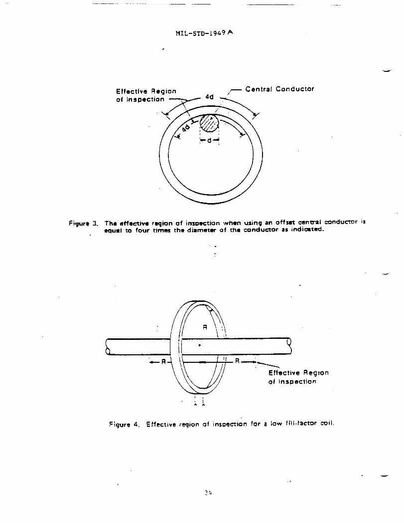
5.3.1.3.2 Offset central conductor, When the conductor passing throughthe inside of the part is placed against an inside wall of the part, thecurrent levels as given in paragraph 5.3.1.2 (“Direct circular magnetlzatlon”)shall apply except that the diameter shall be considered the sum of thediameter of the central conductor and twice the wall thickness. The distance
12

MIL-STD-1949A
along the part circumference (interior or exterior) which is effectivelymagnetized shall be taken as four times the diameter of the central conductor—as illustrated in figure 3. The entire circumference shall be inspected byrotating the part on the conductor, allowing for approximately a 10 percentmagnetic field overlap.
5.3.1.4 Longitudinal magnetization using coils. Longitudinalmagnetization is often accomplished by passing current through a coilencircling the part~ or Section of the part, to be tested (i.e. by using a“coil shotm). This produces a magnetic field parallel to the axis of thecoil. For low or intermediate fill factor coils the effective field extends adistance on either side of the coil center approximately equal to the radiusof the coil(see figure 4). For cable wrap or high fill factor coils, theeffective distance of magnetization is 230’mm (9 inches) on either side of thecoil center (see figure 5). For parts longer than theee effective distances,the entire length shall be inspected by repositioning the part within thecoil, allowing for approximately 10 percent effective magnetic field overlap.
5.3.1.4.1 Longitudinal magnetization with low fill factor coils. Whenthe cross sectional area of the coil is 10 or more times the cross sectionalarea of the part being inspected, then the product of the number of coilturns, N, and the current in amperes through the coil, I, shall be’:
a. For parts positioned to the side of the coil;
\
N1.K (: 10 %)L/D
where K = 45,000 ampere turnsL = length of the PartD = diameter of the part (measured
in the same units as the length)
b. For parts positioned in the center of the coil:
NI = KR (~lo %)(6L/D) - 5
where R = radius of the coil in ~ (or in inches)K . 1690 ampere turns per ~ (43,000 ampere turns per inch if
R is measured in inches)L = the length of the partD = the diameter of the part (measured
in the same units as the length)
If the part has hollow portions replace D with Deff as given inParagraph 5.3.1.4.4. These formulas hold only if L/D is greater than 2 andless than 15. If L/D is less than 2, pole pieces (pieces of ferromagneticmaterial with the same diameter as the p’artbeing tested) shall be placed oneach end of the part to effectively increase L/D to 2 or greater. If L/D isgreater than 15, the value 15 shall be substituted for IJ/D.
13
——
MXL-STD-1949A
5.3.1.4.2 Longitudinal magnetization with cable wrap or high fill factorcoils. When the cross sectional area of the coil is less than twice the crosssectional area (including hollow portions) of the part under test, then the -product of the number of coil turns, N, and the current in amperes through thecoil, 1, shall be:
NI m K(L/D)+2
(~lo %)
where K = 35,000 ampere turnsL = the length of the partD = the diameter of the part (measured
in the same units as the length)
If the part has hollow portions replace D with Deff as given inParagraph 5.3.1.4.4. This formula holds only if L/D is greater than 2 andless than 15. If L/D is less than 2, pole pieces (pieces of ferromagneticmaterial with the same diameter as the part being tested) shall be placed oneach end of the part to effectively increase L/D to greater than 2. If L/D isgreater than 15, the value 15 shall be substituted for L/D.
5.3.1.4.3 Longitudinal-magnetization for intermediate fill factor coils.When the cross sectional area of the coil is between two times and ten timesthe cross sectional area of the part being inspected, the product of thenumber of coil turns, N, and the current through the coil) It shall be:
where
NI
(NI
(NI
-r
= (NI)h~+ (NI)e.E28 8
.
e = the value of NI calculated for low fill factor coilsusing 5.3.1.4.1
h = the value of .NIcalculated for high fill factor COliSusing 5.3.1.4.2
z the ratio of cross sectional area of the coil to thecross section area of the part. (For example, if thecoil is 10 inches in diameter and the part is a rod5 inches in diameter Y = (7 . 52) /(~. 2.52) = 4.)
5.3.1.4.4 Calculating the L/D ratio for a hollow or cylindrical part.When calculating the L/lJratio for a hollow or cylindrical part, D shall Dereplaced with an effective diameter, Deff, calculated using:
Deff = 2 [(At - Ah) /’#2
where At = the total cross sectional area of the partAh = the cross sectional area of the hollow
portions of the part
14

MIL-STD-1949A
For cyi.indricalpart this is equivalent to:
.—‘eff - [ (OD)2 - (ID)2 )1/2
where OD = the outside diameter of the cylinder.ID E the inside diameter of the cylinder.
5.4 Particle application.
5.4.1 Continuous method. In the dry continuous method, magneticparticles are applied to the part while the magnetizing force is present. Inthe wet continuous method the magnetizing current shall be appliedsimultaneously with or immediately after diverting suspension from the part.Application of the magnetic particles (see 5.4.4 and 5.4.5) and themagnetization method shall be as prescribed in the paragraphs referencedherein.
5.4.2 Residual magnetization method. In the residual magnetizationmethod the magnetic particles are applied to the test part after themagnetizing force has been discontinued. The residual method is not assensitive as the continuous method but it can be useful~ for example, todetect in-service induced fatigue cracks on the surface of material with ahigh retentivity or as an interpretation aid. It is aleo useful for -
“ inspection of parts in areas where.,because”of geometric constraints thecontinuous method cannot be used. The residual method shall be used only whenspecifically approved by the contracting agency or when it has been documentedthat it can detect known or artificial defects in test parts. The test partsshall have the same material and processing steps as, and similar geometry to?the actual parts being inspected.
5.4.3 Prolonged magnetization. When using polymers, slurries, or paints,prolonged or repeated periods of magnetization are necessary because of lowermagnetic particle mobility in the high-viscosity vehicles.
5.4.4 Dry magnetic particle application. When using dry particles the flowof magnetizing current shall be initiated prior to the application of themagnetic particles to the surfaae under test and t-ar.minaLedafter powderapplication has been completed and any excess blown off. The duration of themagnetizing current shall be at least 1/2 second and short enough to preventany damage to the part due to overheating or other causes. Dry powder shallbe applied in a manner such that a light, uniform dust-like coating settles onthe surface of the test part while the part is being magnetized. Speciallydesigned powder blowers or shakers using compressed air or hand power shall beused. The applicators shall introduce the particles into the air in a mannersuch that they reach the part surface in a uniform cloud with a minimum offorce. Mter the powder is applied, and before the magnetizing force isremoved, excess powder shall be removed by means of a dry air current withsufficient force to remove the excess particles, but not strong enough todisturb particles held by a leakage field that is indicative ofdiscontinuities. In order to recognize the broad, fuzzy, lightly held powderpatterns formed by near surface discontinuities, the formation of indicationsmust be carefully observed during powder application and during removal of theexcess powder. Sufficient time for formation and examination of indicationsshall be allowed during the testing process. The dry particle method shallnot be used to inspect aerospace components (flight hardware) without specificapproval of the contracting agency.
15

MIL-STD”1949A
5.4.5 Wet magnetic particle application. Fluorescent or nonfluorescentparticles suspended in a liquid vehicle at the required concentration shall beapplied either by gently spraying or flowing the suspension over the area tobe inspected. Proper sequencing and timing of part magnetization andapplication of particle suspension are required to obtain proper formation andretention of indications. This generally requires that the stream ofsuspension be diverted from the part simultaneously with, or slightly before,energizing the magnetic circuit. The magnetizing current shall be applied fora duration of at least 1/2 second for each application with a minimum of twoshots being used. The second shot should follow the first in rapidsuccession. It should come after the flow of suspenalon has been interrupted,and should occur before the part is examined for indications. Under specialcircumstances, such as the use of automated equipment and\or for criticalparts, the 1/2 second duration and/or the 2 shot requirement may be waivedprovided it is demonstrated that the test procedure can detect known defectsin representative test parts (see 5.3a). Care shall be exercised to preventany damage to the part due to overheating or other causea. Weakly heldindications on highly finished parts are readily washed away and hence caremust be exercised to prevent high-velocity flow over critical surfaces.
5.4.6 Magnetic slurry/paint application. Magnetic paints or slurries areapplied to the part with a brush, squeeze bottle or aerosol can before orduring the magnetization operation. This method is for special applications,such as overhead or underwater examination. This method shall be used onlywhen specifically approv~d by the contracting agency.
5.4.7 Magnetic polymer application. Polymerizable material containingmagnetic particles shall be held in contact with the test part during theperiod of its cure. Before curing takes place and while the magneticparticles are still mobile, the part shall be magnetized to the specifiedlevel. This requires prolonged or rep”eatedperiods of magnetization. Thismethod is for special applications, such as bolt holes, which cannot bereadily tested by the wet or dry method and shall be used only whenspecifically approved by the contracting agency. MIL-I-83387 established the.inspection process for magnetic rubber.
5.5 Recordinq of indications. When required by the written procedure,the location of all rejectable indications shall be marked on the part andpermanent records of the location, direction and frequency of indications maybe made by one or more of the following methods.
5.5.1 Written description. By recording the locationt length~ direction~and number of indications by a sketch or in a tabular form.
5.5.2 Transparent tape. For dry particle indications, by applyingtransparent adhesive-backed tape to which the indications will adhere andplacing it on an approved form along with information giving its location onthe part.
5.5.3 Strippable film. By covering the indication with a spray-onstrippable film that fixes the indications in place and placing the resultantreproduction on an approved form along with information giving its location onthe part.
16

MIL-STD-1949A
5.5.4 Photography. By photographing or video recording the indicationsthemselves, the tape, or the strippable film reproduction and placing the----photograph on a tabular form along with information giving its location on thepart.
5.6 Post-inspection demagnetization and cleaninq. Unless directedotherwise by the contracting agencyt all parts shall be demagnetized, cleaned,and corrosion protected after final magnetic purti”cleinspection.
5.6.1 Demagnetization. When using alternating current demagnetizationthe part shall be subjected to a field with a peak value greater than, and innearly the same direction as, the field used during inspection. Thisalternating current field is then gradually decreased to zero. When using analternating current demagnetizing coil~ a suggested procedure is to hold thepart about 30 cm (1 ft) in front of the coil and then move it slowly andsteadily through the coil and at least 90 cm (3 ft) beyond the end of thecoil. Repeat this proce88 as necessary. Rotate and tumble parts of complexconfiguration while passing through the field of the coil. When using directcurrent demagnetization, the initial field shall be higher than~ and in nearlythe same direction as, the” field reached during magnetization. The fieldshall then be reversed, decreased in magnitude, and the process repeated(cycled) until an acceptably low value of residual field is reached. Wheneverpossible parts which have been circularly magnetized shall be magnetized inthe longitudinal direction before being demagnetized. After demagnetizationa magnetic field meter shall not detect fields with an abaoluke value greaterthan 240 Am-l (3 gauss) anywhere on the part.
— 5.6.2 Post-inspection cleaninq. Cleaning ehall be by use of a suitablesolvent, air blower, or by other means. Parts shall be inspected to ensurethat the cleaning procedure has removed magnetic particle residues fromcoolant holes, crevices, passage ways, etc., since such residues could have anadverse effect on the intended use of the part. Care shall be taken to removeall plugs, masking or other processing aids that may affect the intended useof the part. Parts shall be protected from any possible corrosion or damageduring the cleaning process and shall be treatedcorrosion after final inspection.
5.7 Quality control.
5.7.1 System performance verification. The
to prevent the occurrence of
overall performance of themagnetic particle inspection system including the equipment, materials and thelighting environment being used, shall be verified initially and at regularintervals thereafter. The required verification intervals are stated in tableII. Records of the verification results shall be maintained. Current andvoltage measuring devices, ammeter shunts, timers, and gaussmeters used in theverification shall comply with the requirements of MXL-STD-45662.
5.7.2 Use of test part with discontinuities. A reliable method forinspection system verification is the use of representative test partscontaining defects of the type, location, and size specified in the acceptancerequirements. If magnetic particle indications can be produced and identifiedin these representative parts, then the overall system performance is verified.Parts used for verification will be demagnetized and thoroughly cleanedfollowing the inspection and checked under black or white light, as appropriateto the inspection process, to ensure residual indications do not remain.
17

MIL-STD-1949A
5.7.3 Fabricated test parts with artificial discontinuities. When actualproduction parts with known defects of the type, location and fiizeneeded foLverification, are not available or are impractical, then, fabricated testparts with artificial defects shall be used. Artificial defects may be -
fabricated to meet a particular need or may be commercially available magneticfield indicators shown in figures 6 and 7 or the Ketos ring aa defined infigure 1. All applicable conditions for the use of such test parts, asdescribed in 5.7.2, shall apply.
5.7.4 Suspension vehicle tests. (Not required for aerosol can solutions)
5.7.4.1 Concentration tests. Particle concentration and contaminationshall be determined upon start up~ at regular intervals thereafter, andwhenever the bath is changed or adjusted. The required testing intervals arestated in table II.
S.7.4.1.1 Determination of wet particle concentration. Agitate theparticle suspension a minimum of 30 minutes to insure a uniform distributionof particles throughout the bath. Place a 100 ml sample of the agitatedsuspension in a pear-shaped centrifuge tube (of the size and shape specifiedin ASTM D96, except graduated to 1 ml in 0.05 ml increments). Demagnetize thesample and allow the tube to stand undisturbed for at least 60 minutes ifusing the petroleum distillate specified in AM 2641 or 30 minutes settlingtime for conditioned water suspension. Read the volume of settled particles.If the concentration is out of the tolerance stated in the written procedure(or that given in paragraph 4.9.3) add particles or suspension vehicle, asrequired, and redetermine the particle concentration. If the settledparticles appear to be loose agglomerates rather than a solid layer, take asecond sample. If the second sample also appears agglomerated, replace theentire suspension. Thirty minute settling timesl or other accelerated tests,may be used if they have been verified to give results equivalent to theprocedure described in this paragraph.
5.7.4.1.2 Determination of wet particle contamination. Perform thetests specified in paragraph 5.7.4.1.1. In addition, for fluorescent baths,examine the liquid directly above the precipitate with black light. Theliquid shall be essentially nonfluorescent. Examine the graduated portion ofthe tube both under black light (for Fluorescent baths only) and under visiblelight (for both fluorescent and nonfluorescent baths) for striations or bands,different in color or appearance. Bands or striations may indicatecontamination. If the total volume of the contaminates, including bands orstriations, exceeds 30% of the volume of magnetic particles, or if the liquidis noticeably fluorescent, the bath shall be replaced.
5.7.4.2 Water break test. In this test of water based vehicles a cleanpart with a surface finish the same as the parts to be tested is flooded withthe conditioned water and the appearance of the surface is noted afterflooding is stopped. If a continuous even film forms over the entire part,sufficient wetting agent is present. If the film of suspension breaks,exposing bare aurfecet insufficient wetting agent is present or the part hasnot been adequately cleaned.
-
18

5.7.5be checked-.thereafter
MIL-STD-1949A
EquipmenL calibration. Magnetic particle testing equipment shallfor performance and accuracy at time of purchase and at intervalsas given in table 111 whenever malfunction is suspected or when .
specified by the contracting agency, and whenever electrical maintenance whichmight affect equipment accuracy is performed.
5.7.5.1 Ammeter accuracy. To check the equipment ammeter, a calibratedammeter shall be connected in series with the output circuit. Comparativereadings shall be taken at three output levels encompassing the useable rangeof the equipment. The equipment meter reading shall not deviate by more than+1O percent of full scale from the current value shown by the calibratedammeter (when measuring half wave rectified alternating current~ the currentvalues shown by the calibrated direct current ammeter reading shall bedoubled). The ammeter should be checked according to the time frame indicatedin table II.
S.7.5.2 Timer control check. On equipment using a timer to controlcurrent duration, the timer should be checked to within ~0.1 second using asuitable electronic timer.
S.7.5.3 Magnetic field quick break check. On equipment which utilizes aquick-break featurej proper functioning of this circuit shall be verified.The test may be performed using a suitable oscilloscope or other applicablemethod as specified by the equipment manufacturer.
5.7.5.4 Dead weight check. Yokes and permanent magnets (when allowed)shall be dead weight tested at intervals as stated in table II. Alternating
-- current yokes shall have a lifting force of at least 45 N (10 pounds) with a50 to 100 mm (2 to 4 inch) spacing between legs. Direct current yokes shallhave a lifting force of at least 135 N (30”~unds) with a 50 to 100 mm (2 to 4inch) spacing between legs or 225 N (50 pounds) with a 100 to 150 mm (4 to 6inch) spacing.
5.8 Marking of inspected parts. Unless otherwise specified by thecontracting agency, parts which have been accepted using magnetic particleinspection shall be marked in accordance with the applicable drawing, purchaseorder, contract or ae specified herein. Marking shall be applied “in such amanner and location as to be harmless to the part. The identification shallnot be obliterated or smeared by subsequent handling andt when practicable,shall be placed in a location which will be visible after assembly. Whensubsequent processing would remove the identification, the applicable markingshall be affixed to the record accompanying the finished parts or assembly.Bolts and nuts and other fastener products may be identified as having met therequirements of magnetic particle inspection by conspicuously marking eachpackage.
5.8.1 Impression stamping, laser marking, or vibro engravinq. Impressionstamping, laser marking~ or vibro engraving shall be used when permitted orrequired by the applicable written procedure~ detail specification or drawing,or when the nature of the part is such as to provide for impression Stampingof part numbers or other inspector’s markings. Impression stamping shall belocated only in the area provided adjacent to the part number or inspector’sstamp unless otherwise specified by the contracting agency.
19

— -— —..
MIL-STD-1949A
5.8.2 Etchinq. When impression stamping or vibro engraving isprohibited, parts shall be etched using an etching fluid OK other means and amethod of application acceptable to the contractor. The etching process andlocation shall not adversely affect the functioning of the part. -
5.8.3 Dyeinq. When stamping, vibro engraving or etching is notpermissible, identification shall be accomplished by dyeing.
5.8.4 Other identification. Other means of identification such astagging, shall be used for parts which have a construction or functionprecluding the use of stamping, laser marking~ vibro engraving or etching, asin the case of completely ground or polished balls, rollers, pins, or bushings.
5.8.5 Identifying symbols and color markings.
5.8,5,1 lC)O-percentinspection. When items are inspected and accepted by100-percent inspection, each item shall be marked as follows:
5.8.5.1.1 Dyeinq. When dyeing is applicable, a dye of acceptableadherence which is predominately blue (per FED-STD-595) shall be employed.HOWeV@r, if a color c’onflictis incurred with any other method, magneticparticle inspection can be indicated by two adjacent blue dots or othersuitable means.
5.8.5.1.2 Stamping, laser marking, vibro engraving or etching. Whenimpression stamping~ laser marking~ vibro engraving or etching is used tomark 100-percent inspected parts, the letter ‘M” with a circle around it shallbe employed.
5.8.5.2 Lot inspection. When items are accepted by means of a samplingprocedure, each item of an accepted lot shall be marked as follows:
5.8.5.2.1 Dyeinq. When dyeing is applicable, a dye of acceptableadherence which is predominately orange per FED-STD-595 shall be employed.
5.8.5.2.2 Stamping,vibro engraving or etching. When impression stamping,laser marking, vibro engraving or etching is used to mark lot-inspected parts,the letter “Mm shall be employed.
5.9 Eye glasses. When using fluorescent materials, inspectors shall notwear eye glasses permanently tinted or equipped with light restrictive orlight sensitive lenses (i.e. lenses that darken when exposed to ultravioletlight or sunlight). This is not intended to prohibit the use of eyeglasseswith lenses treated to absorb W light.
5.10 Aircraft quality steel cleanliness. The inspection ofaircraft-quality steel for cleanliness using magnetic particle inspectionshall be as specified in APE 2300, AMS 2301, or AM 2303 as appropriate to thetype of steel being inspected. However, inspection of parts fabricated fromthis material shall be in accordance with the requirements of this document.
5.11 Acceptance r’equirements. Methods for establishing acceptancerequirements for large crankshaft forgings are discussed in ASTM A456.
20

MIL-sTD-1949A
Methods for establishing requirements for steel forgings areASTM A275. Methods for classifying metal caating8 are given
-- MIL-M-350 provides a classification scheme for ferromagneticcasting8* extrusions and weldments.
discussed inin MIL-STD-21?5.forgings,
5.12 Safety. Safe handling of magnetic particles (wet or dry)? oilvehicles water baths, and water conditioner concentrates are governed by thesuppliers’ Material Safety Data Sheets (MSDS). Material Safety Data Sheets,conforming to 29 CPR 1910.1200, or equivalent, must be provided by thesupplier to any user and shall be prepared in accordance with FED-STD-313.
5.12.1 Flammability. Flash point of oil vehicles shall be in accordancewith AMS 2641 or DOD-F-87935. The suppliers’ MSDS shall certify the flashpoint.
5.12.2 Personnel hazards. Precautions against inhalation, skin contact;and eye exposure are detailed in the suppliers’ MSDS. These precautions shallbe observed.
5.12.3 Electrical hazards. Magnetizing equipment shall be properlymaintained to avoid personnel hazards from electrical short circuits. Caremust be taken to reduce arcing and possible ignition of oil bbths.
5.12.4 Black light. It is recommended that the intensity of black lightincident on unprotected skin or eyes not exceed 100~W/cm2. Cracked orbroken OV filters shall be immediately replaced. Broken bulbs can continue toradiate UV energy and must be replaced immediately. Spectacles designed toabsorb W wavelength radiation are suggested for close, high black light
--intensity inspection.
5.13 Dark adaptation. Personnel must wait at least one minute afterentering a darkened area for their eyes to adjust to the low level lightingbefore performing fluorescent magnetic particle inspection.
21
—
MIL-STD-1949A
6. NOTES
(This section contains information of a general or explanatory nature thatmay be helpful, but is not mandatory.) -
6.1 Measurement of tangential field strength. Care must be exercisedwhen measuring the tangential applied field strengths specified in paragraph5.3. The active area of the Hall-effect probe should be no larger than 5 mmby 5 mm and should have a maximum center location 5 mm from the part surface.The plane of the hall effect element must be perpendicular to the surface ofthe part at the location of measurement to within 5 degrees. This iSdifficult to accomplish by hand orientation and the probe should be held in ajig or fixture of some type. If the current is being applied in shots, or ifalternating current or half wave rectified alternating current is being used,the gaussmeter should be set to read the peak value during the shot. Thegaussmeter should have a freguency response of O to 300 Hz or higher. Thedirection and magnitude of the field can be determined by two measurementsmade at right angles. The gaussmeter probe leads should be shielded ortwisted to prevent reading errors due to voltage induced during the largefield changes encountered during magnetic particle inspection.
6.2 Subject term (key word) listing.
Magnetic particle testingNondestructive testing
Custodians:Army - MRNavy - ASAir Force - 11
Review activities:hrmy - AR, AV, EA, HINavy - SHAir Force - 99, 70, 80, 82, 24, 84
User activities:Army - Al’,AL, ME, TEr ARNavy - 0SAir Force - 71
Preparing Activity:Army - MR -
Project NDTI-0127
(WP# ID-0381A/DIsC-0136B. FOR MTL USE ONLY)
22

MI 1,-::’I’lL I’M’)A
3“ti\4
I I
125
5“
L
FIGURE 1.
,
0.070t 0.005tiokS ThroughTyp.
Notes: All Tolerances W. t 0.03” Except Where ShownHoi. Numbers 8-12 ●re Optlond
\ 1,
HO* 1 2 3 4 5 6 7 8 9 10 11 124
D, inch- .07 .14 .21 .28 .35 .42 .49 .56 .63 .70 .77 .84~ooo(J5
KETOS tool steel rinc for use in magnetic particle ‘yStemverification and testinR of magnetic particles. All dimensions ure
in inches. Haterinl shrillbe AIS1 01 tool steel from annealed roundstock. ][arc)noas shall be W-~S Rockwell ~“
,- Prlmwy
I
FICUHE 2. Example of induced current magnetization. The primary current 9et9
up an 06cillatintgrnmgneticfield. This primaqy magnetic field -
induces a current in the ring shaped part under’test.23
MIL-sTD-19f49 A
,
Elfective Region
Figur~ 3. Th. effectiva region of inspection when using an offset cmtral rxmducmr isequal to four rimes rho diameter of the conductor as indicated.
--
-R
‘~
\‘1 R-
.1Effective Ilegton
of Inspection
Figure4. Effective reqion of inspectionfor a low f~li-f=tor ~ii.
.

HIL-STD-1949A
,
,—
.
EffectIon RegionOf Inspection
,
FIGURE 5. Effective region of inspection for a high fill-factor coil
. .
r’- ~cetmu?iste,o.olo” *0.002”
1 #
-r[ ‘o
1n (
FIGURE 6. Pie-field indicator for ume in magnetic Particle inspectionsystem verification. All dimensions are in inches. Eight
low carbon steel Pie shaped sections are furnace braz~dtogether and coPpe r plated.
25

MIL-STD-1949A
20 mm
(0.75 in)
4
20 mm
I
Eli
k-kA
12.5 m(0.5 in)
0.05 mm(0.002 in)
+-b- 0.015 mm
(0.0006 in)
Section A-A
+ * 0.05 mm
I
(0.002 in)
i 0.125 mm
T“( 0.005 in)(typ.)
!I> A +* 0.015 mm
(0.0006 in)
Section A-A
Defect Divisional line~1-
0.05 mm
I I/l I I I II I 1 I I I 1 I ! B
+(0.002 in)
— 0.125 mm
T(0.005 in)
5 mm 4 +++- 0.015 mm
(0.0006 in)10 mm
F@ure 7. Examples of artificial flaw shims used in magneticparticle inspection system verification. (Not drawn toscale.) The shims are made of low carbon steel (e.g.1005 steel foil). The artificial flaw is etched ormachined on one side of the foil to a depth of 30percent of the foil thickness. In use, the shims arefirmly attached to the test part (e.g. with tape aroundthe edges) with the flaw towards the part.
26

HIL-STD-1949A
TABLE 1. Required indications when using the ringspecimen of figure 1.
.—
Particles Wed Central Conductor Minimum NumberFull Wave Recti- of Holes Indicatedfied AlternatingCurrent Amperage .
Wet suspension, 1400 3
fluorescent or 2500 5nonfluorescent 3400 6
Dry powder 1400 42500 63400 7
TABLE II. Required verification intervals.
MAXIMUM TIME REFERENCEITEM BETWEEN VERIFICATIONS PARAGRAPH
Lighting:Black light intensity 1 week 4.8.2Visible light intensity .1 week 4.8.1Background visible light intensity 1 week 4.8.1-
System performance using test 1 ● day 5.7piece or ring specimen of figure 1
Wet particle concentration . 8 hours, or 5.7.4.1.1every shift change
Water break test 1 day 5.7.4.2Wet particle contamination 1 week 5.7.4.1.2
Equipment calibration/check:Ammeter accuracy 6 months 5.7.5.1Timer control 6 months 5.7.5.2Quick break 6 months 5.7.5.3Dead weight check 6 months 5.7.5.4 “
Note: The maximum time between verifications may be extended whensubstantiated by actual technical stability/reliability data.
27

—
=ANDARDIZATION DOCUMENT IMPROVEMENT PROPOSAL
OOCUMINT NUMOS R 2. 00CUM8NT TITLR
MIL-STD-1949A Inspection, Magnetic Particleh NAMCOPSUSMl~lNO On* N$*TION
k AoDac*8fmd. my. mom. ZwCo&)
.
&
L TVM OF OnOANIZATION(M- OIU)u VENOOR
❑ USC n
•1 MANUPACTLMER
c1 OTHER (Gfy):
NAME Of SUBMITTEn (ko4Fht, w) - Opthnd b, WORK TE LEPHON6 NUM@ER (hChd4AmCo&) - Ootlond
..... ... !MAILINO AOORE- fhoa~ fWY, Stern, ZIP Colt) - Ootbrui S. OATE OF SUBMISSION (YYMMDD)