military handbook - mil-std-188everyspec.com/mil-hdbk/mil-hdbk-1000-1299/download... · submarine...
TRANSCRIPT

e
I
rmAim3K-low !231 ~ RC!i1984SUPERSEDINGDM-4.2DECEMBER 1979
MILITARY HANDBOOK
POWER DISTRIB~ION SYST~
I
pISTNmTIOfl STATEKENT $,. APPROWD FOR I?U5LSCRELEASE: DISTRI$Wl~N IS
UNLIMTED
Mw% IM:R
Downloaded from http://www.everyspec.com

o rm#-mFK-loo4/2
ABSTRACT
This handbook covers design criteria for elect:ic power distributionsystems including basic data, overhead and underground distribution systems,submarine cable systems, and substations. The basic design guidance has beendeveloped,from extensive reevaluation of facilities and is intended for use byexperienced architects and en~ineers.
I
eI
Downloaded from http://www.everyspec.com
‘o MIL-HDBK-1OOW 2
FOEEWORD
This handbook has been developed from an evalwatio~ of facilities in the shoreestablishment, from knarveye of the availability of mew materials andconstriction methods, and from selection of the beat design practices of thel?avaS.Facilities Engineering Command (kAVFACENGCOM), other Governmentagencies, an~ the private $?eccor. This handbook was prepared using, to the
maximum extent feasible? national professional society, association, andInstitute standards. Deviations from this crfter~a, in the phnnhg,engineering, design$ and construction of Naval shore facilities, cannot bemade without prior approval of NAVFACENGCOM i3QCode 04.
Design cannot remain static any more than can the functions it serves or thetechnologies it uses. Accordingly, recommendations for improvement areencouraged and 6hould be furnished to Commander, ?acific Division, NavalFacilities Engfneexing Command (Code 406), Pearl Harbor, HI 96860-7300;Telephone (808) 471-8436.
THIS HANDBOOK SHALL ROZ’BE WED AS A REFERENCE DOCUMENT FOR PROCUREMENT OFFACILITIES CONSTRUCTION. IX 1S TO BE USED IN THE PURCEASE Or FACILITIESENGTNEEIHI?GSTUDIES AND DESIGN (FIHAL FLMS, SPECIFICATIONS, AND COSTwIm4AzEs)’. Ml WIT REFERENCE IT IN MILHAEY OR FEDERAL SPECIFICATIONS OROTHER ‘PROCUREMENTDOCUMENTS.
Downloaded from http://www.everyspec.com

Criteria
Manual
DM-4 .1
MIL-HDBK-1004/2
KIL-HDBK-loo4/3
MIL-HDBK-loo4/4
DM-4 .05
DM-4 .6
DM-4 .07
DM-4 .09
MIL-HDBK-loo4/lo
mIL-HDBK-Loo4/2
ELECTRICAL ENGINEERING CRITERIA MANUALS
Preliminary Design Considerations
Power Distribution Systems
Switchgear and Relaying
Electrical Utilization Systems
400-Hertz Medium-Voltage Conversion/
Distribution and Low-Voltage Utilization
Sys t ems
Lightning (and Cathodic) Protection
Wire Communication and Signal Systems
Energy Monitoring and Control Systems
Cathodic Protection (proposed)
lx
CHZSDIV
PACDIV
CHESDIV
CHESDIV
CHESDIV
CHISDIV
CKSSDIV
HDQTRS o
NCEL
NOTE : Design manuals, when revised, will be converted to military handbooks.
This handbook is issued to provide immediate guidance to the user.
However, it may or may not conform to format requirements of
MIL-HDBK-1006/3 and will be corrected on the next update.
I
L. .— -— —-IL -—
Downloaded from http://www.everyspec.com
!0 MIL-HDBK-1004/2
POWER DISTRIBUTION SYSTEMS
Comms
I
o
Section 11.11.21.31.3.11.3.21.3.31.3.41.3.51.41.4.11.4.21*4.33.s1.61.7
Section 22.12.1.12.1.22.1.32.1.42.22.2.32.2.1.22.2.1.32.2.3.42.2.1.52.2.1.62.2.1.72.2.22.2.2.12.2.2.22.2.32.2.3.12.2.3.22.2.3.32.2.3.42.2.3.52.2.3.62.2.42.2,4.12.2.4.2
INTRODUCTIONScope ......● ● ......● ..***.*● ****.● ..=● ● ● .● **● *● **● ● *● **Cancellation ...........................................Technical Factors ........................**............Feeders .*.*....● .● ● ... ● .*......● .*....*.......*...*....Current (Ampere) Levels and Mterrupting Dutie6 ........Equipment Requirements ..*,........**.............**....Weather Extremes ......................... ..............Lecal Codes ...**..● ....*,....................● .....,● ..EconomicFactors .......................................Number of Circuits ..............*........*.............Voltage ................................e........o.a=a.mTransformer Losses ................w....w+.w.-..........Special Construction ......................O............Shore-TcAlhip D%str%but$on System . . . . . . . . . . . . . . . . . . . . .Good Practice ..........................................
OVERHEAD DXSTRIWTIO1’1SYSTEMSCircuiz Design ......● ..● .*.*....*........● ....,.,...● ..Application ..................... .......................Capacity ...............................................Wire Size .*● *.,.● .....*.● *● .*.**.....,...*● ● *..........Physical I’eaWres ......................................Line Materials ........*...*......*.0...................Poles ......................,.*............*.*.*...● ...*Heights and Classes ....................*...”............Strength %equiremmts .......................*..........Safety Factors ...*...*......*.*.*.****● ● *● .● ● ● ● ● **..● **Pole Installation ...........................=.........sConfiguration ..........................-...............Croasarm .........................*..........-V9=..-=.=Gu&F&and Anchors ....● .● o.*.**********● ● .**V*Q● ***● *● **●
Safety Requirements .*....*.*...............*.....**.,*.Design of Earth bchors ...............0...-.”.”.”......Conductors ................O.O........ ............-.OOO.S%ze Lisiitat$ons..................+....WD90............Normal Priman Limes ...................................Tropical and Semitropical Locations .....*,● .....4.*....Special Primary Line ....................*...... ........Utiliz&tion Limea ......................................Dissimilar Conductor Connections .......................Insulators ......● *..........● ...0.*.● ● o...-*.*...*● *● *.Insulator Combinations .........,.● .........● *.0..**● ● ***Dimensions and.Loads ........,.,,...,....................
vii
Downloaded from http://www.everyspec.com

MIL-fiDBK-1004/2 “o
Ec?.s
2 .2.4.3
2 .2.5
2.3
2.3.1
2.3.2
2.4
2.4.1
2.4.2
2.4.3
2.4.4
2.4.5
2,4.6
2.5
2.5.1
2.5.2
2,5.3
2.5.4
2.5.5
2.5.6
2.6
2.6.1
2.6.2
2.7
2.7.1
2.7.2
2.8
2.8.1
2.8.2
2.8.3
2.8.4
2.8.4.1
2 .8.4.2
2.8.4.3
2.8.4.4
2.8.5
2.8.6
2.9
2.10
2.10.1
2.10.2
Section 3
3.1
3.2
3.2.1
3.2.2
3.2.2.1
3.2.2.2
3.3
3.3.1
3.3.1.1
3.3.1.2
Insulation Levels . . . . . . . . . . . . . . . . . . . . . . . . . . . . . . . . . . . . . .
Hardware . . . . . . . . . . . . . . . . . . . . . . . . . . . . . . . . . . . . . . . . . . . . . . .
Line Equipment . . . . . . . . . . . . . . . . . . . . . . . . . . . . . . . . . . . . . . . .
Step-Voltage Regulators . . . . . . . . . . . . . . . . . . . . . . . . . . . . . . . .
Capacitors . . . . . . . . . . . . . . . . . . . . . . . . . . . . . . . . . . . . . . . . . . . . .
Transformers . . . . . . . . . . . . . . . . . . . . . . . . . . . . . . . . . . . . . . . . . . .
Pole Mounting . . . . . . . . . . . . . . . . . . . . . . . . . . . . . . . . . . . . . ...!.
At-Grade Mounting . . . . . . . . . . . . . . . . . . . . . . . . . . . . . . . . . . . . . .
Indoor Installation . . . . . . . . . . . . . . . . . . . . . . . . . . . . . . . . . . . .
Overload Capacity . . . . . . . . . . . . . . . . . . . . . . . . . . . . . . . . . . . . . .
Transformer Noise Level . . . . . . . . . . . . . . . . . . . . . . . . . . . . . . . .
Overhead Distribution . . . . . . . . . . . . . . . . . . . . . . . . . . . . . . . . . .
Circuit Interrupting Devices . . . . . . . . . . . . . . . . . . . . . . . . . . .
Puses , . . . . . . . . . . . . . . . . . . . . . . . . . . . . . . . . . . . . . . . . . . . . . . . . .
Current Limiting Protectors . . . . . . . . . . . . . . . . . . . . . . . . . . . .
Circuit Breakers . . . . . . . . . . . . . . . . . . . . . . . . . . . . . . . . . . . . . . .
Automat icCircuit Reclosers . . . . . . . . . . . . . . . . . . . . . . . . . . . .
Nonload-Break Switches . . . . . . . . . . . . . . . . . . . . . . . . . . . . . . . . .
Load-Break Switches . . . . . . . . . . . . . . . . . . . . . . . . . . . . . . . . . . . .
Lightning Protection . . . . . . . . . . . . . . . . . . . . . . . . . . . . . . . . . . .
Requirements . . . . . . . . . . . . . . . . . . . . . ...!..... . . . . . . . . . . . . .
Application . . . . . . . . . . . . . . . . . . . . . . . . . . . . . . . . . . . . . . . . . . . .
Clearances . . . . . . . . . . . . . . . . . . . . . . . . . . . . . . . . . . . . . . . . . . . . .
Contingency Interferences . . . . . . . . . . . . . . . . . . . . . . . . . . . . . .
Multipurpose Conditions . . . . . . . . . . . . . . . . . . . . . . . . . . . . . . . .
Grounding . . . . . . . . . . . . . . . . . . . . . . . . . . . . . . . . . . . . . . . . . . . . . .
Safety . . . . . . . . . . . . . . . . . . . . . . . . . . . . . . . . . . . . . . . . . . . . . . . . .
Ground Resistance Path . . . . . . . . . . . . . . . . . . . . . . . . . . . . . . . . .
Maximum Ground Resistance . . . . . . . . . . . . . . . . . . . . . . . . . . . . . .
Grounding Methods . . . . . . . . . . . . . . . . . . . . . . . . . . . . . . . . . . . . . .
Ground Rods . . . . . . . . . . . . . . . . . . . . . . . . . . . . . . . . . .. . . . . . . . . .
Water Pipe Connections . . . . . . . . . . . . . . . . . . . . . . . . . . . . . . . . .
Combination of Grounding Methods . . . . . . . . . . . . . . . . . . . . . . .
Ground Connections . . . . . . . . . . . . . . . . . . . . . . . . . . . . . . . . . . . . .
Overhead Ground Wires . . . . . . . . . . . . . . . . . . . . . . . . . . . . . . . . .
Measurement of Ground Resistance . . . . . . . . . . . . . . . . . . . . . . .
Service Drop to Buildings . . . . . . . . . . . . . . . . . . . . . . . . . . . . . .
Right-of-Way . . . . . . . . . . .. . . . . . . . . . . . . . . . . . . . . . . . . . . . . . . .
Widths . . . . . . . . . . . . . . . . . . . . . . . . . . . . . . . . . . . . . . . . . . . . . . . . .
Trees . . . . . . . . . . . . . . . . . . . . . . . . . . . . . . . . . . . . . . . . . . . . . . . . . .
UN!3ERGROUK0 DISTRIBUTION SYSTEMS
Circuit Design . . . . . . . . . . . . . . . . . . . . . . . . . . . . . . . . . . . . . . . . .
Direct Burial . . . . . . . . . . . . . . . . . . . . . . . . . . . . . . . . . . . . . . . . . .
Protection . . . . . . . . . . . . . . . . . . . . . . . . . . . . . . . . . . . . . . . . . . . . .
Installation . . . . . . . . . . . . . . . . . . . . . . . . . . . . . . . . . . . . . . . . . . .
Trench Dimensions . . . . . . . . . . . . . . . . . . . . . . . . . . . . . . . . . . . . . .
Cable Protection . . . . . . . . . . . . . . . . . . . . . . . . . . . . . . . . . . . . . . .
Draw-In Systems . . . . . . . . . . . . . . . . . . . . . . . . . . . . . . . . . . . . . . . .
Duct Lines . . . . . . . . . . . . . . . . . . . . . . . . . . . . . . . . . . . . . . . . . . . . .
Routes . . . . . . . . . . . . . . . . . . . . . . . . . . . . . . . . . . . . . . . . . . . . . ...!
Multipurpose Conditions . . . . . . . . . . . . . . . . . . . . . . . . . . . . . . . .
89
9
9
s
10
10
10
10
10
10
10
11
11
11
11
11
11
11
:; ●12
12
11
12
12
12
12
13
13
13
13
13
13
13
14
14
14
14
15
15
15
E ●15
15
15
15
Downloaded from http://www.everyspec.com
‘o MIL-HW3K-1OCW 2
‘eI
3.3.1.3’3’.3.1.43’.3.1.s3.3.1.63.3.1.73.3.1.83.3.23.3.2.13.3.2.23.3.2.33.3.2.43.3.2.53.3.2.63.3.2.73.43.4.13.4.1.13.4.1.23.4.23.4.2.13.4.2.23.4.2.33’.4.33.4.3,13.4.3.23.4.43.4.4.13.4,4.23.4.4.33.4.4.43.4.4.53.4.4.63.4.4.73’.4.4.83.4.53.4.5.13.4.5’.23.4.63*4*73.4.03.4.93.4.103.4.113.4.11.13.4.11.23.4.11.32.s3.5’.13.5.13.5.23.62.7
Clearance ..............................................Materials ...........,.*● ● ....*...,..#......*● .● ● .● ***..size Qf Ducts .......,..........*....● .....● ............Arrangement of Duct B-.. ............................Drainage ......................... .....................Spare Capacity *.0..*● ..*● *..,● .*...**..*........● ,● *...Manholes and Handhc?les.......... ........● .● ...● *● **● ***selection ...........................*...*..***.....*=**Location ..............................................=Use ,**.,.**......***...● ..*.● ● **.*..........,...,● ...,.Construction of Manholes ...*.**.*.● .● ...● *...*.........Comstmction of Hantioles ......................... .....Stubs ..................................................Hardware .....................................O..@ow..DOtlndergrowndCables .,..................● ........*......*sin@e- or Multiple-Conductor Cables ...................Si~le-Conductor Cables ...v.........*.*.● **....*......*Multiple-Conductor Cables .................*............Conductor ?laterials.........................+..........Annealed Copper ........................................Fledium-Hard-Dram Copper ....,...*.● ..........*........*Aluminum ....*........● .......,...*.............**......Preferred Cable Insulations ............................Advantages .....*..*...**..**.*● ● ..0**● ● ● ● ***● ● ● .**● ● **.Disadvantages ..........................................Other Insulations ......................................Polyvinyl-Chloride ........,...w.● *● ● .. .,.....*.........Polyethylene ........................*..................Butyl-Rubber .● .***.● ....*.....**....● .*.*...*.*..0● ● ● ..Silicone-Rubber ... ........● ● ...● ● **..*O● .Q.● *■ ● *******●
Mineral-Insulated Cable ......● .● *.● ......**.....**..**.Rubber ...........................................s..=s=Vamished-(hmbric .........................-............Paper-Insulated ..*.*..● ........**....● .....*.● ● ..*....*Cable Sheaths ......................**..*.............● .?kmwtallic ,..*...● .....*...........**.................lletallic.,*.● ● .,● ....● ...*● **.......*..*........*......Cable Coverings ...................................=..+*Shielded Cables ...*.......***● ..*.,...● .● .**● *..● ● **.● ●
Cable Splicing ● *.....● **.● .............*.*.****........Cable Ilreproofin& .*..**.● **,....● ....*.................Cable Identification ..**.***● *● *....● .*.*o.**...● ......Gas Preasur%ze& Gable ..................................SF6 Gas ● *.............-..........● ......*..,......*● *Installation ............................ ................Optional Usage .........................- ...............UndergroundTransfomers .......................*.......Equipment ,....*..● ...,.. .........● .....*.● ,,***.......*Equipment ...*.● ......*,.*.*.....*...● ....,.● ....,..,.....Vaul,cDesign *.● ....● .....*...*****● *..● ● ..● @.0..● ....*..Cable Ampacit.y...● *● .....*..........*..**.....*.*.....~●
Safety Considerations ..........● ..,,...*● ........● ..-.*.4
1616161616161616171717173717171919191919191919191’9191920202020202020202020202021212121212122 -2222222222~~
Downloaded from http://www.everyspec.com

MIL-HDBK-1004/2
Section 4
4.1
4.1.1
4.1.2
4.2
4.2.1
4.2.2
4.2.2.1
4.2.2.2
4.2.2.3
4.2.3
4.2.4
4.3
4.3.1
4.3.2
.4.3.3
4,3.4
4.3.5
4.4
4.4.1
4.4.2
4 .4,2.1
4.4.2.2
4.4.3
4.4.4
4.5
4.5.1
4.5.1.1
4.5.1.2
4.5.2
4.5.3
Section 5
5.1
5.1.1.1
5.1.1.2
5.1.2
5.1.3
5.2
5.2.1
5.2.1.1
5.2.1.2
5.2.1.3
5.2.2
5.2.2.1
5.2.2.2
5.2.2.3
5 .2.2.4
5 .2.2.5
5.2.2.6
5.2.3
5.2. 3.1
SUBMARINE CABLE SYSTEMS
Preliminary Considerations . . . . . . . . . . . . . . . . . . . . . . . . . . . . . .
W’iere Permitted . . . . . . . . . . . . . . . . . . . . . . . . . . . . . . . . . . . . . . . . .
Installation Problems . . . . . . . . . . . . . . . . . . . . . . . . . . . . . . . . . . .
Location Considerations . . . . . . . . . . . . . . . . . . . . . . . . . . . . . . . . .
Soundings . . . . . . . . . . . . . . . . . . . . . . . . . . . . . . . . . . . . . . . . . . . . . . .
Hydraulic Restrictions . . . . . . . . . . . . . . . . . . . . . . . . . . . . . . . . . .
Turbulences . . . . . . . . . . . . . . . . . . . . . . . . . . . . . . . . . . . . . . . . . . . . .
Current . . . . . . . . . . . . . . . . . . . . . . . . . . . . . . . . . . . . . . . . . . . . . . . . .
Variable (Changing )Waters . . . . . . . . . . . . . . . . . . . . . . . . . . . . . .
Chemical Composition of Waters . . . . . . . . . . . . . . . . . . . . . . . . . .
Marine Traffic . . . . . . . . . . . . . . . . . . . . . . . . . . . . . . . . . . . . . . . . . .
Installation . . . . . . . . . . . . . . . . . . . . . . . . . . . . . . . . . . . . . . . . . . . .
Burying Cable . . . . . . . . . . . . . . . . . . . . . . . . . . . . . . . . . . . . . . . . . . .
hchors . . . . . . . . . . . . . . . . . . . . . . . . . . . . . . . . . . . . . . . . . . . . . . . . -
warning signs . . . . . . . . . . . . . . . . . . . . . . . . . . . . . . . . . . . . . . . . . . .
Pile Clusters . . . . . . . . . . . . . . . . . . . . . . . . . . . . . . . . . . . . . . . . . . .
MSPS . . . . . . . . . . . . . . . . . . . . . . . . . . . . . . . . . . . . . . . . . . . . . . . . . . . .
Cable Types . . . . . . . . . . . . . . . . . . . . . . . . . . . . . . . . . . . . . . . . . . . . .
Metallic-Sheathed Cable . . . . . . . . . . . . . . . . . . . . . . . . . . . . . . . . .
Armored Cable, Application . . . . . . . . . . . . . . . . . . . . . . . . . . . . . . . . . . . . . . . . . . .
. . . . . . . . . . . . . . . . . . . . . . . . . . . . . . . . . . . . . . . . . . . . .
Wire-Armor . . . . . . . . . . . . . . . . . . . . . . . . . . . . . . . . . . . . . . . . . . . . . .
Nonmetallic-Sheathed Cable . . . . . . . . . . . . . . . . . . . . . . . . . . . . . .
Shielding . . . . . . . . . . . . . . . . . . . . . . . . . . . . . . . . . . . . . . . . . . . . . . .
Electrical Connections . . . . . . . . . . . . . . . . . . . . . . . . . . . . . . . . . .
Terminations . . . . . . . . . . . . . . . . . . . . . . . . . . . . . . . . . . . . . . . . . . . .
Potheads . . . . . . . . . . . . . . . . . . . . . . . . . . . . . . . . . . . . . . . . . . . . . . . .
Three-Conductor Potheads . . . . . . . . . . . . . . . . . . . . . . . . . . . . . . . .
Splices . . . . . . . . . . . . . . . . . . . . . . . . . . . . . . . . . . . . . . . . . . . . . . . . .
Bond in& . . . . . . . . . . . . . . . . . . . . . . . . . . . . . . . . . . . . . . . . . . . . . . . . .
SUBSTATIONS
General Considerations . . . . . . . . . . . . . . . . . . . . . . . . . . . . . . . . . .
Type of System Supplied . . . . . . . . . . . . . . . . . . . . . . . . . . . . . . . . .
Location . . . . . . . . . . . . . . . . . . . . . . . . . . . . . . . . . . . . . . . . . . . . . . . .
Definitions . . . . . . . . . . . . . . . . . . . . . . . . . . . . . . . . . . . . . . . . . . . . .
Typical Substation Layouts . . . . . . . . . . . . . . . . . . . . . . . . . . . . . .
Indoor Unit Substations . . . . . . . . . . . . . . . . . . . . . . . . . . . . . . . . .
Preliminary Considerations . . . . . . . . . . . . . . . . . . . . . . . . . . . . . .
Location . . . . . . . . . . . . . . . . . . . . . . . . . . . . . . . . . . . . . . . . . . . . . . . .
capacity . . . . . . . . . . . . . . . . . . . . . . . . . . . . . . . . . . . . . . . . . . . . . . . .
Ssfety . . . . . . . . . . . . . . . . . . . . . . . . . . . . . . . . . . . . . . . . . . . . . . . . . .
Design . . . . . . . . . . . . . . . . . . . . . . . . . . . . . . . . . . . . . . . . . . . . . . . . . .
Mounting . . . . . . . . . . . . . . . . . . . . . . . . . . . . . . . . . . . . . . . . . . . . . . . .
Short-Circuit Duty . . . . . . . . . . . . . . . . . . . . . . . . . . . . . . . . . . . . . .
Primary Protection . . . . . . . . . . . . . . . . . . . . . . . . . . . . . . . . . . . . . .
Lightning Protection . . . . . . . . . . . . . . . . . . . . . . . . . . . . . . . . . . . .
Secondary Protection . . . . . . . . . . . . . . . . . . . . . . . . . . . . . . . . ...!
Instruments tion . . . . . . . . . . . . . . . . . . . . . . . . . . . . . . . . . . . . . . . . .
Arrangements . . . . . . . . . . . . . . . . . . . . . . . . . . . . . . . . . . ,. . . . . . . .
Reversed . . . . . . . . . . . . . . . . . . . . . . . . . . . . . . . . . . . . . . . . . . . . . . . .
24
24
24
24
24
2&
24
24
24
24
24
24
25
25
25
25
25
25
:: ●26
26
26
26
26
26
26
26
26
27
27
27
28
28
28
28
28
28
28
28
33
33
33
33 ●33
33
33
33
Downloaded from http://www.everyspec.com

I-. ----- . .---,-
io
I
o
5.2.3.2S.2.3.35.2.4S.2.4.1!j.2.4.25.2.4.35.2.55.2.5.15.2*5.25.2.s.35.2.5.45.2.s.55.35.3.15.3.25.3.2.15.3.2.25.45.4.1S.4.25.4.3!5.55.s.15.5.25.5.35.5.3*15.5.3.25.s.3.35.5.45.!$.4.1S.5.4.25.5.sS.5.6S.5.6.15.5.6.25.5.6.35.5.6.4S.S.6.5S.5.7S.5*7.15.5.7.2S.S.7.35.5.8S.S.8.15.!$.8.25.5.8.3S.6S.6.15.6.25.7Ei.7.l5,7.1*1
Double-Ended .,....● .....*********.*● ● ● *● ...*..● ....*..**Secondary Spot-Network ● .,..*...****...**● .....***.....● *Transformer Insulations ........*...*.....,.......,......Dry-Type Units ............................. . . . . . . . . . . . .
Mondry-1’ypeUnits ..........● *..,...,......0............*.Insulaci.onCompariso= ..................................m5”t’substation Rooms .............................. .....X.Wdmage ..........● .**.*..*..***.*:...***.*9*****● ******Access ......................... ........................Vemtihtimk .......................$.....................Noise *,,.*..* .***.., ● *.. ...* ......** .,...,........* .....
Emergency Lighting .......*.....*.**.● ....● ..*.*● ..0..*.*Outdoor Utilization Voltage Substatf.ons.................Secondary Unit Substation Types .*....● *......● *● ...● ..-●
Pad-l!lountedCompartmental-Type Transformer Units .*......Units 500 Kilovolt-Amperes and Smaller ..................WnitciLarger tlmn 500 Xilovolt+imperes ..................Outdoor Distribution Voltage Substations ................Structure-MoatedE qwipment .............................Transformers ............................................Connection to Primary Distribution Lines ...........4....Substation Considerations ........................*......Site Effects .........................* ....a........h-.s.Electric Configuration ........*.,,.......,*..*..c.● .*....Itxomin8-Line Switching ..*..,..,........,......● .....,..Circuit Breakers ......................OO..=.............Switches ................................................Current Limitin8 Protectors .............................Outgoing-Feeder Switclqear . . . . . . . . . . . . . . . . . . . ..a-o-. . . . .600 Welts and Less ......................................Over 600 Volts ● ,..............*..*...0.● ,**.****.● *.***●
Substation Structures ...................................Transformers ............................................Selection ...............................................Cooli?ul.....................*...*......● .......*..*.*● ● *Transformer Capacity ..............● ....*,...*...,....*.*Fire Protection ..................0...-”...........=.....Transformer Noise ....................................=-.Lightning ??rotection.....................................Claasea .....*...*...● .● *0.***● ● *● **● ● *● **● *● **Q**● ****● *Types ..****,,.....*....*.....● .......● ...● .● ● .● ● *.**● *.*Additional Requirements .................................Control Features .......................=.4............-OInstrumentation ...**..**...*.*...● ........*...........*.Emer&y Monitoring ......*.................● ...● .*....... ●
Control Cables ............................ ..............Working Space and Access Requirements ............=.+s=~=Design .....● ........● .*....*..***.*****.*● *****.*****~***misting construction ....*.......● ● .**● *.● *● **.● ****● ● **
Grounding ..*.*,***...**w@**.*..*.*....*$.*.*● *...● ● ● ● ● ● ●
Gromdilu Electrode Systems .............................Girdle TyPe ..........$● .@....*..4.*.~..● ● ● .● ***.● “.● “● ““
3335353s353s3636373737373737373’7373838383838383839393939393939404040404040404141414142424242424242424243
Downloaded from http://www.everyspec.com

MIL-HDBK-1004/2
5.7.1.2
5.7. 1.3
5 .7.2
5.7.3
5.7.3.1
5 .7.3.2
5.7.4
5.7.4.1
5.7.4.2
5.8
5.8.1
5.8.2
5.8.3
5.8.4
5.8.5
APPENDIX A
Grid Type . . . . . . . . . . . . . . . . . . . . . . . . . . . . . . . . . . . . . . . . . . . . . . .
Specjal Techniques . . . . . . . . . . . . . . . . . . . . . . . . . . . . . . . . . . . . . .
Equipment Grounding . . . . . . . . . . . . . . . . . . . . . . . . . . . . . . . . . . . .
System Grounding . . . . . . . . . . . . . . . . . . . . . . . . . . . . . . . . . . . . . . . .
NeutralG rounding . . . . . . . . . . . . . . . . . . . . . . . . . . . . . . . . . . . . . . .
Ground Fault Protect ion.... . . . . . . . . . . . . . . . . . . . . . . . . . . . . .
Grounding Continuity . . . . . . . . . . . . . . . . . . . . . . . . . . . . . . . . . . . .
Fault Current . . . . . . . . . . . . . . . . . . . . . . . . . . . . . . . . . . . . . . . . . . .
Portable Substations . . . . . . . . . . . . . . . . . . . . . . . . . . . . . . . . . . . .
Safety Considerations . . . . . . . . . . . . . . . . . . . . . . . . . . . . . . . . . . .
Fencing . . . . . . . . . . . . . . . . . . . . . . . . . . . . . . . . . . . . . . . . . . . . . . . . .
Metal Enclosures . . . . . . . . . . . . . . . . . . . . . . . . . . . . . . . . . . . . . . . .
Locklngof G.stes . . . . . . . . . . . . . . . . . . . . . . . . . . . . . . . . . . . . . . . .
Bonding of Gates . . . . . . . . . . . . . . . . . . . . . . . . . . . . . . . . . . . . . . . .
Legal Warning Signs . . . . . . . . . . . . . . . . . . . . . . . . . . . . . . . . . . . . .
APPENDICES
SI Conversion Factors . . . . . . . . . . . . . . . . . . . . . . . . . . . . . . . . . . .
FIGURES
1 Duct Line Sections . . . . . . . . . . . . . . . . . . . . . . . . . . . . . . . . . . . . . . . . . . . . . . .
2 Pad-Mounted Compartmental-Type Transformer Installation . . . . . . . . . .
3 Radial-Type Articulated Secondary Unit Substation Installation . . .
4 Secondary ’Unit Substation Grounding . . . . . . . . . . . . . . . . . . . . . . . . . . . . . .
5 Preferred Design for a Transmission to Distribution (Primary)
Substation . . . . . . . . . . . . . . . . . . . . . . . . . . . . . . . . . . . . . . . . . . . . . . . . . . . . .
6 Secondary-Selective-Type Articulated Secondary Unit Substation
Installation . . . . . . . . . . . . . . . . . . . . . . . . . . . . . . . . . . . . . . . . . . . . . . . . . . .
TABLES
1 Information Required for Circuit Design
2
. . . . . . . . . . . . . . . . . . . . . . . . . .
Heigbtand Class of Woodpiles . . . . . . . . . . . . . . . . . . . . . . . . . . . . . . . . . . .
3 Wood Pole Sizes for Single Pole Transformer Installations . . . . . . . .
4 Conductor Sizes for Overhead Lines . . . . . . . . . . . . . . . . . . . . . . . . . . . . . . .
5 Substation Terminology . . . . . . . . . . . . . . . . . . . . . . . . . . . . . . . . . . . . . . . . . . .
6 Comparison of Types of Transformer Insulation . . . . . . . . . . . . . . . . . . . .
REFERENCES . . . . . . . . . . . . . . . . . . . . . . . . . . . . . . . . . . . . . . . . . . . . . . . . . . . . . . . . . . . . . . .
42
43
43
43
’43
43
43
44
44
44
44
44
44
44
44
45
●
18
29
30
31
32
34
4
5
6
7
27
36
47e
Downloaded from http://www.everyspec.com
MIL-HDBK-loQ4/2
SECTION 1: XNTROI)UCTION
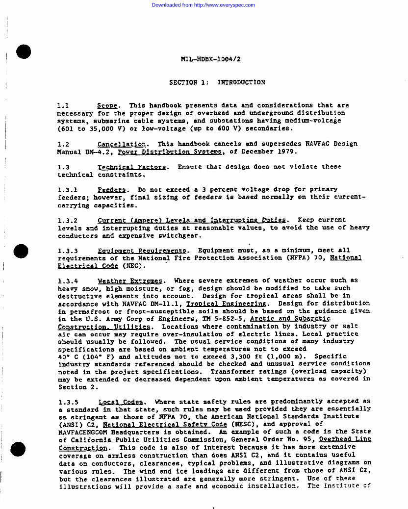
1.1 &w?.!&* This handbook presents data and considerations &hat arenecessary for the proper design of overhead and underground distributionsystems, submarine cable systems, and aubstaticms hawing medium-voltage(601 to 35,000 V) or low-voltage (WP to 600 V) secondaries.
1.2 !2n~ell tia on. This handbook cancels and supersedes l!WFAC DesignManual DM-4~2, ?ower Ilist-ribution hmt!2E&
,,$ of December 2979.
1.3.1 r~s. Do not exceed e 3 percent voltage drop for primaryfeeders; howemerD final sizing of feederff&e baaed normally on their currerlt-carryin,gcapacities.
1.3.2 ent el Le ela and Int~ Dutiesv * Keep currentlevels and interrupting duties at reasonable values, to avoid the use of heavyconductors and expensive switchgear.
1.3.3 Req,$rementtz ● Equipment must, as a minimum, meet allreqmiremeritsof the Nationql Fire Protection Association (NFPA) 70, Mat$enaElec rical Codet (mEC).
1.3.4 weather E‘xtreme~. Where severe wctremes of weather occur such asheavy snow, high moisture, or fogt design should be modified to take suchdestructive elements into account. Design for tropical areas shall be inaccordance with I’WVFACDl$-11.1, Design for distributionin permafrost or frost-susceptible soils should be bused on the gufdance givenin the 0.S. Army Corp of Engineers, TM 5-852-5, ikrctictgxllaxcti%@.Wtr’!Jc~ l?a~ Locations where contamlrtationby industry or saltair can occur may requi~e over-insulation of electric lines. Local practiceshould usually be foJ.lowed. The tasualservice contl$tiomsof many industryspecifications are based on ambient temperatures mot to exceed40” C (104” F] and altitudes not to exceed 3,,300ft (1,000 m). Specificindustry standards referenced should be checked and unusual service conditionsnoted in the project specifications, Transformer ratimge (overload capacity)may be extended or decreased dependent upon ambient temperatures as covered inSection 2.
X.3.5 Local Cod.#J. Where state safety rulca are predoudnantly accepted asa standard in that state, such rules may be maed provided they are essentiallyas stringent m those of NTPA 70, the American 13ationalStandards Institute(ANSI) C2, Eat*o@ ‘ElectricalSefetv Cadq (HESC], and approval ofNAYFACEXTGCOMHeadquarters is obtained. Am example of such a coUe is the Stateof California Public Utilities COmmiSSiOXJPGeneral Order No. 95, a ead LinqComstruction. This code is also of interest because it has more extensivecoverage on armless construction than does ANSI C2, and it contains usefuldata on conductors, clearances, typical problems, and illustrative diagrams onvarioua rules. The wind and ice loadings are different from those of ANSI C2,but the clearances illustrated are generally more stringent. Use of theseillustrations will provide a safe and econom~c installation. The Institute C:
1
Downloaded from http://www.everyspec.com

MIL-HDBK-1004/2
Electrical and Electronics Engineers (IEEE) also publishes Clapp, W
Handbook which was developed to aid users in understanding and correctly
applying this code.
1,4 Economic Factors. Base the number of circuits and voltage on
economic considerations. Where necessary provide life cycle cost analyses in
accordance with NAVFAC P-442, Economic Analvsis Handbook.
1.4.1 Number of Circuits. Keep the number of circuits to a minimum
without compromising reliability, continuity of service, or any of the
technical factors stated previously and thus avoid excessive initial cost.
1.4.2 ~e . Select a distribution voltage which most economically
provides for the magnitude, voltage regulation, and length of feeders (refer
to NAVFAC DN-4 .1, Pre iminar~pn Considerations) . Where groups
of large motors are to be served by the distribution system, the most
economical motor voltage is generally the most appropriate distribution
voltage.
1.4.3 ~ er Losses. Most manufacturers offer a variety of designs
where decreased loss design is offset by increased cost. Both no-load (core)
and 100 percent load (coil) losses, plus transformer efficiencies at various
levels are normally available from the manufacturer. A simplified approach tO
evaluating the cost of transformer losses is given in IEEE 141, Recommended
Practice for El ectric Power Distribution for Industrial P ntla s. A more
exhaustive evaluation treatment of distribution transformer losses is given in0
the Electrical Utilitv Eruzineeriruz Reference Book, Distribution Svstem$ . A
method for specifying a transformer loss evaluation clause is provided in REA
65-2, Evaluation of Lar e~.
1.5 SBecia I Construction. Refer to MIL-HDBK-1004/4, Electrical
Utilization Svstems, for criteria on the design of electrical work installed
in earthquake areas. Refer to NAVFAC DM-4.05, 400-Hertz Medium-VoltaKe
Conversion Distribution and Low-Voltage Utilizgtfon Svstems, for criteria
applying to 400-Hz, 4,160-V distribution systems. Refer to NAVFAC DM-12 .1,
Electronic Facilities Engineering , for criteria on the design of electronic
facilities. Incoming lines to electronic facilities shall be protected
against lightning generated surges in accordance with MIL-HDBK-419, Grounding.
Bondfne. end Shieldine for Electronics Equipments and Facilities.
1.6 ~ystems. For each facility to be
designed, contact the ultimate user and determine the normal and intermittent
maximum power requirements anticipated; the quality limits for ship service
requirements; end the safety regulations and cold iron needs for ungrounded
power systems in accordance with MIL-HDBK-1025/2, Dockside Utilities.
1.7 ~. tice. For recognized good practice in electrical
distribution design, refer to the following handbooks as appropriate to the
requirement:
a) BeemEn, Industrial Pov&r_SXtems Handbsd; ●b) Fink and Beaty, Standard HandbOOk fOr Electrical Enzimeers.
R$_Efrence Book;
Downloaded from http://www.everyspec.com

MYL-HLIBK-1004/2
e
3
Downloaded from http://www.everyspec.com

VIL-NDBK-10@4/2
SECTION 2: OVEKHIAD DISTRIBUTION SYSTEMS
2.1 Circuit IIesi2n. APPIY proper desigr. cziteria (refer to Tebl. e 1) to
the specific project. Also refer to NAVFAC NFGS-16302 and NFGS-16335 and
MIL-HDBK-1190, Facility PlanninF, and Design Guide.
Table 1
Information Required For Circuit Design
i-
Indtidual building
demsnd loads
Coincident peak
dem.md ... .. . . . . . .
LNumber of circuit$
and vdltsge level,
@her considerations
SPECIFIC INFORMATION RE(3UIRE0
Oetermine proposed demand ioads ulilizing calculation methods similar
tothatused in Table40f NAVFAC DM -4.01 or based on field measurements.
Determine facilitypeak demand utilizing calculation me~odssimilar totiat
used in Table 7 of NAVFAC DM -4.01 or based on field measurements.
Select numbarof circuits sndvottageleve!. Number ofcircutis till depend upor
Iocation andmagnitude of individual loads. Voltage level ofweofdis!ributiun
should beinaccordance w4th data in NAVFAC DM– 401. FTovide sufftcienl
future capacity (25percent *).. .
Bdlance single phase loads onmutd-phase circuits. Design large starting
loads to have a minimal effect on demands.
2.1.1 ADD lication. Overhead distribution shall be used in lieu of
underground distribution wherever feasible and effective. Overhead systems
may be the most effective method of service in areas of hea~ load density or
heavy vehicular and pedestrian traffic. However, overhead lines may nor
provide adequate reliability in areas subject to severe weather conditions.
Locations where use of overhead construction should be avoided are covered in
NAVFAC DM-4. 1.
2.1.2 caDacity. Provision shall be made for spare capacity in each
portion of the circuit,
2.1.3 Wire Size. Wire size shall be selected in accordance with the
current-carrying capacity required and, where applicable, the voltage–drop
limitation.
o
2 .1.4 Lh&ical Feature=. Fhysical design features shall be ~~?l.e~:,~d j:]
accordance with the type of circuit involved and the type of distribution;
r.hat is, primary or s.2c.cn?3ry. Select from the following types:
4
Downloaded from http://www.everyspec.com

I
10I
o
141L-1iDBI(-1.004/2
a) Open wire (bare or weatherproof) on insulators.
b) Aerial enble, self-supported or messenger-supported, consistingof insulated bundled single-conductor cable or multiple-conductor cable.
2.2 . Pole lines shall be designed based on materials andconstruction methods specified in NAVFAC NEKS-16302.
2.2.3 lQMla* Wood, concrete (reinforced with prestressing orpretensfonb.g>, or metal (steel oz alumhzm) my be used. Use concrete ormetal poles only where they are more economical or upecial considerationswarrant their use. Wood poles and crossarms shall be treated as covered inW.AWAC MFGS-16302.
2.2.1.2 d CM6 seq. Limitations on pole heights and classes forwood poles are given in Table 2. Class noxmally used .refersto primary polesspaced not more than 200 ft (61 m) apart, which serve industrial or housingareas and which are generally at least 40 ft (12 m) or more in height. SeeANSI C2 for definition of classes. Refer to Table 3 for data on transformerpoles. Refer to Fink and Beaty, Standard Handbook for Electrical Enfiineers todetermine the limitations an minimum heights and classes for poles carryingother equipment.
table 2Height and Class of Wood ?oles
i
PQI..EUSE~ MINIMWI HEIGHT “ MINIMUM CLASS CIASSNOf?MALLY
FEETIMHERS)I PERM17TED $JSED
!Jnapole.... 30 (9) 5 3or4
cOmBrpOk9@yed) 30 (9) 5 3or4
Comrpole(lmguyed) 30 (9) 2 -.
Daadandpok(gqwl) 30 (9) 5 3or4
Deadend@aWnguyed).......,.,..: 30 (9) 3 --
?mnsfomerjxies..... 35 (10.5) SM Table3 2or3
Transformerplatformusingtwopow:(1]’l%istkgpobs... “’” 5 .,..
m wwpdos....t. .... 3 ....
Llndargroundmbleri5erpoW2.4#vu35kV 3 ..,,..,............. ,.,,
iPob-topwdtch...,.. , ““. 3 ....
—..
Downloaded from http://www.everyspec.com

MIL-HDBK–1004/2
Table 3
Wood Pole Sizes for Single Pole Transformer Installations
htAXJMUM TRANSFORMER RATING (KVA)-71
N
+
POLE ONE ‘-”- BANK OF THREE
\ THRE:::HASEJINIMUM CLASS SINGLE - PHASE SINGLE - PHASE (CLUSTER MOUNTED),
5 ,, ...,, 5 ... . ,,.
4 . . . . . . . 15 . ,,.
4, . . . . . . . 25 .,.
3 . . . . . . . . 37- !12 15
3 . . . . . . . . .,, , 3-15 30
2 . . . . . . . . 50 3-25 45
2 ,,, ..,, 75 3-37-li2 75
1 . . . . . . . . 100 3-50 A!2-~12
2.2.1.3 ~ ements. Refer to Fink and Beaty, Standard Handbook
for Electrical●
En.eineers and ANSI C2 to determine the adequate physical and
structural requirements.
2 .2.1.4 Safety Factors. Refer to ANSI C2 for the minimum safety factors to
be used.
2.2.1.5 pole Installation. For pole depth, refer to the criteria in Fink
and Beaty, Standard Handbook for Electrical Eneineers and ANSI C2. Refer to
Fink and Beaty, Standard Handbook for Electrical Engineers for pole placement
with respect to anchors or braces. Footings or reinforcements of the pole
butt-end shall be as required by foundation conditions.
2.2.1.6 Configu ratiou. Armless construction shall be used for aerial lines
because it is less costly than cross arm construction and its use is
aesthetically preferred. For the same reason, use neutral-supported,
secondary cable over rack-supported individual conductors.
2.2.1.7 Crossanns. Crossarms shall be used mainly for equipment support.
Follow the criteria in Fink and Beaty, Standard Handbook for Electrical
Errs i neer>.
2.2.2 Guvs and Anchors. GUYS and anchors shall be provided to support
poles or line towers against horizontal unbalanced loads caused by angles,
corners, and dead enda of lines and where required because of extreme wind
loadings. Refer to Fink and Beaty, Standard Handbook for Electrical Engineers
for criteria. ●2.2.2.1 Safetv ReauiremenXS. Refer to ANSI C2 for minimum safety
requirements.
6
Downloaded from http://www.everyspec.com

2.2.2.2 )ksim of Earth An- ● Chneult the manufacturers* catalogs fortypes of earth anchors and design data. Select the equipment sui~able for theparticular sail conditions and the construction method co be used. Refer toNAVFAC DM-7.02, and Earth Structur~ for additional data onanchors.
2.2.3 J@J&Xc.EE&. Refer to Fink and Beaty, ~gtard I?andbookforElect~fc En@lneers for conductox characteristicf3.
2.2.3.1 $2zc L$ i atiQXL“mt ‘s. Normally limit the use of pole line conductors inaccordance with Table 4, except for primary wires which usually should be not~f=s than Iio. 6 AWG (13.3mm21 copper or No. 2 AWG (33.6mm2) aluminum. merange of conductors in Table 4 gives the most economical system from theinstallation, operational, and maintenance points of view. Special instancesmay require larger conductors. Xn all cases be sure that the type and size ofconductors used has adequate strength for span lengths and loading conditions.Select conductor sizes to provide required minimum strengths in acc~rdancewith loading requirements of ANSI C2 for areas in the United States and inaccordance with facil$ty loadin~ requirements for areas outside the UnitedStates.
Table 4Conductor Sizes for Overhead Lines
~
I
SEECO!4QUCTCIR ..
TYPE ,
Natlar$Jerthan Notsmtiar Than ~
\ Copper...............I
4/OAWG [407mm2) 8 AWG (8.37mm2)
[~............. 336.4&cm (170rnin2) 6AWG f13.3mm2)
1
2.2.3.2 Pama 1 Pr&?lrv m . Normally, bare conductors shall be specifiedfor primary lines stranded or solid construction as suitable to the size andcomposition as follows:
a) copper conductor, (Cu);b) aluminum-alloy conductor, (MC);c) aluminum conductor, steel reinforced (ACSR); andd) high-strength all-aluminum alloy conductor (A&X>.
2.2.3.3 Xr Pico al and Semitropical ● l?ortropical and semitropicallocations AAAC shall be used rather than ACSR because the steel strands of tlwACSR are susceptible to corrosion.
2.2.3.4 ~Rqcial Primarv Ltne. In special instances, use of other conductorsprimary conductors. Insulated conductor, copper ornonmetallic sheathed or me~allic sheathed, messen&er-is used where necessary to avoid exposure to open wire
7
A
Downloaded from http://www.everyspec.com
MIL-HDBK-1004/2
hazards; for example, high reliability service in heavy storm areas. Compound
conductor materials such as copper-clad steel, aluminum-clad steel, galvanized
steel, or bronze are used to provide high strength or corrosion resistance.
2.2.3.5 Utili zation Lines. For secondary or service drop cable, use
insulated multiplex type, either copper or aluminum.
2.2.3.6 Dissimilar Conductor Connections. Appropriate connectors shall be
installed that are specifically designed for such use where necessary to
connect aluminum conductors to copper conductors, in accordance with the
instructions of the manufacturer. Contact with dissimilar conductor
materiala shall be minimized.
2.2.4 In sulators . To support bare or weatherproof conductors, select from
the following types of insulator, as appropriate to the installation:
6)b)
c)
d)
e)
suspension type, single or multiple;
spool type;
line-post type;
strain type; and
pin type.
2 .2.4.1 Insulator Combinations. Various types of insulators may be
combined; for example, strain type for anchor poles or dead ends with either
pin or line post for line insulation. ” Line-post types are considered to be o
both less expensive and superior to pin types.
2.2.4.2 ~ d Loads. For dimension of insulators and permissible
loads, refer to the ~ as follows:
a)b)
c)
d)
e)
f)
g)
C29.1, Test Metho s or~ ators;
C29 .2, Insulators. Wet-process Porcelain and Touflhened GISSS.
SusDensi On TV De ;
C29.3,
C29.4,
C29.5,
T.YZ2s;
C29.6,
C29.7.
W&‘C29.8.
Wet-Process Porcelain Insulators. Suool TYoe;
Wet-Process Porcelain Insulators. Strain Tvpe;
w~ Ow- a edium-Voltaze
Wet- cess Porcelai~;
Wet-Process Porcelain In sulators. Hi~h-Volta~e Line-Post
v~ aratus Ca and Pin
‘ND e: and
i) C29.9, Wet-Process Por celain In BUlatOrS, ADDaratUS pOSt-~Pe..
In addition to the above, refer to the Hational Electrical Manufacturers
Association NEMA I-IV-2, ADPli CatiOn Guide for CeranIi C SusDensi On Insulators.
Also, refer to Fink and Beaty, standard Handbook for Electrical Engineers.
I 2.2.4.3 Insulation Levels. The application of ANSI C2 requires higher
insulation levels in locations where severe lightning, high atmospheric
cent.axcination, o? other unfavorable conditions exist. Thfs appIieso
particularly to areas where saltspray contamination can cause increased
I operating stresses. Local practice in such areas should be checked in
k 8
Downloaded from http://www.everyspec.com

e
I
I
‘o
I
1
I
I
aI
M3L-1’iDBK-1004/2
determining how much increased insulation is considered necessary forinsulators and whether increased leakage distances far bushings and cableterminations is aho desirable.
2.2.5 Bard‘w&rg,, M locations semitive to electromagnetic interference,Mnes should be installed underground. If aerial lines are provided,insulators must be of the radio-freed type. Hardware components should beprovided with lockmuts to avoid Iooee connections, which could cause static.Locknuts must be threaded, and of a type which will prevent loosening of theconnection when wood members shrink.
2.3 ~ulation. ‘Thevoltage drop for primary lines shall notexceed 3 percent. The power factor of the line should be maintained at+ closeto un%ty ae economically practical so as to minimize system XosneB.Regulation utilizing load-tap-changing cransformer~ to correct line voltagevariations resultimg from changing loads or utility company aendimg-endvoltage swiuE ia covered in Section 5. Reqtiirementsfor line equipment areas follows:
2.3.1 Stem-Voltafz lle~ Ulatom. Step-voltage regulators can rarely bejustified irconomicall~for new construction. They may be used cm existimgconstruction to meet voltage drop criteria when proven to be more costeffective than controlling the vo~ta~e drop by use of larger conductors,provision of addition-l lines, or by the installation of capacitors. Refer toFink and Beaty, dard Handbo ko for Ele?t~ for methods ofsizing feeder voltage regulator and for regulator 8afety and If.nedropcompensation setting requirements. Single-phase regulators are preferable as‘beingless costly but [email protected] more installation apace.
..
2.3.2 Gapacitore. Capacitors raise voltage levels by reduc%ng thereactive line losses associated with reactive current flow between thecapac$tor installation and the power supply. It is rarely economical to applythem for voltage improvement only. Capacitors are justified when their costover their aerv%ce life ie less than any utility company low-power-factorpenalty cost. The cost of switchtng equipment to meet any functional orutil!ty company prohibitions against a leading Rower factor must also be takeninto account. Base design on shunt power capacikora that conform to IEEE 18,s~= t Power Can citor~a . Take into account the followhg cons~derations:
a) Fixed capacitance is the amount of capacitance that can beapplied continuously without excessive voltage rise at reduced load.
b) Switched capacitance is an additional amount of capacitance thatcan be applied, if provision is made to witch off this additional amount whendemand is reduced.
c) Select the type of capacitor switching that i~ best for tiecondition at hand. Possible choices include remote control of the capacitorswitching device, time clock control, or power factor or voltage sensitiverelay control.
d) Install capacitors in banks ontion, as near as possible to the centroid ofrequire~.
9
poles, at-grade, or in a substa-the area where correction is
I
Downloaded from http://www.everyspec.com
MIL-HDDK-1004/2
2.4 ~ransformers . Transformers can be mounted on poles, at-grade, or
indoors depending upon size and site requirements. Select a standardized
three-phase transformer, except where the load is small enough to justify a
single-phase transformer. Use oil-insulated transformers, except where site
conditions or economic considerations make their use prohibitive. Consider
loading, noise level, and transformer protection reguircments.
Askarel-insulated sad non flatsrsable, fluid-insulated transformers shall not be
used because of environmental concerns as to their insulation liquid. Use of
other types of insulation must be economically or functionally justified.
Less- flssrsable, liquid-insulated units may be necessan where oil-insulated
transformers cannot meet fire-exposure requirements as listed in MIL-flDBK-
1008, ~ Desie.n. and Construction.
Epoxy-encased ventilated dry-type units may be appropriate in areas where
liquid-insulation loss might result in water pollution.
2.4.1 Pole Mounting. For single-pole mounting, llmit the size of single-
phase or three-phase units in accordance with Table 3. Pole-platform mounting
(two-pole structures) shall not he used , except in instances where other
methods are not satisfactory. It iS recommended that maximum transformer size
be limited to the sizes shown In Table 3. For installations of 225 to 500 kVA;
pad-mounted, compartmental-type transformers are recommended.
2.4.2 At-Grade fiountin&. For at-grade mounting on a concrete base, there
is no kVA limit. Tamper-resistant transformers (classified as pad-mounted
compartmental-type units) should generally not be specified in ratings of over ●500 kVA, but in no case larger than 750 kVA. When sheet-metal enclosures are
not tamper-resistant, ground-mounted units shall be provided with a fenced
enclosure or even a concrete or brick structure, where adverse weather
conditions make such an installation advisable. For required clearances
between buildings and insulated transformers, refer to MIL-HDBK-1OO8.
2.4.3 I ndoor Installations. Indoor installations are covered in Section 5
2.4.4 Overload Cauacity. Consider the accelerated loss of equipment life
if transformers are to be overloaded. Refer to ANSI C57.91 Guide for Loading
Mineral-Oil-Overhead and Pad-Mount ed Distribution Transformers Rated 500 kVA
and Less with 65 Degrees C or 55 Deerees C Averaze Winding, C57.92 Guide for
Loadinz Mineral-Oil-Immersed Power Transformers UD to and IncludinR 100 MVA
with 55 Degrees C or 65 nsDegrees C Windi Rise, and C57 .96 Guide for LoadlnR
Pm-~P e Distribution and Power Tr ansfonners and Fink and Beaty, Standard
Bandbook for Electrical E uineers.
2 .4.5 ansformer Noise Level. Refer to NRNA TR-1, Transformers.
Eee ulstors an d Reactors for maximum permissible noise levels for transformer=.
2.4.6 Ov rhead~n. The criteria in ANSI C57.12,20, ~eauirements
for Overhead -e Distribution Transformers. 50 0 kVA and Smaller: Hti h-Volt axe
67.000 Volts and Below: Low-Voltage 15.000 Volts and Below shall be used. Do
not use self-protected transformers having an internal secondary breaker,
internal primav fusing, and integrally mounted surge arresters. These
transformer accessories are provided for transformers generally described by ●industry as a pole-mounted type. The replacement of fuse links is considered
to require specialized personnel not usually available at naval facilities.
Downloaded from http://www.everyspec.com

2.5 circuit ln~runti Vg Devices. Select from fuses, circuit breakers,and automatic circuit reclosers for protective line considerations. Switchesshall be used to localize defective portions of aerial and umder~roundcircuits and to acconglish dead-circuft work. Select from nonload-break orload-break type sw5tches.
~ 2.5.1 Fuses. After consideration of the necessary current-carryingcapacities, interraptln,gduties, and time-current melting and clearing
1’characteristics, select fuses from the followtmg types:
Ia) open fusible Iink$
,
1.
b) expulsion type,c) boric-acid type, andd) czxrrent-llmitingtype.
2.5.2 IWrent b~ pr tea Ctar$+. These fusible type devices developedunder an Electric Power Research Institute (EPRl) project, provide current
limiting on up to 15.5-H systems for VP to 1,200 A continuous currents. Theyshould only be used where higher continuous ratin~a are required than areavailable from standard fused cutouts or power fuse disconnecting units.1
2.5.3 ~. Utilize a circuit breaker rating adequate for the
a
load interrupting duty antiwhich provides selectivity with circuit breakersand fuses ahead of or after the circuit breaker.
2.5.4 W?xUM.!~c ~~rc~~t $ecl06ers. The criteria in NEPIASG-13, AutomaticCircuit Reclosers. Ut.o~4.tic Line Secticmalizers and Oil-~ed CapacitorSwitches for Al~atl nn urrgD&_Sy_ shell be used. Use of automaticreclosing for other than overhead lines serving residential or commercialloads may cause problems. In selecting the type of automatic circuitreclaser, consider the reliability and continuity of service. Reclosers mayconsist of a circuiz breaker or a multiple switching device. Reclosersoperate so that a faulted circuit may be opened and then, eitherinstantaneously or with deliberate time delay, reclosed. Up to threereclosures with varying time intervals may he used. Coordinate automaticcircuit reclosers with fuses or circuit breakers on the same circuit.
2.5.!3 lTonload-BrealcSw$tW. Use nordoad-break switches only for theinterruption of circuits that carry no appreciable load. Select the type
I applicable, depending on circuit importance, load, voltage, and fault circuitduty. The types available are porcelain disconnect fuse cutouts, plain orfused single-pole air disconnect stitches, and disconnect fuse cucoucs of
I various types. Refer to manufacturers’ catalogs and NEMA SG2~ Hi~h-VoltaU~~s: Disconnecting and horn sap switches covered by ANSI C37.30, Definitionsm aui,,rements fox. h-Vo ta AW 1 ~e ir Switches. ImqJLQ&Qzs. and Bus SUPQ arts
and ANSI C37.32, Schedules of Preferred Ratimts. Manufact- SneCifications,and ilnvlication Guide for Himh-volt~ Switches. BUS SUDDOrtSs and Swi.teh
/ ~orieq are also nonload-break switches.
,0 2.5.6 ~oad-Break Swit-. Load-bxeak switches are provided with aninterrupting device capable a?!disconnecting circuits under load. Fusecutouts, (covered by NEMA SG-2) which are cies:ignedto bc load-break are
I
Downloaded from http://www.everyspec.com

MIL-HDBK-1004/2
available, as are load interrupter switches which conform to ANSI C37 .30 and
C37.32. Vacuum switches provide load-break features. Vacuum switches can
provide a wide variety of operators and should be considered as an economical
method of providing automatic or remotely controlled switching,
2.6 Lizhtninc Protection
2.6.1 Requirements. Lightning protection can be provided by installing
surge (lightning) arresters, open or expulsion gaps, or overhead ground wires,
or by all three methods combined. The weather shall also be considered. For
most distribution circuits, distribution surge arresters protecting
transformers and aerial-to-underground transitions are adequate. Overhead
ground wires are rarely considered to be an economical installation for
distribution lines, but are often used for protection of transmission lines.
In areas where annual lightning storms are few, no protection for
lightning-induced surges may be necessary. Local naval faci.llty or utility
company practice should .%enerally be followed (refer to NAVFAC DM-4.6,
LiRhtninz (and Cathodic) Protection) for equipment protection,
aerial-to-underground transition points, and other appropriate locations.
2.6.2 ~n. Select the proper arrester in accordance with the
Basic Impulse Insulation Level (BIL) that applies to the voltage level of the
circuit. Follow the criteria in ANSI C62 .1, Surze Arrestors for AC Power
Circuits; ANSI C62.2, Guide for~ Surge AEresters for
Alternating Current Systems; and ANSI C62.33, Va~e ●Devices.
2.-f Clearances. The necessary horizontal and vertical clearances shall
be provided from adjacent physical objects, such ss buildings, structures, or
other electric lines, as required by ANSI C2.
2.7.1 ~.Contin anc Provision shall be made to protect
against contingency interferences, such as broken poles, broken cross arms, or
broken circuit conductors.
2.7.2 M~ns. Provide for clearance conditions arising
from multipurpose joint use of poles.
2.8 Grounding. For information on grounding of overheacl distribution
systsms, refer to ANSI C2.
2.8.1 Safety. Provide grounding for all equipment and structures
associated with electrical systems to prevent shock from static or rfynsmic
voltsges.
2.8.2 ~h . Provide a low impedance path at the source
of fsult currents, if a circuit contains a deliberate ground connection.
2.8.3 Maximum Ground Resistance. Msximum ground resistance shall not
exceed values specified in NAVFAC NPGS-16301 and NPGS-16302, and ANSI C2.
Consider the source of electric power, capacity, magnitude of fault current,
and method of system grounding, as they affect this resistance.●
12
Downloaded from http://www.everyspec.com

e !mL-HD$lt-loo4/2
2.8.4 Gro ms!~~~Methods. Grmmcling provisions shall conform to NFPA 70.Grcmnding met~odk+for transformers mounted at grade are covered in Section 5.
2.8.4.1 GrOum! Rods. Ground rods may be used either singly or in clusters.Dr2ve the ground rods to ground water level for an effective and permanentinstallation. Provide for corrosion prevemtlon by a proper choice of metalsor by cathodic protection. Where Browmd water cannoc be reached, chemicalssuch as magnesium .sulphate (MgS04) or copper fmlpba$e <CUs04) IIMYhe usedto improve soil conductfwiry where n,ecessa~. Manufacturers of ground rodscan provide data on such treatment. Provide for easy maintenance and periodictesting. Driving ground rods deeper using Bectional rods may be moreeffective than using multiple rods. Zn many cases, soil variations andpossible bedrock may make provision of additional rods less expensive.
2.8.4.2 Water Pine Connect-. No connection shall be made to anYsprinkler piping in accordance with NFPA 24, n~o~ of Private FireService ?lainsand thei~ a-. The electrica3 system may be groundedto a water supply system except where nonmetallic pipes, catholicallyprotected metallic pipes, or insulating couplings are incorporated in thewater pipe system. The water pipe correction shall be supplemented by othergrounding electrodes where required by HFPA 70.
0 2.8.4.3 $&g&@ption of Grounti~ . Where the ground resistance in anexisting system is high, any of the aforementioned methods may be combined toeffect improvement. .
2.8.4.4 Ground ConnectiotaQ. Wires running from protective devices <for.-example, gaps, grading rings, expulsion or protection tubes, and surgearresters) to ground shall be kept as straight and short as possible. Where
I bends are necessary they shall be of large radii to keep the surge impedanceas 10%?as possible.
2.8.5 @et&ad Ground Elir~. Where overhead ground wires are used forprotection of electric limes, a ground connection shall be provided from theoverhead ground wire to a wire loop or a ground plata at the base of the pole
4 or to a driven rod, depending on the existing soil conditions. Use of wirewraps or pole butt plates is allowed by ANSI C2 only in areas of very 10V soil
resistivity. The overhead ground wire mast be grounded at each pole.
I 2.8.6 ~easurement of Gro~ . Ground resistance shall bemeasured by using one of the following methods:
[ a] de Methad. M the three-electrode method, two testI electrodes shall be used to measure resistance of the third electrode, the
ground point. A self-containectsource of alternathg current and abattery-operated vibrator source providing direct reading art?commerciallyavailable.
‘0 b) FalX-of-Pot~al Method, The fall-of-potential method involvesan ungrounded alternating current power source which circulates a measuredcurrent to ground. Volta~e readings taken of the connection to aux%ltarygrotm!s allow use of Ohm’s law to determine the ground resistance. Refer toFink and Beaty, Standard liandbq-~k.foT_EJectr~c@ lht~l~.
Downloaded from http://www.everyspec.com

MI L-HOBK-1004/2
2.9 Service DroD tO Build&n@,S. Local considerations and current
capacities shall dictate the type of service drop to buildings from overhead
distribution systems. Provide either underground service into the building
from a pole riser or self-supporting service cable strung from the pole to the
building (refer to ANSI C2).
2.10 J?iEht-of-Wav. When not installed on government property, a right-
of-vay for the electrical distribution or transmission system should be
obtained by outright purchase of the land or by limited or perpetual
easement . In the case of easements, the right to perform maintenance on the
line must be covered.
2.10.1 Widths . Where possible, the width of the right-of-way shall be
sufficient co avoid all conflicts (refer to ANSI C2) between the line and
other adjacent structures. This width shall include all obstructions and
underground utilities, except where necessary for the underground utilities to
pass at right angles to the right–of-way. The requirements for minimum width
on naval activities shall conform to the following right-of-way widths:
Line voltaEe (kV) Recommended minimum riaht–of-wav width
across unim roved~> meters
upto 7.5 . . . . . . . . . . . . . . . . . . . . 40 (12)
7.5t020 . . . . . . . . . . . . . . . . . . . . 60 (18)
2oto 35 . . . . . . . . . . . . . . . . . . . . 80 (24)
35t068 . . . . . . . . . . . . . . . . . . . . 80 (24)
68t092 . . . . . . . . . . . . . . . . . . . . 80 (24)
92t0120. . . . . . . . . . . . . . . . . . . , 100 (30)
2.10.2 ~. Because trees adjacent to any overhead line pose a line
clearance problem, ensure that growing trees do not result in sny line outage
or damage. Complete removal of s1l trees in the right-of-way is probably
environmentally unacceptable. Tree species, which in conjunction with the
weather and soil condition are liable to uprooting shall be removed if their
location poses a clear danger to the line. Otherwise trees shall be trimmed
to provide a hazard-free operation for at least 2 yeare. Competent persons
shall do the trimming to avoid excessive tree dsmage and to assure that trees
off the right-of-way are not trimmed by mistake. The lsndowner’s permission
shall be obtained for any trimming and a though clesnup after trimming shall
always be conducted.
14
Downloaded from http://www.everyspec.com

MIL-lUIBK-1004/2
Section 3: UNDERGROUND i)ISTBIBUTIONSYSTEMS
3.2 CJxcwft IMsilm . Follow the circuit design procedure outlined inSection 2 of this handbook for overhead distribution systems. Per additionalcriteria$ refer to MIL-HD?K-1190.
3.2 Pirect Burial. Direct-burial cables only shall be installed in
areas that are rarely disturbed. After first considering economic,maintenance, and reliability effects, restrict direct burial to light Ioadsjco roadway Iig,httng systems. and to long wntapped runs in 10V density areas.In some instances, a.minimal amount of taps may be acceptable.
3.2.1 l’rate~tion. Far protection against mechanical injury, medium-voltage &irecc-burial cables can be provided with a protective covering ofmetal armor. Weed for such protection, such as against dig-ins or because o{possible termite or rodent attack, should be considered on a case-by-casebasis. Possibly other protective means are more economical. Where corrosionconsiderations are of importance, armored cables shall be provided with aphstic or symthetic rubber jacket. For cable ispecifications,refer to NAVEXNFGS-16301. Provide a colored warning tape 6 im. (52.4 mm) above thedirect-burial cable.
3.2.2
3.2.2.1 ~rench Di ensiou . Trenches shall be provided in accordance withthe requ$rcments ofm?lAVPACNl?GS-16301and NFGS-02225.
3.2.2.2 Gable ~r~te~ti011. General installations shall be in accordance withrequirements of NAVFAG MFGS-16301. Where additional protection of buriedcable against dig-ins Is necessary, provide a continuous l-in. thick treatedwood plank or a concrete slab, not less than 2 im. (S0.8 mm) thick~ locatedd%rectly above a top layer of sand in lieu of or in addition to a protectiveccwerin$. Protection against termites or rodents shall be accommodated byusing a clwm%cal treatment. The treatment shall be approved by the facilityprior to use.
3.3 Praw-h svst~,. Draw-in systems consist of duct systems (which mayinclude access points such as manholes and handholes) In which cable is drawnafter the duct system has been installed. Provide a draw-in system whereoverhead distribution is not feasible (refer to I?AVPACDM-4.1). Provide adraw-in system for distribution of large blocks of electric power, where manycircuits follow the same route or are run under permanent hard pavements, orwhere service reliability
3.3.1 DUCt Lines
3.3.1.1 l@w20 selectm$,nimumcost and to avoidstructures.
is paramount.
duct line routes to balance maximum flexibility withfoundations for future buildings and other
3.3.1.2 Multinuroose Conditiw. Where it may be necessary to runcommunication lines along with electric power distribution lines, provide two
Downloaded from http://www.everyspec.com
MIL-HD9n-loo4/2
isolated systems in separate manhole compartments, Where possible, run ducts
in the same concrete envelope.
3.3.1.3 Clearance. Electric and communication ducts shall be kept clear of
all other underground utilities, especially high-temperature water or steam,
pipes.
3.3.1.4 Materials. Acceptable standard materials include the various types
of plastic as specified in NAVFAC N?’GS-16301. Rigid steel conduit may also be
installed below grade and shall be provided with field or factory applied
coatings for corrosion protection where required.
3.3.1.5 Size of Ducts. The size of conduits in a duct bank shall be based
on consideration of the following factors:
a) for general electric pover distribution, do not use less than 5
in. (127 mm) ducts;
b) for communication duct banks, normally use 4 in. (101.6 nun)
ducts although 3 in. (76.2 mm) ducts may be acceptable in some cases;
c) special cases may require use of larger sizes, but such sizes
shall be functionally justified.
3.3.1.6 Arrane ement of Duct Banks. For best heat dissipation, use an ●arrangement of two conduits wide or high. This may be impossible where a
large number of ducts are involved. The vertical, two-concluit-wide
arrangement enables the cables to be more easily racked on manhole walls but
may not be as economical as the horizontal two-conduit-high arrangement. For
dimensions and arrangement of duct banks see Figure 1. Conduits shall be
encased in concrete in accordance with NAVFAC NFGS-16301.
3.3.1.7 Drainage. All ducts to manholes shall be drained with a constant
slope in accordance with NAVFAC NFGS-16301. Where two manholes are St
different elevations, a single slope following the general slope of the
terrain may be the most economical. Where grades are flat or crest between
manholes , a single slope usually requires too much depth In one of the
manholes . In this event, generally slope the duct from the crest area to both
manholes, keeping a minimum earth coverage on the highest elevation.
3.3.1.8 ?,vare Capacity. Sufficient ducts shall be included for planned
future expansion. A additional minimum of 25 percent spare ducts for all new
underground systems.
3.3.2 Manholes and Handholes. Double manholes shall be used where
electric power and communication lines follow the ssme route. Manholes and
handholes shall be of a suitable type selected from NAVFAC NFGS-16301.
3.3.2.1 Selection. Factors bearing on the choice of manholes and handholes
are number, direction, and location of duct runs; cable racking arrangement;
method of drainage; adequacy of work space (especially if equipment is to be
installed in the manhole); and the size of the opening required to install and
●remove equipment.
16
Downloaded from http://www.everyspec.com

oMIL-HllBK-1004/2
3.3.2.2 &ocatioq. Manholes or handholes shall be placed at streetintersections, where required for connection or splices, and where necessaryto avoid conflict with other utilittes. Hanhole separation shall not exceed600 fz (182.8 m) on straight pulls and 300 ft (91.2 m) on curved duct runs.Decrease spacing where necessary to prevent installation damage. Limit pull-im strain to a point that will mot damage cable hsulacion or deform thecable. A description of maximum permissible pulling forces is given in thev~demrmmid Svst_efer e~qe Beak.
3.3.2.3 X* “Manholes shall be used for all main duct runs and wherevermedium-voltage cable is imstalled. Handholes may be used on laterals frommanhole and duct line systems for low-voltage power and communication linesfor buildin~ services.
3.3.2.4 Ccx’lstr’Uction of Manh It?s. Manholes shall not be less than 6 ft(1.8 m) in depth, by 6 f% in I“agth, by 4 ft in width with an access openingto the surface above (opter air) of not less than 30 in. (762 mm) indiamezer. Mudmles shall provide a minimum wall space of 6 ft on all sideswhere splices are to be racked. Duct entrances into che manhole can belocated near one end of long walls so that sharp bends of cables at the ductmouth are avoided, or else sufficient space shall be pro~ided for a reversebend before the cable straightens out on the wall on which the cable is to beracked.
a3.3.2.s $~nstr=~i=of Handh@les. Handholea should be mot less than 4 ftin depth, by 4 ft (1.2 m) in length, by 4 ft in width with a standard manholecover and mmp of the same type provided for manholes. Generally at leastfour racks should be installed. Where more than two splices occur, a manholemay be more appropriate. Where splicing or pulli~ of low-voltage orcommunication cables requires an access point, but the volume provided byhandhole is unnecessary, pullboxes may be more suitable for the installation.
3.3.2.6 w. A set of spare stubs shall be provided so that the manholewall will not need to be disturbed when a future extension is made.
3.3.2.7 Hard arq Select hardware applicable to each installation (refer toIWVFAC NFGS-li;Ol): Where end-bells are provided, cable duct shields arenecessary only for protection of metallic-sheathed cables.
3.4 mdersmound C-. Cable installations make up a large portion ofthe initial distribution system investment, contribute to a lesser extent tothe annual maintenance and operating costs, aridaffect system reliability.
Therefore, underground cables an~ their aecompaaay%ngprotective and operatingdevices should be selected in accordance with criteria set forth in thefollowing paragraphs. The joint specifications of the Insulated CableEngineers Association-National Electrical Manufacturers Association(ICEA-NEI’4A)and the specifications of the Assoc5atim of Edison IlluminatingCompanies (AEIC) should be used as cowered by 13AVTACNFGS-16301. ICEA-NEMAspecifications cover medium-voltage cables which are manufactured as stockitems. Requiring medium-voltage cable to meet A.HC specifications should be
elimited to medium-voltage cables wh~ch are not stock items (35-kV rating) orwhere the footage installed is large Enough for manufacturers to make aspecial run.
Downloaded from http://www.everyspec.com

MIL-HDBK-loo4/2
.
(7.:=9
y2“
,,. ~.
(L.)
J-
(7. L)
EM - ‘.
(7.5- (s-) (?.5.+ (5-) 7.3W)
3-
7.5cm . . . .
‘. 0:!0 :p- jJ&j$
.-
:: - 3;0-’ ~~ : @@-@4&:7.s” . ..*... (7.:=. ,. ..., . . ... . . ..
?5.KTSIC OR C(P@tVNICAT1O)i 03MBIND ELECTR1Cm CCWTJNICATIOX
%1.?SIBEINPJRCDENT 1S PWVIDEO lJND~ SAILIIDNI IPACIS :1 SIW1.L
B=OND TUE lN’lES SAILS.
— Ax LUST 12’ (3. S=)
KEINFORCED DUtT -
Figure 1
Duct Line Sections
18
Downloaded from http://www.everyspec.com

o
II
I!
I
1
0I
I
MIL-13DBX-1004/2
3.4.1 e- or Plultinle-Conductor Cable~
3.4.1.1 ~e-COl’MhlCtOr Cableq* Sin&le-conductor cables are usually usedfn distribution systems because the installed cost is less than that ofmultiple-conductor cables.
3.4.1.2 DIC-cfXMhCtOZ Cables. Select multiple-conductor cables wherejustified by special considerationstwisted to provide lower tmluctanceEigh-altatude Electromagnetic Pulse
3.4.2 @nductor Matti
such aa installation in cable trays,for 400-Mz distribution systems, or for(HEMP) hardened systems.
3.4.2.1 ~ealed CQR! . Select annealed copper for high conductivity,flexibility, and ease of handling; It is used in all forms of insulatedconductors*
3.4.2.2 ~edium-Harcl-Drawn~OtlD~ . Medium-hard-drawn copper has greatertensile strength than annealed copper but may not be available as a stockitem. Its use in long pulls and unsupported vertical risers is acceptable;however, procurement difficulties make other designs more advisable.
3.4.2.3 &luminqQ. Generally, aluminum conductors shall be permitted as acontractors opciom to copper subject to the restrictions of NAVP’ACNP6S16301, except where corrosive conditions limit usa8e.
3.4.3 Preferred C@b~@ ImQatims . Insulation material to be used in aspecific design will depend on the system voltage and the thermal, mechamical$and chemical effects from &he installation involved. Crosslinked-Polyetlzylene(XLP) or ethylene-propylene rubber (EPR) shall be used whenever possible.These insulations provide the maximum rated conductor temperatures foroperating, overload, and short-circuit conditions for cables rated up co amaximum of 35 kV.
3.4.3.1 ~ . Both XLP and EPR me themosettixig, solid dielectriccompounds with excellent electrical insulation properties~ good chemicalresistance and physical @tren&th charateristic.s,and both remain flexible atlow temperatures.
3.4.3.2 PfsadvantaR~. Although EPR is more expensive than XLP and bothhave excellent moisture resistance, the degradation phenomenon called treeingappears to occur more frequently in XLP and is aggravated by the presence ofwater. EPR a~so is less susceptible to corona discharge activity than XL?,but in a properly designed and manufactured cable, damaging corona is notexpected to be present at the usual operati~ voltages.
3*4*4 Other Insularimzs. Other insulations shall be used only wherespecial circwmscances warrant their lower-rated conductor temperatures ortheir lover rated maximum voltage class. Use of such cables, especially thosewith metallic sheaths, mmst be functionally or economically justified.
3.4.4.1 ~olvv&Jyl -chlo.r~. Select pol~inyl-chloride (PVC) mainly forpower amd control wiring for ratings of 2 kV or less. This thermoplastic is
Downloaded from http://www.everyspec.com

MI L-HDBK-loo4/z
highly resistant to moisture, oils, chemicals,
dielectric losses.
3.4.4.2 Polvethvlene . Polyethylene shall be
●and abrasion, but has high
mainly selected for roadway
lighting, control, and comm&ica~ion cables. This thermoplastic has good
❑ oisture resistance and stable physical and electric characteristics under
temperature variations. Polyethylene exhibits the same susceotibilitv to
treeing and corona discharge as XLP.
.–— ——. .
3.4.4.3
strength
up to 35
3.4.4.4
to heat,
$Wvl R— ubber. This thermos etting insulation has high dielectric
and is highly resistant to moisture, heat, and ozone. It can be used
kV, but has lower rated conductor temperatures than either XLP or EPR.
Silicone-Rubber. This thermosetting insulation is highly resistant
ozone, and corona. It can be used in wet or dry locations. exDOsed.
or in conduit. It has the highest rated conductor temperatures but ‘can- only’
be used for applications up to 5 kV.
3.4.4.5 Mineral-Insulated Cable. Mineral-insulated cable is completely
sealed against the entrance of liquids and vapors along the cable run. It is
rated at 600 msximurn.
3.4.4.6 BUbbeZ. Rubber insulated conductors shall be used for ease of
splicing, good moisture resistance, and low dielectric losses.
3.4.4.7 Varn ished-Cambric . Varnished cambric insulation shall be used for ●resistance to ozone and oil and for ease of splicing. Use varnished-cambric
principally in conjunction with paper insulation where oil migration is a
problcm. Where installed in wet or highly humid locations or underground,
varnished-cambric must be provided with a suitable sheath. . .
3.4.4.8 PaDer-Insulat ion. Paper-insulation shall be used for low
ionization, long life, high dielectric strength, low dielectric losses, and
good stable characteristics under temperature variations. AS with
varnished-cambric insulation, paper-insulation requires a suitable protective
metallic-sheath. It may be specified as a contractors option when existing
cables are paper– insulated, or as a requirement when the extra cost is
justified because neither fiP nor EPR p;ovide the
3.4.5 Cable Sheaths
3.4.5.1 f?onmetallic. Nonmetallic sheaths shall
repellent, end long-lasting.
3.4.5.2 Metallic. Cables exposed to mechanical
pressure require a metallic sheath, such as lead,
insulations require such protection in all cases,
csmbric.
required qualities.
be flexible, moisture
damage or high internal
aluminum, or steel. Certain
such as paper and vamished-
3.4.6 Cable Cover ines. For corrosion protection of metallic sheaths,
specify a suitable covering or jacket.
●3.4.7 ~i.~1..< d...a>~eses .
is required to confine the
Shielding of a medium-voltage distribution cabie —
electric field to the insulation itself, and to
20
Downloaded from http://www.everyspec.com

MIL-HDBK-loo4/2
prevent leakage currents from reaching the outside surface of the cable.Insulation shielding is required on all nonmetallic-sheathed cable rated 2 kVand above and all metallic-sheathed cable rated 5 W and above. Shieldsshould be grounded to reduce the hazard of shock. Grounding is required ateach splice and at each termination, otherwise d~erous induced shieldvoltages may occur.
3.4.8 Cable SDlicQ . Cable splices shall be provided in accordance with
NAVFAC HFGS-16301. Alum%num-to-copper and nonmetallic-$acketed to lead-covered cable connections are easily made when connectors aridsplicingmaterials are correctly utilized and installed so 8s to prevent smy galvanicaction or oil migration which might occur. While such transitions shall notbe permitted vbem installing new lines, aplicea of this type may be necesaamfor connections between existirujand new work.
3.4.9 gable Fir*oofti . Cables operatfng at 2,200 V or over, or exposedto the failure of other cab2e8 operating at these voltages, must befireproofed In manholes, hard.holes,and transformer vaults, as required byNAVFAC I?FGS-16301. Exceptions may be made where physical aepaxation,isolation by barriers, or other considerations permit, if approved ‘bythelocal Naval Facilities Engineering Commmd (t?AVTACEIUXO?!)having jurisdiction.
3.4.10 ~catio~. Cables shall be ta~ged in all manholes so asto identify eircuity, cable size, cable conductor and insulation type. volkage
rathg, manufacturer, and date installed. Cable identification provided onthe insulation by the manufacturer need not be repeated unless covered up byfireproofing. In hamdholes and at other termination points only a circuit ~identification is required.
3.4.11 Gas Press rized C@b& . Sulfur hexaflouride (SF6) gas pressurizedcable or integrated”gas spacer cable can be considered for use when used witheither XLP or-EPR in~ulations. The jackets of direct-burial cables or field-installed or factory-coilable conduits can be pressurized with SF6 gas,
3.4.11.1 X6 G=. SF6 B&s has f3ve times the density of alr and acts asan “invisible liquid” as *t stays in place even when exposed to air. It iselectro-negative with n.aoxygen or carbon; has a high arc resistance; will notsupport combustion; and is cwlorlessttaateless$ and nontoxic. When used withXLP and EPR insulations, it prevents water vapor diffusion, water treeing, endgaseous ionization. It provides mon%tori~ for %ndication of mechanicaldamage during shipment, installation, and dur%ng operation. S~6 gasimproves the lightning and impulse strength and can provide a rehealins ofinsulation after an electromagnetic pulse insulation failure. The gaspressure prO’tects~&a%nSt inte~a~ cOrrOslOn Of metal R6rts. me SF6 &a8
provides extra electrical strength in splices and terminations.
3.4.11.2 Ins tallat~ . The requirements for integrated gas spacer cable ofN3WA 70 should be expanded to cover the XLP or EPR insulation requirement.Appropriate installation requirements forisubmarinecable should be determined fromindicate temperature ranges, so a gaseousis achieved.
Idirect burial, in conduit, or as
1
manufacturers. In cold climates,mixture which prevents liquification
Downloaded from http://www.everyspec.com

MIL-HDBK-1004/2
3.4.11.3 ODtional Us=. Where adequate requircmentn are provided, gas
pressurized cable ❑ ay be used as an option to cables covered in NFGS-16301.
3.5 Underground Transfomoers. Vaults shall be used to house
transformers and associated equipment for underground distribution systems.
3.5.1 Ea uiDment. Use subway (submersible) type equipment.
3.5.2 Vault Design. The design of transformer vaults shall be in
accordance with MI L-HDBK-1OO8 and shall include the following provisions:
a) Provide adequate ventilation to prevent a transformer
temperature in excess of the values prescribed in ANSI C57 .12.00, General
Requirements for Liouid-Immersed Distxll&L&n. Pcnter and Regulatiw
Tran fomns era, and C57 .12.01, General Requirements for Drv-Tw De Distribution
and Power Transformers. This limitation requires that most of the electrical
heat losses must be removed by ventilation; only a minor part can be
dissipated by the vault walls. ffFPA 70 recommends 3 in.2 (19 cm2) of
clear grating area per kilovolt-ampere of transformer capacity. In localities
with above average temperatures, such as tropicsl or subtropical areas, the
grating area should be increased or supplemented by forced ventilation,
depending upon temperature extremes.
b) Adequate access must be provided for repairs, maintenance, and
installation and removal of equipment. Refer to working space requirements
covered in Section 5. ●c) Isolation must be provided to prevent transmission of fires or
explosions to adjacent vaults.
d) All vaults shall be provided with drainage. When normal
drainage is not possible, provide a sump pit to permit the use of a portable
pump .
3.6 Cable A.rmacities. The current-carrying capacities for underground
cables, either direct burial or in ducts, shall be in accordance with t?FPA 70
adjusted to fit the specific application. The NFPA 70 tables list individual
aMPaCltieS fOr Vari OUS sizes and number of conductors, with other aasumed
conditions, which may or may not apply to the design under consideration.
Parameters given are as follows:
a) An ambient earth temperature of 68° F (20” C).
b) An arrangement with cables spaced either 7 .S in. (190.5 mm) or
24 in. (609;6 mm) cent~r-to-center.
c) A 100 percent load factor.
d) A thermal resistance (RHO) of 90.
e) A conductor temperature of 194” F
dependent upon voltage.
90” C) or 167” F (75” C)
●
Downloaded from http://www.everyspec.com

MIL-HDBK-loo4/2
II
Adjustment factors are given only for different ambient earth temperatures. Nocorrections are included for different load factors$ thermal resistances,conductor spacingst or cable temperatures. A load factor of 50 percent and anllHOof 60 are not unusual which could increase the listed ampacity by as muchas 15 to 50 percent. Detailed calculation methods along with ampacities forother conditions are contained in IEEE/XCEA P-46-426, Power Ca~actti es.
3.7 Safetv Consideracio~ . All electrical equipment and hardwarehsta%led In vaults and manholes shall be effectively grounded by the use o~ground rods. Exterior shields of cables shall be grounded as coveredpreviously. Metallic sheaths of cables shall be grounded at each splice andeach termination. Bondi- together of metallic sheaths In a manhole maintainsthe sheaths at a common potential near ground and reduces personnel danger andarcing when a cable fault occurs. Where it %8 &he pQlicy of the facility, aground conductor may be required to be installed with each primary feeder andthe ground conductor should be interconnected at manholes and vaults to theirgrounding systems.
23
Downloaded from http://www.everyspec.com
MIL-HDBK-1004/2
Section 4: SUBMARIfil CABLE SYSTEMS
4.1 Pre liminarv Considerations.
4 .1.1 Where Permitted. Submarine cable shsll be used only where local
conditions rule out the use of any other system.
4 .1.2 Installation Problems. Installation problems shall be considered at
the time of design. These problems (for exsmple
8ize of reels,
, prscticsl length of csbles,
and transportation to site) will vary for each particular
installation.
4.2 Locsti on Considerations. When considering locations, consider the
soundings and the restrictions described in paras 4.2.1 through 4.2.4.
4.2.1 Soundings . Obtain soundings along several proposed crossing8 to
obtain the most convenient profile. Within the United States, soundings can
be obtained from the Department of the Army, Corps of Engineers. For
locstions outside the United States, consult local authorities.
4.2.2 Hv draulic Restrictions.
4.2.2.1 Turbulences. Submarine cables shall not be installed in waters
where bottom turbulences may occur. Cables exposed to continuous vibration
have short lives due to mechanical fatigue of metallic sheath~,
●4.2.2,2 Curr ents. Cables installed across rivers with currents shall have a
curved upstresm concave alinement , Determination of the smount of curved
alinement necesssry dependa upon the speed of the current.. .
.4.2 .2.3 Variable (ChanEing) Waters. Routes snd minimum depths for crossings
under variable wsters shall be approved by the Department of the Army, Corps
of Engineers or by the corresponding authority.
4.2.3 Chemical Composition of Waters. Submarine cable 8hall not be
installed near sanitary sewers, chemical discharges, dumping areas, or wharves
where waste material has accumulated. A provision based on a water snalysis
should be made for any chemical reaction with the cable 8heaths and
coverings. Where feasible, consider the installation of csble Intezrallv
installed in a plastic conduit
corrosion-resistant jacket .
4.2.4 ~. AnY
marine traffic shall be buried
dragging snchora. Large ships
on sand bottoms.
or provided with s protective
cables crossing through waters sdjscent to
to a depth that eliminates any dsmage from
msy drop snchors up to 15 ft (4.5 m) in depth
I4.3 Installation. Cables shall lie on the bottom, with smple slack so
that slight shifting vill not place excessive strain on them. Because of the
great weights involved when any considerable length of submarine cable is to
be sunk across a waterway, use installation ❑ ethods to keep tensile atresses
I at a minimum. The ideal lay of a submarine cable on a bottom is a series of ●horizontal S-curves , This pattern provides the slack necessary to prevent
I injurious straining of the cable. Where two parallel Cable8 cro6s, provide a
I 24
Downloaded from http://www.everyspec.com

l!IL-HDBX-1004/2
o
separation of 100 ft (30.5 m) to avoid fouling and to permit work space (referto criteria in the JJnd rRround %Hitms Referent Be e ook).
4.3.1 WwwdakM * In addition to Iayiu cables on the bottom, buryingthem by the $etwater method shall be considered. By this technique, the cableis installed simultaneously with the &renching operation. Several cables orcables integrally installed in plastic conduits can be in8Called at the asmetime, The installation of cable integrally hmtalled in plastic conduitprovides cable protection and facflttate.s future replacement.
4.3.2 AUW&* Where a cable crossing is subjected to flow or tidalcurrents, anchors are usually required to prevent ~xcessi.vedrifting orsMftlng of the cable along the bottom. ~ese anchors can be made fast to thecable by a series of U-bolts that pass through a conxnonbase plateP thusaffording a multiple grip. Either U-bolt@, eyebolta, or other means may beprovided for attachment of the anchor cable or chain. Ordinarily, anchors aremasses of concrete large enough to resist current drag.
4.3.3 wa~~ . Suitable warning signs shall be provided to Indicatethe locations of the shore ends of a aubxuarhe cable. These signs shouldstate that ship amchori~ is prohibited in the immediate vicinity of thecable. Sisns are required for eve= submarine cable crossing.
4.3.4 we Clusterq. Frequently, clusters of piles are driven on theupstream side of important cables where they enter and leave the water. Theseclusters supply visual aid in locating the pointe where the cable ia anchored.Clusters also provide a certain amount of mechanical protection for thecablesl and furnish platforms on which to mount warning signs.
4.3.5$ BaDaI. The development of accurate maps is one @f the most importantsteps in an extension of a submarine cable Lnstallatfon. Maps shall im.!icatethe exact location of the cable at various poi.ntoalong its length, asestablished by surveying instruments. 20 estimate cable movement or driftingon the bottom, the maps must also indicate the exact len&th of the cableinstalled between any two reference points.
4.4 Cable l’XW,S. Lead-sheathed cable is generally used for submarinefnstallatioms ●nd is usually armored. Insulations shall be Cross-linkedPolyethylene (XLP) or Ethylene-Propylene-Rubber (EPR) except where the paper-imsulated type is justified because it has qualities neither XLP nor EPRprovide. Multiple-conductor cable shall be used unless limited by physicalfactors.
4.4.1 ~-Sheathed Cable* Cables usually are sheathed with copper-bearbg lead, but other alloys may be required where specfal conditionswarrant nonstandard sheathbg.
4.4.2 ored Cal&g
4.4.2.1 I@vlication. Wire-armored cable sliallbe used where extreme tensile
@
strength and high resistance to m.echsnical damage are required. In this typeof cable, asphalt-impre&nated-jute usua~ly $s applied directly over the leadsheath, and the wire-armor is applied over the jute to reduce mechanicaldamage and electrolytic corroston. An aciditioml covering Qf’asphalt-impregnated-jute may be applied over the armor.
25
Downloaded from http://www.everyspec.com
MIL-HDBK-1004/2
●4.4.2.2 Wire-Armor. Wire-armor is usually ❑ ade of galvanized steel wire.
The galvanizing protects the armor from corrosion and reduces electrolytic
corrosion of the lead sheath. This reduction, however , may be at the expense
of the armor, because under certain conditions the zinc passes fron the armor
to the lead sheath.
4.4.3 Nonmetallic-Sheathed Cable. For submarine eervice , cables without .s
metallic sheath are satisfactory for certain applications . When cables
without protective lead sheeths are used, they should be types ❑ anufactured
specifically for submarine service. They msy or ❑ ay not require wire .srumr.
Such cables are provided with insulation of extra thickness
voltages.
4.4.4 Shielding. Nonmetallic-sheathed cablee should be
throughout their lengths . Normally the voltage rating will
shielding.
for all sizes and
shielded
already require
4.5 Electrical Connections. Cable termination, splicing, and bonding
shall be as follows:
4.5.1 Ienninati ons
4.5,1.1 Potheads. A lead-covered submarine cable is occasionally connected,
at either or both ende, to an overhead line. Under such circumstances, use a
pothead with an integral wiping sleeve as a convenient method of terminating
the cable. This method eliminates the junction box on shore and associated
lsbor costs of the extra cable splices. By bringing the submarine cable out●
of the ground in a suitable conduit sleeve, or other mechanical protective
arrrmgement, the cable can be supported on a permanent steel or wooden
structure. Cables in conduit strapped to the supporting structure, are then
run directly into a pothead, which is mounted at the desired height on the
ssme supporting structure.
4.5.1.2 Three-Conductor Potheads. Adverse atmospheric conditions can make
it dangerous to use three-conductor potheads for such cable terminals. Under
such conditions, the multiple-conductor cable may be spliced out with single-
conductor cable and single-conductor potheada employed to permit increased
clearances between pothead bushings.
4.5.2 SD1 ices. Use maximum lengths of cables to reduce the number of
splices. The types of splices shall be in accordance with NAVFAC NFGS-16301.
4.5.3 Bonding. Cable sheaths and amor shall be bonded together at evew
splice and at both shore ends.
26
Downloaded from http://www.everyspec.com

Of[I
f
IIIILI-EID!3K-100412
SECTION 5: SUBSTATIONS
5.1 General Cons$derat$on$. Substations are categorized in thishandbook by type of system supplied and their physical location. Stnce thereare many types, subscatiaa terminology and layouts are provided for guidanceand to ass~st in tmlerstanding cr$teria applications.
.5.1.1.1 Zxw4f system S~~D~~e4* Usually substations either supplysecondary (utilization) voltages to buildings, or pr~man (distribution)voltages to large areas of a naval facility.
5.1.1.2 b~catfau. Substations are located indoors or outdoors forutilization voltage service and outdoors normally for distribution voltageSemite.
Table 5Substation !lerminolo&iy
TERMr
IDEFINI170N
8substation
I
kUnit substation
I
IWmary unitsubstation
Seccmdafy unitsubstation
Articulated unit ~substation (prmuqorsecorxiary)
Load Cente?
Anaswnblageof equipmmtforpwpuses othertiangenerationorutilizatiori,thrwghwhicheiectricenqyinbutkispassed forthepurposeof svitchingormodiingilscharacterktics,
Asubstationconsist@ptimariiyofoneormore transformers vvhkharemecbnica!iyand ekwfrical$yccmnucted toandcoordhated lndasignwithoneorrnorewitchgeu ormotorcontrol assemkiies, or cofnbinations thereof.
Aunitsubstatioriin Wchthe!ow-voitage section lsratedakwve 1,000votts.SM3f4EtUtA201tP rim alvunttsubstations.
Aunitsubs&dkmhwhlchthekwv-voftagesect!onkrsted1,000 vd?sandbelow. SeeNEMA210,Socond ervurlitsubstations,
Aunitsubstalion inwhbhtheincomhq ,fnmsforrning and outgoing sections arernarw!acturedas one or moresubassembiies Merdedfo rcormection inthefiek!
Amanufacturw% designationforandculatedsecordaryunhsutwtationwithsemndmyswitchgaer (akofmownas apowercsnterl.
integraifnnsforrner Aloadcenterwvifh asecondarypandboard insteadofsecondaiy witchgear.badcanterl
Pad-mounted lAtransformer@izedaspartofanundergraund dktrfbutionsystem vdlhenclosedcompartmental-
I
compartment(s)fw high - and low -vottage cabliM entering from below and ‘ “type tmnsfomner mounted on a foundation pad.
..
~ Terms not Med in IEEE Standard100.
27
Downloaded from http://www.everyspec.com
MIL-HDBK-1004/2
5.1.2 Definitions. Definitions used by organizations which prepare
standards on switchgear (ANSI , IEEE, NEMA) differ from those that
manufacturers use. TO provide a common basis for terms used in this handbook
and in NAVFAC NFGS-16321, NFGS-16335, NFGS-16462, and NFGS-16465 the
definitions of Table 5 are given. Except as noted, all usage in this manual
and corresponding NAVFAC Type Specifications agrees with the definitions of
IEEE Standard 100, IE EE Standard Dictionary of Electrical and Electronic Terms .
5.1.3 ~D ical Substation Lavouts. For typical substation layouts, see
Figures 2, 3, 4, and 5.
5.2 In door Unit Substations. Articulated unit substations with a
primary voltage of 15 kV or less may be installed indoors. Substations are
normally of the secondary unit type except where 2,400 V or 4,160 V secondary
distribution is used to serve large motor loads. Pad–mount ed
compartmental-type units should generally be restricted to exterior locations.
5.2.1 Preliminam Considerations. Material and equipment shall conform to
NAVFAC NFGS-16465 based on consideration of the following :
5.2.1.1 L ocation. A selection of the number of unit substations and their
locations must be made based on the ❑ ost economical balance between the cost
of a secondary distribution system and the cost of transformers, switchgear,
and s primary distribution system. Load centers should be installed where
they are economical for small concentrated loads. Integral transformer load
centers do not involve great installation expense. Dry types may be located ●in the same room with loads ; they provide good voltage regulation and have
minimum energy losses.
5.2.1.2 GaDa CitY. Transformers larger than 500 kVA for 208 Y/120 V building
service are not permitted. Similarly, transformers should generally not be
specified in ratings of over 1,000 kVA or in exceptional cases larger than
1,500 kVA for 480 Y/277 V building service and only where functionally
required. The use of smaller trsmformers supplying larger loads adds
flexibility and reliability to the system, Shore-to-ship service may require
larger transformers. Transformers rated 1,500 kVA or larger should utilize
secondary busway where a connection to a nonintegral secondary switchgear
section is required unless such a connection is impracticable. Where larger
transformer capacities are justified, provide current-limiting fuses in
conjunction with primary or secondary protective devices or other methods of
limiting the svailable fault current to an acceptable value.
5.2.1.3 Safety. All current-carrying parts of unit substations must be
dead-front construction, usually in grounded metal enclosures. In some cases,
nonmetallic enclosures, such as fiberglass may be functionally required.
Interlocking should be provided to prevent accidental contact with live psrts
when working within the switchgear enclosure. For example, access doors to
primary fuse compartments shall be interlocked so that access is possible only
when the primary switch is open.
5.2.2 -n . A unit substation, by its definition, hag coordinated
sections; therefore, provisions for future addition are possible at minimum ●cost , if adequate space is provided.
28
Downloaded from http://www.everyspec.com
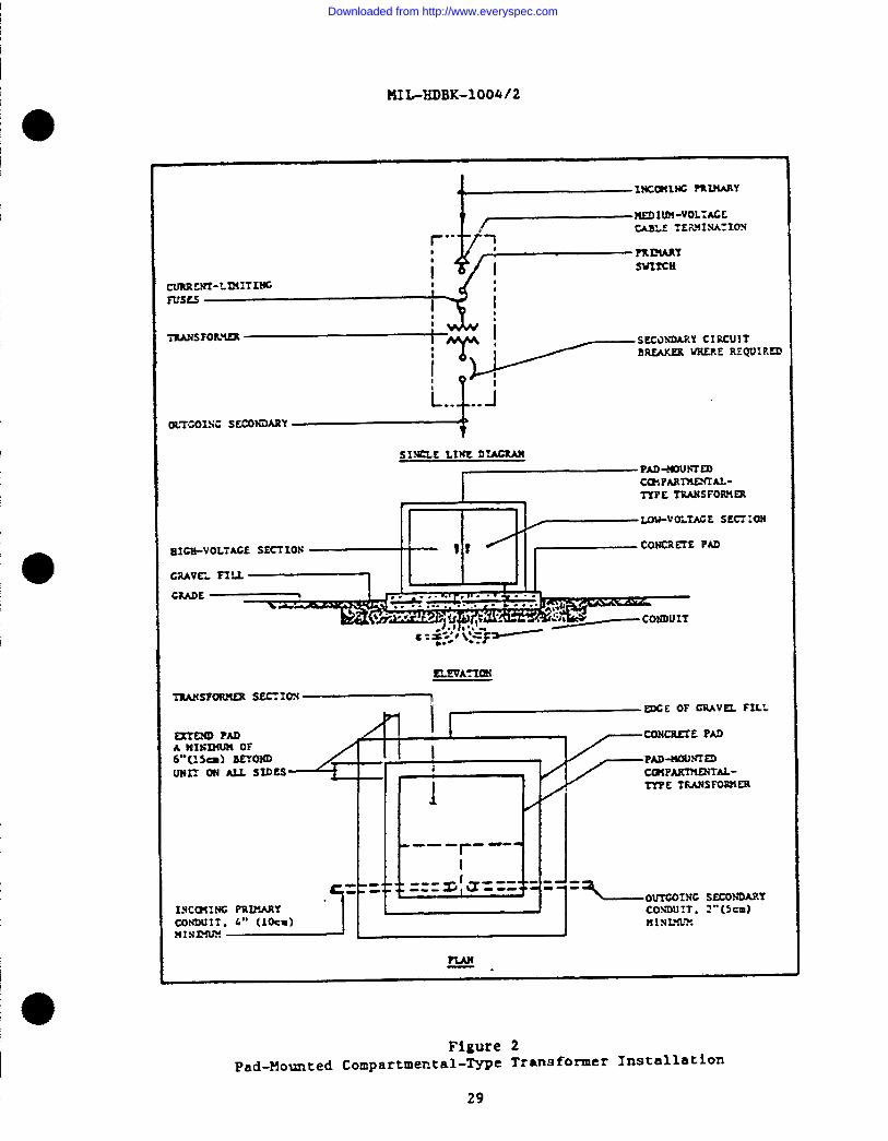
HN#-3DBK-loo4/2
Orroo’xrxSECONIIARY
Figure 2Fad-Mounted Compartmental-&pe Transformer Installation
29
Downloaded from http://www.everyspec.com

MIL-HDBK-1004/2
ASY
RED
Cu
CUVA11OII stcONms.Y
CONWI1,4“(1-)MININTIW
“c-’ ‘“’” ——————— r------~::”PAD si2ALL n-rsmA lam Llws 0?
0uTC4TW SLTION
12,, (30+ BeYom
WIT on NJ. SIDES‘~,, (ld MI”IWJM
m
/ mR Ilrrf#N.—
mcmrw1 I I .J_ LLF.I11OII 07 rilol
PRrlUET CIS!SDU1lb c. .Z ,,:
KUJc5PJ-
mvAsLE
4 ‘
L12An Csn’rs=
P-3’(Lm) niIUMUM TO
6, (-) WCMUWM \ SIDE 0? S?XX1ON ,
UP 70 25 kV4,(1 -1/4m) MIIIIMUP
ItPnr2shs.T TO FSOST 07 SE.TIO
8’(2.5=). M2SIIPIVM
%,5 I=— mcE
PRISIM1 .
3.(b) HxnmI
1I ‘A
]C(lm) MI NIHUS!
UTE UIDTu
QBDrrFOR CRLWNDING
sEE PICURE 4
~
lSOTE: ?ILWRZ 1S SUWN ?OR AS SXS2’SXOR 1NSTALLA11ON. SIKSIAS FUR
LH7ER1OR1NSTALUTIONESCSF7 F04CE ENCLOSUP.I v2LL BE MALL
or SUIUIINC. CDNCRFIE PAD, mc .. WLL UC ~R s~ ~VEUT1IATIOS , LIGHTING, ETC. , 1S NECSSSAR~ .
Figure 3
Radiai-Type Articulated Secondary Unit Substation installation
30
Downloaded from http://www.everyspec.com

MNAIDBK-1004i2
10
I
1’
LoADCENTm
Cmmrtm Wm!
e Pa
ML)
GiiE sm.EIJ — ~A#!)YRAMSFC$$WM “?42 / ~cATECASE CROWD
?LM
Figure 4
Secondary Unit Substation Croundin13
31
Downloaded from http://www.everyspec.com
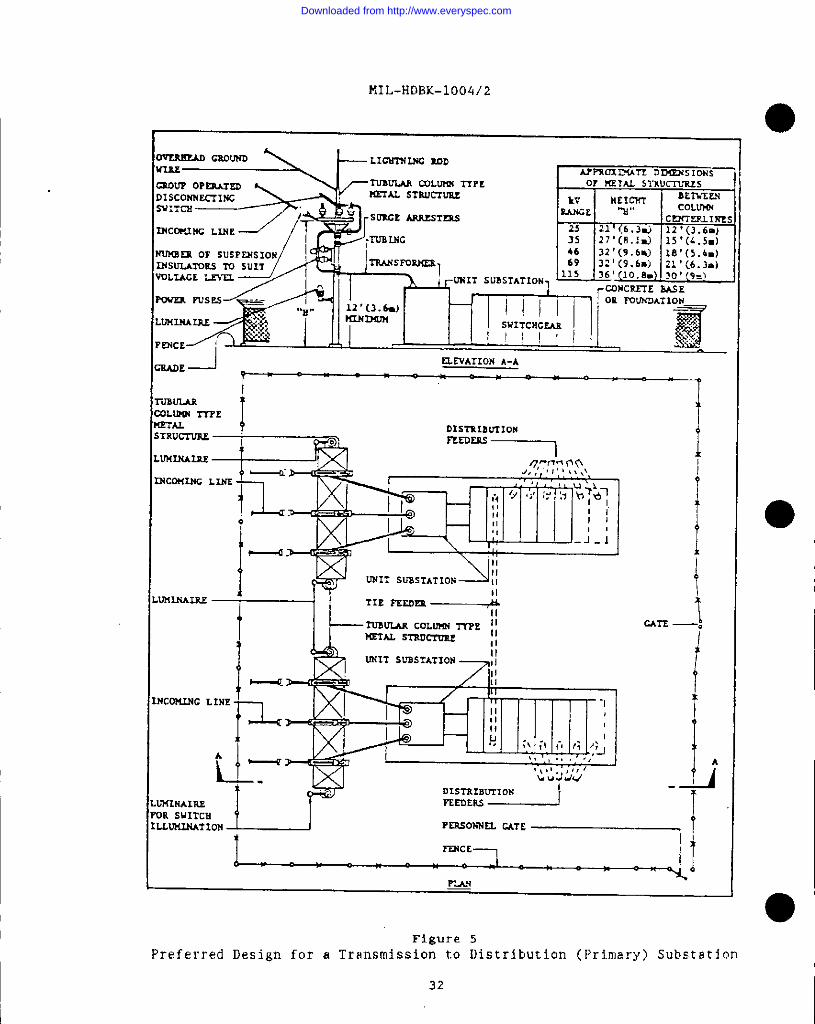
MI L. HDBK-1004/2
I
0— Gsoulm —LICSIWLNC MD
mow Oemm nm.rn.An munm m~ 0? PmTu srluL-rLrsrs
DISCONS~INC
SW:TCS
~= OF SUSPESS1ON
rxsuxms m SUIT
YQLIACE LET’U.
LLWIA13J
GsArE -J amATION A-A
? Y
I,, , .x.x,-l:,=,,=Ii
rmcr,
J]
Figure 5
Preferred Design for a Transmission to Distribution (Prl.mary) Substation
32
Downloaded from http://www.everyspec.com
5.2,2.1 ~ounti~.on channels or other
MIL-H’DN(-1004/2
Provide e eoncrtte base. Substation should be mountedsupports which are flush with the top of the base.
5.2.2.2 $Hlort-circuitDuty. Circuit interrup~ing devices shall becoordinated with each other. Bach device shall be capable of clearing themsximum fault available, Ilraci~ for bus bars and other current-carry$ngparts should be capable of withstanding the mechanical stresses produced bythe maximum available short-circuit current, .
5*2.2.3 w Rrotectio~ Air-type load interrupter switches withcmrremt-limltimg fuses shall”be used, unless other protection such as circuitbreakers or liquid-type switches are more appropriate. Use of circuitbreakers may be required to provide sufficient interrupting duty, or becausecoordinated tripping 5s required. Circuit breakers are more reliable thanswitches, WC their additional cost must be justified. Use of Hquid-ismersedwitches k appropriate far certain installations, such as in undergroundvaults.
5.2.2.4 Utlliltlt PzotectiOQ, Coordinate lightning protection with othercomponents of the distribution system that may be exposed to surge voltages.Provide arresters when necessary. When dry-type transformers with lower BI’Lratings are wsedj extra protection may be required.
5.2.2.5 ondam PrOtection. Protection shall use either metal-enclosed~low-voltage power or molded-case circuit breakers. Normally for buildingservices, molded-case units are used for less than 11200 A and low-voltagepower wmits,are used for higher amperages. For shore-to-ship service, lowvoltage power units are required.
5.2.2.6 ~trwmentati$in . Unit substations of more than 500 WA must beprovided with at least an ammeter and a secondary volbmeter. The use ofvattmeters (recording or indicating) and voltmeters~ for primary servicemetering, will depend on the individual installation. For provision ofwatthour demand meters with pulse initiators see requirements for energymonitoring in this section.
5.2.3 anizememt~. Use standard arrangements where possible. Standardnnic substations have the primary switch on the left, the transformer in themiddle, the circuit breakers on the right, and space for future additions.
5.2.3.1 ~ * Where conditions dictate otherwise, the reversedarrangement may be adopted.
5.2.3.2 P ble Endee,- . Use double-ended unit substations where two primarysources are”~equired to provide reliability. See Figure 6 for a layout of asecondary-selective-type double-ended arrangement. Bach transformer and itsassociated equipment shall be capable of carrying the essential loads of bothsections. In most cases where double-ended substations are installed, such asfor communication loads, the essential load will comprise the entire facilityload. In sizing the transformers, cake into consideration allowableoverloading. Refer to ANSI C57.91, C57.92, or C57,96, for overloading. “Wherethe normal double-ended unit substation is used, the designer shall providefor contemplated future expansion; this arrangement does not permit additionof unexpected future circuit breakers. For appl~catlons where future
33
Downloaded from http://www.everyspec.com

MI L-HIIBK-1004/2
.. -—.-/ I II 1’ .l___l. II
(3Smw LINE rm.wJ4(3 FLOOR ?l_4s
1~ .4s mQUIRED TO PROVUK NEC nowmc spAcE
o lNC.3M1NC “LDIu?I -VOLTWE SERVICE - ‘IWO SERVICE REQUIRED
@FEEDER TIE. PROVIDE bWEN ONE FEEDER WILL BE AVA1L4JLE
ON1.Y AT A mm E DATE
SPARE DUCTS
PLLLBOX (1F RSQU1m)
PRIMARY LOAD INTERRUPTER SWITCH AND CUW.ENI-LIMITING !WSM
?-EDIWH-v0L7ME C&SLE 1!! DUCT
THREE-PHASE TPANSmm
I.OW-VOLTMZ SWIT~C~ SWT1m
SECOmaT )L4.111CIRCUIT BUS WITH AVXILMY ALARM CONTACTS
TIE CIRtL!lT BSUX2R lNKR1.OCKED WITH UIN CIRCUIT n~
L.OV-VOLiKE W.E7ER5
Figure 6
Secondary-Selective-Type Articulated Secondary Unit Substation Installation
34
Downloaded from http://www.everyspec.com

I MIL-MDBK-1004/2
I
expansion may be greater than normal, or unpredictable, consider two otherarrangements requiring more floor area and initial co~t, but which permit easyaddition of sections, or replacement of transformers wlch larger wnits. Onearrangement has the pri,mary~transforming and secondary sections for eachhalf in separate lineups, with a tie bus or conduit and wire connecting thetwo. The tie breaker may be in either lineup. The ocher arrangement has the
primary and transforming sections, alo~ with the secondary main breakersseparate from the aecondmy lineup.
5.2.3.3 Secondarv Stlot-1’#etwor~.Use secondary spot-network unit substationsfor Ioade requiring an unusually high service reliability where the f.ncreaeedcost can be justified. Figure 2 would represent a secondary spot-networksubstation with a two-transformer input to a multiple-feeder output, if thetie circuit breaker were eliminated and the secondary main circuit breakerswere shown with network protectors. ThiEJsystem is the most reliable powersupply for large Ioada, since any fault on the primary input ta the secondarybus is automatically disconnected by the network protector operating at aspeed which greatly minimizes voltage dips from faults or large transientloads. The extra cost of the additional transformers and network protectorsplus possible increased secondary duty ratings from the Increased short-circuit capacity of parallel transformers makes this a very expensiveinstallation, especially when in the usual case, three or four transformersare paralled.
5.2.4 allatiomq. Indoor unit substation transfonnera of thedry-type may be used and need not be installed in vaults. Less-fluxnable,liquid-insulated umfta may be installed without a vault where permitted byNFPA 70. Where vault~ are reqwired for less-flammable, liquid-insulatedtransformers in some cases and in all cases for oil-insulated transformers,their installation shall conform to NFPA 70. An economic or functionaljustification must be provided for the type of unit provided. Select theinsulation type on the basis of surrounding atmosphere and basic impulseinsulation level required. Check loading characteristics from ANSI C57.91,C57.92, or C57.96 makimg sure that the lower impulse level standardly providedfor dry-type units are adequately protected. Equipment shall conform toNAVFAC !WGS-M465.
S.2.4.1 lln7-Tvne_ Conventional-ventilated, epoxy-encased-ventilated(cast resin), or gas-fil;ed are all considered dry-type units. Normally theconventional-ventilated type, as the least costly, shall be installed.However, consider utilizing the epoxy-encased type for units which serve in astand-by status. Conventional units readily absorb moisture when notenergized and need special handling when re-energized; epoxy-encased types domot. Epoxy-encased types can be considered to be better braced for short-circwit duty since the epoxy entireXy supports the coils. Gas-filled typesshould be restricted to hazardous area Iocatlons, if such units camnot belocated outside the dangerous area.
5.2.4.2 ‘rvnew . Only less-flammable, liquid-irtsulatedand oil-insulated units shall be installed. Askarel-imsulated and nonflammable,fluid-insulated are not permitted.
S.2.4.3 tiorlCoqlpati * For a comparison of the various transformerinsulations refer to Table 6. Cost percentages given first are for indoor
35
Downloaded from http://www.everyspec.com

MI L-HDlll:-loc14/’2
Table 6
Comparison of Types of Transformer Insulation
I LIQUID-INSULATED
Impulse stiength (BIL) 1 OOY*
Temperature rating 55°0r 6~C
Audio sound Isvel 2. X dB
Weight . . . . . . . . . . . i 007.
Dimensions . 100%
Application . . . . . . . . m.rldoo~
Maintenance normal
cost . . . . . . . . . . . . 237% (100?
Oil
LEss-LAMMABLl
1007.
,5°0r 65°(
X dB
12070
100Y.
a II
normal
200% (13(
‘ONVENTIONA1
Variesl
80 ‘or 150°C
X+IO dB
80%
100%
indoor
frequent
125% (127Y0
Conventional
DRY - lYPE
EPCXY -
ENCASED
Vanesi
10°0r 15(FC
X+IO dB
95Y.
10570
all
normal
200Y, (200%
GAs -flLLED
Variesl
120°c
X+1O dB
125%
120%
all
minimum
!20% (220”/.)
1 V~eS fTOm 33 to”66 percent depending on voltage level. Higher BIL ratings for dry - trPe *~~O~er
are available, but at& increased cost for conventional and gas - filledtypes.
2X indicates normsl decibel level for liquid - immersed unts.
3Indoor SISO in fire - resistant vautts when morn economical U-m other types.
locations. Second cost percentages given in parentheses are for outdoor
locations.
36
5,2.5 Unit Substation Roonw. Unit substation rooms shall not contain any
pipes, ducts, or other foreign systems, except thOse required for fire
protection, ventilation, and drainage of the room; however, dry-type units may
be installed without a separate room if piping is not mm immediately over
such units.
5.2 .5.1 Drainage. Rooms containing liquid-insulated transformers shall be
provided with concrete curbs and an appropriate drainage. system to prevent
liquid from spreading to adjscent rooms. Use the criteria ic NFPA 70 for unit ●substation room.
Downloaded from http://www.everyspec.com

I5.3.2.1 units O KiloVolt~eres and Sma~. Units are noz provided witheither taps or a minimum percent impedance unless specified. To preventexcessive interruptin@jduty on secondary equipment it may be necessary tocheck manufacturers’ ranges of available impedances~ as there is no industry
?IIL-MDBK-100412
5.2.S.2 &x!%&E. Equipment rooms where primary switching equipment,than transformer switching, ie imtalled shall have riotless than twoaccess doors for use by authorized persomel only.
otherseparate
5.2.5.3 ~ . Provide venc%lation adequate to d%ssipate heat givenoff by transformers and associated e~uipmenc and to maintain safe operatingtemperatures. Gravity ventilation 5.susually not adequate for indoorsubstation rooms; in such cases, mechanical ventilation should be provided. Inair-conditioned buildings, am economical and positive mems of ventilatingsubstation rooms is to eXhsust tempered air from conditioned spaces throughthe substation room.
5.2.5.4 w. If local conditions require less than UEMA TR-1 recommendedaudio sound levels, an economic comparison should be made between the cost oftranafmmers having lower than standard noise levels~ and the coat of soundand vi!bratlomSsolation of the transformer room. Avoid locating unit
substation rooms near critical spaces requiring low noise levels, such asauditoriums, sick bays~ or living quarters (refer to HAVFAC lE1-1.03,
AcoUR!JW ●
5.2.5.5 werfi~ . Provide emergency Ii$htlmg, of the ba&tery-operated type, in unit substation rooms.
5.3 on volt- su~ * Material and equipmentshall be based an NAVFAC NFGS-16335. Generally transformers shall be grade-mowmted type subject to the limitation given Zn this section. Transformersmay be pole-moumted type only when such transformers comply with the .requirements given in Section 2.
5’.3.1 ~econda~ Utit Substation l!v~e~. Secondary unit substations shouldgenerally follow the criteria given previously for indoor unit substationsexcept that requirements for outdoor installations apply. Because these urd.tsare not tamperproof, substations must be protected from unauthorized access bychain link fencing of at least 7 ft (2.1 m) imlkeight as a minimumrequirement. Provide three strands of barbed wire above for additionalprotection only where such subataticm% are in housing areas or otherwiseexposed to military dependents or where required by the usix agency. Otherfence materials to provide equipment masking, sound absorption, or protectionagainst sabotage may he necessa~ in some cases (see Figure 3].
5.3.2 l?adMo~ted c~ta~-~ne Trams=er Uni,- tq. Units should beprovided in accordance with the requirements of MAVFAC MFGS-16462. Zhisspecification limits the primary protective options to group-operated, load-break switches. Since such umits are tamper resistant, they need not befence-enclosed (see Figure 2).
standard.
5.3.2.2 W s ~ar~et r than 500 kVA.larger than 500 kVA are available up
Pad-mounted units in three-phase unitsto a capacity of 2,500 kVA. These um$cs
37
Downloaded from http://www.everyspec.com
MIL-5iDBK-loo4/2
I
0are less expensive than secondary substation units. However, because primary
protective devices available for such larger sizes do not provide dead-front
load-break features within the pad-mount construction, the use of units larger
than 750 kVA is not recommended.
5.4 Outdoor Distribution Voltage Substations. Their design should meet
the criteria for acceptable power sources covered in NAVFAC DM-4. 1 and their
design shall meet the recomcmendationa of the Base Exterior Architecture (BEA)
plan.
5.4.1 Structure-Mounted Eaui Dment. Structure-mounted equipment should be
used for voltages above 35 kV. The use of modern low-profile metal structures
with tubular type or H-beam supports is considered the most desirable design.
The conventional lattice-type structure is unattractive in appearance, more
difficult to maintain, and ❑ ore vulnerable to the twisting forces from heavy
winds (see Figure 5) .
5.4.2 Transformers. Primary unit substations require less land space, are
visually less objectionable, and because of the integrated transformer to
secondary connection, are more reliable than separate substation transformers
and secondary protective devices.
5.4.3 Connection to Primarv Distribution Lines. An underground connection
from the rotation to aerial lines should be provided when distribution voltage
is 35 kV or less. An underground line not only provides aesthetic enhancement
but reduces vulnerability to lightning or other weather or man- produced
interruptions.●
5.5 Substation Considerations. Consider the effects that the actual
site electrical configuration, type of incoming and outgoing switching, need
for supporting structures and surge protection, type of transformers, and
control features have on a substation layout.
5.5.1 Site Effects. In the design of a substation, consider the following
factors:
a) Architectural requirements; landscaping.
b) Exposure conditions; for example, at the seashore or in other
corrosion-producing atmospheres.
c) Physical conditions such as mow or ice, sandstorms, altitude,
and lack of rainfall.
d) Adjacent terrain and installations affect landscaping layout and
noise treatment. Utilize the influence of the direction of prevailing winds
on sound propagation to minimize noise exposure (refer to fiAVPAC DM-1 .03) .
5.5.2 Electric Confi.euration. Determine the electrical configuration with
the respect to provisions for adequate station capacity plus supply and feeder
circuit conditions. Consider supply circuit requirements for the following
conditions: ●a) single or multiple supplY,
b) supply circuit. voltage. and phases,
38
Downloaded from http://www.everyspec.com
c)d)
For feeder or
%)b)c)d)
NIL-HDIW-100412
overhead or under~round supply requfred, andprimary switching.
load circuits, determine the following conditions:
number of circvits,capacity of circuits,voltage SIM phases andoverhead or underground distribution required.
Finally, consider coordination of circuit protective devices betweensupply and feeder circuits.
5.5.3 Jncomin~-b~ne Switching. Design the substation with a minimum ofincoming-line switching consistent with good maintenance and operation. Forrating of equipment, refer to MIL-HT)BK-1004/3,$witch~ear and Relaving. Also,consider the methods described in paras 5.5.3.1 through 5.5.3.3.
5.5.3.1 Circuit Breaker~. Circuit breakers should be utilized only when the
circuit interrupting or relaying requirements do not allow the use ofswitches. Provide a disconnect and bypass switching features where drawoutcircuit breakers cannot be utilized.
5.5.3.2 $witc& . Switches are covered in Section 2 of this handbook. Forvoltages of 15 kV or less, load interrupter or disconnect switches areavai2able. Load Interrupter switches disconnect circuits under fully loadedconditions and are therefore usually the most des5.rablechoice. Use .disconnect twitches only to interrupt transformer exciting currents. The useof disconnect switches is not recommended, except for primary incoming lineswhere secondary circuit ~-reakerscan interrupt loads. Assure that operatorsdo not open disconnect switches under load, either by interlocking with loadswitching equipment or by operating procedures.
5.5.3*3 @rremt LimitimK ?r~tectors. Current Limiting protection devicesare covered in Section 2. They are generally inappropriate for substation usewhere metal- enclosed or metal-clad switchgear for 15-kV applications providesa more desirable desi$n.
5.5.4 chJtb70imR-Peeder Switch=ear. For ratings and selection of equipment,refer to M,IL-XDBK-1004/3.
5.5.4.1 .@Ov and LeSs. For load circuits below 600 V, select from one ofthe following:
a} metal-enclosed (low-voltage power) circuit breakers wherereliability and the longer withstand rating period are desirable; or
b) molded-case circuit breakers. 1403.ded-casecircuit breakers mustbe further defined as to tripping and interrupting currents and whether fully-rated capability or other features are desirable. Xhe use of the term“insulated case” conveys no minimum requirements in accordance with anYrecognized industry specification and should not be used.
5.5.4.2 Over 600 volts. For load circuits over 600 V, use criteria in
39
Downloaded from http://www.everyspec.com

MIL-HCIBK-1004/2
MI L-HDBK–1004/3 to select from the follovi. ng:
a) either oilless, metal–clad, mediun-voltage circuit breakers,
preferably of the vacuum circuit breaker type; or
b) grounded, metal-tank type, frame-mounted circuit breakers, with
open disconnecting switches. Circuit breakers may be oil, gas, vacuum, or
compressed air type. Oil-insulated type shall be installed only in outdoor
locations and only for voltages exceeding 35 kV.
5. 5.5 Substati~_ Structures. Depending on the chosen design, the
substation structure may consist of the following:
a) flat concrete base without elevated structures, applicable for
underground supply and load circuits served by metal-clad switchgear;
b) steel or aluminum superstructures mounted on concrete piers; or
c) s combination of either of the aforementioned systems.
5.5.6 Tr ansformers
5.5.6.1 Selection. Consider the types of insulation that are suitable for
the site and the system voltages (see Table 6). Select oil-insulated for
outdoor applications, except where fire safety considerations require the use
of less-f lsmrnable, liquid-insulated insulation which is not usually available
for voltages above 34.5 kilovolts. For indoor installations, see theo
paragraph on transformer insulations of this section.
5.5.6.2 Cooling. Forced cooled ratings are only available on larger size
transformers and the designer should check their availability before
specifying. Dependent upon stsndard ratings and overlosd capacity
calculations, specify the cooling method from one of the following:
a) self-cooled, type OA,
b) one-stage forced-cooled, type FA,
c) two-stage forced-cooled, type OA/FA,
d) one-stage double-forced-cooled; forced-oil, forced-air, type
FOA, or
e) triple-rated, types OA/FA/FOA/ or OA/FA/FA.
5.5.6.3 Transformer CaDa City. Choose the transformer rating by considering
the maximum load to be carried for normal and contingency conditions and the
possibility of accepting overloading with accelerated loss of system life.
5.5.6.4 Fire Protection. For minimum safe distsnces of transformers to
buildings and other fire protection criteria refer to MIL-HDBK-1OO8. Also
refer to IEEE 979, Guide for Substation Fire Protection.
5.5.6.5 Transformer Noise. Specify transformer noise levels as given in
NSNA TR-1. When standard noise levels are found to be too high, estimate the
cost effectiveness of sound minimizing methods such as:o
a) specifying a transformer vith a lower noise level,
40
Downloaded from http://www.everyspec.com

MIL-IUIBK-100J%/2
b) util,$zi~ sound barr~ers, orc) designing a sound-absorbing enclosure.
5.5.7 I?rotection* Where supply or load circuits are overhead orwhen equipment is located on elevated structuresfili&htn.ingprotection isrequired in all areas, except those with few lightning starms annually. Dataon the mean annual number of thunderstorm days in the continental UnitedSrates is given in NFFA 78, U@htti Pr tec~$o on,Code. Local practice forlightning protection should be followed. Install lightning rods on substationsuperstructures where required for lightning protection. Surge (lightning)arresters are required at all elevated structures for each circuit, forground-mounted equipment served by overhead lines and not vithin theprotective range of other arresters, and elsewhere where surges could damagee+qu~pment. Determine ratings of arresters according to the equipment to beprotected, impulse insulation levels of equipment, and the expected dischargecurrents the arrester must withstand. Arresters are designed to dischargesurges and are classed according LO their protective level. They areconstructed in various ways to provide nonlinear volt-time characteristics.The National Rural Electric Cooperative Association (NRECA) Research Project82-5, ~ PrOtlzction Planual for Rural Electric SVstems provides a eourceof information concerning lightning protection for distribution systems.
5.5.7.1 G.WMMS5. Select class of arrester based on the following guidelines:
e) Use station-class surge arresters on substations with incomingand outgoh.g aerial circuits above 15 kV.
b) Use intermediate-class surge arresters on substations withincoming and outgoing aerial circuits above 600 V to 15 W, except wherestation-class arresters are requ$red on transformer terminals to provideadequate protection.
C) Ike distribution-class arresters at substations where &hey .provide adequate protection for switchgear and as backup protection for
~ arresters locaced at tlxejunction of overhead and underground t,ncom2ngandoutgoing lines.
5.5.7.2 XYEW4. Arresters are deai~ed so that at power frequencies currentdoes not flow, but at a level of overvoltage which would damage systemInsulation, the arrester provides a low-impedance path to dhcharge Iig.bt’niuinduced or other high frequency power surges.
The silicon-carbide valve arrester has am element with nonlinearvolt-ampere characteristics which limits the follow current to a value thatthe series gap can Interrupt. This type is being phaaed ouc by manufacturers.
The metal-oxide varistor type arrester provides the most modernsolution to the problems resulting from surge voltages, since Its gaplessconstruction means there is no volt-time-gap sparkovez characteristic to beconsidered.
5.5.7.3 Additional Requirements. Also refer to NAVFAC DM-4.06 foradditional lightning protection criteria.
41
Downloaded from http://www.everyspec.com
MI L-HDBK-1004/2
5 .5.8
5.5.8.1
metering
5.5.8.2
Control Features
Instrumentation. Instrumentation should be in accordance with
and relaying requirements of MIL-HDBK-1004/3.
EnerxY Monitoring. Check 10CU1 energy monitoring requirements to
assist in energy conservation and appropriate i;ad sheddi~. in general ,
instrument transformers belonging to a utility company cannot be used for
❑ onitoring. Watthour meters at distribution substations should be of the
pulse initiator type . At utilization substations, it is suggested that
watthour meters be provided with the pulse initiator feature, as the cost is
not excessive, While the use of instantaneous and peak demand vattmeters for
all transformers larger than 500 kVA is recommended, actual provisions should
be those required by the activity. Aa a minimum, always provide at all new
distribution substations, conduit installed to the location selected for a
future monitoring panel from the following points:
a) energy sensing instrument transformers,
b) a 120 V power source, and
c) a communication line tie-in.
5.5.8.3 Control Cables. For control cables refer to IEEE No. 525, Guide for
the Selection and Installation of Control and Low-VoltaRe Cable Svstems in
Substatior&.
5.6 Substation Workin.e Space and Access Requirements. Indoor and ●outdoor substation layouts shall provide safe working space and access to meet
the requirements of NFPA 70 keeping in mind any need for installing and
removing equipment, vehicle accesa necessary for outdoor substations, and
adequacy of floor or foundations to support equipment weights.. .
5.6.1 ~. Adequate space must be allocated early in the
programming/plartning stages. Future expansion space should be clearly
delineated as should safety exit requirements. Interior space for substations
is always at a premitun, which can be further minimized by the intrusion of
structural elements or installation of mechanical equipment . Electrical
requirements are often underestimated.
5.6.2 Existing Construction. When electrical upgrading of existing
COn.9trUCti0n is involved, the. design must take into account any extra space
and costs required to meet current NFPA 70 code requirements. Working space
and access requirements have become more stringent as successive codes are
issued and many existin.s vaults or substation installations may not ❑ eet
current criteria. If the design cannot meet current NFPA 70 requirements,
then a waiver must be obtained from the proper authority.
5.7 Grounding. Provide a grounding electrode system for each substation
and connect equipment and system groundg so as to provide persmnel and
equipment protection and grounding continuity.
5.7.1 Grounding Electrode Svstems. Provide electrode systems made of
either the girdle or grid type using horizontal conductors running between
vertical around rods.●
42
Downloaded from http://www.everyspec.com

o
II
~
!0I
I
P
0
MI L-HDBK-loQA/2
5,7.1.1 Girdle TWe. Use ~irdle type systems for pad-mountedcompartmental-type transformers and secondary unit substations (see Figure 4).
S.7.1.2 ~~. For the much larger voltage @radients at substations forutility-ltavyinterconnections utilize the grid-typet buried groundingnetwork. Mesh spacirqyzof 10 to 12 ft (3 to 3.5 m) are commonly used andnormally such spacings can control surface voltage gradfents even though theground resistance may be relatively high.
5’*7*~*3 ~* See recommendations of IEEE 80, Guide forfetv @ Substation roundi~ ● Where the local utility or activity indicates
the Epecial grounding techniques are necessary because of poor soilconductivity, their recommendations should be followed. Refer to IEEE 142,Recomm~ded Practiee for Ground~ of Crc$al Power Svstemsfor a discussion of soil resistivity. Refer to l?AVFACRFGS-16302 for maximum
allowable ground resistance valves.
5.7.2 ~auimment Grou?l~ . Metallic enclosures, including cases ofprimary and secondary switchgear and transformers, shall be grounded toprotect operating personnel.
5*7*3 ast’~ G~oWUUIW . Ilnleesfunctional requirements prohibitgretrnding,611 transformers shall be provided with wye-connected neutralconnections grounded independently at each voltage level, that is~ at thetransformer aecomhary.
5.7.3.1 New ral GrounQ.@t ,0 lTo&mlly, provide solid grounding, since this isthe least expensive method of limiting transient overvoltage while obtainingsufficient ground fault current for selective tripping. Provide impedancegrounding only when required to limit ground fault currents to acceptablevalues or where required by code, such as for portable substations or to matchexisting eystem de~i~n. Refer to RAVFAC DM-4.1 for additional requirements.
S.7.3.2 Ground-fault protection for each systemvoltage level is independent af the protection at voltage levels fortransformers connected delta-wye or delta-delta. A circuit breaker havingground fault protection can be set to operate for lower ground fault levelsand providee fast operation eince no downstream comxlination is required.Fuses have fixed t$me-current characteristics. On s~coridaryunit substations,low-voltage circuit breakers with ground fault tripping should he used onmains and on large or important feeder units as a minimum, if selectivity canbe achieved. On distribution aubstatfons, the additional cost for circuitbreakers must be justified on the basis that the improved selectivity isrequired for reliability. Refer to IEEE 242S ?Becomemded Practice foxJ?ratection,and CoordWon of In@striml and Commercial Power Svstems, forground fault protection application data.
5.7.4 CentinUity. The most important consfderat%on in groundingis assuring continuity of the grounding system, Special danger points such asmetal-strwcture mounted switches and surge arresters of transmission todistribution substations (see Figure 5) shall be provided with dual groundpaths. Ground wires run with primary feeder cables may bebecause of existing station practice Qr for other reasons.
43
required either
I
I
Downloaded from http://www.everyspec.com

MIL-HDBK-1004/2
o5.7.4.1 Fault Current , NFPA 70 requires a low impedance ground path for
fault currents. Where reliable low impedance paths for utilization
substations cannot be provided because of soil conditions, equipment
locations, or other factors, install a ground wire with the primary feeder
cable back to the distribution system substation.
5.7.4.2 Portable Substations. NFPA 70 requires that the exposed noncurrent-
carrying metal psrts of portsble substations must be connected with an
equipment grounding conductor run with the primary feeder back to the point
where the system neutral impedance is grounded. The reason for such a
requirement is that the mobility of the portable substation precludes a
predesigned grounding electrode system.
5.8 Safetv Considerations. Provide for public safety and for protection
of operating personmel with respect to the factors described in paras . 5 .8.1
through 5.8.5.
5.8.1 ESI@JZ3. Connect fencing, including gates , to substation grounding
(refer to FIIL-HDBK-1005/12, Fencing. Gates, and Guard Towers ) . For aesthetic
reasons, plastic-coated fabric may be used. Grounding this type of fabric
will require removing coating in order to get a good ground. A touch-up
plastic should recoat any uncoated areas not covered by the ground connection.
Application and material should be as recommended by the fence manufacturer.
5.8.2 petal Enclosu res. For personnel
enclosures around all live parts.
5.8.3 LocklnE of Gates, Provide locks
doors to prevent access to live parts.
5 .8.4 Bondin~ of Gates. For grounding
with bonding straps across hinges .
safety, use metal or fiberglass
●on gates. Interlock switchgear
purposes, gates shall be provided
5.8.5 &al iia mirri Sims. Legal warning signs are required on fences and
electrical equipment enclosure which are unfenced. Guidance for warning
signs in fs.mily housing and community center areas is given in fiEf4A 260,
Safetv Labels for Padmounted Switchgemr and Transformers Sited in Public Areas.
44
Downloaded from http://www.everyspec.com

I
CLASSIFIED LIST OF UNITS.
To Convert I?rm
MEA
f~2+, ,,**. **a** ,,~n2,+*..@,-r...- ●
Kim . . . . . . . . . . . . . .
LENGTH
ft . . . . . . . . . . . . . .ft . . . . * ● . . * * . ● . .in . . . . . . . . . . , . . .in . . . . . , . . . . .. . .mile (statute) . . . . . . . . .
LIGHT
foottxmm.es . . . . . . . ● . . .
M4ss
02 . . . *. . .* * . ● . ● *lb . . . . . . . . . . . . . .tori(short) . . ● . ● . . . . . .
MASS PER UNIT ARM
lb/ft2 . . . . . . . . .. . .lbiin~ (psi] . . . . - . . . .
TEMPERATURE
Degree Fahrenheit . . . . . . . .
NOTATION. Factors are written as
To
.**.* .*.
. . . . . .*,. . . . . . . .
. . . . . .**● ✎ ✎ ✎ ✎ ✎ ✎ ✎
✎ ✎ ✎ ✎ ✎ ✎☛☛
☛☛✎☛☛ ☛✎✎
● ☛✎✎✎ ● *O
,..., ● O’.
. ..** ● ☛☛
● ✎☛☛☛ ● ☛✎
✎ ✎ ✎ ✎ ✎ ✎ ✎ ✎
..,.0 **.*
. . . . . **..
Multiply By
9.290E-026.452E+QQ5.067E-01
3.04SE-043.048E-022.540E+QD2.540E-011.609E+QQ
1.076E+OQ
2.835E+OI4.536E-019.072E+02
4.882E+Q07.031E+02
degree Celsius , . . . t“C=(t0~32)/1.8
a number greater than one and less than tenwith three decimal places. This number is ~ollowed by the letter E (forexponent), a plus or minus symbol, and two digits which indicate the power of10 by which the number must be multiplied to obtain the correct value. Forexample:
5.067E-01 %s 5.067x10⁻¹ or 0.5067
S%milarly: 2.835E+01 is 2.835%101 or 28.35
45
Downloaded from http://www.everyspec.com

l.lIi.-HnnK-1004, I2
AWG
20
18
16
14
12
13
8
6
I 4
2
1
1/0
2/0
3/0
4/0
AMERICAN WIRE GAGE (AWG) CON’vTRSIOti
kCM
1.02
1.62
2.58
4.11
6.53
lC.4
16.5
26.2
41.7
66.4
83.6
105.6
133.1
167.8
211.6
0.5170.8231.312.083.315.268.3713.321.233.642.453.567.485.0107.0
0
,.
46
Downloaded from http://www.everyspec.com

o
0
0
PIIL-HDBK-1004/2
REFERENCES
ANSI Standards. Americ n ~ala Stmdard8 I.mtltut% (ANSI), 1430 Eroadway,New Ya~It,Ml!10018.
ARSI C2-8Y
ANSI C29.I-82
AHSI C29.2-83
A?WI C29.3-86
M?SI C29.4-84
AMSI C29.5-84
ANSI C29.6-84
AMI C29.8-85
ANSI C29.9-83
ANSI C37.30-71
ANSI C37.32-72
AHSI C57.12.00-80
ANSI C57.U.01-79
MIS1 CS7.12.20-81
National Electrical Safety Code
Test Methods for Electrical Power Insulators
Insulators, Wet-Process Porcelain andToughened Glass, Suspension Type
Wet-Process Porcelain
Wet-Process Porcelain
Wet-Process PorcelainMedium-Voltage Types
Wet-Process PorcelainPin Type
Wet-Process PorcelainLine-Post Type
Wet-Process PorcelainCap and Pin Type
Wet-Process PorcelainPost-Type
Insulators, Spool Type
Insulators, Strain Type
Insulators, Low- and
Insulators, High-Voltage
Insulators, High-Voltage
Insulators, Apparatus
Insulators, Apparatus
Definitions and Requirements for High-VoltageAir Switches, Insulators, and Bus Supports
Schedules of Preferred Ratings, ManufacturingSpecifications, and Application Guide forH@h-Voltage Air Switches, Bus Supports, andSwitch Accessories
GerteralRequirements for Liquid-ImmersedD5str3.bution,Power, and RegulatingTransformers
Gameral Requirements for Dry-Type Distributionand Power Transformers
Requirements for Overhead Type DistributionTransformers, 500 kVA and Smaller: High-Voltage 67,000 Volts and Below; Low-Voltage15,000 volts and Below
I47
Downloaded from http://www.everyspec.com
fiIL-lH)BK-lo04/2
ANSI C57 .91-81
hNSI C57 .92-82
Guide for Loading Mineral-Oil-Overhead and
Pad-Mounted Distribution Transformers Ra:eti
500 kVA and Leee with 65 Degrees C or 55●
Degrees C Average Winding Rise.
Guide for Loading Mineral-Oil-Immersed Pover
Transformers up to and Including 100 MVA with
55 Degrees C or 65 Degrees C Win?ixg Rise
ANSI C57.96-59 Guide for Loadiig Dry-Type Distribution and
Power Transformers
ANSI C62.1-84 Surge Arresters for AC Power Circuits
ANSI C62.2-81 Guide for Application of Valve-Type Surge
Arresters for Alternating Current Systems
ANSI C62.33-82 Varistor Surge Protective Devices
Electrical Transmission and Distribution Reference Book, Central Station
Engineers, Westinghouse Electric Corporation, Pittsburgh, PA 15230, 1964
Electrical Utility EnE ineerinx Reference Book. Distribution Systems,
Electrical Utility Engineers, Westinghouse Electric Corporation, East
Pittsburgh, PA 15230, 1965.
Engineering and Desizn Criteria for Na.r? Facilities, Military Bulletin - 34}
available from Naval Construction Battalion Center (code 156), port Hueneme,
CA 93043. ●
Industrial Power Systems Handbook, Donald Beeman, Editor, McGraw Hill Book
Company, New York, NY 10020, 1955.
Institute of Electrical and Electronic Enzineers (IEEE), 345 East 47th Street,
New York, NY 10017. The following publications are IEEE Standards.
IEEE 18-80 Shunt Power Capacitors
IEEE 80-86 Guide for Safety in Substation Grounding
IEEE 100-84 IEEE Standard Dictionary of Electrical and
Electronics Terms
IEEE 1.41-86 Recommended Practice for Electric Power
Distribution For Industrial Planta
IEEE 142-82 Recommended Practice for Grounding of
Industrial snd Commercial Power Systems
IEEE 525-78 Guide for the Selection and Installation of
Control and Low-Voltage Cable Systems in
Substations
IEEE 979-84 Guide for Substation Fire Protection
48
Downloaded from http://www.everyspec.com

t!IL-HDBK-lC)94/2
IEEl?/ICEA P-46-426 Power Cable Ampaci.ties, 1962
NESC Handbook by Allen L. Clapp, 3984
cam Handboaks~ available from Naval Publications and Forms Center, S801Zabor Avenue, Philadelphia, PA 19120.
WL-WEK-419 Ground$ng, BondiW, and Shielding farElectronics Equipment and Facilities in TwoVolumes, 21 January 1982
MIL-MDBK-1004/3 Switchgear and %elaylng
MIL-HD$K-loo4/4 Electrical Utilization Systems
MIL-HDBK-1005/l.2 Fencing, Gates, and Guard Towers
MIL-HDB1C-1OO8 Fire Protection for Facilities Engineering,Desi&n, and Construction, April 1985
#IIL-MDBK-1025/2 Dockside Utilities
MIL-HDBK-1190 Fec$lity Planning andI September 1987
Hatiomal Electrical Ma~acturer~ Association n (l’?EMA),Washington, M 20037.
Design Guide,
2101 L Street, ~.!?.,
NEMA 260-82 Safety Labels for Padmounted !hritchgearandTrazmformers Sited in Public Areas
NEMA HV-2-84 Application Guide for Ceramic SuspensionInsulators
NEMA SG-2-81 High-Voltage lhases
NEMA SG-13-83 Automatic Circuit Recloser$, Automatic LineSectionalizes and Oil-pilled CapacitorSwiwhea for Alternating Current Service
NE51ATR-1-80 Transformers, Regulators and Reactors
E ti~ma~ Fire Prote~t~ (NF?A), Batterymarch Park, Quincy, MA;i269.
NI?PA24-84 Insta%latien of Private I?ireService Fla%msandTheir Appurtenances
NFPA 70-87 National Electrical Code
MFPA 78-86 Lightning Protection Code
Naval I’acili ties Enmineerm Command (I?AVFAC)
DM-1.03 Architectural Acoustics
49
Downloaded from http://www.everyspec.com

MI L-ilDBK--i OO4i2
DM-4 .1
DM-4 .05
DM-4 .6
DM-4 .09
DM-7. G2
DM-11.1
NFGS-02225
NPGS-16301
NFGS-16302
NPGS-16321
NFGS-16335
NTGS-16462
NPGS-16465
P-442
Preliminary Design Considerations
400-Hertz Medium-Voltage
Conversion/Distribution and Lov-Voltage
Utilization Systems
Lightning (and Cathodic) Protection
Energy Monitoring and Control Systems
Foundations and Earth Structures
Tropical Engineering
Excavation, Backfilling, and Compacting for
Utilities
Underground Electrical Work
Overhead Electrical Work
Interior Transformers
Transformers, Substations and Svitchgear,
Exterior
Pad-Mounted Transformers
Interior Substations
Economic Analysis Handbook
Department of Defense activities maY obtain copies of Design Manuals and
P-Publications from the Commanding Officer, Naval Publications and Forms
Center, 5801 Tabor Avenue, Philadelphia, PA 19120. Department of Defense
activities roust use the Military Standard Requisitioning and Iesue Procedure
(MILSTRIP) , using the stock control number obtained from NAVSUP Publication
2002.
Other Government Agencies and commercial organizations may procure Design
Manuals and P-Publications from the Superintendent of Documents, U.S.
Government Printing Office, Washington, DC 20402.
50
Downloaded from http://www.everyspec.com
It
o
~
1’
I
,0
~I
KIL-HllBX-lC104/2
~ECA Research Proiect. !iationalRvr 1 l?l.ectric CooDerative Assoc5&tion, ,1800 Massachusetts Avenue .lW, Wash&ton, DC 20036. *
NRECA 82-S-83 Lightning Protection Manual for Rural Electr~csystems
Overhead e ConstructionU, General Order No. 95, State of California, Public~tili~ies Commission, Sacramento. CA 95820.
Rural Electri,fication Administration/U.S, Deuartment of Anr~cu~tmr@ (REA),South Agricultural Building, Room 1017, Washington, DC 20250
REA 65-2 Evaluation of Large Power Transformer Losses,April 1978
rd lhuvll?~okf r Elec rical~o t , Donald G. Fink and H. Wayne Beaty,Editorsr NcGraw-Hill Book Company, New York, NY 10020, Eleventh Edition.
llnder~round Svstems Reference Book, EEI No. 55-16, Edison Electric Institute,Hew York, NT 10016, 19S7.
United Stat~s Arnv ma af~ , Headquarters publications Deposit,Commander, US~GPC, 2800 Easterm Boulevard, Baltimore, MD 21220
TM 5-852-5 Arctic and Subarctic Construction, Utilities,October 19S4
.
CUSTOINAMNAVY-YD
PREPARING ACTIVITYI’?AVY- YD
PROJECT HO.FACR-0232
I
51
Downloaded from http://www.everyspec.com