military handbook combination locks - cdse · to mil-imbk-lo13/8 s1december 1989 military handbook...
TRANSCRIPT

●
t
o
MIL-ImBK-lo13/8
S1 DECEMBER 1989
MILITARY HANDBOOK
COMBINATION LOCKS
AMSC NIA
DISTRIBUTION STATEMENT A. APPROVED FOR PUBLIC RELEASE: D1STRIBUTION ISUNLINIITED
AREA FACR

MIL-HOBK-1013/8
.
.
THIS PAGE INTENTIONALLY LSIT BLANK
ii
●
.
.
●

●MIL-KDBK-1013/8
ABSTRACT
This ❑ilitary handbook provides current information and guidance oncorrect procedures to follow for the installation, operetion, and❑aintenance of mounted combination locks and combination padlocks. Thishandbook addresses both key -chenge and hand-change locks.
.
I
o
iii

MIL-tIOBK-1013/B
.
I
THIS PAGE INTENTIONALLY LEFT BLANK ●✚
I
iv

II
MIL-HDBK-lo13/8
●
i.
I
This handbook has been developed from an evaluation of facilities in the shoreestablishment, from surveys of the availability of new materials and construc-tion methods, and from selection of the best design practices of the NavalFacilities Engineering Command (NAVFACENGCDli) , other Government agencies, andthe private sector. This handbook was prepared using, to the maximum extentfeasible, national professional society, association, and institute standards.Deviations from these criteria in the planning, engineering, design, andconstruction of Naval shore facilities cannot be made without prior approvalof NAVFACENGCOM HQ Code 04.
Design cannot remain static any more than can the functions it serves or thetechnologies it uses. Accordingly, recommendations for improvement areencouraged and should be furnished to Commanding Officer, Naval CivilEngineering Laboratory, Code L30, Port Hueneme, CA 93043; telephone (B05)982-1693.
TH15 WDBOOK SHALL NOT BE USED AS A REFERENCE DOC~ENT FOR PROC~MENT OFFACILITIES CONSTRUCTION . IT IS TO BE USED IN THE PURCHASE OF FACILITIESENGINEERING STUDIE5 AND DESIGN (FINAL PIANS, SPECIFICATIONS, AND COSTESTIMATES) DO NOT REFERENCE IT IN MILITARY OR FEDERAL SPECIFICATIONS OROTHER PROCUREMENT DOCUMENTS
●
i.
I v

NIL-NOBK-1013/8
CriteriaManual
MIL-HD13K-lo13/l
DM-13.02LANTDIV
MIL-HDBK-lo13/3
MIL-NDBK-lo13/4
MIL-HDBK-lo13/5
PHYSICAL SECURITY CRITERIA NANuALS
~
Physical Security of Fixed Land-BasedFacilities
Commercial Intrusion Detection Systems (IDS)
Bolt-On Installation and Checkout Procedures NCELFor The High-Security Hasp With Or WithoutAnti-Intrusion Bar Cover
Instruction for Design, Fabrication, and NCELConstruction/Installation of SecureEnclosures
Steel-Ply Wall Hardening Selection and NCELInstallation Guide
I
vi

MIL-ROBK-1013/8
●
I
‘o
.
I,.
●
Section 11.11.2
Section 22.12.1.12.1.22.1.32.22.2.12.2.2
Section 33.13.23.2.1
3.2.23.2.2.13.2.2.23.2.2.33.2.2.43.2.2.53.2.2.63.2.33.2.3.13.2.3.23.2.3.33.2.3.43.2.3.53.2.3.63.2.43.2.4.13.2.4.23.2.4.33.2.4.43.2.4.53.2.4.63.2.53.2.5.13.2.5.23.2.5.3
COMBINATION LOCKS
CONTENTS
mssINTRODUCTION .........................................Scope ................................................Purpose ..............................................
GENERAL ..............................................Combination Lock= ....................................Group land lR Locks .................................Mounted Combination Locks.. ..........................General Operating Guide lines ..........................Class ification .......................................Mounted Combination Locks.. ..........................Combination Padlocks .................................
KEY-CHANGE LOCKS ....................................Genera l.............................................Sargent & Green leaf Mounted Combination Locks. .......Combination Change Keys for the R6700, 8400, and8500 Series, aswelles the8470MP ...................8400 Series ..........................................Opening Procedure ....................................Securing Procedure. . .............................Combination Changing Procedure. ......................Installation Procedure ...............................Torque Adjustment ....................................Maintenance Recommendations. .........................8500 Series ..........................................Opening Procedure ....................................Securing Procedure ..................................Combination Changing Procedure. ......................Install ation Procedure ...............................Torque Adjustment ...................................Maintenance Recommendations. .........................R6700 Series .........................................Opening Procedure ....................................Securing Procedure ...................................Combination Changing Procedure. ....................Installation Procedure ...............................Torque Adjustment ...................................Maintenance Recommendations. .........................8470MP Deadbolt With Combination Lack. ...............Opening Procedure (84oo and 8500 Series) .............Securing Procedure ...................................Combination Changing Procedure. .....................
111
33333446
555
57999101213131314141621212122222425262627282831
vii
I

MIL-RDBK-lo13/8
EM!?
3.2.5.43.2.5.53.2.5.63.2.5.73.2.5.83.33.3.13.3. 1.13.3. 1.23.3.1.33.3. 1.43.43.4.13.4. 1.13.4. 1.23.4. 1.33.4. 1.43.4. 1.53,4. 1.63.53.5.13.5. 1.13.5.1.23.5. 1.33.5. 1.43.5. 1.53.5.23.5.2.13.5.2.23.5.2.33.5.2.43.5.2.5
Section 4.4.14.24.2.14.2. 1.1‘$.2.1.24.2. 1.34.2. 1.44.2. 1.5
Strike Installation .................................. 32Lock Installation Procedure (8400 Series). ........... 32Lock Installation Procedure (8500 Series) ............ 33Torque Adjustment .................................... 36Maintenance Recommendations .......................... 36Sargent & Greenleaf Combination Padlocks. ............ 368077AB ............................................... 36Opening Procedure ................................... 3BSecuring Procedure ................................... 3BCombination Changing Procedure. ...................... 38Maintenance Recommendations .......................... 40La Gard Mounted Combination Locks .................... 401980-A RL ............................................ 40Opening Procedure - Factory-Set Combination. ... ..... 40Opening Procedure - Previous ly Set Combination. ...... 42Securing Procedure ................................... 42Combination Changing Procedural....................... 42Installation Procedure. .............................. 44Maintenance Recommendations. ......................... 4SMosler Mounted Combination Locks ..................... 45MRK 120.............................................. 45Opening Procedure .................................... 4SSecuring Procedure ................................... 46Combination Changing Procedure. ...................... 46 ●Installation Procedure. .............................. 49MaintenanceR ecommendations. ......................... 50MRK 302-402 .......................................... 50Opening Procedure .................................... 51Securing Procedure ................................... S3Combination Changing Procedure ....................... 53Installation Procedure ............................... 54Maintenance Recommendations. ......................... ss
HAND-CHANGE LOCKS .................................... 56Genera l.............................................. 56 .
Mosler Mounted Combination Locks. ... ..... ........ 56MR 302-402 ........................................... 56Opening Procedure .................................... 58Securing Procedure ................................... 58Combination Changing Procedure. ..................... 58Installation Procedure. .............................. 59Maintenance Recommendations.. ........................ 61
viii ●

●MIL-HDBK-1013/8
,0
I,.
Figure 1234
56
78
9
1011
12
13
lb
1516
17
lB
1920212223
24
252627
28
29
ExKe
FIGURES
Comparison Between the 6720 and 8400 Change Keys. ......Backplane With Flat Surface. ...........................Backplate With Raised Circular Area. ...................Backplate With Raised Circular Area and RecessedKeyhole ...............................................Backplate With Slightly Recessed Circular Area. ........Front View, Sargent and Greenleaf 8400 Series MountedCombination Lock .......................................Exploded View, Sargent & Greenleaf 8400 Series Lock. ...Sargent & Greenleaf 8400 Series With Back CoverRemoved ................................................Front View, Sargent and Greenleaf 8500 Series MountedCombination Lack ......................................Exploded View, Sargent and Greenleaf 8500 Series Lack.Sargent & Greenleaf 8500 Series With Back CoverRemoved ................................................Sargent & Greenleaf 8500 Series, Dial, Dial Ring,and Spindle ............................................Sargent & Greenleaf 8500 Series, Drive Cam withSpline Key Inserted ....................................Front View, Sargent and Greenleaf R700 Series MountedCombination Lack .......................................Exploded View, Sargent & Greenleaf R6700 Series Imck. ..Sargent & Greenleaf R6700 Series With Beck CoverRemoved ................................................Front View, Sargent & Greenleaf Model 8470MP Deadboltwith Combination Lock... ...............................Rear View, Sargent & Greenleaf Model 8470MP Deadboltwith Combination Lack.. ................................Sargent & Greenleaf 8470MP, Strike No. 1...............Sargent & Greenleaf B470MP, Strike No. 2...............Sargent & Greenleaf 8470MP, Strike No. 3...............Sargent & Greenleaf 8470MP, Strike No. 9...............Sargent and Greenleaf Model 8077AB CombinationPadlock ................................................Front View, La Gard Model 1980-A RL MountedCombination Lock .......................................Exploded View La Gard Model 1980-A RL. .................Change Key for the La Gard Model 1980-A RL. ............La Gard 1980-A R48 Back Plate With ChangeKey Inserted ..........................................Front View, Mosler Model MRK 120 Mounted CombinationLock ...................................................Exploded View, Mosler Model MRK 120....................
566
66
78
12
1415
17
19
20
2223
27
29
2930303030
37
404143
43
4647
ix

MIL-HLIBK-1013/8
30 Chame Kev for the Mosler Model
●EM!?
MRK 120 ................ 4931 Mos l~r Mo~el MRK 120 Backplate With Change Key in
Inserted Position ...................................... 4932 Front View, Mos ler Model MRK 302-402 Mounted
Combination Lock ....................................... S133 Exploded View, Mosler Model MRK 302-402 ................ 52 .34 Change Key for the Mosler Model MRK 302-.402............ 5535 Mosler FISK302-402 Backplate With Change Key in
Inserted Posit ion...... ................................ ss .36 Front View, Mosler Model MS 302-402 Mounted
Combination Lack ....................................... 5637 Exploded View, Mosler Model MR 302-402 ................. S738 Mosler MR302, Wheels .................................. 60
TABLE
Table 1 Types of Combination Locks. ............................ 2
RSFSRENCES ............................................................ 63
●

MIL-HDBK-1013/8
I
I
I
Section 1: INTRODUCTION
1.1 -. This handbook provides basic instructions for theinstallation, operetion, and maintenance of various mounted combinationlocks and combination pedlocks. Also included sre detailed instructions forchanging and setting combinations for hand-change and key-change combinationlocks and combination padlocks. A list of locks included in this handbookis found in Table 1, along with other pertinent information.
As noted in Table 1, not all of the locks are currently availablefrom the Defense Industrial Supply Center (DISC) However, those no longerstocked were at one time procured in large quantities, and are included inthis military handbook. Whila the Sargent & Greenleaf 8500 Series and theMosler Models NRK 302-402 and MRK 120 were not distributed by DISC, theywere procured in large numbers direct from the manufacturer.
1.2 Purvose. This military handbook is for uae by all personnelresponsible for the installation, operation, and ❑aintenance of ❑ountedcom~inat ion locks and combination padlocks
I
I
1●

MIL-ROBK-1013/8
Table 1Types of Comb ination Lacks
National Stock Combinat ion
Lock Number (NsN) Change Type Description
Sargent & Greenleaf Available from Key-change Mounted lock,
R6700 Series local S&G Group 2distributes
Sargent & Greenleef Key-change Mounted lock,8400 Series 5340-00-264-7592 Group lR
Sargent & Greenleaf Aveilable from Key-change Mounted lock,8500 Series (Note 2) local S&G Group lR
distributors
Sargent & Greenleef 5340-00-671-6607 Key-change Mounted lock,
8470FIP 5340-01-183-5952 Group IR,Deadbolt withCombination Lock
Mosler Available from Key-change Mounted lock,NR(K) 302-402 manufacturer and hand - GIOUP lR
(Note 1) change
Mosler NRK 120 Available from Key-change Mounted lock,manufacturer Group 1(Note 1)
I,aGard Model Key-change Mounted lock,1980A RL 5340-00-905-4953 Group lR
Sargent & Greenleef Pad lock Provides8077AB Steel Sheckle 5340-00-285-6523 Key-change low level of8077AB Brass Shackle 5340-00-285-6524 security
Notes:1. Locks, dials, and dial rings must be ordered separately.
2. The 8500 Series locks are evailable from Sargent & Greenleaf withGroup 1 wheels , but these locks ere not to be used on securitycontainers due to possibility of radiological ettack.
I
2

I
I
o
MIL-HDBK-lo13/i3
Section 2: GENERAL
2.1 Combination Locks. A combination lock is any lock that requiresthe use of one or more movable lettered or numbered dials to align the lockcomponents to open the lock. Mounted combination locks are those attachedwith screws or bolts to the container, door, or equipment that the lockssecure. Combination padlocks are removable from the container or equipmentthat the locks secure.
Combination locks have many components that interrelate with eachother. The wheels are the components inside the lock that must be slimedcorrect ly to open the lock. O: mounted combination locks and ❑any -combination padlocks, the dial is the ❑ovable metal or plastic part on thefrent of the lock used to turn the wheels. The wheels, spacers, and washersconstitute the wheel pack. The internal components of the lock are housedin the lock case. On a mounted lock, a dial ring and dial are on the frontof the door or drawer head between the dial and the lock case. The boltprojects from the case and prevents the door or drawer from opening.
2.1.1 Group 1 and lR Locks. The Group 1 and lR locks addressed in thishandbook meet the requirements of MIL-L- 15596 Series, Locks, Combination(Safe and Safe Locker) . Group 1 locks have brass wheels, whereas Group lRlocks have X-ray proof (Delrin) wheels. Each lock has a thermal relockdevice for protection against forced entry using thermal devices. Theselocks, along with the Sargent & Greenleaf R6700 Series (Group 2), have aspecial relocking trigger for protection against punching of the spindle.If an attempt at penetration is made through either of the above-mentioned❑eans, the trigger will automatically deadlock the unit.
2.1.2 Mount ed Combination Locks. Each mounted combination lock isavailable with either a front-reading dial or top-reading (“spy proof”)dial. The top-reading dial permits only the person dialing the combinationto see the numbers involved. Each lock is furnished with a spindle that canbe cut to suit varying thicknesses of doors or drawers. The spindles anddrive cams are designed to allow the locks to be mounted in the right-hand,left-hand, vertical-up, or vertical-down positions.
2.1.3 General Operating Guidelines . When operating combination locks orsetting combinations, always observe the following rules:
a) Never spin or jerk the dial. Always turn the dial slowly andevenly, stopping exact ly on each number of the combination.
b) Passing a combination number requires restarting the entirecombination sequenca from the beginning.
c) Never use force. If a lock fails to operate or operates withdifficulty, request assistance from a qualified locksmith.
3

I
MIL-HDBK-1013/8
●d) Never close a door or drawer after setting a new combination
until the new combination is worked at least three times a“d is recorded inaccordance with security directives.
e) On a mounted three-wheel lock, there are 1,000,000 possiblecombinations. Some combination padlocks have as many as 125,000 possiblesettings. However, because of mechanical and psychological factorg, not al1of these combinations are valid. Specifically, follow these guidelines:
(1) No two numbers should be closer than exactly five digitsapart, or multiples of ten.
(2) The third number should not range from O to 20 or from 85to 100,
(3) Do not use straight ascending or descending combinations.Examp 1es : 41-56-71, 81-58-30. It is better to use a sequence that is HIGH-LOW-HIGH or LOW-HIGH-LOW. Examples: 72-23-81, 33-67-38.
(4) All three numbers should not be even
(5) All three numbers should not be odd
(6) Never set a 50-25-50 combination (the standard factorycombination sequence) on the lock of a container that holds classifiedmaterial. when removing a container from service, set combination to ●50-25-50.
(7) Do not use significant dates (birthdays, anniversaries,etc. ), street addresses, telephone numbers, etc. , ss the basis forcombinations.
(8) When locking a safe, door, or cabinet, turn the dial atleast four full revolutions in one direction.
2.2 Class ificatiq
2.2.1 Mounted Comb hat ion Locks. Underwriters Laboratories’ Standard UL768, Standard for Combination Locks, classifies mounted combination lc,cksaseither Group 1, Group lR, or Group 2. To qualify for a Group lR rating, alock must be manipulation, radiographic, and thermal resista”t. Group 2combination locks must be reasonably resistant to unauthorized opening.
2.2.2 Combination Padlocks. Combination padlocks are classifiedaccording to Federal Specification FF-P-11O (Saries) , Padlock, ChangeableCombination (Rasiatant to Opening BY Manipulation and Surreptitious Attack).

I
1.
MIL-HOBK-1013/8
Section 3: KEY-CHANGE LOCKS
3.1 General. Key-change locks require no disassembly to set newcombinations. To change the combination, the change key provided with thelock is inserted into a keyhole in the back coverplate. Some key-changelocks hsve two reference marks on the disl ring. At the top of the dialring is the opening index. A changing index may be either slightly to theleft or to the right of the opening index, depending on the model. When skey-change lock has only one reference mark, the single mark is used as boththe changing and opening indexes. Before the combination of any lock ischanged, read the entire change procedure careful ly. Read installationinstructions thoroughly before beginning an installation procedure.
3.2 Sargent & Greenleaf Mounted Combin8~n Locks
3.2.1 Combination Change Keys for the R6700, 8400, snd 8500 Series, aswell ss the 8470MP. To change the combination, these locks require one oftwo different chsnge keys (see Figure 1). For the four different backplate(back cover) styles, see Figures 2 through 5. The installed backplate styleon a particular lock will determine the required change key. The firststyle, as shown in Figure 2, hss a flat backplate. The second, shown inFigure 3, has a reised circular area. As depicted in Figure 4, the thirdhas e raised circular area with a recessed keyhole. The fourth, shown inFigure 5, has a slightly recessed circular area.
The backplanes ehown in Figures 2, 4, and 5 use tbe 6720 changekey. The 6720 key measures approximately 1-3/16 inches (30 mm) from the tipof the key to the shoulder. The backplate shown in Figure 3 uses the 8400chsnge key. The 8400 change key measures approximately 1-7/16 inches (36mm) from the tip to the shoulder. Figure 1 illustrates the difference inlength between the 6720 and B400 change keys. Using the incorrect key willcause the lock to malfunction, requiring the repair services of a locksmith.
Figure 1Comparison Between the 6720 and 8400 Change Keys
5

MIL-HDBK-1013/8
Fi~ure 2 Figure 3Backplate With Flat Surface Backplate With Raised Circular Area
Figure f+Backplate With Raised Circular
rLgu Le >Beckplate With SlightlyRecessed Circular AreaArea and Recessed Keyhole
m,----- c
●
●
●

MIL-HDBK-lo13/8
I
I
I
3.2.2 8400 Series. These combination locks are Group 1 or lR locksdesigned to provide resistance against surreptitious opening by manipulationthrough the sense of touch, sound, “reading,” electronic listening, and onGroup lR models, radiological attack. These locks are equipped with theuniversal “centi-spline” dial. This dial has a removable spindle that canbe positioned to any one of 100 settings that correspond with the dialgraduations. This permits the spline to be positioned to any handcondition. Each model is available with or without a metal tube that issecured to the lock case and simplifies installation by accurately aligningthe dial ring index with the lock. It also protects the spindle from doorinsulation.
Some 8400 Series locks have a torque adjustment feature that
applias precise pressure to the wheel pack to guard against vibrating or
“walking” the wheels into alignment. The torque adjustment allows the dialtorque to be adjusted to individual touch. An 8400 Series lock isillustrated in Figures 6 and 7.
Figure 6Front View, Sargent & Graenleaf 8400 Series Mounted
Comb ination Lock
7

MIL-HDBK-1013/8
8

o
.
3.2.2.1 Opening Procedure.Combination Iock, proceed as
a) Turn the dialcombination is aligned with
b) Turn the dialaligned the third time.
c) Turn the dialthe second time.
d) Turn tbe dial
It
I
1
1
MIL-HDBK-1013/8
To open a Sargentfollows:
H’T, stopping when
& Greenleaf 8400 Series
the first number of the:he OPENING index the fourth time.
{IGHT, stopping when the second number is
;EFT, stopping when the third number is aligned
?IGHT to O. Hold the dial in this position.
e) Turn the arrow knob (butterfly) in the center of the dialRIGHT as fer as it will go
CAUTION
Ensure that the dial is held at O when turningthe arrow knob during opening and closing.Internal spring damage can occur, requiringlock to be replaced.
f) Turn the dial to the RIGWr until it stops. The bolt is nowfully retracted.
3.2.2.2 Securing Procedure. To secure the 8400 Series lock, release thearrow knob by turning it to the LSP’T, then turn the dial tO the LEm atleast four complete revolutions.
3.2.2.3 Combination Changing Procedure. To change a combination setting,begin by selecting a new three-number sequence based on the rules presentedin paragraph 2.1.3e. Record the new combination in accordance with securitydirectives and proceed as follows:
a) Open the lock as described in paragraph 3.2.2.1.
b) With the door or container open, throw the dOOr/drawer bolt tothe locked Dosition. If the container has a bolt interlock, it will benecessary to depress the interlock plunger before the bolt can be thrownwhile the unit is ooen. Use the procedure recommended by the unit’smanufacturer.
c) l-brow
3.2.2.2.
d) Usingdial LSFT, stopping
the locking bolt by using the procedure in paragraph
tb”eCHANGING index and the old combination, turn thewhen the first number is aligned the fourth time.
9

MIL-HDBK-lo13/8
e) Turn the dial RIGHT, stopping when the second number isaligned the third time.
f) Turn the dial LEFT, stopping when the third number is alignedthe second time. Hold the dial in this position.
g) Fully insert the appropriate change key in the keyhole in the Iback of the lock (reference paragreph 3.2. 1). Rotate the key one quarterturn LEFT. This will unlock the wheels 1)0 not force the key. .1
NOTE .
On some containers, it may be necessery toremove a cover or door panel to expose theback of the lock.
h) With the key in this position, turn the dial at least fo,~rcomplete revolutions to erase the old combination.
i) To set the new combination, turn the dial LEFT, stopping whenthe first number of the new combination is aligned with the CHANGING indexthe fourth time,
j) Turn the dial RIGHT, stopping when the second number is Ialigned with the CHANGING index the third time. ●
k) Turn the dial LEFT, stopping when the third number is al.[gnedwith the CHANGING index the second time. Hold the dial in this position.
1) TI1rn the change key RIGHT and remove it from the lock. Thenew combination is now set.
m) Work the new combination at least three times with the door orcontainer open. If the lock cannot be opened using the new combinat ion, itcon be assumed that the new numbers were not set correctly. If this is thecase, cal 1 a qualified locksmith.
3.2.2.4 Installation Procedure. To install a Sargent & Greenleaf 84(10
Series Combination Lock, proceed as follows:
a) Using the template (provided with lock) , position lock indesired location.
b) Using the template, drill and tap four holes in mounting platefor the lock-attaching screws (1/4-20). Drill hole in mounting plate forthe spindle shaft (O.813-inch (21-mm) diameter if lock has a tube,0.625-inch (16-mm) diameter if it does not),
.
I
10
I
●

.
MIL-HDBK-lo13/8
c) Make sure the bolt is in the locked or engaged position. Toaccomplish this, rotate the dial left to O. Turn the arrow knob in thecenter dial to O, and rotate the dial left four revolutions, stop at arandom posit ion.
d) Remove the back cover of the lock.
If your lock is equipped with a tube, proceed with step e) below. If not,proceed to step i).
Insert tube and hold lock a~ainst mountinfi Dlate. Place dialring on tube
f)
K)
h)
i)
-.and lightly tighten tube nut.
Measure tube excess leaving 1/16 inch (2 mm) above tube nut.
Remove lock and cut off excess tube.
File end of tube smooth.
Securely fasten lock to mounting plate by installing the fourlock-attaching screws and tightening.
j) While aligning hole through door, fasten dial ring to doorusing acrewa and tighten tube nut (if present on lock) .
k) Insert dial into dial ring and hold snug.
1) Measure and cut off excess spindle from the wheel post,leaving 1/16 inch (2 nun) above the wheel post. Remove burrs.
m) Screw the drive cam on spindle until snug, then back off untilkeyway lines up. Insert the spline key with the key handle pointing awayfrom the center of the cam (see Figure 8). Drive the spline key incarefully. If the spline key becomes loose, the lock will not functicmproperly. Make certain that the spline key is tight.
fromease
NOTS
Before screwing dial/spindle into the drive camfor the final time, lubricate the dial, dialring, and drive cam bearing surfaces. Sargent& Greenleaf recommends G-322L lubricantmanufactured by General Electric. NSVSR useoil- or petroleum-based lubricants.
n) Cut off amount fromthe spindle. Spindle excessof measurement.
inner spindle equal to the amount removedcan be inserted over inner spindle for
11

0) Rotate dial to O
MIL-RoBK-lo13/8
and the arrow knob to O.
P) Insert the inner spindle. Make sure the tip of tbe innerspindle seats properly into the hole in the cam slide (see Figures 7 and 8).
q) Attach the back cover using the cover ❑ounting screws. Thelock is now ready to have the new comb in~tion set.
ADJUSTING
LO
SCREW
CAMSLIOE
WHEELS
KER
KEY
Figure 8Sergent & Greenleaf 8400 Series With Back Cover Removed
3.2.2.5 Torque Ad Iustment. To adjust torque on locks equipped with anadjusting screw, remove the back cover and insert a 3/32-inch allen wrenchinto the adjusting screw (reference Figure 8) Turn clockwise to tighten orcounterclockwise to loosen.
NOTE?
Adjustment should not be less than 18 inch-ounces (O.13 N,m) nor more than 24 inch-ounces(O.17 N.m) of dieling torque (8 slight drag onthe diel). Whenever lock torque is changed,the combination must be reset.
12
●

MIL-HOBK-1013/8
3.2.2.6 Maintenance Recommendations. Periodic servicing will extend the
life of the lock snd is essential for ❑aintaining proper security. Eschtime the combination is changed, inspect the lock for wear, metal filings,drilled holes, cracks, or any other visual signs of attempts to defeat thelock by forced entry techniques. The inspection. process should entailremoval of the back cover of the lock, and visual examination of esch wheelpart, as well as the cam and lever assembly, to make sure nothing is worn ordamaged. If lubrication is required, use molybdenum-d isulfide (powder)NSVSR use oil- or petroleum-based lubricants on combination locks.
NOTS
For Sargent & Greenleaf Combination bcks, themanufacturer recommends using GE-322L lubricsntmanufactured by General Electric.
Each time the back cover is removed, the combination should bereset. Remember to check the combination st least three times beforelocking the container.
Any maintenance other than changing the combination and inspectingthe lock should be referred to a qualified locksmith.
0 3.2.3 8500 Series. These combination locks are Group 1 or lR locksdesigned for added protection egainst most modern methods of attack, whilealso providin~ simplicity and ease of operation. Each ❑odel is availablewith Or witho~t a metal tube that is secured to the lock case and simplifiesinstallation by accurately aligning the dial ring index with the lock. Italso protects the spindle from door insulation.
Some 8500 Series locks have a torque adjustment feature that
applies precise pressure to the wheel pack to guard against vibrating or“walking” the wheels into alignment. The torque adjustment allows the dialtorque to be adjusted to individual touch. An 8500 Series lock isillustrated in Figures 9 and 10.
3.2.3.1 Opening Procedure. To open a Sargent & Greenleaf 8500 SeriesCombination Lock, proceed as follows:
1.a) Turn the dial
combination is aligned with
b) Turn the dialaligued the third time.
c) Turn the dialthe second time.
LE~, stopping when the first number of thethe OPENING index the fourth time.
RIGRT, stopping when tbe second number is
LSFT, stopping when the third number is aligned
d) Turn the dial RIGHT to O.
13

MIL-HDBK-lo13/B
NOEXCHANGINGINDEX
Figure 9
Front View. Sar$zent & Greenleaf B500 Series Mounted
e) Withactivate the lever
f) Turn
Comb ination Lock
zero aligned with the OPENING index, push the dial IN toassembly, release dial.
the dial RIGHT until the bolt is fully retracted.
3.2.3.2 Securing Procedure. To secure the 8500 Series lock, turn the dialto the LEFT at least four complete revolutions.
3.2.3.3 Combina tion Changing Procedure. To chrrnge a combination setting,begin by selecting e new three-number sequence based on the rules presentedin paragraph 2.1.3e. Record the new combination in accordance with securitydirectives and proceed as follows:
e) Open the lock as described in paragraph 3.2.3.1.
b) With the door or container open, throw the door/drawer bc)lt tothe locked posit ion. If the container has a bolt interlock, it will benecessary to depress the interlock plunger before the bolt can be thrownwhile the unit is open. Use the procedure recommended by the unit’s
I
I
●
manufacturer.
14

1’
,,
● 15

MIL-HDBK-lo13/8
c) Throw the locking bolt by using the procedure in paragraph3.2.3.2.
d) Using the CHANGING index and the old combination, turn thedial LSFT, stopping when the first number is aligned the fourth time.
e) Turn the dial RIGHT, stopping when the second number isaligned the third time.
f) Turn the dial LSFT, stopping when the third number is alignedthe second time. Hold the dial in this position.
g) Fu1lY insert the appropriate change key in the keyhole in theback of the lock (reference paragraph 3.2. 1). Rotate the key one quarterturn LSFT. This will unlock the wheels. Do not force the key.
NOTS
On some containers, it ❑ay be necessary toremove a cover or door panel to expose theback of the lock.
h) With the key in this position, turn the dial at leaat fourcomplete revolutions to erase the old combination.
i) To set the new combination, turn the dial L5PT, stopping when ●the first number of the new combination is aligned with the CHANGING indexthe fourth time.
j) Turn the dial RIG~, stopping when the second number isaligned with the CHANGING index the third time.
k) Turn the dial LSIT, stopping when the third number is alignedwith the CHANGING index the second time. Hold the dial in this position.
1) Turn the change key RIGHT and remove it from the lock. Thenew comb ination is now set.
m) Work the new combination at least three times with the door orcontainer open. If the lock cannot be opened using the new combination, itcan be assumed that the new numbers were not set correctly. If this is tbecase, call for a qualified locksmith.
3.2.3.4 Installation Procedure. To install a Sargent & Greenleaf 8500Series Combination Lack, proceed as follows:
a) Using the template (provided with lock), position lock indesired location.
16

●
.
a
I
!0
MIL-RDBK-lo13/8
b) Using the template, drill and tap four holes in mounting platefor the lock-attaching screws (1/4-20). Drill hole in ❑ounting plate forthe spindle shaft (0.813-inch (21-mm) diameter if lock has a tube,O.625-inch (16-mm) diameter if it does not)
c) Remove the back cover of the lock.
d) Place the lock bolt in the locked or engaged position and theaccelerator spring in the loaded position (Figure 11 - Note: Do not removethe drive cam)
If your lock is equipped with a tube, proceed with step e) below. If not,proceed to step h)
e) Insert tube and hold lock against the mounting plate. Placedial ring on tube and lightly tighten tube nut.
f) Measure and mark tube excess from door. Remove the lock andadd 3.0 millimeters or 1/8 inch (to insert the dial ring bushing) and cutoff excess tube.
ACCELERATOR SPRING IN
h
RELEASEO POSITION
ACCELERATOR SPRING INLOAOED POSITION
LOCK CASE ~
IHEELS —
CREW
BOLT INENGAGED(LOCKED)POSITION
CAM ~
L
~ REI_fJcKTRIGGER
TORQUEAOJUSTINGSCREW —
Figure 11Sargent & Greenleaf 8500 Series With Back Cover Removed
17

MIL-HDBK-lo13/8
g) Remove any burrs from the end of the
h) Securely fasten the lock to mountingscrews and tighten.
tube.
plate with four attuching
i) While aligning with hole in the door, lightly faaten dial ringto door using screws, and tighten tube nut (if present on lock) Dial ringopening index should be at 12 o’clock center position. Before installationof the dial ring, press the plastic bearing insert (Figure 12) into theopening in the back of the dial ring. The insert must fit flush with thedial ring. .
j) To install dial, hold the drive cam in place with one hand andthread the dial into the cam until the dial comes to a stop against th,>surface of the dial ring.
CAUTION
When threading dial into cam, do not allow camto slide outward against the accelerator spring.Accelerator spring can be easily damaged in thismanner.
k) The alignment of the dial and dial ring is critical to theoperation of the lock. Perfect alignment is necessary. The dial should beflush snd centered with the surface of the dial ring, for true center. o
1) Measure the excess spindle that projects beyond the drive cam.
m) Remove the dial, cut off excess spindle and remove burrs.
n) Tighten the dial ring screws
o) F’lace a washer, compression spring, and washer on hub of dial(Figure 12).
p) Insert dial into the lock (observe step j) CAUTION) Hold thedrive cam in place to receive nose of the drop lever and thread dial intocam until the dial stops
q) Rotate the dial counterclockwise a MINIMUM of one full turnuntil the spline in the spindle is aligned with the proper spline in thecam, the cam is positioned to receive the nose of the drop lever, and tbedial is on O.
18
I

MIL-HoBK-1013/8
.
.
Figure 12Sargent & Greenleaf S500 Series, Dial, Dial Ring, and Spindle
NOTS
If the lock is ❑ounted in the vertical-up orvertical-down position, the properly alignedspline should be ❑arked W/VO on the drivecam. For right- or left-hand mounting, RH/LHshould be aligned (reference Figure 13) .
r) Insert the spline key with the lip toward edge of cam. Tap inlightly. The dial must turn freely with no rubbing or interference.
NOTS
Before attaching cover to lock, check forproper in and out travel of dial foroperation of accelerator spring.
;0 19
I

MIL-RDBK-1013/8
SPLINE 1 ~SPINDLE
Sargent & Green leaf 85~0 Series, Drive Cam withSpline Key Inserted
s) Rotate the dial at least one complete revolution and stop ato. The accelerator spring should now be in the loaded position.
t) Hold the cover in place on the lock and push the diel in at O.Release the dial. Remove the cover and check the position of the acceleratorspring (spring should be in the released position). (If the acceleratorspring is not in the released position, the dial has not been backed out ofthe cam far enough and the condition ❑ust be corrected. Remove spline key,hold cam and rotate dial one additional full turn counterclockwise.Reinstall the spline key and repeat steps. )
u) Rotate the dial at least one complete revolution and stop at50. The accelerator spring should now be in the loaded position.
v) Hold the back cover in place on the lock and push the dial inat 50. The accelerator spring should not release. (If the acceleratorspring does release, the spindle must be turned clockwise into the cam onecomplete revolution and this step must be repeated. )
w) Dial the set combination (50-25-50) on the lock and observethe drop lever falling into the drive cam. Repeat this step at least threetimes
L20
.
.

.
.
MIL-HOBK-1013/8
x) When the accelerator spring is operating properly, the covermey be attsched to tbe lock and the new combination set.
3.2.3.5 Torque Ad iustment. To adjust torque on locks equipped with anadjusting screw, remove the back cover and insert .s3/32-inch allen wrenchinto the adjusting screw (see Figure 11). Turn clockwise to tighten orcounterclockwise to loosen.
NOTE
Ad Iustment should not be less than 18 inch-ounces..–(0.13 N.m) nor more than 24 inch-ounces (O.17 N.m)of dialing torque (a slight drag on the dial),Whenever lock torque is changed, the combinationmust be reset.
3.2.3.6 Maintenance Recommendations. Periodic servicing will extend thelife of the lock and is essential for maintaining proper security. Eachtime the combination is changed, inspect the lock for wear, metal filings,drilled holes, cracks, or any other visual signs of attempts to defeat thelock by forced-entry techniques. The inspection process should includeremoval of the back cover of the lock. and visual examination of each wheelpart, as well as the cam and lever assembly, to make sure nothing is worn ordamaged. If lubrication is required, use molybdenum-disu lfide (powder).NEVER use oil - or petroleum-based lubricants on combination locks.
NOTS
For Sargent & Green leaf Combination Locks, themanufacturer recommends using GE-322L lubricantmanufactured by General Electric.
Each time the back cover is removed, the combination should bereset. Ramember to check the combination at least three times beforelocking the container.
Any maintenance, other than changing the combination andinspecting the lock, should be referred to a qualified locksmith.
3.2.4 R6700 Series. These locks, commonly referred to as “R-Locks,”carry a Group 2 rating from Underwriters Laboratories. They are used onlyon money chests. The R6700 Series Locks have a torque adjustment featurethat applies precise pressure to the wheel pack to guard against vibratingor “walking” the wheels into alignment. l%e torque adjustment allows thedial torque to be adjusted to individual touch. The R6700 Series isavailable with or without a metal tube that is secured to the lock case and
21

MIL-HDBK-lo13/8
simplifies installation by accurately aligning the dial ring index with thelock It also protects the spindle from door insulation. A R6700 Serieslock is illustrated in Figures 14 and 15.
-,. ,
Front View, Sargent & Greenleaf R6700 Series MountedCombination Lock
3.2.4.1 QI?.QI@K prOcedure. To open a Sargent & Greenleaf R6700 SeriesCombination Iock, proceed as follows:
e) Turn the dial LEFT, stopping when the first number of thecombination is aligned with the OPENING index the fourth time.
b) Turn the diel RIGHT, stopping when tbe second number isaligned the third time.
c) Turn the dial LEFT, stopping when the third number is alignedthe second time.
d) Turn the dial RIGHT pausing momentarily at O, and continueturning until it stops. This retracts the locking bolt.
3.2.4.2 Securing Procedure. To secure the 6700 Series lock, turn the dialto the LEFT at least four complete revolutions.
22
●
.
●

MIL-HoBK-lo13/8
< -..4” ‘A__.J
23

MIL-RoBK-1o13/8
3.2.4.3 Combination ChanRing Procedure. To change a combination setting, —
begin by selecting a new three-number sequence based on the rules presentedin paragraph 2.1.3e. Record the new combination in accordance with securitydirectives and proceed as follows:
a) Open the lock as described in paragraph 3.2.4.1.
b) With the door or container open, throw the door/drawer bolt to ,the locked position. If tha container has a bolt interlock, it will benecessary to depress the interlock plunger before the bolt can be thrownwhile tbe unit is open. Use the procedure recommended by the unit’smanufacturer.
.
c) Throw the locking bolt by using the procedure in paragrspb3.2.k.2
d) Using the CHANGING index and the old combination, turn thedial LWT, stopping when tbe first number is aligned tbe fourth time.
e) Turn the dial RIGRT, stopping when the second number isaligned the third time.
f) Turn the dial LEIT, stopping when the third number is alignedthe second time. Hold the dial in this position.
g) Fu1lY insert the appropriate change key in tbe keyhole in the ●back of the lock (referenca paragraph 3.2.1 ). Rotate the key one quarterturn LRIT. This will unlock the wheels. Do not force the key.
NCYr2
On some containers, it may be necessary toremove a cover or door panel to expose the backof the lock.
h) With the key in this position, turn the dial et least fourcomplete revolutions to erase the old combination. .
i) To set the new combination, turn the dial LEFT, stopping whenthe first number of the new combination is aligned with the CHAMGING indextbe fourth time.
j) Turn the dial RIGRT, stopping when the second number isaligned with the CHANGING index the third time.
I
with thek) Turn the dial LEFf, stopping when the third number is aligned
CHANGING index the second time. Hold the disl in this position.
I

—1) Turn the
new combination is now
m) Work the
MIL-HDBK-1013/8
change key RIGHT and remove it from the lock. Theset.
new combination at least three times with the door orcontainer open. If the lock cannot be opened using the new combination, itcan be assumed that the new numbers were not set correctly. If this is thecase, cal 1 for a qualified locksmith.
*3.2.4.4 Installation Procedure. To install 8Series Combination Lock, proceed as follows:
,*a) Using the template (provided with
desired location.
Sargent & Greenleaf R6700
lock), posit ion lock in
four holes in mounting vlateb) Using the template, drill and tapfor the lock-attaching screws (1/4-20) . Drill hole in mounting plate-f~rthe spindle shaft (O.813-inch (21-mm) diameter if lock has a tube, O.625-inch(16-=) diameter if it does not).
c) Make sure the bolt is in the locked or engaged position.Depending on the ❑odel of your lock, this can be done by pulling the boltout with your fingers or by rotating the dial to the left four completerevolutions,
d)
If your lockI to step i]
I e)ring on tube
f)
g)
h)
i)
.
I
and stopping at random.
Remove the back cover of the lock.
is equipped with a tube, proceed with step e). If not, proceed
Insert tube and hold lock against mounting plate. Place dialand lightly tighten tube nut.
Measure tube excess, leaving 7/64 inch (3 mm) above tube nut.
Remove lock and cut off excess tube.
File end of tube smooth.
Securelv fasten lock to mountin~ Dlata bv installing the fourlock-attaching screws” and tightening.
-.
j) while aligning hole through door, fasten dial ring to doorusing screws and tighten tube nut (if present on lock).
k) Insert dial into dial ring and hold snug.
25

MIL-HDBK-lo13/8
1) Measure and cut off excess spindle from the wheel post,leaving 1/16 inch (2 mm) above the wheel post. Remove burrs.
m) Screw the drive cam onto spindle until snug, then back offuntil the appropriate slot in the drive cam lines up with the keyway of thespindle. Drive cam slots are labeled RH (right-hand), LH (left-hand), VO(vertical-up), and VD (vertical-down) for the four different mountingpositions [reference Figures 15 and 16). *
thekeythe
n) Insert the spline key with the key handle pointing away fromcenter of the cam. Drive the spline key in carefully. If the splinebecomes loose, the lock will not function properly.
#Make certain that
splint? key is tight.
NOTE
Before screwing dial/spindle into the drive camfor the final time, Iubricete the dial, dialring, and drive cam bemring surfaces. Sargent& Greenleaf recommends G-322L lubricantmanufactured by General Electric. NEVER useoil- or petroleum-based lubricants.
o) Attach the beck cover using the cover mounting screws. Thelock is now ready to have the new combi”at ion set. ●3.2.4.5 Torque Adjustment. To adjust torque, remove the back cover andinsert a 3/32-inch allen wrench into the adjusting screw (see Figure 16).Turn clockwise to tighten or counterclockwise to loosen.
NOTE
Adjustment should not be less than 18 inch-
ounces (O.13 N.m) nor more than 24 inch-ounces(O.17 N.m) of dialing torque (8 slight dragon the dial). Whenever lock torque is changed,the combination must be reset.
3.2.4.6 Maintenance Reconunendstions. Periodic servicing will extend thelife of the lock and is essential for maintaining proper security. Eachtime the combinat ion is changed, inspect the lock for weer, metal filings,drilled holes, cracks, or eny other visual signs of attempts to defeat thelock by forced entry techniques. The inspection process should Lmcluderemoval of the back cover of the lock, and visual examination of each wheelpart. as well as the cam and lever assemblv. to make sure nothin~ is worn ordama~ed. If lubrication is reauired, use ~~lybdenum-disu lfide (~owder)NSVE~ use oil- or petroleum-ba~ed lubricants on combination locks.
26

●MIL-HDBK-1013/8
. .
I
LOCK CASE rTORQUEAOJUSTINQ
7SCREW~ LEVER~ W= sCREu
SPINOLEKEY
WHEELS
CAM I L~ R94CK
SPINDLE TRIGGER
,0Figure 16
Sargent & Greenleaf R6700 Series With Back Cover Removed
NOTS
For Sargent & Green leaf Combination Leeks,the manufacturer recommends using GE-322Llubricant manufactured by General Electric.
Each time the back cover is removed, the combinationreset. Remember to check the combination at least three timeslocking the container.
should bebefore
Any maintenance other than changing the combination and inspectingthe lock should be referred to a qualified locksmith.
,0
3.2.5 8470MP Deadbolt with Combination Lock. The 8470 is a reversible,surface-mounted lock recommended for use on doors in high-security areas.It is really two locks in one: a deadbolt and a combination lock. Thedeadbolt section of the 8470 includes hardened steel pins and aninterlocking strike and frame to prevent jamming or spreading of the doorframe. The lock has an automatic deadbolt trigger and an inside releaseknob that allows opening the door from the inside. A l/8-inch (3.2-mm)drill-resistant hard plate is available for installation between the Sargent& Green leaf 8470 and tbe door. The 8470 is designed for use with theSargent & Greenleaf 8400 and 8500 Series Combination Locks. The 8470 isequipped with a lock-open latch. This latch allows the dial to be “locked”
27

M1L-HDBK-1013I8
in the unlocked position. This is a standard feature on the newer 8470s.Existing locks can be retrofitted for this latch. The 8470 is illustratedin Figures 17 and 18. Strikes authorized for use with the Sargent &Greenleef 8470 are illustrated in Figures 19 through 22.
3.2.5.1 Opening Procedure (8400 and B500 Series) . To open a Sargent &Greenleaf 8470MP Lnck, proceed as follows:
a) Turn the dialcombination is aligned with
b) Turn the dialaligned the third time.
c) Turn the dialthe second time.
d) Turn the dial
LSFT, stopping when the first number of thethe OPENING index the fourth time. I
.
RIGHT, stopping when the eecond number isI
LEFT, stopping when the third number is aligned
RIGRT to O. Hold tbe dial in this position. I
If the 8470MP has an 8400 Series Combination Lock:
e) Turn the arrow knob (butterfly) in the center of the dialRIGHT as far as it will go.
CAUTION ● IEnsure the dial is held at zero when turning thearrow knob during opening end C1OS ing. Internalspring damage can occur, requiring lock to bereplaced.
I
f) Turn the dial to the RIGRT until it stops. The bolt is nowfully retracted. IIf the B470MP has an 8500 Series Combination Lock, do the following: I
e) With zero aligned with the OPENING index, push tbe dial in toactivate the lever assembly, release dial. I
f) Turn the dial RIGHT until the bolt is fully retracted.I
3.2.5.2 Securing Procedure. To secure the 8470MP lock, turn the dinl tothe LEFT at least four complete revolutions.
●28

●MIL-RDBK-1013/8
LOCK ~BOLT
●Figure 17
Front View. Sargent & Greanleaf 8470MP Deadbolt withCombination Lock
LOCKEN
OLT
KNOB
~ CHANGE KEYHOLE
-.. .rlgure 10Rear View, Sargent & Greenleaf 8470MP Deadbolt with
Combination Lock
29

MIL-KOBK-1013/8
SXNGLS DDDR REWLAR BEVEL (JR
00mLE DIXJR REGULAR BEVEL
SOL .7R1KE
T
tDDDR INSIHNG
JAm
Figure 19Sargent & Greenleaf 8470MP,
Strfke No. 1
sXMG1.EDOOR REGULAR BEVEL OR
DOUBLE DOOR EQILAR BEEL
SrRIKE
~
SDL
LCCK
tDOOR JNSHINC
z
Figure 21Sargent & Greenleaf 8470MP,
Strike No. 3
30
=NGUZ DDDR REVERSE BEVSL
m
!OUTWING
DCOR
LOCK JAHS
SrRIKE 7
Figure 20Sargent & Greenle.sf 8470MP,
Strike No. z
DCW+LE DDDR REVWGE BEVEL
SRIKE
%
SDL
c1
OUTSNING lNAcrlvE
DOOR 1LEAF
OgLE nmRsACTIVELEAF
Figure 22Sargent & Greenleaf 8470MP,
Strike No. 9
●
o

MIL-HDBK-lo13/8
3.2.5.3 Combination Changing Procedure. To change s combination setting,begin by selecting a new three-number sequence besed on the rules presentedin paregraph 2.1.3e. Record the new combination in accordance with securitydirectives and proceed es follows:
e) Open the lock as described in paragreph 3.2.5.1,
b) With the door or conteiner open, throw the door/drawer bolt tothe locked position. If the container has a bolt interlock, it will be
I necessary to depress the interlock plunger before the bolt cen be thrown. while the unit is open. Use the procedure recommended by the unit’ s
❑enufecturer.
c) Throw the locking bolt by using the procedure steted inperagreph 3.2.5.2.
I d) Using the CHANGING index end the old combination, turn tbedial LEF1’, stopping when tbe first number is eligned the fourth time.
e) Turn the diel RIGHT, stopping when the second number iseligned the third time.
f) Turn tbe dial LEIT, stopping when the third number is eligned
o
the second time. Hold tbe dial in this position.
z) Fullv insert tbe eDDroDriate cban~e kev in the kevhole in theback of th~” lock (~eference paragraph 3.2. 1). ~otat~ the key o~e quarterturn LEIT. This will unlock the wheels. DO not force the key.
NOTE
On some containers, it may be necessary toremove a cover or door panel to expose theback of the lock.
h) With the key in this position, turn the dial at least fourcomplete revolutions to erase the old combination.
i) To set the new combination, turn the dial LEFT, stopping whenthe first number of the new combination is aligned with the CHANGING indextbe fourth time.
j) Turn the dial RIGHT, stopping when the second number isaligned with the CHANGING index the third time.
k) Turn the dial LEFT, stopping when the third number is alignedwith the CHANGING index the second time. Hold the dial in this position.
● 31

MIL-RDBK-1013/8
1) Turn the change key RIGRT and removenew combination is now set.
it from the lock. The
m) Work the new combination at least three times with the door orcontainer open. If the lock cannot be opened using the new combination, itcan be assumed that the new numbers were not set correctly. If this is thecase, call for a qualified locksmith.
3.2.5.4 Strike Installation. Strikes designed for use with the Sargent &Greenleaf 8470MP are illustrated in Figures 19 through 22.
a) Using the template provided with the strike, position the.
strike on door jamb or inactive leaf of double door configuration (dependingon which strike is being used) .
b) Drill holes for attaching the strike using No. 25 drill bit(O.149-inch (4-mm) diameter).
c) Using No. 10 flat head machine screws, install the strike onthe door jamb (for strike No. 1, 2, or 3) , or on the inactiva leaf of thedouble door configuration (for strike No. 9).
3.2.5.5 Lnck Installation Procedure (8400 Series~. lb Sargent & Greenleaf8L70MP is designed for use with the Sargent & Greenleaf 8400 and 8500 SeriasCombination Locks. If the 8470 is equipped with an 8400 Series lock,procaed with step a) below. If it has an 8500 Series lock, refer to the ●procedura in paragraph 3.2.5.6.
a) Use the center of the strike aa a reference to position thelock template on the door.
b) Using the template (provided with lock), dril 1 the six 8670deadbolt base-attaching screw holes (O.149-inch (4-mm) diameter for self-tapping screws). Drill the hole for the spindle shaft (O.813-inch (21-MM)diameter if lock has a tube, O.625-inch (16-MM) diameter if lock does not)
c) Securely fasten the 847o deadbolt base and drill resistanthard plate to the door by tightening the attaching screws.
If the lock has a tube, proceed with step d). If not, go to step j)
d) Make sure bolt is in the locked or engagad position. Toaccomplish this, rotate the dial left to O. Turn the arrow knob in thecente> dial to O, and rotate the dial laft four
e) Remove back cover of the lock.
f) Insert tube and hold lock againstPlace dial ring on tube and tighten tube nut.
32
revolutions, stop at random.
the 6470 deadbolt base.
o

I
II
. .
.
MIL-HDBK-1013/8
g) Measure tube excess, leaving 1/16 inch
h) Remove lock and cut off excess tube.
i) File end of tube smooth.
(2 mm) above tube nut.
j) Securely fasten lock to the 8470 deadbolt base by installingthe four lock-attaching screws and tightening.
k) Fasten dial ring to door using screws end tighten tube nut (ifpresent on lock) and align with hole through door.
1) Insert dial into dial ring and hold snug.
m) Measure and cut off excess spindle from the wheel post,leeving 1/16 inch (2 mm) above the wheel post. Remove burrs:
n) Screw the drive cam on spindle until snug, then back off untilthe keyway lines up. Insert the spline key with the key handle pointingaway from the center of the cam. Drive the spline key in cerefully. If the
spline key becomes loose, the lock will not function properly. Make certainthat the spline key is tight.
NOTS
Before screwing dial/spindle into the drive camfor the final time, lubricate the dial, dialring, and drive cam bearing surfaces. Sargent& Greenleaf recommends G-322L lubricantmanufactured by Generel Electric. NEVER USe
oil- or petroleum-based lubricants.
o) Cut off amount from inner spindle equal to tbe amount removedfrom the spindle. Spindle excess can be inserted over inner spindle forease of measurement.
P) Rotate dial to O and the arrow knob to O.
q) Insert the inner spindle. Make sure the tip of the innerspindle seats properly into the hole in the cam slide (see Figures 7 and 8).
r) Attach the back cover using the cover mounting screws.
3.2.5.6 Lnck Installation Procedure (8500 Series) The followingprocedure is for an 8470MP lock equipped with an 8500 Series combinationlock.
a) Use the center of the strike as a reference to position thelock template on the door.
33

MIL-HDBK-1013/8
b) Using the template (provided with lock), drill the six 8470deadbolt base-attaching screw holes (O.149-inch (.?+-mm)diameter for self
tapping screws) Drill the hole for the spindle shaft (O.813-inch (21-mm)diameter if lock has e ~-llhe,O.625-inch [16-mm) diameter if lock does not).
c) Securely fasten the 8470 deadbolt bi+se and drill resistanthard plate to the door by tightening the screws.
If the lock has a tube proceed with step d) below, If not, go to step i).
d) Remove the back cover of the lock. .
e) Place the lock bolt in the locked or engaged position 8nd theaccelerator spring in the loaded position. (Figure 11 - Note: Do notremove the drive cam, )
f) Insert tube and hold lock sgainst the 8470 deadbolt base.Place dial ring on tube and lightly tighten tube nut.
g) Measure and mark tube excess from door. Remove the lock andedd 3.0 mi Ilimeters or 1/8 inch (to insert the di81 ring bushing) and cutoff excess tube,
h) Remove any burrs from the end of the tube.
i) Securely fasten the lock to deadbolt base with four ettachingscrews and tighten,
.i ) Fasten dial ring to door using screws and tighten tube nut (ifpresent on lock) and align with hole through door.
k) To install dia I, hold the drive cam in place with one hand andthread the dial into the cam until the dial comes to a stop against thesurface of the disl ring.
CAUTION
When threading dial into cam, do not allowcam to slide outward against the accelerator!?pring. Accelerator spring can be easilydamaged in this manner.
● “
.
]) The alignment of the dial and dial ring is critical to theoperation of the lock. Perfect alignment is necessary. The dial should beflush and centered with the surface of the dial ring for true center.
m) Measure the excess spindle thet
n) Remove the dial, cut off WCCeSS
34
projects beyond the drive cam.
spindle and remove burrs.
I

.
ioBefore attaching cover to lock, check forproper in and out travel of dial foroperation of acceler.9t0r spring.
t) Rotate the dial at least one complete revolution and stop atO. The accelerator spring should now be in the loaded position.
u) Hold the cover in place on the lock and push the dial in at O.Release the dial. Remove the cover and check the position of the acceleratorspring (spring should be in the released position) If the acceleratorspring ia not in the released position, the dial has not been backed out ofthe cam far enough and the condition must he corrected. Remove spline key,hold cam, and rotate dial one additional full turn counterclockwise.Reinstall the spline key and repeat step s)
v) Rotate the dial at least one complete revolution and stop at50. The accelerator spring should now be in the loaded position.
MIL-RoBK-lo13/8
o) Tighten the dial ring screws.
P) Place a washer, compression spring,(Figure 12).
and washer on hub of dial
q) Insert dial into the lock (observe step k) CAOTION). Hold thedrive cam in place to receive nose of the drop lever and thread dial intocam until the dial stops.
r) Rotate the dial counterclockwise a MINIMOM of one ful1 turnuntil the spline in the spindle is aligned with the proper spline in thecam, the cam is positioned to receive the nose of the drop lever, and thedial is on O.
NOTE
If the lock is mounted in the right- orleft-hand position, the properly alignedspline should be ❑arked RH/LH on thedrive cam (reference Figure 13).
s) Insert the apline key with the lip toward edge of cam. Tap inlightly. The dial must turn freely with no rubbing or interference.
NOTE
w) Hold the back cover in place on the lock and push the dial inat 50. The accelerator spring should not release. (If the acceleratorspring does release, the spindle must be turned clockwise into the cam onecomplete revolution and this step ❑ust be repeated. )
35

MIL-KDBK-lo13/8
x) Dial the set combination (50-25-50) on the lock and observethe drop lever falling into the drive cam. Repeat this step at least threetimes.
Y) When the accelerator spring is Operating properly, the covermay be attached to the lock and the new combination set.
3.2.5.7 Torque Adjustment. To adjust torque on locks equipped with anadjusting screw, remove the back cover and insert a 3/32-inch allen wrenchinto the adjusting screw (see Figure 11) Turn clockwise to tighten orcounterclockwise to loosen.
NOTE
Adjustment should not be less than 18 inch-ounces(O.13 N.m) nor more than 24 inch-ounces (O.17 N.m)of dialing torque (a slight drag on The dial) .Whenever lock torque is changed, the combinationmust be reset.
3.2.5.8 Maintenance Recommendations. Periodic servicing will extend thelife of the lock and is essential for maintaining proper security. Eachtime the combination is changed, inspect the lock for wear, ❑etal filings,drilled holes, cracks, or any other visual signs of ettempts to dafeat thelock by forced entry techniques. The inspection process should includeremovel of the back cover of the lock, and visual examination of each wheelpart as well as the cam and lever assembly to make sure nothing is worn ordamaged. If lubrication is required, use molybdenum-disu lfide (powder).NSVSR use oil- or petroleum-based lubricants on combination locks.
NOTE
For Sargent & Green leaf Combination Locks, themanufacturer recommends using GE-322L lubricantmanufactured by General Electric.
Each time the back cover is removed, the combination should bereset. Remember to check the combination at least three times beforelocking the container.
Any maintenance other than changing the combination and inspectingthe lock should be referred to a qualified locksmith.
3.3 Sargent & Green leaf Combination Padlocks.
3.3.1 8077AB. The 8077AB is a front -reading, dial-type, three-number,open-shackle padlock with a capacity of 125,000 combination variation. Its
design will resist most modern methods of surreptitious entry. The 807’7ABis for indoor applications only and offers protection against manipulat.lon.
36

●MIL-HDBK-1013/8
It has a 5/16-inch (8-nmI) shackle made of either steel or brass. The brassshackle is for use in explosive environments. The Model 8077AB with change
key is illustrated in Figure 23.
.
BUTTON /
BACK
\
PLATE
0
0
1“Figure 23
Sargent h Greenleaf Model 8077AB Combination Padlock
!0 37
t

MIL-HoBK-lo13/8
3.3.1.1 OpeninR Procedure. To unlock the Sargentproceed as follows:
a) Turn the dial LS~, stopping when the
b Greenleaf 8077AB,
first number of the
●
Icombination is aligned with the OPENING index the fourth time.
b) Turn the dial RIGHT, stopphg when the second number isaligned the third time.
c) Turn the dial LEFT, stopping when the third number is alignedthe second time. .
d) Turn the disl RIGHT, and stop at O.
e) Pull the shackle out.
3.3.1.2 Securing Procedure, To secure the lock, push in the shackle endturn the dial at least five complete revolutions in one direction.
3.3. 1.3 Combination Changing Procedure. To change the combination on theModel 8077AB refer to Figure 23 and proceed as follows:
a) Select a new three-number sequence based on the rulespresented in paragraph 2.1.3e. Due to the mechanics of this combinationpadlock, the restrictions placed on the selection of the third number do notapply. ●
b) Do not use straight ascending or descending numbers for thecombination. It is better to use a sequence that is HIGH-LOW-HIGH orLOW-HIGH-LOW.
c) Open the lock as described in paragraph 3.3.1.1.
d) Pull the shackle out. Use the screwdriver end of the changekey and turn cover locking screw to the RIGHT until it comes to a stop. Ifthe change key does not have a screwdriver, use a small common screwdriver.
e) Remove the lock cover plate by sliding it upwerd.
f) Retract the cover locking screw by turning it LEF1’, and thenrelock the shackle.
g) You may cover tbe opening index mark with a small piece ofmesking tape to prevent misdialing on the opening index.
h) Dial the present (old) combination on the CHANGING index. All
numbers of the combination, including the last number (0) , are used in thecombination changing procedure. Do not pull the shackle out.
I
38

MIL-HDBK-lo13/f3
●I
,.
I
1.
‘o
i) Using the elbow of the chenging key (Figure 23), turn thekeyhole button on the back of the lock to the RIGHT to the open position.If the hutton will not turn, repeet the procedure in step i)
j) Insert the change key tip first. The change key is properlyseated when the teb on the key is fully inside the lock beck. Turn the key
to the right one-querter turn.
k) Turn the diel to the LEFT five revolutions to erase the oldcombination.
1) Dial the new combination, including the O, on the CHANGINGindex. Use the procedure presented in paragraph 3.3.1.1, steps a) throughd).
m) Once the new combination is set, and O is aligned with theCHANGING index, turn the change key to the LEIT one-quarter turn and removeit. DO NOT reset keyhole button.
NOTS
To ensure that the combination is correctly set,completely redial the new combination as directedin step m) Reinsert the change key fully intothe lock, but do not turn. If the key will fullyinsert, the combination is set correctly. Removethe change key. Failure to relock the combinationby this procedure may result in an unusable lock.
n) Dial the new combination, including the O on the changingindex. Using the change key elbow, turn the keyhole button to the closedposition.
o) If the keyhole button wil 1 not return to the closed position,the combination is incorrectly dialed. Redial.
P) Remove the masking tape from the opening index (if tape wasused) . Dial the new combination, using the OPENING index, end follow theprocedure presented in paragraph 3.3.1.1. Pull out the shackle.
q) Turn cover locking screw to the RIGRT until it comes to acomplete stop.
r) Slide the rear cover into place.
s) Turn cover locking screw out to the LEFT until it comes to acomplete stop. Relock the lock.
I
39

MIL-HDBK-1013/8
I
t) Work the new combination at least three times before placingthe pedlock in service. In accordance with security directives, record thenew combination to ensure that it will not be forgotten or lost.
3.3. 1.4 Maintenance Recommendations There are no routine maintenance—— ,requirements for the Sargeant & Greenleaf B077AB combination padlock.
3.4 ~a_GIzd Mounted Combination ~cks
3.4.1 19B0-A RL. The 19B0-A RL is a Group lR mounted combination lockintended for use on safes and vaults. It has an entimanipulation device in-side the lock. This device is operated with each revolution of the dinl anddoes not affect operating conditions. This lock is illustrated in Figures24 and 25.
3.4. 1.1 @wi.Ig Procedure - Factory-Set Combination. To open a La G~~rdModel 1980-A RL Combination Lock w[th a fectory-set combination at 50,proceed as follows:
a) Turn the dial LEFT and pass the number 50 four times, stoppingwith 50 lined up on the DP.SNING index the fifth time.
b) Turn the dial RIGHT until the dial stops. The combinationlock bolt will retract and the safe or vault may be opened.
OPEIND
CHANGINGINDEX
Figure 24
Front View, LtIGard Model 1980-A RL MountedCombinat ion hck
●
40

I
I
●
●
MIL-HDBK-1013/8
●
I

MIL-HoBK-lo13/fi
●3.4. 1.2 Opening Procedure - Previously Set Combination. To open a La GardModel 1980-A RL Combination Lock using a previously set combination, proceedas follows:
a) Turn the dial to the LEFT at least four complete revolutionsto clear the combination lock.
b) Using the OPENING index, turn the dial to the LEFT, stoppingwhen the first number of the combination is aligned the fourth time.
c) Turnthe combination is
d) Turnthe combination is
e) Turn
the dial to the RIGHT, stopping when the second number ofaligned with the OPENING index the third time.
the dial to the LEFT, stopping when the third number of.sligned with the OPENING index the second time.
the dial to the RIGHT. When the lock is open, the dialwill not continue to turn to the right.
3.4. 1.3 Securing Procedure. To lock the La Gard Model 1980-A RLCombination Lock, turn the dial four complete revolutions to the LE~.
3.4. 1.4 Combination Changing Procedure. Changing the combination requiresaccess to the existing combination and a La Gard Group lR change key (seeFigures 26 snd 27). To change the combination, the lock must first beopened using the present combination. With the bolt fully retracted (lock ●open), verify that the dial stops between 90 and 100 on the OPENING index,and then proceed as follows:
a) With the door or drawer open, throw the bolt(s) to the closedposition. If the unit has a bolt interlock, it will be necessary to depressthe interlock plunger before the bolt(s) can be thrown while the unit isopen.
b) Throw the locking bolt byrevolutions in one direction.
c) Using the CHANGING index,the first number of the old combinationtime.
turning the dial at
turn the dial LEFT,is aligned with the
d) Turn the dial RIGHT, stopping when the second
least four
.
stopping whenindex the fourth
number of the.old combination is aligned with the CHANGING index the third time.
e) Turn the dial LEFT, stopping when the third number of the oldcombination is aligned with the CHANGINGindex the second time. Hold thedial fixed at this position.
42
I
MIL-HOBK-1013/8
●cl
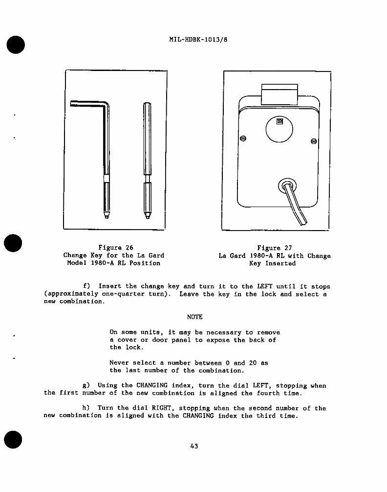
Ficure 26!ange Key ~or the La GardModel 1980-A RL Position
Figure 27La Gard 1980-A RL with Change
Key Inserted
f) Insert the change key and turn it to the L!Ill’until it stops(approximately one-quarter turn). Leave the key in the lock and select anew combination.
NOTE
On some units, it ❑ay he necessary to removea cover or door panel to expose the back ofthe lock.
Never select a number between O end 20 asthe last number of the combination.
g) Using the CHANGING index, turn the dial LEFT, stopping whenthe first number of the new combination is aligned the fourth time.
h) Turn the dial RIGHT, stopping when the second numbernew combination is aligned with the CHANGING index the third time.
43
of the

MIL-HDBK-1o13/8
i) Turn the dial IZPT, stopping when the third number of the newcombination is aligned with the CHANGING index the second time. Hold thedial fixed at this position.
j) Turn the change key to the RIGHT until it atops end remove thekey.
k) Work the new combination on the OPENING index at least threetimes with the door or container open. Record the new combination inaccordance with security directives. If the new combination fails tooperate, call a qualified locksmith.
3..4.1.5 Installation Procedure. To install the La Gard 1980-A RLcombination lock, proceed as follows (reference Figure 25):
a) Using template (provided with lock), position lock in desiredlocation.
b) Using template, drill errdtap four holes in the ❑ounting platefor the lock-mounting screws (1/4-20, item 4). Drill hole in mounting platefor the spindle sheft (0.625-inch (16-MM) diameter).
c) Install a dial ring assembly with the mounting screws provided,
d) Remove the combination lock Cover Screws (16) and Back Cover(14).
e) Lift off, BUT DO NOT DISCONNECT, the Lever Trigger (23) andTrigger Spring (24).
f) Remove tbe Drive Cam (11).
g) Carefully threed the dial spindle onto the drive cam untilsnug. DO NOT FORCE DIAL. Measure the excess spindle length, unscrew,remove, and carefully cut off the excese. Remove burrs.
h) Rethread the dial spindle onto the drive cam until snug andback off to the appropriate slot in the drive cam, either RH (right-hand),LH (left-hand), VO (vertical-up), or w (vertical-down).
To determine the “hand” of the lock: observe the back of the lock, If tbecombination lock bolt is pointing to the right, the correct spline positionof the drive cam is right-hand or “RH.” If the bolt points vertical-up, thedrive cam should be splined “VU,” etc.
i Insert the Spline Key (12) into the correct slot.
44
i-

MIL-HDBK-lo13/8
j) With the Back Cover (14) removed,Changing Index, and observe that the change keyaligned properly to accept tbe Change Key (15).
dial the combination on tbeboles in the wheels are
k) Reinstall the Lever Trigger (23) and Trigger Spring (24).
1) Install the Back Cover (14) and Cover Mounting Screws.
IMPORTANT
Reinstall the back cover before inserting thechange key, then follow the combination changingprocedure.
3.4. 1.6 Maintenance Recommendations. Periodic servicing will extend thelife of the lock and is essential for maintaining propar security. Eachtime the combination is changed, inspect the lock for wear, metal filings,drilled holes, cracks, or any other visual signs of attempts to defeat thelock by forced entry techniques. The inspection process should includeremoval of the back cover of tbe lock, and visual examination of each wheelpart as well as the cam and lever assembly to make sure nothing is worn ordamaged. If lubrication is required, use molybdenum-disulf ide (powder).NEVER use oil- or petroleum-based lubricants on combination locks.
Each time the back cover is removed, the combination should bereset. Remember to check the combination at least three times beforelocking the container.
Any maintenance other than changing tbe combination and inspectingthe lock should be referred to a qualified locksmith.
3.5 Moslar Mounted Combination Locks
3.5.1 MRK 120. The tlosler MRK 120 is a Group 1 combination lock. Ithas an index on the face of the lock which is used for both dialing andchanging tha combination. There ia no dial torque adjustment on this lock.Dial resistance is held within the allowable range (MIL-L-15596 Saries) bythe friction plug and spring. This lock is illustrated in Figures 28 and29.
.3.5.1.1 Opening Procedure. To open the Mosler MRK 120 Combination Lock,proceed as follows:
a) Turnthe combination is
b) Turnthe combination is
,0
the dial to the LEFT, stopping when the first numbar ofaligned with the index the fourth time.
the dial to the RIGHT, stopping when the second number ofaligned the third time.
45
II

MIL-HOBK-1013/8
I
Figure 28Front View, Mosler Model MRK 120 Mounted
Combination Lock
c) Turn the dial to the LEFT, stopping when the third number ofthe combination is aligned the second time.
d) Turn the dial to the RIGHT, pausing momentarily at zero, andcontinue turning until it stops. This retracts the locking bolt.
3.5. 1.2 Securing Procedure. To lock the MRK 120, turn the dial to theLEFT at least four complete revolutions.
3.5. 1.3 Combination Changing Procedure. To change the combination on theMRK 120, proceed as follows:
a)combination.directives.
Use the guidelines in paragraph 2.1.3e. to make up a newRecord the new combination in accordance with local security
46

●MIL-HoBK-lo13/8
●
●
‘--”N \ w
47
I

MIL-HDBK-lo13/8
b) Open the door or container as outlined in paragraph 3.5.1.1.
c) With the door or container open, throw the locking bolt(s) tothe locked position. If the unit has a bolt interlock, it will be necessaryto depress the interlock plunger before the bolt(s) can be thrown to alocked posit ion.
d) With the locking bolt in the locked position, turn the dial atleast four revolutions in one direction.
e) Add 10 to each number of the old combination. Proceed to openthe lock as directed in peragraph 3.5.1.1, steps a) through c). Do notexecute step d). For example, if the old combination is 20-71-31, adding 10will yield 30-81-41. The dial is stopped end held in place after the lastnumber, 41, is dialed.
If) Insert the change key into the keyhole in the back of the lock
(refer to Figures 30 and 31). The key is fully inserted when the bend inthe key reaches the cover plate. Turn the key in the direction indicated onthe back of the lock until it will not turn any farther. Do not force thekey.
NOTE
On some units, it may be necessary to remove a ocover or door panel to expose the back of thelock.
g) Add 10 tO each number of the new combination.I
h) Turn the diel LEFf’, stopping when the firet number of the newcombination plus 10 aligns with the index the fourth time.
i) Turn the dial RIGHT, stopping when the second namber plus 10aligns the third time.
j) Turn the dial LEFT, stOpping when the third number plus 10 isaligned the second time. Hold the dial in this position.
k) Turn the change key in the direction opposite to the arrow on.
the lock and remove th.akey.
1) Work the new combination at leaat three times with the door orcontainer open to verify that the combination is properly set and the lockis operating smoothly. If the new combination fails to operate, call for aqualified locksmith.
48

●
✌✌I
1“
III
I
I
,0
i.
1
MIL-HDBK-1013/8
1 I
Figure 30Change Key for the Mosler
Model MRK 120
Figure 31Mosler Model ilRK 120 Backplate
with Change Key in InsertedPOsition
3.5. 1.4 Installation Procedure. To install a Mosler MRK 120 CombinationLock, proceed as follows:
a) Using template (provided with lock), position lock in desiredlocation.
b) Using template, drill and tap four holes in the mounting platefor the lock-attaching screws (1/4-20) Drill hole in mounting plate forthe spindle shaft (O.625-inch (16-mm) diameter)
c) Make sure bolt is in the locked or engaged position hy pullingthe bolt out with fingers.
d) Remove back cover of the lock.
e) Securely fasten lock to mounting plate by installing the fourlock-attaching screws and tightening.
f) Fasten dial ring to door using screws and tighten tube nut (ifpresent on lock) and align with hole through door.
49

MIL-HDBK-lo13/8
g) Insert didl into dial ring and hold snug.
h) Carefully thread the dial spindle onto the drive cam untilsnug. DO NOT FORCE DIAL.
i) Measure thecarefully cut off excess,burrs.
excess spindle length, unscrew, remove, andleaving 1/16 inch (2 mm) above drive cam. Remove
I
j) Rethread the dial spindle onto the drive cam until snug andback off until the keyways in the spindle and drive cam line up.
k) Insert the spline key. Drive the spline key in carefully. Ifthe spline key becomes loose, the lock will not function properly. Makecertain that the spline key is tight.
1) Attach the back cover using the cover mounting screws Thelock is now ready to have the new combination set.
3.5. 1.5 Maintenance Recommendations. Periodic servicing will extend thelife of the lock and is essential for maintaining proper security. Eachtime the combination is changed, inspect the lock for wear, metal filings,drilled holes, cracks, or any other visual signs of attempts to defeat thelock by forced entry techniques. The inspection process should includeremoval of the back cover of the lock, and visua1 examination of each wheelpart as wel 1 as the cam and lever assembly to make sure nothing is worn ordamaged. If lubrication ia required, use molybdenum-d isulfide (powder) .NEVER use oil- or petroleum-based lubricants on combination locks.
I.’
●
Each time the back cover is removed, the combination shouldreset. Remember to check the combination at least three times beforelocking the contaj.ner.
be
Any maintenance other than changing the combination and inspectingthe lock should be referred to a quallfied locksmith,
3.5.2 MRK 302-402. The Mosler MRK 302-402 Groups 1 and IR combinationlocks have a unique manipulation-resistant cam mechanism. TWo audible im-pulses can be heard when the dial is turned past the zero area. The purposeof this feature is to defeat manipulation by the use of audio instrumentsWhen the MRK 302-402 was first introduced, the dial snd dial ring remainedthe same as the MR 302-402 Hand-Change lock (i.e. , one index on the face ofthe lock used for opening the lock and changing tha combination) , If yourMRK 302-402 has only one index, refer to paragraphs 3.2.1.1 and 3.2. 1.3 ofthis handbook for opening and combination changing procedures The morerecent MRK 302-402 has both an opening index and a changing index on theface of the lock. The difference between the FHfK 302 and the MRK 402 isthat the 302 has three wheels and a threa-number combination whereas the 402has four wheels and a four-number combination. llrere is no dial torque
50

1’
0
1-
MIL-HDBK-lo13/8
adjustment on these locks. Dial resistance is held within the allowablerange (MIL-L-15596F) by the friction plug and spring. The MRK 302-402 iSillustrated in Figures 32 and 33.
3.5.2.1 Opening Procedure. To open the Mos ler MRK 302-402 CombinationLock, proceed as follows:
a) Turn the dial to the LEIT, stopping when the first number ofthe combination is aligned with the OPENING index the fourth time.
b) Turn the dial to the RIGHT, stopping when the second number ofthe combination is aligned with the OPENING index the third time.
c) Turn the dial to the LEF1’, stopping when the third number ofthe combination is aligned with the OPENING index tbe second time.
CHANGINGINDEX 1 r OPENING
INDEX
Figure 32Front View, Moa ler Model NRK 302-402 Mounted
Combination Lock
51
I

MIL-HDBK-1013/8
o
0I
L52

I
I
o
.
I
I
MIL-ffOBK-1013/8
d) Turn the dial to the RIGHT, pausing momentarily at zero, andcontinue turning until it stops. This retracts the locking bolt.
3.5.2.2 Securing Procedure. To lock the MRK 302-402, turn the dial to theLSFT at least four complete revolutions.
3.5.2.3 Combination Changing Procedure. If there is both an opening andchenging index on the fete of the MRK 302-402, proceed with step a) tochenge the combination. If the lock has only an opening index, thecombination changing procedure is identicel to that of the Mos ler NRK 120.Use the procedure in paragraph 3.5.2.1, and 3.5.1.3, steps c) through k) .
a) Use the guidelines in paregreph 2.1.3e to ❑ake up e newcomhinat ion. Record the new combination in accordance with securitydirections.
b) Open the door or container as outlined in paragraph 3.5.2.1.
c) With the door or conteiner open, throw the locking bolt to thelocked position. If the unit has a bolt interlock, it will be necessary todepress the interlock plunger before tbe bolt can be thrown to a lockedposit ion.
d) With the locking bolt in the locked position, turn the dial atleest four revolutions in one direction.
e) With the present (old) combination, use the same procedure aswhen opening the unit except work the combination to the CHANGE indexinstead of tbe OPENING index. On reaching the last number, stop and holdthe dial in place.
f) Insert tbe change key (see Figure 34) into the change key holein the back cover. Turn the key in the direction indicated by the arrowuntil it stops. Leave the change key in this position (see Figure 35).
NOTS
On some units, it may be necessary to remove acover or door panel to expose the back of thelock
g) Turn the dial at leest four revolutions in one direction.This will erase the old combination.
h) With the new combination, turn the dial to the LEfT, stoppingwhen the first number aligns with the CHANGING index the fourth time.
i) Turn the dial to the RIGHT, stopping when the second number iseligned with the CHANGING index the third time.
:0 53

MIL-ROBK-lo13/8
j) Turn the dial to the LEFT, stoppingaligned with the CHANGING index the second time.this position.
k) Turn the change key in the oppositelock and remove the change key.
when the third number is o
Stop and hold the dial in
direction indicated on the
1) Work the new combination at least three times with the door orcontainer open to verify the combination is properly set and the lock isoperating smoothly. If the new combination fails to operate, callqualified locksmith.
3.5.2.4 Installation Procedure. To install a Mosler MRK 302-402Combination Lock, proceed as follows:
for a
a) Using template (provided with lock), position lock in desiredlocation.
b) Using template, drill and tap four holes in the mounting platefor the lock-attaching screws (1/4-20) Drill hole in mounting plate forthe spindle shaft (O.625-inch (16-mm) diameter).
Figure 34Change key for the Mosler
Model MRK 302-402
54
I
Figure 35Mosler MRK 302-402 Backplatewith Change Key in Inserted
Position

II
I
●
I
●
c) Make sure bolt isthe bolt out with fingers.
d) Remove back coves
MIL-KoBK-lo13/8
in the locked or engaged position by pulling
of the lock.
e) Securely fasten lock to mounting plate by installing the fourlock-attaching screws and tightening.
f) Fasten dial ring to door using screws and tighten tube nut (ifpresent on lock) and align with hole through door).
d
h)snug. Do not
i)carefully cutburrs.
_i)
Insert dial into dial ring and hold snug.
Carefully thread the dial spindle onto the drive cam untilforce dial.
Measure the excess spindle length, unscrew, remove, andoff excess, leaving 1/16 inch (2 mm) above drive cam. Remova
Rethread the dial spindle onto the drive cam until snug andback off until the keyw.sys in the spindle and drive cam lina up.
k) Insert the spline key. Drive the spline key in carefully. Ifthe spline key becomes loose, the lock will not function properly. Make
certain that the spline key is tight.
1) Attach the back cover using the cover mounting screws. Thelock is now ready to have the new combination set.
3.5.2.5 Maintenance Recommendations. Periodic servicing will extend thelife of the lock and is essential for maintaining proper security. Each
time tbe combination is changed, inspect the lock for wear, metal filings,
drilled holes, cracks, or any other visual signs of attempts to defeat thelock by forced entry techniques. The inspection process should include
removal of the back cover of the lock, and visual examination of each wheelpart as well as the cam and lever assembly to make sure nothing is worn ordamaged. If lubrication is required, use molybdenum-d isulfide (powder)
NEVSR use oil- or petroleum-based lubricants on combination locks.
Each time the back cover is removed, the combination should bereset. Remember to check the combination at least three times beforelocking the container.
Any other maintenance other than changing the combination andinspecting the lock should be referred to a qualified locksmith.
55
I

MIL-HLIBK-1013/8
Section 4: HAND-CHANGE LQCKS
.!!.1 General. Hand-change locks require disassembly before newcombinations cen be set. The whee 1s insida the lock have greduat ions from Oto 100 on their outer ring and a removable serrated-edge disk in the center.The position of the center disk determines the combination setting. Beforechanging tbe combination of any lock, read the antire change procedurecarefully. Read installation instructions thoroughly before beginning aninstallation procedure.
4.2 Mos ler Mount ed Combination Locks
4.2.1 MR 302-402. The Mosler MS 302-402 Groups 1 and lR combinationlocks have a unique manipulation-resistant cam mechanism. No audibleimpulses can be heard when the dial is turned past the O area. The purposeof this design feature is to defeat manipulation by the use of audioinstruments. The difference between the MR 302 and the Ml?402 is that the302 has three wheels and a three-number combination, whereas the 402 hasfour wheels and a four-number combination. There is no dial torqueadjustment on these locks. Dial resistance is held within the allowablerange (MIL-L-15596 Series) by tbe friction plug and spring. The MR 302 iaillustrated in Figures 36 and 37.
Figure 36Front View, Mosler Model MS 302-402 Mounted
Combination Lock
56
●
I
●
I

I
I
● 57
MIL-HilBK-lo13/8
—

tlIL-HOBK-1013/8
4.2, 1.1 Opening Procedure. To open the Mos lerLock, proceed as follows:
NR 302-402 Combination
a) Turn the dial LSFT, stopping when the first number of thecombination is aligned with the OPENING index the fourth time.
b) Turn the dial RIGHT, stopping when the second number isaligned with the OPENING index the third time.
c) Turn thewith the OPENING index
d) Turn tbecontinue turning until
dial LEFT, stopping when the third number is alignedthe second time.
dial RIGHT, pausing momentarily at O, and thenthe locking bolt is retracted.
4.2.1.2 SecurinE Procedure. To lock the NRleast four full revolutions.
4.2. 1.3 Combination Changinz Procedure. ToNR 302-402, proceed as follows:
302-402, turn the dial LSF1’at
change the combination on the
a) Select e new three-number sequence based on the rules inparagreph 2.1.3e. Record the new combination in accordance with securitydirectives.
b) With the old combination, open the lock as described ebove. ●c) With the door or drewer open, throw the bolt(s) to the closed
position. If the unit has a bolt interlock, it will be necessary to depressthis interlock plunger before the bolt(s) cen be thrown while the unit isopen. Use the procedure recommended by the unit’ s manufacturer.
d) ~row the locking bolt by turning the dial LSPT.
e) Remove the two back cover screws in the back of the lock.Remove the cover. This will expose the wheel pack.
NOTE
On some units, it may be necessery to remove apanel or small circular cover to expose the backof the lock.
CAUTION
Whenever disassembling the wheel pack in orderto change the combination, the components NUSTbe reassembled in the same sequence as they wereremoved from the wheel post.
58

I
●
✼✎
●
●
f)
8)sequentially
MIL-HOBK-1013/8
Remove the retsining ring from the wheel post.
Remove the wheels and spacers. The wheels are numberedon the outer plastic rinE (reference Figure 38). Wheel number
1 is set at-the first number of the c~mbf.nation and Is the uheel sdjacent tothe back cover plate.
h) Hold the number 1 wheel assembly with the numbers facing
upward and push the center disk up until it is removed from the outer ring.Rotate center disk until the setting index is aligned with the desirednumber on the ring (Figure 38). Press the center disk bsck into positionuntil it is flush with the outer plastic ring. Observe that numbersincresae counterclockwise on the wheels. Change the combination settings onthe remaining wheels in the same ❑anner.
i) Replace the parts on the post in the proper sequence. To help
identify wheels for proper reassembly, each Mos ler wheel has a number 1, 2,or 3 ❑olded next to one side of the gate (reference Figure 38). Furtherconf irmat ion is gained by observing that the gate (cutout) of the ❑iddlewheel (wheel No. 2) is 180 degrees opposite O. There ❑ay be ❑ore than onetension washer at the base of the wheel post. The numbered sides of the
wheels face upward. When the retaining ring is replaced, check to ensurethat it is properly seated in the groove on the post and that all wheels andspacers are properly ❑ounted on the wheel post.
j) After ❑aking sure that the dial is not set at zero, replacethe cover and screws. Tighten screws firmly.
k) Try the new combination at least three times with the door orcontainer open. If the new combination does not work properly, remove thewheel assembly and check tbe combination setting.
4.2.1.4 Installation Procedure. To install a Mos ler MR 302-402 Combination
Lock, proceed as follows:
a) Using template (provided withlocation.
b] Usin~ temDlate. drill and taD
lock), position lock in desired
four holaa in the mounting Dlatafor the lock-attacfiing ~crew~ (1/4-20). D~ill hole in mounting plate-firthe spindle shaft (O.625-inch (16-mm) diameter).
c) Make sure bolt is in the locked or engaged position by pullingthe bolt out with fingers.
d) Remove back cover of the lock.
e) Securely fasten lock to mounting plate by installing the fourlock-attaching screws and tightening.
59
I

I
I
I
I
I
I
L
IIIL-RDBK-1013/8
INN INNER
DIS DISK
R
INDEX NUMBER INDEX
Figure 38Mosler MR 302, Wheels
f) While aligning hole through door, fasten dial ring to doorusing screws,
g) Insert dial into dial ring and hold snug
h) Carefuly thread the dial spindle onto the drive cam untilsnug. DO NOT FORCE DIAL.
i) Maasure the excess spindle length, unscrew, remove, andcarefully cut off excess leaving 1/16 inch (2 mm) abova drive cam. Removeburrs.
j) Rethread the dial spindle onto tha drive cam until snug andback off until the keyways in the spindle and drive cam line up.
●
✌✎
●
60

MIL-lfDBK-1013/8
I
k) Insert the spline key. Drive the spline key in cerefully. Ifthe spline key becomes loose, the lock will not function properly. Makecertain that the splino key is tight.
1) Attach the back cover using the cover ❑ounting screws. Thelock is now ready to have the new combination set.
4.2. 1.5 Maintenance Recommendations. Periodic servicing wil 1 extend thelife of the lock and is essential for maintaining proper security. Each time
the combination is changed, inspect the lock for wear, ❑etal filings,drilled holes, cracks, or any other visual signs of attempts to defeat thelock by forced entry techniques. The inspection process should includeremoval of the back cover of the lock, and visual examination of each wheelpart as well as the cam and lever assembly to make sure nothing is worn ordamaged. If lubrication is required, use molybdenum-disul fide (powder).NEVER use oil- or petroleum-based lubricants on combination locks.
Each time the back cover is removed, the combination should bereset. Remember to check the combination at least three times beforelocking the container.
Any maintenance other than changing the combination and inspectingthe lock should be referred to a qualified locksmith.
‘o
,
I
I61

MIL-HDBK-lo13/8
THIS PAGE INTENTIONALLY LSFC BLANK
62
,

MIL-HDBK-1013/8
REFERENCES
NOTE: Unless otherwise specified in the text,users of this handbook should utilize the latestrevisions of the documents cited herein.
FEDERAL/MILITARY SPECIFICATIONS, STANDARDS, BULLETINS, HANDBOOKS, AND NAVFACGUIDE SPECIFICATIONS:
The following specifications and standards form a part of this document tothe extent specified herein. Unless otherwise indicated, copies areavailable from Commanding Officer, Naval Publications and Forms Center,ATTENTION: NPODS, 5801 Tabor Avenue, Philadelphia, PA 19120-5099.
SPECIFICATIONS
FED-SPEC FF-P-11O Padlock, Changeable Combination(Resistant to Opening By Manipulationand Surreptitious Attack)
STANDARDS
MIL-L-15596 Locks, Combination (Safe and SafeLocker)
NON-GOVERNMENTPUBLICATIONS:
The following publications form a part of thisspecified herein. Unless otherwise indicated,Underwriters Laboratories, 333 Pfingsten Road,
document to the extentcopies are available fromNorthbrook, Illinois 60062:
UL-768 Standard for Combination Locks
CUSTODIANNA~ - YD
PREPARING ACTIVITYNAVY - YD
PROJECT NO.FACR-0313
63
*LLSdXWERNMEfW twwwwomcu t9Mb704-034/30234
k