mil-b-67114a 26 october 1976 superseding piil...
TRANSCRIPT

MIL-B-67114A26 October 1976SUPERSEDINGPIIL-B-b711430 August 1977
MILITARY SPECIFICATION
BOLTS, RECESS DRIVE, GENERAL SPECIFICATION FOR
This specification is approved for use by allDepartments and Agencies of the Department of Defense.
1. SCOPE
1.1 w. This specification describes requirements for aerospace bolts(see 6.3) of ultimate tensile stress lbO-180 KSI and 180-200 KSI whose headscontain a recess for internal wrenching.
2. APPLICABLE DOCUMENTS
2*1 ~* The following documents of the issue in effect onthe date of invitation for bids or request for proposal, form a part of thisspecification to the extent specified herein.
SPECIFICATIONS
PPP+-1561 hardware (Fasteners and Heisted Items), Pachgfig and Pac~ngFor Shipment and Storage of
.
MIL-I-6866 Inspection, Penetrant, Method ofMIL-I-6568 Inspection Process, Magnetic ParticleMXL-H-6875 Heat Treatment of Steels (Aircraft Practice), Process forMIL-S-W79 Screw Threads, Controlled Radius Root with Increased Minor
Diameter, General Specification forMIL-F-b961 Fasteners, Externally Threaded, 450° F and 1200° F, Self Locking
Element forMIL-I-17214 Indicator, Permeability, Low-Mu (Go-No-Go)MIL-F-l&240 Fasteners, Externally Threaded, 2500F, Self Locking ElementMIL-H-81200 heat Treatment of Titanium and Titanium Alloys
tBeneficial comments (recommendations,additions, deletions) ad anYpertinent data which may be of use in improving this document shouldbe addressed to: ASD/ENESS, kright-1’attersonAFB, Oh 45433 W usingthe self-addressed Standardization Document improvement Proposal(DD Fo~ 1426) appearing at the end of this aocument or by letter.
for
F’sc5305FSC 530b
Downloaded from http://www.everyspec.com

MIL-b-67114A
STANDARDS
.hdeul
FED-sTD-ii2b Screw Thread Standards for Federal ServicesF’ED-STD-151 Metals, Test Methods
MIL-STD-105 Sampling Procedures and Tables for Inspection by AttributesMIL-STD-lj12 Fasteners, Test hethods
HANDBOUKS
MIL4’’mBK-5 Metallic Materials and Elements for Aerospace Vehicle Structures
(Copies of specifications, standards, drawings, and publications required bycontractors in connection with specific procur=ent f~ctions should be .obtained from the procuring activity or as directed by the contractingofficer.)
2.2 other 3~ ● The following documents form a part of thisspecification to the extent specified herein. Unless otherwise indicated, theissue in effect on the date of invitation for bids or request for proposalshall apply.
AMERICAN NATIONAL STANDARDS INSTITUTE
ANSI B4b.1 Surface Texture (Surface Roughness, Waviness, and Lay).
(Application for copies should be addressed to: American National StandardsInstitute, 1430 Broadway, New York, NY 100IU.)
AMERICAN SOCIETY FOR TESTIIUGAND MATERIALS
ASTM E-112 Est~ting Average Grain Size in MetalsASTM h-120 Chemical Analysis of Titanium and Titanium based Alloys,
Methods For
(Application for copies should oe addressed to: American Society for Testingand haterials, 1916 Race Street, Philadelphia, PA 19103.)
NATIONAL AEROSPACE STANDARDS COMMITTEE
NAS52t) Flushness Gage ana Stylus for 100° Countersunk Flush FastenerslUAs527 Inspection Procedure for Flush FastenerslUAs1347 Identification of Fasteners
(See supplement 1 for list of additional associated National AerospaceStandaras (NAS’S) for detail parts.)
(Application for copies should be addressed to: National StandardsAssociation, inc., 4527 Rugby flv, haShingLOn, DC 20014.)
2
Downloaded from http://www.everyspec.com

ML-B-57114A.
(Technical society and technical association specifications and standards aregenerally available for reference in libraries. They are also distributedamong technical groups and using Federal agencies.)
3. REQUIREMENTS
3*1 ~~ The individual item requirementsshall be as specified herein and in accordance with the applicable detailspecifications, hereafter called part standards. In the event of any conflictbetween requirements of this specification and the part standard, the lattershall govern.
3.2 ~.
3.2.1
4.3.1)
3*2*1*1 ~=
Chemical composition of the bolt materiti shall be inmateriaX specification listed on the part standard. (See
(Applicable to titanium alloy bolts only.) Hydrogencontent shall be not greater than .0125% (125 parts per million [ppmj). (See4.2.2.1 and 4.3.1.1)
3.2.2 ●
3.2.2.1 ~.
3.2.2.1.1 ~. There shall be no cracks in any location.defined as a clean, crystalline break passing through grain or(See 4.3.2)
A crack isgrain boundary.
3=2*2*1*2 JrwwJua. Inclusions are only permitted in recess surfaces andnonbearing surfaces of the head to a depth not “greaterthan .003 inch.Inclusions are particles of non-metallic impurities (such as oxides, sulphides,or silicates) which are in the metal during solidification. (See 4.3.3)
3.2.2.1.3 face . .m~ Laps, seams and similar surfaceirregularities are permitted as s;own on figure 1 and listed in table I. Lapsand seams are material discontinuities (folded metal) which do not cross grainboundaries. (See J+ .3.2)
3.2.2=2 ~.
3.2.2.2.1 ~ (Applicable to austenitic steels only.) The austeniticgrain size, as define; in ASTM E-112, shall be predominantly number 5 or finerwith grains as large as number 3 permissible. (See 4.3.3)
3=2.2.2.2 GAJLWW Grain flow in the threads shall be continuous and shallfollow the general thread contour as illustrated on figure 2. The maximumdensity of flow lines shall be at the bottm of the thread root radius. Grainflow in the heaa shall be continuous as illustrated on figure 3 but may showminor interruption resulting from finish machining operation. Grain flow linesshall not terminate in the head to shank fillet. (See 4.3.3]
. —*__
Downloaded from http://www.everyspec.com

MIL-B+711 4A
DIRECTION OF INSTALLATION
K SURFAGE IRREGULARITIES
1\
—MAJOR— -OIA
&NON-pRESSIJRE FLANK-
PER MISS19LE NOT PERMISSIBLE
FIGURE 1. .
None I
None~/‘Laps,seams,md otherirregulwities
seams
Folds, Se=ayor nicks
Overheating ~/Overheating #
, .TWLE I. Pe~issQle surface
.rrezltles .
ILocation Permissible Maximu depth normal to the surface (inches)
irregularityt 1
Shank dia. ●j12<shank
3.312 dia.&43ti
head to shankfillet . . .
ThreadRoot . . .Flank . .Crest . .
f.43b<shank shankdifi.875 dia>.b75
-. I -- I
.005 .010
HeadBearing .00b .010surface .Nonbearingsurface . .016 .020
.140 .140Pan head . .110 .110IOOo head
.005 .006 .008 .010Shank . . . Seam
and other surface irregd~ities are not permissible onthe
J/ Laps, se~s~presswe flank, on the nonpressure flank below the pitch diameter, or on the
nonpressme flank above the pitch diameteron two or more consecutive pitches.
They are permissible on the nonpressure flank above the pitch diameter.(See
---1---.005 I .006.010 .012.080 .Obo.060 .060
figure 1)-
ZI See 3.2.2.5.2
4
Downloaded from http://www.everyspec.com

MIL-B-d7114A
..
/
FXGURE 2. ~low in t- ●
I
I
FIGURE 3. ~ flow m he-. .
3.2.2.2.3 Jlefecta. Microstructure shall be free from bursts or voids. Alloysegregation which does not adversely affect mechanical properties isacceptable. For titanium alloys, microstructure shall aAso be free fraindications that it has been heated to a temperature above beta transus withoutsubsequently receiving significant mechanical reduction within the alpha-betatemperature range. (See 4.3.3)
3.2.2.3 ~ (Applicable to alloy steel bolts only.) Only thenonload bearing surfa;es of the head, the surfaces of the recess, and thechamfered end of the bolts (including the chamfered surface) may show signs ofcarburization, decarburization, or recarburization.withinthe limits specifiedin MIL-H-6b75. All other surfaces shall be free of these effects. Bolts areconsidered carburized, decarburized or recarbqrized if the difference inVickers.microhardness between the suspect area and the core of the bolt Isgreater than 45 points. (See 4.3.3 and 4.3.9.L)
3*2*2.4 ~. (Applicable only when listed on the partstandard.) Magnetic permeability shall be less than 2.00 (Air = 1.00) for afield strength H = 200 Oersteds. (See 4.3.4)
3*2*2*5 MmAumM&* Heat treatment shall be in accordance with thefollowing paragraphs or the part standard such that the mechanical propertiesof 3.2.3 are met.
3.2.2.5.1 .Qv .and c~rro~n re~t steel heat treatment shall be inaccordance with MIL-H-6b75. Alloy steel bolts”that are exempted from therequirements of 3.2.3.1 and 3.2.3.2 and the provisions of 4.2.1 shall have aRockwell C-scale hardness of 30-40 for 160-lbO WI bolts or 39-43 for 1~0-200KSI bolts. (See 4.3.9.1)
3.2.2.5.2 ~ heat treatment shall be in accordance withMzL-H-d12000 Slight overeating of the head is permissible providing thegreatest depth of overheating does not exceed the limits of table I whenmeasured normal to the top surface of the head. Structure of 6A1-4V alloyswhich has outlines of equiaxial prior all beta grains and no primary alpha 1S
considered overheated. (bee 4.j.3)
5
— -_—_—._——-—=
Downloaded from http://www.everyspec.com

MIL-B-87114A
3.2.3 Mechanical properties.
3.2.3.1 Tensile strength. (Not applicable to full thread bolts [see 6.3]with nominal length less than three times the nominal diameters or bolts with
w
grip length less than two times the nominal diameter.) Bolts shall have theminimum ultirmte tensile strength in accordance with table 11 and the partstandard. (See 3.2.2.5.1, 4.2.2.2, 4.3.5 and 4.3.9.1)
NominalDia
(inch)
0.1900.250
0.3120.3750.43800500
0.5620.6250.7500.8751.000
1.1251.250
TABLE II. Tension and shear values.
tinimum ultimate load (lbs)
I L6C)-180KSI Boltst
Thread I DoubleUNJF-3A Shear
.3125-24 14,600
.3750-24 21,000
.4375-20 28,600
.5000-20 37,300
.5625-i8 47,200
.6250.-18 58,300
.7500-16 83,900
.8750-14 114,0001.0000-12 149,000
1.1250-12 189,0001.2500-12 233,000
Tension
FlushTensionand PanHead ~/
3,1805 ,82(.)
9,20014,00018,90025,600
32,40041,00059,50081,500106,000
137,000171,000
FlushReducedHead ~/
2,0003,700
5,0007,2009,00013,500
17,00021,00030,70042,00055,000
1/ Based on MIL-HDBK-5 shear stress areas.~/ Based on FED-STD+28 tensile stress areas.~/ Based on head strength.
3.2.3.2 Shear strength. (Not applicable to full
180-200 KSI Bolts IDoubleShear~1
Tension I
FlushTensionand PanHead ~/
6,120 3,60010,600 6,500
16,500 10,40023,800 15,80032,400 21,30042,400 28,700
53,600 36,50066,200 46,00095,400 63,200130,000 86,300170,000 112,000
214,000 144,UO0266,000 180,000
FlushReducedHead ~/
2,1303,930
I 5,6708,13010,50015,000
18,80023,30033,800
thread bolts.) Bolts shallhave the minimum ultimate shear strength in accordance with table II and thepart standard. (See 3.2.2.5.1, 4.2.2.2, 4.3.6 and 4.3.9.1)
3.2.3.3 Tensile fatigue life. (Not applicable to bolts with full threads,drilled heads, drilled shanks, or grip length less than three times the notinalshank diameter.) The bolt shall be capable of sustaining the high tensilefatigue load specified (percentage of the minimum ultimate tensile strength) onthe part standard and the low tensile fatigue load of ten percent of the highload applied alternately for Lhe average number of cycles specified below and aminimum of 45,UW cycles. The first sample lot is acceptable if the average
-
b
- .
Downloaded from http://www.everyspec.com

MIL-B-87114A
life is greater than 100,000 cycles; the lot is rejectable if the average lifeis less than 65,000 cycles. The combined first and second sample lot (requiredif the first sample lot is neither accepted nor rejected) is acceptable if theaverage life is greater than 60,000 cycles; the lot is rejectable if theaverage life is less than 65,000 cycles. The combined first, second, and thirdsample lot (required if the combined first and second sample lot is neitheraccepted nor rejected) is acceptable if the average life is greater than b5,000cycles. (See 4.2.2.3 and 4.3.?)
3.2.3.4 Stress du@W&y.
. (Applicable only when listed on the partstandard.) Bolts shall sustain a load of 75 percent of the minimum ultimatetensile strength for a minimum of 23 hours. (See 4.3.8)
392*3*5 ~. Hith a 20*0.5 pounds-force (lbf) axial load, therecess shall be capable of transmitting the torque loads specified in table 111in both the installation antiremoval directions (one cycle) and then meetingthe requirements of 3.3.1 and 3.3.1.2. (See 4.3.10)
3.3 ~ Bolt configuration shall be in accordance with thefollowing parsgrap~s and the part standard. (See 4.3.11)
3.3.1 ~. The bolt head shall have forh and dimensions in accordance withthe.part standard and as determined using table III. (See 4.3.11 and 4.3.11.1)
3.3.1.1 ~o-. The boit head shall be formed by forging. The recess may beforged or machined. (See 4.3.3)
3.3.1.2 &gce~. Configuration of the recess shall be in accordance with thepart standard. (See 4.3.11.2)
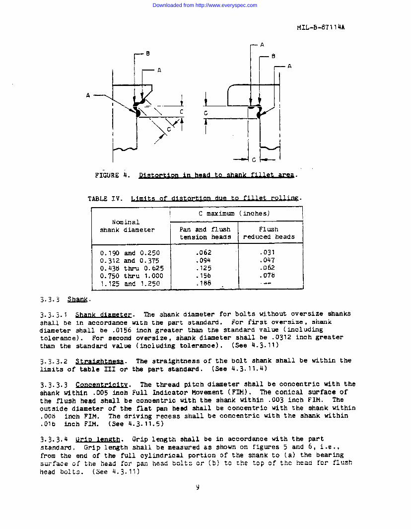
3.3.2 ~. Unless otherwise specified on the part standard, the junctureof the bolt head and the shank shall be cold worked by a rolling process afterthe completion of all machining, grinding and thermal treatments. The filletmay be distorted a maximum of .002 inch above or below the basic contour. Thisdistortion, shown as the shaded areas A and B on figure 4, shall be within thelimits given in table IV. A short tapered lead into the fillet area ispermissible providing the dimensions are within the limits of table IV. Filletradius shall be in accordance with the part standard. (See 4.3.3, 4.3.11, and4.3.11.3)
7
Downloaded from http://www.everyspec.com

—. .
MIL-BA711 4A
.—. - --
A
-.Flush tension head
/ /.“
/
r !=‘——————7. loOWO
““\L-
) V IIpm head Flush reduced head
0.190
0.250
0.312
0.375
0.438.
0.500
0.562
0.625
0.750
0.875
1.000
1.125
1.250
.0300
.0275
●0360.0330
.0410
.0375
.0460
.0420
.0465
.0425
.0535
.0490
.0590
.(HO
.0660
.0610
.0760
.0700
.0855,0785
.0955●0890
.1600
.1515
.1810
.1715
.3147
.3145
.4245
.4243
.5389
.5387
.6532
.6530
.7784
.7782
.8902
.8900
1.W281.0026
1.11241.1122
1.34401.3438
1.57321.5730
1.8o261.&)24
1.92141.9212
2.12662.1284
.0030
.0030
.0030
.0025
.0025
.0020
.0020
.0020
.0020
.0020
.0020
●Oo20
.0020
50
125
100° Fle tens= and m had bolt100° Flushreduoadhed bolt
Recess
CL C&e &G&e Wwai@- ~
stz’aight-
Dia tom= Prottiy ness torqueMa) protmslon
(inOh) (MChe9 (lbf-m) (i% (inches (lbf-in)(inOh)
1/ p’ inch)per inch)
“/I 1
2’50
430
925
1250
1650
2400
I
.
.0220
.0195
.0255
.0225
.0295
.0260
.0320
.0285
.0415
.0375
.0425
.031m
.0490
.0440
.0515
.0460
.0550●0490
.0890
.0820
.0980
.0915
.2441
.2439
.3315
.3313
.4047
.4045
.4854
.4852
.5697
.5695
.6499
.6497
.7200
.7198
.8011
.8009
.9702
.9700
1.11241.1122
1.28961.2894
.0030
.0030
.0030
.0025
.0025
.0020
●0020
.0020
.0020
.0020
.0020
35
50
125
250
430
750
1100
1WC)
IL
1
li Notapplicabletopanhead bolts
b
Downloaded from http://www.everyspec.com
MIL-B-87114A
B
h A
A%/!~ u\ \ c\ “+_ >
ct
I AMGFIGURE 4.
TABLE IV. ts due to f~et .of rol~ ●
C maximum(inches)Nomtial
shank diameter Pan and flush F1ushtension heads reduced heads
0.190 and 0.250 .062 .0310.312 and 0.375 .094 .0470.438 thru 0.625 .125 . .0620.750 thru 1.000 ● 156 .o7b1.125 and 1.250 .186 - .--
3=3=3=1 ~. The shank diameter for bolts without oversize shanksshall be in accordance with the part standard. For first oversize, shankdiameter shall be .0156 inch greater than the standard value (includingtolerance). For second oversize, shank diameter shall be .0312 inch greaterthan the standard value (including tolerance). (See 4.j.11)
3=3-3.2 ~. The straightness of the bolt shank shall be within thelimits of table HZ or the part standard. (See 4.3.11.4)
3*3*3*3 @2MZW&W* The thread pitch diameter shall be concentric with theshank within .005 inch Full Indicator Movement (F~). me conical !Wface ofthe flush head shall be concentric with the shank within .003 inch FIN. Theoutside diameter of the flat pan head shall be concentric with the shank within.008 inch FIM. The driving recess shall be concentric with the shank within.Olb inch FIM. (See 4.3.11.5)
3.3.3.4 ~ 1- ● Grip length shall be in accordance with the partstandard. Grip length shall be measured as shown on f’igures5 and 6, i.e.,from the end of the full cylindrical portion of the shank to (a) the Dearingsurface of the head for pan head bolts or (b) to the top of the head for flushhead bolts. (See 4.3.11)
Y
Downloaded from http://www.everyspec.com

MIL-B-87114A
FIGURE-5.
-G=%f#&wq r--~+_yi&””” -OF SWiK)
, ~ =“ -1 r %sH.’lkw-,
I
Lst u) o n i mRu D CHA?fFERR1.mou’r
IIW’ERIAL~ -
F~G~E G. ~0
3.3,4 ~ea~. Thread form and dimensions shall be in accordance withMIL-S-8B79, UNJF series and the Part standard●
(See 4.3.11.6)
3.3.4.1 j’or~. Threads shall be fully formed after final heat treatment bya rolling process or as noted in the part standard. (See 4.3.3 and 4.3.11.6)
3.3.4.2 ~. Thread lead and runout shall be in accordancewith MIL-S-5b79. Xncunplete thread pitohes are permissible at the chamfer~end of the bolt and at the juncture of the unthreaded portion of the shank asshown on figure b. The incaplete lead thread shall be not less than one-halfpitch wide and the incomplete lead thread plus chamfer shall be not more thantwo pitches wide. The incomplete thread next to the shank shall include athread runout not less than one pitch wide nor more than: (a) two pitches widefor standard shank; (b) two pitches plus 0.0167 inch wide for first oversize;or (c) two pitches plus 0.0334 inch wide for second oversizeo For other thanfull thread bolts, the runout shall terminate not less than one-quarter pitchfrom the grip dimension. For full thread bolts, the runout shall terminate atthe end of the full cylindrical portion of the shank, but not extend into thefillet. Thread runout shall blend smoothly into the shank diameter so as toeliminate any abrupt change n cross-sectional area. [Note: Figure 6 shows astandard shank.] (See 4.3.11 and 4.?.11.b)
10
-
I ., I -
Downloaded from http://www.everyspec.com
MIL-B-87114A
3.3.4.3 ~1- Thread length shall be in accordance with the partstandard. (See 4.3.llj
3.3.5 ~ elm When self locking element is required, it shallbe in accordance with MIL-F~18240 or MIL-F-8961 and the part standard. (See4.3.12)
3.4.1 face te~ e. Surface texture of the bearing surface of the head,head to shank f’illetradius, shank, and threads shall be not greater than 32Roughness Height Rating (RHR). Surface texture of all other surfaces shall benot greater than 125 RHR. (See 4.3.13)
3.4.2 ~= Surface treatment shail be in accordance with thepart standard. (See 4.3.14)
3*5 ~. Bolt identification shall be in accordance with NAS1347 type IVor the part standard. (See 4.3.11)
4. QUALITY ASSURANCE PROVISIONS
4.1 lle~DonslblQt~ fo. . . r insnection. Unless otherwise specified in the
contract, the contractor is responsible for the performance of all inspectionrequirements as specified herein. Except as otherwise specified in thecontract, the contractor may use his own or any other facilities suitable forthe performance of the inspection requirements specified herein, unlessdisapproved by the Government. The Government reserves the right to performany of’the inspections set forth in the specification where such inspectionsare deemed necessary to assure supplies and services conform to prescribedrequirements.
4.2 tv .ectzo~ Quality confom=ce inspections shall beas specified in table V to verify t~at the requirements of Section 3 are met.
4.2.1 .ectlon lo~. Inspection lot shall consist of parts of the samediameter, head and recess styles, fabricated from the same mill heat ofmaterial, heat treated and finished in one continuous run, and submitted forinspection at the same time. Each inspection lot shall be identified by acontrol number. For the purpose of reducing the number of samples used fordestructive tests, it will be permissible to consider two or more sub-lots ofbolts of the same diameter and head style (but different length) and made fromthe same heat of material as one lot. In such cases, the n~ber of specimensfor destructive test shall be based on the combined totals of the sub-lots.Test specimens shaLl be selected from each sub-lot on a proportional basis andeach sub-lot shall be represented by at least one part except where parts aretoo short for mechanical tests, then these tests shall apply to sub-lots oflonger parts.
Downloaded from http://www.everyspec.com

MIL-B-87114A
Requirements Test meth~Inspection
paragraph paragraph
Composition 3.2.1
Hydrogen 3.2.1.1
Discontinuities 3.2.2.1.1, 3.2.2.1.3
Macro and Micro examtiations 3.2.2.1.2, 3.2.2020193.2.2.2.2, 3.2.2.2.3, 3.2.2.33.3.1.1, 3.3=2? 3=3”4”1
Magnetic permeability
Heat treatment
Tensile strength
Shear strength
Tensile fatigue life
Stress durability
Recess strength
Configuration
Head height
Recess dimensions
Fillet
Shank straightness
Concentricity
~eaa to shank
Thread to shank
Drive recess to shank
Thread examinations
Self locking element
Surface texture
Surface treatment
3.2.2.4
3.2.2.5
3.2.3.1
3.2.3.2
3.2.5.3
3.2.W
3.2.3.5
3.3, 3.3.1, 3.3.2, 3.3.3.1,3.3.3.4, 3.3.4.2, 3.394.3, 3.>
.3.3.1
4.3.1
4.3.1.1
4.3.2
4.3.3, 4.3.9.2
4.3.4
4.3.3, 4.3.9.1
4.3.5, 4.3.9*1
4.3.6, 4.3.9*1
4.3.7
4.3.8
4.3.10
4.3.11c
3$3.1.2
j.3.2
3.3.3.2
3.3.3.3
j,j.s.j
3.3.3.3
3.3.3.3
3.3.4, j.3.Qol,
3.3.5
3.4.1
3.j.4.2
4.3.11.1
4.s.11.2
4.3.11.3
4.3.11.4
4.3.11.5
4.3.11.5.1
4.s.11.5oz
4.3.71.5.3
4,3.11.6
4e~,Jz
4.3.13
4.3.14-
12
Downloaded from http://www.everyspec.com

MIL-B-87114A
4.2.2 ~. Sampling shall be in accordance with MIL-STD-105 except forhydrogen, tensile, shear, and fatigue testing. Samples for inspection shall beselected at random except as noted under table VI. The same sample may be used
for inspection of configuration, thread dimensions, surface texture, andmarking. If this sample passes these inspections, the sample for destructivetests may be selected at random from this group. The sample used for tensile
test may also be used for shear test, provided there is at least threediameters of undamaged and unthreaded shank availaDle for the shear test. Aseparate sample is necessary for metallurgical examination.
TABLE VI. ●
Test method parsgraph
4.3.2, 4.3.11.3, 4.3.11.6 .
4.3.11.4, 4.3.11.5
All other except 4.3.1.1,4.3.5, 4.3.6, 4.3.7
Level I AQL I
II 0.65
11 1 . 0
s-2 2.5
Note: Any sample showing indications of cracks or surface irregularities whentested in accordance with 4.3.2 shall also be microexamined to confirm thepresence of those defects. Any sample showing hdications of carburization,decarburization, or recarburization when examined in accordance with 4.3.3shall also have a microhardness test to confirm the presence of those defects.
4.z.z.I ~b Sampling shall be one bolt per lot selected atrandom. If the hydrogen content is greater than specified, two additionalbolts per lot shall be tested.
4.2.2.2 le . for t- .s~ and Sample size for firstand second sample shall be as listed in table VII. A &corIcIsample is requiredwhen the lot is neither accepted nor rejected on the first sample; that is,X1-KaSl<M and X1-KrSl~M. (See 3.2.3.1, 3.2.3.2 ad 6.3)
TABLE VII. VarQQle .
I Lot size
Less than 201201 thru 5005 0 1 t h r u l ~ o o1301 thru 32003201 thru 8000Greater than 8000
N1 Ka Kr Seoond sample size Nt Kt
5 2.21 0.89 10 15 1.746 2.22 0.94 12 18 1.707 2.32 1.10 14 21 1.788 2.48 0.99 16 24 1.5110 2.34 1.31 20 30 I.bo15 2.20 1.42 30 45 1.83
4.2.2.3 ~ibute~ for fa~e tea Sample size for first, second,and third samples shall be as listed in table*VII1. A second sample isrequired if the lot is not accepted or rejected on testing of first sample, anda third sample is required if the lot is not accepted or rejected on thecombined first and second sample. (See 3.2.3*3)
13
Downloaded from http://www.everyspec.com

MIL-B-b7114Af-e.
TABU VIXI. ~ ~ fort- ●
Sample no. Sample size Total,Lot size
Less t- sol
3 0 1 t h r u 5 0 0
501 tm 1300
1301 thru 3200
3201 thru 8000
Greater than 5000
FirstSecondThird
FirstSecondThird
FirstSecondThird
FirstSecondThird
FirstSecondThird
FirstSecondThird
325
437
549
6511
7512
b614
35
1 0
4
714
59lb
61122
71224
b1428
I
4 . 2 . 3 Mu 2 a = = = ” The manufactwer shall mai.ntatia record of theThe record shall be
results of all tests required by this specification. ,available to the procuring activity and to gover~ent inspectors
in the
Derfor’manceof their duty. Unless otherwise s~eclfled, these records shall be.maintained for seven years.
of ex~nat~.
4.3.
4.3.1. ,
Osltlcul. Samples shall be tested for chemical composition inAnalysis. If results
accordance with ~’EOsTD-151 Method 112”1~ ‘pe~tr~h~~i~cdahdysi~ ,of test are doubtful, FEDSTD-151 Method 111. ,
shall be
used. A certification of compliance, including mill test report, may be
accepted in lieu of this test as evidence that the materialcomplies with its
-specificationrequir=ents.
4 . 3 . 1 . 1 tivdro~ Samples shall have lubricmt, if any, removed.Material
.sufficient for analysis shall be removed from themfillet.
Analysis shall be by
the vacuum fusion method in accordance with ASTM b-120.Equipment shall be
capable of analyzing hydrogen to .0010$ (10 ppm).Reject the lot if one or
more bolts of the second sample has hydrWen(See 3.2.1.1)
content greater than specified.
.
4.3.2 us~on~- Samples shall be examtiea using magnetic partxcle
inspmtion in accordance with MIL-I-68btior fluorescent penetrmt inspection in
accordance with MIL-I-686b as appropriate.hagnetic or penetrmt indications
of themselves shall not be cause for rejection.Samples showing indications of
discontinuities shall be microscopically exatied (see 4.3.3).-
1 4
Downloaded from http://www.everyspec.com

MIL-B-87114A
4 . 3 . 3.cro e~ Samples other than those to be examined for
cracks or surface irregularities s~all be sectioned as shown on figue 74 Thesections shall be etched with an etchant appropriate to the material and theexamination to be performed. Specimens shall be examined at a magnificationnot less than the values in table XX.
DIA
I I II ----3 D
[I- NOM OtA---v e
T
TABLE IX. ~tion for maG,uu@ micro exmim!am. ●
t
Property Magnification
Cracks (See 4. 3 . 2 ) 6XSurface irregularities (See 4.3.2) 6XInclusions 6XGrain flow in head 6XMicrostructural defects 25xF i l l e t ~ ~ ~
Carburization, decarburization,and reoarburization (See 4.3.9.2) 5 0 X
Overheating (See 3 . 2 . 2 . 5 . 2 ) 5 0 XGrain size and type 5 0 XGrain flow in thread 5 0 X
4.3.4 Magnetic permeability shall be tested usingindicator meeting the requir&ents of MIL-I-17214.
4 . 3 . 5 ~enstie stz Ultimate tensile strength shall be tested inaccordance with MIL-STD~1312 Test b, Tensile Strength. hhen specified by theprocuring activity, MIL-STD-1312 Test 18, Elevated Temperature TensileStrength, shall also be performed.
4 * 3 * ~ MMLmXm a * Ultimate shear strength shall be tested in accordancewith MIL-STD-1312 Test 13, Double Shear. khen grip length is too short forTest 13, use either MXL-STD-1312 Test 20, Single Shear, on the bolt or Test 13on a specimen of the bolt material processed with the production lot.
4 . 3 . 7 ~ . Tension fatigue life shall be tested in accordance withMIL-STD-1312 Test 11, Tension Fatigue. If the item does not fail by 130,000cycles, the value used for the average shall be 130,000 cycles.
4.3.8 Stress dur~. Stress durability shall be tested in accordance with
MIL-STD-1312 Test 5, Str&s Durability, for a minimum of 23 hours. Samplescompleting Test 5 shall be examined using magnetic particle inspection perMIL-I-bb68 or fluorescent penetrant inspection per MIL-I-obob as appropriate.
1 5
Downloaded from http://www.everyspec.com
MIL-B-d7114A
4.3.9 ~. Samples requiring a hardness test shall be prepared inaccordance with MIL-STD-131Z Test 6, Hardness.
4*3*9*1 ~* A hardness test in accordance with MIL-STD-1312 Test 6shall be performed. Bolts are rejectable if the hardness reading is not withinthe range specified in 3.2.2.s or on the part standard.
4.3*9*2 ~= If the sample shows indications of carburization,clecarburization,or recarburization, a microhardness test in accordance withMIL-STD-131Z Test 6 shall be performed. Reading shall be taken in threelocations in the suspect area and three locations in the center of the bolt.Bolts are rejectable if the difference in Vickers microhardness is greater thanspecified in 3.2.2.3.
4.3.10 ~ strg. The recess shall be torque tested in bothinstallation and removal directions using a driver bit meeting the requirementsof the applicable driver bit specification. Axial end load shall be not lessthan 19.5 lbf and not greater than 20.5 lbf. Axis of the driver shall bealigned within 3° of the centerline of the bolt.
4.3.11 ~o~ . Visual and dimensional examinations shall be performedby the inspector using conventional measuring equipment (micrometer, calipers,etc.) and additional equipment as specified in the following paragraphs.
4.3.11.1 jjea~loq ● (Applicable to 100° flush head bolts only.)height of the 100° flush head shall be examined in accordance with NAS527 usingthe gage specified in NASS24 ana the gage hole diameters listed in table III.
4.3.11.2 @SS d~ . The recess configuration shall be measured toaetermtie acceptability in accordance with 3.3.1.2. n g~e applicable to therecess style shall be used to measure those recess dimensions for which thegage was designed. .
4.3.11.3 Fillet. The distortion due to fillet rolling shall be measured usingan optical comparator with a magnification not less than 25X.
4.3. 11.4(maximumpoint ofinch.
4 . 3 . 1 1 . 5
. Support each end of the shank in V blockswidth of each block 0.250 inch). Rotate the shank and measure thegreatest deviation with a dial indicator graduated in 0.001 of an
.
4 . 3 . 1 1 . 5 . 1 ~tow Support &he shank in a V block or flat elementtri-roll gage. The head ~o shank juncture shall be 1 . 0 to 1.5 times the shankdiameter from the face of the block or rolls. Using a dial indicator touchingthe midsection of the conical surface of the 100° flush head or the peripheryof the pan head, rotate the shank.
4.3.11.5.2 wad to Support the thread on a tri-roll screw threadcanparator with funtional g&ing elements (“~o” profile). Using a dialindicator touching the shank 1.0 to 1.5 times the shank diameter from thethread, rotate the thread. For bolts with grip length less than the sh~kdiameter, center the indicator on the unthreaded portion of the shank.
16
—_=_ _____ _—.—= .
--
———__ —.
Downloaded from http://www.everyspec.com
4 * 3 * 1 ~ * 5 * 3 ~ ~ S u p p o r t ‘ h e s h ~ n k i n a vdial indicator touching the bottom of the recess, rotate the
4.3.11.6 .e~ ● Threads shall be examined inP!IL+-8879 Method B.
MIL-B-87114A
block. Using ashank.
accordance with
4.3.12 Self lo@@g elm Sample shall be tested in accordance withMIL-F-15240 or MXL-F-851blas”applicable.
4 . 3 * 1 3 wc mLm@M* Surface texture shall be tested in accordance withANSI B46.1 by visual or fingernail comparison with standard surface texturespecimens● lf results are doubtful, a profilometer shall be used if surface isaccessible.
4 * 3 . J 4 ~ * Thickness of the surface treatment of plated orcoated bolts shall be determined in accordance with MIL-STD-1312 Test 12,Thickness of Metallic Coatings. When specified by the proaurring activity,MIL-STD-1312 Test 1, Salt Spray, shall also be perfonmd.
5. PACKAGING
!j.1 ~. The items shall be packaged, packed, and marked Level A, B,or C as specified (see 6.2) in accordance with PPP-H-1S81.
6. NOTES
ti.1 ~ e d U . The bolts are intended for the assembly, repair, andmaintenance of the structure of weapon systems (including aircraft andmissiles) and supporting equipment.
6.2 W ki m u W a . Procurement documents shall specify:
a. Title, number and date of this specification
0. Part number of the bolt desired (see part standard)
c$ Quantity
d . Applicable levels of pacldng (see 5.1)
e. Additional tests required (see 4 . 3 . 5 and 4.3.14)
f. Government inspection and acceptance at the source of manufacture fordirect government procurements.
6“ Inspection and acceptance at the source of manufacture or at the receivingpoint for nongovernment procured items intended for government applications.
0 . 3 . 1 jjol~. A headed, externally threaded fastener for installation into aninternally threaded mating part used to clamp two or more pieces together.This includes items of Federal Supply Clas~ificatiorm (FSCSJ 5305 md 5306.
6.3.2 ~ Thread extends to head-to-shank fillet. Also known as“threaded to the h~ad” and “fully threaded”.
Downloaded from http://www.everyspec.com

r~L-b-d7114A
b.5~3 ~. A military, industry, or aerospace company specificationcontrol arawing ot’a fastener approvea for use in equipment for the Department01”Derense.
b
b.~.4 ~eces~. m internal wrenching element, usually manufactured in theheads of bolts and screws, through which torque is appliea by use of a driver.
b.3.5 J’41
6.3.6 ~
0..3.7 ~lot
( ) . 3 . 9 K Jsample lot
6 . 3 . 1 0 &strength in
b.~.11 11
Number o!’ items in first sample lot
Number of items in combined (i.e., first and seoonci)sample lot
Coefficient of S1 used to determine acceptance of the first sample
Coefficient of S1 used to cletermine if second sample is required
Coefficient of ~ used to determine acceptance of the combined
Minimum ultimate tensile strength or minimum ultimate snearaccordance with table 11
Aver?uze of inaiviaual tensile or shear strength values or the— —I’irst sa%le 10C
O.j.lz xf. Average of inaiviaual tensile or snear stengtn values of tnecomoinea=ample lot
values
0.3.15values
h . 3 . l bvalues
b.j.lT
b.j.~b
bum of the squares of’the inaiviaualiirst sample lot
Sum of tne squares of tne inaiviaualcombined sample lotm
tensile or snear strength
tensile or shear strengtn
( w)< Square of the sum of individual tensile or shear strengtho-1’irst ‘sampie lot
.2( Xht) Square of the sum of individual tensile or shear strength
o~combint?d sample lot
S 1
S t v
Itj
.— —= ——=. . . . . . -—=——--=—.=—.==-—— ____ ___—
Downloaded from http://www.everyspec.com

MIL-B-87114A
6.4 ~“ Asterisks are not used in this revision toidentify changes with respect to the previous issue, due to the extensivenessof the changes.
6 . 5 ter~ agreement Certain provisions (3*3.1.2! 3~3.4~ andtable 111) of this specification are the subject of internationalstandardization agreements (STANAG 3394, ASCC AIR STD 17/24, ASCC AXRSTD 17/30, and ASCC AIR STD 17/40). When amendment, revision, or cancellationof this specification is proposed which will violate the internationalagreements concerned, the preparing activity will take appropriatereconciliation “actionthrough international.standardization channels?including departmental standardizationoffices, if required.
Custodians:Army - AVNavy - ASAir Force - 11
Review activities:Army - MI, MAir Force - 99DLA - IS
1 9
Preparing activity:Air Force - 11
Project 53GP-0090
Downloaded from http://www.everyspec.com
,
mm
ASDIENESSWright-Patterson APB, O 45433
POSTACiE ANO FEES PAIDDEPARTMENT OF AIR FORCE
Do&318
OFFICIAL MJ81NESS●ENALTY FOR PRIVATE USC $300
ASD/ENESSWright-Patterson AFB, O 45433
FOLD
———=-—————-—.—-—=-- -————— . . . . . . —. . —
Downloaded from http://www.everyspec.com

,(
i STANDARDIZATION DOCUMENT !MPRCVEMENT PROPOSAL
I1N6TRUCTIOPU3:T%isforminprovided to adicit beneficial commonta which may improve this document ●d●nhance its use. DoD contractors, govemm.nt ●ctivities, manufacturers, vendors, or otherprospectiveusersofthedocument are Invited to submit comrnen~ to the ~overnment.FoIdonlinesonrevenwside, staple in corner,and amd to preparingsctimty.Attach any pertinent data which may be of use in improving this document. If
; there ●re additional paperat attach to form and place both in an envelope addressed to preparing activity.A1 response will be provided to the submitter, when name and address is Drotided. within 30 days indi=ting tit
the 1426 was re&ived and when any ●ppropriate action on itwill be &mpleted.NOTE: This form shallnotbeusedtomubmit~uestsfor waivers, deviations or clarification of specificationrequirements on current contracx. Commenw submitted on this form do not constitute or impiy authorizationto waive any portion of the referenced documents) or to amend contractualrequkemen-.
NAME OF ORGANIZATION ANO ADORESS OF SUBMITTER
.. .
,0 VENDOR ~ uSER ~ MANUFACTURER
1. n HAS ANY PART OF THE C)OcuMENT CREATED PROBLEMS OR REQUIRED INTERPRETATION IN PROCUREMENT
uSE? .0 IS ANY PART OF IT TOO RIGID, RESTR~CTIVE, LOOSE OR AMSIGUOUS7 PLEASE EXPLAIN BELOW.
A. GIVE PARAGRAPH NUMBER AND WORDING
8. RECOMMENCED WOROING CHANGE
C. REASON FOR RECOMMENOEO CHANGE{SI
~UBM ITTE D SV (Mnted or typedname and mtdMu - ~JPtl~n~t) ]TELEF~ONE NO.
1 d
ml ‘“”M1426PREVIOUS EDITION WILL BE USED.1 ocT 76
—---- - ———.-
Downloaded from http://www.everyspec.com