mikrokopter pilot operating manual
TRANSCRIPT

1
Mikrokopter Pilots Operating Manual Dennis O'Hara
http://northernimages.com Northern Images Photography
5431 Shady Lane Duluth, MN 55811
Phone: +1 218-729-5590 email- [email protected]
Copyright © Dennis O’Hara All Rights Reserved
Mikrokopter Pilots Flight Guide ............................................................................................................................... 1 Section 1 -‐ Introduction/Forward ............................................................................................................................ 6 Warnings, Cautions, Notes ..................................................................................................................................................................................... 6 Contact ............................................................................................................................................................................................................................ 7 Revisions History ....................................................................................................................................................................................................... 7 Section 2 -‐ MK -‐ Overview ............................................................................................................................................ 8 Frame .............................................................................................................................................................................................................................. 9 Propellers ................................................................................................................................................................................................................... 10 Electric ......................................................................................................................................................................................................................... 12 Batteries ...................................................................................................................................................................................................................... 13 General Power Wiring .......................................................................................................................................................................................... 14 Motors .......................................................................................................................................................................................................................... 16 Electronics ................................................................................................................................................................................................................. 18 Flight Control ............................................................................................................................................................................................................ 18 Overview ........................................................................................................................................................................................... 18 Terms ................................................................................................................................................................................................. 20 Sensor Description ........................................................................................................................................................................ 20 Gyroscopes (Gyros) ................................................................................................................................................................................................ 21 Acceleration Sensor (Accelerometer-‐ACC) ................................................................................................................................................. 22 Atmospheric Pressure Sensor ........................................................................................................................................................................... 24 Navigation System .................................................................................................................................................................................................. 24 Overview ........................................................................................................................................................................................... 24 Navi Board ................................................................................................................................................................................................................. 24 MK-‐GPS ........................................................................................................................................................................................................................ 25 GPS Fix ............................................................................................................................................................................. 26 MK-‐Compass ............................................................................................................................................................................................................. 27 General Points ............................................................................................................................................................... 27 Brushless Controllers ............................................................................................................................................................................................ 28 Overview ........................................................................................................................................................................................... 28 Brushless Controller, Electronic Speed Controller (ESC) ...................................................................................................................... 28 Receiver ...................................................................................................................................................................................................................... 30 Section 3 -‐ Mikrokopter Tool ................................................................................................................................... 31 Download ......................................................................................................................................................................................... 32 Connecting preparation .............................................................................................................................................................. 32 First start of KopterTool ............................................................................................................................................................. 33 Connection of modules ................................................................................................................................................................ 35 First Connection ............................................................................................................................................................................. 37

2
Choosing Assemblies/Settings ................................................................................................................................. 38 Assemblies/Boards ....................................................................................................................................................................... 38 Settings .............................................................................................................................................................................................. 39 Scope ................................................................................................................................................................................ 39 Scope Selection ............................................................................................................................................................................... 40 Scope Start/Stop ............................................................................................................................................................................ 40 Scope Window ................................................................................................................................................................................ 41 Serial-‐3D-‐OSD ................................................................................................................................................................ 41 Serial .................................................................................................................................................................................................. 41 3D ........................................................................................................................................................................................................ 42 OSD ..................................................................................................................................................................................................... 43 Terminal-‐Window ........................................................................................................................................................ 44 COM-‐Port .......................................................................................................................................................................................... 45 Debug ................................................................................................................................................................................................. 45 Choose language ............................................................................................................................................................................ 45 Latest Software download .......................................................................................................................................................... 46 Latest Software update ................................................................................................................................................................ 46 Reset -‐ EEPROM initializing ........................................................................................................................................................ 46 Firmware Upgrades ............................................................................................................................................................................................... 47 Overview: ................................................................................................................................................................................................................... 47 Update Steps: .................................................................................................................................................................................... 47 Trouble Shooting Firmware Updates ..................................................................................................................................... 51 File corrupted ................................................................................................................................................................................. 51 Connection problem ..................................................................................................................................................................... 51 Manual reset .................................................................................................................................................................................... 51 MK-‐Tools Pages ....................................................................................................................................................................................................... 52 Altitude ........................................................................................................................................................................................................................ 55 Selection of functions ................................................................................................................................................................... 56 Camera ......................................................................................................................................................................................................................... 58 Channels ..................................................................................................................................................................................................................... 62 Channels ........................................................................................................................................................................................... 62 from the transmitter .............................................................................................................................................................................................. 63 Serial Channels ......................................................................................................................................................................................................... 63 Function / Channels .............................................................................................................................................................................................. 65 MotorSafetySwitch ........................................................................................................................................................................ 66 Advanced signal reception test ................................................................................................................................................. 67 Receiver Selection ......................................................................................................................................................................... 67 Configuration ............................................................................................................................................................................................................ 68 Infos for the config dialog .......................................................................................................................................... 69 Select the single Settings with the transmitter .................................................................................................................... 70 Attention ........................................................................................................................................................................................... 70 Coupling ...................................................................................................................................................................................................................... 70 Choosing the functions ................................................................................................................................................................ 71 Gyro .............................................................................................................................................................................................................................. 72 Choosing the functions ................................................................................................................................................................ 72 Looping ........................................................................................................................................................................................................................ 74 Choosing the functions ................................................................................................................................................................ 75 Misc ............................................................................................................................................................................................................................... 75 Choosing the functions ................................................................................................................................................................ 76 Navi-‐Ctrl ...................................................................................................................................................................................................................... 78 Navi-‐Ctrl 2 .................................................................................................................................................................................................................. 83 Choosing the functions ................................................................................................................................................................ 84

3
Stick .............................................................................................................................................................................................................................. 85 Choosing the functions ................................................................................................................................................................ 86 Output .......................................................................................................................................................................................................................... 87 Flashing pattern or shifting ....................................................................................................................................................... 89 Example with a fixed value ................................................................................................................................................................................. 90 Example with a potentiometer ......................................................................................................................................................................... 90 Warning function ........................................................................................................................................................................... 90 User ............................................................................................................................................................................................................................... 90 Section 4 -‐ Flight Control Modes ............................................................................................................................. 91 Introduction .................................................................................................................................................................................... 92 MK-‐Flight Control Modes .................................................................................................................................................................................... 92 Altitude Control .............................................................................................................................................................................. 93 Altitude Ceiling ........................................................................................................................................................................................................ 93 Vario Altitude ........................................................................................................................................................................................................... 93 GPS Functions ................................................................................................................................................................................. 94 GPS_MODE_FREE .................................................................................................................................................................................................... 94 GPS_MODE_AID -‐ Position Hold (PH) ............................................................................................................................................................. 94 Care Free .......................................................................................................................................................................................... 94 Care-‐Free (Teachable) .......................................................................................................................................................................................... 95 Teachable CareFree as example ....................................................................................................................................................................... 95 Video of the CareFree feature ............................................................................................................................................................................ 97 GPS_MODE_HOME -‐ (Coming Home CH) ................................................................................................................................. 97 Example: ........................................................................................................................................................................................... 99 Exercises ........................................................................................................................................................................................... 99 Section 5 -‐ Sensor Calibration ............................................................................................................................... 101 Sensor Calibration ....................................................................................................................................................................... 101 Accelerometer (ACC) Calibration .................................................................................................................................................................. 101 Gyroscope (Gyro) Calibration ......................................................................................................................................................................... 103 Stick Position Calibration Chart ............................................................................................................................................. 103 Test of sensor values in MK-‐Tool ........................................................................................................................................... 104 MK Compass Calibration ......................................................................................................................................... 105 Watch these videos for demonstration of the method. .................................................................................................. 108 Section 6 -‐ Weight and Balance ............................................................................................................................ 109 Weight and Balance .................................................................................................................................................................... 109 Center of Gravity ................................................................................................................................................................................................... 109 Other Vibration Correction ............................................................................................................................................................................... 109 Section 7 -‐ Supplements .......................................................................................................................................... 111 Section 8 -‐ Safety Information ............................................................................................................................... 112 General ............................................................................................................................................................................................ 112 Before starting .............................................................................................................................................................................. 112 During the flight ........................................................................................................................................................................... 112 After the flight ............................................................................................................................................................................... 113 Checklist (pre-‐flight check) ...................................................................................................................................................... 113 Section 9 -‐ FAA Regulations ................................................................................................................................... 114 Section 10 -‐ Flight Training .................................................................................................................................... 115 Simulator Training ............................................................................................................................................................................................... 116 Overview ......................................................................................................................................................................................... 117 Training Program ........................................................................................................................................................................ 119 Basic Flight Maneuvers ...................................................................................................................................................................................... 121 Basic Flight Training Maneuvers ........................................................................................................................................... 121 Remember: Small stick movements! ........................................................................................................................................ 122

4
Exercise -‐3 House pattern ........................................................................................................................................................... 122 Exercise-‐4 -‐ Square-‐Flying .......................................................................................................................................................... 122 Exercise-‐5 Hover Sideways ........................................................................................................................................................ 122 Exercise-‐6 Square pattern .......................................................................................................................................................... 123 Exercise-‐7 Circles ......................................................................................................................................................................... 123 Exercise -‐9 The walk-‐along ........................................................................................................................................................ 123 Exercise 10 -‐ The circle me ......................................................................................................................................................... 123 Exercise 11 -‐ Flying nose-‐in ....................................................................................................................................................... 124 Section 11 -‐ Normal Operations ........................................................................................................................... 125 First Flight Checklist ............................................................................................................................................................................................ 125 Preflight Checklist ................................................................................................................................................................................................ 126 Inflight Standards ................................................................................................................................................................................................. 127 Post Flight Checklist ............................................................................................................................................................................................ 127 Cold Weather Flying ............................................................................................................................................................................................ 127 Flight Log .................................................................................................................................................................................................................. 128 Section 12 -‐ Emergencies ........................................................................................................................................ 129 Section 13 -‐ Photography ....................................................................................................................................... 130 Aerial Photography ..................................................................................................................................................................... 130 Camera Mounts ...................................................................................................................................................................................................... 131 Cameras -‐ decisions-‐decisions?????? ............................................................................................................................................................ 132 Section 14 -‐ Performance Data ............................................................................................................................. 136 MK-‐GPX ..................................................................................................................................................................................................................... 136 Instructions for MK_GPX software ...................................................................................................................... 136 Introduction .................................................................................................................................................................................. 136 Purpose ..................................................................................................................................................................................................................... 137 Download ................................................................................................................................................................................................................. 137 Beta version 0.86 .................................................................................................................................................................................................. 138 Operation of the software ......................................................................................................................................................... 138 The MK-‐GPX program interface ..................................................................................................................................................................... 138 The MK-‐GPX menu ............................................................................................................................................................................................... 138 The program interface ............................................................................................................................................................... 139 The GPX data ........................................................................................................................................................................................................... 139 Selected data to evaluate ................................................................................................................................................................................... 139 All data analyzed ................................................................................................................................................................................................... 139 Analysis of the data ..................................................................................................................................................................... 140 The graph selection .............................................................................................................................................................................................. 140 The data control .................................................................................................................................................................................................... 140 The meaning of the flags in the MK Evaluation Software .................................................................................................................... 140 The graphical display .......................................................................................................................................................................................... 141 Compass/Course ................................................................................................................................................................................................... 141 Instruments to indicate the attitude ............................................................................................................................................................ 141 The log page .................................................................................................................................................................................. 142 Flight Stats ............................................................................................................................................................................................................... 142 The settings ................................................................................................................................................................................... 142 Axes ............................................................................................................................................................................................................................. 142 Graphics .................................................................................................................................................................................................................... 143 Selectable Graphics .............................................................................................................................................................................................. 143 Limits ......................................................................................................................................................................................................................... 144 Other ........................................................................................................................................................................................................................... 144 Section 15 -‐ Troubleshooting ................................................................................................................................ 146 Help -‐ My MK does not fly? ..................................................................................................................................... 146

5
Introduction .................................................................................................................................................................................. 146 Assumptions .................................................................................................................................................................................. 146 When NOT to fly if trying to solve any problems .............................................................................................................. 147 Taking Off .................................................................................................................................................................... 147 Props do not rotate ..................................................................................................................................................................... 147 Props rotate but MK will not lift off the ground ................................................................................................................ 147 MK lifts but immediately flips over ....................................................................................................................................... 147 Hovering ....................................................................................................................................................................... 148 MK lifts and rotates slowly ....................................................................................................................................................... 148 MK will not stay still ................................................................................................................................................................... 148 Controlling Height ..................................................................................................................................................... 149 MK continues to ascend ............................................................................................................................................................. 149 MK falls slowly .............................................................................................................................................................................. 149 Moving the MK ............................................................................................................................................................ 150 MK does not move in correct direction ................................................................................................................................ 150 MK oscillates to a fro about central axis .............................................................................................................................. 150 MK diffficult to control ............................................................................................................................................................... 150 Landing the MK .......................................................................................................................................................... 150 MK bounces on the ground ....................................................................................................................................................... 150 MK drops from height and cannot recover ......................................................................................................................... 150 MK behaves strangely when trying to land ........................................................................................................................ 150 Links ........................................................................................................................................................................................................................... 150
6
Section 1 -‐ Introduction/Forward
Section 1 Index • Contact • Revisions History • Warnings, Cautions, Notes This Mikrokopter (MK) Pilot’s Operating Handbook has been prepared to familiarize MK operators with the Mikrokopter multi-‐rotor aircraft. Read this Handbook carefully. It provides information that will help you obtain the basic information needed to operate the MK in a safe and proficient manner. This Handbook includes the material from multiple resources and continues to be a "Work in Progress" as information becomes available. It remains up to the reader to verify that the information is accurate and reliable for his particular mikrokopter. About This website is not affiliated with mikrokopter.com and should not be considered an "official" publication representing them. Much of the enclosed information can be found throughout the Mikrokopter community, especially on the "official' mikrokopter.com website. The intent is to bring various information into one handbook that can be used as an additional reference by MK owners and operators. Please consider this information a supplement to other sources of information, and due to the constantly changing nature of the subject matter, always verify and cross-‐check this information with other current MK sites. Owning one of these flying machines is a unique opportunity and will take some thorough study in order to operate to MK safely and responsibly. Whether you have chosen to build your own, or purchase one "ready-‐to-‐fly" , the mikrokopter is not a toy and requires significant financial, time, and training to be successful in this exciting venture. It should be understood that although this is a well designed and sophisticated aircraft, there will certainly be times that calibration, fixes, and rebuilds will be necessary. Control programming, battery management, soldering, and learning to fly the MK are additional tasks that must be mastered. Entering into this field may become addictive, hazardous to your spare time, and damaging to your bank account. The rewards, however, is a satisfaction that comes only with the hard work and determination it takes to operate a flying computer that takes pictures. Resources are listed here
Warnings, Cautions, Notes Warnings, Cautions, and Notes Warnings, Cautions, and Notes are used throughout this handbook to focus attention on special conditions or procedures as follows: • WARNING • Warnings are used to call attention to operating procedures which, if not strictly observed, may result in personal injury or loss of life. • Caution • Cautions are used to call attention to operating procedures which, if not strictly observed, may result in damage to

7
equipment. • Note • Notes are used to highlight specific operating conditions or steps of a procedure. • Tip• Throughout the manual, you will find helpful tips and lessons learned by myself and others. Pay attention to these, it may save you aggravation, money, time.
Contact Dennis O'Hara http://northernimages.com Northern Images Photography 5431 Shady Lane Duluth, MN 55811 Phone: +1 218-‐729-‐5590 email-‐ [email protected] Revisions History
Showing 4 items
Date Revision Item Notes
Sort
Sort
Sort
11/15/2011 Added Graupner MX-‐20 Radio Info
11/10/11 Added more troubleshooting information
10/26/2011 Emergency checklist Added items to the Emergency Checklist
10/24/2011 Added resource links

8
Section 2 -‐ MK -‐ Overview
Section 2 Index • Electric o Batteries o General Power Wiring o Motors
• Electronics o Brushless Controllers o Flight Control o Navigation System § MK-‐Compass § MK-‐GPS § Navi Board o Power Distribution Board o Receiver • Frame • Propellers Overview View 20 minute overview presentation about the Mikrokopter. This 20 minute presentation will review the basic components and operation of the Mikrokopter. Alternatively, you can read through the following pages which are notes from the presentation.
The original Mikrokopter (MK) was designed and built in Germany in 2006 by Holger Buss and Ingo Busker. The two continue to develop and add functionally to this great little flying machine. The system is used by aerial photographers, universities, and other entities that need a low altitude “eye in the sky”. It is also becoming very popular among RC enthusiasts. There seems to be an entire aviation field building up around this interesting looking multi-‐rotor aircraft. As the capabilities become greater, you can expect to see more and interesting in the field. The Mikrokopter is a very powerful and stable camera platform that can easily carry the weight of a camera and other electronics. The MK comes in several versions, quad (four motors), Hexakopter (six motors) and Oktokopter with eight motors. There are also variants of each model including the XL versions designed with heavier lifting capabilities. However, the basic operation is the same and that is what I think will be helpful in understanding the basic concept of operating any of the MK.

9
The MK also has a large array of components, all of which perform critical function. The various systems include: Frames Flight Control Computer Brushless Controllers Navigation System Power Distribution Boards Battery Motors Propellers Receivers Transmitter The following pages in this section will review these systems.
Frame
The frame is the 'skeleton' of the MikroKopter, its main function is to provide a sturdy, well balanced platform for the other mikrokopter components. While the aluminum square tube frame supplied with the MK kit is a very functional option, there are other well engineered frame that can be used if desired to hold the MK electronics. The motor to motor distance can vary between 35 cm and 60 cm, depending on motor and propeller size. Themikrokopter is such a stable platform that even beginners can start out with the large XL Oktokopters. Here is a view of the individual outrigger arms during assembly, Once the arms are attached to the centerplate, additional components are than added. A MK can carry 200-‐1500 grams of load, that's up to 3 pounds for the large models.
Quad

10
Hexa
Okto
Propellers
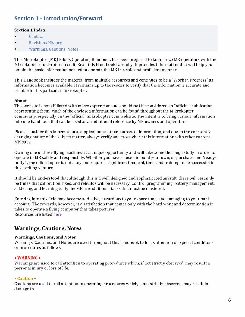
10-‐13 in props are used on the MKs and Each type is manufactured to create lift when turning in the designed direction.
11
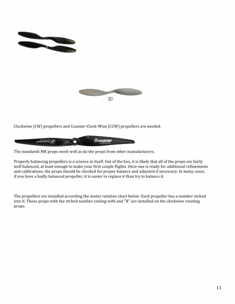
Clockwise (CW) propellers and Counter-‐Clock-‐Wise (CCW) propellers are needed.
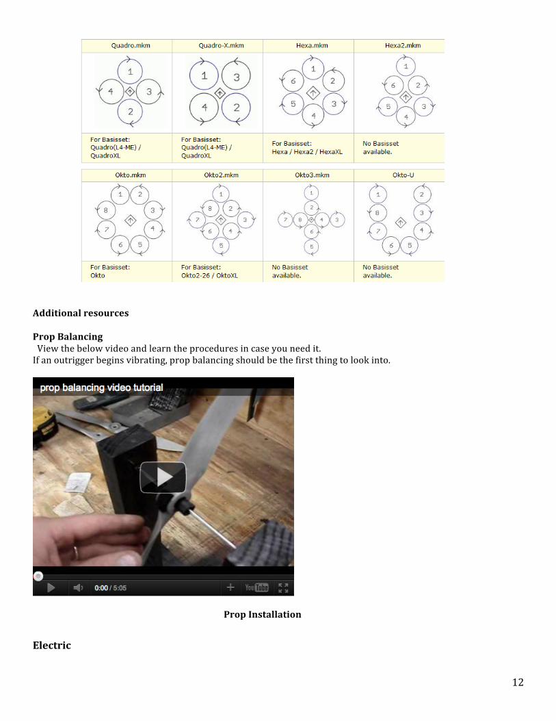
The standards MK props work well as do the props from other manufacturers. Properly balancing propellers is a science in itself. Out of the box, it is likely that all of the props are fairly well balanced, at least enough to make your first couple flights. Once one is ready for additional refinements and calibrations, the props should be checked for proper balance and adjusted if necessary. In many cases, if you have a badly balanced propeller, it is easier to replace it than try to balance it. The propellers are installed according the motor rotation chart below. Each propeller has a number etched into it. Those props with the etched number ending with and "R" are installed on the clockwise rotating props.
12
Additional resources Prop Balancing View the below video and learn the procedures in case you need it. If an outrigger begins vibrating, prop balancing should be the first thing to look into.
Prop Installation
Electric

13
Power Distribution The main power source for the MK are a LiPo batteries. These powerful batteries supply DC power to all of the electrical components of the mikrokopter.
The DC power is distributed by connection to a Power distribution Bus where all of the other components are tied. The following pages will provide an overview of the components that are powered by the LiPo batteries along with the processor boards the manage the electronics of the MK.
Batteries
The LiPo (Lithium Polymer battery) is the standard power source for the MK.
These batteries have three main things going for them that make them the perfect battery choice for the MK over conventional rechargeable batteries. • Light weight and can be made in almost any shape and size. • Large capacities, meaning they hold lots of power in a small package. • High discharge abilities capable of meeting the demanding power requirements of the MK.
On the downside the batteries are still fairly expensive compared to NiCad and NiMH, but coming down in price all the time. Although getting better.
14
• Another issue is that they don’t last that long, perhaps only 400 charge cycles (much less if not cared for properly). That said, they are getting better all the time, especially if cared for properly. • Safety issues -‐ because of the volatile electrolyte used in LiPo’s, they can catch fire or explode. • Require unique and proper care if they are going to last for any length of time more so than any other battery technology. Charging, discharging, and storage all affect the lifespan –one mistake and serious damage can be done.
General Power Wiring
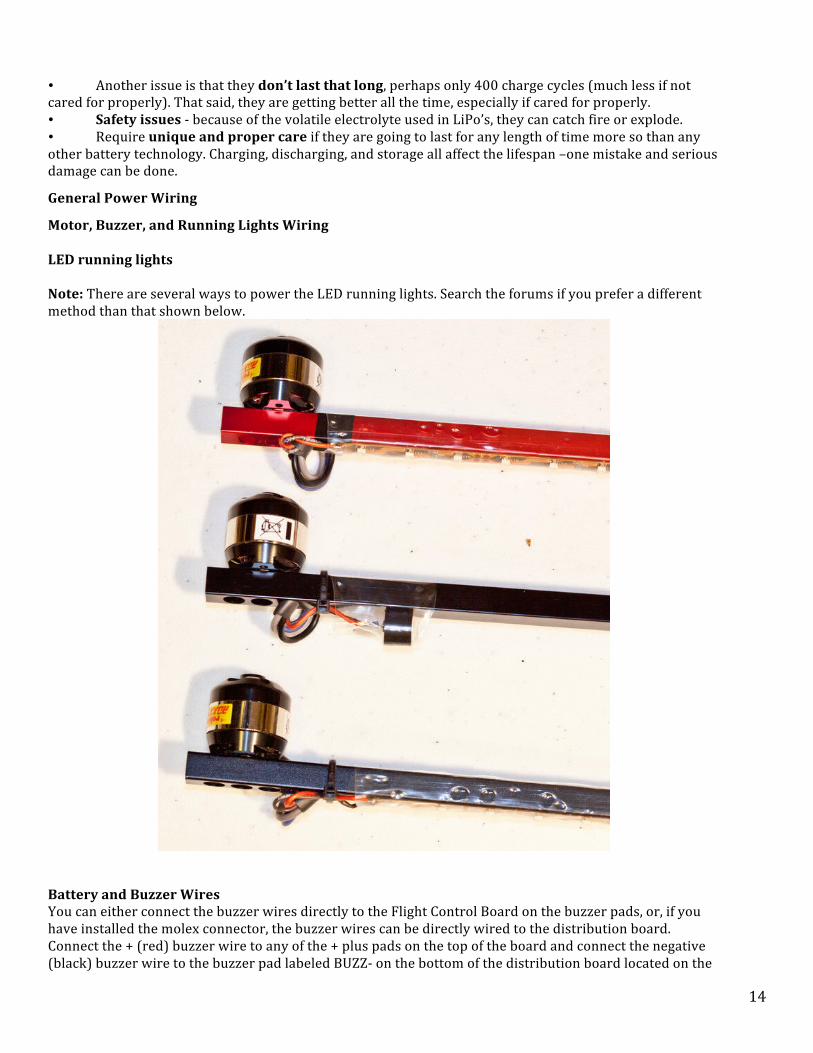
Motor, Buzzer, and Running Lights Wiring LED running lights Note: There are several ways to power the LED running lights. Search the forums if you prefer a different method than that shown below.
Battery and Buzzer Wires You can either connect the buzzer wires directly to the Flight Control Board on the buzzer pads, or, if you have installed the molex connector, the buzzer wires can be directly wired to the distribution board. Connect the + (red) buzzer wire to any of the + plus pads on the top of the board and connect the negative (black) buzzer wire to the buzzer pad labeled BUZZ-‐ on the bottom of the distribution board located on the

15
opposite side of molex connector.
Motor Wires
The order is as follows: • connect A = gray, B = blue, C = black on odd motor addresses (1,3,5,7) clockwise rotation • connect A = blue, B = gray, C = black on even motor addresses (2,4,6,8) anticlockwise direction

16
Motors
Brushless motors are the workhorse of the MK. As mentioned before, the motors use pulsed DC output from the BL-‐Controllers (ESC). Every other motor turns clockwise or counter clockwise to keep the MK stable. While these motors look relatively simple, they in fact are precision made motors that rapidly respond to power changes from the BL-‐Controller.

17

18
Electronics
The Mikrokopter is basically a flying laptop computer. In order to fly and stay in the air it must process the control commands from the pilot, distribute power to the motors to precisely control motor speed, analyze flight sensor data and maintain stability throughout its 10-‐15 minute flight time. In addition to many other functions it's the electronic board that make this all work together. The following pages will describe the function of these very sophisticated components.
Flight Control
MK-‐ Flight Control and Sensors Contents
Contents
1. 1 Overview 2. 2 Terms 3. 3 Sensor Description 1. 3.1 Gyroscopes (Gyros) 2. 3.2 Acceleration Sensor (Accelerometer-‐ACC) 3. 3.3 Atmospheric Pressure Sensor
Overview The purpose of this review is to examine the Mikrokopter Flight Control board (FC-‐Ctrl) and the various flight control sensors used on the board to maintain smooth level and controllable flight. This review does not cover the navigation systems such as the Navi Board, GPS, and Compass.
19
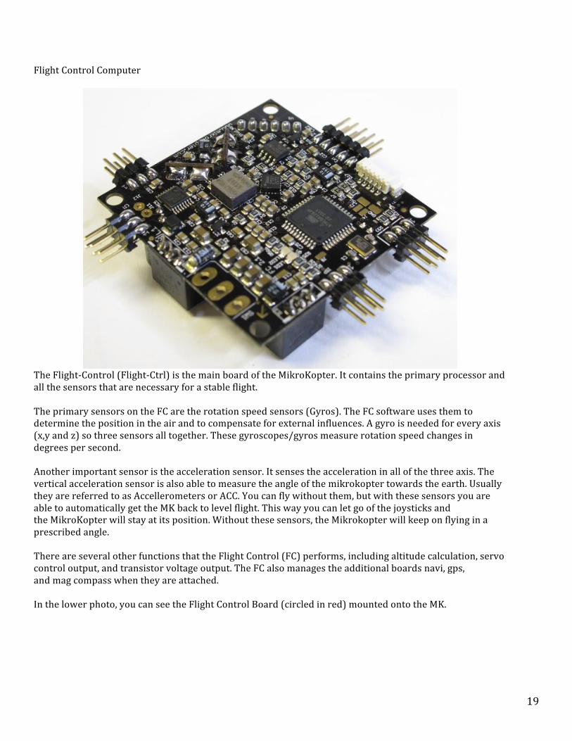
Flight Control Computer
The Flight-‐Control (Flight-‐Ctrl) is the main board of the MikroKopter. It contains the primary processor and all the sensors that are necessary for a stable flight. The primary sensors on the FC are the rotation speed sensors (Gyros). The FC software uses them to determine the position in the air and to compensate for external influences. A gyro is needed for every axis (x,y and z) so three sensors all together. These gyroscopes/gyros measure rotation speed changes in degrees per second. Another important sensor is the acceleration sensor. It senses the acceleration in all of the three axis. The vertical acceleration sensor is also able to measure the angle of the mikrokopter towards the earth. Usually they are referred to as Accellerometers or ACC. You can fly without them, but with these sensors you are able to automatically get the MK back to level flight. This way you can let go of the joysticks and the MikroKopter will stay at its position. Without these sensors, the Mikrokopter will keep on flying in a prescribed angle. There are several other functions that the Flight Control (FC) performs, including altitude calculation, servo control output, and transistor voltage output. The FC also manages the additional boards navi, gps, and mag compass when they are attached. In the lower photo, you can see the Flight Control Board (circled in red) mounted onto the MK.
20
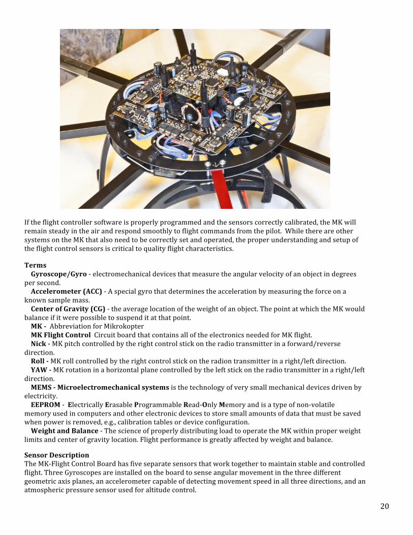
If the flight controller software is properly programmed and the sensors correctly calibrated, the MK will remain steady in the air and respond smoothly to flight commands from the pilot. While there are other systems on the MK that also need to be correctly set and operated, the proper understanding and setup of the flight control sensors is critical to quality flight characteristics.
Terms Gyroscope/Gyro -‐ electromechanical devices that measure the angular velocity of an object in degrees per second. Accelerometer (ACC) -‐ A special gyro that determines the acceleration by measuring the force on a known sample mass. Center of Gravity (CG) -‐ the average location of the weight of an object. The point at which the MK would balance if it were possible to suspend it at that point. MK -‐ Abbreviation for Mikrokopter MK Flight Control Circuit board that contains all of the electronics needed for MK flight. Nick -‐ MK pitch controlled by the right control stick on the radio transmitter in a forward/reverse direction. Roll -‐ MK roll controlled by the right control stick on the radion transmitter in a right/left direction. YAW -‐ MK rotation in a horizontal plane controlled by the left stick on the radio transmitter in a right/left direction. MEMS -‐ Microelectromechanical systems is the technology of very small mechanical devices driven by electricity. EEPROM -‐ Electrically Erasable Programmable Read-‐Only Memory and is a type of non-‐volatile memory used in computers and other electronic devices to store small amounts of data that must be saved when power is removed, e.g., calibration tables or device configuration. Weight and Balance -‐ The science of properly distributing load to operate the MK within proper weight limits and center of gravity location. Flight performance is greatly affected by weight and balance.
Sensor Description The MK-‐Flight Control Board has five separate sensors that work together to maintain stable and controlled flight. Three Gyroscopes are installed on the board to sense angular movement in the three different geometric axis planes, an accelerometer capable of detecting movement speed in all three directions, and an atmospheric pressure sensor used for altitude control.

21
The following description will further define the purpose of each device.
Gyroscopes (Gyros)
The Mikrokopter uses three MEMS ADXRS610 gyros. Of all the sensors, the gyroscopes are most important. The Flight Control software uses inputs from the gyros to determine the position in the air and to compen
sate for external influences. A gyro is needed for each geometric axis (x,y and z) of the Mikrokopter. Gyros measure the angular velocity in degrees per second. The Mikrokopter uses three MEMS Gyroscopes, each placed on a different X, Y, Z axis. The invention of the Microelectromechanal (MEMS) gyro was a breakthrough in gyro technology and allows gyro installation in everything from cameras to cell phones. The MEMS Gyro does not use a rotating mass as in older version rather it has an electostatically suspended membrane that accomplishes the same task only in a much smaller and less costly method. This new type of gyro is simpler and cheaper than conventional rotating gyroscopes of similar accuracy.

22
Acceleration Sensor (Accelerometer-‐ACC)

23
The main function of the acceleration sensor is to measure the actual tilt of the MikroKopter and to support the attitude adjustments from the gyros. The sensor measures static (gravitational acceleration) and dynamic acceleration using the LIS344ALH which is an ultra compact consumer low-‐power three-‐axis linear accelerometer. The sensor is a special MEMS Gyro that senses acceleration in all of three axis. Usually referred to as Accellerometers or ACC, you can fly without them, but with this sensor you are able to automatically get the MikroKopter back to level flight. When properly configured, you can let go of the joysticks and the MikroKopter will stay at its position. Without these sensors, the Mikrokopter will keep on flying in a prescribed angle. The ACC Sensor converts acceleration values into proportional voltage levels, which are than evaluated, along with other gyro information by the microcontroller on board the Flight Control. The sensor is also used in conjunction with the gyroscopes to determine attitude.
24
Atmospheric Pressure Sensor
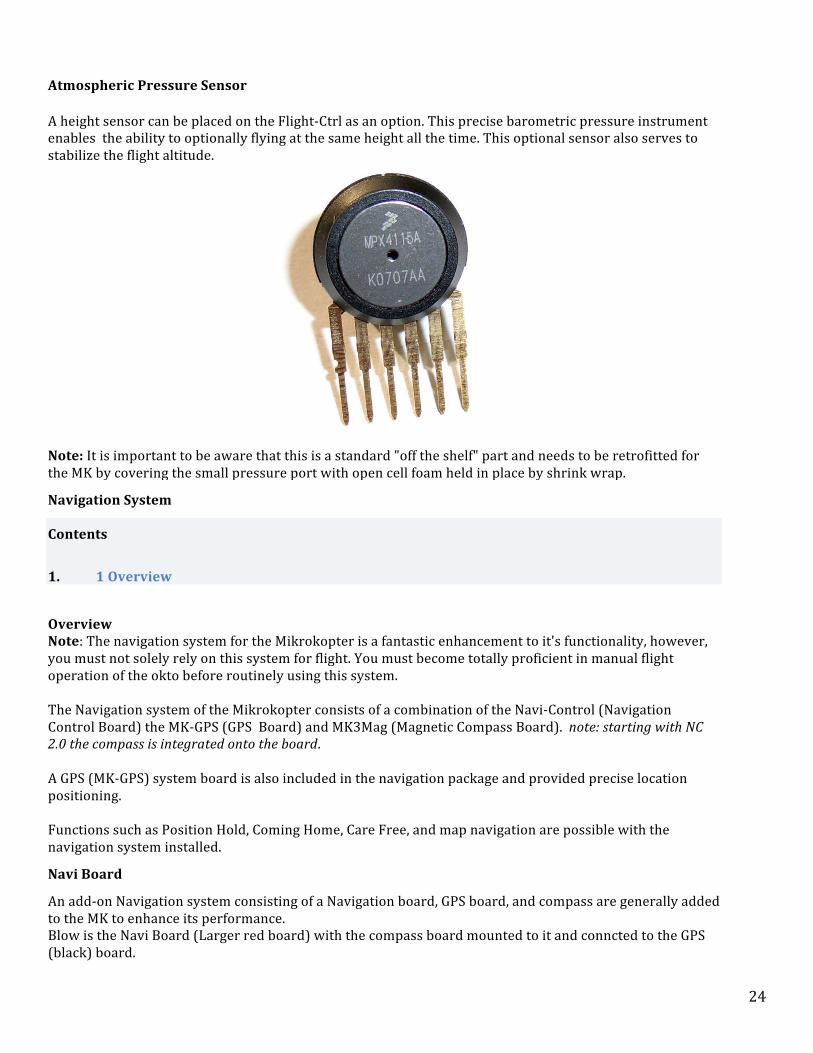
A height sensor can be placed on the Flight-‐Ctrl as an option. This precise barometric pressure instrument enables the ability to optionally flying at the same height all the time. This optional sensor also serves to stabilize the flight altitude.
Note: It is important to be aware that this is a standard "off the shelf" part and needs to be retrofitted for the MK by covering the small pressure port with open cell foam held in place by shrink wrap.
Navigation System
Contents
1. 1 Overview
Overview Note: The navigation system for the Mikrokopter is a fantastic enhancement to it's functionality, however, you must not solely rely on this system for flight. You must become totally proficient in manual flight operation of the okto before routinely using this system. The Navigation system of the Mikrokopter consists of a combination of the Navi-‐Control (Navigation Control Board) the MK-‐GPS (GPS Board) and MK3Mag (Magnetic Compass Board). note: starting with NC 2.0 the compass is integrated onto the board. A GPS (MK-‐GPS) system board is also included in the navigation package and provided precise location positioning. Functions such as Position Hold, Coming Home, Care Free, and map navigation are possible with the navigation system installed.
Navi Board
An add-‐on Navigation system consisting of a Navigation board, GPS board, and compass are generally added to the MK to enhance its performance. Blow is the Navi Board (Larger red board) with the compass board mounted to it and conncted to the GPS (black) board.

25
Although this navigation system is not needed to fly the MK, it adds very sophisticated capabilities that were once limited to only large, expensive commercial and military aircraft only a few years ago. With the added functions of GPS Dynamic Position Hold, Waypoint Navigation, Coming-‐Home, and Return Home on communication failure, the MK is on of the most modern and sophisticated aircraft of its kind. Below is a complete navigation system consisting of the Navi-‐Board, Compass, and GPS system. All are stacked on top of the Flight Control Board and connected to it with the light gray data ribbons.
MK-‐GPS
The MKGPS is a GPS-‐receiver for the Mikrokopter. Together with the NaviControl the following features are possible:
• autonomous position hold (Position-‐Hold or just PH)

26
• fly bach to start point (Coming Home or just CH) • Fly 3D-‐Waypoints (Waypoints) • Logging the flight onto the SD-‐Card • showing the actual position and speed on the 'OSD'-‐screen in the KopterTool • showing the actual distance and speed on the JetiBox • Pointing the camera to a specific point: PointOfInterest
GPS Fix
A GPS Fix is indicated by a flashing LED on the MKGPS. During the first start-‐up, the NaviCtrl will build a complete Almanac/Index. This contains satellite positions and paths. A complete cycle to build this Almanac takes 12.5 minutes. Based on the last known position the fix will from then on be built up much quicker. If the fix takes a longer time, it could be that the small battery on the GPS board is too weak. The battery is normally charged to about 3V. The battery is always charged when the GPS module is in operation. If the battery voltage is significantly lower than 3.0 V, it can be charged by providing power to the GPS module. One way is through the Naviboard's USB port (with the MKGPS connected). The ribbon cable to the FC should be removed. Another method is to power the MKGPS with 5V on one of the "5V-‐Pads" on the edge and 0V on ground (GND). Charging takes about 24 hours.
The purpose of the battery is to keep the ephemerides in RAM and the realtime clock running after power off to shorten the re-‐aquire time.

27
http://gallery.mikrokopter.de/main.php/v/tech/GPS_Shield1.jpg.html This is an enlargement of the ground-‐plane of the GPS-‐Receiver to increase the signal strenght. Also it shields the antenna against electro magnetic fields of the other electronics.
See also: GPS-‐Shield
MK-‐Compass
This is a 3-‐axis magnetic field sensor. Using the current attitude data it forms a tilt compensated Compass. The MK3Mag can be used on its own together with the Flight Ctrl to stabilize yaw control or in combination with the NaviCtrl. The MK3Mag is supported by the FlightCtrl from software version 0.69K upwards. Note: With Navi 2.0 and up, the compass is now integrated with the Navi board itself.
General Points
Caution: For use of the MK3Mag it is essential that the distance between compass and Buzzer minimum 10cm. It is best to mount the buzzer on the outer end of one of the frame arms. The highest Interfering Magnetic field is generated by: Buzzer, Motors, Power Cables and Metal Parts (In approx. this order).

28
If problems with the MK3Mag are only noticeable at higher throttle, it is likely that the interfering magnetic field is generated by power lines. Ideally the individual DC-‐lines should have very few bends and Plus/Minus should be routed parallel as their magnetic fields are then compensated by each other (Tips and Video). Operating Note: The Navi board trusts the compass data to be 100% accurate. Bad compass data will be reflected in a toilet bowling effect or worse case a flyaway. The best thing to do is to turn off all navi functions and learn how to fly manually and regain orientation based on stick and craft movements. This is where simulator training comes in helpful.
Brushless Controllers
Overview
Brushless Controller, Electronic Speed Controller (ESC)
The Mikrokopter uses brushless motors to turn the props.
BL-‐Ctrl 2.0 Top
BL-‐Ctrl 2.0 -‐ Bottom
The BL-‐Controllers are connected to the main board with a power distribution bus system (PDB) and each controller is given a unique address that is used by the main processor to communicate with the BL-‐controller. In this zoomed in picture of a BL-‐Ctrl board, you can see how the addresses are selected by flowing solder between different address tabs (ADR 1-‐2-‐3, ADR 4-‐5)

29
Below is an Okto2 Power distribution Board with eight BL-‐Cntrl's connected.
Each BL-‐Controller board is attached to it’s own associated motor and manages the power going to that motor so that it turns at the exact speed it was assigned by the FC. Brushless motors don't use brushes for energy-‐distribution to the rotor. In contrast to the motors with brushes, the magnets are rotating while the coils do not. That's why you can't use a steady DC current, DC current with precise pulses is needed to drive the motors. This current is provided by the BL-‐Ctrl. The advantages of such motors are : High efficiency and performance Less risk of interference as there are no brushless or gears. Numerous sources of motors with different power output and rpm's per Volt.

30
In order for these motors to function properly, the direct current of the batteries has to be converted to a triphasic alternating current with power output controlled so that the speed of the motors can be accurately controlled. There are numerous brushless speed controllers available on the market. However very few are available which can fulfill the special requirements: We need brushless controllers which can accept a new throttle value very rapidly (< 0.5ms) and implement it. In addition the controller has to have an I2C bus interface. Basically what happens in the motor control is that a precise speed signal is sent from the Flight Control computer to each BL-‐Cntrl (ESC). The Atmel chip on each Bl-‐control than directs the exact firing sequence to each of the six power MOSFET (transistors) mounted on the BL-‐Cntrl board. The combined firing of the MOSFETS then controls it's assigned motor using Pulse Wave Modulation (PWM). All of these instructions happen in fractions of a second and is the basis for MK flight. (read more on PWM) All this is pretty amazing, considering that this wasn't even possible ten years ago, much less affordable. The BL-‐Control board also has additional components that measure power and voltage along with operation two LED's that indicate the condition of the board electronics.
Additional Information Receiver
Each Mikrokopter must also have a radio receiver. The receiver receives the wireless signal transmitted from the pilots control transmitter and converts them to electrical signals which in turn are read by the Flight-‐Control computer. This signal contains data transmitted by pilots transmitter that contains command instruction input when the pilot moves the various transmitter sticks, switches, levers and dials. This signal is processed by the Flight-‐Control software into separate channels that will be used to control the MikroKopter. Some Radio systems such as the Graupner MX-‐20 have receivers capable of transmitting telemetry back to the pilots transmitter for real time viewing.
31
Section 3 -‐ Mikrokopter Tool NOTICE -‐ About these pages NOTICE -‐ The information presented on each of the MK-‐Tool pages is a duplicate of that presented on theMikrokopter.de MK-‐Tool pages. I have added this information for the convenience of the reader and also have attempted make a clearer translation and explain things at a deeper level if additional information is available. As you study these pages, make sure to compare what is included here to the Mikrokopter.de website and consider that the primary authority.
Index • Firmware Upgrades
• MK-‐GPS • MK-‐Tools Pages o Altitude o Camera o Channels o Configuration o Coupling o Gyro o Looping o Misc o Mixer Setup o Navi-‐Ctrl o Navi-‐Ctrl 2 o Output o Stick o User • MK-‐USB
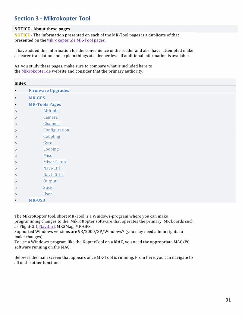
The MikroKopter tool, short MK-‐Tool is a Windows-‐program where you can make programming changes to the MikroKopter software that operates the primary MK boards such as FlightCtrl, NaviCtrl, MK3Mag, MK-‐GPS. Supported Windows versions are 98/2000/XP/Windows7 (you may need admin rights to make changes). To use a Windows-‐program like the KopterTool on a MAC, you need the appropriate MAC/PC software running on the MAC. Below is the main screen that appears once MK-‐Tool is running. From here, you can navigate to all of the other functions.

32
Download
The KopterTool is downloaded as .zip-‐file and can be used directly after unpacking. The current version can be downloaded here: MikroKopter-‐Tool
Connecting preparation
Before starting the KopterTool and beginning to make changes to the MK Parameters the MK-‐USB must be assembled and plugged into an available USB port on the PC. MK-‐USB assembly instructions can be found here: MK-‐USB
(Alternatively, the SerCon be used for the connection. This, however, requires a correct COM port. A COM-‐USB adapter can not be used !!)

33
• If your computer does not have a USB or Secon connection, you cant open/use the KopterTool! Also You cannot open the KopterTool software without the MK-‐USB being plugged into the PC.
First start of KopterTool
After the MK-‐USB is set and connected to the PC the KopterTool can be open. At the first start you see the license window:
This window displays the license agreement to use the tool MikroKopter. Also you can chose the language and the COM-‐port. The COM port should be set to the MK-‐USB. (In order to determine which COM port is assigned to the MK-‐USB, you can select in the Windows Device Managerunder COM and LPT ports.) With a "click" on Akzeptieren / Accept you accepted the license conditions, the default language setting and the COM port. Now you will see the start window of the KopterTool:
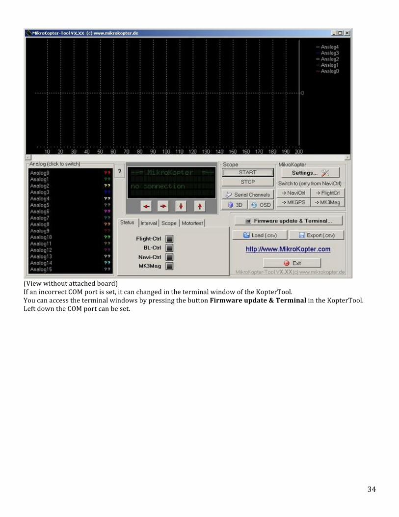
34
(View without attached board) If an incorrect COM port is set, it can changed in the terminal window of the KopterTool. You can access the terminal windows by pressing the button Firmware update & Terminal in the KopterTool. Left down the COM port can be set.

35
(With a "click" on the button Debug... you can go back to the main window.)
Connection of modules
After the connection is established to the Kopter Tool, the FlightCtrl and any other (connected) components (such as NaviCtrl, MK3Mag, etc.) can now be programmed.
Connection to the Kopter: • Flight-‐Ctrl single installed => o MK-‐USB is connected to the 10-‐pin connector "Ext" of the Flight-‐Ctrl. Flight-‐Ctrl and GPS system (NaviCtrl, MK3Mag, MK-‐GPS) installed => o MK-‐USB is connected to the 10-‐pin connector "Debug" of the NaviCtrl.
The 10-‐pin ribbon cable must be connected from terminal "1" (red-‐marked side) to the terminal "1" of each board ! The contact "1" is marked on the boards with a print.

36
Warning: If MK is being powered with a regulated power supply or LiPo, make sure the JP1 jumper on the MK-‐USB is removed before making the connection to the MK.
Caution: Especially for the initial connections it is highly recommended to use the regulated power supply because if errors occur the components will be not destroyed.
Here are some examples of how to connect the modules to the MK-‐USB.
The red arrows mark each pin "1"
FlightCtrl Navi Ctrl
NaviCtrl: MK3Mag
All of the boards shown in the pictures are individually connected so the JP1 jumper on the MK-‐USB should be closed in order to supply power to the components from the USB port.

37
First Connection
Depending on whether the Kopter is connected to the FlightCtrl or when using the GPS system on the NaviCtrl, the startup screen should look like this: Kopter with FlightCtrl, BL-‐Ctrl and Receiver.
Kopter with FlightCtrl, BL-‐Ctrl, GPS-‐System and receiver.
38
Choosing Assemblies/Settings
Assemblies/Boards
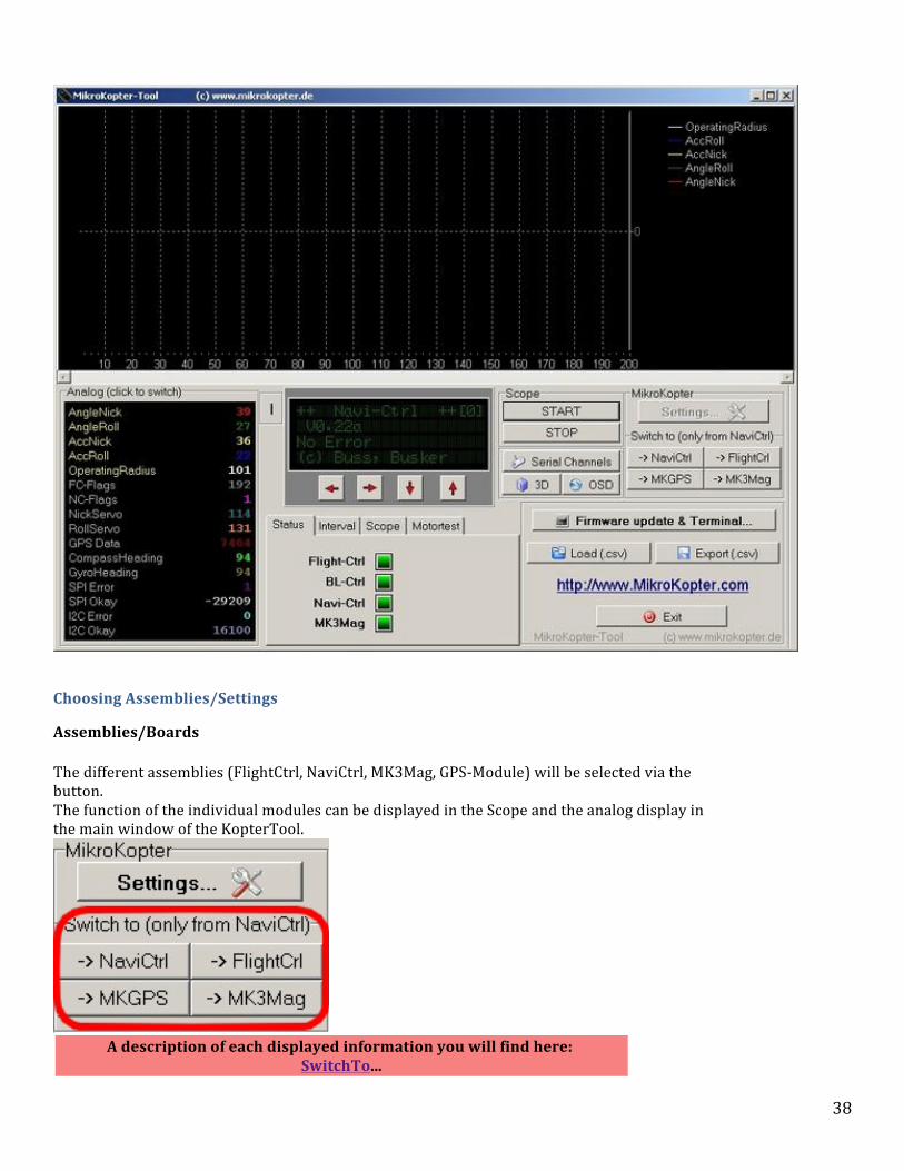
The different assemblies (FlightCtrl, NaviCtrl, MK3Mag, GPS-‐Module) will be selected via the button. The function of the individual modules can be displayed in the Scope and the analog display in the main window of the KopterTool.
A description of each displayed information you will find here:
SwitchTo...

39
Settings
All settings to the Kopter are made on Settings.
If all modules are connected together the settings for all components are made centrally. To turn into the settings (Settings...) you must choose the FlightCtrl.
INFO If you select the Settings and see this window...
... then the KopterTool Version is not compatible to the software version on the FlightCtrl and/or NaviCtrl. Then you should update the FlightCtrl / NaviCtrl with the latest software version. (Update) (Alternatively, it could also be used an older version of KopterTool.)
Scope
In the Scope window the functions of the modules are checked. You can determine by selecting the individual functions which scope is displayed.

40
Scope Selection
A click on Scope opens the selection window. Here, the individual functions can selected to be displayed in the scope. Depending on the selected module various functions can be selected.
FlightCtrl NaviCtrl MK3Mag
Also you can select on the analog display the value you need with a "right click" of the mouse on it. This will then change the font color of the selected value. Here are the first 5 values are selected:
Scope Start/Stop
The scope on the scope window will be started and stopped by pushing the buttons START and STOP.
41
Scope Window
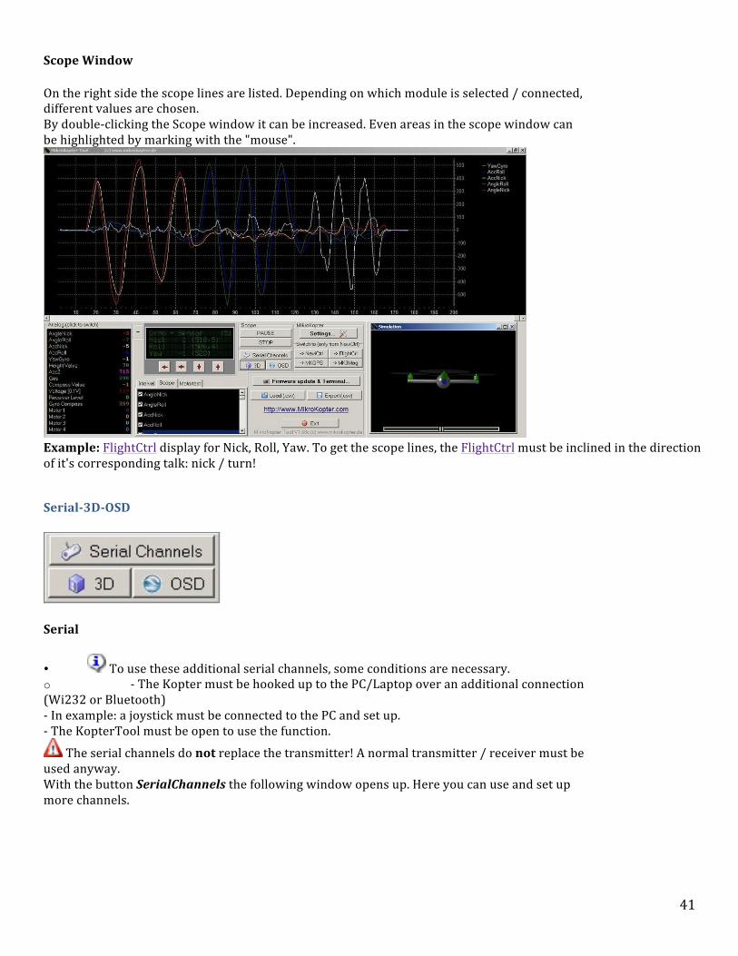
On the right side the scope lines are listed. Depending on which module is selected / connected, different values are chosen. By double-‐clicking the Scope window it can be increased. Even areas in the scope window can be highlighted by marking with the "mouse".
Example: FlightCtrl display for Nick, Roll, Yaw. To get the scope lines, the FlightCtrl must be inclined in the direction of it's corresponding talk: nick / turn!
Serial-‐3D-‐OSD
Serial
• To use these additional serial channels, some conditions are necessary. o -‐ The Kopter must be hooked up to the PC/Laptop over an additional connection (Wi232 or Bluetooth) -‐ In example: a joystick must be connected to the PC and set up. -‐ The KopterTool must be open to use the function.
The serial channels do not replace the transmitter! A normal transmitter / receiver must be used anyway. With the button SerialChannels the following window opens up. Here you can use and set up more channels.

42
To each channel (Ch1: ... Ch12:) functions can be assigned to the joystick. Those you can choose under Axes,Buttons or POV. So that the functions are transferred to the copter it must have a hook at the bottom "sending the serial channels are active" to be set. To each channel now a FUNCTION / POTI can be assigned. This can be done in the Settings: Channels.
3D
After a click on the 3D-‐Button the indicator of the center of gravity (Balance) and the simulation of the Kopter will be displayed.

43
Both ads will appear when you are connected to the FC and than click the 3D button (maybe click on "FlightControl" before). In the display of the center of gravity you can control if the Kopter has it's center of gravity in the middle or at a different spot. For this you can connect your Kopter with e.g. a Bluetooth or a Wi232 to the PC. Now you can hover with your Kopter and controll the center of gravity (a second person can do this for you). If the focus of the MikroKopter is not on the main thrust of the engines (usually the center) the point walks out. Very interesting: Yaw (upper scale). If the frame is not really straight the MK is yawing all the time against it.
OSD
With the OSD-‐display multiple functions can be used. In the upper display, in example, the height of the Kopter, the speed, battery level, distance to the start point, etc. can be displayed. In the lower field maps can be loaded. The position of the Kopter can be displayed. Also, waypoints can be entered and the Kopter can fly automatically.

44
For the on-‐screen display ( OSD ) a data connection is required for the Kopter. This can be done via Bluetooth or
Wi232. For a waypoint-‐flight the radius is limited to 250mtr! Informations how to use the OSD for e.g. load a map, waypoint setting, POI
setting or many other functions can be found here: KopterTool OSD...
Terminal-‐Window
The Terminal Window will open through a click on Firmware update & Terminal.
The Terminal Window.

45
COM-‐Port
Here you can set up the COM-‐Port for the MK-‐USB. Only if this is correct set up you will have a connection between the MikroKopter (or individual components) and the KopterTool.
With the green dot on the left side of the COM port, the COM port can be ended and been restarted. Is the dot green, the COM-‐PORT is "ON".
Debug
With the Debug button you can switch back to the KopterTool Main-‐Window.
Choose language
In the first time the KopterTool is set up automatically by the detected PC speech.
If you decide to have a different language for the KopterTool you need to click on the button to set it up. In the next window that opens you can choose the language you need. With Restart the KopterTool starts with the new language.

46
• More languages In the program directory you will find the language files as "language_XX.dat". (XX = country code) This is a simple text file that can be edited with a text editor. Everyone can even modify the files or translate a new language. The format is quite simple:
english text = translated text e.g. Communication timeout! = Délai de communication trop long
The best thing is for a new language to use an existing language file, renames it and start the compilation. If there is no translation for a word in the file, it automatically displays the text English.
Anyone who wants can send us new language files, and in the next release it will be taken over...
Latest Software download
The latest software for the individual components of the Mikrokopter can be downloaded with the KopterTool.
A click on the loupe opens the necessary window. An explaination of the download you will find here:
Software Download...
Latest Software update
After the actual software is downloaded you can place it into the necessary module (FlightCtrl, NaviCtrl, etc.) You need to click on the button Update Software (serial)...
An information about the Update you can find here:
Software Update...
Reset -‐ EEPROM initializing
To reset the modules (FlightCtrl, NaviCtrl, etc.) back to the standard settings,

47
you can do it on a click of the button with the red triangle All settings will be reset but not the channel allocation.
After a "BIG" Software Updates you should initialize the EEPROM. Since this usually have altered much of the default values you should not store old settings. Here, the settings should be set more new. Of course, then you should calibrate the ACC once again.
Firmware Upgrades
Overview:
Firmware is the fixed programs and/or data structures that resides on each board processing chip to control various board functions. The MK will not operate without correctly installed firmware as it is essentially the brains of the board. While Firmware upgrading may seem overwhelming at first, take your time and follow these instructions carefully and you should have no problems. Info: What is a HEX file? HEX is a file format for conveying binary information for applications like programming microcontrollers, EPROMs, and other kinds of chips. It is one of the oldest file formats available for this purpose, having been in use since the 1970s Note: BL-‐Ctrl Firmware An update of the BL-‐Ctrl is seldom needed and not part of a typical Firmware update! For an update or to control the BL software , the BL-‐Ctrl must be connected directly to the MK-‐USB. (see: http://www.mikrokopter.de/ucwiki/en/SoftwareUpdate) if you need to update or check BL-‐Ctrl Firmware) Warning WARNING: The connection to MKTools should be via the USB cable (NOT WIRELESS) If you missed this warning and tried upgrading with wireless Xbee and now cannot connect to the Navi board, all is not lost-‐-‐-‐ see this post Note: It is recommended to use a regulated power supply that is set to a low mA limit for this process. WARNING: Props should be removed as a software glitch could cause motor start. (at least tie the MK down and stay clear)
Update Steps: 1) Confirm in MKTools, which firmware versions you have. 2) Download all of the latest firmware versions for Navi Ctrl, Flight Ctrl, MK3Mag ( MK3Mag is integrated into NC 2.0 board -‐ also, MK3Mag firmware is not updated after FC V.086/NC.86). Also, download the latest MKTools (you will need to use this once the upgrades are done) Place the files into a separate folder in your PC and remember where you put them. (Alternatively, you can get the latest firmware from within MK-‐Tools -‐ See these instructions)
Note: Save your old values
• In MKTools, make screen captures or write down of all of your settings for future reference.Major upgrades will

48
reset all of the software values to original settings and any changes that you have made will be lost. Note: The newest version of Firefox (4.0) has a screen capture feature built in.
• It is recommended that you re-‐check and manually re-‐enter all of your software changes for any upgrade. You should never import settings of previous versions via the KopterTool. The settings should be done manually!
• The compass must be re-‐calibrated using the new version of the calibration procedure. It would also be a good idea to do a sensor calibration at this time also. 3) Close down all unnecessary programs and processes you have running. If you are doing this on a laptop, make sure the battery is charged. 4) Click Firmware update & Terminal Note: Use your existing version of MKTools not the latest download.
5) The terminal window pops up

49
6) Click Update Software (serial) Note: Where are the Hex Files? The current software of the individual components can be downloaded easily over the KopterTool. This describes how to download the files via the KopterTool: Software Download 7) Navigate to the folder where you downloaded the latest firmware.

50
The firmware should be updated in the following order: a) Navi-‐Ctrl b) MK3Mag (skip this step if you are upgrading from FCV0.84 to FC V 0.86) c) Flight-‐Ctrl 8) The process takes about a minute or so per firmware update. At the end each of the updates there is a verification and confirmation beep from the mikrokopter. Note: If you get a failure at this point -‐ see this info Note: If you open a updatefile, the KopterTool detects automatically (on the file name) which file it is and for what this board is used. So for example if you try to program the NaviCtrl firmware into the FlightCtrl, it will give you an error message. 9) Check all the settings as they will all be the defaults of the new firmware. For example, the default model is for a Quad, If you have an Okto (the configuration file for the different setups are within the directory you extracted MKtools to). 10) You'll need to re-‐due the ACC calibration (left stick up and to the right) with the kopter level. 11) Recalibrate the compass. (This Process is new for FC version .084) 12) Install and open the newest version of MKTools and verify that the boards are communicating with each other, all settings are still there, and the correct versions of firmware is being displayed.
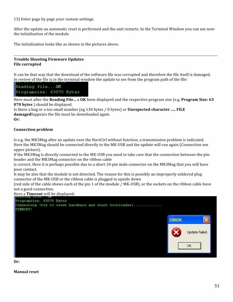
51
13) Enter page by page your custom settings. After the update an automatic reset is performed and the unit restarts. In the Terminal Window you can see now the initialization of the module.
The initialization looks like as shown in the pictures above.
Trouble Shooting Firmware Updates File corrupted
It can be that way that the download of the software file was corrupted and therefore the file itself is damaged. In review of the file is in the terminal window the update to see from the program path of the file:
Here must after the Reading File... a OK been displayed and the respective program size (e.g. Program Size: 63 070 bytes ) should be displayed. Is there a bug or a too small number (eg 130 bytes / 0 bytes) or Unexpected character ..... FILE damaged!appears the file must be downloaded again. Or:
Connection problem
Is e.g. the MK3Mag after an update over the NaviCtrl without function, a transmission problem is indicated. Here the MK3Mag should be connected directly to the MK-‐USB and the update will run again (Connection see upper picture). If the MK3Mag is directly connected to the MK-‐USB you need to take care that the connection between the pin-‐header and the MK3Mag connector on the ribbon cable is correct. Here it is perhaps possible due to a short 10-‐pin male connector on the MK3Mag that you will have poor contact. It may be also that the module is not detected. The reason for this is possibly an improperly soldered plug connector of the MK-‐USB or the ribbon cable is plugged in upside down (red side of the cable shows each of the pin 1 of the module / MK-‐USB), or the sockets on the ribbon cable have not a good connection. Here a Timeout will be displayed:
Or:
Manual reset

52
The connection is fine but the automatic update does not work anyway? If after "Connecting (try to reset hardware and start bootloader)..." is not an "OK" coming up after ~3 to 4 dots than you can do as follows:
• connect the PCB (i.e. FC) over the ribbon cable direct to the MK-‐USB (not over a wireless connection!). For the BL-‐Ctrl use the connector on the side of the MK-‐USB!
• remove jumper from MK-‐USB • In the KopterTool select the appropriate file and start the update • place the jumper while the dots been displayed
• Now a OK should be behind the dots.
(After switching on the board always the bootloader starts first -‐ then detects the update from the KopterTooland performs the update.)
• Repeat if it don't work. Timing is the matter of fact.
If it comes to frequent interruptions with error-‐messages the computer can be also the problem.
If a laptop is used and the power for the modules is supplied over the MK-‐USB the power can be not sufficient. Here you should either provide the module with an external power supply or a lipo. Or a PC is used for the update. Following is a helpful tutorial from Error! Hyperlink reference not valid.
Quadrocopter Tutorial -‐ Upgrading Firmware with MKTools from Quadrocopter on Vimeo.
MK-‐Tools Pages
Notice -‐ About these pages NOTICE -‐ The information presented on each of the MK-‐Tool pages is a duplicate of that presented on theMikrokopter.de MK-‐Tool pages. I have added this information for the convenience of the reader and also have attempted make a clearer translation and explain things at a deeper level if additional information is available. As you study these pages, make sure to compare what is included here to the Mikrokopter.de website and consider that the primary authority.
Parameter Page Index • Altitude • Camera

53
• Channels • Configuration • Coupling • Gyro • Looping • Misc • Mixer Setup • Navi-‐Ctrl • Navi-‐Ctrl 2 • Output • Stick • User
In these pages are the different configuration parameters of the Mikrokopter Tool. Making Setting Changes Note: The Mikrokopter should fly very well with the default settings. Prior to changing other parameters, please make sure that you have properly calibrated the gyros, accelerometers, compass and checked balance. Keep of copy of your current settings prior to any changes so that you can go back to a working model without having to reset completely back to the factory default settings. When adjusting parameters, make changes in minor increments and than test them before continuing changes.
Easy Setup Page:
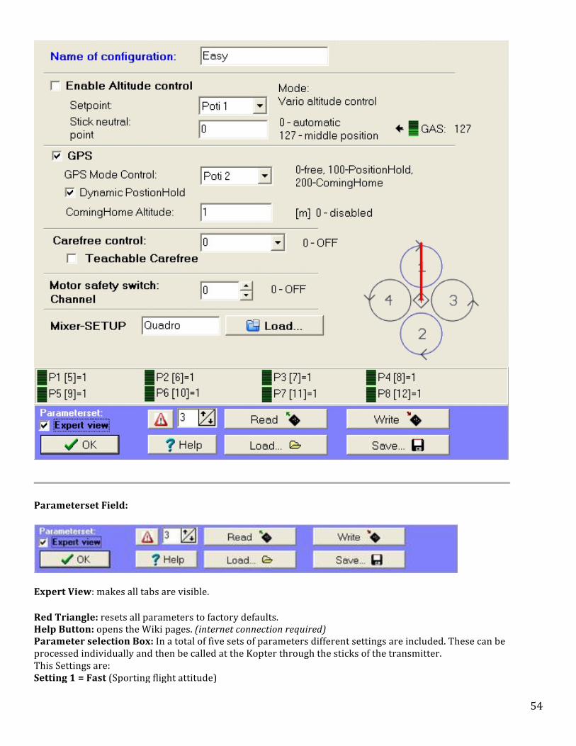
54
Parameterset Field:
Expert View: makes all tabs are visible.
Red Triangle: resets all parameters to factory defaults. Help Button: opens the Wiki pages. (internet connection required) Parameter selection Box: In a total of five sets of parameters different settings are included. These can be processed individually and then be called at the Kopter through the sticks of the transmitter. This Settings are:
• Setting 1 = Fast (Sporting flight attitude)

55
• Setting 2 = Normal (Average flight attitude) • Setting 3 = Easy (Basic flight attitude) • Setting 3 = Easy (Basic flight attitude) • Setting 3 = Easy (Basic flight attitude)
Each setting can be renamed in the Configuration page under Name of configuration. This is maybe necessary if you change a single setting with "your" changes.
Note: This is useful for example for different payloads, sporty flying or camera-‐flight etc.
Read: loads the current settings that already in the mikrokopter. Write: Saves a setting change. The MikroKopter acknowledged this with a appropriate number of short beeps. Note: Each set must be saved individually! Save: Saves the current Parameter Set. Load: Loads a selected Parameter Set from the PC. Note: The parameter sets can be viewed with a text editor and printed, too. Thus, it is possible to view the parameter sets without a laptop while flying.
Radio Transmitter Parameter Selection: parameter sets can be loaded using the transmitter by moving the sticks into the following positions.
• Setting 1 = Throttle up / Yaw left + Roll left • Setting 2 = Throttle up / Yaw left + Nick up / Roll left • Setting 3 = Throttle up / Yaw left + Nick up • Setting 4 = Throttle up / Yaw left + Nick up / Roll right • Setting 5 = Throttle up / Yaw left + Roll right
Warning: All settings are preset. If changes are made to the settings, please take care, that you use valid data. If you load a setting with wrong data, the Kopter can malfunction or crash!
Warning: Don't change a setting during flight (e.g. using Wi.232 etc.) -‐ the MK can be lost or crashed! always land first, then write settings and start again.
Altitude

56
The height control of a Mikrokopter is based on measuring the air pressure. A PID controller controls the overall thrust of all the rotors so that the measured air pressure (altitude) remains constant. There are two different options for the altitude control which can be selected.
Selection of functions
• Enable Altitude control o Unlocks the height control in the software (has the same effect as the setting in Configuration) and makes the
Height Control option available if selected by transmitter switch. • Type of height control o Height limitation control § With Enable Altitude control selected, the altitude control software is activated and the MK Flight Control can now
use the barometric sensor to assist flight.
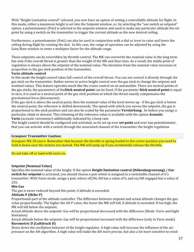
57
With "Height Limitation control" selected, you now have an option of setting a controllable altitude for flight. In this mode, either a maximum height is set into the Setpoint window, or, by selecting the "use switch as setpoint" option, a potentiometer (Poti) is selected in the setpoint window and used to make any particular altitude the set point by using a switch on the transmitter to trigger the current altitude as the new desired ceiling. Furthermore, a potentiometer (Poti) can also be used in conjunction with a dial or lever to raise and lower the ceiling during flight by rotating the dial. In this case, the range of operation can be adjusted by using the Gain/Rate window to enter a multipier factor for the altitude range. These setpoints can be overridden by throttle control. The MK can overwrite the nominal value in the long term but only if the overall thrust is greater than the weight of the MK and thus rises. As a result, the stable point of regulation is always above the setpoint of the nominal value. The deviation from the nominal value increases in proportion to the gas stick position of the transmitter.
o Vario altitude control § In this mode the height control takes full control of the overall thrust. You can not control it directly through the
gas stick on the transmitter. Rather serves to active height control over the gas stick to change the setpoint and nominal values. This feature operates much like the cruise control on an automobile. There are neutral points of the gas sticks, the parameters of theStick neutral point can be fixed. If the parameter Stick neutral point is equal to zero, it is used as a neutral point of the gas stick position at which the thrust exactly compensates the gravitational force (Hoverpoint). If the gas stick is above the neutral point, then the nominal value of the level moves up -‐ if the gas stick is below the neutral point, the reference is shifted downwards. The speed with which you moves the setpoint, the gas is proportional to the stick position and can also be scaled by the parameter Verstärkung . So before you assign a particular climb or descent. This trimming of the reference value is available with the option Acoustic Vario (acoustic variometer) additionally indicated by a beep rate. The height control should be configured and activated, so be set up over set point and over one potentiometer, that you can activate with a switch through the associated channel of the transmitter the height regulation.
Graupner Transmitter Caution: Groupner MX-‐20 users-‐ Remember that because the throttle is spring loaded to the center position you need to hold it down once the motors are started. The MK will jump up if you accidentally release the throttle. Do not take off or land with vario on.
• Setpoint (Nominal Value) o Specifies the nominal value of the height. If the option Height limitation control (Höhenbegrenzung) / Use
switch for setpoint is activated, you should choose a poti which is assigned to a switchable channel of it's transmitter. With Vario-‐mode, assign a poti, where off/No AH has a value of 0, and on/AH engaged has a value of 255.
• Min Gas o The gas is never reduced beyond this point, if altitude is exceeded. • Altitude P (Höhe P) o Proportional-‐part of the altitude controller. The difference between setpoint and actual altitude changes the gas-‐
value proportionally. The higher the Alt P value, the faster the MK will fall, if altitude is exceeded. If too high, the MK will fall below the setpoint.
o Actual altitude above the setpoint: Gas will be proportional decreased with the difference (Mode: Vario and hight limitation)
o Actual altitude below the setpoint: Gas will be proportional increased with the difference (only in Vario mode) • Barometric D (Luftdruck D) o Slows down the oscillation behavior of the height regulator. A high value will increase the influence of the air-‐
pressure on the AH-‐algorithm. A high value will make the AH more precise, but also a lot more sensitive to wind-‐
58
gusts. • Z-‐ACC o Slows down the oscillation behavior by using the z-‐axis of the MK. • Gain/Rate (Verstärkung/Rate) o Allows greater altitudes where the value is increased. The setpoint is multiplied by this value. • Hover variation (Schwebe-‐Gas +/-‐) o Limits the regulator output to the environment of the Hoverpoint, smaller values calm the scheme but also the
agility. • GPS-‐Z o Slows down the vibration response using the GPS altitude values. • Stick neutral point o Neutral point of the gas sticks about the climb and descent rates for the Vario-‐height control. If the value is zero,
the natural Hoverpoint of each MK is used.
Warning: If you start or land with a switched on level control the ground effect is due to the risk of feedback and thus the risk of swinging up with the height control near the ground, which can lead to unintended hops.
For more information on checking, installing, and packaging the height sensor can be read here: height sensor
Camera

59
Camera Control Page The Camera Control page is where you set the parameters pertaining to operation of the camera mount..Most camera mounts used on the MK are designed with two servos, one to control forward tilt (nick) of the camera platform, either by the operator or by the Flight Control gyros-‐-‐-‐usually both. The pilot tilts the camera down to a desired angle while the Flight Control keeps the platform steady in the forward axis of operation, both work together at the same time.. Servo control .*** "Servo control" sets the level point of the mount. This is were you adjust the camera level after you have done the initial Acc calibration (left stick up and left)...You can either set a fixed value to align the camera mount or, assign a potentiometer (Poti) in order to control the level point from the ground while the MK is in flight..As I mentioned earlier, usually a Poti is used for the Nick but not the roll...Nick Compensation .Nick compensation can
60
be defined as "responsiveness" or “sensitivity” to the MK tilt. .The FC will try to compensate the tilt of the mikrokopter to keep it level. You can still of course control the roll and tilt if you have it set up this way. Your command will be added to the compensation. The end result is that you can control the camera mount by tilt and roll without noticing that the MK is actually moving...So than, Compensation adjusts the MK so that the mount stays level when tilting the MK either by command or wind correction. Operating Note: Compensation can be considered the influence of the pitch angle and roll angle to the corresponding servo. -‐-‐-‐it sets the amount of degree of correction-‐-‐-‐Not all camera mounts use the same gearing / ratios, so you have to adjust for this -‐-‐ Too little .. mount won’t compensate enough ... and "undercompensate" ... too much .. and it will be "overcompensate".... you have to tweak until its just right ... In addition nick comp level may not be same as roll comp level ... may have different gearing (depending on mount used) .Example Video: http://youtu.be/EkN9IrfXxC4.. Invert direction .If the rotational direction of the servos are upside down, the direction can be inverted..Also need to be sure its compensating in right direction ... Check or uncheck "invert direction" box if needed .. .. be sure to "write" settings between each change. ..Servo min. "Servo Min" is how far the servo will be allowed to travel when tipping the MK hard to the left or right. Adjust so that extremes do not allow mount to make contact with anything on your MK. Minimum value as a stop... Servo max .Maximum value as a stop...Servo refresh rate.Some servos can not be controlled with fast values. (the smaller the value, the faster the drive). With the FlighCtrl ME 2.0/2.1 up to 5 servos can be issued. The output is performed sequentially..The "servo refresh rate" controls also the maximum number of servo channels. I.e. a value of 3 are only the first 3 servo channels...Then Servo4 and Servo5 are grayed out in the KopterTool and can not be used... Manual control speed. If you are using a potentiometer for controlling nick, you can adjust the speed of the movement by selecting a larger/smaller number. a smaller number will be slower and smoother..The pitch and roll compensation which is performed on the FlightCtrl is not involved -‐ which is still very fast...NOTE: The Nick-‐/Roll servos are only activated after calibrating the gyro....Basic Setup.During assembly, the servos are connected to the Flight Control board by connector SV2 -‐Servo1 (Nick) and SV3 -‐ Servo2 (roll).. ..Note: Additionally, you can connect three more servos: SV3 (Servo3) and SV4 (Servo4/Servo5) that can be used for other functions such as camera triggers...Note: For camera yaw control (pan right/left), the entire MK is used and directed by the pilot using yaw control... About Servos Note: A Servo is a small device that has an output shaft. This shaft can be positioned to specific angular positions by sending the servo a coded signal. This is how flight controls are operated on model aircraft. The roll servo is used to keep the camera platform level on the roll axis. Although it is possible to have roll operated from the ground, it is typically only controlled by input from the Flight Control computer. So, basically, the camera mount uses data from the same servos that keeps the mikrokopter level, the Camera Parameter page just tells the flight control how to use this information depending on the settings that you make on the page. .Tip: Servo arm linkage should be approximately at 90 degree angle down near the servo..If it is not, you can unscrew the servo arm and reset it to another tooth... ..Operating Note: compensation: actually the most stable video is with very little Nick and Roll compensation and no IS in Camera, this usually causes strange artifacts..most

61
of the really Clean videos you see have Post Production IS done to them. but not for vibration more for just the small, here and there changes in direction the MK can do to stable itself. It takes a very steady flying hand. Flying not on GPS will be smoother than with GPS. .Depending on the Gain adjustments on the GPS in the MKtool it can give a bit of a bump when it hits the limits of drift. So its constantly moving a bit on GPS hold. This can be calmed down quite a bit with some slight tweaking of the Navi settings. It really depends on the final weight of your system and how well balanced and calibrated your system is..But in a good solid wind it will actual be more stable. It likes to have something to push against.... Operating Note: If you are looking for vibration. with well balanced props and well balanced payload you just wont see very much if you are using a good Camera mount with vibration dampeners...-‐-‐-‐-‐-‐-‐-‐-‐-‐-‐-‐-‐-‐-‐-‐. Mounting Hint: SERVO Centering -‐-‐ In order to make the initial installation of a servo easier, you need to zero your servo's control at a center operating position. ( operating range on both sided of the servo center set-‐point)..Power up the servo without the little white gear arms connected to the servos and set your channel to a center position, then connect the arms to the mount. the white arms will fit in differently depending on which way to turn them. If you can't get the right angle turn the arm over and it will fit that half notch you need. This will assure some operating range of the servo shaft...Now you can do some adjustment with the radio to make final adjustments, but, be careful not to exceed the range of the servo...Operating Note: As far as how you know what the camera is shooting... That’s when you need a video transmitter to send whatever the camera sees. Most cameras come with some sort of 'live view' and have video out. This is you best option.. Add a shutter control and you have your FPV aircraft...Tilt and roll compensation come in very handy in the wind. A MK on GPS hold can be sitting at a 30 degree angle or so fighting the wind..-‐-‐-‐-‐-‐-‐-‐-‐-‐-‐-‐-‐-‐-‐-‐-‐-‐-‐-‐-‐-‐. Initial Centering.: Initial centering adjustments can be done with the roll cradle and tilt servo loosened so the servos won't drive the platform in either axis, then use a servo tester to send a center point signal to the servo and manually center the travel of the shafts as close as possible. If you don’t have a servero tester, turn the servo shaft by hand and estimate to center location. For instance, the roll pot on an AV130 is a 10 turn pot so go to one end of travel and reverse it by 5 turns and you should be very close to center, make sure to do that first with no power applied to the servo. You can find absolute center once power is applied to the servo by moving the pot a tiny bit in each direction until the servo stops moving, you are now at center travel of the pot and also of the roll servo. Next set the mechanical center for the platform as close as possible by leveling the camera platform in the mount frame and tightening the cradle rollers so the rack gear is properly meshed with the pot and servo gears making sure to not move either the pot gear or cradle in the process. After that tighten the tilt servo belt tension after setting the trim pot centering, don't worry about getting either axis perfect just get as close as you can for the moment (You could also just plug the servo into a port on a normal RX with that channel centered in the TX adjustments if you don't have a servo tester handy)... Servo Control Setting. After connecting up the servos and powering the MK, use the servo control setting in the camera tab of MKtool to fine tune the center of the roll axis making sure the MK is level first. ..Compensation Settings.While still connected to MKtool you can properly set the compensation setting as well. Once you have established center on both axis, prop up the landing gear on one side of the MK within the physical travel limits of the camera platform roll axis, now check the leveling. If the platform is not level adjust the servo roll compensation setting in the camera tab until it is. Once you have it level, go back and check level at center (it shouldn't change) and then prop up the opposite side at the same height as the other side was and check to make sure the platform is level there also, again it shouldn't be off unless there is a mechanical problem with the mount. In the case of some mounts with direct linkage movements like the Hisight II you may have to play around with the linkage adjustment to get linear movement across the range of travel before the compensation setting will work correctly. Now you can repeat the process for the tilt axis using the same method. When you're done the platform should remain level at all times within its travel limits as you move the MK around in different axis, you WILL see the difference in recorded video if you have not done this adjustment...The goal is to have the servo at the center neutral position with theoretically equal travel in both directions from that point, in practice there will rarely be equal amounts of travel to either side usually due to some mechanical restriction like the tilt servo hitting the upper framework as

62
the cradle rotates.
Channels
The FlightCtrl can handle up to 12 channels from the transmitter, and up to 12 channels via a serial input. These serially transmitted channels from the transmitter can be checked in this view and the MikroKopter functions can be assigned. To control the copter 4 channels are required: GAS, YAW, NICK, ROLL
Channels

63
from the transmitter
Depending on the transmitter / receiver, a different number of channels are used. (See Sender) If the receiver is connected properly and the the transmitter hooked up right to the FlightCtrl, you can check on the function of each channel.
Below is shown the channel 1-‐12. Above the current values of each channel is displayed: 0 (down) / 127 (middle) / 254 (above). The bar graph also shows you the values of each channel.
Serial Channels
The FlightCtrl can also analyze up to 12 channels via serial communication (e.g. from a joystick). These can be used like normal transmission channels, so the POTI functions (POTI1 -‐ POTI8) are assigned. Over here, for example, you could control a camara mount.
Only the control functions (GAS, YAW, PITCH, ROLL) can not be assigned to these serial channels.
To use these additional channels you must have a connection between Kopter and PC. These connection you can set up with the Bluetoothmodul or the Wi232 for your use. The KopterTool must be open for use! For the control at your PC a joystick should be installed. The joystick must be connected and assigned to the channels. Here you need to click in the KopterTool on Serial Channels
Now you can assign the individual functions.
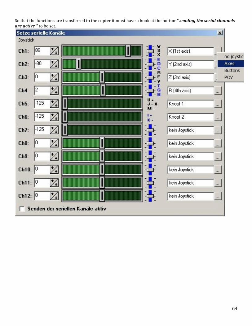
64
So that the functions are transferred to the copter it must have a hook at the bottom" sending the serial channels are active " to be set.

65
Function / Channels
To each channel now a FUNCTION / POTI can be assigned. The first 4 channels are for GAS (1), YAW (Yaw) (4), NICK (3), ROLL (2) set. The remaining channels / serial channels you can freely assign to POTI1-‐8.

66
The allocation is also shown in the lower POTI bar.
By clicking on the downward triangle the channel, serial channel or a waypoint event(WP Event) will be selected. (The WP Event is listed under OSD
´
MotorSafetySwitch
In the past it happened again and again that the pilot had turned off the MK in the air by pressing the gas yaw lever into the lower left corner by a mistake. Especially during rapid descent and yawing at the same time these mishaps happen. Now you can lock the switching ON and OFF of the engines on a different switch at the transmitter. The ON / OFF is then latched when the channel value >35 (for example a switch is turned on).

67
Tipp: You can use this function for example to merge with the channel of height control, then you can not disable the activated height control accidentally.
Advanced signal reception test
The "Advanced signal reception test" was especially installed for the 35/40MHz-‐Systems. There at the range limit (or disorders) it caused undefined values since there is no backup of the data by a similar protocol.
• Erweiterte Empfangssignalprüfung (Advanced receiver signal validation) o RC-‐routine: reception loss is safely recognized § It is checked whether the numbers of channels changes in flight -‐> this should never happen in the error-‐free
operation § in the first 500ms at a disorder an old receiving data packet (the penultimate) is used instead of the last § it is switched to a minimum of 1 second on "faulty reception"
The "Advanced receiver signal validation" checks on the receiving signal more detailed. Thus, for example "suspect status" (such as changing the number of detected channels or disturbance / removal of the timing of packets) would be immediately recognized as irregular and assumes the same as a loss of receiving and the data packet would be discarded. With the 2.4 GHz digital transmission is the transmission of false values (as described above) no longer present. If the "Advanced signal reception test" is switched off an error will be detected. This does not lead immediately to the receiving failure, but to the fact that the reception quality is counted down. For the use with the MK it is unproblematical to discard a packet from time to time (the data rate from the receiver is high enough). An actual loss of the receiver signal always leads to the detection of a receive failure.
Not every receiver provides a receive signal failure! Some receiver keep receiving errors in the last received value which means that the receiving failure is not detected. This can for example lead to a fly-‐away of the copter during a receiving failure. Therefore, you should check first whether the receiver uses failure supports. Checking for receiving failure: While the Kopter and transmitter are powered on the red LED at the Flight-‐Ctrl. should be off and the buzzer should be silent. If the transmitter will be switched off the red LED will be on and buzzer will be beeping in intervals. Now the loss of receiving is detected and the emergency throttle set up (Notgas) is active (Notgas = Set up underMisc).
Receiver Selection
Here you can choose the receiver.

68
There are available:
• Multisignal (PPM) o Connection at the PPM-‐Input of the FlightCtrl, in example with the Receiver ACT DSL4 top, 2.4GHz-‐Receiver
R6107SP • Spektrum Satellit o 2.4GHz satellite receiver to the 2nd serial port of the FlightCtrl • Spektrum Satellit (HIRES) o 2.4GHz satellite receiver with high resolution (2048) at the 2nd serial interface of the FlightCtrl (for DSX7, DX8,
DSX9, DSX12) • Spektrum Satellit (LowRES) o 2.4GHz satellite-‐receiver with low resolution (512) at the 2nd serial interface at the FlightCtrl (is used in some
plug-‐in modules) • Jeti Satellit o 2.4GHz Jeti Satellit at PPM-‐Input. At the same time it supports the telemetry enabled (for output to the JetiBox) on
the 2nd serial port on the FlightCtrl. • ACT DSL o Connecting a ACT DSL-‐signal on the 2nd serial port on the FlightCtrl
Configuration
In these pages are the different configuration parameters of the Mikrokopter Tool. A general description of controllers, definitions and concepts can be found in the wiki at Summary Explanations. Each side can be opened by clicking on the tabs below to get more information from the configuration dialog:

69
Infos for the config dialog
With a "click" on expert view, all tabs are visible. If you klick the "Help"-‐Button in the dialog box, you can open the informations in the Wiki of the side you have open. To open this Wiki sides you need a internet connection. In a total of five sets of parameters different settings are included. These can be processed individually and then be called at the Kopter through the sticks of the transmitter. This Settings are:
• Setting 1 = Fast (Sporting flight attitude) • Setting 2 = Normal (Average flight attitude)

70
• Setting 3 = Easy (Basic flight attitude) • Setting 3 = Easy (Basic flight attitude) • Setting 3 = Easy (Basic flight attitude)
Each setting you can give a new name under Name of configuration. This is maybe necessary if you change a single setting with "your" changes.
This is useful for example for different payloads, sporty flying or camera-‐flight etc. If a setting is completed or altered it must be saved under it's number in the MikroKoper with the function WRITE . The MikroKopter acknowledged this with a appropriate number of short beeps.
Each set must be saved individually! If you want to see which setting you have allready into your Kopter, klick on Read and the settings will be loaded. With Save and Load each set can be saved and loaded from the PC. The parameter sets can be viewed with a text editor and printed, too. Thus, it is for example possible to compare the parameters of the 5 different settings on the airport without a laptop while flying.
If you want to change the single settings back to default, klick on the red triangle .
Select the single Settings with the transmitter
• Setting 1 = Throttle up / Yaw left + Roll left • Setting 2 = Throttle up / Yaw left + Nick up / Roll left • Setting 3 = Throttle up / Yaw left + Nick up • Setting 4 = Throttle up / Yaw left + Nick up / Roll right • Setting 5 = Throttle up / Yaw left + Roll right
Attention
A change of the settings can help in fine-‐tuning of the copter. But not when flight problems are present at the Kopter! With the default settings (except for a few exceptions), any MikroKopter can be flown easily! If the Kopter (single with the FlightCtrl or with the FC and the GPS-‐Systems) doesn't fly correct with the Standard-‐Settings, so you can have e.g. a problem with the mounting of the frame, an incorrectly laid cable or something else. So please check first the assembling of the whole Kopter.
All settings are preset. If changes are made to the settings, please take care, that you use valid data. If you load a setting with wrong data, the Kopter can Malfunctionor crash!
Don't change a setting during flight (e.g. using Wi.232 etc.) -‐ the MK can tilt and/or crash then! So always land first, then write settings and start again.
Coupling

71
A yaw movement couples pitch and roll now. This means that the MikroKopter flies a curve if, for example, you nick and yaw at the same time. This prevents that the MK is getting dizzy after curves.
Choosing the functions
• Yaw pos. feedback (Gier pos. Rückkopplung) o Here the degree of coupling axis is set.
Is the value too small, the MK hangs in a left curve to the right. Is the value too large, however, the MK hangs in a left curve to the left.
• Nick/Roll feedback (Nick/Roll Rückkopplung) o Here the negative feedback of the coupling shaft can be adjusted. This takes up the nose of the copter in the curve.
If the value is too large, the MK is on a curve (e.g. left forward) backwards. § If the value is too small, the MK is on a curve (e.g. lefr forward) forwards.

72
• Yaw correction (Gier-‐Korrektur) o So the MikroKopter tries to counteract the (possibly unintentional) change of direction or limit this movement.
If the value is zero it turns deliberately into a curve. So you can use as a rolling "aileron". If the sport-‐settings are to strong or aggressive, you should set the value to 1.
Gyro
In this window you can set up the function of the gyro.
Choosing the functions
• Gyro P

73
o Influence of the gyro on the pitch and roll rate. The higher the value, the more sluggish moves theMikroKopter. o Yaw P (Gier P) § Yaw rate ratio to stick deflection. If high, fast rotation -‐ if low, sluggish reaction. • Gyro I o Position stabilization. The higher the value, the stronger the relationship between stick angle and position angle.
Leads to large values (compared to gyro-‐P) to oscillate. If high, hard control '(high angles stabilization)' can be set up under vibration inclination, if low, soft control, tilt swing, wind-‐sensitive.
o Yaw I (Gier I)
§ Erklärung fehlt! • Gyro D o If short control oscillations occurs it can be reduced with Gyro-‐D. Is the value to high, the MikroKopterstarts to
vibrate / grumble. Setting: a little bit below the value before the MikroKopter begins to vibrate(20%).
• Dynamic Stability: With this value now you can adjust how much the thrust regulates the axis control at this point. Some pilots have been disrupted because of the strong increases of the MK. That was the reason for the rise in the wind and other phenomena such as, for example, bearing damage. Beginners also have problems with jumping on landing, which also has this cause. Smaller 64 -‐> the thrust is limited to less gas -‐> no rise in or with strong control. Greater 64 -‐> The thrust can be greater than gas -‐> hard control of the axis -‐> Rises with strong controls. In the settings it is like: 1.Sport: 100 -‐> increases 2.Normal: 75 -‐> increases a little bit 3.Beginner: 50 -‐> it's not increasing
o Rotation rate limiting (Drehratenbegrenzung) • ACC/Gyro-‐Factor: o Relationship between ACC sensor value and Gyrointegral. If the MK is tilted a few degrees, the line of the ACC and
the Gyro-‐integral have to be congruent. If it's necessary it can be corrected here. • ACC/Gyro-‐Comp. o Degree of fusion between ACC and Gyro (reciprocal). The smaller the value, the faster the gyroangle adapted to the
ACC sensor. Float values are advantageous for larger (> 100). For high-‐speed / kick-‐down ( :=) ) you should use smaller values (10-‐50).
• Main regulator I (Main I) o Summery of the angular errors. Provides greater precision between stick and location. Should be increased when
flying with heading hold. Can contribute to large values of swing. • Drift-‐compensation (for FC 1.x) o Specifies how many eighth (1/8) digits per 500 ms of drift must be tracked. If the value is to small -‐> Gyrodrift (e.g.
during temperature changes) pulls the MK strongly in one direction. Value to high -‐> MK does not float so much on one spot. Zero -‐> Drift compensation off, standard is 32, so rather conservative.
Note: At the FC 2.x ME the value is always 0! • Gyro stability (Gyro stab.) o With this parameter you can change the "hardship regulation" of the position controller. § Generally low hardness: the MK does not react as strongly to disturbances (e.g. variations due to wind)
High hardship regulation: der MK reagiert sehr stark auf Störungen. The MK is way more 'crispy' in the air. However, there can be variations in the ascent -‐ particularly with heavy propellers (APC etc).
§ Gyro stability = 6 (Standard) => light reduced hardship regulation § Gyro stability = 8 => normal hardship regulation § Gyro stability = smaller 8 => reduced hardship regulation § Gyro stability = greater 8 => higher hardship regulation
From version v0.82 for the flight control you can set this value 1 to 16

74
Some of these values you can get while experimenting with the settings to a potentiometer and to get the optimal values out of a flight [SettingsErfliegen [| get in flight]].
Looping
In the default settings it is not possible to fly a loop with the copter. Is the stick from the transmitter all the way down
the copter is limited from a certain angle point. Only with the activation of one of the directional arrows further tilts and loopings are possible in the selected direction. In this menu field it can be selected what you want to perform whether loops forward, backward, left or right. After activating one of the directional arrows only at that point the settings appear.
75
Attention: The Kopter can crash when flying loopings! This function is used at your own risk and should be only used by users with flying experience!!
Choosing the functions
• Arrows o The looping is allowed in the desired direction. The arrow points here to the corresponding stick position. • Gas Limit o At this value the gas is limited during the loop • Reaction Point / Response threshold (Ansprechschwelle) o From this value it is calculated from the stick position control and changes into a rotation rate control to
complete the loop. o Hysteresis (Hysterese) § Stick-‐Hysteresis for the reaction point. Normally always lower as the reaction point. • TurnOver Nick (Umkehrpunkt Nick) o 100 means 100% of a 360° rotation. Also entspricht 1 einem Winkel von 3,6°
Wenn nach dem Looping der MK zu weit dreht, muss der Wert verringert werden. Dreht er nicht weit genug, muss der Wert vergrößert werden.
• TurnOver Roll o 100 bedeutet 100% einer 360° Drehung. So the value of 1 is equal to an angel of 3,6°.
If after a looping the MK turns to far the value must be reduced. If the Kopter does not turn far enough the value must be increased.
Important • The reaction point -‐ hysteresis should be around 20-‐50. Otherwise the MikroKopter can try during leaving
the looping function to go into an angled position which is given by the stick. This may leads to very brisk settings so that the Kopter will "jump" and it will miss some of the degrees of angular movement what causes the situation that the Kopter will be very oblique.
If the Configuration menu Heading Hold (Nick / Roll) is selected it can be flown loopings without activation of the looping arrows!
More information about flying with Heading Hold can be read here: HeadingHold
Misc

76
In these settings for example additional features such as CareFree or Emergency-‐gas can be set.
Choosing the functions
• Min. Gas o Minimal gas value, which goes to the motor • Max. Gas o Maximal gas value which goes to the motor • Compass effect (Kompass-‐Wirkung) o Is a compass connected the influence of the yaw can be set up here. In that case a small number has a small, one large
number has a big influence. • Carefree control (Carefree Steuerung) o Is the value "0" the function CareFree is off. To toggle the function at the transmitter you can set up a
77
potentiometer. • Under voltage (Unterspannung) o The threshold is set in 0.1 V steps to report the battery-‐low voltage.
The default setting is 33 (3.3 V). This is the voltage of each cell in a lipo that should not be exceeded. (Infos about the Lipo you can read here: Lipo) When you turn on the Kopter it will detect automatically if, for example, a 3S or 4S Lipo is connected. Info: After switching on (1 x a slightly longer beep) is heard, the detection of cells: 3S = beep 3x, 4x beep = 4S; ... Loss of receiving
• Emergency-‐Gas Time [0.1s] o Here the time is entered in tenths of seconds for which the gas is actively seeking emergency reception failure. As a
value, a number 1-‐247 can be entered. So it is a maximum time of emergency-‐gas (247 x 0.1s) 24.7 seconds possible.
• Emergency-‐Gas Here the gas value is entered for the motors. This value should be determined first individually (depending on the weight of the Copts). The value should not be set too low or too high. The Kopter could otherwise fall upon receiving either too fast or fail to rise into the sky and crash at the end of time. This causes of course the risk that the Mikrokopter drops at an undesirable location (obstructions, trees). Failsave CH time In case of RC transmisstion-‐lost, the MK can now automatically fly for 30 sec. to the Home-‐Position. How this works you can read here: FailSave
o
Info: This function is used at your own risk. In the event of a loss of reception the Kopter may come down with a sink rate defined here. The Kopter comes down there where the loss was of the reception. Damage to the MikroKopter can not be ruled out! To display this feature, the receiver must receive the loss. This can easily be checked:
o Receiver is connected to FlightCtrl. Transmitter and FlightCtrl are switched on (powered). Now, the transmitter is turned off
§ the red LED lights on the Flight-‐Ctrl. and the buzzer gives a warning signal. If there is a loss of reception (e.g. from out of range or transmitter off), the gas emergency regulation becomes effective. The engines will bee operated for a preset time with a preset value of emergency gas and shuts off when the time expires N O T E : The entire emergency gas control is only active when a gas-‐value of >40 for at least 4 seconds was exceeded (i.e., the MikroKopter flies probably)! Obtaining Emergency-‐gas values:
o On an open field with plenty of space, the required emergency gas value and the function can be flown easily tested. To read the values, perhaps, a second person could be there and help.
§ !!! You can store different emergency gas levels in the various settings. !!! !!! If, for example, a camera is carried later on the MikroKopter the UAV is heavier and therefore it must be another/different Emergency-‐gas time adjusted. !!! The easiest way to determine the needed gas value is in the KopterTool. This should include a data link between the MikroKopter and the PC ( or laptop) to see the data in KopterTool .. This can be done over a Bluetoothmodul or a Wi232 Modul . If the connection is available you can change in the Kopter-‐Tool into the following display (with the red arrows):

78
o Now the Kopter can be started and you can hover in a height of approx. 15 -‐ 20mtr (or higher). All additional features such as height, PH, etc. are off. The value now displayed next to Gs: is the gas float value. Now, the gas can be reduced slowly so that the MikroKopter falls. If you have a proper rate of descent and if this value is reached, the value can be read next to Gs:. This value can be entered now as Emergency-‐gas . If the value is entered and stored in the Flight-‐Ctrl. the MikroKopter can hover in the air and you can turn off the radio once. The copter should come down now with the emergency gas setting and shut down after the set time, the engines.
Navi-‐Ctrl
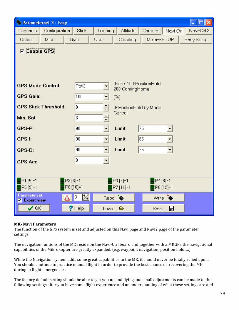
79
MK-‐ Navi Parameters The function of the GPS system is set and adjusted on this Navi page and Navi2 page of the parameter settings. The navigation funtions of the MK reside on the Navi-‐Ctrl board and together with a MKGPS the navigational capabilities of the Mikrokopter are greatly expanded. (e.g. waypoint navigation, position hold ,...) While the Navigation system adds some great capabilities to the MK, it should never be totally relied upon. You should continue to practice manual flight in order to provide the best chance of recovering the MK during in flight emergencies. The factory default setting should be able to get you up and flying and small adjustments can be made to the following settings after you have some flight experience and an understanding of what these settings are and

80
how they affect MK flight. Warning -‐ etting Changes Warning: These settings should never be made in flight and only made in small increments. Enable GPS (GPS active) Enables the GPS software functions to be selectable by switching or setpoints. (applies to both Navi-‐Ctrl tabs and Configuration tab. They are the same settings). GPS Mode Control This setting determines how you will control the primary GPS function of Position Hold. This option is usually set up with a poti assigned to a three way switch on the pilots transmitter. The switching sequence is: Off / Free, position hold (PH), Coming Home (CH).
Note: GPS Control Note: Remember-‐No matter what mode you are flying in, you will always have control of your MK with the sticks. Stick input will override GPS input.
• Off/Free is selected to disable the Position Hold and Coming Home features. • Position Hold (PH) enable the GPS system to assist in control of the MK in order to keep the craft in a single
GPS location. With the Dynamic Position Hold function described later and selected separately, the desired GPS location can be changed with movement of the control stick.
• Coming Home (CH) will direct the MK to return to the GPS location where the gyros were initially calibrated. These options can also be initiated using fixed values entered in the window:
• 0-‐99 means no GPS support (Free), • 100-‐199 Postion Hold (PH), • 200-‐250 Coming Home (CH).
Note: GPS Accuracy Note: Be aware that GPS Hold works very well, however, even in a finely tuned system it will wander around about +/-‐ 20 feet or so in any direction because of normal GPS error. GPS Gain This setting specifies how much influence the GPS has on the Flight Controller. The factory default is 100 with a range of 0-‐247. A value between 80-‐100 works well for most MK’s. If GPS-‐Gain is too high, the MK will over-‐correct and the position will swing.
Operating Note: Setting Changes Operating Note: when attempting to tweak the GPS settings, leave all the settings stock and play with the gain until it stops twitching. Make small adjustment, between 60 and 100. Than move to the other adjustments if necessary. GPS Stick Threshhold Here is you can set the threshold for GPS-‐Aid to log a new position. If you set it to 0 it's not set with the stick but only by turning the mode switch: In this case, you fly to the desired location and turn on PH. Then you can play with the stick and the MK will always be on the target position. If other values are entered, than the larger the number, the further the stick must be moved away from center to register a new point. It is the amount that you can move the sticks before it sets a new hold position.

81
Min. Sat The Minimal amount of satellites which must be received by the GPS in order to allow activation of the GPS functions (Sat-‐Fix). The more satellites that are received, the greater the GPS accuracy. For a 3D-‐Fix you must have a minimum of 4 satellites. It is recommended that you have a minimum of at least 6 for accurate GPS operation. Once this number of satellites is obtained, the GPS LED will start flashing. INFO: See the satellites in Kopter-‐Tool
If you "click" on the button -‐>MKGPS in the Koptertool you can see how many satellites (and how strong) you receive.
Don't do this during flight! Otherwise you can crash. GPS-‐P P-‐share of the control. Influence of distance on the GPS controller (Bigger = more roll when position deviation) Limit-‐ Limits the potency of the parameter GPS-‐P. If GPS-‐P isn't high enough, the MK will not tilt enough to correct a sudden drift. Tip: GPS-‐P in Theory GPS-‐P Imagine GPS-‐P like a virtual rubber band attached on one side to the MK and on the other side to the target position. It continually pulls the MK to the target position. the further the Kopter is away from the target point the stronger will be the pull. So, GPS-‐P determines the strength/thickness of the rubber band. If GPS-‐P is small, the rubber band is weak -‐ if GPS-‐P is high, the rubber band is stronger. If the rubber band is to strong the controller leads to swing. Limit (GPS-‐P) -‐ This parameter limits the pulling force of the "virtual" rubber band between the MK and the target position. With the increasing distance to the target and the rising proportional attractive force it would be too great beyond a certain distance. In reality the flight attitude of the MK causes the attraction to the target. If this flight attitude is getting to large the MK dips immediately. To prevent this situation is the reason for the P-‐Limit. GPS-‐I I-‐share of the control. Eliminates the permanent position deviation in the wind (larger = stronger tendency for prolonged position deviation). With regards to the rubber band example this parameter works like a memory. The longer the position deviation, the stronger the pull of the rubber band into the direction of the target. Limit Limits the potency of the parameter GPS-‐I. If GPS-‐I isn't high enough, the MK will not tilt (correct) enough during prolonged positional drift. This is the reason for the Limit.
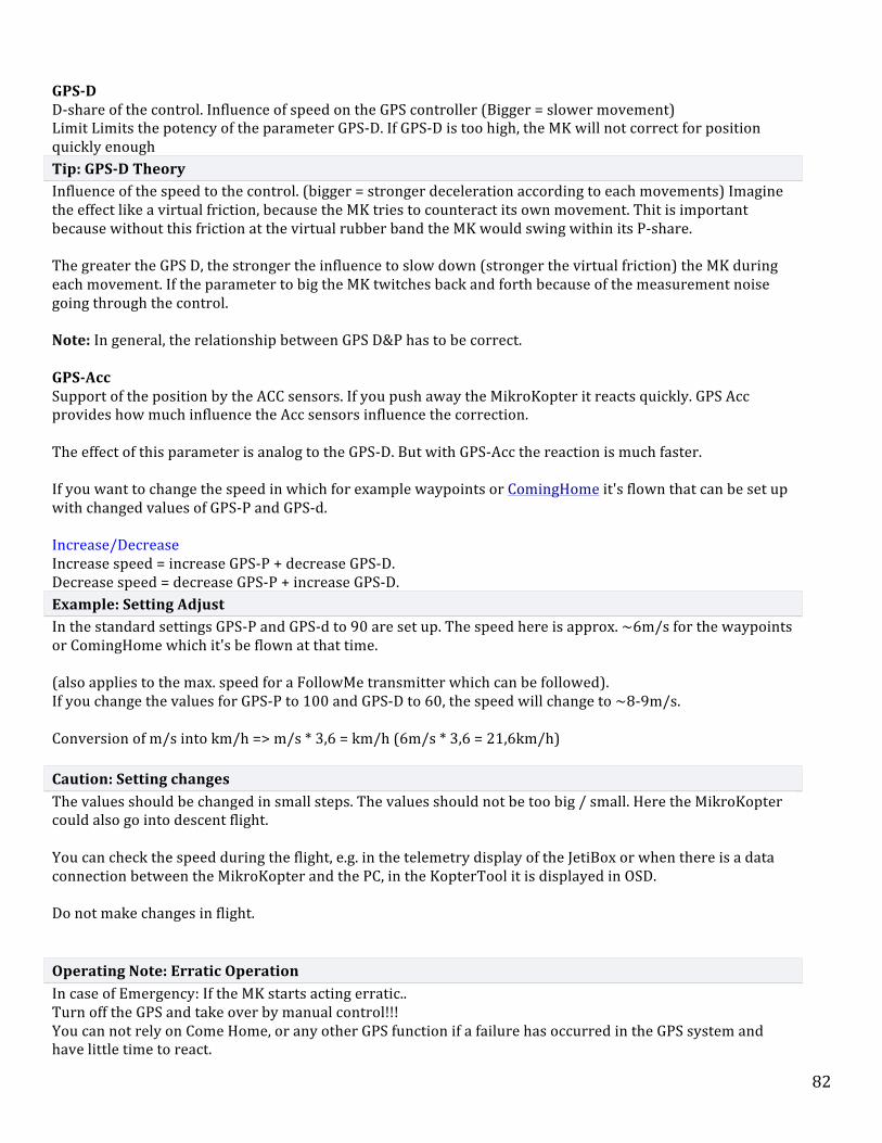
82
GPS-‐D D-‐share of the control. Influence of speed on the GPS controller (Bigger = slower movement) Limit Limits the potency of the parameter GPS-‐D. If GPS-‐D is too high, the MK will not correct for position quickly enough Tip: GPS-‐D Theory Influence of the speed to the control. (bigger = stronger deceleration according to each movements) Imagine the effect like a virtual friction, because the MK tries to counteract its own movement. Thit is important because without this friction at the virtual rubber band the MK would swing within its P-‐share. The greater the GPS D, the stronger the influence to slow down (stronger the virtual friction) the MK during each movement. If the parameter to big the MK twitches back and forth because of the measurement noise going through the control. Note: In general, the relationship between GPS D&P has to be correct. GPS-‐Acc Support of the position by the ACC sensors. If you push away the MikroKopter it reacts quickly. GPS Acc provides how much influence the Acc sensors influence the correction. The effect of this parameter is analog to the GPS-‐D. But with GPS-‐Acc the reaction is much faster. If you want to change the speed in which for example waypoints or ComingHome it's flown that can be set up with changed values of GPS-‐P and GPS-‐d. Increase/Decrease Increase speed = increase GPS-‐P + decrease GPS-‐D. Decrease speed = decrease GPS-‐P + increase GPS-‐D. Example: Setting Adjust In the standard settings GPS-‐P and GPS-‐d to 90 are set up. The speed here is approx. ~6m/s for the waypoints or ComingHome which it's be flown at that time. (also applies to the max. speed for a FollowMe transmitter which can be followed). If you change the values for GPS-‐P to 100 and GPS-‐D to 60, the speed will change to ~8-‐9m/s. Conversion of m/s into km/h => m/s * 3,6 = km/h (6m/s * 3,6 = 21,6km/h) Caution: Setting changes The values should be changed in small steps. The values should not be too big / small. Here the MikroKopter could also go into descent flight. You can check the speed during the flight, e.g. in the telemetry display of the JetiBox or when there is a data connection between the MikroKopter and the PC, in the KopterTool it is displayed in OSD. Do not make changes in flight.
Operating Note: Erratic Operation In case of Emergency: If the MK starts acting erratic.. Turn off the GPS and take over by manual control!!! You can not rely on Come Home, or any other GPS function if a failure has occurred in the GPS system and have little time to react.

83
Since GPS also influences Alt Hold, this must be turned off also. Practice flying without GPS often, practice turning off all of the automatic navigation and flying it back home. Don't fly out of sight unless your willing to risk total loss. Sometimes turning off the GPS and back on may clear the issue also.. Don't wait!! any time it seems to not do what you think it should turn it all off!! Some day, this practice may save loss of the aircraft and possible physical harm to someone.
Navi-‐Ctrl 2
The parameters of GPS wind correction, speed compensation, GPS max. Radius have no direct effect to the GPS-‐PID-‐controllers (P, I, D in the tab navigation Ctrl).

84
Choosing the functions
• Enable GPS o Unlock the GPS the software (for both Navi-‐Ctrl tabs). (has the same effect as the setting in Configuration) • GPS Wind correction o Attempts to correct for crosswinds by analyzing the current heading and comparing it to the target bearing
setting up a correction heading. This is done only from a reasonable distance to the target position.The setting % controls the strength of this compensation. A value of 0 means that the function is turned off.
• ACC Compensation
Sets how fast the MK will slow down in PositionHold-‐Mode before the position is locked after you have manually moved the sticks. The higher the value the quicker the MK will slow down after manual controlling and before it keeps the nominal position.
• GPS max. Radius This value, in meters, defines a circular area around the start position. Only inside of this circular area you able to set position targets (waypoints/POI). If a waypoint-‐position is outside of this area the target will be set on a spot of the edge of the circle which is close to the nominal position. The maximum radius is about 250m. That's equal to an area of approx. 500m in a diameter around the start position.
Note: Valid for Waypoint Flight Only Note: This parameter is only valid for the waypoint-‐flight! The function Position Hold and Coming Home are usable in full range of the transmitter/receiver.
• GPS Angle Limit o o Limits the maximum control influence of the GPS. A value of 100 is equal to an oblique position of 20°.
If the value too small it might be possible that the MK can't work against the wind and drifts away. If the value too high the approach to the target may be too fast.
• Position Hold Login Time o This is the maximum time after the MK logs the new position and after the sticks of pitch / roll axes are
back in neutral position. Yawing is possible without changing the set position. • Dynamic Position Hold o By switching on/off this function you can change the behavior of the MK in the function Position Hold.
Off: PositionHold (PH) switched on the movement of the Kopter will be directly controlled with the Nick-‐ / Roll stick. Here the function PH will be switched off if the sticks are moved. At the new position and after releasing the sticks the function Position Hold (PH) will be switched on again.
§
On: With PH switched on, you can manually fly the MK using Nick-‐/Roll stick to a new location while PH remains on. This feature moves the nominal values of the GPS coordinates rather than switching on and off PH. Therefore a more accurate positioning is possible during windy conditions. The Kopter flies slower to the positions.
§

85
§ Note: Dynamic PositionHold is switched on by default settings. • ComingHome Altitude o In the function ComingHome the MikroKopter comes automatically back to the start point (as far as a GPS-‐
Fix is available!). The MK can fly to the previously set up height. In addition the MK is 'parking' on the previously set up height while approaching the ComingHome coordinates. During the approach the previously set up height will be flown with 3m/sec. -‐ That's not possible to change! That means:
§ 0: OFF -‐> the actual height of the Kopter will be kept. 1-‐247: Value in meter -‐> this height will be flown directly with 3m/sec. after activating ComingHome (CH).
• Adjustable altitude for Coming Home In the settings you can set a fixed height for coming home (EasySetup or NaviControl2). With this function the Mikrokopter not only comes back... it also stays at a height of 25 meters for example. The climbing / descending speed is 3.0 meters per seconds -‐ you can't change this value
Note: Vario Altitude Only Note: The altitude will be used only in Vario-‐altitude-‐control. And only if the throttle-‐stick is in neutral-‐position.
• • Notice: The altitude will be used only in Vario-‐altitude-‐control. And only if the throttle-‐stick is in neutral-‐
position.
Dynamic Position Hold
• In PH-‐mode the GPS-‐target position will be changed by the stick movement. • So the MK will not log-‐off in PH-‐mode • That makes it much easier to fly during windy conditions because the MK can be moved more precisely • The direct stick-‐influence to the MK will be damped simultaneously.
Note: Defaul Setting Note: Default is ON. It can be disabled under "EasySetup" or "NaviControl2".
Stick
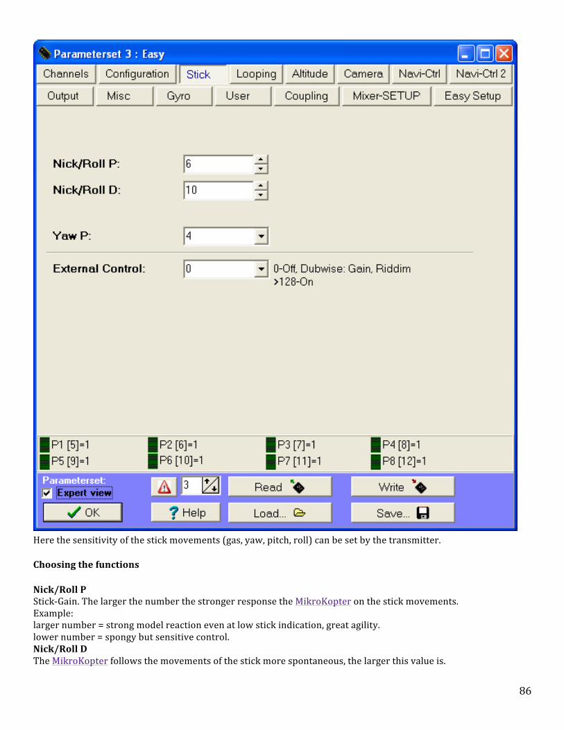
86
Here the sensitivity of the stick movements (gas, yaw, pitch, roll) can be set by the transmitter.
Choosing the functions
• Nick/Roll P o Stick-‐Gain. The larger the number the stronger response the MikroKopter on the stick movements.
Example: § larger number = strong model reaction even at low stick indication, great agility.
lower number = spongy but sensitive control. • Nick/Roll D o The MikroKopter follows the movements of the stick more spontaneous, the larger this value is.

87
Example: § larger number = severe, immediate model reaction, more "poisonous".
lower number = soft control. Strictly spoken, it affects the Stickspeed to the MikroKopter.
• Yaw-‐P (Gier-‐P) o Yaw rate ratio to stick deflection.
The value can be entered as a number or be placed on a potentiometer at the transmitter to change the behavior during the flight. Example:
§ larger number = fast rotation. lower number = sluggish reaction.
• External Control o This can be used also in addition to a transmitter to activate an external control.
This can be done for example via a mobile phone with the software Dubwise. To turn this feature on an arbitrary number that is greater than 128 has to be entered. Or a potentiometer is assigned to a switch at the transmitter. So the function can be switched on/off at the transmitter.
Output

88
A Switch-‐/Blink pattern at the transistor outputs (SV2 top port) of the FlightCtrl can be set here. This pattern can occur in a fixed time (0-‐247) or be controlled by a switch / potentiometer on the transmitter.
As an additional option it is to be set whether this pattern will always be active, or only after the start of the engines. If the option "Only active after engine start" (just after the start of the motors active)is chosen a green switch box
appears behind the bit mask setting. Here the initial condition for stationary engines are fixed.
If the green switch box is clicked the green LEDs lit steadily before you start the engines. After turning the motor on the LED will flash at the set pattern.
If the green switch box is off the LED do not lit prior to the start of the engines. After turning the motor on the LED will
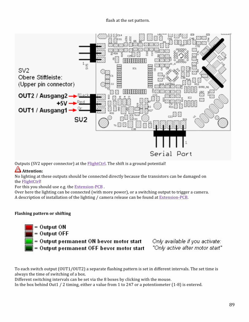
89
flash at the set pattern.
Outputs (SV2 upper connector) at the FlightCtrl. The shift is a ground potential!
• Attention: o No lighting at these outputs should be connected directly because the transistors can be damaged on
the FlightCtrl! For this you should use e.g. the Extension-‐PCB . Over here the lighting can be connected (with more power), or a switching output to trigger a camera. A description of installation of the lighting / camera release can be found at Extension-‐PCB.
Flashing pattern or shifting
To each switch output (OUT1/OUT2) a separate flashing pattern is set in different intervals. The set time is always the time of switching of a box. Different switching intervals can be set via the 8 boxes by clicking with the mouse. In the box behind Out1 / 2 timing, either a value from 1 to 247 or a potentiometer (1-‐8) is entered.

90
Example with a fixed value
• In the upper picture the first box is clicked for Out1 bitmask and the remaining 7 are not. As time is to Out1 timing a 20 registered. The number that is entered is multiplied each x10 [in 10ms]. This would then in 20 x 10ms 200ms switching time for each box One cycle (8x200ms) would take a total of 1600ms (1.6 seconds) until the switching process starts all over again. Is now for example an illumination connected it's like 200ms on, 1400ms off, 200ms on, 1400ms off, and so on.
Example with a potentiometer
• If a potentiometer (1-‐8) instead of a fixed value (See Channels) is entered, there are three possibilities. Use of a switch, button or potentiometer on the transmitter. :
1. Switch of the LED: § A switch on the transmitter can switch on or off the lighting. It does not matter whether a flashing pattern is set.
An adjusted flashing pattern has no function here. 2. Button to trigger a camera: § At the switch output for example the Shuttercable can be connected. With the button then the switch output
is closed or opened for the duration of the operation. If the first of the eight boxes is checked (the rest is off) while operating the switch, the switching contact is closed.
§ However, if the second of the eight boxes is selected, pressing the button of the switch the contact opens. 3. Poti to shift the LED: § With a potentiometer on the transmitter the value of 1 -‐ 247 is set. So if the pot will be adjusted at the transmitter
the adjusted value of each pot is shown § as a number (time x 10ms) and the set accepted by flashing sequence runs faster or slower. This depends on the
rotation of the potentiometer.
Warning function
Both outputs can adjust the flash pattern with lower voltage / reception failure / I2C errors, so that even one example optically displays a lower voltage or a reception failure.
It's flashing if there is:
• Under voltageUnterspannung • I2C-‐Error • loss of the receive
If an output is used to trigger a camera for this output, the warning feature should be off. Otherwise the camera would trigger when a warning is in this interval.
User

91
This configuration parameter found in the official version of the Flight Software / NaviCtrl not apply. Here, no changes can be made. Therefore, all settings are left at 0.
The User parameters facilitate the handover to the MikroKopter for testing, special or debug versions.
Section 4 -‐ Flight Control Modes
Contents 1. Introduction 1.1 MK-‐Flight Control Modes 2. Altitude Control 2.1 Altitude Ceiling 2.2 Vario Altitude 3. GPS Functions 3.1 GPS_MODE_FREE 3.2 GPS_MODE_AID -‐ Position Hold (PH) 3.2.1 option -‐ Dynamic Position Hold 4. Care Free 4.1 Care-‐Free (Teachable) 4.2 Teachable CareFree as example 4.3 Video of the CareFree feature 5. GPS_MODE_HOME -‐ (Coming Home CH)

92
5.1 Option -‐ Adjustable altitude for Coming Home 5.1.1 Option -‐ Coming Home as Fail Safe 6. Example: 7. Exercises
Introduction
MK-‐Flight Control Modes
There are two altitude control mode options (altitude-‐ceiling and altitude-‐vario) that can be selected from within the MKTool software. Once one of these options are enabled the option is than initiated with the operation of a single switch on the control transmitter. The altitude function is typically activated along with a GPS function. There are also two primary GPS control modes (Position Hold-‐PH, and Come Home-‐CH) that are enabled from within the MK-‐Tool software. The enabled options are then typically activated by the use of a single 3-‐position switch on the transmitter (Off/PH/CH).
Note: Dynamic Position Hold Note: The "Dynamic Position Hold" option is selectable from within the MK-‐Tool software and actived along with the Altitude-‐Vario function. Dynamic Position Hold allows repositioning the MK without operating the PH switch. This is a new feature that is very helpful especially in windy conditions. These modes make the MK much easier to fly and enables the pilot to take his concentration away from flying and focus on camera operation, the MK telemetry, and other tasks for short periods of time while the MK is in-‐flight. It is the understanding and proper operation of these control modes that really makes the MK a usable tool for aerial operations. The following descriptions are an expanded discussion of the MK flight control modes.
• Altitude -‐ Typically activated by a single transmitter switch. o Fixed Ceiling -‐ MK likes into current altitude when switch selected o Vario • GPS -‐ Typically all three of these are switched with one three-‐position switch on the controller transmitter. o Free o Aid o Coming Home • Care Free -‐ Typically activated by a single transmitter switch.
Tip:Learning the modes Note: It is important to practice flying the Mikrokopter often without these modes switched on in order to maintain the skills necessary to retrieve the little bird, if the navigation system fails. It is highly recommended to start with it in Free Mode, get the GPS fix and then start the motors and fly and hover for a few seconds just to make sure the MK is trimmed, and set OK before you start using the automated controls. If the MK is not hovering correctly the GPS will have difficulty trying to hold it in place. It is a good practice to make sure the MK is working correctly so if you have to switch off the automated control, you will have a manually controllable MK.
Warning -‐ GPS Lock
93
Warning: To operate in GPS modes, other than OFF, the green LED on the GPS must be flashing to indicate that a FIX has been achieved. A fix may take several minutes, especially prior to the first flight or in a sheltered area where the GPS does not see the sky clearly. If a fix is not obtained, the MK does not know where it is and there may be unexpected flight characteristics, including loss of the aircraft. Make sure even if the green GPS light is flashing you wait until you hear the beep. The flashing may start with as few as 3 sat's locked but you need 6 or what ever your setting is set to for full lock then you get the beep.. if you try and put position hold on without sat lock it will beep over and over at you.
Altitude Control While the altitude control function relies on the altimeter device rather than the navigation board, it plays an important role in overall operation.
Altitude Ceiling
When this mode is switched on, the current altitude is set as the new ceiling and the MK software limits throttle input greater than the amount needed to maintain the setpoint. Additional increases in throttle input will force the MK higher, however it will return to the original setpoint when gas is reduced. Also, since this is a ceiling, any reduction in throttle below that needed to maintain altitude will lower the MK. The reference setpoint can be specified in several ways. E.g. you can put the set point to a fixed value that would never exceed. Alternatively, the setpoint can be a potentiometer (1 to 8) to assign and change the channel assigned to the value of the transmitter during the flight. Another possibility is to activate the checkbox use switch for setpoint (switch for height) at which the set point should also be assigned to a potentiometer, so you turn on the channel associated with the transmitter over a switch, and the height control can simultaneously take the current height value as a reference. This is the most common method.
Note: Altitude Control Note: Generally the GPS will only work well when the altitude control is active. Otherwise the vertical accelerations brought by with the control movements will confuse the Acc-‐Sensors to much. With a correctly attached NaviCtrl, the FlightCtrl will now beep more often when either GPS_MODE_AID or GPS_MODE_HOME are selected. The tones communicate the following: beeping every 1 second *Beeep* -‐ Until a minimum of 6 satellites has been found. It will become quieter when a FIX has been obtained but not yet 6 satellites found. Fast 5khz Beeping *Drrrr* -‐ The MK is leaving its target coordinates by more than 15m (Also happens when the mode is switched to Coming home and the MK distances itself by 15m from target) 1x Beep *Beeep* -‐ Logging of new target coordinates (about 2 second delay) In alt-‐hold you have a limited altitude range at your disposal, when you flip the switch (Never start with any altitude control, or it will get bumpy) If you want to go higher, you have to reset the switch, which will often lead to fast accent since you are already pushing your thrust-‐stick up.
Vario Altitude
When Vario altitude is selected in the software and activated with the assigned altitude switch, the height control takes full control of the overall thrust. You can not control it directly through the throttle stick on the transmitter. Rather serves to active height control over the gas stick to change the setpoint and nominal values. There are neutral points of the gas sticks, the parameters of the Stick neutral point can be fixed. If the parameter Stick neutral point is equal to zero, is used as a neutral point of the gas stick position at

94
which the thrust exactly compensates the gravitational force (Hoverpoint). If the gas stick is above the neutral point, then the nominal value of the level moves up -‐ if the gas stick is below the neutral point, the reference is shifted downwards. The speed with which you moves the setpoint, the gas is proportional to the stick position. The option Acoustic Vario (acoustic variometer) is very helpful and signals the changing altitude with an audible tone.
GPS Functions
GPS_MODE_FREE
(off) This mode is free flight.
GPS_MODE_AID -‐ Position Hold (PH)
(GPS_Mode_Control between 20 and 200) GPS has a supportive effect The GPS-‐speed complements the pilots commands and where applicable acts with a slowing/braking effect. When no elevator or roll controls are given by the pilot, the MK will hold its current position. The new position will be logged when the MK falls below a certain speed or after no more than 4 seconds. A beep will indicate the logging of a new position. Note: PH does not control altitude, it only limits horizontal movement. Altitude limits (ceiling) are initiated only when the Altitude Hold switch is activated. So, essentially, once PH is activated the GPS picks a point and stays in a circle around that point. The point can be changed by stick movement, but, once it slows, it begins to hold the new point. if the throttle is decreased, the MK will settle at that point.
option -‐ Dynamic Position Hold
This function works almost the same as the normal Position Hold however, if selected, it does not have to log off and reset its location. This makes for easier and smoother operation.
• In PH-‐mode the GPS-‐target position will be changed by stick movement. • So the MK will not log off in PH-‐mode • That makes it much easier to fly in windy conditions, because the MK can be moved more precisely • The direct stick-‐influence to the MK will be damped simultaneously.
Care Free In this mode, the control direction of Nick and Roll is not made by "Front" definition, but by the direction in which the front of the MK is positioned when the engines are started. In this mode you can yaw the MK without it having any co-‐rotation effect on Nick and Roll. This is a very useful mode when the MK will be operated in front of you, especially at a distance where the
95
actual front (red arm) is difficult to distinguish. It also makes directional photography much easier as the nose/camera position can be easily directed without regard to MK flight direction. Tips: You must first get used to the fact that the front arm is irrelevant For safety you should practice in an open area and use GPS-‐CH to get back. The compass must be properly calibrated to work well and safely See Video-‐-‐http://www.vimeo.com/13726420 Warning-‐-‐ Pilot direction change! Warning: The pilot should never change his physical orientation while the MK is in flight. Remember, in this mode, the red arm is no longer the front and all control direction is performed relative to the position that the nose was in at start up. If the MK gets behind you in Care Free Mode, all control action becomes reversed and it is very difficult to re-‐orientate yourself to flight. Also, Looping will not work with Carefree and this feature requires a Navi Ctrl with a Compass
Care-‐Free (Teachable)
"Techable" means, that the control direction can be changed during flight So, the control direction will be "teached" each time, the assigned CareFree-‐Switch is switched on. A distinction is made:
1. Within 20m of the starting point, the front-‐direction of the MKs will become the control-‐direction 2. Outside of the 20m, the bearing between home and MK-‐Position will become the control direction
So the pilot can now rotate on the spot, because he can teach-‐in a new CafreFree-‐direction by using the switch. Outside the 20m he does not even have to see where the front-‐direction was at the time.
Tip: If the pilot has the MK well in sight, he should turn the MK so, that the nose points directly away from him. Then it does not matter if the MK is inside or outside the 20m -‐ the control direction would be the same in in both cases anyway.
the operation of CareFree 2.0 is more intuitive than you think Example 1:
• In case that the MK is too far away and the Pilot does not know its actual direction, he would have problems controlling the MK manually
• Now the CareFree-‐Switch could be switched on and the Pilot would simply fly as if the nose would point away from him Example 2:
• The pilot stands at a building that he wants to photograph • He would use CareFree and turn the MK 180° in his direction • If he wants to take photos from the other side of that building, he could re-‐activate CareFree on the other
side of that building and turn again 180° into his direction Note: This function is implemented since Version 0.86
Teachable CareFree as example
The arrow on the MK shows the control direction in these pictures

96
1. Direction of the MK before activating the CareFree switch 2. CareFree is switched on -‐> the actual direction will become the control-‐direction 3. Even if the MK is turned, the control direction will remain equal
1. Direction of the MK before activating the CareFree switch

97
2. CareFree is switched on -‐> the actual bearing between MK and pilot will become the control-‐direction -‐ no matter of the actual MK-‐Direction
3. Even if the MK is moved and turned, the control direction will remain equal
The pilot wants to teach-‐in a new CareFree direction, even If doen't know the actual direction of the MK
1. CareFree was already on, but the control direction is inconvenient 2. If the Pilot switches CareFree off, the actual direction will become the control direction 3. CareFree is switched on -‐> the actual bearing between MK and pilot will become the control-‐direction -‐ no
matter of the actual MK-‐Direction
Video of the CareFree feature
Caution: Come Home Overflight Caution: It is common and useful to use GPS-‐Come Home mode when operating in Care-‐Free mode in order the bring the MK back to you regardless of it orientation. However, you must be aware that in CH mode, the MK may slightly overfly home and enter a region where operation becomes confusing. In this case, use CH to get the MK close enough to see the actual front (red arm), than select Position Hold, rotate the front to nose out, deselect Car Free, and continue home under manual control.
GPS_MODE_HOME -‐ (Coming Home CH) (GPS_Mode_Control > 200) Coming Home -‐-‐> Fly back to originating position. The position during the start of the motors is logged as Home. Note: CH only works if you have GPS fix BEFORE the motor starts. Warning: When Coming Home is used to fly back to yourself, the altitude control must be active otherwise it will drop down and may continue to accelerate down. Warning: Make sure you have extra room around the Home Position as the MK may overfly the location slightly as arrives home.
Option -‐ Adjustable altitude for Coming Home
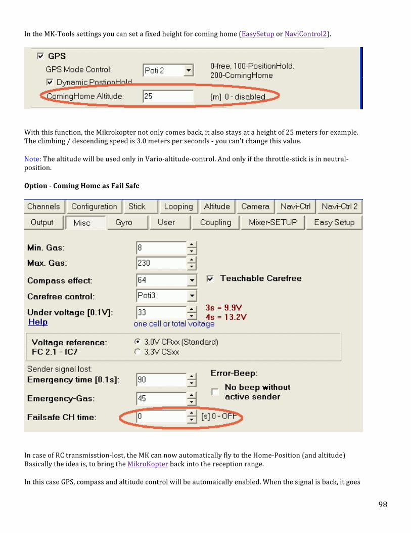
98
In the MK-‐Tools settings you can set a fixed height for coming home (EasySetup or NaviControl2).
With this function, the Mikrokopter not only comes back, it also stays at a height of 25 meters for example. The climbing / descending speed is 3.0 meters per seconds -‐ you can't change this value.
Note: The altitude will be used only in Vario-‐altitude-‐control. And only if the throttle-‐stick is in neutral-‐position.
Option -‐ Coming Home as Fail Safe
In case of RC transmisstion-‐lost, the MK can now automatically fly to the Home-‐Position (and altitude) Basically the idea is, to bring the MikroKopter back into the reception range.
• In this case GPS, compass and altitude control will be automaically enabled. When the signal is back, it goes
99
back to 'Manual Control' • After the set time, the MK uses "Emergency Gas" and the "Emergency Time" to perform a descending • The time is limited to 30 seconds, this is enough to go through short rc signal lost times and put
theMikroKopter nearer to the starting point • The MK will do this for the preset time (no matter if it reached home or not). • Waypoints are cancelled until the reception is back • The MK is flying a direct route towards the home position • If a "Coming Home Altitude" is set, this will be used immideately with a sink/rise-‐speed of 3.0m/sek • When signal is back, the MK will not go back to the old Position or altitude automatically
Note: By default, the CH-‐Time is to 0sec, that means it is disabled by default. It can be set under "MISC" (expert setting).
Example:
• MK is in 120 distance and 50m altitude. • FailSafe-‐Time is 30sek and Emergency-‐gas-‐time is 15sek. • CH-‐Altitude would be 20m
So in the example the MK would:
• fly back and descend simultainusly • altitude would be reached in second 10 after Transmitter fails • position would be reached in second 20 • there it would wait for a while, because the FS-‐Time is 30 seconds • Emergency gas would be used in second 30 and the MK comes down • the motors would be stopped in second 45
Caution: Before using this function the user have to clarify whether such a mode acceptable to the particular place or not of a legal, actuarial or other provisions is permitted. When the distance from the target point is exceeded by 15m, a quick beep of 5 times per second (5Hz) will sound.
Exercises Exercise Navi 1-‐ Altitude Hold Take off and fly up to 25 feet, switch on Altitude Hold (AH) and fly a small box pattern for one minute. Swlitch off Altitude Hold (AH) and climb 10 more feet then reengage Altitude Hold (AH). Continue to maneuver in a small area repeating the same operation until you feel confident with this operation. Repeat this exercise until you become comfortable with this maneuver. Exercise Navi 2 -‐ Altitude Hold/Position Hold Take off and fly up to 15 feet and out about 30 feet. At this point select Position Hold (PH). Now climb 10 feet and select Altitude Hold (AH). While in this location, yaw the MK 360 degrees. Once complete, throttle back and descend 10 feet, switch the Altitude Hold (AH) switch off and on to remain at the new altitude. Release Position Hold (PH) and fly the MK 30 feet further out and perform the same operation. Once complete, switch off Position Hold (PH) and return home. Repeat this exercise until you become comfortable with this maneuver. Exercise Navi 3 -‐ Altitude Hold/Position Hold/Come Home Take off, climb to 30 feet and fly out 30 feet, select Position Hold (PH) and climb 20 more feet then select Altitude Hold (AH). Release Position Hold (PH) and fly 50 feet further out and reselect Position Hold (PH). Do a slow 360 degree turn and stop wi the nose pointed away from you. Release Position Hold (PH) and Select Come Home (CH). The MK will proceed the the location of motor start and hover above that location.

100
Give yourself a good 10-‐15 feet of space and reduce the throttle to lower and land the MK within about 10 feet or so of it’s takoff point. Repeat this exercise until you become comfortable with this maneuver. Exercise Navi 4 -‐ Altitude Hold/Position Hold/Care Free Take off, climb to 50 feet and select Altitude Hold (AH), fly out to a distance of 50 feet and select Position Hold (PH). Now select Care Free (CF). Deselect Position Hold (PH) and turn so that the nose is 90 degrees off from where it was, now do a box pattern with the nose pointed in the same direction. for all four turns. Proceed to yaw the MK while doing shallow turns. Fly the MK home and land while still in Care Free (CF) mode making sure you do not overshoot home getting the MK behind you. Repeat this exercise until you become comfortable with this maneuver.

101
Section 5 -‐ Sensor Calibration
Contents
1 Sensor Calibration 1.1 Accelerometer (ACC) Calibration 1.1.1 What needs to be level? 1.1.2 Gyroscope (Gyro) Calibration 1.2 Stick Position Calibration Chart 1.3 Test of sensor values in MK-‐Tool 2 MK Compass Calibration 2.1 Watch these videos for demonstration of the method.
Sensor Calibration
The MK is equipped with some of the most modern and sophisticate flight control sensors available, however, if these sensors are not calibrated correctly and accurately, the MK Flight Control Computer will have less than ideal input data to work with and correspondingly poor performance. It is well worth your while to understand and apply the proper calibration procedures. The MK should require very small inputs on lift off (about 1m from the ground) to hold in a steady hover. If you are trying to control the MK with large stick movements then you should look at how the MK is set up. The MK will always try to maintain the position it has at the moment of calibration because it accepts that position as level. After the initial ACC calibration is accomplished and properly saved, this same "level" reference is loaded into the MK Flight control as the true level plane when power is applied. That means, the more it is out-‐of-‐level, the more correction will be needed by the pilot to maintain position. While performing the calibration, the actual "Setting" (amount of beeps represents the setting-‐number) can be chosen.
Accelerometer (ACC) Calibration
Your initial ACC calibration is critical to MK performance. It basically teaches the FC what is level as well as setting the accelerometers. If this calibration is not done correctly the MK will perform poorly. Note: Calibration of the ACC's only needs to be done once or if you have control issues or a software update. The following procedure is a method that I have learned from others and will ensure proper ACC Calibration. There are certainly other methods that will be less time consuming and once you understand what is being accomplished by calibration, you my very well decide on your own method.
What needs to be level?
Since it is the propellers that provide thrust to make the MK fly, it is important that the motors and support arms are all on the same plane. (level with each other). If this is accomplished by ensuring the arms are level with each other and the motor shaft are vertical, then the Flight Control computer and the pilot will have less corrections to make and thus the MK will fly level and smooth. The following calibration procedure will check to make sure the support arms are level with each other as well as calibrate the ACC. Setup: Note: Once again, This process is just the way I set up my calibration, feel free to make changes to this method in order to adjust to your own circumstances.

102
Selected a table that has adjustable screw type foot pads (if possible) on the bottom in order to make leveling easy. Use playing card or other objects placed under the table legs if the table does not screw type level pads. If the table top has more than one piece, place a firm piece of plywood on the top of the table so that it will a have single surface to level. Use a bubble level in the center of the table, adjust the table legs until the bubble level is exactly level while looking straight down on it. I went to the local hardware store a purchased eight pieces of threaded 12 in. x 3/4 in. plastic pipe, eight metal floor flanges, and eight 3/4 in plastic pipe caps. I than pieced together eight stanchions that the arms of the Okto rest on. These stanchions are heavy enough to be moved around on the table top as needed to fit the Okto frame. I found that there is no need to screw down the bases as the metal is heavy enough to keep them from sliding. The threaded caps are adjusted so each stanchion is exactly the same height. See the picture below:
Arm Straightness Check Once the stanchions are in place, carefully lower each arm of the MK onto the stanchions while at the same time checking to make sure the arms are not bent. Make sure the MK is resting squarely on the stanchion and not the LEDs/cable ties. Hint: If you find one arm touching a stanchion before the others, make sure the centerpiece bolts are secure. Unless you have had a crash, it is unusual for a boom to be bent. If you visually see a bend, gently bend the arm into position by applying pressure where needed. If the arm is not square with the others, use an open end wrench to twist each arm slightly to bring it back to where it should be to be square and on the same plane. Also, there is a natural flex in the aluminum tube and a slight degree of error, less than 2 or 3 mm, is acceptable. Calibration procedure:
1. Remove everything but the basic MK and landing gear. 2. Make sure you are using setting 3 (Easy) as this makes normal flying easier. 3. Turn on the MK/TX and plug it into the MK-‐tool. 4. In MK-‐Tools -‐ go to the no.3 lcd screen. (green led type readout with number 3 upper right hand corner) 5. Make sure the main trims on your TX are in the center or zero. 6. Go to your sub-‐trim menu in your TX and get K2/roll and K3/nick values to zero. 7. Now for the actual calibration. Move the left stick (Throttle/Yaw) to the upper right corner and hold until the MK

103
beeps. This value is stored in EEPROM and only needs to be done once, after that, every time you turn on the MK, the ACC settings are automatically loaded from the EEPROM.
8. Test fly the MK in a no wind situation with no gps hold.You should be able to hold a hover and trim in the direction you are holding the stick so you can then let the stick go and the MK will remain in the same place. The MK should stay pretty much in one spot unless it gets some wind or some stick. Note: The leveling control starts working from a certain throttle value only. If, after this, the MK still veers off to one side, double check arm and motor straightness, and weight distribution.
Gyroscope (Gyro) Calibration
The micro gyros on the MK are very temperature sensitive and this calibration must be done every flight in order to stabilize gyro temperatures in preparation for flight. This calibration is necessary because the sensors have a series of scattering and temperature dependence (also the resting values of individual axes of the acceleration sensor are different). Procedure: 1. Place the MK on a stable surface an do not move it. note: the MK does not have to necessarily be perfectly level as the Flight Controller will be using the stored "level" reference made at the time of ACC calibration. 2. After applying power move the throttle up and to the left until the buzzer beeps and the green LED goes out. (Thenumber of beeps corresponds to the setting number.) Remember: only the gyros, are calibrated in this procedure, this does not set level as with the ACC calibration. This process also powers up other components of the Flight Control board and prepares it for motor start. -‐-‐-‐-‐-‐-‐-‐-‐-‐-‐-‐-‐-‐-‐-‐-‐-‐-‐-‐-‐-‐-‐-‐-‐-‐-‐-‐-‐-‐-‐-‐-‐-‐-‐-‐-‐-‐-‐-‐-‐-‐-‐-‐-‐-‐-‐-‐-‐-‐-‐-‐-‐-‐-‐-‐-‐-‐-‐-‐-‐-‐-‐-‐-‐-‐-‐-‐-‐-‐-‐-‐-‐-‐-‐-‐-‐-‐-‐-‐-‐-‐-‐-‐-‐-‐-‐-‐-‐-‐-‐-‐-‐
Stick Position Calibration Chart The image below shows greater detail of how the sticks are used to select settings and calibration modes: Explanation: NickRoll joystick Left Centre = Setting1; Left Up=Setting2, Centre UP=Setting3, etc. Again: keep the throttle-‐yaw joystick upper left and the Nick-‐Roll joystick at the same time to any of the positions mentioned above. It also works the other way around, first choose the setting with Nick-‐Roll, keep the joystick there and calibrate with throttle-‐yaw.

104
Test of sensor values in MK-‐Tool When the controller has been successfully programmed, you can check the sensor values with the MikroKopter tool. For this procedure you connect the serial converter with the large ribbon cable. The MK (or flight control board if your testing the board only) must be put in a horizontal position and switched on, then start the scope option in the MikroKopter tool (if the scope was already running you should stop it for a moment to reset the zoom range). We observe here only the first five analog values. The other analog values can be switched off via the tab "Scope“ in the MikroKopter tool if the display becomes to difficult to read. Now you tilt the board as smoothly as possible to about 45 degrees in direction of the pitch axis. On the scope you check the signal values. The signal of the pitch integral and the pitch acceleration sensor (here red and yellow) should show a significant value. It is important that the overlaid graphs are identical as far as possible.The same check has to be made on the roll axis (here blue and green):

105
Then we check the yaw gyro. For this purpose we turn the board around the yaw axis and observe the signal of the gyro. As long as we turn the board there will be a value > 0 which will come back to zero when we stop moving the board. We check the offset values of the gyros in the virtual display (the values in parenthesis): For this purpose we click through the buttons in the corresponding menu. The offset values should be around 500 (+-‐100). In this example the yaw gyro has a problem (178). It must be recalibrated or changed. Test of the Rx signal In the virtual display we can read the R/C values: With the R/C control we can adjust the values in the range of ca. -‐120 to +120.
MK Compass Calibration These instructions are intended to guide you through proper compass calibration of the MK-‐Mikrokopter series of multi-‐rotor RC aircraft. The MK must have the proper navigation hardware and software installed. Additional instructions and video are available on the mikrokopter.com website. MK-‐Axis Reference Graph (diag. 1) -‐ The diagram below shows the different MK Axis Lines used in this procedure.

106
Operating Note: Calibration Important Notes:
• When first operated, the MK3Mag needs to be correctly calibrated! Otherwise the NaviBoard will show you "Err:6 bad compass value".
• Since Version FC:0.84 it is much easier to calibrate the compass with a "clicking sound". This method has the advantage that you doesn't have to hold the Kopter "perfect" horizontally.
• The Nick-‐ and Roll axis refers to the FlightCtrl, and not on the Mixer you use! The arrow of the FlightCtrl shows the Nick axis!
• Calibration should be accomplished outside, away from magnetic influences! • Do not calibrate the MK directly next to a house, near power poles or metallic / magnetic surfaces. • Take your cell etc. out of your pocket.
Calibration Procedure
1. Start Calibration -‐ Initiate Compass Calibration by holding the transmitter nick/right stick straight-‐down and moving the throttle/left stick up-‐and-‐left, you will hear one beep. Compass calibration has now begun.
2. Calibrate Nick Axis -‐ Hold the MK with the front arm pointing north or south (use a compass or GPS to determine the proper direction, get as close a you can, but, it doesn’t have to be exact). Now, move the transmitter nick/right stick to the bottom, you will hear two beeps, step 2 of the calibration has begun when the clicking sound starts with each move of the MK. Rotate the MK in the north-‐south direction so that the hub of the MK rotation is along the nick axis on diagram 1. The MK is now finding new points of maximum or minimum values. When the beeping stops, the Nick axis is calibrated.
3. Calibrate Roll Axis -‐ Point the MK so that the nose is facing east or west than roll the MK a few times in the direction of the MK roll axis (diagram 1) so that the rotation axis or hub is around the X axis as shown on diagram 2. The rotation is still north/south. Rotate until the buzzer stops beeping than move the nick/right stick to the bottom. You will hear three beeps that signal the end of the nick/roll calibration process.

107
4. Calibrate Yaw (Z) Axis -‐ With the nose still facing east, move the nick/right stick down, you will hear four beeps that signals the start of Z Axis calibration. rotate the MK a few times around the roll axis as indicated on diagram 1 (X axis on diagram 2). Rotation will remain in north/south orientation until the buzzer stops beeping.
5. End Calibration -‐ Pull the Nick stick down -‐ you will hear one calibration beep that signals the exit of the calibration process. If the calibration fails (compass still reports "invalid compass value"), you can take a look here: MagnetError The process also works in older firmware versions, but then without the clicking sound

108
Watch these videos for demonstration of the method.

109
Section 6 -‐ Weight and Balance
Contents
1 Weight and Balance 1.1 Center of Gravity 1.2 Other Vibration Correction
Weight and Balance
Center of Gravity
While we have been discussing sensor calibration, there is another important factor that goes along with this study called Center of Gravity.
Although we have taken precise steps to make sure the MK knows where level is, the load that the craft will be carrying -‐ cameras, batteries, camera mount, FPV transmitter, etc., must all be added very carefully so that our own actions do not throw the MK out of balance. Add additional payload one piece at a time, so that you can determine which component, when added, throws off CG and make the appropriate load shifts. Normally, the MK will counter small balance variations very well. As mentioned previously, if the MK is out of balance some motors are going to have to work harder than others, in addition you will have less authority in a given axis due to the fact that the motor is already putting out more power than should be required for given task, similar to having a twisted motor .. (already using certain amount of yaw to compensate) will have more yaw authority in one direction than the other. Balance is very important if you are trying to build in some level of fail-‐safe. If the craft is out of balance, possible failure could be on heavy portion of MK .. and as such will have substantially more difficulty maintaining stability. A quick check to verify that the center of gravity is good is by lifting up the MK under opposite arms with ink pens/pencils (use as a pivot point) and use your battery to get the CG right. In my case I used two of the stanchions that I built for the ACC calibration to balance the MK and check the CG. Center of Gravity Flight Test If you have a ZigXbee you can select the FC in the MKtool during flight then hit the 3D button and you will get the Balance tool graph. This is a great way to test the Center of Gravity position. The red dot points to the center of gravity and should be close to center. Since your Lipo is the heaviest item on the MK, move it or other stuff around to move the dot in the center. Note: Check the ACC setting on the Balance screen in the MK tools it should show a green rectangle in the center of the screen a red one and it is not calibrated correctly.
Other Vibration Correction
While MK's with larger motors tend to create additional vibration, the following simple checks can be taken to eliminate vibration sources that may crop up even in the standards MK's.
• Balance your Props • Glue down your Caps, on BL's FC, Navi, anyplace that has a standing or bent over CAP. Glue them with Goop

110
or silicon or hot glue..something non conductive. • Glue down your Altitude Sensor to your FC. After the heat shrink and foam. • make sure your FC is free to move on the vibration Dampeners. No cables rubbing no lipo cables touching. • Make sure your Motor wires are not rubbing on the Frame ring or Power Dist boards. Check them for
chaffing.

111
Section 7 -‐ Supplements Supplements This section contains additional information that may be helpful in building, maintaining and operating the Mikrokopter. MK-‐Manual Supplements
112
Section 8 -‐ Safety Information A Mikrokopter is not a toy. These safety instructions are intended not only for the protection of the aircraft, but also to protect your own safety or others. Improper operation can cause serious injury and property damage. As with any machine, there is no guarantee of error-‐free behavior of the electronics or software. Operation of any MK requires careful preparation and review. It is important to operate the MK wisely, both in the air and on the ground. It is your responsibility make sure both you and the MK are fully capable of the intended task.
Overflight Warning: Do not fly over people! You may also need appropriate insurance before flight, as required by law in many countries!
General
• A Mikrokopter is not a toy and not suitable for children under 14 years. • If you don’t have sufficient knowledge about the control of the MK, please contact someone with experience. • An appropriate (model aircraft) liability insurance is required. In general, model aircraft are not covered by
a standard liability insurance. • Refer to the Wiki and forum about the features and operation of the Mikrokopter.com.
Before starting
• Check the reliability of the Mikrokopter. • The flight battery and transmitter battery must be fully charged. • Always turn on the transmitter first and then the MK, this allows for proper two-‐way communication to
lock in. • Watch for visible damage such as loose screws, broken, unbalanced or damaged propellers, faulty
connectors or solder joints, broken pipes, etc. • All propellers must be in a good condition and securely mounted. The motors must spin smoothly. Please
ensure that there are no objects in the rotational plane of the propellers or within a distance that poses a risk of obstruction. Rotating propeller ends are dangerous to touch – never touch a rotating propeller with fingers or other body parts.
• Ensure that the selected channel on the remote control is free and that you’re within range of the transmitter.
• Ensure the sensors are calibrated (when the motors are off move yaw and gas stick into upper left corner until it beeps) and that you hear the appropriate audible beep count.
• Different settings can result in fundamentally different flight characteristics and occupation of the Channel functions. Make sure that you are familiar with the setting and its features.
• After starting the motors, check that all motors are running and rotate evenly. Please fly carefully at a low altitude until you know that everything is working fine.
• Perform a pre-‐flight check (see checklist below). • Start manually – switch off altitude control and GPS. • The electronics must not be wet and should be operated in the temperature range of 0-‐40 °C
During the flight
• Do not take risks! Your own safety and that of your environment depend on the good behavior of the pilot. Always maintain a safe distance from people, animals and objects. Improper operation can cause serious injury and property damage! Never fly towards viewers and avoid flying over spectators.
• Keep in mind that spectators, especially children, do not understand the potential danger of the spinning

113
props. • Always turn off the MK first and disconnect the flight battery before turning off the transmitter. • Only fly in sight. In the case of manual control, you must be able to see the position and attitude. • Never rely 100% on functions such as GPS, compass, or altitude control. You must always be able to take
manual control of the MK. • Reduce the gas or switch off the motors in case of a crash or failure. • Do not fly in blocked air space, such as in the vicinity of airports, etc. • Pay attention to under-‐voltage warning -‐flying on an empty battery can cause damage to the Lipos and
crash. • If a defect or malfunction has occurred, it must be corrected before the next start. • When using GPS, take note that the position of the MK can change suddenly some meters.
After the flight
• disconnect the battery and check all over for damage. Make sure that there is no damage to the propellers. • See the Handling and safety precautions of Lipos. • After a crash the sensors and electronics might be damaged. Before the next start everything must be
checked.
Checklist (pre-‐flight check)
• Weather conditions suitable (Beginners are advised to fly in conditions less than 15kts). • Frame and all screws are tight. • Propeller not damaged and tightly fixed. • Battery fully charged and securely mounted. • Transmitter battery charged and the antennas are free. • Channel of the transmitter is not busy. If 35/40/70MHz or other MHz-‐RC-‐controls are in operation
simultaneously, the used channels must be checked with the other pilots (not necessary for 2.4 GHz systems).
• Check RC(TX/RX) operation range (on the ground!) from time to time (and before 1st flight). • Ensure there is nothing in the danger zone of the propeller. • Ensure enough space for launch and flight. • Ensure the GPS module (if any) has GPS fix. If CH or PH is active it will beep every second. Check that when
you switch to GPS mode, there will be an audible beep. • For manual start ensure GPS and altitude controls are turned off. • Ensure sensors are calibrated and that the right setting is loaded. • Ensure the trim of the remote control is in neutral position.
LiPo Batteries Lipo Batteries Lithium Polymer batteries are as volatile as a can of gasoline and should be treated with the same caution. Before use, you must understand proper use, handling, charging, and storage of this type of battery. Please read the information about LIPO batteries in the Training section of this website and on the other forums.

114
Section 9 -‐ FAA Regulations Rules regarding RC aviation can be interpreted in many ways right now with more refinement coming in a few year. The bottom line is, have common sense. Your aircraft must be flown responsibly. The FAA won't hesitate to come down hard on all RC flying if the privilege is abused by a few. Keep a low profile with what you do, it is a unique opportunity, the less showmanship the better. Never put another persons life or property in danger. At this point, RC Aircraft must abide by the following guidelines. If you go beyond these limits, there are UAV rules that must be followed. (see attachments) AC 91-‐57 DATE June 9, 1981 ADVISORY CIRCULAR DEPARTMENT OF TRANSPORTATION Federal Aviation Administration Washington, D.C. Subject: MODEL AIRCRAFT OPERATING STANDARDS 1. PURPOSE. This advisory circular outlines, and encourages voluntary compliance with, safety standards for model aircraft operators. 2. BACKGROUND.Modelers, generally, are concerned about safety and do exercise good judgment when flying model aircraft. However, model.aircraft can at times pose a hazard to full-‐scale aircraft in flight and to persons and property on the surface. Compliance with the following standards will help reduce the potential for that hazard and create a good neighbor environment with affected communities and airspace users. 3 OPERATING STANDARDS a. Select an operating site that is of sufficient distance from populated areas. The selected site should be away from noise sensitive areas such as parks, schools, hospitals, churches, etc. b. Do not operate model aircraft in the presence of spectators until the aircraft is successfully flight tested and proven airworthy. c.Do not fly model aircraft higher than 400 feet above the surface. When flying aircraft within 3 miles of an airport, notify the airport operator, or when an air traffic facility is located at the airport, notify the control tower, or flight service station. d. Give right of way to, and avoid flying in the proximity of, full-‐scale aircraft. Use observers to help if possible. e Do not hesitate to ask f or assistance from any airport traffic control r concerning compliance with these standards. v 4 R. J. VANVUREN Direc tor, Air Traffic Service
Attachments (2) • UAS_Class_D_SRMD.pdf -‐ on Dec 6, 2010 6:39 PM by Dennis O'Hara (version 4 / earlier versions)
3725k View Download • ac91-‐57.pdf -‐ on Dec 6, 2010 6:30 PM by Dennis O'Hara (version 4 / earlier versions)
161k View Download

115
Section 10 -‐ Flight Training The Mikrokopter (MK) is a very reliable and stable aircraft that will provide you with many hours of enjoyable flying and a capability for stunning photography. Many expensive crashes and lost aircraft are caused by lack of proper training. The following instructions and procedures will help greatly reduce the chances of failure. Contrary to some opinion, flying a mikrokopter does not necessarily mean that an expensive crash is inevitable. By following a common sense approach to training, safety, and regulations you will become part of a small group of mikrokopter pilots that can enjoy a unique and specialized activity that will provide you with a fantastic platform for you photography endeavors. In the 1970-‐80's, I was a camera operator (Systems Officer) in the back seat of military reconnaissance aircraft (RF-‐4C). While my main task was to turn the cameras on at the right time, most of my time and training was spent learning aircraft systems needed to get you to the target. The Mikrokopter is much the same. On your way to taking the picture, you will learn, soldering, electric systems, navigation, troubleshooting, many new terms, RC flight, FAA regulations, and how to study manuals and checklist. In photography, you can pick up a camera and get decent pictures right away. Not so in this business. In order to get decent pictures and video, you will have to put in the time and effort to get the camera consistently into position to take the picture. Training is the key, and much like any technical field, training is always ongoing. There is always something new to learn. The people who excel, are those who enjoy the training as much as the final activity. Not many people can do this activity, enjoy the journey as well as the destination. Read, read, read, practice, practice, practice. The following pages will get you on the road. PURPOSE OF FLIGHT TRAINING The overall purpose of primary and intermediate flight training is the acquisition and honing of basic airmanship skills as they pertain to operating the mikrokopter. Airmanship can be defined as: • A sound acquaintance with the principles of mikrokopter flight. • The ability to operate an mikrokopter with competence and precision in different settings and conditions. • The exercise of sound judgment that results in optimal operational safety and efficiency of the MK. Learning to fly a mikrokopter is not an easy feat. Since an mikrokopter operates in a three dimensional environment it requires a type of motor skill development that is more sensitive to this situation such as: • Coordination—The ability to use the your hands subconsciously and in the proper relationship to operate the control transmitter sticks, switches, and levers in a manner that accurately controls the mikrokopter. • Timing—The application of muscular coordination at the proper instant to make flight, and all maneuvers incident thereto, a constant smooth process without looking at the controls. • Control touch—The ability to sense the action of the mikrokopter and its probable actions in the

116
immediate future, with regard to attitude and speed variations. Unlike a pilot siting the the aircraft, you do not have the ability to feel the aircraft movement, so, your eyesight is more important than ever. The goal that comes through proper training and practice is that the pilot becomes one with the MK, rather than a just machine operator. This is where MK systems knowledge, simulator training, and a structured flight training program combine into a well trained pilot. It does not come easy and like anything else in life, you get out what you put into it. An accomplished pilot demonstrates the ability to assess a situation quickly and accurately and deduce the correct procedure to be followed under the circumstance; to analyze accurately the probable results of a given set of circumstances or of a proposed procedure; to exercise care and due regard for safety; to gauge accurately the performance of the MK; and to recognize personal limitations and limitations of the MK and avoid approaching the critical points of each. The development of airmanship skills requires effort and dedication on the part of the pilot, beginning with the very first training flight where proper habit formation begins by using good operating practices. The underlying purpose of flight training is to develop skills and safe habits that are transferable to any MK. Basic airmanship skills serve as a firm foundation for this. The pilot who has acquired necessary airmanship skills during training, will easily advance to more technical skills. The goal of flight training is a safe and competent pilot. Every flight should be considered a training flight consisting of a well thought out plan, a set of goals, and a post flight evaluation of lessons learned. .
Simulator Training
Contents
1 Overview 2 Training Program 2.1 The lessons already passed are displayed in green. The lessons attempted but failed are shown in red. The lesson in blue is the next recommended one. There is a red dot for each time the lesson was failed. There is a green dot for each time the lesson was passed.

117
AeroSIM RC is a simulator company that has put extra effort into meeting the needs of the Mikrokopter community. Because of this, AeroSIM RC is the preferred simulation software for the MK and is one of the first things an MK pilot should purchase and become very familiar with prior to flight. Time spent on the simulator will decrease real time training time, increase needed necessary hand eye coordination needed to fly the MK and possible save thousands of dollars lost to the normal training curve accidents that occur in the learning process. AeroSIM RC and has added a wide selection of MK models and an invaluable set of training scenarios that will help new pilots get off the ground safer and keep others up to speed on the necessary skills needed to fly the MK on a daily basis.
Overview
AeroSIM RC is designed as a Training aid for those who want to learn to pilot a RC model. The training is oriented to the beginner without any previous knowledge of RC. Nowadays a RC simulator plays a very important role during the starting stages of RC learning. A great help in acquiring most of the required skills. All this is possible since many hours of practice can be flown with no repair time or cost involved, without any stress, and by performing maneuvers that would be risky for a

118
beginner.
-‐Models: Quad, Hexa, Okto, Okto 2, OktoXL with stabilized SLR camera -‐ Improved yaw performance in MK models -‐ CareFree v2.0 with 'teachable' option at Receiver
Model Selection
Radio Configuration

119
Training Program
AeroSIM RC's Training Program is based on the BMFA requirements for Certificate 'A' exam (helicopter), and in the recommendations from experienced instructors
The syllabus is composed of 24 exercises classified in five subjects: Throttle Control, Hover, Translate, Land and Forward Flight Any helicopter or multirotor model can be selected for the training. The exercises are seasoned with left and right direction of flight, in order not to get used to only one direction. The Training Program guides you through the lessons in a predetermined order. If you fail several times a lesson, the training continues to the next lesson in the program. There can be a limited number of lessons pending, but at least you will not be frustrated with any particular lesson in case it takes more attempts before you acquire the skills to pass it. The cheat button will unlock all lessons. You can always practice again the lessons you have already passed. When all lessons are completed you will receive a certificate.
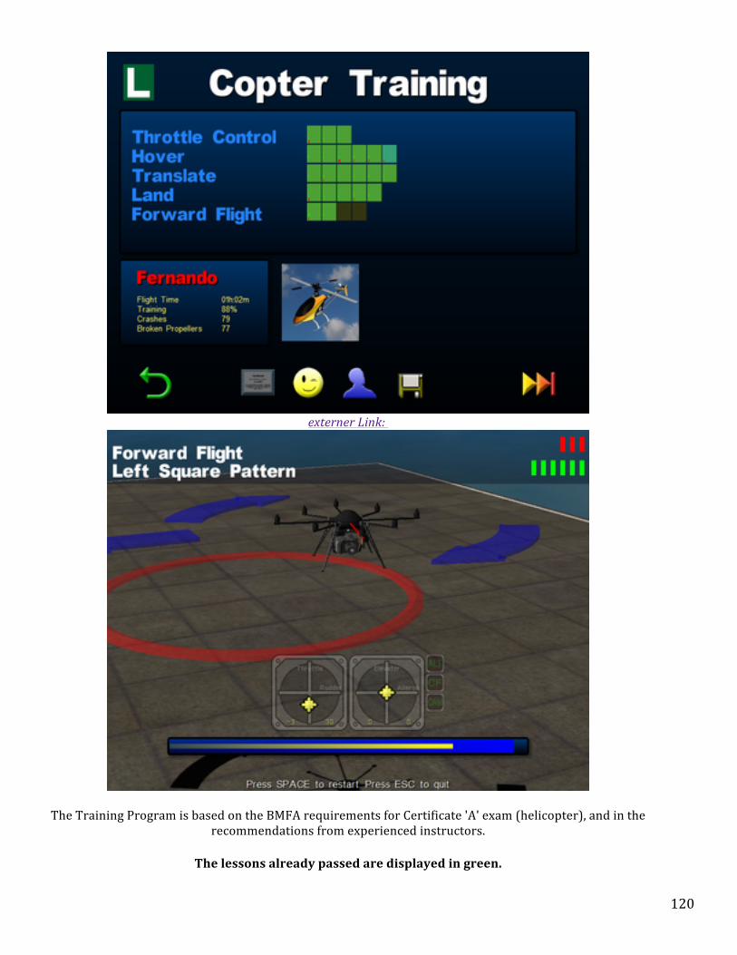
120
externer Link:
The Training Program is based on the BMFA requirements for Certificate 'A' exam (helicopter), and in the recommendations from experienced instructors.
The lessons already passed are displayed in green.

121
The lessons attempted but failed are shown in red. The lesson in blue is the next recommended one.
There is a red dot for each time the lesson was failed. There is a green dot for each time the lesson was passed.
Link for the Software update
http://www.aerosimrc.com/j/index.php/en/downloads
This is the perfect training for long winter evenings and while your waiting for parts.
Basic Flight Maneuvers
Basic Flight Training Maneuvers This section describes a series of basic flight maneuvers that should be mastered before preceding further. While the addition of the flight navigation systems adds a great measure of ease and confidence to flying the MK, the following procedures are critical to basic skills and should be practiced in on ongoing basis. Take your time and practice these maneuvers until you can do them without hesitation. If you practice the same maneuver on a flight simulator and than proceed to practice with the MK, your training will be much accelerated. Exercise 1 -‐ Takeoff and Landing Double check that the conditions for flying are still safe (no people entered the flying area without you noticing as you were focused on the model, nose of model is pointing away from you and into the wind, nothing hanging loose from the model) If the flying conditions are still OK, switch the motor on (throttle stick in lower right corner until the motors start up to idle). Increase the throttle stick until the model gets light on its feet. Time for lift-‐off! Increase the throttle stick a little bit faster so that the MK quickly lifts off. You want it to go to an altitude of 3 feet or more to get out of ground turbulence caused by the downward airflow from the propellers. Once you are at 30-‐50cm, gradually reduce the throttle to slow down the ascent, and gradually decrease it further to descend slowly land again. Do NOT suddenly decrease the throttle or you will crash. If you start descending too quickly, increase the throttle a little bit to slow down the descent. Unfortunately the very sensors that the MK uses to keep it level etc will cause it to 'bunny hop' if you are not careful. Basically the MK behaves differently as it gets closer to the ground due ground effect. That is the downwash of the props against the ground affecting the lift and stability. What you need to do is to bring the MK down to about 3 feet then slowly descend keeping the MK level, once you are just about to touch the ground reduce the throttle completely. If you reduce it slightly it will bounce, the sensor will increase the gas and it will rise, you will then reduce the gas, the sensor will also reduce the gas and it will bounce again and so on. Reducing the gas completely means the sensor's input is not enough to give it enough lift to keep it in the air. If the MK drifts a bit during this phase, just reposition it on the ground between take-‐offs. We're not yet going to try flying it back to its position. Practice lift-‐off and landing repeatedly until you can fully control it and landings are soft and smooth. Reduce the throttle to idle between landings and recheck the environment! If for some reason something goes wrong and the MK lands on its side or upside down, IMMEDIATELY turn

122
off the motors (throttle stick in bottom left corner until the motors stop) to avoid unnecessary damage to ESCs, propellers or motors). Reposition it, and check for damage. Reposition yourself and recheck the environment. Restart the motors (throttle stick in bottom right corner until motors start) and restart lift-‐off and landing practice.
Remember: Small stick movements! If you can't get the MK back to its starting position, it is safer for both the MK and yourself to land, manually reposition it and restart, rather than to continue to try and correct drift which could lead to disorientation followed by crashing the model into the ground or yourself. Exercise-‐2 -‐ Hovering Once you are comfortable with takeoff and landing, it’s time to practice one of the important maneuvers, hovering. With the MK pointed away from you and at chest height to avoid ground effect, hold the aircraft in a hover. With the nose continuing to point away from you, lightly maneuver roll left and right, and pitch fore and aft. Practice this for 10 minutes or until your battery gets low. This is called nose-‐out flying and is he easiest way for new pilots to get a good feel for the MK. Moving left or right, or forward or aft is of course great. But the big advantage of a MK is that it can hover. It can hang still above a given point. Hovering an MK means that in addition to the self-‐stabilization by the flight controller you provide some additional control inputs to keep the MK over the same spot on the ground at the same altitude. Carefully combing the roll, nick, yaw and throttle inputs to correct drift in any of these four axis, trying to keep the model in a stable hover at between 1 and 2 meters above its take-‐off position. If the craft moves too far out of the hover area, just land and reposition it. Hovering is a very critical flying skill so practice it extensively. It may require several hours of practice under different conditions to master it to such a degree that even in some wind you can keep the model within 20cm of its intended hovering position. If you can do this well, you will most likely be able to get out of trouble during other maneuvers by going into a hover quickly, reassessing the situation, and flying to a safer position or landing spot. At first, just practice over the general area of your starting point. Later consider marking a point on the ground (e.g. a helipad made from plywood or canvas, or a pylon or plastic bottle) and hover exactly above that point. You may be surprised how difficult it can be to stay correctly above a clearly marked spot for several minutes. Once you can control the MK left/right and forward/backward, do some practice on rudder / yaw. From a hover position, carefully move the rudder stick to turn the nose of the MK approx 45 degrees to the left or right, and then yaw back. You do not yet want to go further than 60-‐70 degrees because you will quickly run into control reversal and get disoriented.
Exercise -‐3 House pattern A typical flying maneuver is the "house". Lift-‐off, at about breast height hover for about 5 seconds, then fly 3-‐4 meters sideways, again hover for about 5 seconds and land. Then do the same in opposite direction. Keep the nose pointing away from you (tail-‐in).
Exercise-‐4 -‐ Square-‐Flying Fly along the borders of a square and break at the edges for about 5 seconds. Chose a height about 6 feet and a side-‐about 6 feet in length. The nose always points away from the pilot's position. Repeat this exercise for 15-‐20 minutes.
Exercise-‐5 Hover Sideways Its very important to break the habit of the fixed view to your copter. Think like you were hovering in the model and from the left to the right side. Turn the nose in flight-‐direction and than gradually

123
bring it to 90 degrees from there. If you loose orientations, bring the nose back to the starting position and try again.
Exercise-‐6 Square pattern Mark four corners of a 3 to 5 meter square around your lift-‐off position. Lift-‐off, hover for 5 seconds, and then fly the shortest line to the first corner. Hover above this corner for 5 seconds and then fly to the next corner in a direct line, hover for 5 seconds, etc. Do this in both directions (clockwise and counter-‐clockwise). You may have a clear preference but should be able to do this in both directions. Also occasionally fly across diagonally from one corner to the opposite. Make sure you do this purposefully: have a flight plan and don't adapt going from one corner to the diagonal corner instead of the next because you drifted off a bit and it looks so sloppy if you have to fly a curve instead of a straight line. During movement from one corner to another keep the nose directed away from you. Fly at a constant altitude (about chest height). Try flying at a constant speed. Keep the speed low to allow easy transition to hover without overshooting the mark.
Exercise-‐7 Circles Plot out or envision a 50 ft circle on the ground, Take off and fly the circle alternating clockwise and counter clockwise. Practice with the nose pointing away from you(Nose-‐out). Exercise-‐8 Nose Flying Sideways Once you have mastered flying house and square patterns "tail in", it is time to start gradually getting used to flying the MK more from the models' perspective. So repeat the above house pattern, but now when preparing to move sideways, in the hover yaw (turn) the nose a bit (30-‐60 degrees) in the direction you will be flying in, and then try flying the same straight line that you could fly so nicely "tail in". Repeat this until you can comfortable turn the nose the full 90 degrees in the direction you want to fly in and not confuse the roll and nick directions. Once you can fly the house pattern nose sideways, you can also practice the square. However when moving back towards you, either yaw the model so that it is again nose-‐out, or fly it sideways (alternate this according to your "flight plan"). Tip: Flying nose sideways can be easier if you also turn your body sideways a bit. In fact you will then be flying tail-‐in again but with the model to your left or right. This trick does not help much in the transition to nose-‐in flying. But keep in mind if you get into trouble during flights later on due to some disorientation. It may help you recover.
Exercise -‐9 The walk-‐along For the walk-‐along you walk along a path with the MK tagging along at a fixed position in front, or next to you. If you reach a corner, of course you must yaw the MK to be tail-‐in or nose-‐in or sideways again, whichever mode of flying you want to practice. Of course you do have to make sure there are no other people walking the path. Practical use of this exercise is mainly in the RCAP arena where you often do walk around a bit to change your position and that of the model to take pictures from a different angle. Also the change in relative positions between you and the model forces you to focus on the model and not orientate your control movements to the position of the model relative to its surroundings.
Exercise 10 -‐ The circle me For the circle me, the intent is to fly a full circle around yourself, or another given target, at a fixed distance and yawing at a same angular rate as the craft is moving through the circle. So if you fly it tail-‐in, the craft should be looking straight out from the circle (and if shooting video this would

124
result in a wide panorama). If flying nose-‐in it should be looking you in the eye at all times. Try to also maintain a constant altitude during this exercise. And make sure that there are no people standing anywhere near you if you do this at practice hover altitudes (1-‐2 meters). This is again an exercise which is useful later on for RCAP flying. However it also helps improve control of left and right sticks.
Exercise 11 -‐ Flying nose-‐in The most difficult way of flying is with the models nose pointed at you. Once you have mastered flying nose sideways, you're almost there. There are now two ways to progress. 1.You can restart hovering practice but now lifting off with the models' nose pointed at you. The advantage of this approach is that you learn to transition well from nose in to hover to flight and vice versa, a critical ability to get out of trouble. If you start with hovering nose-‐in just repeat the house and square patterns after that. 2. Alternatively you can gradually progress from nose-‐sideways flying the house and square figures to flying them with nose in the direction of flight at all times, and eventually to fully nose in (i.e. flying away from you with the noise pointing at you, and flying from left to right or right to left with the nose pointing at you). Before you do this, practice 360 degree yaw in both directions from normal tail-‐in hover. In all cases make sure you practice flying the square nose-‐in in both directions (clockwise and counter-‐clockwise). Practice nose in flying very, very extensively. You must eventually be able to transition from tail-‐in to nose-‐sideways to nose-‐in flying without any hesitations or mistakes with respect to control inputs for flying your intended pattern / direction, and transition at a moment’s notice to a hover. If you have trouble controlling the aircraft nose-‐in at some point, just yaw it back tail-‐in and regain hover position. Never panic and pull the throttle down !!! If necessary, slightly increase the throttle to remain between 1 and 2 meters above the ground until you have been able to regain hover. If all else fails, very carefully decrease the throttle and land. Tip: Until you have mastered nose-‐in flying, do NOT attempt either aerial photography or aerobatic flying. Not having mastered this skill properly will eventually cost you your camera or model.

125
Section 11 -‐ Normal Operations Maiden Flight of Okto2
Now that you have a large investment of money and time into your MK, do not be in a rush to perform maneuvers beyond your capability. You must spend time on a simulator, and follow the flight training suggestions in a planned and purposeful manner. With less than 15 minutes flying time per battery, it will take some time before you are proficient enough to carry an expensive camera. Now you are at a point of enjoying the fruit of your labor, be careful and have fun!
First Flight Checklist
Please, please put in six hours of flying on a good simulator before any flying. I recommend the AeroSIM RC flight simulator, but, any sim with a quad model will do. The following steps cover pre-‐flight of the Kopter using the basic Flt-‐Ctrl w/barometric sensor (height) only it does not take into consideration adjustment of the Navi, Mag or GPS.
• Remove the props • Check all fasteners screws and velcro for tightness and security. • Make sure your transmitter/receiver has been bound. • Check MKTools for proper, mixer, k-‐value, switch, and poti settings. • Set emergency time setting in MKTool to maximum 247 which equals about 24 seconds. In case you lose
radio signal it will give you a short time to react. • Set emergency gas setting to 45. • Connect your now charged battery and let the electronics initialize. You will hear a chirp from each motor
and each will make a short revolution. • Confirm that initial gyro and acc leveling calibration has been accomplished. • Generally, get the copter into a level position, If proper calibration was accomplished in the initial setup,
than, you only need to get the copter close to level. • Switch flight mode to beginner (mode 3) by holding left stick upper left while holding right stick upper
center. Hold until you hear 3 beeps. You only need do this once to set Kopter to mode 3 unless of course you

126
update the firmware at a later time. If you don’t hear 3 beeps you are in the wrong flight parameter, repeat above process.
• Start motors by holding left stick lower right. Do a test run up of the motors using the transmitter before installing the props and double check to be sure the rotation on each motor is correct. This run up will also tell you that your throttle is set up correctly and not reversed. At idle the left stick should be closest to you.
• Stop motors by holding the left stick in the lower left position, disconnect the battery, and install the props making sure they are on the correct motor and that the hex screws are tight. I put a small stainless steel washer under the head of each hex screw so the screw heads wouldn’t dig into the plastic prop when tightened.. Remember that you have props that rotate clockwise and some that rotate counterclockwise. The props are not the same, get them in the right order or the Kopter can’t fly.
• Take the bird outside turn on the transmitter, and then connect the battery to the bird. Once the electronics have initialized (each motor will make short rotation and beep, green light only on flight control board. Set the Kopter on the ground so it is stationary and hold left stick upper left position until you hear 3 beeps. This calibrates gyros (the bird must be stationary but not necessarily level here) This particular calibration needs to be done each and every time before you fly.
• Hold left stick lower right which starts all motors at idle. • It is recommended that before you attempt your first flight slowly run up the motors until the Kopter starts
to get light on the landing gear. At this point check your controls nick, roll, and yaw to be sure movement on the Kopter is correct and in sync with stick movements. If you need to slightly trim out the controls do so now. Take it easy here as you don’t want to make the bird so light and over control testing to the point that you roll the Kopter over. If you need to make switch reversals on your transmitter power down the Kopter and make them now, before lifting off.
Preflight Checklist
• Check the reliability of the MikroKopter. • The flight battery and transmitter battery must be fully charged • Watch for visible damage such as for loose screws, broken, unbalanced or damaged propellers, faulty
connectors or solder joints, etc. • The propeller must be in a good condition and securely mounted. The rotors must spin smoothly and there
shall be no objects are in the rotational plane of the propellers and can get into it. Rotating propeller ends
127
are dangerous to touch -‐ never touch with fingers and other body parts a rotating propeller. • Ensure the appropriate to the audible beeps when auto lipo-‐detection is enabled. 4 * beep means 4s Lipo • Ensure that the channel of the remote control is free and you're within range of the transmitter • The sensors must be calibrated (When the motors are off: move yaw-‐ and gas stick into upper left corner
until it beeps) • Different settings can result in fundamentally different flight characteristics and occupation of the Channel
functions. Make sure that you are familiar with the setting and its features • After starting the motors, all motors must run and rotate evenly. Please fly carefully in small altitude until
you know that everything is working fine. • Perform a pre-‐flight check by (off checklist, see below) • Start manually -‐ switch off altitude control and GPS
Note: Get a good GPS lock if you are going the use the navigation functions. As soon as the green light on top of the GPS is blinking you have sufficient satellites to get GPS hold. The MK will automatically remember this as home when you calibrate the gyros, just be sure that the home position has some room around it because the MK might over run the home position a bit. Warning: Come Home (CH) only works if you have GPS fix BEFORE the motor starts. You should make sure you have GPS fix when your motor start otherwise it will return to the last 'home location' that it knows.
Inflight Standards
• Do not take risks! Your own safety and that of your environment depend on the good behavior of the pilot. • Always keep a distance from people, animals and objects. Improper operation can cause serious injury and
property damage! • Never fly towards viewers and avoid overflights of spectator • Keep in mind that viewers could get close to the MikroKopter, without being aware of potential dangers • Always turn off the MikroKopter first and disconnect the flight battery before turning off the transmitter • Only fly in sight. In the case of a manual control, you must be able to see the position and attitude • Never rely 100% on functions such as GPS, compass, or altitude control. You must always be able to take
manual control of the MikroKopter • Reduce the gas or switch off the motors in case of a crash or failure • Do not fly in blocked air space, such as in the vicinity of airports, etc. • Pay attention to undervoltage warning -‐ a flight to empty battery can cause damage to the Lipos and crash • If a defect or malfunction has occurred, it must be corrected before the next start • In case of use of GPS, the position of the MikroKopter can change suddenly some meters.
Post Flight Checklist
• Disconnect the battery • Check for damage • Make sure that the propellers are not damaged • See the Handling and safety precautions of Lipos • After a crash the sensors and electronics might be damaged. Before the next start everything must be
checked
Cold Weather Flying
Batteries Batteries used in MK and Transmitter are very susceptible to cold weather flying (below freezing). Expect half capacity if battery cools to 10F. Batteries should be kept warm in an insulated box if possible. Electronics The electronics do not care about cold, however, once the MK and transmitter have become frozen, condensation may form on the electronics when brought into a warm room. In this case, do not apply
128
power until condensation has evaporated. Propellers The EPP props that come standard on the MK become very brittle in cold weather and may snap off even with light contact with the ground. Fingers Fingers quickly become numb in cold weather and control sensitivity fads with numbness.
Flight Log
Keeping track of your flight time and experiences during flight is a valuable learning tool. Not only will you keep track of operating time on the MK, but, you will keep track of your learning progress. Every flight should be an opportunity to learn something, whether it's a bit of "Nose IN" flying or hovering around a light pole. Before you go out to fly, make a plan for what you are going to do and visualize it in your mind. After the flight, review to data card, videos, and any lessons learned during the flight. Write them down, it will accelerate your learning and in a way, extend the "Joy of Flight". Most pilots are required to keep a Flight Log, there is a reason for it -‐-‐ documenting experience and tracking aircraft use. A simple $5 notebook that you can buy at your local discount store would be sufficient and prove to be a fun and valuable tool. You can also keep your preflight checklist and other things to remember inside the cover. Some day, in the not to distant future, this may become a requirement for anyone operating these sophisticated flying machines.

129
Section 12 -‐ Emergencies In-‐Flight emergencies, as with any emergency is the least practiced ans least experiences situation that you will encounter when flying. While many emergencies are not planned, proper mainenance and calibration will greatly reduce the chances of an emergency situation occurring. Also, knowing the aircraft limits and your own can help you avoid situations that may lead to an emergency situation. Routine habits formed by following "Best Practices" for flying operations will create a mindset that the worst case scenario could happen on any flight and lead to a thought process of emergency "what if's". Thorough checklists help preparedness Simulator practice Since it would be a very expensive and risly operation to practice "real" emergencies, simulators fill the gap. All major airlines and the military use simulators extensively to prepare pilits for emergency situations. Get a good simulator and practice. Loss of Communication
• Emergency Gas Time • Emergency gas Setting • Coming Home Failsafe
Rescue maneuvers! A important rescue maneuver is to practice fast yaw into the nose out position where situational awareness is easiest to acquire. Note: Make a relatively slow descents if coming straight down, the prop wash disturbs the gyros and altimeter.
• Consider a locator beacon installation • Consider a diversity board • Consider installation of isolation board

130
Section 13 -‐ Photography
Aerial Photography Flying for aerial photography poses several unusual challenges. Compared to normal or aerobatic RC flying you are usually much more restricted in the space you have to take off and land from, you fly closer to people, property, and all sorts of obstacles, and you fly (much) higher than you do for normal or aerobatic RC flying. In addition you if you fly alone you will also have to control the camera. And for video flying you want your flight to be fluent so that the resultant movie requires limited editing. DO NOT do any aerial photography or aerial video flying until you are confident that you can properly control the MK under the conditions you will need to fly in. Camera mounts As with any muti-‐rotor aircraft, there are inherent vibrations due to structural design, motor imperfections, and unbalanced propellers. With proper attention much of the vibration can be greatly reduces, but it impossible to eliminate all vibration. This is were a quality camera mount that has good vibration damping design comes in. Photoship One, MK HiSite, Sky Rover, and MD2 are all excellent mounts. In addition to these, simple solutions such as foam pads and rubber grommets can be very effective at reducing vibration. Experiment with the simple solutions first and than move up until you find one that meets your needs. Cameras Aerial photography has always demanded very high resolution cameras because of the altitude required for safe flight and FAA regulations. One of the great advantages of the MK is that is can fly at a much lower altitude and obtain the same, quality images and often times even better. While the larger MK’s are capable of carrying heavy DSLR’s, in many cases, with the advancement in camera technology, quality aerial photography is possible even with the lighter MK’s. Military drone operations use microcameras with outstanding success. Select a camera to meets your budget and you will be amazed at the results of even the consumer grade cameras. While success in still imagery from the MK can be quit easily achieved, video is another ball game and will take a lot more practice and experimentation. Extend the basic flying practice with the following maneuvers in an open field:
Exercise AP1. Practice flying up to 5-‐10 meters, and then hover. Practice yawing 360 degrees in steps of about 15 degrees. Press the shutter control between each step of the yaw. After doing a full turn practice tilting the camera mount down about 15 degrees and doing another stepwise 360-‐degree yaw. Do this in both directions while maintaining a stable hover. Exercise AP2. Once you are confident that you can control the MK at this altitude, go up to about 20 meters and repeat the exercise. Note that from about 20 meters and up the altitude hold function can be used quite well to help stabilize the altitude. However you will still have to control nick, roll and yaw. Do not fly any significant distances horizontally until your are confident in hovering at larger altitudes. Only increase your altitude in a stepwise fashion after you are confident at a current altitude. Exercise AP3. The maximum altitude you can fly under visual control is the altitude at which you can still sufficiently see the position of the MK to allow you to properly control the hover. This will vary based on size of the MK, eyesight of the pilot, and experience. For most people it will probably be between 50 and 75 meters. That may not seem like much, but remember that a 20-‐storey building is usually about 60 meters so you can still take good AP pictures of even such a high building from an MK. You can carefully test this envelope in an open field away from people and houses. Never try to extend this envelope beyond your

131
known capabilities while doing an actual RC AP flight. Exercise AP4. Once you can confidently hover at altitude, practice flying a virtual square of about 50 meters in each direction at the same altitudes, starting at about 10 meters and then working your way up. This is an important maneuver to master as you usually want to take your pictures from different angles. Exercise AP5. For aerial video flying after having mastered the above exercises draw up a clear flight plan in which you determine a flight path and direction of view of the MK at each point in its path. Start easy with a square or circle at about 10 meters with a gradual ascent (either vertical or along a slope) yawing the MK if needed to keep the nose (camera) pointed at the intended target(s). Gradually increase the complexity (e.g. with hover points where you do a particular yaw, tilting of the camera mount, increasing the altitude, etc). Also practice lower altitude flights along curving paths as for AV you may also be following e.g. speedboats or go-‐carts from altitudes of just 1-‐3 meters. Exercise AP6. Gradually allow yourself to fly in increasing wind conditions. Although you preferably want only light winds, a reasonably powerful MK for aerial photography, and its pilot, should be capable of handling wind speeds up to 45 km/h. Once you have mastered the above, find a quiet park or field with some obstacles of different height (e.g. some spread out trees) to add complexity. Try to stay well clear of the trees. Remember that they are alive and always trying to grab your MK out of the sky. But think of the trees as houses, obstacles, and targets, and use them to gradually increase the complexity of you flying conditions. Note down an outline of your flight plan before every flight, or describe it after a flight. It may well be that you want to make a very similar flight at another time at the same site to show changes over time. The closer you can copy your previous flight the better the results will be. Over time it is very likely that you will progress to flying in more densely populated areas. As indicated above, be obsessively compulsive about the quality and condition of your aircraft and RC system. Do not compromise on safety.
Camera Mounts
Photoshipone MKTR The is much debate on what is the best camera mount to buy, and, in actuality, nothing is perfect -‐-‐yet. That said, the MKTr is what I bought, so, I will try to do the best I can with this mount and tweak it until it works the best that it can. Note: If you intention is mostly photography and not video, you will have much less difficulty with the calibration and setup. The MKTr platform is relatively easy to assemble, although the takes a few hours. The attached manual is quit thorough. There are other quality mounts, but, I bought this one primarily for it's light weight.

132
Don't be in a hurry to mount it, get some flying time first. I tried tried it too soon and broke a strut on a hard landing. So, I'm on hold with this for now. Here is the Photshipone Website
Cameras -‐ decisions-‐decisions??????
10/26/2011 The Sony NEX 7 is the advance in the new small cameras. coming out in November 2011, with it's 24MP sensor and light weight, it will be a great camera for the MK even without an AV output for FPV.

133
11/20/2010 -‐ I have been debating which camera to buy for the Okto2. I am hesitant to go with the Canon2T1 as it will make the Okto operate continuously above 80% power. The 2Ti is a great camera, but, I am waiting until January 2011 for to Panasonic GF-‐2 to be released. The GF-‐2 looks very promising and worth the wait for now.
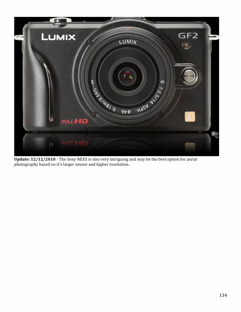
134
Update: 12/12/2010 -‐ The Sony NEX5 is also very intriguing and may be the best option for aerial photography based on it's larger sensor and higher resolution.

135
For now,I am practicing with my GoPro and will decide on a better camera when I get more comfortable with the flying.

136
Section 14 -‐ Performance Data Flight Times
MK-‐GPX
Contents
1. 1 Instructions for MK_GPX software 1.1 Introduction 1.1.1 Purpose 1.1.2 Download 1.1.3 Beta version 0.86 1.2 Operation of the software 1.2.1 The MK-‐GPX program interface 1.2.2 The MK-‐GPX menu 1.3 The program interface 1.3.1 The GPX data 1.3.2 Selected data to evaluate 1.3.3 All data analyzed 1.4 Analysis of the data 1.4.1 The graph selection 1.4.2 The data control 1.4.3 The meaning of the flags in the MK Evaluation Software 1.4.4 The graphical display 1.4.5 Compass/Course 1.4.6 Instruments to indicate the attitude 1.5 The log page 1.5.1 Flight Stats 1.6 The settings 1.6.1 Axes 1.6.2 Graphics 1.6.3 Selectable Graphics 1.6.4 Limits 1.6.5 Other
Resource Information The following contents is derived form the primary MK website at: http://www.mikrokopter.de/ucwiki/wemau/#awsoft Please check this link for additional updated and information.
Instructions for MK_GPX software
Introduction
As with any sophisticated aircraft, a flight recorder is often used to analyses aircraft performance both during routine flights and especially when something is not working right and particularly if component or pilot error has lead to a crash. Having this flight data available can help not only the MK operator learn valuable insight into what happened, but, it may also provide important information to other MK owners about potential problem areas of operation that can
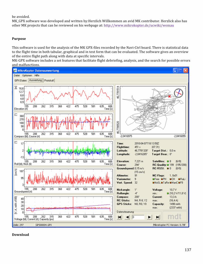
137
be avoided. MK_GPX software was developed and written by:Herzlich Willkommen an avid MK contributor. Herzlick also has other MK projects that can be reviewed on his webpage at: http://www.mikrokopter.de/ucwiki/wemau
Purpose
This software is used for the analysis of the MK GPX-‐files recorded by the Navi-‐Ctrl board. There is statistical data to the flight time in both tabular, graphical and in text form that can be evaluated. The software gives an overview of the entire flight path along with data at specific intervals. MK-‐GPX software includes a set features that facilitate flight debriefing, analysis, and the search for possible errors and malfunctions.
Download

138
MK-‐GPX software can be downloaded at this link: [ http://www.mdtweb.de/images/stories/downloads/MK_GPX_0016.zip ]
Beta version 0.86
http://www.mdtweb.de/images/stories/betatest/MK_GPX_0019_beta.zip
Operation of the software
While the program interface is fairly self-‐explanatory, below is an explanation of its major functions.
Note: Active Logging Note: Logging will only occur when the motors are on AND there's a gps fix
The MK-‐GPX program interface
The display consists of three areas. The menu, the desktop, which is the GPX data as a tree structure, tables and graphics as well as a single data set and shows a statistical processing of data. In the third area, the status bar, the currently displayed record and the filename and the assisted MikroKopter version be looked up.
•
The MK-‐GPX menu

139
The menu includes three groups, "File", "Options" and "Help". On it, the following will be discussed in more detail. File
• Under this menu there are three menu items: Open Opens a selected GPX file. Print Print the log page (s). End Exits the program.
• Options
• Here you will find several items: Horizon The artificial horizon is switched on or off. Compass The compass is turned on or off. Altitude The altimeter is switched on or off. Airspeed The airspeed is displayed or hidden. Various The variometer is switched on or off. AutoShow By clicking on this option can be turned on or off. It serves in the active state, after the
selection of any or all records to jump directly to the evaluation. 1024 x 600
By activating this option, the user interface for smaller screens with a resolution of 1024 x 600 pixels can be adjusted.
Settings Here, the appearance and settings of the graphics, the limits of the received signals and the LiPocell voltage, and the choice of language are made.
• Help
• The Help menu contains three menu items: MK-‐GPX Help The Help file. MK-‐GPX Homepage
A link leading to the site of the developer program.
Info Here is the current version number, supported MikroKopter version and the copyright reference.
The program interface
The GPX data
Two areas show the contents of the loaded GPX file. On the left side of the structure of the file is displayed as a tree, which with the help of the "+" or -‐ to be opened or closed symbols "." On the right side of the file appears in tabular form. Here, a single data set can be selected, which is then displayed in the analysis.
Selected data to evaluate
Selects several or even all of the records can be made via the context menu (right mouse button), a range selection, which then is also in the evaluation.
All data analyzed
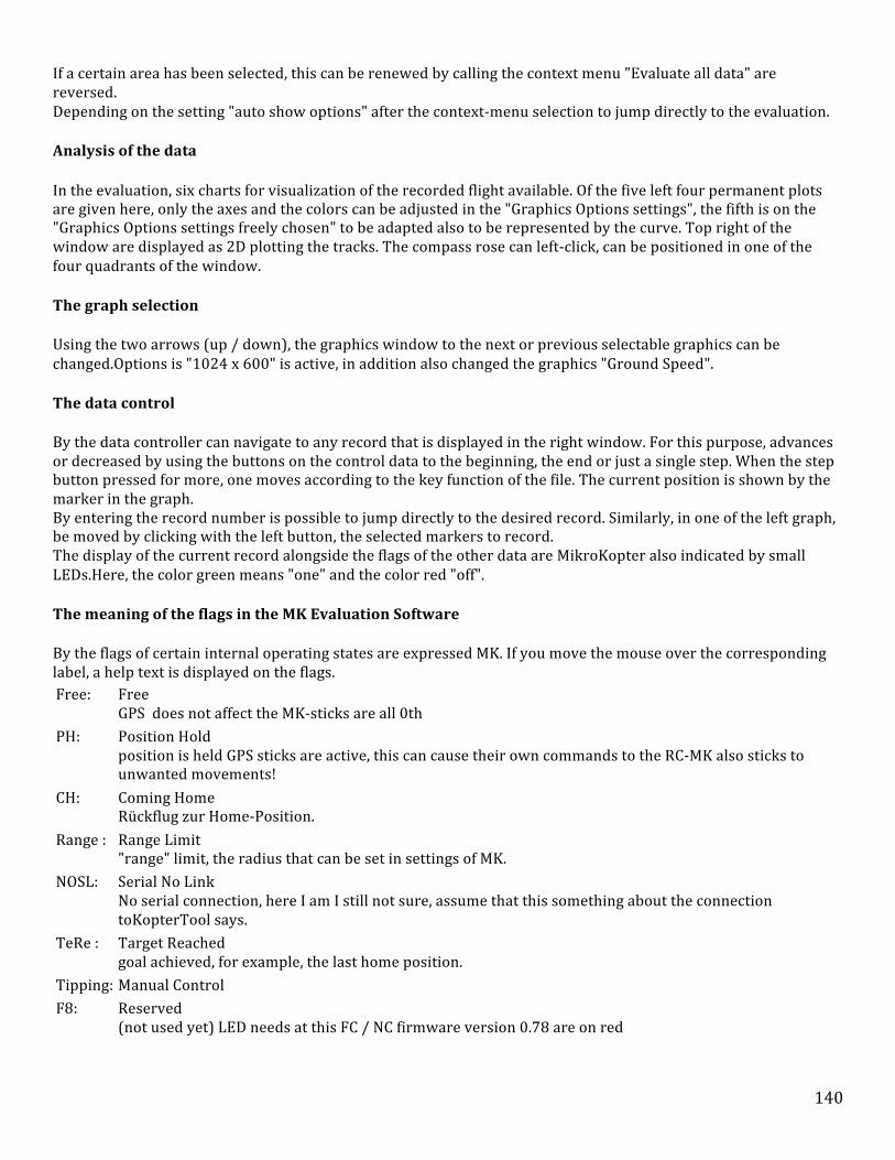
140
If a certain area has been selected, this can be renewed by calling the context menu "Evaluate all data" are reversed. Depending on the setting "auto show options" after the context-‐menu selection to jump directly to the evaluation.
Analysis of the data
In the evaluation, six charts for visualization of the recorded flight available. Of the five left four permanent plots are given here, only the axes and the colors can be adjusted in the "Graphics Options settings", the fifth is on the "Graphics Options settings freely chosen" to be adapted also to be represented by the curve. Top right of the window are displayed as 2D plotting the tracks. The compass rose can left-‐click, can be positioned in one of the four quadrants of the window.
The graph selection
Using the two arrows (up / down), the graphics window to the next or previous selectable graphics can be changed.Options is "1024 x 600" is active, in addition also changed the graphics "Ground Speed".
The data control
By the data controller can navigate to any record that is displayed in the right window. For this purpose, advances or decreased by using the buttons on the control data to the beginning, the end or just a single step. When the step button pressed for more, one moves according to the key function of the file. The current position is shown by the marker in the graph. By entering the record number is possible to jump directly to the desired record. Similarly, in one of the left graph, be moved by clicking with the left button, the selected markers to record. The display of the current record alongside the flags of the other data are MikroKopter also indicated by small LEDs.Here, the color green means "one" and the color red "off".
The meaning of the flags in the MK Evaluation Software
By the flags of certain internal operating states are expressed MK. If you move the mouse over the corresponding label, a help text is displayed on the flags. Free: Free
GPS does not affect the MK-‐sticks are all 0th PH: Position Hold
position is held GPS sticks are active, this can cause their own commands to the RC-‐MK also sticks to unwanted movements!
CH: Coming Home Rückflug zur Home-‐Position.
Range : Range Limit "range" limit, the radius that can be set in settings of MK.
NOSL: Serial No Link No serial connection, here I am I still not sure, assume that this something about the connection toKopterTool says.
TeRe : Target Reached goal achieved, for example, the last home position.
Tipping: Manual Control F8: Reserved
(not used yet) LED needs at this FC / NC firmware version 0.78 are on red

141
The graphical display
The displays of flight parameters are on the left side of the window below one another in order to get a good chronological overview of the individual curves. Graphics that contain multiple curves lead in naming the color associated with in brackets, for example, blue (bl). Here, mainly the usual technical abbreviations are used for the color (usually the first two letters).
Compass/Course
The Compass (blue) shows the orientation of the MK-‐nose. The course, however, shows the movement direction (forward, backward or side) of the Mikrokopter on.
•
Instruments to indicate the attitude
The five instruments are on the menu options on or off. They show the most important information to visually, can be freely arranged and scaled.
•

142
The log page
The log (almost) all the major events, beginning with the date of loading a new file to display notes. This is in addition to the maximum of the fully supported firmware MikroKopter also logs the current program version with links to the developer side, and the analysis time and the file name with path. In another line, the approximate setting of "GPX Logging" in the ini file that refers to the GPX-‐lap recording is displayed. The accuracy of the value increases with the file size under investigation. When evaluating any faults and fault location are noted. Also supported variables and "extensions" of the GPX file are marked for inspection.
Flight Stats
The most important data of the recording with Min is -‐ and maximum values and may be registered with references to specific abnormalities.
The settings
The surface of this window is divided into four different areas, the axes of the graph, the selectable graphics and other settings. The window can be parallel to the main window open, so that the changes made will be evaluated immediately.
Axes
Here you can set the five graphs. This requires the appropriate checkbox is disabled. The X-‐axis can be changed only in common for all graphs. By dividing the input field, the subdivision of the axis to be adjusted as needed. The change places the decimal part of the displayed number in the Y-‐axis is "min." Through the fields and "max." The appropriate limit to be set. Press the "Apply" performs the changes.
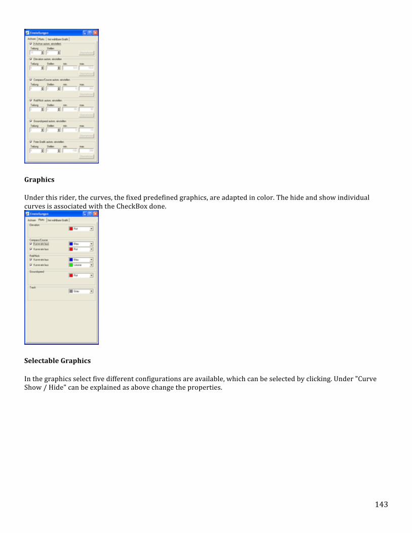
143
•
Graphics
Under this rider, the curves, the fixed predefined graphics, are adapted in color. The hide and show individual curves is associated with the CheckBox done.
•
Selectable Graphics
In the graphics select five different configurations are available, which can be selected by clicking. Under "Curve Show / Hide" can be explained as above change the properties.

144
•
Limits
The setting of the thresholds used for the rapid detection of possible error sources, which are displayed in the statistics in the report and in the evaluation of small LEDs in the colors "green" (ok), "yellow" (borderline), "red" (critical ) and are "blinking red" (see very critical). The limits can be adjusted using the input boxes to the desired values.
• In the box "Receive / alert levels" are the settings for the limits of the satellite, made for RC and RC-‐Quality RSSI (Received Signal Strength Indicator). In the box "LiPo / warning levels" is the voltage of the LiPo cell, shown in 10-‐volt tel [dV] (deciVolt), is set.
Other
Here you can adjust the desired language. The selected language will be immediately effective for most areas. An exception is the record, here is the change take effect until after the (re) loading a file.

145
146
Section 15 -‐ Troubleshooting Contents
1 Help -‐ My MK does not fly? 1.1 Introduction 1.2 Assumptions 1.3 When NOT to fly if trying to solve any problems 2 Taking Off 2.1 Props do not rotate 2.2 Props rotate but MK will not lift off the ground 2.3 MK lifts but immediately flips over 3 Hovering 3.1 MK lifts and rotates slowly 3.2 MK will not stay still 4 Controlling Height 4.1 MK continues to ascend 4.2 MK falls slowly 5 Moving the MK 5.1 MK does not move in correct direction 5.2 MK oscillates to a fro about central axis 5.3 MK diffficult to control 6 Landing the MK 6.1 MK bounces on the ground 6.2 MK drops from height and cannot recover 6.3 MK behaves strangely when trying to land
Help -‐ My MK does not fly?
Introduction
The purpose of this page is to try and solve some of the more common problems some people have with flying their MK's. Unfortunately most problems can be put down to pilot error as the MK system is basically very stable. However notwithstanding pilot error it is sometimes very difficult to see a fault before the MK has crashed. In order to try and establish what the problem may cause we will use a series of pre-‐crash symptoms to root out the potential cause. It is fair to say that most problems are quite simple and usually easily solved.
Assumptions
Before we delve into establishing what the problem may be we will assume the following: • -‐ The MK is a MikroKopter, has the Standard Software loaded and is using the Standard Hardware
-‐ The frame is configured to a standard frame configuration and has 4 props and motors -‐ The batteries are fully charged on the Transmitter (TX) and MK -‐ The MK is being operated within the range of the TX -‐ Any alterations and testing is carried out at your own risk and you do not put yourself or anyone else at risk -‐ The MK is in sound condition and capable of flight -‐ The props are all the same size type and the motors are all the same size and type -‐ You are flying within the rules and regulations of the CAA and any local bylaws

147
When NOT to fly if trying to solve any problems
• -‐ In the rain, heavy fog or at the risk of heavy rain or freezing conditions -‐ In winds above Force 4 -‐ 25.6kmh (16mph). Ideally only up to a Force 3 -‐ Over people or built up areas -‐ In poor visibility -‐ Out of range of the MK and TX -‐ Close to or over water This list is by no means complete and extensive. It assumes that you will use common sense and know that the MK can be very dangerous when it is out of control. Not only can it cause serious injury or damage to property it can also prove to be very costly.
Taking Off
Props do not rotate
Problem may be caused by one or some of the following: • -‐ GAS not set to the correct channel o -‐ Assign GAS stick to the correct channel in the MK tool
-‐ TX not transmitting on correct TX channel o -‐Rescan the TX to find the correct RX channel or change the crystal
-‐ RX not plugged in or connector reversed o -‐ Plug the Flight controller board into RX, or reverse the RX plug
-‐ MK not switched on or battery not connected o -‐ Check switch and battery connections
-‐ Motors not free to rotate o -‐ Motors should offer little resistance and spin freely. The rotation will appear to be a 'lumpy' but this is
normal -‐ Motors not connected
o -‐ Connect the motors
Props rotate but MK will not lift off the ground
Problem may be caused by one or some of the following: • -‐ Motors not rotating the right way o -‐ Swap any 2 connections to the motor to change their direction
-‐ Correct props on the correct motors o -‐ Swap props onto correct motors -‐ Front/Rear CW Left/Right ACW
-‐ Props loose on the motor shafts o -‐ Tighten props on the motor shafts
-‐ Too much weight o -‐ Reduce the payload weight or increase the power of the motors
-‐ Props too small or pitch too high o -‐ Use greater diameter props or reduce the prop pitch
-‐ GAS channel not set correctly o -‐ Check that the GAS channel is on the correct stick
-‐ Battery power too low o -‐ Change battery
MK lifts but immediately flips over

148
Problem may be caused by one or some of the following: • -‐ Flight controller board upside down o -‐ Reassemble MK boards so the Flight Controller board has the arrow in the corner on the top
-‐ Flight Controller board not facing the right way o -‐ Reassemble MK boards so the Flight Controller board has the arrow facing forward towards Motor 1
-‐ Motors in the incorrect positions o -‐ Reconnect the BL-‐Ctrls to the motors Front = 1 Rear = 2 Right = 3 and Left = 4
-‐ Motor/s rotating the wrong way o -‐ Swap any 2 connections to the motor to change their direction
-‐ Props on the wrong motors o -‐ Swap the props over
-‐ MK trimming set too high o -‐ Set the TX trims to zero on the TX and re-‐trim
-‐ POTI set to a stick channel o -‐ Check the POTI channels and alter if necessary
-‐ Faulty wiring the motors and or BL-‐Ctrls o -‐ Check wiring visually and with the MK tool. Faults with the BL-‐Ctrls will show on one of the pages in the
centre of the screen. Also the red LED will light on the faulty BL-‐Ctrl
Hovering
MK lifts and rotates slowly
Problem may be caused by one or some of the following: • -‐ Compass not calibrated o -‐ Calibrate compass http://www.mikrokopter.com/ucwiki/en/Setting_Up''<<BR>>
-‐ YAW trim set too high o -‐ Reset YAW to zero and retrim
-‐ POTI set to operate YAW cannel o -‐ Check that POTI channel is not assigned to YAW (gier) channel. If so reassign to POTI to any one of
channels 5 to 8 -‐ Strong magnetic field affecting compass
o -‐ Check if buzzer is close to the compass, if so relocate on frame arm. Check you are near sources of high magnetic fields, pylons, sub stations or shielded by steel clad buildings -‐ Props and motors not rotating the right way
o -‐ Either swap props or swap motor leads seehttp://www.mikrokopter.com/ucwiki/en/Setting_Up''<<BR>> -‐ Faulty wiring the motors and or BL-‐Ctrls
o -‐ Check all wiring and rectify
MK will not stay still
Problem may be caused by one or some of the following : • -‐ NICK and ROLL not trimmed o -‐ Set trims to zero and retrim
-‐ Wind too high o -‐ Wind strength Beaufort Force 4 and above, 14-‐16 mph is too strong to fly in check this website for
windspeeds http://www.xcweather.co.uk/?Loc=GB''<<BR>> -‐ MK too near to the ground (less then 1 metre)
o -‐ MK affected by 'Ground Effect' the downdraught of the props against the ground giving unstable lift. -‐ Fault with motor or BL-‐Ctrl
o -‐ Check motors and BL-‐Cntrls and rectify or replace
149
-‐ Overcompensation by pilot o -‐ The MK will try to 'right' itself, and hence may appear to be 'out of control'. See this website for lessons on
how to fly your MK -‐ http://www.mikrokopter.com/ucwiki/en/FlightSchool''<<BR>> -‐ PID settings not compatible with MK design
o -‐ Alter various parameter settings to suit MK weight, size and required agility seehttp://www.mikrokopter.com/ucwiki/en/Parameters -‐ MK frame not substantial enough and flexing
o -‐ The frame must resist any movement of the motors in relation to one another. Hold the MK on the props and see if the frame can bend or flex. Increase the material size or quality or provide stiffeners. Remember to keep any additional weight to minimum. -‐ Flight setting to sensitive for pilot -‐ ACC not calibrated or calibrated off level
o -‐ Use the centre level to ensure that the FC board is set level, then calibrate the ACC (GAS stick to 1-‐2 o'clock position) While the ACC does not need to be calibrated every flight, it is important to calibrate it in the ambient temperature that the MK will be flown in. Changes in temperature will require the ACC sensor to be re-‐calibrated. -‐ Gyros not calibrated in ambient conditions
o -‐ Re-‐calibrate the gyros (GAS stick 10-‐11 o'clock position) (Please note this is not the thing same as calibrating the output amplification voltages of the gyros on the FC boards 1.0, 1.1 and 1.2 see below) -‐ Sunlight on gyros ( This problem is still under discussion and only seems to affect FC-‐1.3 boards)
o -‐ Screen the gyros from sunlight. This problem has recently been brought to the forum and as yet, 22.4.09, there appears to be no explanation as to why this happens -‐ Gyro output amplification voltages not calibrated (Only applies to Flight control Boards FC-‐1.0, 1.1, and 1.2)
o -‐ Gyro amplification output voltages must be set to around 1.5V. This requires the addition of various sized resistors to increase or lower the output voltages seehttp://www.mikrokopter.com/ucwiki/en/FlightCtrlManual Section 4 -‐ Step 2 Setting Up the Board. Please note FC-‐1.3 has self adjusting output voltage calibration.
ToDo: Solutions
Controlling Height
MK continues to ascend
Problem may be caused by one or some of the following: • -‐ Height control not activated
-‐ Sensor connection fault or sensor faulty -‐ POTI channel not set in MK tool -‐ Swicth not set to correct channel on TX -‐ 2 switches or sliders on one POTI channel controlling Height control -‐ GAS set too high -‐ MK over rising air current (strong fan or heat source)
MK falls slowly
Problem may be caused by one or some of the following: • -‐ Batteries running low
-‐ GAS reduced -‐ Ice on props (only if flown in freezing fog) -‐ Sudden barometric change (if flown indoors and the door is opened the MK will drop slightly) -‐ Loss of TX signal

150
Moving the MK
MK does not move in correct direction
Problem may be caused by one or some of the following: • -‐ Channels not set correctly on TX and MK tool
-‐ Flight Control Board not facing forward -‐ Wind strength too high
MK oscillates to a fro about central axis
Problem may be caused by one or more of the following • -‐ PID settings not set to match weight, motor speed and props
-‐ Payload off balance -‐ Over correction with the sticks
MK diffficult to control
Problem may be caused by one or more of the following • -‐ Using a setting the is too sensitive
-‐ Incorrect use of the sticks -‐ Wind too high -‐ Incorrect ACC calibration -‐ Incorrect Gyro calibration -‐ Prop pitch too great -‐ Motors and props too powerful for MK weight -‐ Battery running low -‐ MK out of range of TX -‐ Props not strong enough
ToDo: Symptoms and Solutions
Landing the MK
MK bounces on the ground MK drops from height and cannot recover MK behaves strangely when trying to land
Links
MikroKopter (Germany) There are several places in the U.S. that sell the Mikrokopter kits with an option of purchasing them with an Almost Ready to Fly (ARF) option, where the kits are pre-‐assembled "almost". The ARF is a great option, and will save an enormous amount of time. Mikrokopter.com -‐ This is the original site for the Mikrokopters located in Germany (have a good page translation plugin for your browswer). Here you will find kits, parts, assembly WIKI, and lots of helpful discussions on the Forum. Mikrokopter.us -‐ A wealth of information, supplies, and a great discussion forum.

151
RC Groups -‐ This large forum of users has answers to many of the question that typically arise during the Mikrokopter build and operation. Quadrocopter.us -‐ Located in Columbia Falls MT, Quadrocopter offers sales, tutorials, service and more. Multirotor-‐forum -‐ Discussion forum for the Multo-‐Rotor community.