miguel j. bagajewicz
TRANSCRIPT

1
Miguel J. Bagajewicz
August, 2019

2
We review the past first
• Because some people in industry still use tools form the past.
• Because some professors still teach it!!!
Morale: The old has not died yet and the new is
not fully accepted either.
Process Systems Engineering in
Academia and Industry

3
An area of chemical engineering that is
concerned with:
• Synthesize and design more efficient and sustainable processes.
• Develop and improve procedures for stable, sustainable and cost
efficient operations procedure (Monitoring, control, scheduling,
planning, etc.)
Focus: Process Systems Engineering in
Chemical Engineering

Process engineering of the seventies
4
- Trial and verify calculations
Heat Exchanger Design
Old Fashion design (Kern)
1) Decide on the type of exchanger.2) Select a trial value for U.3) Calculate the mean temperature difference, DTm, Calculate FT4) Calculate area required.5) Decide on the exchanger layout.6) Calculate individual heat transfer coefficients. Calculate U. If significant difference from assumed in step (2), substitute in (2) and repeat.7) Calculate the pressure drop. If it is not satisfactory back to 5)

Process engineering of the seventies
5
- Simple models:
* McCabe Thiele (2 components).
* Fenske-Underwood-Gilliland
(many comp., constant volatility)
* First computer algorithms (Thiele Geddes) for distillation (Fortran)
* Still CSTR- PFR (mostly isothermal)
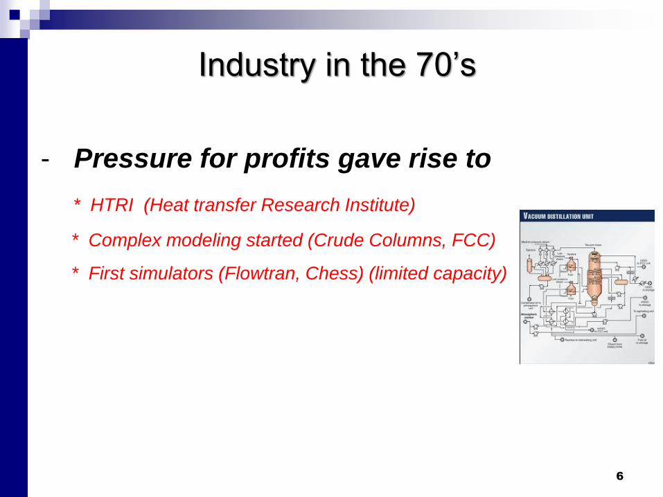
Industry in the 70’s
6
- Pressure for profits gave rise to
* HTRI (Heat transfer Research Institute)
* Complex modeling started (Crude Columns, FCC)
* First simulators (Flowtran, Chess) (limited capacity)

The engineering of the 80’s
7
- Conceptual Engineering is proposed:
Pinch design method .
• Process Engineering
* Still mostly equipment design- Trial and verify
* Flowsheeting emerges
- Process Synthesis
- Process Simulation

Industry in the 80’s
8
- Industry
* Simulators are used in Mainframe. No Graphical User interface
* Conceptual engineering is widespread known not widespread used.
* Process Operations Optimization Starts: Real time optimization
(Romeo, etc).
* Simulation goes commercial Aspentech and Simsci are formed

The engineering of the 90’s
9
- Desktop Computers * Simulation becomes pervasive
* Mathematical Programming Emerges
Heat exchanger network (Magnets, Synheat)
Complex Distillation (Petlyuk and other), Distillation networks, etc..
* Pinch technology shows some limitations but stays popular.
* Design for Flexibility and under uncertainty emerges (in Academia).
* The paradigm of simple models/decomposition reaches its limit.
* Supply Chain studies and planning models start

Industry in the 90’s
10
- Industry
* Simulators in PC are popular.
* Conceptual engineering is widespread known to exist but still not
widespread used.
* Process Operations Optimization becomes popular: Real time
optimization (Romeo, etc.) Data Reconciliation. Supply Chain
scheduling
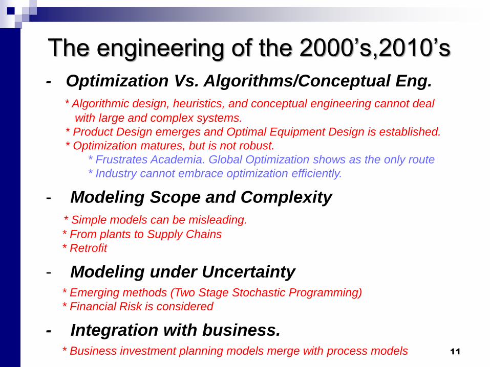
The engineering of the 2000’s,2010’s
11
- Optimization Vs. Algorithms/Conceptual Eng.
* Algorithmic design, heuristics, and conceptual engineering cannot deal
with large and complex systems.
* Product Design emerges and Optimal Equipment Design is established.
* Optimization matures, but is not robust.
* Frustrates Academia. Global Optimization shows as the only route
* Industry cannot embrace optimization efficiently.
- Modeling Scope and Complexity
* Simple models can be misleading.
* From plants to Supply Chains
* Retrofit
- Modeling under Uncertainty* Emerging methods (Two Stage Stochastic Programming)
* Financial Risk is considered
- Integration with business. * Business investment planning models merge with process models

Industry in the 2000’s
12
- Industry
* Scheduling of batch plants using Optimization methods makes its
debut.
* Long term Planning starts to be applied to real life problems
* Conceptual engineering continues to be widespread known to exist
and not widespread used.
* Process Operations Optimization becomes popular: Real time
optimization (Romeo, etc.) Data Reconciliation. Supply Chain
scheduling.

Product engineering (briefly)
13
Product Design
- Systematic Methods became popular in Academia only
recently
- Prevailing procedure both in industry and academia is
the STAGE GATE procedure.
- At stage One, many times new products are conceived
using the concept of “best product”, or what is
perceived as most needed..

Product engineering (briefly)
14
Product Design
- Alternative paradigms (Bagajewicz) propose to solve
stage one with more information about other stages
- Build preference functions based on product attributes
- For skin lotion: Smoothness, effectiveness, thickness, color…
- Connect product attributes to properties
- For skin lotion: viscosity, density, surface tension, etc.
- Connect properties to design
- For skin lotion: Composition, size, etc.
- Use pricing demand models
- Maximize NPV and simultaneously determine
- the product characteristics
- the portion of market demand to cover
- The selling price

Process engineering
15
Relationship of Academia with Industry
(Not all the time)

Process engineering
16
Relationship of Academia with Industry
It happens in real life !!!!
Letter to a VP:
We have so many irons in the fire at this point that we don’t have the capacity to review this opportunity. Thanks for thinking of us and giving us the opportunity to look at it, but we will have to pass at this time.
The University of Oklahoma has developed a new technology for xxxxxx . Basically, our technology reduces the cost by around 60%. Please let me know if you want to hear some more about it.
Answer

Process engineering
17
Relationship of Academia with Industry
However:
- Big companies keep looking for new technologies.
- But not in the traditional process engineering (with some notable exceptions such as catalysis)
- Effort is in nanotechnology, biomedicine, etc.

18
Teaching of Process Engineering
Engineering projects in capstone classes
Before the eighties
“Design a plant to produce chemical X, with capacity Y”
In the eighties
“Design a flexible plant to produce chemical X, with capacity Y,
capable of working in the given ranges of raw materials availability
and quality and product specifications”
In the nineties:
“Design a plant to produce chemical X, taking into account uncertain raw
materials and product prices, process parameters, raw material availability
and product demand, given the forecasts and determine when the plant
should be built as well as what expansions are needed”
Substitute “plant” by “network of processes” or by “product” and you have supply
chain problems or product engineering.

Process engineering
19
What is in the future?

The engineering of the XXI century
20
- Optimization more pervasive in Industry
What needs to happen?
* Graphic User Interface need to supplant programming language.
* Optimization needs to be robust and relatively fast
The only hope is global optimization.
* Computer clusters/ Supercomputers will be used in Industry
- Modeling under UncertaintyDeterministic Design using mean values abandoned. Academia will
lag behind again (books are outdated)
- Operations will automate (Smart Plants)Massive data handling. Strategic, tactical and real time decision
making intertwined.

The engineering of the XXI century
21
- Equipment Design
What needs to happen?
* Departure from Heuristics and migration to optimization models.
* Optimization –models need to be distributed.
- Methodology* Enumeration and Set trimming methods are alternatives
- Merging with Business and Finance Models* Especially in Scheduling & Operations/Investment Planning
models
* Several models addressing Uncertainty, Financial Risk, Contracts,
option contracts, etc. are already being generated and used

Parallel Processing-w/o Broadcasting
22
( )
. .
( , ) 0
0,1
i i
i
k s
i
Min c q f x
s t
q x k I
q i
+
1 2 3
11 12 13 21 22 23
0 1 2
Master Worker
3 Level 1
Processor Space Tree Space

Parallel Processing -Broadcasting
23
( )
. .
( , ) 0
0,1
i i
i
k s
i
Min c q f x
s t
q x k I
q i
+
Processor
0
Processor
1
Processor
2
Processor
(n-1)
Master Worker
Update of better cost
Broadcast Current Best Cost
Leader
………..

Financial Tools
24
Planning and scheduling as well as Design/Synthesis
under Uncertainty already exists.cing)
Add Financial Risk:
(Example is for Refinery Panning with Pricing)
GRM (Million US$)
-15 -10 -5 0 5 10 15 20 25 30 35 40
Ris
k
0.0
0.2
0.4
0.6
0.8
1.0
Deterministic
EGRM = 6.942 US$M
Stochastic
EGRM = 8.360 US$M
Deterministic (1 scenario)
GRM = 7.376 US$M
Financial Tools
- Value at Risk (VaR) &
Opportunity Value (OV)
- Downside Risk
- Standard Deviation (Less
and less used)

25
Future of Process & Product Design
Customer
-Needs
-Potential
Reactions
etc.
Chemical Supply Chain
-Modeled from the molecule to the
multi-company enterprise
- Using process Engineering Tools
- Integrating Business tools
Customer
-Demands
-Satisfaction
-Feedback
etc.
Management and Finances
-Working Capital Models
-Risk Analysis
-Budgeting Models
- etc.
Advertising
Human
Relations
(Labor)
Sociology
Psychology
Public Policy
Advertising

26
THE NEW EMERGING TREND OF INTEGRATION OF FINANCIAL
AND ENGINEERING TOOLS NEEDS TO BE REINFORCED WITH
NEW MODELS AND PROCEDURES.
MAXIMIZATION OF SHAREHOLDER VALUE IS THE ULTIMATE
OBJECTIVE.
TWO-STAGE STOCHASTIC PROGRAMMING IS ADVOCATED TO
BE THE INTEGRATING TOOL.
RISK IN DESIGN AND DECISION MAKING (SCHEDULING,
PLANNING, ETC.) SHOULD BE MANAGED USING A
MULTIOBJETIVE FRAMEWORK.
CONTRACTS, OPTIONS, PRICING, ETC. CAN BE EASILY ADDED.
Future of Process & Product Design

27
OPTIMIZATION WILL BECOME PERVASIVE.
OUR DESIRE TO BE AS ACCURATE AS POSSIBLE IN OBTAINING
THE BEST RESULT WILL TILT THE TOOL TOWARDS
MATHEMATICAL PROGRAMMING
RIGOROUS GLOBAL OPTIMIZATION WILL BECOME THE TOOL
OF CHOICE
SUPERCOMPUTERS OR COMPUTING IN THE CLOUD MIMICKING
PARALLEL COMPUTATION WILL BE USED
CONCEPTUAL ENGINEERING WILL FADE AS A TOOL FOR
DESIGN AND WILL REMAIN AS A TOOL FOR QUALITATIVE
UNDERSTANDING (As McCabe Thiele is today for distillation).
Future of Process & Product Design
28
Current “Hot” Issues
• Mathematical Optimization vs. Conceptual Engineering
• Individual Equipment & Plants
• Supply Chains
• Deterministic Design vs. Design under Uncertainty
• Relationship with Industry
• Level of Detail in models
• Parallel Processing
• New Solution Procedures: Enumeration & Set Trimming

Message
29
- Do not simplify models. Actually, do the opposite
- Decompose only if needed (Descartes advice)
- Use robust global optimization when possible
- Incorporate Uncertainty
- Consider retrofit models
- Continue to pursue integration with business tools
- Integrate product, process and business.

30
André L. H. Costaa,*, Miguel J. Bagajewiczb
aRio de Janeiro State University (UERJ)bSchool of Chemical, Biological and Materials Engineering, University of Oklahoma

31

OUTLINE
32
• HEURISTICS-BASED EQUIPMENT DESIGN IS
SUBOPTIMAL AT BEST
• PROPERLY REFORMULATED MINLP IS NEEDED
• GLOBAL OPTIMALITY MAKES A DIFFERENCE
• ALTERNATIVES TO MINLP: ENUMERATION AND SET
TRIMMING
• DISTRIBUTED (MORE COMPLEX) MODELS ARE THE
BEST ANSWER. THEY MODIFY THE SYSTEM
• PARALELL COMPUTING IS IN OUR FUTURE
IECR 100 Anniversary article (under revision)

INTRODUCTION
33
Significant advances were made by the PSE
community in the use of optimization models
and solution algorithms.
However, basic equipment design procedures
still are heuristics-based.

INTRODUCTION
34
Indeed, basic equipment design heuristics
procedures use Trial and verification
• Propose the value of some parameters or
geometrical variable.
• Calculate the rest of the variables using heuristics
• If the solution is viable stop. Otherwise correct.
It is still the recommended method in
most texts

INTRODUCTION
35
QUESTIONS:
• What are the reasons that restrain the
utilization of mathematical programming
for the solution of equipment design
problems?
• How can these obstacles be removed?

HEURISTICS-BASED PROCEDURES
36
Shell-and-Tube Heat Exchanger Design
1) Propose a heat exchanger type
2) Propose a value of U and obtain Area
3) Propose Shell & tubes D, Length, baffles, # passes
4) Check if the design is acceptable (Ucalc>Uassumed)
5) If the solution is OK, stop
6) Otherwise, propose modifications (step 3 or step 2)
We call this “Trial and Verification”

HEURISTICS-BASED PROCEDURES
37
Shell-and-Tube Heat Exchanger Design
Trial and Verification is:
• Strongly based on human intervention
• Experienced designers are needed
• Not even locally optimal.

HEURISTICS-BASED PROCEDURES
38
Similar design approaches:
- Vertical and horizontal flash-units;
- Distillation column tray design.
- etc.

OPTIMIZATION MODELS
39
Shell-and-Tube Heat Exchanger Design
In the last 10-15 years, a limited number
of papers address the use of
mathematical programming for the design
of heat exchangers.

OPTIMIZATION MODELS
40
Shell-and-Tube Heat Exchanger Design
EVOLUTION
Earlier approaches: NLP
Last 10 years: Non-Convex MINLP

OPTIMIZATION MODELS
41
Shell-and-Tube Heat Exchanger Design
Limitations:
➔ Lack of robustness of NLP and MINLP models:
- Convergence problems
- Multiple local optima

OPTIMIZATION MODELS
42
Shell-and-Tube Heat Exchanger Design
Observation :
➔ Models are based on analytical solutions
- LMTD method with correction factors
➔ Not looking at distributed states along the
exchanger

43
These challenges in heat exchanger design have
been and are addressed in our international
research group as follows:
OPTIMIZATION MODELS
▪ Problem reformulation
▪ Alternative procedures to Mathematical Programming
▪ Distributed Models

44
Several design variables are only available
in discrete values:
- Commercial alternatives, e.g.:
Tube diameter: ¾ in, 1 in, 1 ¼ in, etc.
- Physical nature, e.g.:
Number of baffles: 1, 2, 3, etc.
REFORMULATION

45
Typical tube-side heat transfer coefficient
x
σ𝑠𝑑𝑚𝑖𝑛𝑠𝑑𝑚𝑎𝑥 𝑦𝑑𝑠𝑑 = 1
Nt𝑡 = σ𝑠𝑑=1𝑠𝑑𝑚𝑎𝑥 𝑝𝑁𝑡𝑡𝑠𝑁𝑡𝑡 y𝑁𝑡𝑡𝑠𝑁𝑡𝑡
σ𝑠𝑁𝑡𝑡𝑚𝑖𝑛𝑠𝑁𝑡𝑡𝑚𝑎𝑥 𝑦𝑁𝑡𝑡𝑠𝑁𝑡𝑡 = 1
REFORMULATION
ℎ𝑡 =0.023 𝑅𝑒𝑡0.8 𝑃𝑟𝑡𝑛 𝑘𝑡
𝑑𝑡𝑖
𝑑𝑡𝑖 = σ𝑠𝑑=1𝑠𝑑𝑚𝑎𝑥𝑝𝑑𝑡𝑖𝑠𝑑 𝑦𝑑𝑠𝑑
(
2
)
𝑅𝑒𝑡 =𝑑𝑡𝑖 𝑣 ෞ𝜌𝑡
ෝ𝜇𝑡=
4 ෞ𝑚𝑡
𝑁𝑡𝑡 𝜋 ෝ𝜇𝑡 𝑑𝑡𝑖
Heat transfer coefficient
Reynolds number
Diameter in terms of discrete options
Number of tubes is discrete
THE OVERALL MODEL IS A NONCONVEX MINLP
We write

46
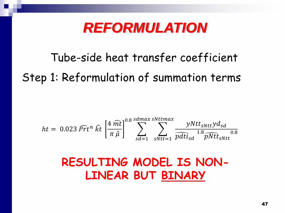
Tube-side heat transfer coefficient
Step 1: Reformulation of summation terms
REFORMULATION
ℎ𝑡 =0.023 𝑅𝑒𝑡0.8 𝑃𝑟𝑡𝑛 𝑘𝑡
𝑑𝑡𝑖
ℎ𝑡 =0.023𝑃𝑟𝑡𝑛𝑘𝑡
(σ𝑠𝑑𝑚𝑖𝑛𝑠𝑑𝑚𝑎𝑥 𝑝𝑑𝑡𝑖𝑠𝑑 𝑦𝑑𝑠𝑑)
1.8
4ෞ𝑚𝑡
𝜋 ෝ𝜇𝑡 σ𝑠𝑑=1𝑠𝑑𝑚𝑎𝑥 𝑝𝑁𝑡𝑡𝑠𝑁𝑡𝑡 y𝑁𝑡𝑡𝑠𝑁𝑡𝑡
0.8
ℎ𝑡 = 0.023 𝑃𝑟𝑡𝑛 𝑘𝑡4 ෞ𝑚𝑡
𝜋 ෝ𝜇𝑡
0.8
𝑠𝑑=1
𝑠𝑑𝑚𝑎𝑥
𝑠𝑁𝑡𝑡=1
𝑠𝑁𝑡𝑡𝑚𝑎𝑥𝑦𝑁𝑡𝑡𝑠𝑁𝑡𝑡𝑦𝑑𝑠𝑑
𝑝𝑑𝑡𝑖𝑠𝑑1.8𝑝𝑁𝑡𝑡𝑠𝑁𝑡𝑡
0.8
This is the key step
47
Tube-side heat transfer coefficient
Step 1: Reformulation of summation terms
REFORMULATION
ℎ𝑡 = 0.023 𝑃𝑟𝑡𝑛 𝑘𝑡4 ෞ𝑚𝑡
𝜋 Ƹ𝜇
0.8
𝑠𝑑=1
𝑠𝑑𝑚𝑎𝑥
𝑠𝑁𝑡𝑡=1
𝑠𝑁𝑡𝑡𝑚𝑎𝑥𝑦𝑁𝑡𝑡𝑠𝑁𝑡𝑡𝑦𝑑𝑠𝑑
𝑝𝑑𝑡𝑖𝑠𝑑1.8𝑝𝑁𝑡𝑡𝑠𝑁𝑡𝑡
0.8
RESULTING MODEL IS NON-LINEAR BUT BINARY

48
Tube-side heat transfer coefficient
Step 2: Conversion to a linear model
REFORMULATION
ℎ𝑡 = 0.023 𝑃𝑟𝑡𝑛 𝑘𝑡4 ෞ𝑚𝑡
𝜋 Ƹ𝜇
0.8
𝑠𝑑=1
𝑠𝑑𝑚𝑎𝑥
𝑠𝑁𝑡𝑡=1
𝑠𝑁𝑡𝑡𝑚𝑎𝑥𝑦𝑁𝑡𝑡𝑠𝑁𝑡𝑡𝑦𝑑𝑠𝑑
𝑝𝑑𝑡𝑖𝑠𝑑1.8𝑝𝑁𝑡𝑡𝑠𝑁𝑡𝑡
0.8
ℎ𝑡 = 0.023 𝑃𝑟𝑡𝑛 𝑘𝑡4 ෞ𝑚𝑡
𝜋 Ƹ𝜇
0.8
𝑠𝑑=1
𝑠𝑑𝑚𝑎𝑥
𝑠𝑁𝑡𝑡=1
𝑠𝑁𝑡𝑡𝑚𝑎𝑥𝑤𝑦𝑁𝑡𝑡𝑑𝑠𝑁𝑡𝑡,𝑠𝑑
𝑝𝑑𝑡𝑖𝑠𝑑1.8𝑝𝑁𝑡𝑡𝑠𝑁𝑡𝑡
0.8
𝑤𝑦𝑁𝑡𝑡𝑑𝑠𝑁𝑡𝑡,𝑠𝑑 ≤ 𝑦𝑁𝑡𝑡𝑠𝑁𝑡𝑡𝑤𝑦𝑁𝑡𝑡𝑑𝑠𝑁𝑡𝑡,𝑠𝑑 ≤ 𝑦𝑑𝑡𝑠𝑑𝑤𝑦𝑁𝑡𝑡𝑑𝑠𝑁𝑡𝑡,𝑠𝑑 ≥ 𝑦𝑑𝑡𝑠𝑑 + 𝑦𝑁𝑡𝑡𝑠𝑁𝑡𝑡-1
RESULTING MODEL IS MIL OR MILDLY MINL

49
Our experience using this approach:
- Shell-and tube heat exchanger (Kern)Gonçalves et al. (2017)
REFORMULATION

50
Our experience using this approach:
- Shell-and tube heat exchanger (Kern) (AICHE J.)
- Shell-and tube heat exchanger (Bell-Delaware) (AICHE J.)
- Shell-and tube heat exchanger / Fouling Modeling (AICHE J.)
- Air coolers with fixed air flow rate. (AICHE J.)
- Air coolers paired with fans. (Advanced Thermal Engineering).
- Plate heat exchangers (ESCAPE)
- Double pipe heat exchangers (ESCAPE)
- Flash vessels’ tray design (To be submitted)
- Separation Colum Tray Design (In Preparation)
REFORMULATION

IMPORTANCE
– CONVERSION OF HIGHLY NON-LINEAR
MODELS TO LINEAR OR MILDLY LINEAR
MODELS RENDERS
❑ Global solutions
❑ Robustness (Solution is always obtained)
❑ Easy insertion in other models (i.e. Heat exchanger
Network Synthesis with simultaneous HEX design51

DEPARTURE FROM MINLP
– Nomenclature issue
o Mixed integer nonlinear models
(MINLM) are the minimization problem
o MINLP is one procedure to solve a
MINLM (P stands for “programming”)
52

DEPARTURE FROM MINLP
– OTHER PROCEDURES TO SOLVE A MINLM
o Smart Enumeration
o Set Trimming
o Combination of both and eventually
followed by a MINLP
53

Heat Exchanger Design (TAC optimization)
• Consider discrete geometric parameters
- Shell and Tube diameters (Do and do)
- Length (L)
- Number of passes (Np)
- Number of tubes per pass (Ntp)
- Number of baffles (Nb)
- Each combination (Do , do, L , Np, Ntp , Nb) Area (A)
SMART ENUMERATION
54

SMART ENUMERATION
List all (M) exchangers in increasing order by AREA
- (Do,i , do,j, Lk, Np, Ntp , Nb) A1
- (Do,i , do,j, Lk, Np, Ntp , Nb) A2
- ....
- (Do,i , do,j, Lk, Np, Ntp , Nb) AM
55

SMART ENUMERATION
Find first feasible Exchanger
- A1 infeasible
- A2 infeasible
- ....
- As feasible
- Calculate COST (For minimum area problem, this is the optimum)
56

SMART ENUMERATION
Inspect using Updating & Stopping criteria
First feasible exchanger is the Incumbent Exchanger.
Updating
If COST(An)< COST of Incumbent An is now
the new Incumbent.
Stopping
If COST(An)< Incumbent Area Cost Stop
(A lower cost will never be found)
57

Heat Exchanger Design with fouling modeling
SET TRIMMING
Geometrically
unfeasible
Exchangers
Geometrically
Feasible
ExchangersAll Exchangers (S)
Geometrically
unfeasible
Not
Viable
clean
Viable clean
58

SET TRIMMING
Geometrically
unfeasible
Not
Viable
clean
Viable cleanViable
dirty
Area >
A of Best
Clean
Area <
Area of
Best
Clean
Not
Viable
clean
Viable
clean
Heat Exchanger Design with fouling modeling
Geometrically
unfeasible
Not
viable
clean Viable clean
Geometrically
unfeasible
Best clean
59

SET TRIMMING
Area < Area of Best
Clean + Viable for
Rf=Rfmax
Geometrically
unfeasible
Viable dirty,
but not viable
for Rf=Rfmax
Area >
A of Best
Clean
Geometrically
unfeasible
Area < Area of Best
Clean + Viable for
Rf=Rfmax
Area >
A of Best
Clean
Area >
“cross”
Area <
“cross”
Heat Exchanger Design with fouling modeling
Area >
A of Best
Clean
Area <
Area of
Best
Clean
Not
Viable
clean
Viable
clean
60
Not
Viable
clean
Not
Viable
clean
Viable
clean
Viable
clean
Geometrically
unfeasible
Best
OPT

DEPARTURE FROM MINLP
Enumeration and/or Set Trimming:
• Render GLOBALLY OPTIMAL SOLUTIONS
• Are not prohibitive computationally
Example: Air cooler design
61
Globally Optimal Design of Air Coolers Considering Fan Performance. de Carvalho et al. (Submitted)
Number of geometry options = 3,333,960.
Set trimming : 3,540 seconds
Smart Enumeration: 1,609 Using Matlab
MINLP Local and Global
Solvers fail to solve!!!

DISTRIBUTED MODELS
– Moving away from simplified models based
on analytical solutions (e.g. LMTD method)
– Use of conservation equations and state
evaluation locally
62

DISTRIBUTED MODELS
Design of double pipe heat exchangers
63

DISTRIBUTED MODELS
Design of double pipe heat exchangers
Rigorous
Average
Conservative
64
Larger!!!
Too large!!!

DISTRIBUTED MODELS
We are now investigating local models applied to
the design of air coolers
𝑈𝜋𝐷𝑡𝑒 𝑁𝑡𝑟 𝑇ℎ − 𝑇𝑐 =ෝ𝑚ℎ
𝑁𝑟𝐶𝑝ℎ
𝑑𝑇ℎ
𝑑𝑦
𝑈𝑟,𝑠,𝑗𝜋𝐷𝑡𝑒 𝑇ℎ𝑟,𝑠,𝑗 −𝑇𝑐𝑟,𝑠,𝑗 + 𝑇𝑐𝑟+1,𝑠,𝑗
2=ෝ𝑚ℎ
𝑁𝑟𝐶𝑝ℎ𝑟,𝑠,𝑗
𝑇ℎ𝑟,𝑠,𝑗+1 − 𝑇ℎ𝑗−1
𝛿𝑟,𝑠,𝑗
W
FOLGA
FOLGA
H
x
z
AR FRIO
AR QUENTE
De
Df
X
z
x
65

DISTRIBUTED MODELSParaphrasing Decartes:
“Simplify and Decompose every engineering problem in as many
parts as needed to solve it”
- Before we had computers we did this. It was right!!!
- When we got computers we still insisted with “simple” and
“Conceptual”. It is not working.
- Mathematical Modeling is prevailing. More complex modeling gives
different answers.
66
IT IS TIME WE MOVE IN THE OTHER DIRECTION
OF MORE COMPLEX MODELS

Parallel Processing-w/o Broadcasting
67
( )
. .
( , ) 0
0,1
i i
i
k s
i
Min c q f x
s t
q x k I
q i
+
1 2 3
11 12 13 21 22 23
0 1 2
Master Worker
3 Level 1
Processor Space Tree Space
Air cooler design: 24 seconds using 25processors

Parallel Processing -Broadcasting
68
( )
. .
( , ) 0
0,1
i i
i
k s
i
Min c q f x
s t
q x k I
q i
+
Processor
0
Processor
1
Processor
2
Processor
(n-1)
Master Worker
Update of better cost
Broadcast Current Best Cost
Leader
………..
Parallel Processing
69
It ameliorates and improves upon two current
problems
▪ Computational time
▪ Problem Size (One can partition the Feasible
region)

FUTURE WORK
70
• Medium term objectives:
– Put together units of similar kind:
HEN
– Put together models of units of different kinds:
+ Distillation Column
+ Condenser
+ Reboiler
In preparation using Enumeration and MIL models

OUR NIRVANA (and yours)
71
THINK OF
SIMPLIFY AND DECOMPOSE AS NEEDED
(Decartes & Art Westerberg dixit)
A WHOLE FLOWSHEET-Distributed equipment models
- Globally optimal- Under Uncertainty
- Multipurpose and Multiperiod- Financial Risk Managed
- etc.

CONCLUSIONS
72
• Equipment design problems:
Traditional trial-and-verification approach
• Limitations of current PSE tools:
- Lack of robustness & Oversimplified models
• Proposed:
- Reformulation simplifies models
- Use Smart Enumeration & Set Trimming + MINLP
- Distributed Models (Do not simplify. Go complex)
- Parallel Computing is the answer to memory & time
OPTIMIZE FIRST!! (Larry Biegler dixit)