migration of satellite receiving stations to the new meteorological
TRANSCRIPT
MIGRATION OF SATELLITE RECEIVING STATIONS TO THE NEW METEOROLOGICAL SATELLITE DIGITAL DATA
BROADCAST SERVICES
2001
SAT-27
TECHNICAL DOCUMENT
WMO/TD No. 1057

- i -
TABLE OF CONTENTS
Page INTRODUCTION .............................................................................................................................. 1 1. BACKGROUND .................................................................................................................. 1 1.1 Automatic Picture Transmission (APT) ................................................................................1 1.2 Weather Facsimilie (WEFAX) ..............................................................................................2 2. NEW SYSTEMS.................................................................................................................. 2 2.1 Low Rate Information Transmission (LRIT) .........................................................................3 2.2 Low Rate Picture Transmission (LRPT)...............................................................................4 3. COMMUNICATION MODEL ............................................................................................... 4 3.1 Engineering Information.......................................................................................................4 3.2 Definition of ISO Standard Layers for LRIT and LRPT ........................................................6 3.2.1 Low Rate Information Transmission (LRIT) ........................................................................ 6 3.2.2 Low Rate Picture Transmission (LRPT).............................................................................. 9 3.2.3 Applicability of Standards.................................................................................................. 12 3.2.4 Additional Information ....................................................................................................... 12 4. OPERATIONAL INFORMATION ...................................................................................... 13 4.1 Low Rate Information Transmission (LRIT) .......................................................................13 4.1.1 Accuracy ........................................................................................................................... 13 4.1.2 Examples of Products ....................................................................................................... 13 4.2.1 Accuracy ........................................................................................................................... 15 4.2.2 Available Data................................................................................................................... 17 4.3 High Rate Information Transmission (HRIT) ......................................................................17 4.4 Advanced High Rate Picture Transmission (AHRPT) ........................................................17 4.5 Other Services ...................................................................................................................17 4.5.1 Internet .............................................................................................................................. 17 5. AVAILABILITY OF COMMERCIAL RECEIVING STATIONS FOR LRIT/LRPT................ 17 6. REFERENCES.................................................................................................................. 18 6.1 Documents .........................................................................................................................18 6.2 Postal Addresses and Websites ........................................................................................18 6.3 Other Useful Websites ...................................................................................................... 19
TABLE OF FIGURES FIGURE 3.1 Communication Model .......................................................................................... 5 FIGURE 3.2 Overall Data Flow.................................................................................................. 7 FIGURE 3.3 Source Packet Structure ....................................................................................... 9 FIGURE 3.4 CVCDU Structure................................................................................................ 10 FIGURE 3.5 Modulator Block Diagram.................................................................................... 11 FIGURE 3.6 Interleaver Block Diagram................................................................................... 11 FIGURE 3.7 Frame Structure .................................................................................................. 11 FIGURE 3.8 QPSK Constellation Diagram.............................................................................. 12 FIGURE 4.1 East Asia Polar Stereographic ............................................................................ 14
INTRODUCTION This document is written to enable WMO Members to plan and execute the transition from the current analogue direct transmissions from meteorological satellites to the various types of digital data transmissions that will replace those older transmissions early in the new millennium. The document is divided into six sections as follows: Section 1: Background Section 2: New Systems Section 3: Engineering Information Section 4: Operational Information Section 5: Availability of Commercial Products for LRIT/LRPT Section 6: Reference Publications 1. BACKGROUND Since the launch of the TIROS I weather satellite on 1 April 1960, meteorologists have found ever increasing uses for observations taken from space. Initially, all data were stored on board and transmitted from the spacecraft to ground over a few ground stations. Because available communications links were limited in bandwidth, initial efforts to share this new data were limited to products with greatly reduced content such as nephanalyses of cloud boundaries. Such products could be disseminated over telephone lines using early facsimile techniques. 1.1 Automatic Picture Transmission (APT) In December 1963, however, the satellite TIROS VIII was launched carrying a new experimental type of space sensor. The slow scan vidicon cameras on TIROS VIII were designed to make a snapshot of the Earth and then read out the image stored on the face of the vidicon tube over a long period. This meant that the rate at which data were transmitted to the ground was very low. Because of this, it was possible to receive the signal and reproduce the image with very unsophisticated equipment. Because the imagery was recorded and transmitted to the ground automatically, this system was named Automatic Picture Transmission (APT). APT transmissions became routine beginning with the launch of ESSA 2 on 28 February 1966. Within a few years, the METEOR series of satellites began a complementary service, transmitting visible imagery of the Earth’s cloud cover in a similar format. In addition, these polar orbiting satellites were now in so-called sun synchronous orbits, meaning that they produced imagery with a relatively constant sun angle. This also meant that they crossed over a fixed ground station at about the same time each day, making it easier to schedule, capture, and use the data in heavily schedule-oriented weather services. While APT remained the standard direct readout of operational TIROS and METEOR satellites throughout the decade of the sixties, the experimental NIMBUS satellites carried new types of sensors. These new sensors produced images of the Earth in the infrared portion of the spectrum and gathered data about the temperature structure of the atmosphere using infrared radiometers. With the launch of ITOS 1 in January 1970, these IR sensors made their first appearance on operational satellites and for the first time, APT signals contained multispectral images. The sensor was named the Scanning Radiometer (SR) and made radiometric measurements in both the visible and infrared portions of the spectrum. In order to accommodate these new transmissions, however, it was necessary for users to modify their ground equipment. This was because the breaks between successive lines of the new images were longer. Hence the devices used to produce images were required to skip these breaks and “draw” only the part of each line containing imagery information. This was the first of several major changes in the parameters of APT transmissions. Satellite operators worked with users around the world to communicate the necessary changes as well as mechanisms for making them.

- 2 -
With the launch of the NOAA-2 satellite on 15 October 1972, a new sensor entered the operational inventory. The Vertical Temperature Profile Radiometer (VTPR) made its appearance as the first operational temperature sounder from space. While crude by today’s standards, VTPR was effective enough that it was soon added to the data sources transmitted directly to Earth for use by so-called “direct readout” users. The transmission was named Direct Sounder Broadcast (DSB) and was used by universities and amateur radio operators along with the multispectral APT imagery. The major difference between DSB and APT was that the DSB data were encoded in digital form because sounding data was of very little use unless the accuracy of the data was preserved. The users of APT imagery, despite its lack of accurate calibration, were able to make many ingenious uses of the qualitative imagery, which it produced. But the users of DSB required reasonable knowledge of the absolute values of the infrared radiances being measured by the VTPR. The use of the DSB data, however, required the availability of fairly high-powered computers so that APT remained the most used direct broadcast service. Although a number of incremental improvements were made in the APT service throughout the seventies, eighties, and nineties, the basic analogue service remained relatively unchanged until the present time. The sensor from which the APT signals are derived has evolved from the simple two-channel SR to the current Advanced Very High Resolution Radiometer (AVHRR). This necessitated a signal processor on board the satellite to reduce the complexity of the AVHRR data to a data stream that could be transmitted via the APT communications channel. For example, it is necessary to select two of the AVHRR’s six infrared channels for APT transmission. The remainder of the data is not available except via the higher data rate, and the considerably more complicated HRPT transmission. 1.2 Weather Facsimilie (WEFAX) With the launch of the first operational geostationary weather satellites in the middle of the decade of the seventies, a new source of data became available in the form of imagery taken from the vantage point of a platform which remained quasi-stationary in an Earth frame of reference. For the first time views of developing systems on a scale which allowed monitoring of thunderstorms and other events on a sub-synoptic scale became available. Again, the data were read out by ground stations that quickly became overwhelmed by the sheer volume of data (300 megabytes per full disk image). In order to make these images available to users within sight of the satellite, the WEFAX system was inaugurated. WEFAX (a contraction of Weather Facsimile) was a low data rate, analogue stream that provided to users with moderate priced ground stations a means of tapping the geostationary satellites’ databases. However, the WEFAX system did not employ a special processor on board the satellite. Instead, since the satellite is always in sight of the ground station, the raw data are received and processed on the ground. Then the specially processed data are retransmitted to the satellite where a dedicated radio transponder sends these data to users. WEFAX transmissions have not changed in either format or accuracy since their inception in 1974. Information and formats for WEFAX are readily available from the operators. For postal and Internet addresses, see sections 6.2. 2. NEW SYSTEMS As the Global Observing System (GOS) enters a new millennium, the Coordination Group for Meteorological Satellites (CGMS), representing all operational satellite operators, have agreed to improve the APT and WEFAX systems by converting them to all-digital systems with increased precision, improved resolution imagery, and increased capability for producing quantitative products (e.g., sea-surface temperature). Table 1 shows the services, replacement services, and planned conversion dates as reported at the Twenty-eighth session of CGMS held in October 2000.

- 3 -
TABLE 1 SCHEDULE OF NEW SERVICE INTRODUCTION
(as reported at the Twenty eighth session of CGMS held in October 2000)
Operator/satellite Start When Discontinue When Remarks
EUMETSAT/Meteosat LRIT 2002 WEFAX 2003 Launch of MSG-1
EUMETSAT/Metop [0930 LST Overpass]
LRPT 2006 Initial launch of METOP
Japan/GMS/MTSAT LRIT 2003 WEFAX 2005 Launch of MTSAT-1R
Russian Federation/ Meteor LRPT 2003 TBD Launch of Meteor 3M N2
Russian Federation/ Electro LRIT TDB WEFAX TBD Launch of Electro 3
China/FY-1 NO LOW RESOLUTION
China/FY-2 LRIT 2003 WEFAX TBD Launch of FY-2C
USA/NOAA-N’ APT 2011 Last of NOAA series
USA/NPOESS [0530 and 1330 LST Overpass]
TBD TBD TBD
USA/GOES LRIT 2002 WEFAX TBD GOES-East
NOTES to Table 1: (1) The above “Start” and “Discontinue” dates are approximate because they depend on launch dates which themselves depend upon need dates. CGMS operators have agreed that the older, analogue services will only be discontinued, when possible, following a minimum three-year overlap period to allow adequate time for users to convert to the new system; (2) Further details and up-to-date information can be obtained at the WMO web site: http://www.wmo.ch/ [Click on “WMO Satellite Activities” and then on “LRIT/LRPT Transition.”]; (3) Overpass times are for the period following the launch of Metop-1 and NPOESS-1. Prior to that time, NOAA Satellites provide service with 07:30 and 13:30 overpass times. The EUMETSAT Polar Series, designated METOP in Table 1, will replace the 07:30 NOAA satellite. 2.1 Low Rate Information Transmission (LRIT) This new service will be operated by the next generation of geostationary orbit meteorological satellites for transmissions to low cost user stations. This service will gradually replace the WEFAX service as indicated in Table 1 and will serve a similar user community. Information will be received via Low Rate User Stations (LRUS). User station antennae will have diameters around 1.8 m and the figure of merit for LRUS will be 5-6 dB/K depending on the user station location. Transmissions of LRIT will be in the sub-band 1690 – 1698 MHz with centre frequencies around 1691 MHz. The bandwidth will be up to 2 MHz. Note that the first service under LRIT will be by Meteosat Second Generation-1 in the European/African region, in the year 2002.
- 4 -
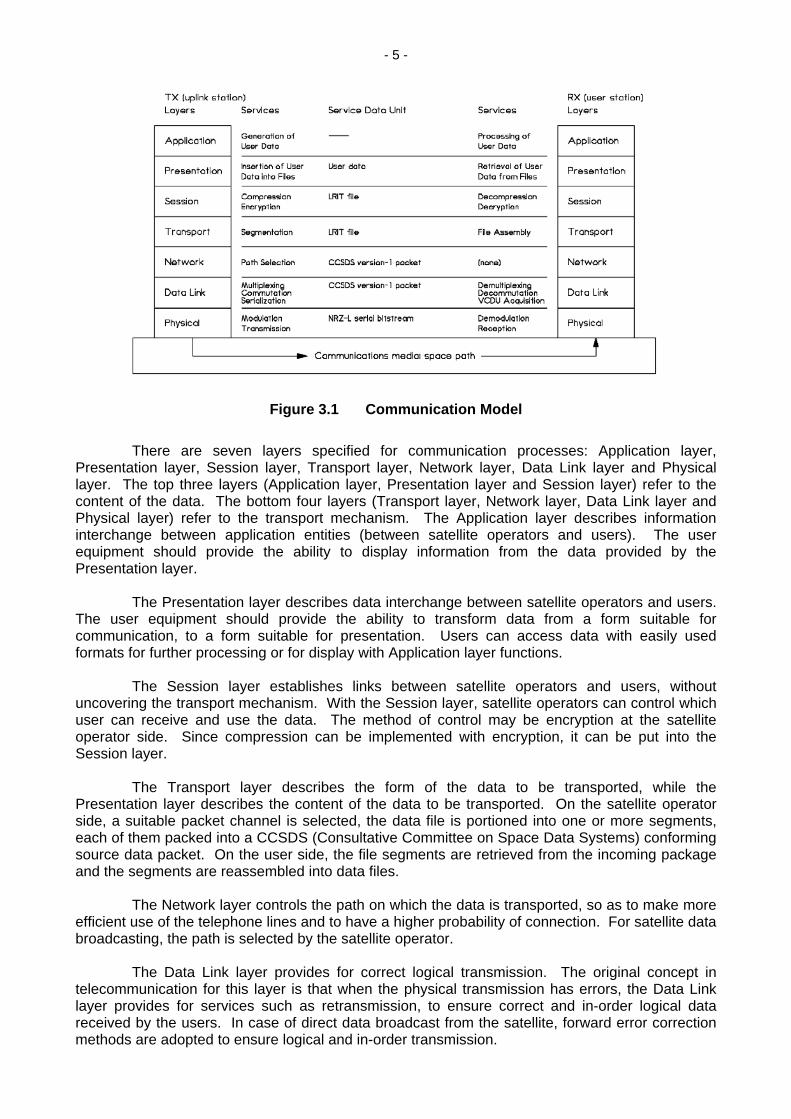
2.2 Low Rate Picture Transmission (LRPT) This service is planned to replace the APT transmissions from polar orbit satellites. It will be based on digital transmission schemes and will make use of the same frequency bands as registered for APT. The bandwidth will be 150 kHz. The service commencement dates will be as shown in Table 1. With the introduction of LRPT, information from other polar sensors, most notably from the temperature sounder will now be available in the LRPT data stream. This will replace the current Direct Sounder Broadcast. Other data from the polar satellites may be included and this will be announced through appropriate media and in a timely fashion through WMO channels, including the "Satellite" web page. First service of LRPT will be by Metop-1 and Meteor 3M N2, beginning in 2003. Because of the much later introduction of LRPT by NPOESS, there will be an extended period during which APT will remain available from some satellites while LRPT will be simultaneously available from others. 3. COMMUNICATION MODEL 3.1 Engineering Information This section is written to acquaint the user with the International Organization for Standardization (ISO) Standard 7498 from which the specifications for both LRIT and LRPT are derived. Although CGMS members have tried to maintain commonality between the two services to the greatest extent possible, there are some necessary differences. The global reference documents for the two services are as follows: For LRIT: LRIT/HRIT Global Specification Doc. No: CGMS-03 dated August 1999 For LRPT: LRPT/AHRPT Global Specification Doc. No: CGMS-04 dated October 1998 These specifications may be obtained from the CGMS secretariat postal address or from the WMO web site at the URL specified in section 6.2 of this document. Detailed mission specific specifications are available for each mission. LRIT mission specific documents are listed in section 6.1 and are available from the WMO, EUMETSAT and/or JMA by post from the addresses or respective web sites given section 6.2. In order to specify the LRIT/LRPT format, the ISO standard 7498 (OSI reference model) is used as a basis. LRIT/LRPT is mapped onto seven layers, conceptually similar to the OSI reference model. Figure 3.1 depicts application of the reference model to LRIT. Because LRIT is a dissemination mission there is a unidirectional flow of information from a transmission system (denoted as TX) to a reception system (denoted as RX). In the physical representation the transmission system is the central LRIT uplink station and the reception system is one LRIT user station. In the case of LRPT, the spacecraft (and its data processing system) constitutes the transmission system and the ground receiving system is denoted as RX.
- 5 -
Figure 3.1 Communication Model There are seven layers specified for communication processes: Application layer, Presentation layer, Session layer, Transport layer, Network layer, Data Link layer and Physical layer. The top three layers (Application layer, Presentation layer and Session layer) refer to the content of the data. The bottom four layers (Transport layer, Network layer, Data Link layer and Physical layer) refer to the transport mechanism. The Application layer describes information interchange between application entities (between satellite operators and users). The user equipment should provide the ability to display information from the data provided by the Presentation layer. The Presentation layer describes data interchange between satellite operators and users. The user equipment should provide the ability to transform data from a form suitable for communication, to a form suitable for presentation. Users can access data with easily used formats for further processing or for display with Application layer functions. The Session layer establishes links between satellite operators and users, without uncovering the transport mechanism. With the Session layer, satellite operators can control which user can receive and use the data. The method of control may be encryption at the satellite operator side. Since compression can be implemented with encryption, it can be put into the Session layer. The Transport layer describes the form of the data to be transported, while the Presentation layer describes the content of the data to be transported. On the satellite operator side, a suitable packet channel is selected, the data file is portioned into one or more segments, each of them packed into a CCSDS (Consultative Committee on Space Data Systems) conforming source data packet. On the user side, the file segments are retrieved from the incoming package and the segments are reassembled into data files. The Network layer controls the path on which the data is transported, so as to make more efficient use of the telephone lines and to have a higher probability of connection. For satellite data broadcasting, the path is selected by the satellite operator. The Data Link layer provides for correct logical transmission. The original concept in telecommunication for this layer is that when the physical transmission has errors, the Data Link layer provides for services such as retransmission, to ensure correct and in-order logical data received by the users. In case of direct data broadcast from the satellite, forward error correction methods are adopted to ensure logical and in-order transmission.
- 6 -
The Physical layer performs the transfer of the serial bit stream from the satellite operator to the users. On the user side, the modulated transmission carrier signal is demodulated to form the serial bit stream. Below the communication system there is the communications media, which is the space path from the uplink station towards the user station including the transponder functionality of the spacecraft. For each of the communications layers a service data unit (SDU) can be defined which is the data structure appearing at the top of that layer. Additionally, for each layer there is a set of services to be named. In this special application, the TX services for one layer receive the related SDU as input, and the RX services generate the related SDU as output. LRIT/LRPT provides means for packetized communication. Several application processes on the TX side may send data, virtually parallel, to their partners on the RX side. Its application process identifier (APID) identifies each application process. Figure 3.2 shows the generalized situation. For LRIT/LRPT, layers 1...6 are specified. 3.2 Definition of ISO Standard Layers for LRIT and LRPT A very brief overview of the data formatting standards of the ISO as employed for LRIT and LRPT is given in this section. It is not intended to be exhaustive, but merely to act as an indication to non-technical readers of the flexibility of the methods to be employed. In each case, however, direction is given as to the availability of more detailed information when required. 3.2.1 Low Rate Information Transmission (LRIT) 3.2.1.1 Application layer The application layer describes the information interchange between application entities. Examples for application entities on the TX side could be: - a process generating image products from remote sensing data, - a spacecraft operator issuing an administrative message, - a process generating meteorological bulletins. On the RX side one could find possible application entities in: - a process visualising image loops, - a user station operator reading an administrative message, - an application program processing meteorological bulletins. There is no service data unit for the application layer.

- 7 -
Figure 3.2 Overall Data Flow
3.2.1.2 Presentation layer The service data unit for the Presentation layer is the user data (e.g., image product, administrative message, meteorological bulletin), which it is receiving from or sending to the Application layer. Within the Presentation layer the information is transformed from a form suitable for presentation (i.e., user data) to a form suitable for issuing a communications session (i.e., a file containing LRIT data) or vice versa. Hence, from the Presentation layer point of view, the underlying communication is a transfer of LRIT files from the transmission system to the reception system; each of them represented by its session layer. Within the Presentation layer the detailed structure of LRIT files is specified. Not specified are the possible usage of the data therein (this is accomplished in the application layer) or the method of sending it from the TX Presentation layer towards the RX Presentation layer (this is accomplished in the session layer). 3.2.1.3 Session layer The Session layer describes how an LRIT file (the session SDU) is sent from the TX system to the RX system, without addressing the transport mechanism. For LRIT dissemination, there are two pairs of complementary services to be performed: - compression and decompression of data, if required - encryption and decryption of data, if required In addition a mission specific data sequencing on ‘LRIT file level’ could be applied as an alternative to the priority scheme used in the Transport layer to cope with stringent data specific timeliness requirements. From the Session layer point of view, the underlying communication can be described as the transportation of an LRIT file (prepared for shipping) from TX Transport layer to RX Transport layer. 3.2.1.4 Transport layer The Transport layer provides means for transferring a file through the packet-multiplexing network. On the TX side a suitable packet channel is selected and the file is partitioned into one or more segments, each of them packed into a CCSDS (ISO Standard) conforming source data packet. On the RX side the file segments are retrieved from incoming packets and the segments are reassembled to LRIT files. Thus, the Transport layer does not know anything about structure and contents of the LRIT files it is transporting nor is it involved in how source packets are forwarded from the TX system to the RX system.

- 8 -
3.2.1.5 Network layer The Network layer is responsible for controlling the path on which a source is transferred through the communication system. For LRIT, the only activity required is to select the path (i.e., the virtual channel) upon transmitting a source packet, and to forward it to the Transport layer of its addressed application upon reception. 3.2.1.6 Data Link layer The Data Link layer performs the transfer of a CCSDS (ISO Standard) source packet on a predefined path through the data link. The underlying communication system is capable of forwarding a serial bitstream from the transmission system to the reception system; both represented by its physical layers. While multiple communication tasks may run on the higher layers simultaneously, the underlying Physical layer is capable of transferring a single bitstream only. Consequently, incoming source packets must be multiplexed on the transmitting side and demultiplexed on the receiving side. Below packet multiplexing, the virtual channel data units (VCDUs) must be commutated onto the physical link and decommutated at the receiving side. Last, the VCDU stream must be serialized on the TX side and the VCDUs must be acquired from the serial bitstream on the RX side. 3.2.1.7 Physical layer The Physical layer performs the transfer of the serial bitstream from the TX system to the RX systems. For this purpose, the bitstream must be modulated onto a transmission carrier signal and demodulated on the receiving side. The modulated signal must be transmitted through the communications media and received from that on the receiving side. This is the only function which has a one-to-one correspondence with older (non-ISO Standard) communications. The Physical layer provides the physical channel service. The service data unit is a serial bitstream. The PCA_PDU is passed from the data link layer to the Physical layer on the transmitting side and vice versa on the receiving side. The performance of the Physical layer ensures a remaining bit error rate not exceeding 10-8 after applying the forward error correction. FEC is applied in the Data Link layer as described in section 6.1. One can expect a FEC gain of 4.6 dB for Gaussian channel noise. The use of concatenated coding i.e., the FEC described in section 6.1 (Reed-Solomon coding) together with any type of convolutional code is mission specific. The data rate provided by the physical channel determines the mission name, as follows:
- If the data rate is less than 256 kbit/s then the mission is named LRIT;
- If the data rate is greater than or equal 256 kbit/s then the mission is named HRIT.
The detailed implementation of the physical channel is mission specific.

- 9 -
3.2.2 Low Rate Picture Transmission (LRPT) 3.2.2.1 Application layer
The Application layer defines source packets. At least one of the source packets will contain ephemeris information. The source packet, in addition to the source data carries information needed for the acquisition, storage, distribution and exploitation of the source data by the end user. The source packet structure is as follows:
Packet Primary Header Secondary Header
User Data
Packet Identifier Packet Sequence Control
Packet Length
2 octets 2 octets 2 octets 8 octets variable Version
No Type Secondary
Header Flag
APID Sequence Flag
Packet Sequence
Count
Time Stamp
Ancillary Data
Application Data
PEC
3 bits "000"
1 bit "0"
1 bit 11 bits 2 bits 14 bits 16 bits 64 bits variable variable 16 bits
Figure 3.3 Source Packet Structure 3.2.2.2 Presentation layer Not Applicable for LRPT. 3.2.2.3 Session layer Not Applicable for LRPT. 3.2.2.4 Transport layer Not Applicable for LRPT. 3.2.2.5 Network layer The Network layer is represented by the path layer in the CCSDS standard. In this case, the only function of the path layer shall be to generate the VCDU-ID and to forward CP_PDUs to the multiplexing service. The VCDU-ID is a data structure which has a length of 14 bits. It consists of a spacecraft identifier (SCID) of 8 bits and a virtual channel identifier (VCID) of 6 bits. The definitions of VCIDs and SCIDs are mission specific. 3.2.2.6 Data Link layer The Data Link layer is organised into two sub-layers: a Virtual Channel Link Control sub-layer (VCLC) and a Virtual Channel Access sub-layer (VCA). The VCLC sub-layer receives CCSDS packets from the Network layer, while the VCA sub-layer forwards the physical channel access protocol data unit (PCA_PDU) to the Physical layer. The virtual channel procedures are functions required to generate virtual channel data units (VCDUs) from VCA_SDUs and vice versa. One of the channel access procedures is to handle Reed-Solomon check symbols. A VCDU with attached check symbols is called coded virtual channel data unit (CVCDU). The PCA_PDU consists of a succession of CVCDU prefixed by a Synchronization Marker.

- 10 -
The structure of one CVCDU is shown in the following figure:
VCDU Primary Header VCDU Insert zone
VCDU Data Unit Zone CVCDU Check 6 octets
Symbols Version
N° VCDU
Counter VCDU-ID Signalling Field M_PDU Header M_PDU
Packet Zone
"01" SCID VCID
Replay Flag "0"
Spare
"0000000"
Spare
5 bits
First Header Pointer 11 bits
2 bits 8 bits 6 bits 3 octets 1 octet 2 octets 2 octets 882 octets 128 octets
Figure 3.4 CVCDU Structure 3.2.2.7 Physical layer [Note: For convenience of notation, in the following the ‘137 – 138 MHz frequency band’ will be
called ‘137 MHz band.’] The 137 MHz band LRPT Physical layer shall perform the following operations: (1) Convolutional encoding; (2) Interleaving of the convolutionally coded signal; (3) Insertion of a unique word (UW) for interleaving synchronisation and delimitation; (4) Serial to parallel conversion; (5) Modulation according to the Quadrature Phase Shift Keying (QPSK) format; (6) Amplification of the modulated signal; (7) Transmission from the LRPT S/C antenna. Convolutional Encoding: The input data stream shall be convolutionally encoded. The characteristics of the encoder are the following:
Code rate: ½ Constraint length: 7 bits Connection vectors: G1= 1111001 / G2=1011011 Symbol inversion: No Puncturing: No

- 11 -
Rate 1/2Convolutional
Encoder
ConvolutionalInterleaver UW Insertion
Serial toParallel
Converter
QPSKModulator
G1 output
G2 output data stream - see figure 5.3
RF outputdata input
Figure 3.5 Modulator Block Diagram
Interleaving: In this section coded data units will be called bits. The bits delivered by the convolutional encoder are shifted sequentially into a bank of registers. With each new coded bit, the commutator switches to a new register, and the new bit is shifted in while the old coded bit in that register is shifted out to the following stage (see Figure 3-6). The output G1 of the convolutional encoder shall feed the odd numbered branches, whereas the output G2 shall feed the even numbered branches. The number of the interleaver branches (B) shall be 36. The number of the elementary delay (M) in each branch shall be 2048 bits.
M
2 M
35 M
branch 1
branch 2
branch 3
branch 36
Figure 3.6 Interleaver Block Diagram Synchronization Marker Insertion: A synchronization marker shall be inserted every 72 bits of the data stream delivered by each interleaving process. The synchronisation marker is 8 bit long and is to be determined. A synchronization marker is inserted at the output of the convolutional interleaver after the bit supplied by the last (36th) branch every two frames. The frame is structured as shown in Figure 3.7. The bit rate after the synchronization marker insertion is 160 kbit/s.
UW (8 bits)
frame n frame n+1
UW (8 bits)
bit 1 bit 2 bit 36 bit 1 bit 2 bit 36
symbol 1
Figure 3.7 Frame Structure
- 12 -
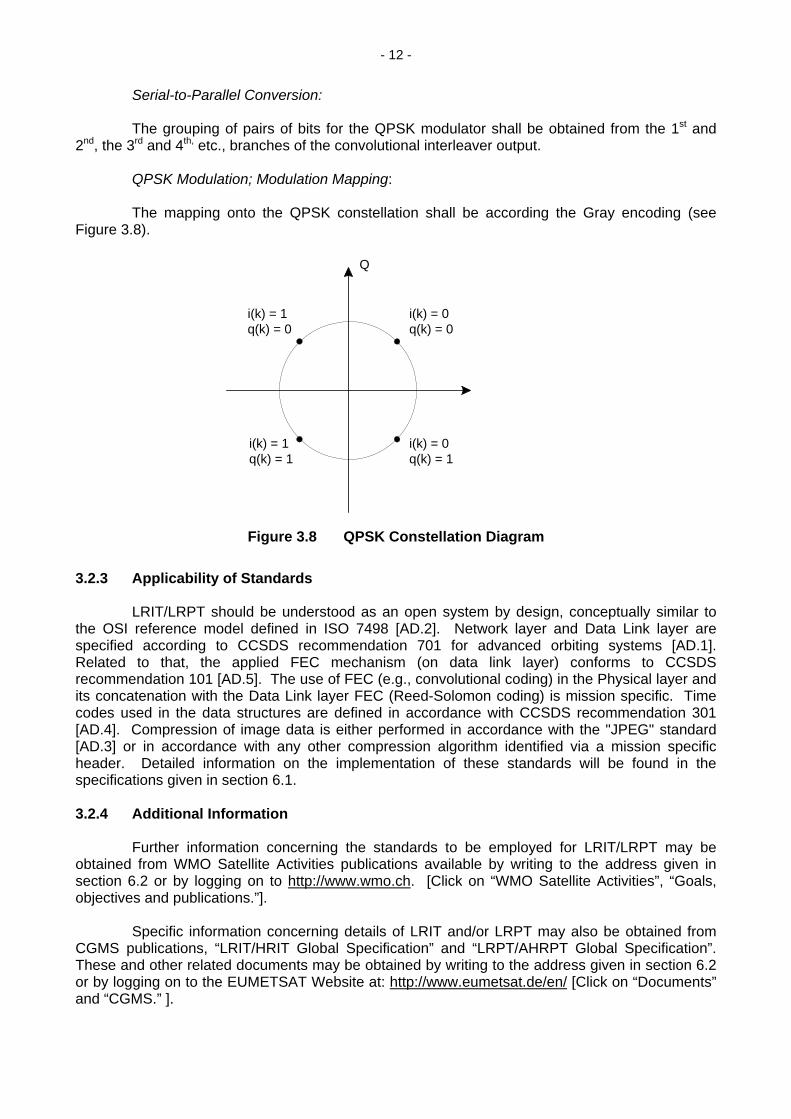
Serial-to-Parallel Conversion: The grouping of pairs of bits for the QPSK modulator shall be obtained from the 1st and 2nd, the 3rd and 4th, etc., branches of the convolutional interleaver output. QPSK Modulation; Modulation Mapping: The mapping onto the QPSK constellation shall be according the Gray encoding (see Figure 3.8).
Q
i(k) = 0q(k) = 0
i(k) = 0q(k) = 1
i(k) = 1q(k) = 1
i(k) = 1q(k) = 0
Figure 3.8 QPSK Constellation Diagram
3.2.3 Applicability of Standards LRIT/LRPT should be understood as an open system by design, conceptually similar to the OSI reference model defined in ISO 7498 [AD.2]. Network layer and Data Link layer are specified according to CCSDS recommendation 701 for advanced orbiting systems [AD.1]. Related to that, the applied FEC mechanism (on data link layer) conforms to CCSDS recommendation 101 [AD.5]. The use of FEC (e.g., convolutional coding) in the Physical layer and its concatenation with the Data Link layer FEC (Reed-Solomon coding) is mission specific. Time codes used in the data structures are defined in accordance with CCSDS recommendation 301 [AD.4]. Compression of image data is either performed in accordance with the "JPEG" standard [AD.3] or in accordance with any other compression algorithm identified via a mission specific header. Detailed information on the implementation of these standards will be found in the specifications given in section 6.1. 3.2.4 Additional Information Further information concerning the standards to be employed for LRIT/LRPT may be obtained from WMO Satellite Activities publications available by writing to the address given in section 6.2 or by logging on to http://www.wmo.ch. [Click on “WMO Satellite Activities”, “Goals, objectives and publications.”]. Specific information concerning details of LRIT and/or LRPT may also be obtained from CGMS publications, “LRIT/HRIT Global Specification” and “LRPT/AHRPT Global Specification”. These and other related documents may be obtained by writing to the address given in section 6.2 or by logging on to the EUMETSAT Website at: http://www.eumetsat.de/en/ [Click on “Documents” and “CGMS.” ].

- 13 -
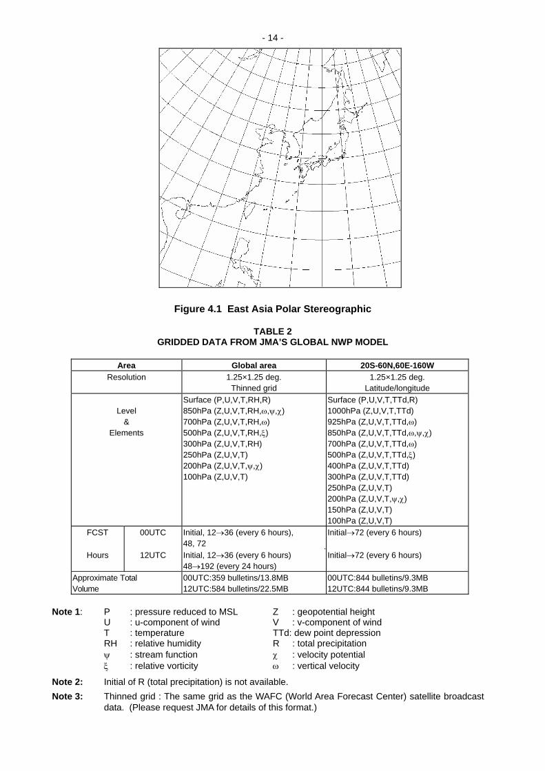
4. OPERATIONAL INFORMATION Because the new systems have not yet been launched, all lists of products to be produced are highly tentative. It is reasonable to project, however, that availability of digital information will lead to the production of numerous products that depend on quantitative data. It is, therefore, appropriate to examine the expected accuracy of data transmitted via LRIT/LRPT. 4.1 Low Rate Information Transmission (LRIT) 4.1.1 Accuracy Because LRIT data and products are prepared through data processing at centres controlled by the operating agencies, the agencies will be responsible for specifying the accuracy of the numerical results disseminated. However, there is no reason that the data cannot be as accurate as the raw data produced by the original sensors. Indeed, depending on the various forms of calibration employed, it is possible for these products could have an absolute accuracy which surpasses that of the original raw data. Hence, users can expect to be able to use these products in numerical forecast algorithms with the same confidence with which they use data which they produce themselves. 4.1.2 Examples of Products Products to be transmitted via LRIT are exemplified by Figure 4.1, (a simulated Polar Stereographic projection of an MTSAT partial image); Table 2, and Table 3, (a preliminary list of products to be disseminated by MTSAT LRIT service from JMA's global model). In addition to traditional satellite imagery products, such as have been transmitted by the WEFAX service in the past, some new types of digital data, not previously available via satellite, will be included in the LRIT. Examples of these data are: conventional meteorological observations such as surface observations (e.g., pressure, temperature, relative humidity, precipitation amount, etc.) and upper air data (e.g., geopotential height, wind speed and direction, temperature, vertical velocity, etc.) The availability of various products in an unencrypted form will be a decision to be taken by each satellite operator. All satellite operators, however, have agreed to provide a basic set of data in a freely distributed, unencrypted format. Furthermore, all satellite operators have agreed that the keys for encrypted data shall be provided to National Meteorological and Hydrological Services (NMHS) without charge. Software is being developed by satellite operators to facilitate manipulating the data to be provided via LRIT. For example, JMA has demonstrated at WMO technical meetings a package which will permit combining of imagery and conventional data to produce displays of wind vectors overlain upon satellite imagery. A further capability is to produce vertical cross-sections of wind, temperature, geopotential height, etc., across a selected horizontal path. This package will be available, at a minimum, to NMHS's which receive MTSAT LRIT data. More information may be obtained from the JMA web site. [Author's note: while all documents are available from the JMA web site, the English version of the JMA web site is under construction. In the interim, some technical documents may be found on the Australian Bureau of Meteorology web site. (See Footnote following section 6.2)]
- 14 -
Figure 4.1 East Asia Polar Stereographic
TABLE 2
GRIDDED DATA FROM JMA’S GLOBAL NWP MODEL
Area Global area 20S-60N,60E-160W Resolution 1.25×1.25 deg. 1.25×1.25 deg.
Thinned grid Latitude/longitude
Level &
Elements
Surface (P,U,V,T,RH,R) 850hPa (Z,U,V,T,RH,ω,ψ,χ) 700hPa (Z,U,V,T,RH,ω) 500hPa (Z,U,V,T,RH,ξ) 300hPa (Z,U,V,T,RH) 250hPa (Z,U,V,T) 200hPa (Z,U,V,T,ψ,χ) 100hPa (Z,U,V,T)
Surface (P,U,V,T,TTd,R) 1000hPa (Z,U,V,T,TTd) 925hPa (Z,U,V,T,TTd,ω) 850hPa (Z,U,V,T,TTd,ω,ψ,χ) 700hPa (Z,U,V,T,TTd,ω) 500hPa (Z,U,V,T,TTd,ξ) 400hPa (Z,U,V,T,TTd) 300hPa (Z,U,V,T,TTd) 250hPa (Z,U,V,T) 200hPa (Z,U,V,T,ψ,χ) 150hPa (Z,U,V,T) 100hPa (Z,U,V,T)
FCST 00UTC Initial, 12→36 (every 6 hours), 48, 72
Initial→72 (every 6 hours)
Hours 12UTC Initial, 12→36 (every 6 hours) 48→192 (every 24 hours)
Initial→72 (every 6 hours)
Approximate Total Volume
00UTC:359 bulletins/13.8MB 12UTC:584 bulletins/22.5MB
00UTC:844 bulletins/9.3MB 12UTC:844 bulletins/9.3MB
Note 1: P : pressure reduced to MSL Z : geopotential height U : u-component of wind V : v-component of wind T : temperature TTd: dew point depression RH : relative humidity R : total precipitation ψ : stream function χ : velocity potential ξ : relative vorticity ω : vertical velocity
Note 2: Initial of R (total precipitation) is not available. Note 3: Thinned grid : The same grid as the WAFC (World Area Forecast Center) satellite broadcast
data. (Please request JMA for details of this format.)
- 15 -
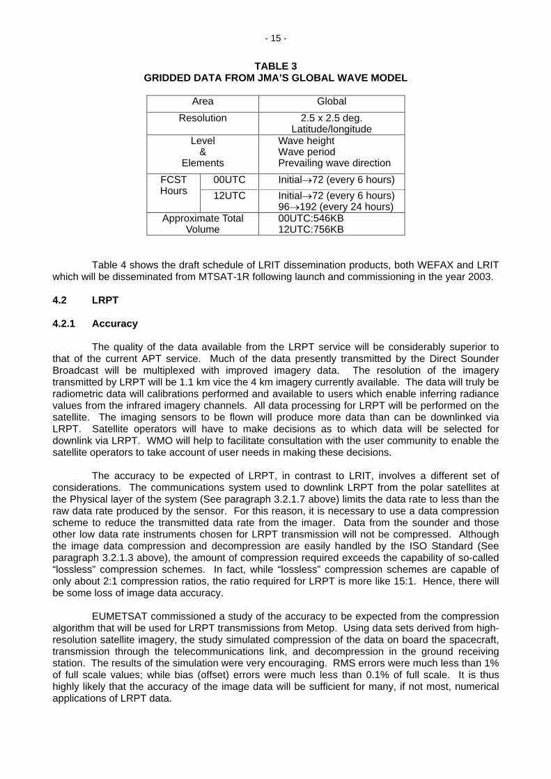
TABLE 3 GRIDDED DATA FROM JMA’S GLOBAL WAVE MODEL
Area Global
Resolution 2.5 x 2.5 deg. Latitude/longitude
Level &
Wave height Wave period Prevailing wave direction Elements
00UTC Initial→72 (every 6 hours) FCST Hours 12UTC Initial→72 (every 6 hours)
96→192 (every 24 hours) Approximate Total
Volume 00UTC:546KB 12UTC:756KB
Table 4 shows the draft schedule of LRIT dissemination products, both WEFAX and LRIT which will be disseminated from MTSAT-1R following launch and commissioning in the year 2003. 4.2 LRPT 4.2.1 Accuracy The quality of the data available from the LRPT service will be considerably superior to that of the current APT service. Much of the data presently transmitted by the Direct Sounder Broadcast will be multiplexed with improved imagery data. The resolution of the imagery transmitted by LRPT will be 1.1 km vice the 4 km imagery currently available. The data will truly be radiometric data will calibrations performed and available to users which enable inferring radiance values from the infrared imagery channels. All data processing for LRPT will be performed on the satellite. The imaging sensors to be flown will produce more data than can be downlinked via LRPT. Satellite operators will have to make decisions as to which data will be selected for downlink via LRPT. WMO will help to facilitate consultation with the user community to enable the satellite operators to take account of user needs in making these decisions. The accuracy to be expected of LRPT, in contrast to LRIT, involves a different set of considerations. The communications system used to downlink LRPT from the polar satellites at the Physical layer of the system (See paragraph 3.2.1.7 above) limits the data rate to less than the raw data rate produced by the sensor. For this reason, it is necessary to use a data compression scheme to reduce the transmitted data rate from the imager. Data from the sounder and those other low data rate instruments chosen for LRPT transmission will not be compressed. Although the image data compression and decompression are easily handled by the ISO Standard (See paragraph 3.2.1.3 above), the amount of compression required exceeds the capability of so-called “lossless” compression schemes. In fact, while “lossless” compression schemes are capable of only about 2:1 compression ratios, the ratio required for LRPT is more like 15:1. Hence, there will be some loss of image data accuracy. EUMETSAT commissioned a study of the accuracy to be expected from the compression algorithm that will be used for LRPT transmissions from Metop. Using data sets derived from high-resolution satellite imagery, the study simulated compression of the data on board the spacecraft, transmission through the telecommunications link, and decompression in the ground receiving station. The results of the simulation were very encouraging. RMS errors were much less than 1% of full scale values; while bias (offset) errors were much less than 0.1% of full scale. It is thus highly likely that the accuracy of the image data will be sufficient for many, if not most, numerical applications of LRPT data.

- 16 -
Table 4 Schedule of LRIT/WEFAX dissemination from MTSAT-1R.
UTC 0 1 0 2 0 3 0 4 0 5 0
00 0 6 3 0IRdisk H I IR-disk(A,B,C,D) WVdisk h, i, w, ii, iii
01 0 6 3 0IRdisk H I WV-disk(K,L,M,N) h,i, ii, iii h, i, w, ii, iii
02 0 6 1 4IRdisk H I trilateration h, i, ii, iii h, i, w, ii, iii
03 0 6 3 0IRdisk H I IR-disk(A,B,C,D) h,i, ii, iii h, i, w, ii, iii
04 0 6 1 4IRdisk H I trilateration h,i, ii, iii h, i, w, ii, iii
05 0 6 1 4IRdisk H I trilateration h, i, ii, iii h, i, w, ii, iii
06 0 6 3 0IRdisk H I IR-disk(A,B,C,D) WVdisk h, i, w, ii, iii
07 0 6 1 4IRdisk H I trilateration h,i, ii, iii h, i, w, ii, iii
08 0 6 1 4IRdisk H I trilateration h,i, ii, iii h, i, w, ii, iii
09 0 6 3 0IRdisk H I IR-disk(A,B,C,D) h,i, ii, iii h, j, w
10 0 6 1 4IRdisk H J h,.., h,..., w
11 0 6 1 4IRdisk H J h,.., h,..., w
12 0 6 3 0IRdisk H J IR-disk(A,B,C,D) WVdisk h,..., w
13 0 6 3 0IRdisk H J WV-disk(K,L,M,N) h,.., h,..., w
14 0 6 1 4IRdisk H J trilateration h,.., h,..., w
15 0 6 3 0IRdisk H J IR-disk(A,B,C,D) h,.., h,..., w
16 0 6 1 4IRdisk H J trilateration h,.., h,..., w
17 0 6 1 4IRdisk H J trilateration h,.., h,..., w
18 0 6 3 0IRdisk H J IR-disk(A,B,C,D) WVdisk h,..., w
19 0 6 1 4IRdisk H J trilateration h,.., h,..., w
20 0 6 1 4IRdisk H J trilateration h,.., h, j, w, ii, iii
21 0 6 3 0IRdisk H I IR-disk(A,B,C,D) h,i, ii, iii h,..., w, ii, iii
22 0 6 1 4IRdisk H I trilateration h,i, ii, iii h, i, w, ii, iii
23 0 6 1 4IRdisk H I trilateration h,i, ii, iii h, i, w, ii, iii
IR-PS VS-PS WV-PS IR-DISK WV-DIS
6 0
KWEFAX H I A,B,C,D(divided) K,L,M,N(divided)
J(enhanced)LRIT regular h(IR1) i w IRdisk WVdiskLRIT special j (IR4) ii,iii(detailed)

- 17 -
4.2.2 Available Data For the first EUMETSAT Polar Satellite, METOP-1, two data streams will be available. The NOAA furnished instruments (AVHRR, AMSU-A1, AMSU-A2, HIRS, SEM, DCS) will generate raw data which will be time tagged and formatted by the spacecraft NOAA Interface Unit (NIU). This NIU will also provide data compression of the AVHRR data for transmission on the LRPT link. The IASI, MHS, GRAS, GOME and ASCAT instruments provide data in the form of CCSDS source packets. The satellite provides housekeeping data, GRAS positioning and timing data and administrative messages in the form of CCSDS source packets. The application data provided by the Low Resolution Picture Transmission (LRPT) link are as follows:
- Compressed resolution imagery on selected channels of the AVHRR; - Infrared and microwave sounding data from the Meteorological Payload: AMSU-A1,
AMSU-A2, MHS, and HIRS; - SEM data; - Spacecraft Housekeeping data; - GRAS positioning and timing data; - Administrative messages.
4.3 High Rate Information Transmission (HRIT)
[This paragraph number reserved for a future edition of this document.] 4.4 Advanced High Rate Picture Transmission (AHRPT)
[This paragraph number reserved for a future edition of this document.] 4.5 Other Services 4.5.1 Internet
[This paragraph number reserved for a future edition of this document.] 5. AVAILABILITY OF COMMERCIAL RECEIVING STATIONS FOR LRIT/LRPT Although manufacture of receiving stations for receiving LRIT/LRPT is not yet widespread, all satellite operators are working with industry to define and make available the necessary information to facilitate design and fabrication of Low Rate User Stations (LRUS). EUMETSAT has released both global and mission specific specifications to industry in 1999 and JMA has similarly published LRIT receiving station specifications. Each operator is procuring a limited, but significant number of LRIT receiving stations for use by their respective user community (i.e., regional and national meteorological offices); a provision of the initial contract is that design details be made available to other manufacturers. Hence the initial non-recurring costs should be largely borne by the satellite operating agencies. Delivery of these first receiving stations is expected early in the year 2000. CGMS has likewise authorized WMO to post both Global and Mission Specific user station specifications on the WMO Satellite Activities web pages. The list of direct broadcast receiving station manufacturers contained on the WMO web site will be annotated to show those manufacturers accredited to produce LRIT and LRPT receiving stations, as they become available. The first few firms, accredited by JMA for LRUS for MTSAT are already available. This site will be regularly updated so that Members can avail themselves of the latest information concerning sources of qualified receiving equipment.

- 18 -
6. REFERENCES 6.1 Documents WMO Application and Presentation Specifications for the LRIT/LRPT/HRIT/HRPT Data Format
(WMO/TD No. 910, (SAT-19)) EUMETSAT/CGMS LRIT/HRIT Global Specification, Document CGMS-03 LRPT/AHRPT Global Specification, Document CGMS-04 MSG Ground Segment - LRIT/HRIT Mission Specific Implementation,
Doc. No. MSG/SPE/057 JAPAN MTSAT LRIT Mission Specific Implementation CCSDS [RD.1] CCSDS: “Advanced Orbiting Systems, Networks and Data Links: Architectural
Specification”, CCSDS recommendation 701.0-B-2, November 1992 [RD.2] CCSDS: “Telemetry Channel Coding”, CCSDS recommendation 101.0-B-3,
May 1992 [RD.3] CCSDS: “Time Code Formats”, CCSDS recommendation 301.0-B-2, April
1990 [RD-10] CCSDS Document No. 101.0-B-3; Blue Book; Telemetry Channel Encoding 6.2 Postal Addresses and Websites WMO:
World Meteorological Organization Website: http://www.wmo.ch WMO Satellite Activities Office 7 bis, avenue de la Paix Case Postale 2300 CH-1200 Geneva 2 Switzerland.
China:
China Meteorological Administration Website: http://www.cma.gov.cn 46 Baishiqiao Road BEIJING 100081 People's Republic of China
EUMETSAT/CGMS:
Secretariat, CGMS EUMETSAT Website: http://www.eumetsat.de Am Kavalleriesand 31 P.O. Box 100555 D-64295 DARMSTADT Germany

- 19 -
India: India Meteorological Department Mausam Bhavan Lodi Road NEW DELHI 110 003 India Japan: 1 Japan Meteorological Agency Website: http://www.kishou.go.jp/ Office of Meteorological Satellite Planning [Japanese language] 1-3-4 Otemachi and Chiyoda-ku http://www.kishou.go.jp/english TOKYO 100-8122 [English language] Japan Russian Federation: Website: http://sputnik.infospace.ru Scientific and Research Centre on Space Hydrometeorology PLANETA 7, Bolshoy Predtechensky per. 123242 MOSCOW Russian Federation
USA: Website: http://www.nesdis.noaa.gov NOAA/NESDIS [Click on “Office of Systems Development”] Office of Systems Development Suitland Federal Center FB-4, Room 3300 Suitland, MD 20746 USA
CCSDS Website:
http://www.ccsds.org/publications.html#telemetry
6.3 Other Useful Websites
(1) International TOVS Working Group (ITWG):
- http://www.bom.gov.au/bmrc/ITWG.htm (2) Co-operative Institute for Meteorological Satellite Studies (CIMSS), University of
Wisconsin:
- http://cimss.ssec.wisc.edu/ (3) European Centre for Medium-Range Weather Forecasts (ECMWF)
- http://www.ecmwf.int/
(4) Co-operative Institute for Research in the Atmosphere (CIRA), Colorado State University:
- http://www.cira.colostate.edu
1 /Author's note: The JMA English language home page is under construction. Interim access for some technical documents may be found on the Australian Bureau of Meteorology web site, http://ho.bom.gov.au/sat/MTSAT/MTSAT.shtml.
- 20 -
ACRONYMS AND ABBREVIATIONS AHRPT Advanced High Rate Picture Transmission AOS Advanced Orbiting Systems or Acquisition of Signal [of a spacecraft] APID Application Process Identifier APT Automatic Picture Transmission ASCAT Advanced Scatterometer CADU Channel Access Data Unit CAL Computer Aided Learning CCSDS Consultative Committee for Space Data Systems CGMS Coordination Group for Meteorological Satellites CP_PDU CCSDS Path Protocol Data Unit CRC Cyclic Redundancy Code CVCDU Coded Virtual Channel Data Unit DCS Data Collection System DSB Direct Sounding Broadcast Electro Geostationary meteorological satellite (Russian Federation) ESSA Environmental Sciences Services Administration EUMETSAT European Organisation for the Exploitation of Meteorological Satellites FEC Forward Error Correction FY-1 Feng Yen-1: Polar weather satellite (China) FY-2 Feng Yen-2: Geostationary weather satellite (China) GHz Gigahertz [as 109 Hertz] GMS Geostationary Meteorological Satellite (Japan) GOES Geostationary Orbiting Environmental Satellite (USA) GOME Global Ozone Monitoring Experiment (an instrument on ERS-2 and METOP) GRAS GNSS Receiver for Atmospheric Sounding HIRS High-resolution InfraRed Radiation Sounder HRIT High Rate Information Transmission IASI InfraRed Atmospheric Sounding Interferometer IN_SDU Insert Service Data Unit INSAT INdian geostationary meteorological SATellite ISO International Organization for Standardization ITOS Improved TIROS Operational System ITU-R Radio Sector of the International Telecommunication Union JMA Japan Meteorological Agency kHz Kilohertz LRIT Low Rate Information Transmission LRPT Low Rate Picture Transmission LST Local Standard Time LRUS Low Rate User Station M_PDU Multiplex Protocol Data Unit Meteor Polar weather satellite (Russian Federation) Metop EUMETSAT polar weather satellite MHS Microwave Humidity Sounder MHz Megahertz [as 106 Hertz] MTSAT Multifunction Transport SATellite (Japan; successor to GMS) NIU NOAA Interface Unit NMHS National Meteorological and Hydrological Service NOAA National Oceanic and Atmospheric Administration NPOESS National Polar-orbiting Environmental Satellite System (USA) OSI Open Systems Interconnection PCA_PDU Physical Channel Access Protocol Data Unit PEC Post Error Correction PN Pseudo Noise QPSK Quadrature Phase Shift Keying RF Radio Frequency
- 21 -
RHCP Right Hand Circular Polarised RX Receive Function SEM Space Environmental Monitor S/C Spacecraft SCID Spacecraft Identifier SDU Service Data Unit SR Scanning Radiometer TBC To be confirmed TBD To be determined TX Transmit function UTC Universal Time Co-ordinated UW Unique Word VC Virtual Channel VCA Virtual Channel Access VCA_SDU Virtual Channel Access Service Data Unit VCDU Virtual Channel Data Unit VCDU-ID Virtual Channel Data Unit Identifier VCLC Virtual Channel Link Control VHRR Very High Resolution Radiometer VTPR Vertical Temperature Profile Radiometer WEFAX Weather Facsimile WMO World Meteorological Organization