mielec landfill site pre-feasibility study · the landfill is located at the premises of the...
TRANSCRIPT
MIELEC LANDFILL SITE PRE-FEASIBILITY STUDY
Prepared for:
U. S. Environmental Protection Agency Landfill Methane Outreach Program
Completed by:
Oil and Gas Institute - Poland
November 2009

M i e l e c L a n d f i l l S i t e P r e - f e a s i b i l i t y S t u d y
2
This publication was developed under Assistance Agreement no. XA-83397301-0 awarded by the U.S. Environmental Protection Agency. It has not been formally reviewed by EPA. The views expressed in this document are solely those of Instytut Nafty i Gazu and EPA does not endorse any products or commercial services mentioned in this publication.

M i e l e c L a n d f i l l S i t e P r e - f e a s i b i l i t y S t u d y
3
List of contents
Summary ............................................................................................................................................................. 4
1. Project limitations ..................................................................................................................................... 4
2. Introduction............................................................................................................................................... 5
2.1 Goal.................................................................................................................................................5
2.2 Resources.......................................................................................................................................6
2.3 Landfill location...............................................................................................................................6
3. Characteristics of the Mielec landfill ........................................................................................................ 7
3.1 Characteristic of the site and its vicinity ........................................................................................7
3.2 Technology of solid waste deposition............................................................................................9 3.2.1 Construction of the landfill........................................................................................9 3.2.2 Waste deposition/landfill operation ....................................................................... 12
3.3 Technical evaluation of the landfill ............................................................................................. 13
3.4 Environmental impact of the present landfill operation.............................................................. 14
4. Measurements of a landfill gas composition .........................................................................................15
5. Expected gas production at the landfill .................................................................................................19
5.1 Data on the mass of solid wastes deposited in the landfill (historical data and forecast)........ 22
5.2 Gas production modeling ............................................................................................................ 22
6. Systems of landfill gas extraction ..........................................................................................................27
6.1 Description of the gas extraction technology ............................................................................. 27 6.1.1 Elements of installation for gas extraction............................................................ 27 6.1.2 Connection of elements of a landfill gas extraction installation........................... 29
6.2. Proposal of gas extraction at the Mielec municipal solid waste landfill ........................................ 30 6.2.1 Drilling................................................................................................................................. 30 6.2.2 Construction of the gas extraction well ............................................................................. 30 6.2.3 Gas transport to the collection station............................................................................... 31 6.2.4 Gas Collection Station ....................................................................................................... 31
7. Utilization and reuse of landfill gas........................................................................................................32
7.1 Landfill gas utilization .................................................................................................................. 32
7.2 Proposal of gas utilization at the Mielec landfill ......................................................................... 34
8. Simplified economic analysis of the proposed option of landfill gas intake and utilization .................34
8.1 Investment costs and the proposed project schedule ............................................................... 34
8.2 Project operational costs............................................................................................................. 35
8.3 Revenues during the project implementation ............................................................................ 36 8.3.1 Quantity of energy generated from the gas.......................................................... 36 8.3.2 Revenues from the sold electricity........................................................................ 38 8.3.3 Revenues from the „green certificates” ................................................................ 39
8.4 Calculation of NPV i IRR. ............................................................................................................... 39
9. Summary ................................................................................................................................................43
10. Literature.................................................................................................................................................45

M i e l e c L a n d f i l l S i t e P r e - f e a s i b i l i t y S t u d y
4
Summary
The report has been developed to estimate the possible recovery and reuse of landfill gas produced at
the municipal solid waste landfill at Mielec, located at the Southern East of Poland. All facilities located
in the premises of the landfill are managed by the Zakład Utylizacji Odpadów Komunalnych Sp. z o.o. at
Mielec, owned by the Gmina Miejska Mielec. The municipal solid waste landfill at Mielec has been
continuously collecting solid wastes since 1997. The landfill is to be closed and recultivated in 2010.
The landfill accepts mixed solid wastes; quantity of which is registered with an electronic scale.
The surface area of the landfill, measured at the ground elevation, is about 1,5 ha. The overall height of
a waste layer is about 18 m; the depth of the wastes deposited under ground is 4 m. The overall bulk
mass of the wastes deposited at the landfill is about 235 000 Mg.
Calculations of the gas production have been performed using two mathematical models. They are the
US EPA Landgem model and the IGNIG model, developed in the Oil and Gas Institute. The data on the
waste load was provided by the landfill Manager. Based on the expected gas volume, a simplified
economic analysis has been performed, assuming electricity production. The analysis showed the
economical feasibility of the project based on the idea of electricity generation from the LFG at the
Mielec municipal landfill.
1. Project limitations
A forecast of the gas production, necessary for the development of the Pre-feasibility study, called
„Report”, was performed based on the data delivered by the owner (manager) of the landfill and
supplemented by the field measurements conducted during the site visits. The visits have been
described in details in chapter 5 of the Report.
The main source of information about the landfill was the document (provided by the owner) entitled
„Dokumentacja do wniosku o zmianę pozwolenia dla instalacji do składowania odpadów,
z wyłączeniem odpadów obojętnych, o zdolności przyjmowania ponad 10 ton odpadów na dobę
zakładu Utylizacji Odpadów Komunalnych Sp. z o.o. w Mielcu przy ulicy Wolności 171”.
Estimations concerning gas stream volume produced at the landfill as well as all economic analysis
were performed based on the best knowledge and professional experience of the authors.

M i e l e c L a n d f i l l S i t e P r e - f e a s i b i l i t y S t u d y
5
Although the Oil and Gas Institute (INiG) did its best while preparing the report, calculations of gas
production may still not be very accurate and therefore a preliminary economic analysis based on this
information alone may have some errors. The errors are mostly due to scarce information on
morphology of solid wastes deposited in subsequent years of landfill operation.
2. Introduction
This Pre-feasibility study has been developed by the INiG as a part of the Project „Landfill gas in
Poland: capabilities and awareness of its potential for energy generation” conducted with the support of
the U.S. EPA Landfill Methane Outreach Program (LMOP), a apart of the international initiative
Methane to Markets Partnership (M2M)1.
2.1 Goal
The main goal of the report was to asses the volume of the gas generated at the municipal waste
landfill at Mielec and to develop technical possibilities of its recovery in order to:
• Avoid emission of green house gas into atmosphere,
• Use its energetic properties to change chemical energy into heat or electricity.
The goal has been achieved due to:
� Analysis of technical parameters of the landfill, mass of deposited solid wastes and landfill
managing procedure.
� Analysis of gas characteristics.
� Forecast of gas productivity from the landfill.
� Possibility of intake and usage of the produced gas; assumption of technical parameters of gas
recovery and reuse.
� Presentation of a proposed technology of gas recovery and reuse.
� Simplified economic analysis of the selected option (process).
1 www.methanetomarkets.org

M i e l e c L a n d f i l l S i t e P r e - f e a s i b i l i t y S t u d y
6
2.2 Resources
The following resources have been used in the report:
� „Dokumentacja do wniosku o zmianę pozwolenia dla instalacji do składowania odpadów,
z wyłączeniem odpadów obojętnych, o zdolności przyjmowania ponad 10 ton odpadów na
dobę zakładu Utylizacji Odpadów Komunalnych Sp. z o.o. w Mielcu przy ulicy Wolności 171”.
� Result of the field measurements collected at the site on:
- 28 March, 2007
- 28 May 2007
- 25 June 2007
- 12 October 2009
Additional sources of information were e-mail messages exchanged on the daily basis between INiG
and the landfill manager, during the preparation of the report.
2.3 Landfill location
The landfill is located at Mielec, district Mielec, Podkarpackie Voivodeship (Figure 1).
Figure 1. Location of the municipal solid waste landfill at Mielec[1].

M i e l e c L a n d f i l l S i t e P r e - f e a s i b i l i t y S t u d y
7
The landfill described in the report is located at Mielec, Wolności Str. No. 171. According to the Lot
Register the landfill covers the lots registered under the following numbers: 1431/9 (a part of the lot),
1435/1, 1435/3, 1431/5 and 1431/6. The solid waste landfill is located east from the city of Mielec
center, about 200 meters from the Mielec – Kolbuszowa road. It is placed in a large forest complex,
which belongs to the Mielec forestry. The border of the Tuszym Forestry Authority follows the border of
the Mielecko-Kolbuszowskiego Area of the Protected Landscape (about 50 m east from the landfill cell
border) [1].
3. Characteristics of the Mielec landfill
The landfill is located at the premises of the Zakład Utylizacji Odpadów Komunalnych
Sp. z o.o. w Mielcu, Wolności Str. No 171, Podkarpackie Voivodeship. Zakład Utylizacji Odpadów
Komunalnych is the operator of the landfill.
The landfill started its operation in 1997 (based on the operation permit issued by the Regional Office)
and since September 1997 it continues its operation under management of the Zakład Utylizacji
Odpadów Komunalnych Sp. z o.o. [1].
3.1 Characteristic of the site and its vicinity
In the closest neighborhood of the landfill are:
� to the north – forest areas, further on a municipal cemetery and housing development
(about 600 m from the landfill),
� to the south - forest areas and then the Wolności Str,
� to the east – a local road , and then forests,
� to the west - forest areas, and then towards south –east housing developments (about 500 m
from the landfill) [1].
The landfill is located in the large forest complex, part of the Tuszym Forestry Authority and Mielec
region. The border of the Tuszym Forestry Authority is also the border of the Mielecko-Kolbuszowski
Area of the Protected Landscape (about 50 m east from the landfill cell border). Eastern part of the City
of Mielec belongs to the Mielecko-Kolbuszowsko-Głogowski Area of the Protected Landscape. These
areas are mostly covered by forests, but also there are some farming lands, poor-quality meadows and
ramshackle buildings. The area covers about 50 099 ha. At the premises of the Mielecko-Kolbuszowski

M i e l e c L a n d f i l l S i t e P r e - f e a s i b i l i t y S t u d y
8
Area of the Protected Landscape the „Zabłocie” Nature Park has been established, to protect a natural
collection of flora of the old Sandomierski Forest, with its numerous species of rare and endangered
plants as well as nesting and breeding sites of rare bird species.
There is no plan to erect any farm-house developments in the closest vicinity of the landfill, neither the
public buildings, hospitals or other areas, where a permanent or occasional presence children and
youngsters would be expected (schools, nursery, kinder gardens) are planned in this area. The closest
residential buildings are located rather far from the landfill, i.e.:
� to the south-west - about 500 m from the landfill’
� to the north-west - about 600 m from the landfill.
About 2500 m north form the landfill, are local water reservoirs called ” Cyranowskie Ponds” together
with a dewatering system. There are no legally protected trees in the neighborhood (nature
monuments) – the closest trees can be found in the Wojslaw’s Mention Park, about 3000 m south -
west.
The facility is not adjacent to any national parks, nature preserve, landscape parks, etc.
Both, the landfill and the Mielec area are located within the border of the main Ground Water Reservoir
no 425 (GZWP no 425 Dębica – Stalowa Wola – Rzeszów) and close to the Szydłowiec water intake
impact area. The water intake accumulates about 16,3 thousand m3 and its daily output goes up to
3,75 thousand m3/d. The landfill is located in the area without natural groundwater insulation. Directly
under the surface, the entire aeration zone is made of fine and semi-fine sands. Therefore, a direct
infiltration of rainwater is responsible for a recharge of water resources in this area [1].
In a close vicinity of the landfill there are no places designated as the NATURA 2000 Areas; these
areas are located couple hundred meters away, so they are beyond the impact of the landfill.
The area is located in the catchment of the Bobolanka River; a water elevation at the Mielec location is
162 MSL. About 1,5 km west from the landfill a partially covered trench system is located.
The facilities of the Składowiska Zakładu Utylizacji Odpadów Komunalnych Sp. z o.o. w Mielcu are
actual buildings which location is approved by the local General Plan of Spatial management of the City
of Mielec [1].
M i e l e c L a n d f i l l S i t e P r e - f e a s i b i l i t y S t u d y
9
Location of the landfill is rather convenient with respect to the surrounding areas (forest – a protective
green belt) and its distance to the existing or planned residential buildings. The drawbacks of the
location are connected with its location at the GZWP 425 lot and lack of a natural geological barrier e.g.
a clay layer to protect groundwater.
3.2 Technology of solid waste deposition
3.2.1 Construction of the landfill
The Mielec landfill is a trench/area landfill.
Sidewalls and the base of the landfill are water tight and lined with a double layer of synthetic
membrane (geomembrane HDPE; high density polyethylene); thickness of the upper membrane is
1,5 mm while the lower one is 1,0 mm. A monitoring collection system is placed between the
geomembranes. It is made of PCV pipes; thickens of the drainage layer is 30 cm. Between
geomebranes also a DDS tightened layer system is placed; its sensors are situated at three different
points of the landfill, at the east side. Permeability tests controlling the upper geomembrane (1,5 mm
thick) are performed occasionally with a DDS system. The first layer of solid wastes (minimum
thickness of 2 m) was placed without prior thickening, and this way a protective layer for the
geomembranes and a drainage system was assured. Upon the 2 m thick solid wastes layer the first
sanitary sand layer of 30 cm thickness was placed [1].
Rainwater (leachate) seeping through solid wastes is collected from the landfill body with a drainage
system (d=100 mm) placed in a gravel cover, which ends up in a collector d=200 mm discharging to the
collection well. In the well a submersible pump with a float is mounted. The leachate collection pump
allows to pump out the leachate on a regular basis to the main reservoir of total volume of 480 m3 and
working volume of 224,7 m3. Before entering the main reservoir the leachate passes through a three-
stage retention tank, for a pre-treatment:
� first stage of working volume of 80 m3 – leachate aeration with a jet pump to equalize and
freshen the flow;
� second stage of working volume of 92,7 m3 – leachate aeration; reduction of organic pollutants;
� third stage of working volume of 52 m3 – serves as a intake chamber for a sanitation truck.

M i e l e c L a n d f i l l S i t e P r e - f e a s i b i l i t y S t u d y
1 0
Leachates from the main reservoir is transported by the sanitation truck to the EURO-EKO Sp. z o.o.
wastewater treatment plant [1].
Sidewalls of the landfill at the beginning of its operation were enforced with a grid (made from tires) and
covered with sand; sidewalls slope 1:3. Around the pit there is an embankment; its heights is 2 MSL
and slope 1:3. Outside of the embankment a leachate trench is constructed. It discharges to the forest
trench, passing near by the northern side of the landfill.
The landfill has a basic installation to utilize gas produced during the waste stabilization.
The installation consists of:
� one collection well made of concrete rings of diameter of 1000 mm, based at the landfill base.
The well is constructed from rings of 1 m diameter sealed with bituminous binders. In the
course of landfill operation the well has been elevated to match the top of the landfill. At the top
of the well a manual gas flare is installed (Photo 1).
� collection system layed horizontaly, at the level of a collection well base (elevetion 2 m below
the ground surface). The 150 mm PEPP pipes are used as a collection system; they are
covered with a gravel layer (particle diameter 41/63 mm; 40 cm thick). The drainage pipes are
arranged in such a way that they come out around from the collection well sump. The pipes
end 6 m from the outer border of the landfill sidewall. The total length of all horizontal drainage
pipe segments is 380 m [1].
Photo 1. Gas collection well with a gas flare.
Technical parameters of the landfill:
� surface area of a landfill base – 1,5 ha (ground level), 1,2 ha (base bottom),

M i e l e c L a n d f i l l S i t e P r e - f e a s i b i l i t y S t u d y
1 1
� total height of the deposited wastes is about 18 m (including a 4 m thick layer located under the
surface),
� the total landfill volume – 160 580 m3,
� maximum bulk mass of deposited wastes – 234 856 Mg [1].
Technical infrastructure of the landfill comprises:
� Landfill area at top level 1,5 ha and 4 m below the ground level.
� Office and staff building with a scale, cloakroom, toilets and a janitor room.
� Sanitary sewage reservoir.
� Shelter for a compactor and delivery truck.
� Fuel storage for compactor and additional vehicles (excavator, truck).
� Scale made by Schenek.
� Umbrella roof for recyclables and their manual sorting (here a mechanical/manual sorting plant
is to be built).
� Pump station for pumping leachate from a main drainage system.
� No-discharge control well for a between – liner drainage.
� No-discharge water-tight reservoir for leachate; its volume 480 m3. The reservoir is equipped
with two jet-pumps MS1-24 Z.
Figure. 2 Layout of the solid waste landfill.

M i e l e c L a n d f i l l S i t e P r e - f e a s i b i l i t y S t u d y
1 2
3.2.2 Waste deposition/landfill operation
Solid waste deposition proceeds in the following way:
� delivery of truck loads of solid waste to a specific location at the top of the landfill (designated
daily cells),
� discharge of the loads and exit from the landfill,
� spreading out of solid waste in a form of even layers,
� compaction of waste (comprimation, thickening) with a compactor,
� formation of intermediate layers between waste layers and landfill sidewalls,
� upper layer of solid waste is leveled to a pre-set slope,
� 2 meters high waste layer is covered with an inert material (sand bed of 15 cm thickness),
The Mielec solid waste landfill is operated with a horizontal method, which enables good wastes
compaction and maximum utilization of landfill capacity. Solid wastes are delivered to the landfill by self
discharge garbage trucks that enter the property from its west side. Bulk mass of solid waste is
monitored at the landfill entrance, where an electronic truck scale weights the incoming waste loads.
Trucks leaving the landfill have their tires washed and disinfected in a special disinfection pit.
On average, once a day 9 garbage trucks (with a high compaction factor) deliver about 88 Mg of waste
to the landfill;3 out of 9 trucks deliver solid waste in KP-7 containers. Approximately, 60 runs of delivery
trucks are registered daily at the landfill and maximum 8 trucks per hour can be unloaded at the site.
Once wastes have been mechanically dumped from the trucks or containers to a landfill surface, it is
spreaded and compacted on the pre-designated cell with the Hanomag CL 240 compactor (Photo 2).
Compaction of the waste layer reduces its thickness from 50 cm to 17 cm, and this way a larger landfill
capacity is available for waste deposition. Insulation intermediate layers are placed between 2,0 m thick
compacted layers of waste. Materials used for intermediate layers include mineral materials such as:
sand, ash, slag, construction waste or street sweepings. Thickness of the intermediate layer is about
15 cm.
The maximum bulk mass of solid waste delivered to the Mielec landfill is 176 Mg/day and
22 000 Mg/year (at 250 working days/year) [1].
The total mass of solid wastes deposited at the landfill is presented in Table 6 (chapter 5).
M i e l e c L a n d f i l l S i t e P r e - f e a s i b i l i t y S t u d y
1 3
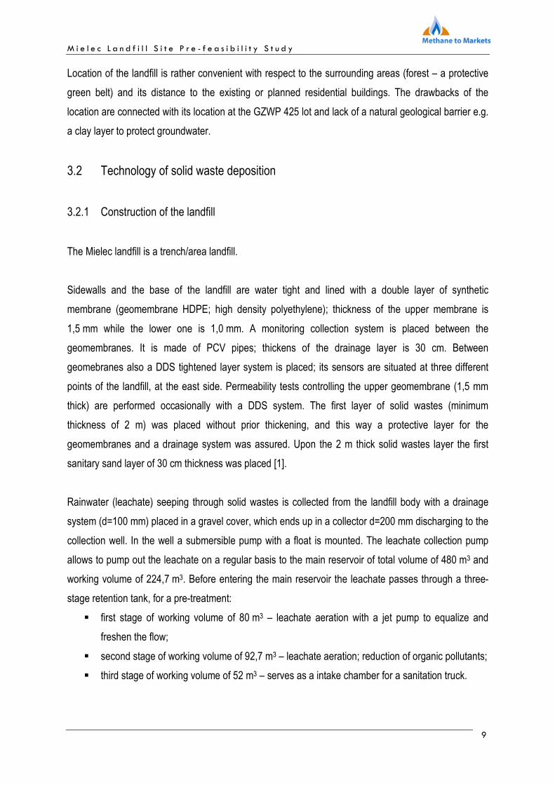
Photo 2. Compactor. Photo 3. Sorting plant.
A manual sorting plant is located at the Mielec landfill. At the sorting plant, additional recovery of
recyclables is performed after their selective collection throughout the city (Photo 3). The sorting facility
has two bailing units for paper and plastics; their capacity is 400 kg of paper/h (for newspapers up to
600 kg/h) and 300 kg of plastics/h. In the sorting plant, the wastes collected selectively throughout the
city are additionally sorted and stored separately in special compartments, or, as in case of waste
papers and plastics, after their compaction in a separate section of the technological building [1].
3.3 Technical evaluation of the landfill
The landfill infrastructure, both located on the surface (access roads and squares) and underground
(water and sewage systems, electric conduits), is in good technical conditions due to a rather short
landfill operation period.
So far the landfill has been properly operated.
A gas venting system is designed as a single vertical well together with a horizontal collection system
connected to its base. As such, it does not assure sufficient gas extraction from the landfill. It would be
recommended to build additional vertical venting wells, as it was described in details in chapter 6 of this
report.

M i e l e c L a n d f i l l S i t e P r e - f e a s i b i l i t y S t u d y
1 4
3.4 Environmental impact of the present landfill operation
Actual technology used at the landfill results in the following hazards to the environment:
atmospheric air:
� emission of landfill gas,
� uncontrolled emission of ammonia from a leachate reservoir,
� uncontrolled emission of fumes due to a road traffic (delivery trucks, excavator/loader,
compactor at the landfill base and a fork lift next to shelter).
noise emission:
� noise generated by a stationary equipment located within and outside of the sorting plant
(technological equipment),
� noise generated by external air conditioning units,
� road traffic noise (delivery trucks, excavator/loader, compactor and a fork lift).
soil and groundwater:
� deposition of solid wastes at a landfill base (leachate generation),
� leachate collection system, sanitary and storm water sewer system, drainage system of water
from the area between liners.
water and sewage management :
� leachate generation (discharge to the wastewater treatment plant),
� runoff from internal roads,
� storm water, sanitary sewage, water from the area between liners,
waste management:
� generation of hazardous wastes and other then hazardous wastes due to technological
operations,
� wastes recovery (sorting – actually in a manual mode, ultimately in a manual/mechanical
mode),
� production of mixed municipal wastes (in office and staff buildings).

M i e l e c L a n d f i l l S i t e P r e - f e a s i b i l i t y S t u d y
1 5
other elements of the environment; due to its location (surrounded by forests; no residential buildings or
historic monuments in the close vicinity; lack of electromagnetic radiation; no trees removed) - landfill
does not have a major impact on the environment [1].
Emission of air pollutants takes place mostly around the internal access roads (fuel gas emission) as
well as the landfill base and the area where the leachate reservoir is located. The landfill is a source of
an uncontrolled emission of landfill gas throughout a landfill cover. A point source emission takes place
at a gas flare, when a landfill gas is burned [1].
In case of uncontrolled emission, it can be limited by reduction of road traffic at the site. This can be
achieved by developing a proper logistics of waste delivery and following operational schedule of
a compactor and a excavator/loader. Emission of a landfill gas through a landfill surface area may be
reduced by suitable waste deposition (daily intermediate insulation covers) and a properly design and
constructed gas venting system, equipped with gas utilization units. Utilization of gas for electricity
and/or heat generation may additionally reduce emission of landfill gas from the flare [1].
4. Measurements of a landfill gas composition
Monitoring of concentration of major components of landfill gas was performed at the Mielec landfill on
October 12, 2009. Additionally, in 2007, the staff from the Oil and Gas Institute carried out three more
series of similar analytical measurements.
Gas probes and vent wells were used to extract gas samples for analysis.
Gas probes enable to take gas samples from the underground layers of the landfill. Probes are made of
a 3/4 in. galvanized pipe. To easily penetrate landfill layers, the pipe has a steal point chisel mounted at
its top; it is loosely mounted and remains inside the waste layer after the measurement has been
completed. The gas probe is driven into the landfill with a 20 kg hammer; and the ring which transfers
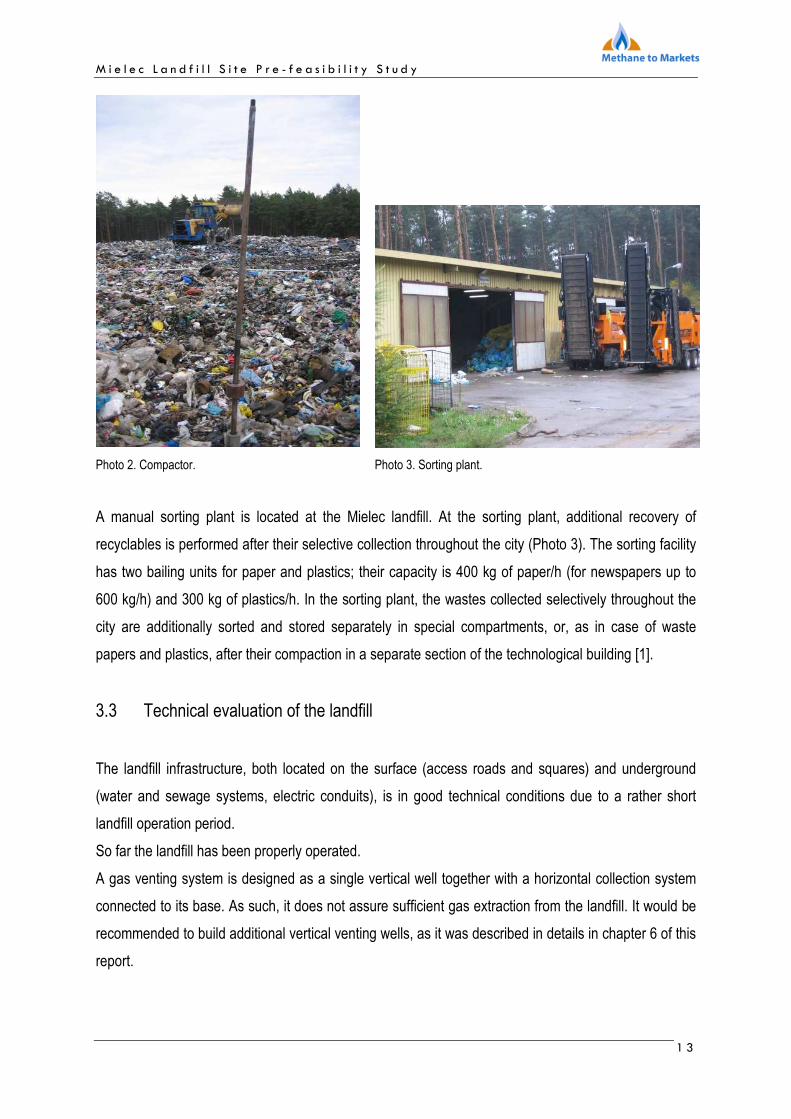
the hammer’s energy. Technique of a gas probe inserting into the bulk waste is shown in Figure 3.
M i e l e c L a n d f i l l S i t e P r e - f e a s i b i l i t y S t u d y
1 6
Figure. 3. Sampling of a landfill gas with a driven gas probe.
Analysis of landfill gas main components: methane, carbon dioxide, oxygen, hydrogen sulphide and
carbon oxide was performed using the gas analyzer GA - 2000 manufactured by Geotechnical
Instruments.
Physical-chemical parameters of gas extracted during measurements carried out in years 2007 and
2009 were summarized in Tables 1, 2, 3 and 4.
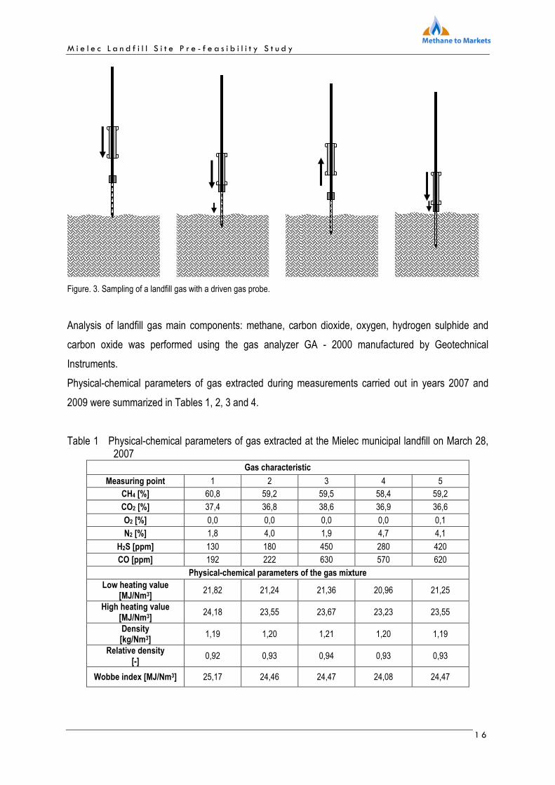
Table 1 Physical-chemical parameters of gas extracted at the Mielec municipal landfill on March 28, 2007
Gas characteristic
Measuring point 1 2 3 4 5 CH4 [%] 60,8 59,2 59,5 58,4 59,2
CO2 [%] 37,4 36,8 38,6 36,9 36,6
O2 [%] 0,0 0,0 0,0 0,0 0,1
N2 [%] 1,8 4,0 1,9 4,7 4,1
H2S [ppm] 130 180 450 280 420
CO [ppm] 192 222 630 570 620
Physical-chemical parameters of the gas mixture
Low heating value [MJ/Nm3]
21,82 21,24 21,36 20,96 21,25
High heating value [MJ/Nm3]
24,18 23,55 23,67 23,23 23,55
Density [kg/Nm3]
1,19 1,20 1,21 1,20 1,19
Relative density [-]
0,92 0,93 0,94 0,93 0,93
Wobbe index [MJ/Nm3] 25,17 24,46 24,47 24,08 24,47

M i e l e c L a n d f i l l S i t e P r e - f e a s i b i l i t y S t u d y
1 7
Table 2 Physical-chemical parameters of gas extracted at the Mielec municipal landfill on May 28, 2007.
Gas characteristic
Measuring point 1 2 3 4
CH4 [%] 62,7 63,1 59,7 62,3
CO2 [%] 35,1 28,9 32,8 31,7
O2 [%] 0,0 0,0 0,1 0,0
N2 [%] 2,2 8,0 7,4 6,0
H2S [ppm] 134 192 128 135
CO [ppm] 5 14 6 11
Physical-chemical parameters of the gas mixture
Low heating value [MJ/Nm3]
22,50 22,64 21,42 22,35
High heating value [MJ/Nm3]
24,94 25,10 23,74 24,78
Density [kg/Nm3]
1,16 1,12 1,16 1,14
Relative density [-]
0,90 0,87 0,90 0,89
Wobbe index [MJ/Nm3]
26,25 26,96 25,00 26,34
Table 3 Physical-chemical parameters of gas extracted at the Mielec municipal landfill on June 25, 2007.
Gas characteristic
Measuring point 1 2
CH4 [%] 53,6 60,6
CO2 [%] 44,4 33,2
O2 [%] 0,2 0,7
N2 [%] 1,8 5,5
H2S [ppm] 4 -
CO [ppm] 28 -
Physical-chemical parameters of the gas mixture
Low heating value [MJ/Nm3]
19,23 21,74
High heating value [MJ/Nm3]
21,32 24,10
Density [kg/Nm3]
1,28 1,16
Relative density [-]
0,99 0,90
Wobbe index [MJ/Nm3]
21,40 25,38

M i e l e c L a n d f i l l S i t e P r e - f e a s i b i l i t y S t u d y
1 8
Table 4 Physical-chemical parameters of gas extracted at the Mielec municipal landfill on October 12, 2009.
Gas characteristic
Measuring point 1 2 3 4 5
CH4 [%] 60,6 59,3 61,1 61,7 61,2
CO2 [%] 39,3 40,6 38,8 38,3 38,8
O2 [%] 0,1 0,1 0,1 0,0 0,0
N2 [%] 0,0 0,0 0,0 0,0 0,0
H2S [ppm] 253 107 128 189 185
CO [ppm] 46 89 58 124 148
Physical-chemical parameters of the gas mixture
Low heating value [MJ/Nm3]
21,74 21,28 21,92 22,14 21,96
High heating value [MJ/Nm3]
24,10 23,58 24,30 24,54 24,34
Density [kg/Nm3]
1,21 1,22 1,20 1,19 1,20
Relative density [-]
0,93 0,95 0,93 0,92 0,93
Wobbe index [MJ/Nm3]
24,93 24,23 25,20 25,52 25,25
Location of the sampling points at the Mielec landfill for measurements conducted on October 12, 2009.
Figure 4. Location of the sampling points at the Mielec landfill.
Concentration of major landfill gas components obtained during measurements in 2007 and 2009 were
similar. They indicate that currently the landfill goes through a stable methanogenesis phase.
M i e l e c L a n d f i l l S i t e P r e - f e a s i b i l i t y S t u d y
1 9
5. Expected gas production at the landfill
Mathematical modeling is one of the many ways to estimate landfill gas production. Gas production as
well as estimated emission of methane and carbon dioxide form municipal solid waste landfills can be
calculated based on professional mathematical models. The first order kinetic equation from the
US EPA and the IGNiG models were used to estimate gas production at the Mielec municipal solid
waste landfill.
EPA Model [2].
The model is recommended by IPCC as a method, which allows incorporating the history of solid
wastes deposition in the particular country. It requires a set of reliable data on quality and quantities of
solid waste deposited at the landfills as well as on ways the solid waste were deposited in the past; the
history should go 20 - 30 years back, i.e. cover the time period in which solid wastes complete their
decomposition [3].
The volume of methane produced during one year „QT” is a sum of a methane volume „QTx” produced
in the calculation year from waste mass „Mx” , accepted in subsequent years „x” prior the calculation
year:
∑= xTT QQ ,
The volume of methane produced in the given year from waste mass „Mx” deposited in year „x” is
calculated from equation:
][ 4
3)(, CHmeLMkQ xTk
oxxT−−⋅⋅⋅=
where:
Mx - waste accepted per year, in the following years of methanogeneisis prior the calculation year,
x - year of waste deposition,
T - year of emission calculation,
k - methane generation rate (k); it is assumed that k is a function of solid waste moisture, nutrients
supply for methanogenic bacteria, pH and temperature. It value remains within the range from
0,003 to 0,21 year-1
Lo - potential methane generation capacity (Lo), i.e. methane volume [m3] generated per solid waste
mass unit; Lo depends on amount of cellulose in solid waste [5].
M i e l e c L a n d f i l l S i t e P r e - f e a s i b i l i t y S t u d y
2 0
In the US-EPA model specific values of the methane generation rate constant and potential methane
generation capacity are recommended (two sets of data called CAA i AP 42). The CAA data (see Clean
Air Act) are based on the requirements of the New Source Performance Standards (NSPS) concerning
the Code of Federal Regulations. More representative for typical solid waste landfills data AP-42 use
emissions coefficients according to the EPA (Environmental Protection Agency) manual (US-EPA,
2004). The values of the parameters are presented in Table 5.
Table 5. Set of data acc. to CA and AP42.
Parameters Lo [m3/t] K [1/rok] Methane concentration
[%]
CAA 170 0,05 50
AP 42 100 0,04 50
Thanks to the application of the coefficients of organic decomposition US-EPA model describes very
well the actual decomposition conditions in the municipal landfill bed. A wide range of values of the
potential methane generation capacity (LO) seems to be a drawback of the method as well as lack of
information on a structure and characteristic of the solids waste landfill. Wrongly assumed values may
increase or decrease the final results.
IGNiG Model [2]
In the IGNIG the kinetic method used in the US EPA model has been greatly expanded. It is based on
the first order kinetic model and considers 4 categories of solid wastes. Each category of organic
wastes has its own half-life time t1/2, designated to it. The following half-life times are available:
Waste category: Half-life time:
A – paper, textiles tauA = 10 years
B – garden, park wastes, and others tauB = 6 years
(except food)
C – food tauC = 3 years
D – wood and feed (except lignins) tauD = 15 years

M i e l e c L a n d f i l l S i t e P r e - f e a s i b i l i t y S t u d y
2 1
( ) ( ) ( ) ( )DEmCHCEmCHBEmCHAEmCHEmCHxTxTxTxT ∑∑∑∑ +++=
,,,, 44444
The annual volume of methane produced EmCH4 is a sum of a methane volume EmCH4r,x(i) produced
in a given year from a waste mass MASA [Mg] deposited in the following years x prior the calculation
year:
Decomposition of wastes from "i" category, deposited in year "x", between year "x" and "T", where T is
the calculation year is calculated from the equation:
where:
i - waste index (A ... D).
udz(i) - mass of wastes of a category as a fraction of the total mass of wastes deposited annually
MASA - total mass of solid wastes deposited in year [Mg].
λ (i) - value depending on a half-life time for each solid waste category, calculated from the
equation: λ(i) = 0.693148 / tau(i).
x - year of solid waste deposition.
T - calculation year.
MSW - fraction of solid wastes deposited at the landfills.
MCF - correction factor for methane.
Solid waste mass at „i”, category, which decomposed in year „T” is calculated from the formula:
Methane volume produced in the calculation year from the solid wastes of „i” category, included in the
mass MASA deposited in year x, is calculated from the formula:
where:
DOC - organic content in solid wastes,
F - molar fraction of methane in landfill gas (mol/mol),
conv(i) - decomposition of organic material in the following wastes categories [4].
The IGNIG model was developed in the Oil and Gas Institute.
])[1()( ))((, tonseiudzMASAMCFMSWMC xTixT
−−−⋅⋅⋅⋅= λ
][)(,1)(,)(, tonsMCMCMR ixTixTixT −−=
][)()( 43
)(4 ,CHmMRiconvFDOCiEmCH iTxT
⋅⋅⋅=

M i e l e c L a n d f i l l S i t e P r e - f e a s i b i l i t y S t u d y
2 2
5.1 Data on the mass of solid wastes deposited in the landfill (historical data and
forecast)
The landfill has been in operation since 1997. It will be closed down in year 2009 since the maximum
acceptable capacity of the landfill has been reached in this year. Table 6 summarizes data on the mass
of solid waste deposited in the landfill in the following years of its operation.
Table 6 Mass of solid waste deposited in the landfill in years 1997-2009 [1].
Annual solid waste mass Total solid waste mass (sum) Year
[Mg/year] [Mg]
1997 8 769 8 769
1998 18 716 27 485
1999 18 716 46 201
2000 19 020 65 221
2001 19 142 84 363
2002 19 522 103 884
2003 20 018 123 903
2004 19 551 143 453
2005 22 078 165 531
2006 19 661 185 192
2007 18 538 203 730
2008 16 087 219 817
2009 15 039 234 856
5.2 Gas production modeling
Calculation on gas production in the landfill were performed based on the first order kinetic equation
used in the EPA and IGNIG models. To perform calculations the following assumptions have been
made.
Assumptions:
1. Methane content in the landfill gas is 50 % [v/v].
2. Methane generation capacity was calculated for years 1997 – 2050.
3. Year 2009 is the year of a landfill closure.

M i e l e c L a n d f i l l S i t e P r e - f e a s i b i l i t y S t u d y
2 3
4. Mass of solid wastes deposited in years 1997 – 2009 was assumed based on the data supplied by
the landfill manager.
5. The following morphology of the solid wastes was assumed (model IGNIG):
6. For the US EPA model CAA values was calculated assuming Lo = 150 m3/Mg.
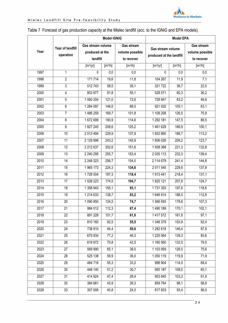
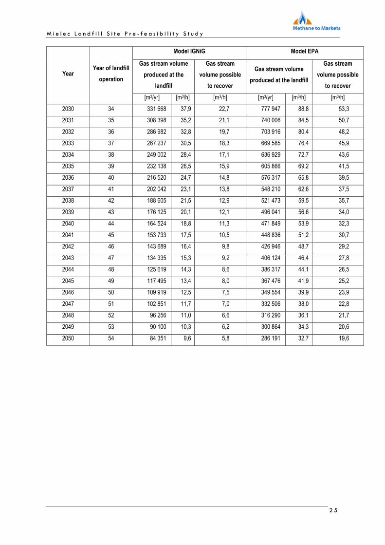
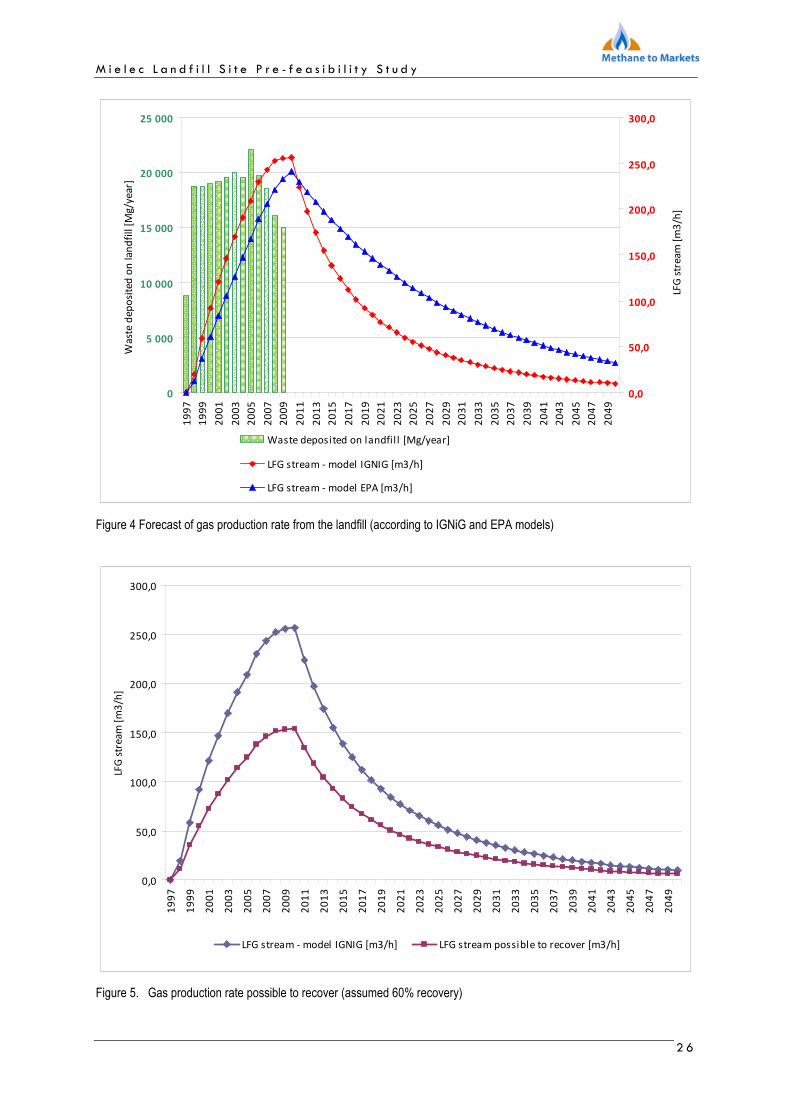
The results of gas production capacity for the Mielec landfill in years 1997 – 2050 was summarized in
Table 7 and Figure 4. Both, table and figure show also calculations of a gas flux volume that would be
possible to recover. It should be noted that it is not possible to fully use all the gas volume. Based on
the experts method and professional experience of the engineers from the Oil and Gas Institute it was
assumed that only 60% of the total gas volume estimated in the IGNIG model can be recovered.
2 A – paper, textiles, 3 B – garden, park wastes 4 C – organic waste (food, wastes from the wastewater treatment plants) 5 D – wood chips 6 E – inert and inorganic wastes (glass, metals, debris)
A2 B3 C4 D5 E6
17,0 % 5,0 % 25,0 % 3,0 % 50,0 %
M i e l e c L a n d f i l l S i t e P r e - f e a s i b i l i t y S t u d y
2 4
Table 7 Forecast of gas production capacity at the Mielec landfill (acc. to the IGNiG and EPA models).
Model IGNiG Model EPA
Gas stream volume
produced at the
landfill
Gas stream
volume possible
to recover
Gas stream volume
produced at the landfill
Gas stream
volume possible
to recover
Year Year of landfill
operation
[m3/yr] [m3/h] [m3/h] [m3/yr] [m3/h] [m3/h]
1997 1 0 0,0 0,0 0 0,0 0,0
1998 2 171 714 19,6 11,8 104 267 11,9 7,1
1999 3 512 743 58,5 35,1 321 722 36,7 22,0
2000 4 803 977 91,8 55,1 528 571 60,3 36,2
2001 5 1 060 204 121,0 72,6 728 947 83,2 49,9
2002 6 1 284 097 146,6 88,0 921 002 105,1 63,1
2003 7 1 486 259 169,7 101,8 1 108 208 126,5 75,9
2004 8 1 672 699 190,9 114,6 1 292 181 147,5 88,5
2005 9 1 827 245 208,6 125,2 1 461 629 166,9 100,1
2006 10 2 013 494 229,9 137,9 1 652 860 188,7 113,2
2007 11 2 129 996 243,2 145,9 1 806 026 206,2 123,7
2008 12 2 212 637 252,6 151,6 1 938 368 221,3 132,8
2009 13 2 240 295 255,7 153,4 2 035 113 232,3 139,4
2010 14 2 248 323 256,7 154,0 2 114 679 241,4 144,8
2011 15 1 965 173 224,3 134,6 2 011 545 229,6 137,8
2012 16 1 728 004 197,3 118,4 1 913 441 218,4 131,1
2013 17 1 528 223 174,5 104,7 1 820 121 207,8 124,7
2014 18 1 358 943 155,1 93,1 1 731 353 197,6 118,6
2015 19 1 214 633 138,7 83,2 1 646 914 188,0 112,8
2016 20 1 090 850 124,5 74,7 1 566 593 178,8 107,3
2017 21 984 012 112,3 67,4 1 490 189 170,1 102,1
2018 22 891 228 101,7 61,0 1 417 512 161,8 97,1
2019 23 810 160 92,5 55,5 1 348 379 153,9 92,4
2020 24 738 910 84,4 50,6 1 282 618 146,4 87,9
2021 25 675 934 77,2 46,3 1 220 064 139,3 83,6
2022 26 619 972 70,8 42,5 1 160 560 132,5 79,5
2023 27 569 990 65,1 39,0 1 103 959 126,0 75,6
2024 28 525 138 59,9 36,0 1 050 119 119,9 71,9
2025 29 484 716 55,3 33,2 998 904 114,0 68,4
2026 30 448 140 51,2 30,7 950 187 108,5 65,1
2027 31 414 924 47,4 28,4 903 845 103,2 61,9
2028 32 384 661 43,9 26,3 859 764 98,1 58,9
2029 33 357 006 40,8 24,5 817 833 93,4 56,0
M i e l e c L a n d f i l l S i t e P r e - f e a s i b i l i t y S t u d y
2 5
Model IGNiG Model EPA
Gas stream volume
produced at the
landfill
Gas stream
volume possible
to recover
Gas stream volume
produced at the landfill
Gas stream
volume possible
to recover
Year Year of landfill
operation
[m3/yr] [m3/h] [m3/h] [m3/yr] [m3/h] [m3/h]
2030 34 331 668 37,9 22,7 777 947 88,8 53,3
2031 35 308 398 35,2 21,1 740 006 84,5 50,7
2032 36 286 982 32,8 19,7 703 916 80,4 48,2
2033 37 267 237 30,5 18,3 669 585 76,4 45,9
2034 38 249 002 28,4 17,1 636 929 72,7 43,6
2035 39 232 138 26,5 15,9 605 866 69,2 41,5
2036 40 216 520 24,7 14,8 576 317 65,8 39,5
2037 41 202 042 23,1 13,8 548 210 62,6 37,5
2038 42 188 605 21,5 12,9 521 473 59,5 35,7
2039 43 176 125 20,1 12,1 496 041 56,6 34,0
2040 44 164 524 18,8 11,3 471 849 53,9 32,3
2041 45 153 733 17,5 10,5 448 836 51,2 30,7
2042 46 143 689 16,4 9,8 426 946 48,7 29,2
2043 47 134 335 15,3 9,2 406 124 46,4 27,8
2044 48 125 619 14,3 8,6 386 317 44,1 26,5
2045 49 117 495 13,4 8,0 367 476 41,9 25,2
2046 50 109 919 12,5 7,5 349 554 39,9 23,9
2047 51 102 851 11,7 7,0 332 506 38,0 22,8
2048 52 96 256 11,0 6,6 316 290 36,1 21,7
2049 53 90 100 10,3 6,2 300 864 34,3 20,6
2050 54 84 351 9,6 5,8 286 191 32,7 19,6
M i e l e c L a n d f i l l S i t e P r e - f e a s i b i l i t y S t u d y
2 6
0
5 000
10 000
15 000
20 000
25 000
19
97
19
99
20
01
20
03
20
05
20
07
20
09
20
11
20
13
20
15
20
17
20
19
20
21
20
23
20
25
20
27
20
29
20
31
20
33
20
35
20
37
20
39
20
41
20
43
20
45
20
47
20
49
Wa
ste
de
po
site
d o
n l
an
dfi
ll [
Mg
/ye
ar]
0,0
50,0
100,0
150,0
200,0
250,0
300,0
LFG
str
eam
[m
3/h
]
Waste deposited on landfil l [Mg/year]
LFG stream - model IGNIG [m3/h]
LFG stream - model EPA [m3/h]
Figure 4 Forecast of gas production rate from the landfill (according to IGNiG and EPA models)
0,0
50,0
100,0
150,0
200,0
250,0
300,0
19
97
19
99
20
01
20
03
20
05
20
07
20
09
20
11
20
13
20
15
20
17
20
19
20
21
20
23
20
25
20
27
20
29
20
31
20
33
20
35
20
37
20
39
20
41
20
43
20
45
20
47
20
49
LFG
str
ea
m [
m3
/h]
LFG stream - model IGNIG [m3/h] LFG stream possible to recover [m3/h]
Figure 5. Gas production rate possible to recover (assumed 60% recovery)

M i e l e c L a n d f i l l S i t e P r e - f e a s i b i l i t y S t u d y
2 7
6. Systems of landfill gas extraction
In the report the most popular technologies used for gas extraction from the landfill have been
presented, and the best method for the Mielec municipal landfill has been selected. The proposed
system of landfill gas extraction at the Mielec landfill is based on the analysis of gas characteristic and
calculations of the expected gas production. At the same time, it was assumed, that is possible to
recover only 60% of the total gas volume estimated by the IGNIG model (chapter 5 ).
6.1 Description of the gas extraction technology
The installation for gas extraction from the municipal solid waste landfill consists of the following
elements:
• Elements venting gas from the landfill bed (vertical wells and horizontal pipes)
• Header pipes discharging gas to the collection point (collection station)
• Collection station (demoisturizers, blower, measuring/performance monitoring equipment)
from the collection station the landfill gas is transported to an utilization unit (burner, electricity
generation).
6.1.1 Elements of installation for gas extraction
Vertical gas extraction system - wells
Newly constructed municipal solid waste landfills have their extraction wells built on the layer of soil
planted directly on a geomembrane, which serves as an additional landfill lining (Photo 4). This way
a unit stress of well on a geomembrane can be reduced and a landfill lining is not damaged. Solid
wastes are deposited and compacted around wells, which are spaced every 30 – 50 m. At the lower
part of the well a filter is mounted. A horizontal header pipe running from the filter discharges leachate
to the collection well. A gas extraction well has its filter made as a slotted 100 - 200 mm diameter pipe.
Pipe length is 2 m and it can be further extended once the landfill gets filled up. The well is protected by
a 1m diameter steel pipe; pipe length 2,5 - 5,0 m). A space between a filter and well cover is filled with
gravel and cover with a sealing ring. The well cover is gradually extended and the extra space made up
with gravel once the landfill expands. The upper part of the filter is made from a non-perforated pipe.
M i e l e c L a n d f i l l S i t e P r e - f e a s i b i l i t y S t u d y
2 8
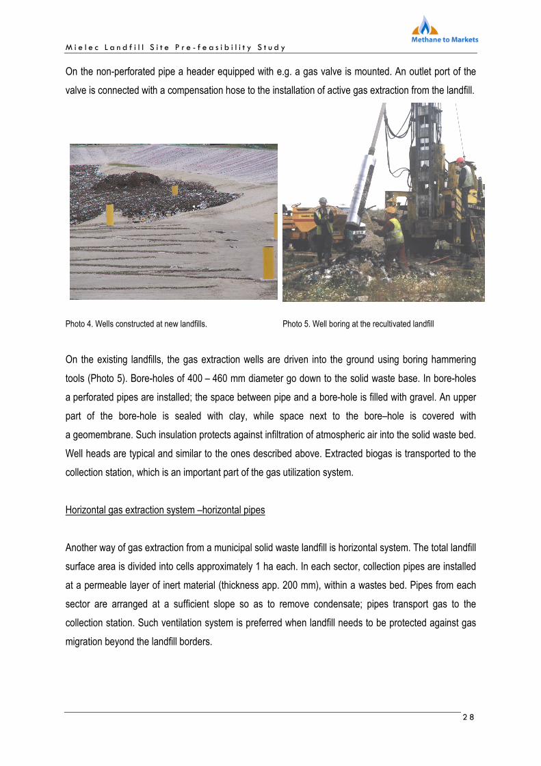
On the non-perforated pipe a header equipped with e.g. a gas valve is mounted. An outlet port of the
valve is connected with a compensation hose to the installation of active gas extraction from the landfill.
Photo 4. Wells constructed at new landfills. Photo 5. Well boring at the recultivated landfill
On the existing landfills, the gas extraction wells are driven into the ground using boring hammering
tools (Photo 5). Bore-holes of 400 – 460 mm diameter go down to the solid waste base. In bore-holes
a perforated pipes are installed; the space between pipe and a bore-hole is filled with gravel. An upper
part of the bore-hole is sealed with clay, while space next to the bore–hole is covered with
a geomembrane. Such insulation protects against infiltration of atmospheric air into the solid waste bed.
Well heads are typical and similar to the ones described above. Extracted biogas is transported to the
collection station, which is an important part of the gas utilization system.
Horizontal gas extraction system –horizontal pipes
Another way of gas extraction from a municipal solid waste landfill is horizontal system. The total landfill
surface area is divided into cells approximately 1 ha each. In each sector, collection pipes are installed
at a permeable layer of inert material (thickness app. 200 mm), within a wastes bed. Pipes from each
sector are arranged at a sufficient slope so as to remove condensate; pipes transport gas to the
collection station. Such ventilation system is preferred when landfill needs to be protected against gas
migration beyond the landfill borders.

M i e l e c L a n d f i l l S i t e P r e - f e a s i b i l i t y S t u d y
2 9
Vertical-horizontal collection system
Some landfills use installations consisting of both vertical gas wells and perforated horizontal pipes.
Such collection method is often used at the landfills with a thick layer of solid wastes. Horizontal pipes
are connected with vertical wells at numerous levels to facilitate the gas discharge to the well. Such
option has also some economic advantages reducing a number of wells.
6.1.2 Connection of elements of a landfill gas extraction installation.
Gas extraction wells and horizontal pipes can be connected in one of two ways.
Individual headers
Individual headers require that there is a single pipe running directly from each well (or a horizontal
header) to the gas collection station. The basic advantage of a direct connection between gas
extraction wells and the collection station is a possibility of regulation of all wells at single spot. The
most popular are Ф 50 - 63 mm pipes. The drawbacks of this solution include possible siphoning and
some problems with a gas flow. The operational problems appear mostly when pipes have not been
placed properly.
Collective headers
In collective headers particular wells and horizontal headers are connected to the main headers, which
supply gas to the collection station. Gas extraction wells are linked to few collective headers of Ф 100 -
160 mm diameter most frequently at the landfills with a large surface area. The main advantage of such
construction is easy removal of condensate due to a better gas line capacity; there is no need for
intermediate driplegs between the well and the collection station. On the other hand, regulation of gas
extraction from the landfill becomes more troublesome, since the shut/adjustment valves are installed at
the heads of wells located all over the landfill area.

M i e l e c L a n d f i l l S i t e P r e - f e a s i b i l i t y S t u d y
3 0
6.2. Proposal of gas extraction at the Mielec municipal solid waste landfill
The proposal of gas extraction at the Mielec municipal solid waste landfill has been prepared based on
the data provided by the Zakładu Utylizacji Odpadów Komunalnych Spółka z o.o. w Mielcu.
Prior construction of the gas extraction installation recultivation of the landfill is required, including
banks reinforcing slopes.
At the Mielec landfill, the authors propose a gas extraction installation that consists of vertical gas
extraction wells with an individual connection to the gas collection station. Such configuration facilitates
flexible and easy to stage project realization.
6.2.1 Drilling
Drilling jobs have to be limited to the depth of 2 m below the ground level to avoid damage of
gheomebranes that secure the landfill base. Drilling works have to be performed under professional
supervision and according to the previously prepared guidelines on health and safety measures. The
staff has to observe all instructions concerning work at the hazardous conditions and exposition to
gases extracted from the landfill (methane, carbon dioxide, carbon oxide, hydrogen sulphide).
6.2.2 Construction of the gas extraction well
Construction of 8 gas extraction wells is proposed at the Mielec municipal solid waste landfill. The wells
shall be drilled as holes of diameter of 0,45 m - 1 m and the depth as stated in the chapter 6.2.1. The
wells depth has to be carefully measured in order to protect a protective lining of the landfill base. Bore-
holes should be spaced every 25 – 50 m to keep a minimum distance (15 m) from the landfill
embankment. Perforated PEHD pipes (filter of 100-200 mm diameter) are placed in the center of the
bore-holes. Space between a filter and bore-hole walls shall be filled with a filtering medium (coarse
gravel) and sealed from the top with a packer (cylindrical sealing element). The upper part of the filter is
made from a non-perforated pipe. On the non-perforated pipe a header equipped with
a shut/adjustment valve and a measuring port are installed. An outlet port of the valve is connected with
a compensation hose to the installation of active gas extraction system. A PEHD geomembrane of
thickness of from 1.0 mm is spread out around the well at the 5 m radius; it protects a gas extraction
installation from air infiltration. A concrete ring with a steel flap protects the well from the top.

M i e l e c L a n d f i l l S i t e P r e - f e a s i b i l i t y S t u d y
3 1
6.2.3 Gas transport to the collection station
Landfill gas should be extracted from the gas extraction wells through individual PE headers of
Ф 63 mm. The headers have to run at the minimum depth of 1 m under a top of the top cover, at
a slope >1% towards the collection station. Along the header, right after the well, and in the collection
station driplegs should be mounted to collect condensing leachate. The gas pipes and driplegs
locations should be selected during the course of the project, as a part of engineering supervision.
While designing a layout of trenches for the headers, the optimal route should be chosen that
guarantees the shortest distance between wells and the collection station.
6.2.4 Gas Collection Station
The gas collection station should comprise the following units:
• Blowers to extract gas form the landfill;
• Filters to remove solids;
• Reservoirs where condensate is removed from the gas;
• Instruments for control of gas extraction and transport ;
• Measuring & control equipment.
The pipes discharging gas from the gas extraction wells are connected to the header in the collection
station. Ahead of the header a shut valve and a measuring/sampling port should be instaled on every
pipe; the valve is used for flow adjustments. On the header a condensate trap should be mounted. The
station should be located under a shelter or even in the container (if it is possible). A layout of a typical
gas collection station is presented in Figure 5.
Figure 5. Layout of a gas collection station.
Landfill gas to gas engine unit energetycznego
Leachate discharge
1
2
3
1 Shut/adjustment valves and a measuring port 2 Header ø 110 3 Condensate trap

M i e l e c L a n d f i l l S i t e P r e - f e a s i b i l i t y S t u d y
3 2
7. Utilization and reuse of landfill gas
7.1 Landfill gas utilization
According to the UE regulations, it is the owner of the municipal solid waste landfill that is responsible
for intake and utilization of landfill gas. There are many ways of thermal utilization of landfill gas, they
include:
• Burning in a flare,
• Direct use,
• Electricity generation,
• Electricity/heat generation
• Production of gas similar to natural gas,
The most promising methods are the ones that involve energy generation.
Burning in a flare
Burning of gas in a flare reduces green house gas emission, odors, and facilitates control of gas
migration beyond the landfill site. Such solution is recommended mostly at the landfills where gas
generation is not sufficient to produce electricity or where there is no need for heat generation.
Direct use
Landfill gas can be burned directly at the site in hot water or steam boilers (equipped with special
burners) or in neighboring houses or other facilities located outside the landfill. Long-distance gas, hot
water or steam transport is rather complicated from a technical point of view, and quite often not cost
effective. Municipal solid waste landfills are usually located away from residential housings and
industrial plants. However, in locations where there is no need of a long –distance transport of gas or
energy a direct use should be recommended. This option requires only construction of a boiler house
and a gas desulphurization installation (if gas contains sulphur).
Another way of a direct use of landfill gas is its technological application e.g. in brick and lime furnaces.
Landfill gas may also be used as a fuel for systems based on infrared radiators.

M i e l e c L a n d f i l l S i t e P r e - f e a s i b i l i t y S t u d y
3 3
Electricity generation
Another option of landfill gas generation is a generation of electricity in power generation units with
piston motors. Present technical solutions seem to promote electricity generation. Also a possible
investment costs return due to energy sale and possibility to obtain the Energy Certificates of Origin
and following property rights („green certificates”) promote energy generation from the LFG. The main
constrains of this solution is low electric efficiency ranging between 30-37 %.
Electricity and heat cogeneration (CHP)
Systems of simultaneous generation of both electricity and useful heat are used when both these
medium are in demand. Electricity can be easily transformed into other more useful energy forms,
therefore such cogeneration units should be preferred in a location where heat is in demand. The basic
factor that determines a possible cogeneration application is a constant and sufficiently large heat
demand. Cogeneration of heat and electricity in systems with a small power output is performed mostly
in combustion engines and gas turbines. Both these machines use energy produced in a combustion
process to drive an energy generator. Heat exchangers trap the produced heat, which is used for hot
water production.
Production of gas similar to natural gas.
From the technological point of view the most challenging option of landfill gas utilization is its
transformation into a gas similar to a natural gas. Gas enrichment process consists of: removal of
water, carbon dioxide and some other pollutants present in the amount of less then 1 % [v/v]. If gas
parameters become similar to a high-methane gas, it may be supplied to a distribution network. The
process is cost efficient only if the volume of gas generated at the landfill site is high.
Human and environmental protection perspective suggests gas extraction and utilization throughout the
entire period of its generation. The use of gas for energy production is possible for a much shorter time
period of 10 - 15 years. Hence, developing of the prospective gas production prognosis and its
continuous verification seems to be the crucial factor that decides about selection of the gas utilization
option.

M i e l e c L a n d f i l l S i t e P r e - f e a s i b i l i t y S t u d y
3 4
7.2 Proposal of gas utilization at the Mielec landfill
After analysis of all possible methods of landfill gas utilization the option of electricity production was
found the as the most profitable.
The data provided by the ZUOK Sp. z o.o. w Mielcu, concerning the solid waste and the landfill closure
time as well as gas characteristic analysis performed by INiG at the landfill in September 2009 indicate
that it is very likely that pumping test will confirm the calculated ( in chapter 5) landfill gas productivity of
the landfill. Taking into account seasonal fluctuations of gas quantity and quality, an electric power
generation unit of 142 kW should be installed at the Mielec landfill.
8. Simplified economic analysis of the proposed option of landfill gas intake and utilization
To perform the analysis at first a „life time” of the project has to be determined. In our case, the time of
project realization is determined by a gas stream volume generated at the landfill per year. According to
the proposal (see chapter. 7.2) the 142 kWe electricity generator is recommended; its consumption of
gas with a 50% methane content by volume is:
total power (100%) = 142 kW 84 Nm3/h
nominal power (50%) = 71 kW 42 Nm3/h
Taking into consideration the above assumptions as well as the value of the minimum load of the
generator (50% of the nominal power - gas consumption 42 m3/h) and Table 7 of the report it can be
concluded that year 2020 would be the last year of the project.
Assuming that the construction of the installation would take one year (2010) energy production is
planned to start in year 2011.
Summarizing, the project life time is 10 years.
8.1 Investment costs and the proposed project schedule
Table 8 presents the proposed schedule of project implementation and its cost structure. The project
includes landfill gas extraction and its utilization for electricity production.

M i e l e c L a n d f i l l S i t e P r e - f e a s i b i l i t y S t u d y
3 5
Table 8. Schedule of the LFG extraction and utilization for electricity production.
PHASE TASK RANGE Cost [PLN]
I
1 Technical project including: • location of gas extraction wells; • routes of collection headers; • detailed characteristics of elements of a gas extraction installation.
25 000
II 1 2
Drilling and assembly of 8 gas extraction wells Assembly of appurtenances at gas extraction wells
130 000 24 000
III 1 Tests of an active gas discharge for each individual well (verification of the gas
production prognosis prepared with mathematical models). 25 000
IV
1
2 3
Construction of an individual collection headers connecting gas extraction wells with the gas collection station. Construction of the gas collection station Test of degassing of gas wells
85 000 100 000 20 000
V 1 Selection and purchase of equipment for preliminary gas treatment (drying
and cleaning) and a flare for excess gas burning. 40 000
VI
1
2 3
Selection and purchase of a unit for energy generation from landfill gas (container-type 142 kWe electricity generator) Gas connection to an energy generator Connection to the power source
1 100 000 30 000 70 000
Total investment costs: 1 649 000 PLN
Before the wells are connected to the common header tests of an active gas discharge have to be
performed. The tests help to determine actual capacity of the particular cells at the landfill. Then the
wells should be connected to the gas collection station. The following phase comprises performing of
the overall degassing test using a blower installed in the collection station. The test should be carried
on for a couple of days, under a supervision of the qualified staff that is familiar with hazardous jobs and
has sufficient experience in operation of landfill gas installations. The results of the test may serve as
an argument in the final decision about the size of the energy generation unit.
8.2 Project operational costs
The basic operational costs include:
• personnel costs- two more people have to be employed. A gross monthly pay is 2500 PLN per
person; total annual cost is 60 000 PLN. Additionally, an annual 1,5 % increase of pay is
assumed, if compared with a previous year,
• operation cost of the energy generator (service, oil exchange, exchange of cooling fluid and
worn parts). It is assumed 40 000 PLN during of the first operation year. Additionally, an annual
1,5 % increase of the operational cost is assumed.
M i e l e c L a n d f i l l S i t e P r e - f e a s i b i l i t y S t u d y
3 6
8.3 Revenues during the project implementation
To determine the expected revenues obtained during the project implementation the quantity of the
generated energy has to be calculated.
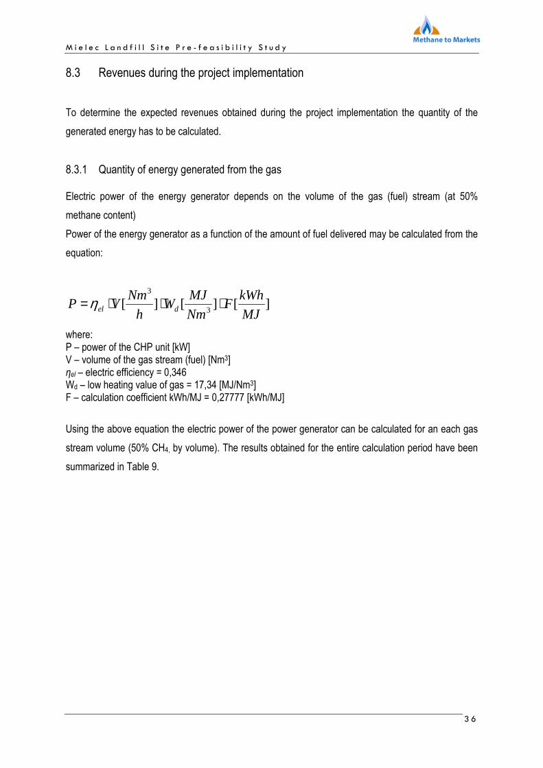
8.3.1 Quantity of energy generated from the gas Electric power of the energy generator depends on the volume of the gas (fuel) stream (at 50%
methane content)
Power of the energy generator as a function of the amount of fuel delivered may be calculated from the
equation:
][][][3
3
MJ
kWhF
Nm
MJW
h
NmVP del ⋅⋅⋅=η
where: P – power of the CHP unit [kW] V – volume of the gas stream (fuel) [Nm3] ηel – electric efficiency = 0,346 Wd – low heating value of gas = 17,34 [MJ/Nm3] F – calculation coefficient kWh/MJ = 0,27777 [kWh/MJ]
Using the above equation the electric power of the power generator can be calculated for an each gas
stream volume (50% CH4, by volume). The results obtained for the entire calculation period have been
summarized in Table 9.

M i e l e c L a n d f i l l S i t e P r e - f e a s i b i l i t y S t u d y
3 7
Table 9 Electric power of the energy generator as a function of a landfill gas stream volume ( 50% CH4 content, by volume).
Year
Gas volume at 50% CH4 content, by volume;
Column 5 Table 7 [Nm3/h]
Power [%]
Power [kW]
2011 134,6 100* 142,0
2012 118,4 100* 142,0
2013 104,7 100* 142,0
2014 93,1 100* 142,0
2015 83,2 98 138,7
2016 74,7 88 124,5
2017 67,4 79 112,3
2018 61,0 72 101,7
2019 55,5 65 92,5
2020 50,6 59 84,3
* - nominal power of the generator.
To calculate an annual supply of electric energy the following assumptions have been made:
• The annual power of the energy generator as in table 9.
• Availability of the unit. Power generators are usually selected so as to operate for the maximum
number of hours per day. Such operation regime is related directly to the economic efficiency of
the project. Apart from the planned shut-downs (service break, planned repairs), operation time
depends on the system reliability. The availability of the unit guaranteed by the manufacturer
remains within the range from 90 to 95 %. It considers both planned shut-downs and
unexpected failures. The values presented above are assigned to the system supplied with a
natural gas. In case of landfill gas availability of the power generation unit drops down due to a
higher content of fuel contaminates responsible for e.g. corrosion of motor elements, such as:
hydrogen sulphide, organic silica compounds, organic sulphur compounds, organic compounds
of chlorine and fluorine. Taking into account the above comments, availability of the produced
energy was assumed at the level of approximately 91 %. Therefore, each year the operation
time of the power generation unit is 8000 hours.
The calculation results of the electricity produced for the entire analyzed period are presented in
Table 10.
M i e l e c L a n d f i l l S i t e P r e - f e a s i b i l i t y S t u d y
3 8
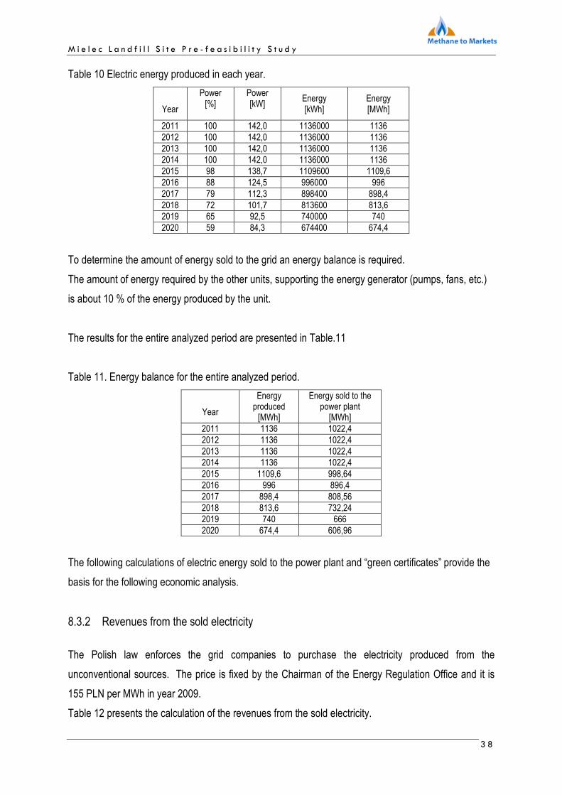
Table 10 Electric energy produced in each year.
Year
Power [%]
Power [kW]
Energy [kWh]
Energy [MWh]
2011 100 142,0 1136000 1136 2012 100 142,0 1136000 1136 2013 100 142,0 1136000 1136 2014 100 142,0 1136000 1136 2015 98 138,7 1109600 1109,6 2016 88 124,5 996000 996 2017 79 112,3 898400 898,4 2018 72 101,7 813600 813,6 2019 65 92,5 740000 740 2020 59 84,3 674400 674,4
To determine the amount of energy sold to the grid an energy balance is required.
The amount of energy required by the other units, supporting the energy generator (pumps, fans, etc.)
is about 10 % of the energy produced by the unit.
The results for the entire analyzed period are presented in Table.11
Table 11. Energy balance for the entire analyzed period.
Year
Energy produced
[MWh]
Energy sold to the power plant
[MWh] 2011 1136 1022,4 2012 1136 1022,4 2013 1136 1022,4 2014 1136 1022,4 2015 1109,6 998,64 2016 996 896,4 2017 898,4 808,56 2018 813,6 732,24 2019 740 666 2020 674,4 606,96
The following calculations of electric energy sold to the power plant and “green certificates” provide the
basis for the following economic analysis.
8.3.2 Revenues from the sold electricity
The Polish law enforces the grid companies to purchase the electricity produced from the
unconventional sources. The price is fixed by the Chairman of the Energy Regulation Office and it is
155 PLN per MWh in year 2009.
Table 12 presents the calculation of the revenues from the sold electricity.

M i e l e c L a n d f i l l S i t e P r e - f e a s i b i l i t y S t u d y
3 9
Table 12. Revenues from the sold electricity for the entire analyzed period.
Year
Electricity sold to the grid
[MWh]
Revenues [PLN]
2011 1022,4 158 472 2012 1022,4 158 472 2013 1022,4 158 472 2014 1022,4 158 472 2015 998,64 154 789 2016 896,4 138 942 2017 808,56 125 327 2018 732,24 113 497 2019 666 103 230 2020 606,96 94 079
8.3.3 Revenues from the „green certificates”
According to the Polish law, if the investor generates the electricity from the unconventional sources, he
receives the additional assistance in a form of “the Energy Certificates of Origin”. Such certificates can
be sold at the energy commodity market. The certificates are issued based on the amount of produced
energy. In year 2009 the average price of the „green certificate” is 255 PLN/MWh.
Calculation of the revenues from „the green certificates” are summarized in Table 13.
Tabela 13. Revenues from “the green certificates” for the entire analyzed period.
Year
Amount of electricity sold to
the grid [MWh]
Revenues [PLN]
2011 1022,4 260 712 2012 1022,4 260 712 2013 1022,4 260 712 2014 1022,4 260 712 2015 998,64 254 653 2016 896,4 228 582 2017 808,56 206 183 2018 732,24 186 721 2019 666 169 830 2020 606,96 154 775
8.4 Calculation of NPV i IRR.
The simplified economic analysis was based on calculation of NPV and IRR.
Net Present Value (NPV) is a the sum of all cash flows discounted at the starting moment of the whole
project. The cash flow covers all the incomes and expenses spend during the construction and
M i e l e c L a n d f i l l S i t e P r e - f e a s i b i l i t y S t u d y
4 0
operation of the project. The project is economically sound if NPV > 0; the highest NPV value indicates
the best project.
The NPV value can be calculated in the following way:
∑∑∑ +=
+⋅=⋅=
tt
ttt r
CF
rCFaCFNPV
)1()1(
1
where:
NPV – net present value; sum of discounted cash flows.
CFt – cash flow in a given year „t”,
t – year of the project
a – discount coefficient, which calculates the present value of the future cash flows, expressed by
formula:
tra
)1(
1
+=
r – discount rate, generally equals to the bank deposit interests.
IRR - internal rate of return is a discount rate, at which the present value of all incomes is equal to the
present value of all the expenses covered at the construction and operation stages. IRR is expressed in
% and reflexes the speed, at which project returns exceed the expenses.
In other words, IRR is a discount rate at which NPV is 0. The formula for IRR can be presented as
follows:
∑=
=+
⋅n
itt IRR
CF1
0))1(
1(
where:
CFt - difference between the revenues and expenses in year t,
n – number of year.
To calculate NPV and IRR some assumptions concerning the macroeconomics and a tax system are
required.

M i e l e c L a n d f i l l S i t e P r e - f e a s i b i l i t y S t u d y
4 1
Assumptions for the calculations:
1. Operation period - 10 years.
2. The installation operates 8000 hrs per year.
3. Investments are covered in 50% by the investor and in 50% by a credit from the National Fund
of Environmental Protection. The interest rate of the credit is 0,9 of a bill discount rate. On 1-st
of October 2009 a discount rate for the bills was 3,75% so the discount value for the analysis
was 3,375%. It is assumed that the discount rate is constant during the whole period of
analysis (10 years).
4. Operating costs increase 1.5% y/y.
5. It is assumed that the investment is undertaken by the landfill owner. That means zero
purchasing cost of the landfill gas during the entire 10 years of analysis.
6. The construction face of the project is less then one year. All the expenses are scheduled in
year 0.
7. The electricity is sold to the grid at the fixed price 155 PLN/MWh.
8. The price for green certificates is 255 PLN/MWh.
9. The accelerated depreciation with the yearly rate 10% and accelerating coefficient 1,7 is
assumed for the analysis. To simplify the calculations only one depreciation rate was assumed
for all the elements of the installation.
10. The income tax from the sale of electricity and green certificates is 19%.
11. Both a liquidation value and a book value are zero at the end of the project.
12. Discount rate is 10%.
The simplified economic analysis of the energy production from the landfill gas shows positive values
for the NPV and IRR. The project looks feasible.
The main parameters are:
NPV: 139 733 zł
IRR: 14,78 %.
Results and details of the analysis are presented table 14.
It has to be emphasized that the calculations were carried out based on the data from the literature and
from the other projects. Once the decision about starting the investment is made, the calculations have
to be repeated based on the actual and specific for this project cost estimates.

M i e l e c L a n d f i l l S i t e P r e - f e a s i b i l i t y S t u d y
4 2
Table 14. Results of the simplified economic analysis.
Year of project realization 0 1 2 3 4 5 6 7 8 9 10
No. Year 2010 2011 2012 2013 2014 2015 2016 2017 2018 2019 2020
1 Reveues from sale of: 0 419 184 419 184 419 184 419 184 409 442 367 524 331 510 300 218 273 060 248 854
a Electricity 0 158472 158472 158472 158472 154789,2 138942 125326,8 113497,2 103230 94078,8
b Ggreen certificates 0 260712 260712 260712 260712 254653,2 228582 206182,8 186721,2 169830 154774,8
2
Operating costs and financial costs 0 408 157 359 218 318 403 288 947 287 732 286 542 285 375 284 233 236 592 117 121
a Operating costs 0 100 000 101 500 103 023 104 568 106 136 107 728 109 344 110 984 112 649 114 339
b Depreciasion 0 280 330 232 674 193 119 164 900 164 900 164 900 164 900 164 900 118 377 0
d Credit interests 0 27 827 25 044 22 262 19 479 16 696 13 913 11 131 8 348 5 565 2 783
3 Income before tax 0 11 027 59 966 100 781 130 237 121 710 80 982 46 135 15 986 36 468 131 732
4 Income (tax 19%) 0 8 932 48 572 81 632 105 492 98 585 65 596 37 369 12 949 29 539 106 703
5 Depreciasion 0 280 330 232 674 193 119 164 900 164 900 164 900 164 900 164 900 118 377 0
6 Capital instalment 0 -82 450 -82 450 -82 450 -82 450 -82 450 -82 450 -82 450 -82 450 -82 450 -82 450
7 Inwestments -1 649 000 0 0 0 0 0 0 0 0 0 0
8 Credit 824 500 0 0 0 0 0 0 0 0 0 0
9 Cash flow -824 500 206 812 198 796 192 302 187 942 181 035 148 046 119 819 95 399 65 466 24 253
10 Discounting coeficient 1 0,909 0,826 0,751 0,683 0,621 0,564 0,513 0,467 0,424 0,386
11 Discounted cash flow -824 500 188 011 164 294 144 479 128 367 112 409 83 568 61 486 44 504 27 764 9 351
12
Accumulated discounted cash flows -824 500 -636 489 -472 195 -327 716 -199 348 -86 940 -3 372 58 114 102 618 130 382 139 733

M i e l e c L a n d f i l l S i t e P r e - f e a s i b i l i t y S t u d y
4 3
9. Summary
The projects involving landfill gas recovery for energy focus usually on generation on electric energy (or
electricity and heat generation - CHP). As such they should be carefully analyzed from both energy and
economic viewpoint including a time perspective. Gas productivity of the municipal solid waste landfill
after its closure decreases in time, reducing amount of available chemical energy (gas volume stream)
that can be transformed into electricity and heat.
The simplified economic analysis presented in the report provides evidence that it is feasible to start the
project that tries to generate electric energy from the landfill gas extracted from the Mielec municipal
solid waste landfill. The analysis has been performed based on the very conservative assumptions
concerning:
• gas productivity – it was assumed that gas recovery from the landfill comprises 60 % of the flux
calculated with the IGNIG model;
• methane content in landfill gas – it was assumed that the average methane content is 50 % , by
volume. The actual average methane content in gas is about 60 %, by volume; it should remain
at this level throughout the entire methogenesis once the extraction proceeds properly.
• power generation unit output is 142 kWe. Prognosis of gas production for years 2011 – 2013
may indicate that a larger unit may be required. Unfortunately, in a longer perspective the
larger unit may face a reduced gas production rate coming from the landfill and afterwards a
shorter „project life time”. Such situation has a direct impact on the values of parameters NPV
and IRR; they both become negative.
• Average price of “the green certificate” - 255 PLN/MWh. The present value is 271 PLN/MWh
and it is increasing continuously.
• 10 % discount rate. It is a relatively high value, if compared to projects co-financed with the EU
funds, where a discount rate should be at the level of 7-8 %. A 10 % discount rate gives
possibility of reduction of the investment risk.
It should be pointed out that the analysis has been performed based on the assumption that the project
receives investment funds in a form of a low-rate loan granted by the NFOŚiGW. According to the
Rules of financing of pro-ecological projects by the NFOŚiGW, such a loan may be partially remitted. In
such case, investment profitability would increase.

M i e l e c L a n d f i l l S i t e P r e - f e a s i b i l i t y S t u d y
4 4
A substantial improvement of project profitability may be achieved by incorporation of a part of
investment into financing of landfill recultivation. In this case construction of gas extraction wells and
collective headers would be financed from the funds allocated for landfill recultivation.

M i e l e c L a n d f i l l S i t e P r e - f e a s i b i l i t y S t u d y
4 5
10. Literature
[1] „Dokumentacja do wniosku o zmianę pozwolenia dla instalacji do składowania odpadów, z wyłączeniem odpadów obojętnych, o zdolności przyjmowania ponad 10 ton odpadów na dobę zakładu Utylizacji Odpadów Komunalnych Sp. z o.o. w Mielcu przy ulicy wolności 171”; Mielec czerwiec 2009.
[2] P. Klimek i in.; „Analiza dostępnych modeli do obliczania produktywności gazowej składowisk odpadów komunalnych”, Praca statutowa INiG, Kraków 2008.
[3] J. Zaleska-Bartosz; „Zunifikowana metodyka pomiarów składu i emisji biogazu w celu weryfikacji prognozy produktywności gazowej na składowiskach odpadów komunalnych”, Praca statutowa INiG, Kraków 2006
[4] P. Klimek i in; „Heterogeniczność obszarowa produktywności gazowej złoŜa odpadów komunalnych”, Praca statutowa INiG. Kraków 2007
[5] United States Environmental Protection Agency; Landfill Gas Emission Model (Landgem) User’s Guide; http://www.epa.gov/ttncatc1/dir1/landgem-v302-guide.