miee - chapter 26 high and low voltage distribution system
TRANSCRIPT

MIEE - Chapter 26 High and Low Voltage Distribution System Requirements
MIEE 2011, Amend 3 – 1 June 2018 Chapter 26 – HV & LV Systems Page 1 of 55
CHAPTER 26
BACKGROUND
26.1 This policy sets out the Defence technical performance and compliance requirements for the planning, design, equipment selection, construction and commissioning for all Defence electrical distribution systems including:
a. High Voltage (HV) and Low Voltage (LV) electrical distribution cabling systems;
b. Distribution Substations;
c. Distribution Switching Stations;
d. Intake and Primary Substations / Intake and Primary Switching Stations; and
e. Associated ancillary systems, such as distribution system monitoring and control.
26.2 Statutory Compliance Requirement: Defence is required to comply with each State and Territory Electricity Safety Act and the Commonwealth WHS Act, all applicable regulations and the associated standards. Where appropriate the policy may advise on specific obligations, however, these are not generally repeated in this policy. This content of this policy is primarily to provide guidance and detailed technical material as necessary to define the Defence performance requirements and standards to be applied that are in addition to the applicable statutory regulations and standards.
26.3 Compliance with the policy will ensure:
a. Defence meets it’s statutory and safety obligations by protecting people, property and the environment in accordance with the minimum compliance requirements above;
b. Adequate availability and reliability of the electricity supply to meet Defence’s capability requirements; and
c. Ability for Defence to effectively manage, operate and maintain its Defence electrical distribution system.
26.4 The policy is applicable to new installations and the alteration, addition or augmentation of existing installations. It is not mandatory to apply this policy retrospectively.
26.5 A lower standard can be applied to temporary works required during the period of construction of a project where:
a. This offers significant cost/time savings for these temporary works,
b. The temporary works meet the applicable statutory standards, and
c. Where this lower standard is accepted by the Defence Electrical Operating Authority / Network Controller.
d. The temporary works are to be removed by the completion of the project.

MIEE - Chapter 26 High and Low Voltage Distribution System Requirements
MIEE 2011, Amend 3 – 1 June 2018 Chapter 26 – HV & LV Systems Page 2 of 55
PERFORMANCE OBJECTIVE
26.6 The objective of this policy is to:
a. facilitate safe and reliable electrical systems;
b. facilitate compliance with the respective statutory obligations, industry installation standards, codes and legislation;
c. provide an adequate degree of fault tolerance to the Defence electrical distribution system and the ability to expediently recover from any such failure. The general principle is to achieve a full alternative high voltage supply to the transformer of all important loads, through switching. Higher reliability may be required for essential and critical loads;
d. ensure standardisation of equipment across an installation to the extent practical to facilitate semi-skilled operation;
e. consider the longer-term planning of the electrical distribution system; and
f. manage the impact of additional loads to ensure no harmful effect or interaction with other installed equipment.
REFERENCED DOCUMENTS
Legislation
26.7 The applicable legislation and the associated regulations, codes of practice and reference standards forming the minimum compliance obligation for Defence electrical distribution systems are listed in Table 1.1 within the Glossary to this Manual.
Other Obligations and Standards
26.8 Other obligations to be met include:
a. Any requirement stipulated under the National Electricity Rules (NER)
b. Any instructions, directions, guidelines issued by the Australian Energy Market Operator (AEMO)
c. The rules and regulations of the relevant Network Service Provider (NSP) including the Service and Installation Rules and respective Connection Agreements.
d. The National Construction Code, NCC of which the Building Code of Australia (BCA) is part of.
Australian Standards
26.9 The following Australian Standards and the associated reference standards form the minimum compliance obligation for Defence electrical distribution systems:
a. AS/NZS 3000 Wiring Rules
b. AS 2067 Substations and high voltage installations exceeding 1 kV a.c.
c. AS/NZS 7000 Overhead Line Design standards.
MIEE - Chapter 26 High and Low Voltage Distribution System Requirements
MIEE 2011, Amend 3 – 1 June 2018 Chapter 26 – HV & LV Systems Page 3 of 55
ENA (Energy Networks Association) Guidelines
26.10 The Energy Networks Association Australia is a national body representing the gas and electricity distribution businesses throughout Australia. Although this body has no formal legislative standing, it is recognised by the electricity distribution industry as the peak body for the development of industry guidelines and standards.
26.11 It is a Defence policy requirement that designers and construction contractors consider, and adopt as appropriate, the ENA Guidelines for Defence electricity distribution systems. Particular attention should be taken in relation to:
a. ENA Doc 001-2008 National Electricity Safety Code
b. ENA Doc 014-2006 National Low Voltage network electrical protection guidelines
c. ENA Doc 015-2006 National guidelines for the prevention of unauthorised access to electricity infrastructure
d. ENA Doc 025-2010 EG-0 Power System earthing guide – Part 1 management principles
e. ENA Doc EG1-2006 Substation Earthing Guide
f. ENA NENS 03-2006 National guidelines for safe access to electrical and mechanical apparatus
g. ENA NENS 04-2006 National guidelines for safe approach distances to electrical and mechanical apparatus
h. ENA NENS 05-2006 - National Fall Protection guidelines for the electricity industry
i. ENA NENS 09-2014 - National Guidelines for the selection, use and maintenance of personal protective equipment for electrical hazards
DEFINITIONS
Secondary Distribution
26.12 The network of cables in the Defence HV system that provides connection to, and between, the distribution substations. These cables are generally arranged in ring mains.
Primary Distribution
26.13 The network of cables in the Defence HV system that provides direct connection between the major HV power distribution nodes. These are major trunk HV cables.
Types of HV Substations and Switching Stations
26.14 For the purpose of this document, the following terms are used for HV substations and switching stations:
a. Substations: where the supply voltage is transformed from one voltage to another. These generally contain HV switching devices and a transformer. In the context of Defence HV installations substations can take one of two forms:
(1) Distribution Substations: Substations that transform to HV distribution voltage (11kV, 22kV etc) to the utilisation voltage (generally 400/230V)
(2) Intake or Primary Substations (ISS or PSS): Substations that transform the incoming voltage from the Network Service Provider (NSP) (or the Network Intake
MIEE - Chapter 26 High and Low Voltage Distribution System Requirements
MIEE 2011, Amend 3 – 1 June 2018 Chapter 26 – HV & LV Systems Page 4 of 55
Station) to the HV distribution voltage used in the Defence HV system. They are usually a source of electrical supply for the secondary distribution.
b. Switching Stations: where HV is switched only. In the context of Defence HV switching stations can take one of two forms:
(1) Distribution Switching Stations: Switching stations that provide connections between various cables of the secondary distribution (eg spur connections on a ringmain).
(2) Intake or Primary Switching Stations (ISS or PSS): Switching stations that provide connections between the incoming voltage from the NSP (or the Network Intake Station) and various cables of the primary distribution. They are usually a source of electrical supply for the secondary distribution.
(3) Network Intake Station (NIS): In some instance, there is a network connection point prior to the ISS which often has to comply with the NSP standards. This switching station shall be designed as Network Intake Station (NIS). Where the NSP has definite requirements these can take precedence over Defence standards for NIS installations.
Substation / Switching Station Construction
26.15 For the purpose of this document, the following terms are used for substation construction:
a. Indoor – where the equipment is located within a building structure.
b. Outdoor – where the equipment is located outdoors, usually in a yard surrounded by a fence.
c. Kiosk – where the equipment is located outdoors within a weatherproof enclosure.
Defence Electrical Distribution System
26.16 The Defence electrical distrubtion system is defined as one which is owned, operated and/or maintained by Defence. Defence is responsible for and liable for the system.
26.17 The Defence electrical distribution system shall be from the agreed point of supply/connection with the NSP through to the point of attachment / point of entry / point of supply at each facility on the Defence establishment.
Network Service Provider (NSP)
26.18 The Network Service Provider (NSP) is the owner and operator of the off-base mains electricity supply network.
FUNDAMENTAL PRINCIPLES
Safe and Compliant Installations
26.19 All works and services associated with the Defence electrical distribution system shall ensure that the system can be constructed, operated, maintained and de-commissioned in a way that is safe, and minimises risk or hazard to persons, property, external organisations, the community or the environment.
26.20 The design, construction, operation and maintenance shall at all times:
a. Be in full compliance with all applicable legislation, regulations and referenced standards; and

MIEE - Chapter 26 High and Low Voltage Distribution System Requirements
MIEE 2011, Amend 3 – 1 June 2018 Chapter 26 – HV & LV Systems Page 5 of 55
b. Adhere to the requirements and obligations set out within the applicable Service and Installation Rules and any NSP connection agreement in effect.
Support Defence’s Capability
The Defence electrical distribution system must ensure the provision of a reliable, stable and secure electricity supply that will support and sustain Defence’s operations and capability with sufficient capacity to meet any future foreseeable needs.
Competent Personnel
26.21 Competent, experienced and appropriately licensed persons shall be engaged to undertake the Defence electrical distribution system’s planning, design, construction, commissioning, operation and maintenance.
Planned and coordinated
26.22 The Defence High Voltage Electrical Master Plan for the Base should be utilised in the ongoing planning and design of the Defence electrical distribution system to avoid expensive rework.
26.23 A Project High Voltage Electrical Development Plan must be prepared for all proposed Defence HV distribution system work. This Development Plan must be agreed by DEEP during the design stage, preferably early.
Standardised and Flexible
26.24 The Defence electrical distribution system shall be designed and constructed such that it will be safe, simple and flexible to operate.
26.25 Where it is safe and practical to do so, the Defence electrical distribution system shall provide for standardised equipment and operation and maintenance practices within each Defence establishment.
26.26 Maintaining the uniformity and consistency of equipment within a Defence site should be considered, subject to them meeting acceptable standards and levels of safety.
Prevention of Unauthorised Access
26.27 The design and construction of the Defence electrical distribution system shall prevent unauthorised access, interference, operation, monitoring and or tampering.
26.28 Access to the Defence electrical distribution system or any part of the Defence electrical distribution system shall only be available to persons authorised by the Base Electrical Operating Authority.
Environmental Obligations
26.29 The Defence electrical distribution system in its planning, design and operation shall comply with Defence’s environmental obligations.
Whole of Life Optimisation
26.30 The design, construction, operation and maintenance of the Defence electrical distribution system shall offer the best whole of life optimisation for Defence.
High Voltage System Outages for New Work
26.31 The staging of the works shall ensure that where an element of the high voltage system is temporarily taken out of service, and this results in a reduction in the levels of redundancy in the system, the duration of the outage is to be as short as practical.
MIEE - Chapter 26 High and Low Voltage Distribution System Requirements
MIEE 2011, Amend 3 – 1 June 2018 Chapter 26 – HV & LV Systems Page 6 of 55
26.32 Under no circumstances shall a Defence high voltage distribution system be left with an open ring, (unable to be reconnected, back fed or an unmovable open point) for greater than one day without prior approval from the site’s Base Services Manager.
26.33 The designer must ensure that the specification includes appropriate requirements and any additional Defence Electrical Operating Authority or Network Controller requirements.
DEFENCE ELECTRICAL OPERATING AUTHORITY / NETWORK CONTROLLER RESPONSIBILITIES
26.34 The Department of Defence, as the owner and user of electrical systems on its establishments, is responsible for their operation. Defence vests the responsibility for technical control and operational safety for the Base electrical distribution system with the Defence Electrical Operating Authority engaged as part of the Base Services, Estate Maintenance & Operations Services (EMOS) Contract. The Defence Electrical Operating Authority appoints a Network Controller who is the authority responsible for the operation of Defence distribution systems.
26.35 The Electrical Operating Authority is responsible for:
a. the configuration and operation of the Base electrical distribution system at all times;
b. regulating access to Defence distribution systems;
c. ensuring the safety of all personnel required to access, work upon or work in close proximity to the Defence electrical distribution system;
d. the continuity of supply from the Defence electrical distribution system;
e. maintaining adequate documentation of the Defence electrical distribution system;
f. accepting and connecting new electrical distribution system infrastructure; and
g. the safety of and maintenance of the plant and equipment in accordance with Base Services contract requirements and all applicable legislation and regulations.
26.36 The Defence Electrical Operating Authority / Network Controller has the right to refuse any connection where in their opinion it could compromise safety and or the operational integrity of the Defence electrical distribution system.
26.37 The Defence Electrical Operating Authority / Network Controller have the right to refuse any connection or commissioning of any alterations or new works to the Defence electrical distribution system where the designer / contractors have not satisfactorily demonstrated full compliance with the appropriate regulations and this policy. The Defence Electrical Operating Authority / Network Controller should in any such instances also inform the Base’s Senior ADF Officer and Base Services Manager.
POWER SYSTEM CHARACTERISTICS
Voltage Limits
26.38 The distribution voltages and voltage limits generally used for 50 Hz systems throughout all Defence sites shall be in accordance with AS 60038:
a. LV System: Generally 400/230V, +10% and –11% (+10% and -6% to the point of supply to a facility or building, with up to 5% voltage drop - within the building’s / facility’s electrical installation ) to all points in the installation, for 3 Phase and neutral (4 wire system).
(1) These voltage limits must be maintained at all times even allowing for any switching or re-configuration of the Defence electrical distribution system and during all maximum or minimum demand periods.
MIEE - Chapter 26 High and Low Voltage Distribution System Requirements
MIEE 2011, Amend 3 – 1 June 2018 Chapter 26 – HV & LV Systems Page 7 of 55
b. HV Distribution System: shall generally be either 11 kV or 22 kV, 3-Phase 3-wire system. Suitable load flow analysis shall be undertaken to ensure that the LV System can be maintained within the limits in (a) above.
26.39 Other voltages and frequencies can be used subject to project requirements and in consultation with DEEP. Where these are not defined in AS 60038 guidance can be obtained from the requirements of IEC 60038. Particular attention is drawn to Note 2 of Clause 4.1 of IEC 60038 regarding voltage tolerance of +10%, -5% in LV 60 Hz systems.
Fault Level and Insulation Level
26.40 The maximum prospective fault level shall include due consideration of:
a. The peak contribution of any other source, such as generators, that can connect and operate in parallel with the mains; and
b. The effect of any future network augmentations, either by Defence or the NSP.
26.41 Unless a higher maximum prospective fault level is applicable to the installation the minimum Design Fault Level for the selection of cables and equipment shall be:
a. Power and Distribution Transformers: To AS/NZS 60076.5:2012 Table 2, European practice for 2 seconds; and
b. Other Equipment and Cables: Half the value in (a) above for 1 second. NOTE: For 11 kV and 22 kV systems this is 250 MVA.
26.42 The Design Fault Level that is applicable for the design of earthing systems shall be the maximum prospective fault level for the installation.
26.43 All high voltage equipment shall be rated to a minimum Bulk Insulation Level (BIL) of the highest value for the nominal voltage per AS 2067. NOTE: for 11 kV systems this is a BIL of 95 kV.
HIGH VOLTAGE DISTRIBUTION SYSTEM CONFIGURATION
Planning Requirements
26.44 The design of electrical distribution systems should not occur on an ad hoc basis. It should occur within the context of some longer-term plan for the development of the establishment and the electrical system necessary to service that establishment. Ideally the works should be designed in the context of an Electrical Master Plan (EMP) that has been prepared in accordance with Chapter 3 - High Voltage System Master Plans and Project Development Plans.
26.45 The Designer shall produce an Electrical Development Plan as part of the design process. This is to ensure the Designer adequately considers the broader implications of the works on the HV system and reports on these. The Electrical Development Plan shall be commensurate with the level of works required for example where a minor extension, such as installation of a single distribution substation on a high voltage ring may be proposed a short description will normally suffice to demonstrate that there is adequate capacity in the system.
System Capacity
26.46 The Defence electrical distribution system shall be designed for the prospective loads, with consideration of the planned future loads. Normally the High Voltage Master Plan will establish adequate primary infrastructure and high voltage ring capacities to be achieved. The designer needs to confirm these allowances are adequate and increase installed capacities when the master plan load estimates are exceeded.
MIEE - Chapter 26 High and Low Voltage Distribution System Requirements
MIEE 2011, Amend 3 – 1 June 2018 Chapter 26 – HV & LV Systems Page 8 of 55
26.47 New works or augmentation to existing systems shall provide adequate spare capacity for the foreseen and unforseen future load as identified within the Electrical Master Plan or agreed Development Plan. In general:
a. Primary high voltage cabling – new installations should have capacity / capability to cater for ultimate base load identified in the electrical master plan. .
b. HV Ring Cabling – new installations should be designed to meet the master planned loads with at least 50% spare capacity (ie maximum planned ring load is to be 66% of cable capacity).
c. Primary Substations and Switching Stations – Switchrooms shall have adequate space for future switchboard panels envisaged in the electrical master plan. High voltage switchboards shall have at least one additional spare HV switchboard panel above the installed arrangement.
d. Substations – new transformers should be designed with at least 25% spare capacity above the estimated maximum demand to cater for any future unforseen load increase.
26.48 NOTE: The above figures are to be used for the sizing on new installations, additional load can be placed on existing systems, where capacity exists, without the requirement to provide spare capacity provided no foreseeable capacity issue exists.
High Voltage Load Growth
26.49 Load growth, both total load growth and its geographic distribution, shall be calculated using the projected loads of proposed future projects, generally obtained from the Base Electrical Master Plan.
26.50 Where information on future projects is not known or unable to be quantified, load growth shall be projected on an annual percentage load growth basis. The percentage load growth adopted shall be decided by the Designer, taking into consideration:
a. The age and condition of the existing facilities. In general older facilities could be upgraded to incorporate higher technology equipment or more extensive use of air conditioning.
b. The nature of the Defence technology installed at the base. The use of some early-stage technologies can be expected to increase with corresponding increases in power demand.
c. Potential for adaptive reuse. Some facilities that are vacated when new facilities are constructed might ultimately be reused for new functions in the future.
d. As a guide, annual load growth is not expected to exceed 3% for most bases.
System Configuration - Incoming Feeders
26.51 The incoming feeder capacity for each Defence establishment shall be configured to meet the reliability and the projected load requirements for the establishment.
26.52 The Designer shall establish the load and reliability requirements via investigation and must design and document this as part of the project electrical development plan or electrical master plan (if asked for).
26.53 Feeder arrangements shall not restrict the Defence establishment’s operations or the operations of the Defence on base electrical distribution system.
26.54 For all Defence Networks, the NSP’s feeders should terminate at one or more ISS.
MIEE - Chapter 26 High and Low Voltage Distribution System Requirements
MIEE 2011, Amend 3 – 1 June 2018 Chapter 26 – HV & LV Systems Page 9 of 55
26.55 Where high degrees of redundancy involving additional feeders above those necessary to supply the load are required, a suitable business case shall be developed for consideration by Defence. This should be included in the project electrical development plan or electrical master plan (if asked for).
26.56 Where more than two feeders are necessary to supply the load of the Defence establishment consideration should be given of going to a higher supply voltage from the NSP to avoid restrictions to on base operations.
System Configuration – High Voltage Ring
26.57 All new works, extensions and augmentations to any existing high voltage Defence electrical distribution system should be configured as ring mains unless;
a. Extended loss of supply is tolerable to the sponsor and
b. An adequate LEG or MGLB is provided and
c. it is uneconomic for the cable to be used as part of a future ring main.
26.58 High voltage rings must be able to support the entire ring load in either direction as a full alternate supply through switching (i.e. open point at either end of the ring e.g. CEPS or ISS).
System Configuration – Interconnectors
26.59 The capacity and arrangement of interconnectors shall be in accordance with the Base Electrical Master Plan.
26.60 Distribution Substations shall not be connected to an Interconnector. .
System Configuration – Substation LV Distribution Mains
26.61 The LV supplies from a distribution substations shall be arranged as radial feeds.
26.62 LV ties between separate substations should not generally be used.
Underground Infrastructure
26.63 All new works to the Defence electrical distribution systems shall be designed and constructed as an underground system unless Clause 26.395 to 26.405 is applicable.
NSP AUGMENTATIONS
26.64 Where the NSP system to the Defence establishment has insufficient spare capacity to accommodate any proposed increase in load, the designer is to investigate and liaise with the NSP on the options and costs to provide the appropriate power supply.
26.65 No undertaking should be given to the NSP on behalf of Defence without prior formal Defence authorisation. This must include consultation with DEEP and Director, Land Management and Utilities.
26.66 Where it is necessary for the NSP to augment their reticulation system, the designer shall submit a report detailing the negotiations with the NSP for Defence’s consideration and agreement addressing the following:
a. Deficiencies in the existing arrangement.
b. Proposed power supply arrangement to cater for the establishment, addressing the master plan requirements, and for a suitable period of load growth (normally targeted at 15 years).
MIEE - Chapter 26 High and Low Voltage Distribution System Requirements
MIEE 2011, Amend 3 – 1 June 2018 Chapter 26 – HV & LV Systems Page 10 of 55
c. The Designer needs to detail the options considered, how the recommended option was chosen and how this option represents the best option to Defence.
d. NSP reticulation arrangement particularly identifying key redundancies or possible failure points in the reticulation system.
e. Alternate feeder requirements, if applicable.
f. Impact to existing electricity retail agreements/contracts and also network connection agreements or similar.
g. Network fees and charges for each option.
(1) Consideration should be given to the most suitable supply option on a through life basis (i.e. capital works costs and ongoing network fees and charges).
(2) The most cost effective option based on a reasonable payback period should be considered, even where this requires Defence to take supply at a higher voltage or has higher capital works contribution.
h. Impact to any retail and or connection agreements and charges
i. Augmentation costs identifying the Defence contribution to the NSP and the basis of these costs.
(1) The designer should also identify if the works are contestable and whether Defence should go to the market to achieve value for money.
j. Address any configuration changes required on the Base reticulation system and the costs to implement these.
26.67 A suitable Net Present Value (NPV) calculation and through life assessment of the respective costs of each option shall be provided to assist Defence consideration.
EXISTING INFRASTRUCTURE
Existing System Configuration and Capacity
26.68 When evaluating the existing distribution system configuration and capacity to determine if it meets the needs of the Works, consider the following in this evaluation:
a. Capacity of each HV ring and feeder;
b. Existing load on each HV ring and feeder;
c. Additional load contribution from each facility;
d. Any particular operating requirements or constraints (e.g. feeder cannot be operated in parallel continuously, small ring cable sections, etc);
e. Planned loads and natural load growth;
f. Outdated/unserviceable equipment effected by the works requiring replacement.
26.69 Should portions of the distribution system have insufficient capacity to meet the required loads investigate the options to establish sufficient capacity including augmentation or reconfiguration of the system.
MIEE - Chapter 26 High and Low Voltage Distribution System Requirements
MIEE 2011, Amend 3 – 1 June 2018 Chapter 26 – HV & LV Systems Page 11 of 55
Existing Substations and Switching Stations
26.70 Where it is decided to connect to or upgrade existing substations the Designer shall make suitable technical evaluations of the existing equipment with regard to its impact on the reliability of supply and long-term supportability. This evaluation should include, but not limited to:
a. Safety for ongoing operation and maintenance;
b. Capacity;
c. Condition of equipment;
d. Availability of spares;
e. Service history and cost;
f. Remaining economic service life of the installation and its equipment; and
g. Compliance with present Regulations and Standards and the requirements of this Policy.
26.71 In particular, existing switchgear such as older ring main units, to which new cables are to be connected, should be considered for replacement, unless the works can be achieved safely and reliably.
26.72 Where Defence agrees with any evaluation that concludes that upgrade or replacement is warranted then that upgrade or replacement shall form part of the new works.
NOTE: Additional load can be placed on existing systems, up to the capacity of that system, without the requirement to provide spare capacity.
Updating of Existing Labelling and Drawings
26.73 Where alterations or additions impact on the labelling of equipment in existing substation or facilities this labelling shall be updated to reflect the new arrangement as part of any new work.
26.74 The High Voltage Mimic Panel (usually in the CEPS) is to be amended to incorporate any alterations to the HV system.
26.75 Existing framed copies of the Single Line Diagrams and layouts at substations shall be replaced with updated drawings where required.
26.76 Existing record drawings used by the Electrical Operating Authority at the bases shall be updated where required as part of any new work.
HV CABLING
HV Cables
26.77 The minimum HV distribution cable sizes shall be determined from:
a. the expected electrical load, including any required spare capacity, and
b. the Design Fault Level, as defined in this Chapter.
26.78 NOTE: The following minimum cable sizes shall be used:
a. 11 kV systems: 120 mm² Copper or 185 mm² Aluminium,
b. 22 kV systems: 70 mm² Copper or 95 mm² Aluminium.
MIEE - Chapter 26 High and Low Voltage Distribution System Requirements
MIEE 2011, Amend 3 – 1 June 2018 Chapter 26 – HV & LV Systems Page 12 of 55
26.79 Cables shall be selected and installed to minimise the need for the installation of joints. In general:
a. For all new works, cables should be one continuous run from termination to termination with no joints in between subject to the exclusions below;
b. Cable joints should only be utilised when running an unjointed cable length is impractical, such as:
(1) Where adequate cable cannot be provided by a single drum.
(2) Jointing to existing cables.
(3) To repair faults, when replacing the cable is impractical.
26.80 Whilst cables can be three core, triplex or single core cables as appropriate for the application, cable runs shall be consistent throughout a single cable run.
26.81 The outer sheath of the cable should be HDPE where the water table is high over extended periods. Where warranted the use of specific water barriers and/or water blocking can be considered.
26.82 In areas with demonstrated Termite Activity protective barriers shall be provided on underground cables as follows:
a. Extreme activity, such as Northern Australia: Nylon sheath under the outer protective sheath of the cable.
b. Moderate activity, such as Sub-tropical Australia: Nylon sheath or other alternate methods.
c. Low activity, such as Southern Australia: None, unless justified by local conditions.
Installation Method
26.83 The Designer shall determine the best installation method for HV cabling for the conditions on site based upon factors such as:
a. Cost,
b. Safety both during construction and ongoing operation and maintenace,
c. Flexibility, and
d. Ease of future access.
26.84 In general the preferred methods of installation are:
a. Built-up Areas: In conduit
b. Open areas: Either in conduit or direct buried
26.85 Conduits shall be used where the cables are installed under paved areas or roadways or where any future access to the cabling may be impeded.
MIEE - Chapter 26 High and Low Voltage Distribution System Requirements
MIEE 2011, Amend 3 – 1 June 2018 Chapter 26 – HV & LV Systems Page 13 of 55
Separation Requirements
26.86 HV cables shall be separated to the extent necessary to avoid derating below the master plan required cable rating and to minimise the potential for any single creditable event to disrupt the ability to supply the Base, or portions of the Base. The intent of this requirement is to protect the security and reliability of the electricity supply to the Base and within the Base and to provide better utility for the installed cabling for future loads. This includes physically separating the following to the maximum extent practical:
a. Incoming feeder cables from each other and other primary or secondary distribution system cables,
b. Primary distribution system cables from secondary distribution system cables, and
c. Sections of a ringmain that are installed along a common route running two or more high voltage ring cables in a single trench / close proximity should be avoided for long distances. Separation of 5 metres is considered appropriate for Northern Bases
Conduits
26.87 All conduits shall be HD uPVC to AS/NZS 2053.2 with all joints being solvent welded.
26.88 “Corflo” type conduits shall not be utilised.
26.89 Pulling tension calculations shall be done for installation of HV cables in conduits. These shall be on the basis of the installation of the cables without lubricant and shall ensure that pulling tensions do not exceed manufactures maximum recommended values.
26.90 Large radius bends shall be used for all conduit bends. These shall have a larger internal radius than the minimum bending radius of the cable. The internal radius of the bend shall be larger again when the cable will be under significant tension when being drawn around the bend.
26.91 The provision of spare conduits should be considered in all conduit runs.
Joints and Terminations
26.92 Joints and terminations shall consist of commercially available / proprietary products and installed strictly in accordance with the Manufacturer’s recommendations.
26.93 Joints and terminations shall be suitable for the environment and conditions they will be exposed too. For example having suitable termite protection, where termites maybe a hazard.
26.94 Generally, joints in existing cables should be minimised, with preference given to running the cable back to a substation where this is cost effective.
26.95 The joint or termination shall be rated for the BIL of the installation.
26.96 HV cables shall be installed from source to destination with the minimum number of joints.
26.97 HV cable joints shall not be installed within any substation chamber or kiosk unless fully enclosed by a suitable cable termination box at the switchgear.
26.98 All cables shall terminate onto equipment.
26.99 Tee jointing or branch joints of cables is not permitted.
MIEE - Chapter 26 High and Low Voltage Distribution System Requirements
MIEE 2011, Amend 3 – 1 June 2018 Chapter 26 – HV & LV Systems Page 14 of 55
26.100 Pitch cable joints and terminations are not permitted. Existing pitch joints shall be removed when affected by new works.
Cable Pits
26.101 Cable pits for HV cables shall consist of either;
a. Sand pits; - this is the preferred option for unpaved surfaces and areas not congested with other services, particularly where future access to the conduit system will be infrequent, or
b. Precast concrete or in-situ cast concrete pits; - this is the preferred option for paved surfaces or areas congested with other services, to facilitate future unimpeded access to the conduit system. AS 1657 should be referenced where ladders may be required for personnel access.
26.102 Pulling pits shall be provided in conduit runs where the pulling tension will exceed the maximum allowable pulling tension.
26.103 Joint pits shall be provided where HV cables are joined.
26.104 Access pits shall be provided at locations where access to the conduit system is anticipated to allow future HV network extension.
26.105 Consideration should be given to placing a pit and large radius conduit/s bend rather than placing a large pit at the change of direction itself.
26.106 HV cables have large bending radii resulting in large cable pits. Pits shall be sized to suit:
a. The minimum bending radius of the cable, including any allowance for the cable being under tension while pulling around a bend;
b. To facilitate the jointing and or pulling of the cable, where it is required to take place;
c. Pits used for straight through drawing of cables shall have a minimum length equivalent to four times the set-in-place minimum bending radius of the cable.
26.107 All concrete pits shall have suitable drainage to prevent the accumulation of water.
Service Corridors
26.108 Where cabling is installed with other services vertical separation is to be provided to allow cabling to be excavated without disturbing the other services. HV cables should generally be at the lower level.
26.109 Many Defence sites have grown in an unplanned way over time and in many sites other services are already installed within these designated corridors. Where this is the case new alignments shall be proposed by the designer using the designated corridors as a basis.
26.110 The designer shall ensure that the engineering services are developed in a manner that rationalises the need to cross roads, pathways, car parks, aircraft pavements and other paved surfaces.

MIEE - Chapter 26 High and Low Voltage Distribution System Requirements
MIEE 2011, Amend 3 – 1 June 2018 Chapter 26 – HV & LV Systems Page 15 of 55
26.111 Any proposal to cross existing aircraft pavements, apart from within existing ducts, may need to be undertaken by underboring.
a. Underboring of airfield pavements has inherent risks to the airfield pavements that need to be appropriately planned for when considering this as an option for installation of services. Potential damage to airfield pavements includes subsidence, heaving and/or cracking or any other permanent damage. The contractor is the party responsible for selecting the technical parameters for the boring operations to minimise risk and if damage does occur, rectify all damage in a timely manner. A system must be established to validate surface levels and check for damage during and after boring. Prior to commencing underboring it is recommended DEEP CES (Civil Engineering Section) is contacted.
26.112 No high voltage cables or low voltage service cables are to remain or be placed underneath buildings or in a position that could conflict with any proposed building site.
a. Such cables, where conflicting with the proposed building structure shall be relocated clear of the building site.
26.113 The designer shall ensure that the requirement for dig permits from the EIG local office is included in the design documentation.
Cable Markers
26.114 Underground cable route concrete markers shall be installed ;
a. Above all underground cable joints,
b. At every change of direction of underground cable and
c. On straight runs at least every 100 metres.
26.115 Markers shall consist of a concrete block 400 mm square and 100 mm deep with an engraved brass label attached.
26.116 Markers are to be designed and installed such that they;
a. Do not create any trip or safety hazard over their life time and
b. Minimise the risk of being damaged, disturbed or dislodged from routine mowing and grounds maintenance operations.
26.117 The marker shall identify the cable and indicate its direction of lay as indicated on the drawings.
26.118 Labels shall be securely fixed to the concrete block with screw fixings (not rawl plugs) and epoxy adhesive.
Labelling
26.119 All cables are to be labelled by providing a plastic tag at each end of each HV cable that indicates:
a. The cable source and destination.
b. The cable size and construction.

MIEE - Chapter 26 High and Low Voltage Distribution System Requirements
MIEE 2011, Amend 3 – 1 June 2018 Chapter 26 – HV & LV Systems Page 16 of 55
c. The date installed (new cables only).
26.120 The Designer shall document the general requirements for labelling and any changes to labelling, including:
a. All labelling required to all new installations and equipment and
b. All labelling required to be updated and replaced at existing installations and equipment.
26.121 The labels shall be a proprietary system with the letter size being adequate to be easily read from the required distance (min. 5mm high).
26.122 General labels shall have black lettering. Coloured labels, eg red, shall be used to provide emphasis for warning labels.
26.123 Hand written labels are not acceptable.
Testing and Commissioning
26.124 All HV cable supplied and installed shall be accompanied by the type and works testing certificate supplied by the manufacturer.
a. This certificate is to be included within the Operations and Maintenance Manual for the Defence establishment. See Chapter 3 – Documentation Standards.
26.125 Prior to energisation of any new cable, cable joints, and or cable fault repairs, the cable shall be subject to the commissioning and testing practices and procedures at least equivalent to the local NSP.
a. Where the Defence establishment is not connected to a NSP, the NSP servicing that state or region shall be taken to apply.
b. The test results shall be included within the Operations and Maintenance Manual for the Defence establishment. See Chapter 4 – Documentation Standards.
SUBSTATION - GENERAL REQUIREMENTS
Site Selection
26.126 For new buildings / facilities, where the electrical loading will require the provision of an indoor substation, any such indoor substation shall be part of the building’s / facility’s structural envelope.
26.127 The substation must be located in an area that is generally clear of other services, except those directly related to the substation.
26.128 The selected site shall be clear of any conductive structure, obstruction or in-ground metallic service that could interfere with any part of the earthing system or create a hazard due to transfer potentials.
26.129 Substations must not be in an area that is a potential Hazardous Area or an Explosives Area as defined by the appropriate regulations / standards. Attention is draw to the Defence Explosive Ordnance Publication 101 (eDEOP101) for separation distances from explosives facilities.
26.130 Indoor substations must be located at ground level, not more than 0.5m above finished ground level outside the substation.
26.131 The indoor substations must have at least one frontage on an external wall of the building that faces an uncovered open area.

MIEE - Chapter 26 High and Low Voltage Distribution System Requirements
MIEE 2011, Amend 3 – 1 June 2018 Chapter 26 – HV & LV Systems Page 17 of 55
26.132 The Defence Electrical Operating Authority should be consulted on all new proposed substation site locations.
26.133 The selection and approval of substation sites should accord with the Defence Siting Approval Process set out under ;- http://intranet.defence.gov.au/estatemanagement/Site%20Selection/main.htm
a. This should also identify the agreed method of supply to the substation, and
b. The type of substation to be utilised, indoor or kiosk.
26.134 The location of every new substation site should have early formal siting approval in accordance with the Defence siting approval process.
26.135 Services that are not directly serving the substation/switching station shall not pass through or encroach on the substation chamber or the access paths. Some examples being, drains, sewers, water services, air-conditioning and ventilation ducts, piping for refrigerant or other mechanical services.
26.136 The substation’s access and egress paths must not be located in areas that unduly impede the unrestricted access or escape.
26.137 Substation sites shall be located in areas that are level, well drained and clear of underground and overhead obstructions, including vegetation.
26.138 The local soil conditions shall be stable and free from steep batters. Retaining walls, if required, shall only be utilised where absolutely necessary and must be of robust concrete or block-work construction.
26.139 The site soil conditions for any substation shall as far as practical be pH neutral to ensure earths are protected from corrosion.
26.140 Substations should not be located in close proximity to any rivers, creeks, natural or man-made watercourses to minimise the effect of oil spillage.
26.141 Substations that incorporate equipment with liquid dielectrics shall have suitable bunding to contain any potential oil spill.
26.142 Flood Level - The final siting of all installations shall ensure that flooding shall not occur under a Q50 (1 in a 100 year) flood situation, and clear of overland flows.
26.143 Load Centres - Load Centres are groupings of loads that have a similar function and geographic location. Load Centres hence can form the basic level of priority in the electrical system. For this reason, as far as practical, the loads associated with particular load zones shall be connected on the same feeder and a substation shall supply only loads from a single load group.
26.144 Security Zones - Bases have defined security zones that generally divide the site into low, medium and high security zones. These zones are determined by Defence with the knowledge of the work to be carried out in each facility and its level of priority.
a. As far as practical ensure that substations will be located in the same security zone as the loads being supplied from the substation.
26.145 High Security Zones – Intake substations / switching stations associated with high security facilities shall be located as far as practicable away from a base’s perimeter fence and out of the line of sight from the perimeter fence.
a. This shall apply to NIS, ISS & CEPS also.
26.146 Electrical Requirements – Substations should be located in close proximity to major loads.
MIEE - Chapter 26 High and Low Voltage Distribution System Requirements
MIEE 2011, Amend 3 – 1 June 2018 Chapter 26 – HV & LV Systems Page 18 of 55
26.147 Load Requirements - The Designer shall ensure that facilities that may generate disturbances on the supply Defence electrical distribution systems are not supplied from the same substation as facilities with sensitive equipment.
26.148 Ventilation System Requirements – In corrosive locations (e.g. sites subjected to salty air) consideration shall be given to the isolation of equipment from the corrosive atmosphere.
26.149 Substations shall not be located adjacent the fresh air intake of any building.
26.150 Acoustic Requirements – Substation siting shall consider the effects of noise emissions from transformers and other equipment on neighbouring facilities and people.
Site Access
26.151 All substations shall have suitable access that allows for entry, operation, exit and escape.
26.152 The equipment layout shall provide adequate access for operation with all controls placed for ready access and with all indicators and instrumentation in easy to read locations.
26.153 In the design of the equipment layout adequate access for the installation and erection of the equipment shall be provided.
26.154 Equipment items shall be located in such a manner that will facilitate their safe removal and replacement as and when required.
26.155 Particular attention shall be given to allowances for heavy vehicular access to all substations.
Signage
26.156 All substations and the rooms thereof shall be clearly identified externally and internally with suitable identification signage and warning signs.
26.157 Substation designation signage shall be consistent with the respective Base building signage showing the designated name of the substation as per the site HV single line diagram (e.g. Substation XXX, Switching Station XXX, Intake Switching Station).
26.158 For all new substations / switching stations the Designer shall request the issue of a Building Number for the installation and that it is registered within the GEMS. The process for a Building Number / Asset Identifier may be accessed via: http://intranet.defence.gov.au/estatemanagement/lifecycle/EstateInformation/NewEstateRecords.asp#Activity2
a. The Designer shall ensure that this building number is cross referenced throughout their documentation.
DISTRIBUTION SUBSTATIONS
Construction
26.159 Distribution substations can be of either kiosk construction or indoor construction. The choice of construction is subject to limitation as described in this policy.
26.160 All substations exceeding 1.5MVA should be an indoor arrangement.
26.161 The requirements provided for Ring Main Units (RMUs), transformers and Low Voltage (LV) distribution boards are applicable irrespective of the substation type.
MIEE - Chapter 26 High and Low Voltage Distribution System Requirements
MIEE 2011, Amend 3 – 1 June 2018 Chapter 26 – HV & LV Systems Page 19 of 55
Substation Number Designation
26.162 Substations designation shall be three digit numeric (e.g. 001, 002, etc). Where two digit numeric numbering exists, these maybe updated whenever the substation is upgraded or replaced.
26.163 At existing establishments with alpha or alpha-numeric numbering, these systems can continue until major upgrade of the electrical reticulation system where they shall be brought into line with the numeric system;
26.164 For new substations the substation number will be provided by the respective EMOS Network Controller;
26.165 Where a substation is rebuilt or extensively upgraded a new number shall be issued.
26.166 Where a substation is replaced, a new number shall be issued. The only circumstance when an existing substation number may be retained is when the substation undergoes augmentation within its existing footprint or shell.
Limitations on the Use of Kiosk Substations
26.167 Kiosk substations should not be used on any Defence base with an airfield, that maybe subject to cyclonic and/or monsoonal conditions unless specifically designed to survive cyclone events.
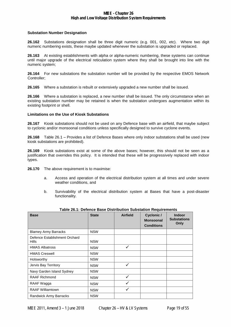
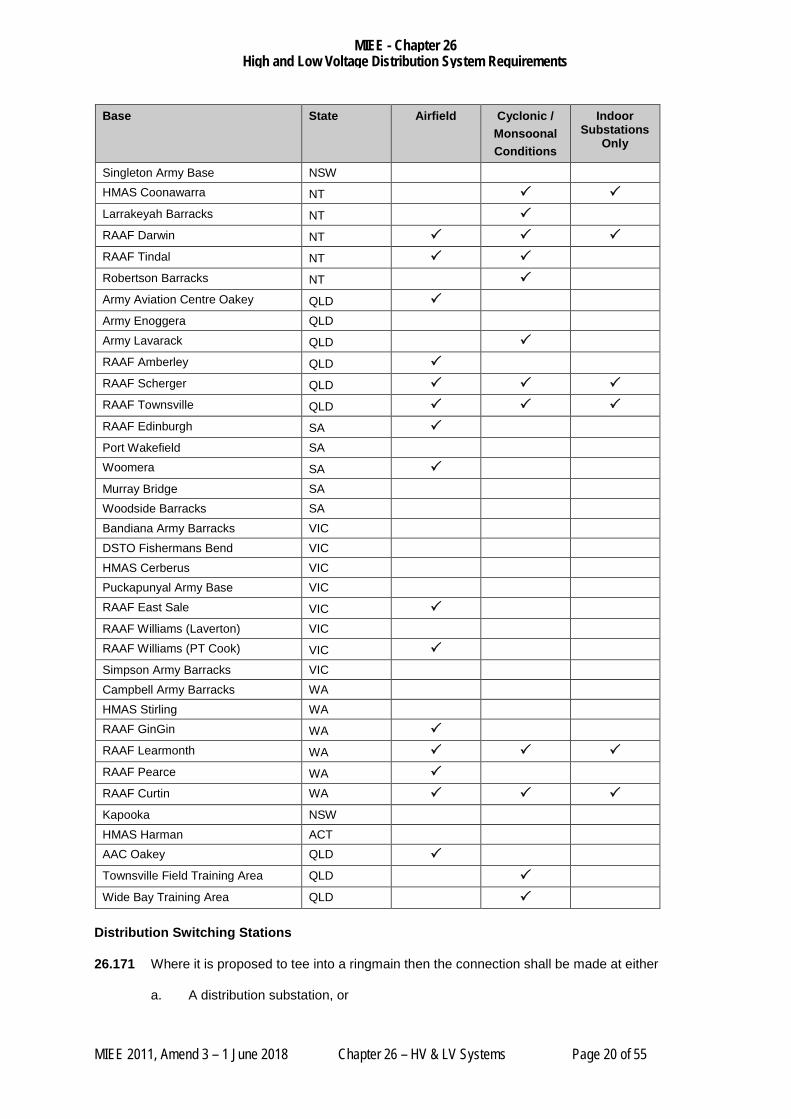
26.168 Table 26.1 – Provides a list of Defence Bases where only indoor substations shall be used (new kiosk substations are prohibited).
26.169 Kiosk substations exist at some of the above bases; however, this should not be seen as a justification that overrides this policy. It is intended that these will be progressively replaced with indoor types.
26.170 The above requirement is to maximise:
a. Access and operation of the electrical distribution system at all times and under severe weather conditions, and
b. Survivability of the electrical distribution system at Bases that have a post-disaster functionality.
Table 26.1: Defence Base Distribution Substation Requirements
Base State Airfield Cyclonic / Monsoonal Conditions
Indoor Substations
Only
Blamey Army Barracks NSW Defence Establishment Orchard Hills NSW
HMAS Albatross NSW
HMAS Creswell NSW Holsworthy NSW Jervis Bay Territory NSW
Navy Garden Island Sydney NSW RAAF Richmond NSW
RAAF Wagga NSW
RAAF Williamtown NSW
Randwick Army Barracks NSW
MIEE - Chapter 26 High and Low Voltage Distribution System Requirements
MIEE 2011, Amend 3 – 1 June 2018 Chapter 26 – HV & LV Systems Page 20 of 55
Base State Airfield Cyclonic / Monsoonal Conditions
Indoor Substations
Only
Singleton Army Base NSW HMAS Coonawarra NT Larrakeyah Barracks NT
RAAF Darwin NT RAAF Tindal NT
Robertson Barracks NT
Army Aviation Centre Oakey QLD
Army Enoggera QLD Army Lavarack QLD
RAAF Amberley QLD
RAAF Scherger QLD
RAAF Townsville QLD
RAAF Edinburgh SA
Port Wakefield SA Woomera SA
Murray Bridge SA Woodside Barracks SA Bandiana Army Barracks VIC DSTO Fishermans Bend VIC HMAS Cerberus VIC Puckapunyal Army Base VIC RAAF East Sale VIC
RAAF Williams (Laverton) VIC RAAF Williams (PT Cook) VIC
Simpson Army Barracks VIC Campbell Army Barracks WA HMAS Stirling WA RAAF GinGin WA
RAAF Learmonth WA
RAAF Pearce WA
RAAF Curtin WA
Kapooka NSW HMAS Harman ACT AAC Oakey QLD
Townsville Field Training Area QLD
Wide Bay Training Area QLD
Distribution Switching Stations
26.171 Where it is proposed to tee into a ringmain then the connection shall be made at either
a. A distribution substation, or
MIEE - Chapter 26 High and Low Voltage Distribution System Requirements
MIEE 2011, Amend 3 – 1 June 2018 Chapter 26 – HV & LV Systems Page 21 of 55
b. A distribution switching station.
26.172 Distribution switching stations can be used to optimise HV cabling where the closest distribution substation is some distance away.
26.173 The distribution switching station shall be housed within a suitable purpose-built building or kiosk arrangement. This shall be sized to suit the HV RMU and any ancillary equipment, and the associated maintenance clearances.
Outdoor Distribution Substations (open yard type or pole-mounted)
26.174 No new outdoor distribution substations (open yard type), or pole-mounted, are permitted on Defence sites.
26.175 Alterations and/or upgrading of outdoor equipment at existing outdoor distribution substations are not permitted.
26.176 Where the opportunity arises, the Defence preference is to replace any open yard type substations with substations in conformance with this policy.
Examples of appropriate arrangements are shown on the following figures.

MIEE - Chapter 26 High and Low Voltage Distribution System Requirements
MIEE 2011, Amend 3 – 1 June 2018 Chapter 26 – HV & LV Systems Page 22 of 55
Figure 26.1: Typical High Voltage Switchroom (ISS/PSS) General Arrangement
MIEE - Chapter 26 High and Low Voltage Distribution System Requirements
MIEE 2011, Amend 3 – 1 June 2018 Chapter 26 – HV & LV Systems Page 23 of 55
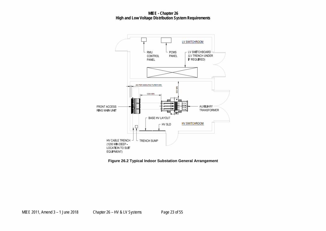
Figure 26.2 Typical Indoor Substation General Arrangement

MIEE - Chapter 26 High and Low Voltage Distribution System Requirements
MIEE 2011, Amend 3 – 1 June 2018 Chapter 26 – HV & LV Systems Page 24 of 55
ISS SUPPLY 2
CEPS.GEN 2
CEPS.BT2
CEPS.ISS
CEPS.BT1
CEPS.01 CEPS.GEN 1
ISS.BT1
ISS.06
ISS.CEPS
ISS SUPPLY 1
ISS.BT2
CEPS.T
09.0
4
09.T
1
09.0
2
09.T
2
SS 09
750kVA750kVA500kVA
08.T
04.IS
S
SS 04
04.0
9
1000 kVA
GEN 2
GEN 1
1000 kVA
CENTRAL EMERGENCY POWER STATION(CEPS) 11kV
200kVA
01.0
2
02.0
9
02.0
6
02.0
1
SWS 02
01.C
EPS
SWS 01
06.T
100kVA
06.0
3
06.0
2
SS 06
11kV INTERCONNECTOR
No. 2SUPPLY FEEDER
03.0
6
100kVA
SS 03
SUPPLY FEEDERNo. 1
INTAKE SWITCHING STATION(ISS) 11kV 06
.15
15.0
6
SS 15
15.T
15.1
6
100kVA100kVA
16.S
16.T
SS 16
16.1
5
SPARE
08.1
3TEE
14
50kVA
D3000
SS 13SS 14
D3001
50kVA
CEPSLOCAL SUPPLY
ISS.04 1 2
09.C
EPS
01.0
7
CEPS.09
03.IS
S
03.T
Figure 26.3: High Voltage Switchgear Labelling Diagram

MIEE - Chapter 26 High and Low Voltage Distribution System Requirements
MIEE 2011, Amend 3 – 1 June 2018 Chapter 26 – HV & LV Systems Page 25 of 55
KIOSK SUBSTATIONS
Permitted Kiosk Types
26.177 Essentially only two (2) types of the kiosk substations are permitted on Defence sites. These are:
a. Type A – That shown in the Standard Drawings below or
b. Type B – Those utilised by the NSP local to the Defence site.
26.178 Type A kiosk substations are required if a PCMS or other system exists on the site, or where the site has a load shedding system.
Type A Substations
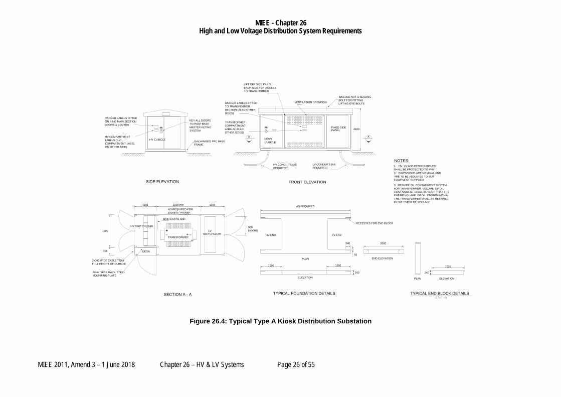
26.179 All Type A kiosk substations shall comply with the following performance requirements:
a. The kiosk shall have the capability to be able to accommodate the installation of a four circuit HV RMU consisting of three ring switches plus one transformer feeder;
b. Have adequate capacity for the installation of a 1.5 MVA transformer;
c. Maximum transformer capacity allowed for kiosk arrangement is 1.5 MVA.
d. Permit the installation of at least four LV outgoing feeds each with a capacity of 630A, CT metering and load shedding controls;
e. Segregated HV, Transformer, LV and DESN compartments;
f. The facility to remove/install the HV switchgear, Transformer or LV switchgear via the access doors/panels or via a removable roof;
g. A dust and water ingress protection level of IP 54 for all compartments (other than the transformer compartment) or the respective switchboards within the compartment;
h. A grading ring and earth system and
i. In all cases ease of access and maintenance to all equipment is the first consideration.
MIEE - Chapter 26 High and Low Voltage Distribution System Requirements
MIEE 2011, Amend 3 – 1 June 2018 Chapter 26 – HV & LV Systems Page 26 of 55
Figure 26.4: Typical Type A Kiosk Distribution Substation
TRANSFORMER LV
DESN
SIDE ELEVATION
HV CUBICLE
NOTES:
FRONT ELEVATION
HV SWITCHGEAR SWITCHGEAR
SECTION A - A
A 2100
1100 2200 min 1200
400
1600
FIXED SIDE PANEL
TYPICAL FOUNDATION DETAILS
PLAN
ELEVATION
END ELEVATION
PLAN ELEVATION
RECESSES FOR END BLOCK LV END HV END
TYPICAL END BLOCK DETAILS
240 50
240 1200 1100
AS REQUIRED
2000
1620 240
LIFT OFF SIDE PANEL EACH SIDE FOR ACCESS TO TRANSFORMER
VENTILATION OPENINGS WELDED NUT & SEALING BOLT FOR FITTING LIFTING EYE-BOLTS DANGER LABELS FITTED
TO TRANSFORMER SECTION (ALSO OTHER SIDES) TRANSFORMER COMPARTMENT LABELS (ALSO OTHER SIDES)
KEY ALL DOORS TO RAAF BASE MASTER KEYING SYSTEM
GALVANISED PFC BASE FRAME
DANGER LABELS FITTED ON RING MAIN SECTION DOORS & COVERS HV COMPARTMENT LABELS (L.V. COMPARTMENT LABEL ON OTHER SIDE)
HV CONDUITS (AS REQUIRED) LV CONDUITS (AS
REQUIRED)
AS REQUIRED FOR 1000kVA TRANSF.
2x300 WIDE CABLE TRAY FULL HEIGHT OF CUBICLE 3mm THICK GALV. STEEL MOUNTING PLATE
MAIN EARTH BAR
2. DIMENSIONS ARE NOMINAL AND ARE TO BE ADJUSTED TO SUIT EQUIPMENT SUPPLIED. 3. PROVIDE OIL CONTAINMENT SYSTEM FOR TRANSFORMER. VOLUME OF OIL CONTAINMENT SHALL BE SUCH THAT THE ENTIRE VOLUME OF OIL STORED WITHIN THE TRANSFORMER SHALL BE RETAINED IN THE EVENT OF SPILLAGE.
1. HV, LV AND DESN CUBICLES SHALL BE PROTECTED TO IP54.
900 DOORS
A DESN CUBICLE
MIEE - Chapter 26 High and Low Voltage Distribution System Requirements
MIEE 2011, Amend 3 – 1 June 2018 Chapter 26 – HV & LV Systems Page 27 of 55
Enclosure Requirements
26.180 Each kiosk substation enclosure shall be manufactured of minimum 3mm mild steel or 304 grade stainless steel, or equivalent strength marine grade aluminium with a hot dip galvanised steel Parallel Flange Channel (PFC) base-frame.
26.181 Preference shall be given to kiosk substation arrangements which offer the lowest through life costs when considering the need for painted structures.
26.182 Access doors that open to 180° shall be provided for access to the HV and LV equipment.
26.183 Access to the transformer compartment may be gained via bolt-on panels.
26.184 All penetrations from one compartment to the other shall be via glands.
Access and Clearances
26.185 Generally the location of the kiosk substation shall provide personnel access to all sides. Care must be taken to ensure any access doors/panels may be opened and not restrict free-access past the door/panel.
26.186 The kiosk substation shall be sited such that the network operator shall at times have an unimpeded access to operate any equipment and to be able to escape in the event of any fault.
26.187 The minimum clearances around kiosk substations shall be in accordance with AS 2067.
Foundations
26.188 The kiosk substation shall be located upon a concrete footing so that it is above the surrounding ground. Under normal circumstances the above-ground layout should generally comply with the details shown in the Standard Drawing – Figure 26.4.
NOTE: The foundation drawing is indicative only and the actual foundation utilised shall be designed to suit the requirements of the installation including any allowance for the geotechnical conditions.
26.189 The foundation and any other structure under the kiosk shall prevent pooling or retention of water under the kiosk or around cables.
Substation Lighting and Power
26.190 Kiosk substations shall have a;
a. Door switch activated lights for each cubicle;
b. General purpose GPO in the LV compartment;
c. GPO in the Defence Engineering Service Network (DESN) compartment
26.191 The GPO’s, lights and light switches shall be readily accessible without exposure to any live parts or equipment.
Heat Gain
26.192 The kiosk substation and its equipment shall be designed and constructed to be suitable to operate within the temperature ranges that it will experience at the site in question.
MIEE - Chapter 26 High and Low Voltage Distribution System Requirements
MIEE 2011, Amend 3 – 1 June 2018 Chapter 26 – HV & LV Systems Page 28 of 55
26.193 Due consideration shall be given to the impact of solar radiation and the heat from the transformer on the internal operating temperatures of the kiosk substation.
Bases Subject to Cyclonic and Monsoonal Conditions
26.194 Subject to the Limitations on the use of Kiosk Substations described above, where kiosk substations are to be used within Bases subject to cyclonic conditions, the substation shall have been designed, constructed and rated to be able to withstand the applicable cyclonic conditions, including any flying debris.
INDOOR SUBSTATIONS
General
26.195 The term indoor substation used throughout this policy shall be taken to apply to all Indoor or chamber structures where the BCA shall apply to the construction of the building to house any high and low voltage distribution installation. This shall incorporate;
a. Indoor Substations (both Distribution and Primary) and
b. Indoor Switching stations (both Distribution and Primary)
26.196 All new HV indoor substations shall allow for operations and maintenance indoors in all normally encountered weather conditions.
Building Arrangement
26.197 Indoor distribution substations can be either part of the structural envelope of the main building / facility or a free standing structure.
26.198 Indoor primary substations shall be free-standing structures.
26.199 Distribution substations shall have separate rooms as follows:
a. The HV room of the substation shall house the HV Ring Main Unit (RMU) and transformer.
b. The LV room shall house the substation LV switchboard, LV Systems (such as LEG controls, where required), and provision for the Defence Engineering Services Network (DESN).
26.200 Intake and Primary Substations shall have separate rooms as follows:
a. Transformer Room or Yard housing the substation power transformer and where appropriate the station auxiliary transformer;
b. HV Switchroom/s housing the HV switchboard/s.
c. A separate battery room housing the batteries for the auxiliary DC power supplies, if required under Clause 26.363;
d. Control Room housing the Control panels,
e. Auxiliary supplies, communications racks, any other LV systems and provision for the Defence Engineering Services Network (DESN).
26.201 Each room, with the exception of the battery room is required to have independent access from the outside of the building suitable for the installation and removal of the equipment therein.
MIEE - Chapter 26 High and Low Voltage Distribution System Requirements
MIEE 2011, Amend 3 – 1 June 2018 Chapter 26 – HV & LV Systems Page 29 of 55
26.202 It shall not be necessary to pass through any room containing HV equipment in order to access other rooms.
26.203 Rooms containing HV equipment shall generally have two independent egress paths. It is permissible for one of these paths to be through the LV room or Control Room.
26.204 Access to rooms containing HV equipment is restricted and shall require the use of a ‘HV’ key. As a result egress paths from other rooms cannot pass through rooms where HV equipment is installed.
26.205 Where an indoor substation is constructed as part of another facility, it shall not be possible to gain access to the attached facility from the substation.
26.206 An attached substation shall have at least one frontage in an external wall of the building. Preference shall be given to locating the substation in an outer corner of a building so as to provide two (2) frontages.
26.207 Personnel access must be available at all times and shall be located where they cannot be obstructed by any means which includes vehicles, equipment or other impediments.
Equipment Provision
26.208 Provision shall be made when allocating space for distribution transformer for future upgrades of the transformer to a rating of at least 1.5 MVA.
26.209 In cases where the overall distribution substation capacity is larger than 1.5MVA, due consideration shall be given to provide multiple transformers of equal size.
Equipment Access
26.210 External access for installation and removal of equipment shall be considered in the design. It shall be possible to place the equipment onto a suitable flat area or hardstand immediately outside the access door and to allow for wheeling or skating of the equipment into position from that location.
26.211 Internal access for the equipment within the building shall be considered in the design. It is undesirable if large equipment is required to be moved over floor trenches or pits, and this shall be avoided.
26.212 Equipment access can be provided by suitable double sized door or by demountable louver panels. Particular attention shall be given to adequate height of the openings as some equipment can be quite high.
26.213 Equipment access shall be arranged such that equipment removal or insertion can be performed without impacting on other major items of equipment.
Cable Access
26.214 HV cables shall generally be installed within cable trenches in:
a. HV rooms of distribution substations, and
b. HV switchrooms of primary substations
26.215 LV transformer tails can be either overhead or in-trench.
26.216 Overhead cable runs shall maintain suitable minimum clearance of 2700mm Above Finished Floor Level, AFFL, for personnel and equipment access.
26.217 The LV trench shall be separate to the HV trench.

MIEE - Chapter 26 High and Low Voltage Distribution System Requirements
MIEE 2011, Amend 3 – 1 June 2018 Chapter 26 – HV & LV Systems Page 30 of 55
26.218 Cable trenches shall be:
a. Provided with pulling eyes to facilitate the installation of cables. The number and location of haulage eyes shall suit the duct banks installed, and
b. Graded to a sump to allow a portable or fixed pump to be used to remove water. This sump shall be located in an accessible position in a location clear of cable entries or other areas that might be obstructed by cables.
c. Minimum of 1200mm deep and of adequate depth for the minimum-bending radius of the cable plus 20%.
d. Open cable trenches shall be covered with removable covers of a mass not exceeding 15kg each. The top edge of the cable trench shall be rebated so that the covers are installed flush with the adjacent floor level.
e. Trench entries shall be sealed to prevent the entry of water and to contain any oil spill.
f. Conduit entries into cable trenches shall be fitted with bellmouths to minimise the risk of damage to the cable during installation.
Internal Clearance Requirements
26.219 The minimal internal clearance for equipment shall be as required by Table 26.2 below.
Table 26.2: Indoor Substation Minimum Clearances
Distance Description
0.9m Horizontally between any item of free-standing equipment and the substation wall
0.6m Horizontally between any two (2) items of equipment 1.2m Horizontally in front of any HV switchgear with any doors open. As Recommended by the Manufacturer
Horizontal distance between the rear of front access only HV switchgear and the substation wall
Fire Protection Systems
26.220 Fire protection shall be provided as required by and in fully conformance with the requirements of AS 2067, the Manual of Fire Protection Engineering (MFPE) and the National Construction Code - Building Code of Australia (BCA). This includes the provision of:
a. Signs;
b. Extinguishers;
c. Detectors (if required), and
d. Fire suppression systems (if required).
Building Requirements
26.221 Substation construction shall conform to the requirements of AS 2067, including the requirements for fire rating and consideration given to the effects of blast.
MIEE - Chapter 26 High and Low Voltage Distribution System Requirements
MIEE 2011, Amend 3 – 1 June 2018 Chapter 26 – HV & LV Systems Page 31 of 55
26.222 The preferred construction of substation internal and external walls is of either;
a. Hollow, core filled blocks with a minimum thickness of 190mm,
b. Cavity or solid brickwork with a minimum thickness of 230mm,
c. In-situ reinforced concrete or
d. Pre-cast reinforced concrete.
26.223 The floor shall be fully designed to withstand the loadings of the equipment to be installed.
26.224 The uniformity of the floor shall comply with the requirements as designated by the manufacturer of the switchgear.
26.225 The ceiling height shall be adequate for the equipment, including any requirements related to arc venting. The minimum ceiling height shall be 3m at all locations.
26.226 In cyclonic areas the ceiling of switchrooms and control rooms in Primary Substations shall consist of reinforced concrete.
26.227 A waterproof membrane shall be provided around all walls and/or floors in constant contact with soil.
26.228 All walls built below the finished surface level of the ground shall have a drained cavity included along the full length of the wall/s.
26.229 All penetrations in the walls shall be sealed to prevent the ingress of water.
26.230 If the finished surface level of the substation floor is below the water table or where the water table may rise above the finished surface level, provide gravity drainage to a suitable discharge point or sump.
26.231 The internal wall surfaces of the substation shall be coated with an acrylic based sealer and at least two (2) coats of cream low sheen acrylic based paint.
26.232 All un-galvanised metal surfaces shall be coated with a zinc rich paint e.g. “Killrust grey”.
26.233 Concrete floors shall be sealed using an epoxy finish.
Acoustic and Other Emissions
26.234 Substations can be the source of acoustic, EMI and other emissions that can affect neighbouring facilities and people. The substation design and equipment selection shall minimise the effects on adjacent sensitive facilities, people and processes.
26.235 Transformers shall have adequate sound isolation from the other rooms of a substation so that verbal communication in those rooms, particularly radio / phone communication, are not affected.
Ventilation and Air Conditioning
26.236 HV switchrooms and control rooms at Primary substations shall be ventilated and air conditioned to minimise thermal stress on the equipment, prevent condensation and prevent the entry of dust.
MIEE - Chapter 26 High and Low Voltage Distribution System Requirements
MIEE 2011, Amend 3 – 1 June 2018 Chapter 26 – HV & LV Systems Page 32 of 55
26.237 Where practical all other distribution and primary substation equipment shall be installed within spaces with natural ventilation.
26.238 All ventilation openings shall be made using weatherproof and vermin proof vents or louvers. These shall minimise the ingress of dust and other contamination.
26.239 Due consideration and control measures shall be put in place to ensure that the risk of condensation forming within the structure is minimised.
Substation Lighting and Power
26.240 Provide general lighting with battery backed operation lighting (2 hour minimum) in the HV room, LV Switchroom, Control Room and the LEG room, to allow operations to be performed during power outages.
26.241 Provide power outlets in each substation room as convenience outlets for maintenance purposes.
a. These power outlets shall be supplied from the substation services section of the LV Switchboard.
Operational Drawings
26.242 In each room containing a HV switchboard or RMU the following drawings shall be provided:
a. A site HV single line diagram, and
b. A site geographic layout showing the location of all substations and the route of HV cables.
26.243 The drawings shall be wall mounted within clear-fronted, heavy-duty frame.
26.244 The drawings shall be to a size that allows easy reading, typically A1 size for a medium size base.
Bases Subject to Cyclonic and Monsoonal Conditions
26.245 Indoor substation structures intended for use at Bases subjected to cyclonic conditions shall be fully cyclone rated. See Table 26.1 for a list of bases subject to cyclonic conditions.
26.246 The location and Ingress Protection (IP) rating of the equipment should consider that large quantities of water could enter the substation during a cyclone and that the substation is required to remain operational at all times.
26.247 The substation shall be able to be safely operated at all times.
Earth Covered Substations (Passive Defence Measures)
26.248 Some electrical infrastructure will need to be protected from certain events such as the need for earth covered substations.
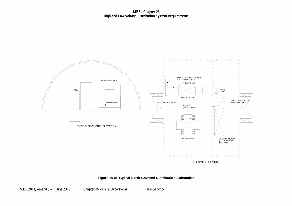
26.249 The actual substation construction and all special requirements such as the required hardening will be identified by Defence in the project brief or other suitable means. This may require specialist engineering skills to design the passive defence requirements. A typical substation layout is shown at figure 26.6, other considerations include:
a. Siting of substations and infrastructure within secure zones (eg away base perimeter fence);
MIEE - Chapter 26 High and Low Voltage Distribution System Requirements
MIEE 2011, Amend 3 – 1 June 2018 Chapter 26 – HV & LV Systems Page 33 of 55
b. Consideration of the impact vibration throughout the facility; and
c. The spacing limitations within the substation such as those with arch type structures needs to be addressed when determining the equipment layout;.
MIEE - Chapter 26 High and Low Voltage Distribution System Requirements
MIEE 2011, Amend 3 – 1 June 2018 Chapter 26 – HV & LV Systems Page 34 of 55
Figure 26.5: Typical Earth-Covered Distribution Substation
EQUIPMENT LAYOUT
TYPICAL SECTIONAL ELEVATION
SINGLE LINE DIAGRAM AND GEOGRAPHIC LAYOUT
TRANSFORMER
TRANSFORMER
LV SWITCHBOARD (LV TRENCH UNDER IF REQUIRED)
RING MAIN UNIT
DESN PANEL RMU
TRENCH (WITH COVERS)
HV EARTH BAR LV SWITCHBOARD
FULL LOUVRE DOORS SOLID DOORS (WITH SMALL LOUVRES)
MIEE - Chapter 26 High and Low Voltage Distribution System Requirements
MIEE 2011, Amend 3 – 1 June 2018 Chapter 26 – HV & LV Systems Page 35 of 55
HIGH VOLTAGE SWITCHGEAR
General
26.250 Two types of HV Switchgear generally exist in Defence establishments:
a. Switchboards and Switchyards – These are used at major switching nodes of the distribution network, such as intake and primary substations and switching stations.
b. Ring Main Units – These consist of switchgear within the secondary distribution system. They are generally used to control the distribution transformer at distribution substations.
26.251 All HV switchboards shall be located indoors within switchrooms. The use of outdoor switchyards shall only be considered, when agreed by DEEP, when there is a significant cost saving in terms of whole of life cost, and where there is no impact in terms of safety or capability.
26.252 In order to simplify operations and maintenance, high voltage switchgear should be standardised at each Defence establishment. As such the switchgear must be specified by make and model to match the existing switchgear at the establishment, noting that the Designer must consider the suitability of maintaining the existing switchgear standards as part of the design considerations. In particular the designer should consider the safety and ongoing supportability of the equipment.
26.253 In establishing the switchgear that is the standard switchgear for the Base the designer shall consult with the Defence Electrical Operating Authority.
26.254 If, subject to Clause 26.252, it is proposed to move away from an established standard switchgear the new switchgear shall be:
a. In accordance with the requirements of this Policy,
b. Its selection shall be undertaken in consultation with the Defence Electrical Operating Authority and Defence Network Operator for that Defence electrical reticulation system,
c. An adequate number of spares are specified and provided, as agreed to by the Base Manager and Defence Electrical Operating Authority and Defence Network Operator.
26.255 The Designer shall consult the Defence Electrical Operating Authority for the spares that are required to be retained on site to support the ongoing capability and operations. The design shall give due consideration to the holding of adequate spares.
HIGH VOLTAGE SWITCHBOARDS AND SWITCHYARDS
HV Switchboards
26.256 All switchboards and equipment shall be metal enclosed dead front type so as to increase operator safety.
26.257 All exposed metalwork shall be bonded to earth via appropriate methods in accordance with AS 2067 and it shall not be possible to access or come in contact with live conductors without removing guards or other barriers.

MIEE - Chapter 26 High and Low Voltage Distribution System Requirements
MIEE 2011, Amend 3 – 1 June 2018 Chapter 26 – HV & LV Systems Page 36 of 55
26.258 The switchboard panels shall consist of freestanding, dead-front, metal-clad, panel types equipped with SF6 or vacuum switchgear with the protection relays powered from auxiliary DC supplies. The protection relays are generally to be supplied as a panel and form part of the switchboard or they are to be housed in separate protection racks.
26.259 The switchgear shall be capable of delivering continuous full rated load for the site and be fitted with fault-make earth switches.
26.260 The switchboard shall be constructed with separate electrically isolated compartments so that a fault in one compartment does not result in damage in the other compartments, as follows:
a. Cable Termination Compartment: Space for termination of HV cables, CTs, VTs and separate earthing switch.
b. Circuit Breaker Compartment: Space for the withdrawable circuit breaker truck, where applicable.
c. Busbar Compartment: Space for the interconnecting HV busbar assembly and Bus VTs.
d. LV Compartment: Space for electrical controls, metering and protection.
26.261 Mechanical indicators shall provide visual indication of switch status at all times.
26.262 HV surge arrestors shall be fitted to panels that are designated for:
a. Incoming Feeders; and
b. Generators connected at high voltage.
Capability Requirements
26.263 The arrangement of the switchgear shall be determined by the Designer based upon the capability requirements for the Base. The selection of switchgear and switchboard shall consider:
a. The reduction in Base capability that will result from an outage of the switchgear and minimising an outage during its repair;
b. The consequence of this reduction in capability, including the consequences of any reduction in power system redundancy that will result from a single event; and
c. The time required to return the switchgear and switchboards back to service.
26.264 The three main switchgear arrangements to be considered are:
a. Withdrawable: Where the circuit breaker can be removed from the switchgear panel by withdrawing the truck with the busbar live;
b. Demountable: Where the circuit breaker is designed to be removed from the panel using tools without significant work, but with the switchboard or part de-energised; and
c. Fixed: Where the circuit breaker can only be removed from the panel with significant work, with the switchboard de-energised.

MIEE - Chapter 26 High and Low Voltage Distribution System Requirements
MIEE 2011, Amend 3 – 1 June 2018 Chapter 26 – HV & LV Systems Page 37 of 55
26.265 The skills available at the location can have a significant impact on the time and cost of returning the switchgear to service. The arrangement of the switchgear should consider the skills available locally to support the switchgear.
26.266 On existing Bases the existing switchgear should be used as a guide to determine the preferred arrangement.
26.267 Non-withdrawable switchgear shall be double-break; with a separate isolator in series with the circuit breaker.
HV Switchyards
26.268 HV switchyards shall comply with the requirements of AS 2067.
26.269 The open ground of the switchyard shall be covered with a layer of gravel with a minimum thickness of 200mm.
26.270 The fencing around the switchyard shall consist of anti-climbing palisades.
26.271 Transient Over-voltage Protection is to provide protection or otherwise ensure correct operation of the installation and equipment where voltage excursions are anticipated outside the permissible range. This shall include:
a. Over voltage protection on incoming feeders, and
b. Over voltage and under voltage protection immediately after any automatic on-load tap changers.
26.272 Where equipment is susceptible to voltage transients suitable protection is to be provided; ie
a. Surge protection for switching and other similar transient over-voltages; and
b. Lightning protection.
Operational and Maintenance Control
26.273 Normal operational control of switchgear shall be from a mimic panel outside the switchroom or switchyards. The mimic panel shall generally be located in an adjacent Control Room.
26.274 The mimic panel shall display the status of the circuits together with major parameters, such as bus voltage and load currents.
26.275 Control shall only be possible from the mimic panel once a HV access key is inserted into a keyswitch on the panel. Indication at the mimic shall always be active.
26.276 Where the switchboard is automatically controlled from another system (eg GCS), or from another location, the HV access key shall also disable that control and enable exclusive control from the mimic.
26.277 A circuit shall not be controllable from the mimic unless the CB is in Remote Mode, CB truck in the Service position and racked-in, and the circuit does not have a fault. In this event a suitable indicator shall be provided on the mimic to indicate that the circuit is Locked.
26.278 For emergency and maintenance purposes the following controls and indictors shall be provided on each switchgear panel:
MIEE - Chapter 26 High and Low Voltage Distribution System Requirements
MIEE 2011, Amend 3 – 1 June 2018 Chapter 26 – HV & LV Systems Page 38 of 55
a. Local Open/Close electrical controls.
b. Local/Remote switch – the Open pushbutton shall be active irrespective of the position of the Local/Remote switch.
c. Illuminated indicators for:
(1) Open (or not racked in) – Green (The Open indicator shall light even if the CB truck is not in the panel.)
(2) Closed (In the Service position and racked in) - Red
(3) Tripped (due to the action of any protection relay) - Yellow
(4) CB in Local Mode - Yellow
26.279 Switches shall be 22 mm diameter oil tight mechanisms.
26.280 Indicators shall be 22 mm diameter oil tight mechanisms with multi-chip LED lamps.
Remote Control and Monitoring
26.281 Where switchgear is monitored remotely by another system (e.g. GCS or PCMS) provide the following additional indication to these remote systems:
a. Status of the Auto/Manual switch on the mimic panel;
b. Status of HV access keyswitch;
c. Status signals to indicate:
(1) Open (or not racked-in);
(2) Closed (In the Service position and racked-in);
(3) Tripped (due to the action of any protection relay);
(4) CB in Local Mode
(5) CB truck status (CB truck not in the Service position and racked-in);
(6) The watchdog timer of each protection relay (to PCMS only);
(7) The communications fault of each current differential protection relay (to PCMS only);
(8) Trip circuit supervision and other fault outputs of each panel (to PCMS only); and
(9) Fault outputs of any communications equipment (to PCMS only)
26.282 Where switchgear is controlled by another system (e.g. GCS) provide the inputs or control features at each panel from each remote system:
a. Open
b. Close

MIEE - Chapter 26 High and Low Voltage Distribution System Requirements
MIEE 2011, Amend 3 – 1 June 2018 Chapter 26 – HV & LV Systems Page 39 of 55
26.283 Where a Substation Automation System (SAS) is implemented using protocols such as IEC 61850, the above status and control signals are to be transferred by high-level interface to the other systems provided this does not allow these other systems direct access to the substation data bus.
PROTECTION RELAYS – HV SWITCHBOARDS
General Requirements
26.284 The relays shall be mounted in such a way that all indicators are visible and all operations can be carried out without opening any compartment doors.
26.285 All microprocessor based protection relays shall be of the monitored type, using a watchdog timer that is independent of the processor.
26.286 Protective relays must have suitable setting ranges to meet the system requirements.
26.287 Programmable Controllers will not be accepted as an alternative to protection relays or control equipment.
Protection Requirements
26.288 The Designer shall provide a Protection Report detailing the protection settings and how these will grade with other protection for all new works or where changes are made to the high voltage network that may affect the protection system. Defence distribution networks must grade with the NSP protection.
26.289 In addition to what the NER and NSP may have as to their protection requirements the following minimum protection requirements will apply to Defence;
26.290 Incoming Feeders shall have:
a. Feeder Overcurrent;
b. Feeder Earth Fault;
c. Directional OC/EF, where required;
d. Over voltage (typically set to +12%);
e. Reverse Feed – where this is not provided by the NSP
26.291 HV Buses for Operational Bases and critical and complex installations shall have high impedance differential or other zonal scheme, on each bus section.
26.292 Interconnectors (cables that directly connect switchboards at primary substations or switching stations) shall have:
a. Current differential protection; and
b. Backup IDMT for overload protection.
26.293 Generators >800kW and those that connect at 11kV shall have:
a. Complete Alternator Protection; with the following minimum elements;
(1) Generator biased differential;

MIEE - Chapter 26 High and Low Voltage Distribution System Requirements
MIEE 2011, Amend 3 – 1 June 2018 Chapter 26 – HV & LV Systems Page 40 of 55
(2) Overcurrent;
(3) Earth fault;
(4) Voltage dependent overcurrent;
(5) Over voltage;
(6) Under voltage;
(7) Loss of excitation;
(8) Under excitation;
(9) Reverse power; and
(10) Neutral displacement.
26.294 Power Factor Correction Capacitors shall have protection for:
a. Overcurrent;
b. Earth Fault; and
c. Out of Balance.
Operational Requirements
26.295 The operation of any protection element shall be individually indicated to the generator control system and the PCMS.
26.296 Synchronism check relays shall be provided on all switchboard panels where:
a. There is a possibility (however remote) that the supplies on each side might not be synchronised, or
b. To prevent automatic systems mal-operating, such as where:
(1) The HV system is energised by on-Base standby generators; and
(2) The circuit is subject to automated control or remote manual control.
26.297 The protection systems should allow cables to run with a nominal overload for short periods of time under emergency conditions (Emergency Rating), however this situation should not be allowed for extended periods. This will require suitable selection of time multipliers when developing the protection scheme.
RING MAIN UNITS (RMUS)
General Requirements
26.298 The RMUs supplied shall consist of freestanding, dead front, metal clad, panel types equipped with SF6 or vacuum switchgear and protection relays as a single assembly.
26.299 The switchgear shall be capable of delivering continuous full rated load to the site and be fitted with fault-make earth switches.
26.300 Unless otherwise stated, RMUs shall have the following characteristics:
MIEE - Chapter 26 High and Low Voltage Distribution System Requirements
MIEE 2011, Amend 3 – 1 June 2018 Chapter 26 – HV & LV Systems Page 41 of 55
a. Mechanical indicators shall provide visual indication of switch status at all times;
b. Provision shall be made for locking of the RMU in the ‘OFF’ and ‘Earthed’ positions;
c. Provide auxiliary switches that indicate the Open/Closed/Tripped status of each item of switchgear. Connect these switches to a separate terminal strip for extension to the PCMS;
d. Provide one set of equipment required for the safe and satisfactory operation of the switchgear, such as operating handles, fuse extractors, etc. for each RMU. Mount equipment within a mounting frame suitable for wall mounting in a substation building or fixing within a kiosk substation;
e. Provide capacitive test points for voltage indication and phasing purposes; and
f. Where viable and practical to do so, the RMU should be operated without the need to be standing directly in front of it / clear of any potential blast from a switchgear fault. Preference is for operation of the RMU from a control panel at the LV end of the substation or from the LV switchroom. Operation of the control panel shall require the insertion of a HV key.
26.301 Protection shall consist of circuit breakers complete with self-powered protection relays. Protection relays shall have as a minimum:
a. IEC – Standard Inverse;
b. IEC – Very Inverse;
c. IEC – Extremely Inverse; and
d. Definite Time
e. Separate curves for both phase and earth fault protection.
HV POWER FACTOR CORRECTION (PFC)
26.302 Power factor correction capacitors, when required, shall be fitted with integral resistors to discharge the bank after the supply is removed.
26.303 Safety interlocks shall be proved to ensure:
a. The earth switch cannot be closed until a time period after the CB is opened;
b. The capacitors or any HV associated with the PFC bank cannot be accessed until the earth switch is closed, and
c. The CB cannot be reclosed for a time period after the CB is opened.
26.304 The time period shall be at least twice that which is necessary to discharge a fully charged PFC bank to a safe level.
26.305 Ensure that the power factor correction does not interfere with any ripple protection or control system on or across the NSP’s network.
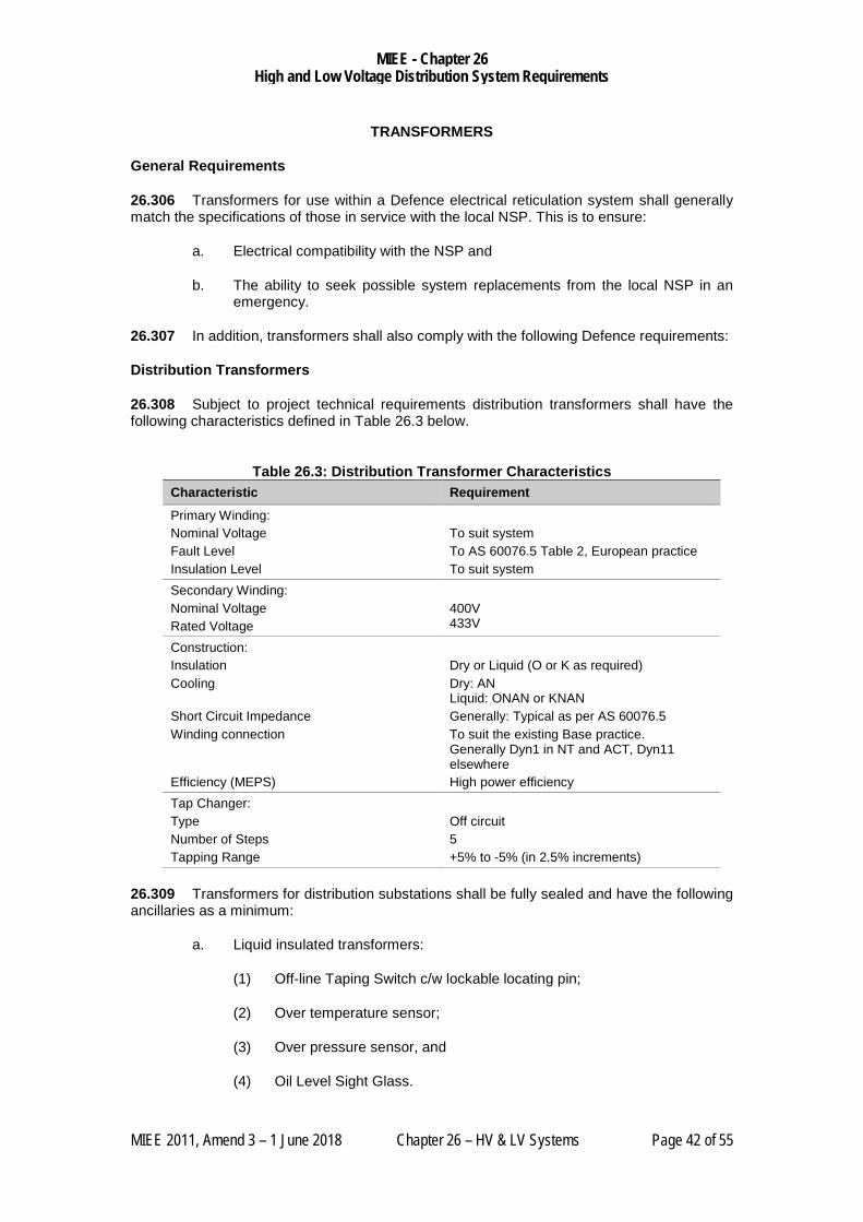
MIEE - Chapter 26 High and Low Voltage Distribution System Requirements
MIEE 2011, Amend 3 – 1 June 2018 Chapter 26 – HV & LV Systems Page 42 of 55
TRANSFORMERS
General Requirements
26.306 Transformers for use within a Defence electrical reticulation system shall generally match the specifications of those in service with the local NSP. This is to ensure:
a. Electrical compatibility with the NSP and
b. The ability to seek possible system replacements from the local NSP in an emergency.
26.307 In addition, transformers shall also comply with the following Defence requirements:
Distribution Transformers
26.308 Subject to project technical requirements distribution transformers shall have the following characteristics defined in Table 26.3 below.
Table 26.3: Distribution Transformer Characteristics
Characteristic Requirement
Primary Winding: Nominal Voltage Fault Level Insulation Level
To suit system To AS 60076.5 Table 2, European practice To suit system
Secondary Winding: Nominal Voltage Rated Voltage
400V 433V
Construction: Insulation Cooling Short Circuit Impedance Winding connection Efficiency (MEPS)
Dry or Liquid (O or K as required) Dry: AN Liquid: ONAN or KNAN Generally: Typical as per AS 60076.5 To suit the existing Base practice. Generally Dyn1 in NT and ACT, Dyn11 elsewhere High power efficiency
Tap Changer: Type Number of Steps Tapping Range
Off circuit 5 +5% to -5% (in 2.5% increments)
26.309 Transformers for distribution substations shall be fully sealed and have the following ancillaries as a minimum:
a. Liquid insulated transformers:
(1) Off-line Taping Switch c/w lockable locating pin;
(2) Over temperature sensor;
(3) Over pressure sensor, and
(4) Oil Level Sight Glass.

MIEE - Chapter 26 High and Low Voltage Distribution System Requirements
MIEE 2011, Amend 3 – 1 June 2018 Chapter 26 – HV & LV Systems Page 43 of 55
b. Dry type transformers:
(1) Off-line Taping links;
(2) Over temperature sensor;
Power Transformers
26.310 Power transformers for use in other than distribution substations (e.g. 33/11kV ISS transformers) shall have features and characteristics suited to the application and match as a minimum the local NSP specifications.
Table 26. 3: Power Transformer Characteristics
Characteristic Requirement
Primary Winding: Nominal Voltage Fault Level Insulation Level
To suit system To AS 60076.5 Table 2, European practice To suit system
Secondary Winding: Nominal Voltage Fault Level Insulation Level
To suit system To AS 60076.5 Table 2, European practice To suit system
Construction: Insulation Cooling Short Circuit Impedance Winding connection Efficiency (MEPS)
Liquid (O or K as required) Liquid: ONAN or KNAN Generally: Typical as per AS 60076.5 To suit the existing Base practice or NSP requirements. High power efficiency
Tap Changer: Type Number of Steps Tapping Range
On Load To suit system or to NSP requirements To suit system or to NSP requirements
26.311 Power transformers shall generally be vented with a conservator and have the following ancillaries as a minimum:
a. Winding Temperature Indicator
b. Oil Temperature Indicator
c. Tank Oil Level Indicator
d. Tank Buchholz
e. OLTC Buchholz
f. Oil Level Sight Glass.
Transformer Sizing
26.312 The transformer shall be suitably sized to supply the maximum demand of the planned loads with an allowance of at least 25% spare capacity.
MIEE - Chapter 26 High and Low Voltage Distribution System Requirements
MIEE 2011, Amend 3 – 1 June 2018 Chapter 26 – HV & LV Systems Page 44 of 55
26.313 Liquid insulated transformer shall have the capability (above the spare capacity) to deliver power at 20% overload for a period of two (2) hours in each twenty-four (24) hour period.
Transformer Protection - Distribution Transformer
26.314 Distribution transformers shall be protected against faults within the transformer or in the HV/LV tails with the following protection methods:
a. Transformer overload or overload of the HV/LV tails shall be provided by the LV circuit breakers;
b. Transformer internal faults or faults on the HV/LV tail shall be provided by the HV protection;
c. Transformer internal faults shall also be sensed using:
(1) An over pressure switch (on sealed transformers only); and
(2) An over temperature switch,
26.315 All protection shall coordinate fully with all upstream and downstream protection schemes.
Transformer Protection - Power Transformers
26.316 For transformers other than those for use as distribution transformers, the following protection shall be provided as a minimum:
a. Over-temperature;
b. Overcurrent;
c. Earth fault;
d. An overpressure switch (on sealed transformers only)
e. Buchholz; and
f. OLTC failure (if OLTC fitted).
26.317 Note that where transformers are part of a transformer-ended feeder extra consideration shall be made for the protection offered including the use of inter-tripping.
Acoustic Requirements
26.318 Under normal circumstances, Standard Limit transformers shall be utilised. However, under some circumstances where a substation is positioned adjacent a sensitive facility, Reduced Limit transformers can be utilised.

MIEE - Chapter 26 High and Low Voltage Distribution System Requirements
MIEE 2011, Amend 3 – 1 June 2018 Chapter 26 – HV & LV Systems Page 45 of 55
SUBSTATION LV SWITCHBOARDS
General Requirements
26.319 Substation low voltage switchboards shall be dead-front metal-clad with a minimum Form of:
a. Indoor Substations: Form 3b.
b. Kiosk Substations: Form 3b.
26.320 In the case of large facilities, where the substation forms part of the building and is basically dedicated, the substation LV Switchboard may be deleted and the LV tails from the transformer run directly to the building’s Main Switch Board, MSB.
26.321 Consideration can be given to higher forms of segregation for major, important or critical facilities.
26.322 Flexibility of supply shall remain a high priority at all times.
Switchboard and Equipment Sizing
26.323 Where two (2) transformers or more are used to supply large facilities, consideration of the following is required:
a. Parallel Operation – Transformers are not to be permanently paralleled.
(1) It is preferred that the transformers are operated independently as two supplies; and
(2) Notwithstanding the above, they shall be capable of operating in parallel in order to provide future flexibility and during switching operations.
b. Transformer sizing for important facilities shall be suitable to allow operations of critical / essential activities on failure of one transformer. Load limiting under these arrangements would be manually initiated at the main switchboard.
Transient Overvoltage Protection
26.324 Appropriate surge protection shall be provided for the LV distribution system.
26.325 Surge arresters shall consist of devices specifically designed for multi-pulse lightning events on powerlines installed in the accordance with the requirements of AS 4070.
26.326 The arresters shall be segregated from other switchboard components by solid metal barriers.
26.327 Surge arrestors shall be provided with a fault indication. This shall be monitored by the PCMS system where this exists.

MIEE - Chapter 26 High and Low Voltage Distribution System Requirements
MIEE 2011, Amend 3 – 1 June 2018 Chapter 26 – HV & LV Systems Page 46 of 55
LOAD SHEDDING
NEM Load shedding Obligations
26.328 As part of their design process, the Designer shall consult with the NSP and Defence to ascertain any load shedding obligations (particularly Under Frequency Load Shedding) and how these will be met.
Defence Load Shedding Requirements
26.329 Where Defence establishments are provided with a CEPS all building loads and other electrical loads shall be controlled by a load shedding systems.
26.330 The purpose of the load shedding system is to:
a. remove load from the Defence electrical distribution system in the event of a power outage so that the local emergency generators or Base emergency generators in the CEPS can connect; and
b. regulate the load on the generators while they are powering the Base.
26.331 As such, the load shedding system needs to operate to open the load shedding devices at times when mains power is not available or lacks the capacity to meet demand.
26.332 Load shedding is not normally required for the LEG supplies; however, consideration of essential and non-essential sections is required in the substation LV switchboard where LEG supplies are provided. When a LEG fails the load is automatically switched to the CEPS. In instances where the non-essential load is significant the shedding system may need to be extended to the facility to control the connection. These instances need careful consideration with the facility users, Defence Electrical Operating Authority and Defence Network Operator for that Defence electrical reticulation system, and DEEP to ensure the arrangement permits the CEPS to supply important base load in accordance with the agreed priority list.
26.333 Where load shedding is provided with a LEG, the load shedding system shall meet the defined performance of this policy for CEPS or as agreed with the stakeholer above and is to be documented in the design report. The operation of the load shedding shall be either:
a. automatically by the respective LEG/mobile generator system; or
b. manually by the building occupants.
Defence Load Shedding Devices
26.334 Load shed devices shall consist of latched contactors or motor operated circuit breakers that are controlled by the local Defence Engineering Services Network (DESN), Power Control and Monitoring System (PCMS), Remote Terminal Unit (RTU) or Programmable Logic Controller (PLC). Refer to Chapter 28 PCMS for load shedding device requirements and operation.
26.335 In general, each facility is to be controlled by a single dedicated load shedding device, however larger installations the following requirement might require a number of load shedding devices to split the facility into a number of manageable building load groups.
MIEE - Chapter 26 High and Low Voltage Distribution System Requirements
MIEE 2011, Amend 3 – 1 June 2018 Chapter 26 – HV & LV Systems Page 47 of 55
26.336 The maximum load associated with any single load shedding device shall be:
a. 500kVA, or
b. 10% of the CEPS capacity, whichever is the greater.
26.337 When multiple load shed devices are required, provide load shedding devices that control building load groups according to function.
a. As a guide, separate load shedding devices shall be provided for the following load categories:
(1) General light and power;
(2) Air-conditioning; and
(3) Specialist plant, such as simulators including their support plant.
26.338 The load shed devices should be installed in the substation wherever possible, however, where two or more load shed devices are required they can be installed at the building main switchboard if more cost effective.
Existing CEPS Load Shed Systems
26.339 At some establishments, the existing load shedding system and devices may not be configured in accordance with the above requirements and may not comprise latching contactors or suitable motor operated circuit breakers. At these establishments, the additions to the load shedding system:
a. shall comply with the above requirements; and
b. shall also be configured with interposing relays or other suitable arrangement to permit correct operation with the existing system.
Note: If it is intended that these existing systems will be updated at some time in the future any interposing arrangement should be easily removable at that time.
26.340 Where existing load shed devices comprise motor operated circuit breakers fitted with under voltage release to open the breaker in the event of a mains failure, the under voltage functionality shall be disabled for load shedding purposes when incorporated into the new system.
26.341 Circuit breakers that are not suitably reconfigurable as a load shedding device to the above requirements shall not be reused as part of the load shedding system.
26.342 If it is not practical to change the existing breaker, install latching contactors or suitable motorised circuit breakers upstream or downstream of the breakers.

MIEE - Chapter 26 High and Low Voltage Distribution System Requirements
MIEE 2011, Amend 3 – 1 June 2018 Chapter 26 – HV & LV Systems Page 48 of 55
ELV SYSTEMS
26.343 Provide redundant, battery backed DC supplies to power protection, control and indication systems of HV systems in
a. Primary Substations
b. Primary Switching Stations,
c. Intake Switching Stations,
d. Intake Substations and
e. Central Emergency Power Stations.
26.344 DC systems powering HV related systems, particularly protection systems, should not be used for any other substantial purpose, eg for generator controls systems in CEPS.
26.345 DC systems shall be nominally 24VDC with a minimum back up time of 16 hours under the expected load conditions plus an allowance for any future/spare panels.
26.346 DC systems shall be of the unearthed floating type complete with earth fault protection.
26.347 Provide positive indication of the availability of supply at each DC Switchboard via an indicator lamp and voltage free contact to the DESN.
26.348 Provide an indication of a fault to earth on either the positive or negative legs.
Protection Systems Redundancy
26.349 DC supplies shall be fully duplicated with each supply being able to achieve the performance requirements indicated above.
26.350 Each supply and all it components shall be segregated from its alternative.
26.351 Suitable manually operated switching shall be provided so that each supply can be connected to all the DC loads.
Batteries
26.352 Batteries shall at a minimum be valve regulated sealed lead acid with a minimum design life of ten (10) years at the specified location and with the charger provided.
26.353 The use of alternative battery technology where it offers comparable performance can be considered.
26.354 Battery banks shall consist of strings of individual batteries connected in series and shall have 25% spare capacity.
26.355 Parallel strings of batteries shall not be utilised unless there are technical limitations that make a single string not feasible.
26.356 Where parallel battery strings are utilised, each parallel string shall be individually fused.
MIEE - Chapter 26 High and Low Voltage Distribution System Requirements
MIEE 2011, Amend 3 – 1 June 2018 Chapter 26 – HV & LV Systems Page 49 of 55
Battery Chargers
26.357 Chargers shall be fully automatic in operation, incorporating microprocessor-based controllers.
26.358 Battery chargers shall have sufficient isolation from the mains, or other protective measures, so that they are suitable as the source of supply for Separated Extra Low Voltage, SELV, or Protected Extra Low Voltage, PELV, systems.
26.359 Charging shall incorporate compensation of the float voltage for battery temperature. The temperature sensor shall be located at the battery.
26.360 Provide meters to display the following analogue values:
a. Battery Voltage
b. Charger Current
c. Load Current
26.361 Provide all necessary alarms with remote monitoring (usually by the PCMS) to indicate charger or battery faults. As a minimum this shall include:
a. Charger Failure;
b. Low Volts;
c. High Volts;
d. Earth Fault, and
e. Loss of A/C Supply.
ELV Equipment Location
26.362 Equipment supporting and supplying the ELV systems, batteries, battery chargers, communications, etc shall not be located within any HV room or where HV equipment may be present.
26.363 Batteries with a rating exceeding 200Ah, irrespective of voltage, shall be installed within dedicated battery rooms, which conform to the requirements of the relevant Australian Standards.
SUBSTATION EARTHING
General
26.364 Substation earthing shall be in accordance with AS/NZS 3000 and AS 2067.
26.365 Other earthing systems or earth reference points, where required in buildings, are to be bonded in accordance with AS/NZS 3000, AS/NZS 60079.14, AS 1020, AS/ACIF S009, AS/NZS 1768 and AS 2067.
26.366 The design shall include an assessment of prospective step and touch potentials, identifying possible conditions for danger in accordance with ENA Doc 025-2010 EG-0 Power System earthing guide – Part 1 Management Principles and ENA Doc EG1-2006 Substation Earthing Guide.

MIEE - Chapter 26 High and Low Voltage Distribution System Requirements
MIEE 2011, Amend 3 – 1 June 2018 Chapter 26 – HV & LV Systems Page 50 of 55
26.367 Potential hazards shall be mitigated by accepted techniques such as the use of grading rings or crushed rock in accordance with ENA Guidelines and AS 2067.
26.368 Bond all exposed metal, including the reinforcing steel in the concrete slab, to the earth bar.
26.369 Careful consideration shall be given to the effects of galvanic corrosion on all bonds.
26.370 Exposed copper bonds shall not be permitted in the concrete slab.
Distribution Substations
26.371 Distribution Substation earthing shall be a combined earthing system in accordance with AS/NZS 3000.
Special Circumstances - Poor Earthing Conditions
26.372 Poor earthing conditions exist in a number of regions. This is particularly the case in Northern Australia or more arid regions but can also be a result of local soil conditions such as sand. In these circumstances a reticulated earthing network should be considered.
26.373 The reticulated earthing system consists of a bare earth conductor direct buried adjacent to the HV and LV power cables to substations and buildings.
26.374 For HV systems the reticulated earth cable shall be brought into the substation earth bar by crimping or exothermic welding (such as “Cadweld”) a tail onto the cable as it passes the substation.
a. The earth cable shall not to be looped at the substation earth bar.
b. This allows the reticulated earth to be disconnected without affecting the connections at the other substations.
26.375 The reticulated earth cables are an earthing system external to the substation and as such do not replace or fulfil the basic substation earthing as required by the Standards.
Special Circumstances - Adjacent Structures
26.376 Careful consideration shall be given to substations located adjacent to any of the following structures to ensure no harmful effect from the substation:
a. Metallic fences;
b. External metallic services, such as pipes, Ref: AS/NZS 4853 - Electrical Hazards on Metallic Pipelines
c. Swimming pools;
d. Flammable storage facilities;
e. Electrical railway lines;
f. Medical facilities; and
g. Communication centres etc.
26.377 The earthing design shall consider the presence of any metallic service connection to the building and the presence of any adjacent conductive structures, such as fences.
MIEE - Chapter 26 High and Low Voltage Distribution System Requirements
MIEE 2011, Amend 3 – 1 June 2018 Chapter 26 – HV & LV Systems Page 51 of 55
26.378 If necessary, electrical isolation shall be included in these services/structures in order to limit the transfer of voltages, associated with Earth Potential Rise, to acceptable limits.
26.379 Provide protective measures in metallic communications systems in accordance with AS/NZS 3835 (series) - Earth Potential Rise – Protection of Telecommunications Network Users, Personnel and Plant
26.380 To minimise the hazard from touch and transfer potentials substations should not be constructed within 2 metres of large metallic objects, particularly metallic fences.
METERING AND MONITORING SYSTEMS
NEM Metering
26.381 Electricity metering required under the NEM shall be installed in accordance with the NER and/or the NSP requirements.
26.382 The location and installation requirements for all such metering shall be established with the appropriate metering provider and NSP.
26.383 Substations shall have sufficient space and capacity to accommodate all required metering requirements.
Check Metering
26.384 Where new NEM metering is being provided, in addition to the NEM metering, provide separate check metering.
26.385 As a minimum this shall provide the following real-time data capture into the PCMS where available, otherwise provide a local display;
a. Instantaneous Voltage
b. Instantaneous Current
c. Demand Current
d. Power factor;
e. kVA, kVAr, kW, kWh, kVA demand, kW demand (total); and
f. Frequency
g. Harmonic currents and voltages
h. Any check metering shall comply with the technical requirements of the NEM for that type of metering.

MIEE - Chapter 26 High and Low Voltage Distribution System Requirements
MIEE 2011, Amend 3 – 1 June 2018 Chapter 26 – HV & LV Systems Page 52 of 55
PCMS Metering Requirements
26.386 As part of Defence’s PCMS or other similar load management and monitoring systems, metering shall be installed at;
a. Primary Substations: On each HV circuit breaker
b. Distribution Substation LV switchboards:
(1) On the incoming circuit from the transformer,
(2) On the outgoing circuit for each significant facility
26.387 Metering shall either take information from the protection relay or from separate electronic meters.
26.388 The communications shall be an open protocol, such as Modbus or IEC 61850.
26.389 The following metering parameters shall be provided as a minimum:
a. Instantaneous Voltage at cable termination (where VTs are fitted) - (each phase, including min/max for each phase);
b. Instantaneous Current at cable termination - (each phase 3, including min/max for each phase);
c. Demand Current at cable termination - (for each phase + the Neutral, including min/max for each);
d. Power factor - (for each phase, including min/max for each phase and an average);
e. kVA, kVAr, kW, kWh, kVA demand, kW demand (totals); and
f. Frequency at cable termination - (average and the min/max).
Defence Energy Metering Program
26.390 Defence’s Building Energy Performance Manual and Smart Infrastructure Manual also specify electrical metering requirements. The Designer shall also refer to this manual to ensure their metering requirements are catered for. These can be accessed at;
a. http://intranet.defence.gov.au/im/policy/technical/main.htm
Integration of New Facilities and Substations into Existing PCMS
26.391 Where the site has existing PCMS the Designer shall also include the integration of any new metering, control (load shedding) or status/alarms into those systems.
26.392 This includes all necessary:
a. Remote Terminal Units (RTUs) for systems such as PCMS
b. Communications equipment,

MIEE - Chapter 26 High and Low Voltage Distribution System Requirements
MIEE 2011, Amend 3 – 1 June 2018 Chapter 26 – HV & LV Systems Page 53 of 55
c. Communications links and interfaces
d. All necessary amendments to the SCADA software/systems and reporting requirements.
26.393 It is envisaged that all indoor substations will be communications nodes for the DESN. Appropriate space for connection to the DESN and communications system shall be provided in the LV switchroom.
26.394 The DESN communications and support equipment shall not be installed within a room in which HV equipment is installed.
OVERHEAD ELECTRICAL DISTRIBUTION SYSTEMS
26.395 Overhead electrical distribution shall not be used in sites where there is no existing overhead distribution.
26.396 Overhead electrical distribution designs shall only be used where the augmentation or extension of an existing overhead Defence electrical distribution system is not feasible to be undertaken underground.
26.397 In areas where overhead power lines have the potential to initiate bushfires, such lines shall be designed to minimise the risk of any such occurrence.
a. Consideration shall be given to the use of insulated or Arial Bundled Conductors, ABC.
b. The use of fully enclosed switchgear, eg gas insulated switches rather than air-break switches, Expulsion Drop Out, EDO, fuses shall not be utilised.
26.398 All lines shall be constructed in accordance with AS/NZS 7000 and ENA Guidelines.
26.399 Construction practices, equipment and materials used for overhead Defence electrical distribution systems should conform to those used by the NSP to which the Defence establishment is connected.
26.400 Circuit breakers on any overhead power line, where the line goes through bushland or areas susceptible to the initiation of fires, during the bushfire season provision shall be made to disable any reclosing provisions on the protection. Once tripped, the circuit breaker is to remain tripped until the source of the fault is located and isolated.
26.401 Fault passage indicators shall be provided to aid in the location of faults.
26.402 The designer shall confirm with the appropriate jurisdictional regulatory authority if the installation of overhead power lines is permitted.
Transient Over-voltage Protection
26.403 26.1.1 All overhead/underground junctions shall be suitably surge protected.
Labelling
26.404 All overhead HV switchgear, air-break switches, links, cable heads, shall have stand-alone identification numbers and labels.
26.405 Labelling and numbering of HV switchgear, air break switches, links, overhead / underground terminations, pole, etc shall follow the conventions in place at the Defence establishment. The Designer shall confer with the Defence Network Operator.
MIEE - Chapter 26 High and Low Voltage Distribution System Requirements
MIEE 2011, Amend 3 – 1 June 2018 Chapter 26 – HV & LV Systems Page 54 of 55
CERTIFICATION OF HIGH VOLTAGE SYSTEMS
26.406 Individual States and Territories have specific requirements for the certification of high voltage works. As an example Accredited Auditors Certification or inspection by an Accredited Inspector is required for high voltage works within Queensland and Victoria. All high voltage works shall be inspected and certified in full compliance with the requirements applying within the respective State or Territory within which the works are undertaken.
26.407 Before any new high voltage works is energised it shall have evidence of:
a. Being passed and certified as fully compliant to the respective State or Territory regulatory requirements, and have;
b. Being passed and accepted by the NSP to be connected to its network and have;
c. Being inspected, accepted and authorised by the Defence Operating Authority / Network Controller for connection to the Defence electrical distribution system; and
d. the Designer and Construction Contractor have provided accepted Compliance Reports as set out in Appendix A of this Manual.
HV Compliance Statement
26.408 The designer is to provide written confirmation in the form of a Compliance Statement for all high voltage electrical installations.
26.409 The report is to certify that the installation has met the requirements of the applicable regulations and standards and this manual. Requirements for the HV Compliance Statement are provided at Appendix A.
Handover of High Voltage Systems
26.410 In addition to the DEQMS handover requirements, the following applies:
26.411 Before the Defence Network Controller can accept any new equipment for connection to the high voltage system the following minimum requirements shall be achieved:
a. All required tests have been undertaken and are provided to the Network Controller such as, but not limited to:
(1) earth mat resistance tests;
(2) high voltage withstand tests;
(3) secondary injection tests of the protection;
(4) phasing tests;
b. All necessary compliance certificates are provided;
c. All switchgear and equipment is correctly labelled and that the new labels for the existing distribution are ready for change or changed as required by the Defence Network Controller;
d. All required safety equipment is provided, including all signs and barriers;
MIEE - Chapter 26 High and Low Voltage Distribution System Requirements
MIEE 2011, Amend 3 – 1 June 2018 Chapter 26 – HV & LV Systems Page 55 of 55
e. Operator training has been conducted to the level that the operators are qualified to operate the installation;
f. All appropriate operating and maintenance information is provided;
g. Revised documentation, acceptable to the Network Controller reflecting the new system arrangement; and
h. Certification has been received that the new installation meets the requirements of all appropriate legislation and standards and the requirements of the FDB.
26.412 The Defence Network Controller has the right to refuse any connection where in their opinion it could compromise safety or the above requirements have not been met. Failure to achieve the above may result in the Defence Network Controller abandoning the commissioning process and not connecting the new equipment.
26.413 The designer must ensure that the specification includes the above requirements and any additional Defence Network Controller requirements.
26.414 Any limitation on the contractor’s part is not the responsibility of the Defence Network Controller.
26.415 It is imperative that contractors with suitable competency and experience in high voltage installation works be selected and the designer should ensure that the specifications adequately address this matter