midwest technologies, inc
TRANSCRIPT

Midwest Technologies, Inc. of Illinois2733 East Ash St. - Springfield, IL 62703
Phone 217-753-8424 - Fax 217-753-8426www.mid-tech.com
TASC-6000, 6300, & 6600Total Application Sprayer Control System
User GuidePN - 98-05010
Rev. # - 1
MID-TECH
MIDWEST TECHNOLOGIES, INC.
CHEMICAL APPLICATORS
1 2 3
ON
OFF
Alt.-Rate
TASC-6600TOTAL APPLICATION
SPRAYER CONTROL
%Rate
DISPLAY SELECTOR
Speed
Area Width
Distance
Chem. Applied
Test Speed
Prime
Total Applied
Chem. Rate Appl. RateCHEMICALS CARRIER
OFF SET- UP DEC.
ON OPERATE INC.
1 2 3 4 5 6 7 8 9BOOMS
Scan
4 5 6
.
-Ac
Flow
RATE
Gal./
®
MID-TECH
MIDWEST TECHNOLOGIES, INC.
CE & STANDARD VERSION

TASC MANUAL - CHANGE LOG
DATE: Revision PAGES AFFECTED: SW Version:
5/26/00 1 New Manual. 3.21
II

III
TASC-6000, 6300, 6600 98-05010Rev. - 1
TASC MANUAL - CHANGE LOG ....................................................................................................................................... IITABLE OF CONTENTS ....................................................................................................................................................... III1.0 SWITCHES AND CONTROLS ..................................................................................................................................... 1-1
1.1 POWER SWITCH .................................................................................................................................................. 1-11.2 MODE SELECTOR OPERATE/SET- UP SWITCH ................................................................................................. 1-11.3 INC/DEC SWITCH ................................................................................................................................................. 1-11.4 DISPLAY SELECTOR ............................................................................................................................................ 1-1
1.4.1 DISPLAY SELECTOR FUNCTIONS IN OPERATE MODE .......................................................................... 1-21.4.2 DISPLAY SELECTOR FUNCTIONS IN SET UP MODE .............................................................................. 1-3
1.5 BOOM SECTION “ON/OFF” INDICATORS ........................................................................................................ 1-41.6 INJECTION PUMP SWITCHES (TASC 6300 and 6600 only) ............................................................................... 1-41.7 STATUS SWITCH ................................................................................................................................................. 1-41.8 GROUND SPEED OVERRIDE SWITCH ................................................................................................................ 1-5
2.0 CALIBRATION AND SET UP ...................................................................................................................................... 2-12.1 ENGLISH AND METRIC UNITS ........................................................................................................................... 2-1
2.1.1 UNITS FOR EACH POSITION .................................................................................................................... 2-12.1.2 CHANGING UNITS ..................................................................................................................................... 2-1
2.2 PERISTALTIC AND NON-PERISTALTIC INJECTION PUMP MODES ................................................................ 2-12.3 SETTING APPLICATION RATES ......................................................................................................................... 2-2
2.3.1 SETTING CARRIER APPLICATION RATE ................................................................................................. 2-22.3.2 SETTING CHEMICAL APPLICATION RATE ............................................................................................. 2-22.3.3 SETTING ALTERNATE CHEMICAL APPLICATION RATE ...................................................................... 2-3
2.4 SETTING THE % RATE CHANGE OF THE CHEMICAL INJECTION PUMPS & THE CARRIER ........................ 2-32.5 SETTING BOOM WIDTHS ................................................................................................................................... 2-42.6 FLOW METER CALIBRATION ............................................................................................................................ 2-4
2.6.1 TYPICAL FLOWMETER CALIBRATION NUMBERS (for water) .............................................................. 2-52.6.2 FLOW METER CALIBRATION PROCEDURE ............................................................................................ 2-5
2.7 DISTANCE CALIBRATION, GROUND SPEED SENSOR ...................................................................................... 2-62.7.1 GENERAL CONSIDERATIONS AND INITIAL CALIBRATION NUMBERS .............................................. 2-62.7.2 DISTANCE CALIBRATION PROCEDURE .................................................................................................. 2-7
2.8 INJECTION PUMP CALIBRATION (TASC-6300 & 6600 ONLY) .......................................................................... 2-72.8.1 TYPICAL PUMP CALIBRATION NUMBERS, PC# .................................................................................... 2-82.8.2 PUMP CALIBRATION, FIELD PROCEDURE .............................................................................................. 2-82.8.3 ESTABLISHING THE “PRIME” VOLUME FOR EACH INJECTION PUMP .............................................. 2-10
2.9 SETTING THE "HOLD/CLOSE" RESPONSE OF THE FLOW CONTROL VALVE ............................................... 2-122.9.1 STATUS SWITCH ..................................................................................................................................... 2-122.9.2 ALL BOOMS "OFF" .................................................................................................................................. 2-13
2.10 SETTING THE GROUND SPEED OVERRIDE "GSO" VALUE. ........................................................................... 2-132.11. SETTING AUTO POWER DOWN TIME ........................................................................................................... 2-142.12 REFLOW MODE ............................................................................................................................................... 2-14
2.12.1. DESCRIPTION ........................................................................................................................................ 2-142.12.2. REFLOW SET UP ................................................................................................................................... 2-152.12.3. ESTABLISHING THE REFLOW OPTION ............................................................................................... 2-152.12.4. CANCELLING THE REFLOW OPTION .................................................................................................. 2-15
2.12 OPERATING UNDER EXTERNAL RATE COMMANDS .................................................................................. 2-16
TABLE OF CONTENTS

IV
TASC-6000, 6300, 660098-05010Rev. - 1
3.0. OPERATION ................................................................................................................................................................ 3-13.1. NORMAL START UP AND OPERATION ............................................................................................................ 3-13.2. CHANGING ACTIVE BOOM SECTIONS ............................................................................................................. 3-13.3. SELECTING DIFFERENT CHEMICAL COMBINATIONS ................................................................................... 3-13.4. CHANGING THE APPLICATION RATE “ON THE GO” ...................................................................................... 3-2
3.4.1. CHANGING APPLICATION RATE OF THE MAIN CARRIER .................................................................. 3-23.4.2. CHANGING APPLICATION RATE OF THE INJECTED CHEMICALS (TASC 6300/6600 ONLY) .............. 3-2
3.4.2.1. CHANGING ALL INJECTION RATES SIMULTANEOUSLY ............................................................ 3-23.4.2.2. ALTERNATE RATES FOR INDIVIDUAL CHEMICALS .................................................................. 3-3
3.5. PRIMING THE INJECTION LINES (TASC 6300/6600 ONLY) ............................................................................... 3-33.6. GROUND SPEED OVERRIDE ............................................................................................................................... 3-43.7. PRIMING THE MAIN PUMP AND BOOM.......................................................................................................... 3-43.8. MANUAL OVERRIDE OF FLOW CONTROL VALVE .......................................................................................... 3-5
4.0. MAINTENANCE ......................................................................................................................................................... 4-14.1. FLUSHING AND CLEANING ............................................................................................................................... 4-14.2. INJECTION PUMPS ............................................................................................................................................. 4-1
4.2.1. WEEKLY PUMP MAINTENANCE............................................................................................................. 4-14.2.2. SEASONAL PUMP MAINTENANCE ........................................................................................................ 4-24.2.3. PERIODIC PUMP MAINTENANCE ........................................................................................................... 4-2
4.3. CONTROL CONSOLE ........................................................................................................................................... 4-24.4. GROUND SPEED SENSOR ................................................................................................................................... 4-24.5. FLOWMETER ...................................................................................................................................................... 4-24.6. FLOW CONTROL VALVE ..................................................................................................................................... 4-34.7. WIRING HARNESS .............................................................................................................................................. 4-3
5.0 TASC ERROR MESSAGES, COMMON CONDITIONS AND SOLUTIONS ................................................................. 5-16.0. EMERGENCY OPERATIONS ....................................................................................................................................... 6-1
6.1. GROUND SPEED SENSOR FAILURE ................................................................................................................... 6-16.2. FLOW CONTROL VALVE FAILURE .................................................................................................................... 6-26.3. FLOWMETER FAILURE ...................................................................................................................................... 6-2
A.0 SYSTEM DRAWINGS ................................................................................................................................................A-1A.1 TASC 6300 SYSTEM WIRING DIAGRAM .........................................................................................................A-2A.2 TASC 6600 SYSTEM PLUMBING DIAGRAM ....................................................................................................A-3A.3 REFLOW PLUMBING DIAGRAM ......................................................................................................................A-4A.4 FLUID OUNCES CONVERSION TABLE .............................................................................................................A-5A.5 TUBE SELECTION CHART.................................................................................................................................A-6
B.0. SYSTEM OVERVIEW ................................................................................................................................................. B-2B.1. THE TASC SYSTEM CONTROLS BOTH CARRIER FLOW AND CHEMICAL INJECTION RATES .................. B-2
B.1.1. HOW A TASC-6000, 6300 or 6600 CONTROLS CARRIER APPLICATION RATE.................................... B-2B.1.2. HOW A TASC-6300 AND 6600 CONTROLS CHEMICAL APPLICATION RATE .................................... B-3
B.2. TASC SYSTEM COMPONENT PARTS .............................................................................................................. B-4B.2.1. THE TASC CONTROL CONSOLE ............................................................................................................ B-4B.2.2. FLOWMETER ........................................................................................................................................... B-4B.2.3. FLOW CONTROL VALVE ......................................................................................................................... B-5B.2.4. GROUND SPEED SENSOR ........................................................................................................................ B-5B.2.5. BOOM INTERFACE .................................................................................................................................. B-5B.2.6. PRECISION INJECTION PUMPS .............................................................................................................. B-5B.2.7. CHEMICAL CONTAINERS ...................................................................................................................... B-6

V
TASC-6000, 6300, 6600 98-05010Rev. - 1
C.0. INSTALLATION ........................................................................................................................................................ C-2C.1. CONTROL CONSOLE INSTALLATION ............................................................................................................. C-2
C.1.1. CONSOLE MOUNTING ............................................................................................................................ C-2C.1.2. CONSOLE CABLE ROUTING ................................................................................................................... C-3
C.2. FLOWMETER INSTALLATION ......................................................................................................................... C-4C.3. FLOW CONTROL VALVE INSTALLATION ....................................................................................................... C-5C.4. GROUND SPEED SENSOR INSTALLATION ...................................................................................................... C-5C.5. BOOM CONTROL SWITCHES AND INTERFACE ............................................................................................ C-5
C.5.1. BOOM CONTROL SWITCH BOX ............................................................................................................ C-5C.5.2. BOOM INTERFACE CABLE ..................................................................................................................... C-6
C.6. INJECTION PUMP INSTALLATION ................................................................................................................. C-6C.6.1. SELECTING THE CORRECT PUMP FOR THE APPLICATION ................................................................ C-6C.6.2. INJECTION PUMP LOCATION ................................................................................................................ C-7C.6.3. CLEARANCE AND MOUNTING OF INJECTION PUMPS ...................................................................... C-7C.6.4. INJECTION PUMP CABLE ROUTING ...................................................................................................... C-7C.6.5. PRECISION PERISTALTIC INJECTION PUMP TUBING INSTALLATION .............................................. C-8
C.7. CHEMICAL CONTAINERS ................................................................................................................................ C-9C.7.1. MOUNTING AND PLUMBING MID-TECH TANKS ................................................................................ C-9C.7.2. GENERAL SUGGESTIONS FOR PLUMBING CHEMICAL TANKS ....................................................... C-10
D.0. TASC ROADSIDE/HANDGUN OPERATION ............................................................................................................ D-2D.1 Modes of Operation ............................................................................................................................................. D-2
D.1.1 Normal ........................................................................................................................................................ D-2D.1.2 Handgun ..................................................................................................................................................... D-2
D.2. HANDGUN MODE OPERATION ....................................................................................................................... D-3D.2.1. HANDGUN MODE, SET-UP FUNCTIONS ............................................................................................... D-3D.2.2. HANDGUN MODE, OPERATE FUNCTIONS .......................................................................................... D-3D.2.3. HANDGUN MODE, SPECIAL CONSIDERATIONS: ................................................................................ D-4D.2.4. HANDGUN MODE, TYPICAL OPERATION: ........................................................................................... D-4D.2.5. HANDGUN MODE, MANUAL VALVE OVERRIDE: ................................................................................ D-5D.2.6. HANDGUN MODE, ERROR MESSAGES ................................................................................................. D-5D.2.7. HANDGUN MODE, PRINTER OUTPUT SAMPLES ................................................................................ D-6
D.3. NORMAL MODE OPERATION ......................................................................................................................... D-6D.3.1. NORMAL MODE, AUTOMATIC "PRESSURE" OPERATION ................................................................ D-6D.3.2. NORMAL MODE, SPECIAL PURPOSE BOOM WIDTHS ....................................................................... D-7
D4 - ROADSIDE SYSTEM DIAGRAM ....................................................................................................................... D-8D5 - ROADSIDE SYSTEM DIAGRAM W/MID-TECH SWITCHBOX ....................................................................... D-9

VI
TASC-6000, 6300, 660098-05010Rev. - 1
This page purposely left blank

1-1
TASC-6000, 6300, 6600 98-05010Rev. - 1
1.0 SWITCHES AND CONTROLS
MID-TECH
MIDWEST TECHNOLOGIES, INC.
CHEMICAL APPLICATORS
1 2 3
ON
OFF
Alt.-Rate
TASC-6600TOTAL APPLICATION
SPRAYER CONTROL
%Rate
DISPLAY SELECTOR
Speed
Area Width
Distance
Chem. Applied
Test Speed
Prime
Total Applied
Chem. Rate Appl. RateCHEMICALS CARRIER
OFF SET- UP DEC.
ON OPERATE INC.
1 2 3 4 5 6 7 8 9BOOMS
Scan
4 5 6
.
-Ac
Flow
RATE
Gal./
®
Display Mode SelectorSwitch
Power Switch Increase/Decreaseswitch
DisplaySelectorSwitch
Boom IndicatorsInjection Pump Switches
1.1 POWER SWITCH
The power switch controls power to the console. The console has an "Auto Power Down" feature which powers theconsole off after an operator selectable time (default is 30 min) has elapsed. The console has a nonvolatile memory so it"remembers" the constants and data previously entered, even if the power is removed.
NOTE: The “Auto Power Down Feature is only available on the CE version of the console (CE designation label on backof console).
1.2 MODE SELECTOR OPERATE/SET- UP SWITCH
The Mode Selector switch (upper right) is used to switch between the OPERATE and SET-UP modes. When spraying,this switch must be in the OPERATE position. The SET- UP position is used for entering information into the console.In the SET-UP Mode, all pump operations (except calibration) are turned off and an Err message appears if a positionwhich can not be programmed is selected.
1.3 INC/DEC SWITCH
The INC/DEC switch (upper right) is used to adjust the values appearing in the display. The INC/DEC switch is used inboth OPERATE and SET-UP Modes.
This switch is also used to zero the accumulated areas, distance, and volumes by selecting the desired display andholding this switch in the DEC position until the display resets to zero, (approximately 3 sec).
1.4 DISPLAY SELECTOR
The Display Selector (right center) is used to select the various console functions that are to be displayed and adjusted.
1-2
TASC-6000, 6300, 660098-05010Rev. - 1
1.4.1 DISPLAY SELECTOR FUNCTIONS IN OPERATE MODE(Refer to Appendix D for these switch functions in "Handgun Mode".)
MID-TECH
MIDWEST TECHNOLOGIES, INC.
CHEMICAL APPLICATORS
1 2 3
ON
OFF
Alt.-Rate
TASC-6600TOTAL APPLICATION
SPRAYER CONTROL
1 2 3 4 5 6 7 8 9BOOMS
4 5 6
.
-Ac
Flow
RATE
Gal./
®
OFF SET- UP DEC.
ON OPERATE INC.
%Rate
DISPLAY SELECTOR
Speed
Area Width
Distance
Chem. Applied
Test Speed
Prime
Total Applied
Chem. Rate Appl. RateCHEMICALS CARRIER
Scan
MID-TECH
MIDWEST TECHNOLOGIES, INC.
ON
OFF
Alt.-Rate
TASC-6600TOTAL APPLICATION
SPRAYER CONTROL
1 2 3 4 5 6 7 8 9BOOMS
6
Ac
®
OFF SET- UP DEC.
ON OPERATE INC.
%Rate
DISPLAY SELECTOR
Speed
Area Width
Distance
Chem. Applied
Test Speed
Prime
Total Applied
Chem. Rate Appl. RateCHEMICALS CARRIER
Scan
%Rate
DISPLAY SELECTOR
Speed
Area Width
Distance
Chem. Applied
Test Speed
Prime
Total Applied
Chem. Rate Appl. RateCHEMICALS CARRIER
Scan
MID-TECH
MIDWEST TECHNOLOGIES, INC.
Ac
®
OFF SET- UP DEC.
ON OPERATE INC.
MID-TECH
MIDWEST TECHNOLOGIES, INC.
-Ac
®
OFF SET- UP DEC.
ON OPERATE INC.
OFF SET- UP DEC.
ON OPERATE INC.
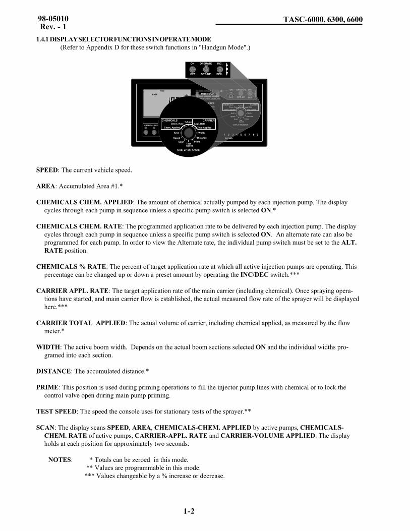
SPEED: The current vehicle speed.
AREA: Accumulated Area #1.*
CHEMICALS CHEM. APPLIED: The amount of chemical actually pumped by each injection pump. The displaycycles through each pump in sequence unless a specific pump switch is selected ON.*
CHEMICALS CHEM. RATE: The programmed application rate to be delivered by each injection pump. The displaycycles through each pump in sequence unless a specific pump switch is selected ON. An alternate rate can also beprogrammed for each pump. In order to view the Alternate rate, the individual pump switch must be set to the ALT.RATE position.
CHEMICALS % RATE: The percent of target application rate at which all active injection pumps are operating. Thispercentage can be changed up or down a preset amount by operating the INC/DEC switch.***
CARRIER APPL. RATE: The target application rate of the main carrier (including chemical). Once spraying opera-tions have started, and main carrier flow is established, the actual measured flow rate of the sprayer will be displayedhere.***
CARRIER TOTAL APPLIED: The actual volume of carrier, including chemical applied, as measured by the flowmeter.*
WIDTH: The active boom width. Depends on the actual boom sections selected ON and the individual widths pro-gramed into each section.
DISTANCE: The accumulated distance.*
PRIME: This position is used during priming operations to fill the injector pump lines with chemical or to lock thecontrol valve open during main pump priming.
TEST SPEED: The speed the console uses for stationary tests of the sprayer.**
SCAN: The display scans SPEED, AREA, CHEMICALS-CHEM. APPLIED by active pumps, CHEMICALS-CHEM. RATE of active pumps, CARRIER-APPL. RATE and CARRIER-VOLUME APPLIED. The displayholds at each position for approximately two seconds.
NOTES: * Totals can be zeroed in this mode. ** Values are programmable in this mode.*** Values changeable by a % increase or decrease.
1-3
TASC-6000, 6300, 6600 98-05010Rev. - 1
1.4.2 DISPLAY SELECTOR FUNCTIONS IN SET UP MODE(Refer to Appendix D for these switch functions in "Handgun Mode".)
MID-TECH
MIDWEST TECHNOLOGIES, INC.
CHEMICAL APPLICATORS
1 2 3
ON
OFF
Alt.-Rate
TASC-6600TOTAL APPLICATION
SPRAYER CONTROL
1 2 3 4 5 6 7 8 9BOOMS
4 5 6
.
-Ac
Flow
RATE
Gal./
®
OFF SET- UP DEC.
ON OPERATE INC.
%Rate
DISPLAY SELECTOR
Speed
Area Width
Distance
Chem. Applied
Test Speed
Prime
Total Applied
Chem. Rate Appl. RateCHEMICALS CARRIER
Scan
MID-TECH
MIDWEST TECHNOLOGIES, INC.
ON
OFF
Alt.-Rate
TASC-6600TOTAL APPLICATION
SPRAYER CONTROL
1 2 3 4 5 6 7 8 9BOOMS
6
Ac
®
OFF SET- UP DEC.
ON OPERATE INC.
%Rate
DISPLAY SELECTOR
Speed
Area Width
Distance
Chem. Applied
Test Speed
Prime
Total Applied
Chem. Rate Appl. RateCHEMICALS CARRIER
Scan
%Rate
DISPLAY SELECTOR
Speed
Area Width
Distance
Chem. Applied
Test Speed
Prime
Total Applied
Chem. Rate Appl. RateCHEMICALS CARRIER
Scan
MID-TECH
MIDWEST TECHNOLOGIES, INC.
Ac
®
OFF SET- UP DEC.
ON OPERATE INC.
MID-TECH
MIDWEST TECHNOLOGIES, INC.
-Ac
®
OFF SET- UP DEC.
ON OPERATE INC.
OFF SET- UP DEC.
ON OPERATE INC.
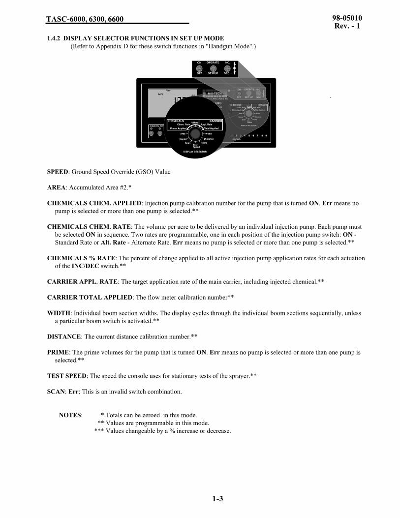
SPEED: Ground Speed Override (GSO) Value
AREA: Accumulated Area #2.*
CHEMICALS CHEM. APPLIED: Injection pump calibration number for the pump that is turned ON. Err means nopump is selected or more than one pump is selected.**
CHEMICALS CHEM. RATE: The volume per acre to be delivered by an individual injection pump. Each pump mustbe selected ON in sequence. Two rates are programmable, one in each position of the injection pump switch: ON -Standard Rate or Alt. Rate - Alternate Rate. Err means no pump is selected or more than one pump is selected.**
CHEMICALS % RATE: The percent of change applied to all active injection pump application rates for each actuationof the INC/DEC switch.**
CARRIER APPL. RATE: The target application rate of the main carrier, including injected chemical.**
CARRIER TOTAL APPLIED: The flow meter calibration number**
WIDTH: Individual boom section widths. The display cycles through the individual boom sections sequentially, unlessa particular boom switch is activated.**
DISTANCE: The current distance calibration number.**
PRIME: The prime volumes for the pump that is turned ON. Err means no pump is selected or more than one pump isselected.**
TEST SPEED: The speed the console uses for stationary tests of the sprayer.**
SCAN: Err: This is an invalid switch combination.
NOTES: * Totals can be zeroed in this mode. ** Values are programmable in this mode.*** Values changeable by a % increase or decrease.

1-4
TASC-6000, 6300, 660098-05010Rev. - 1
1.5 BOOM SECTION “ON/OFF” INDICATORS
MID-TECH
MIDWEST TECHNOLOGIES, INC.
CHEMICAL APPLICATORS
1 2 3
ON
OFF
Alt.-Rate
TASC-6600TOTAL APPLICATION
SPRAYER CONTROL
%Rate
DISPLAY SELECTOR
Speed
Area Width
Distance
Chem. Applied
Test Speed
Prime
Total Applied
Chem. Rate Appl. RateCHEMICALS CARRIER
OFF SET- UP DEC.
ON OPERATE INC.
1 2 3 4 5 6 7 8 9BOOMS
Scan
4 5 6
.
-Ac
Flow
RATE
Gal./
®
Boom IndicatorsInjection Pump Switches
The boom section on/off indicators (lower right, labeled BOOMS), indicate which boom sections are active (turned on).There is a maximum of nine boom section positions available.
1.6 INJECTION PUMP SWITCHES (TASC 6300 and 6600 only)(Refer to Appendix D for these switch functions in "Handgun Mode".)
The injection pump switches (lower left) are used to activate the injection pumps. Up to six separate injection pumps canbe controlled by the TASC console. Each pump has its own product switch and indicator light. When the switch is in thedown position, the injection pump is OFF. When the switch is in the ON position, the pump is pumping at the standardtarget rate, (the pump indicator light glows steadily). When the switch is in the Alt. Rate position, the pump is pumpingat the alternate target rate (the indicator light blinks and the console beeps periodically, indicating a non-standardoperation).
1.7 STATUS SWITCH
An externally mounted status switch can be used to control the injection pumps and the flow control valve. The switchmust present a positive voltage (+12.0 VDC) status on the green or white wire of the boom interface cable. As long asthis condition is present, TASC operates normally. If the voltage is interrupted, the TASC automatically stops theinjection pumps. At the same time, TASC either "CLOSE's" the flow control valve or "HOLD's" it in its current position,depending on the response selected by the operator (See Section 2.9).
The intent of this feature is to allow the operator to control the operation of TASC through the normal operation of thevehicle. The status switch can be used to sense the "ON"/"OFF" condition of the main vehicle pump or the switch maysense an implement "UP"/"DOWN" condition. Use of the status switch can lessen the operator's work load under certainconditions.

1-5
TASC-6000, 6300, 6600 98-05010Rev. - 1
1.8 GROUND SPEED OVERRIDE SWITCH
An optional ground speed override Switch can be used to temporarily operate the sprayer using a pre-selected "minimum(GSO) speed" rather than the actual speed registered by the ground speed sensor. The override feature is used to bringthe sprayer on line quickly when starting from a dead stop or to maintain an adequate spray pattern when the vehicle ismaneuvering at very low ground speeds. It can also be used to allow the operator to flush the sprayer from the cab withthe vehicle stopped.
The control console operates normally as long as the ground speed override switch condition is open (OFF). Wheneverthe override switch is closed (ON) and the actual ground speed is less than "GSO speed", the control console automati-cally selects the "GSO speed" value to control both carrier and injected chemical flow rates. As soon as the switchreverts to its normally open (OFF) condition, or the actual ground speed increases above the preset "GSO speed", thecontrol console controls flow rates on the basis of the actual ground speed.
CAUTION: When traveling at a speed slower than the GSO speed setting, this feature will cause the product to beapplied at a rate consistent with the GSO speed, rather than the true ground speed. When Ground Speed Over-ride is being used and the true ground speed is less than the preselected "GSO Speed", the console will sound analarm and the display will flash a "Too Slow" message to warn the operator of possible over application.

1-6
TASC-6000, 6300, 660098-05010Rev. - 1
This page purposely left blank

2-1
TASC-6000, 6300, 6600 98-05010Rev. - 1
2.0 CALIBRATION AND SET UP
The TASC Control Console must be calibrated for the various sensors used and programmed with certain informationbefore it is ready to be used. The calibration and set up processes are not difficult, however; they must be followedprecisely in order to get maximum accuracy out of the system.
2.1 ENGLISH AND METRIC UNITS
The TASC Control Console is capable of operating in two different units of measure, English and Metric.
2.1.1 UNITS FOR EACH POSITION(Refer to Appendix D for these units in "Handgun Mode".)
FUNCTION U.S. METRICSpeed Miles/Hour (MPH)* Kilometers/Hour (KPH)*Area Acres (-Ac)* Hectares (-Ha)*Chem. Applied Ounces-U.S. Gallons (TOTAL/Oz)*# Liters (TOTAL/Liters)*#
Chem. Rate Ounces/Acre (Oz-Ac)*@ Liters/Acre (RATE/Liters-Ha)*@
Appl. Rate U.S. Gallons/Acre (Flow/RATE Liters/Hectare (Flow/RATE/ GAL./ -Ac)* Liters-Ha)*
Total Applied U.S. Gallons (TOTAL/Flow/Gal.)* Liters (TOTAL/Flow)*Width Inches-Feet (TOTAL/Boom/Ft.)* Meters (TOTAL/Boom/Meters)*Distance Feet-Miles (Dist./Ft.)*** Meters-Kilometers (Dist.)*Prime Ounces (Oz) Liters (Liters)Test Speed Miles/Hour (MPH) Kilometers/Hour (KPH)
* Items in parenthesis are the abbreviations that appear on the screen. ** No units displayed*** No units displayed after roll over of feet to miles or meters to kilometers # TOTAL when channel in Non-Peristaltic @ -Ac when channel is in Non-Peristaltic
2.1.2 CHANGING UNITS
To change units, set the Mode switch to OPERATE and the Display Selector to SPEED. The current speed units are bedisplayed. Holding the INC/DEC switch down for approximately 5 sec.causes the display to alternate between U.S andMetric modes (MPH and KPH). The mode being displayed when the INC/DEC switch is released will be selected.
2.2 PERISTALTIC AND NON-PERISTALTIC INJECTION PUMP MODESSettingg Channel 1 - 6 Drive Method (TASC 6300/6600 Only)
The TASC 6300 and 6600 Chemical Applicator channels (1 - 6) can use two different drive methods, depending on thetype of equipment being controlled by the individual channel. "Peristaltic Drive" is used for peristaltic injection pumps."Non-Peristaltic Drive" is for future development. You should select the "peristaltic" drive method at this time.
NOTE: PLEASE READ THROUGH THE FOLLOWING SECTIONSCOMPLETELY BEFORE YOU BEGIN CALIBRATION!

2-2
TASC-6000, 6300, 660098-05010Rev. - 1
A. Use the following switch settings to select the desired drive method (You should have to do this only onceunless you change your equipment configuration.).
Power OFFMode selector SET-UPDisplay selector DISTANCE
B. Turn the rate selector switches, for any channels (1 - 6) that you want set to non-peristaltic to "ON". Anychannels left "OFF" are set to the peristaltic mode.
C. Hold the INC/DEC switch down while turning on the TASC power. After completing the start up routine, thedisplay settles on a series of o's and -'s. The o's correspond to the channels that are set to non-peristaltic driveand the -'s indicate peristaltic channels.
o o -
Indicates channel 1 and 2 are set to non-peristaltic drive and channel 3 is set for peristaltic.
D. If it is ever necessary to reset the channel configuration, simply repeat the above procedure selecting the desiredswitch configuration.
E. Whenever the TASC power is turned ON, the console momentarily displays the drive status of the chemicalapplicator channels (unless all channels are in peristaltic mode).
2.3 SETTING APPLICATION RATES
2.3.1 SETTING CARRIER APPLICATION RATE
TASC is designed to maintain a constant, preselected application rate for the carrier, including chemical, as it exits thesprayer. In order for TASC to do this, the operator must enter the desired carrier application rate. NOTE: The minimumCarrier Rate must exceed the total Chemical Rate by at least one Gal/Ac (L/Ha).
A. Set the console switches to the following positions:
Power ONMode Selector SET-UPDisplay Selector CARRIER, APPL. RATE
The display shows the current Carrier plus Chemical application rate (Gal/Ac or L/Ha).
B. Use the INC/DEC switch to set the value displayed to the new desired rate.
NOTE: Setting the Carrier Application Rate to 0.0 shuts off the flow control function.
2.3.2 SETTING CHEMICAL APPLICATION RATE
The TASC-6300 and 6600 consoles are designed to maintain a preset injection rate for each injection pump. To do this theoperator must enter the desired Application Rate (Oz/Ac or L/Ha) for each pump.
A. Set the console switches to the following positions:
Power ONMode Selector SET- UPDisplay Selector CHEMICALS, CHEM. RATEPump Switch #1 CENTER, ON POSITION

2-3
TASC-6000, 6300, 6600 98-05010Rev. - 1
The display shows the current Standard Application Rate (Oz/Ac or L/Ha) for Pump #1.
B. Use the INC/DEC switch to set the value displayed to the desired rate.
Example: 64.0 for 64 Fluid Oz. (2 qts.) per acre, (See Appendix A, Fluid Oz. Conversion Chart). Remember this is theactual chemical rate and bears no relationship to the carrier rate.
C. Repeat steps A and B for the remaining injection pumps, turning off each pump off before setting the next one.
NOTE: The Mode switch must be moved back to OPERATE for the new rate to be registered by the console.
2.3.3 SETTING ALTERNATE CHEMICAL APPLICATION RATE
The TASC-6300 and 6600 consoles are also designed to maintain a preset alternate rate for each injection pump. To dothis the operator must enter the desired Alternate Rate (Oz/Ac or L/Ha) for each pump.
A. Set the console switches to the following positions:
Power ONMode Selector SET- UPDisplay Selector CHEMICALS, CHEM. RATEPump Switch #1 UP, ALT. RATE POSITION
The display shows the current Alternate Application Rate (Oz/Ac or L/Ha) for Pump #1.
B. Use the INC/DEC switch to set the value displayed to the desired rate. The alternate rate for injection pump #1 isnow established.
C. Repeat steps A and B for the remaining injection pumps, turning each completed pump off before setting the nextone.
2.4 SETTING THE % RATE CHANGE OF THE CHEMICAL INJECTION PUMPS & THE CARRIER
This feature allows the operator to change the application rate of all active injection pumps or the carrier “ON THE GO”with a simple actuation of the INC/DEC switch. The amount of change each switch actuation makes is proportional to thevalue programmed into this position, (e.g. 5 = 5% change in the target rate). For example, if the chemical application rate isset at 64.0 ounces per acre, a single press of the INC. switch, with the Display Selector in "Chemicals, % Rate", results in achange of application rate to 67.2 ounces per acre (64.0 + 5% = 67.2). If the Display Selector had been in the "Carrier, Appl.Rate" position the carrier rate would have increased by 5% of its programmed rate.
NOTE: It is not recommended that the carrier rate be changed "on the go", while doing chemical injection, as momen-tary dramatic changes in chemical application rate can result.
A. Set the Console to the following positions;
Power ONMode Selector SET- UPDisplay Selector CHEMICALS, % RATE
The display shows the current % change value.
B. Use the INC/DEC switch to set this number to the desired % change.
NOTE: The rate change function will affect either the normal injection rate or the alternate injection rate, depending onwhich position the pump switch is in.

2-4
TASC-6000, 6300, 660098-05010Rev. - 1
2.5 SETTING BOOM WIDTHS
The Mid-Tech TASC Control Console is designed to automatically compensate for changes in the swath width, causedby activating or deactivating separate sections of a multi-section spray boom. For the console to automatically respond tochanges in swath width, it is necessary for the operator to set the individual boom section lengths into the console. Usethe following procedure to define the boom lengths to the console.
A. Set the Console to the following positions;
Power ONMode Selector SET-UPDisplay Selector WIDTHAll Boom Switches (external) OFF
The display cycles through each boom position and displays its current width in inches.
B. As each boom position appears on the display, use the INC/DEC Switch to set the display to the appropriatenumber of inches (meters) covered by that boom. Repeat for each section.
NOTE: Individual boom widths are entered in inches. The control console converts the total boom width to feetwhen it is switched back to the Operate Mode and the booms are turned on.
C. Set all unused boom sections (up to a total of nine) to a width of zero “0” inches. This insures that an accidentalboom switch ON does not affect the control console.
D. Let the boom width display cycle through the boom sections until it shows “Boom C”. As the width of “C” isdisplayed, it can be changed with the INC/DEC switch. This value is used by the control console to determinethe operating speed for the injection pumps during calibration sequences (as long as none of the boom switchesare turned ON). This value should be the normal operating width of the entire sprayer, in inches (meters).
E. The individual boom section widths are now established. Turn all boom switches to the ON position and returnto the OPERATE Mode, the new total boom width is displayed in feet (meters). If this does not agree with yourtotal sprayer width, check the individual boom widths (steps B and C).
2.6 FLOW METER CALIBRATION
TASC must be calibrated for the flowmeter being used. The calibration number required by TASC is the actual number ofelectrical pulses per gallon generated by the flowmeter for each gallon of liquid that passes through the flowmeter.Flowmeters are calibrated for water at the factory. This number is to be considered an initial value. The actual flowmetercalibration number for your system may differ due to plumbing variations or other factors. If you have any doubts as to theaccuracy of the flowmeter calibration number, a field calibration/catch test should be performed using the actualcarrier solution. This is particularly important if you are pre-mixing chemical with the carrier.

2-5
TASC-6000, 6300, 6600 98-05010Rev. - 1
2.6.1 TYPICAL FLOWMETER CALIBRATION NUMBERS (for water)
Standard Flowmeters
SIZE SUPPLIER CAL.# SIZE SUPPLIER CAL.# .75 inch (Mid-Tech) 396.9 3.00 inch(Mid-Tech) 5.01.00 inch(Mid-Tech) 153.11.50 inch(Mid-Tech) 38.8 1.25 inch(Raven) 75.0*2.00 inch(Mid-Tech) 23.8 3.00 inch(Raven) 16.4*
Mid-Tech Rapid Check Flowmeters
SIZE RANGE CAL# SIZE RANGE CAL#1.00 inch0.75 - 5 gpm 3200 1.50 inch2.6 - 53 gpm 361.91.00 inch2.5 - 25 gpm 612.4 1.50 inch 9 - 90 gpm 155.21.50 inch2.5 - 16 gpm 800 2.00 inch 20.0 - 195 gpm 94.5
* Raven flow meters, use the factory calibration number divided by 10. All other flowmeters use the manufacturers'supplied information regarding the pulses per gallon (usually provided on a tag on the flowmeter).
Use the following procedure to enter the typical flowmeter calibration number.
A. Set the Console to the following positions;
Power ONMode Selector SET- UPDisplay Selector CARRIER, TOTAL APPLIED
B. Use the INC/DEC switch to select the desired flowmeter calibration number.
2.6.2 FLOW METER CALIBRATION PROCEDURE
Field calibration of the TASC flowmeter is relatively simple. Operators have successfully performed flowmeter calibrationsusing a second, calibrated, flowmeter, using a truck scale and calculating volumes based on weight and density of theliquid discharged, and by discharging into a marked, calibrated tank.
A method such as the following is recommended. It is necessary to pump and measure at least 100 gallons (400 liters) andas much as 500 gallons (2000 liters), depending on the accuracy required. The better the measurement accuracy of actualdischarge and the more material pumped, the more accurate is the resulting calibration. For example: an actual measure-ment accurate to within 5 gallons (20 liters) while pumping and measuring 500 gallons (2000 liters) yields an accuracy of 1%. A result within 5 gallons (20 liters) while using only 100 gallons (400 liters) results in an error of 5 %.
A. Disconnect the line to one of the booms and direct the output to an appropriate catch basin through a manuallyadjustable valve. Adjust the valve for smooth flow with no error messages on the console.
B. Verify that the boom switches and injection pump switches are OFF; turn the Control Console ON; select theSET-UP mode; rotate the display selector switch to CARRIER, TOTAL APPLIED.
C. The current flowmeter calibration number is displayed. Make sure it is the recommended initial calibration numberfor the flowmeter installed in the system (Refer to the metal tag attached to the flowmeter.). Use the INC/DECswitch to adjust as necessary.
D. Select OPERATE with the mode selector switch. Hold the DEC switch down for three to five seconds to zero theaccumulated gallons display.
E. If the "HOLD on All Booms OFF" function has been activated for carrier valve, reset it to "CLOSE". (See section2.9.2 of the manual if you are unsure about this; the factory setting is "CLOSE").

2-6
TASC-6000, 6300, 660098-05010Rev. - 1
F. Make sure there is enough liquid in the main tank to do the test; start the main carrier pump; rotate the displayselector switch to TEST SPEED; turn ON the boom switch. Allow the sprayer to discharge until the desiredamount has been pumped; turn OFF the boom switches.
G. Rotate the display selector switch to CARRIER, TOTAL APPLIED. If the total shown on the console agreeswith the total discharge actually measured, no further action is necessary. The flowmeter is already calibrated.
H. If the indicated volume pumped does not agree with the actual volume pumped, calculate a corrected calibrationnumber as follows:
(INDICATED AMOUNT / MEASURED AMOUNT) X OLD CAL. # = NEW CAL. #
I. Set the mode selector to SET-UP and correct the calibration number using the INC/DEC switch. Return the modeselector to OPERATE and the amount displayed should now match the amount measured. The flowmeter is nowcalibrated.
J. Write this number down for future reference. This is the number to use for these specific conditions (material andsprayer configuration).
K. Further fine tuning of the calibration can be done based on field spraying experience. If liquid is consistently leftover after spraying a known number of acres, adjust the calibration number up slightly. If there is consistentlytoo little liquid to cover the desired acres, adjust the calibration number down slightly.
RECORD THE FLOW METER CALIBRATION NUMBER HERE:
2.7 DISTANCE CALIBRATION, GROUND SPEED SENSOR
2.7.1 GENERAL CONSIDERATIONS AND INITIAL CALIBRATION NUMBERS
It is important to field calibrate the distance sensor to insure optimum accuracy! The distance calibration must beperiodically checked. This is especially important if the sensor has come loose or been repositioned (Radar Sensor), or ifthe tires have been changed (Wheel and Speedometer Sensor).
Use the following initial calibration settings to get started. For the radar this number will be pretty close. For the wheelspeed sensor and the speedometer sensor the adjustment to this initial calibration number may be very large, dependingon the configuration of the vehicle.
Dj RADAR - 1000 MID-TECH COMPACT RADAR - 779WHEEL SENSOR & SPEEDOMETER SENSOR - 3500
A. Set TASC switches to the following settings:
Power ONMode Selector SET-UPDisplay Selector DISTANCE
The display now shows the current distance calibration value.
If the measured amount is more than the indicated amount,the calibration number should decrease. If the measuredamount is less than the indicated amount, the calibrationnumber should increase.

2-7
TASC-6000, 6300, 6600 98-05010Rev. - 1
B. Use the INC/DEC switch to select the initial distance calibration value suggested. You are now ready to performthe distance calibration.
2.7.2 DISTANCE CALIBRATION PROCEDURE
The following procedure is recommended by MIDWEST TECHNOLOGIES for establishing an accurate distance calibra-tion. NOTE: All pump and boom switches should remain OFF during the entire procedure.
A. Fill the main tank 1/2 full of water, to approximate actual load conditions. This minimizes the effect on the radarmounting angle and/or actual working diameter of the tires as the main tank empties.
B. Measure out a known distance of 400 ft. (150 m) or more in a field or roadway. Make it an easy place to maneuverthe vehicle. The longer the distance, the more accurately the test can be performed. Keeping the distance in evenhundreds of feet will make the calculations easier.
C. Drive the vehicle to the starting point of the distance range and stop.
D. Turn the Display Selector to the DISTANCE position and the Mode Select switch to SET-UP. The consoledisplays the current Distance Calibration Number. Record this number for future reference. As an example,assume this number is 1000.
E. Return the Mode Select switch to OPERATE and check to see that the accumulated distance is set at zero. If not,reset it to zero using the INC/DEC switch.
F. Start driving. Drive the vehicle at a speed of between 5 and 10 mph (8 - 16 kph). The distance start to accumulatein the display.
G. Stop the vehicle at the end marker. The display shows the accumulated distance. Compare this distance to theactual Measured distance, to determine how much of a correction is necessary. For example, if an accumulateddistance of 396 ft. (149 m) is shown after driving over a 400 ft. (150 m) range, the error in the distance calibrationis 1.0% (.7%).
H. Calculate the new Distance Calibration Number using the following formula:
(Measured distance/Accumulated distance) x Old DC# = New DC#
If the accumulated distance is less than the measured distancethe new Cal# will be larger.
Example: (400 / 396) x 1000 = 1010, the New DC#
NOTE: The same procedure is used, regardless of the type of distance sensor .
RECORD THE DISTANCE CALIBRATION NUMBER HERE:
2.8 INJECTION PUMP CALIBRATION (TASC-6300 & 6600 ONLY)
The pump calibration procedure "fine tunes" the precision injection pumps to ensure the highest possible accuracy of theTASC-6300 or 6600 system for your sprayer. It is important to understand that each of the injection pumps installed on aparticular sprayer must be separately calibrated. It is also important to periodically check the calibration of the individualpumps to ensure they continue to perform properly. Checking the calibration is particularly important when the tubing inthe pump chamber has been replaced or when the system is being activated after an extended downtime.

2-8
TASC-6000, 6300, 660098-05010Rev. - 1
2.8.1 TYPICAL PUMP CALIBRATION NUMBERS, PC#
The pump calibration number (PC#) is a value that relates to the volume of chemical output during each revolution of theinjection pump and is used by the TASC Control Console to determine each pump’s actual discharge rate. Pump calibra-tion numbers will differ slightly from one pump to the next due to variations in plumbing, tube size, pump chambers, etc.
The following values are typical PC#’s you can expect to see after performing the field calibration procedure. If your pumpcalibration number differs from the typical range, check the calibration. Use these numbers for your initial pump calibra-tion numbers, before conducting the actual prime or pump calibration procedure.
MODEL # DESCRIPTION TYPICAL PC# RANGEISC-20 PUMP 0.2 to 20-Oz./Min. (1/4"Dia. Tube) 32.0 27/37ISC-50 PUMP 2.6 to 53-Oz./Min. (1/4"Dia. Tube) 110.0 100/120ISC-50 PUMP 1.5 to 29-Oz./Min. (3/16"Dia. Tube) 65.0 58/72ISC-100 PUMP 1.0 to 100-Oz./Min. (3/8"Dia. Tube) 145.0 130/160ISC-150 PUMP 1.5 to 150-Oz./Min. (3/8"Dia. Tube) 145.0 130/160ISC-200 PUMP 6.4 to 128-Oz./Min. (3/8"Dia. Tube) 285.0 256/314ISC-200 PUMP 10.7 to 213-Oz./Min. (1/2"Dia. Tube)485.0 436/534ISC-350 PUMP 22.0 to 220-Oz./Min. (3/8"Dia. Tube)285.0 256/314ISC-350 PUMP 37.0 to 370-Oz./Min. (1/2"Dia. Tube)485.0 436/534
2.8.2 PUMP CALIBRATION, FIELD PROCEDURE
The following field procedure is recommended to check or calibrate the injection pumps. This procedure requires a catchbasin or container of at least 60 Oz. with graduation marks. In this example, a 56 Oz. test is described. There is nothingmagic about the 56 Oz. number, in fact, collecting more material leads to smaller measurement errors. However, it isimportant to get a very accurate measurement of the volume of fluid (Fl. oz.) collected. In this example we will be calibrat-ing Pump #1, the procedure is the same for all pumps.
NOTE: MID-TECH suggests doing all calibrations using water to keep the procedure as simple and safe as possible;however, it may be necessary to calibrate with the actual chemical if it is an extremely thick, heavy or viscous fluid.
Check the current Pump Calibration Number and Application Rate (pump to be calibrated), Boom Width “C”, and TestSpeed values. These should be typical for your sprayer operations. If not, reset them to a typical value, (Refer to Sections2.3.2. & 2.5 to view and enter these values).
The calibration is conducted with the vehicle STOPPED and the main carrier pump NOT running. To safeguard againstbackflushing and siphoning, SHUT OFF the feed line from the main tank to the main pump.
NOTE: Thoroughly flush all injection lines and fill with clean water before performing calibration procedure.
A. Make sure all chemical containers are filled with fresh, clean water, and they are connected to the proper injectionpumps. Turn all booms OFF (boom width "C" is used.)
B. Set the control console switches as follows:
Power ONMode Selector OPERATEDisplay Selector CHEMICALS, CHEM, APPLIEDPump Switch #1 CENTER, ON POSITION
The accumulated volume for pump #1 will be displayed.
TO ENSURE AN ACCURATE CALIBRATION, PLEASE FOL-LOW THE PROCEDURE EXACTLY!

2-9
TASC-6000, 6300, 6600 98-05010Rev. - 1
C. Use the INC/DEC switch to reset the display to zero. Select SET-UP with the Mode Selector switch. The currentpump calibration number is displayed. Now go back to the pump and perform the flush operation.
D. Disconnect the discharge line on the injection pump from the sprayer. (On most installations this can be accom-plished by using a calibration valve to redirect the discharge flow.)
E. Open the cover on pump # 1 and place the calibration magnet on the “*” target depicted on the motor controlmodule. Allow the pump to run until satisfied the lines are flushed and filled with liquid. Remove the calibrationmagnet.
F. Return to the control console and select OPERATE with the Mode Selector switch. Use the INC/DEC switch tozero the accumulated volume for pump #1 and again select SET-UP with the Mode Selector switch. Now go backto the pump and perform the test.
G. Be sure the supply tank for the pump being calibrated contains more than enough material to conduct the test.Direct the discharge line from the injection pump into the graduated container.
H. Place the calibration magnet on the "*" target on top of the pump control module and allow the pump to dis-charge into the calibration container. When enough material has been pumped, remove the calibration magnet.Verify the amount of liquid in the calibration container as observed on the marks on the side of the container (ie.56 oz)
I. Return to the console. Select the OPERATE Mode. The number displayed will be the “Indicated” Ounces fromPump #1. If the console reading agrees with the calibration container the pump is calibrated. If the consolereading is incorrect, calculate the new calibration number. For instance, if the Accumulated ounces reads 53instead of 56 (which we collected), then we would divide the Actual Ounces by the Indicated Ounces andmultiply that number by the old PC# to calculate the new PC#.
Actual Oz./Indicated Oz. x Old PC# = New PC#
If the Indicated Ounces is less than the Actual Ounces collected,the Cal# will increase.
Example: 56/53 x 145.0 = 153.2, the New PC#
J. To change the Pump Calibration Number, return to the SET -UP Mode and view the old Pump Calibration Number(145.0 for example).
K. Use the INC/DEC switch to increase the PC# from 145.0 to 153.2.
L. Set the Mode Select switch back to OPERATE and the accumulated ounces will again be displayed. The consolerecalculates the ounces accumulated and should now show the amount actually collected (56 in our example). Ifthe displayed value of accumulated ounces is still off by a significant amount, repeat the procedure.
M. Turn OFF pump #1. Connect the injection pump discharge line to the sprayer.

2-10
TASC-6000, 6300, 660098-05010Rev. - 1
N. REPEAT THIS PROCEDURE (steps B through M) FOR THE REMAINING PUMPS.
O. Record the Pump Calibration Numbers Here:
PUMP 1
PUMP 2
PUMP 3
PUMP 4
PUMP 5
PUMP 6
2.8.3 ESTABLISHING THE “PRIME” VOLUME FOR EACH INJECTION PUMP
The “PRIME” volume is the volume of material in the system, between the chemical tank and the injection point at themain boom supply line. Obviously, this volume will depend on the sizes of lines used, the size of the injection pump, andthe distance between the tank and the injection point. There are two methods of establishing the “PRIME’ value.
A. CALCULATING THE “PRIME” VALUE
Calculate the volume of fluid needed to completely fill the line and pump, and convert this volume to fluid ounces, anduse this calculated value directly. Calculate this volume using the following formula (all measurements in inches):
(Line diameter/2)2 X 3.1416 X Line length X 0.5541 = Volume in Fluid Ounces
For example, let’s suppose we have a system where the line from the chemical container to the pump inlet is 1/2 inchdiameter hose, 36 inches long. The pump tubing is 3/8 inch diameter, 25 inches long. And, the discharge line is 3/8 inchdiameter, 24 inches long. We want to calculate the volume, in ounces, needed to prime the line from the chemical containerto the discharge point.
(0.500/2)2 X 3.1416 X 36 X 0.5541 = 3.92 ounces(0.375/2)2 X 3.1416 X 25 X 0.5541 = 1.53 ounces(0.375/2)2 X 3.1416 X 24 X 0.5541 = 1.47 ounces
“PRIME” Volume = 6.9 ounces
(NOTE: This calibration procedure can be conducted with one ormore boom sections active.. This will not affect the accuracy of thecalibration, however; the console will not allow any further opera-tions until the active boom sections are turned "OFF". This ensuresthe vehicle does not begin to spray by mistake. A message "BOOMOFF" will be displayed to remind the operator to close the boomvalves.)

2-11
TASC-6000, 6300, 6600 98-05010Rev. - 1
B. DIRECT MEASUREMENT OF THE “PRIME” VALUE
Actually measuring the amount of fluid needed to prime the injection line is the second, and more accurate method, ofdetermining the “PRIME” value. To do this, first calibrate each injection pump using the procedure outlined in Section2.8.2.; then, operate the pump in a controlled manner, allowing its discharge to be collected and measured. Ordinarily, thisprocedure would only need to be done once, unless there are major changes to the plumbing on your sprayer.
NOTE: MID-TECH suggests you do all your calibrations using water to keep the procedure as simple and safe aspossible.
The following procedure ensures an accurate measurement of the volume of fluid needed to prime each injection pump. Itshould be followed exactly. The measurement is conducted with the vehicle stopped and the main carrier pump notrunning. To prevent backflushing and siphoning, shut off the feed line from the main tank to the main pump.
Check the current Pump Calibration Number and Application Rate (pump to be calibrated), Boom Width “C”, and TestSpeed values. These should be typical for your sprayer operations. If not, reset them to a typical value, (Refer to Sections2.3.2. & 2.5 to view and enter these values).
NOTE: Thoroughly flush all injection lines and fill with clean water before performing calibration procedure.
A. Make sure all chemical containers are filled with fresh, clean water, and they are connected to the proper injectionpumps. Make sure all boom switches are OFF.
B. Disconnect the injection lines at the injection point in the main boom supply line.
C. Set the Control Console switches as follows:
Power ONMode Selector OPERATEDisplay Selector CHEMICALS, CHEM, APPLIEDPump Switch #1 CENTER, ON POSITION (any individual pump can be selected)
The accumulated volume pumped by pump #1 will be displayed.
D. Use the INC/DEC switch to reset the display to zero. Select SET-UP with the Mode Selector switch. The currentpump calibration number is displayed. Now go back to the pump and perform the flush operation.
E . Open the cover on pump # 1 and place the calibration magnet on the “*” target depicted on the motor controlmodule. Allow the pump to operate until satisfied the lines are flushed and filled with fresh liquid. Remove themagnet to stop the pump.
F. Return to the control console and select OPERATE with the Mode Selector switch. Use the INC/DEC switch tozero the accumulated volume for pump #1 and again select the SET-UP mode with the Mode Selector switch. Thecurrent pump calibration number is displayed. Now go back to the pump and perform the catch test.
G. Add foam marker dye to the water in each chemical container.
H. Place a collection container, graduated in ounces, under the discharge tube for pump #1.(A rough calculation of “PRIME” vol. can be used to help chose the right sized container.)
I. Place the magnet provided on the “*” target on the pump control module. The pump will begin to operate.
J. Remove the magnet as soon as colored water begins to discharge from the tube. The pump will stop.
K. Read the volume of fluid collected in the graduated container. This volume is the “PRIME” value for pump #1.Record this value.

2-12
TASC-6000, 6300, 660098-05010Rev. - 1
L. Proceed to measure the prime values for the remaining pumps, in sequence, using the procedure outlined in itemsC through K above.
M. When all measurements are complete, reconnect the pump discharge lines to the injection points in the mainboom supply line.
N. Use the procedure outlined in 2.8.4. below, to set the recorded “PRIME” values into the console.
O. Record the Prime numbers Here:
Pump #1 - Prime# Pump #4 - Prime#
Pump #2 - Prime# Pump #5 - Prime#
Pump #3 - Prime# Pump #6 - Prime#
2.8.4 SETTING “PRIME” VALUES IN THE CONSOLE MEMORY
A. Set the console switches to the following positions:
Power ONMode Selector SET- UPDisplay Selector PRIMEPump Switch #1 CENTER, ON POSITION
The display will show the current prime volume (Oz) for Pump #1
B. Use the INC/DEC switch to choose the value desired. Turn Pump #1 switch OFF.
C. View and reset all injection pump PRIME values using the procedure in A and B above.
2.9 SETTING THE "HOLD/CLOSE" RESPONSE OF THE FLOW CONTROL VALVE
The operator can select a "HOLD" or "CLOSE" response of the Flow Control Valve to both the Status Switch and to anAll Booms "OFF" condition. These responses are independent of each other, allowing the operator to select a "HOLD"condition for one and a "CLOSE" for the other. Careful consideration should be given to both conditions and theappropriate response selected for your spraying application. NOTE: In both cases the Chemical Injections Pumps willstop automatically.
2.9.1 STATUS SWITCH
When the "HOLD" condition is selected, activation of the Status Switch will HOLD the Flow Control Valve in its currentposition. The valve does not close even though the vehicle speed may drop to zero. Then, when the Status Switch isdeactivated the Flow Control Valve is already open and Carrier Flow is instantaneous. This response assumes that someother device is used to stop the carrier flow.
When the "CLOSE" condition is selected, activation of the Status Switch automatically causes the Flow Control Valve toCLOSE. This response is preferred when it is necessary to use the Flow Control Valve to stop the Carrier Flow.

2-13
TASC-6000, 6300, 6600 98-05010Rev. - 1
A. To select the desired response set the console switches to the following positions:
Booms OFFInjection pumps OFFPower ONMode Selector OPERATEDisplay Selector CARRIER, TOTAL APPLIED
B. Holding the INC Switch up displays the current selected response.
C. Continuing to hold the INC Switch up causes the display to cycle between the two options at about threesecond intervals.
D. When the desired response is shown, release the INC switch.
2.9.2 ALL BOOMS "OFF"
When the "HOLD" condition is selected, all booms "OFF" hold's the Flow Control Valve in its current position. Thevalve does not close even though the vehicle speed may drop to zero. Then, when the booms are selected "ON" again theFlow Control Valve is already open and Carrier Flow is instantaneous.
When the "CLOSE" condition is selected, all booms "OFF" will automatically cause the Flow Control Valve to CLOSE.This response would be preferred when it is necessary to use the Flow Control Valve to positively stop the Carrier Flow.
A. To select the desired response set the console switches to the following positions:
Booms OFFInjection pumps OFFPower ONMode Selector OPERATEDisplay Selector WIDTH
B. Holding the INC Switch up displays the currently selected response.
C. Continuing to hold the INC Switch up causes the display to cycle between the two options at about threesecond intervals.
D. When the desired response is shown, release the INC switch.
2.10 SETTING THE GROUND SPEED OVERRIDE "GSO" VALUE.
A. To set the desired GSO speed use the following steps:
Display Selector SPEEDMode Switch SET-UP
The console displays the current GSO Value.
B. Use the INC/DEC Switch to set the desired value. If you intend to use this feature, set the value to the minimumGround Speed desired when the GSO Switch is activated. This should be the minimum speed at which thesprayer can operate smoothly and provide a good nozzle pattern. NOTE: If you do not intend to use this feature,set this value to Zero (0.0).

2-14
TASC-6000, 6300, 660098-05010Rev. - 1
CAUTION: When traveling at a speed slower than the GSO speed setting, this feature will cause the Product to beapplied at a Rate consistent with the GSO speed, rather than the true ground speed, possibly resulting in seriousover application. When Ground Speed Override is being used, and the true ground speed is less than the pre-selected“GSO” Speed, the console will sound an alarm and the display will flash a “Too Slow” message to warn the opera-tor of possible over application.
2.11. SETTING AUTO POWER DOWN TIME
The console has an "Auto Power Down" feature which powers the console off after an operator selectable period (defaultis 30 min) has elapsed. If no input is received from the speed sensor or any console switch during this time the APDfeature is activated. The APD time can be set from 15 to 60 minutes. Selecting a period less than 15 minutes disables theAPD feature.
A. Use the following switch settings to adjust the Auto Power down time:
Power OFFMode selector SET-UPDisplay selector % RateHold the INC switch UP while turning the power on
The display will show the current Auto Power Down time.
B. Select the desired time using the INC/DEC switch.
C. Exit this set-up mode by moving the Display Selector to another position, the Mode Selector to OPERATE, orturning the console OFF and back ON.
NOTE: The “Auto Power Down Feature is only available on the CE version of the console (CE designation label on backof console). If you have the standard console model always turn the console power off when not in use to preventunnecessary drain on the battery.
2.12 REFLOW MODE
2.12.1. DESCRIPTION
The TASC Reflow Option changes the standard method of accumulating total volume applied. In the Reflow condition,the TASC Control Console can automatically, and accurately, accumulate total volume applied through a reflow sprayer(reference the reflow sprayer plumbing diagram in the appendix). In a reflow sprayer, the mixed product that ordinarilywould be sprayed is diverted back to the suction side of the main pump whenever an individual boom section is deacti-vated. The Reflow Option allows the TASC Control Console to adjust the flowmeter calibration constant in proportion tothe amount of flow actually escaping through the spray boom. When this adjustment is made, the calculation of totalapplied volume remains accurate.
The adjustment is described as follows:
Adjusted Cal # = (TOTAL BOOM WIDTH) / (SELECTED BOOM WIDTH) X (Cal #)
Whenever boom sections are brought on or off line, the TASC Control Console will adjust both the injection pumpmetering rates and the flowmeter calibration number in order to maintain the proper application rate, and an accuratemeasure of the total volume of material applied.

2-15
TASC-6000, 6300, 6600 98-05010Rev. - 1
2.12.2. REFLOW SET UP
Before operating the sprayer in the Reflow mode, there are some critical set-up steps which must be taken.
1. Using the methods recommended by the sprayer manufacturer, adjust the reflow bypass valves so that they will allowreflow at the same flow rate that the individual boom section would apply, if it were activated. For example: if the boomsection would ordinarily spray 1 gallon per minute at normal working pressure, then the reflow valve should beadjusted to reflow 1 gallon per minute, at the same pressure, when the flow to that boom section is diverted to thereflow line.
2. Make sure all reflow boom widths are properly established in the TASC Console (see section 2.5).
3. Make sure that boom section "C" is set to the total width of the boom when all reflow boom sections are operating. Forexample; if the sprayer is using 6 booms in the reflow operation, each boom being 10 feet in length, the total BoomWidth "C" is be 720 inches.
4. All TASC Console boom positions which are not being used in the reflow spraying operation, must be set to 0.0 width.For example; if only booms 1 through 6 are being used for reflow, booms 7, 8 and 9 must be set to zero for the TASCConsole to work properly.
5. Make sure the proper Flow Meter Calibration number is entered in the TASC Console. See section 2.6. of the TASCManual (Flow Meter Calibration).
2.12.3. ESTABLISHING THE REFLOW OPTION
The following procedure will establish the Reflow in the TASC Console. Once the Reflow Option has been selected, theConsole will remain in the Reflow Option, even through normal Power Down and Power Up, until Reflow is cancelled.
Power OFFAll pumps OFFAll booms OFFDisplay Selector CARRIER, TOTAL APPLIEDMode Switch SET-UPHold INC./DEC. Switch to INC. while turning Power ON
The TASC Console powers up and displays its initial test sequence and the software level installed. After approximatelytwo seconds, the display reads "rEFLO", and that message continues to be displayed until the INC. Switch is released.The TASC System is now set to the Reflow Option.
When the INC. Switch is released, the display shows 0.0 for the flow meter calibration number. When all reflow boomsections are turned "ON", the flow meter calibration number is displayed normally. As boom sections are turned "OFF",the flow meter calibration number will increase proportionately to the boom width which is still active.
2.12.4. CANCELLING THE REFLOW OPTION
The Reflow Option is cancelled with the following procedure.
Power OFFAll boom switches OFFAll product pumps OFFDisplay Selector CARRIER, TOTAL APPLIEDMode Switch SET-UPWhile holding the INC./DEC. Switch to DEC, turn Power ON

2-16
TASC-6000, 6300, 660098-05010Rev. - 1
The TASC Console display cycles through its normal Power Up testing routine and momentarily displays the softwarelevel installed. After about two seconds the display changes to "Stnrd", and remains in this condition until the DEC.Switch is released. The Console then displays the current Flow Meter Calibration Number.
The TASC System is now back to its standard configuration. The system remains in standard until the Reflow Option isactivated again.
2.12 OPERATING UNDER EXTERNAL RATE COMMANDS
When the TASC 6000 series console is operating under external rate commands, it must be connected to the computerrunning the field mapping program, through a 405-0069-96V or 78-05077 Data Link. Minimum and maximum rates must beprogrammed into the Rate Switch STANDARD RATE and ALT.-RATE positions respectively and the Rate Switch mustbe placed in the Alt.-Rate position. The instructions, received with the Data Link, explain in more detail, how to set up thecontrol console and Data Link. NOTE: The "Percent Rate Change" function is disabled when operating in the "ExternalControl" mode.

3-1
TASC-6000, 6300, 6600 98-05010Rev. - 1
3.0. OPERATION
Under normal operating conditions, TASC is automatic. It performs precisely, according to the information and direc-tions it receives from the operator. It is important to verify that TASC has the proper instructions before beginningspraying operations each day.
3.1. NORMAL START UP AND OPERATION
A. CONSTANTS: With all boom switches in the OFF position, verify that the proper constants are still entered in theconsole. Refer to section 2.0. of this manual to review the procedure for entering these constants. It is a good idea towrite the constants down in a convenient location.
B. APPLICATION RATES: With all boom switches in the OFF position and the Mode Selector switch in the SET-UPposition, review the standard and alternate application rates for each injection pump, and the carrier application rate.Use the procedure outlined in Section 2.3 of this manual to select and change the rates as required.
C. ACCUMULATED AREA: If desired, the accumulated acres can be reset to zero by selecting AREA and holding theINC/DEC switch down until the display resets to zero. NOTE: There are two Area Accumulators, one in the OPER-ATE Mode and one in the SET-UP Mode. These can be zeroed independently to keep track of two separate areas.
D. ACCUMULATED VOLUMES: If desired, the accumulated volumes for the carrier, and for each chemical pump,can be reset to zero by selecting CARRIER, TOTAL APPLIED or CHEMICALS, CHEM. APPLIED while in thein the OPERATE Mode and using the INC/DEC switch to reset.
E. Now, TASC is ready to begin spraying. Set the Mode Selector Switch to the OPERATE position. If a TASC-6300 or6600 is being used, select the desired injection pumps by turning those injection pump switches to ON or Alt. Rate.Select an appropriate display using the Display Selector, AREA for example.
F. Start the carrier pump and pressurize the sprayer.
G. When you reach the starting point of the first swath turn the desired boom switches ON. TASC automatically controlsboth carrier and chemical application. If an area or volume accumulator is selected on the Display Selector, theaccumulator begins to register.
H. Upon reaching the end of the swath, turn the boom switches, or the Master Switch, to the OFF position to tempo-rarily stop spraying. All injection pumps and accumulators will stop. When the vehicle has been turned and is readyto start spraying on the next swath, turn the booms ON and the sprayer, injection pumps and accumulators start again.
3.2. CHANGING ACTIVE BOOM SECTIONS
The active boom sections can be changed at any time by turning the appropriate boom switches ON or OFF. TASCautomatically adjusts the carrier flow rate and the injection rate of each pump as individual boom sections are activatedor deactivated. When all the boom section switches, or the Master Switch, are OFF, the injection pumps are stoppedalso. This allows the operator to select active boom sections "ON THE GO”, while depending on TASC to apply theproper chemical rates on the area actually being sprayed.
3.3. SELECTING DIFFERENT CHEMICAL COMBINATIONS
The TASC-6300 or 6600 allows the operator to select different chemical combinations while spraying. This is done byactivating or deactivating the appropriate injection pumps.
Switching individual injection pumps ON cause the TASC-6300 or 6600 to activate those particular pumps at thepredetermined application rates you have selected. Switching an injection pump switch to the OFF position, positivelystops that particular injection pump. The TASC-6300 will control up to three individual injection pumps, while theTASC-6600 will control up to six pumps.
3-2
TASC-6000, 6300, 660098-05010Rev. - 1
3.4. CHANGING THE APPLICATION RATE “ON THE GO”
TASC allows the operator to change the Application Rate of the main carrier, or the rates of individual injected chemi-cals, “ON THE GO”, using the INC/DEC switch. The amount of change caused by each actuation of the INC/DECswitch is predetermined in the SET-UP Mode, (see Section 2.4).
We will use an illustration to demonstrate the ability to change application rates "On The Go".
3.4.1. CHANGING APPLICATION RATE OF THE MAIN CARRIER
The operator has chosen a desired application rate for the main carrier and entered this value into the TASC ControlConsole using the procedure outlined in Section 2.3.1 of this manual. Anticipating the need to increase or decrease theapplication rate, the operator has also established a % rate change, using the procedure described in Section 2.4 of themanual. As an example, assume the TASC Control Console has been set up to apply 10.0 gallons per acre of carrier witha % rate change set at 20%.
During normal spraying, the TASC Control Console maintains the application rate of the carrier at 10.0 gallons per acre.However, let’s suppose the operator is spraying an aqueous fertilizer as the carrier. A soil type change in the middle ofthe field requires a 40% higher application of fertilizer (carrier) in order to reach desired fertility levels. As the sprayercrosses into the new soil type, the operator selects CARRIER, APPL. RATE with the Display Selector. The displayshows the current application rate of the carrier, in this case 10.0 Gal./Ac. Cycling the INC/DEC switch up twiceincreases the application rate by 2 X 20% or 40%. The flow control valve opens until the flow meter measures 14.0gallons per acre.
None of the other TASC control functions are affected. Thus, a TASC-6300 or 6600 still controls the injected chemicalat the preset application rate, regardless of changes to the carrier application rate. The new carrier application rate ismaintained until a further movement of the INC/DEC switch calls for additional change, or a movement of the DisplaySelector away from the CARRIER, APPL. RATE position cancels the rate change. When the rate change command hasbeen cancelled, TASC resumes controlling the carrier application rate according to the target rate established by theprocedure in Section 2.3.1 of the manual.
NOTE: It is not recommended that the carrier rate be changed "on the go", while doing chemical injection, asmomentary dramatic changes in chemical application rate can result.
Operation at a changed carrier application rate is not a normal condition. TASC continuously alerts the operator that anabnormal rate function is selected. The alert is both visual (a flashing “% RATE” on the LCD display ) and audible (aperiodic “beeping” of the alarm).
3.4.2. CHANGING APPLICATION RATE OF THE INJECTED CHEMICALS (TASC 6300/6600 ONLY)
The operator has chosen a desired standard and alternate application rate for each injected chemical and entered thesevalues into the TASC Control Console using the procedure outlined in Section 2.3.2 and 2.3.3 of this manual. Anticipat-ing the need to simultaneously increase or decrease all injected chemical application rates, the operator has also estab-lished a % rate change of the chemical injection pumps, using the procedure described in Section 2.4 of the manual.
3.4.2.1. CHANGING ALL INJECTION RATES SIMULTANEOUSLY
The application rates of all active injection pumps can be changed simultaneously by selecting the CHEMICALS, %RATE function with the Display Selector and cycling the INC/DEC switch up or down to effect the change. The actualapplication rates of all the active injection pumps are changed by the predetermined percent. Changing the injection ratesof the active injection pumps do not affect the application rate of the main carrier. Thus, a TASC-6300 or 6600 stillcontrols the carrier application rate at the preset rate, regardless of changes to the injection application rate. The newinjection rate is maintained until a further movement of the INC/DEC switch calls for additional change, or a movementof the Display Selector away from the CHEMICALS, % RATE position cancels the rate change. When the rate change

3-3
TASC-6000, 6300, 6600 98-05010Rev. - 1
command is cancelled, TASC resumes controlling the injection application rate according to the target rate establishedby the procedure in Section 2.3.2 of the manual.
Operation at a changed chemical injection rate is not a normal condition. TASC continuously alerts the operator that anabnormal rate function is been selected. The alert is both visual (a flashing “% RATE, Pump” on the LCD display ) andaudible (a periodic “beeping” of the Sonalert).
3.4.2.2. ALTERNATE RATES FOR INDIVIDUAL CHEMICALS
The alternate application rate for any individual injection pump can be activated, at any time, by simply selecting theALT.-RATE position for that particular pump switch. The injection pump applies chemical at the alternate rate until thepump switch is moved back to the ON position or the OFF position. Selection of an alternate rate for a particularinjection pump does not affect the application rates of the other injection pumps or of the main carrier. If an injectionpump is operating at the alternate rate and a percent rate change is called for by the operator (see Section 3.4.2.1), thepercent change is applied to the alternate rate also.
Operation at a changed chemical injection rate is not a normal condition. TASC continuously alerts the operator that anabnormal rate function is selected. The alert is both visual (a flashing “% RATE, Pump” on the LCD display ) andaudible (a periodic “beeping” of the Sonalert).
3.5. PRIMING THE INJECTION LINES (TASC 6300/6600 ONLY)
Use the following procedure to “PRIME” the chemical injection pumps and lines prior to spraying.
A. Set the console switches to the following positions:
Power ONMode Selector OPERATEDisplay Selector PRIMEPump Switch # CENTER, ON POSITION.
(Any number of pumps may be selected at the same time.)
B. A series of five dashes (- - - - -) will appear on the display.
C. Hold the INC/DEC switch down for about five seconds. The display shifts to 0.0 Oz. The display cyclesthrough the pumps that have been selected.
D. Place the cal. magnet on the “*” target on one of the pump control modules. That pump begins to operate. Itautomatically stops when the preset prime volume is pumped. Remove the magnet and move to the next pump.Continue until all selected pumps are primed.
E. Return to the console, it is displaying the actual volume pumped by each selected pump during the primingoperation. As in step C., the display cycles through the pumps that are selected.
F. Select any normal position of the Display Selector Switch and TASC is ready to begin spraying.
3-4
TASC-6000, 6300, 660098-05010Rev. - 1
3.6. GROUND SPEED OVERRIDE
An optional Ground Speed Override Switch can be used to temporarily operate the sprayer using the "GSO Speed"instead of the actual speed registered by the Ground Speed Sensor, (See Sec. 2.10). The override feature is used to bringthe sprayer on line quickly when starting from a dead stop or to maintain an adequate spray pattern when the vehicle ismaneuvering at very low ground speeds. It can also be used to allow the operator to flush the sprayer from the cab withthe vehicle stopped.
The Control Console operates normally when the Ground Speed Override Switch is in the OFF (open) condition.
When the Override Switch is ON (closed) and the actual ground speed is less than the "GSO Speed", the ControlConsole automatically uses the "GSO Speed" value to adjust both Carrier and Injected Chemical flow rates. If the actualground speed increases above the preset "GSO Speed", the Control Console reverts to controlling flow rates based onthe actual ground speed.
Examples:
GSO Switch "GSO Speed" Actual Ground Speed Control Speed"OFF" 5 mph 6 mph 6 mph"OFF" 5 mph 4 mph 4 mph"ON" 5 mph 6 mph 6 mph"ON" 5 mph 4 mph 5 mph
CAUTION: When traveling at a speed slower than the GSO speed setting, this feature will cause the Product to beapplied at a Rate consistent with the GSO speed, rather than the true ground speed, possibly resulting in seriousover application. When Ground Speed Override is being used, and the true ground speed is less than the pre-selected “GSO” Speed, the console will sound an alarm and the display will flash a “Too Slow” message to warnthe operator of possible over application.
3.7. PRIMING THE MAIN PUMP AND BOOM
Use the following procedure to “PRIME” the main pump and boom lines prior to spraying (VERSION 2.8 and higher).
A. Set the console switches to the following positions:
Power ONMode Selector OPERATEDisplay Selector PRIMEPump Switches OFF
B. A series of five dashes (- - - - -) will appear on the display.
C. Hold the INC/DEC switch up for about three seconds. The main control valve opens and remains in thisposition. While operating in this mode, there is no accumulation of area, distance or carrier.
D. The main pump can be run, with the booms open, to prime the sprayer. TASC does not try to shut down thesprayer because it doesn't see any flow. The control valve remains "OPEN".
E. Select any normal position of the Display Selector Switch and TASC is ready to begin normal spraying.

3-5
TASC-6000, 6300, 6600 98-05010Rev. - 1
3.8. MANUAL OVERRIDE OF FLOW CONTROL VALVE
There may be times when it will be necessary to control the product flow manually (To run "Speed & Pressure", unloadthe carrier tank, etc.).
A. To enter this mode do the following:
MODE SELECTOR SWITCH CARRIER APPL. RATEMODE SWITCH SETUPUse INC/DEC SWITCH to set rate to 0.0MODE SWITCH OPERATE
B. Console reads "Flow Contl OFF Auto".
In this mode the Flow Control Valve only responds to the INC/DEC Switch. The valve moves toward full open as longas the INC Switch is being held up. Holding the DEC Switch down moves the valve toward full closed.
When in Manual Mode, carrier flow rate is monitored by turning the Display Selector to "Carrier Application Rate". Theflow rate reads out in gallons per minute, when the actual ground speed is less than one MPH, and in gallons per acrewhen ground speed is above one MPH.

3-6
TASC-6000, 6300, 660098-05010Rev. - 1
This page purposely left blank

4-1
TASC-6000, 6300, 6600 98-05010Rev. - 1
4.0. MAINTENANCE
Mid-Tech recommends the following maintenance to keep your TASC system operating at peak efficiency.
4.1. FLUSHING AND CLEANING
NOTE: It is important to keep your chemical applicator clean. Chemicals are becoming more potent and environmentalconsiderations are becoming more demanding. Keeping the equipment clean also makes it easier to maintain the vehicleand extends its working life.
Always refer to the chemical manufacturer's directions regarding cleaning and flushing.
As a general rule MID-TECH recommends the following:
A. Do not leave chemical in the injection pump or application lines overnight. The system should be flushed and cleanedat the end of each day's operation. Some chemicals actually bind to the walls of the containers and lines. The longer thechemical is in contact, the greater the possibility that this will occur. Bound chemical has been known to release duringsubsequent spraying operations with detrimental affects on the crop being sprayed. Flushing and cleaning so thatchemical is not left in the sprayer for long periods of time will make this less of a concern.
B. All of the injection pumps should be flushed daily, regardless of use. Running the pumps frequently helps to keep thepumps in good working order. Unless the injection line from the pump has a positive shut off valve, some of thechemical applied that day may have migrated up the injection line to the pump. Flushing all the pumps helps guardagainst contamination.
4.2. INJECTION PUMPS
For the best tube and pump life, clean and lubricate the flexible tubing in the injection pumps prior to each day’soperation (use only the Tube Lube from your supplier).
At the end of each day’s use, disconnect the line from the chemical tank (or turn off the valve at the outlet of thechemical tank) and remove the tube from the pump housing to prevent it from developing a hard spot under the roller.This is particularly important in cold weather or if the pump will not be operated again the next day.
4.2.1. WEEKLY PUMP MAINTENANCE
Check the flexible pump tubing carefully for wear each week during frequent operations. Check for cracking, side splits,or other signs of material fatigue. If any signs of deterioration are seen, the tubing must be replaced immediately(replacement tubing kits are available from your MID-TECH dealer).
CAUTION: BE SURE THE CHEMICAL LINES AREDISCONNECTED OR TANK VALVES ARE “OFF”, SOTHAT LIQUIDS CANNOT DRAIN OR SIPHON INTOTHE MAIN BOOM SUPPLY LINE WHEN THE TUBESARE REMOVED FROM THE INJECTION PUMP.
WARNING: Failure to follow the manufacturer's recommended cleaning andflushing procedures may result in chemical damage to crops receiving latertreatment. Of course, all flushed liquid should be collected and disposed of inaccordance with the applicable federal, state and local regulations for your area.

4-2
TASC-6000, 6300, 660098-05010Rev. - 1
If the tubing has been changed, the pump must be calibrated to ensure system accuracy. Use the field calibrationprocedure specified in Section 2.8.2 of this manual to calibrate the pump.
4.2.2. SEASONAL PUMP MAINTENANCE
Always replace the flexible pump tubing before beginning spraying operations each season. This is particularly impor-tant if the sprayer has been sitting idle for an extended period of time. Replacement tubing kits are available from yourMID-TECH dealer.
The Pump Calibration must be checked and calibrated at the start of each season. Use the field calibration procedurespecified in Section 2.8.2 of this manual to calibrate your pumps.
4.2.3. PERIODIC PUMP MAINTENANCE
Injection pumps should be checked for proper calibration anytime there is reason to suspect system accuracy or anytimethe internal pump tubing is changed. Use the field calibration procedure specified in Section 2.8.2 of this manual tocheck and calibrate the injection pump.
4.3. CONTROL CONSOLE
The console can be kept clean by wiping with a damp cloth and by covering unused connectors with the attached dustcovers. Console set-up information should be checked periodically (Refer to Section 2.0., Calibration and Set-Up.)
NOTE: It is unlikely that set-up information will require reentering. However, there have been rare cases of its beingdistorted by random electromagnetic interference. For this reason, Mid-Tech strongly recommends recording the currentset-up information in a convenient location and checking them daily, before operating the sprayer.
4.4. GROUND SPEED SENSOR
WHEEL SENSOR: Check the sensor daily for loose or bent fittings. Mud or trash build up can push the sensor out ofalignment or knock the magnets off. Repair or replace any damaged components immediately and calibrate the sensor(Refer to section 2.7, Distance Calibration).
RADAR SENSOR: Check the sensor daily to make sure the face of the sensor is relatively clean (no dirt build up) andthat the mounting bracket and hardware is tight and has not shifted in position. The sensor can be cleaned using a dampcloth. While inspecting and cleaning the radar speed sensor, take care not to look directly into the face of the unit. Theradar generates a low level microwave signal when it is operating and it may be dangerous to the eyes.
If it is suspected or found that the radar sensor mounting position has shifted, the mounting bracket must be tightenedand the sensor must be calibrated. (Refer to Section 2.7, Distance Calibration)
4.5. FLOWMETER
Prior to each day’s spraying, the flowmeter should be inspected to ensure there are no leaks around the attachmentfittings. At the end of the day, care should be taken to thoroughly flush the flowmeter with clean water.
The impeller type flowmeters supplied by MIDWEST TECHNOLOGIES are inherently rugged. However, continued usewill eventually wear the internal bearings and shafts until the flowmeter becomes inaccurate. Replacement kits areavailable. Contact your MID-TECH dealer for these parts.

4-3
TASC-6000, 6300, 6600 98-05010Rev. - 1
4.6. FLOW CONTROL VALVE
Prior to each day’s spraying, the flow control valve should be inspected to ensure there are no leaks around the attach-ment fittings. At the end of the day, care should be taken to thoroughly flush the flow control valve with clean water.
4.7. WIRING HARNESS
Most failures of electronic systems like the TASC are the result of broken wires or poor connections. Taking some timeto periodically inspect and clean the wiring harness will help prevent this type of failure.
Inspect the external cabling for abrasion, stretched or pinched wires. If damage is seen, reroute the cabling and wrap it toprotect it from further damage. If a broken wire is found, it can be temporarily repaired by stripping the wire back oneach side of the break, twisting it together and SOLDERING the connection' (Do not use acid core solder). The bareconnection must be well insulated with heat shrink material or electrical tape.
MID-TECH strongly recommends replacement of damaged cables as soon as possible. Once the cable insulation isdamaged, moisture and chemicals can work their way under the insulation and cause corrosion to the conductor. In theend, continued problems will be experienced with the cable if it isn’t replaced.
The connectors at the ends of the cables must be periodically inspected and cleaned. Use a non-lubricating spray solvent(such as a tuner cleaner) to clean the connections. Lubricating sprays leave a film which collects dirt and can eventuallylead to failure of the contact. If the contact is so dirty it must be wiped clean, use a non abrasive swab (like a Q-TIP),along with the solvent, to avoid wear to the connector contact.
Sometimes connectors become damaged or worn out from many years of service. In this case, contact your MID-TECHsupplier for a replacement connector kit.
BE CAREFUL THAT WATER OR SEDIMENT IS NOTTRAPPED IN THE FLOW METER, PARTICULARLYIN COLD WEATHER, AS DAMAGE TO THE MECHA-NISM MAY OCCUR.
BE CAREFUL THAT WATER OR SEDIMENT IS NOTTRAPPED IN THE FLOW CONTROL VALVE, PAR-TICULARLY IN COLD WEATHER, AS DAMAGE TOTHE MECHANISM MAY OCCUR.

4-4
TASC-6000, 6300, 660098-05010Rev. - 1
This page purposely left blank

5-1
TASC-6000, 6300, 6600 98-05010Rev. - 1
ERROR CODE CAUSE REMEDY
5.0 TASC ERROR MESSAGES, COMMON CONDITIONS AND SOLUTIONSFIRST Check the battery connections, this is the MOST common fault.
A required constant is set to zero.
Sometimes this is caused by poor powerconnections at the battery.
Flow control valve is fully open. Travel-ing too fast for desired application.
Nozzles too small for rate, speed andboom width. (Boom pressure reads high).
Too much product being diverted tosparge.
Strainer or nozzle screens plugged.(Boom pressure low - Main strainer.)(Boom pressure high. - Nozzle screens.)
If displayed at normal operating speedsthis may indicate a bad spot in the pumptubing which causes the pump to stall.
Pump tubing too small.
Speed and rates too low to do an accuratejob of product delivery.
Error three indicates the console is notreceiving any pulses from the flowmeter.
Check for actual flow in the product line,if none:
Err 0, Pump ?: Reset Cal# for that channel.The affected channel is shut down.
Err 0, Dist. Cal#: Reset distance Cal#. Sprayerwill shut down.
Err 0, Boom #: Reset boom widths (includingboom width C.
Slow down, or check hydraulic flow to anhydraulically driven pump.
Change to larger nozzles.
Reduce sparging or turn up product pumpoutput.
Clean screens.
Inspect tubing and replace if necessary. Ifreplaced, re-calibrate pump before using.
Change to larger tubing.
Speed up, change to smaller tubes or lowercapacity pumps.
Check Flow control/Boom connections on theback of the console. Secure if loose.
Turn product pump ON.
Check for empty tank.
Verify that the boom valves are opening.Check for power, ground, and proper signalpolarity.
Check for correct operation of hydraulic valvecontrolling the pump motor. Check for power,ground, and proper signal polarity.
Err 0
Err 1(PUMP F)(Main ProductPump)
(Flashing "TooFast")
(PUMP 1, 2, 3)
Err 2(Flashing "TooSlow")
Err 3(PUMP-F)(Main ProductPump)
(Shuts downsystem afterabout 15 seconds)
(Requires "AllBooms OFF","Imp. StatusOFF", or "zeroground speed" toclear)

5-2
TASC-6000, 6300, 660098-05010Rev. - 1
Err 3(PUMP-F)(Cont.)
(PUMP-1,2,3)Liquid injectionpumps
Err 4PUMP-1,2,3
TASC ERROR MESSAGES, COMMON CONDITIONS AND SOLUTIONSFIRST Check the battery connections, this is the MOST common fault.
ERROR CODE CAUSE REMEDY
If there is flow in the product line but noflowmeter signals registered.
Pump does not turn at all. Rate sensor isgenerating no signals.
Pump runs for 10 to 15 seconds andstops. Console is receiving no signalsfrom the rate sensor.
Console senses that the pump is runningwhen it shouldn't be.
Will shut down system after 5 secondsof Err 4. If ERR 4 corrects itself, thensystem will recover by itself. If ERR 4doesn't last for 5 seconds, then systemwill not be affected.
Carrier application rate has beenexceeding the target rate by 15% for atleast 10-15 sec. Valve is stuck.
Check for air lock in the product pump, causing nooutput. Purge pump using the Prime function.
Clear blockage in product strainer.
Check Flow control/Boom connections on the backof the console. Secure if loose.
Clear blockage of the flowmeter rotor.
Test flowmeter sensor & replace if faulty. See testprocedure in the service manual.
Check channel control connections on the back of theconsole. Secure if loose.
Check for power and ground at the pump motor. Ifno power, check fuse and battery connection for thepump driver module. If fuse and battery connectionscheck ok and there is still no power to the motor,replace the pump driver module.
Check for obstruction in the pump that may bekeeping it from turning.
Check channel control connections on the back of theconsole. Secure if loose.
Pump RPM sensor is faulty. Check sensor wiring,connections, and mounting location for properclearance.
If the pump is actually running when it is not turnedon, unplug the pump power cable at the battery andcall for service help.
If pump is not running, check sensor mounting forexcessive vibration and sensor wire routing to makesure it is not running near a source electrical pulseswhich could cause false rate signals to the console.
Check battery connections.
Verify that the flow control valve is responding.Check, at the valve connector, for the proper voltagesduring the OPEN and CLOSE commands to thevalve. Replace faulty wiring or the valve if necessary.

5-3
TASC-6000, 6300, 6600 98-05010Rev. - 1
This is often caused by loss of powerto the valve.
Incorrect switch sequence is selected onthe console.
Communications problem with pumpChannel slave board or Data Link.
Memory error.
This is often the result of a poorbattery connection.
The vehicle electrical system voltagehas fallen below about 10.0 VDC.
Internal diagnostics.
Unable to print.
Value to be displayed exceeds themaximum allowable size.
Occures when the vehicle is setting stillwith the GSO, booms and any injectionpump turned on.
The Display Selector on a TASC 6000console has been set to one of theCHEMICAL (injection pump) positionsand this type of console has no injec-tion capabilities.
Err 5PUMP-F
Err
Err C
Err E
Err L
Err n, hook(backward 7)
Err P
OFLO
- FLO
none(TASC 6000 Only)
TASC ERROR MESSAGES, COMMON CONDITIONS AND SOLUTIONSFIRST Check the battery connections, this is the MOST common fault.
ERROR CODE CAUSE REMEDY
Check fuse at battery and on valve (optional).Replace if defective.
Check wiring and battery connections.
Consult Operator's Manual for the correct switchsequence.
Return console to Mid-Tech for repairs.
Hold down the decrease switch until the alarmstops. Check to see which constants have been setto zero and re-enter the correct values.
Establish good ground and battery connections.This is the most common fault when system isacting erratically.
Check and service or replace the vehicle battery.
Check and service or replace the vehicle alternator/voltage regulator.
May appear from time to time. A momentaryappearance, followed by no other problems, can besafely ignored. If occurs frequently, or if comes onand stays on, contact your Mid-Tech dealer.
This message should appear only if you have aMid-Tech printer attached to the TASC console.Console has received a print request from theprinter but cannot respond until the current controlfunction is completed.
Hold down the decrease switch until the display re-sets to zero.
Error will clear as soon as the vehicle starts movingor GSO, booms or pumps are turned off.
Use a TASC 6300 or 6600 console if injectioncapabilities are required.

5-4
TASC-6000, 6300, 660098-05010Rev. - 1
This page purposely left blank

6-1
TASC-6000, 6300, 6600 98-05010Rev. - 1
6.0. EMERGENCY OPERATIONS
MIDWEST TECHNOLOGIES has strived to make TASC as fool proof and reliable as possible. However, we realizethat problems can occur. If the operator is experiencing a failure of the ground speed sensor, the main flow control valveor, the flow meter, the first step is to carefully check the wiring harnesses for obvious problems and follow the suggestedtroubleshooting advice outlined in Section 5.0. in this manual. Assuming there is no success in getting the failed compo-nent to respond, MIDWEST TECHNOLOGIES suggests the following procedures as a temporary measure until thecomponent can be fixed or replaced.
If the operator chooses to use any of the following procedures, he should recognize that the accuracy of applica-tion is reduced. If this reduced accuracy is acceptable these procedures will allow the operator to continue on atemporary basis.
6.1. GROUND SPEED SENSOR FAILURE
The TASC Control Console internally generates a speed signal when operated with the Ground Speed Override (GSO)feature activated and the sprayer moving. When the unit is operated in the GSO mode, TASC establishes the rate as ifthe vehicle were actually moving across the field at the programmed GSO speed. This feature can be used to operate thesprayer in the event of a failure of the speed sensor. Application rate accuracy is reduced when operating underthese conditions.
A. With the vehicle stopped, set the console switches to the following positions:
All booms OFFPower ONMode Selector SET UPDisplay Selector SPEED
Using the INC/DEC switch, set the GSO speed for the normal spraying speed, (See Section 2.10 foradditional information).
B. Set the Mode Selector switch back to OPERATE and make sure the appropriate chemical injection switchesare selected to the desired rate. Start the vehicle and proceed to the application area, accelerating to normalspraying speed (as close as possible to the GSO speed value). As the vehicle reaches the start of the desiredswath, turn on the booms and begin spraying.
C. TASC controls application of the carrier and the injected chemicals as if the vehicle were moving at theestablished GSO speed. The actual accuracy of application therefore depends upon the ability of the operator tomaintain the desired vehicle speed. If the vehicle is traveling at exactly the established GSO speed, the applica-tion is nearly exact. If the vehicle is traveling faster or slower than the established GSO speed, the applicationrate is under or over the desired rate by a proportional amount.
D. All TASC functions, other than responding to speed changes, operate normally. The console still keeps track ofthe total chemical and carrier applied by the sprayer, and the application rate responds normally to changes inboom width. The readout of instantaneous application rate is meaningless under these conditions.
E. The console display continues to flash "Too Slow", and an audible alarm sounds ,to indicate abnormal opera-tion.

6-2
TASC-6000, 6300, 660098-05010Rev. - 1
6.2. FLOW CONTROL VALVE FAILURE
The TASC can still be operated in the event of a flow control valve failure. To operate the sprayer, it is necessary tomanually adjust the flow control valve so that sufficient pressure is available to the booms to give a good spray pattern.Thus, there is no longer positive control over the main carrier flow, but; the chemical injection control system continuesto operate in a normal, fully controlled manner. Use the following procedure to manually position the flow control valve.Application rate accuracy is reduced when operating under these conditions.
A. Stop the sprayer, turn all booms OFF and put the console into Manual Override (see section 3.8).
C. Disconnect the flow control valve at the cable connector.
D. Use a nozzle chart to determine the boom pressure that gives the desired application rate of carrier at the targetspeed. Turn ON the normal boom sections and allow the carrier to spray. Manually rotate the stem of the flowcontrol valve (It may be necessary to remove the electric actuator to adjust the valve. Be sure to mark thevalve position before removing the power head.) and/or adjust the pump bypass valve to generate the desiredpressure downstream of the main carrier pump. Turn all boom sections OFF.
CAUTION: NEVER USE A SPARGE LINE WHILE OPERATING THE INJECTION PUMPS.
E. Turn ON the desired chemical injection pumps, to the rate desired, start the vehicle and proceed to the applica-tion area, accelerating to normal spraying speed. As the vehicle reaches the start of the desired swath, turn onthe booms and begin spraying. At this point, the operator is enjoying all the control and monitoring functions ofTASC, with the exception of positive control of the flow control valve.
F. All volumes and areas will accumulate normally. The chemical injection pumping rates respond normally tochanges in boom configuration, ground speed or pump application rate changes commanded by the operator.Carrier flow rate can be monitored by turning the Display Selector to "Carrier Application Rate". The flow ratereads out in gallons per minute, when the actual ground speed is less than one MPH, and in gallons per acrewhen ground speed is above one MPH. Thus, although this is at best a temporary solution to the valve failure,the application accuracy of the injected chemicals is still maintained.
G. To exit the Manual Override Mode reenter some Carrier Application Rate, other than zero, into the console.
6.3. FLOWMETER FAILURE
The TASC 6300 or 6600 can still be used to control chemical injection rates, even if the system experiences a failure ofthe flow meter. The procedure is very similar to operating without the flow control valve, except, in this instance, theflow control valve is cycled using a manual override procedure. Application rate accuracy is reduced when operatingunder these conditions.
A. Stop the sprayer, turn all booms and injection pumps OFF and put the console into Manual Override (seesection 3.8). Disconnect the flowmeter wiring harness at the first connector back from the flowmeter (3 pinconnector).
B. The Flow Control Valve now responds only to manually activated commands from the INC/DEC switch on theControl Console. The TASC console remains in this configuration until some Carrier Application Rate otherthan zero is entered into the Control Console
C. Use a nozzle chart to determine the boom pressure that gives the desired application rate of carrier at the targetspeed. Turn ON the desired boom sections and allow the carrier to spray. Adjust the boom pressure using theINC/DEC switch on the Control Console. INC opens the Flow Control Valve and DEC closes the valve. Therate of movement of the valve increases the longer the switch is held. Once the desired pressure is attained, turnall boom sections OFF.
CAUTION: NEVER USE A SPARGE LINE WHILE OPERATING INJECTION PUMPS.

6-3
TASC-6000, 6300, 6600 98-05010Rev. - 1
E. Turn ON the desired chemical injection pumps, to the rate desired, proceed to the application area, acceleratingto normal spraying speed. When the vehicle reaches the starting point of the desired swath, turn on the appro-priate boom switches and the sprayer starts to spray. At this point, the operator is enjoying all monitoringfunctions of TASC, with the exception of Carrier Application Rate and automatic control of the flow controlvalve. The console is not able to adjust carrier flow based on speed and boom width changes. The operator mustdrive at the correct speed and readjust the pressure manually if the boom width changes.
F. All volumes and areas, with the exception of CARRIER, TOTAL APPLIED, accumulate normally. Thechemical injection pumping rates respond normally to changes in boom configuration, ground speed or pumpapplication rate changes commanded by the operator. The carrier flow rate will read 0.0
G. To exit the Manual Override Mode reenter some Carrier Application Rate, other than zero, into the console.

6-4
TASC-6000, 6300, 660098-05010Rev. - 1
This page purposely left blank

A-1
TASC-6000, 6300, 6600 98-05010Rev. - 1
APPENDIX-ASYSTEM DRAWINGS
A.0 SYSTEM DRAWINGS

A-2
TASC
-6000, 6300, 660098-05010R
ev. - 1
TASC-6300 WIRING DIAGRAM
MIDWEST TECHNOLOGIES, INC.M-T 98251
WRC
+
Vehicle Battery(12 Volts)
TASC-6300 CONSOLE
Pump ControlCables
Ground Speed Sensor
Chemical Injection Pumps
Pump PowerCables
(To Boom Control Switches)Note: Line to be high (+12 V.dc) when valve is ON.
Boom Interface Cable
(To Implement Status Switch)Note: Shorting Plug must be istalled if the
Implement Status Switch is not used.
12 "3 "4 "5
(To Ground Speed Override Switch)
FlowmeterFlowmeter Interface Cable
Flow Control Valve
Valve Driver Cable
Flow Control Cable(404-0022)
Fuse,(10 amp)
Power Cable(401-0010)
Fuse,(5 amp)Red
Black Battery Cable(45-05037)
Fuse,(15 amp)
Neg.
Pos.Red
Blk.
BATTERY
Printer Module(Optional)
Data Logger(Optional)
Data Link(Optional)
EXTERNAL DEVICE DATALINK TASC CONSOLE
RTS CTS
INVALIDEXTERNALDATA
INVALIDCONSOLEDATA
INVALIDDATALINKDATA
LOCALCONTROL
EXTERNALENABLE
DATA FLOW DATA FLOW
MIDWEST TECHNOLOGIES, INC.
MID-TECH
DATALINK INTERFACE
POWER
OFF - ON - TEST
MID-TECH
1. LOG LOCATION2. LOG WEATHER3. LOG CHEMICALS10:45 AM 99%
MENU
7 8 9 START
4 5 6 FINISH
21 ENTER3
0
MID-TECH
Midwest Technologies, Inc.
PRINTER MODULE
MENU
POWER
OFF - ON - TEST
MID-TECH
CHEMICAL APPLICATORS
1 2 3
ON
OFF
Alt.-Rate TASC-6300
TOTAL APPLICATIONSPRAYER CONTROL
%Rate
DISPLAY SELECTOR
Speed
Area Width
Distance
Chem. Applied
Test Speed
Prime
Total Applied
Chem. Rate Appl. RateCHEMICALS CARRIER
OFF SET- UP DEC.
ON OPERATE INC.
1 2 3 4 5 6 7 8 9BOOMS
Scan
MID-TECH
MIDWEST TECHNOLOGIES, INC.
.
-Ac
Flow
RATE
Gal./
®
A.1 T
ASC
6300 SYSTEM
WIR
ING
DIA
GR
AM

A-3
TASC
-6000, 6300, 660098-05010R
ev. - 1TASC-6600 Control System
Carrier Pump
Boom Valves(Up to 9 Total)
CarrierTank
FLOW METER
In-Line Filter
AUTO-RANGEFLOW CONTROL VALVE
Bypass Line
Suction Line
GROUND SPEED SENSOR
TASC CONSOLE
To SprayBooms
CHEMICAL INJECTION PUMPS
CHEMICAL INJECTION TANKS
MID-TECH
MIDWEST TECHNOLOGIES, INC.
CHEMICAL APPLICATORS
1 2 3
ON
OFF
Alt.-Rate
TASC-6600TOTAL
APPLICATIONSPRAYER CONTROL
%Rate
DISPLAY SELECTOR
Speed
Area Width
Distance
Chem. Applied
Test Speed
Prime
Total AppliedChem. Rate Appl. Rate
CHEMICALS CARRIER
OFF SET- UP DEC.
ON OPERATE INC.
1 2 3 4 5 6 7 8 9BOOMS
Scan
4 5 6
TASC DATA LINKINTERFACE
COMPUTER WITH MAPPING PROGRAM
DGPS Receiverand antenna
MIDWEST TECHNOLOGIES INC.2733 East Ash Street
Springfield ILL - (217) 753-8424www.mid-tech.com
EXTERNAL DEVICE DATALINK TASC CONSOLE
RTS CTS
INVALIDEXTERNALDATA
INVALIDCONSOLEDATA
INVALIDDATALINKDATA
LOCALCONTROL
EXTERNALENABLE
DATA FLOW DATA FLOW
#405-0069 DATALINK INTERFACE
MID-TECH
MIDWEST TECHNOLOGIES, INC.
BOOM STATUS CABLE
®
Quick Fill PortMust be located between the Carrier Tank and Main Shut Off Valve.
Main Shut Off ValveMust be closed during refilling toprevent possible back wash ofchemicals into the Carrier Tank.
NOTES:* Injection Hose lengths should be kept to a minimum to reduce the amount of chemical required to fill the lines.
However, be sure to allow enough length, so as to not bind or stretch the hose when raising or lowering the boom.** Upstream injection for Non-Compatible Chemicals (e.g. Atrazine when using an Atrazine product and 2-4D).
There must be an in-line strainer between the Non-Compatible injection point and the other injection points
Fresh Water Flush Ports
A.2 TA
SC 6600 SY
STEM PLU
MBIN
G D
IAG
RA
M

A-4
TASC
-6000, 6300, 660098-05010R
ev. - 1
To Spray Booms
Boom ValvesTwo way
BYPASS ADJUST VALVE
INJECTION PUMP ASSEMBLIES
Quick Fill Port
CHEMICAL TANK ASSEMBLIESMICRO - TANK MICRO - TANK
Main Water/Carrier Pump
Flow Control Valve
Inline Filter
CALIBRATION VALVES
Calibration Ports
INJECTIONMANIFOLD
Flow Meter
Reflow line
TYPICAL REFLOW SPRAYER
PLUMBING DIAGRAM
REFLOW BYPASSVALVES
DO NOT REFLOW TO THE MAIN TANKWHEN OPERATING AN INJECTIONSPRAYER!
MAIN WATER TANK
A.3 R
EFLO
W PLU
MBIN
G D
IAG
RA
M

A-5
TASC-6000, 6300, 6600 98-05010Rev. - 1
1/8 Pint = 2 Fluid Ounces
1/4 Pint = 4 Fluid Ounces
1/3 Pint = 5.33 Fluid Ounces
1/2 Pint = 8 Fluid Ounces
2/3 Pint = 10.67 Fluid Ounces
3/4 Pint = 12 Fluid Ounces
1 Pint = 16 Fluid Ounces
1 1/2 Pint = 24 Fluid Ounces
2 Pints/1 Quart = 32 Fluid Ounces
2 1/2 Pints = 40 Fluid Ounces
3 Pints = 48 Fluid Ounces
4 Pints/2 Quarts = 64 Fluid Ounces
5 Pints = 80 Fluid Ounces
6 Pints/3 Quarts = 96 Fluid Ounces
7 Pints = 108 Fluid Ounces
8 Pints/4 Quarts/1 Gallon = 128 Fluid Ounces
1 Liter = 33.8 Fluid Ounces
LIQUID MEASURE WEIGHT TABLE (WATER)
1 Pint Water @ 60F = 16 Fl. Oz. = 1.042 Lbs.
1 Quart Water @ 60F = 32 Fl. Oz. = 2.084 Lbs.
1 Gallon Water @ 60F = 128 Fl. Oz. = 8.337 Lbs.
(Note: Fluid Ounces are not = Dry Weight Ounces)
A.4 FLUID OUNCES CONVERSION TABLE

A-6
TASC
-6000, 6300, 660098-05010R
ev. - 1
TASC 150 - 3/8" Tube
PUMP/TUBE SELECTION CHART for TASC SERIES PUMPS
7.4
TASC 350 - 1/2" Tube
370
4.4 220
TASC 350 - 3/8" Tube
4 213
TASC 200 - 1/2" Tube
2.5 128
.6
20.4
29.9
TASC 50 - 3/16" Tube
53
TASC 50 - 1/4" Tube
(EX
AM
PL
E
69.8
)PU
MP
NO
.-T
UB
E S
IZE
MAX. FLOW RATE (Oz. / Min.)
1 10 20 30 40 50 100 150 200 250 300 350 40002 4 6 8 .2 .4 .6 .8
NOTE:
Flow Ranges shown are Optimum values.
Locate 69.8 on the horizontal axis of the chart, then draw a vertical line intersecting the Pump/Tube Sizes.In this example, you would need at least a TASC #100 or larger pump.
EXAMPLE:
Max. Flow Rate = Max. Boom Width x Max. Speed x Appl. Rate x .00202
= 36 Ft. x 15 MPH x 64 Oz./Acre x .00202= 69.8 Oz./Min.
(Oz./Min.) (Feet) (MPH) (Oz./Acre) (Conv. Factor)
2 100
TASC 100 - 3/8" Tube
3 150
TASC 20 - 1/4" Tube
.2
.3
.5
1
1.5
1.3
2.1
Accurate control will be maintained at lower values.
2.2
3.7
1.0
TASC 200 - 3/8" Tube
A.5 TU
BE SELECTIO
N C
HA
RT

B-1
TASC-6000, 6300, 6600 98-05010Rev. - 1
APPENDIX-BSYSTEM OVERVIEW

B-2
TASC-6000, 6300, 660098-05010Rev. - 1
B.0. SYSTEM OVERVIEW
Mid-Tech has drawn upon many years of experience in electronically controlled chemical application to design andbuild this spraying system. We rely on the experiences of our users as well as ourselves to help us continually improveour systems. Please contact us to let us know what you like or don’t like about the TASC. We appreciate your com-ments, and THANK YOU for purchasing a MIDWEST TECHNOLOGIES Total Application Sprayer Control (TASC).
B.1. THE TASC SYSTEM CONTROLS BOTH CARRIER FLOW AND CHEMICAL INJECTION RATES
TASC is available in three different models, depending on the operator’s requirements. These models are the: TASC-6000, TASC-6300, or TASC-6600.
TASC-6000TOTAL APPLICATION SPRAYER CONTROL
%Rate
DISPLAY SELECTOR
Speed
Area Width
Distance
Chem. Applied
Test Speed
Prime
Total AppliedChem. Rate Appl. Rate
CHEMICALS CARRIER
OFF SET- UP DEC.
ON OPERATE INC.
1 2 3 4 5 6 7 8 9BOOMS
Scan
MID-TECH
MIDWEST TECHNOLOGIES, INC.
.
-Ac
Flow
RATE
Gal./
®
CHEMICAL APPLICATORS
1 2 3
ON
OFF
Alt.-Rate TASC-6300
TOTAL APPLICATIONSPRAYER CONTROL
%Rate
DISPLAY SELECTOR
Speed
Area Width
Distance
Chem. Applied
Test Speed
Prime
Total Applied
Chem. Rate Appl. RateCHEMICALS CARRIER
OFF SET- UP DEC.
ON OPERATE INC.
1 2 3 4 5 6 7 8 9BOOMS
Scan
MID-TECH
MIDWEST TECHNOLOGIES, INC.
.
-Ac
Flow
RATE
Gal./
®
MID-TECH
MIDWEST TECHNOLOGIES, INC.
CHEMICAL APPLICATORS
1 2 3
ON
OFF
Alt.-Rate
TASC-6600TOTAL APPLICATION
SPRAYER CONTROL
%Rate
DISPLAY SELECTOR
Speed
Area Width
Distance
Chem. Applied
Test Speed
Prime
Total Applied
Chem. Rate Appl. RateCHEMICALS CARRIER
OFF SET- UP DEC.
ON OPERATE INC.
1 2 3 4 5 6 7 8 9BOOMS
Scan
4 5 6
.
-Ac
Flow
RATE
Gal./
®
TASC-6000 is a basic sprayer flow control system. TASC-6000 performs both monitoring and control functions,freeing the operator from the requirement to maintain a constant vehicle speed and a constant sprayer pressure. TASC-6000 assures a constant and precise application rate for the material from the main tank. Because of its modular design,a TASC-6000 can be upgraded to either a TASC-6300 or a TASC-6600.
TASC-6300 or 6600 are chemical injection controls as well as sprayer flow controls. These two units automaticallyintroduce and mix active chemicals into the main carrier flow during spraying operations. The TASC-6300 and 6600 aresimple, easy to use, and virtually automatic. TASC-6300 can simultaneously control up to three separate chemicalinjection pumps, while TASC-6600 can control up to six injection pumps.
Chemicals are not mixed in the main tank when using either TASC-6300 or TASC-6600. The operator uses chemicalonly where it’s needed and at just the rate necessary to do the job. The operator finds he is doing a more precise job ofapplication, with less wasted chemical, and minimum exposure to dangerous or toxic materials.
B.1.1. HOW A TASC-6000, 6300 or 6600 CONTROLS CARRIER APPLICATION RATE
TASC senses ground speed, active boom width, and carrier flow rate. When a change in ground speed or boom width isdetected, TASC changes the carrier flow rate to maintain a constant, pre-selected rate per area. An increase in groundspeed results in a proportional increase in flow rate. A decrease in ground speed results in a proportional decrease inflow rate. Comparisons of flow rate, active boom width, and ground speed are made approximately four times eachsecond and corrections are made to the flow rate as soon as an imbalance is seen.

B-3
TASC-6000, 6300, 6600 98-05010Rev. - 1
B.1.2. HOW A TASC-6300 AND 6600 CONTROLS CHEMICAL APPLICATION RATE
The theory behind controlled, chemical injection spraying is simple. Each chemical is stored in a separate container untilit is actually applied. Chemical is injected into the carrier as needed using a precision metering pump. Injected chemicalmixes rapidly and thoroughly with the carrier before it leaves the sprayer through the nozzles.
A TASC-6300 or 6600 automatically maintains the desired chemical application rate by sensing changes in groundspeed or active boom width and adjusting the rate of chemical injection accordingly. For example, if the ground speed ofthe sprayer increases or decreases, the injection pump speed increases or decreases accordingly to keep the amount ofchemical applied per unit area at a constant value. Likewise, as more boom sections are switched on or off line, theinjection pump speeds up or slows down accordingly, to assure the proper application rate. TASC makes these compari-sons and adjustments approximately four times each second. The speed and accuracy of TASC allows it to preciselycontrol the application rate of each chemical being injected.
TASC CONTROL SYSTEM FLOW SCHEMATIC
TASCControl Console
Controlled Output Functions
Liquid Control Systems Dry Control Systems Liquid Injection Pumps Granular Applicators
Chemical ProductsFlow & Application Rate
(up to 6 separate products)
Feed Back Control Data
Input Functions
Control Valve(Liquid or Hydraulic)
Flow Sensor(Liquid Flowmeter)
(Pump RPM Sensor)
Control Valve(Hydraulic)
Flow Sensor( RPM Sensor)
Metering Pump
Flow Sensor(Shaft RPM Sensor)
Metering Device(Star Wheel Applicator)
Flow Sensor(Shaft RPM Sensor)
Carrier ProductFlow & Application Rate
Record KeepingAll Pertinent Sprayer Data
Data PrinterHard Copy only
Data Logger/PrinterHard Copy
RAM MemoryP.C. Compatible
Operator InputsSet-Up & Active Control Data
Vehicle Ground SpeedControl Data
Active Boom WidthControl Data

B-4
TASC-6000, 6300, 660098-05010Rev. - 1
B.2. TASC SYSTEM COMPONENT PARTS
There are seven major components in a complete TASC Injection Control System, a console, ground speed sensor,flowmeter, flow control valve, boom interface cable, chemical containers, and injection pumps. Each of these compo-nents is described below so that the operator, will have a general understanding of how each of the parts performs its job.
MID-TECH
MIDWEST TECHNOLOGIES, INC.
CHEMICAL APPLICATORS
1 2 3
ON
OFF
Alt.-Rate
TASC-6600TOTAL APPLICATION
SPRAYER CONTROL
%Rate
DISPLAY SELECTOR
Speed
Area Width
Distance
Chem. Applied
Test Speed
Prime
Total Applied
Chem. Rate Appl. RateCHEMICALS CARRIER
OFF SET- UP DEC.
ON OPERATE INC.
1 2 3 4 5 6 7 8 9BOOMS
Scan
4 5 6
.
-Ac
Flow
RATE
Gal./
®
A B C
TASC Control Console
Speed Sensor
Flowmeter
Flow Control Valve
Chemical Injection Pumps
Chemical Containers
Boom Interface Cable
B.2.1. THE TASC CONTROL CONSOLE
The TASC Control Console is the heart of the system and actually performs three separate functions. The console is asmall computer with a sophisticated program developed by MIDWEST TECHNOLOGIES. The console continuallymonitors ground speed, boom width, and current flow rate. As these values change, the console recalculates the requiredcarrier flow rate and the chemical injection rate of each injection pump and commands the necessary corrections.Changes in valve settings and pump speeds are almost immediate.
The Control Console allows the operator to command rate changes “ON THE GO”. The operator has complete andimmediate control over the application rate of the main carrier and of each injected chemical. Rates can be alteredindependently while the sprayer is operating.
The Control Console informs the operator about the status of the sprayer. TASC Control Console immediately warns theoperator if the system can no longer maintain accurate application. The warnings are both visual and audible, to attractimmediate attention. The large, backlighted LCD also displays instant readouts of carrier application rate and volumeapplied, application rate and volume of each chemical applied, vehicle ground speed, active boom width, distancetraveled, and the total area covered while spraying.
B.2.2. FLOWMETER
TASC requires a flowmeter in the main boom feed line to sense and display carrier flow rate. The flowmeter is animpeller device. This means a specific volume of liquid flowing through the sprayer rotates an impeller a specificnumber of revolutions. TASC is able to count the revolutions of the impeller very accurately, allowing the console tocalculate the precise flow rate of the liquid in the main boom supply line.
Sometimes a sprayer is already equipped with a flowmeter. TASC can usually be adapted to work with existing flowme-ters, as long as they measure the total liquid flow to the sprayer nozzles. Check with your dealer, or the factory, regard-ing the adaptability of a specific flowmeter.

B-5
TASC-6000, 6300, 6600 98-05010Rev. - 1
B.2.3. FLOW CONTROL VALVE
TASC requires a flow control valve in the main boom supply line to provide automatic carrier control. This valvethrottles the carrier flow in response to commands from the control console. To be effective in controlling carrier flow,the valve must be fast acting and precise in its movements.
The flow control valve may take the form of a hydraulic flow control valve controlling the flow rate by controlling thespeed of the product pump.
Sometimes a sprayer is already equipped with an electronically controlled flow control valve. If the valve meets thenecessary speed and precision requirements, it can be adapted for use with TASC. Check with your MID-TECH dealer,or the factory, regarding the adaptability of a specific valve.
B.2.4. GROUND SPEED SENSOR
TASC requires an accurate ground speed sensor. A magnetic pickup, wheel sensor is standard equipment. This sensor,mounted on a non-driven wheel, has proven to be very accurate and dependable for most spraying operations.
An optional radar ground speed sensor is available from MIDWEST TECHNOLOGIES for applications where wheelslippage and variations in ground conditions are a concern. The radar sensor does not depend on ground contact and isunaffected by these variables.
Some sprayers may already be equipped with a ground speed sensor. If the speed sensor meets the accuracy require-ments, it can be adapted for use with TASC. Check with your MID-TECH dealer, or the factory, regarding the adaptabil-ity of a specific sensor.
B.2.5. BOOM INTERFACE
TASC needs to know when each boom section is activated, in order to adjust chemical flow rates appropriately. Theconsole recognizes the activation of each boom section, whenever it receives a positive voltage on the boom interfaceconnection corresponding to that boom position. The console is capable of sensing and responding to nine separateboom sections. The console can also sense the operation of an independent, status switch which would result in a shutdown of all chemical injection pumps and a selectable response by the Flow Control Valve (position held or full clo-sure). Finally, the Boom Interface can be equipped with an optional Ground Speed Override switch.
The standard TASC System is supplied with a five position boom interface cable. The cable plugs directly into the rearof the TASC console and allows connection to up to five boom sections, an optional ground speed override switch andan optional status switch. A nine boom interface cable is available for larger sprayers.
An optional boom control switch panel, with interface, serves those sprayers not already equipped with electrical boomcontrol devices. The switch panel can power up to nine boom control valves, and acts as an interface for an independentstatus switch. The switch panel plugs directly into the back of the TASC Control Console and receives power from thevehicle battery. Models are available to control both solenoid and rotating valves.
B.2.6. PRECISION INJECTION PUMPS
MID-TECH uses precision peristaltic pumps to meter individual chemicals into the main boom supply line of thesprayer. Peristaltic pumps use rollers to squeeze a flexible tube, forcing a volume of fluid through the tube ahead of theadvancing roller. Each pass of a roller over the tube forces out a consistent volume of chemical. The inherent precisionand broad operating range of the peristaltic pump makes it work extremely well as the metering device used with TASC.
The pumps MIDWEST TECHNOLOGIES supplies with TASC include their own DC motor and motor control module.The motor control module uses modern, solid state electronics to switch power to the motor directly from the battery.Special, high torque motors are used to provide positive rotation at all speeds.

B-6
TASC-6000, 6300, 660098-05010Rev. - 1
B.2.7. CHEMICAL CONTAINERS
MIDWEST TECHNOLOGIES has designed special chemical containers for use with chemical injection sprayers. Thesecontainers are available in either 7.5 gallon or 25.0 gallon capacities and can be equipped with optional agitationdevices. The tanks are mounted in optional stainless steel racks and are easily removed from the vehicle for filling,cleaning or storage. The containers are equipped with chemical resistant couplings for fast, safe, positive, connection tothe injection pump intake hoses.
The patented tanks are unique features of all MIDWEST TECHNOLOGIES injection spraying systems, includingTASC. These portable chemical containers offer tremendous flexibility to the operator, since switching from onechemical to another is as easy as removing one container and replacing it with another holding a different chemical.Exposure to raw chemical is kept to a minimum.
Some sprayers may already be equipped with separate holding tanks for raw chemicals. If the operator desires, these canbe plumbed directly to the injection pumps.

C-1
TASC-6000, 6300, 6600 98-05010Rev. - 1
APPENDIX-CINSTALLATION

C-2
TASC-6000, 6300, 660098-05010Rev. - 1C.0. INSTALLATION
C.1. CONTROL CONSOLE INSTALLATION
The Control Console should be located inside the vehicle cab, when possible. It can be mounted on or below the dash, orany other location where it is accessible to the operator without diverting or obstructing his view. The mounting bracketmay be attached to the console with the mounting face of the bracket up or down as required.
C.1.1. CONSOLE MOUNTING
After selecting a suitable location for the console, drill two 9/32" diameter mounting holes, using the mounting bracketas a template to mark the locations. Attach the mounting bracket to the mounting surface using two 1/4" bolts, lockwasher and nuts. Then mount the console to the mounting bracket using the well nuts and the knobs supplied.
BRACKETCan be attached at aVARIABLE ANGLE
1/4" Bolt, Flatwasher, Lockwasher, & Nut
CHECK FOR DRILLINGCLEARANCE BEFORE DRILLING 9/32" HOLES
Use the Wellnuts andKnobs provided to attachthe Control Console to theBracket.
TASC CONTROL CONSOLE SIDE VIEW
NOTE: If the control console is to be installed on a vehicle in a location which is unprotected from weather or chemi-cals, the following precautions must be followed.
A. Install the console so that the front panel is tilted up no more than 45 degrees and no less than 10 degrees. Thiswill allow any water that gets inside the console to drain through the holes in the back of the case.
B. The console electronics are sealed to prevent damage from moisture, however if the console will be exposed toweather, it should be covered when not in use. The best cover is one which would protect the console from rainand yet allow for air movement from below. A plastic bag sealed tightly around the console is NOT recom-mended, as this can cause excessive moisture and heat build up inside the console.
CAUTION: Make certain the opposite side of thedrilling surface has plenty of clearance for thefasteners and is free of wiring or hoses.
WARNING: FOR POSITIVE GROUNDED VEHICLES; DO NOT select amounting location that will allow the console rear panel or the front panel toggleswitches to come in contact with the vehicle frame. The parts are negatively groundedand MUST NOT contact the frame of a positively grounded vehicle.

C-3
TASC-6000, 6300, 6600 98-05010Rev. - 1
C.1.2. CONSOLE CABLE ROUTING
Console Cable routing is important. There are up to eleven connector positions on the back of the console; Power, PumpControls #1 to #6, Ground Speed, Boom I/O, Flow Control, and serial I/O. Depending on the TASC model, someconnector positions may not be present. The power cable is marked with a “Connect to +12 Volts Only” label, all othercables are labeled and connect to the corresponding position on the rear of the console (See Appendix A). The connec-tors are keyed so they will only mate in the proper position.
POWER
CONTROLFLOW
CONTROL
GROUND SPEED
SERIAL I/O
BOOM INTERFACE
3
2
1
CONTROL
6
5
4
Determine the best location for the cables to exit the cab. If an existing exit point is not available, drill or punch a 11/4"to 11/2" dia. hole in the cab. The hole must be protected with a grommet or other material to prevent sharp edges fromcutting into the cables. After all cables have been properly routed and secured, seal the entry point with foam rubber, orother appropriate material, to keep dust out of the cab.
CAUTION: DAMAGE TO THETASC SYSTEM MAY OCCUR,IF POLARITY IS REVERSED!
CAUTION: The Console Power Cable MUSTbe connected directly to the vehicle battery (12VDC only). This provides electrical noise pro-tection to the console. Be sure that the red(fused) wire is attached to the positive terminalof the battery and the black wire is attached tothe negative terminal.
NOTE: Route all cables carefully, avoidingmoving parts, excessive heat and exposure totree limbs, stubble, or other debris. Allow enoughslack at all pivot points to guard against pinch-ing or stretching the cables. Finally, secure thecables in place with tie wraps and/or cable clamps.
CONNECT ALL POWER LEADS DIRECTLY TO THE VEHICLE BATTERY
DO NOT SUBSTITUTE HIGHER AMPERAGE FUSES
12 Volts D.C.Positive Terminal
Chassis GroundNegative Terminal
AB
AB
BatteryPowerCable
Rear view of the TASC Control Console

C-4
TASC-6000, 6300, 660098-05010Rev. - 1C.2. FLOWMETER INSTALLATION
The installer should refer to the detailed instructions shipped with the particular device being installed. MIDWESTTECHNOLOGIES recommends that these specific installation instructions be attached to this manual for future refer-ence. There are, however, a few general mounting tips which should be considered for any flowmeter installation.
The accuracy of the flowmeter depends on a smooth, unobstructed flow through the device. Every effort should be madeto mount the flowmeter in a straight section of the main boom supply line with at least twelve inches of straight flowupstream from the device and at least six inches of straight flow downstream from the device. Sharp bends in the flowstream caused by valves, kinks, elbows, tees, etc., can seriously degrade the performance of the flowmeter. Addition-ally, if the flowmeter being installed is sensitive to the direction of flow, it will be marked with an arrow. These devicesshould always be installed with the arrow pointing in the direction of normal flow.
>12 inches
> 6 inches
FLOWMETER/PRESSURE SENSOR
TO BOOMS
MAIN PRODUCTPUMP
BYPASS LINE
AUTO RANGEVALVE
R
Signal cableto console
PUMP DISCHARGE
The flowmeter must provide the TASC Control Console with a continuous measurement of total liquid actually dis-charged by the sprayer. This includes both the main carrier and the injected chemical, after the two are mixed. Toaccomplish the required measurement, the flowmeter must be installed in the main boom supply line, upstream from theindividual boom shut off valves and downstream from the flow control valve and pump bypass line, if used (See figureabove).
The flowmeter should be installed in a location that will physically protect it from damage and allow liquid to drainaway when the sprayer has been flushed and secured at the end of an operating day. Keep the flowmeter from lying ina low section of tubing. This is particularly important in cold weather, when water could freeze in the flowmeter anddamage the internal mechanism. It is also important when applying chemical suspensions which may settle and obstructthe flowmeter if they don't drain away. A straight, vertical section of the main boom supply line, is the ideal location forthe flowmeter. Firmly support the main boom supply line in the vicinity of the flowmeter to protect it from deformingand vibration.
NOTE: THE FLOW METER MUSTBE MOUNTED SO THAT IT WILLDRAIN COMPLETELY WHEN THESPRAYER IS NOT OPERATING!

C-5
TASC-6000, 6300, 6600 98-05010Rev. - 1
C.3. FLOW CONTROL VALVE INSTALLATION
There are a number of different types of flow control valves capable of operating with the TASC System. The installershould refer to installation instructions supplied with each device for information that applies specifically to that device.Mid-Tech recommends that these specific installation instructions be attached to this manual for future reference. Thereare, however, a few general mounting tips which should be considered for any flow control valve installation.
Since the valve is used to control the liquid flow to the spray boom, it must be mounted downstream from the pumpbypass line and at least twelve inches upstream from the flowmeter. The valve should not be mounted in a low spot inthe line, where water or sediment can collect and obstruct the valve by freezing or jamming. Select a location that willprotect the valve from physical damage.
The cable connecting the flow control valve to the TASC Control Console should be routed carefully to afford maxi-mum protection from abrasion or breakage. The flow control valve power cable must be connected directly to thevehicle battery (12 VDC only). Attach the red lead (fused) to the positive post and the black lead to the negative post ofthe battery.
C.4. GROUND SPEED SENSOR INSTALLATION
A variety of devices are capable of providing the actual ground speed information required by the TASC ControlConsole. The installer should refer to the detailed installation instructions provided with the particular device being used.Attach these specific installation instructions to this manual for future reference. There are a few general tips the installershould be aware.
Wheel Sensor: Be sure to mount the sensor on a non-driven wheel, making every effort to protect the cabling fromphysical damage during field operations. Make sure the sensor magnets are securely attached, and that they are mountedin the proper alternating sequence.
Radar Sensor: The most secure mounting is to use a metal bracket as described in the instructions for mounting to theframe of the vehicle. Make sure there are no moving or rotating parts of the vehicle exposed in the field of view of theradar sensor.
Speedometer Sensor: If installed on a vehicle with a two speed axle, be sure the sensor is mounted between the ratiocorrector and the speedometer head.
C.5. BOOM CONTROL SWITCHES AND INTERFACE
TASC is supplied with a boom interface cable (standard) or a boom control switch box (optional).
C.5.1. BOOM CONTROL SWITCH BOX
Using the Boom Control Switch Box as a template, locate it conveniently close to the sprayer operator and close enoughto the TASC Control Console for the connecting cable to reach. Drill mounting holes and firmly attach the switch box tothe vehicle. (In some cabs, it may be necessary to fabricate a mounting bracket for the switch box.) (Always checkbehind the surface that you are drilling to make sure that there are no wires, tubing, etc. that might be damaged!)
The Boom Control Switch box is equipped with four cables (Boom I/O, Power, Boom Valve, and Implement Status).The Boom I/O cable plugs into the Boom I/O position on the back of the console. Carefully route the power cable to theaccessory power (12 VDC only). Connect the red (fused) wire to the positive terminal and the black wire to the negativeterminal. The third cable ends with up to nine pairs of wires, numbered one through nine, and supplies positive andnegative power to the individual boom valves. Carefully route this cable to the boom valves and connect the wire pairsto the valves in sequence. The status cable is terminated with a 3 pin connector (used for the status switch) and a male /female spade pigtail (used for electrically activated carrier pumps). When the status or pump switch is OFF, the consolestops the chemical injection pumps and demands a selectable response from the Flow Control Valve. If a status or

C-6
TASC-6000, 6300, 660098-05010Rev. - 1pump switch is not used, the shorting plug must be installed or TASC will not operate. The optional Ground SpeedOverride switch should be mounted conveniently for the operator's use. This switch can be either hand or foot operated.
Check to insure all cables are protected from abrasion and breakage, and secure with cable ties or clamps.
C.5.2. BOOM INTERFACE CABLE
If your sprayer already has switches for controlling the boom valves, you can continue to use those switches. Instead of aBoom Control Switch box like that described in the previous section, you would use a Boom Status Cable to monitor thestatus of the boom valves.
The connector on one end of the Boom Interface Cable plugs into the Boom I/O position on the back of the TASCControl Console. The other end of the cable has up to nine wires that have been terminated with a female spade terminal.These wires are individually numbered from one through nine. The installer must decide which of the booms will bedesignated number one. Then, each numbered wire from the boom interface cable must be connected to either, the boomon/off switch or the boom valve itself, in the appropriate sequence. Each wire must be connected to a terminal that isnormally zero volts or open when the boom section valve is closed (OFF) and powered (12 V. DC) when that particularboom section valve is opened (ON).
The wire ends should be connected first and then routed back to the TASC Control Console. Unused wires should betaped and secured to prevent damage. Check to insure that the cable is protected from abrasion and breakage, and securewith cable ties or clamps. Do not run the Boom I/O cable near a two way radio antenna or other source of electricalnoise! Insert the connector into the Boom I/O position on the back of the console (See Appendix A).
The optional Ground Speed Override switch should be mounted conveniently for the operator's use and the excess cablecoiled up and secured in a protected location. This switch can be either hand or foot operated.
C.6. INJECTION PUMP INSTALLATION
The injection pumps supplied with a TASC System are precision peristaltic pumps. If other approved pumps areinstalled, the installer should refer to the detailed installation instructions provided with those alternate injection pump-ing devices. MIDWEST TECHNOLOGIES recommends that the specific installation instructions be attached to thismanual for future reference.
C.6.1. SELECTING THE CORRECT PUMP FOR THE APPLICATION
Use the following formula to determine the required pump capacity for the application. Then check to be sure the TASCSystem has been provided with the appropriate pump.
Pump Cap. = Max. Boom Width x Max. Speed x Chemical Rate x (.00202)(Oz./Min.) (Ft.) (MPH) (Oz./Acre)
Example: A sprayer with 35 ft. booms, traveling at a maximum speed of 7 mph and applying 1 quart of chemical peracre would require a maximum pump capacity of 15.8 Oz./Min. (i.e. 35 ft. x 7 mph x 32 oz/ac x .00202 = 15.8 Oz./Min.). Referring to the Pump/Tube Selection Chart in Appendix A we find that a MID-TECH Model-20 pump would besufficient for this chemical. However; if you needed to apply 64 oz./ac. of chemical, you would need the MID-TECHModel-100 pump, (i.e. 35 x 7 x 64 x .00202 = 31.7, which exceeds the capacity of the smaller 20 Oz./Min. pump).Variations in speed and boom widths will also affect the pump capacity required.
Each Boom Interface also has an Implement Status Connector. For chemical injection to occur, thestatus switch must provide (+12 VDC) to the white or green wire. If a status switch is not used, theshorting plug must be installed, otherwise the TASC System will not operate properly.
C-7
TASC-6000, 6300, 6600 98-05010Rev. - 1
C.6.2. INJECTION PUMP LOCATION
Injection pumps must be located as close as possible to the point where the chemicals will be injected into the mainboom supply line. Consideration for the location of the chemical containers must also be given, keeping the distancefrom the injection pump to the chemical container to a minimum. There are two recommended locations for injecting thechemicals into the carrier fluid.
A. Preferred Location: The inlet point of the main pump is the preferred location. This allows for excellent mixingof the chemicals through the main pump. If this location is selected the sprayer must be plumbed so that nomixed material can return to the main tank (See plumbing diagram in Appendix A). If sparging is necessary,MID-TECH recommends installing a separate sparging pump. This has the added advantage of maintaining aconstant sparge flow, regardless of variations in ground speed or spraying rates.
B. Alternate Location: If sparge line agitation of the main tank is required, the injection point needs to be locatedbetween the sparge line and the boom section valves. This can be accomplished by using an Auxiliary pump toinject the metered chemicals from the Peristaltic Injection pumps into the relatively high pressure main boomsupply line.
C.6.3. CLEARANCE AND MOUNTING OF INJECTION PUMPS
Once the best location for the injection pump has been selected, plan to orient the assembly so that the injection pumpassembly cover is easily opened, allowing access for inspecting and changing the tubes. Be sure that the injection pumpassembly is protected from inadvertently being stepped on or bumped. Use the pump mounting base as a template tomark the mounting hole locations. NOTE: Secure each pump firmly to eliminate vibration and possible damage tothe connecting hoses and cables.
C.6.4. INJECTION PUMP CABLE ROUTING
Each injection pump comes with two cables, one pump control cable and one pump power cable. NOTE: Route allcables carefully, avoiding moving parts, excessive heat and exposure to tree limbs, stubble, or other debris. Allowenough slack at all pivot points to guard against pinching or stretching the cables. Finally, secure the cables in placewith tie wraps and/or cable clamps.
Pump Control Cables: The operator needs to decide which pumps are to be designated #1 , #2, etc., and then mark thecable tags accordingly, (use a permanent ink - water proof marker). Carefully route the cable to the console and connectto the corresponding console connector. (See Appendix A)
Pump Power Cable: Route each power cable to the vehicle battery (12 VDC only) and attach the red lead (fused) to thepositive post and the black lead to the negative post of the battery.
NOTE: Since tank mixing is no longer required with this system, mostsprayers will not need a sparge line. MIDWEST TECHNOLOGIES recom-mends that sprayers equipped with a sparge line (Main tank agitation returnline) be plumbed as a pump recirculating only sprayer, when a TASCinjection system is installed.
NOTE: Select the pump with a maximum capacity the next size larger than thecalculated capacity required. This will insure that the TASC system will haveenough capacity to provide precise control over the expected range of operatingconditions.

C-8
TASC-6000, 6300, 660098-05010Rev. - 1C.6.5. PRECISION PERISTALTIC INJECTION PUMP TUBING INSTALLATION
Each injection pump comes with two appropriately sized tubes and a bottle of Tube Lube. To install the tubing, removethe retaining hardware from the pump cover and gently pry the cover off, (Do Not Force). Take one of the tubes andcoat approximately 12" of its midsection with a liberal portion of the Tube Lube. Slip this lubricated section into theinner pump housing, between the rollers and the pump housing. Replace the outer pump housing and retaining hardware,(Do Not fully tighten the retaining hardware).
Connect the tubing to the two hose barb fittings on the base of the pump assembly, and tighten securely to prevent airleaks in the chemical lines. The top of the pump is the suction side and must be connected suction line, (see TubingInstallation Decal inside the pump cover). Adjust the position of the tubing, avoiding sharp bends or kinks in either thesuction or discharge lines. Trim a little off of the discharge end, if the tubing appears to be too long. Tighten the retain-ing hardware on the outer pump housing.
Diagram shows tubing forms to outer wall.
Clamp bar should be "snug" (not too tight).
Secure the tube to hose barbs using hose clamps.
Randolph Pumps
ROTATION
SUCTION
DISCHARGE
Masterflex¨ Pumps
SUCTION
DISCHARGE
CLAMPS
ROTATIONPlace extra hose clamp at inlet (suction side) of the pump to prevent the Python tubing from moving inside the pump housing.
Place extra hose clamp at inlet (suction side) of the pump to prevent the Python tubing from moving inside the pump housing.
Diagram shows tubing forms to outer wall.
WARNING: BE SURE THE CHEMICAL LINESARE POSITIVELY SHUT OFF BEFORE RE-MOVING THE TUBES FROM THE PUMPHOUSINGS. THIS WILL KEEP CHEMICALFROM SIPHONING INTO THE MAIN TANKOR WATER FROM SIPHONING INTO THECHEMICAL TANKS THROUGH THE RE-LAXED TUBES.
NOTE: After use, the pump should be thor-oughly flushed with clean water and have thetubing removed from the pump housing, (leavethe tubing connected to the two fittings). Thiswill prevent the tubing from deforming underthe pressure of the rollers.
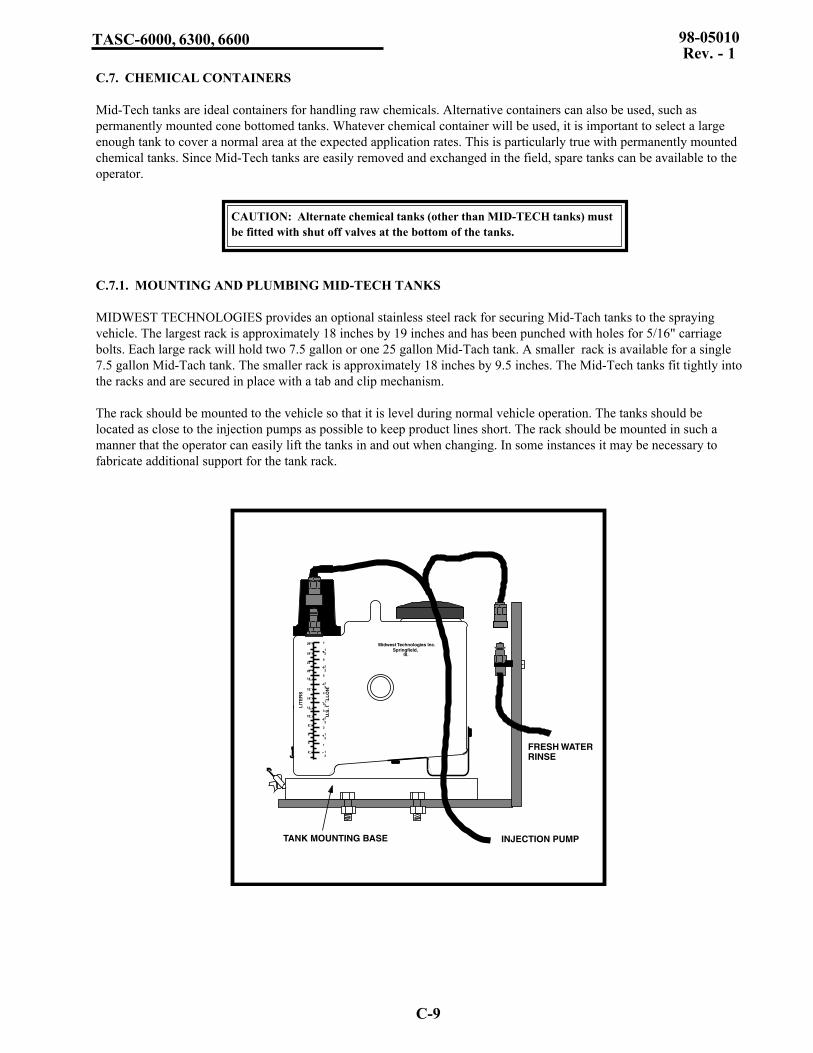
C-9
TASC-6000, 6300, 6600 98-05010Rev. - 1
C.7. CHEMICAL CONTAINERS
Mid-Tech tanks are ideal containers for handling raw chemicals. Alternative containers can also be used, such aspermanently mounted cone bottomed tanks. Whatever chemical container will be used, it is important to select a largeenough tank to cover a normal area at the expected application rates. This is particularly true with permanently mountedchemical tanks. Since Mid-Tech tanks are easily removed and exchanged in the field, spare tanks can be available to theoperator.
C.7.1. MOUNTING AND PLUMBING MID-TECH TANKS
MIDWEST TECHNOLOGIES provides an optional stainless steel rack for securing Mid-Tach tanks to the sprayingvehicle. The largest rack is approximately 18 inches by 19 inches and has been punched with holes for 5/16" carriagebolts. Each large rack will hold two 7.5 gallon or one 25 gallon Mid-Tach tank. A smaller rack is available for a single7.5 gallon Mid-Tach tank. The smaller rack is approximately 18 inches by 9.5 inches. The Mid-Tech tanks fit tightly intothe racks and are secured in place with a tab and clip mechanism.
The rack should be mounted to the vehicle so that it is level during normal vehicle operation. The tanks should belocated as close to the injection pumps as possible to keep product lines short. The rack should be mounted in such amanner that the operator can easily lift the tanks in and out when changing. In some instances it may be necessary tofabricate additional support for the tank rack.
Midwest Technologies Inc.Springfield,
Ill.
LIT
ER
S
U.S
. GA
LL
ON
S
1
12
12
12
12
12
12
12
1
2
2
3
3
4
4
5
5
6
6
7
2
4
6
8
10
12
14
16
18
20
22
24
26
INJECTION PUMP
FRESH WATERRINSE
TANK MOUNTING BASE
CAUTION: Alternate chemical tanks (other than MID-TECH tanks) mustbe fitted with shut off valves at the bottom of the tanks.

C-10
TASC-6000, 6300, 660098-05010Rev. - 1The Mid-Tech tanks comes complete with a chemical resistant, quick disconnect coupler. The product line between thetanks and the injection pump should be at least 1/8 inch larger than the tubing size in the pump, and it must be fitted witha mating coupler (available through MIDWEST TECHNOLOGIES). It is also recommended that a nearby fresh watersource be fitted with a quick disconnect nipple similar to that on the Mid-Tech tank. The injection pump feed line canthen be disconnected from the tank and quickly connected to a fresh water source for flushing the injection system.
C.7.2. GENERAL SUGGESTIONS FOR PLUMBING CHEMICAL TANKS
Line sizes should be at least 1/8" larger than the tubing size for the injection pump. As a general rule keep all plumbingas short as possible, long lines will affect pump capacities and make calibration difficult. Try to keep the bottom of thetank and the injection pump on about the same level, or the tank slightly above the pump. Too great a difference inlevels between the tanks and the pumps (where the pumps are mounted higher on the vehicle than the tanks) can result inreduced maximum pumping rates.
The Peristaltic Injection Pump draws chemical from the chemical container by creating a vacuum at the suction side ofthe pump. In some cases, this vacuum is strong enough to pull air into the suction line through fittings that appear“tight”. Air leaks adversely affect the calibration of the pump, since air bubbles take up space that should be occupied bychemical. This phenomena is most pronounced at low pumping rates and typically shows up as under application in thefield. Ensure that all fittings are sealed with a good quality, liquid pipe dope and are properly tightened, especially thesuction lines. Make sure that hose barbs are clamped tightly.

D-1
TASC-6000, 6300, 6600 98-05010Rev. - 1
APPENDIX-DROADSIDE/HANDGUN
OPERATION

D-2
TASC-6000, 6300, 660098-05010Rev. - 1
D.0. TASC ROADSIDE/HANDGUN OPERATION
TASC roadside spraying operations require a special boom control switchbox or boom interface cable to take advantageof some of the features of the TASC console. Additionally an optional flow switch and cable is needed if a Handgun isto be used.
D.1 Modes of Operation
D.1.1 Normal
In the Normal Mode, the TASC console can control thecarrier and chemical injection pumps in any one of thefollowing manners (See Sect. D.3 for details.):
1. In Auto operation, the carrier and chemical ratesare programmed to give a constant per acre (ha.)application rate regardless of speed. As a result,if you speed up the pressure goes up, and if youslow down the pressure goes down.
2. In Auto "Pressure" operation, the carrier is maintained at a constant pressure regardless of ground speed orbooms On / Off. This results in the carrier rate in gal. / acre (l/ha.) decreasing with higher speeds, and increas-ing with lower speeds. The chemical injection pumps will continue to respond to changes in ground speed orbooms On / Off, thereby maintaining a constant chemical application rate per acre (ha.)
3. In using "Special Purpose Boom Widths" (Alternate Widths “B” or “C”), the chemical injection pumps controlto the programmed “B” or “C” width, ignoring the actual boom widths programmed and turned on. This iscommonly used to spray very steep up and down slopes where the normal programmed boom widths may notaccurately reflect the area actually being sprayed.
D.1.2 Handgun
In the Handgun Mode, the chemical injection pumps start and stop in response to the start of carrier flow sensed by aflow switch. Chemical injection will occur only when the handgun trigger is pulled and flow is established. All boomsmust be turned off for the Handgun mode to operate. The carrier and chemical injection pumps are controlled in any oneof the following manners:
1. The carrier rate is programmed into the TASC console in gallons (liters) per minute and the console controls thecarrier rate with an optional Auto-Range valve. Chemical rates are entered as "ounces per 100 gallons (litersper 1000 liters)" of carrier or as a ratio of the carrier rate, as measured through the flowmeter.
2. The carrier rate is set to 0.0 (Manual Override) and the operator controls the flow through the handgun with theInc / Dec switch on the console, or with the Handgun trigger. The chemical rates are entered as "ounces per100 gallons (liters per 1000 liters)" of carrier or a ratio of the carrier, as measured through the flowmeter.
3. The operator sets the nominal carrier flow rate through the Handgun as a “Test Speed” and the console controlsthe chemical injection pumps at the rate or ratio programmed for them, regardless of the actual flow in thehandgun line.
'B' Width Normal Ground SpeedOverride
'C' Width Handgun Off
Auto
BoomSwitch
ModeSwitch
GroundSpeed
Override
Example 405-0093 Switch Panel

D-3
TASC-6000, 6300, 6600 98-05010Rev. - 1
D.2. HANDGUN MODE OPERATION
D.2.1. HANDGUN MODE, SET-UP FUNCTIONS
To put the TASC in the Handgun mode:
A. Set the switches on the Boom Control Switch Panel as follows:
Boom Width Switch AutoMode Switch HandgunGround Speed Override Switch Off
B. Turn the TASC power "ON" and put the mode selector switch to "SET-UP".
The following programing functions are available in the TASC console:
SPEED: An "Err" message will appear (GSO is not available in the handgun mode).AREA: Area will not accumulate in handgun mode.CHEMICALS, CHEM. APPLIED: This is the pump calibration number for each injection pump (see section 2.8).CHEMICALS, CHEM. RATE: With pump switch in the "ON" position, program the rate as ounces per 100 gallons of
carrier (use the INC/DEC switch to set this rate). With pump switch in the "ALT" position, the display will read as aratio (i.e. 1:100, gal:gal, or oz:oz, chemical:carrier). The rate can be programmed with pump switch in either position.
CHEMICALS, % RATE: Use the INC/DEC switch to set the desired rate change % for chemicals or carrier.CARRIER APPL. RATE: Use the INC/DEC switch to set the desired carrier rate in gallons per minute.CARRIER TOTAL APPLIED: The flow meter calibration number (section 2.6).WIDTH: The message "none" will appear (boom width is not used in the handgun mode).DISTANCE: The distance calibration number (section 2.7).PRIME: The prime volume for each pump (section 2.8.4).TEST SPEED: Using the INC/DEC switch, set a test flow rate in gallons per minute (this rate is required before pumps
can be accurately calibrated).SCAN: An "Err" message will appear (there is no programming in SCAN).
D.2.2. HANDGUN MODE, OPERATE FUNCTIONS
Now put the TASC mode selector switch to "OPERATE". The following programing functions are available in theTASC console:
SPEED: This is a direct reading of ground speed.AREA: Area will not accumulate in the handgun mode.CHEMICALS, CHEM. APPLIED: Accumulated ounces as they are applied, switches to hundredths of gallons after
256 ounces are accumulated.CHEMICALS, CHEM. RATE: This register will indicate the programmed standard rate (oz per 100 gallons) with the
switch "ON". With pump switch in the "ALT" position, the display will read as a ratio (i.e. 1:100, gal:gal, or oz:oz,chemical:carrier).
CHEMICALS, % RATE: Allows changing chemical injection rates a preset percentage (section 3.4.2.1).CARRIER APPL. RATE: Displays target carrier application rate. Actual carrier flow rate in gallons per minute will be
displayed once flow is established. The INC/DEC switch will change the carrier rate by the percentage amountprogrammed in the "Chemicals, % Rate" register (injected rates will not be affected).
CARRIER TOTAL APPLIED: Accumulated gallons applied.WIDTH: "none" (boom widths are not used in the handgun mode.)DISTANCE: Accumulated distance in feet or miles.PRIME: Used for priming the injection pumps (section 3.5).TEST SPEED: The gallons per minute programmed in the "SET-UP" mode is displayed.SCAN: Scans information in the accumulators and registers.

D-4
TASC-6000, 6300, 660098-05010Rev. - 1
D.2.3. HANDGUN MODE, SPECIAL CONSIDERATIONS:
A. Pump Calibrations: The speed of the injection pumps during calibration is determined by the programmed test speed("gallons per minute" or "liters per minute") and the programmed chemical application rate ("ounces per 100 gallons"or liters per 1000 liters") or ratio ("gallons per gallon" or liters per liter). Set these numbers to your typical operatingconditions before doing the pump calibrations.
B. The injection pumps will operate at the speed necessary to apply the correct amount of chemical according to theprogrammed carrier application rate, regardless of small variations in the actual carrier flow rate. (Large variations inthe actual flow rate lasting more than 5 seconds will cause an error shutdown of the sprayer). Thus, chemicals willalways be applied correctly, even if there is variation in the carrier output. (If the carrier rate is set to 0.0, see theManual Override of Flow Control Valve, Section D.2.5.)
C. Booms are not used in the handgun mode. If the TASC senses a boom "ON" condition it will indicate an "Err" andwill stop the injection pumps and close the flow control valve.
D. The initial response of the flow control valve to the selection of the handgun mode is to open fully. Once applicationhas started, the response of the flow control valve to the flow switch "OFF" condition is to "HOLd" the valve in thepartially open condition. The CLOSE valve response is not selectable while operating in the handgun mode.
E. The values programmed into the TASC console while in either the Handgun or Normal mode will remain in consolememory, even when the opposite mode is selected.
F. If operating with a flowmeter, selecting TEST SPEED on the TASC console, while in the "OPERATE" mode, willcause the flow control valve to adjust flow to the test rate selected and the injection pumps to control to the pro-grammed test rate.
D.2.4. HANDGUN MODE, TYPICAL OPERATION:
A. Set the Normal/Handgun switch to "Handgun", the Boom switch to "Auto", and the Ground Speed Override Switch to"OFF".
B. Select "SET-UP" for the TASC console mode selector. Program the TASC console as necessary (See SET-UP Mode,Section D.2.1).
C. Zero the accumulated rates and set the desired carrier flow rate as necessary.
D. Select "OPERATE" with the TASC console mode selector switch. The initial response of the flow control valve is todrive fully open.
E. Turn "ON" the desired chemical injection pumps.
F. Close the valve leading to the spray boom.
G. Be sure the carrier pump is operating. Turn on the handgun. As soon as the flow switch senses flow, the console willbegin to adjust the flow control valve (after a short delay to allow flow to stabilize) to achieve the desired flow ingallons per minute. At the same time the chemical injection pumps will be activated at the speed necessary to applythe desired rates of ounces per hundred gallons, according to the programmed target carrier rate. There is no delay tothe control of the injection pumps. (NOTE: the carrier flow rate is the sum of the carrier and the injected chemicals.)
H. Turn off the handgun. The chemical injection pumps will stop immediately. The flow control valve will hold itsposition so that flow will be immediately available at the proper rate when the handgun is again activated.
I. Set the Normal/Handgun switch to "Normal" and the flow control valve will automatically go closed. Open the valveleading to the spray boom. The TASC console will then be ready for the previously programmed broadcast sprayingoperations.

D-5
TASC-6000, 6300, 6600 98-05010Rev. - 1
D.2.5. HANDGUN MODE, MANUAL VALVE OVERRIDE:
The flow control valve can be set to a manual override condition, if needed. Put the TASC console in "SET-UP" mode,with the display selector on "Carrier, Application Rate". Use the INC/DEC switch to set the application rate to 0.0gallons/minute. When the mode selector is switched back to "OPERATE", the display will show "Flow Contl OFFAuto, Handgun", and the flow control valve is driven fully open.
When in the Manual override condition, and with the display selector in "Carrier, Application Rate", the flow controlvalve responds only to operation of the INC/DEC switch on the console. Flow can be controlled, either by the INC/DECswitch setting, or by feathering the handgun trigger. When flow is established with the handgun valve, the console willdisplay flow as GAL/MIN. Any injection pumps selected "ON" will be controlled to the proper rate per hundred gallons,based on the actual flow rates measured by the flow meter.
OPERATING WITHOUT A FLOWMETER: Manual Override Mode will also allow handgun operation without aflowmeter. Refer to a tip chart to find the pressure required by your handgun tip for the flow rate desired. After puttingthe console into Manual Mode, as described above, use the INC/DEC switch and a pressure gauge to set the desiredpressure. Rotate to "TEST SPEED" and set the desired flow rate in gallons per minute (same flow rate used to selectoperating pressure) with the INC/DEC switch. Operation will be the same as above except that any active injectionpumps will be controlled according to the rate set into the TEST SPEED position.
D.2.6. HANDGUN MODE, ERROR MESSAGES(See also section 8.0 in the TASC Manual)
Error-1: "Error - 1, Pump #" The indicated pump is running at its maximum rate. An Error-1 condition lasting morethan 5 seconds will cause all the injection pumps to stop and the flow control valve to close, stopping all sprayingoperations. Check power connections and programming. Verify that the pump is large enough for the desired flowrate. Once the problem is corrected, Error-1, Pump # is cleared by first selecting Normal and then returning to theHandgun mode on the switch panel.
Error-3: "Error - 3, Pump #" No sensor pulses are being received from the indicated pump. An Error-3 condition lastingmore than 5 seconds will cause all the injection pumps to stop and the flow control valve to close, stopping allspraying operations. Check power, ground and fuses on the pump power cable. Check the programming. Check if thepumps runs before the error condition occurs. Once the problem is corrected, Error-3, Pump # is cleared by firstselecting Normal and then returning to the Handgun mode on the switch panel.
Error-4: "Error - 4, Pump #" The indicated injection pump is running when it should be off. An Error-4 condition willimmediately cause all the injection pumps to stop and the flow control valve to close, stopping all spraying opera-tions. Check for normal operation of the injection pump, the pump driver module may need to be replaced. Once theproblem is corrected, Error-4, Pump # is cleared by first selecting Normal and then returning to the Handgun mode onthe switch panel.
Error-5: "Error -5. Pump F" The carrier flow rate is exceeding the target rate and the flow control valve is not respond-ing to the consoles commands. An Error-5 condition lasting more than 5 seconds will cause all the injection pumps tostop and the flow control valve to close, stopping all spraying operations. Check the fuse and power and ground to theflow control valve. Check for a stuck valve. Once the problem is corrected, Error-5 is cleared by first selectingNormal and then returning to the Handgun mode on the switch panel.

D-6
TASC-6000, 6300, 660098-05010Rev. - 1
D.2.7. HANDGUN MODE, PRINTER OUTPUT SAMPLES
The following two sample printouts show the typical printouts in the HANDGUN MODE. The one on the left showsmetric units and the one on the right shows english units.
D.3. NORMAL MODE OPERATION
D.3.1. NORMAL MODE, AUTOMATIC "PRESSURE" OPERATION
The TASC console can be setup to control to a desired pressure. As boom sections of a balanced sprayer are turned onand off, the control valve will open and close to maintain a flow rate that will give a constant pressure. The controlvalve will adjust according to boom width only. SPEED will not adjust the carrier flow rate.
A. To enter this mode do the following:
MODE SELECTOR SWITCH CARRIER APPL. RATEMODE SWITCH SETUP.Use INC/DEC SWITCH to set rate to 0.0MODE SWITCH OPERATE.
B. Console will read "Flow Contl OFF Auto".
MIDWEST TECHNOLOGIES, INC. TASC- 6300 SPRAY CONTROL
APPLICATION RATES:
CHEM.1 = 39.92 L/100LCHEM.2 = 4.99 L/1000LCHEM.3 = 4.99 L/1000L
CARRIER = . 0 L/MIN
VOLUME APPLIED:CHEM.1 = 38.46 LITERSCHEM.2 = 38.25 LITERSCHEM.3 = 37.87 LITERS
CARRIER = 3038 LITERS
AREA COVERED:
FIELD = 10.04 HATOTAL = 1.8 HA
CHEM. DESCRIPTION
CHEM.1 = ...............................CHEM.2 = ...............................CHEM.3 = ...............................
WEATHER DATA:
TEMP............... %-HUMD...........WND....................DIR. ................
FIELD# ....................................................REF. # ......................................................DATE:......./........./........ TIME: ..... : .......OPER. .....................................................
MIDWEST TECHNOLOGIES, INC. TASC- 6300 SPRAY CONTROL
APPLICATION RATES:
CHEM.1 = 511.1 OZ/100 GALCHEM.2 = 64.0 OZ/100 GALCHEM.3 = 64.0 OZ/100 GAL
CARRIER = . 0 GAL/MIN
VOLUME APPLIED:CHEM.1 = 10.16 GALCHEM.2 = 10.11 GALCHEM.3 = 10.01 GAL
CARRIER = 803 GAL
AREA COVERED:
FIELD = 27.50 ACRESTOTAL = 7.2 ACRES
CHEM. DESCRIPTION
CHEM.1 = ...............................CHEM.2 = ...............................CHEM.3 = ...............................
WEATHER DATA:
TEMP................ %-HUMD...........WND....................DIR...................
FIELD# ....................................................REF. # .......................................................DATE:......./........./........ TIME: ..... : .......OPER. ......................................................

D-7
TASC-6000, 6300, 6600 98-05010Rev. - 1
Monitoring a pressure gauge, use the INC/DEC switch to set the desired pressure. You are now set to operate at apredetermined pressure. Injection pumps will track boom width changes and speed changes to keep chemical rate peracre constant. The console will display flow as GAL/ACRE (LITERS/HECTARE) at speeds above 1 mph. Below 1 mphthe console will display flow as GAL/MIN (LITERS/MIN).
D.3.2. NORMAL MODE, SPECIAL PURPOSE BOOM WIDTHS
For broadcast spraying operations on slopes, separate widths can be programmed into the 'B' or 'C' widths on the TASCconsole. Select the "Normal" mode and 'B' Width or 'C' Width on the Boom Switch Panel. Select the Width displayfunction and the "SET-UP" mode on the TASC console. Enter the desired width in inches.
Now, whenever boom width 'B' or 'C' is selected on the switch panel, the TASC console will automatically adjust itsflow rate for the programmed width, regardless of the position of the individual boom valves

D-8
TASC
-6000, 6300, 660098-05010R
ev. - 1
+
Vehicle Battery(12 Volts)
TASC-6300 CONSOLE
Pump ControlCables
Ground Speed Sensor120-0000-KIT
Chemical Injection Pumps
Pump PowerCables
RoadsideBoom Interface
405-0092
1
9
120-xxxx
Printer Module(Optional)
Flowmeter Interface Cable
405-0044
Flow Control Valve
879-xxxx
Flow Control Cable
( 404-0022)
Fuse,(10 amp)
Power Cable
(401-0010)
Fuse,(5 amp)RedBlack
Battery Cable(45-05037)
Fuse,(15 amp)
Neg.
Pos.
Connect Direct to BATTERY
Data Logger(Optional)
Data Link(Optional)
405-0069-96V
BOOMSHandgun/9 Boom
Sense Switchbox405-0093
Flowsensor120-0004 or
120-0005
Flow Sensor Cable402-0009
To existing Boom Switches
Battery Cable(401-0011)
Valve Driver Cable
( 405-0143)
TASC-6600 CONSOLE
or
Roadside Wiring Diagram
CHEMICAL APPLICATORS
1 2 3
ON
OFF
Alt.-Rate TASC-6300
TOTAL APPLICATIONSPRAYER CONTROL
%Rate
DISPLAY SELECTOR
Speed
Area Width
Distance
Chem. Applied
Test Speed
Prime
Total Applied
Chem. Rate Appl. RateCHEMICALS CARRIER
OFF SET- UP DEC.
ON OPERATE INC.
1 2 3 4 5 6 7 8 9BOOMS
Scan
MID-TECH
MIDWEST TECHNOLOGIES, INC.
.
-Ac
Flow
RATE
Gal./
®
Flow Meter
MIDWEST TECHNOLOGIES INC.2733 East Ash Street
Springfield IL - (217) 753-8424www.mid-tech.com
'B' Width Normal Ground SpeedOverride
'C' Width Handgun Off
Auto
D4 - R
OA
DSID
E SYSTEM
DIA
GR
AM

D-9
TASC
-6000, 6300, 660098-05010R
ev. - 1
+
Vehicle Battery(12 Volts)
TASC-6300 CONSOLE
Pump ControlCables
Ground Speed Sensor120-0000-KIT
Chemical Injection Pumps
Pump PowerCables
(120-xxxx)
Printer Module(Optional)
Flowmeter Interface Cable(405-0044)
Flow Control Valve879-xxxx
Flow Control Cable(404-0022)
Fuse,(10 amp)
Power Cable(401-0010)
Fuse,(5 amp)RedBlack
Battery Cable(45-05037)
Fuse,(15 amp)
Neg.
Pos.
Connect Direct to BATTERY
Data Link(Optional)
405-0069-96V
Battery Cable(401-0011)
Valve Driver Cable(405-0143)
TASC-6600 CONSOLEor
Roadside Wiring with
Mid-Tech Switchbox
CHEMICAL APPLICATORS
1 2 3
ON
OFF
Alt.-Rate TASC-6300
TOTAL APPLICATIONSPRAYER CONTROL
%Rate
DISPLAY SELECTOR
Speed
Area Width
Distance
Chem. Applied
Test Speed
Prime
Total Applied
Chem. Rate Appl. RateCHEMICALS CARRIER
OFF SET- UP DEC.
ON OPERATE INC.
1 2 3 4 5 6 7 8 9BOOMS
Scan
MID-TECH
MIDWEST TECHNOLOGIES, INC.
.
-Ac
Flow
RATE
Gal./
®
Flow Meter
Flowsensor120-0004 or
120-0005
1
9
BOOMS
FrameGround
(404-0037)9 Boom Sense
Cable Caution
Connect To
+12v Only
Battery
(404-0009)Extension Cable
MIDWEST TECHNOLOGIES INC.2733 East Ash Street
Springfield IL - (217) 753-8424www.mid-tech.com
SPRAY MODE
NORMAL - HANDGUN
(405-0088)Boom Control
Switchbox
BOOMS
MASTEROFF - ON
OFF
GROUND SPEEDOVERRIDE
WIDTHAUTO
MIDWEST TECHNOLOGIES, INC.
SPRAY MODENORMAL - HANDGUN
ON "B" "C"
D5 - R
OA
DSID
E SYSTEM
DIA
GR
AM
W/M
ID-TEC
H SW
ITCH
BOX

D-10
TASC-6000, 6300, 660098-05010Rev. - 1
This page purposely left blank