mid-air collision avoidance and flight operations …
TRANSCRIPT

MID-AIR COLLISION AVOIDANCE AND FLIGHT OPERATIONS
AT LITTLE ROCK AIR FORCE BASE
AND CAMP ROBINSON
LITTLE ROCK AIR FORCE BASE MID-AIR COLLISION AVOIDANCE PROGRAM
REVISED: 9 April 2015
*** WARNING *** THE ENCLOSED MATERIAL IS FOR INFORMATIONAL PURPOSES ONLY!
IT IS NOT TO BE USED IN FLIGHT PLANNING OTHER THAN AS A SOURCE TO ENHANCE MID-AIR COLLISION AVOIDANCE. ALL INFORMATION, DESCRIPTIONS, ROUTES, AND PROCEDURES ARE
SUBJECT TO CHANGE WITHOUT NOTICE. *** WARNING ***
1
TABLE OF CONTENTS
INTRODUCTION .................................................................................. 3 KLRF AIRPORT DIAGRAM ................................................................ 4 LITTLE ROCK AFB INFORMATION ................................................. 5 CAMP ROBINSON INFORMATION ................................................... 6 LOCAL AIRCRAFT, DESCRIPTION, AND MISSION ...................... 7 TRANSIENT AIRCRAFT.................................................................... 11 LITTLE ROCK AFB CLASS D AIRSPACE ...................................... 12 DEPARTURES AND ARRIVALS ...................................................... 13 MILITARY TRAINING ROUTES (MTRs) ........................................ 14 GEOMETRY OF A MID-AIR COLLISION ....................................... 15 MID-AIR COLLISION AVOIDANCE FUNDAMENTALS .............. 17 NEAR MID-AIR COLLISION REPORTING ..................................... 18
2

INTRODUCTION Mid-Air Collision Avoidance (MACA) is a very important topic within military and civilian aviation. The United States Air Force is committed to working with the civilian aviation community to keep our shared airspace safe. As part of our continuing public information program, the 19th Airlift Wing (19 AW) produced this pamphlet in cooperation with the 314th Airlift Wing (314 AW) the 189th Airlift Wing (189 AW), the 913th Airlift Group (913 AG), and the 77th Theater Aviation Brigade to educate our civilian counterparts on the intensive military training air operations around Little Rock AFB. Our goal is to heighten awareness and reduce the potential for mid-air collisions. Since military missions are somewhat structured, there are certain places where you can expect to see us conducting our daily operations. Although the areas discussed are not all inclusive, the following information should give you a good idea of how and where we operate. Included within this pamphlet is information on locally-based and transient aircraft, training routes, traffic patterns, and arrival and departure routes. The 19 AW Safety Office is the office of primary responsibility (OPR) for the development, publishing, and maintenance of the Little Rock AFB MACA program pamphlet. If you have any questions concerning any information within this pamphlet, or you would like a copy, please contact the 19 AW Flight Safety Office at (501) 987-5772. An electronic copy of this document is also available on the Little Rock AFB Homepage at http://www.littlerock.af.mil. We hope this guide proves useful in avoiding areas of congestion, determining the best routes of flight, and minimizing potential conflicts. We solicit your help in making the skies over Arkansas a safer place to fly. Thank you for your interest and vigilance!
3

KLRF AIRPORT DIAGRAM
4

LITTLE ROCK AFB INFORMATION Operating Hours: 7 days a week - 24 hrs a day. Extensive NVG (Night Vision
Goggle) operations during periods of darkness. Exceptions by NOTAM.
Location: Coordinates 34°55.01’ N 92° 08.79’ W Navaids: Jacksonville (LRF) TACAN (CH 29)
ILS 25 (109.9), Toneyville (TYV) NDB (290)
Instrument Approaches: ILS, TACAN, NDB, ARA - Runway 25 TACAN – Runway 07
(Runway 25 is the Primary Runway) Airfield Lighting: Rotating Beacon (1 Green, 2 White) Runway Lighting: Standard HIRL for 07/25. MIRL for assault strip. Threshold
Lights, Distance Remaining Markers on main runway. Approach Lighting: Cat I ALSF with sequenced flashing lights for 07/25 Frequencies: Air Traffic Control Tower……………….……..….120.6/269.075
Approach Control……………………….……….....119.5/306.2 ATIS…………………………………………….....119.175/251.1 Blackjack Drop Zone……………………………….139.6/342.4 All-American Landing Zone/Drop Zone……............141.8/342.3
Phone Numbers: 19th AW Airspace Manager………..………….....(501) 987-5159
19th AW Flight Safety Office……………………(501) 987-5772 Airfield Operations Flight Commander…………..(501) 987-3104 Little Rock Appr Control…Primary……………...(501) 379-2905
Little Rock AFB Tower………..……………..…..(501) 987-3139 Airfield Management Operations.…………..…....(501) 987-6123 Airfield Manager…………………………..…..…(501) 987-3103 Lockheed Martin FSS (Jonesboro)...…………......(800) 992-7433
Elevation: 311 ft. / 94.8 m (surveyed) Variation: 01E (2010) From city: 1 mile SE of JACKSONVILLE, AR Time zone: UTC -6 (UTC -5 during Daylight Saving Time)
5
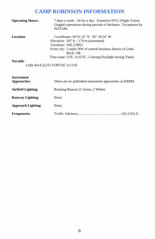
CAMP ROBINSON INFORMATION Operating Hours: 7 days a week - 24 hrs a day. Extensive NVG (Night Vision
Goggle) operations during periods of darkness. Exceptions by NOTAM.
Location: Coordinates 34°51.32’ N 92° 18.54’ W Navaids: Little Rock (LIT) VORTAC (113.9)
Instrument Approaches: There are no published instrument approaches at KRBM. Airfield Lighting: Rotating Beacon (1 Green, 2 White) Runway Lighting: None Approach Lighting: None Frequencies: Traffic Advisory...……………………….…….126.2/241.0
Elevation: 587 ft. / 179 m (estimated) Variation: 04E (1985) From city: 5 miles NW of central business district of Little
Rock, AR Time zone: UTC -6 (UTC -5 during Daylight Saving Time)
6

LOCAL AIRCRAFT, DESCRIPTION, AND MISSION C-130
The C-130H and the newest version, the C-130J are flown at Little Rock AFB. The C-130, produced by the Lockheed Martin Corporation, is a long range, multi-purpose cargo aircraft that provides tactical airlift operations on a global basis. Depending on the model, it is capable of carrying 92 or 128 ground troops, 64 or 92 paratroopers, and 73 or 97 litters for aeromedical evacuation, and can also be configured to carry rolling or palletized cargo. This cargo can then be off loaded on the ground or airdropped, as mission requirements dictate. The C-130 is also capable of operating on short runways and dirt airstrips.
Performance/Specifications
H Model J Model (-30 Stretch)
MAX LANDING / TAKEOFF WEIGHT 155,000 LBS 164,000 LBS
CRUISE SPEED 280-300 KTAS 320 KTAS
LOW-LEVEL AIRSPEED 200-230 KIAS 210-250 KIAS
APPROACH SPEEDS 110-160 KIAS 105-160 KIAS
DEPARTURE SPEEDS 160-180 KIAS 160-180 KIAS
MIN RUNWAY REQ'D (for training) 3,000 ft 3,000 ft
WING SPAN 132 ft. 7 in. 132 ft. 7 in.
LENGTH 99 ft. 6 in. 112 ft. 9 in.
HEIGHT 38 ft. 6 in. 38 ft. 9 in.
C-130J Hercules
C-130H Hercules
J-Model Visual Differences: - Six Bladed Propellers - No Wing Tanks - De-Ice Boot on Tail - 15 ft. Longer (Stretch model)
7

UH-60 and UH-72
Both the UH-60 Blackhawk and UH-72 Lakota are flown at Camp Robinson. The UH-60 Blackhawk, produced by Sikorsky Aircraft, is a twin engine, medium-lift utility helicopter. Although it comes in many special purpose variants, the UH-60 performs a wide array of missions, including transport of troops, air assault operations, and medical evacuation. The UH-72 Lakota, produced by Eurocopter, is a twin engine light utility helicopter designed for general support, medical evacuation, and personnel recovery..
Performance/Specifications
UH-60 Blackhawk UH-72 Lakota
MAX LANDING / TAKEOFF WEIGHT 22,000 LBS 7,900 LBS
CRUISE SPEED 150 KTAS 133 KTAS
LOW-LEVEL AIRSPEED 150 KIAS 120 KIAS
APPROACH SPEEDS 10-110 KIAS 10-100 KIAS
DEPARTURE SPEEDS 10-150 KIAS 10-130 KIAS
MIN RUNWAY REQ'D (for training) 0 ft 0 ft
ROTOR DIAMETER 53 ft. 8 in. 36 ft. 1 in.
LENGTH 64 ft. 10 in. 42 ft. 7 in.
HEIGHT 16 ft. 10 in. 11 ft. 9 in.
UH-72 Lakota
UH-60 Blackhawk
8
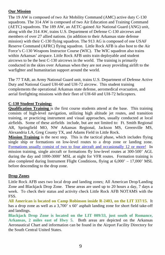
Our Mission The 19 AW is composed of two Air Mobility Command (AMC) active duty C-130 squadrons. The 314 AW is composed of two Air Education and Training Command (AETC) squadrons. The 189 AW, an AETC-gained Air National Guard (ANG) unit, along with the 314 AW, trains U.S. Department of Defense C-130 aircrews and members of over 27 allied nations. (in addition to their Arkansas state defense mission) with their C-130 flying squadron. The 913 AG is composed of one USAF Reserve Command (AFRC) flying squadron. Little Rock AFB is also host to the Air Force’s C-130 Weapons Instructor Course (WIC). The WIC squadron also trains within Arkansas’ airspace. Little Rock AFB units train deployable and student aircrews to be the best C-130 aircrews in the world. The training is primarily conducted in the skies over Arkansas when they are not away providing airlift to the warfighter and humanitarian support around the world. The 77 TAB, an Army National Guard unit, trains U.S. Department of Defense Active Duty and National Guard UH-60 and UH-72 aircrew. This student training complements the operational Arkansas state defense, aeromedical evacuation, and aerial firefighting missions with their fleet of UH-60 and UH-72 helicopters. C-130 Student Training: Qualification Training is the first course students attend at the base. This training consists of high-level navigation, utilizing high altitude jet routes, and transition training, or practicing instrument and visual approaches, usually conducted at local airfields. Some of these airfields include, but are not limited to: Ft. Smith Regional AR, Springfield MO, NW Arkansas Regional, Jackson MS, Greenville MS, Alexandria LA, Greg County TX, and Adams Field in Little Rock. Mission Training is the next step. This is the tactical phase, which includes flying single ship or formations on low-level routes to a drop zone or landing zone. Formations usually consist of two to four aircraft and occasionally 12 or more! In mission training, single aircraft or formations fly low-level routes at 300-500’ AGL during the day and 1000-3000’ MSL at night for VFR routes. Formation training is also completed during Instrument Flight Conditions, flying at 6,000’ – 17,000’ MSL before descending to the drop zone.
Drop Zones Little Rock AFB uses two local drop and landing zones; All American Drop/Landing Zone and Blackjack Drop Zone. These areas are used up to 20 hours a day, 7 days a week. To check their status and activity check Little Rock AFB NOTAMS with the FSS. All American is located on Camp Robinson inside R-2403, on the LIT 337/15. It has a drop zone as well as a 3,700’ x 60’ asphalt landing zone for short field take-off and landings. Blackjack Drop Zone is located on the LIT 009/33, just south of Romance, Arkansas, 2 miles east of Hwy 5. Both areas are depicted on the Arkansas Aeronautical Chart and information can be found in the Airport Facility Directory for the South Central United States.
9

Most airdrops occur at 300’-1200’ AGL, although we have some being conducted at 7,000’ MSL. The most common airdropped items are fifteen pound sandbags, 1,000-lb boxes, and 3,000-lb simulated heavy equipment pallets. However, actual personnel and equipment are also dropped. NOTE: Some aircraft and crews are certified to drop in IFR conditions, in or above the clouds, without visual reference with the ground. We issue NOTAMS prior to any IFR airdrops, so be sure to check with FSS for the latest information. Tactical missions are based on crews successfully avoiding hostile threats as they fly their low-level route to the Initial Point (IP), the point immediately prior to the objective. The run-in from the IP to the objective for an airdrop or assault landing is most critical to the mission. This period is the busiest part of the entire mission for each crewmember. The crew is focused on stabilizing the aircraft on drop/landing heading, altitude, and airspeed, evaluating drop winds, talking to drop zone controllers, and visually acquiring the objective. Heavy tasking during this critical phase of flight greatly increases the possibility that crews may not see small aircraft transiting the area. In the interest of air safety, we ask all pilots to exercise extreme caution when flying near All American or Blackjack Drop Zones, especially on each drop zones’ east and west approach corridor.
10

TRANSIENT AIRCRAFT FREQUENTLY SEEN AT LITTLE ROCK AFB
T-1A JAYHAWK
T-6 TEXAN II
A-10 THUNDERBOLT II
T-38C TALON
T-44A PEGASUS
KC-10 EXTENDER
F-15 EAGLE
F-18 HORNET
F-16 FALCON
C-5 GALAXY
C-17 GLOBEMASTER III
KC-135 STRATOTANKER
11

LITTLE ROCK AFB CLASS D AIRSPACE
1. Little Rock Class D Airspace: Airspace from the surface up to and including 2800’ MSL within a 5.6 NM radius of Little Rock AFB (published as 34 55 01 N & 92 08 79 W). Unless otherwise authorized by Air Traffic Control, an operable two-way radio is required. Two-way radio communication must be established with Little Rock AFB Tower, on 120.6, prior to entry and thereafter, maintaining communications while in the Class D airspace. Radio contact should be initiated far enough from the Class D airspace boundary to preclude entering Class D airspace before two-way radio communications are established. Aircraft following Hwy 67/167 will fly through the Class D airspace and cross the base's final approach course. Aircraft in the pattern at North Little Rock must be aware that the airport is 2 miles outside of the Class D. 2. Surrounding Airspace: The airspace within a 20 NM semi-circle north of Little Rock AFB from 500 AGL to 3000 MSL is used extensively and normally has high concentrations of aircraft. THIS AIRSPACE HAS GREATER POTENTIAL FOR MID-AIR COLLISION WITH LRAFB C-130S THAN ANY OTHER AREA IN THE STATE! This airspace includes the radar pattern, departure and arrival routing for VFR / IFR low-level routes, two drop zones, and local civilian fields. Two-way radio communication with Little Rock Approach Control in this area is advised to ensure safe aircraft separation. (Please see pg. 10 for a depiction of the LRAFB local airspace and the appropriate frequency to use.) Airfields in close proximity to the base and the drop zones are: Conway, Searcy, North Little Rock, and various private fields. Pilots are urged to review with their students the importance of situational awareness and “see and avoid” techniques.
W/in 5.6 NM Contact Tower 120.6
AADZ/LZ
12
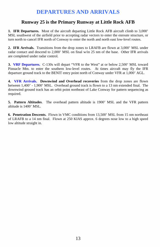
DEPARTURES AND ARRIVALS
Runway 25 is the Primary Runway at Little Rock AFB 1. IFR Departures. Most of the aircraft departing Little Rock AFB aircraft climb to 3,000’ MSL southwest of the airfield prior to accepting radar vectors to enter the enroute structure, or turn north to cancel IFR north of Conway to enter the north and north east low-level routes. 2. IFR Arrivals. Transitions from the drop zones to LRAFB are flown at 3,000’ MSL under radar contact and descend to 2,000’ MSL on final w/in 25 nm of the base. Other IFR arrivals are completed under radar control. 3. VRF Departures. C-130s will depart “VFR to the West” at or below 2,500’ MSL toward Pinnacle Mtn. to enter the southern low-level routes. At times aircraft may fly the IFR departure ground track to the BENIT entry point north of Conway under VFR at 1,000’ AGL. 4. VFR Arrivals. Downwind and Overhead recoveries from the drop zones are flown between 1,400’ - 1,900’ MSL. Overhead ground track is flown to a 13 nm extended final. The downwind ground track has an orbit point northeast of Lake Conway for pattern sequencing as required. 5. Pattern Altitudes. The overhead pattern altitude is 1900’ MSL and the VFR pattern altitude is 1400’ MSL. 6. Penetration Descents. Flown in VMC conditions from 13,500’ MSL from 15 nm northeast of LRAFB to a 14 nm final. Flown at 250 KIAS approx. 6 degrees nose low to a high speed low altitude straight in.
13
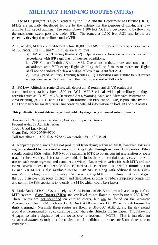
MILITARY TRAINING ROUTES (MTRs) 1. The MTR program is a joint venture by the FAA and the Department of Defense (DOD). MTRs are mutually developed for use by the military for the purpose of conducting low-altitude, high-speed training. The routes above 1,500 feet AGL are developed to be flown, to the maximum extent possible, under IFR. The routes at 1,500 feet AGL and below are generally developed to be flown under VFR. 2. Generally, MTRs are established below 10,000 feet MSL for operations at speeds in excess of 250 knots. The IFR and VFR routes are as follows:
a) IFR Military Training Routes (IR). Operations on these routes are conducted in accordance with IFR regardless of weather conditions. b) VFR Military Training Routes (VR). Operations on these routes are conducted in accordance with VFR except flight visibility shall be 5 miles or more; and flights shall not be conducted below a ceiling of less than 3,000 feet AGL. c) Slow Speed Military Training Routes (SR). Operations are similar to VR routes except weather is 1500 and 3 and the maximum speed is 250 knots.
3. IFR Low Altitude Enroute Charts will depict all IR routes and all VR routes that accommodate operations above 1,500 feet AGL. VFR Sectionals will depict military training activities such as IR, VR, MOA, Restricted Area, Warning Area, and Alert Area information. Area Planning (AP/1B) Chart (DOD Flight Information Publication-FLIP) is published by the DOD primarily for military users and contains detailed information on both IR and VR routes. This publication is available to the general public by single copy or annual subscription from: Aeronautical Navigation Products (AeroNav) Logistics Group Federal Aviation Administration 10201 Good Luck Road Glenn Dale, MD 20769−9700 Toll free phone: 1−800−638−8972 / Commercial: 301−436−8301 4. Nonparticipating aircraft are not prohibited from flying within an MTR; however, extreme vigilance should be exercised when conducting flight through or near these routes. Pilots should contact FSSs within 100 NM of a particular MTR to obtain current information or route usage in their vicinity. Information available includes times of scheduled activity, altitudes in use on each route segment, and actual route width. Route width varies for each MTR and can extend several miles on either side of the charted MTR centerline. Route width information for IR and VR MTRs is also available in the FLIP AP/1B along with additional MTR (slow routes/air refueling routes) information. When requesting MTR information, pilots should give the FSS their position, route of flight, and destination in order to reduce frequency congestion and permit the FSS specialist to identify the MTR which could be a factor. 5. Little Rock AFB C-130s routinely use Slow Routes or SR Routes, which are not part of the MTR system. Slow Routes (SR's) are low-level routes flown at speeds under 250 KIAS. These routes are not identified on enroute charts, but can be found on the Arkansas Aeronautical Chart. C-130s from Little Rock AFB use over 15 SR's within Arkansas for daily training. Normally these routes are flown at 300-500’ AGL during the day except around environmental or noise sensitive areas where the altitudes are increased. The following 4 pages contain a depiction of the routes over a sectional. NOTE: This is intended for situational awareness only, not for navigation. In addition, the routes are 5 nm either side of centerline.
14
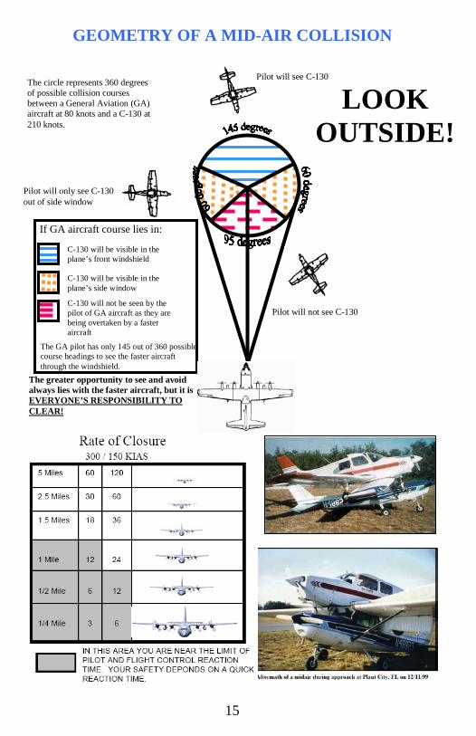
Pilot will see C-130
Pilot will not see C-130
Pilot will only see C-130 out of side window
The greater opportunity to see and avoid always lies with the faster aircraft, but it is EVERYONE’S RESPONSIBILITY TO CLEAR!
The circle represents 360 degrees of possible collision courses between a General Aviation (GA) aircraft at 80 knots and a C-130 at 210 knots.
If GA aircraft course lies in: C-130 will be visible in the plane’s front windshield C-130 will be visible in the plane’s side window C-130 will not be seen by the pilot of GA aircraft as they are being overtaken by a faster aircraft
The GA pilot has only 145 out of 360 possible course headings to see the faster aircraft through the windshield.
LOOK OUTSIDE!
GEOMETRY OF A MID-AIR COLLISION
15
16

MID-AIR COLLISION AVOIDANCE
FUNDAMENTALS 1. Whether flying under IFR or VFR, practice the “see and avoid” concept at all times. 2. Under IFR control, do not count on ATC to keep you away from other aircraft. IFR separation only exists between you and other IFR aircraft. There may be VFR aircraft operating in your environment that ATC is unaware of. 3. Be familiar with the limitations of your eyes and use proper scanning techniques. Remember, if another aircraft appears to have relative motion, but is increasing in size, then it is likely to be on a collision course with you. 4. Execute appropriate clearing procedures before all climbs, descents, turns, training maneuvers or aerobatics. 5. Be aware of the type airspace in which you intend to operate and comply with the applicable rules. 6. If your aircraft is equipped with a transponder, turn it on and adjust it to reply on both Mode 3/A and Mode C (if installed). Paragraph 4-18 in the Airman’s Information Manual states: “IN ALL CASES, WHETHER VFR OR IFR, THE TRANSPONDER SHOULD BE OPERATING WHILE AIRBORNE UNLESS OTHERWISE REQUESTED BY ATC.” 7. Adhere to the necessary communications requirements. 8. Traffic advisories should be requested and used when available to assist the pilot’s own visual scanning; advisories in no way lessen the pilot’s obligation to the “see and avoid” concept. 9. If unable to initiate radio contact for traffic information, at least monitor the appropriate frequency. 10. Make frequent position reports along your routes and broadcast your position at uncontrolled airports. 11. Make your aircraft as visible as possible-- turn on exterior lights and landing lights below 10,000 MSL when operating within 10 miles of any airport, in conditions of reduced visibility, where any bird activity is expected or when under special VFR clearance. 12. Know where high-density traffic areas are. 13. When flying at night, don’t use white interior lights unless absolutely necessary. It takes your eyes a while to adjust to low light levels. 14. Fly VFR hemispheric altitudes.
17

NEAR MID-AIR COLLISION REPORTING 1. Purpose and Data Uses. The primary purpose of the Near Mid-Air Collision (NMAC) Reporting Program is to provide information for use in enhancing the safety and efficiency of the National Airspace System. Data obtained from NMAC reports are used by the FAA to improve the quality of FAA services to users and to develop programs, policies, and procedures aimed at the reduction of NMAC occurrences. All NMAC reports are thoroughly investigated by Flight Standards Facilities in coordination with Air Traffic Facilities. Data from these investigations are transmitted to FAA Headquarters in Washington, DC, where they are compiled and analyzed, and where safety programs and recommendations are developed. 2. Definition. An NMAC is defined as an incident associated with an aircraft in which a possibility of collision exists as a result of proximity of less than 500 feet to another aircraft, or a report is received from a pilot or a flight crew member stating a collision hazard existed between two or more aircraft. 3. Reporting Responsibility. It is the responsibility of the pilot and/or flight crew to determine whether an NMAC did actually occur and, if so, to initiate a NMAC report. Be specific, as ATC will not interpret a casual remark to mean that a NMAC is being reported. The pilot should state: "I wish to report a near mid-air collision." 4. Where to File Reports. Pilots and/or flight crew members involved in NMAC occurrences are urged to report each incident immediately: a) By radio or telephone to the nearest FAA ATC facility or FSS or, b) In writing to the nearest Flight Standards District Office (FSDO). 5. Items to be Reported. a) Date and time (UTC) of incident. b) Location of incident and altitude.
c) Identification and type of reporting aircraft, aircrew destination, name and home base of pilot.
d) Identification and type of other aircraft, aircrew destination, name and home base of pilot.
e) Type of flight plans; station altimeter setting used. f) Detailed weather conditions at altitude or flight level. g) Approximate courses of both aircraft: indicate if one or both aircraft were climbing
or descending. h) Reported separation in distance at first sighting, proximity at closest point
horizontally and vertically, and length of time in sight prior to evasive action. i) Degree of evasive action taken, if any (from both aircraft, if possible). j) Injuries, if any.
18
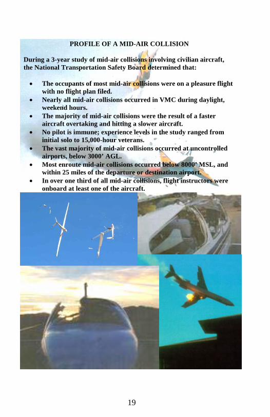
PROFILE OF A MID-AIR COLLISION
During a 3-year study of mid-air collisions involving civilian aircraft, the National Transportation Safety Board determined that: • The occupants of most mid-air collisions were on a pleasure flight
with no flight plan filed. • Nearly all mid-air collisions occurred in VMC during daylight,
weekend hours. • The majority of mid-air collisions were the result of a faster
aircraft overtaking and hitting a slower aircraft. • No pilot is immune; experience levels in the study ranged from
initial solo to 15,000-hour veterans. • The vast majority of mid-air collisions occurred at uncontrolled
airports, below 3000’ AGL. • Most enroute mid-air collisions occurred below 8000’ MSL, and
within 25 miles of the departure or destination airport. • In over one third of all mid-air collisions, flight instructors were
onboard at least one of the aircraft.
19