microwave dli microwave catalog products · dli s microwave catalog products integrate two ... smd...
TRANSCRIPT
www.knowlesprecisiondevices.com
© Copyright Knowles Precision Devices, 2019 - design: [email protected]
Asian Sales OfficeO: +86 512 62588258F: +86 512 [email protected]
European Sales OfficeO: +44 1603 723300F: +44 1603 [email protected]
North American Sales OfficeO: +1 661 295 5920F: +1 661 295 5928O: +1 315 655 8710F: +1 315 655 [email protected]
DLI Microwave Catalog Products
Typical Applications
l Microwave Radarl Test Equipmentl Switch Filter Banksl Satellite and Radio Communicationsl Synthesizer and filter banksl 5G Base Stations
RoHS Compliance StatementDLI is a leading supplier to the electronic components market and is fully committed to offering products supporting Restriction of Hazardous Substances (RoHS) directives. All of our Dielectric formulations are RoHS compliant and we offer a broad range of capacitors with RoHS compliant terminations. DLI complies with the requirements of the individual customer and will maintain product offerings that meet the demands of our industry.
Quality and Environmental PolicyDLI’s reputation for quality and environmental responsibility is based on a commitment not only to meet our customers’ requirements, but to exceed their expectations. The entire organization, beginning with top management, strives to achieve excellence in designing, manufacturing and delivering High Q Capacitors and proprietary thin film components for niche high frequency applications, while maintaining safe and healthy working conditions. Furthermore, DLI commits to achieve these goals in an environmentally responsible manner through our commitment to comply with environmental regulations and pollution prevention initiatives. DLI strives to continually improve the effectiveness of our Quality and Environmental Management System through the establishment and monitoring of objectives and targets.
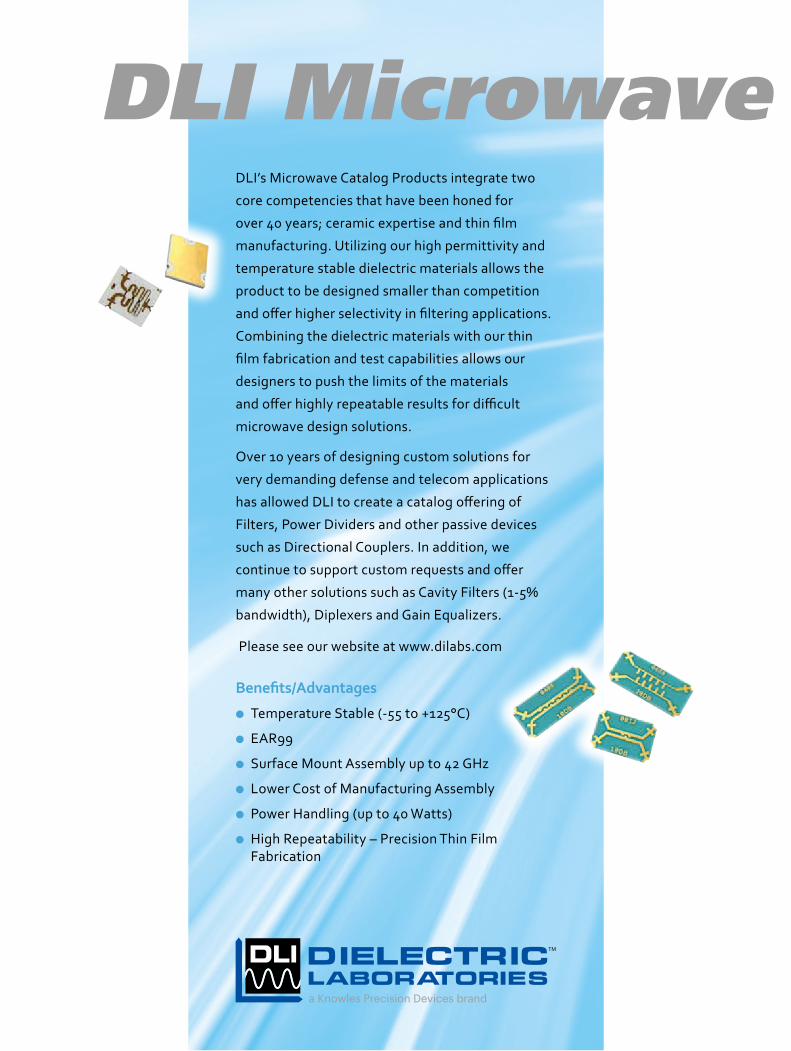
DLI’s Microwave Catalog Products integrate two
core competencies that have been honed for
over 40 years; ceramic expertise and thin film
manufacturing. Utilizing our high permittivity and
temperature stable dielectric materials allows the
product to be designed smaller than competition
and offer higher selectivity in filtering applications.
Combining the dielectric materials with our thin
film fabrication and test capabilities allows our
designers to push the limits of the materials
and offer highly repeatable results for difficult
microwave design solutions.
Over 10 years of designing custom solutions for
very demanding defense and telecom applications
has allowed DLI to create a catalog offering of
Filters, Power Dividers and other passive devices
such as Directional Couplers. In addition, we
continue to support custom requests and offer
many other solutions such as Cavity Filters (1-5%
bandwidth), Diplexers and Gain Equalizers.
Please see our website at www.dilabs.com
Benefits/Advantages
l Temperature Stable (-55 to +125°C)
l EAR99
l Surface Mount Assembly up to 42 GHz
l Lower Cost of Manufacturing Assembly
l Power Handling (up to 40 Watts)
l High Repeatability – Precision Thin Film Fabrication
a Knowles Precision Devices brand
TM
Cert
ified
Sys
tem TM
ISO 14001
Cert
ified
Sys
tem TM
ISO 9001:2000& AS9100B
DLI Microwave Catalog Products
Typical Applications
l Microwave Radarl Test Equipmentl Switch Filter Banksl Satellite and Radio Communicationsl Synthesizer and filter banksl 5G Base Stations
RoHS Compliance StatementDLI is a leading supplier to the electronic components market and is fully committed to offering products supporting Restriction of Hazardous Substances (RoHS) directives. All of our Dielectric formulations are RoHS compliant and we offer a broad range of capacitors with RoHS compliant terminations. DLI complies with the requirements of the individual customer and will maintain product offerings that meet the demands of our industry.
Quality and Environmental PolicyDLI’s reputation for quality and environmental responsibility is based on a commitment not only to meet our customers’ requirements, but to exceed their expectations. The entire organization, beginning with top management, strives to achieve excellence in designing, manufacturing and delivering High Q Capacitors and proprietary thin film components for niche high frequency applications, while maintaining safe and healthy working conditions. Furthermore, DLI commits to achieve these goals in an environmentally responsible manner through our commitment to comply with environmental regulations and pollution prevention initiatives. DLI strives to continually improve the effectiveness of our Quality and Environmental Management System through the establishment and monitoring of objectives and targets.
DLI’s Microwave Catalog Products integrate two
core competencies that have been honed for
over 40 years; ceramic expertise and thin film
manufacturing. Utilizing our high permittivity and
temperature stable dielectric materials allows the
product to be designed smaller than competition
and offer higher selectivity in filtering applications.
Combining the dielectric materials with our thin
film fabrication and test capabilities allows our
designers to push the limits of the materials
and offer highly repeatable results for difficult
microwave design solutions.
Over 10 years of designing custom solutions for
very demanding defense and telecom applications
has allowed DLI to create a catalog offering of
Filters, Power Dividers and other passive devices
such as Directional Couplers. In addition, we
continue to support custom requests and offer
many other solutions such as Cavity Filters (1-5%
bandwidth), Diplexers and Gain Equalizers.
Please see our website at www.dilabs.com
Benefits/Advantages
l Temperature Stable (-55 to +125°C)
l EAR99
l Surface Mount Assembly up to 42 GHz
l Lower Cost of Manufacturing Assembly
l Power Handling (up to 40 Watts)
l High Repeatability – Precision Thin Film Fabrication
a Knowles Precision Devices brand
TM
Cert
ified
Sys
tem TM
ISO 14001
Cert
ified
Sys
tem TM
ISO 9001:2000& AS9100B
10766/Microwave/19/v3
MicrowaveProducts
www.knowlesprecisiondevices.com
© Copyright Knowles Precision Devices, 2019 - design: [email protected]
Asian Sales OfficeO: +86 512 62588258F: +86 512 [email protected]
European Sales OfficeO: +44 1603 723300F: +44 1603 [email protected]
North American Sales OfficeO: +1 661 295 5920F: +1 661 295 5928O: +1 315 655 8710F: +1 315 655 [email protected]
DLI Microwave Catalog Products
Typical Applications
l Microwave Radarl Test Equipmentl Switch Filter Banksl Satellite and Radio Communicationsl Synthesizer and filter banksl 5G Base Stations
RoHS Compliance StatementDLI is a leading supplier to the electronic components market and is fully committed to offering products supporting Restriction of Hazardous Substances (RoHS) directives. All of our Dielectric formulations are RoHS compliant and we offer a broad range of capacitors with RoHS compliant terminations. DLI complies with the requirements of the individual customer and will maintain product offerings that meet the demands of our industry.
Quality and Environmental PolicyDLI’s reputation for quality and environmental responsibility is based on a commitment not only to meet our customers’ requirements, but to exceed their expectations. The entire organization, beginning with top management, strives to achieve excellence in designing, manufacturing and delivering High Q Capacitors and proprietary thin film components for niche high frequency applications, while maintaining safe and healthy working conditions. Furthermore, DLI commits to achieve these goals in an environmentally responsible manner through our commitment to comply with environmental regulations and pollution prevention initiatives. DLI strives to continually improve the effectiveness of our Quality and Environmental Management System through the establishment and monitoring of objectives and targets.
DLI’s Microwave Catalog Products integrate two
core competencies that have been honed for
over 40 years; ceramic expertise and thin film
manufacturing. Utilizing our high permittivity and
temperature stable dielectric materials allows the
product to be designed smaller than competition
and offer higher selectivity in filtering applications.
Combining the dielectric materials with our thin
film fabrication and test capabilities allows our
designers to push the limits of the materials
and offer highly repeatable results for difficult
microwave design solutions.
Over 10 years of designing custom solutions for
very demanding defense and telecom applications
has allowed DLI to create a catalog offering of
Filters, Power Dividers and other passive devices
such as Directional Couplers. In addition, we
continue to support custom requests and offer
many other solutions such as Cavity Filters (1-5%
bandwidth), Diplexers and Gain Equalizers.
Please see our website at www.dilabs.com
Benefits/Advantages
l Temperature Stable (-55 to +125°C)
l EAR99
l Surface Mount Assembly up to 42 GHz
l Lower Cost of Manufacturing Assembly
l Power Handling (up to 40 Watts)
l High Repeatability – Precision Thin Film Fabrication
a Knowles Precision Devices brand
TM
Cert
ified
Sys
tem TM
ISO 14001
Cert
ified
Sys
tem TM
ISO 9001:2000& AS9100B
10766/Microwave/19/v3
MicrowaveProducts
SMD Bandpass Filters
Power Dividers
Resistive Dividers
Resistive Couplers
Lowpass Filters
Couplers
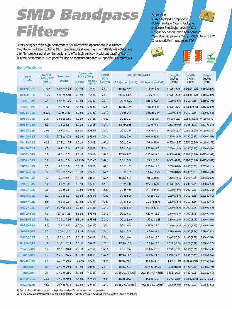
Features• Small Size • Fully Shielded Component• Solder Surface Mount Package• Moisture Sensitivity Level: MSL1• Frequency Stable over Temperature• Operating & Storage Temp: -55˚C to +125˚C• Characteristic Impedance: 50Ω
Features• Small Size• Fully Shielded Component• Frequency Stable over Temperature• Solder Surface Mountable• Excellent Repeatability• Operating Temp: -55˚C to +125˚C• Characteristic Impedance: 50Ω• 100% Tested & Inspected
Specifications
Part Number
3 dB Cutoff(GHz)
Passband(GHz)
Max Insertion
Loss in Passband
Min VSWR
in Passband
MountingMin
RejectionGHz (30dB)
Length Inches (mm)
Width Inches (mm)
Height Inches (mm)
L050XF9S 5.0 DC - 4.0 1.0 dB 1.288:1 SMD 6.0 to 18.0 0.220 (5.59) 0.180 (4.57) 0.103 (2.62)
L065XG9W 6.5 DC to 6.0 1.3 dB 1.33:1 WB 8.0 to 24.5 0.220 (5.59) 0.140 (3.56) 0.118 (3.0)
L065XG9S 6.5 DC - 6.0 1.3 dB 1.22:1 SMD 7.9 to 26.0 0.220 (5.59) 0.180 (4.57) 0.103 (2.62)
L095XG9S 9.5 DC - 9.0 1.3 dB 1.12:1 SMD 11.5 to 32.0 0.220 (5.59) 0.140 (3.56) 0.103 (2.62)
L117XH4S 11.7 DC - 11.0 1.0 dB 1.43:1 SMD 17.0 to 32.0 0.220 (5.59) 0.140 (3.56) 0.103 (2.62)
L128XH4S 12.8 DC - 12.0 1.2 dB 1.38:1 SMD 18.8 to 34.5 0.220 (5.59) 0.140 (3.56) 0.103 (2.62)
L117XH4W 13.1 DC to 12.6 2.0 dB 1.67:1 WB 17.0 to 35.0 0.220 (5.59) 0.140 (3.56) 0.113 (2.87)
L157XG3S 15.7 DC - 15.0 2.2 dB 1.3:1 SMD 20.0 to 35.5 0.220 (5.59) 0.140 (3.56) 0.103 (2.62)
L157XF3W 17.0 DC to 16.5 2.0 dB 1.67:1 WB 20.0 to 38.0 0.220 (5.58) 0.140 (3.56) 0.108 (2.74)
L185XF4S 18.5 DC - 18.0 2.2 dB 1.4:1 SMD 22.5 to 42.5 0.220 (5.59) 0.140 (3.56) 0.098 (2.49)
L185XF4W 18.5 DC to 18.0 2.0 dB 2.0:1 WB 21.0 to 40.0 0.220 (5.59) 0.140 (3.56) 0.113 (2.87)
L204XF4S 20.4 DC - 20.0 1.8 dB 1.43:1 SMD 23.0 to 43.0 0.220 (5.59) 0.140 (3.56) 0.098 (2.49)
L254XF3S 25.4 DC - 25.0 1.4 dB 1.3:1 SMD 29.0 to 50.0 0.220 (5.59) 0.140 (3.56) 0.098 (2.49)
L288XC3S 28.6 DC to 27.65 2.0 dB 1.92 :1 SMD 30.5 to 50.0 0.220 (5.58) 0.140 (3.56) 0.098 (2.49)
Highpass FiltersDLI introduces its new high frequency surface mountable catalog Highpass filters. These HPF’s incorporate DLI’s low loss high permittivity ceramics which provide small size and temperature stability. The catalog HPF’s are offered in a variety of frequency bands, which offers a drop in solution for high frequency attenuation.
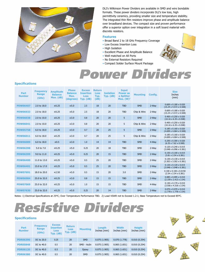
DLI’s Wilkinson Power Dividers are available in SMD and wire bondable formats. These power dividers incorporate DLI’s low loss, high permittivity ceramics, providing smaller size and temperature stability. The integrated thin film resistors improve phase and amplitude balance over broadband devices. The compact size and proven performance offer a superior option over integration in a soft board material with discrete resistors.
Features• Broad Band 2 to 18 GHz Frequency Coverage• Low Excess Insertion Loss• High Isolation• Excellent Phase and Amplitude Balance• Well matched on All Ports• No External Resistors Required• Compact Solder Surface Mount Package
Specifications
Part Number
Frequency Range(GHz)
Amplitude Balance
Max. (dB)
Phase Balance
Max. (degrees)
Excess Insertion
Loss Typ. (dB)
Return Loss Typ. (dB)
Isolation Typ. (dB)
Input Power as a Splitter Max. (W)2
Mounting Config.Size
Inches (mm)
PDW06407 2.0 to 18.0 ±0.25 ±5.0 2.5 18 20 TBD SMD 2-Way 0.600 x 0.180 x 0.020(15.24 x 4.572 x 0.508)
PDW06933 2.0 to 18.0 ±0.25 ±5.0 2.5 18 20 TBD Chip & Wire 2-Way 0.600 x 0.180 x 0.020(15.24 x 4.572 x 0.508)
PDW06038 2.0 to 10.0 ±0.25 ±3.0 0.8 20 20 5 SMD 2-Way 0.400 x 0.250 x 0.020(10.16 x 6.35 x 0.508)
PDW06041 2.0 to 10.0 ±0.25 ±3.0 0.8 20 20 5 Chip & Wire 2-Way 0.400 x 0.250 x 0.020(10.16 x 6.35 x 0.508)
PDW05758 6.0 to 18.0 ±0.25 ±3.0 0.7 20 25 5 SMD 2-Way 0.185 x 0.160 x 0.020(4.699 x 4.064 x 0.508)
PDW06011 6.0 to 18.0 ±0.25 ±3.0 0.7 20 25 5 Chip & Wire 2-Way 0.185 x 0.160 x 0.020(4.699 x 4.064 x 0.508)
PDW06089 6.0 to 18.0 ±0.5 ±3.0 1.0 14 14 TBD SMD 4-Way 0.250 x 0.300 x 0.020(6.35 x 7.62 x 0.508)
PDW06398 5.0 to 7.0 ±0.25 ±5.0 0.25 20 18 TBD SMD 2-Way 0.120 x 0.240 x 0.015(3.048 x 6.096 x 0.381)
PDW06399 9.0 to 11.0 ±0.25 ±5.0 0.25 20 15 TBD SMD 2-Way 0.150 x 0.100 x 0.015(3.81 x 2.54 x 0.381)
PDW06400 11.0 to 13.0 ±0.25 ±5.0 0.5 25 20 TBD SMD 2-Way 0.130 x 0.130 x 0.015(3.302 x 3.302 x 0.381)
PDW06401 15.0 to 17.0 ±0.25 ±5.0 0.5 25 20 TBD SMD 2-Way 0.120 x 0.120 x 0.015(3.048 x 3.048 x 0.381)
PDW07691 18.0 to 20.0 ±2.50 ±5.0 0.5 15 20 3.0 SMD 2-Way 0.100 x 0.100 x 0.0150(2.54 x 2.54 x 0.381)
PDW06984 25.0 to 32.0 ±0.25 ±3.0 0.8 15 15 TBD SMD 2-Way 0.085 x 0.095 x 0.010(2.159 x 2.413 x 2.54)
PDW07069 25.0 to 32.0 ±0.25 ±5.0 1.0 15 15 TBD SMD 4-Way 0.140 x 0.170 x 0.010(3.556 x 4.318 x 2.54)
PDW07630 25.0 to 32.0 ±0.25 ±5.0 0.25 20 14 TBD SMD 2-Way 0.070 x 0.070 x 0.010(1.778 x 1.778 x 2.54)
Notes: 1) Electrical Specifications at 25ºC; Over Temperature Performance TBD. 2) Load VSWR not to Exceed 1.2:1; Base Temperature not to Exceed 85ºC.
Features• Small Size • High Directivity • Frequency Stable over Temperature• Solder Surface Mountable • Excellent Repeatability• Operating Temp: -55˚C to +125˚C • Characteristic Impedance: 50Ω• Flexible PCB Feed Line Configurations
Specifications
Part Number
Center Frequency
(GHz)
Passband(GHz)
Insertion Loss (@Fc) VSWR
50Ω System
Rejection (GHz) LengthInches(mm)
WidthInches(mm)
HeightInches(mm)@ 25ºC -40ºC to
+85ºC LS Rejection (40dB) HS Rejection (40dB)
B012MD5S 1.227 1.22 to 1.23 3.5 dB 4.2 dB 2.0:1 DC to .925 1.45 to 2.5 0.460 (11.68) 0.460 (11.68) 0.113 (2.87)
B016MD6S 1.575 1.57 to 1.58 3.5 dB 4.2 dB 2.0:1 DC to 1.175 1.875 to 3.0 0.460 (11.68) 0.460 (11.68) 0.113 (2.87)
B024RF2S 2.4 1.97 to 3.05 3.0 dB 3.5 dB 2.0:1 DC to 1.25 3.8 to 4.75 0.500 (12.7) 0.250 (6.35) 0.110 (2.79)
B028RF2S 3.0 2.0 to 4.0 2.5 dB 3.0 dB 1.63:1 DC to 1.25 4.85 to 6.0 0.450 (11.43) 0.400 (10.16) 0.113 (2.87)
B031ND5S 3.125 2.9 to 3.33 3.0 dB 3.5 dB 2.0:1 DC to 2.4 3.85 to 7.0 0.500 (12.7) 0.250 (6.35) 0.100 (2.54)
B032ND5S 3.24 2.95 to 3.55 3.0 dB 3.5 dB 1.67:1 DC to 2.3 4.1 to 7.0 0.500 (12.7) 0.250 (6.35) 0.110 (2.79)
B033ND5S 3.3 3.1 to 3.5 2.0 dB 3.2 dB 2.0:1 DC to 2.25 4.0 to 6.0 0.393 (9.98) 0.353 (8.97) 0.128 (3.25)
B039NC5S 3.95 3.7 to 4.2 2.5 dB 2.75 dB 2.0:1 DC to 3.0 4.8 to 8.0 0.500 (12.7) 0.250 (6.35) 0.110 (2.79)
B040MB5S 4.0 3.78 to 4.22 2.5 dB 2.75 dB 2.0:1 DC to 3.4 4.6 to 10.0 0.500 (12.7) 0.250 (6.35) 0.100 (2.54)
B042ND4S 4.25 3.75 to 4.75 3.0 dB 3.5 dB 1.67:1 DC to 3.0 5.6 to 10.0 0.500 (12.7) 0.250 (6.35) 0.110 (2.79)
B047MC5S 4.7 4.4 to 5.0 2.0 dB 2.5 dB 2.0:1 DC to 3.8 5.55 to 11.0 0.500 (12.7) 0.250 (6.35) 0.100 (2.54)
B050NC4S 5.0 4.5 to 5.5 2.0 dB 2.5 dB 1.67:1 DC to 3.65 6.15 to 12.0 0.350 (8.89) 0.200 (5.08) 0.095 (2.41)
B052NC5S 5.2 4.8 to 5.6 2.25 dB 2.75 dB 1.67:1 DC to 3.5 6.2 to 12.5 0.350 (8.89) 0.200 (5.08) 0.095 (2.41)
B055NC5S 5.5 5.0 to 6.0 2.0 dB 2.5 dB 1.67:1 DC to 4.2 6.75 to 12.0 0.350 (8.89) 0.200 (5.08) 0.095 (2.41)
B057MC5S 5.7 5.45 to 5.95 2.0 dB 2.5 dB 1.67:1 DC to 4.7 6.6 to 14.25 0.350 (8.89) 0.200 (5.08) 0.110 (2.79)
B058MD7S 5.7 5.5 to 6.1 2.3 dB 2.8 dB 1.67:1 DC to 4.65 7.0 to 16.0 0.475 (12.1) 0.275 (7.00) 0.103 (2.62)
B056RC4S 6.0 4.0 to 8.0 3.0 dB 3.5 dB 1.5:1 DC to 3.0 9.5 to 12.0 0.450 (11.43) 0.230 (5.84) 0.100 (2.54)
B060NC5S 6.0 5.5 to 6.5 2.0 dB 3.0 dB 1.29:1 DC to 4.9 7.1 to 14.0 0.500 (12.7) 0.200 (5.08) 0.088 (2.24)
B062MC5S 6.3 5.9 to 6.7 2.5 dB 2.75 dB 1.67:1 DC to 5.2 7.5 to 15.0 0.500 (12.7) 0.250 (6.35) 0.095 (2.41)
B065NC5S 6.5 6.0 to 7.0 3.0 dB 3.5 dB 1.67:1 DC to 5.2 7.75 to 15.0 0.500 (12.7) 0.250 (6.35) 0.095 (2.41)
B070NC5S 7.0 6.37 to 7.63 2.0 dB 2.5 dB 2.0:1 DC to 5.8 8.5 to 17.5 0.500 (12.7) 0.200 (5.08) 0.100 (2.54)
B070MB6S 7.1 6.7 to 7.25 2.5 dB 2.75 dB 2.0:1 DC to 6.2 7.82 to 15.0 0.500 (12.7) 0.200 (5.08) 0.100 (2.54)
B076MB6S 7.6 7.24 to 7.96 2.5 dB 2.75 dB 2.0:1 DC to 6.69 8.52 to 18.25 0.500 (12.7) 0.200 (5.08) 0.100 (2.54)
B080MB5S 8.0 7.5 to 8.5 2.0 dB 3.0 dB 1.29:1 DC to 6.8 9.25 to 17.0 0.500 (12.7) 0.180 (4.57) 0.100 (2.54)
B081RC0S 8.5 6.0 to 11.0 3.4 dB 3.9 dB 2.0:1 DC to 3.5 14.0 to 19.0 0.190 (4.83) 0.100 (2.54) 0.090 (2.87)
B096QC2S 10 8.0 to 12.0 2.5 dB 3.0 dB 2.0:1 DC to 6.0 14.0 to 18.0 0.400 (10.86) 0.180 (4.57) 0.100 (2.54)
B120MB1S 12 11.5 to 12.5 2.0 dB 3.0 dB 1.29:1 DC to 10.6 13.2 to 19.5 0.525 (13.34) 0.225 (5.72) 0.090 (2.27)
B148QF0S 15 12.0 to 18.0 3.6 dB 4.2 dB 1.63:1 DC to 7.6 23.0 to 25.0 0.550 (13.97) 0.150 (3.81) 0.098 (2.49)
B161LA0S 16 15.5 to 16.5 4.0 dB 6.0 dB 1.67:1 DC to 14.5 17.2 to 21.5 0.695 (17.65) 0.250 (6.35) 0.093 (2.36)
B274MB1S 28 26.5 to 29.5 3.25 dB 3.5 dB 1.92:1 DC to 24.0 31.0 to 39.0 0.450 11.43) 0.110 (2.794) 0.089 (2.26)
B280LB0S 28 27.0 to 29.0 1.5 dB 2.0 dB 2.0:1 DC to 25.0 30.75 to 34.25 0.350 (8.89) 0.120 (3.05) 0.098 (2.49)
B280LA0S 28 27.5 to 28.5 4.0 dB 4.5 dB 2.0:1 DC to 26.0 (35dB) 29.5 to 37.5 (30dB) 0.550 (14.00) 0.140 (3.56) 0.083 (2.11)
B385MD0S 38.5 37.0 to 40.0 2.5 dB 2.75 dB 1.92:1 DC to 34.0 45.0 to 50.0 0.275 (6.985) 0.080 (2.032) 0.075 (1.905)
B424MEZS 42.5 39.7 to 45.3 1.5 dB 2.0 dB 2.0:1 DC to 37.0 (30dB) 47.5 to 60.0 (30dB) 0.236 (6.00) 0.080 (2.03) 0.065 (1.65)
1) Electrical specifications based on typical probed performance at room temperature. 2) Above parts can be supplied in wire bondable format (epoxy and Au wire bond), please consult factory for details.
Specifications
Part Number
Frequency Range (GHz)
Mean Coupling
Value (dB)
Max Insertion
Loss (dB)
Return Loss Typ. (dB)
Size Inches (mm)
FPC06882 DC to 25 25 2 12 0.060 x 0.088 x 0.010(15.24 x 2.235 x 2.54)
FPC06881 DC to 25 20 2 12 0.060 x 0.088 x 0.010(15.24 x 2.235 x 2.54)
FPC07802 DC to 40 25 2.5 12 0.060 x 0.088 x 0.010(15.24 x 2.235 x 2.54)
FPC07803 DC to 40 17 3 12 0.060 x 0.088 x 0.010(15.24 x 2.235 x 2.54)
DLI’s surface mount directional coupler series now cover up to 40 GHz. While custom coupling values are achievable, offerings in 3, 10 and 20 dB are available with common footprints for maximum flexibility. These couplers offer a turnkey solution in SMD or Chip and Wire format for high frequency power monitoring. Custom solutions are also available.
Specifications
Part Number
Frequency Range (GHz)
Mean Coupling
Value (dB)
Passband Coupling Variation Typ. (dB)
Insertion Loss
Typ. (dB)
Return Loss
Typ. (dB) Isolation Typ. (dB)
Directivity Typ. (dB) Mounting
Size Inches (mm)
FPC06700 5.9 to 6.5 3 1.0 0.5 15 20 17 SMD 0.425 x 0.250 x 0.020(10.795 x 6.35 x 0.508)
FPC06630 9.0 to 11.0 3 NA 0.5 15 18 15 SMD 0.286 x 0.180 x 0.015 (7.264 x 4.57 x 0.381)
FPC06701 10.7 to 12.75 3 1.0 0.5 12 15 12 SMD 0.255 x 0.155 x 0.015(6.477 x 3.937 x 0.381)
FPC07180 2.0 to 18.0 20 4.5 0.8 15 20 20 SMD 0.500 x 0.150 x 0.015(12.7 x 3.81 x 0.381)
FPC07183 24.0 to 33.0 3 ± 0.5 0.5 15 15 12 SMD 0.180 x 0.110 x 0.010 (4.572 x 2.794 x 2.54)
FPC06073 4.0 to 8.0 10 ± 1.5 0.3 20 30 20 SMD 0.170 x 0.080 x 0.015(4.318 x 2.032 x 0.381)
FPC06149 4.0 to 8.0 10 N/A 0.3 18 30 20 Chip & Wire 0.180 x 0.080 x 0.015(4.572 x 2.032 x 0.381)
FPC06076 4.0 to 8.0 20 ± 1.5 0.3 20 40 20 SMD 0.170 x 0.080 x 0.015(4.318 x 2.032 x 0.381)
FPC06152 4.0 to 8.0 20 N/A 0.3 15 35 16 Chip & Wire 0.180 x 0.080 x 0.015(4.572 x 2.032 x 0.381)
FPC06719 6.0 to 18.0 10 1.0 0.3 15 20 10 SMD 0.255 x 0.100 x 0.015(6.477 x 2.54 x 0.381)
FPC06913 6.0 to 18.0 20 1.0 0.3 12 28 8 SMD 0.180 x 0.110 x 0.015(4.572 x 2.794 x 0.381)
FPC06074 8.0 to 12.0 10 ± 1.0 0.3 14 25 15 SMD 0.120 x 0.080 x 0.015(3.048 x 2.032 x 0.381)
FPC06150 8.0 to 12.0 10 N/A 0.3 12 18 8 Chip & Wire 0.130 x 0.090 x 0.015(3.302 x 2.286 x 0.381)
FPC06153 8.0 to 12.0 20 N/A 0.3 15 30 12 Chip & Wire 0.130 x 0.090 x 0.015(3.302 x 2.286 x 0.381)
FPC06302 8.0 to 12.0 20 N/A 0.3 15 35 15 SMD 0.120 x 0.080 x 0.015(3.048 x 2.032 x 0.381)
FPC06077 8.0 to 12.0 25 ± 1.0 0.3 15 30 10 SMD 0.120 x 0.080 x 0.015(3.048 x 2.032 x 0.381)
FPC06075 12.0 to 18.0 10 ± 0.5 0.3 15 25 14 SMD 0.100 x 0.080 x 0.015(2.54 x 2.032 x 0.381)
FPC06151 12.0 to 18.0 10 N/A 0.5 12 18 10 Chip & Wire 0.100 x 0.080 x 0.015(2.54 x 2.032 x 0.381)
FPC06078 12.0 to 18.0 20 ± 1.0 0.3 15 35 14 SMD 0.100 x 0.080 x 0.015(2.54 x 2.032 x 0.381)
FPC06154 12.0 to 18.0 20 N/A 0.3 10 15 10 Chip & Wire 0.100 x 0.080 x 0.015(2.54 x 2.032 x 0.381)
FPC07182 20.0 to 40.0 10 ± 1.5 0.3 10 28 15 SMD 0.065 x 0.050 x 0.010(1.651 x 1.27 x 2.54)
FPC07181 20.0 to 40.0 20 ± 1.5 0.3 12 34 10 SMD 0.065 x 0.050 x 0.010(1.651 x 1.27 x 2.54)
Filters designed with high performance for microwave applications in a surface mountable package. Utilizing DLI’s temperature stable, high permittivity dielectrics and thin film processing allow the designs to offer high selectivity without sacrificing on in-band performance. Designed for use on industry standard RF specific PCB materials.
These LPF’s incorporate DLI’s low loss high permittivity ceramics which provide small size and temperature stability. The catalog LPF’s are offered in a variety of frequency bands, which offers a drop in solution for high frequency attenuation. With extreme repeatability, can place multiple in series for increased rejection or speak to the factory for a custom solution.
Cert
ified
Sys
tem TM
ISO 14001
Cert
ified
Sys
tem TM
ISO 9001:2000& AS9100B
Specifications
Part Number
Frequency Range(GHz)
Excess Insertion
Loss Typ. (dB)
Return Loss
Typ. (dB)Mounting Length
Inches (mm)Width
Inches (mm)Height
Inches (mm)
PDR06390 DC to 20.0 0.25 20 SMD 0.075 (1.905) 0.070 (1.778) 0.010 (0.254)
PDR05848 DC to 40.0 0.5 20 SMD - AuSn 0.075 (1.905) 0.065 (1.651) 0.010 (0.254)
PDR06120 DC to 40.0 0.5 20 Epoxy 0.075 (1.905) 0.065 (1.651) 0.010 (0.254)
PDR06380 DC to 40.0 0.5 20 SMD 0.075 (1.905) 0.065 (1.651) 0.010 (0.254)
Specifications
Part Number
3dB cutoff(GHz)
Passband(GHz)
Typical Insertion Loss in Passband
Minimum VSWR in Passband
Minimum Rejection
GHz (30dB)
Length Inches (mm)
Width Inches (mm)
Height Inches (mm)
H060XHXS 6.0 6.5 - 20.0 1.0 dB 1.43:1 DC to 3.5 0.450 (11.43) 0.200 (5.08) 0.093 (2.362)
H080XHXS 8.0 8.5 - 22.0 1.0 dB 1.43:1 DC to 5.0 0.450 (11.43) 0.200 (5.08) 0.093 (2.362)
H100XHXS 10.0 10.5 - 23.0 1.0 dB 1.43:1 DC to 5.5 0.450 (11.43) 0.175 (4.445) 0.083 (2.108)
H120XHXS 12.0 12.5 - 30.0 1.0 dB 1.43:1 DC to 9.0 0.450 (11.43) 0.175 (4.445) 0.083 (2.108)
H140XHXS 14.0 14.5 - 28.0 1.0 dB 1.43:1 DC to 9.5 0.450 (11.43) 0.175 (4.445) 0.083 (2.108)
H160XHXS 16.0 16.5 - 32.5 1.0 dB 1.43:1 DC to 12.1 0.450 (11.43) 0.175 (4.445) 0.083 (2.108)
H168XHXS 17.0 18.0 - 30.0 1.0 dB 1.43:1 DC to 11.6 0.450 (11.43) 0.175 (4.445) 0.083 (2.108)
H182XHXS 18.2 19.0 - 28.0 1.0 dB 1.7:1 DC to 14.0 0.450 (11.43) 0.175 (4.445) 0.083 (2.108)

SMD Bandpass Filters
Power Dividers
Resistive Dividers
Resistive Couplers
Lowpass Filters
Couplers
Features• Small Size • Fully Shielded Component• Solder Surface Mount Package• Moisture Sensitivity Level: MSL1• Frequency Stable over Temperature• Operating & Storage Temp: -55˚C to +125˚C• Characteristic Impedance: 50Ω
Features• Small Size• Fully Shielded Component• Frequency Stable over Temperature• Solder Surface Mountable• Excellent Repeatability• Operating Temp: -55˚C to +125˚C• Characteristic Impedance: 50Ω• 100% Tested & Inspected
Specifications
Part Number
3 dB Cutoff(GHz)
Passband(GHz)
Max Insertion
Loss in Passband
Min VSWR
in Passband
MountingMin
RejectionGHz (30dB)
Length Inches (mm)
Width Inches (mm)
Height Inches (mm)
L050XF9S 5.0 DC - 4.0 1.0 dB 1.288:1 SMD 6.0 to 18.0 0.220 (5.59) 0.180 (4.57) 0.103 (2.62)
L065XG9W 6.5 DC to 6.0 1.3 dB 1.33:1 WB 8.0 to 24.5 0.220 (5.59) 0.140 (3.56) 0.118 (3.0)
L065XG9S 6.5 DC - 6.0 1.3 dB 1.22:1 SMD 7.9 to 26.0 0.220 (5.59) 0.180 (4.57) 0.103 (2.62)
L095XG9S 9.5 DC - 9.0 1.3 dB 1.12:1 SMD 11.5 to 32.0 0.220 (5.59) 0.140 (3.56) 0.103 (2.62)
L117XH4S 11.7 DC - 11.0 1.0 dB 1.43:1 SMD 17.0 to 32.0 0.220 (5.59) 0.140 (3.56) 0.103 (2.62)
L128XH4S 12.8 DC - 12.0 1.2 dB 1.38:1 SMD 18.8 to 34.5 0.220 (5.59) 0.140 (3.56) 0.103 (2.62)
L117XH4W 13.1 DC to 12.6 2.0 dB 1.67:1 WB 17.0 to 35.0 0.220 (5.59) 0.140 (3.56) 0.113 (2.87)
L157XG3S 15.7 DC - 15.0 2.2 dB 1.3:1 SMD 20.0 to 35.5 0.220 (5.59) 0.140 (3.56) 0.103 (2.62)
L157XF3W 17.0 DC to 16.5 2.0 dB 1.67:1 WB 20.0 to 38.0 0.220 (5.58) 0.140 (3.56) 0.108 (2.74)
L185XF4S 18.5 DC - 18.0 2.2 dB 1.4:1 SMD 22.5 to 42.5 0.220 (5.59) 0.140 (3.56) 0.098 (2.49)
L185XF4W 18.5 DC to 18.0 2.0 dB 2.0:1 WB 21.0 to 40.0 0.220 (5.59) 0.140 (3.56) 0.113 (2.87)
L204XF4S 20.4 DC - 20.0 1.8 dB 1.43:1 SMD 23.0 to 43.0 0.220 (5.59) 0.140 (3.56) 0.098 (2.49)
L254XF3S 25.4 DC - 25.0 1.4 dB 1.3:1 SMD 29.0 to 50.0 0.220 (5.59) 0.140 (3.56) 0.098 (2.49)
L288XC3S 28.6 DC to 27.65 2.0 dB 1.92 :1 SMD 30.5 to 50.0 0.220 (5.58) 0.140 (3.56) 0.098 (2.49)
Highpass FiltersDLI introduces its new high frequency surface mountable catalog Highpass filters. These HPF’s incorporate DLI’s low loss high permittivity ceramics which provide small size and temperature stability. The catalog HPF’s are offered in a variety of frequency bands, which offers a drop in solution for high frequency attenuation.
DLI’s Wilkinson Power Dividers are available in SMD and wire bondable formats. These power dividers incorporate DLI’s low loss, high permittivity ceramics, providing smaller size and temperature stability. The integrated thin film resistors improve phase and amplitude balance over broadband devices. The compact size and proven performance offer a superior option over integration in a soft board material with discrete resistors.
Features• Broad Band 2 to 18 GHz Frequency Coverage• Low Excess Insertion Loss• High Isolation• Excellent Phase and Amplitude Balance• Well matched on All Ports• No External Resistors Required• Compact Solder Surface Mount Package
Specifications
Part Number
Frequency Range(GHz)
Amplitude Balance
Max. (dB)
Phase Balance
Max. (degrees)
Excess Insertion
Loss Typ. (dB)
Return Loss Typ. (dB)
Isolation Typ. (dB)
Input Power as a Splitter Max. (W)2
Mounting Config.Size
Inches (mm)
PDW06407 2.0 to 18.0 ±0.25 ±5.0 2.5 18 20 TBD SMD 2-Way 0.600 x 0.180 x 0.020(15.24 x 4.572 x 0.508)
PDW06933 2.0 to 18.0 ±0.25 ±5.0 2.5 18 20 TBD Chip & Wire 2-Way 0.600 x 0.180 x 0.020(15.24 x 4.572 x 0.508)
PDW06038 2.0 to 10.0 ±0.25 ±3.0 0.8 20 20 5 SMD 2-Way 0.400 x 0.250 x 0.020(10.16 x 6.35 x 0.508)
PDW06041 2.0 to 10.0 ±0.25 ±3.0 0.8 20 20 5 Chip & Wire 2-Way 0.400 x 0.250 x 0.020(10.16 x 6.35 x 0.508)
PDW05758 6.0 to 18.0 ±0.25 ±3.0 0.7 20 25 5 SMD 2-Way 0.185 x 0.160 x 0.020(4.699 x 4.064 x 0.508)
PDW06011 6.0 to 18.0 ±0.25 ±3.0 0.7 20 25 5 Chip & Wire 2-Way 0.185 x 0.160 x 0.020(4.699 x 4.064 x 0.508)
PDW06089 6.0 to 18.0 ±0.5 ±3.0 1.0 14 14 TBD SMD 4-Way 0.250 x 0.300 x 0.020(6.35 x 7.62 x 0.508)
PDW06398 5.0 to 7.0 ±0.25 ±5.0 0.25 20 18 TBD SMD 2-Way 0.120 x 0.240 x 0.015(3.048 x 6.096 x 0.381)
PDW06399 9.0 to 11.0 ±0.25 ±5.0 0.25 20 15 TBD SMD 2-Way 0.150 x 0.100 x 0.015(3.81 x 2.54 x 0.381)
PDW06400 11.0 to 13.0 ±0.25 ±5.0 0.5 25 20 TBD SMD 2-Way 0.130 x 0.130 x 0.015(3.302 x 3.302 x 0.381)
PDW06401 15.0 to 17.0 ±0.25 ±5.0 0.5 25 20 TBD SMD 2-Way 0.120 x 0.120 x 0.015(3.048 x 3.048 x 0.381)
PDW07691 18.0 to 20.0 ±2.50 ±5.0 0.5 15 20 3.0 SMD 2-Way 0.100 x 0.100 x 0.0150(2.54 x 2.54 x 0.381)
PDW06984 25.0 to 32.0 ±0.25 ±3.0 0.8 15 15 TBD SMD 2-Way 0.085 x 0.095 x 0.010(2.159 x 2.413 x 2.54)
PDW07069 25.0 to 32.0 ±0.25 ±5.0 1.0 15 15 TBD SMD 4-Way 0.140 x 0.170 x 0.010(3.556 x 4.318 x 2.54)
PDW07630 25.0 to 32.0 ±0.25 ±5.0 0.25 20 14 TBD SMD 2-Way 0.070 x 0.070 x 0.010(1.778 x 1.778 x 2.54)
Notes: 1) Electrical Specifications at 25ºC; Over Temperature Performance TBD. 2) Load VSWR not to Exceed 1.2:1; Base Temperature not to Exceed 85ºC.
Features• Small Size • High Directivity • Frequency Stable over Temperature• Solder Surface Mountable • Excellent Repeatability• Operating Temp: -55˚C to +125˚C • Characteristic Impedance: 50Ω• Flexible PCB Feed Line Configurations
Specifications
Part Number
Center Frequency
(GHz)
Passband(GHz)
Insertion Loss (@Fc) VSWR
50Ω System
Rejection (GHz) LengthInches(mm)
WidthInches(mm)
HeightInches(mm)@ 25ºC -40ºC to
+85ºC LS Rejection (40dB) HS Rejection (40dB)
B012MD5S 1.227 1.22 to 1.23 3.5 dB 4.2 dB 2.0:1 DC to .925 1.45 to 2.5 0.460 (11.68) 0.460 (11.68) 0.113 (2.87)
B016MD6S 1.575 1.57 to 1.58 3.5 dB 4.2 dB 2.0:1 DC to 1.175 1.875 to 3.0 0.460 (11.68) 0.460 (11.68) 0.113 (2.87)
B024RF2S 2.4 1.97 to 3.05 3.0 dB 3.5 dB 2.0:1 DC to 1.25 3.8 to 4.75 0.500 (12.7) 0.250 (6.35) 0.110 (2.79)
B028RF2S 3.0 2.0 to 4.0 2.5 dB 3.0 dB 1.63:1 DC to 1.25 4.85 to 6.0 0.450 (11.43) 0.400 (10.16) 0.113 (2.87)
B031ND5S 3.125 2.9 to 3.33 3.0 dB 3.5 dB 2.0:1 DC to 2.4 3.85 to 7.0 0.500 (12.7) 0.250 (6.35) 0.100 (2.54)
B032ND5S 3.24 2.95 to 3.55 3.0 dB 3.5 dB 1.67:1 DC to 2.3 4.1 to 7.0 0.500 (12.7) 0.250 (6.35) 0.110 (2.79)
B033ND5S 3.3 3.1 to 3.5 2.0 dB 3.2 dB 2.0:1 DC to 2.25 4.0 to 6.0 0.393 (9.98) 0.353 (8.97) 0.128 (3.25)
B039NC5S 3.95 3.7 to 4.2 2.5 dB 2.75 dB 2.0:1 DC to 3.0 4.8 to 8.0 0.500 (12.7) 0.250 (6.35) 0.110 (2.79)
B040MB5S 4.0 3.78 to 4.22 2.5 dB 2.75 dB 2.0:1 DC to 3.4 4.6 to 10.0 0.500 (12.7) 0.250 (6.35) 0.100 (2.54)
B042ND4S 4.25 3.75 to 4.75 3.0 dB 3.5 dB 1.67:1 DC to 3.0 5.6 to 10.0 0.500 (12.7) 0.250 (6.35) 0.110 (2.79)
B047MC5S 4.7 4.4 to 5.0 2.0 dB 2.5 dB 2.0:1 DC to 3.8 5.55 to 11.0 0.500 (12.7) 0.250 (6.35) 0.100 (2.54)
B050NC4S 5.0 4.5 to 5.5 2.0 dB 2.5 dB 1.67:1 DC to 3.65 6.15 to 12.0 0.350 (8.89) 0.200 (5.08) 0.095 (2.41)
B052NC5S 5.2 4.8 to 5.6 2.25 dB 2.75 dB 1.67:1 DC to 3.5 6.2 to 12.5 0.350 (8.89) 0.200 (5.08) 0.095 (2.41)
B055NC5S 5.5 5.0 to 6.0 2.0 dB 2.5 dB 1.67:1 DC to 4.2 6.75 to 12.0 0.350 (8.89) 0.200 (5.08) 0.095 (2.41)
B057MC5S 5.7 5.45 to 5.95 2.0 dB 2.5 dB 1.67:1 DC to 4.7 6.6 to 14.25 0.350 (8.89) 0.200 (5.08) 0.110 (2.79)
B058MD7S 5.7 5.5 to 6.1 2.3 dB 2.8 dB 1.67:1 DC to 4.65 7.0 to 16.0 0.475 (12.1) 0.275 (7.00) 0.103 (2.62)
B056RC4S 6.0 4.0 to 8.0 3.0 dB 3.5 dB 1.5:1 DC to 3.0 9.5 to 12.0 0.450 (11.43) 0.230 (5.84) 0.100 (2.54)
B060NC5S 6.0 5.5 to 6.5 2.0 dB 3.0 dB 1.29:1 DC to 4.9 7.1 to 14.0 0.500 (12.7) 0.200 (5.08) 0.088 (2.24)
B062MC5S 6.3 5.9 to 6.7 2.5 dB 2.75 dB 1.67:1 DC to 5.2 7.5 to 15.0 0.500 (12.7) 0.250 (6.35) 0.095 (2.41)
B065NC5S 6.5 6.0 to 7.0 3.0 dB 3.5 dB 1.67:1 DC to 5.2 7.75 to 15.0 0.500 (12.7) 0.250 (6.35) 0.095 (2.41)
B070NC5S 7.0 6.37 to 7.63 2.0 dB 2.5 dB 2.0:1 DC to 5.8 8.5 to 17.5 0.500 (12.7) 0.200 (5.08) 0.100 (2.54)
B070MB6S 7.1 6.7 to 7.25 2.5 dB 2.75 dB 2.0:1 DC to 6.2 7.82 to 15.0 0.500 (12.7) 0.200 (5.08) 0.100 (2.54)
B076MB6S 7.6 7.24 to 7.96 2.5 dB 2.75 dB 2.0:1 DC to 6.69 8.52 to 18.25 0.500 (12.7) 0.200 (5.08) 0.100 (2.54)
B080MB5S 8.0 7.5 to 8.5 2.0 dB 3.0 dB 1.29:1 DC to 6.8 9.25 to 17.0 0.500 (12.7) 0.180 (4.57) 0.100 (2.54)
B081RC0S 8.5 6.0 to 11.0 3.4 dB 3.9 dB 2.0:1 DC to 3.5 14.0 to 19.0 0.190 (4.83) 0.100 (2.54) 0.090 (2.87)
B096QC2S 10 8.0 to 12.0 2.5 dB 3.0 dB 2.0:1 DC to 6.0 14.0 to 18.0 0.400 (10.86) 0.180 (4.57) 0.100 (2.54)
B120MB1S 12 11.5 to 12.5 2.0 dB 3.0 dB 1.29:1 DC to 10.6 13.2 to 19.5 0.525 (13.34) 0.225 (5.72) 0.090 (2.27)
B148QF0S 15 12.0 to 18.0 3.6 dB 4.2 dB 1.63:1 DC to 7.6 23.0 to 25.0 0.550 (13.97) 0.150 (3.81) 0.098 (2.49)
B161LA0S 16 15.5 to 16.5 4.0 dB 6.0 dB 1.67:1 DC to 14.5 17.2 to 21.5 0.695 (17.65) 0.250 (6.35) 0.093 (2.36)
B274MB1S 28 26.5 to 29.5 3.25 dB 3.5 dB 1.92:1 DC to 24.0 31.0 to 39.0 0.450 11.43) 0.110 (2.794) 0.089 (2.26)
B280LB0S 28 27.0 to 29.0 1.5 dB 2.0 dB 2.0:1 DC to 25.0 30.75 to 34.25 0.350 (8.89) 0.120 (3.05) 0.098 (2.49)
B280LA0S 28 27.5 to 28.5 4.0 dB 4.5 dB 2.0:1 DC to 26.0 (35dB) 29.5 to 37.5 (30dB) 0.550 (14.00) 0.140 (3.56) 0.083 (2.11)
B385MD0S 38.5 37.0 to 40.0 2.5 dB 2.75 dB 1.92:1 DC to 34.0 45.0 to 50.0 0.275 (6.985) 0.080 (2.032) 0.075 (1.905)
B424MEZS 42.5 39.7 to 45.3 1.5 dB 2.0 dB 2.0:1 DC to 37.0 (30dB) 47.5 to 60.0 (30dB) 0.236 (6.00) 0.080 (2.03) 0.065 (1.65)
1) Electrical specifications based on typical probed performance at room temperature. 2) Above parts can be supplied in wire bondable format (epoxy and Au wire bond), please consult factory for details.
Specifications
Part Number
Frequency Range (GHz)
Mean Coupling
Value (dB)
Max Insertion
Loss (dB)
Return Loss Typ. (dB)
Size Inches (mm)
FPC06882 DC to 25 25 2 12 0.060 x 0.088 x 0.010(15.24 x 2.235 x 2.54)
FPC06881 DC to 25 20 2 12 0.060 x 0.088 x 0.010(15.24 x 2.235 x 2.54)
FPC07802 DC to 40 25 2.5 12 0.060 x 0.088 x 0.010(15.24 x 2.235 x 2.54)
FPC07803 DC to 40 17 3 12 0.060 x 0.088 x 0.010(15.24 x 2.235 x 2.54)
DLI’s surface mount directional coupler series now cover up to 40 GHz. While custom coupling values are achievable, offerings in 3, 10 and 20 dB are available with common footprints for maximum flexibility. These couplers offer a turnkey solution in SMD or Chip and Wire format for high frequency power monitoring. Custom solutions are also available.
Specifications
Part Number
Frequency Range (GHz)
Mean Coupling
Value (dB)
Passband Coupling Variation Typ. (dB)
Insertion Loss
Typ. (dB)
Return Loss
Typ. (dB) Isolation Typ. (dB)
Directivity Typ. (dB) Mounting
Size Inches (mm)
FPC06700 5.9 to 6.5 3 1.0 0.5 15 20 17 SMD 0.425 x 0.250 x 0.020(10.795 x 6.35 x 0.508)
FPC06630 9.0 to 11.0 3 NA 0.5 15 18 15 SMD 0.286 x 0.180 x 0.015 (7.264 x 4.57 x 0.381)
FPC06701 10.7 to 12.75 3 1.0 0.5 12 15 12 SMD 0.255 x 0.155 x 0.015(6.477 x 3.937 x 0.381)
FPC07180 2.0 to 18.0 20 4.5 0.8 15 20 20 SMD 0.500 x 0.150 x 0.015(12.7 x 3.81 x 0.381)
FPC07183 24.0 to 33.0 3 ± 0.5 0.5 15 15 12 SMD 0.180 x 0.110 x 0.010 (4.572 x 2.794 x 2.54)
FPC06073 4.0 to 8.0 10 ± 1.5 0.3 20 30 20 SMD 0.170 x 0.080 x 0.015(4.318 x 2.032 x 0.381)
FPC06149 4.0 to 8.0 10 N/A 0.3 18 30 20 Chip & Wire 0.180 x 0.080 x 0.015(4.572 x 2.032 x 0.381)
FPC06076 4.0 to 8.0 20 ± 1.5 0.3 20 40 20 SMD 0.170 x 0.080 x 0.015(4.318 x 2.032 x 0.381)
FPC06152 4.0 to 8.0 20 N/A 0.3 15 35 16 Chip & Wire 0.180 x 0.080 x 0.015(4.572 x 2.032 x 0.381)
FPC06719 6.0 to 18.0 10 1.0 0.3 15 20 10 SMD 0.255 x 0.100 x 0.015(6.477 x 2.54 x 0.381)
FPC06913 6.0 to 18.0 20 1.0 0.3 12 28 8 SMD 0.180 x 0.110 x 0.015(4.572 x 2.794 x 0.381)
FPC06074 8.0 to 12.0 10 ± 1.0 0.3 14 25 15 SMD 0.120 x 0.080 x 0.015(3.048 x 2.032 x 0.381)
FPC06150 8.0 to 12.0 10 N/A 0.3 12 18 8 Chip & Wire 0.130 x 0.090 x 0.015(3.302 x 2.286 x 0.381)
FPC06153 8.0 to 12.0 20 N/A 0.3 15 30 12 Chip & Wire 0.130 x 0.090 x 0.015(3.302 x 2.286 x 0.381)
FPC06302 8.0 to 12.0 20 N/A 0.3 15 35 15 SMD 0.120 x 0.080 x 0.015(3.048 x 2.032 x 0.381)
FPC06077 8.0 to 12.0 25 ± 1.0 0.3 15 30 10 SMD 0.120 x 0.080 x 0.015(3.048 x 2.032 x 0.381)
FPC06075 12.0 to 18.0 10 ± 0.5 0.3 15 25 14 SMD 0.100 x 0.080 x 0.015(2.54 x 2.032 x 0.381)
FPC06151 12.0 to 18.0 10 N/A 0.5 12 18 10 Chip & Wire 0.100 x 0.080 x 0.015(2.54 x 2.032 x 0.381)
FPC06078 12.0 to 18.0 20 ± 1.0 0.3 15 35 14 SMD 0.100 x 0.080 x 0.015(2.54 x 2.032 x 0.381)
FPC06154 12.0 to 18.0 20 N/A 0.3 10 15 10 Chip & Wire 0.100 x 0.080 x 0.015(2.54 x 2.032 x 0.381)
FPC07182 20.0 to 40.0 10 ± 1.5 0.3 10 28 15 SMD 0.065 x 0.050 x 0.010(1.651 x 1.27 x 2.54)
FPC07181 20.0 to 40.0 20 ± 1.5 0.3 12 34 10 SMD 0.065 x 0.050 x 0.010(1.651 x 1.27 x 2.54)
Filters designed with high performance for microwave applications in a surface mountable package. Utilizing DLI’s temperature stable, high permittivity dielectrics and thin film processing allow the designs to offer high selectivity without sacrificing on in-band performance. Designed for use on industry standard RF specific PCB materials.
These LPF’s incorporate DLI’s low loss high permittivity ceramics which provide small size and temperature stability. The catalog LPF’s are offered in a variety of frequency bands, which offers a drop in solution for high frequency attenuation. With extreme repeatability, can place multiple in series for increased rejection or speak to the factory for a custom solution.
Cert
ified
Sys
tem TM
ISO 14001
Cert
ified
Sys
tem TM
ISO 9001:2000& AS9100B
Specifications
Part Number
Frequency Range(GHz)
Excess Insertion
Loss Typ. (dB)
Return Loss
Typ. (dB)Mounting Length
Inches (mm)Width
Inches (mm)Height
Inches (mm)
PDR06390 DC to 20.0 0.25 20 SMD 0.075 (1.905) 0.070 (1.778) 0.010 (0.254)
PDR05848 DC to 40.0 0.5 20 SMD - AuSn 0.075 (1.905) 0.065 (1.651) 0.010 (0.254)
PDR06120 DC to 40.0 0.5 20 Epoxy 0.075 (1.905) 0.065 (1.651) 0.010 (0.254)
PDR06380 DC to 40.0 0.5 20 SMD 0.075 (1.905) 0.065 (1.651) 0.010 (0.254)
Specifications
Part Number
3dB cutoff(GHz)
Passband(GHz)
Typical Insertion Loss in Passband
Minimum VSWR in Passband
Minimum Rejection
GHz (30dB)
Length Inches (mm)
Width Inches (mm)
Height Inches (mm)
H060XHXS 6.0 6.5 - 20.0 1.0 dB 1.43:1 DC to 3.5 0.450 (11.43) 0.200 (5.08) 0.093 (2.362)
H080XHXS 8.0 8.5 - 22.0 1.0 dB 1.43:1 DC to 5.0 0.450 (11.43) 0.200 (5.08) 0.093 (2.362)
H100XHXS 10.0 10.5 - 23.0 1.0 dB 1.43:1 DC to 5.5 0.450 (11.43) 0.175 (4.445) 0.083 (2.108)
H120XHXS 12.0 12.5 - 30.0 1.0 dB 1.43:1 DC to 9.0 0.450 (11.43) 0.175 (4.445) 0.083 (2.108)
H140XHXS 14.0 14.5 - 28.0 1.0 dB 1.43:1 DC to 9.5 0.450 (11.43) 0.175 (4.445) 0.083 (2.108)
H160XHXS 16.0 16.5 - 32.5 1.0 dB 1.43:1 DC to 12.1 0.450 (11.43) 0.175 (4.445) 0.083 (2.108)
H168XHXS 17.0 18.0 - 30.0 1.0 dB 1.43:1 DC to 11.6 0.450 (11.43) 0.175 (4.445) 0.083 (2.108)
H182XHXS 18.2 19.0 - 28.0 1.0 dB 1.7:1 DC to 14.0 0.450 (11.43) 0.175 (4.445) 0.083 (2.108)

www.knowlesprecisiondevices.com
© Copyright Knowles Precision Devices, 2019 - design: [email protected]
Asian Sales OfficeO: +86 512 62588258F: +86 512 [email protected]
European Sales OfficeO: +44 1603 723300F: +44 1603 [email protected]
North American Sales OfficeO: +1 661 295 5920F: +1 661 295 5928O: +1 315 655 8710F: +1 315 655 [email protected]
DLI Microwave Catalog Products
Typical Applications
l Microwave Radarl Test Equipmentl Switch Filter Banksl Satellite and Radio Communicationsl Synthesizer and filter banksl 5G Base Stations
RoHS Compliance StatementDLI is a leading supplier to the electronic components market and is fully committed to offering products supporting Restriction of Hazardous Substances (RoHS) directives. All of our Dielectric formulations are RoHS compliant and we offer a broad range of capacitors with RoHS compliant terminations. DLI complies with the requirements of the individual customer and will maintain product offerings that meet the demands of our industry.
Quality and Environmental PolicyDLI’s reputation for quality and environmental responsibility is based on a commitment not only to meet our customers’ requirements, but to exceed their expectations. The entire organization, beginning with top management, strives to achieve excellence in designing, manufacturing and delivering High Q Capacitors and proprietary thin film components for niche high frequency applications, while maintaining safe and healthy working conditions. Furthermore, DLI commits to achieve these goals in an environmentally responsible manner through our commitment to comply with environmental regulations and pollution prevention initiatives. DLI strives to continually improve the effectiveness of our Quality and Environmental Management System through the establishment and monitoring of objectives and targets.
DLI’s Microwave Catalog Products integrate two
core competencies that have been honed for
over 40 years; ceramic expertise and thin film
manufacturing. Utilizing our high permittivity and
temperature stable dielectric materials allows the
product to be designed smaller than competition
and offer higher selectivity in filtering applications.
Combining the dielectric materials with our thin
film fabrication and test capabilities allows our
designers to push the limits of the materials
and offer highly repeatable results for difficult
microwave design solutions.
Over 10 years of designing custom solutions for
very demanding defense and telecom applications
has allowed DLI to create a catalog offering of
Filters, Power Dividers and other passive devices
such as Directional Couplers. In addition, we
continue to support custom requests and offer
many other solutions such as Cavity Filters (1-5%
bandwidth), Diplexers and Gain Equalizers.
Please see our website at www.dilabs.com
Benefits/Advantages
l Temperature Stable (-55 to +125°C)
l EAR99
l Surface Mount Assembly up to 42 GHz
l Lower Cost of Manufacturing Assembly
l Power Handling (up to 40 Watts)
l High Repeatability – Precision Thin Film Fabrication
a Knowles Precision Devices brand
TM
Cert
ified
Sys
tem TM
ISO 14001
Cert
ified
Sys
tem TM
ISO 9001:2000& AS9100B
DLI Microwave Catalog Products
Typical Applications
l Microwave Radarl Test Equipmentl Switch Filter Banksl Satellite and Radio Communicationsl Synthesizer and filter banksl 5G Base Stations
RoHS Compliance StatementDLI is a leading supplier to the electronic components market and is fully committed to offering products supporting Restriction of Hazardous Substances (RoHS) directives. All of our Dielectric formulations are RoHS compliant and we offer a broad range of capacitors with RoHS compliant terminations. DLI complies with the requirements of the individual customer and will maintain product offerings that meet the demands of our industry.
Quality and Environmental PolicyDLI’s reputation for quality and environmental responsibility is based on a commitment not only to meet our customers’ requirements, but to exceed their expectations. The entire organization, beginning with top management, strives to achieve excellence in designing, manufacturing and delivering High Q Capacitors and proprietary thin film components for niche high frequency applications, while maintaining safe and healthy working conditions. Furthermore, DLI commits to achieve these goals in an environmentally responsible manner through our commitment to comply with environmental regulations and pollution prevention initiatives. DLI strives to continually improve the effectiveness of our Quality and Environmental Management System through the establishment and monitoring of objectives and targets.
DLI’s Microwave Catalog Products integrate two
core competencies that have been honed for
over 40 years; ceramic expertise and thin film
manufacturing. Utilizing our high permittivity and
temperature stable dielectric materials allows the
product to be designed smaller than competition
and offer higher selectivity in filtering applications.
Combining the dielectric materials with our thin
film fabrication and test capabilities allows our
designers to push the limits of the materials
and offer highly repeatable results for difficult
microwave design solutions.
Over 10 years of designing custom solutions for
very demanding defense and telecom applications
has allowed DLI to create a catalog offering of
Filters, Power Dividers and other passive devices
such as Directional Couplers. In addition, we
continue to support custom requests and offer
many other solutions such as Cavity Filters (1-5%
bandwidth), Diplexers and Gain Equalizers.
Please see our website at www.dilabs.com
Benefits/Advantages
l Temperature Stable (-55 to +125°C)
l EAR99
l Surface Mount Assembly up to 42 GHz
l Lower Cost of Manufacturing Assembly
l Power Handling (up to 40 Watts)
l High Repeatability – Precision Thin Film Fabrication
a Knowles Precision Devices brand
TM
Cert
ified
Sys
tem TM
ISO 14001
Cert
ified
Sys
tem TM
ISO 9001:2000& AS9100B
10766/Microwave/19/v3
MicrowaveProducts