~microtran - technical audio testing assures prompt contract comple ... production testing...
TRANSCRIPT
J I
J
PRICE $1.00
'II j:1 I
AUDIO POWER COMMERCIAL
INDUSTRIAL
MILITARY AEROSPACE
~MICROTRAN TRANSFORMERS
" ' ......
, 1
" -,.,. \. ~~
CATALOG #741
I
, . , .
J
>-/
! Page 2 "WI ~~ I [3 it. i i in' ~ ~
INDEX TRANSFORMERS
Audio .................................................................................................. 6-14 Audio-Hi-Fi Accessories .................................................................... 30 Blocking Oscillator ............................................................................ 21 Bridging .......................................................................................... 13, 14 Chopper Input ...................................................................................... 12 Coils, Telephone Holding .................................................................. 14 Coils, Telephone Pick-Up ................................................................ 30 Coils, Toroidal ................................................................................ 15-19 Control .................................................................................................... 25 Converter, DC to DC .......................................................................... 21 Demagnetizers .................................................................................... 30 Driver .................................................................................................. 6-12 Fi lament-50/60Hz. .. .......................................................... 24-26, 29 Filament-400Hz. . ..................................................................... 23, 28 Hybrid, Telephone Line .................................................................... 14 Inductors, Audio ................................................................ 6-12, 15-19 Inductors, Power, Switching ................... _ ................................ 24, 28 Input .................................................................................................... 6-13 Instrument .................................................................................... 12, 13 I nterstage .......................................................................................... 6-12 Isolation, Audio/ Driver .................................................................. 6-12 Isolation-50/60Hz .............................................................. 24, 25, 29 Isolation-400Hz. . ............................................................................. 23 Line Matching .......................................................................... 6-12, 14 Magnetic Tape Erasers ...................................................................... 30 Microphone .................................................................................... 12, 13 Microphone, Plug-In .................................................................... 12, 13 Miniature Audio .............................................................................. 6-14 Miniature Toroidal Power-400Hz ................................................. 23 Mixing .............................................................................................. 13, 30 Output .............................................................................................. 1 0, 30 Plug-In .................................................................................... 10, 12, 13 Power-50/60Hz. .. ................................................................ 24-27, 29 Power-400Hz. . ........................................................................... 23, 28 Power, 3 Phase-50/60Hz ................................................................. 29 Power, 3 Phase-400Hz. .. ................................................................ 28 Power Supply .................................................................................. 23-29 Printed Circuit, Audio .................................................................... 6-14 Printed Circuit, Power-50/60Hz ........................................... 26, 27 Printed Circuit, Power-400Hz ....................................................... 23 Reactor, Power, Switching ........................................................ 24, 28 Rectifier ................................................................................................ 27 Step-Down ............................................................................................ 25 Stereo Center Channel ...................................................................... 30 Telephone Coupling ...................................................................... 10-14 Telephone Line, Hybrid .............................................................. 10, 14 Toroidal Inductors ........................................................................ 15-19 Toroidal Power .................................................................................... 23 Transistor, Audio/Power ............................................................ 10-12 Transistor Driver and Input .......................................................... 6-12 Transistor Output and Interstage ................................................ 6-12
REFERENCE INFORMATION AND TECHNICAL DATA
OBM Vs. Power Level Chart .............................................................. 22 Decimal Equivalency Chart .............................................................. 22 Distributor Locations ........................................................................ 31 MIL-T-27 Designation Interpretation ............................................ 22 Pricing .................................................................................................. 3-5 Rectifier Current Determination .................................................... 24 Sales Engineering Offices ................................................................ 32 Special Pricing Information .............................................................. 5 Terms of Sale .......................................................................................... 5
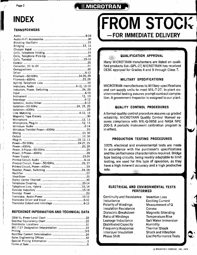
FROM STOCI~ -FOR IMMEDIATE DELIVERY
QUALIFICATION APPROVAL
Many MICROTRAN transformers are listed on qualified products Iist-QPL-27. MICROTRAN has received DESC apprQval for Grades 4 and 5 through Class T.
MILITARY SPECIFICATIONS
MICROTRAN manufactures to Military specifications and can'·supply units to meet MIL-T-27. In-plant environmental testing assures prompt contract completion. A government inspector is assigned to our plant.
QUALITY CONTROL PROCEDURES
A formalquality control procedure assures up graded reliability. MICROTRAN Quality Control Manual assures compliance with MIL-Q-9858 and NASA NPC 200-3. A periodic instrument calibration program is in effect.
PRODUCTION TESTING PROCEDURES
100% electrical and environmental tests are made in accordance with the purchaser's specifications and the performance characteristics required. Bridge type testing circuits, being readily adaptable to limit testing, are used for this type of operation, as they have a high inherent accuracy and a high productive rate.
ELECTRICAL AND ENVIRONMENTAL TESTS PERFORMED
Continuity and Resistance Inductance Polarity of Windings Insulation Resistance Dielectric Breakdown Ratio of Windings Leakage Inductance Distributed Capacity Frequency Response Interlayer Insulation Phase Shift
Insertion Loss Exciting Current Measurement of Q Corona Magnetic Shielding Temperature Rise Salt Water Immersion Humidity Thermal Shock Shock and Vibration End Performance Tests
© MICROTRAN COMPANY, INC. 1974

I
~ I '
Page 3
t .................................................................... ...
Q. MICROTRAN maintains a warehouse stock of all catalog transformers. This provides immediate availability for your design requirements. From breadboard to prototype, from pilot to production run-Microtran catalog, custom design and built to order transformers are your assurance of quality, performance and on-time production schedules. Catalog items are available off-the-shelf from stocking distributors listed on page 31.
NET PRICE LIST Net Net
Part Page Price Part Page Price Number No. 1·9 Pcs. Number No. 1·9 P"cs.
DCM1·PC ........ 12 4.95 M7·CMt .......... 10 *15.15 DCM2·PC ........ 12 5.10 M7·FB ............ 10 6.00 DCM3·PC ........ 12 4.80 M7·H .............. 10 9.90 DCM4·PC ........ 12 4.95 M7·M .............. 10 10.65 DCM5·PC ........ 12 4.95 M7·P .............. 10 10.95 DCM6·PC ........ 12 4.80 M7·PC ............ 10 6.00 DCM7·PC ........ 12 5.25 M8·A .............. 10 10.65 DCM8·PC ........ 12 4.50 M8·AG ............ 10 12.45 DCM9·PC ........ 12 4.50 M8·CMt .......... 10 *16.20 DCM10·PC ...... 12 4.80 M8·FB ............ 10 6.90 DCM11·PC ...... 12 4.50 M8·H .............. 10 11.40 DCM12·PC ...... 12 4.80 M8·M .............. 10 11.25 DCM 13·PC ...... 12 4.35 M8·P .............. 10 11.85 DCM14·PC ...... 12 4.20 M9·A .............. 10 10.65 DCM18·PC ...... 12 5.25 M9·AG ............ 10 12.15
4.80 * 16.20
PRICES, MECHANICAL CONSTRUCTION OR ELECTRICAL CHARACTERISTICS SUBJECT TO MOOIFICATION WITHOUT NOTICE- EFFECTIVE 7/1/74
Net Net Net Part Page Price Part Page Price Part Page Price
Number No. 1·9 Pcs. Number No. 1·9 Pcs. Number No. 1·9 Pcs.
M8023 ............ 24 37.80 M8ll6 ............ 21 34.20 MMT4·FB ........ 8 5.70 M8024 ............ 24 31.80 M8117 ............ 21 23.55 MMT4·H ........ 8 9.90 M8025 ............ 12 16.50 M8ll8 ............ 21 33.00 MMT4·M ........ 8 9.75 M8026 ............ 12 16.50 M8120 ............ 21 9.15 MMT5·CMt .... 8 *11.85 M8027 ............ 12 12.30 M8121 ............ 21 7.80 MMT5·FB ... ". 8 4.80
M8030 ............ 12 19.50 M8122 ............ 21 19.65 MMT5·H ........ 8 8.40 M8031 ............ 12 20.40 M8132 ............ 21 21.30 MMT5·M ........ 8 9.15
M8032 ............ 12 18.45 M8133 ............ 21 21.15 MMT7·CMt .... 8 *12.45
M8033 ............ 12 18.45 M8149 ............ 21 8.10 MMT7·FB ........ 8 5.10
M8034t .......... 21 *34.20 M8151 ............ 24 25.65 MMT7·H ........ 8 9.00
M8035t .......... 21 *34.20 M8152 ............ 24 17.40 MMT7·M ........ 8 9.60
M8036t .......... 21 *32.10 M8198 ............ 24 4.80 MMT8·CMt .... 8 *12.75
M8038 ............ 23 21.30 M8199 ............ 24 5.40 MMT8'FB ...... 8 5.70
M8039 ............ 23 19.65 M8200 ............ 24 6.75 MMT8·H ........ 8 9.90
M8041 ............ 23 13.95 M8201 ............ 24 7.35 MMT8·M ... ".0' 8 9.75
M8042 ............ 24 17.25 M8202 ............ 24 11.70 MMT9·CMt .... 8 *11.55
Part Page Number No.
MMT31·H ...... 8 MMT31·M . ..... 8 MMT32·CMt .. 8 MMT32·FB ...... 8 MMT32·H ...... 8 MMT32·M ...... 8 MMT33·CMt .. 8 MMT33·FB ...... 8 MMT33·H ...... 8 MMT33·M . ..... 8 MMT35·CMt .. 8 MMT35·FB ...... 8 MMT35·H . ..... 8 MMT35·M . ..... 8 MTl·A ............ 10 MTl·AG .......... 10
Net Price
1·9 Pcs.
9.15 9.45
*12.75 5.25 9.75 9.75
*12.75 5.25 9.75 9.75
*12.90 5.40 9.90 9.90 8.10 8.70 DCM19·PC ...... 12 M9·CMt .......... 10
DCM20·PC ...... 12 4.05 M9·FB ............ 10 6.60 M8043 ............ 24 22.80 M8203 ............ 24 14.85 MMT9·FB ...... 8 5.10 MTl·CMt ........ 10 *14.10
DCM21·PC ...... 12 4.05 M9·H .............. 10 11.10 M8044 ............ 24 29.10 M8204 ............ 24 12.60 MMT9·H ........ 8 9.30 MTl·FB .......... 10 4.65
DCM22·PC ...... 12 4.05 M9·M .............. 10 11.25 M8045 ............ 24 25.50 M8205 ............ 24 19.65 MMT9·M ........ 8 8.85 MTl·H ............ 10 8.25
DCM51·PC ...... 12 3.60 M9·P .............. 10 11.55 M8046 ............ 24 39.60 M8222 ............ 25 13.20 MMTlO·CMt .. 8 *10.95 MTl·M ............ 10 9.00
DCM52·PC ...... 12 3.30 M10·A ............ 10 11.40 M8050 ............ 21 7.35 M8223 ............ 25 18.90 MMTlO·FB ...... 8 4.95 MTl·P ............ 10 9.60
DCM53·PC ...... 12 3.15 MlO·AG .......... 10 13.35 M8051 ............ 21 13.50 M8224 ............ 25 15.75 MMTlO·H ........ 8 8.55 MTl·PC .......... 10 4.65
HD·11·AD ........ 30 ~ 4.25 MlO·CMt ........ 10 * 16.35 M8052 ............ 12 15.60 M8242 ............ 25 7.65 MMTlO·M ...... 8 8.40 MT2·A ............ 10 9.00
HD·11M .......... 30 ~39.95 MlO·FB .......... 10 7.35 M8053 ............ 12 15.60 M8243 ............ 25 9.00 MMTl1·CMt .. 8 *11.70 MT2·AG .......... 10 10.80
HD·15 ............ 30 ~ 13.99 MlO·H ............ 10 12.15 M8055 ............ 24 27.60 M8244 ............ 25 12.00 MMTl1·FB .... 8 5.10 MT2·CMt ........ 10 *15.45
HD·20 ............ 30 ~ 75.00 M10·M ............ 10 11.85 M8056 ............ 24 36.00 M8245 ............ 25 9.60 MMTl1·H ...... 8 9.30 MT2·FB .......... 10 5.25
HD'25 ............ 30~165.00 M10·P ............ 10 10.35 M8058 ............ 23 11.85 M8246 ........... 25 19.65 MMTl1·M "", . 8 9.00 MT2·H ............ 10 9.75
HD·35M .......... 30 ~32.00 Mll·A ............ 10 10.65 M8059 ............ 23 20.85 M8247 ............ 25 17.40 MMTl2·CMt .. 8 *11.10 MT2·M ............ 10 9.90
HD·40M .......... 30 ~ 7.49 M11·AG .......... 10 12.60 M8060 ............ 23 33.60 M8251 ............ 25 13.20 MMTl2·FB .... 8 4.35 MT2·P ............ 10 10.20
HM·90 ............ 30 ~ 11.95 Mll·CMt ........ 10 * 16.35 M8061 ............ 23 58.50 M8255 ............ 25 14.55 MMTl2·H ...... 8 7.95 MT3·A ............ 10 8.70
Hp·61 ............ 30 ~ 6.15 Mll·FB .......... 10 7.05 M8062 ............ 23 69.60 M8256 ............ 25 15.45 MMTl2·M ...... 8 8.55 MT3·AG .......... 10 9.30
Hp·70 ............ 30 ~10.50 Mll·H ............ 10 11.55 M8063 ............ 23 10.50 M8278 ............ 25 20.70 MMTl3·CMt .. 8 *11.25 MT3·CMt ........ 10 *15.00
M1·A .............. 10 10.65 Mll·M ............ 10 10.80 M8064 ............ 23 13.65 M8286 ............ 25 10.95 MMTl3·FB ...... 8 4.65 MT3·FB .......... 10 4.95
M1·AG ............ 10 12.60 Mll·P ............ 10 12.00 M8065 ............ 23 25.95 M8287 ............ 25 10.95 MMT13·H ...... 8 8.55 MT3·H ............ 10 8.40
Ml-CMt .......... 10 *15.45 M12·A ............ 10 10.05 M8066 ............ 23 36.00 M8288 ............ 25 12.15 MMTl3·M ...... 8 8.70 MT3·M ............ 10 9.60
Ml-FB ............ 10 7.05 M12·AG .......... 10 11.85 M8067 ............ 23 29.10 M8289 ............ 25 9.00 MMT16·CMt .. 8 * 12.45 MT3·P ............ 10 9.90
M1·H .............. 10 11.55 M12·CMt ........ 10 *16.35 M8068 ............ 23 17.10 M8290 ............ 25 8.70 MMTl6·FB ...... 8 5.10 MT3·PC .......... 10 4.95
M1·M .............. 10 10.80 M12·FB .......... 10 5.85 M8069 ............ 23 9.75 M8291 ............ 25 10.95 MMTl6·H ...... 8 9.00 MT5·A ........... 10 8.70
M1·P .............. 10 12.00 M12·H ............ 10 10.50 M8070 ............ 23 14.85 M8294 ............ 25 6.15 MMTl6·M ...... 8 9.60 MT5·AG .......... 10 9.30
M1·S ........ 10.12 14.25 M12·M ............ 10 10.80 M8071 ............ 23 32.10 M8295 ............ 25 13.20 MMTl7·CMt .. 8 *12.15 MT5·CMt ........ 10 *15.00
M2·A .............. 10 11.25 M12·P ............ 10 10.95 M8072 ............ 21 9.15 M8296 ............ 25 13.80 MMTl7·FB ...... 8 5.25 MT5·FB .......... 10 4.95
M2·AG ............ 10 13.50 M13·A ............ 10 8.40 M8073 ............ 21 5.70 M8525t ....... , .. 12 *16.65 MMTl7·H ...... 8 9.45 MT5·H ............ 10 8.40
M2·CMt .......... 10 *15.90 M13·AG .......... 10 9.00 M8074 ............ 21 6.30 M8526t .......... 12 *16.65 MMTl7·M 8 9.30 MT5·M ............ 10 9.60
MUB ............ 10 7.50 M13·CMt ........ 10 *12.75 M8075 ............ 23 9.75 M8552t .......... 12 *17.10 MMTl8·CMt .. 8 *12.75 MT5·P ............ 10 9.90
M2·H .............. 10 12.30 M13·FB .......... 10 4.65 M8076 ............ 23 13.65 M8553t ......... 12 *16.50 MMTl8·FB ...... 8 5.40 MT5·PC .......... 10 4.95
M2·M .............. 10 11.10 M13·H ............ 10 8.70 M8077 ............ 23 31.80 MM1·CMt 8 *11.10 MMTl8·H ...... 8 9.60 MT6·A ............ 10 9.45
M2·P .............. 10 12.45 M13·M ............ 10 8.85 M8078 ............ 24 38.70 MM1·FB .......... 8 6.15 MMTl8·M ...... 8 9.75 MT6·AG .......... 10 10.35
M3·A .............. 10 10.20 M13·P ............ 10 9.60 M8079 ............ 23 31.50 MM1·H ............ 8 9.75 MMTl9·CMt .. 8 * 11.25 MT6·CMt ........ 10 *15.15
M3·AG ............ 10 11.40 M13·PC .......... 10 4.65 M8080 ............ 23 17.25 MM1·M 8 8.55 MMTl9·FB ...... 8 4.95 MT6·FB .......... 10 5.70
M3·CMt .......... 10 *15.15 M14·A ............ 10 9.45 M8081 ............ 23 9.75 MM2·CMt 8 *11.25 MMTl9·H ...... 8 8.85 MT6·H ............ 10 9.60
M3·FB ............ 10 6.75 M14·AG .......... 10 10.80 M8082 ............ 23 10.50 MM2·FB .......... 8 6.30 MMTl9·M 8 8.70 MT6·M ............ 10 9.75
M3·H .............. 10 10.50 M14·CMt ........ 10 *15.90 M8083 ............ 23 21.30 MM2·H .......... 8 9.90 MMT21·CMt .. 8 *12.75 MT6·P ............ 10 10.65
M3·M .............. 10 10.65 M14·FB .......... 10 5.85 M8084 ............ 23 16.50 MM2·M .......... 8 8.70 MMT21·FB ...... 8 5.40 MT6·PC .......... 10 5.70
M3·P .............. 10 11.70 M14·H ............ 10 10.50 M8085 ............ 23 36.30 MM3·CMt 8 *10.95 MMT21·H ...... 8 9.90 MT7·A ............ 10 8.85
M3·PC ............ 10 6.75 M14·M ............ 10 11.10 M8086 ............ 24 26.85 MM3·FB .......... 8 5.85 MMT21·M ...... 8 9.75 MT7·AG .......... 10 9.90
M4·A .............. 10 9.15 M14·P ............ 10 10.80 M8087 ............ 24 27.15 MM3·H ........... 8 9.45 MMT25·CMt .. 8 *11.70 MT7·CMt ........ 10 *15.15
M4·AG ............ 10 10.20 M14·PC .......... 10 5.85 M8088 ............ 24 26.40 MM3·M 8 8.40 MMT25·FB ...... 8 5.10 MT7·FB .......... 10 5.25
M4·CMt .......... 10 *13.35 M15·A ............ 10 9.45 M8089 ............ 24 17.55 MM4·CMt 8 *10.80 MMT25·H ...... 8 9.30 MT7·H ............ 10 9.15
M4·FB ............ 10 6.00 M15·AG .......... 10 10.20 M8090 ............ 24 23.40 MM4·FB .......... 8 5.55 MMT25·M ...... 8 9.00 MT7·M ............ 10 9.75
M4·H .............. 10 9.60 M15·CMt ........ 10 *14.55 M8091 ............ 24 25.50 MM4·H ............ 8 9.15 MMT26·CMt .. 8 * 11.55 MT7·P ............ 10 10.20
M4·M .............. 10 9.45 M15·FB .......... 10 5.85 M8094 ............ 24 14.10 MM4·M 8 8.25 MMT26·FB ...... 8 4.95 MT8·A ............ 10 9.60
M4·P .............. 10 10.95 M15·H ............ 10 9.90 M8095 ............ 24 31.80 MM5·CMt ...... 8 *10.50 MMT26·H ., .... 8 9.15 MT8·AG .......... 10 10.80
M4·PC ............ 10 6.00 M15·M ............ 10 10.50 M8096 ............ 24 31.80 MM5·FB ........ 8 5.55 MMT26·M . ..... 8 8.85 MT8·CMt ........ 10 * 15.45
M5·A .............. 10 9.30 M15·P ............ 10 1O.8u M8098 ............ 24 11.25 MM5·H .......... 8 8.85 MMT27·CMt .. 8 *11.55 MT8·FB .......... 10 5.70
M5-AG ............ 10 9.30 M15·PC .......... 10 5.85 M8099 ............ 24 12.90 MM5·M 8 8.10 MMT27·FB ...... 8 5.40 MT8·H ............ 10 9.90
M5-CMt .......... 10 * 13.35 M·90 .............. 10 1.65 M8100 ............ 24 16.20 MM6·CMt ...... 8 *10.95 MMT27·H .. .... 8 9.60 MT8·M ............ 10 9.90
M5·FB ............ 10 5.70 M1550 ............ 25 134.70 M8101 ............ 24 20.40 MM6·FB 8 5.85 MMT27·M ...... 8 9.60 MT8·P ............ 10 10.65
M5·H .............. 10 9.00 M1551 ............ 25 39.60 M8102 ............ 24 24.60 MM6·H ............ 8 9.45 MMT28·CMt .. 8 *12.75 MT8·PC .......... 10 5.70
M5·M .............. 10 9.30 M1552 ............ 25 11.85 M8103 ............ 24 28.50 MM6·M .......... 8 8.40 MMT28·FB ...... 8 5.25 MT9·A ............ 10 9.00
M5·P .............. 10 10.65 M1553 ............ 25 17.25 M8l04 ............ 24 24.90 MM7·CMt ...... 8 *9.90 MMT28·H . ..... 8 9.45 MT9·AG .......... 10 10.35
M5·PC ............ 10 5.70 M1554 ............ 25 64.80 M8l05 ............ 24 30.90 MM7·FB ........ 8 5.40 MMT28·M 8 9.75 MT9·CMt ........ 10 *15.45
M6·A .............. 10 10.20 M1555 ............ 25 23.55 M8106 ............ 23 18.30 MM7·H .......... 8 9.00 MMT29·CMt .. 8 * 12.75 MT9·FB .......... 10 5.25
M6·AG ............ 10 10.95 M1556 ............ 25 15.30 M8107 ............ 23 18.75 MM7·M .......... 8 7.65 MMT29·FB ...... 8 5.40 MT9·H ............ 10 9.45
M6·CMt .......... 10 * 13.20 M1557 ............ 25 54.75 M8108 ............ 23 18.45 MMTl·CMt .... 8 *11.10 MMT29·H .. .... 8 9.60 MT9·M ............ 10 9.90
M6·FB ............ 10 6.30 Ml558 ............ 25 33.60 M8109 ............ 23 18.90 MMTl·FB ...... 8 4.35 MMT29·M .. .... 8 9.75 MT9·P ............ 10 10.20
MG·H .............. 10 10.05 M1559 ............ 25 27.60 M8ll0 ............ 23 18.60 MMTl·H ........ 8 7.95 MMT30·CMt .. 8 *12.45 MT9·PC .......... 10 5.25
M6·M .............. 10 10.35 M8018 ............ 23 22.80 M8111 ............ 23 19.05 MMTl·M ........ 8 8.55 MMT30·FB ...... 8 5.10 MTlO·A .......... 10 8.70
M6·P .............. 10 11.25 M8019 ............ 23 26.10 M8112 ............ 12 15.00 MMT3·CMt .... 8 *11.25 MMT30·H .. .... 8 9.30 MTlO·AG ........ 10 9.30
M6·PC ............ 10 6.30 M8020 ............ 23 32.10 M8113 ............ 21 34.20 MMT3·FB ........ 8 4.80 MMT30·M ...... 8 9.60 MTlO·CMt ...... 10 *15.00
M7·A .............. 10 10.20 M8021 ............ 23 31.50 M8ll4 ............ 21 33.00 MMT3·H .......... 8 8.40 MMT31·CMt .. 8 *12.30 MTlO·FB ........ 10 4.65
M7·AG ............ 10 10.65 M8022 ............ 24 33.00 M8ll5 ............ 21 23.55 MMT3·M ........ 8 8.70 MMT31·FB ...... 8 4.95 MTlO·H .......... 10 8.40
*Not stocked. Available on short order. In 1·249 quantity. add $25.00 lot set·up charge. tNot stocked. Available on short order. i'.Standard discounts do not apply.

Page 4
N~ N~ N~ N~ Page Price Part Page Price Part Page Price Part Page Price Part
Number
Net Page Price No. 1·9 Pes.
Net Page Price No. 1·9 Pes.
Part Number No. 1·9 Pes. Number No. 1·9 Pes. Number No. 1·9 Pes. Number No. 1·9 Pes.
--~~~~~~i-~~--~~~~~~--~~~~~~--~~~~~--~~~4-~~~~~~~ MTlO·M .......... 10 9.60 MT26.FB .•...... 10 5.25 PC6714 .......... 27 6.60 QGL50·Ht ...... 16 *11.70 QKL5·M .......... 18 6.90 QPL7500·M .... 19 14.55
Part Number
MTlO·P ........ 10 9.60 MT26.H .......... 10 9.45 PC6715 .......... 26 6.15 QGL50·HCt .... 16 *11.70 QKLlO·F ........ 18 4.50 QPLlOOOO·F .. 19 11.10 MT11·A .......... 10 9.00 MT26.M .......... 10 10.65 PC6716 .......... 26 6.15 QGL50·M ........ 16 9.00 QKLlO·H ........ 18 7.80 QPLlOOOO·H .. 19 18.45 MTll·AG ........ 10 10.35 MT26.P .......... 10 10.20 PC6724 .......... 26 6.30 QGLI00·F ........ 16 5.85 QKLlO·M ........ 18 6.90 QPLlOOOO·M .. 19 14.85 MTll·CMt ...... 10 *15.45 MT26.PC ........ 10 5.25 PC6728 .......... 26 6.30 QGLlOO·Ht .... 16 *12.00 QKLl5·F ........ 18 4.80 QPLl5000·F .. 19 12.00 MTll·FB ........ 10 5.25 MT29.A .......... 10 8.70 PC6732 .......... 26 6.30 QGLlOO·HCt .. 16 *12.00 QKLI5·H ........ 18 7.95 QPLl5000·H .. 19 19.80 MTll·H .......... 10 9.45 MT29.AG ........ 10 9.30 PC6905 .......... 27 8.10 QGLlOO·M ...... 16 9.45 QKLl5·M ........ 18 6.90 QPLl5000·M .. 19 15.60 MTll.M .......... 10 9.90 MT29.CMt ...... 10 *15.00 PC6910 .......... 27 8.10 QGL250·F ........ 16 6.60 QKL25·F ........ 18 4.95 QPL25000·F .. 19 13.05 MT11.P .......... 10 10.20 MT29.FB ........ 10 4.35 PC6911 .......... 27 8.10 QGL250·Ht .... 16 *12.45 QKL25·H ........ 18 8.10 QPL25000·H .. 19 21.60 MT11·PC ........ 10 5.25 MT29.H .......... 10 8.40 PC6914 .......... 27 8.10 QGL250·HCt .. 16 *12.45 QKL25·M ..... : .. 18 7.05 QPL25000·M .. 19 17.40 MTl2.A .......... 10 8.70 MT29.M ......... 10 9.60 PCL6605 ........ 27 8.40 QGL250·M ..... 16 9.90 QKL50·F ........ 18 4.95 QTL25·F ........ 19 11.85 MTl2·AG ........ 10 9.30 MT29.P .......... 10 9.30 PCL6610 ........ 27 8.40 QGL500·F ...... 16 7.05 QKL50·H ........ 18 8.40 QTL25·H ........ 19 18.90 MTl2.CMt ...... 10 *15.00 MT29·PC ........ 10 4.35 PCL6611 ........ 27 8.40 QGL500·Ht .... 16 *12.90 QKL50·M ........ 18 7.05 QTl25·M ........ 19 14.55 MTl2·FB ........ 10 4.05 MT30.A .......... 10 8.70 PCL6614 ........ 27 8.40 QGL500·HCt .16 *12.90 QKLlOO·F ...... 18 5.10 QTL50·F ........ 19 12.00 MTl2.H .......... 10 8.40 MT30.AG ........ 10 9.30 PCL6630 ........ 27 8.7u QGL500·M ...... 16 10.35 QKLlOO·H ...... 18 9.00 QTL50·H ........ 19 19.20 MTl2.M .......... 10 9.60 MT30.CMt ...... 10 *15.00 PCL6631 ........ 27 8.70 QGLlOOO·F .... 16 8.55 QKLlOO·M ...... 18 7.50 QTL50·M ........ 19 14.70 MTl2.P .......... 10 9.00 MT30.FB ........ 10 4.35 PCT6230 ........ 27 8.05 QGLI000-Ht .. 16 *14.40 QKLl50·F ...... 18 5.25 QTLlOO·F ...... 19 12.45 MTl2.PC ........ 10 4.05 MT30.H .......... 10 8.40 PCT6530 ........ 27 6.90 QGLlOOO·HCt 16 *14.40 QKLl50·H ...... 18 9.15 QTL100·H ...... 19 19.50 MT13.A .......... 10 8.85 MT30.M .......... 10 9.60 PCT6531 ........ 27 6.90 QGLI000·M .... 16 11.85 QKLl50·M ...... 18 7.65 QTLlOO·M ...... 19 15.00 MT13.AG ........ 10 9.45 MT30.P .......... 10 9.30 PCT6630 ........ 27 6.90 QGL1500·F .... 16 10.50 QKL250·F ...... 18 5.25 QTLl50·F ...... 19 12.90 MTl3.CMt ...... 10 *15.15 MT30.PC ........ 10 4.35 PCT6631 ........ 27 6.90 QGLl500·Ht .. 16 *16.50 QKL250·H ...... 18 9.45 QTLl50·H ...... 19 19.95 MTl3.FB ........ 10 4.50 MT33.A .......... 10 10.20 PCT6730 ........ 27 7.05 QGLl500·Hct 16 *16.50 QKL250·M ...... 18 7.80 QTLl50·M ...... 19 15.75 MTl3.H .......... 10 8.55 MT33.AG ........ 10 12.00 PCT6731 ........ 27 7.05 QGLl500·M .... 16 13.95 QKL50Q·F ...... 18 5.40 QTL250·F ...... 19 13.20 MTl3.M .......... 10 9.75 MT33.CMt ...... 10 *15.90 PCT6930 ........ 27 8.55 QGMl·F .......... 16 5.40 QKl500·H ...... 18 9.75 QTl250·H ...... 19 20.25 MTl3.P .......... 10 9.45 MT33.FB ........ 10 6.00 PCT6931 ........ 27 8.55 QGMl·Ht ........ 16 *10.80 QKl500·M ...... 18 7.95 QTl250·M ...... 19 16.05 MTl4.A .......... 10 8.10 MT33.H .......... 10 10.80 PM3·M ............ 6 12.30 QGMl·HCt ...... 16 *10.80 QKLlOOO·F .... 18 5.55 QTl500·F ...... 19 13.50 MTl4.AG ........ 10 8.70 MT33.M .......... 10 10.20 PM5·M ............ 6 11.40 QGMl·M ........ 16 8.70 QKLlOOO·H .... 18 10.20 QTL500·H ...... 19 20.55 MTl4.CMt ...... 10 *13.95 MT33.P .......... 10 10.95 PM7·M ............ 6 12.00 QGM2·F .......... 16 5.55 QKLlOOO·M .... 18 8.40 QTl500·M ...... 19 16.05 MTl4.FB ........ 10 4.05 MT33.PC ........ 10 6.60 PM9·M ............ 6 12.00 QGM2·Ht ........ 16 *10.95 QKLl500·F .... 18 5.70 QTLlOOO·F .... 19 13.50 MTl4.H .......... 10 7.80 MT34.A .......... 10 10.05 PM11·M .......... 6 11.40 QGM2·HCt ..... 16 *10.95 QKLl500·H .... 18 10.65 QTLlOOO·H .... 19 20.85 MTl4.M ......... 10 9.00 MT34.AG ........ 10 11.85 PM13·M .......... 6 11.40 QGM2·M ........ 16 8.85 QKLl500·M .... 18 8.55 QTLlOOO·M .... 19 13.95 MTl4.P .......... 10 9.00 MT34.CMt ...... 10 *16.05 PMI5·F .......... 6 5.70 QGM5·F .......... 16 5.85 QKl2500·F .... 18 6.30 QTLl500·F .... 19 13.65 MTl4.PC ........ 10 4.05 MT34.FB ........ 10 5.85 PMI5·M .......... 6 10.50 QGM5·Ht ....... 16 *11.25 QKL2500·H .... 18 10.95 QTLI500·H .... 19 21.15 MTl5.A .......... 10 8.70 MT34.H .......... 10 10.65 PMI7·M .......... 6 10.95 QGM5·HCt ...... 16 *11.25 QKL2500·M .... 18 8.70 QTLl500·M .... 19 16.35 MTl5.AG ........ 10 9.30 MT34.M .......... 10 10.35 P1VI19·M .......... 6 11.25 QGM5·M ........ 16 9.15 QKl5000·F .... 18 7.05 QTl2500·F .... 19 14.40 MTl5.CMt ...... 10 *15.00 MT34.P .......... 10 10.80 PM21·M .......... 6 11.70 QGMI0·F ........ 16 6.00 QKl5000·H .... 18 12.00 QTl2500·H .... 19 21.90 MTl5.FB ........ 10 4.35 MT35.A .......... 10 10.80 PM23·M .......... 6 11.25 QGMI0·Ht ...... 16 *11.40 QKl5000·M .... 18 9.60 QTL2500·M .... 19 17.10 MT15.H .......... 10 8.40 MT35.AG ........ 10 12.60 PM25·M ......... 6 11.55 QGMI0·HCt .... 16 *11.40 QKllOOOO·F .18 7.80 QTl5000·F .... 19 14.40 MT15.M .......... 10 9.60 MT35.CMt ...... 10 *16.60 PM27·F .......... 6 5.55 QGM10·M ...... 16 9.30 QKllOOOO·H .. 18 13.35 QTl5000·H .... 19 22.80 MTl5.P .......... 10 9.30 MT35-FB ........ 10 6.60 PM27·M .......... 6 10.20 QGM15·F ........ 16 6.15 QKllOOOO·M .. 18 10.95 QTl5000·M .... 19 17.25 MTl8.A .......... 10 9.60 MT35.H .......... 10 11.40 PM29·M .......... 6 11.10 QGM15·Ht ...... 16 *11.55 QKM2·F .......... 18 5.10 QTllOOOO·F .. 19 15.75 MTl8.AG ........ 10 10.80 MT35.M .......... 10 10.95 PM31·F .......... 6 7.05 QGM15·HCt .... 16 *11.55 QKM2·H .......... 18 8.70 QTllOOOO·H .. 19 23.25 MTl8.CMt ...... 10 *15.45 MT35.P .......... 10 11.55 PM31·M .......... 6 10.65 QGMI5·M ...... 16 9.45 QKM2·M ........ 18 7.50 QTllOOOO·M .. 19 18.60 MTl8.FB ........ 10 5.70 MT35.PC ........ 10 7.20 PM33·F .......... 6 5.25 QGM25·F ........ 16 6.45 QKM5·F .......... 18 5.25 QT1l5000·F .. 19 16.80 MTl8.H .......... 10 9.90 PC2506 .......... 26 7.35 PM33·M .......... 6 10.50 QGM25·Ht ...... 16 *11.70 QKM5·H .......... 18 8.85 QTLl5000·H .. 19 24.15 MTl8.M .......... 10 9.90 PC2512 .......... 26 7.65 PM34·F .......... 6 5.85 QGM25·HCt .... 16 *11.70 QKM5-M ........ 18 7.50 QTl15000·M .. 19 19.80 MTl8·P .......... 10 10.65 PC2524 .......... 26 7.80 PM34·M .......... 6 10.80 QGM25·M ...... 16 9.75 QKMI0·F ........ 18 5.25 QTl25000·F .. 19 18.00 MT20.A .......... 10 9.75 PC2528 .......... 26 7.80 PM35·F .......... 6 5.40 QGM50·F ........ 16 6.75 QKMI0·H ...... 18 9.00 QTl25000·H .. 19 25.20 MT20.AG ........ 10 11.25 PC2608 .......... 26 7.80 PM35·M .......... 6 10.05 QGM50·Ht ..... 16 *12.00 QKMI0·M ...... 18 7.65 QTl25000·M .. 19 21.15 MT20.CMt ...... 10 *15.90 PC2616 .......... 26 7.95 PM36·F .......... 6 6.45 QGM50·HCt .... 16 *12.00 QKM25·F ........ 18 5.40 QTL50000·F .. 19 25.20 MT20.FB ........ 10 5.70 PC2624 .......... 26 7.95 PM36·M .......... 6 11.10 QGM50·M ..... 16 10.05 QKM25·H ........ 18 9.30 QTL50000·H .. 19 33.00 MT20.H .......... 10 10.20 PC2628 .......... 26 7.95 PM37·F .......... 6 4.95 QGM100·F ...... 16 7.35 QKM25·M ...... 18 7.80 QTL50000·M .. 19 27.75 MT20.M .......... 10 10.20 PC2632 .......... 26 8.10 PM37·M .......... 6 10.35 QGMI00·Ht .... 16 *12.90 QKM50·F ........ 18 5.55 S101·S .......... 13 11.40 MT20.P .......... 10 10.65 PC2708 .......... 26 7.80 PM38·F .......... 6 5.40. QGMI00·Hct .. 16 *12.90 QKM50·H ........ 18 9.45 SI01·SP ........ 13 F.Q. MT2l.A .......... 10 9.15 PC2712 .......... 26 7.80 PM38·M .......... 6 10.95 QGMI00·M .... 16 10.35 QKM50·M ...... 18 7.95 S105·S .......... 13 13.20 MT21.AG ........ 10 11.25 PC2715 .......... 26 7.95 PM39·F .......... 6 4.50 QIL3.F .......... 17 4.20 QKM100·F ...... 18 5.70 S105·SP ........ 13 ·F.Q. MT21.CMt ...... 10 *15.75 PC2716 .......... 26 7.95 PM39·M .......... 6 9.00 QIL3.H .......... 17 8.55 QKM100·H ...... 18 9.45 S107·S .......... 13 13.95 MT21.FB ........ 10 5.70 PC2724 .......... 26 8.10 PM40·F .......... 6 4.35 QIL3·M .......... 17 7.05 QKMI00·M .... 18 8.10 SI07·SP ........ 13 F.Q. MT21.H .......... 10 10.20 PC2728 .......... 26 8.10 PM40·M .......... 6 8.55 QIL5.F ............ 17 4.20 QKM250·F ...... 18 5.85 S118·S .......... 13 11.70 MT21.M .......... 10 10.05 PC2732 .......... 26 8.25 PM41·F .......... 6 4.05 QIL5.H .......... 17 8.55 QKM250·H ...... 18 9.75 S118·SP ........ 13 F.Q. MT21.P .......... 10 10.65 PC4304 .......... 23 4.35 PM41·M .......... 6 8.10 QIL5.M .......... 17 7.05 QKM250·M .... 18 8.40 S126·S .......... 13 10.95 MT21.PC ........ 10 6.30 PC4312 .......... 23 4.50 PM90 .............. 6 1.20 QILlO·F .......... 17 4.20 QKM500·F ...... 18 6.15 SI26·SP ........ 13 F.Q. MT22.A .......... 10 9.90 PC4316 .......... 23 4.50 QELl·M .......... 15 9.45 QlllO·H ........ 17 8.55 QKM500·H ...... 18 10.05 S130·S .......... 13 11.85 MT22.AG ........ 10 11.55 PC4320 .......... 23 4.65 QEL2·M .......... 15 9.45 QlllO·M ........ 17 7.05 QKM500·M .... 18 8.70 SI30·SP ........ 13 F.Q. MT22.CMt ...... 10 *15.75 PC4408 .......... 23 4.50 QEL5·M .......... 15 9.90 QILl5·F .......... 17 4.20 QKMI000·F ... 18 6.45 S100·FB .......... 13 .21 MT22.FB ........ 10 6.00 PC4412 .......... 23 4.50 QELI0·M ........ 15 10.35 Q11l5·H ........ 17 8.55 QKMI000·H .... 18 11.10 SMl·AF .......... 9 10.65 MT22.H .......... 10 10.50 PC4416 .......... 23 4.65 QE1l5·M ........ 15 10.50 Q11l5·M ........ 17 7.20 QKM1000·M .. 18 9.90 SM1·CMt ...... 9 *11.70 MT22.M .......... 10 10.05 PC4424 .......... 23 4.65 QEL25·M ........ 15 10.65 QIL25·F ........ 17 4.35 QPl25·F ........ 19 6.90 SMl·FB .......... 9 6.45 MT22.P .......... 10 10.95 PC4428 .......... 23 4.80 QEL50·M ........ 15 11.10 QIL25·H ........ 17 8.85 QPL25·H ........ 19 15.75 SMl·H ............ 9 10.05 MT23.A .......... 10 8.70 PC4432 .......... 23 4.95 QELlOO·M ...... 15 11.25 QIL25·M ........ 17 7.20 QPL25·M ........ 19 12.15 SMl·M .......... 9 9.90 MT23.AG ........ 10 9.30 PC6205 .......... 27 7.65 QEM05·M ...... 15 10.65 QIL50·F .......... 17 4.35 QPL50·F .......... 19 7.05 SM2·AF .......... 9 10.50 MT23.CMt ...... 10 *15.00 PC6210 .......... 27 7.65 QEMl·M ........ 15 10.65 QIL50·H ........ 17 9.00 QPL50·H ........ 19 15.90 SM2·CMt· .... 9 *11.70 MT23.FB ........ 10 4.35 PC6211 ......... 27 7.65 QEM2·M ........ 15 10.95 QIL50·M ........ 17 7.35 QPL50·M ........ 19 12.30 SM2·FB .......... 9 6.30 MT23.H .......... 10 8.40 PC6214 .......... 27 7.65 QEM5·M ........ 15 11.40 QILlOO·F ........ 17 4.50 QPllOO·F ...... 19 7.20 SM2·H .......... 9 9.60 MT23.M .......... 10 9.60 PC6505 .......... 27 6.45 QEMI0·M ........ 15 11.70 QIL100.H ........ 17 9.60 QPLlOO·H ...... 19 16.05 SM2·M .......... 9 9.90 MT23·P .......... 10 9.30 PC6506 .......... 26 6.15 QEM15·M ...... 15 11.85 QlllOO·M ...... 17 7.65 QPllOO·M ...... 19 12.45 SM3·AF .......... 9 9.90 MT23·PC ........ 10 4.35 PC6510 .......... 27 6.45 QEM25·M ...... 15 12.15 QIL150·F ........ 17 4.95 QPL250·F ........ 19 7.35 SM3·CMt ...... 9 *11.70 MT24·A .......... 10 8.70 PC6511 .......... 27 6.45 QEM50·M ...... 15 12.30 QILI50·H ........ 17 9.75 QPL250·H ...... 19 16.20 SM3·FB .......... 9 5.70 MT24.AG ........ 10 9.30 PC6512 .......... 26 6.45 QGL5·F .......... 16 5.10 Q11l50·M ...... 17 7.80 QPL250·M ...... 19 12.60 SM3·H .......... 9 9.30 MT24.CMt ...... 10 *15.00 PC6514 .......... 27 6.45 QGL5·Ht ........ 16 *10.95 QIL250·F ........ 17 5.10 QPL500·F ...... 19 7.50 SM3·M .......... 9 9.90 MT24.FB ........ 10 4.35 PC6524 .......... 26 6.45 QGL5·HCt ...... 16 *10.95 QIL250·H ........ 17 9.75 QPL500·H ...... 19 16.35 SM4·AF .......... 9 10.20 MT24.H .......... 10 8.40 PC6528 .......... 26 6.60 QGL5·M .......... 16 8.40 QIL250·M ...... 17 8.25 QPL500·M ...... 19 12.75 SM4·CMt ...... 9 *11.70 MT24.M .......... 10 9.60 PC6605 .......... 27 6.60 QGLlO·F ........ 16 5.25 QIL500·F ........ 17 5.85 QPLI000·F ...... 19 7.80 SM4·FB ......... 9 6.00 MT24.P .......... 10 9.30 PC6608 .......... 26 6.30 QGLlO·Ht ...... 16 *11.25 QIL500·H ........ 17 10.65 QPLI000·H .... 19 16.65 SM4·H ............ 9 9.60 MT24.PC ........ 10 4.35 PC6610 .......... 27 6.60 QGLI0·HCt .... 16 *11.25 QIL500·M ...... 17 9.00 QPLI000·M .... 19 13.20 SM4·M .......... 9 9.90 MT25.A .......... 10 9.60 PC661] .......... 27 6.60 QGLlO·M ........ 16 8.55 QIL1000·F ...... 17 6.75 QP1l500·F .... 19 8.10 SM5·AF .......... 9 9.00 MT25.AG ........ 10 10.35 PC6614 .......... 27 6.60 QGLl5·F ........ 16 5.40 QlllOOO·H .... 17 11.55 QPLl500·H .... 19 16.95 SM5·CMt ...... 9 *10.95 MT25.CMt ...... 10 *15.45 PC6616 .......... 26 6.45 QGL15·Ht ...... 16 *11.40 QILI000·M .... 17 9.90 QPL1500·M .... 19 13.35 SM5-FB ........ 9 5.25 MT25.FB ........ 10 5.25 PC6624 .......... 26 6.45 QGL15·HCt .... 16 *11.40 QIL1500·F ...... 17 8.40 QPL2500·F .... 19 8.70 SM5·H ......... 9 8.55 MT25.H .......... 10 9.45 PC6628 .......... 26 6.45 QG1l5.M ...... 16 8.70 QILl500·H ...... 17 13.20 QPL2500·H .... 19 17.25 SM5·M .......... 9 9.30 MT25.M .......... 10 9.90 PC6632 .......... 26 6.45 QGL30.F ........ 16 5.55 QILl500·M .... 17 11.55 QPL2500·M .... 19 13.65 SM6·AF .......... 9 10.50 MT25.P .......... 10 10.20 PC6705 .......... 27 6.60 QGL30.Ht ...... 16 '11.55 QIL2500·F ...... 17 9.90 QPL5000·F .... 19 9.45 SM6·CMt ...... 9 *11.70 MT25.PC ........ 10 5.25 PC6708 .......... 26 6.15 QGL30.HCt .... 16 *11.55 QIL2500·H .... 17 14.70 QPL5000·H .... 19 17.70 SM6·FB .......... 9 6.30 MT26.A .......... 10 8.85 PC6710 .......... 27 6.60 QIL2500·M .... 17 13.20 QPL5000·M .... 19 14.10 SM6·H ............ 9 8.10 MT26.AG ........ 10 10.35 PC6711 .......... 27 6.60 QGL30·M ........ 16 8.85 QKL5·F .......... 18 4.35 QPL7500·F .... 19 10.05 SM6·M .......... 9 9.90 MT26.CMt ...... 10 *15.15 PC6712 .......... 26 6.15 QGL50·F ........ 16 5.70 QKL5·H .......... 18 7.65 QPL7500·H .... 19 18.15 SMTl·AF ........ 9 9.15
NOTE: Items with· FBR suffix (i.e. PC6608·FBR) not stocked. Available on short order in 1-49 quantity, add $10.00 lot set up charge. F.Q.: Contact factory for quote.

Net I'Irt .... e Price N.. It, ,., Pes.
SMTl-CMt .••.•• 9 *9.30 SMTl·FB ...•••.• 9 • 4.95 SMTl·H ..•......• 9 8.55 SMTl·M •....... 9 8.40 SMT3-Af •••... 9 10.05 SMT3-CMt •.•• 9 *10.20 SMT3·FB •..•.• 9 5.85 SMT3·H .••••••• 9 9.45 SMT3·M •.•.•••. 9 9.00 SMT4-CMt •.•• 9 *10.65 SMT4·FB •••••••• 9 6.60 SMT4·H ..•••••. 9 10.80 SMT4-M .•••.•.• 9 9.60 SMT5·AF ..•.•.•• 9 9.90 SMT5·CMt ...• 9 *9.90 SMT5-FB ..•...• 9 5.70 SMT5·H ••••..•••. 9 9.30 SMT5-M ••.•••.. 9 8.85 SMT7-AF ••••...• 9 10.65 SMT7-CMt •••. 9 *10.35 SMT7·FB •••••••• 9 6.00 SMT7·H •••••..• 9 9.90 SMT7·M •......• 9 9.30 SMT8-CMt ...• 9 *10.65 SMT8·FB ...•.••• 9 6.60 SMT8·H .....•.... 9 10.80 SMT8-M ••••....•• 9 9.60 SMT9·CMt •...•• 9 *9.75 SMT9·FB ..••..•• 9 5.70 SMT9·H •...•••••• 9 9.90 SMT9·M •.•••••• 9 8.70 SMTlD-AF •.••.. 9 9.90 SMTlO-CMt .. 9 *9.75 SMTlO·FB ••.... 9 5.70 SMTlD-H ..••••.. 9 9.30 SMTlO·M ...•..•. 9 8.70 SMTl2·AF •..... 9 9.15 SMTl2-CMt .. 9 *9.30 SMTl2·FB ....•. 9 4.95 SMTl2·H •.••••.. 9 8.55 SMT12·M •.•••• 9 8.40 SMTl3·AF ....•• 9 9.75 SMT13·CMt .... 9 *9.60 SMT13·FB •••..• 9 5.10 SMT13·H .....•.. '9 9.00 SMT13·M •...•... 9 8.55 SMT16-AF ...... 9 10.80 SMT16·CMt .. 9 *10.35 SMT16·FB ...... 9 6.15 SMT16·H ........ 9 10.05 SMT16·M ........ 9 9.30 SMT17-CMt .... 9 *10.50 SMT17·FB ...... 9 6.30 SMT17·H ........ 9 10.50 SMT17·M ........ 9 9.45 SMT18·CMt .... 9 *10.65 SMTl8·FB ...... 9 6.45 SMT18·H ........ 9 10.65 SMT18·M ........ 9 9.60 SMT19·AF ...... 9 10.50 SMT19-CMt .... 9 *10.35 SMT19·FB ...... 9 5.85 SMT19·H ........ 9 9.75 SMT19·M ...... 9 9.30 SMT26-CMt .. 9 *10.20 SMT26·FB ...... 9 5.55 SMT26·H ........ 9 9.75 SMT26·M ........ 9 9.00 SMT36·CMt .. 9 *10.80 SMT36·FB ...... 9 6.45 SMT36-H ........ 9 10.95 SMT36·M ........ 9 9.75 T1104 ............ 14 5.10 T2104 ............ 14 4.65 T2106 ............ 14 4.95 T2108 ............ 14 4.65 T2110 ............ 14 4.95 T2220 ............ 14 5.25 T2316 ............ 14 4.80 T3220 ............ 14 6.15 T4415 ............ 14 4.80 T6112 ............ 14 11.85 T7410 ............ 14 6.75 T8410 ............ 14 5.55 UM21-F .......... 7 6.00 UM21·M ........ 7 9.45 UM22·F .......... 7 5.10 UM22·M ........ 7 9.00 UM23·F .......... 7 5.25 UM23·M .......... 7 9.15 UM24·F .......... 7 4.50 UM24-M ........ 7 7.35 UM25-F .......... 7 4.50 UM25·M ........ 7 7.35 UM26·F .......... 7 4.50 UM26·M ........ 7 7.35 UM27·F .......... 7 4.80
Part Number
UM27·M UM28-F UM28·M UM29·F UM29·M UM30·F UM30·M UM31·F UM3l·M UM32·F UM32·M UM33·F UM33·M UM34·F UM34·M
Page
Standard Sales Policy Information
QUANTITY PRICING SCHEDULE: 1-9 Net, 10-49 Net Less 10%,50-99 Net Less 16%%,100-249 Net Less 33113%. Contact factory for quantities over 249 pieces.
STANDARD CATALOG ITEMS: Order from Authorized Distributors for immediate delivery at factory prices through 249 pieces. For larger quantities, contact factory for quotation.
FACTORY TERMS OF SALE: Net 30 F.O.B. Valley Stream, N.Y.
FACTORY MINIMUM BILLING: $35.00 net, exclusive of transportation charges. $5.00 small order handling charge if below minimum billing.
SPECIAL MARKING OF CATALOG ITEMS: If customer part number is to be added to standard marking information, add to regular O.E.M· price of standard catalog item the following amount:
1 pe. 2-4 pcs· 5-9 pcs. 10-24 pcs. 25·49 pcs. 50-99 pes. 100-249 pcs. $12.65 $6.40 $2.65 $1.39 $.64 $.38 $.23
For any other type of special marking or larger quantities, contact factory for quotation.
SPECIAL ORDER ITEMS: Transformers shown as "Special Order Only" are not normally stocked but may be ordered from Authorized Distributors. The following special order types not shown in the INDUSTRIAL O.E.M. NET PRICE LIST, are priced below: Price of -FPB type is same as equivalent -FB type (i.e. MTl-FPB is same price as MTl-FBl. Price of -F type (i.e. MTl-Fl is price of -FB type (i.e. MTl-FBl less the following amounts: Quantity 1-9-$.15; 10-49-$.14; 50-99-$.13; 100-249-$.10. For all other "SPECIAL ORDER" items not priced, contact factory for price and delivery.
CUSTOM TRANSFORMERS: Contact factory for price and delivery.
PRICING-SCHEDULED DELIVERIES: Published or quoted quantity price bracket is only applicable to those quantities scheduled by customer for delivery within a given 60 day period.
ASSORTING POLICY: Units may not be intermixed for quantity priCes. Quantity price bracket is applicable to shipments scheduled within 60 days.
GOVERNMENT SOURCE INSPECTION: Increase unit price by $.10, or a minimum of $25.00 per scheduled shipment, to cover documentation cost.
PLACE OF ACCEPTANCE: Factory orders are valid only when accepted by MICROTRAN'S written acknowledgment at its offices in Valley Stream, New York. The contract shall be construed in accordance with New York State law.
D C No. 789052 D-U-N-S 203-7224 F.S.C.: 00348
Net Net Net Net Price Part Page Price Part Page Price Part Page Price
No. ,.g Pcs. Number No. ,.g Pcs. Number No. ,.g Pcs. Number No. ,.g Pcs.
.......... 7 7.80 UM35·F .......... 7 5.70 VM4·FPB ........ 7 5.70 VMll·M ........ 7 6.90 .......... 7 3.75 UM35·M .. ...... 7 10.95 VM4·M .......... 7 8.70 VM12·FPB ...... 7 5.10 ........ 7 6.60 UM36·F . ......... 7 5.55 VM5·FPB ........ 7 5.25 VM12·M ........ 7 8.10
.......... 7 5.25 UM36·M . ....... 7 10.95 VM5·M .......... 7 8.25 VM13·FPB ...... 7 5.25 ........ 7 8.25 UM37·F ........ - 7 5.25 VM6·FPB ........ 7 5.85 VM13·M ........ 7 8.40
.......... 7 3.60 UM37·M . ...... , 7 8.85 VM6·M .......... 7 8.85 VM14·FPB ...... 7 4.95 ........ 7 6.30 UM39·F .. ........ 7 5.25 VM7·FPB .. ...... 7 4.20 VM14·M ........ 7 8.25
.......... 7 5.55 UM39·M . ....... 7 8.55 VM7·M .......... 7 7.50 VM15·FPB . ..... 7 6.00 ........ 7 10.35 UM90 ............ 7 1.35 VM8·FPB . ....... 7 4.35 VM15·M .. ...... 7 9.75
.......... 7 5.40 VM1·FPB . ....... 7 4.20 VM8·M .......... 7 7.50 VM16·FPB 7 4.50 7 8.40 VM1·M 7 7.20 VM9·FPB 7 4.35
.. .... ........ .......... ........
VM16·M 7 8.25 .......... 7 5.25 VM2·FPB . ....... 7 5.70 VM9·M 7 7.50 ........ . " ..... 7 8.25 VM2·M .......... 7 8.70 VMlO·FPB ...... 7 5.25 VM17·FPB ...... 7 5.85
.......... 7 5.55 VM3·FPB .. ...... 7 5.10 VMlO·M ........ 7 8.40 VM17·M ........ 7 8.70
........ 7 10.35 VM3·M . ......... 7 8.10 VMll·FPB ...... 7 4.05 VM90 .............. 7 1.95
Page 5
*Not stocked. Available on short order. In 1·249 quantity, add $25.00 lot set·up charge. tNot stocked. Available on short order. ["standard discounts do not apply.

Page 6 ~ Mool f41t3 it.; i ill' ~ ;) PICO MINIATURE TRANSFORMERS
Pico Miniature Transformers - PM Series - are designed to provide maximum utilization of space in miniaturized printed circuit board applications .. 10 grid dimensions conform to P.C. design standards. Installation of these units is accomplished without the additional use of brackets or clips. Manufactured in accordance with the requirements of MIL-T-27.
FULL TERMINAL ARRANGEMENTS AND CDLOR CODE DESIGNATIONS SUPPLIED WITH EACH UNIT.
PICO MINIATURE TRANSFORMERS - PM SERIES Frequency Response ± 2 db 300 Hz to 100 KHzt
These units can be used as input, interstage, output, isolation and other impedance requirements. Primary and secondary windings may be interchanged to obtain required impedance matching. Note: This will result in slightly different impedance ratios than shown.
Unbal. Power Pri.
DC Ma Pri. Sec. Level tt
D.C.R. D.C.R. MW. Family Part No. Primary Secondary
Impedance Impedance
PM37-(*) 120 C.T. 3.2 10 16 0.75 50. 17
PM38-(*) 300 C.T. 600 7 41 98 50 17
500 50 3 60 8 50 17
PM36-(*) 500 500/125 Split 3 72 85 50 17
600 C.T. 600 C.T. 3 75 105 50 17
PM33-(*) 1,500 C.T. 600 3 170 95 50 12
PM31-(*) 2,500 2,500 C.T. 1 250 325 50 12
• PM29(*) 10,000 C.T. 500 C.T. 1 1050 80 50 12
PM27(*) 10,000 1,200 0.5 1050 280 50 12
• PM23(*) 10,000C.T. 1,200 C.T. 1 1050 280 50 12
• PM25(*) 10,000 1200/300 Split 0.5 1050 280 50 12
• PM19(*) 10,000 C.T. 2,000 C.T. 1000 300 50 12
• PM21(*) 10,000 2000/500 Split 0.5 1000 300 50 12
• PM17(*) 10,000 C.T. 10,000 C.T. 1 1000 1300 50 12
PM15(*) 25,000 1,000 0.25 1700 110 40 12
• PM11(*) 25,OOOC.T. 1,000 C.T. 0.5 1700 110 40 12
• PM13(*) 25,000 1000/250 Split 0.25 1700 110 40 12
• PM7(*) 50,000 C.T. 1,000 C.T. 0 3300 75 10 16
• PM9(*) 50,000 1000/250 Split 0 3300 75 10 16
• PM5(*) 200,000 1,000 0 5300 110 10 16
• PM3(*) 200,000 C.T. 1,000 C.T. 0 5300 110 10 16
PM41-(*) Audio Choke .3 Hy. 4 43 20
PM40-(*) Audio Choke 3.5 Hy. 2 700 20
PM39-(*) Audio Choke 6 hy. 2 1800 20
PM90 Magnetic Shield Mu-Metal slip-on can for PM-M series. 20db shielding.
• These items not available in open frame construction. *Add either -F, ·M to Part No. See photos figures PM-M & PM-F.
Power levels shown are for 15% max. distortion, PM35-20%, PM37-25%. Frequency response measured as stated power level above.
tPM3 & PM5-45KHZ.
OPEN FRAME PM-F Pico Miniature size. 4 inch #30 Plastic leads color coded. Thorough resin impregnation and baking assures reliable life. To order add -F to part number, i.e. PM33-F. Weight .05 oz.
MIL DESIGNATION TF6RXtt zz ttSee Family Designation in Chart
MOLDED PM-M Epoxy molded for long life and suitability for printed circuit applications. Gold plated high strength nickel alloy leads .020 x %" for reliable soldered joints and high-density welded lead packaging. Weight .1 oz. To order add -M to part number, i.e. PM12-M, PM29-M.
MIL DESIGNATION TF5RXtt zz ttSee Family
DeSignation in Chart.
PM-M MAGNETIC SHIELD
Magnetic Shield PM90 Designed To Slip On PM-M Series To be cemented in place. Overall dimensions with shield in place: .365" x .465" x .500" high.

• ..
..
t
I
~ 'mll!J Ita it.1 i :l!1 ~ • Page 7
VERI & ULTRA MINIATURE TRANSFORMERS The miniaturized design of this series offers a relatively high power level for condensed module and printed circuit packaging. The entire series is available in open frame and molded construction, thus making it adaptable to many design requirements. Manufactured in accordance with of MIL-T-27.
MOLDED UM-M ULTRA MI NIATURE SERIES
To order add -M to Part Number, i.e. UM 22-M. Weight .14 oz.
MIL DESIGNATION TF5RX tt ZZ
ttSee Family Designation in Chart.
PLUG-IN TAB MOUNTED CHANNEL
VM-FPB
FULL TERMINAL ARRANGEMENTS AND COLOR CODE DESIGNATIONS SUPPLIED WITH EACH UNIT.
ULTRA-MINIATURE TRANSFORMERS - UM Series Frequency Response ± 2 db 300 to 10,000 Hz
Measured at level stated for 300 Hz These units can be used as input, interstage, output, isolation and other impedance requirements. Primarily and secondary windings may be interchanged to obtain required impedance matching. Note: This will result in slightly different impedance ratios than shown.
Primary Secondary Unbal.Pri Pri Sec. Level @ Level tt Part No. Impedance Impedance DC Ma D.C.R. D.C.R. 300 Hz @ 1 KHz Family
_U_M_2_6_-(_*) ___ 40_0 ______ 1_1 ______ 3___ 35 1.5 15mw 500mw 17
UM27-(*) 400 C.T. 11 6 35 1.5 15mw 500mw 17
UM25-(*) 400 50 3 35 5 15mw 500mw 17
UM29-(*) 600 C.T. 600 C.T. 7 45 60 5mw 400mw 21
UM24-(*) 1,000 50 3 65 10 5mw 500mw 17
U M33-(*) 1,000 C_.T_. __ 60_0 _____ 6 ___ 80 ____ 65 ___ 5_m_w ___ 5_0_0m_w __ 1_7_
UM32-(*) 1,500 C.T. 600 5 135 65 5mw 500mw 13
UM39-(*) 2,500 C.T. 600 C.T. 2 250 50 5mw 500mw 13
UM34-(*) 10,000 C.T. 600 C.T. 2 850 40 5mw 500mw 13
UM31-(*) 10,000 C.T. 1,200 C.T. 2 850 120 5mw 500mw 21
UM37-(*) 10,000 2,000 C.T. 850 200 5mw 500mw 13
UM35-(*) 15,000 C.T. 15,000 C.T. 930 1210 5mw 300mw 15
UM36-(*) 20,000 C.T. 800 C.T. .5 1100 80 5mw 500mw 13
UM22-(*) 20,000 1,000 0.5 1100 100 5mw 300mw 13
UM23-(*) 20,000 1,200 C.T 0.5 1100 110 5mw 300mw 13
UM21-(*) 100,000 1,000 o 1900 135 5mw 70mw 16
UM30-(*) Choke 1.5 hy (0 de) 0.7hy (2ma) 100 20
UM28-(*) Choke 10 hy (0 de) 8hy (0.5ma) 650 20
UM90 Magnetic Shield Mu-Metal slip-on can for UM-M Series. 20 db shielding.
*Add either -F, or -M to Part No. to designate construction. See Photos. Power levels shown are for 7Y, % maximum distortion.
VERI-MINIATURE TRANSFORMERS - VM Series Frequency Response ± 2 db 200 to 10,000 Hz
Primary Secondary Unbal. Pri. Pri. sec. Level tt Part No. Impedance Impedance DC Ma . D.C.R. D.C.R. MW. Family
VM 1-(*) _5~0=----___ 6_0_0 ____ 5_.5 ____ 7 _____ 90---=-__ _:11-=55---2-::::-211
VM7-(*) 500 3.4 3.5 50 .5
VM16-(*) 500 C.T. 250 C.T. 7.5 50 25 15 17
VM14-(*) 600 C.T. 600 C.T. 7.0 50 65 15 17
VM8-(*) 1250 3.4 2.0 135 .5 15 21
VM9-(*) 1250 50 2.0 135 6.5 15 21
VM10-(*) 2,500 2,500 C.T. 1.5 225 215 3 21
VM17-(*) 10,000 C.T. 5,000 C.T. 0 400 300 5 17
VM12-(*) 20,000 1,000 .16 625 85 5 21
VM13-(*) 20,000 1,000 C.T. .16 625 85 5 21
VM3-(*) 25,000 600 .15 720 45 2.5 21
VM5-(*) 50,000 600 .1 830 55 5 21
VM15-(*) 50,000 C.T. 50,000 C.T. 0 2000 2600 5 15
VM6-(*) 100,000 1,200 C.T. .07 2000 150 5 21
VM2-(*) 200,000 600 .05 3000 11 0 2.5 21
VM4-(*) 200,000 1200 .035 3100 165 5 21
VM11-(*) Choke 20 hy. (Oma) 12 hy. (.5ma) 1000 21
OPEN FRAME UM-F ULTRA MINIATURE SERIES
To order add -F to Part Number, i.e. UM 22-F. Weight .08 oz. 4" color coded leads.
MIL DESIGNATION TF6RXit ZZ
ttSee Fami Iy Designation in Chart.
VERI-MINIATURE SERIES VM90 Magnetic Shield MU-Metal slip-on can for VM-M Series. 20 db shielding.
To order add -FPB to Part *Add either -FPB, or -M to Part No. to designate construction. See Photos. MOLDED VM-M Number. i.e. VM2-FPB. Weight ,............................... VERI-MINIATURE SERIES .2 oz. 4" color coded leads.
MIL DESIGNATION MAGNETIC SHIELDS Epoxy molded. Wt. .25
I Magnetic Shields Designed to Slip On UM-M oz. TF6RX tt ZZ ," ,,/', and VM-M Series To order add -M to Part
tt~~:rt~amiIY Designation in ,i,}". . Dimensions ,j" ~~~~~r, i.e. VM2-M, <:;, )~ .. / L W H* D // f, ,,'.
Available on special order .;.:: _--:U"-:M=90o-_--:-:-_-::-__ --:-:-''X'''', __ 'ill- 1/Y'>::~~ . MIL DESIGNATION without channel as VM-F, - VM90 % % % " ".< . .;:,;- - TF5RX tt ZZ 7/
6" X 7/
6" X )/,2", Wt. 16 oz. YM90 . d' I UM90 ttSee Family Designa-
,1, /], *Overall height With can cemente In pace. tion in Chart.
~ i I Ii 1\
! I
PageS
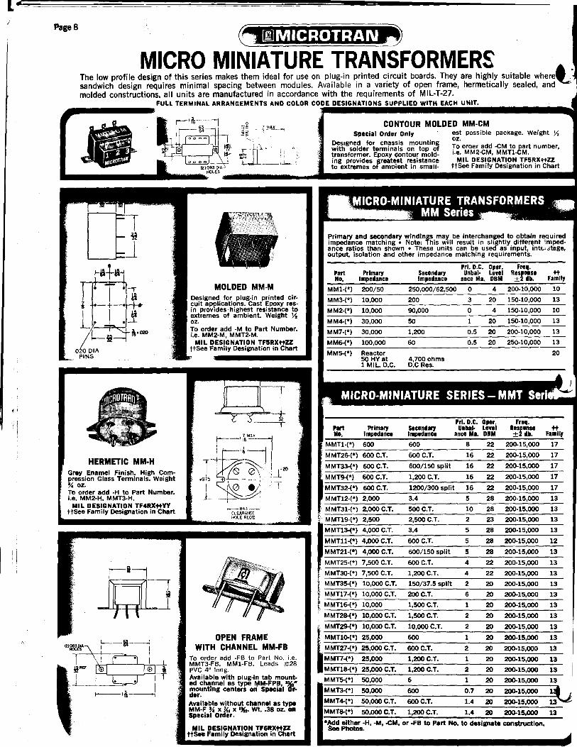
MICRO MINIATURE TRANSFORMERS The low profile design of this series makes them ideal for use on plug-in printed circuit boards. They are highly suitable wherel sandwich design requires minimal spacing between modules. Available in a variety of open frame, hermetically sealed, and molded constructions, all units are manufactured in accordance with the requirements of MIL-T-27.
FULL TERMINAL ARRANGEMENTS AND COLOR CODE DESIGNATIONS SU UNIT • .-----
~ .-1.
r.,ozo
HERMETIC MM·H Grey Enamel Finish. High Compression Glass Terminals. Weight % oz. To order add -H to Part Number. i.e. MM2-H. MMT3-H.
MIL DESIGNATION TF4RXttVY ttSee Family Designation in Chart
MOLDED MM-M Designed for plug-in printed cir. cuit appUcations. Cast Epoxy res· in provIdes' highest resistance to extremes of ambient. Weight y. oz. To order add -M to Part Number. i.e. MM2-M, MMT2-M.
MIL DESIGNATION TF5RXttZZ ttSee Family Designation in Chart
10--84.3 ___ CLEARAN:E HOLE AEQ'D
OPEN FRAME WITH CHANNEL MM·FB
To order add -FB to Part No. i.e. MMT3-FB, MM1-FB. Leads #28 PVC 4" long. Available with plug-in tab mounted channel as type t,1M·FPB, %" mounting centers on Special Cfrdar. Available without channel as type MM-F % x~. x',,". wt •• 38 oz. on Special Order.
MIL DESIGNATION TF6RXttZZ ttSee Family Designation in Chart
CONTOUR MOLDED MM-CM Special Order Only
DeSIgned for cnassis mounting with solder terminals on top of transformer. Epoxy contour molding proVidesJreatest resistance to extremes amDient in small-
est possible pacKage. Weight y. oz. To oroer add -CM to part number, i.e. MM2-CM, MMTl-CM.
MIL DESIGNATION TF5RXttZZ ttSee Family Designation in Chart
Primary and secondary windings may be interchanged to obtain required impedance matching. Note: This will result in slightly different imped· ance ratios than shown • These units can be used as input, intE.L:itage, output, isolation and other impedance matching requirements.
PrJ. D.C. Oper. Freq. Part Unbal· Level tt Primary Secondary Response No. Impedance Impedance ance Ma. DBM +2 db. Family
MM1-(*) 200/50 250,000/62,500 0 4 200-10,000 10
MM3-(*) 10,000 200 3 20 150-10,000 13
MM2-(*) 10,000 90,000 0 4 150-10,000 10
MM4-(*) 30,000 50 20 1SO-10,OOO 13
MM7-(*) 30,000 1,200 0.5 20 200-10,000 13
MM6-(*) 100,000 60 0.5 20 250-10,000 13
MM5-(*) Reactor 20 50 HY at 4,700 ohms 1 MIL. D.C. D.C Res.
MICRO-MINIATURE SERIES - MMT Serl
PIrt Primary Secondary PrJ. D.C. Oper. Unbal- Level
Freq. Response tt
No. Impedance Impedance ance MI. DBM +2 db. Family
MMTl·(*) 600 600
MMT26-(*) 600 C.T. 600 C.T.
MMT33-(*) 600C.T. 600/150 split
MMT9-(*) 600 C.T. 1,2ooC.T.
MMT32-(*) 600 C.T. 1200/300 split
MMTl2-(*) 2.000 3.4
MMT31-(*) 2,OooC.T. 500 C.T.
" - * , MMTl9 ( ) 2,500 2,500 C.T.
,
MMTl3-(*) 4,000 C.T.
MMTll-(*) 4,000 C.T.
MMT21-(*) 4,000 C.T.
MMT3D-(*) 7,500 C.T.
I MMT35-(*) 10,000 C.T.
i MMTl7-(*) 10,000 C.T.
f MMTl6-(*) 10,000
i MMT28-(*) 10,000 C.T.
~ MMT29-(*) 10,000 C.T.
MMTlD-(*) 25,000
MMT27-(*) 25,000 C.T.
MMT7-(*) 25,000
MMTl8-(*) 25,000 C.T.
MMT5-(*) 50,000
3.4
600 C.T.
600/150 split
600 C.T.
1,200 C.T.
150/37.5 split
2ooC.T.
1,500 C.T.
1,500 C.T.
10,oooC.T.
600
600 C.T.
l,200C.T.
l,200C.T.
6
8 22 200-15,000 17
16 22 200-15,000 17
16 22 200-15,000 17
16 22 200-15,000 17
16 22 200-15,000 17
5 28 200-15,000 13
10 28 200-15,000 13
2 23 200-15,000 13
5 28 200-15,000 13
5 28 200-15,000 12
5 28 200-15,000 13
4 22 200-15,000 13
4 22 200-15,000 13
2 20 200-15,000 13
6 20 200-15,000 13
1 20 200-15,000 13
2 20 200-15,000 13
2 20 200-15,000 13
1 20 200-15,000 13
2 20 200-15,000 13
1 20 200-15,000 13
2 20 200-15,000 13
1 20 200-15,000 13
600 0.7 20 200-15,000
6OOC.T. 1.4 20 200-15.000
MMT3-(*) SO,OOO
MMT4-(*) 50,OOOC.T. ~\.i MMT8-(*) SO,oooC.T. 1,200C.T. I .• 20 200-15,000
*~ either -H, -M, -CM, or -FB to Part No. to designate construction. _Photos.
13
....,.j

• Page 9
SUB MINIATURE TRANSFORMERS A variety of compact, low silhouette, constructions makes this series ideal for use in designs requiring maximum space utilization. Your mechanical and environmental considerations can be easily filled with the broad choice of open frame, hermetically sealed and molded constructions. All units in this series are manufactured in accordance with the requirements of MIL-T-27.
FULL TERMINAL ARRANGEMENTS AND COLOR CODE DESIGNATIONS SUPPLIED WITH EACH UNIT.
MIL CASE SM-AF Gray Enamel Finish. Weight Ilia oz. Supplied with compression sealed ceramic terminals in MILT-27B-AF modified case. To order add -AF to Part Number. i.e. SM2-AF, SMT3-AF. MIL DESIGNATION. TF4RXtfVY
ttSee Family Designation in Chart
Primary and secondary windings may be interchanged to obtain required impedance matching ° Note: This will result in slightly different impedance ratios than shown ° These units C~1n be used as input, interstage, output, isolation and other impedance matching requirements.
PrJ. D.C. Oper_ Freq. Part Primary SecOnd., Unbal- Leyel Respanse ~ Na. Impedance Impedance ance Ma_ DIM +2 db. Family
SM1-(*) 200/50 250,000/62,500 0 6 8O-1Q,ooo 10
SM3-(*) 10,000 200 3 21 150-10,000 13
SM2-(*) 10,000 90,000 0 8 100-10,000 10
SM4-(*) 30,000 50 1 21 150-10,000 13
SM6-(*) 100,000 60 0.5 21 150-10,000 13
SM5-(*) Reactor 50 HY at 1 MIL. D.C. 3,000 ohms. D.C. Res. 20 Special Order Only
~ MOLDED SM·M
Designed for chassis mounting with solder terminals on top of transformer. Epoxy contour molding provides greatest resistance to extremes of ambient in smallest possible package. Weight IX oz. Designed for plug-in printed crr
cuit applications. cast Epoxy Resin provides highest resistance to extremes of ambient. Weight 1y' oz. To order add -M to Part Number. i.e. SM5-M, SMT5-M.
MIL DESIGNATION TF5RX~ZZ ttSee Family Designation in Chart
HERMttlC SM·H Grey Enamel Finish. Weight 1 oz. High Compression Glass Termi· nals. To order add -H to Part Number. i.e. SM2-H, SMT3-H.
MIL DESIGNATION TF4RX~VY ttSee Family Designation in Chart
Primary and secondary windings may be interchanged to obtain required impedance matching ° Note: This will result in slightly different impedance ratios than shown ° These units can be used as input, interstage, output, isolation and other inwedance matching requirements.
Part Primary No. Impedance
SMTl-(*) 600
oSMT26-(*) 600 C.T.
oSMT9-(*) 600 C.T.
SMTl2-(*) 2,000
SMTl9-(*) 2,500
oSMT36-(*) 2,500 C.T.
SMTl3-(*) 4,000 C.T.
oSMTl7-(*) 10,000 C.T.
SMTl6-(*) 10,000
SMTlO-(*) 25,000
SMT7-(*) 25,000
oSMTl8-(*) 25,000 C.T.
SMT5-(*) 50,000
SMT3-(*). 50,000
oSMT4-(*) 50,000C.T.
Secandary Impedance
600
PrJ. D.C. Oper. Unb,,- Level
ance ML DBM
9 23
600 C.T. 18 23
1,200 C.T. 18 23
3.4 5 30
2,500 C.T. 5 26
2,500/625 split 10 26
3.4 5 30
200 C.T. 6 20
1,500 C.T. 1 23
600 2 20
1,200 C.T. 1.5 20
1,200 C.T. 3 20
6 1 20
600 1 20
600C.T. 2 20
Freq. Respanse ±2 db.
200-15,000
200-15,000
200-15,000
200-15,000
200-15,000
200-15,000
200-15,000
200-15,000
200-15,000
200-15,000
200-15,000
200-15,000
300-15,000
300-15,000
200-15,000
FamllJ ~
17
17
17
13
13
13
13
13
13
13
13
13
13
13
13
oSMT8-(*) 50,000 C.T. 1,200 C.T. 2 20 200-15,000 13
oAdd either -AF, -H, -M, -CM, or -FB to Part No. to designate construction. see photos.
-These items not available in -AF case.
To order add -CM to part number, i.e. SM5-CM, SMT5-CM.
MIL DESIGNATION TF5RXtfZZ ttSee Family Designation in Chart
OPEN FRAME WITH CHANNEL SM-FB
To order add -FB to Part Number. i.e. SMT3-FB, SMI-FB. Weight '¥4 oz. Leads #28 PVC 4" long. Available with plug-in tab mounted channel as type SM-FPB '~2 mtg. centers on Special Order,
Available without mounting channel as type SM-F ~6 x Yo x ~. Weight .67 oz. on Special Order.
MJL DESIGNATION TF6RX tfZZ ttSee Family Designation in Chait
I
:1

.... Page 10
MINIATURE AUDIO MINIATURE TRANSISTOR TRANSFORMERS l
This group o~ tran~forme~s is. often referred to as "the designers series." It offers an extensive range of open frame, hermetica Ily sealed, plug-In, printed CirCUit, contour molded and plug-in molded construction.
In this series, MICROTRAN offers the widest spectrum of electrical and mechanical specifications. ALL TRANSFORMERS LISTED ARE AVAILABLE IN THE CONSTRUCTIONS ILLUSTRATED. All units are manufactured in accordance with the requirements of MIL-T-27.
FULL TERMINAL ARRANGEMENTS AND COLOR CODE DE$iGNATIONS SUPPlIEO WITH EACH UNIT.
25 DB magnetic shield. 2 ance holes on '){. match aluminum cased mounting.
OCTAL PLUG-IN M-P Sealed Plastic Housing. Weight 2 oz. To order add .p to Part No., i.e. MT3-P, MI-P. Diameter 1%,". Height above mtg. surface 1'%,".
MIL DESIGNATION TF6RX tt zz ttSee Family Designation in Chart
(
SHIELDED M-S Special Order Only
Double High Nickel Alloy Magnetic Shielded Version of M and MT Series. 65 db Shielding For Minimum Hum' Pick-Up.
Diameter 1){,'. Height l'~l'. Mtg. Centers, 1j{,'. Wt. 3 oz. 6-32 x Ye'" studs. Leads #28 PVC 4" long.
MIL DESIGNATION TF6RX tt zz ttSee Family Designation in Chart To order add -5 to Part No. i.e. MI-S.
All items shown in charts below are available in any of the mechanical packages shown on pages 8 & 9 • These units can be used as input, interstage, output, isolation and other impedance matching applications. Primary and secondary windings may be interchanged to obtain required impedance matching. Note: This will result in slightly different impedance ratios than shown.
Pri. D.C. Oper-Unbal. ating Frequency
Primary Secondary ance Level Response tt Part No.' Impedance Impedance Ma. DBM ±2 db. Family
M3-(*) 7.5/30 50,000 0 5 20-20,000 10
• M12-(*) 50/250 C.T. 50/250/600 C.T. 0 8 20-20,000 16
• M1-(*) 50/250/600 C.T. 50,000 0 5 20-20,000 10 MI-S Same as MI above-with dual nickel alloy shield
• M2-(*) 50/250/600 C.T. 50,000 C.T. 0 5 20-20,000 10 Ml4-(*) 200 Y, Megohm 0 9 80-3,000 10 M15-(*) 10,000 1 Megohm 0 11 100-2,500 10
• M8-(*) 15,000 50/250/600 C.T. 0 8 20-20,000 16 • M9-(*) 15,000 50/250/600 C.T. 4 21 150-20,000 13
M4-(*) 15,000 60,000 0 6 20-15,000 10 M5-(*) 15,000 60,000 4 14 200-20,000 15 M6-(*) 15,000 95,000 C.T. 0 5 20-15,000 10 M7-(*) 15,000 95,000 C.T. 4 11 200-20,000 15
• M10-(*) 30,000 C.T. 50/250/600 C.T. 0 8 30-50,000 • M11-(*) 50,000 50/250/600 C.T. 0 5 20-20,000
M13-(*) Reactor 300 hy. 0 d.c. 50 hy. @3 mao 6000 [J D.C.R. M90 Magnetic Shield Mu-Metal slip on can for MA Series. 25 db shielding.
*Add either -AG -H, -CM, -P, -PC, -A, -S, or -FB to Part No. to designate construction. photos.
• These items not available in -PC construction.
These units can be used as input, interstage, output, isolation and other impedance matching applications· Primary and secondary windings may be interchanged to obtain required impedance matching. Note: This may result in slightly different impedance ratios than shown. '
Pri. D.C. Oper-Unbal· ating Frequency
Primary Secondary ance Level Response tt Part No.' Impedance Impedance Ma. DBM ±2 db. Family
• MT2-(*) 100 10 C.T./40 C.T. 100 27 200-20,000 17 MT30-(*) 250 C.T. 500 10 30 200-15,000 17 MT23-(*) 250 C.T. 1000 10 30 200-15,000 17 MTl4-(*) 400 10 50 25 200-20,000 17
• MTl5-(*) 500 C.T. 210 30 27 300-20,000 17 MTl-(*) 600 600 10 23 200-15,000 17
·~T35~~·~~6~0~O~~ ______ -760~0~C~.~T~.&~6~00~C.~T~·-,iO~~~5 __ ~4i,~~2~0~,O~0~0~~1~6 __ MT26-(*) 600 C.T. 600 C.T. 20 23 200-15,000 17 MT9-(') 600 C.T. 1,200 C.T. 4 23 200-15,000 17 MT33-(*) 600/150 Split 600/150 Split 20 23 200-20,000 17
• MT22-(*) 600/150 Split 1,200 C.T. 4 23 200-15,000 17 MT29-(*) 1600 C.T. 450 15 30 200-15,000 13 MTl2-(*) 2,000 3.4 10 32 200-15,000 13 MT24-(*) 2,500 600 C.T. 10 32 200-15,000 13
• MTl3-(*) 4,000 C.T. 3.4 3 32 200-15,060 13 MTl1-(*) 4,000 C.T. 600 C.T. 3 32 20~15,OOO 13 MT21-(*) 4,000 C.T. 600/150 Split 3 32 200-15,000 13 MT25-(*) 7,500 C.T. 600 C.T. 8 32 200-15,000 12
• MT34-(*) 10,000/2500 Split 2000/500 Split 4 20 200-20,000 13 • MTlO-(*) 25,000 600 3 22 200-.15,000 13 • MT7-(*) 25,000 1,200 C.T. 3 22 200-15,000 13 • MTl8-(*) 25,000 C.T. 1,200 C.T. 6 22 200-15,000 13
MT5-(*) 50,000 6 3 20 300-15,000 13 MT3-(*) 50,000 600 3 20 300-15,000 13 MTS-(') 50,000 C.T. 1,200 C.T. 3 20 300-15,000 13
• MT20-(*) 50,000 C.T. 1200/300 Split 3 20 300-15,000 13 MT6-(*) 100,000 1,200 C.T. 1.4 17 200-15,000 13
*Add either -AG -H, -M, -CM, -P, -PC, -A, or -FB to part No. to designate construction. See photos.
• These items not available in -PC construction. tFor telephone line coupling or hybrid telephone line

, "
... t I I'
~
MOLDED M·M Designed for plug-in printed circuit applications. Cast Epoxy resin provides highest resistance to extremes of ambient. Weight 1% oz. To order add -M to Part No. i.e. M2-M, MT3-M. MIL DESIGNATION TF5RX tt ZZ
ttSee Family Designation in Chart
Special Order Only
Designed for chassis mounting with solder terminals on top of transformer. Epoxy contour molding provides greatest resistance to extremes of ambient in smallest possi ble package. wt 1 y, oz.
To order add -CM to part number i.e. M2-CM, MT3-CM. '
MIL DESIGNATION TF5RX tt zz ttSee Family Designation in Chart
Weillht 1.13 oz. To order add -FB to Part No. i.e. MT3-FB, M1-FB From stock. Leads 4" long·#28 PVC
Special Order
Available with plug'in tab channel, 1~2 mounting centers as Type M-FPB.
Available without channel as type M-F %X1X'~6' Wt. 1 oz.
MIL DESIGNATION TF6RX tt zz ttSee Family Designation in Chart
r-I<D =~ __ --'~- l
OJ
MIL CASE M·AG Grey Enamel Finish. Weight 2% oz. Supplied with compression sealed ceramic terminals in MILT-27B AG case (modified). :,"0 order add -AG to Pa rt Number, I.e., M2-AG, MT3-AG. MIL DESIGNATION TF4RX tt yy
ttSee Family Designation in Chart
MT21-PC, MT33-PC, MT3 have 8-.025 x .015 pins on . centers.
HERMETIC M·H Grey Enamel Finish. Weight 1!4 oz. High Compression Glass Terminals. To order add -H to Part Number, i.e. M2-H, MT3-H, from stock .
. 120 holes instead of slots, avail· able Special Order Only.
MIL DESIGNATION TF4RX tt yy ttSee Family Designation in Chart
Page 11
OPEN FRAME PRINTED CIRCUIT
M·PC Weight 1.2 oz. To order add ·PC to part number, i.e. MT3-PC, M3-PC. MIL DESIGNATION TF6RX tt ZZ
ttSee Family Designation in Chart
r-li-i
I I ;lIlA. !
ALUMiNUM CASED M·A Supplied \'!lith 2-56 screws. Weight 1.25 oz. To o'rder add -A to Part Number, i.e. MT3-A, M1-A. MIL DESIGNATION TF3RX tt YY
ttSee Family Designation in Chart
1
Ii
,I I

(-
Page 12
DECI-MINIATURE-FOR PRINTED CIRCUITS-
LOW LEVEL INPUT TRANSFORMERS
These units can be used as input, interstage, output, isolation and other impedance requirements • Primary and secondary windings may be inter-changed to obtain required impedance matching. Note: This will result in slightly different impedance ratios than shown.
Part No.
DCM1-PC DCM2-PC DCM3-PC DCM4-PC DCM5-PC DCM6-PC DCM7-PC DCM8-PC DCM9-PC DCMlO-PC DCMll-PC DCM12-PC DCM13-PC DCM14-PC DCM18·PC DCM19-PC DCM20-PC DCM21-PC DCM22-PC
DCM51·PC Choke DCM52·PC Choke
Choke
Primary Impedance
25000 C.T. 15000 C.T. 15000 C.T. 10000 C.T. 10000 10000 C.T.
5000 C.T. 4000 C.T. 4000 C.T. 4000 2500 C.T. 2500 2500 C.T. 2500 C.T.
600 C.T. 600 600 C.T. 600 C.T. 250 C.T.
Pri. D.C. Secondary Unbalance Impedance Ma.
1200 C.T. 2 15000 C.T. 3
600 C.T. 3 5000 C.T. 4 2500/625 Split 2 1500 C.T. 4
80,000 C.T. 6 1200 C.T. 6
600 C.T. 6 600/150 Split 3
2500 C.T. 8 2500/625 Split 4
625 C.T. 8 200 C.T. 8
50,000 C.T. 16 8000/2000 Split 8 200 C.T. 16 600 C.T. 16 600 C.T. 25
10 hy @ 0 ma d.c. 5 hy lfi 3 ma d.c. 5 hy (U) 0 ma d.c. 2 hy @ 5 ma d.c. 2.5 hy @ 0 ma d.C. 1 hy @ 7 ma d.c.
Operating Level
DBM
18 19 19 20 20 20 15 20 20 20 20 20 20 20 20 20 20 20 20
300!l DCR 155 !l DCR
75!l DCR
OECI-MINIATURE OCM·SERIES New Industrial/Commercial grade miniature printed circuit transformers. Rigid terminals provide fixed Jl10unti ng centers usually found in expensive molded transformers. Weight .5 oz.
LOW LEVEL CHOPPER INPUT TRANSFORMERS -------..L Used in Servo, measuring, and coupling circuits as an Input Transformer for low level amplifiers. Efficiently transfers 30 to 500 C.P.S. transducer or thermocouple signals to instrument amplifiers at signal levels from .5 Mu V to .5V. Low hUm pick up assured by three Mu-Metal shields. High permeability core provides high efficiency and low distortion. Resin potted to minimize magnetostrictive microphonics. Electrostatic shield brought out to external ground connection to eliminate chassis currents .
. Request Engineering Application Bulletin F184 Turn Ratio Ind. of Imped. of
Part Full Pri. % Pri. Full Pri. FUll Pri. D.C. Resistance Number To Full Sec. To FUll Sec. @ .5V. 60,Hz @ .5V. 60 HzFull Pri. Sec. Fig.
M8025 1:7.7 1:15.4 17.5 HY. 6,600 365 4140 B M8026 1:3.2 1:6.4 60 HY. 22,500 455 3500 B M8052 1:4.53 1:9.06 90 HY. 34,000 760 5220 B M8053 * 1:0.5 1:1 140 HY. 53,000 920 653 B M8112 1:0.5 1:1 450 HY. 80,000 2300 1600 B M8525 1:7.7 1:15.4 17.5 HY. 6,600 365 4140 BB M8526 1:3.2 1:6.4 60 HY. 22,500 455 3500 BB M8552 1:4.53 1:9.06 90 HY. 34,000 760 5220 BB M8553 * 1:0.5 1:1 140 HY. 53,000 920 653 BB
·*Secondary is center tapped.
Fig. B: TRIPLE MU-METAL CASE, 6-32 x :Va" mounting studs on 1112" centers. Weight 5 oz. P/a"D x P~{H.
Fig. BB: HERMETICALLY SEALED to meet MIL-T-27. Triple mu metal case, high compression glass terminals, 6-32 x %" mounting studs on 1112" centers; 1" dia. cut out for terminals. Weight: 5 oz.
SHIELDED PLUG·IN SHIELDED CASED Mounting Centers 1M." 6·32 x Yo" stunds.
IN-LINE MICROPHONE Single Mu·Metal shield, electrostatic shield, 20" shielded cable is to be terminated with desired connector.
LOW LEVEL MICROPHONE INPUT Octal Type
M8030·1 have 8 pins M8023·3 have 9 pins. Matches many ampli· fiers.
Fi .. o
_ ' TRANSFORMERS_
These Broadcast fidelity input transformers are double mu-metal shielded.
Part Pri. Sec. Magn. Level Freq. Resp. Number Imp. Imp. Shldg DBM ± 2db. H 0 W Fig.
M8027 200 40,000 25 +5 50-20,000 2~ 13j,xYo 2 D M8030' 200/50 C.T. 50,000 65 +5 20-20,000 2Va IVa D. 6 C M803I ,600 C.T.II50 50,000 65 +5 30-20,000 2Va IVa D. 6 C M8032t 250 C.T. 50,000 65 +5 20-20,000 2Va IVa D. 6 C M8033t 50 C.T. 50,000 65 +5 20-20,000 2Va IVa D. 6 C ~ 50/250 C.T./ 50,000 65 +5 20-20,000 1'%, I){, D. 3 M-S
600 C.T. - I
*M8030 is designed as a replacement for Ampex No. 1733-1. tM8032'and M8033 mates with sockets on many RCA amplifiers.
..,
•
•
~.
~ :1
~
r .,
---~------- ----------------------
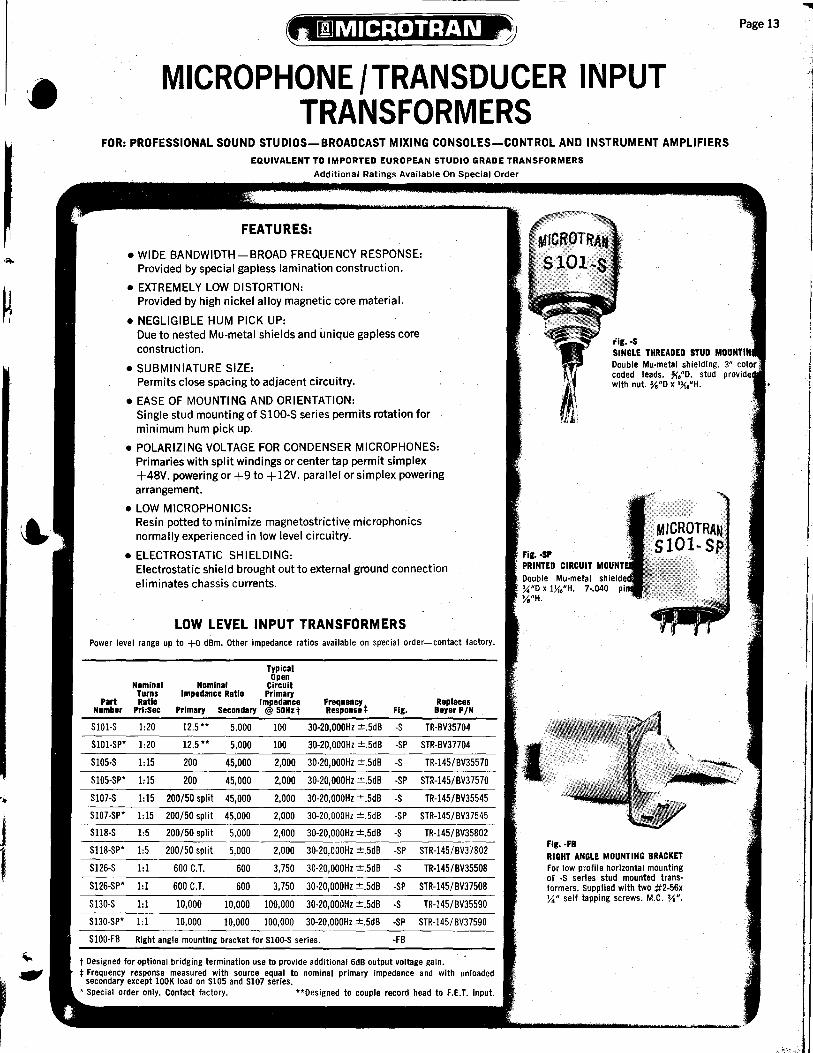
MICROPHONE/TRANSDUCER INPUT TRANSFORMERS
FOR: PROFESSIONAL SOUND STUDIOS-BROADCAST MIXING CONSOLES-CONTROL AND INSTRUMENT AMPLIFIERS
EQUIVALENT TO IMPORTED EUROPEAN STUDIO GRADE TRANSFORMERS
Additional Ratings Available On Special Order
FEATURES:
• WIDE BANDWIDTH-BROAD FREQUENCY RESPONSE: Provided by special gapless lamination construction.
• EXTREMELY LOW DISTORTION: Provided by high nickel alloy magnetic core material.
• NEGLIGIBLE HUM PICK UP: Due to nested Mu-metal shields and unique gapless core construction.
• SUBMINIATURE SIZE: Permits close spacing to adjacent circuitry.
• EASE OF MOUNTING AND ORIENTATION: Single stud mounting of S100-S series permits rotation for minimum hum pick up.
• POLARIZING VOLTAGE FOR CONDENSER MICROPHONES: Primaries with split windings or center tap permit simplex +48V. powering or +9 to + 12V. parallel or simplex powering arrangement.
• LOW MICROPHONICS: Resin potted to minimize magnetostrictive microphonics normally experienced in low level circuitry.
• ELECTROSTATIC SHIELDING: Electrostatic shield brought out to external ground connection eliminates chassis currents.
LOW LEVEL INPUT TRANSFORMERS Power level range up to +0 dBm. Other impedance ratios available on sp'ecial order-contact factory.
Typical
Nominal Nominal Open
Circuit Turns Impedance Ratio Primary
Part RatiO Impedance Frequency Replaces Number Pri:Sec Primary Secondary @ 50Nzt Respons.* Fig. Beyer PIN
S101-S 1:20 12.5 " 5,000 100 30-20,OOOHz ±.5dB -S TR-BV35704
SlOl-SP' 1:20 12_5 ,* 5,000 100 30-20,OOOHz ±.5dB -SP STR-BV37704
S105-S 1:15 200 45,000 2,000 30-20,OOOHz ±.5dB -S TR-145/BV35570
SI05-SP' 1:15 200 45,000 2,000 30-20,OOOHz ±.5dB -SP STR-145/BV37570
S107-S 1:15 200/50 split 45,000 2,000 30-20,OOOHz ±.5dB -S TR-145/BV35545
S107-SP* 1:15 200/50 split 45,000 2,000 30-20,OOOHz ±.5dB -SP STR-145/ BV3 7545
S118-S 1:5 200/50 split 5,000 2,000 30-20,OOOHz ±.5dB -S TR-145/BV35802
S118-SP' 1:5 200/50 split 5,000 2,000 30-20,OOOHz ±.5dB -sp STR-145/BV37802
S126-S 1:1 600 C.T. 600 3,750 30-20,OOOHz ±.5dB -S TR-145/BV35508
S126-SP' 1:1 600 C.T. 600 3,750 30-20,OOOHz ±.5dB -SP STR-145/BV37508
Sl30-S 1:1 10,000 10,000 100,000 30-20,OOOHz ±.5dB -S TR-145/BV35590
S130-SP' 1:1 10,000 10,000 100,000 30-20,OOOHz ±.5dB -SP STR-145/BV37590
SIOO-FB Right angle mounting bracket for S100-S series. -FB
t DeSigned for optional bridging termination use to provide additional 6dB output voltage gain. * Frequency response measured with source equal to nominal primary impedance and with unloaded secondary except lOOK load on S105 and S107 series_
, Special order only. Contact factory. *'Designed to couple record head to F.E.T. input.
Fig. -SP PRINTED CIRCUIT
%"D x 1X"H. Vel/H.
I-•. :-
Fig. ·FB
rig. ·S SINGLE THREADED STUD Double Mu·metal shielding. coded leads. Mo'D. stud with nut. Yo"D x l~o·H.
RIGHT ANGLE MOUNTING BRACKET For low profile horizontal mounting of ·S series stud mounted transformers. Supplfed with two #2-56x Yo" self tapping screws. M.C. Yo".
Page 13

Page 14
TELEPHONE COUPLING TRANSFORMERS
FOR INTERCONNECT OF VOICE/DATA MODEM TERMINALS TO TELEPHONE LINES
Designed to meet Telephone Company requirements for Data and Voice Access Arrangements Provides line isolation and matching - Prevents line imbalance Permits Optimum use of Voice-Grade Telephone Lines for Broadband Data Signals Wide Dynamic signal level capability - Low distortion • Frequency Response: • Distortion:
300-3500 Hz ± 0.5 dB 0.5% Max. • Level: • Impedance Matching:
-45 dBm to + 7 dBm ± 10% over entire frequency range • Longitudinal Balance: • Return Loss:
45 dB Min. 26 dB Min.
Part No. Application Primary Secondary
Impedance Impedance
11104 Coupling 600 600 T2104 Coupling 600 600 T2106 Coupling 600 C.T. 600 C.T. T2108 Coupling 600 900 T2110 Coupling* 900 900
T6112 Coupling* 600 900,600@ 60 mAD. C.
T2220 Hybridt 600 600/600 T3220 Hybridt 600 600/600 T2316 Bridging 4000 600
T4415 Holding Coil 2.0 hy @60 mA, 1.3 hy @ 100 mA D.C. 180n
T7410 Holding Coil 1.0 hy @O mA, 0.8 hy @ 25 mA D.C., 225n
T8410 Holding Coil 1.0 hy@O mA, 0.8 hy @ 40 mA D.C., 113n
t 2 requIred for Hybrid Operation, Trans-Hybrid loss 45 db typical. , Electrostatic Shield.
Available on special order with other ratings and construction.
DIMENSIONS
SIZE SERIES Fig. A B C D E F G
11000 1 y. ;)6 § .484 .235+ 1'32 .040' T2000 1 4%4 '%, § .420 .187+ lJ{6 .041 T3000 1 lu.. '%, § .781 .200 'u.. .041 T4000 1 1'%, rv" I'%'. 1.00 .312+ 1%, .041 nooo 2 l'u.. l'li. l'Y" 1.30 .400 1'%, .041
§ Do not have standoff. 'Round PinS .040" dia. t Pin location 2 and 5 not used on T1104, T2104, T2108, T2316, and T4415,
pin spacing is 2E.
Fig. No.
1 1 1 1 1
2
1 1 1
1
3
3
WT. OZ.
.4
.5 1.2 3.5 9.5
FIGURE 1 Plug-in printed circuit construction. Vacuum varnish impregnated.
Plug-in printed circuit construction with mounting channel. Vacuum varnish impregnated.
FIGURE 3 High-Q Toroid. Microcrystalline wax impregnated. Supplied with 4" #28 leads.
Size Wt. Series D H Oz. T7400 1 '%, Y. T8400 1Y. % 2
g3 rrr -'-'-Lt: -.-.- ~
t '4 l 02D E~E-l
REQUEST ENGINEERING APPLICATION BULLETIN F232
j !

Page 15
ULTRA MINIATURE TOROIDAL INDUCTORS Affords new application opportunities in high density packaging. Ultra miniaturized with low height design. Exceptionally high "Q" and wide frequency range. Available on special order with ± 1% inductance tolerance.
111450 MAX.
. 285 MAX
TOROIDAL INDUCTOR-QEL Series Frequency Range 1 KHZ to 300 KHZ - Accuracy ±2%
Typical Distributed
Part No. Inductance Typical Capacity
DCR p,p,F
QELl-M 1 Mhy. 2.1 25
QEL2-M 2 3.6 30
QEL5-M 5 7.3 35
QEL10-M 10 15.8 45
QELl5-M 15 20 45
QEL25-M 25 32 50
QEL50-M 50 69 50
QELlOO-M 185 70
"\.1 lUi! 22121$1\ VLCLSdl MILLIAMPS xv'MH
10 20 50 100 200 500
REPRESENTATIV~ CHA;;1e INITl------"'" ~ QEL
INDUCTANCe V5.A.C AND D.C
"'" \
<XITATION
20
\ 1\ \ \
D.C. EFFECT \ \ A.C: EFFECT
REPRESENTATIVE Q VS. V.,.......... 0-FREQUeNCY / y ~ CHARACTeRISTICS
// "'i~ 5
//-/" ~fo ~ 1
80
"Q"
60
40
o
102
100
98 ~ z
96 ~
94 ~ z
92 :: « 90~ 88 !Z 86~ .. 84
1 10 20 50 100 200 500 1000
0
"Q"
0
0
0
0 QEL -1
FREQUENCY IN KILOCYCLES
MILLIAMPS xv'MH 10 20 50 100 200 500
I
REPlleSENTATlVi CHANdE INIT/IL --........ "'" QEL
INDUCTANCE VS.A.C. AND D.C.
"'" \
EXITATION
\ \ \ \
D.C. EFFECT \ .\ AC. EFFECT
/ ---~ 1// '\ ~
~ / ~o 50 .~\ W"/ 25 15
REPReSENTATIVE Q VS. '----V FREQUENCY CHARACTEIIISTICS
J UL
1 00
98 ... u
96 ~ t;
94 5 z 92 :::;
« 90 ~ 88 ~
86 ~ 84
10 20 50 100 200 500 1000 • FREQUENCY IN KILOCYCLES
e300
e--. I I
MOLDED QEL·M QEM·M
Molded in high temperature epoxy resin • Leads .020" x 2" gold plated nickel alloy. Weight .02 oz.
To order, add -M to Part Number, i.e., QEL5-M, QEMIO-M.
TOROIDAL INDUCTOR-QEM Series Frequency Range 3 KHZ to 500 KHZ - Accuracy ±2%
Part No. Inductance Typical
DCR
Typical Distributed Capacity
p,p,F
QEM05-M 0.5 Mhy. 2.1 20
QEMI-M 3.8 30
QEM2-M 2 6.2 35
QEM5-M 5 15.9 45
QEM10-M 10 19 50
QEM15-M 15 42 55
QEM25-M 25 88 60
QEM50-M 50 193 70
MILLIAMPS XVMH 10 20 . 50 100 200 500
REPRESENTATIVE CHANGE INITIAL - -..... INDUCTANCE VS. A.C. AND D.C. ...... 1'. EXITATION '\ A.C. EFFECT
102
100
98
96
94
92
90
88
86
84
100
8
"Q"
0
60
0
20
o 1
100
8 0
"Q" , 6 0
0
0
0
1
'\ \ D.C. EFFECT \
QEM \ \ // ~ \
'l'/ ~ 2 T ~ 1
.5
ff. RePRESeNTATIVe Q VS. / FREQUENCY CHARACTERISTICY
...--1 10 20 50 100 200 500 1000
FREQUENCY IN KILOCYCLES
MILLIAMPS xv'MH 1 o 20 50 100 200 500
REPIIESENTATIVE CHANGE INITIAL ----...
INDUCTANCE V5.A.c. AND D.C '\ A.C. EFFECT EXITATION
'\ \ D.C. EFFECT \
QEM \ \ J---.., \
£ t---...' 1 .IlL b'i~1O
I#'/ 251
/. V f'so ~ ~ENTATIVE Q vs. t---
V FREQUENCY CHARACTERISTICS
102
100
98 ....
96~ .... 94 ~
o 92 "
90~ Z
:~ 84 ..
10 20 50 100 200 500 1000 QEM
•••••• IiIIIiIIiIIIiIIiIIIiI_. FREQUENCY IN KILOCYCLES ?SIiIIIiI _______ ,
'.1 i
.J
1:. I
ii' , I:, J
t. I
I, '
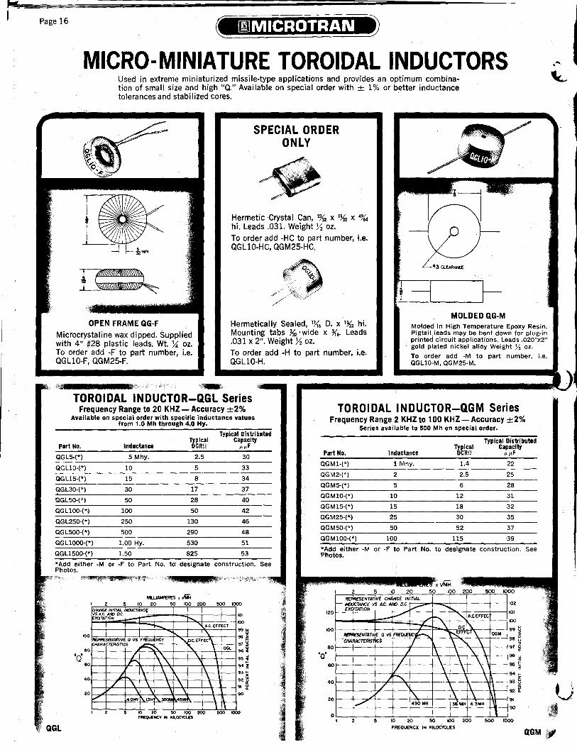
Page 16
MICRO-MINIATURE TOROIDAL INDUCTORS Used in extreme miniaturized missile-type applications and provides an optimum combination of small size and high "Q." Available on special order with ± 1% or better inductance tolerances and stabilized cores.
SPECIAL ORDER ONLY
Hermetic 'Crystal Can, % x % x 4%4 hi. Leads .031. Weight X oz. To order add -HC to part number, i.e. QGLlO-HC, QGM25-HC.
~ ,/ <"4 .. / / . /
CLEARAN:E
MOLDED QG-M OPEN FRAME QG-F
Microcrystaline wax dipped. Supplied with 4" #28 plastic leads. Wt. ~ oz. To order add -F to part number, i.e. QGLlO-F, QGM25-F.
Hermetically Sealed, 1}{6 D. x 1~2 hi. Mounting tabs ~2 'wide x ~6' Leads .031 x 2". Weight X oz. To order add -H to part number, i.e'. QGLlO-H.
Molded in High Temperature Epoxy Resin. Pigtail)eads may be bent down for plug-in printed circuit applications. Leads .020"x2" gold plated nickel alloy Weight Y:. oz.
,",jP t _;
TOROIDAL INDUCTOR-QGL Series Frequency Range to 20 KHZ- Accuracy ±2%
Available on special order with specific inductance values from 1.0 Mh through 4.0 Hy.
Typical Distributed Typical Capacity
Part No. Inductance DCRIl JLJLF
QGL5·(*) 5 Mhy. 2.5 30
QGLlO·(·*) 10 5 33
QGLl5-(*) 15 8 34
QGL30·(*) 30 17 37
QGL50-(*) 50 28 40
QGLlOO·(*~ 100 50 42
QGL250-(*) 250 130 46
QGL500·(*) 500 290 48
QGLlOOO-(*) 1.00 Hy. 530 51
QGLl500-(*) 1.50 825 53
* Add either -M or ·F to Pa rt No. to' designate construction. See Photos.
'00
80
'Q' 60
40
20
.~ J II 2 :'S:::
MlLLJAMPERES • IiiH 10 20 50 100 200 soo 1000
'" 100
99i 980"
97 ~ 96.
95~ 94~
93 ~
92 ~ ~
91 ~
0i4NGE. INITIAL lfOJCTANC{ VSA.c. AJIC) ac. naTATION --r t--....
;-.., A.C. EFFECT
\. ~PRESENTJlnVE Q VS FREQU NCr " /lc. EFFEC1\
HARACT£RJSTlCS ~ I'.. \ OGL
/ .\. \. \ r. \\. \
1\ \ 1\ \ ~ \ \ I\, \ \
/ \. \ \ \ \ OK>
V 4.0HY 1\'3H p\."""" 4,MI \ \ 1\
10 20 ~ 100 200 500 lOCK)
FREQuENCY .. KL.OC'tCLES
To order add -M to part number, i.e. QGLlO-M, QGM25-M.
TOROIDAL INDUCTOR-QGM Series Frequency Range 2 KHZ to 100KHZ - Accuracy ±2%
Series available to 500 Mh on special order.
tYPical Distributed
Part No. Inductance Typical DCRIl
Capacity JLJLF
QGM1-(*) 1 Mhy. 1.4 22
QGM2·(*) 2 2.5 25
QGM5-(*) 5 6 28
QGM10-(*) 10 12 31
QGM15-(*) 15 18 32
QGM25-(*) 25 30 35
QGM50-(*) 50 52 37
QGM100-(*) 100 115 39
*Add either -M or -F to Part No. to designate construction. Photos.
..---.... xvMii I 2 5 10 20 50 100 200 500
120
100
REPRFSeNTATIVe r;IM:NGe INiTIAL , f- ~~-jfo~ VS AC. AND DC . ........- ......
--+- Lt:::--... "'- A.c.EFFEC
'T- _\ -.Ocr-..: REPRESE:N1JlTlV< Q VS t-.....EFFECT
\ QGM --
80
'0' 60
CHARACTf:Rt5 ",5 'L 1\ " \ j 1\ \ '\\
/ \ \ \ \ V "l \ \
40 .I~ \ \ ./ " 1\
20 I'\. ; \ \ ~ 430MH 36 .... 43MH ,
, I
02
01
100
99
98
97
96
95
94
93
9Z
91
90
o I 10 20 50 100 zoo 500 1000
See
,'"
u QGL FREQUENCY. I'" KLOC'ICLES
G'GM,

SUB-MINIATURE TOROIDAL INDUCTOR The excellent "Q" characteristics of this series l\Iake it ideal for the size and weight requirements of portable airborne equipment. This series is available on special order with ± 1 % or better inductance tolerances and stabilized cores.
MOLDED QI·M Molded in high temperature Epoxy. Silver plated terminals. To order add -M to part number, i.e. QILlO-M, QIL25-M. Weight 1112 oz. On special order threaded insert is available in place of clearance hole.
HERMETIC QI-H Hermetically sealed in metal case. Teflon terminals assure permanent seal at temperature extremes. To order add -H to part number, i.e. QILlO-H, QIL25-H. Weight 1¥2 oz. On special order available with inserts in place of studs.
OPEN FRAM E QI-F M icrocrysta II i ne wax dipped. Supplied with 4" #28 plastic leads. Weight ~ oz. To order add -F to part number, i.e. QIL250-F.
TOROIDAL INDUCTOR - QIL Series Frequency Range to 20 KHZ - Accuracy ± 2%
Available on special order with specific inductance values through 7.0 Hy.
Typical Typical Distributed
Capacity Part No. Inductance DCRO /L/L F
QIL3-(*) 3 Mhy. .73 36
QIL5·(*) 5 1.1 38
QIL10-(*) 10 2.1 40
QIL15-(*) 15 3.3 42
QIL25·(*) 25 5.3 45
QIL50·(*) 50 11 47
QIL100-(*) 100 22 49
QIL150-(*) 150 34 50
QIL250-(*) 250 55 53
QIL500-(*) 500 95 55
QILlOOO·(*) 1.00 Hy. 210 57
QIL1500-(*) 1.50 335 59
QIL2500-(*) 2.50 550 61
*Add either -M, -H, or -F to Part No. to designate construction. See Photos.
MIU.IAMPERES x v1iIH I 2 . 10 20 .0 M)O 200
1~~~TIYf' HANGC INiT/Al INOUCTANC£ vs A C ANDI 0 C
-I-
'10
N .'50 QI40
('XC/TATION -I-' AC [",Ur''\.
r--. \ I
o.c.uftcr""- \ \. \
REPRESENTATIVE a \IS F'RfOOENCY ~ '-....... CHARACTERISTICS
100
00
r--r--
40
o .1
!---
~ .\. OIL
/' \.\. .;--. \. \.
\. \. \. ........ 'MY, 500". !10M" ~ ... \.. \.. \..
I 2 5 10 20 50 100 FAEOU£NCY IN KiLOCYCLES
QIL
Page 17
i I

I, ,
Page 18
MINIATURE TOROIDAL INDUCTOR Their characteristiC6 permit high "Q", power level, and stability in a unit with reasonable size and weight. Both series available on special order with ± 1 % or better inductance tolerances and stabilized cores.
~"d1$\ ~111C!ii.h, /~' y
•
MOLDED QK-M Molded in high temperature epoxy resin. Silver plated terminals. To order add -M to part number, i.e. QKllO-M, QKM25-M. Weight 3341 oz. On special order threaded insert is available in place of clearance hole.
OPEN FRAME QK-F Microcrystalline wax dipped. Supplied with 4" #28 plastic leads. To order add -F to part number, i.e. QKLlO-F, QKM25-F. We 2 oz.
TOROIDAL INDUCTOR - QKL Series Frequency Range to 10KHZ - Accuracy ±2%
Available on special order with specific inductance values to 17.5 Hy.
Typical Typical Distributed Part No. Inductance DCRQ Capacity /k/kF
QKL5-(*) 5 Mhy. .62 60
QKL10-(*) 10 1.1 66
QKL15-(*) 15 1.7 68 Part No.
QKL25-(*) 25 2.8 72 QKM2-(*)
QKL50-(*) 50 6 76 QKM5-(*)
QKL100-(*) 100 11 81 QKMlO-(*)
QKL150-(*) 150 17 83 QKM25-(*)
QKL250-(*) 250 28 87 QKM50-(*)
QKL500·(*) 500 63 91 QKM100-(*)
QKL1000-(*) 1.00 Hy. 110 96 QKM250-(*)
QKL1500-(*) 1.50 175 98 QKM500-(*)
QKL2500-(*) 2.50 275 103 QKM1000-(*)
HERMETIC QK-H Hermetically sealed in metal case. Teflon terminals assure permanent seal at temperature extremes. To order add -H topart number, i.e. QKLlO-H, QKM25-H. Weight 3341 oz. On Special Order available with inserts in place of studs.
Typical Distributed Typical Capacity
Inductance DCRQ /k/kF
2 Mhy. .45 52
5 1.1 58
10 2.5 62
25 6.5 70
50 11 74
100 25 79
250 65 87
500 115 92
1.00 Hy. 250 97
QKL5000-(*) . 5.00 645 106 *Add either -M, -H, or -F to Part No. to designate construction. See Photos.
QKL10,OOO-(*) 10.00 1175 112
*Add either -M, -H, or -F to Part No. to designate construction. See Photos.
QKL
.., - ~. "'" IMO
~ ~ - 'J 1\ A C [ffECT
IIIORrSfMlTNf 0W(jf ,,.TiIl ~ oc".,.:a\. ==~AFIK}OC
fQO
110
010
'(j"" "0 "" 10
--.. 10
40
20 01....--
"1 Qv'~ /
1/ t--.
/
:;7 .. ".;"'\: "\.
"\. OKL
!"':;;;;: r"'-
\. I"\. \ "\.
~ "..,\ -\ I>MH """"
" \1
~
'0' 101 .. 91 .. " ..
It ,02050100 '''UNC'I' IN ICI.OClCL.£S
;rrrrt:r l;S T:U r Dr '

".
• ___ L
Page 19
HIGH-Q TOROIDAL INDUCTORS Permits construction with high power ratings and sharp frequency characteristics. This series is avai lable on special order with ± 1 % or better inductance tolerances and stabi lized cores. Available on special order with specific inductance values to 75 Hy.
~------------- -----~------~-----...
H (§)
L'---_(§) __
MOLDED -M Molded in high temperature epoxy resin. Silver plated terminals. To order add -M to part number, i.e., QPL25-M. QTL25-M. On special order threaded insert is available in place of clearance hole.
MODEL D H C WGT.
QPL·M 2" 1" # 10 6 oz. a QTL·M 2Ys" 1 %" # 10 14 oz.
~"-.-.--~.....,.--
TOROIDAL INDUCTOR - QPL
HERMETlC-H Hermetically sealed in metal case. Teflon terminals assure permanent seal at temperature extremes.
Series Dimensions
A B C
lX6
')j,
r 4) b-32 STUDS
r
Wt. D E Oz.
1~. 1'~. 9y'
2)j. 2'1. 16
TOROIDAL
OPEN-FRAME-F Microcrystalline wax dipped, 4" #24 Leads. To order add -F to part number, i.e., QPL25-F, QTL25-F.
MODEL D H C WGT.
Ys" lJi'2 min. 5 oz. 1" % min. 9 oz.
INDUCTOR - QTL Series Series Frequency Range to 15 KHZ - Accuracy ±2%
Frequency Range to 10 KHZ - Accuracy ±2% Typical Distributed
Typical Distributed T&piCal Capacity
Part No. Inductance CRn p.p.F T&piCal Capacity
25 Mhy. Part No. Inductance CRn p.p.F QTL25-(*) .85 127
QPL25-(*) 2S Mhy. 1.5 100 QTLSO-(*) SO 1.5 136
QPLSO·(*) SO 2.S lOS QTLlOO·(*) 100 2.8 144
QPLlOO·(*) 100 6 110 QTL1S0·(*) ISO 3.9 149
QPL250·(*) 250 IS 115 QTL2SO.(*) 250 7 156
QPL500·(*) SOO 25 120 QTLSOO-(*) SOO 15 164
QPLlOOO·(*) 1.00 Hy 60 12S QTLlOOO-(*) 1.00 Hy. 27 173
QPL1S00·(*) 1.S0 90 130 QTLlSOO-(*) 1.50 40 177 QPL2S00·(*) 2.S0 150 133 QTL2S00-(*) 2.50 70 184
QPLSOOO·(*) 5.00 350 138 QTL5000-(*) 5.00 140 192
QPL7S00-(*) 7.S0 525 140 QTL10,000·(*) 10.00 270 200 . QPLlO,OOO-(*) 10.00 600 142 QTLI5.oo0·(*) lS.00 430 205
QPLlS,OOO·(*) lS.00 900 146 QTL2S.000-(*) 2S.00 8S0 212
QPL25,000·(*) 2S.oo lS00 150 QTLSO,OOO-(*) SO.OO 1500 221
*Add either -M,,·H. or·F to Part No. to designate construction See Photos.
MIlUAMP£ArS x {iiH I 2 10 20 '0 200 000 1000 0000
I AC EFFECT
260
2_
220
200
110 ..., Iid'MO
120
~. 100
~CH/Wj/£IMTIAL --t"-... "' o NJUCTANCl V$ A.C AND DC (xaTAnON h " " I \ ~T f----V"'\
I I \ \ QTL RD'fIESENTA1M' 0 1/, F __ NCr I \ \ CHARAC'TERlSncs I
~ \ \ ,- .0
.0
40
20
QTL
L. \ 1\ \
'/ 60HY \ IOHY \ 2MY \~ --- r-- \ \ \ o 10 20 100 ZOO!lOO ZtC 51( JOt( OOKIOOk
FR£QI..€NC'I' IN aa.u

Page 20
D.C. to D.C. CONVERTER TRANSFORMEpc APPLICATIONS:
• Portable Radiation Monitors. Infra-Red Detectors. Op-Amp Power Supplies
• D.C. Isolation. Geodetic-Oceanographic-Medical Equipment
• Mobile Equipment. High Intensity Flashers. D.C. Supply for Modular Equipment .~ A BROAD SELECTION OF RATINGS AND DESIGNS TO FILL YOUR CIRCUIT REQUIREMENTS
i~ FIG. B
FIG. E FIG. F
FIG.C FIG. G
FIG.H "'~*I$jH;~,ffYL;L;P:(j%&IJXiJh.tWIf$L4;Ut£ iLK : ~ ...... j d .. ! hjJ·~_;
TYPICAL D.C.-D.C. CONVERTER TRANSFORMER CIRCUITS
R C2
Schematic 3
Schematic 1 001 ",d 001"'"
Schematic 4
CRj:1N459 C5 SELECTED SO
THAT Vz ~255±!OV.
Schematic 6
Schematic 7
. +oc VOLTS
I!~ -DC. VOLTS
CR5.6-IN484A + EIN -Schematic 10
Schematic 9
CR2,CR3.CR4 IN3255
Schematic 5
Schematic 8
ALL TRANSFORMERS ARE SUPPLIED WITH ENGINEERING BULLETIN, LISTING COMPONENT VALUES

• Page 21
I~.C. to D.C. CONVERTER TRANSFORMERS
I I ..
1-------........ -- -- Switch Approx.
SELECT THE UNIT THAT
MEETS YOUR POWER
AND SIZE REQUIREMENTS
Catalog Number
'1' . W D.C: OUTPUT-- f l' , Total i D.C. C.T. Frequenc Sche.! VA... Inpu BRIDGE FULL WAVE Hz matici
Typical ,i ~DIMENSIONS
Transis- Mtg. Centers Type of Construction
Fig Weight Output Volts Volts I MA Volts MA approx.. NO., tor D W H MD MW No Oz.
NEW M8149 1000* 2511A 400 , 3 i 2N670 lIlt.
25 mw to
M80S0 1
3 :2N670 I'}),
i ~---~--~--~-----+----1---1---~----~---
M80S1 125 mw! 3 1000* 25 I1A - - 400 3 j2N670 1
~·--·L-----~-4~----~-----r---4r---~-----;----1
M8073: 25 mw j 4 425-500 50l1A - - 50-3Kt 5 /2N1305 Ye
1000* 2511A 25 mwl3 400 1~, lYe
lYe 1Ys
i Ye
Plug-In - Printed
Circuit IF/1.25
_ Laminated ' D: 1.25 -Open Frame i
; 1 I Laminated .I E I
- -MIL Case AGI I : I
_ Laminated I 8 I -Open Frame
!
2.4
.1 190 mw
HIGH VOLTAGE LOW POWER MINIATURE DESIGN
M8074 , 50 mW)3 535* 90l1A I - - 400 6 12N414 I'}), lYe i Laminated I - -Open Frame l D i 1.25·~~
, ~---~---4I--~----~----~I---4---4~---4--'-1
M8072 190 mw I 2.7 480* 40011A: - - 800 2 i2N1307 1% '~, lYe Laminated ! i
- -Open Frame I 0 ! 1.25 l
NEW 3 VA DiSPLAYS NIXIE-PANAPLEX SP-300/SP·l00
5 VA HIGH VOLTAGE LOW PROFILE ENCAPSULATED
I
%/% I i ~----I-----4---4------~-----4----+----4------~---
! I M8t20 190 mw :28 480* 400l1A - - 3.5K 9 j2N4355 1'){,
M8t21 3 5 190 15 20K 11 ;2N6121 Ji. D X 1~2 H - :\:
lYe Laminated
- -Open Frame
Pot CoreOpen Frame
H
M811S 5 -+-250 Toroid- i
.3
13.8 ,-500~r 10 250 20 6K 8, 2N3054 1 Ys D x % H - .140 CI. Hole Encapsulated C I 1.1
L-~----~~l----~---+--4---~--~_~I~--+----------------r-------rTi---¥ I: I iCil -+-250 Toroid-
,28 :,-500~r 10 250 20 6K 7 2N3054 I 1Ys D x % H - .140 CI. Hole Encapsulated ! 1.1
j 1 M8117
L
5
NEW I M8122 5 5 +15 or 30 175 15 350 20K 7 12N3055/ 1114 D X 3/4 H - .140 CI. Hole
Molded Toroid Plug-In
I M8132 , 30 ±. 15 or
13.8 30. 1000 15 2000 20K 7 12N3055 lYs D x % H - .140 CI. Hole rToroidEncapsulated ,C
i 1.1 '~ 30 VA
HIGH SWITCHING FREQUENCY LOW PROFILE ENCAPSULATED
t----, i I ~----~--~-----+------~--~!~--~-----4I----~----+------------------------~--------~!--r----,~
Ft. 15 or 1000 15! 2000 20K 7 l2N3055 lYs. D x %. H - .140 CI. Hole Toroid- i C 11 M8133 30 28 30. Encapsulated .
HIGH4eoV
trAGE ,M8036 40 113 6 '±225 or I 90 1225 155 800 1 '2N442 Ii, 2~, 2){, j; 3Ys 11){1! 1~, Laminated- A lYs
_H_ER_M_E_T_IC ___ +I ___ ~ ___ ~_' ~jr-4_50_._-+ _______________ ~ __ ;-_~ ______ 4-_~r-_4-_4-__ ~_M_I_L_c_a_se_FA_~ _____ .i M8113 I 50 13.8 f2~~or
i I I
50 VA M8114 50 28 ~ 14 or 1 28.
LOW PROFILE ENCAPSULATED M81t6 i 50
1750 14 i 3500
i 1750 14 13500
I 700 35 ! 1400
2.5K 7 2N3055 2Ya D x 1Ys H - .170 CI. Hole
2.5K 7 2N3055 2);'; D x lYs H - .170 CI. Hole
2.5K 7 2N3055 2Ys D x 1Ys H - .170 CI. Hole
Toroid-Encapsulated C 6 ; ToroidEncapsulated C
ToroidEncapsulated C
6
6
MEDIUM POWER ~
~--~--+-----;-----~--~--+-----~-4----~------------------~--------+-+----
. M8118 50 28 b. 35 or 70. 700 35 1400 2.5K 7 2N3055 2Ys D x 1Ys H - .170 CI. Hole Toroid
Encapsul~ted C 6
125 VA HIGH VOLTAGE HIGH POWER HERMETIC
M803S 25 36 ±250 or . 500.
128 ±250 or 500.
250 250
:j: Supplied with 4-40 nylon mtg. screw and nut'" center hole.
420 800 1 i2N442 2% 2% 3'~, ;
1 12N174
A Full wave and C.T. loads may be simultaneously drawn, but for continu9us duty, total V.A. output should not be exceeded . • For positive and negative voltage supply as utilized in op-amp and similar circuitry, use secondary circuit #10.
1'/. Laminated/. MIL Case GA
1 % LaminatedMIL Case GA
A '2Ys Ibs.
* Output when used with schematic indicated. ** Based on approximately 1 volt drop per rectifier. t Frequency depends on load and bias conditions.

(
I
~ ,I
)!
Page 22
INTERPRETATION OF TYPE DESIGNATION PER MIL-T-27 ~ ........................................ ~ .• ~
TF 4 R X 01 FA 001 Type of Component: ~
TF - Transformer
Grade: 4 Hermetic Metal Cased 5 Sealed Encapsulated 6 Open Frame Impregnated
Class: (Ambient + Rise) ___ ---I (Ambient Must be Specified) Q 85·C. Operating R 105·C. Operating
T I IdonU'""" Serial number assigned only to MS units
Case and Mounting Dimensions See MIL-T-27 for Case Size and Mtg.
~----- Family (Circuit Application) 01 Pwr. Transf.-Unrect. Loads 02 Pwr. Transf.-Rect. Loads 03 Pwr. Transf.-Rect. and Unrect. Loads 04 Power Inductor See MIL-T-27 for Listing
S 130·C. Operating V 155·C. Operating '"-------- Life Expectancy T 170·C. Operating U 170·C. + (As Specified)
EQUIVALENCY DECIMAL TEMPERATURE
1/64-.0156 ·F ·C 1/32-.0313 662 350 1/16-.0625 392 200 3/32-.0938 374 190 1/8 -.1250 356 180 5/32-.1563 338 170 3/16-.1875 320 160 7/32-.2188 311 155 1/4 -.2500 302 150 9/32-.2813 284 140 5/16-.3125 266 130 ,
11/32 - .3438 257 125 3/8 -.3750 248 120
13/32 - .4063 221 105 7/16- .4375 212 100
15/32 - .4688 194 90 1/2 -.5000 185 85
17/32-.5313 '176 80 9/16-.5625 r 158 70
19/32 - .5938 ,'149 65 5/8 -.6250 140 60
21/32 - .6563 131 55 11/16 - .6875 (. 122 50 23/32 - .7188 104 40 ) 3/4 -.7500 95 35
25/32 - .7813 86 30 13/16-.8125 77 25 27/32 - .8438 68 20 7/8 -.8750 50 10
29/32 - .9063 32 0 15/16 - .9375 +14 -10
3lf32-.9688I -4 -20 1 -1.000;f .-40 -40
-67 -55 . -".
. . -85 -65
X 10,000 Hrs. Min. Y 2,500 Hrs. Min.
STANDARD MIL-T-27 CASES
Case -Case Dimensions- -Mounting Dimensions-symbol L W H ML MW F
POWER AF % % 1Y. *'~. 4-40X%
dbm Power AG 1 1 1% *1Y. 6-32X%
-30 1.0",w. AH 1~. 1~. 1% S:l% 6-32X%
-20 10.0 AJ 1% 1% 2% 1~. 1~. 6-32x%
-10 100 EA 1'~. 1'~. 2% 1% 1% 6-32X%
-6 250 EB 1'~. 1'~. 2U. 1% 1% 6-32x%
-5 320 FA 2~. 2X. 3y' lolX. 1U. 6-32X% -4 400 FB 2~. 2X. 2Y, l'X. 1U. 6-32X% -3 500 GA 2% 2% 3'~. 2Ya 1% 6-32X% -2 630 GB 2% 2% 2'~. 2Ya 1% 6-32X% - 1 794 HA 3X. 2% 4% 2'%. 1~. 8-32x%.
0 1.0mw 3~. 15~
1 1.3 HB 3X. 2% 2'%4 B-32x%
2 1.6 JA 3X. 3X. 4% 2% 2Ya B-32x%
3 2.0 JB 3X. 3X. 3% 2% 2Ya B-32x%
4 2.5 KA 3'~. 3% 5)4 3 2U. 10-32XY,
5 3.2 KB 3'~. 3% 4~. 3 2U. 10-32xY,
6 4.0 LA 4~. 3'X. SU. 3~. 2'X. 10-32XY, 10 10.0 LB 4~. 3'X. 4Y, 3~. 2%. 10-32XY, 15 31.6 MA 4'X. 4 6 3'X. 3 %-20x% 20 100 MB 4'X. 4 4'~. 3'X. 3 %-20xY. 25 320
NA Sx. 4~. 6'~. 4X. 3~. %-20x% 30 1.0 watt 35 3.2
NB sx. 4~. SY, 4X. 3~. Ya-20xY.
40 10 OA SY, 4Y, 6% 3% 3 %-20xY.
45 32 *Not in conformance with MIL-T-27 S: Two studs in a diagonal.
50 100 YY-AII metal cases not included above or with non-standard mounting 60 1000 centers. ZZ-Open type & encapsulated units.
70 10KW 1. Tolerances on dimensions Land Ware +0 to -X. for cases AF, AG, 80 100KW AH and AJ; +0 to -Ya for all other cases.
9011000KW 2. Tolerances on dimension Hare +0 to -Ya for cases AF, AG, AH,
100 10 Meg. and AJ; +0 to -?i'. for all other cases.
3. Tolerances on dimensions ML and MW are ±u. for cases AJ to JB inclusive; ±X, for cases KA to LB, inclusive; and ±j(" for cases MA to OA, inclusive. When mounting studs or holes for inserts are used, they
P shall be symmetrically located.
dbm - 10Iog-1- 4. Screw-stud lengths are from mounting surface and have a length mw. tolerance of ±){. on studs Y," long or less & ±y. on studs over y," L.
~
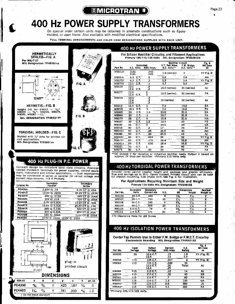
Page 23
400 Hz POWER SUPPLY TRANSFORMERS On special order certain units may be obtained in alternate constructions such as Epoxy molded, or open frame. Also available with modified electrical specifications.
FULL TERMINAL ARRANGEMENTS AND COLOR CODE DESIGNATIONS SUPPLIED WITH EACH UNIT.
HERMETICALLY SEALED-FIG. A
Per MIL·T·27 MIL Designation: TF4RX01xx
HERMETIC-FIG. B Height (H) for MB063 - 'X.". MB069 - l~.", MB05B, MB075, MBOB1, MBOB2 -l){.".
NIIL DESIGNATION TF4RX01YY
TOROIDAL MOLDED-FIG. C Molded with y," pins for printed circuit applications. MIL Designation: TF5SX01xx
plug-in
printed circuit
DIMENSIONS SERIES A B C 0 E
4,%4 23;3'2 t .420 .187 1){6
Ih4 2~2 t .781 .200 6){4 t Do not have sta ndoff
WT.OZ.
.5
1.2
For Silicon Rectifier Circuitry. and Filament Applications Primary 105/115/125 Volts MIL Designation: TF4RX01XX
Rectifier Circuit Fig. A Secondary C. T. Full Wave F.W. Bridge Mil Case
Part No. A.C. Volts RMS Amps. D.C. Volts" D.C. Volts" XX MB063t 2.B5 .045 1.5·(series) 3 YY Fig. B 2.B5 .045 MB064t 6.3 C.T. .6 1.9 3.B AH MB075t 6.3 C.T. .3 1.9 3.B YY Fig. B MB076t 12.6 C.T. .3 4.7 9.4 AH MB039 12.6 .S 10.5 (series) 21 (series) AJ 12.6 C.T. .S MB077 12.6 2 10.5 (series). 21 (series) FA 12.6 C.T. 2 MS03S 12.6 .3
12.6 .3 16 (series) 32 (series) AJ 12.6 .3
MBOlB lB.5 C.T. 1 7.4 l4.B EA MB019 1B.5 C.T. 3 7.4 14.S FA MS065 26 C.T. 1.5 10.S 21.6 EA MS066 26 .C.T. 3 10.7 21.5 FA MS079 26 C.T. 4 10.S 21.6 ·HA MS067 30 C.T. 1.5 12.5 25 FB MB020 35 C.T. 3 14.5 29 GA MS06S 40 C.T. .2 17 34 AJ MS04lt 50 C.T. .25 21.5 43 AH MSOSO 50 C.T. .20 21.5 43 AJ MS069t 60 C.T. .003 26 52 YY Fig. B MB070t 65 C.T. .170 2S.4 56.8 AH MBOSlt 65 C.T. .030 2B.4 56.S YY Fig. B MS02l 70 C.T. 1 30 60 FA MS07l SO C.T. .90 35 70 FA
""DC Output V for resistive or inductive rectifier loads. Output V based on approx. IV drop per rectifier. tPrimary 115 Volts only
i cores permit smaller height and package and greater efficiency. Size and savings up to 30 %. Epoxy molded. Printed circuit pins can be bent for chassis mounting. Low phase shift. See Fig. C for illustration.
For Applications Requiring Minimum Size and Weight Primary 115 Volts MIL Designation: TF5SX01ZZ
Secondary Secondary Dimensions Nominal Part No. Volts Current rna V.A. 00 Height Weight OZ MSl06 2S C.T. 320 9 1~2 lYe 2 MB107 2B C.T. 710 20 IX IX 4 MSlOS 56 C.T. 160 9 1~2 lYe 2 MBl09 56C.T. 356 20 IX IX 4 MB110 115 C.T. 7S 9 1~2 lYe 2 MS111 115 C.T. 170 20 IX lYe 4
.170 Clearance Hole for #8 Screw
400 Hz ISOLATION POWER TRANSFO~MERS
Center Tap Permits Use In Either F.W. Bridge or F.W.C.T. Circuitry Electrostatic Shielding MIL Designation: TF4RX01XX
Fig. A Input Output Current V.A. Mil Case
Part No. Voltage Voltage RMS Amps Rating II
MBOB2 26 12.6C.T. .15 1.9 YY (Fig. B) 12.6 .15 1.9
MS05S 115 115C.T. .017 2 YY (Fig. B) MBOS3 115 115 C.T. .030 10
12.6 C.T. .25 Total AJ 12.6 .25
MSOS4 115 115 C.T. .12 14 AJ MS059 115 115 C.T. .35 40 EB MBOS5 115 115 C.T. .7 SO FA MS060 115 115 C.T. 1.3 150 GA MS06l" 115 115 C.T. 2.6 300 JA MS062" 115 115 C.T. 4.4 500 KA
'Primary 105/115/125 volts.
~
....

III
,.
Page 24 c_ml~1t3;t'}i;l!'~1 ,
60 Hz POWER SUPPLY TRANSFORMERS Designed for solid state and low voltage applications. All units shown are hermetically sealed and manufactured in accordance with the requirements of MIL-T-27.
FULL TERMltlAL ARRANGEMENTS AND COLOR CODE DESIGNATIDNS SUPPLIED WITH EACH UNIT. ........ .~ .. ~ HERMETICALLY
SEALED
Per MIL·T·27 MIL Designation: TF4RXOlxx
See Page 25for MILCase Dimensions. Also available in open frame con· .struction, see page 18.
METHOD OF APPROXIMATING SECONDARY AC
CURRENT REQUIREMENTS Since transformers may be used in many possible configurations, the current ratings shown above are ACRMS secondary winding currents. When selecting the "Secondary Amp" rating, the conversion chart shown below may be helpful. For exact values of secondary current requirements; use curves prepared by O.H. SHADE "Proc of IRE 7/43 Analysis of. Rectifier Operation."
Rectifier Approx.
Secondary Type Filter Type RMS Current
Full Wave Choke Input .7 times Center-Tap DC current
Full Wave Capacitor Input 1.2 times Center-Tap DC current
Full Wave Choke Input Equal to Bridge DC curr-ent
Full Wave Capacitor Input 1.8 times Bridge DC current
For Silicon Rectifier Circuitry, and Filament Applications Primary 105/115/125 Volts MIL Designation: TF4RX01xx
Rectifier Current Fig. A Secondary C.T. Full Wave F. W. Bridge MIL Case
Part No. A.C. Volts RMS Amperes D.C. Volts·· D.C. Volts·· xx
MB042 6.3 C.T. .6 1.9 3.B AJ MB043 6.3C.T. 2.0 1.9 3.B FB MBOB6 6.3 C.T. 6.0 1.9 3.B GA MBOS7 12.6 C.T. 3.0 4.7 9.4 GA MB044 12.6 2.0 10.5(series) 21(series) JB
12.6 C.T. 2.0 MB022 lS.5 C.T. 3.0 7.4 14.S JB MSOBS 26 C.T. 2.5 10.B 21.6 HA MB152 2S C.T. .15 11.7 23.4 AJ MS045 28 C.T. .6 11.7 23.4 FA MB055 30 C.T. 2.5 12.5 25 JA MB023 35 C.T. 3.0 14.5 29 KA MSOS9 40 C.T. .1 17 34 ·AJ MB090 40 C.T. .3 17 34 EA MB091 40 C.T. .75 17 34 GB MB046 49 C.T. 2.5 21 42 LA MB024 70 C.T. 1.0 30 60 JA MB056 BO C.T. .6 35 70 HA
**D.C. Output for resistive or inductive loads. Output volts based on approx. 1 v. drop per rectifier.
ON/POWER TRANSFORMERS . Center Tap Permits Use In Either F.W. Bridge Or F.W.C.T. Circuitry
Electrostatic Shielding MIL Designation TF4X01xx
Fig. A Input OUtput Current V.A. MIL Case
Part No. Voltage Voltage RMS Amps Rating xx M8094 115 115 C.T. .0085 1 AH M80~5 115 115 C.T. .030 3.5 EA
12.6 C.T. .25 3.15 12.6 .25 3.15
MB151 115 115 C.T. .13 15 .FA MB096" 115 115 C.T. .35 40 GA MB07B* 115 115 C.T. .9 100 KA
"Primary 105/115/125 Vqlts.
Fig. K
FILTER INDUCTORS 1500 Test Volt-May be connected in series or parallel for inductive requirements. Part numbers listed on left are
hermetically sealed per MIL Designation TF4RX04XX. Part numbers listed on right are open frame construction. HERMETIC Series Connected Parallel Connected Fig. A OPEN FRAME DIMENSIONS
Part Inductance D.C. D.C.R. Inductance D.C. D.C.R. MIL Case Mtg. Part No. Henrys Amps Ohms Henrys Amps Ohms xx L W H Centers Fig. No.
M809B 3.5 .050 200 .B75 .10 50 AH 2Ye lYe 1:1\'. 1% FB MS19B
M8099 1.0 .15 65 .25 .30 16 AJ 2% '1% Ill, 2 FB MB199
MB100 .5 .3 30 .125 .6 7.5 EB 2':1\', 1% 1% 2% FB MB200
I
MB101 .32 .6 16 .OB 1.2 4 FB 3% 1% 1'~. 2':1\'. FB ::0 MB102 .2 1.0 4 .05 2.0 1 JA 3% 2% 3%, 2'~.X2Ya K
MB103 .07 2.5 .B4 .0175 5.0 .21 JA 3% 2% 3'%. 3Yax2y. K MB203
MB104 .022 4.0 .4 .0055 B.O .1 JA 3% 2% 3%, 2%X2y. K MB204
MB105 .022 5.0 .2 .0055 10.0 .05 KA 4y. 3Ya 4~, 3%x2y. K MB205

I
Figure
FB
Fi,Utu
K
Page 25
60 Hz CONTROL AND POWER SUPPLY TRANSFORMERS For Relays, Silicon Rectifiers Circuitry, and Filament Application Primary 105/115/125 Volts
Part No.
MB242
MB243
M8286
M8287
MB247t
MB244
MB222
M8288
M8245
MB255
M8223
M8289
M8290
MB291
M8246
M8224
MB256
Secondary A.C. Volts RMS Amperes
6.3 C.T. .6
6.3 C.T. 2.0
6.3 C.T.
12.6 C.T.
12. 12.
12.6 C.T. 12.6
1B.5 C.T.
26 C.T.
28 C.T.
30 C.T.
35 C.T.
40 C.T.
40 C.T.
40 C.T.
49 C.T.
70 C.T.
BO C.T.
6.0
3.0
4.0 4.0
2.0 2.0
3.0
2.5
.6
2.5
3.0
.1
. 3
.75
2.5
1.0
.6
Rectifier Circuit C.T. Full Wave F.W. Bridge
D.C. Volts** D.C. Volts"" L
1.9 3.B 2%
1.9 3.B 3Xi
1.9 3.B
4.7 9.4
9.9(series) 19.B(series) 4);8
10.5 (series) (21 (series) 3%
7.4 14.8 3%
10.B 21.6 3
11.7 23.4 3Xi
12.5 25
14.5 29 4Y.
17 34 2%
17 34 2'K • 17 34
21 42
30 60 3%
35 70 3
Dimensions W H
Mounting Centers Figure
1% 1Y. 2 FB
1% 1'~. 2'K. FB
2% 2Xi 3Xi FB
2);8 2Xi 3);8 FB
3);8 3% K
2'K. x 2Y. K
2'K. x 2);8 K
2% 2% 2Y. x 2% K
2);8 1'~. 2'K. FB
2% 3'%, 3);8 x 2Xi K
3 3% 3~. x 2% K
1% 1Y. 2 FB
1% 1% 2% FB
2);8 2Xi 3);8 FB
3Xi 4~, 3% x 2Y. K
2% 3'%, 3);8 x 2Xi K
2% 2% 2Y. x 2% K
tSecondary may be connected in series to provide 24V @ 4.0 amperes or parallel for 12V @ 8.0 amperes. *"D.C. Output for resistive or inductive loads. Output volts based on approx. 1 v. drop per rectifier.
50·60 Hz STEP DOWN AUTO TRANSFORMERS 240/220V. to 120/110V. 50/60 cycle. Equipped with secondary standard receptacle. 6' U.L. approved line cord. Baked Enamel Finish.
DIMENSIONS Part No. Application L W H Mtg. Ctrs. Weight
M1552 80 Watt capacity 3);8 3.5Ibs.
M1556 100 Watt capacity 3);8 2% 3Y. 1% x 2Xi 4lbs.
M1553 150 Watt capacity 3Xi 2% 3Y. 2Xi x 2% 5lbs.
M1555 250 Watt capacity 3% 3Xi 2'J1.x 2Y. 6lbs.
M1559 350 Watt capacity 3% 3% 4% 2~, x3 7lbs.
M155B 500 Watt capacity 4% 3r" x 3 121bs.
M1551 750 Watt capacity 5% 3Xi x 3Y. 161bs.
M 1557 1000 Watt capacity 7 4 Y. 5% 5Xi x 3Y. 251bs.
M1554 1500 Watt capacity B 4Y. 5% 6Xi x 3Y. 291bs.
"M1550 2000 Watt capacity BY. 4% 6 371bs. iJERTICAL END BELL
"Secondary supplied with 1 foot #14-2 wire stripped cable.
PI ... re K
60 Hz ISOLATION and POWER TRANSFORMERS Center Tap Permits Use in Either F.W. Bridge Or F.W.C.T. Circuitry Electrostatic Shielding
Part No.
M8294
MB295
MB251
M8296"
M8278*
Input Voltage
115
115
115
115
115
Output Voltage
115 C.T.
115 C.T. 12.6 C.T. 12.6
115 C.T.
115 C.T.
115 C.T.
*Primary 105/115/125 Volts.
Current V.A. RMS Amps Rating
.0085 1
.030 3.5
.25 3.15
.25 3.15
.13 15
.35 40
.9 100
Dimensions L W H
2);8 1);8 1~,
2'~. lYe 1%
3Xi 1% 1'~.
4 2Xi 2".
Mounting Centers Figure
1% FB
2% FB
2'K. FB
3". FB
3Xi 3'~ 3Ye x 2% K
1 ·1 'I Ii

, ~ I' j
I:'
I • i
Page 26
PLUG-IN PRINTED CIRCUIT POWER TRANSFORMERS ~ 115V And 115/230V 50/60 Hz Primary
• compact Design For Miniaturized Solid State Circuitry • Precision Spaced Molded-In Terminals
For applications such as power supplies, instruments, and control equipment. Constructed per MIL-T-27 Grade 6 Class R. Class S avai lable on special order. Dual secondaries may be parallel connected to obtain twice the current, or series connected to give twice the voltage of one winding. Lugs on PC2000 series provide for 115/230V. primary voltage options without changes in PC board.
115/230V. I--_---:c---=--:~~:-:-se-co-nd__.arr_y-~___,_-__:__c,_____ 115V. Primary Primary Parallel Connected I Series Connected
Part No. /Fig. Part No. -'Fig. AC Volts 1 RMS Amps. L AC Volts JRMS Amps
SERIES PC6500{PC1500 1 V2 Watt Series PC6506 C PC2506 A 6.3 .250 (S",le ST'd"Y) PC6512 C PC2512 A 12.6 .120 25.2 CT .060 PC6524 C PC2524 A 40.0 .040 80.0CT .020 PC6528 C PC2528 A 58.0 .026 116.0 CT .013
SERIES PC6600/PC2500 4% Watt Series PC6608 D PC2608 B 6.3 .700 12.6 CT .350 PC6616 D PC2616 B 2B.0 .156 56.0 CT .07B PC6624 D PC2624 B 40.0 .110 BO.OCT .055 PC6628 D PC2628 B 5B.0 .066 116.0 CT .033 PC6632 D PC2632 B 115.0V @ 020A and 12.6V @ .150A SERIES PC6700/PC2700 7% Watt Series
PC6708 D PC2708 B 6.3 1.200 12.6 CT .600 PC6712 D PC2712 B 12.6 .600 25.2 CT '.300 PC6715 D PC2715 B 20.0 .370 40.0CT .185 PC6716 D PC2716 8 2B.0 .270 56.0 CT .135 PC6724 D PC2724 8 40.0 .180 BO.OCT .090 PC6728 D PC2728 B 58.0 .130 116.0 CT .065 PC6732 D PC2732 8 115.0V @ .025A and 12.6V @ .250A
115 Volts
Primary
2 PRJ.
PC6000 Series PC2000 Series
Series PC65001 PCT6500 (FIG. C) may also be used for point to point wiring by cementing the transformer with the terminals opposite mounting surface.
Series PC6600/PCT6600 and PC6700/PCT6700 (FIG. B) may also be supplied for point to point wiring on special order with terminals opposite mounting surface. To order, add -FBR to PIN, ie PC6604-FBR and add $10.00 lot set-up charge.
.. r--A~ rwtCBO 1 c B
11t UJ. -H-o;----t
PC2500 Series
I
FIG.B J PC6500 Series - 6 pi
PCT6500 Series - 8 Pins U
I f r r FIG. C r:=A-----,
rrQpC6600 & PC6700 Series - 6 Pins ' c L PCT6~OO & PCT6700 Series - 8 I - J,.
....J1-.04~
·PC6900·FB mtg. bracket avail. on spec. ordor; four %," holes on 1% X 2" ctrs. tDo not have standoff.
p 7

/ Page 27
(JPLUG-IN PRINTED CIRCUIT POWER TRANSFORMERS For Logic and OP AMP Power Supplies
~~"IIII""~~RCUITPOWER'RANSFORMERSFOR+5V1,A·N·D·±·1·5-V·,-DC"PO·W"ER"SU·P·P·L·'E·S" For construction of low cost, miniaturized, regulated and unregulated DC power supplies for latest solid-state digital and linear circuitry. Permits packaging flexibility unobtainable with prepackaged power supplies. Low-profile, miniaturized construction permits close stacking of PC boards. Precision spaced molded-in terminals.
Jffif::: SECONDARY DC OUTPUT
Parallel Connected Series Connected Part r-------- C.T.F.W. Current No. ACVo!ts RMSAmps ACVoits RMSAmps DC Volts mA DC
PC6211 12.0 0.07 24.0 C.T. 0.035 ±15 22 PC6511 12.0 0.13 24.0 C.T. 0.065 ±15 40 PC6611 12.0 0.40 24.0 CT. 0.200 ±15 120
SCHEMATIC #3 UNREGULATED PCL6611* 12.0 0.40 24.0 C.T. 0.200 ±15 120 PC6711 12.0 0.76 24.0 C.T. 0.380 ±15 220
I~\I ~l~~. PC6911 12.0 1.90 24.0 C.T. 0.950 ±15 550
] PC6214 16.0 0.05 32.0 C.T. 0.025 ±20" 15
~r~~ PC6514 16.0 0.10 32.0 C.T. 0.050 ±20" 30
IrD~ PC6614 16.0 0.30 32.0 C.T. 0.150 ±20" 90 PCL6614*' 16.0 0.30 32.0 C.T. 0.150 ±20" 90 PC6714 16.0 0.56 32.0 C.T. 0.280 ±20" 165 PC6914 16.0 1.411 32.0 C.T. 0.700 +20" 410
Sche-matic
No.
3 3 3 3 3 3 4 4 4 4 4 4
SCHE~ATIC #4 REGULATED •• ±20 D.C. outpuT 70llS for input to ±15V. output IC Voltage Regulator, see schematic 4.
Fig. No.
E C D F D E E C D F D E
TRANSFORMERS FOR +5V AND ±15V DC TRIPLE OUTPUT UNREGULATED AND REGULATED POWER SUPPLIES * All primaries 115V 50/60 Hz except PCL6630 and PCL6631 which have 115/230V 50/60 Hz primaries E¥=:5V.
JE!tt;:: SCHEMATIC #5 UNREGULATED
8f~ JD2Et~
Secondary #1 Secondary #2 DC Output #1 DC Output #2 Sche-
Part AC RMS AC RMS C.T.F.W. Cur. C.T. F.W. Cur. matic Fig. No. Volts Amps Volts Amps DC Volts mADC DC Volts mADC No. No.
PCT6230 9.0 C.T. 0.048 24.0 C.T. 0.020 +5 40 ±15 12 5 E PCT6530 9.0C.T. 0.072 24.0 C.T. 0.032 +5 60 ±15 20 5 C PCT6630 9.0C.T. 0.240 24.0 C.T. 0.080 +5 200 ±15 50 5 D PCL6630* 9.0 C.T. 0.240 24.0 C.T. 0.080 +5 200 ±15 50 5 F PCT6730 9.0 C.T. 0.480 24.0 C.T. 0.160 +5 400 ±15 100 5 D PCT6930 9.0C.T. 1.200 24.0 C.T. 0.440 +5 1000 ±15 275 5 E PCT6531 15.5 C.T. 0.048 32.0 C.T. 0.020 +8.5" 40 ±20** 12 6 C PCT6631 15.5 C.T. 0.140 32.0 C.T. 0.058 +8.5" 115 ±20·* 35 6 D PCL6631* 15.5 C.T. 0.140 32.0 C.T. 0.058 +8.5-' 115 ±20** 35 6 F PCT6731 15.5 C.T. 0.300 32.0 C.T. 0.100 +8.5" 250 ±20·· 60 6 D PCT6931 15.5,LT. Q.690 31.0 C.T. 0298 +85" 575 -+-20'- 175 6 E
SCHEMATIC #6 REGULATED ** +8.5 and ±~o D.C. output volts are for inputs to +5V. and ±15V. IC Voltage Regulators, see schematic 6.
ALL TRANSFORMERS ARE SUPPLIED WITH ENGINEERING BULLETIN LISTING SUGGESTED COMPONENTS
FIG. E
Bulletin provides typical schematics and suggested components for low-cost, miniaturized, unregulated and regulated power supplies. Regulated units have short circuit, thermal overload and overvoltage protection, and have the following typical specifications: Input 105-l25V; Output Voltage ±.IV; Load and Line Regulation .1% each; Ripple lmV RMS.
PC/PCT6200 & PCT6900 Series-8 Pins PC6900 Series-6 Pins jErE,
r'-"l ITA Q.lLW
-JLo.;---r .JEIEIEL .020
PCL6600 Series·
[g I:;:4 JL.040D1A
FIG. F
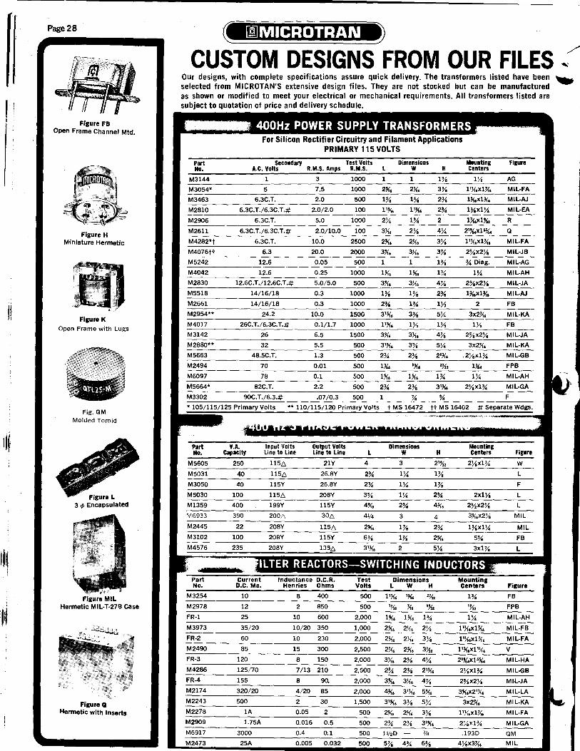
-
I ! i
"~ I I
Page 28
Figure FB Open Frame Channel Mtd.
Figure H Miniature Hermetic
Figure K Open Frame with Lugs
Fig. QM
Molded Toroid
Hermetic MIL-T-276 Case
Figure Q Hermetic with Inserts
CUSTOM DESIGNS FROM OUR FILES ~ Our designs, with complete specifications assure quick delivery. The transformers listed have been .. selected from MICROTAN'S extensive design files. They are not stocked but can be manufactured as shown or mOdified to meet your electrical or mechanical requirements. All transformers listed are subject to quotation of price and delivery schedule.
Part No.
M3144
M3054*
M3463
M2810
M2906
M2611
M4282*t
M4076tt
M5242
M4042
M2830
M5518
M2661
M2954**
M4017
M3142
M2880**
M5663
M2494
M6097
M5664*
M3302
For Silicon Rectifier Circuitry and Filament Applications PRIMARY 115 VOLTS
Secondary A.C. Volts
1
5
6.3C.T.
6.3C.T./6.3C.T.#
6.3C.T.
6.3C.T./6.3C.T.#
6.3C.T.
6.3
12.6
12.6
12.6C.T./12.6C.T.#
14/16/18
14/16/18
24.2
26C.T./6.3C.T.#
26
32
48.5C.T.
70
78
82C.T.
90C.T./6.3.#
R.M.S. Amps
3
7.5
2.0
2.0/2.0
5.0
2.0/10.0
10.0
20.0
0.05
0.25
5.0/5.0
0.3
0.3
10.0
0.1/1.7
6.5
5.5
1.3
0.01
0.1
2.2
.07/0.3
Test Volts R.M.S.
1000
1000
500
100
1000
100
2500
2000
500
1000
500
1000
1000
1500
1000.
1500
500
500
500
500
500
500
Dimensions L W
1 1
1% 1%
1'~. 1'~.
2X 1%
1 1
1% 1%
3'~. 3%
lYe
2% 2%
1~
2% 2%
1
H
1%
3Y. 2%
2%
2
4X
3Y.
3%
1%
1%
4%
2%
5X
lYe 4%
5X
2'~.
2~2
1%
Mounting Centers
lYe
2%x2Ye
% Diag.
IX 2%x2Y.
2
3x2~.
3x2~.
.2Yex1%
1~
* 105/115/125 Primary Volts ** 110/115/120 Primary Volts t MS 16472 tt MS 16402
Part No.
M5605
M5031
M3050
M5030
M1359
M6933
M2445
M3102
Part No.
M3254
M2978
FR-1
M3973
FR-2
M2490
FR-3
M4286
FR-4
M2174
M2243
M2278
M2909
M6917
M2473
V.A. Capacity
250
40
40
100
400
390
22
100
Input Volts Line to Line
1156
1156
115Y
1156
199Y
2006
208Y
208Y
Output Volts Line to Line
21Y
26.8Y
26.8Y
208Y
115Y
306
1156
235 208Y
Current D.C. Ma.
10
12
25
35/20
60
85
120
125/70
155
320/20
500
1A
1.75A
3000
25A
8 400
2 850
10 600
10/20 350
10 230
15 300
8 150
7/13 210
8 90.
4/20 85
2 30
0.05 2
0.016 0.5
0.4 0.1
0.005 0.032
L
4
2%
2%
500
2,000
1,000
2,000
2,500
2,000
2,500
2,000
2,000
1,500
500
500
500
500
Dimensions W
3
IX IX 2%
3
1%
3){. 2% 4X
H
1%
2%
4
2%
2% 2% 2'~.
3'~. 3% 5);.;
11120 7/8
Mauntlng Centers
2x1Y.
3~.x2Ye
1%x1X
lX
2Y.x1%
2y.x2Y.
.1930
Figure
AG
MIL-FA
MIL-AJ
MIL-EA
R
Q
MiL-FA
MIL-JB
MIL-AG
MIL-AH
MIL-JA
MIL-AJ
FB
MiL-KA
FB
MIL-JA
MIL-KA
MIL-GB
FPB
Figure
w L
F
L
L
MIL
MIL
Figur.
FB
FPB
MIL-AH
MIL-FB
MIL-FA
V
MIL-HA
MIL-GB
MIL-JA
MIL-LA
MIL-KA
MIL-FA
MIL-GA
QM
MIL
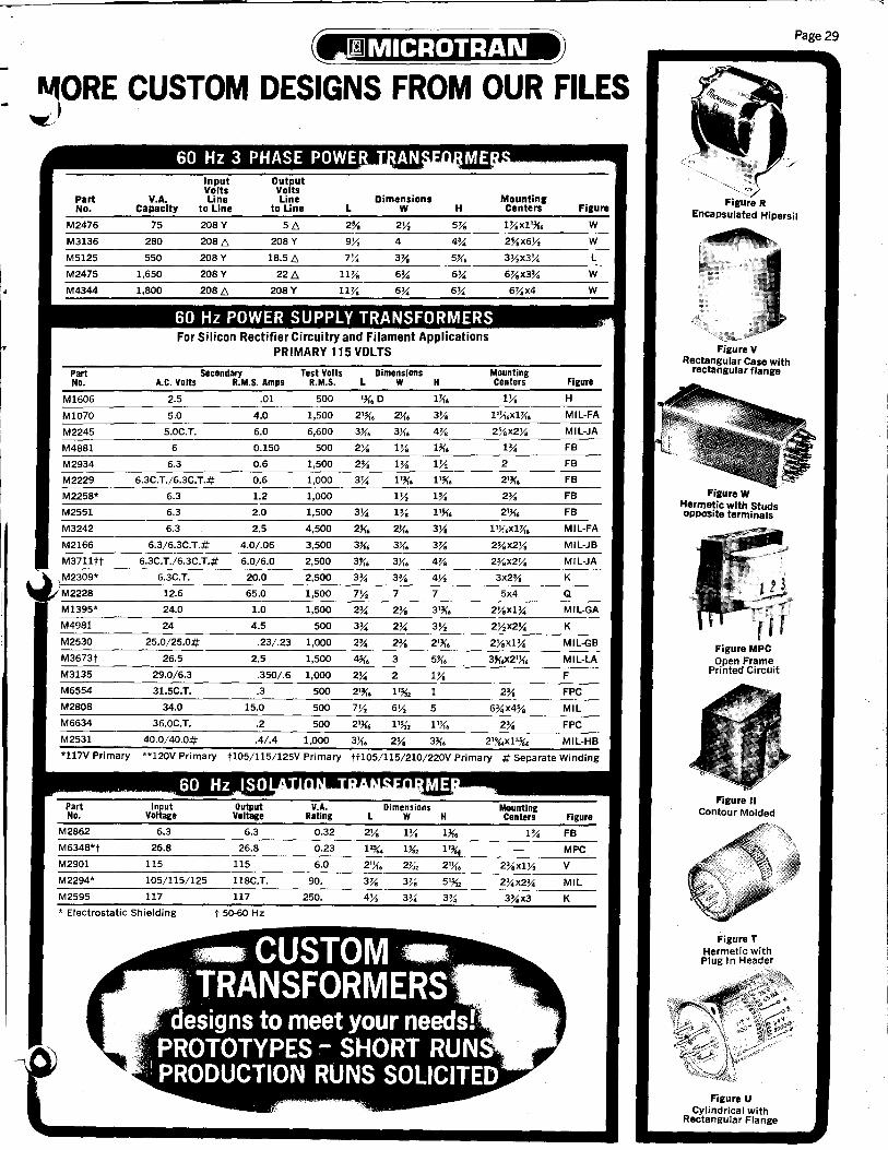
~ORE CUSTOM DESIGNS FROM OUR FILES ~)
Part No.
M2476
M3136
M5125
M2475
M4344
Part No.
M1606
M1070
M2245
M4BB1
M2934
M2229
M225B*
M2551
M3242
M2166
M3711 tt
,M2309*
M222B
M1395*
M49B1
M2530
M3673t
M3135
M6554
M2BOB
M6634
M2531
*117Y Primary
V.A. Capacity
75
2BO
550
1,650
l,BOO
Input Volts Line
to Line
20BY
20BL',
20BY
20BY
20BL',
5L',
20BY
1B.5 L',
22L',
20BY
Dimensions L W H
2% 2J/, 5Y.
9J/, 4 4%
7% 3Y. 5U.
11Y. 6% 6%
11Y. 6% 6%
Mounting Centers
60 Hz POWER SUPPLY TRANSFORMERS For Silicon Rectifier Circuitry and Filament Applications
PRIMARY 115 VOLTS
Secondary Test Volts Dimensions A.C. Volts R.M.S. Amps R.M.S. L W H
2.5 .01 500 '~.D
5.0 4.0 1,500 2'~.
5.0C.T. 6.0 6,600
6 0.150 500 2Ya 1Ya
6.3 0.6 1,500 2% 1%
6.3C.T./6.3C.T.# 0.6 1,000 1'~.
6.3 1.2 1,000 1%
6.3 2.0 1,500 3% 1%
6.3 2.5 4,500
6.3/6.3C.T.# 4.0/.06 3,500
6.3C. T./6.3C. T.# 6.0/6.0 2,500 3)1. 4Va
6.3C.T. 20.0 2,500 3% 3%
12.6 65.0 1,500 7 7
24.0 1.0 1,500 2% 2%
24 4.5 500
25.0/25.0# .23/.23 1,000 2% 2% 2'~.
26.5 2.5 1,500 3 5X. 29.0/6.3 .350/.6 1,000 2% 2 1Va
31.5C.T. .3 500 2'~.
Mounting Centers
1Ya
2%x2Ya
2
2'~.
2%
2%x2Ya
3x2%
5x4
2Yax1%
2Yax1%
2%
Figure
W
W
L
W
W
Figure
H
MIL-FA
MIL-JA
FB
FB
FB
FB
FB
MIL-FA
MIL-JB
MIL-JA
K
Q
MIL-GA
K
MIL-GB
MIL-LA
F
FPC
34.0 15.0 500 7J/, 6J/, 5 6%x4% MIL
36.0C.T. .2 500
40.0/40.0# .4/.4 1,000 3)1. 2% 3~. 2' %4x l'%. MIL-HB
**120Y Primary t105/1l5/125Y Primary tt105/115/210/220Y Primary # Se"arate Winding
L H Figure
0.32 2Ya 1Ya 1~. 1 % FB
M634B*t 26.B 26.B 0.23 12%. Us', 1'34 MPC
M2901 115 115 6.0 2')1. 2%, 2')1. 2%x1j/, Y M22·~94~*~------~1~05~/~1~1~5~/~12~5~--~1~1~BC~.T~.------9~0~.------~3~Y.~--=3Y.~78~--=5'~%~,----~2=%~4~X2=%~4~--~M-I-L---
M2595 117 117 250. 4J/, 3% 3% 3%x3 K
* Electrostatic Shielding t 50-60 Hz
Page 29
Figure R Encapsulated Hipersil
Figure V Rectangular Case with
rectangular flange
Figure W Hermetic with Studs oPPOSite terminals
Figure MPC Open Frame
Printed Circuit
Figure II Contour Molded
Figure T Hermetic with Plug In Header
Figure U Cylindrical with
Rectangular Flange

• . "
Page 30
MAGNETIC TAPE ERASERS and AUDIO ACCESSORIES
MAGNETIC TAPE EDITING PEN
MODEL HD-35M
For erasing small areas of sound and video from magnetic tape or film. Syllables, program material, and errors may be removed. Press tb operate switch.
·115V. 50/60 Hz at 10 Watts • Active tip area Y4" D. • Size: 5A1" D. x 8" L. • Weight: 6 oz.
MODEL HD-20
INDUSTRIAL AUDIO/VIDEO
COMPUTER BULK TAPE
ERASER
For bulk erasure of magnetic tape up to 1" wide and magnetic sound film up to 35mm. Ideal for cassettes, cartridges, and reel diameters from 31/4"-101/2". Designed and constructed for heavy industrial use.
• Erasure 65-90 dB below saturation • Standard ~." spindles • Fuse and pilot light • 117V. 50/60 Hz, 10 Amps. • Size: 8"x6"x4"H. • Weight: 15 Ibs.
MODEL HP-70
HUM BUCKING TELEPHONE PICKUP COIL
Delivers clean, clear signal. Eliminates hum found with conventional pickup coils. Hi-impact grey plastic. Weight 2 oz.
• Twin Suction Cups • 5 Foot Cable • Tinned Leads • Size: 2Y2"Lx7/8"Wxo/a"H
MODEL HD-llM
HEAVY DUTY BULK TAPE ERASER
For bulk erasure of up to 112" magnetic tape and sound film. Ideal for cassettes, cartridges, and reel diameters from 31/4"-101/2". High intensity magnetic field restores audio, video and computer tapes to like new condition without rewinding. • Erasure 65-90 dB below satu ration • Standard ~ ... spindle. • Epoxy molded for ruggedness and
longer duty cycle • 117V. 50/60 HZ, 5 Amps. • Size: 7"X3Y2"x3Y4" H. • Weight: 9 Ibs.
MAGNETIC TAPE ERASER
MODEL HD-15
A compact tape demagnetizer. Erases recorded signals and noise without rewinding. For cassettes, cartridges and reels. Restores tape and sound film to like new condition. Removes background noise below level of new tapes or sound film. Ideal for cassette erasure. • High impact plastic case • SIZE: 43A1"Lx2Y2"Wx43fs"H. Wt. 2Y2 Ibs. • 8' Cord with molded plug • Universal unit for any reel size • Demagnetizes heads and guide posts, tools, watches, metal objects, etc. • TAPE RANGE: Y4 and Y2 inch • FILM RANGE: 8, 16 and 35mm • 117 volts 50/60Hz, 4 Amps
MODEL HP-61
TELEPHONE PICK-UP COIL
For recorder or direct feed into amplifier-Use as probe for locating hum. Equalized pickup level.
• Universal design with tinned leads • Black finish with 68" cable • Size 5/8"Dx2Y2"L-Wt. 1 Y2 oz.
ADAPTER HUB FOR NAB lOW' REELS
TAPE HEAD DEMAGNETIZER For Tape Recording Heads
MODEL HD-40M
Neutralizes residual permanent (DC) Magnetism in recording head. Heavy duty AC electromagnet with extended pole piece for easy access. Clears up noise and harmonic distortion caused by magnetized heads. • Insures high frequency response • Reduces hum at tape head • Special finish on pole piece prevents marring heads • RATING: 117 volts AC, 1 AMP. • FINISH: High impact molded • SIZE: 4" Long x 1 Y4" Dia. • Weight: 7 ozs. o Removes magnetism. Reduces no·ise ~evel • Reduces harmonic distortion • Improves signal to noise ratio
. • ,; "", MODEL HD-25
PROFESSIONAL AUDIO/VIDEO COMPUTER BULK TAPE ERASER
For bulk erasure of magnetic tapes up to 2" wide on reels up to 17" diameter and magnetic sound film up to 35mm. For cassettes, cartridges and reels. Designed and constructed for heavy duty professional use. Double fuses and oilot lights for safety.
• Erasure 65-90 dB below saturation • Standard ~." spindle • 6 foot, 3-conductor line cord • 115V. 50/60 Hz, 20 Amps. • Size: 14"x12"x4"H. • Weight: 33 Ibs.
MODEL HM-90
STEREO CENTER CHANNEL OUTPUT MATCHING TRANSFORMER Converts Stereo Into Mono Extension
Fills "hole-in-the-middle" when used with 3rd Channel Speaker. Permits any combination of mono or stereo speakers - any impedance rating. Vacuum Varnish - Size 3%"x2W'x 2~'" - 3Ys" M.C.
• 30W. • 40-20KHz • Less than one db Loss on Most
hookups • Weight 2 Ibs.
Permits use of NAB reels with erasers having ~ .. ' diameter standard spindle. (Not illustrated). MODEL HD-ll-AD Weight: 1f2 lb.

Page 31
I 1 ,·4"" ;,-•• ;f;.,~~ '-a
AREA CODE & STATE CITY ZIP CODE DISTRIBUTOR ADDRESS TWX. NO. PHONE NO.
Birmingham 35233 MG Electronics & Equip. Co. 3112 6th Ave. S 205-328-4525 Huntsville 35801 Hall-Mark Electronics 2010Bob Wallace Ave. SW 205-539-0691
ALABAMA
ARIZONA Phoenix 85009 Moltronics, Inc. 2746 W. Palm Lane 910-951-1512 602-272-7951
Hollywood 90027 Hollywood Radio & Elec. 525,0 Hollywood Blvd. 213-466-3181 San Diego 92111 Moltronics, Inc. 7969 Engineer Rd. 910-335-2015 714-278-5020 Santa Clara 95050 Moltronics, Inc. 337 Matthew Street 910-338-0036 408-244-7600 South Gate 90280 Moltronics, Inc. 5610 E. Imperial Hwy. 910-583-1947 213-773-6521
CALIFORNIA
Electronic Parts Co. 1212 S. Broadway 303-744-1992 Newark Electronics 2170 S. Grape St. 303-757-3351
COLORADO
CONNECTICUT
IOWA Deeco, Inc. Newark Electronics
KANSAS Lenexa 66215 Hal 9006 Rosehill Rd. Wichita 67201 Radio 115 Laura St.
\w MARYLAND Baltimore 21227 Arrow/Baltimore 5207 E. Drive Baltimore 21209 Technico 1404 Bare Hills Ave. Savage 20863 Pvttronic Industries, Inc. 8200 Wellmoor Ct.
MASS. Boston 02107 Sa~er Electrical Supply Co. 172 High St. Waltham 02154 QPL Electronic Distr., Inc. 47 Calvary St.
MICHIGAN Oak Park 48237 Newark-Detroit 20700 Hubbell Ave. Wyoming 49508 Newark Electronics 3645 Linden Ave. S.E.
MINNESOTA Minneapolis 55413 Newark Electronics 336 Hoover St. N.E.
MISSOURI Berkeley 63134 Hall-Mark Electronics 6100 Madison Ave. Kansas City 64111 Radiolab, Inc. 3604 Main St.
NEW JERSEY Moorestown 08057 Arrow/Angus Pleasant Valley Ave. 710-897-0829 609-235-1900 Springfield 07081 Federated Purchaser, Inc. 155 U.S. Rte. 22 201-376-8900
NEW MEXICO Albuquerque 87110 Electronics Parts Co. 2620 Rhode Island N.E. 505-293-6161
NEW YORK (N) Binghamton 13902 Federal Electronics Box 1208 510-252-0893 607-748-8211 Buffalo 14202 Summit Distributors, Inc. 916 Main St. 710-522-1692 716-884-3450 Rochester 14623 Summit Distributors, Inc. 292 Commerce Dr. 716-334-8110
NEW YORK (S) Farmingdale 11735 Arrow Electronics 900 Broad Hollow Rd. 510-224-6494 516-694-6800
J\ Farmingdale 11735 Harrison Electronics 20 Smith St. 510-224-6403 516-293-7979 Lynbrook 11563 Peerless Radio Corp. 19 Wilbur St. 510-225-8422 516-593-2121
c N. CAROLINA Raleigh' 27609 Hall-Mark Electronics 3000 Industrial Dr. 510-928-1831 919-832-4465
" OHIO Cincinnati 45246 Newark Electronics 9799-G Princeton Rd. 513-874-5115
./ Cleveland 44125 Pattison Supply Co. 4550 Willow Pkwy. 216-441-3000 Cleveland 44103 Newark Electronics 2028 E. 46th St. 216-361-4700
'I Dayton 45402 John A. Becker Co. 1341 E. 4th St. 513-226-1341
OKLAHOMA Tulsa 74147 Hall-Mark Electronics 4846 S. 83rd E. Ave. 910-845-2290 918-835-8458
PENNA. McKeesport 15135 Barno Radio Company 5403 W. Smithfield St. 412-751-5971
TENNESSEE Nashville 37203 Electra Distributing Co. 1914 W. End Ave. 615-255-8444
TEXAS Dallas 75231 Hall-Mark Electronics 9333 Forest Lane 910-867-4721 214-ADI-6111 Houston 77001 Lenert Company 1420 Hutchins 713-225-1465
UTAH Salt Lake City 84115 Newark Electronics 2540 S. 300 W. 801-486-1048
WASHINGTON Seattle 98018 Sterling Electronics 5608 6th Ave. S. 206-762-9100
~ WISCONSIN Milwaukee 53005 Newark Electronics 3695 N. 126th St. 414-781-2450
FOR CURRENT SOURCE DATA CALL TOLL-FREE 800-645-9200 (in N.Y. STATE CALL COLLECT 516-294-0990)
"- nl I 11111

•
FACTORY REPRESENTATIVES STATE CITY ZIP CODE NAME ADDRESS TWX. NO. PHONE NO.
ALABAMA Gadsden 35902 Frank C. Nickerson Co. P.O. Box 1504 205-547-7718 ARIZONA Scottsdale 85253 Fred Schoeftler Assoc., Inc. 7224 N. Lakeside Lane 602-948-3470 ARKANSAS Gadsden 35902 Frank C. Nickerson Co. P.O. Box 1504 205-547-7718 CALIF. (N) Los Altos 94022 Westec Electronics, Inc. 110 First Street 910-370-7956 415-948-8880 CALIF. (S) Norwalk 90650 Bertrand-Zoolalian 14625 S. Carmenita Rd. 910-583-1426 213-921-9791 CALIF. (S) San Diego 92111 Bertrand-Zoolalian 7138 Convoy ct. 910-335-1569 714-560-5832 CO[i5RADO Denver 80228 Gossard & Associates, Inc. 12159 West Dakota Dr. 910-931-2683 303-985-0602 CONN.(SW) Englewood Cliffs, N.J. 07632 Ed Glass Associates 120 Sylvan Avenue 212-JU 6-8440 CONN. Wakefield, Mass. 01880 Measurement Equipment Co. 599 North Ave. 710-348-6717 617 -245-4870 D.C. Baltimore, Md. 212.09_ .... J.R. Daniel & Co., Inc. 1404 Bare Hills Ave. 710-232-1813 301-825-3330 DELAWARE Baltimore, Md. 21209 J.R. Daniel & Co., Inc. 1404 Bare Hills Ave. 710-232-1813 301-825-3330 FLORIDA(N) Orlando 32810 Geartner Associates, Inc. 1221 Lee Road
~
305-299-1000 FLORIDA(S) Miami Beach 33141 Geartner Associates, Inc. 1125 71st Street 305-861-3661 j GEORGIA Decatur 30033 Frank C. Nickerson Co. 1240 Clairmont Ave. 404-321-4678 IDAHO (S) Denver, Colorado 80228 Gossard & Associates, Inc. 12159 West Dakota Drive 910-931-2683 303-985-0602 ILLINOIS (S) Valley Stream, N.Y. 11582 Microtran Company, Inc. 145 E. Mineola Ave. 510-225-8412 516-561-6050 ILLINOIS (N) Valley Stream, N.Y. 11582 Microtran Company, Inc. 145 E. Mineola Ave. 510-225-8412 516-561-6050 INDIANA La Fontaine 46940 Kirsch Sales Company 107 N. Wabash Ave. 317-981-2801 IOWA (E) Shawnee, Kansas 66203 John H. Guernsey Co. 11407 Johnson Dr. Box 3305 913-631-2414 KANSAS Shawnee 66203 John H. Guernsey Co. 11407 Johnson Dr. Box 3305 913-631-2414 KENTUCKY La Fontaine, Ind. 46940 Kirsch Sales Co. 107 N. Wabash Ave. 317-981-2801 LOUISIANA Gadsden, Ala. 35902 Frank C. Nickerson Co. P.O. Box 1504 205-547-7718 MAINE Wakefield, Mass. 01880 Measurement Equipment Co. 599 North Ave. 710-348-6717 617 -245-4870 I MARYLAND Baltimore 21209 J.R. Daniel & Co., Inc. 1404 Bare Hills Ave. 710-232-1813 301-825-3330 ~ MASS. Wakefield, Mass. 01880 Measurement Equipment Co. 599 North Ave. 710-348-6717 617-245-4870 MICHIGAN Valley Stream, N.Y. 11582 Microtran Company, Inc. 145 E. Mineola Ave. 510-225-8412 516-561-6050
'I
MINNESOTA Valley Stream, N.Y. 11582 Microtran Company, Inc. 145 E. Mineola Ave. 510-225-8412 516-561-6050 MISSISSIPPI Gadsden, Ala. 35902 Frank C. Nickerson Co. P.O. Box 1504 205-547-7718 MISSOURI Shawnee, Kansas 66203 John F. Guernsey Co. P.O. 3305 11407 Johnson Dr. 913-631-2414 NEBRASKA (E) Valley Stream, N.Y. 11582 Microtran Company, Inc. 145 E. Mineola Ave. 510-225-8412 516-561-6050 NEBRASKA (W) Denver, Colorado 80228 Gossard & Associates, Inc. 12159 West Dakota Drive 910-931-2683 303-985-0602 NEVADA(N) Los Altos, Calif. 94022 Westec Electronics, Inc. 110 First Street 910-370-7956 415-948-8880 NEWHAMP. Wakefield, Mass. 01880 Measurement Equipment Co. 599 North Ave. 710-348-6717 617-245-4870 N. JERSEY Englewood CI iffs, N.J. 07632 Ed Glass Associates 120 Sylvan Ave. 212-JU 6-8440 N. JERSEY (S) Jenkintown, Pa. 19046 Arnold Associates P.O. Box 1012 The Benjamin Fox Pav. 215-887-7870 NEW MEXICO Valley Stream, N.Y. 11582 Microtran Company, Inc. 145 E. Mineola Ave. 510-225-8412 516-561-6050 NEWYORK(N) Valley Stream 11582 Microtran Company, Inc. 145 E. Mineola Ave. 510-225-8412 516-561-6050 NEW YORK (5) En~lewood CliffS, N.J. 07632 Ed Glass Associates 120 Sylvan Ave. 212-586-8440 N.CAROLINA Kannapolis 28081 Frank C. Nickerson Co. P.O. Box 'BB' 704-932-6772 N.DAKOTA Valley Stream, N.Y. 11582 Microtran Company, Inc. 145 East Mineola Ave. 510-225-8412 516-561-6050 OHIO (N) Cleveland 44120 John O. Olsen Company 16201 Shaker Boulevard 216-752-5444 OHIO (5) Cincinnati 45238 John O. Olsen Company 5539 Stokeswood Court 513-922-2176 OKLAHOMA Grand Prairie, Texas 75050 Howell Sales, Inc. P.O. Box 747 214-AN 2-5153 OREGON Seattle, Wash. 98166 Westec Electronics, Inc. P.O. Box 66521 910-444-2006 206-CH 3-7070 PENNA. (E) Jenkintown 19046 Arnold Associates P.O. Box 1012 The Benjamin Fox Pav. 215-887-7870 'PENNA.(W) Pittsburgh 15243 John O. Olsen Company 104 Elatan Drive 412-279-2550 RHODE IS. Wakefield, Mass. 01880 Measurement Equipment Co. 599 North Ave. 710-348-6717 617-245-4870 S. CAROLINA Kannapolis, N.C. 28081 Frank C. Nickerson Co. P.O. Box 'BB' 704-932-6772 S.DAKOTA Valley Stream, N.Y. 11582 Microtran Company, Inc. 145 E. Mineola Ave. 510-225-8412 516-561-6050 TENNESSEE Decatur, Ga. 30033 Frank C. Nickerson Co. 1240 Clairmont Ave. 404-321-4678 TE;XAS Grand Prairie 75050 Howell Sales, Inc. P.O. Box 747 214- AN 2-5153 UTAH Scottsdale, Ariz. 85253 Fred Schoeffler Assoc., Inc. 7224 N. Lakeside Lane 602-948-3470 VERMONT Wakefield, Mass. 01880 Measurement Equipment Co. 599 North Ave. 710-348-6717 617-245-4870 VIRGINIA Baltimore, Md. 21209 J.R. Daniels & Co., Inc. 1404 Bare Hills Ave. 710-232-1813 301-825-3330 WASHINGTON Seattle 98166 Westec Electronics, Inc. P.O. Box 66521 910-444-2006 206-CH 3-7070 W. VA. (IND.) Pittsburgh, Pa. 15243 John O. Olsen Company 104 Elatan Drive 412-279-2550 WISCONSIN (E) Valley Stream, N.Y. 11582 Microtran Company, Inc. 145 E. Mineola Ave. 510-225-8412 516-561-6050 EXPORT Valley Stream, N.Y. 11582 Microtran Company, Inc. 145 E. Mineola Ave. 510-225-8412 516-561-6050 i ISRAEL Tel-Aviv Vectronics Ltd. P.O. Box 22156 TELEX 32139 458374 UNITED KINGDOM London NW3 6LB Scelectron Limited 167 Finchley Road TELEX 23829 1-328-5571
[DJ MIC,ROTRAN Company, Inc. MAIN OFFICE: 145 E. Mineola Ave., P.O. Box 236, Valley Stream, N.Y. 11582.516-561-6050. TWX: 510-225-8412
MICROTRAN Company, Inc. "BULK RATE"
145 E. MINEOLA AVENUE u. S. POSTAGE
~:. VALLEY STREAM PA I D NEW YORK 11582 '-,
[l[] VALLEY STREAM, N. Y.
.~ Permit No. 609